EP2581891A2 - A low current RF alarm device mesh network - Google Patents
A low current RF alarm device mesh network Download PDFInfo
- Publication number
- EP2581891A2 EP2581891A2 EP12188123.9A EP12188123A EP2581891A2 EP 2581891 A2 EP2581891 A2 EP 2581891A2 EP 12188123 A EP12188123 A EP 12188123A EP 2581891 A2 EP2581891 A2 EP 2581891A2
- Authority
- EP
- European Patent Office
- Prior art keywords
- cluster
- devices
- messages
- monitoring
- message
- Prior art date
- Legal status (The legal status is an assumption and is not a legal conclusion. Google has not performed a legal analysis and makes no representation as to the accuracy of the status listed.)
- Granted
Links
- 238000012544 monitoring process Methods 0.000 claims abstract description 75
- 238000004891 communication Methods 0.000 claims abstract description 23
- 238000000034 method Methods 0.000 claims description 10
- 239000000779 smoke Substances 0.000 claims description 10
- 230000008569 process Effects 0.000 claims description 7
- 230000004044 response Effects 0.000 claims description 3
- 239000002341 toxic gas Substances 0.000 claims description 3
- 238000012545 processing Methods 0.000 claims description 2
- -1 heat Substances 0.000 claims 1
- 238000012806 monitoring device Methods 0.000 description 18
- 238000012360 testing method Methods 0.000 description 15
- 230000005540 biological transmission Effects 0.000 description 8
- 230000008859 change Effects 0.000 description 4
- 238000011109 contamination Methods 0.000 description 4
- 238000009434 installation Methods 0.000 description 4
- 238000003825 pressing Methods 0.000 description 4
- 238000005070 sampling Methods 0.000 description 4
- 230000001360 synchronised effect Effects 0.000 description 4
- 238000013024 troubleshooting Methods 0.000 description 4
- 230000009471 action Effects 0.000 description 3
- 238000010586 diagram Methods 0.000 description 3
- 230000003213 activating effect Effects 0.000 description 2
- 230000000903 blocking effect Effects 0.000 description 2
- 239000013078 crystal Substances 0.000 description 2
- 238000005516 engineering process Methods 0.000 description 2
- 230000006870 function Effects 0.000 description 2
- 229910052751 metal Inorganic materials 0.000 description 2
- 239000002184 metal Substances 0.000 description 2
- 230000003287 optical effect Effects 0.000 description 2
- 238000009418 renovation Methods 0.000 description 2
- 230000035945 sensitivity Effects 0.000 description 2
- 238000012935 Averaging Methods 0.000 description 1
- WHXSMMKQMYFTQS-UHFFFAOYSA-N Lithium Chemical compound [Li] WHXSMMKQMYFTQS-UHFFFAOYSA-N 0.000 description 1
- 238000013459 approach Methods 0.000 description 1
- 230000002238 attenuated effect Effects 0.000 description 1
- 230000004888 barrier function Effects 0.000 description 1
- 230000008901 benefit Effects 0.000 description 1
- 230000015572 biosynthetic process Effects 0.000 description 1
- 230000015556 catabolic process Effects 0.000 description 1
- 238000004140 cleaning Methods 0.000 description 1
- 238000012790 confirmation Methods 0.000 description 1
- 238000010276 construction Methods 0.000 description 1
- 238000007796 conventional method Methods 0.000 description 1
- 230000002950 deficient Effects 0.000 description 1
- 238000006731 degradation reaction Methods 0.000 description 1
- 230000001066 destructive effect Effects 0.000 description 1
- 238000001514 detection method Methods 0.000 description 1
- 238000009826 distribution Methods 0.000 description 1
- 230000000694 effects Effects 0.000 description 1
- 230000006872 improvement Effects 0.000 description 1
- 229910052744 lithium Inorganic materials 0.000 description 1
- 238000012423 maintenance Methods 0.000 description 1
- 230000007246 mechanism Effects 0.000 description 1
- 230000000246 remedial effect Effects 0.000 description 1
- 238000003860 storage Methods 0.000 description 1
- 230000001960 triggered effect Effects 0.000 description 1
- 238000012795 verification Methods 0.000 description 1
- 230000000007 visual effect Effects 0.000 description 1
Images

Classifications
-
- G—PHYSICS
- G08—SIGNALLING
- G08B—SIGNALLING OR CALLING SYSTEMS; ORDER TELEGRAPHS; ALARM SYSTEMS
- G08B25/00—Alarm systems in which the location of the alarm condition is signalled to a central station, e.g. fire or police telegraphic systems
- G08B25/009—Signalling of the alarm condition to a substation whose identity is signalled to a central station, e.g. relaying alarm signals in order to extend communication range
-
- G—PHYSICS
- G08—SIGNALLING
- G08B—SIGNALLING OR CALLING SYSTEMS; ORDER TELEGRAPHS; ALARM SYSTEMS
- G08B25/00—Alarm systems in which the location of the alarm condition is signalled to a central station, e.g. fire or police telegraphic systems
- G08B25/003—Address allocation methods and details
-
- G—PHYSICS
- G08—SIGNALLING
- G08B—SIGNALLING OR CALLING SYSTEMS; ORDER TELEGRAPHS; ALARM SYSTEMS
- G08B29/00—Checking or monitoring of signalling or alarm systems; Prevention or correction of operating errors, e.g. preventing unauthorised operation
- G08B29/02—Monitoring continuously signalling or alarm systems
- G08B29/06—Monitoring of the line circuits, e.g. signalling of line faults
Definitions
- the invention relates to networks of RF alarm devices, such as fire, smoke, or intrusion alarm devices.
- a problem with such devices is that when there are several in a network one or more might not communicate adequately, despite the controllers performing message repeating in a manner such as described in EP1903523 . There are many reasons why a device may not be able to communicate, such as:
- the conventional mechanism for monitoring status is that each device sends an RF status message to the panel (or other monitoring device) directly at the required intervals. This works if all of the devices are well within the range of the panel, such that the panel receives the signals with a good "fade" margin.
- a fade margin is usually specified, which can be in the range of 3dB up to 30dB, to allow for the signal being attenuated due to factors such as those mentioned above.
- the status messages are normally very short, for example, in the range of 2 to 50 ms long.
- the conventional solution to this is to leave the RF receiver in the repeater on continuously. This means in practice that it must be mains powered as receivers typically draw over 10mA.
- the commonly-used Lithium cell CR123 only has a capacity of 1500mAh, which would only last less than a week.
- the invention addresses these problems.
- a wireless alarm device network comprising:
- signal strength is determined according to broadcasts of messages during the learning mode in which each device learns identifier codes of directly-communicating cluster family member devices.
- the devices are adapted to perform the following during the learning mode:
- each device is adapted to generate an alert only if:
- the monitoring cluster size is preferably two or three, with each device having only one or two cluster members.
- the devices are synchronised with a time clock so that they communicate in pre-set time periods.
- length of an intra-cluster status message is at or below 100ms.
- a device is adapted to broadcast a trigger intra-cluster status message which triggers the other devices in its cluster to respond.
- at least one device is adapted to transmit a status message in a specified sequence, to prevent clashing, upon receipt of a status message.
- the specified sequence includes both when to transmit the status message and when to listen for the other messages.
- said broadcasts are in a defined pattern.
- At least one device is adapted to stop monitoring another device in its cluster if its messages are becoming intermittent, provided it is being monitored by another device.
- the network includes a monitoring system and at least one device is adapted to download to the monitoring system, upon a monitoring system request, data concerning devices it is monitoring in its cluster.
- said data includes latest RSSI level data.
- the monitoring system is adapted to generate a two-dimensional table indicating devices that are in direct communication and the level of repeat between those not in direct communication.
- the monitoring system is adapted to generate a display based on said table, the display indicating to an installer an assessment of the network reliability
- At least some devices are adapted to piggyback on a first status message by transmitting their status messages after it in a specified sequence, to prevent clashing.
- the specified sequence includes both when exactly to transmit the short status message along with when to listen for the other messages, to prevent a device needing to both listen and transmit at the same time.
- At least some devices are adapted to send messages including their own serial numbers, and if a device fails to hear its own serial number, to send an alert message indicating that it is not being monitored by at least one other device.
- each device is adapted to first send a request command asking which devices are monitoring a particular device, and to determine from responses if at least one other device is monitoring said device.
- At least some devices are adapted to directly receive and process inter-cluster messages from devices which are outside of its cluster, and to avoid raising an alert if it does not receive a message from a cluster member device if it determines from said inter-cluster messages that another device has received a message from said cluster member device.
- said devices are adapted to process only inter-cluster messages received during a pre-defined immediately-preceding time period.
- said alarm devices include smoke, heat and toxic gas alarm devices.
- the invention provides a wireless alarm device comprising a processor, a wireless communication interface, and a condition sensor, the device being adapted to communicate by wirelessly transmitting messages, wherein the device is adapted to:
- signal strength is determined according to receiving and processing by the processor of broadcasts of messages during the learning mode in which the device learns identifier codes of directly-communicating cluster family member devices
- the device is adapted to generate an alert only if:
- the device is adapted to directly receive and process inter-cluster messages from devices which are outside of its cluster, and to avoid raising an alert if it does not receive a message from a cluster member device if it determines from said inter-cluster messages that another device has received a message from said cluster member device.
- a wireless RF smoke alarm network 1 comprises alarm devices or "units" A to J and L located in a three-storey building with a two-storey annex.
- Each device has conventional architecture in hardware terms, with a micro-controller, output LEDs, output sounder, condition sensor (for example for smoke, toxic gas, heat, or intruder presence), and an RF transceiver.
- the invention lies mainly in the manner in which the micro-controller is programmed to process received messages, generate output messages, and control the light and sound output devices.
- Each device learns its neighbouring devices during a learning phase. It automatically, on an ad hoc basis, forms clusters which are overlapping. In this example the devices A - L have automatically formed four clusters 2, 3, 4, and 5.
- each device monitors each other using, as a key, parameter strength of the received signal. Values for the Receive Signal Strength Indicator (RSSI) parameter cross-references for one example are given in the table of Fig. 2 .
- RSSI Receive Signal Strength Indicator
- each device activates an LED to indicate that it has found at least one device ("buddy") with which it is in a cluster.
- each device in a cluster monitors at least one device in the cluster and is itself monitored in return.
- a device in a cluster only generates an alert (such as activating the LEDs in a particular manner, and/or sending a signal to the monitoring device K) if it identifies a problem. Faults are exceptional so they only occur rarely - this means that the repetition of fault messages normally has an insignificant effect on battery life.
- one device if one device does not receive an RF status message at the required time (possibly after re-trying to contact the "missing" device a number of times) it sends out a 3.5 second long message, saying “device missing with serial number "XXXXX” and this is repeated by the appropriate devices. The message is therefore heard by all of the devices.
- the monitoring device K or a panel can then show that a device is missing and/or relay the message to external devices or servers via GSM or WiFi, for example.
- Item (b) has the following advantageous features:
- the network there are 12 devices in the network and if there is a fault message an alert must be generated after at most 4 hours.
- the alert may be displayed on a monitoring panel (such as the monitoring device K), or no such device then the device will flash its blue LED once every 45 seconds; if two devices are missing they flash their blue LED rapidly twice every 45 seconds and so on.
- the horns could also be made beep at the same time if required.
- While in the monitoring cluster mode devices could also possibly store the RSSIs (Receive Signal Strength Indicator) levels at which they received the various serial numbers from the other devices, for downloading subsequently if needed, so that the RF signal strengths and multiple paths can be analysed to assess the potential system robustness and reliability.
- RSSIs Receiveive Signal Strength Indicator
- Fig. 4 shows the distribution of signal strengths received by a test receiver over a period in the order of hours, all from the same device at the same position.
- the horizontal axis is signal strength in dBm and the vertical axis is number of occurences.
- the received signal strengths range from 72dB to 92dB.
- each monitoring cluster size is kept to two or three devices, and so each device may be regarded as having one or two "buddy" devices in its cluster. While, in this case the monitoring cluster size is only 2 or 3, each device will also receive some messages from other devices in direct communication. These messages include status updates for the device itself and it also includes the serial numbers of up to three other devices whose status message it has heard in the previous 20 minutes. These are the three strongest status messages this device will have heard. Therefore a particular device will not raise an alert if it does not receive a message from a buddy, if it knows from these messages that another device has received a message from it, thus confirming that it is operational and in communication. This deals with the situation where there is a temporary block in the RF path between buddy devices.
- the message table format in the micro-controller's memory between buddies may be as follows for some embodiments:
- the network may not include a dedicated monitoring device such as the device K in Fig. 1 . This is because each device can raise its alert without need for such a device, for example by activating LEDs and/or a sound emitter as appropriate.
- the devicess are then "told" (in some way e.g. by pressing the house code button or by an RF transmitter) to re-broadcast all of the serial numbers they have learned.
- they can automatically after a suitable time interval of say 15 minutes, go on to re-broadcast all the serial numbers they have learned. They would flag the serial numbers to indicate repeat level - 0 is a device itself, 1 is received directly, 2 is received after one repeat, 3 is received after two repeats, and 4 is received after three repeats.
- All the devices store the house code numbers in the usual fashion, except that they add a flag to identify the devices(s) in their cluster that they must monitor. Assume say 3 are within range and so form a cluster of 4. Now, after four hours each in turn will transmit a 3.5 second status message. This will be received by the other 3 and they will note that they have received the three messages. If at some stage a device misses one of the three devices it is monitoring, it will send out a 3.5 second "device missing" message with the missing device's serial number. This will be repeated by all the other repeater devices and will therefore be heard at the panel (or other fault indicating device).
- a device If a device "hears” the message with its own serial number, saying it is missing, it can send out (or re-send out) its status message.
- the device which sent the original device-missing message, or any device that heard the "device-missing” message can now send a new message saying "device restored” serial number XXXXX" (if it receives the new status message). This allows the fault indicator to be quickly cancelled.
- the system can also re-configure which devices are monitoring which in a particular cluster so as to eliminate non-genuine fault signals being sent. This would be done in such a way as to prevent "orphans" being generated, that is a device being left such that it is not monitored by any other device.
- One way to do this is for a device Y which is getting intermittent signals from say device X and wants to stop monitoring it, first sending out a request command WDMX (Which Device Monitors X) asking "which devices are monitoring device X”. All the relevant devices reply and the messages are repeated. Therefore as long as device Y hears that at least one other device is monitoring device X it can safely stop monitoring it.
- the devices would respond with the message code and their own serial number indicating that they are monitoring the device mentioned in the request command. For this to work, only one device can be requesting this information on a particular device at a time. The protocol would allow for this by forcing devices wanting to use this command to wait for sufficient time for the initial request command WDMX to be fully answered including all the repetitions.
- the second term is to allow for the receiver being on for 0.2 seconds (to receive the messages from the other 3 devices) and that it draws 15mA during that time.
- Supplying 7.5 ⁇ A for a year requires 65.7mAh. With a 1500mAh battery, and ignoring other drains, this would last 22.8 years. Allowing for the additional currents such as to power the smoke alarm and also to turn on the RF receiver every 3 seconds, a 10 year battery life can be feasible. Extending the monitoring period from 4 hours to for example 24 hours or longer, would significantly reduce the drain on the battery.
- each device has an accurate clock crystal, each with a tolerance of say 20 ppm, and the status messages are being transmitted precisely every 4 hours then the following could be done.
- the status message length could be reduced to 100ms (i.e. 10 packets of the 10ms message). To detect this, all the devices would need to increase their sampling i.e. turning on their receivers, from once every 3 seconds to once every 50ms (to give about 2 chances of detecting the RF status message) as it comes up to the time when the message is due.
- the 25 in the denominator is because the duty cycle is roughly 2ms/50ms for the sampling.
- the total current is just 0.239 ⁇ A. To supply this for 1 year requires 2.09 mAh. This is a very big improvement over the 65.7mAh required when the message transmitted is 3.5 seconds long.
- the accurate timing crystal clock could possibly draw an additional 0.5 microamps in addition to the above.
- the following can be done to reduce the current drawn - just one device, every four hours broadcasts for 3.5 seconds and the others broadcast for just 50 ms each in sequence afterwards., as all the receivers turn on at the end of the 3.5 second transmission, while they are not transmitting.
- the monitoring panel K knows that a particular device was being monitored by at least 2 devices, it would not show a fault unless it heard it from two different devices. Unfortunately with a simple protocol having just a single serial number in the message there is no way for the panel to know it received the device message from two different devices, or if it was just the original message being repeated. To avoid this problem, if a device misses another device it broadcasts the 3.5 second message that it is missing. If another device has heard from the "missing" device, in say the previous 15 minutes, then it broadcasts a "device restored message". The panel then knows that at least one device is in contact so it does not show a fault. Also the panel can send the request command "WDMX" asking "which devices are monitoring device X", to establish the reliability of the monitoring of a particular device.
- the device that missed this device can now delete it from its cluster (say if this happens twice for confirmation that it was not just one-off RF blocking event), to stop the panel showing intermittent faults, but more importantly not to reduce the battery life on the devices which would be transmitting the repeated 3.5 second "device missing" message every 4 hours along with the repeated 3.5 second "device restored” message every 4 hours. This should not leave any device unmonitored, and hence the two commands:
- RF devices are installed in a three storey house with a two-storey annex.
- a panel or other RF monitoring device is included.
- the circles show the RF devices that are in direct range of each other.
- all of the devices are put into the cluster mode, where they just broadcast their own serial numbers.
- cluster 1 units A, B and C will flash their blue LEDs six times (every 10 seconds) to show there are 6 devices in range (including the device itself).
- Units D, E and F will flash their LEDs 9 times as they are members of both cluster 1 and 2.
- cluster 2 as well as D, E and F flashing their LEDs 9 times, units G and H and will flash their LEDs 6 times.
- Unit I will flash its LED 7 times as it is in contact with 5 units in cluster 4 and one in cluster 3 (which including itself gives 7).
- cluster 3 I will flash its LED 7 times and J will flash its LED 4 times (for I, L, K and itself).
- J will flash its LED 4 times and L and K will flash their LEDs 3 times.
- the devices in each of the clusters will now monitor the rest of the devices in the cluster. If for any reason a device stops transmitting its status message (or if it cannot be heard) every 4 hours the other devices in the cluster will broadcast messages (with the missing device's serial number) indicating that the device is missing. In the illustration it is assumed that device A has become defective. Device B now sends out a "device missing with A's serial number" message. This is relayed to E, I, J and eventually to the monitoring device K.
- the invention provides a straightforward method for establishing the actual signal strength between all the devices and how many multiple paths there are through the repeaters. This information can then be used to predict the reliability of the system and so help decide whether measures such as adding a repeater, re-orientating antennas, or re-locating a device are needed.
- the installer goes around to each RF device in turn and asks it to download data concerning all the devices with which it is in direct communication along with the RSSI levels in (dBm) that it received the communication at, to an electronic data logger (usually hand held). Alternatively this information can be broadcast by each device in sequence and repeated so it is received by the panel or other monitoring device.
- the data received from all of the devices can then be compiled into a table as shown in Fig. 2 , for a configuration such that in Fig. 1 .
- This table shows if all the devices are in communication with each other and whether they are receiving the message directly (along with the RSSI level) or after being repeated once (digit 2), twice (digit 3) or three times (digit 4). Digit 1 would indicate direct communication.
- the data in this table can be used to construct diagrams such as those in Fig. 1 to facilitate the installer viewing the multiple paths and signal strengths and potentially vulnerable links.
- This data clearly shows that the communication between the devices in clusters 1 and 2 will be extremely reliable due to the strong signal strengths and the myriad of multiple paths.
- the weakest link is clearly cluster 3 as this links cluster 4 to clusters 1 and 2.
- One possible way of ensuring the reliability of this link would be to increase the acceptable fade margin in this situation from say 6dB to 10dB (or even 30dB as is recommended in some standards).
- devices will receive down to -100dBm and as Fig. 2 shows, the signal strength between I to J and between J to I are both -80dBm, so this shows that there is a 20dB fade margin.
- the software can be used to set the relevant criteria such that it can tell the installer how reliable the system is. If a 20dB margin was deemed to be inadequate, then the software could be used to tell the installer to take the appropriate corrective action such as adding a further repeater in the vicinity of I and J.
- the acceptable fade margin between devices could be varied depending on the number of multiple paths between the devices such that with three or more multiple paths the acceptable fade margin is low (possibly 3 dB), with 2 paths it is medium (possibly6 dB) and with just a single path it is high (possibly 10 dB).
- the cluster size may be restricted to only 2 or 3.
- the devices may be put into a monitoring set-up mode. This can be done by a unique sequence of button presses, such as pressing the house code button and holding it until a tri-colour LED turns green; alternatively it could be done by pressing the house code button and at the same time pressing the device's test button. Or, it could be put into monitoring set-up mode by simply transmitting the required RF coded message from an RF installation/diagnostic tool.
- each device now transmits its own house code serial number in a 50 ms long message, (these messages are not repeated by any of the other devices) every 5 seconds.
- Each device now measures the RF signal strength (RSSI) of each device that is in range. Over the 5 minutes it will receive about 60 messages from each device in range and it will calculate the average RSSI from the 60 readings.
- RSSI RF signal strength
- Each device now has a table showing the signal strengths of all of the devices in direct range.
- a device processor now looks through its table and selects the device which sent it the strongest signal. Provided this signal is strong enough (e.g. has a specified fade margin of 15 dB or more above the minimum RF reception level) it now requests this device to be its "buddy". When the potential buddy receives the request, it consults its table and once it is also receiving this device with sufficient fade margin, it sends a message to be the first device that it agrees to be its buddy.
- a device requests another device to be a buddy but the proposed buddy is not receiving the requester's RF signal with sufficient margin it will not reply stating it will be a buddy.
- the first device now looks at its RSSI strength table and picks the next device with the second strongest RSSI. It now requests this device to be a buddy as above.
- Each device continues in this manner until it has found at least one buddy.
- one device can be a buddy of two or more other devices. With an odd number of devices, at least one device will have to monitor two buddies. In an extreme case, one device at the centre might have to be the buddy of all the devices on the periphery (if all the other devices were not within range of each other). So, when all the devices have found buddies, they stop flashing their blue LED twice every 40 seconds, so the installer now knows everything is satisfactory.
- each device Every 20 minutes (when on mains power) each device sends out its short (typically 50ms) status message. The buddy hears it and takes no action. If a device fails to receive such a message from a particular buddy 6 times over 2 hours it flashes its blue LED twice every 40 seconds to indicate to the user that a buddy is not in communication. It can additionally or alternatively beep if required. It can also send a 3.5 second long message, which is repeated by all the other devices, stating "device xxxx is missing" and this can be picked up by a monitoring device. This monitoring device can give a visual warning that an identified device is missing and also send this information to a call centre, smart phone or any other appropriate device.
- a monitoring device can give a visual warning that an identified device is missing and also send this information to a call centre, smart phone or any other appropriate device.
- the status messages are only sent once every 12 hours (to conserve power). In this case the message lengths have to be increased from 50ms (0.05s) to 3.5 s. Battery powered devices in standby turn on their receivers once every 3 s, whereas on mains they turn on their receivers every 20ms (0.02s)). In this case if two of the status messages are missed from a buddy, the warnings as above are given after 24 hours.
- a device could lose communication with its buddy because the RF path between them was blocked by renovations, furniture being moved etc. However, the network could still be perfectly satisfactory as other devicess in the mesh can repeat the alarm and other messages, by-passing the obstructed path. With the scheme as outlined alone, the user would be informed that one device was out of communication whereas the network could be perfectly capable of operating as required.
- Warnings are only given if all of the paths in the mesh network are disrupted as follows.
- Each device sends out its status message (every 20 mins or 12 hours). However, along with its own serial number, it now also adds on up to three other status message serial numbers. These are from the devices it has received the strongest RSSI status signals previously (within the required interval). Now, a device monitoring a buddy, if it misses the direct buddy status message, will check to see if some other device has reported that it has heard its status message. This will therefore only report a buddy missing if it misses all the required status messages itself and also if no other device has reported hearing that device's status message..
- This scheme will mean that the time before a fault is given will be extended. Say a device is removed. The direct buddy will miss the direct status messages. However, other devices may still have the "memory" of the previous received status message, so until this is cleared, the original buddy "monitor" will not report a fault.
- a particular device keeps track of the status messages from all the different devices it is monitoring by setting a different timer for each to time out in 2 hours when on mains. Every time it receives a status message, either directly or through another device, it resets the timer to zero. If a timer times out for a device that is one of its buddies, it gives the "buddy missing" warning of two rapid flashes every 40 seconds and sends the 3.5 second message to any monitoring device.
- the installation or diagnostics tool in one embodiment consists of an RF transceiver with software for the RF protocol configured in a USB stick format. This would be plugged into a laptop, PDA, or other appropriate device.
- House code mode entry will clear all previously stored RSSI levels and buddy settings.
- Factory mode restore will clear all RSSI levels, buddy settings, learn mode repeat levels, and all stored serial numbers.
- the device will keep a log of the repeat level that the first valid house code message has been received at from each of the devices in the system A total of four different repeat levels are allowed.
- This log is stored in the EEPROM, one location for each device, adjacent to the serial number location.
- the original house code message will be sent at repeat level F0 (level 3 - the maximum level).
- This code is pre-programmed into the location adjacent to the device's own serial number. This level will be then decremented by the receiver before being stored in the EEPROM. This will thus be stored as E0, D0, or C0.
- the minimum received repeat level stored will be C0.
- House code messages received at this level will be stored in the EEPROM as '00'.
- this level When the house code table is being repeated, this level will be retrieved and included in the outgoing message as the repeat level, except if the stored level is '00' the house code message will not be transmitted. This will ensure that house code messages can be repeated a maximum of three times.
- Monitor Mode Entry will clear all previously stored RSSI levels and buddy settings.
- Monitor Setup mode devices will send 50ms Monitor Setup messages every 5 seconds. These messages are not repeatable, thus are sent with a repeat level of C0. At the start of this mode, the green LED will be flashing 3 times every 5 seconds.
- the RSSI level (after deducting a base level of -95dBm) will be added to a running total, and a counter will be incremented. These running totals are kept for each device (in RAM). When the device has been in Monitor Setup mode for 3 minutes, the running total is divided by the counter for each device to give an average receive level. If enough direct Monitor Setup messages have been received, the average is divided by 16 and added to E0 and the result stored in the EEPROM monitor level location. This table is used to decide which devices can become "buddies", i.e. which have a direct path with a received signal margin of at least 15dB. The device will only monitor at least one of these devices.
- the device After another 30 seconds (to allow all the other devices in the system to calculate their “buddy” tables), the device looks down its table of RSSI levels, and picks the device with the strongest signal. If this signal is strong enough to be a "buddy”, a "buddy request” message is transmitted to that device. This message will contain both the sending and destination serial numbers. If the receiving device has also made a buddy of the sending device, it will reply with a "buddy confirmed” message, also with two serial numbers. Both these devices will now set a "Buddy” flag in their EEPROMs across from the corresponding serial number. Thus, buddies will be formed in pairs. At this point, the LED will stop flashing.
- the device If the device receives a "buddy request” message, even though it has already paired off with another device, it will still reply with a "buddy confirmed” message. This is to ensure that all other devices can find a buddy if one is available. All devices should have paired off after 5 minutes. If any device has not found a buddy by this time, the LED will remain flashing. This will indicate that it will need to be resited or a repeater fitted.
- Each device in the network has a timer associated with it. These timers are pre-loaded with the timeout value (216 for a 24 hour timeout) at Monitor Setup Mode exit - as they share registers with the Monitor Setup mode RSSI averaging function. At regular intervals (every 18-20 minutes), the "buddy" timers are decremented by 1, and the non-buddy timers are restarted. Each device sends out a 3.0 second long "Monitor" message every 10 hours, with a repeat level of C0. This will prevent the message from being repeated. This will add approx. 2.5 ⁇ A to the average current consumption.
- Monitor Fail mode the blue LED on the monitoring device will flash twice every 2 minutes. In this mode, it will send a 3.5s Check message with the serial numbers of both the missing device and the sending device every 4 hours for 2 days. The device receiving this message will immediately broadcast another Monitor message. Monitor Fail mode will be terminated immediately if the missing device returns. At the end of the 2 days, i.e. if the timer has reached zero, if the missing device is still missing, the blue LED flashing will cease at this time but the timer will still remain at zero, thus acting as a monitor fail flag. This timer will be restarted if the missing device returns at any later time.
- Monitor Fail mode If a device is button tested after Monitor Fail mode has ended and any monitor timers are zero, after the alarm cancel transmissions are finished, the device will enter this Monitor Fail mode, this time for 4 hours. This will act as a memory feature for identifying any monitoring failures later.
- Monitoring faults are most likely to be due to degradation of one of the radio links between two buddy devices. If this is the case, the buddy network can be reformed by placing the system into Monitor Setup mode again. Entry into House Code mode or Monitor Setup mode erases all the buddy settings in the EEPROM. If a device is now no longer able to find a buddy, due to the degraded link, it will be flashing 3 times after Monitor Setup mode exit.
- this device can broadcast a "Tell Missing” command. This command is fully repeatable, so it can be heard across the entire network. Flashing devices receiving this command will broadcast a "Missing" or “Tamper” command with the serial number(s) of the missing device, which is also fully repeatable. Thus, the monitoring system can identify which device is missing. This command would only be sent by an engineer troubleshooting the network.. Also, if the missing device receives this command, it will broadcast a fully repeatable "Monitor” message. This will restart all the clocks and end the LED flashing. The monitoring system will also indicate that the fault has been resolved.
- the blue LED flashes on a nearby device to warn the user (within 2 hours if on mains power, and within 24 hours if on battery power). Disruption could be due to a device fault or RF barrier blocking/attenuating signal A comprehensive radio survey should be done before monitoring is enabled. Marginal devices may be excluded from the monitoring system.
- the time and date of the last and number of the following events are recorded in the device's own RF module (or device's own microcontroller).
- the Time column above is given within 4 hours with a 10% clock tolerance. The clock stops when all power is off for battery voltage.
- 10 is an un-depleted battery and 4 is the low battery level.
- 10 is a clean chamber and 4 indicates need for replacing or cleaning.
- USB device plugged into a PC or plugged into a WiFi, router communicating with the Internet. It sends RF commands to configure devices such as:
- Periodically devices transmit analogue data and every 50 seconds when they are halfway to alarming in order to:
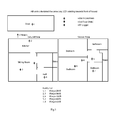
- RSSI Test 1 RSSI Test 3 RSSI Difference 4 (Hall) -75 dBm -75 dBm 0 2 (Kitchen) -71 dBm -67 dBm 4 5 (Bedroom 1) -87 dBm -87 dBm 0 3 (Utility room) -67 dBm -79 dBm -12 7 (Bedroom 3) -87 dBm -87 dBm 0 6 (Bedroom 2) -95 dBm -91 dBm 4 8 (Bedroom 4) -79 dBm -91 dBm -12
- RSSI Test 3 RSSI Difference 4 (Hall) -71 dBm -71 dBm 0 1 (Sitting room) -67 dBm -67 dBm 0 5 (Bedroom 1) -83 dBm -83 dBm 0 3 (Utility room) -51 dBm -59 dBm -8 7 (Bedroom 3) -75 dBm -75 dBm 0 6 (Bedroom 2) -79 dBm -79 dBm 0 8 (Bedroom 4) -71 dBm -71 dBm 0 1 (Sitting room) -67 dBm -67 dBm 0 5 (Bedroom 1) -83 dBm -83 dBm 0 3 (Utility room) -51 dBm -59 dBm -8 7 (Bedroom 3) -75 dBm -75 dBm
- RSSITest 3 RSSI Difference 1 (Sitting room) -71 dBm -75 dBm -4 2 (Kitchen) -75 dBm -71 dBm +4 5
- Bedroom 1 -71 dBm -71 dBm 0 3
- Utility room -63 dBm -63 dBm 0 7
- Bedroom 2 -79 dBm -79 dBm 0 8
- Bedroom 4 -63 dBm -63 dBm 0
- a monitoring device may incorporate alarm condition sensing and so be a combined alarm device and monitoring device.
Abstract
Description
- The invention relates to networks of RF alarm devices, such as fire, smoke, or intrusion alarm devices.
- Such alarm devices have been known for some time, examples being
US5587705 (Morris ),EP1501060 (E.I. Technology), andEP1903523 (E.I. Technology), the contents of which are incorporated herein by reference. - A problem with such devices is that when there are several in a network one or more might not communicate adequately, despite the controllers performing message repeating in a manner such as described in
EP1903523 . There are many reasons why a device may not be able to communicate, such as: - metal obstructions are put into the RF path and so attenuating the signal,
- movement of people or furniture in and out of the path,
- building renovations,
- destructive interference between the original signal and its reflection off a metal surface, and/or
- EMI from RF devices.
- The conventional mechanism for monitoring status is that each device sends an RF status message to the panel (or other monitoring device) directly at the required intervals. This works if all of the devices are well within the range of the panel, such that the panel receives the signals with a good "fade" margin. A fade margin is usually specified, which can be in the range of 3dB up to 30dB, to allow for the signal being attenuated due to factors such as those mentioned above.
- However, if the RF signals being received by the panel are not sufficiently strong, then at least one repeater will be needed. In fact, to ensure very high reliability, systems are now often configured as "mesh" networks, where some or all of the devices repeat the RF messages, such that all devices receive the RF messages through at least two or ideally more different paths.
- Due to battery life considerations and also to reduce RF transmissions to a minimum as required by some standards and for good practice, the status messages are normally very short, for example, in the range of 2 to 50 ms long. With battery-powered transceivers, operating on 1% duty cycle bands, they typically turn on the receivers for maybe 1 ms every 3 seconds to check for RF signals. This works for decoding messages that are over 3 seconds long, but not for short status messages. The conventional solution to this is to leave the RF receiver in the repeater on continuously. This means in practice that it must be mains powered as receivers typically draw over 10mA. The commonly-used Lithium cell CR123 only has a capacity of 1500mAh, which would only last less than a week.
- Furthermore, some protocols allow messages to be repeated 3 or more times to extend the range and to improve the reliability. This introduces added complexity.
- After installation of an RF system it is very important to assess its reliability. In fact many standards call for radio surveys to be done for this purpose. This is sometimes done by bringing an RF signal strength meter to approximately the position of each RF device and recording the transmission and reception of signals from a panel (or to other monitoring device). This is not very accurate as the antennas are not in the exact position of the antennas in the RF devices and also the actual device transmitter power and receiver sensitivity are not been measured. A further complication is that with repeaters/mesh networks there are many different RF paths to be assessed. For example with 12 devices in a network there are (12 X 12) - 12 = 132 RF paths to be assessed.
- The invention addresses these problems.
- According to the invention, there is provided a wireless alarm device network comprising:
- a plurality of alarm devices each comprising a processor, a wireless communication interface, and a condition sensor, the devices being adapted to communicate by wirelessly transmitting messages,
- wherein each device is adapted to, in a learning mode, automatically register in a monitoring cluster according to received signal strengths, in which it recognises a device as being in its cluster if at least received signal strength exceeds a threshold; and wherein each device is adapted to monitor each other device or devices in its cluster, and to generate an alert if it determines that a device in its cluster is not sending messages.
- In one embodiment, signal strength is determined according to broadcasts of messages during the learning mode in which each device learns identifier codes of directly-communicating cluster family member devices.
- In one embodiment, the devices are adapted to perform the following during the learning mode:
- a first device requests a second device that it receives messages most strongly from to monitor it,
- the second device accepts only if it receives messages from the first device with sufficient fade margin,
- if the second device accepts it registers the first device as a member of its cluster,
- if the first device fails to get monitoring agreement from the second device it requests a next device with the next strongest signal to monitor it, and repeats this step until it is monitored, and
- the other devices behave similarly until all are being monitored.
- In one embodiment, each device is adapted to generate an alert only if:
- it does not directly receive messages from a device in its cluster, and
- it does not learn that another device has received messages from said device in a specified time.
- In one embodiment, the monitoring cluster size is preferably two or three, with each device having only one or two cluster members.
- In one embodiment, the devices are synchronised with a time clock so that they communicate in pre-set time periods. Preferably, length of an intra-cluster status message is at or below 100ms.
- In one embodiment, a device is adapted to broadcast a trigger intra-cluster status message which triggers the other devices in its cluster to respond. In one embodiment, at least one device is adapted to transmit a status message in a specified sequence, to prevent clashing, upon receipt of a status message. Preferably, the specified sequence includes both when to transmit the status message and when to listen for the other messages. In one embodiment, said broadcasts are in a defined pattern.
- In one embodiment, at least one device is adapted to stop monitoring another device in its cluster if its messages are becoming intermittent, provided it is being monitored by another device.
- In one embodiment, the network includes a monitoring system and at least one device is adapted to download to the monitoring system, upon a monitoring system request, data concerning devices it is monitoring in its cluster. Preferably, said data includes latest RSSI level data. Preferably, the monitoring system is adapted to generate a two-dimensional table indicating devices that are in direct communication and the level of repeat between those not in direct communication. In one embodiment, the monitoring system is adapted to generate a display based on said table, the display indicating to an installer an assessment of the network reliability
- In one embodiment, at least some devices are adapted to piggyback on a first status message by transmitting their status messages after it in a specified sequence, to prevent clashing. Preferably, the specified sequence includes both when exactly to transmit the short status message along with when to listen for the other messages, to prevent a device needing to both listen and transmit at the same time.
- In one embodiment, at least some devices are adapted to send messages including their own serial numbers, and if a device fails to hear its own serial number, to send an alert message indicating that it is not being monitored by at least one other device. In one embodiment, each device is adapted to first send a request command asking which devices are monitoring a particular device, and to determine from responses if at least one other device is monitoring said device.
- In one embodiment, at least some devices are adapted to directly receive and process inter-cluster messages from devices which are outside of its cluster, and to avoid raising an alert if it does not receive a message from a cluster member device if it determines from said inter-cluster messages that another device has received a message from said cluster member device.
- In one embodiment, said devices are adapted to process only inter-cluster messages received during a pre-defined immediately-preceding time period.
- In one embodiment, said alarm devices include smoke, heat and toxic gas alarm devices.
- In another aspect, the invention provides a wireless alarm device comprising a processor, a wireless communication interface, and a condition sensor, the device being adapted to communicate by wirelessly transmitting messages, wherein the device is adapted to:
- in a learning mode, automatically register in a monitoring cluster according to received signal strengths, in which it recognises another device as being in its cluster if at least received signal strength exceeds a threshold; and
- monitor each other device or devices in its cluster, and to generate an alert if it determines that a device in its cluster is not sending messages.
- In one embodiment, signal strength is determined according to receiving and processing by the processor of broadcasts of messages during the learning mode in which the device learns identifier codes of directly-communicating cluster family member devices
- In one embodiment, the device is adapted to generate an alert only if:
- it does not directly receive messages from a device in its cluster, and
- it does not learn that another device has received messages from said device in a specified time.
- In one embodiment, the device is adapted to directly receive and process inter-cluster messages from devices which are outside of its cluster, and to avoid raising an alert if it does not receive a message from a cluster member device if it determines from said inter-cluster messages that another device has received a message from said cluster member device.
- The invention will be more clearly understood from the following description of some embodiments thereof, given by way of example only with reference to the accompanying drawings in which:-
-
Fig. 1 is a diagram illustrating clustering of devices in a smoke alarm network of the invention, -
Fig. 2 is a table of RF signal strength data generated by the network; -
Fig 3 is an example of three clusters in which one device A is not monitored; -
Fig. 4 is a sample plot for RSSI strength from a device as detected at a fixed position over a period of time; and -
Fig. 5 is a diagram of buddy communication margins for a sample test scenario. - Referring to
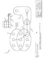
Fig. 1 a wireless RFsmoke alarm network 1 comprises alarm devices or "units" A to J and L located in a three-storey building with a two-storey annex. Each device has conventional architecture in hardware terms, with a micro-controller, output LEDs, output sounder, condition sensor (for example for smoke, toxic gas, heat, or intruder presence), and an RF transceiver. The invention lies mainly in the manner in which the micro-controller is programmed to process received messages, generate output messages, and control the light and sound output devices. Each device learns its neighbouring devices during a learning phase. It automatically, on an ad hoc basis, forms clusters which are overlapping. In this example the devices A - L have automatically formed fourclusters Fig. 2 . During the learning phase each device activates an LED to indicate that it has found at least one device ("buddy") with which it is in a cluster. - In one embodiment, each device in a cluster monitors at least one device in the cluster and is itself monitored in return. A device in a cluster only generates an alert (such as activating the LEDs in a particular manner, and/or sending a signal to the monitoring device K) if it identifies a problem. Faults are exceptional so they only occur rarely - this means that the repetition of fault messages normally has an insignificant effect on battery life.
- In one embodiment, if one device does not receive an RF status message at the required time (possibly after re-trying to contact the "missing" device a number of times) it sends out a 3.5 second long message, saying "device missing with serial number "XXXXX" and this is repeated by the appropriate devices. The message is therefore heard by all of the devices. The monitoring device K or a panel can then show that a device is missing and/or relay the message to external devices or servers via GSM or WiFi, for example.
- The invention solves a number of technical problems associated with RF mesh alarm networks:
- (a) Monitoring with low power, to allow long life battery powered repeaters to be used.
- (b) Assessing the reliability of mesh networks and helping to identify fixes if needed.
- The advantage (a) is achieved using the following features:
- The devices automatically forming themselves into clusters that monitor each other without the need for repeaters, and only fault messages being repeated.
- "Self-healing" monitoring clusters allows for a device to stop monitoring another in its cluster, if its RF messages are becoming intermittent, provided it is being monitored by another device.
- Accurate clock synchronisation allowing the sampling to be speeded up only when the messages are due, so short messages can be detected. This minimises the battery drain.
- An alternative to synchronised clocks is to allow other devices to "piggyback" on the first long status transmission as they quickly transmit their status messages after it (in a specified sequence, to prevent clashing). The specified sequence includes both when exactly to transmit the short status message along with when to listen for the other messages - as a device cannot both listen and transmit at the same time.
- Item (b) has the following advantageous features:
- The installer downloads from each device to a monitoring system such as a PC , data concerning the device(s) it is monitoring in its cluster along with the latest RSSI level that it was received at. This is updated each time it receives any messages from one of the devices in its cluster, for example status messages, button tests, or alarms. This allows a two-dimensional table to be drawn showing those that are in direct communication and the level of repeat between those not in direct communication. Therefore the monitoring system can automatically assess the reliability, quantify it, and suggest fixes if it is inadequate.
- This allows the maintenance technician (or user) to check the integrity and reliability of the RF links, allowing them to assess if the network has changed and if so to inform of the appropriate action to take.
- In one example there are 12 devices in the network and if there is a fault message an alert must be generated after at most 4 hours. The alert may be displayed on a monitoring panel (such as the monitoring device K), or no such device then the device will flash its blue LED once every 45 seconds; if two devices are missing they flash their blue LED rapidly twice every 45 seconds and so on. The horns could also be made beep at the same time if required.
- There is a two-step set-up coding procedure: the first to set up the clusters of two or more devices, and the second for house coding. When put into the cluster mode the devices just broadcast their own serial numbers continuously for at least 15 minutes. The installer then confirms that each device is flashing its blue LED at least 2 times, to indicate it is in range of at least one other device. The device now stores the serial numbers of the other device in its cluster as it must monitor at least one of these in the future.
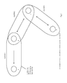
- There is a small possibility that all of the devices could show that they are in clusters of two or more, yet some are not being monitored. For example, consider four devices A, B, C and D as illustrated in
Fig. 3 . - A is monitoring B (cluster 1) - it is giving therefore two flashes
- B is monitoring C (cluster 2) - it is giving therefore two flashes.
- C is monitoring B (cluster 2) - it is giving therefore two flashes.
- C is monitoring D (cluster 3) - it is giving therefore two flashes.
- D is monitoring C (cluster 3) - it is giving therefore two flashes.
- From the LED flashes indicating the number of devices being monitored everything appears satisfactory. But A is not being monitored. The reciprocity theorem in physics would seem to rule this out i.e. that the RF path one way A to B, should be equal to the RF path the other way B to A. However the theorem assumes the transmitter power and receiver sensitivity are the same in both devicess and this is not necessarily the case due to circuitry tolerances. So, for added reliability after the initial cluster formation a command is given for each device, in turn, to list the devices it is monitoring. If a device fails to hear its own serial number, indicating that it is not being monitored by at least one other device it generates an alert.
- While in the monitoring cluster mode devices could also possibly store the RSSIs (Receive Signal Strength Indicator) levels at which they received the various serial numbers from the other devices, for downloading subsequently if needed, so that the RF signal strengths and multiple paths can be analysed to assess the potential system robustness and reliability.
- As an example of variability of RF emissions,
Fig. 4 shows the distribution of signal strengths received by a test receiver over a period in the order of hours, all from the same device at the same position. The horizontal axis is signal strength in dBm and the vertical axis is number of occurences. The received signal strengths range from 72dB to 92dB. - In some embodiments each monitoring cluster size is kept to two or three devices, and so each device may be regarded as having one or two "buddy" devices in its cluster. While, in this case the monitoring cluster size is only 2 or 3, each device will also receive some messages from other devices in direct communication. These messages include status updates for the device itself and it also includes the serial numbers of up to three other devices whose status message it has heard in the previous 20 minutes. These are the three strongest status messages this device will have heard. Therefore a particular device will not raise an alert if it does not receive a message from a buddy, if it knows from these messages that another device has received a message from it, thus confirming that it is operational and in communication. This deals with the situation where there is a temporary block in the RF path between buddy devices.
- The message table format in the micro-controller's memory between buddies may be as follows for some embodiments:
- Bit 7:
- Buddy Confirmed Rx
- Bit 6:
- Buddy Confirmed Tx
- Bit 5:
- Buddy Request Sent
- Bit 4:
- Buddy Found
- Bits 3-0:
- Average RSSI Level = 4dB steps
- Also, in another embodiment, the network may not include a dedicated monitoring device such as the device K in
Fig. 1 . This is because each device can raise its alert without need for such a device, for example by activating LEDs and/or a sound emitter as appropriate. - During house coding the devicess are then "told" (in some way e.g. by pressing the house code button or by an RF transmitter) to re-broadcast all of the serial numbers they have learned. Alternatively, they can automatically after a suitable time interval of
say 15 minutes, go on to re-broadcast all the serial numbers they have learned. They would flag the serial numbers to indicate repeat level - 0 is a device itself, 1 is received directly, 2 is received after one repeat, 3 is received after two repeats, and 4 is received after three repeats. - All the devicess store the house code numbers in the usual fashion, except that they add a flag to identify the devices(s) in their cluster that they must monitor. Assume say 3 are within range and so form a cluster of 4. Now, after four hours each in turn will transmit a 3.5 second status message. This will be received by the other 3 and they will note that they have received the three messages. If at some stage a device misses one of the three devices it is monitoring, it will send out a 3.5 second "device missing" message with the missing device's serial number. This will be repeated by all the other repeater devices and will therefore be heard at the panel (or other fault indicating device).
- If a device "hears" the message with its own serial number, saying it is missing, it can send out (or re-send out) its status message. The device which sent the original device-missing message, or any device that heard the "device-missing" message can now send a new message saying "device restored" serial number XXXXX" (if it receives the new status message). This allows the fault indicator to be quickly cancelled.
- The system can also re-configure which devices are monitoring which in a particular cluster so as to eliminate non-genuine fault signals being sent. This would be done in such a way as to prevent "orphans" being generated, that is a device being left such that it is not monitored by any other device. One way to do this is for a device Y which is getting intermittent signals from say device X and wants to stop monitoring it, first sending out a request command WDMX (Which Device Monitors X) asking "which devices are monitoring device X". All the relevant devices reply and the messages are repeated. Therefore as long as device Y hears that at least one other device is monitoring device X it can safely stop monitoring it. As with some simple compact programming codes only one serial number is included in the message, the devices would respond with the message code and their own serial number indicating that they are monitoring the device mentioned in the request command. For this to work, only one device can be requesting this information on a particular device at a time. The protocol would allow for this by forcing devices wanting to use this command to wait for sufficient time for the initial request command WDMX to be fully answered including all the repetitions.
- As each device would be sending out a 3.5 second message every 4 hours, this would constitute an average current battery draw of (assuming devices draw 30mA while transmitting RF) (3.5)(30 X 10 -3 )/{(4)(60)(60)} + (0.2)(15 X 10 -3 )/{(4)(60)(60)}

- The second term is to allow for the receiver being on for 0.2 seconds (to receive the messages from the other 3 devices) and that it draws 15mA during that time. Supplying 7.5 µA for a year requires 65.7mAh. With a 1500mAh battery, and ignoring other drains, this would last 22.8 years. Allowing for the additional currents such as to power the smoke alarm and also to turn on the RF receiver every 3 seconds, a 10 year battery life can be feasible. Extending the monitoring period from 4 hours to for example 24 hours or longer, would significantly reduce the drain on the battery.
- If each device has an accurate clock crystal, each with a tolerance of say 20 ppm, and the status messages are being transmitted precisely every 4 hours then the following could be done. The status message length could be reduced to 100ms (i.e. 10 packets of the 10ms message). To detect this, all the devices would need to increase their sampling i.e. turning on their receivers, from once every 3 seconds to once every 50ms (to give about 2 chances of detecting the RF status message) as it comes up to the time when the message is due.
- Assuming there is a 40ppm "error" or drift in the time, in order to receive and decode the RF packet, the receivers would need to increase their sampling rate to once every 50ms when a message was due for

- It would have to do this 3 times (as there are 4 devices in the cluster and it needs to hear the other 3). So, the average current would be

- The 25 in the denominator is because the duty cycle is roughly 2ms/50ms for the sampling.
- In addition, to decode each message takes about 20 X 10-3 second, so with 3 messages to be decoded, this gives:

- In addition, the device would also have to transmit one 100ms message every 4 hours and this would take:

- The total current is just 0.239 µA. To supply this for 1 year requires 2.09 mAh. This is a very big improvement over the 65.7mAh required when the message transmitted is 3.5 seconds long. The accurate timing crystal clock could possibly draw an additional 0.5 microamps in addition to the above.
- If the synchronised clock approach above is not used the following can be done to reduce the current drawn - just one device, every four hours broadcasts for 3.5 seconds and the others broadcast for just 50 ms each in sequence afterwards., as all the receivers turn on at the end of the 3.5 second transmission, while they are not transmitting.
- So, every 4 hours one alarm transmits for 3.5 seconds, it then turns on its receiver and the other 3 transmit their status messages directly afterwards in a defined pattern(while also keeping on their receivers when they are not transmitting, to hear the other devices). Every 4 hours each device takes turns in turning on for 3.5 seconds to spread the burden.
- If the monitoring panel K knows that a particular device was being monitored by at least 2 devices, it would not show a fault unless it heard it from two different devices. Unfortunately with a simple protocol having just a single serial number in the message there is no way for the panel to know it received the device message from two different devices, or if it was just the original message being repeated. To avoid this problem, if a device misses another device it broadcasts the 3.5 second message that it is missing. If another device has heard from the "missing" device, in say the previous 15 minutes, then it broadcasts a "device restored message". The panel then knows that at least one device is in contact so it does not show a fault. Also the panel can send the request command "WDMX" asking "which devices are monitoring device X", to establish the reliability of the monitoring of a particular device.
- In addition, the device that missed this device can now delete it from its cluster (say if this happens twice for confirmation that it was not just one-off RF blocking event), to stop the panel showing intermittent faults, but more importantly not to reduce the battery life on the devices which would be transmitting the repeated 3.5 second "device missing" message every 4 hours along with the repeated 3.5 second "device restored" message every 4 hours. This should not leave any device unmonitored, and hence the two commands:
- the one used after the clusters have been formed which gets the devices to state the devices they are monitoring, and
- the request command WDMX used before a device stops monitoring another device.
- Referring again to
Fig. 1 , twelve RF devices are installed in a three storey house with a two-storey annex. A panel or other RF monitoring device is included. The circles show the RF devices that are in direct range of each other. Initially, all of the devices are put into the cluster mode, where they just broadcast their own serial numbers. Incluster 1 units A, B and C will flash their blue LEDs six times (every 10 seconds) to show there are 6 devices in range (including the device itself). Units D, E and F will flash theirLEDs 9 times as they are members of bothcluster cluster 2, as well as D, E and F flashing theirLEDs 9 times, units G and H and will flash theirLEDs 6 times. Unit I will flash itsLED 7 times as it is in contact with 5 units incluster 4 and one in cluster 3 (which including itself gives 7). Incluster 3, I will flash itsLED 7 times and J will flash itsLED 4 times (for I, L, K and itself). Incluster 4, J will flash itsLED 4 times and L and K will flash theirLEDs 3 times. - The devices in each of the clusters will now monitor the rest of the devices in the cluster. If for any reason a device stops transmitting its status message (or if it cannot be heard) every 4 hours the other devices in the cluster will broadcast messages (with the missing device's serial number) indicating that the device is missing. In the illustration it is assumed that device A has become defective. Device B now sends out a "device missing with A's serial number" message. This is relayed to E, I, J and eventually to the monitoring device K.
- The invention provides a straightforward method for establishing the actual signal strength between all the devices and how many multiple paths there are through the repeaters. This information can then be used to predict the reliability of the system and so help decide whether measures such as adding a repeater, re-orientating antennas, or re-locating a device are needed.
- After the system is installed, cluster coded, and house coded, the installer goes around to each RF device in turn and asks it to download data concerning all the devices with which it is in direct communication along with the RSSI levels in (dBm) that it received the communication at, to an electronic data logger (usually hand held). Alternatively this information can be broadcast by each device in sequence and repeated so it is received by the panel or other monitoring device.
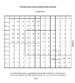
- The data received from all of the devices can then be compiled into a table as shown in
Fig. 2 , for a configuration such that inFig. 1 . This table shows if all the devices are in communication with each other and whether they are receiving the message directly (along with the RSSI level) or after being repeated once (digit 2), twice (digit 3) or three times (digit 4).Digit 1 would indicate direct communication. The data in this table can be used to construct diagrams such as those inFig. 1 to facilitate the installer viewing the multiple paths and signal strengths and potentially vulnerable links. This data clearly shows that the communication between the devices inclusters cluster 3 as this linkscluster 4 toclusters - Typically, devices will receive down to -100dBm and as
Fig. 2 shows, the signal strength between I to J and between J to I are both -80dBm, so this shows that there is a 20dB fade margin. The software can be used to set the relevant criteria such that it can tell the installer how reliable the system is. If a 20dB margin was deemed to be inadequate, then the software could be used to tell the installer to take the appropriate corrective action such as adding a further repeater in the vicinity of I and J. - The acceptable fade margin between devices could be varied depending on the number of multiple paths between the devices such that with three or more multiple paths the acceptable fade margin is low (possibly 3 dB), with 2 paths it is medium (possibly6 dB) and with just a single path it is high (possibly 10 dB).
- As outlined above in some embodiments the cluster size may be restricted to only 2 or 3. To set up the monitoring clusters, the devices may be put into a monitoring set-up mode. This can be done by a unique sequence of button presses, such as pressing the house code button and holding it until a tri-colour LED turns green; alternatively it could be done by pressing the house code button and at the same time pressing the device's test button. Or, it could be put into monitoring set-up mode by simply transmitting the required RF coded message from an RF installation/diagnostic tool.
- In one embodiment, for 5 minutes each device now transmits its own house code serial number in a 50 ms long message, (these messages are not repeated by any of the other devices) every 5 seconds. Each device now measures the RF signal strength (RSSI) of each device that is in range. Over the 5 minutes it will receive about 60 messages from each device in range and it will calculate the average RSSI from the 60 readings.
- Each device now has a table showing the signal strengths of all of the devices in direct range. A device processor now looks through its table and selects the device which sent it the strongest signal. Provided this signal is strong enough (e.g. has a specified fade margin of 15 dB or more above the minimum RF reception level) it now requests this device to be its "buddy". When the potential buddy receives the request, it consults its table and once it is also receiving this device with sufficient fade margin, it sends a message to be the first device that it agrees to be its buddy.
- Similarly, all the other devices seek to set up such clusters. If a device is not receiving any other device with sufficient margin, then it cannot buddy and will continue to flash its blue LED twice rapidly every 40 seconds. The installer now has to take remedial action such as adding another device closer to it, rotating the device, extending the antenna, or re-locating it. The RF installation/diagnostic tool gives the signal strength etc. which can help resolve this.
- If a device requests another device to be a buddy but the proposed buddy is not receiving the requester's RF signal with sufficient margin it will not reply stating it will be a buddy. After a short period the first device now looks at its RSSI strength table and picks the next device with the second strongest RSSI. It now requests this device to be a buddy as above. Each device continues in this manner until it has found at least one buddy. In this scheme one device can be a buddy of two or more other devices. With an odd number of devices, at least one device will have to monitor two buddies. In an extreme case, one device at the centre might have to be the buddy of all the devices on the periphery (if all the other devices were not within range of each other). So, when all the devices have found buddies, they stop flashing their blue LED twice every 40 seconds, so the installer now knows everything is satisfactory.
- Every 20 minutes (when on mains power) each device sends out its short (typically 50ms) status message. The buddy hears it and takes no action. If a device fails to receive such a message from a
particular buddy 6 times over 2 hours it flashes its blue LED twice every 40 seconds to indicate to the user that a buddy is not in communication. It can additionally or alternatively beep if required. It can also send a 3.5 second long message, which is repeated by all the other devices, stating "device xxxx is missing" and this can be picked up by a monitoring device. This monitoring device can give a visual warning that an identified device is missing and also send this information to a call centre, smart phone or any other appropriate device. - For battery-powered devices (or with mains powered devices when the mains is off) the status messages are only sent once every 12 hours (to conserve power). In this case the message lengths have to be increased from 50ms (0.05s) to 3.5 s. Battery powered devices in standby turn on their receivers once every 3 s, whereas on mains they turn on their receivers every 20ms (0.02s)). In this case if two of the status messages are missed from a buddy, the warnings as above are given after 24 hours.
- A device could lose communication with its buddy because the RF path between them was blocked by renovations, furniture being moved etc. However, the network could still be perfectly satisfactory as other devicess in the mesh can repeat the alarm and other messages, by-passing the obstructed path. With the scheme as outlined alone, the user would be informed that one device was out of communication whereas the network could be perfectly capable of operating as required.
- Warnings are only given if all of the paths in the mesh network are disrupted as follows. Each device sends out its status message (every 20 mins or 12 hours). However, along with its own serial number, it now also adds on up to three other status message serial numbers. These are from the devices it has received the strongest RSSI status signals previously (within the required interval). Now, a device monitoring a buddy, if it misses the direct buddy status message, will check to see if some other device has reported that it has heard its status message. This will therefore only report a buddy missing if it misses all the required status messages itself and also if no other device has reported hearing that device's status message..
- This scheme will mean that the time before a fault is given will be extended. Say a device is removed. The direct buddy will miss the direct status messages. However, other devices may still have the "memory" of the previous received status message, so until this is cleared, the original buddy "monitor" will not report a fault.
- A particular device keeps track of the status messages from all the different devices it is monitoring by setting a different timer for each to time out in 2 hours when on mains. Every time it receives a status message, either directly or through another device, it resets the timer to zero. If a timer times out for a device that is one of its buddies, it gives the "buddy missing" warning of two rapid flashes every 40 seconds and sends the 3.5 second message to any monitoring device.
- The installation or diagnostics tool in one embodiment consists of an RF transceiver with software for the RF protocol configured in a USB stick format. This would be plugged into a laptop, PDA, or other appropriate device.
- House code mode entry will clear all previously stored RSSI levels and buddy settings. Factory mode restore will clear all RSSI levels, buddy settings, learn mode repeat levels, and all stored serial numbers.
- The device will keep a log of the repeat level that the first valid house code message has been received at from each of the devices in the system A total of four different repeat levels are allowed. This log is stored in the EEPROM, one location for each device, adjacent to the serial number location. The original house code message will be sent at repeat level F0 (level 3 - the maximum level). This code is pre-programmed into the location adjacent to the device's own serial number. This level will be then decremented by the receiver before being stored in the EEPROM. This will thus be stored as E0, D0, or C0. The minimum received repeat level stored will be C0. House code messages received at this level will be stored in the EEPROM as '00'. When the house code table is being repeated, this level will be retrieved and included in the outgoing message as the repeat level, except if the stored level is '00' the house code message will not be transmitted. This will ensure that house code messages can be repeated a maximum of three times.
-
Entry: Press and hold House Code button until blue LED lights, then release. LED flashes rapidly and device is in House Hode mode. All Device Entry: Place device in House Code mode as described above, then release all buttons. Press and hold House Code button again until blue LED lights, then press the smoke alarm test button. When blue LED flashes rapidly, release both buttons. Device sends a House Code Entry command and is now in House Code mode. Exit: Press and hold house code button until blue LED lights, then release. LED does not flash rapidly, device is out of house code mode, and House Code exit message is sent. EEPROM Erase: Press and hold house code button until blue LED lights, continue holding until LED flashes rapidly. House Code exit message is sent, and EEPROM is now erased. - House coding must be completed before the monitoring setup mode is entered. This will be entered by sending a repeatable Monitor Mode Entry command, and will last 30 minutes. Monitor Mode Entry will clear all previously stored RSSI levels and buddy settings. In Monitor Setup mode, devices will send 50ms Monitor Setup messages every 5 seconds. These messages are not repeatable, thus are sent with a repeat level of C0. At the start of this mode, the green LED will be flashing 3 times every 5 seconds.
- When a Monitor Setup message is received from a known device, the RSSI level (after deducting a base level of -95dBm) will be added to a running total, and a counter will be incremented. These running totals are kept for each device (in RAM). When the device has been in Monitor Setup mode for 3 minutes, the running total is divided by the counter for each device to give an average receive level. If enough direct Monitor Setup messages have been received, the average is divided by 16 and added to E0 and the result stored in the EEPROM monitor level location. This table is used to decide which devices can become "buddies", i.e. which have a direct path with a received signal margin of at least 15dB. The device will only monitor at least one of these devices.
- After another 30 seconds (to allow all the other devices in the system to calculate their "buddy" tables), the device looks down its table of RSSI levels, and picks the device with the strongest signal. If this signal is strong enough to be a "buddy", a "buddy request" message is transmitted to that device. This message will contain both the sending and destination serial numbers. If the receiving device has also made a buddy of the sending device, it will reply with a "buddy confirmed" message, also with two serial numbers. Both these devices will now set a "Buddy" flag in their EEPROMs across from the corresponding serial number. Thus, buddies will be formed in pairs. At this point, the LED will stop flashing. If the device receives a "buddy request" message, even though it has already paired off with another device, it will still reply with a "buddy confirmed" message. This is to ensure that all other devices can find a buddy if one is available. All devices should have paired off after 5 minutes. If any device has not found a buddy by this time, the LED will remain flashing. This will indicate that it will need to be resited or a repeater fitted.
- There is also be a download function, where this table is transmitted. The method of transmission can be done by any one of a number of the conventional methods.
-
Entry: Ensure device is not in House Code mode. Press and hold House Code button until blue LED lights, then press the smoke alarm test button. When the blue LED flashes rapidly, release both buttons. Device sends a Monitor Mode Entry command and is now in Monitor Setup mode. Exit: Device will exit Monitor Setup mode after 30 minutes. - Each device in the network has a timer associated with it. These timers are pre-loaded with the timeout value (216 for a 24 hour timeout) at Monitor Setup Mode exit - as they share registers with the Monitor Setup mode RSSI averaging function. At regular intervals (every 18-20 minutes), the "buddy" timers are decremented by 1, and the non-buddy timers are restarted. Each device sends out a 3.0 second long "Monitor" message every 10 hours, with a repeat level of C0. This will prevent the message from being repeated. This will add approx. 2.5µA to the average current consumption. (Battery devices will not transmit the 20 minute "Device OK" status messages, thus saving 1.2uA, giving a net 1.3uA increase in current. They will still transmit the fault status messages). On receipt of any message, the timer corresponding to the serial number of the sending device will be restarted. Thus, it will take 2 messages to be missed (and also all of the 18 minute status messages) for the timer to count down to zero. Furthermore the timer is also reset if the buddy's serial number is received indirectly through another device's status message (as previously described).
- On devices where mains power is present, receipt of one of the 20 minute status messages will reset the timer to 150 instead of 216. This will reduce the monitoring time to 2 hours, thus speeding up the detection of any problem. If the mains power fails, all timers are reset to 216. This is because devices will no longer receive the short messages when the mains is gone, thus they have to wait for the long messages sent every 10 hours.
- Once any timer has reached 144, the device will enter a Monitor Fail mode. During this mode, the blue LED on the monitoring device will flash twice every 2 minutes. In this mode, it will send a 3.5s Check message with the serial numbers of both the missing device and the sending device every 4 hours for 2 days. The device receiving this message will immediately broadcast another Monitor message. Monitor Fail mode will be terminated immediately if the missing device returns. At the end of the 2 days, i.e. if the timer has reached zero, if the missing device is still missing, the blue LED flashing will cease at this time but the timer will still remain at zero, thus acting as a monitor fail flag. This timer will be restarted if the missing device returns at any later time.
- If a device is button tested after Monitor Fail mode has ended and any monitor timers are zero, after the alarm cancel transmissions are finished, the device will enter this Monitor Fail mode, this time for 4 hours. This will act as a memory feature for identifying any monitoring failures later.
- Monitoring faults are most likely to be due to degradation of one of the radio links between two buddy devices. If this is the case, the buddy network can be reformed by placing the system into Monitor Setup mode again. Entry into House Code mode or Monitor Setup mode erases all the buddy settings in the EEPROM. If a device is now no longer able to find a buddy, due to the degraded link, it will be flashing 3 times after Monitor Setup mode exit.
- If a monitoring system is present which can identify serial numbers and map them to specific locations (e.g. kitchen, living room, etc.), this device can broadcast a "Tell Missing" command. This command is fully repeatable, so it can be heard across the entire network. Flashing devices receiving this command will broadcast a "Missing" or "Tamper" command with the serial number(s) of the missing device, which is also fully repeatable. Thus, the monitoring system can identify which device is missing. This command would only be sent by an engineer troubleshooting the network.. Also, if the missing device receives this command, it will broadcast a fully repeatable "Monitor" message. This will restart all the clocks and end the LED flashing. The monitoring system will also indicate that the fault has been resolved.
- If an alarm is removed, other devices flash their blue LED (& beep once within 20 seconds), as the device being removed sends an RF message immediately.
- If RF communication is disrupted, the blue LED flashes on a nearby device to warn the user (within 2 hours if on mains power, and within 24 hours if on battery power). Disruption could be due to a device fault or RF barrier blocking/attenuating signal A comprehensive radio survey should be done before monitoring is enabled. Marginal devices may be excluded from the monitoring system.
- This is for reliability, troubleshooting and operation verification (e.g. for litigation). The time and date of the last and number of the following events are recorded in the device's own RF module (or device's own microcontroller).
- Alarm
- Button Tests
- Device Removed
- Device Fault
- Low Battery Device
- Low Battery Module
- Date Installed
- End of Life (Device)
- Mains Off
- Monitoring Fault (Buddy Missing)
- Interference present for over 30 seconds
- Device battery condition
- Module battery condition
- Optical Chamber contamination level
-
Event Last Occurrence Number of Occurrences Quality Level Time* Date Alarm 11.00 8/7/12 3 Button Test 13.00 1/9/12 35 Low Batt Device 0 Low Batt RF 0 Time in Service 7 years 3.5 months - End of Life 1/3/12 - Mains Absent 23.00 1/6/12 3 Monitoring Fit. Device Removed 4.00 7/8/12 1 Interference(30S) 18:00 30/8/12 3 7 Batt Device Volt 8 Module Volt Contamination 8 - Date Installed: 3/2/2012
- Location of alarm, based on GPS in Diagnostic Tool.
- The Time column above is given within 4 hours with a 10% clock tolerance. The clock stops when all power is off for battery voltage. In the Quality Level column, 10 is an un-depleted battery and 4 is the low battery level. For chamber contamination, 10 is a clean chamber and 4 indicates need for replacing or cleaning.
- This is implemented using a USB device plugged into a PC or plugged into a WiFi, router communicating with the Internet. It sends RF commands to configure devices such as:
- ● Go into House Code Mode
- ● Come out of House Code Mode
- ● Put devices into monitoring mode
- ● Remove a device from monitoring system
- ● Silence a device that is alarming from contamination (for extended period)
- ● Change monitoring period (e.g. on battery devices from 24 hours to 2 hours - reduces battery life)
- ● Stop a device being a repeater (only 10-12 repeaters per system)
- ● Enable analogue data transmission mode
- ● Change or disable other modes(e.g. cancel low battery beeps)
- ● Remove a particular house code from each device
- Download & display Event Log
- Download & display RF Signal Strength data and level of system RF attenuation margins These may be performed remotely.
- Periodically devices transmit analogue data and every 50 seconds when they are halfway to alarming in order to:
- Give very early pre-warning of alarm
- Give "Double Knock" ability so call centres or neighbours are not alerted until there is corroboration of a serious event.
- Give proof and information on events (if data recorded by external device)
- The following are example outputs from the diagnostics tool.
-
Known Serial Numbers Test 1 RSSI Test 3 RSSI Difference 4 (Hall) -75 dBm -75 dBm 0 2 (Kitchen) -71 dBm -67 dBm 4 5 (Bedroom 1) -87 dBm -87 dBm 0 3 (Utility room) -67 dBm -79 dBm -12 7 (Bedroom 3) -87 dBm -87 dBm 0 6 (Bedroom 2) -95 dBm -91 dBm 4 8 (Bedroom 4) -79 dBm -91 dBm -12 -
Known Serial Numbers Test 1 RSSI Test 3 RSSI Difference 4 (Hall) -71 dBm -71 dBm 0 1 (Sitting room) -67 dBm -67 dBm 0 5 (Bedroom 1) -83 dBm -83 dBm 0 3 (Utility room) -51 dBm -59 dBm -8 7 (Bedroom 3) -75 dBm -75 dBm 0 6 (Bedroom 2) -79 dBm -79 dBm 0 8 (Bedroom 4) -71 dBm -71 dBm 0 -
Known Serial Numbers Test 1 RSSITest 3 RSSI Difference1 (Sitting room) -71 dBm -75 dBm -4 2 (Kitchen) -75 dBm -71 dBm +4 5 (Bedroom 1) -71 dBm -71 dBm 0 3 (Utility room) -63 dBm -63 dBm 0 7 (Bedroom 3) -75 dBm -75 dBm 0 6 (Bedroom 2) -79 dBm -79 dBm 0 8 (Bedroom 4) -63 dBm -63 dBm 0 - It will be noted from the tables above that there will be changes expected due to orientation, either receiving or transmitting to the device that was rotated. A change of 4 dBm is the resolution of the RSSI available through the download command. A change +/- 4 dBm can indicate slight variations in the signal path. There are also unexpected changes in the signal path
- The invention is not limited to the embodiments described but may be varied in construction and detail. For example, a monitoring device may incorporate alarm condition sensing and so be a combined alarm device and monitoring device.
Claims (16)
- A wireless alarm device network (1) comprising:a plurality of alarm devices (A-L) each comprising a processor, a wireless communication interface, and a condition sensor, the devices being adapted to communicate by wirelessly transmitting messages,wherein each device is adapted to, in a learning mode, automatically register in a monitoring cluster (2-5) according to received signal strengths (RSSI), in which it recognises a device as being in its cluster if at least received signal strength exceeds a threshold; andwherein each device is adapted to monitor each other device or devices in its cluster, and to generate an alert if it determines that a device in its cluster is not sending messages.
- A wireless alarm device network as claimed in claims 1 or 2, wherein signal strength is determined according to broadcasts of messages during the learning mode in which each device learns identifier codes of directly-communicating cluster family member devices.
- A wireless alarm device network as claimed in claims 1 or 2, wherein the devices are adapted to perform the following during the learning mode:a first device (A-L) requests a second device that it receives messages most strongly from to monitor it,the second device (A-L) accepts only if it receives messages from the first device with sufficient fade margin,if the second device accepts it registers the first device as a member of its cluster,if the first device fails to get monitoring agreement from the second device it requests a next device with the next strongest signal to monitor it, and repeats this step until it is monitored, andthe other devices behave similarly until all are being monitored.
- A wireless alarm device network as claimed in claims 1 or 2 or 3, wherein each device is adapted to generate an alert only if:it does not directly receive messages from a device in its cluster, andit does not learn that another device has received messages from said device in a specified time.
- A wireless alarm device network as claimed in any preceding claim, wherein a device is adapted to broadcast a trigger intra-cluster status message which triggers the other devices in its cluster to respond; and wherein at least one device is adapted to transmit a status message in a specified sequence, to prevent clashing, upon receipt of a status message; and wherein the specified sequence includes both when to transmit the status message and when to listen for the other messages.
- A wireless alarm device network as claimed in any preceding claim, wherein at least one device is adapted to stop monitoring another device in its cluster if its messages are becoming intermittent, provided it is being monitored by another device.
- A wireless alarm device network as claimed in any preceding claim, wherein the network includes a monitoring system and at least one device is adapted to download to the monitoring system, upon a monitoring system request, data concerning devices it is monitoring in its cluster; wherein said data includes latest RSSI level data.
- A wireless alarm device network as claimed in claim 7, wherein the monitoring system is adapted to generate a two-dimensional table indicating devices that are in direct communication and the level of repeat between those not in direct communication; and wherein the monitoring system is adapted to generate a display based on said table, the display indicating to an installer an assessment of the network reliability.
- A wireless alarm device network as claimed in any preceding claim, wherein at least some devices are adapted to piggyback on a first status message by transmitting their status messages after it in a specified sequence, to prevent clashing; and wherein the specified sequence includes both when exactly to transmit the short status message along with when to listen for the other messages, to prevent a device needing to both listen and transmit at the same time.
- A wireless alarm device network as claimed in any preceding claim, wherein at least some devices are adapted to send messages including their own serial numbers, and if a device fails to hear its own serial number, to send an alert message indicating that it is not being monitored by at least one other device.
- A wireless alarm device network as claimed in claim 10, wherein each device is adapted to first send a request command asking which devices are monitoring a particular device, and to determine from responses if at least one other device is monitoring said device.
- A wireless alarm device network as claimed in any preceding claim, wherein at least some devices are adapted to directly receive and process inter-cluster messages from devices which are outside of its cluster, and to avoid raising an alert if it does not receive a message from a cluster member device if it determines from said inter-cluster messages that another device has received a message from said cluster member device; and wherein said devices are adapted to process only inter-cluster messages received during a pre-defined immediately-preceding time period.
- A wireless alarm device network as claimed in any preceding claim, wherein said alarm devices include smoke, heat, and toxic gas alarm devices.
- A wireless alarm device comprising a processor, a wireless communication interface, and a condition sensor, the device being adapted to communicate by wirelessly transmitting messages, wherein the device is adapted to:in a learning mode, automatically register in a monitoring cluster according to received signal strengths, in which it recognises another device as being in its cluster if at least received signal strength exceeds a threshold; andmonitor each other device or devices in its cluster, and to generate an alert if it determines that a device in its cluster is not sending messages.
- A wireless alarm device as claimed in claim 14, wherein signal strength is determined according to receiving and processing by the processor of broadcasts of messages during the learning mode in which the device learns identifier codes of directly-communicating cluster family member devices; and wherein the device is adapted to generate an alert only if:it does not directly receive messages from a device in its cluster, andit does not learn that another device has received messages from said device in a specified time.
- A wireless alarm device as claimed in either of claims 14 or 15, wherein the device is adapted to directly receive and process inter-cluster messages from devices which are outside of its cluster, and to avoid raising an alert if it does not receive a message from a cluster member device if it determines from said inter-cluster messages that another device has received a message from said cluster member device.
Applications Claiming Priority (1)
| Application Number | Priority Date | Filing Date | Title |
|---|---|---|---|
| IE20110457 | 2011-10-12 |
Publications (4)
| Publication Number | Publication Date |
|---|---|
| EP2581891A2 true EP2581891A2 (en) | 2013-04-17 |
| EP2581891A3 EP2581891A3 (en) | 2014-05-07 |
| EP2581891B1 EP2581891B1 (en) | 2015-10-28 |
| EP2581891B8 EP2581891B8 (en) | 2015-12-30 |
Family
ID=47010391
Family Applications (1)
| Application Number | Title | Priority Date | Filing Date |
|---|---|---|---|
| EP12188123.9A Active EP2581891B8 (en) | 2011-10-12 | 2012-10-11 | A low current RF alarm device mesh network |
Country Status (2)
| Country | Link |
|---|---|
| EP (1) | EP2581891B8 (en) |
| IE (1) | IE20120451A1 (en) |
Cited By (6)
| Publication number | Priority date | Publication date | Assignee | Title |
|---|---|---|---|---|
| EP2843636A1 (en) | 2013-08-23 | 2015-03-04 | E.I. Technology Limited | Monitoring and control of alarm systems |
| FR3013143A1 (en) * | 2013-11-14 | 2015-05-15 | Finsecur | DEVICE AND METHOD FOR SECURING A SITE |
| WO2015071606A1 (en) * | 2013-11-14 | 2015-05-21 | Finsecur | Method and device for deploying a link between at least one security system and an alarm centre |
| WO2017072559A1 (en) | 2015-10-30 | 2017-05-04 | Ebs Sp. Z O.O. | Alarm system and alarm transmitter |
| EP3093827B1 (en) | 2015-05-12 | 2018-06-20 | Honeywell International Inc. | Automatic reporting of prognosis data from wireless mesh sensors to cloud |
| WO2018115854A3 (en) * | 2016-12-21 | 2018-08-23 | Texecom Limited | Frequency hopping spread spectrum communication in mesh networks |
Citations (3)
| Publication number | Priority date | Publication date | Assignee | Title |
|---|---|---|---|---|
| US5587705A (en) | 1994-08-29 | 1996-12-24 | Morris; Gary J. | Multiple alert smoke detector |
| EP1501060A1 (en) | 2003-07-25 | 2005-01-26 | E.I. Technology Limited | A smoke alarm device |
| EP1903523A1 (en) | 2006-09-21 | 2008-03-26 | E.I. Technology Limited | Alarm systems |
Family Cites Families (2)
| Publication number | Priority date | Publication date | Assignee | Title |
|---|---|---|---|---|
| DE102008063454B4 (en) * | 2008-12-17 | 2012-05-31 | Siemens Aktiengesellschaft | Method for monitoring network nodes |
| GB201003826D0 (en) * | 2010-03-08 | 2010-04-21 | Texecom Ltd | An improved alarm system |
-
2012
- 2012-10-11 IE IE20120451A patent/IE20120451A1/en not_active Application Discontinuation
- 2012-10-11 EP EP12188123.9A patent/EP2581891B8/en active Active
Patent Citations (3)
| Publication number | Priority date | Publication date | Assignee | Title |
|---|---|---|---|---|
| US5587705A (en) | 1994-08-29 | 1996-12-24 | Morris; Gary J. | Multiple alert smoke detector |
| EP1501060A1 (en) | 2003-07-25 | 2005-01-26 | E.I. Technology Limited | A smoke alarm device |
| EP1903523A1 (en) | 2006-09-21 | 2008-03-26 | E.I. Technology Limited | Alarm systems |
Cited By (8)
| Publication number | Priority date | Publication date | Assignee | Title |
|---|---|---|---|---|
| EP2843636A1 (en) | 2013-08-23 | 2015-03-04 | E.I. Technology Limited | Monitoring and control of alarm systems |
| EP2843636B1 (en) | 2013-08-23 | 2018-06-13 | E.I. Technology | Monitoring and control of alarm systems |
| FR3013143A1 (en) * | 2013-11-14 | 2015-05-15 | Finsecur | DEVICE AND METHOD FOR SECURING A SITE |
| WO2015071606A1 (en) * | 2013-11-14 | 2015-05-21 | Finsecur | Method and device for deploying a link between at least one security system and an alarm centre |
| EP3093827B1 (en) | 2015-05-12 | 2018-06-20 | Honeywell International Inc. | Automatic reporting of prognosis data from wireless mesh sensors to cloud |
| WO2017072559A1 (en) | 2015-10-30 | 2017-05-04 | Ebs Sp. Z O.O. | Alarm system and alarm transmitter |
| WO2018115854A3 (en) * | 2016-12-21 | 2018-08-23 | Texecom Limited | Frequency hopping spread spectrum communication in mesh networks |
| US10848200B2 (en) | 2016-12-21 | 2020-11-24 | Texecom Limited | Frequency hopping spread spectrum communication in mesh networks |
Also Published As
| Publication number | Publication date |
|---|---|
| EP2581891A3 (en) | 2014-05-07 |
| EP2581891B1 (en) | 2015-10-28 |
| EP2581891B8 (en) | 2015-12-30 |
| IE20120451A1 (en) | 2013-05-08 |
Similar Documents
| Publication | Publication Date | Title |
|---|---|---|
| EP2581891B1 (en) | A low current RF alarm device mesh network | |
| US10966154B2 (en) | Master slave wireless fire alarm and mass notification system | |
| US10863732B2 (en) | Wireless notification systems and methods for electronic rodent traps | |
| KR100328853B1 (en) | System and method for supervising repeater by using wireless mobile | |
| US20120290857A1 (en) | Adaptive network and method | |
| WO2011055705A1 (en) | Relay method for alarm system and alarm | |
| JPH07170583A (en) | System for acquisiting and communicating remote data | |
| EP2843636A1 (en) | Monitoring and control of alarm systems | |
| JP2009003828A (en) | Radio alarm unit and radio communication device | |
| JP2015087885A (en) | Alarm system and notification method thereof | |
| US20190073895A1 (en) | Alarm system | |
| JP2013176034A (en) | Radio communication system | |
| EP3836107B1 (en) | Security monitoring system | |
| CN106060857A (en) | Wireless communication system, wireless communication apparatus, and wireless communication method | |
| JP2015014986A (en) | Alarm unit and alarm system | |
| JP2014204422A (en) | Radio communication system | |
| JP2013176033A (en) | Radio communication system | |
| WO2020039042A1 (en) | A security monitoring system, a node and a central unit therefor | |
| JP5707558B2 (en) | Wireless communication system, wireless signal data structure, receiver, and transmitter | |
| WO2021105111A1 (en) | A security monitoring system | |
| JP2011199544A (en) | Radio sensor network system |
Legal Events
| Date | Code | Title | Description |
|---|---|---|---|
| PUAI | Public reference made under article 153(3) epc to a published international application that has entered the european phase |
Free format text: ORIGINAL CODE: 0009012 |
|
| AK | Designated contracting states |
Kind code of ref document: A2 Designated state(s): AL AT BE BG CH CY CZ DE DK EE ES FI FR GB GR HR HU IE IS IT LI LT LU LV MC MK MT NL NO PL PT RO RS SE SI SK SM TR |
|
| AX | Request for extension of the european patent |
Extension state: BA ME |
|
| PUAL | Search report despatched |
Free format text: ORIGINAL CODE: 0009013 |
|
| AK | Designated contracting states |
Kind code of ref document: A3 Designated state(s): AL AT BE BG CH CY CZ DE DK EE ES FI FR GB GR HR HU IE IS IT LI LT LU LV MC MK MT NL NO PL PT RO RS SE SI SK SM TR |
|
| AX | Request for extension of the european patent |
Extension state: BA ME |
|
| RIC1 | Information provided on ipc code assigned before grant |
Ipc: G08B 29/06 20060101ALI20140403BHEP Ipc: G08B 25/00 20060101AFI20140403BHEP |
|
| 17P | Request for examination filed |
Effective date: 20141008 |
|
| GRAP | Despatch of communication of intention to grant a patent |
Free format text: ORIGINAL CODE: EPIDOSNIGR1 |
|
| INTG | Intention to grant announced |
Effective date: 20150612 |
|
| GRAS | Grant fee paid |
Free format text: ORIGINAL CODE: EPIDOSNIGR3 |
|
| GRAA | (expected) grant |
Free format text: ORIGINAL CODE: 0009210 |
|
| AK | Designated contracting states |
Kind code of ref document: B1 Designated state(s): AL AT BE BG CH CY CZ DE DK EE ES FI FR GB GR HR HU IE IS IT LI LT LU LV MC MK MT NL NO PL PT RO RS SE SI SK SM TR |
|
| REG | Reference to a national code |
Ref country code: GB Ref legal event code: FG4D |
|
| REG | Reference to a national code |
Ref country code: CH Ref legal event code: EP |
|
| REG | Reference to a national code |
Ref country code: AT Ref legal event code: REF Ref document number: 758313 Country of ref document: AT Kind code of ref document: T Effective date: 20151115 |
|
| REG | Reference to a national code |
Ref country code: IE Ref legal event code: FG4D |
|
| RAP2 | Party data changed (patent owner data changed or rights of a patent transferred) |
Owner name: E.I. TECHNOLOGY |
|
| REG | Reference to a national code |
Ref country code: DE Ref legal event code: R096 Ref document number: 602012011931 Country of ref document: DE |
|
| REG | Reference to a national code |
Ref country code: NL Ref legal event code: FP |
|
| REG | Reference to a national code |
Ref country code: LT Ref legal event code: MG4D |
|
| REG | Reference to a national code |
Ref country code: DE Ref legal event code: R081 Ref document number: 602012011931 Country of ref document: DE Owner name: E.I. TECHNOLOGY UNLIMITED COMPANY, IE Free format text: FORMER OWNER: E.I. TECHNOLOGY LTD., SHANNON, COUNTY CLARE, IE Ref country code: AT Ref legal event code: MK05 Ref document number: 758313 Country of ref document: AT Kind code of ref document: T Effective date: 20151028 Ref country code: DE Ref legal event code: R082 Ref document number: 602012011931 Country of ref document: DE Representative=s name: MITSCHERLICH, PATENT- UND RECHTSANWAELTE PARTM, DE |
|
| REG | Reference to a national code |
Ref country code: NL Ref legal event code: HC Owner name: E.I. TECHNOLOGY; IE Free format text: DETAILS ASSIGNMENT: VERANDERING VAN EIGENAAR(S), VERANDERING VAN NAAM VAN DE EIGENAAR(S); FORMER OWNER NAME: E.I. TECHNOLOGY LIMITED Effective date: 20151215 |
|
| PG25 | Lapsed in a contracting state [announced via postgrant information from national office to epo] |
Ref country code: LT Free format text: LAPSE BECAUSE OF FAILURE TO SUBMIT A TRANSLATION OF THE DESCRIPTION OR TO PAY THE FEE WITHIN THE PRESCRIBED TIME-LIMIT Effective date: 20151028 Ref country code: IT Free format text: LAPSE BECAUSE OF FAILURE TO SUBMIT A TRANSLATION OF THE DESCRIPTION OR TO PAY THE FEE WITHIN THE PRESCRIBED TIME-LIMIT Effective date: 20151028 Ref country code: IS Free format text: LAPSE BECAUSE OF FAILURE TO SUBMIT A TRANSLATION OF THE DESCRIPTION OR TO PAY THE FEE WITHIN THE PRESCRIBED TIME-LIMIT Effective date: 20160228 Ref country code: NO Free format text: LAPSE BECAUSE OF FAILURE TO SUBMIT A TRANSLATION OF THE DESCRIPTION OR TO PAY THE FEE WITHIN THE PRESCRIBED TIME-LIMIT Effective date: 20160128 Ref country code: ES Free format text: LAPSE BECAUSE OF FAILURE TO SUBMIT A TRANSLATION OF THE DESCRIPTION OR TO PAY THE FEE WITHIN THE PRESCRIBED TIME-LIMIT Effective date: 20151028 Ref country code: HR Free format text: LAPSE BECAUSE OF FAILURE TO SUBMIT A TRANSLATION OF THE DESCRIPTION OR TO PAY THE FEE WITHIN THE PRESCRIBED TIME-LIMIT Effective date: 20151028 |
|
| PG25 | Lapsed in a contracting state [announced via postgrant information from national office to epo] |
Ref country code: AT Free format text: LAPSE BECAUSE OF FAILURE TO SUBMIT A TRANSLATION OF THE DESCRIPTION OR TO PAY THE FEE WITHIN THE PRESCRIBED TIME-LIMIT Effective date: 20151028 Ref country code: PT Free format text: LAPSE BECAUSE OF FAILURE TO SUBMIT A TRANSLATION OF THE DESCRIPTION OR TO PAY THE FEE WITHIN THE PRESCRIBED TIME-LIMIT Effective date: 20160229 Ref country code: FI Free format text: LAPSE BECAUSE OF FAILURE TO SUBMIT A TRANSLATION OF THE DESCRIPTION OR TO PAY THE FEE WITHIN THE PRESCRIBED TIME-LIMIT Effective date: 20151028 Ref country code: LV Free format text: LAPSE BECAUSE OF FAILURE TO SUBMIT A TRANSLATION OF THE DESCRIPTION OR TO PAY THE FEE WITHIN THE PRESCRIBED TIME-LIMIT Effective date: 20151028 Ref country code: PL Free format text: LAPSE BECAUSE OF FAILURE TO SUBMIT A TRANSLATION OF THE DESCRIPTION OR TO PAY THE FEE WITHIN THE PRESCRIBED TIME-LIMIT Effective date: 20151028 Ref country code: RS Free format text: LAPSE BECAUSE OF FAILURE TO SUBMIT A TRANSLATION OF THE DESCRIPTION OR TO PAY THE FEE WITHIN THE PRESCRIBED TIME-LIMIT Effective date: 20151028 Ref country code: SE Free format text: LAPSE BECAUSE OF FAILURE TO SUBMIT A TRANSLATION OF THE DESCRIPTION OR TO PAY THE FEE WITHIN THE PRESCRIBED TIME-LIMIT Effective date: 20151028 Ref country code: GR Free format text: LAPSE BECAUSE OF FAILURE TO SUBMIT A TRANSLATION OF THE DESCRIPTION OR TO PAY THE FEE WITHIN THE PRESCRIBED TIME-LIMIT Effective date: 20160129 |
|
| PG25 | Lapsed in a contracting state [announced via postgrant information from national office to epo] |
Ref country code: CZ Free format text: LAPSE BECAUSE OF FAILURE TO SUBMIT A TRANSLATION OF THE DESCRIPTION OR TO PAY THE FEE WITHIN THE PRESCRIBED TIME-LIMIT Effective date: 20151028 |
|
| REG | Reference to a national code |
Ref country code: DE Ref legal event code: R097 Ref document number: 602012011931 Country of ref document: DE |
|
| REG | Reference to a national code |
Ref country code: FR Ref legal event code: PLFP Year of fee payment: 5 |
|
| PG25 | Lapsed in a contracting state [announced via postgrant information from national office to epo] |
Ref country code: DK Free format text: LAPSE BECAUSE OF FAILURE TO SUBMIT A TRANSLATION OF THE DESCRIPTION OR TO PAY THE FEE WITHIN THE PRESCRIBED TIME-LIMIT Effective date: 20151028 Ref country code: RO Free format text: LAPSE BECAUSE OF FAILURE TO SUBMIT A TRANSLATION OF THE DESCRIPTION OR TO PAY THE FEE WITHIN THE PRESCRIBED TIME-LIMIT Effective date: 20151028 Ref country code: SM Free format text: LAPSE BECAUSE OF FAILURE TO SUBMIT A TRANSLATION OF THE DESCRIPTION OR TO PAY THE FEE WITHIN THE PRESCRIBED TIME-LIMIT Effective date: 20151028 Ref country code: EE Free format text: LAPSE BECAUSE OF FAILURE TO SUBMIT A TRANSLATION OF THE DESCRIPTION OR TO PAY THE FEE WITHIN THE PRESCRIBED TIME-LIMIT Effective date: 20151028 Ref country code: SK Free format text: LAPSE BECAUSE OF FAILURE TO SUBMIT A TRANSLATION OF THE DESCRIPTION OR TO PAY THE FEE WITHIN THE PRESCRIBED TIME-LIMIT Effective date: 20151028 |
|
| PLBE | No opposition filed within time limit |
Free format text: ORIGINAL CODE: 0009261 |
|
| STAA | Information on the status of an ep patent application or granted ep patent |
Free format text: STATUS: NO OPPOSITION FILED WITHIN TIME LIMIT |
|
| 26N | No opposition filed |
Effective date: 20160729 |
|
| PG25 | Lapsed in a contracting state [announced via postgrant information from national office to epo] |
Ref country code: SI Free format text: LAPSE BECAUSE OF FAILURE TO SUBMIT A TRANSLATION OF THE DESCRIPTION OR TO PAY THE FEE WITHIN THE PRESCRIBED TIME-LIMIT Effective date: 20151028 |
|
| PG25 | Lapsed in a contracting state [announced via postgrant information from national office to epo] |
Ref country code: BE Free format text: LAPSE BECAUSE OF FAILURE TO SUBMIT A TRANSLATION OF THE DESCRIPTION OR TO PAY THE FEE WITHIN THE PRESCRIBED TIME-LIMIT Effective date: 20151028 |
|
| REG | Reference to a national code |
Ref country code: CH Ref legal event code: PL |
|
| PG25 | Lapsed in a contracting state [announced via postgrant information from national office to epo] |
Ref country code: MC Free format text: LAPSE BECAUSE OF FAILURE TO SUBMIT A TRANSLATION OF THE DESCRIPTION OR TO PAY THE FEE WITHIN THE PRESCRIBED TIME-LIMIT Effective date: 20151028 |
|
| PG25 | Lapsed in a contracting state [announced via postgrant information from national office to epo] |
Ref country code: CH Free format text: LAPSE BECAUSE OF NON-PAYMENT OF DUE FEES Effective date: 20161031 Ref country code: LI Free format text: LAPSE BECAUSE OF NON-PAYMENT OF DUE FEES Effective date: 20161031 |
|
| PG25 | Lapsed in a contracting state [announced via postgrant information from national office to epo] |
Ref country code: LU Free format text: LAPSE BECAUSE OF NON-PAYMENT OF DUE FEES Effective date: 20161011 |
|
| REG | Reference to a national code |
Ref country code: FR Ref legal event code: PLFP Year of fee payment: 6 |
|
| PG25 | Lapsed in a contracting state [announced via postgrant information from national office to epo] |
Ref country code: HU Free format text: LAPSE BECAUSE OF FAILURE TO SUBMIT A TRANSLATION OF THE DESCRIPTION OR TO PAY THE FEE WITHIN THE PRESCRIBED TIME-LIMIT; INVALID AB INITIO Effective date: 20121011 Ref country code: CY Free format text: LAPSE BECAUSE OF FAILURE TO SUBMIT A TRANSLATION OF THE DESCRIPTION OR TO PAY THE FEE WITHIN THE PRESCRIBED TIME-LIMIT Effective date: 20151028 |
|
| PG25 | Lapsed in a contracting state [announced via postgrant information from national office to epo] |
Ref country code: MT Free format text: LAPSE BECAUSE OF NON-PAYMENT OF DUE FEES Effective date: 20161031 Ref country code: MK Free format text: LAPSE BECAUSE OF FAILURE TO SUBMIT A TRANSLATION OF THE DESCRIPTION OR TO PAY THE FEE WITHIN THE PRESCRIBED TIME-LIMIT Effective date: 20151028 Ref country code: TR Free format text: LAPSE BECAUSE OF FAILURE TO SUBMIT A TRANSLATION OF THE DESCRIPTION OR TO PAY THE FEE WITHIN THE PRESCRIBED TIME-LIMIT Effective date: 20151028 |
|
| PG25 | Lapsed in a contracting state [announced via postgrant information from national office to epo] |
Ref country code: BG Free format text: LAPSE BECAUSE OF FAILURE TO SUBMIT A TRANSLATION OF THE DESCRIPTION OR TO PAY THE FEE WITHIN THE PRESCRIBED TIME-LIMIT Effective date: 20151028 |
|
| REG | Reference to a national code |
Ref country code: FR Ref legal event code: PLFP Year of fee payment: 7 |
|
| PG25 | Lapsed in a contracting state [announced via postgrant information from national office to epo] |
Ref country code: AL Free format text: LAPSE BECAUSE OF FAILURE TO SUBMIT A TRANSLATION OF THE DESCRIPTION OR TO PAY THE FEE WITHIN THE PRESCRIBED TIME-LIMIT Effective date: 20151028 |
|
| REG | Reference to a national code |
Ref country code: DE Ref legal event code: R082 Ref document number: 602012011931 Country of ref document: DE Representative=s name: MITSCHERLICH, PATENT- UND RECHTSANWAELTE PARTM, DE Ref country code: DE Ref legal event code: R081 Ref document number: 602012011931 Country of ref document: DE Owner name: E.I. TECHNOLOGY UNLIMITED COMPANY, IE Free format text: FORMER OWNER: E.I. TECHNOLOGY, SHANNON, IE |
|
| REG | Reference to a national code |
Ref country code: NL Ref legal event code: HC Owner name: E.I. TECHNOLOGY UNLIMITED COMPANY; IE Free format text: DETAILS ASSIGNMENT: CHANGE OF OWNER(S), CHANGE OF OWNER(S) NAME; FORMER OWNER NAME: E.I. TECHNOLOGY LIMITED Effective date: 20190226 |
|
| P01 | Opt-out of the competence of the unified patent court (upc) registered |
Effective date: 20230420 |
|
| PGFP | Annual fee paid to national office [announced via postgrant information from national office to epo] |
Ref country code: IE Payment date: 20230731 Year of fee payment: 12 Ref country code: GB Payment date: 20230801 Year of fee payment: 12 |
|
| PGFP | Annual fee paid to national office [announced via postgrant information from national office to epo] |
Ref country code: NL Payment date: 20231020 Year of fee payment: 12 Ref country code: FR Payment date: 20230829 Year of fee payment: 12 |
|
| PGFP | Annual fee paid to national office [announced via postgrant information from national office to epo] |
Ref country code: DE Payment date: 20230911 Year of fee payment: 12 |