EP2582133A1 - Transmitter, transmission method, and program - Google Patents
Transmitter, transmission method, and program Download PDFInfo
- Publication number
- EP2582133A1 EP2582133A1 EP12800505.5A EP12800505A EP2582133A1 EP 2582133 A1 EP2582133 A1 EP 2582133A1 EP 12800505 A EP12800505 A EP 12800505A EP 2582133 A1 EP2582133 A1 EP 2582133A1
- Authority
- EP
- European Patent Office
- Prior art keywords
- image
- time
- adjustment quantity
- capture
- write
- Prior art date
- Legal status (The legal status is an assumption and is not a legal conclusion. Google has not performed a legal analysis and makes no representation as to the accuracy of the status listed.)
- Withdrawn
Links
Images


Classifications
-
- G—PHYSICS
- G06—COMPUTING; CALCULATING OR COUNTING
- G06F—ELECTRIC DIGITAL DATA PROCESSING
- G06F3/00—Input arrangements for transferring data to be processed into a form capable of being handled by the computer; Output arrangements for transferring data from processing unit to output unit, e.g. interface arrangements
- G06F3/002—Specific input/output arrangements not covered by G06F3/01 - G06F3/16
- G06F3/005—Input arrangements through a video camera
-
- H—ELECTRICITY
- H04—ELECTRIC COMMUNICATION TECHNIQUE
- H04N—PICTORIAL COMMUNICATION, e.g. TELEVISION
- H04N21/00—Selective content distribution, e.g. interactive television or video on demand [VOD]
- H04N21/40—Client devices specifically adapted for the reception of or interaction with content, e.g. set-top-box [STB]; Operations thereof
- H04N21/43—Processing of content or additional data, e.g. demultiplexing additional data from a digital video stream; Elementary client operations, e.g. monitoring of home network or synchronising decoder's clock; Client middleware
- H04N21/442—Monitoring of processes or resources, e.g. detecting the failure of a recording device, monitoring the downstream bandwidth, the number of times a movie has been viewed, the storage space available from the internal hard disk
- H04N21/44209—Monitoring of downstream path of the transmission network originating from a server, e.g. bandwidth variations of a wireless network
-
- H—ELECTRICITY
- H04—ELECTRIC COMMUNICATION TECHNIQUE
- H04N—PICTORIAL COMMUNICATION, e.g. TELEVISION
- H04N21/00—Selective content distribution, e.g. interactive television or video on demand [VOD]
- H04N21/20—Servers specifically adapted for the distribution of content, e.g. VOD servers; Operations thereof
- H04N21/23—Processing of content or additional data; Elementary server operations; Server middleware
- H04N21/24—Monitoring of processes or resources, e.g. monitoring of server load, available bandwidth, upstream requests
- H04N21/2401—Monitoring of the client buffer
-
- H—ELECTRICITY
- H04—ELECTRIC COMMUNICATION TECHNIQUE
- H04N—PICTORIAL COMMUNICATION, e.g. TELEVISION
- H04N21/00—Selective content distribution, e.g. interactive television or video on demand [VOD]
- H04N21/60—Network structure or processes for video distribution between server and client or between remote clients; Control signalling between clients, server and network components; Transmission of management data between server and client, e.g. sending from server to client commands for recording incoming content stream; Communication details between server and client
- H04N21/63—Control signaling related to video distribution between client, server and network components; Network processes for video distribution between server and clients or between remote clients, e.g. transmitting basic layer and enhancement layers over different transmission paths, setting up a peer-to-peer communication via Internet between remote STB's; Communication protocols; Addressing
- H04N21/637—Control signals issued by the client directed to the server or network components
- H04N21/6377—Control signals issued by the client directed to the server or network components directed to server
-
- H—ELECTRICITY
- H04—ELECTRIC COMMUNICATION TECHNIQUE
- H04N—PICTORIAL COMMUNICATION, e.g. TELEVISION
- H04N21/00—Selective content distribution, e.g. interactive television or video on demand [VOD]
- H04N21/60—Network structure or processes for video distribution between server and client or between remote clients; Control signalling between clients, server and network components; Transmission of management data between server and client, e.g. sending from server to client commands for recording incoming content stream; Communication details between server and client
- H04N21/63—Control signaling related to video distribution between client, server and network components; Network processes for video distribution between server and clients or between remote clients, e.g. transmitting basic layer and enhancement layers over different transmission paths, setting up a peer-to-peer communication via Internet between remote STB's; Communication protocols; Addressing
- H04N21/643—Communication protocols
- H04N21/6437—Real-time Transport Protocol [RTP]
-
- H—ELECTRICITY
- H04—ELECTRIC COMMUNICATION TECHNIQUE
- H04N—PICTORIAL COMMUNICATION, e.g. TELEVISION
- H04N21/00—Selective content distribution, e.g. interactive television or video on demand [VOD]
- H04N21/40—Client devices specifically adapted for the reception of or interaction with content, e.g. set-top-box [STB]; Operations thereof
- H04N21/43—Processing of content or additional data, e.g. demultiplexing additional data from a digital video stream; Elementary client operations, e.g. monitoring of home network or synchronising decoder's clock; Client middleware
- H04N21/44—Processing of video elementary streams, e.g. splicing a video clip retrieved from local storage with an incoming video stream, rendering scenes according to MPEG-4 scene graphs
- H04N21/44004—Processing of video elementary streams, e.g. splicing a video clip retrieved from local storage with an incoming video stream, rendering scenes according to MPEG-4 scene graphs involving video buffer management, e.g. video decoder buffer or video display buffer
Definitions
- the present disclosure relates to a sending device, a sending method, and a program. More particularly, the present disclosure relates to a sending device, a sending method, and a program that can restrain a disturbance or the like of an image, the disturbance or the like being generated when the image, transmitted from a sending device through a data transmission channel such as a network, for example, is displayed with low delay.
- remote surgeries have been performed where, for example, a surgery is performed on a patient in a remote location by operating robot arms.
- a doctor performing the surgery operates robot arms while looking at moving images obtained by taking images from the ongoing surgery; thus it is desirable that the moving images be transmitted with low delay of several frames (or several fields) or less (substantially in real time).
- a sending device starts encoding the block data without waiting for the input of the complete units of the block data within a picture and sends the resultant encoded data.
- a receiving device starts decoding (expanding) the encoded data before receiving the complete encoded data from the sending device.
- the receiving device thus can decode the encoded data and make the picture displayable in time for a predetermined display timing when a picture should be displayed. Hence, the receiving device can allow a monitor to display the picture in synchronization with the display timing.
- Patent Document 1 Japanese Patent Application Laid-Open No. 2007-311924
- Congestion of a data transmission channel such as a network may prevent the sending device from sending a moving image with low delay of several frames or less.
- the receiving device cannot make a picture displayable in time for the predetermined display timing.
- the picture that has not been made displayable in time for the display timing may not be, for example, displayed on the monitor and be skipped, possibly causing a disturbance or the like to an image to be displayed on the monitor.
- the present disclosure has been provided in light of such a situation, and is to restrain a disturbance or the like of an image, the disturbance or the like being generated when the image, transmitted from a data transmission channel, is displayed with low delay.
- a sending device includes an obtaining part that obtains an adjustment quantity for adjusting a capture timing to start capturing an image; a capture adjusting part that adjusts the capture timing based on the adjustment quantity; a capture part that captures the image in synchronization with the adjusted capture timing; and a sending part that sends the captured image to a receiving device.
- the receiving device includes a holding part that temporarily holds the image, writes into the holding part the image received from the sending part, and allows the image written in the holding part to be displayed in synchronization with a predetermined display timing
- the obtaining part may obtain the adjustment quantity calculated based on a result of comparison between an allowable delay time representing a delay time allowed when the writing of the image into the holding part is not completed within a predetermined needed time from a write start time when the writing has started, and a necessary time at least taken from the write start time for the image that has been written with a delay time of the allowable delay time or less to the display timing.
- a first calculating part that calculates the allowable delay time, a second calculating part that calculates the necessary time, a comparing part that compares the allowable delay time and the necessary time, and an adjustment quantity calculating part that calculates the adjustment quantity based on a comparison result of the comparing part may be further included, and the obtaining part may obtain the adjustment quantity calculated by the adjustment quantity calculating part.
- the adjustment quantity calculating part may calculate the adjustment quantity for adjusting the capture timing such that the necessary time is reduced to an extent that a condition that the necessary time is longer than the allowable delay time is met.
- the adjustment quantity calculating part may calculate the adjustment quantity for adjusting the capture timing such that the necessary time becomes longer than the allowable delay time.
- the obtaining part may obtain the adjustment quantity by receiving the same from the receiving device.
- a first measuring part that measures a write time taken to write the image into the holding part of the receiving device may be further included, and the first calculating part may calculate the allowable delay time based on a distribution of the write time.
- a second measuring part that measures a write preparation time taken to start writing the image into the holding part of the receiving device may be further included, and the second calculating part may calculate the necessary time based on a distribution of the write preparation time.
- a sending method is for a sending device that captures and sends an image, the sending method including the steps of, by the sending device: obtaining an adjustment quantity for adjusting a capture timing to start capturing the image; adjusting the capture timing based on the adjustment quantity; capturing the image in synchronization with the adjusted capture timing; and sending the captured image to a receiving device.
- a program according to an aspect of the present disclosure is for allowing a computer to function as: an obtaining part that obtains an adjustment quantity for adjusting a capture timing to start capturing an image; a capture adjusting part that adjusts the capture timing based on the adjustment quantity; a capture part that captures the image in synchronization with the adjusted capture timing; and a sending control part that allows the captured image to be sent to a receiving device.
- an adjustment quantity for adjusting a capture timing to start capturing an image is obtained, the capture timing is adjusted based on the adjustment quantity, the image is captured in synchronization with the adjusted capture timing, and the captured image is sent to a receiving device.
- a disturbance or the like of an image can be restrained, the disturbance or the like being generated when the image, transmitted from a data transmission channel, is displayed with low delay.
- Fig. 1 illustrates a sending/receiving system according to the present disclosure.
- This sending/receiving system includes a sending device 21, a receiving device 22, and a network 23 such as the Internet.
- the sending device 21 adjusts a capture timing Vblank to start capturing (obtaining) an image and sends the image captured at the adjusted capture timing to the receiving device 22.
- the sending device 21 includes a capture part 41, an encoding part 42, a packetizing part 43, an RTP (real-time transport protocol) communication part 44, a capture adjusting part 45, an operation part 46, and a control part 47.
- RTP real-time transport protocol
- the capture part 41 in synchronization with the capture timing Vblank adjusted by the capture adjusting part 45, obtains (captures) image data externally input (corresponding to Video IN) and supplies the image data to the encoding part 42.
- image data a frame image including multiple lines, for example, may be used.
- a field image including either odd-numbered lines or even-numbered lines among multiple lines may be used.
- the capture part 41 in synchronization with the capture timing Vblank adjusted by the capture adjusting part 45, obtains an odd-numbered field image and an even-numbered field image alternately as the image data and supplies the image data to the encoding part 42.
- odd-numbered field image refers to a field image consisting of odd-numbered lines among the multiple lines.
- even-numbered field image refers to a field image consisting of even-numbered lines among the multiple lines.
- the encoding part 42 performs an encoding process to encode the image data from the capture part 41 and supplies the encoded data obtained through the encoding process to the packetizing part 43.
- a wavelet encoding process to encode image data for example, by using wavelet transform to compress the image data may be used.
- the packetizing part 43 packetizes (converts) the encoded data from the encoding part 42 into multiple RTP packets and outputs the RTP packets to the RTP communication part 44.
- An RTP packet refers to a packet in accordance with RTP described in IETF RFC3550.
- the RTP communication part 44 in accordance with RTP, adds to the RTP packets from the packetizing part 43 the time or the like for sending the RTP packets, for example, to the receiving device 22 as a timestamp.
- the RTP communication part 44 then sends the RTP packets, with the timestamp added, through the network 23 to the receiving device 22.
- the RTP communication part 44 in accordance with RTP, receives an RTCP message supplied through the network 23 from the receiving device 22 and supplies the message to the capture adjusting part 45.
- the RTCP message includes adjustment quantities Zforward and Zbackward for adjusting the capture timing Vblank.
- the adjustment quantities Zforward and Zbackward are, for example, calculated and sent by the receiving device 22.
- One of the adjustment quantities Zforward and Zbackward is set to, for example, zero.
- the capture adjusting part 45 performs a capture adjusting process to adjust the capture timing Vblank of the capture part 41 based on the adjustment quantities Zforward and Zbackward from the RTP communication part 44.
- the capture adjusting process performed by the capture adjusting part 45 will be described in detail below with reference to Fig. 16 .
- the operation part 46 includes operating buttons and the like to be operated by a user and supplies an operating signal according to the user operation to the control part 47.
- the control part 47 controls the capture part 41, the encoding part 42, the packetizing part 43, and the RTP communication part 44 based on, for example, an operating signal from the operation part 46.
- the receiving device 22 includes an RTP communication part 61, a packet assembling part 62, a decoding part 63, a write control part 64, a buffer 65, a display control part 66, a display part 67, a write information measuring part 68, a write information storage part 69, an adjustment quantity calculating part 70, an operation part 71, and a control part 72.
- the RTP communication part 61 receives the RTP packets sent from the RTP communication part 44 through the network 23 and supplies them to the packet assembling part 62.
- the RTP communication part 61 generates, based on adjustment quantities from the adjustment quantity calculating part 70, an RTCP message including the adjustment quantities, and sends the message through the network 23 to the RTP communication part 44.
- the packet assembling part 62 assembles the RTP packets from the RTP communication part 61 to generate encoded data to be decoded and supplies the data to the decoding part 63.
- the decoding part 63 performs a decoding process for the encoded data from the packet assembling part 62 and supplies the resultant image data to the write control part 64.
- the decoding process corresponds to the encoding process performed by the encoding part 42.
- As the decoding process a decoding process of decoding and expanding by using inverse transform of wavelet transform, for example, is used.
- the write control part 64 supplies the image data from the decoding part 63 to the buffer 65 for storing (writing). In addition, the write control part 64 supplies a write start time Ts when writing into the buffer 65 has started and a write end time Te when the writing has ended to the write information measuring part 68 for each unit of image data.
- the buffer 65 temporarily stores the image data from the write control part 64.
- the display control part 66 reads the image data from the buffer 65 and supplies the data to the display part 67.
- the display control part 66 then allows the display part 67 to display the image data read from the buffer 65 in synchronization with a predetermined display timing Vblank.
- Fig. 2 illustrates an example where the display control part 66 allows each unit of image data to be displayed at the predetermined display timing Vblank.
- the image data is, for example, a field image, which is one of an odd-numbered field image n odd consisting of odd-numbered lines among the multiple lines or an even-numbered field image n even consisting of even-numbered lines among the multiple lines.
- the horizontal axis represents time; the vertical axis represents a line number for a line displayed at a corresponding time.
- An assumption here is that the odd-numbered field image n odd and the even-numbered field image n even each consist of 540 lines.
- a display timing Vblank (n odd ) represents a time to start displaying the odd-numbered field image n odd .
- a display timing Vblank (n even ) represents a time to start displaying the even-numbered field image n even .
- the display control part 66 reads the odd-numbered field image n odd from the buffer 65 and allows the display part 67 to display the image in synchronization with the predetermined display timing Vblank (n odd ).
- the display control part 66 also reads the even-numbered field image n even from the buffer 65 and allows the display part 67 to display the image in synchronization with the predetermined display timing Vblank (uneven).
- the display part 67 displays each unit of image data with, for example, an interlacing scheme.
- the display part 67 displays the odd-numbered field image n odd and the even-numbered field image n even alternately as a unit of image data under the control of the display control part 66.
- the display part 67 may be a component of the receiving device 22 as shown in Fig. 1 , or may be separate from the receiving device 22 and provided independently.
- the display control part 66 within the receiving device 22 is connected to the display part 67 provided outside the receiving device 22 through, for example, a cable or the like.
- the write information measuring part 68 measures write information of the even-numbered field image n even written in the buffer 65.
- the write information measuring part 68 may measure write information of the odd-numbered field image n odd written in the buffer 65 in lieu of, or together with, the write information of the even-numbered field image n even . This will be described below with reference to Fig. 18 .
- the write information measuring part 68 will take the frame image as each unit of image data and measure write information of the frame image. This will be described below with reference to Fig. 19 .
- the write information measuring part 68 measures write information of the even-numbered field image n even written in the buffer 65.
- the write information measuring part 68 measures, as the write information of the even-numbered field image n even written in the buffer 65, a write preparation time Xn that is a time necessary until the writing of the even-numbered field image n even starts and a buffer write time Pn that is a time taken for the writing of the even-numbered field image n even , for example.
- Fig. 3 illustrates an example where the write information measuring part 68 measures the write preparation time Xn and the buffer write time Pn for the even-numbered field image n even .
- the write start time Ts represents the time when the writing of the even-numbered field image n even into the buffer 65 has started.
- the write end time Te represents the time when the writing of the even-numbered field image n even into the buffer 65 has ended.
- the write information measuring part 68 is supplied by the write control part 64 with the write start time Ts and the write end time Te for the even-numbered field image n even .
- the write information measuring part 68 supplies the write preparation time Xn and the buffer write time Pn measured for each even-numbered field image n even to the write information storage part 69 for storage.
- the write information storage part 69 stores the write preparation time Xn and the buffer write time Pn from the write information measuring part 68 as the write information.
- the adjustment quantity calculating part 70 performs, based on the write information stored in the write information storage part 69, an adjustment quantity calculating process to calculate the adjustment quantities Zforward and Zbackward for adjusting the capture timing Vblank at the capture part 41 of the sending device 21. Note that the adjustment quantity calculating process will be described in detail with reference, for example, to Fig. 17 .
- the adjustment quantity calculating part 70 supplies adjustment quantities Zforward and Zbackward calculated through the adjustment quantity calculating process to the RTP communication part 61.
- the operation part 71 includes operating buttons and the like to be operated by a user and supplies an operating signal according to the user operation to the control part 72.
- the control part 72 controls the RTP communication part 61, the packet assembling part 62, the decoding part 63, the write control part 64, the display control part 66, the write information measuring part 68, and the adjustment quantity calculating part 70 based on, for example, an operating signal from the operation part 71.
- Fig. 4 illustrates an exemplary distribution of the write preparation time Xn stored in the write information storage part 69.
- the horizontal axis represents the write preparation time Xn; the vertical axis represents the frequency of the write preparation time Xn.
- the adjustment quantity calculating part 70 generates, based on the write preparation time Xn stored in the write information storage part 69, X distribution information representing a distribution of the write preparation time Xn as shown in Fig. 4 .
- the value ⁇ is, for example, predetermined by user operation.
- Fig. 5 illustrates an exemplary distribution of the buffer write time Pn stored in the write information storage part 69.
- the horizontal axis represents the buffer write time Pn; the vertical axis represents the frequency of the buffer write time Pn.
- the adjustment quantity calculating part 70 generates, based on the multiple buffer write times Pn stored in the write information storage part 69, P distribution information representing a distribution of the buffer write time Pn as shown in Fig. 5 .
- the adjustment quantity calculating part 70 calculates, based on the P distribution information of the buffer write time Pn, a threshold Pth for distinguishing the buffer write time Pn occupying an upper ⁇ percent from the buffer write time Pn occupying the lower (100 - ⁇ ) percent, with the buffer write time Pn sorted in an ascending order.
- the threshold Pth is the maximum value or more of the buffer write time Pn occupying the upper ⁇ and is less than the minimum value of the buffer write time Pn occupying the lower (100 - ⁇ ) percent, with the buffer write time Pn sorted in the ascending order.
- Fig. 6 illustrates an example where the adjustment quantity calculating part 70 calculates an allowable delay time Yth based on the threshold Pth, and a necessary time Y based on the threshold Xth.
- the adjustment quantity calculating part 70 calculates, based on the threshold Pth calculated from the P distribution information of the buffer write time Pn as shown in Fig. 6 , the allowable delay time Yth with expression (1).
- Yth Pth - 1 / 60
- the allowable delay time Yth refers to a delay time used when a writing of the even-numbered field image n even cannot be completed within a predetermined expected write time 1/60 from the write start time Ts when the writing has started.
- the allowable delay time Yth is a delay time allowed to display the even-numbered field image n even without a disturbance or the like with a probability of at least ⁇ percent.
- the expected write time 1/60 refers to a write time of the even-numbered field image n even (or the odd-numbered field image n odd ) expected when there is no delay or the like in data writing at the write control part 64.
- the expected write time 1/60 is determined depending on, for example, the time taken to display the even-numbered field image n even (or the odd-numbered field image n odd ).
- the display part 67 is configured to display the odd-numbered field image and the even-numbered field image each for a display time 1/60.
- the expected write time is determined similarly to be 1/60.
- the display part 67 displays the odd-numbered field image and the even-numbered field image each for a display time 1/m
- the expected write time is, for example, 1/m.
- the adjustment quantity calculating part 70 calculates, based on the threshold Xth calculated from the X distribution information of the write preparation time Xn, a necessary time Y for the even-numbered field image n even to be received with a probability of ⁇ percent, or in other words, the even-numbered field image n even to be written with a delay time of the allowable delay time Yth or less.
- the necessary time Y refers to a time at least taken from the write start time Ts to the display timing (n even ) for the even-numbered field image n even to be written into the buffer 65 with a delay time of the allowable delay time Yth or less.
- the adjustment quantity calculating part 70 calculates, based on a display interval Vblank Interval between the display timing Vblank (n-1 even ) and the display timing (n even ), and the threshold Xth as shown in Fig. 6 , the necessary time Y with expression (2) below.
- Y Vblank Interval - Xth
- the adjustment quantity calculating part 70 determines whether the even-numbered field image n even can be displayed without a disturbance or the like with a probability of at least ⁇ percent based on whether the calculated necessary time Y meets expression (3) below. Y > Yth
- the adjustment quantity calculating process is performed by the adjustment quantity calculating part 70 and the capture adjusting process is performed by the capture adjusting part 45.
- the display timing at the receiving device 22 side is in synchronization with the capture timing at the sending device 21 side; however, the display timing may not be in synchronization with the capture timing.
- the sending device 21 side starts capturing the even-numbered field image n even in synchronization with a capture timing Vblank (n even ).
- the RTP communication part 61 generates an RTCP message including the adjustment quantities Zforward and Zbackward from the adjustment quantity calculating part 70, and sends the message through the network 23 to the RTP communication part 44 of the sending device 21.
- the RTP communication part 44 of the sending device 21 supplies the RTCP message received through the network 23 from the RTP communication part 61 to the capture adjusting part 45.
- the capture adjusting part 45 adjusts the capture timing Vblank of the capture part 41 based on the adjustment quantities Zforward and Zbackward included in the RTCP message from the RTP communication part 44.
- the capture adjusting part 45 adjusts the current capture timing Vblank as shown in Fig. 8A so as to obtain the capture timing Vblank as shown in Fig. 8B by delaying the current capture timing Vblank by the adjustment quantity Zforward.
- the capture part 41 will capture an external even-numbered field image n even with the adjusted capture timing Vblank that is delayed by the adjustment quantity Zforward as shown in Fig. 9A , for example.
- the necessary time Y is reduced limitlessly to an extent that expression (3) is met.
- the adjustment quantity calculating process is performed by the adjustment quantity calculating part 70 and the capture adjusting process is performed by the capture adjusting part 45.
- the sending device 21 side starts capturing the even-numbered field image n even in synchronization with the capture timing Vblank (n even ).
- the receiving device 22 side starts writing the even-numbered field image n even into the buffer 65 at the write start time Ts as shown in Fig. 10B .
- a line (i) with the line number i a line with the line number L or beyond (i ⁇ L), for example, will be written into the buffer 65 after the display timing of the line (i ⁇ L).
- the line with the line number L refers to, in Fig. 10B , a line when the thick broken line representing the write timing of each line of the even-numbered field image n even and the solid line representing the display timing of each line of the even-numbered field image n even cross.
- the RTP communication part 61 generates an RTCP message including the adjustment quantities Zforward and Zbackward from the adjustment quantity calculating part 70, and sends the message through the network 23 to the RTP communication part 44 of the sending device 21.
- the RTP communication part 44 of the sending device 21 supplies the RTCP message, received through network 23 from the RTP communication part 61, to the capture adjusting part 45.
- the capture adjusting part 45 adjusts the capture timing Vblank of the capture part 41 based on the adjustment quantities Zforward and Zbackward included in the RTCP message from the RTP communication part 44.
- the adjustment quantity Zforward included in the RTCP message is zero. Accordingly, the capture adjusting part 45 adjusts the current capture timing Vblank as shown in Fig. 11A so as to obtain the capture timing Vblank as shown in Fig. 11B by advancing the current capture timing Vblank by the adjustment quantity Zbackward.
- the capture part 41 thus, for example, will capture an external even-numbered field image n even at the adjusted capture timing Vblank that is advanced by the adjustment quantity Zforward as shown in Fig. 12A .
- the write control part 64 of the receiving device 22 thus will start writing the even-numbered field image n even at the write start time Ts' (Ts - Zbackward) that is advanced from the write start time Ts by the adjustment quantity Zbackward as shown in Fig. 12B .
- expression (3) will be met.
- the adjustment quantity calculating part 70 performs the adjustment quantity calculating process as appropriate. This is because the transmitting time of the image data varies depending on congestion and other situations of the network 23, which brings about a state as shown in Figs. 7A and 7B or in Figs. 10A and 10B even with the adjusted capture timing Vblank.
- FIGs. 13 and 14 each illustrate an example where the transmitting time varies depending on congestion and other situations of the network 23.
- the vertical axis represents a packet number that stands for an RTP packet of the image data.
- the horizontal axis represents the time that is each taken for a "capture” process performed by the capture part 41, an "encoding” process performed by the encoding part 42, a “packetizing” process performed by the packetizing part 43, an RTP packet “transfer” process performed through the network 23 between the RTP communication part 44 and the RTP communication part 61, a "packet assembling” process performed by the packet assembling part 62, and a "decoding” process performed by the decoding part 63. These processes are performed for the data constituting the image data.
- the time taken for the "transfer” process will significantly vary depending on the situation of the network 23. That is, if congestion of the network 23 is relatively minor, the time taken for the "transfer” process will be short as shown in Fig. 13 . If the congestion of the network 23 is relatively major, the time taken for the "transfer” process will be long as shown in Fig. 14 .
- the time taken for the "transfer” process and consequently the transmitting time vary depending on the congestion and other situations of the network 23, which in turn brings about a state as shown in Figs. 7A and 7B or Figs. 10A and 10B .
- the adjustment quantity calculating part 70 needs to perform the adjustment quantity calculating process as appropriate.
- the capture adjusting part 45 then needs to adjust the capture timing Vblank of the capture part 41 based on the adjustment quantities Zforward and Zbackward supplied from the adjustment quantity calculating part 70 through the RTP communication part 61, the network 23, and the RTP communication part 44.
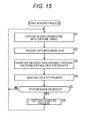
- This sending process starts, for example, when the operation part 46 is operated so as to capture and send image data.
- the control part 47 then performs the sending process by controlling the capture part 41 through the capture adjusting part 45 according to an operating signal from the operation part 46.
- the capture part 41 obtains image data input externally and supplies the data to the encoding part 42 under the control of the control part 47 and in synchronization with the capture timing Vblank adjusted by the capture adjusting process of step S6 to be described below.
- the capture part 41 in synchronization with the predetermined capture timing Vblank, for example, obtains image data input externally and supplies the data to the encoding part 42.
- step S2 the encoding part 42 performs the encoding process to encode the image data from the capture part 41 and supplies the encoded data obtained through the encoding process to the packetizing part 43.
- step S3 the packetizing part 43 packetizes (converts) the encoded data from the encoding part 42 into multiple RTP packets and outputs the packets to the RTP communication part 44.
- step S4 the RTP communication part 44, in accordance with RTP, adds to the RTP packets from the packetizing part 43 the time or the like for sending the RTP packets, for example, to the receiving device 22 as a timestamp.
- the RTP communication part 44 then sends the RTP packets, with the timestamp added, through the network 23 to the receiving device 22.
- step S5 the RTP communication part 44 determines whether the RTCP message including the adjustment quantities Zforward and Zbackward has been received through the network 23 from the receiving device 22. If it is determined that the message has not been received, the process reverts to step S1 and, from then on, the process is performed in a similar manner.
- the RTP communication part 44 determines in step S5 that the RTCP message including the adjustment quantities Zforward and Zbackward has been received through the network 23 from the receiving device 22, the RTCP message is supplied to the capture adjusting part 45.
- step S6 the capture adjusting part 45 performs the capture adjusting process to adjust the capture timing Vblank based on the RTCP message from the RTP communication part 44. Also in step S6, the capture adjusting part 45, after the completion of the capture adjusting process, reverts to step S1 of the process, and from then on, the process is performed in a similar manner. Note that the sending process is finished when, for example, the operation part 46 is operated by a user so as to stop sending image data.
- the capture adjusting part 45 is supplied with the RTCP message by the RTP communication part 44.
- step S21 the capture adjusting part 45 obtains (extracts), from the RTCP message supplied by the RTP communication part 44, the adjustment quantities Zforward and Zbackward that are included in the RTCP message.
- step S22 the capture adjusting part 45 determines whether the obtained adjustment quantity Zbackward is zero. If the adjustment quantity Zbackward is determined to be zero, the process moves on to step S23.
- step S23 the capture adjusting part 45 controls the capture part 41 so as to delay the capture timing Vblank of the capture part 41 by the obtained other adjustment quantity Zforward.
- the capture adjusting part 45 adjusts the current capture timing Vblank as shown in Fig. 8A so as to obtain the capture timing Vblank as shown in Fig. 8B .
- the capture part 41 thus captures each unit of the image data in synchronization with the adjusted capture timing Vblank as shown in Fig. 9A .
- the display control part 66 of the receiving device 22 hence displays the image data, as shown in Fig. 9B , at the display timing Vblank with the necessary time Y that is reduced as much as possible to the extent that expression (3) is met.
- step S22 the capture adjusting part 45 determines whether the obtained adjustment quantity Zbackward is zero. If the adjustment quantity Zbackward is determined to be not zero, or in other words, if the adjustment quantity Zforward is determined to be zero, the process moves on to step S24.
- step S24 the capture adjusting part 45 controls the capture part 41 so as to advance the capture timing Vblank of the capture part 41 by the obtained other adjustment quantity Zbackward.
- the capture adjusting part 45 adjusts the current capture timing Vblank as shown in Fig. 11A so as to obtain the capture timing Vblank as shown in Fig. 11B .
- the capture part 41 thus captures each unit of the image data in synchronization with the adjusted capture timing Vblank as shown in Fig. 12A .
- the display control part 66 of the receiving device 22 hence displays the image data, as shown in Fig. 12B , at the display timing Vblank that meets expression (3).
- step S1 the capture part 41 captures each unit of the image data in synchronization with the capture timing Vblank adjusted through the capture adjusting process.
- the capture adjusting part 45 adjusts the capture timing Vblank in step S24 so as to meet expression (3).
- the receiving device 22 therefore, can restrain a situation where a disturbance or the like is generated in the image because a part of the image is skipped.
- the capture adjusting part 45 adjusts the capture timing Vblank in step S23 so as to reduce the necessary time Y as much as possible to the extent that expression (3) is met.
- the overall time taken from the write start time to the display timing is reduced for the odd-numbered field image n odd and the even-numbered field image n even , enabling the image to be displayed with minimized low delay.
- the adjustment quantity calculating process starts, for example, when the RTP packets are sent through the network 23 from the sending device 21.
- the RTP communication part 61 receives the RTP packets sent through the network 23 from the RTP communication part 44 and supplies the packets to the packet assembling part 62.
- the packet assembling part 62 assembles the RTP packets from the RTP communication part 61 to generate the encoded data to be decoded and supplies the data to the decoding part 63.
- the decoding part 63 performs the decoding process for the encoded data from the packet assembling part 62 and supplies the resultant image data to the write control part 64.
- the decoding process corresponds to the encoding process performed by the encoding part 42.
- the write control part 64 supplies the image data (the odd-numbered field image and the even-numbered field image) from the decoding part 63 to the buffer 65 for storing (writing).
- the write control part 64 supplies the write start time Ts when the writing into the buffer 65 has started and the write end time Te when the writing has ended to the write information measuring part 68 for each even-numbered field image n even .
- the display control part 66 reads the odd-numbered field image and the even-numbered field image as the image data from the buffer 65 and allows the display part 67 to display the image data in synchronization with the predetermined display timing Vblank.
- step S41 based on the write start time Ts from the write control part 64 and the predetermined display timing Vblank, the write information measuring part 68 measures the write preparation time Xn for the even-numbered field image n even and supplies the write preparation time Xn to the write information storage part 69 for storage.
- step S42 based on the disclosure time Ts and the end time Te from the write control part 64, the write information measuring part 68 measures the buffer write time Pn for the even-numbered field image n even and supplies the buffer write time Pn to the write information storage part 69 for storage.
- step S43 the adjustment quantity calculating part 70 determines whether a time measured by a built-in timer part (not shown) has passed a predetermined time. If the time measured is determined to have not passed the predetermined time, the process reverts to step S41 and, from then on, the process is performed in a similar manner.
- step S43 If the adjustment quantity calculating part 70 determines in step S43 that the time measured has passed the predetermined time, the process moves on to step S44.
- step S44 the adjustment quantity calculating part 70 reads the write preparation time Xn from the write information storage part 69 and calculates the X distribution information representing the distribution of the write preparation time Xn that has been read.
- step S45 the adjustment quantity calculating part 70 calculates the threshold Xth based on the X distribution information calculated in step S44.
- step S46 the adjustment quantity calculating part 70 calculates the necessary time Y based on the display interval Vblank Interval and the threshold Xth, using expression (2).
- step S47 the adjustment quantity calculating part 70 reads the buffer write time Pn from the write information storage part 69 and calculates the P distribution information representing the distribution of the buffer write time Pn that has been read.
- step S48 the adjustment quantity calculating part 70 calculates the threshold Pth according to the P distribution information calculated in step S47.
- step S49 the adjustment quantity calculating part 70 calculates the allowable delay time Yth based on the threshold Pth calculated in step S48 and the expected write time 1/60, using expression (1).
- step S50 the adjustment quantity calculating part 70 determines whether expression (3) is met based on the necessary time Y calculated in step S46 and the allowable delay time Yth calculated in step S49. If expression (3) is determined to be met, the process moves on to step S51.
- the adjustment quantity Zforward will be an adjustment quantity for adjusting the capture timing Vblank such that the necessary time Y is reduced to the extent that expression (3) is met.
- step S52 the adjustment quantity calculating part 70 sets the adjustment quantity Zbackward to zero and supplies the adjustment quantities Zforward and Zbackward to the RTP communication part 61.
- the process moves on to step S53.
- step S53 the RTP communication part 61 generates the RTCP message including the adjustment quantities Zforward and Zbackward from the adjustment quantity calculating part 70 and sends the message through the network 23 to the RTP communication part 44 of the sending device 21.
- step S50 if the adjustment quantity calculating part 70 determines, based on the necessary time Y calculated in step S46 and the allowable delay time Yth calculated in step S49, that expression (3) is not met, the process moves on to step S54.
- the adjustment quantity Zbackward will be an adjustment quantity for adjusting the capture timing Vblank such that expression (3) is met.
- step S55 the adjustment quantity calculating part 70 sets the adjustment quantity Zforward to zero and supplies the adjustment quantities Zforward and Zbackward to the RTP communication part 61.
- step S53 the process in step S53 described above is performed. The adjustment quantity calculating process is thus completed.
- the adjustment quantities Zforward and Zbackward are calculated, according to, for example, the write information of the even-numbered field image n even , so as to obtain the capture timing Vblank that allows expression (3) to be met.
- the capture timing Vblank is adjusted based on the adjustment quantities Zforward and Zbackward calculated through the adjustment quantity calculating process.
- the receiving device 22 therefore, writes the image with expression (3) met, and hence can restrain a situation where a disturbance or the like is generated in the image because a part of the image is skipped.
- the adjustment quantities Zforward and Zbackward for adjusting the capture timing Vblank are calculated so as to reduce the necessary time Y as much as possible to the extent that expression (3) is met.
- the overall time taken from the write start time to the display timing is reduced for the odd-numbered field image n odd and the even-numbered field image n even , enabling the image to be displayed with minimized low delay.
- the capture timing Vblank may be left unadjusted because expression (3) is met.
- the even-numbered field image n even will be displayed in synchronization with the display timing Vblank (n even ).
- the adjustment quantity calculating part 70 of the receiving device 22 calculates the adjustment quantities Zforward and Zbackward, but the adjustment quantity calculating part 70 may calculate just an adjustment quantity to be used for adjusting the capture timing. In this case, the RTP communication part 61 will not send an adjustment quantity that is set to zero but send just an adjustment quantity to be used for adjusting the capture timing.
- the capture adjusting part 45 of the sending device 21 will then use the adjustment quantity obtained through the RTP communication part 44 and the network 23 from the RTP communication part 61 to adjust the capture timing.
- the adjustment quantity calculating part 70 of the receiving device 22 calculates the adjustment quantities Zforward and Zbackward.
- the sending device 21, for example may be provided with the write information measuring part 68 through the adjustment quantity calculating part 70, so that the adjustment quantities Zforward and Zbackward are calculated at the sending device 21 side.
- the capture adjusting part 45 adjusts the capture timing based on the adjustment quantities Zforward and Zbackward calculated by the adjustment quantity calculating part 70 at the sending device 21 side.
- the write control part 64 of the receiving device 22 supplies the write start time Ts, the write end time Te, and the display timing Vblank for each unit of image data to the RTP communication part 61.
- the RTP communication part 61 will then supply the write start time Ts, the write end time Te, and the display timing Vblank from the write control part 64 through the network 23 to the write information measuring part 68 at the sending device 21 side.
- the sending device 21 is provided with the write information measuring part 68 through the adjustment quantity calculating part 70
- the receiving device 22 may not be provided with the write information measuring part 68 through the adjustment quantity calculating part 70.
- the necessary time Y and the allowable delay time Yth are calculated based on the write information of the even-numbered field image n even .
- the necessary time Y and the allowable delay time Yth may also be calculated based on, for example, the write information of the odd-numbered field image n odd as shown in Fig. 18 .
- the necessary time Y and the allowable delay time Yth may be calculated based on, for example, the write information of the odd-numbered field image n odd and the write information of the even-numbered field image n even .
- the display part 67 may use a progressive image (frame image) as each image and calculates the necessary time Y and the allowable delay time Yth based on the write information of the progressive image as shown in Fig. 19 .
- the adjustment quantity calculating part 70 when generating the X distribution information representing the distribution of the write preparation time Xn as shown in Fig. 4 , the adjustment quantity calculating part 70 generates the X distribution information with the frequency of the write preparation time Xn at 1 regardless of the timing of the measurement of the write preparation time Xn.
- the adjustment quantity calculating part 70 may generate the X distribution information with the frequency of the write preparation time Xn added more as the measurement timing is more recent. This is because, the more recently the write preparation time Xn is measured, the more accurately the write preparation time for the image to be received is likely represented.
- the adjustment quantity calculating part 70 thus will be able to calculate the necessary time Y and the allowable delay time Yth for the image to be received more accurately based on such X distribution information and such P distribution information. Hence, the adjustment quantity calculating part 70 will be able to calculate a more accurate adjustment quantity based on the result of a comparison between the necessary time Y and the allowable delay time Yth (the result of the determination whether expression (3) is met).
- the capture adjusting part 45 of the sending device 21, therefore, will be able to adjust the capture timing Vblank more appropriately based on the adjustment quantity calculated by the adjustment quantity calculating part 70.
- the series of processes described above may be executed by hardware or software.
- a program constituting the software is installed through a program recording medium into a computer integrated in special hardware, or, for example, into a general-purpose computer that can execute different functions with different programs installed.
- Fig. 20 is a block diagram of an exemplary configuration of hardware for a computer that executes, by a program, the series of processes described above.
- a CPU (Central Processing Unit) 201 executes different processes according to the program stored in a ROM (Read Only Memory) 202 or a storage part 208.
- a RAM (Random Access Memory) 203 stores the program to be executed by the CPU 201 and data as appropriate.
- the CPU 201, the ROM 202, and the RAM 203 are mutually connected through a bus 204.
- the CPU 201 is also connected to an input/output interface 205 through the bus 204.
- the input/output interface 205 is connected to an input part 206 including a keyboard, a mouse, a microphone, and the like and to an output part 207 including a display, a speaker, and the like.
- the CPU 201 executes different processes corresponding to an instruction input from the input part 206.
- the CPU 201 then outputs a result of the processes to the output part 207.
- the storage part 208 connected to the input/output interface 205 includes, for example, hardware, and stores the program to be executed by the CPU 201 and different types of data.
- the communication part 209 communicates with an external device through a network such as the Internet and a local area network.
- the program may be obtained through the communication part 209 and stored in the storage part 208.
- a drive 210 connected to the input/output interface 205 drives a removable medium 211 such as a magnetic disk, an optical disk, a magneto-optical disk, or a semiconductor memory when mounted and obtains the program, data, and the like stored therein.
- the obtained program and data are transferred to the storage part 208 as needed for storage.
- a recording medium to record (store) the program that is to be installed in the computer and made executable by the computer includes, as shown in Fig. 20 , the removable medium 211 that is a packaged medium including a magnetic disk (including a flexible disk), an optical disk (including a CD-ROM (Compact Disc-Read Only Memory) and a DVD (Digital Versatile Disc)), a magneto-optical disk (including an MD (Mini-Disc)), a semiconductor memory or the like, a ROM 202 storing the program temporarily or permanently, a hard disk constituting the storage part 208, or the like.
- the program is recorded into the recording medium through the communication part 209 that is an interface such as a router and a modem as needed by using a wired or wireless communication medium such as a local area network, the Internet, and digital satellite broadcasting.
- a system refers to equipment including multiple devices.
Abstract
Description
- The present disclosure relates to a sending device, a sending method, and a program. More particularly, the present disclosure relates to a sending device, a sending method, and a program that can restrain a disturbance or the like of an image, the disturbance or the like being generated when the image, transmitted from a sending device through a data transmission channel such as a network, for example, is displayed with low delay.
- In recent years, remote surgeries have been performed where, for example, a surgery is performed on a patient in a remote location by operating robot arms. During such a remote surgery, a doctor performing the surgery operates robot arms while looking at moving images obtained by taking images from the ongoing surgery; thus it is desirable that the moving images be transmitted with low delay of several frames (or several fields) or less (substantially in real time).
- Given such a situation, encoding techniques have been proposed to take several lines of each picture constituting a moving image as a unit of block data and to encode (compress) each unit of block data by wavelet transform (see
Patent Document 1, for example). - According to this type of encoding technique, a sending device starts encoding the block data without waiting for the input of the complete units of the block data within a picture and sends the resultant encoded data. A receiving device starts decoding (expanding) the encoded data before receiving the complete encoded data from the sending device.
- The receiving device thus can decode the encoded data and make the picture displayable in time for a predetermined display timing when a picture should be displayed. Hence, the receiving device can allow a monitor to display the picture in synchronization with the display timing.
- Patent Document 1: Japanese Patent Application Laid-Open No.
2007-311924 - Congestion of a data transmission channel such as a network, however, may prevent the sending device from sending a moving image with low delay of several frames or less.
- In this case, the receiving device cannot make a picture displayable in time for the predetermined display timing. The picture that has not been made displayable in time for the display timing may not be, for example, displayed on the monitor and be skipped, possibly causing a disturbance or the like to an image to be displayed on the monitor.
- The present disclosure has been provided in light of such a situation, and is to restrain a disturbance or the like of an image, the disturbance or the like being generated when the image, transmitted from a data transmission channel, is displayed with low delay.
- A sending device according to an aspect of the present disclosure includes an obtaining part that obtains an adjustment quantity for adjusting a capture timing to start capturing an image; a capture adjusting part that adjusts the capture timing based on the adjustment quantity; a capture part that captures the image in synchronization with the adjusted capture timing; and a sending part that sends the captured image to a receiving device.
- The receiving device includes a holding part that temporarily holds the image, writes into the holding part the image received from the sending part, and allows the image written in the holding part to be displayed in synchronization with a predetermined display timing, and the obtaining part may obtain the adjustment quantity calculated based on a result of comparison between an allowable delay time representing a delay time allowed when the writing of the image into the holding part is not completed within a predetermined needed time from a write start time when the writing has started, and a necessary time at least taken from the write start time for the image that has been written with a delay time of the allowable delay time or less to the display timing.
- A first calculating part that calculates the allowable delay time, a second calculating part that calculates the necessary time, a comparing part that compares the allowable delay time and the necessary time, and an adjustment quantity calculating part that calculates the adjustment quantity based on a comparison result of the comparing part may be further included, and the obtaining part may obtain the adjustment quantity calculated by the adjustment quantity calculating part.
- If a comparison result is obtained to show that the necessary time is longer than the allowable delay time, the adjustment quantity calculating part may calculate the adjustment quantity for adjusting the capture timing such that the necessary time is reduced to an extent that a condition that the necessary time is longer than the allowable delay time is met.
- If a comparison result is obtained to show that the necessary time is not longer than the allowable delay time, the adjustment quantity calculating part may calculate the adjustment quantity for adjusting the capture timing such that the necessary time becomes longer than the allowable delay time.
- The obtaining part may obtain the adjustment quantity by receiving the same from the receiving device.
- A first measuring part that measures a write time taken to write the image into the holding part of the receiving device may be further included, and the first calculating part may calculate the allowable delay time based on a distribution of the write time.
- A second measuring part that measures a write preparation time taken to start writing the image into the holding part of the receiving device may be further included, and the second calculating part may calculate the necessary time based on a distribution of the write preparation time.
- A sending method according to an aspect of the present disclosure is for a sending device that captures and sends an image, the sending method including the steps of, by the sending device: obtaining an adjustment quantity for adjusting a capture timing to start capturing the image; adjusting the capture timing based on the adjustment quantity; capturing the image in synchronization with the adjusted capture timing; and sending the captured image to a receiving device.
- A program according to an aspect of the present disclosure is for allowing a computer to function as: an obtaining part that obtains an adjustment quantity for adjusting a capture timing to start capturing an image; a capture adjusting part that adjusts the capture timing based on the adjustment quantity; a capture part that captures the image in synchronization with the adjusted capture timing; and a sending control part that allows the captured image to be sent to a receiving device.
- According to an aspect of the present disclosure, an adjustment quantity for adjusting a capture timing to start capturing an image is obtained, the capture timing is adjusted based on the adjustment quantity, the image is captured in synchronization with the adjusted capture timing, and the captured image is sent to a receiving device.
- According to the present disclosure, a disturbance or the like of an image can be restrained, the disturbance or the like being generated when the image, transmitted from a data transmission channel, is displayed with low delay.
-
-
Fig. 1 is a block diagram of an exemplary configuration of a sending/receiving system according to the present disclosure. -
Fig. 2 is a graph of an example of displaying of an image in synchronization with a display timing. -
Fig. 3 is a graph of an exemplary method of measuring write information. -
Fig. 4 is a graph of an exemplary distribution of a write preparation time. -
Fig. 5 is a graph of an exemplary distribution of a buffer write time. -
Fig. 6 is a graph of an exemplary method of calculating a necessary time and an allowable delay time. -
Figs. 7A and 7B are first graphs of an exemplary case where a write start time to start writing an image changes depending on a capture timing. -
Figs. 8A and 8B are first graphs of an example of adjusting a capture timing. -
Figs. 9A and 9B are first graphs of an exemplary case where the write start time to start writing the image has changed due to the adjusted capture timing. -
Figs. 10A and 10B are second graphs of an exemplary case where the write start time to start writing the image changes depending on the capture timing. -
Figs. 11A and 11B are second graphs of an example of adjusting the capture timing. -
Figs. 12A and 12B are second graphs of an exemplary case where the write start time to start writing the image has changed due to the adjusted capture timing. -
Fig. 13 is a first graph of an example of varying of a transmitting time. -
Fig. 14 is a second graph of an example of varying of the transmitting time. -
Fig. 15 is a flow chart for describing a sending process performed by the sending device. -
Fig. 16 is a flow chart for describing a capture adjusting process in step S6 inFig. 15 . -
Fig. 17 is a flow chart for describing an adjustment quantity calculating process performed by the receiving device. -
Fig. 18 is a graph of an exemplary method of measuring write information of an odd-numbered field image. -
Fig. 19 is a graph of an exemplary method of measuring the write information of a progressive image. -
Fig. 20 is a block diagram of an exemplary configuration of a computer. - An embodiment of the present disclosure (hereinafter referred to as the present embodiment) will now be described below. Note that the description will be in the following order.
- 1. The present embodiment (an example of restraining of a disturbance or like of an image by adjusting a capture timing Vblank)
- 2. Exemplary variations
-
Fig. 1 illustrates a sending/receiving system according to the present disclosure. - This sending/receiving system includes a sending
device 21, a receivingdevice 22, and anetwork 23 such as the Internet. - In this sending/receiving system, the sending
device 21, for example, adjusts a capture timing Vblank to start capturing (obtaining) an image and sends the image captured at the adjusted capture timing to the receivingdevice 22. - This allows the receiving
device 22 to display the image received from the sendingdevice 21 with low delay without a disturbance or the like. - The sending
device 21 includes acapture part 41, anencoding part 42, a packetizingpart 43, an RTP (real-time transport protocol)communication part 44, acapture adjusting part 45, anoperation part 46, and acontrol part 47. - The
capture part 41, in synchronization with the capture timing Vblank adjusted by thecapture adjusting part 45, obtains (captures) image data externally input (corresponding to Video IN) and supplies the image data to theencoding part 42. As the image data, a frame image including multiple lines, for example, may be used. As another example, a field image including either odd-numbered lines or even-numbered lines among multiple lines may be used. - The present embodiment will be described with reference to
Figs. 1 to 18 with an assumption that a field image is used as the image data. In this case, thecapture part 41, in synchronization with the capture timing Vblank adjusted by thecapture adjusting part 45, obtains an odd-numbered field image and an even-numbered field image alternately as the image data and supplies the image data to theencoding part 42. - Here, the odd-numbered field image refers to a field image consisting of odd-numbered lines among the multiple lines. The even-numbered field image refers to a field image consisting of even-numbered lines among the multiple lines.
- Note that the use of a frame image as the image data will be described with reference to
Fig. 19 . - The
encoding part 42 performs an encoding process to encode the image data from thecapture part 41 and supplies the encoded data obtained through the encoding process to the packetizingpart 43. - As the encoding process, a wavelet encoding process to encode image data, for example, by using wavelet transform to compress the image data may be used.
- The packetizing
part 43 packetizes (converts) the encoded data from theencoding part 42 into multiple RTP packets and outputs the RTP packets to theRTP communication part 44. An RTP packet refers to a packet in accordance with RTP described in IETF RFC3550. - The
RTP communication part 44, in accordance with RTP, adds to the RTP packets from the packetizingpart 43 the time or the like for sending the RTP packets, for example, to the receivingdevice 22 as a timestamp. TheRTP communication part 44 then sends the RTP packets, with the timestamp added, through thenetwork 23 to the receivingdevice 22. - In addition, the
RTP communication part 44, in accordance with RTP, receives an RTCP message supplied through thenetwork 23 from the receivingdevice 22 and supplies the message to thecapture adjusting part 45. - Here, the RTCP message includes adjustment quantities Zforward and Zbackward for adjusting the capture timing Vblank. The adjustment quantities Zforward and Zbackward are, for example, calculated and sent by the receiving
device 22. One of the adjustment quantities Zforward and Zbackward is set to, for example, zero. - The
capture adjusting part 45 performs a capture adjusting process to adjust the capture timing Vblank of thecapture part 41 based on the adjustment quantities Zforward and Zbackward from theRTP communication part 44. - In other words, for example, if the adjustment quantity Zforward = 0, the
capture adjusting part 45 makes an adjustment such that the capture timing Vblank is advanced by the adjustment quantity Zbackward. If, for example, the adjustment quantity Zbackward = 0, thecapture adjusting part 45 makes an adjustment such that the capture timing Vblank is delayed by the adjustment quantity Zforward. The capture adjusting process performed by thecapture adjusting part 45 will be described in detail below with reference toFig. 16 . - The
operation part 46 includes operating buttons and the like to be operated by a user and supplies an operating signal according to the user operation to thecontrol part 47. - The
control part 47 controls thecapture part 41, theencoding part 42, the packetizingpart 43, and theRTP communication part 44 based on, for example, an operating signal from theoperation part 46. - The receiving
device 22 includes anRTP communication part 61, apacket assembling part 62, adecoding part 63, awrite control part 64, abuffer 65, adisplay control part 66, adisplay part 67, a writeinformation measuring part 68, a writeinformation storage part 69, an adjustmentquantity calculating part 70, anoperation part 71, and acontrol part 72. - The
RTP communication part 61 receives the RTP packets sent from theRTP communication part 44 through thenetwork 23 and supplies them to thepacket assembling part 62. TheRTP communication part 61 generates, based on adjustment quantities from the adjustmentquantity calculating part 70, an RTCP message including the adjustment quantities, and sends the message through thenetwork 23 to theRTP communication part 44. - The
packet assembling part 62 assembles the RTP packets from theRTP communication part 61 to generate encoded data to be decoded and supplies the data to thedecoding part 63. - The
decoding part 63 performs a decoding process for the encoded data from thepacket assembling part 62 and supplies the resultant image data to thewrite control part 64. The decoding process corresponds to the encoding process performed by theencoding part 42. As the decoding process, a decoding process of decoding and expanding by using inverse transform of wavelet transform, for example, is used. - The
write control part 64 supplies the image data from thedecoding part 63 to thebuffer 65 for storing (writing). In addition, thewrite control part 64 supplies a write start time Ts when writing into thebuffer 65 has started and a write end time Te when the writing has ended to the writeinformation measuring part 68 for each unit of image data. - The
buffer 65 temporarily stores the image data from thewrite control part 64. - The
display control part 66 reads the image data from thebuffer 65 and supplies the data to thedisplay part 67. Thedisplay control part 66 then allows thedisplay part 67 to display the image data read from thebuffer 65 in synchronization with a predetermined display timing Vblank. -
Fig. 2 illustrates an example where thedisplay control part 66 allows each unit of image data to be displayed at the predetermined display timing Vblank. - The image data is, for example, a field image, which is one of an odd-numbered field image nodd consisting of odd-numbered lines among the multiple lines or an even-numbered field image neven consisting of even-numbered lines among the multiple lines.
- In
Fig. 2 , the horizontal axis represents time; the vertical axis represents a line number for a line displayed at a corresponding time. An assumption here is that the odd-numbered field image nodd and the even-numbered field image neven each consist of 540 lines. - A display timing Vblank (nodd) represents a time to start displaying the odd-numbered field image nodd. A display timing Vblank (neven) represents a time to start displaying the even-numbered field image neven.
- The
display control part 66 reads the odd-numbered field image nodd from thebuffer 65 and allows thedisplay part 67 to display the image in synchronization with the predetermined display timing Vblank (nodd). Thedisplay control part 66 also reads the even-numbered field image neven from thebuffer 65 and allows thedisplay part 67 to display the image in synchronization with the predetermined display timing Vblank (uneven). - The
display part 67 displays each unit of image data with, for example, an interlacing scheme. In other words, for example, thedisplay part 67 displays the odd-numbered field image nodd and the even-numbered field image neven alternately as a unit of image data under the control of thedisplay control part 66. Thedisplay part 67 may be a component of the receivingdevice 22 as shown inFig. 1 , or may be separate from the receivingdevice 22 and provided independently. In this case, thedisplay control part 66 within the receivingdevice 22 is connected to thedisplay part 67 provided outside the receivingdevice 22 through, for example, a cable or the like. - The write
information measuring part 68 measures write information of the even-numbered field image neven written in thebuffer 65. The writeinformation measuring part 68 may measure write information of the odd-numbered field image nodd written in thebuffer 65 in lieu of, or together with, the write information of the even-numbered field image neven. This will be described below with reference toFig. 18 . - If, for example, the frame image is used as the image data and the
display part 67 is designed to display each unit of image data through a progressive scheme, the writeinformation measuring part 68 will take the frame image as each unit of image data and measure write information of the frame image. This will be described below with reference toFig. 19 . - The description below assumes that the write
information measuring part 68 measures write information of the even-numbered field image neven written in thebuffer 65. - The write
information measuring part 68 measures, as the write information of the even-numbered field image neven written in thebuffer 65, a write preparation time Xn that is a time necessary until the writing of the even-numbered field image neven starts and a buffer write time Pn that is a time taken for the writing of the even-numbered field image neven, for example. -
Fig. 3 illustrates an example where the writeinformation measuring part 68 measures the write preparation time Xn and the buffer write time Pn for the even-numbered field image neven. - Here, in
Fig. 3 , the write start time Ts represents the time when the writing of the even-numbered field image neven into thebuffer 65 has started. The write end time Te represents the time when the writing of the even-numbered field image neven into thebuffer 65 has ended. - Note that the write
information measuring part 68 is supplied by thewrite control part 64 with the write start time Ts and the write end time Te for the even-numbered field image neven. - As shown in
Fig. 3 , the writeinformation measuring part 68 measures the write preparation time Xn (= Vblank (n - 1even) - Ts) based on the write start time Ts from thewrite control part 64 and a predetermined display timing Vblank (n-leven). - In addition, for example, the write
information measuring part 68 measures, as shown inFig. 3 , the buffer write time Pn (= Te - Ts) based on the write start time Ts and the write end time Te from thewrite control part 64. - The write
information measuring part 68 supplies the write preparation time Xn and the buffer write time Pn measured for each even-numbered field image neven to the writeinformation storage part 69 for storage. - With reference to
Fig. 1 again, the writeinformation storage part 69 stores the write preparation time Xn and the buffer write time Pn from the writeinformation measuring part 68 as the write information. - The adjustment
quantity calculating part 70 performs, based on the write information stored in the writeinformation storage part 69, an adjustment quantity calculating process to calculate the adjustment quantities Zforward and Zbackward for adjusting the capture timing Vblank at thecapture part 41 of the sendingdevice 21. Note that the adjustment quantity calculating process will be described in detail with reference, for example, toFig. 17 . - The adjustment
quantity calculating part 70 supplies adjustment quantities Zforward and Zbackward calculated through the adjustment quantity calculating process to theRTP communication part 61. - The
operation part 71 includes operating buttons and the like to be operated by a user and supplies an operating signal according to the user operation to thecontrol part 72. - The
control part 72 controls theRTP communication part 61, thepacket assembling part 62, thedecoding part 63, thewrite control part 64, thedisplay control part 66, the writeinformation measuring part 68, and the adjustmentquantity calculating part 70 based on, for example, an operating signal from theoperation part 71. - Now, with reference to
Figs. 4 to 12 , the adjustment quantity calculating process performed by the adjustmentquantity calculating part 70 of the receivingdevice 22 and the capture adjusting process performed by thecapture adjusting part 45 of the sendingdevice 21 will be described. -
Fig. 4 illustrates an exemplary distribution of the write preparation time Xn stored in the writeinformation storage part 69. - In
Fig. 4 , the horizontal axis represents the write preparation time Xn; the vertical axis represents the frequency of the write preparation time Xn. - The adjustment
quantity calculating part 70 generates, based on the write preparation time Xn stored in the writeinformation storage part 69, X distribution information representing a distribution of the write preparation time Xn as shown inFig. 4 . - The adjustment
quantity calculating part 70 then calculates, based on the X distribution information of the write preparation time Xn, a threshold Xth for distinguishing the write preparation time Xn occupying an upper α (where α = 95, for example) percent from the write preparation time Xn occupying the remaining lower (100 - α) percent, with the write preparation time Xn sorted in an ascending order. - Here, the threshold Xth is the maximum value or more of the write preparation time Xn occupying the upper α (where α = 95, for example) percent and is less than the minimum value of the write preparation time Xn occupying the lower (100 - α) percent, with the write preparation time Xn sorted in an ascending order. The value α is, for example, predetermined by user operation.
-
Fig. 5 illustrates an exemplary distribution of the buffer write time Pn stored in the writeinformation storage part 69. - In
Fig. 5 , the horizontal axis represents the buffer write time Pn; the vertical axis represents the frequency of the buffer write time Pn. - The adjustment
quantity calculating part 70 generates, based on the multiple buffer write times Pn stored in the writeinformation storage part 69, P distribution information representing a distribution of the buffer write time Pn as shown inFig. 5 . - The adjustment
quantity calculating part 70 then calculates, based on the P distribution information of the buffer write time Pn, a threshold Pth for distinguishing the buffer write time Pn occupying an upper α percent from the buffer write time Pn occupying the lower (100 - α) percent, with the buffer write time Pn sorted in an ascending order. - Here, the threshold Pth is the maximum value or more of the buffer write time Pn occupying the upper α and is less than the minimum value of the buffer write time Pn occupying the lower (100 - α) percent, with the buffer write time Pn sorted in the ascending order.
-
Fig. 6 illustrates an example where the adjustmentquantity calculating part 70 calculates an allowable delay time Yth based on the threshold Pth, and a necessary time Y based on the threshold Xth. - The adjustment
quantity calculating part 70 calculates, based on the threshold Pth calculated from the P distribution information of the buffer write time Pn as shown inFig. 6 , the allowable delay time Yth with expression (1).
- Here, the allowable delay time Yth refers to a delay time used when a writing of the even-numbered field image neven cannot be completed within a predetermined expected
write time 1/60 from the write start time Ts when the writing has started. The allowable delay time Yth is a delay time allowed to display the even-numbered field image neven without a disturbance or the like with a probability of at least α percent. - α Note that the expected
write time 1/60 refers to a write time of the even-numbered field image neven (or the odd-numbered field image nodd) expected when there is no delay or the like in data writing at thewrite control part 64. - The expected
write time 1/60 is determined depending on, for example, the time taken to display the even-numbered field image neven (or the odd-numbered field image nodd). In the current case, thedisplay part 67 is configured to display the odd-numbered field image and the even-numbered field image each for adisplay time 1/60. Hence, for example, the expected write time is determined similarly to be 1/60. When thedisplay part 67 displays the odd-numbered field image and the even-numbered field image each for adisplay time 1/m, the expected write time is, for example, 1/m. - The adjustment
quantity calculating part 70, for example, calculates, based on the threshold Xth calculated from the X distribution information of the write preparation time Xn, a necessary time Y for the even-numbered field image neven to be received with a probability of α percent, or in other words, the even-numbered field image neven to be written with a delay time of the allowable delay time Yth or less. - Here, the necessary time Y refers to a time at least taken from the write start time Ts to the display timing (neven) for the even-numbered field image neven to be written into the
buffer 65 with a delay time of the allowable delay time Yth or less. - In other words, for example, the adjustment
quantity calculating part 70 calculates, based on a display interval Vblank Interval between the display timing Vblank (n-1even) and the display timing (neven), and the threshold Xth as shown inFig. 6 , the necessary time Y with expression (2) below.
- The adjustment
quantity calculating part 70 determines whether the even-numbered field image neven can be displayed without a disturbance or the like with a probability of at least α percent based on whether the calculated necessary time Y meets expression (3) below.
- The adjustment
quantity calculating part 70 then, based on the result of the determination, calculates the adjustment quantities Zforward and Zbackward. In other words, for example, the adjustmentquantity calculating part 70 calculates the adjustment quantity Zforward (= Y - Yth) as shown inFig. 6 , if expression (3) is met. The adjustmentquantity calculating part 70 then supplies the calculated adjustment quantity Zforward and the adjustment quantity Zbackward set to 0 to theRTP communication part 61. - Now, with reference to
Figs. 7 to 9 , the adjustment quantity calculating process and the capture adjusting process, both of which are performed if expression (3) is met, will be described. The adjustment quantity calculating process is performed by the adjustmentquantity calculating part 70 and the capture adjusting process is performed by thecapture adjusting part 45. - Note that the following description assumes that the display timing at the receiving
device 22 side is in synchronization with the capture timing at the sendingdevice 21 side; however, the display timing may not be in synchronization with the capture timing. - As shown in
Fig. 7A , the sendingdevice 21 side starts capturing the even-numbered field image neven in synchronization with a capture timing Vblank (neven). - If expression (3) is met, as shown in
Fig. 7B , the receivingdevice 22 side starts writing the even-numbered field image neven into thebuffer 65 at the write start time Ts. A line (i) with the line number i then will be written into thebuffer 65 before the display timing of the line (i). - In this case, the adjustment
quantity calculating part 70 calculates the adjustment quantity Zforward (= Y - Yth) as shown inFig. 7B and sets the adjustment quantity Zbackward to zero, and supplies the adjustment quantities Zforward and Zbackward to theRTP communication part 61. TheRTP communication part 61 generates an RTCP message including the adjustment quantities Zforward and Zbackward from the adjustmentquantity calculating part 70, and sends the message through thenetwork 23 to theRTP communication part 44 of the sendingdevice 21. - The
RTP communication part 44 of the sendingdevice 21 supplies the RTCP message received through thenetwork 23 from theRTP communication part 61 to thecapture adjusting part 45. - The
capture adjusting part 45 adjusts the capture timing Vblank of thecapture part 41 based on the adjustment quantities Zforward and Zbackward included in the RTCP message from theRTP communication part 44. - In the current case, the adjustment quantity Zbackward included in the RTCP message is zero. Accordingly, the
capture adjusting part 45 adjusts the current capture timing Vblank as shown inFig. 8A so as to obtain the capture timing Vblank as shown inFig. 8B by delaying the current capture timing Vblank by the adjustment quantity Zforward. - Hence, the
capture part 41 will capture an external even-numbered field image neven with the adjusted capture timing Vblank that is delayed by the adjustment quantity Zforward as shown inFig. 9A , for example. - The
write control part 64 of the receivingdevice 22 thus will start writing the even-numbered field image neven at the write start time Ts' (= Ts + Zforward) that is delayed by the adjustment quantity Zforward as shown inFig. 9B . In this case, the necessary time Y is reduced limitlessly to an extent that expression (3) is met. - Now, with reference to
Figs. 10 to 12 , the adjustment quantity calculating process and the capture adjusting process, both of which are performed if expression (3) is not met, will be described. The adjustment quantity calculating process is performed by the adjustmentquantity calculating part 70 and the capture adjusting process is performed by thecapture adjusting part 45. - Note that, as shown in
Fig. 10A , the sendingdevice 21 side starts capturing the even-numbered field image neven in synchronization with the capture timing Vblank (neven). - If expression (3) is not met, the receiving
device 22 side starts writing the even-numbered field image neven into thebuffer 65 at the write start time Ts as shown inFig. 10B . Given a line (i) with the line number i, a line with the line number L or beyond (i ≥ L), for example, will be written into thebuffer 65 after the display timing of the line (i ≥ L). - Here, the line with the line number L refers to, in
Fig. 10B , a line when the thick broken line representing the write timing of each line of the even-numbered field image neven and the solid line representing the display timing of each line of the even-numbered field image neven cross. - In this case, the adjustment
quantity calculating part 70 calculates, as shown inFig. 10B , the adjustment quantity Zbackward (= Yth - Y) and sets the adjustment quantity Zforward to zero, and supplies the adjustment quantities Zforward and Zbackward to theRTP communication part 61. TheRTP communication part 61 generates an RTCP message including the adjustment quantities Zforward and Zbackward from the adjustmentquantity calculating part 70, and sends the message through thenetwork 23 to theRTP communication part 44 of the sendingdevice 21. - The
RTP communication part 44 of the sendingdevice 21 supplies the RTCP message, received throughnetwork 23 from theRTP communication part 61, to thecapture adjusting part 45. - The
capture adjusting part 45 adjusts the capture timing Vblank of thecapture part 41 based on the adjustment quantities Zforward and Zbackward included in the RTCP message from theRTP communication part 44. - In the current case, the adjustment quantity Zforward included in the RTCP message is zero. Accordingly, the
capture adjusting part 45 adjusts the current capture timing Vblank as shown inFig. 11A so as to obtain the capture timing Vblank as shown inFig. 11B by advancing the current capture timing Vblank by the adjustment quantity Zbackward. - The
capture part 41 thus, for example, will capture an external even-numbered field image neven at the adjusted capture timing Vblank that is advanced by the adjustment quantity Zforward as shown inFig. 12A . - The
write control part 64 of the receivingdevice 22 thus will start writing the even-numbered field image neven at the write start time Ts' (Ts - Zbackward) that is advanced from the write start time Ts by the adjustment quantity Zbackward as shown inFig. 12B . In this case, as shown inFig. 12B , expression (3) will be met. - Note that the adjustment
quantity calculating part 70 performs the adjustment quantity calculating process as appropriate. This is because the transmitting time of the image data varies depending on congestion and other situations of thenetwork 23, which brings about a state as shown inFigs. 7A and 7B or inFigs. 10A and 10B even with the adjusted capture timing Vblank. - Now,
Figs. 13 and14 each illustrate an example where the transmitting time varies depending on congestion and other situations of thenetwork 23. - In
Figs. 13 and14 , the vertical axis represents a packet number that stands for an RTP packet of the image data. The horizontal axis represents the time that is each taken for a "capture" process performed by thecapture part 41, an "encoding" process performed by theencoding part 42, a "packetizing" process performed by the packetizingpart 43, an RTP packet "transfer" process performed through thenetwork 23 between theRTP communication part 44 and theRTP communication part 61, a "packet assembling" process performed by thepacket assembling part 62, and a "decoding" process performed by thedecoding part 63. These processes are performed for the data constituting the image data. - As shown in
Figs. 13 and14 , the time taken for the "transfer" process will significantly vary depending on the situation of thenetwork 23. That is, if congestion of thenetwork 23 is relatively minor, the time taken for the "transfer" process will be short as shown inFig. 13 . If the congestion of thenetwork 23 is relatively major, the time taken for the "transfer" process will be long as shown inFig. 14 . - The time taken for the "transfer" process and consequently the transmitting time vary depending on the congestion and other situations of the
network 23, which in turn brings about a state as shown inFigs. 7A and 7B orFigs. 10A and 10B . Hence, the adjustmentquantity calculating part 70 needs to perform the adjustment quantity calculating process as appropriate. - The
capture adjusting part 45 then needs to adjust the capture timing Vblank of thecapture part 41 based on the adjustment quantities Zforward and Zbackward supplied from the adjustmentquantity calculating part 70 through theRTP communication part 61, thenetwork 23, and theRTP communication part 44. - Now, with reference to a flow chart in
Fig. 15 , a sending process performed by the sendingdevice 21 will be described. - This sending process starts, for example, when the
operation part 46 is operated so as to capture and send image data. Thecontrol part 47 then performs the sending process by controlling thecapture part 41 through thecapture adjusting part 45 according to an operating signal from theoperation part 46. - In other words, at step S1, the
capture part 41 obtains image data input externally and supplies the data to theencoding part 42 under the control of thecontrol part 47 and in synchronization with the capture timing Vblank adjusted by the capture adjusting process of step S6 to be described below. - Here, if the capture adjusting process of step S6 is not performed yet, the
capture part 41, in synchronization with the predetermined capture timing Vblank, for example, obtains image data input externally and supplies the data to theencoding part 42. - In step S2, the
encoding part 42 performs the encoding process to encode the image data from thecapture part 41 and supplies the encoded data obtained through the encoding process to the packetizingpart 43. - In step S3, the packetizing
part 43 packetizes (converts) the encoded data from theencoding part 42 into multiple RTP packets and outputs the packets to theRTP communication part 44. - In step S4, the
RTP communication part 44, in accordance with RTP, adds to the RTP packets from the packetizingpart 43 the time or the like for sending the RTP packets, for example, to the receivingdevice 22 as a timestamp. TheRTP communication part 44 then sends the RTP packets, with the timestamp added, through thenetwork 23 to the receivingdevice 22. - In step S5, the
RTP communication part 44 determines whether the RTCP message including the adjustment quantities Zforward and Zbackward has been received through thenetwork 23 from the receivingdevice 22. If it is determined that the message has not been received, the process reverts to step S1 and, from then on, the process is performed in a similar manner. - If the
RTP communication part 44 determines in step S5 that the RTCP message including the adjustment quantities Zforward and Zbackward has been received through thenetwork 23 from the receivingdevice 22, the RTCP message is supplied to thecapture adjusting part 45. - In step S6, the
capture adjusting part 45 performs the capture adjusting process to adjust the capture timing Vblank based on the RTCP message from theRTP communication part 44. Also in step S6, thecapture adjusting part 45, after the completion of the capture adjusting process, reverts to step S1 of the process, and from then on, the process is performed in a similar manner. Note that the sending process is finished when, for example, theoperation part 46 is operated by a user so as to stop sending image data. - Now, with reference to the flow chart of
Fig. 16 , the capture adjusting process in step S6 ofFig. 15 will be described. - As described above, the
capture adjusting part 45 is supplied with the RTCP message by theRTP communication part 44. - In step S21, the
capture adjusting part 45 obtains (extracts), from the RTCP message supplied by theRTP communication part 44, the adjustment quantities Zforward and Zbackward that are included in the RTCP message. - In step S22, the
capture adjusting part 45 determines whether the obtained adjustment quantity Zbackward is zero. If the adjustment quantity Zbackward is determined to be zero, the process moves on to step S23. - In step S23, the
capture adjusting part 45 controls thecapture part 41 so as to delay the capture timing Vblank of thecapture part 41 by the obtained other adjustment quantity Zforward. - In other words, for example, the
capture adjusting part 45 adjusts the current capture timing Vblank as shown inFig. 8A so as to obtain the capture timing Vblank as shown inFig. 8B . - The
capture part 41 thus captures each unit of the image data in synchronization with the adjusted capture timing Vblank as shown inFig. 9A . Thedisplay control part 66 of the receivingdevice 22 hence displays the image data, as shown inFig. 9B , at the display timing Vblank with the necessary time Y that is reduced as much as possible to the extent that expression (3) is met. - In step S22, the
capture adjusting part 45 determines whether the obtained adjustment quantity Zbackward is zero. If the adjustment quantity Zbackward is determined to be not zero, or in other words, if the adjustment quantity Zforward is determined to be zero, the process moves on to step S24. - In step S24, the
capture adjusting part 45 controls thecapture part 41 so as to advance the capture timing Vblank of thecapture part 41 by the obtained other adjustment quantity Zbackward. - In other words, for example, the
capture adjusting part 45 adjusts the current capture timing Vblank as shown inFig. 11A so as to obtain the capture timing Vblank as shown inFig. 11B . Thecapture part 41 thus captures each unit of the image data in synchronization with the adjusted capture timing Vblank as shown inFig. 12A . Thedisplay control part 66 of the receivingdevice 22 hence displays the image data, as shown inFig. 12B , at the display timing Vblank that meets expression (3). - The capture adjusting process is thus completed and returned to step S6 in
Fig. 15 . The process reverts to step S1. In step S1, thecapture part 41 captures each unit of the image data in synchronization with the capture timing Vblank adjusted through the capture adjusting process. - As described above, according to the capture adjusting process, if expression (3) is not met, the
capture adjusting part 45 adjusts the capture timing Vblank in step S24 so as to meet expression (3). - The receiving
device 22, therefore, can restrain a situation where a disturbance or the like is generated in the image because a part of the image is skipped. - In addition, for example, even if expression (3) is met, the
capture adjusting part 45 adjusts the capture timing Vblank in step S23 so as to reduce the necessary time Y as much as possible to the extent that expression (3) is met. - Thus, the overall time taken from the write start time to the display timing is reduced for the odd-numbered field image nodd and the even-numbered field image neven, enabling the image to be displayed with minimized low delay.
- Now, with reference to the flow chart of
Fig. 17 , the adjustment quantity calculating process performed by the receivingdevice 22 will be described. - The adjustment quantity calculating process starts, for example, when the RTP packets are sent through the
network 23 from the sendingdevice 21. TheRTP communication part 61 receives the RTP packets sent through thenetwork 23 from theRTP communication part 44 and supplies the packets to thepacket assembling part 62. Thepacket assembling part 62 assembles the RTP packets from theRTP communication part 61 to generate the encoded data to be decoded and supplies the data to thedecoding part 63. Thedecoding part 63 performs the decoding process for the encoded data from thepacket assembling part 62 and supplies the resultant image data to thewrite control part 64. The decoding process corresponds to the encoding process performed by theencoding part 42. - The
write control part 64 supplies the image data (the odd-numbered field image and the even-numbered field image) from thedecoding part 63 to thebuffer 65 for storing (writing). In addition, thewrite control part 64 supplies the write start time Ts when the writing into thebuffer 65 has started and the write end time Te when the writing has ended to the writeinformation measuring part 68 for each even-numbered field image neven. - The
display control part 66 reads the odd-numbered field image and the even-numbered field image as the image data from thebuffer 65 and allows thedisplay part 67 to display the image data in synchronization with the predetermined display timing Vblank. - In step S41, based on the write start time Ts from the
write control part 64 and the predetermined display timing Vblank, the writeinformation measuring part 68 measures the write preparation time Xn for the even-numbered field image neven and supplies the write preparation time Xn to the writeinformation storage part 69 for storage. - In step S42, based on the disclosure time Ts and the end time Te from the
write control part 64, the writeinformation measuring part 68 measures the buffer write time Pn for the even-numbered field image neven and supplies the buffer write time Pn to the writeinformation storage part 69 for storage. - In step S43, the adjustment
quantity calculating part 70 determines whether a time measured by a built-in timer part (not shown) has passed a predetermined time. If the time measured is determined to have not passed the predetermined time, the process reverts to step S41 and, from then on, the process is performed in a similar manner. - If the adjustment
quantity calculating part 70 determines in step S43 that the time measured has passed the predetermined time, the process moves on to step S44. - In step S44, the adjustment
quantity calculating part 70 reads the write preparation time Xn from the writeinformation storage part 69 and calculates the X distribution information representing the distribution of the write preparation time Xn that has been read. - In step S45, the adjustment
quantity calculating part 70 calculates the threshold Xth based on the X distribution information calculated in step S44. - In step S46, the adjustment
quantity calculating part 70 calculates the necessary time Y based on the display interval Vblank Interval and the threshold Xth, using expression (2). - In step S47, the adjustment
quantity calculating part 70 reads the buffer write time Pn from the writeinformation storage part 69 and calculates the P distribution information representing the distribution of the buffer write time Pn that has been read. - In step S48, the adjustment
quantity calculating part 70 calculates the threshold Pth according to the P distribution information calculated in step S47. - In step S49, the adjustment
quantity calculating part 70 calculates the allowable delay time Yth based on the threshold Pth calculated in step S48 and the expectedwrite time 1/60, using expression (1). - In step S50, the adjustment
quantity calculating part 70 determines whether expression (3) is met based on the necessary time Y calculated in step S46 and the allowable delay time Yth calculated in step S49. If expression (3) is determined to be met, the process moves on to step S51. - In step S51, the adjustment
quantity calculating part 70 calculates the adjustment quantity Zforward (= Y - Yth) based on the necessary time Y and the allowable delay time Yth as shown inFig. 7B . The adjustment quantity Zforward will be an adjustment quantity for adjusting the capture timing Vblank such that the necessary time Y is reduced to the extent that expression (3) is met. - In step S52, the adjustment
quantity calculating part 70 sets the adjustment quantity Zbackward to zero and supplies the adjustment quantities Zforward and Zbackward to theRTP communication part 61. The process moves on to step S53. - Then, in step S53, the
RTP communication part 61 generates the RTCP message including the adjustment quantities Zforward and Zbackward from the adjustmentquantity calculating part 70 and sends the message through thenetwork 23 to theRTP communication part 44 of the sendingdevice 21. - In step S50, if the adjustment
quantity calculating part 70 determines, based on the necessary time Y calculated in step S46 and the allowable delay time Yth calculated in step S49, that expression (3) is not met, the process moves on to step S54. - In step S54, the adjustment
quantity calculating part 70 calculates the adjustment quantity Zbackward (= Yth - Y) based on the necessary time Y and the allowable delay time Yth as shown inFig. 10B . The adjustment quantity Zbackward will be an adjustment quantity for adjusting the capture timing Vblank such that expression (3) is met. - In step S55, the adjustment
quantity calculating part 70 sets the adjustment quantity Zforward to zero and supplies the adjustment quantities Zforward and Zbackward to theRTP communication part 61. The process moves on to step S53, where the process in step S53 described above is performed. The adjustment quantity calculating process is thus completed. - As described above, according to the adjustment quantity calculating process, the adjustment quantities Zforward and Zbackward are calculated, according to, for example, the write information of the even-numbered field image neven, so as to obtain the capture timing Vblank that allows expression (3) to be met.
- Then, in the capture adjusting process, the capture timing Vblank is adjusted based on the adjustment quantities Zforward and Zbackward calculated through the adjustment quantity calculating process.
- The receiving
device 22, therefore, writes the image with expression (3) met, and hence can restrain a situation where a disturbance or the like is generated in the image because a part of the image is skipped. - In addition, for example, according to the adjustment quantity calculating process, even if expression (3) is met, the adjustment quantities Zforward and Zbackward for adjusting the capture timing Vblank are calculated so as to reduce the necessary time Y as much as possible to the extent that expression (3) is met.
- Thus, the overall time taken from the write start time to the display timing is reduced for the odd-numbered field image nodd and the even-numbered field image neven, enabling the image to be displayed with minimized low delay.
- Note that, in step S22, if the adjustment quantity Zbackward = 0, the capture adjusting process allows the process to move on to step S23 to advance the capture timing Vblank by the adjustment quantity Zforward, but this is not limiting.
- That is, for example, if the adjustment quantity Zbackward = 0, the capture timing Vblank may be left unadjusted because expression (3) is met. In this case, as shown in
Fig. 7B , the even-numbered field image neven will be displayed in synchronization with the display timing Vblank (neven). - In addition, the adjustment
quantity calculating part 70 of the receivingdevice 22 calculates the adjustment quantities Zforward and Zbackward, but the adjustmentquantity calculating part 70 may calculate just an adjustment quantity to be used for adjusting the capture timing. In this case, theRTP communication part 61 will not send an adjustment quantity that is set to zero but send just an adjustment quantity to be used for adjusting the capture timing. - The
capture adjusting part 45 of the sendingdevice 21 will then use the adjustment quantity obtained through theRTP communication part 44 and thenetwork 23 from theRTP communication part 61 to adjust the capture timing. - Note that, in the present embodiment, the adjustment
quantity calculating part 70 of the receivingdevice 22 calculates the adjustment quantities Zforward and Zbackward. Nonetheless, the sendingdevice 21, for example, may be provided with the writeinformation measuring part 68 through the adjustmentquantity calculating part 70, so that the adjustment quantities Zforward and Zbackward are calculated at the sendingdevice 21 side. - In this case, the
capture adjusting part 45 adjusts the capture timing based on the adjustment quantities Zforward and Zbackward calculated by the adjustmentquantity calculating part 70 at the sendingdevice 21 side. - If the sending
device 21 is provided with the writeinformation measuring part 68 through the adjustmentquantity calculating part 70, thewrite control part 64 of the receivingdevice 22 supplies the write start time Ts, the write end time Te, and the display timing Vblank for each unit of image data to theRTP communication part 61. TheRTP communication part 61 will then supply the write start time Ts, the write end time Te, and the display timing Vblank from thewrite control part 64 through thenetwork 23 to the writeinformation measuring part 68 at the sendingdevice 21 side. - Note that if the sending
device 21 is provided with the writeinformation measuring part 68 through the adjustmentquantity calculating part 70, the receivingdevice 22 may not be provided with the writeinformation measuring part 68 through the adjustmentquantity calculating part 70. - In the present embodiment, the necessary time Y and the allowable delay time Yth are calculated based on the write information of the even-numbered field image neven. The necessary time Y and the allowable delay time Yth may also be calculated based on, for example, the write information of the odd-numbered field image nodd as shown in
Fig. 18 . Alternatively, the necessary time Y and the allowable delay time Yth may be calculated based on, for example, the write information of the odd-numbered field image nodd and the write information of the even-numbered field image neven. - In addition, for example, if the image is displayed with the progressive scheme, the
display part 67 may use a progressive image (frame image) as each image and calculates the necessary time Y and the allowable delay time Yth based on the write information of the progressive image as shown inFig. 19 . The adjustment quantity Zforward (= Y - Yth) or the adjustment quantity Zbackward (= Yth - Y) then is calculated based on the necessary time Y and the allowable delay time Yth that have been calculated. - Furthermore, when generating the X distribution information representing the distribution of the write preparation time Xn as shown in
Fig. 4 , the adjustmentquantity calculating part 70 generates the X distribution information with the frequency of the write preparation time Xn at 1 regardless of the timing of the measurement of the write preparation time Xn. - Nonetheless, the adjustment
quantity calculating part 70 may generate the X distribution information with the frequency of the write preparation time Xn added more as the measurement timing is more recent. This is because, the more recently the write preparation time Xn is measured, the more accurately the write preparation time for the image to be received is likely represented. - This also applies to the generation of the P distribution information representing the distribution of the buffer write time Pn as shown in
Fig. 5 . - This allows the adjustment
quantity calculating part 70 to generate the X distribution information more accurately representing the write preparation time for the image to be received and to generate the P distribution information more accurately representing the buffer write time for the image to be received. - The adjustment
quantity calculating part 70 thus will be able to calculate the necessary time Y and the allowable delay time Yth for the image to be received more accurately based on such X distribution information and such P distribution information. Hence, the adjustmentquantity calculating part 70 will be able to calculate a more accurate adjustment quantity based on the result of a comparison between the necessary time Y and the allowable delay time Yth (the result of the determination whether expression (3) is met). Thecapture adjusting part 45 of the sendingdevice 21, therefore, will be able to adjust the capture timing Vblank more appropriately based on the adjustment quantity calculated by the adjustmentquantity calculating part 70. - Note that this technique may take the following configurations.
- (1) A sending device including an obtaining part that obtains an adjustment quantity for adjusting a capture timing to start capturing an image, a capture adjusting part that adjusts the capture timing according to the adjustment quantity, a capture part that captures the image in synchronization with the adjusted capture timing, and a sending part that sends the captured image to a receiving device.
- (2) The sending device according to (1) above, wherein the receiving device includes a holding part that temporarily holds the image, writes into the holding part the image received from the sending part, and allows the image written in the holding part to be displayed in synchronization with a predetermined display timing, and the obtaining part obtains the adjustment quantity calculated based on a result of comparison between an allowable delay time representing a delay time allowed when the writing of the image into the holding part is not completed within a predetermined needed time from a write start time when the writing has started, and a necessary time at least taken from the write start time for the image that has been written with a delay time of the allowable delay time or less to the display timing.
- (3) The sending device according to (2) above, further including a first calculating part that calculates the allowable delay time, a second calculating part that calculates the necessary time, a comparing part that compares the allowable delay time and the necessary time, and an adjustment quantity calculating part that calculates the adjustment quantity based on a comparison result of the comparing part, wherein the obtaining part obtains the adjustment quantity calculated by the adjustment quantity calculating part.
- (4) The sending device according to (3) above, wherein, if a comparison result is obtained to show that the necessary time is longer than the allowable delay time, the adjustment quantity calculating part calculates the adjustment quantity for adjusting the capture timing such that the necessary time is reduced to an extent that a condition that the necessary time is longer than the allowable delay time is met.
- (5) The sending device according to (3) or (4) above, wherein, if a comparison result is obtained to show that the necessary time is not longer than the allowable delay time, the adjustment quantity calculating part calculates the adjustment quantity for adjusting the capture timing such that the necessary time becomes longer than the allowable delay time.
- (6) The sending device according to (2) above, wherein the obtaining part obtains the adjustment quantity by receiving the same from the receiving device.
- (7) The sending device according to (3) above, further including a first measuring part that measures a write time taken to write the image into the holding part of the receiving device, wherein the first calculating part calculates the allowable delay time based on a distribution of the write time.
- (8) The sending device according to (3) or (7) above, further including a second measuring part that measures a write preparation time taken to start writing the image into the holding part of the receiving device, wherein the second calculating part calculates the necessary time based on a distribution of the write preparation time.
- Note that the series of processes described above may be executed by hardware or software. When the series of processes is executed by software, a program constituting the software is installed through a program recording medium into a computer integrated in special hardware, or, for example, into a general-purpose computer that can execute different functions with different programs installed.
-
Fig. 20 is a block diagram of an exemplary configuration of hardware for a computer that executes, by a program, the series of processes described above. - A CPU (Central Processing Unit) 201 executes different processes according to the program stored in a ROM (Read Only Memory) 202 or a
storage part 208. A RAM (Random Access Memory) 203 stores the program to be executed by theCPU 201 and data as appropriate. TheCPU 201, theROM 202, and theRAM 203 are mutually connected through abus 204. - The
CPU 201 is also connected to an input/output interface 205 through thebus 204. The input/output interface 205 is connected to aninput part 206 including a keyboard, a mouse, a microphone, and the like and to anoutput part 207 including a display, a speaker, and the like. TheCPU 201 executes different processes corresponding to an instruction input from theinput part 206. TheCPU 201 then outputs a result of the processes to theoutput part 207. - The
storage part 208 connected to the input/output interface 205 includes, for example, hardware, and stores the program to be executed by theCPU 201 and different types of data. Thecommunication part 209 communicates with an external device through a network such as the Internet and a local area network. - Furthermore, the program may be obtained through the
communication part 209 and stored in thestorage part 208. - A
drive 210 connected to the input/output interface 205 drives aremovable medium 211 such as a magnetic disk, an optical disk, a magneto-optical disk, or a semiconductor memory when mounted and obtains the program, data, and the like stored therein. The obtained program and data are transferred to thestorage part 208 as needed for storage. - A recording medium to record (store) the program that is to be installed in the computer and made executable by the computer includes, as shown in
Fig. 20 , theremovable medium 211 that is a packaged medium including a magnetic disk (including a flexible disk), an optical disk (including a CD-ROM (Compact Disc-Read Only Memory) and a DVD (Digital Versatile Disc)), a magneto-optical disk (including an MD (Mini-Disc)), a semiconductor memory or the like, aROM 202 storing the program temporarily or permanently, a hard disk constituting thestorage part 208, or the like. The program is recorded into the recording medium through thecommunication part 209 that is an interface such as a router and a modem as needed by using a wired or wireless communication medium such as a local area network, the Internet, and digital satellite broadcasting. - Note that, in this specification, the steps describing the series of processes described above of course include processes to be performed in time sequence in the described order but may also include processes executed in parallel or individually even if not processed in time sequence.
- In addition, in this specification, a system refers to equipment including multiple devices.
- Note that the present embodiment described above should not be construed to limit embodiments in the present disclosure, and various modifications are possible without departing from the spirit of the present disclosure.
-
- 21
- Sending device
- 22
- Receiving device
- 23
- Network
- 41
- Capture part
- 42
- Encoding part
- 43
- Packetizing part
- 44
- RTP communication part
- 45
- Capture adjusting part
- 46
- Operation part
- 47
- Control part
- 61
- RTP communication part
- 62
- Packet assembling part
- 63
- Decoding part
- 64
- Write control part
- 65
- Buffer
- 66
- Display control part
- 67
- Display part
- 68
- Write information measuring part
- 69
- Write information storage part
- 70
- Adjustment quantity calculating part
- 71
- Operation part
- 72
- Control part
Claims (10)
- A sending device comprising:an obtaining part that obtains an adjustment quantity for adjusting a capture timing to start capturing an image;a capture adjusting part that adjusts the capture timing according to the adjustment quantity;a capture part that captures the image in synchronization with the adjusted capture timing; anda sending part that sends the captured image to a receiving device.
- The sending device according to claim 1, wherein
the receiving device comprises a holding part that temporarily holds the image,
writes into the holding part the image received from the sending part, and
allows the image written in the holding part to be displayed in synchronization with a predetermined display timing, and
the obtaining part obtains the adjustment quantity calculated based on a result of comparison between
an allowable delay time representing a delay time allowed when the writing of the image into the holding part is not completed within a predetermined needed time from a write start time when the writing has started, and
a necessary time at least taken from the write start time for the image that has been written with a delay time of the allowable delay time or less to the display timing. - The sending device according to claim 2, further comprising:a first calculating part that calculates the allowable delay time;a second calculating part that calculates the necessary time;a comparing part that compares the allowable delay time and the necessary time; andan adjustment quantity calculating part that calculates the adjustment quantity based on a comparison result of the comparing part,wherein the obtaining part obtains the adjustment quantity calculated by the adjustment quantity calculating part.
- The sending device according to claim 3, wherein,
in a case where a comparison result is obtained to show that the necessary time is longer than the allowable delay time, the adjustment quantity calculating part calculates the adjustment quantity for adjusting the capture timing such that the necessary time is reduced to an extent that a condition that the necessary time is longer than the allowable delay time is met. - The sending device according to claim 4, wherein,
in a case where a comparison result is obtained to show that the necessary time is not longer than the allowable delay time, the adjustment quantity calculating part calculates the adjustment quantity for adjusting the capture timing such that the necessary time becomes longer than the allowable delay time. - The sending device according to claim 2, wherein
the obtaining part obtains the adjustment quantity by receiving the same from the receiving device. - The sending device according to claim 3, further comprising
a first measuring part that measures a write time taken to write the image into the holding part of the receiving device,
wherein the first calculating part calculates the allowable delay time based on a distribution of the write time. - The sending device according to claim 3, further comprising
a second measuring part that measures a write preparation time taken to start writing the image into the holding part of the receiving device,
wherein the second calculating part calculates the necessary time based on a distribution of the write preparation time. - A sending method for a sending device that captures and sends an image, the sending method comprising the steps of, by the sending device:obtaining an adjustment quantity for adjusting a capture timing to start capturing the image;adjusting the capture timing based on the adjustment quantity;capturing the image in synchronization with the adjusted capture timing; andsending the captured image to a receiving device.
- A program for allowing a computer to function as:an obtaining part that obtains an adjustment quantity for adjusting a capture timing to start capturing an image;a capture adjusting part that adjusts the capture timing based on the adjustment quantity;a capture part that captures the image in synchronization with the adjusted capture timing; anda sending control part that allows the captured image to be sent to a receiving device.
Applications Claiming Priority (2)
| Application Number | Priority Date | Filing Date | Title |
|---|---|---|---|
| JP2011131672A JP2013005064A (en) | 2011-06-13 | 2011-06-13 | Transmitter, transmission method, and program |
| PCT/JP2012/064535 WO2012173020A1 (en) | 2011-06-13 | 2012-06-06 | Transmitter, transmission method, and program |
Publications (2)
| Publication Number | Publication Date |
|---|---|
| EP2582133A1 true EP2582133A1 (en) | 2013-04-17 |
| EP2582133A4 EP2582133A4 (en) | 2014-11-12 |
Family
ID=47357009
Family Applications (1)
| Application Number | Title | Priority Date | Filing Date |
|---|---|---|---|
| EP12800505.5A Withdrawn EP2582133A4 (en) | 2011-06-13 | 2012-06-06 | Transmitter, transmission method, and program |
Country Status (5)
| Country | Link |
|---|---|
| US (1) | US20130141596A1 (en) |
| EP (1) | EP2582133A4 (en) |
| JP (1) | JP2013005064A (en) |
| CN (1) | CN103262536A (en) |
| WO (1) | WO2012173020A1 (en) |
Families Citing this family (1)
| Publication number | Priority date | Publication date | Assignee | Title |
|---|---|---|---|---|
| JP2012222643A (en) * | 2011-04-11 | 2012-11-12 | Sony Corp | Display controller, display control method, and program |
Citations (3)
| Publication number | Priority date | Publication date | Assignee | Title |
|---|---|---|---|---|
| US20030037158A1 (en) * | 1997-08-22 | 2003-02-20 | Koichi Yano | Data communication apparatus and method |
| US7619972B2 (en) * | 2003-09-10 | 2009-11-17 | Thales Uk Plc | Video system |
| US20100135381A1 (en) * | 2008-11-28 | 2010-06-03 | Hitachi Kokusai Electric Inc. | Encoding/decoding device and video transmission system |
Family Cites Families (6)
| Publication number | Priority date | Publication date | Assignee | Title |
|---|---|---|---|---|
| US5917943A (en) * | 1995-03-31 | 1999-06-29 | Canon Kabushiki Kaisha | Image processing apparatus and method |
| US5999656A (en) * | 1997-01-17 | 1999-12-07 | Ricoh Co., Ltd. | Overlapped reversible transforms for unified lossless/lossy compression |
| JPH11215480A (en) * | 1998-01-21 | 1999-08-06 | Canon Inc | Video communication system, video transmitter and video receiver, and their control methods and storage media |
| US6091777A (en) * | 1997-09-18 | 2000-07-18 | Cubic Video Technologies, Inc. | Continuously adaptive digital video compression system and method for a web streamer |
| JP4597826B2 (en) * | 2005-09-16 | 2010-12-15 | ティーオーエー株式会社 | COMMUNICATION DEVICE, ITS COMMUNICATION METHOD, COMMUNICATION PROGRAM, AND COMPUTER-READABLE RECORDING MEDIUM CONTAINING THE COMMUNICATION PROGRAM |
| JP4371120B2 (en) * | 2006-05-16 | 2009-11-25 | ソニー株式会社 | Image processing apparatus, image processing method, program, and recording medium |
-
2011
- 2011-06-13 JP JP2011131672A patent/JP2013005064A/en not_active Abandoned
-
2012
- 2012-06-06 CN CN2012800023905A patent/CN103262536A/en active Pending
- 2012-06-06 WO PCT/JP2012/064535 patent/WO2012173020A1/en active Application Filing
- 2012-06-06 EP EP12800505.5A patent/EP2582133A4/en not_active Withdrawn
- 2012-06-06 US US13/814,636 patent/US20130141596A1/en not_active Abandoned
Patent Citations (3)
| Publication number | Priority date | Publication date | Assignee | Title |
|---|---|---|---|---|
| US20030037158A1 (en) * | 1997-08-22 | 2003-02-20 | Koichi Yano | Data communication apparatus and method |
| US7619972B2 (en) * | 2003-09-10 | 2009-11-17 | Thales Uk Plc | Video system |
| US20100135381A1 (en) * | 2008-11-28 | 2010-06-03 | Hitachi Kokusai Electric Inc. | Encoding/decoding device and video transmission system |
Non-Patent Citations (1)
| Title |
|---|
| See also references of WO2012173020A1 * |
Also Published As
| Publication number | Publication date |
|---|---|
| EP2582133A4 (en) | 2014-11-12 |
| CN103262536A (en) | 2013-08-21 |
| JP2013005064A (en) | 2013-01-07 |
| WO2012173020A1 (en) | 2012-12-20 |
| US20130141596A1 (en) | 2013-06-06 |
Similar Documents
| Publication | Publication Date | Title |
|---|---|---|
| US10924787B2 (en) | Synchronizing playback of segmented video content across multiple video playback devices | |
| US8964921B2 (en) | Information processing apparatus, method, and program | |
| US8675728B2 (en) | Transmitting apparatus and method, and receiving apparatus and method | |
| US8422369B2 (en) | Transmission and reception system, transmitter, transmission method, receiver, reception method, and program | |
| US20110123170A1 (en) | Information processing apparatus and method | |
| CN106686438B (en) | method, device and system for synchronously playing audio images across equipment | |
| US20080239074A1 (en) | Remote display method and system for a monitor apparatus | |
| CN101951387A (en) | Method and device for transmitting stream media | |
| US8842740B2 (en) | Method and system for fast channel change | |
| JP4430596B2 (en) | Receiving device of image data transmission / reception system and storage medium storing program thereof | |
| EP2698993A1 (en) | Display control device, display control method, and program | |
| JP5440839B2 (en) | Information processing apparatus and method, and program | |
| EP2582133A1 (en) | Transmitter, transmission method, and program | |
| JP3967443B2 (en) | Image data transmission / reception system, transmitting apparatus thereof, receiving apparatus thereof, and storage medium storing program thereof | |
| US20180359303A1 (en) | Data processing apparatus, data processing method, and computer readable medium | |
| JP4140000B2 (en) | Information processing apparatus and method, recording medium, and program | |
| CN105187688A (en) | Method and system for carrying out synchronization on real-time video and audio collected by mobile phone | |
| EP2584557A1 (en) | Display control device, display control method, and program | |
| JP2017204700A (en) | Image reproduction apparatus, image reproduction method, and image reproduction program | |
| JP2017224928A (en) | Information processing system, information processing unit, information processing method and program | |
| JP2020010298A (en) | Output device, synchronous control system, theses control method, and program | |
| JP2021077923A (en) | Video transmission system, communication device, and program | |
| WO2019073205A1 (en) | Compensating for interruptions in a wireless connection | |
| JP4541758B2 (en) | Image transmission device | |
| US20110176557A1 (en) | Apparatus and method for controlling buffer using play time as image transmission |
Legal Events
| Date | Code | Title | Description |
|---|---|---|---|
| PUAI | Public reference made under article 153(3) epc to a published international application that has entered the european phase |
Free format text: ORIGINAL CODE: 0009012 |
|
| 17P | Request for examination filed |
Effective date: 20130108 |
|
| AK | Designated contracting states |
Kind code of ref document: A1 Designated state(s): AL AT BE BG CH CY CZ DE DK EE ES FI FR GB GR HR HU IE IS IT LI LT LU LV MC MK MT NL NO PL PT RO RS SE SI SK SM TR |
|
| DAX | Request for extension of the european patent (deleted) | ||
| A4 | Supplementary search report drawn up and despatched |
Effective date: 20141010 |
|
| RIC1 | Information provided on ipc code assigned before grant |
Ipc: A61B 19/00 20060101ALI20141006BHEP Ipc: H04N 21/24 20110101ALI20141006BHEP Ipc: H04N 7/173 20110101AFI20141006BHEP Ipc: H04N 21/6377 20110101ALI20141006BHEP Ipc: H04N 21/44 20110101ALI20141006BHEP Ipc: H04N 21/6437 20110101ALI20141006BHEP Ipc: H04N 21/442 20110101ALI20141006BHEP |
|
| STAA | Information on the status of an ep patent application or granted ep patent |
Free format text: STATUS: THE APPLICATION HAS BEEN WITHDRAWN |
|
| 18W | Application withdrawn |
Effective date: 20150107 |