EP2583622A1 - Anti-bacterial filter and turbine flowmeter for tests on respiratory funcionality - Google Patents
Anti-bacterial filter and turbine flowmeter for tests on respiratory funcionality Download PDFInfo
- Publication number
- EP2583622A1 EP2583622A1 EP11185374.3A EP11185374A EP2583622A1 EP 2583622 A1 EP2583622 A1 EP 2583622A1 EP 11185374 A EP11185374 A EP 11185374A EP 2583622 A1 EP2583622 A1 EP 2583622A1
- Authority
- EP
- European Patent Office
- Prior art keywords
- flowmeter
- filter
- air
- rotor
- flow
- Prior art date
- Legal status (The legal status is an assumption and is not a legal conclusion. Google has not performed a legal analysis and makes no representation as to the accuracy of the status listed.)
- Granted
Links
- 230000000844 anti-bacterial effect Effects 0.000 title description 16
- 238000012360 testing method Methods 0.000 title description 4
- 230000000241 respiratory effect Effects 0.000 title description 3
- 238000011144 upstream manufacturing Methods 0.000 claims abstract description 11
- 238000013125 spirometry Methods 0.000 claims abstract description 10
- 238000001914 filtration Methods 0.000 claims description 6
- 230000008878 coupling Effects 0.000 claims description 4
- 238000010168 coupling process Methods 0.000 claims description 4
- 238000005859 coupling reaction Methods 0.000 claims description 4
- 230000000295 complement effect Effects 0.000 claims 2
- 239000000463 material Substances 0.000 description 9
- 229920003023 plastic Polymers 0.000 description 6
- 238000000034 method Methods 0.000 description 5
- 238000011156 evaluation Methods 0.000 description 3
- 238000004519 manufacturing process Methods 0.000 description 3
- 238000005259 measurement Methods 0.000 description 3
- 241000894006 Bacteria Species 0.000 description 2
- 241000700605 Viruses Species 0.000 description 2
- 230000004888 barrier function Effects 0.000 description 2
- 238000011109 contamination Methods 0.000 description 2
- 239000003814 drug Substances 0.000 description 2
- 230000000840 anti-viral effect Effects 0.000 description 1
- 238000010276 construction Methods 0.000 description 1
- 238000001514 detection method Methods 0.000 description 1
- 230000000694 effects Effects 0.000 description 1
- 208000015181 infectious disease Diseases 0.000 description 1
- 230000010354 integration Effects 0.000 description 1
- 210000004072 lung Anatomy 0.000 description 1
- 230000004199 lung function Effects 0.000 description 1
- 230000003287 optical effect Effects 0.000 description 1
- 230000002093 peripheral effect Effects 0.000 description 1
- 238000012545 processing Methods 0.000 description 1
- 230000001681 protective effect Effects 0.000 description 1
- 230000004202 respiratory function Effects 0.000 description 1
- 238000004659 sterilization and disinfection Methods 0.000 description 1
- 238000002604 ultrasonography Methods 0.000 description 1
Images


Classifications
-
- A—HUMAN NECESSITIES
- A61—MEDICAL OR VETERINARY SCIENCE; HYGIENE
- A61B—DIAGNOSIS; SURGERY; IDENTIFICATION
- A61B5/00—Measuring for diagnostic purposes; Identification of persons
- A61B5/08—Detecting, measuring or recording devices for evaluating the respiratory organs
- A61B5/087—Measuring breath flow
- A61B5/09—Measuring breath flow using an element rotated by the flow
-
- A—HUMAN NECESSITIES
- A61—MEDICAL OR VETERINARY SCIENCE; HYGIENE
- A61B—DIAGNOSIS; SURGERY; IDENTIFICATION
- A61B5/00—Measuring for diagnostic purposes; Identification of persons
- A61B5/08—Detecting, measuring or recording devices for evaluating the respiratory organs
- A61B5/097—Devices for facilitating collection of breath or for directing breath into or through measuring devices
-
- B—PERFORMING OPERATIONS; TRANSPORTING
- B01—PHYSICAL OR CHEMICAL PROCESSES OR APPARATUS IN GENERAL
- B01D—SEPARATION
- B01D46/00—Filters or filtering processes specially modified for separating dispersed particles from gases or vapours
- B01D46/0002—Casings; Housings; Frame constructions
- B01D46/0015—Throw-away type filters
Definitions
- the field of application of the present invention is spirometry, i.e., the evaluation of the respiratory function of a person, for instance in the clinical field (pneumology) or sports field (for example, for the evaluation of the suitability for practising sports activities) or legal field (for example, in the field of occupational medicine).
- Evaluation tests consist in measuring the flow of air exhaled/inhaled via a flowmeter connected to the mouth of the subject during particular manoeuvres indicated by a skilled operator.
- Figure 1 of the annexed drawings shows a patient wearing a nose clip A for closing the nostrils in such a way as to convey all the air exhaled into a flowmeter B provided with a grip D.
- Set between the flowmeter B and the mouth of the patient is an antibacterial filter C, of the disposable type, which is to prevent any contamination in the breathing-in phase.
- Figures 2 and 3 of the annexed drawings show in perspective view and side view, and at an enlarged scale, the antibacterial filter C according to the prior art, comprising a hollow body C1, substantially in the form of a circular disk, with an inlet portion C2 that is to receive a flow of air exhaled by the patient and an outlet portion C3 that is to convey the air that has traversed the filter C towards the flowmeter B.
- a disk of filtering material F represented with a dashed line in Figure 3 ).
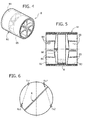
- Figures 4 and 5 are a perspective view and a cross-sectional view and at an enlarged scale of an example of turbine flowmeter according to the prior art.
- the flowmeter B comprises a cylindrical tubular body B1, made for example of plastic material, in particular transparent plastic material, defining an inlet portion B2 and an outlet portion B3 for the flow of air that traverses the flowmeter B.
- two conveying devices B4, B5 ( Figures 4 and 5 ) comprising a plurality of stationary fins, rigidly connected to the body of the filter B1 and shaped so as to impart a helical direction on the flow of air that traverses it.
- the structure of the two conveying devices B4, B5 is also used for supporting in a freely rotating way a shaft B6 carrying the blades (for example two blades at 180° or three blades at 120°) of a turbine rotor R.
- the rotor R made of plastic material and of low weight, is set in rotation by the flow of air that traverses the flowmeter, after the flow has been converted into in a helical flow by the conveying device B4 at the inlet of the flowmeter.
- the speed of rotation of the rotor R is detected by sensor means of any type, for example by means of a pair of photo-emitters Tx1, Tx2 and a pair of corresponding photo-detectors Rx1, Rx2 (see Figure 6 of the annexed drawings) provided on the body of the flowmeter and designed to detect the interruption of the light beams emitted by the photo-emitters caused by the passage of the blades of the rotor R.
- the aforesaid optical detection device is consequently able to detect the speed of rotation of the rotor R, as well as also the direction of rotation.
- the signal at output from the photo-detectors is processed by electronic processing means and thus provides a reliable and accurate indication of the flow and of the volume of air emitted by the patient.
- the object of the present invention is to overcome the drawbacks discussed above.
- the subject of the invention is a flowmeter and filter assembly, comprising:
- the flowmeter and filter assembly according to the invention enables all the drawbacks of the known art that have been above discussed above to be overcome.
- integration in the filter of the air-conveying device that is set upstream of the rotor renders imperative the production of filters that use materials and constructional techniques with good standards of quality such as to guarantee the desired performance without altering in an unforeseeable way the response of the flowmeter and without introducing undesirable fluid-dynamic losses.
- the expiratory resistance of the flowmeter and filter assembly guarantees in all cases the respect of the limits envisaged by the international recommendations (ATS/ERS).
- the filter integrates the aforesaid air-conveying device, the filter itself must be provided for being uniquely designed for the respective flowmeter (which is without conveyor of air upstream of the rotor), which rules out the possibility of using an inadequate connection between the filter and the flowmeter and thus prevents the risk of inadequate measurements and/or of contamination for the patient.
- the subject of the invention is also the filter taken in itself, preferably of a disposable type, which can be coupled on the inlet mouth of a flowmeter for spirometry, said filter comprising a body defining a passage for a flow of air and having an inlet portion and an outlet portion and a filtering means interposed within said passage, and being moreover characterized in that it incorporates an air-conveying device configured for modifying the direction of the flow of air at outlet from the filter.
- the subject of the invention is also the flowmeter taken in itself, which is designed to co-operate with the filter of the invention and consequently without an air-conveying device upstream of the rotor.
- Figure 1 of the annexed drawings which shows the use of the flowmeter by a patient, also applies to the case of the assembly according to the invention.
- the assembly comprises a flowmeter B, which can be accommodated within a grip D and is provided with an antibacterial filter C for use by the patient.
- the filter C has a hollow body C1, for example made of plastic material, substantially in the form of a circular disk, with a tubular inlet portion C2 and a tubular outlet portion C3 projecting from the opposite faces of the disk body C1 and set coaxially with respect to the latter.
- the general conformation of the antibacterial filter C can also be altogether different from the one illustrated herein purely by way of example, the only essential condition, for the purposes of the invention, being that the outlet portion C3 of the antibacterial filter incorporates an air-conveying device DC configured for modifying the direction of flow of air at outlet from the filter C.
- the conveying device DC comprises three stationary fins W rigidly connected to the body C1 of the filter.
- the fins W are set at equal angular distances apart about the axis X of the filter C and are shaped for imparting a helical direction on the flow of air at outlet from the filter, such as to set the rotor R of the flowmeter in rotation.
- the fins W extend in the direction of the axis X starting from respective axial tabs T that project from the end front edge of the tubular outlet portion C3 of the filter C.
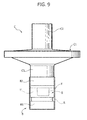
- the flowmeter B comprises, in the embodiment illustrated, a cylindrical body B1, for example made of plastic material, and in particular of transparent plastic material, having a tubular conformation.
- the body B1 has an end portion, which is fitted with slight interference on the tubular outlet portion C3 of the filter ( Figure 9 ).
- a rotor R is rotatably mounted about the axis X of the flowmeter (see Figure 9 ).
- the rotor is carried by a shaft that is mounted so that it can rotate freely within the body B1 of the flowmeter B.
- one end of the shaft of the rotor is rotatably supported by the hub of an air-conveying device B5 similar to that of the conventional flowmeter that has been described in greater detail above and is mounted within the outlet end of the flowmeter B, i.e., downstream of the rotor.
- the flowmeter B Upstream of the rotor, the flowmeter B is without any air-conveying device, the corresponding end of the shaft of the rotor being supported in rotation by a supporting body S inserted within the flowmeter B, which does not have any function of conveying the flow of air; i.e., it is not able to modify to any great extent the direction of the flow of air.
- the support S comprises three peripheral tabs T' that are inserted into the respective compartments comprised between the tabs T of the filter in the condition where the flowmeter is coupled to the filter, in which the cylindrical wall of the body B1 of the flowmeter is set on the outside of the cylindrical outlet portion C3 of the filter, and the tabs T' of the flowmeter are inserted between the tabs T projecting from the front edge of the tubular outlet portion C3 of the filter.
- the disposable filter C is made for being uniquely coupled to the flowmeter B that has been described previously.
- the only essential characteristic for the purposes of the present invention lies in the fact that the air-conveying device set upstream of the rotor of the flowmeter is integrated in the outlet portion of the filter instead of being provided in the flowmeter.
- the details of construction and the embodiments both of the filter and of the flowmeter, as well as of the parts for coupling between the flowmeter and the filter can vary widely with respect to what has been described herein purely by way of example.
- the invention opens the way to a new generation of filters, which are characterized not only in that they perform a filtering function but also in that they integrate an air-conveying device that is able to modify the direction of the flow of air at outlet from the filter in order to set the rotor of the flowmeter connected to the filter in rotation.
- Said solution renders production of filters with materials and constructional techniques of good quality compulsory also in the case of filters of a disposable type, a fact that guarantees an optimal performance and a high reliability as regards the measurements made and in terms of safety for the patient.
Abstract
Description
- The field of application of the present invention is spirometry, i.e., the evaluation of the respiratory function of a person, for instance in the clinical field (pneumology) or sports field (for example, for the evaluation of the suitability for practising sports activities) or legal field (for example, in the field of occupational medicine).
- Evaluation tests consist in measuring the flow of air exhaled/inhaled via a flowmeter connected to the mouth of the subject during particular manoeuvres indicated by a skilled operator.
- There exist different types of flowmeters. The most common ones are the so-called Fleisch pneumotachograph, Lilly pneumotachograph, Pitot pneumotachograph, mass flowmeter, turbine flowmeter, ultrasound flowmeter and variable-orifice flowmeter.
- The present invention regards in particular turbine flowmeters.
Figure 1 of the annexed drawings shows a patient wearing a nose clip A for closing the nostrils in such a way as to convey all the air exhaled into a flowmeter B provided with a grip D. Set between the flowmeter B and the mouth of the patient is an antibacterial filter C, of the disposable type, which is to prevent any contamination in the breathing-in phase.Figures 2 and 3 of the annexed drawings show in perspective view and side view, and at an enlarged scale, the antibacterial filter C according to the prior art, comprising a hollow body C1, substantially in the form of a circular disk, with an inlet portion C2 that is to receive a flow of air exhaled by the patient and an outlet portion C3 that is to convey the air that has traversed the filter C towards the flowmeter B. Interposed in the hollow disk-shaped body C1 is a disk of filtering material F (represented with a dashed line inFigure 3 ). -
Figures 4 and 5 are a perspective view and a cross-sectional view and at an enlarged scale of an example of turbine flowmeter according to the prior art. - The flowmeter B comprises a cylindrical tubular body B1, made for example of plastic material, in particular transparent plastic material, defining an inlet portion B2 and an outlet portion B3 for the flow of air that traverses the flowmeter B. Provided within the portions B2, B3 are two conveying devices B4, B5 (
Figures 4 and 5 ) comprising a plurality of stationary fins, rigidly connected to the body of the filter B1 and shaped so as to impart a helical direction on the flow of air that traverses it. The structure of the two conveying devices B4, B5 is also used for supporting in a freely rotating way a shaft B6 carrying the blades (for example two blades at 180° or three blades at 120°) of a turbine rotor R. The rotor R, made of plastic material and of low weight, is set in rotation by the flow of air that traverses the flowmeter, after the flow has been converted into in a helical flow by the conveying device B4 at the inlet of the flowmeter. - The speed of rotation of the rotor R is detected by sensor means of any type, for example by means of a pair of photo-emitters Tx1, Tx2 and a pair of corresponding photo-detectors Rx1, Rx2 (see
Figure 6 of the annexed drawings) provided on the body of the flowmeter and designed to detect the interruption of the light beams emitted by the photo-emitters caused by the passage of the blades of the rotor R. The aforesaid optical detection device is consequently able to detect the speed of rotation of the rotor R, as well as also the direction of rotation. The signal at output from the photo-detectors is processed by electronic processing means and thus provides a reliable and accurate indication of the flow and of the volume of air emitted by the patient. - Spirometry is a consolidated technique in medicine. As regards the requirements of the necessary instrumentation, international standardization guidelines are available, amongst which the following may be cited:
- ATS/ERS 2005: "STANDARDISATION OF LUNG FUNCTION TESTING" edited by V. Brusasco, R. Crapo and G. Viegi: "Standardisation of spirometry, European Respiratory Journal 2005; 26: 319-338;
- ERS/ATS 1997: "Lung volume equipment and infection control"; European Respiratory Journal 1997; 10: 1928-1932.
- One of the important requirements to be respected in apparatuses for spirometry is the protection of the airways of the patient from contact with viruses and bacteria that may be present in the instrumentation.
- Said results can be achieved with the following methods:
- 1) use of instrumentation in which all the elements in contact with the air exhaled and inhaled by the patient are disposable (disposable flowmeter);
- 2) interposition of a disposable antibacterial/antiviral filter between the flowmeter and the mouth of the patient;
- 3) disinfection of all the parts in contact with the air exhaled and inhaled by the patient.
- Of the three methods listed above, the last one is not in general considered valid on account of the excessive costs and time involved.
- As regards the first two solutions, i.e., use of a disposable flowmeter or adoption of the antibacterial filter, it is important to examine certain aspects in greater depth.
- The state of the art regarding disposable flowmeters offers different solutions already available on the market (see also the documents Nos.
WO 2005/037102 A1 ,US 5,419,326 ;US 5,997,483 ). The main difficulties that are encountered in producing an entirely disposable flowmeter are the following: - it is difficult to keep the production cost low;
- if the disposable flowmeter includes components that can alter the response of the flowmeter, it is necessary to calibrate the spirometer after each replacement of the flowmeter or to codify the flowmeter on the basis of the response given;
- no other part of the spirometer must come into contact with the air exhaled/inhaled by the subject in so far as no protective barrier constituted by an antibacterial filter is present.
- The use of a disposable antibacterial filter (for example, of the type illustrated in
Figures 1-3 of the annexed drawings) is recommended by all standardization guidelines, where it is also necessary for the following requirements to be respected: - the expiratory resistance of the ensemble flowmeter plus filter must not exceed the limit of 1.5 cm H2O/1/s, up to flows of 14 1/s so as to guarantee that the results are not altered;
- the connection between the filter and the flowmeter must be completely fluid-tight so that all the air exhaled by the patient is effectively measured;
- the efficiency of the filtering barrier against the passage of viruses and bacteria must be adequate and demonstrated with tests conducted by independent bodies.
- Further considerations should moreover be added that do not commonly appear in the technical literature in this field, but that are equally important for the reliability of the measurements and the safety of the patient.
- The response of any flowmeter can vary significantly according to the form of the antibacterial filter connected thereto (the geometry of the filter affects the characteristics of the air flow, with generation of possible turbulence).
- There are available on the market low-cost and poor-quality disposable antibacterial filters, which have reduced filtering power and do not ensure the necessary performance.
- At times it happens that an antibacterial filter is connected to a flowmeter having a diameter incompatible using adapter connectors that frequently introduce undesirable losses and increase the deadspace of the measuring system (i.e., the volume of air that the patient is forced to breathe again) in an unacceptable way and to the point of altering the fluid-dynamic characteristics for which the device is designed.
- The object of the present invention is to overcome the drawbacks discussed above.
- With a view to achieving the aforesaid purpose, the subject of the invention is a flowmeter and filter assembly, comprising:
- a flowmeter including a body defining a passage for a flow of air and having an inlet portion and an outlet portion, and a rotor, which is rotatably mounted within said flowmeter body and can be set in rotation by a flow of air that traverses the flowmeter;
- a filter, preferably a disposable one, including a body defining a passage for a flow of air and having an inlet portion and an outlet portion which can be connected to the inlet portion of the body of the flowmeter;
- an air-conveying device set upstream of the rotor of the flowmeter and configured for modifying the direction of the flow of air directed towards the rotor in such a way as to set said rotor in rotation; and
- sensor means associated to the aforesaid flowmeter, for detecting the speed of rotation of the rotor;
said flowmeter assembly being characterized in that the air-conveying device set upstream of the rotor forms part of the aforesaid filter and not of said flowmeter. - Thanks to the characteristics indicated above, the flowmeter and filter assembly according to the invention enables all the drawbacks of the known art that have been above discussed above to be overcome. In particular, integration in the filter of the air-conveying device that is set upstream of the rotor renders imperative the production of filters that use materials and constructional techniques with good standards of quality such as to guarantee the desired performance without altering in an unforeseeable way the response of the flowmeter and without introducing undesirable fluid-dynamic losses. In particular, thanks to the aforesaid characteristics, the expiratory resistance of the flowmeter and filter assembly guarantees in all cases the respect of the limits envisaged by the international recommendations (ATS/ERS). Since the filter integrates the aforesaid air-conveying device, the filter itself must be provided for being uniquely designed for the respective flowmeter (which is without conveyor of air upstream of the rotor), which rules out the possibility of using an inadequate connection between the filter and the flowmeter and thus prevents the risk of inadequate measurements and/or of contamination for the patient.
- The subject of the invention is also the filter taken in itself, preferably of a disposable type, which can be coupled on the inlet mouth of a flowmeter for spirometry, said filter comprising a body defining a passage for a flow of air and having an inlet portion and an outlet portion and a filtering means interposed within said passage, and being moreover characterized in that it incorporates an air-conveying device configured for modifying the direction of the flow of air at outlet from the filter.
- Finally, the subject of the invention is also the flowmeter taken in itself, which is designed to co-operate with the filter of the invention and consequently without an air-conveying device upstream of the rotor.
- Further characteristics and advantages of the invention will emerge from the ensuing description with reference to the annexed drawings, which are provided purely by way of non-limiting example and in which:
-
Figure 1 , already described above, shows the use of a flowmeter provided with an antibacterial filter of the turbine type; -
Figures 2 and 3 are a perspective view and a side view, respectively, of an antibacterial filter according to the prior art; -
Figure 4 and Figure 5 are, respectively, a perspective view and a cross-sectional view and at an enlarged scale of a turbine flowmeter according to the prior art; -
Figure 6 is a schematic cross-sectional view in a plane orthogonal to the axis of the filter that shows the working principle of the sensors of the speed of rotation of the rotor of the flowmeter, provided according to the prior art; -
Figures 7 and8 are exploded perspective views of a preferred embodiment of the flowmeter and filter assembly according to the present invention; -
Figure 9 is a side view of the assembly according to the invention in the assembled condition; and -
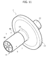
Figures 10 and11 are two further perspective views of the preferred embodiment of the flowmeter and filter assembly according to the invention. - In
Figures 7-11 , the parts in common with the ones illustrated inFigures 1-6 are designated by the same reference numbers. -
Figure 1 of the annexed drawings, which shows the use of the flowmeter by a patient, also applies to the case of the assembly according to the invention. Also in this case, the assembly comprises a flowmeter B, which can be accommodated within a grip D and is provided with an antibacterial filter C for use by the patient. - With reference to
Figures 7-11 , also in the case of the preferred embodiment of the invention that is illustrated here, the filter C has a hollow body C1, for example made of plastic material, substantially in the form of a circular disk, with a tubular inlet portion C2 and a tubular outlet portion C3 projecting from the opposite faces of the disk body C1 and set coaxially with respect to the latter. - It should be noted that the general conformation of the antibacterial filter C can also be altogether different from the one illustrated herein purely by way of example, the only essential condition, for the purposes of the invention, being that the outlet portion C3 of the antibacterial filter incorporates an air-conveying device DC configured for modifying the direction of flow of air at outlet from the filter C.
- In the case of the example illustrated, the conveying device DC comprises three stationary fins W rigidly connected to the body C1 of the filter. The fins W are set at equal angular distances apart about the axis X of the filter C and are shaped for imparting a helical direction on the flow of air at outlet from the filter, such as to set the rotor R of the flowmeter in rotation. The fins W extend in the direction of the axis X starting from respective axial tabs T that project from the end front edge of the tubular outlet portion C3 of the filter C.
- With reference once again to
Figures 7-11 , the flowmeter B according to the invention comprises, in the embodiment illustrated, a cylindrical body B1, for example made of plastic material, and in particular of transparent plastic material, having a tubular conformation. The body B1 has an end portion, which is fitted with slight interference on the tubular outlet portion C3 of the filter (Figure 9 ). Within the body B1 of the flowmeter, a rotor R is rotatably mounted about the axis X of the flowmeter (seeFigure 9 ). The rotor is carried by a shaft that is mounted so that it can rotate freely within the body B1 of the flowmeter B. For this purpose, one end of the shaft of the rotor is rotatably supported by the hub of an air-conveying device B5 similar to that of the conventional flowmeter that has been described in greater detail above and is mounted within the outlet end of the flowmeter B, i.e., downstream of the rotor. Upstream of the rotor, the flowmeter B is without any air-conveying device, the corresponding end of the shaft of the rotor being supported in rotation by a supporting body S inserted within the flowmeter B, which does not have any function of conveying the flow of air; i.e., it is not able to modify to any great extent the direction of the flow of air. The support S comprises three peripheral tabs T' that are inserted into the respective compartments comprised between the tabs T of the filter in the condition where the flowmeter is coupled to the filter, in which the cylindrical wall of the body B1 of the flowmeter is set on the outside of the cylindrical outlet portion C3 of the filter, and the tabs T' of the flowmeter are inserted between the tabs T projecting from the front edge of the tubular outlet portion C3 of the filter. - Hence, as emerges clearly from the drawings, the disposable filter C is made for being uniquely coupled to the flowmeter B that has been described previously.
- As already mentioned, the only essential characteristic for the purposes of the present invention lies in the fact that the air-conveying device set upstream of the rotor of the flowmeter is integrated in the outlet portion of the filter instead of being provided in the flowmeter. Of course, without prejudice to said essential characteristic, the details of construction and the embodiments both of the filter and of the flowmeter, as well as of the parts for coupling between the flowmeter and the filter, can vary widely with respect to what has been described herein purely by way of example.
- Furthermore, even though the invention has been devised particularly for use of a disposable filter, it is not ruled out that it may be used also for a non-disposable filter.
- As is evident from the foregoing description, the invention opens the way to a new generation of filters, which are characterized not only in that they perform a filtering function but also in that they integrate an air-conveying device that is able to modify the direction of the flow of air at outlet from the filter in order to set the rotor of the flowmeter connected to the filter in rotation. Said solution renders production of filters with materials and constructional techniques of good quality compulsory also in the case of filters of a disposable type, a fact that guarantees an optimal performance and a high reliability as regards the measurements made and in terms of safety for the patient.
Claims (9)
- A filter for spirometry, preferably a disposable one, which can be connected to a flowmeter for spirometry, said filter comprising:- a body (C1) defining a passage for a flow of air and having an inlet portion (C2) and an outlet portion (C3); and- a filtering means (F) interposed within said passage,
said filter being characterized in that it includes an air-conveying device (DC) configured for modifying the direction of the flow of air at outlet from the filter (C). - The filter according to Claim 1, characterized in that said air-conveying device (DC) comprises a plurality of stationary fins (W), rigidly connected to the body of the filter (C1) and configured for modifying the direction of the flow of air at outlet from the filter (C).
- The filter according to Claim 2, characterized in that said fins (W) are configured for imparting a helical direction on the flow of air at outlet from the filter.
- The filter according to any one of the preceding claims, characterized in that it comprises an outlet portion (C3, T) configured for coupling with a complementary portion (T') defined on the inlet portion (B2) of a flowmeter.
- A flowmeter and filter assembly for spirometry, comprising:- a flowmeter (B) including a body (B1) defining a passage for a flow of air and having an inlet portion (B2) and an outlet portion (B3), and a rotor (R), which is rotatably mounted within said flowmeter body (B1) and can be set in rotation by a flow of air that traverses the flowmeter;- a filter (C), preferably a disposable one, including a body (C1) defining a passage for a flow of air and having an inlet portion (C2) and an outlet portion (C3) which can be connected to the inlet portion (B2) of the body (B1) of the flowmeter;- an air-conveying device (DC) set upstream of the rotor (R) configured for modifying the direction of the flow of air directed towards the rotor in such a way as to set said rotor (R) in rotation; and- sensor means associated to said flowmeter, for detecting the speed of rotation of the rotor,
said flowmeter being characterized in that said air-conveying device (DC) set upstream of the rotor (R) forms part of said filter (C) and not of said flowmeter (B). - The assembly according to Claim 5, characterized in that said air-conveying device (DC) comprises a plurality of stationary fins (W), rigidly connected to the body of the filter (C1) and configured for modifying the direction of the flow of air directed towards the rotor in such a way as to set said rotor (R) in rotation.
- The assembly according to Claim 6, characterized in that said fins (W) are configured for imparting a helical direction on the flow of air at outlet from the filter (C).
- The assembly according to any one of Claims 5-7, characterized in that said filter (C) comprises an outlet portion (C3, T) shaped for coupling with a complementary portion (T') defined at the inlet portion (B2) of the flowmeter.
- A flowmeter for spirometry, including a body (B1) defining a passage for a flow of air and having an inlet portion (B2) and an outlet portion (B3), and a rotor (R), which is rotatably mounted within said flowmeter body and can be set in rotation by a flow of air that traverses the flowmeter, said flowmeter further comprising sensor means for detecting the speed of rotation of the rotor (R),
said flowmeter being characterized in that it has an inlet portion (B2) configured for coupling with the outlet portion (C3) of a filter according to Claim 1, said flowmeter being without an air-conveying device set upstream of the rotor (R) and being configured for modifying the direction of the flow of air directed to the rotor.
Priority Applications (4)
| Application Number | Priority Date | Filing Date | Title |
|---|---|---|---|
| EP11185374.3A EP2583622B1 (en) | 2011-10-17 | 2011-10-17 | Anti-bacterial filter for tests on respiratory funcionality |
| US14/351,966 US9999374B2 (en) | 2011-10-17 | 2012-10-08 | Antibacterial filter and turbine flowmeter for tests on respiratory functionality |
| CN201280049995.XA CN103987315B (en) | 2011-10-17 | 2012-10-08 | The antibacterial air filter of test and turbine flowmeter for respiratory function |
| PCT/IB2012/055427 WO2013057623A1 (en) | 2011-10-17 | 2012-10-08 | Antibacterial filter and turbine flowmeter for tests on respiratory functionality |
Applications Claiming Priority (1)
| Application Number | Priority Date | Filing Date | Title |
|---|---|---|---|
| EP11185374.3A EP2583622B1 (en) | 2011-10-17 | 2011-10-17 | Anti-bacterial filter for tests on respiratory funcionality |
Publications (2)
| Publication Number | Publication Date |
|---|---|
| EP2583622A1 true EP2583622A1 (en) | 2013-04-24 |
| EP2583622B1 EP2583622B1 (en) | 2016-03-02 |
Family
ID=47221493
Family Applications (1)
| Application Number | Title | Priority Date | Filing Date |
|---|---|---|---|
| EP11185374.3A Active EP2583622B1 (en) | 2011-10-17 | 2011-10-17 | Anti-bacterial filter for tests on respiratory funcionality |
Country Status (4)
| Country | Link |
|---|---|
| US (1) | US9999374B2 (en) |
| EP (1) | EP2583622B1 (en) |
| CN (1) | CN103987315B (en) |
| WO (1) | WO2013057623A1 (en) |
Families Citing this family (8)
| Publication number | Priority date | Publication date | Assignee | Title |
|---|---|---|---|---|
| GB2532705B (en) * | 2014-08-19 | 2016-10-05 | Wwws Uk Ltd | Spirometer |
| CN105496413B (en) * | 2015-12-15 | 2018-10-09 | 康泰医学系统(秦皇岛)股份有限公司 | A kind of spirometer lung capacity acquisition methods |
| CN107569233A (en) * | 2017-08-31 | 2018-01-12 | 中国科学院电子学研究所 | Obtain the device and method of expiration index |
| USD900319S1 (en) | 2018-08-21 | 2020-10-27 | Fisher & Paykel Healthcare Limited | Fluid trap for a respiratory device |
| KR102021096B1 (en) * | 2019-07-30 | 2019-09-11 | (주)지에이치이노텍 | apparatus for respiration rehabilitation |
| KR102054115B1 (en) * | 2019-08-09 | 2019-12-09 | 조시온 | Airway intubation assembly for check of patient breathing |
| GB2579449A (en) * | 2019-09-20 | 2020-06-24 | Husain Moiyed Tailor Shabbir | Single patient use throwaway device for recording respiratory flow rates |
| US20230191306A1 (en) * | 2021-12-22 | 2023-06-22 | Sdi Diagnostics, Inc. | Breathing tube filter and filter assembly |
Citations (6)
| Publication number | Priority date | Publication date | Assignee | Title |
|---|---|---|---|---|
| CH627359A5 (en) * | 1978-02-22 | 1982-01-15 | Schiller Alfred | Spirometer for determination of the respiratory time volume |
| FR2560988A1 (en) * | 1984-03-09 | 1985-09-13 | Travert Raymond | Volumetric counter for spirometer |
| US5419326A (en) | 1992-06-03 | 1995-05-30 | Ndd Medizintechnik Gmbh | Spirometer, more particularly an ultrasonic spirometer |
| US5997483A (en) | 1996-06-21 | 1999-12-07 | Desert Moon Development Limited Partnership | Individualized and calibrated air tube for spirometer |
| WO2005037102A1 (en) | 2003-10-22 | 2005-04-28 | Mir S.R.L. | Disposable spirometer with plastic injection moulded turbine |
| KR100930472B1 (en) * | 2009-09-15 | 2009-12-09 | 이평환 | A case of filter |
Family Cites Families (9)
| Publication number | Priority date | Publication date | Assignee | Title |
|---|---|---|---|---|
| NL8802809A (en) * | 1988-11-15 | 1990-06-01 | Mijnhardt Bv | GAS FLOW METER. |
| US5230727A (en) * | 1992-06-05 | 1993-07-27 | Cybermedic, Inc. | Air filter for medical ventilation equipment and the like |
| US5337739A (en) * | 1992-08-14 | 1994-08-16 | Polmonary Data Service Instrumentation, Inc. | Disposable bacteria filter |
| US5390668A (en) * | 1993-06-22 | 1995-02-21 | Pulmonary Data Service Instrumentation, Inc. | Disposable multitest bacteria filter |
| CN2498587Y (en) * | 2001-08-21 | 2002-07-03 | 周尔范 | Gas flowmeter |
| FR2850284B1 (en) * | 2003-01-27 | 2012-11-30 | Saime Sarl | BREATHING DEVICE AND REGULATION METHOD |
| GB0706204D0 (en) * | 2007-03-29 | 2007-05-09 | Ireland Vitalograph | Spirometers |
| CN201440079U (en) * | 2009-02-10 | 2010-04-21 | 中国人民解放军总后勤部油料研究所 | Liquid turbine flowmeter |
| WO2011143289A2 (en) * | 2010-05-11 | 2011-11-17 | Dalhousie University | Respiratory device filter |
-
2011
- 2011-10-17 EP EP11185374.3A patent/EP2583622B1/en active Active
-
2012
- 2012-10-08 US US14/351,966 patent/US9999374B2/en active Active
- 2012-10-08 WO PCT/IB2012/055427 patent/WO2013057623A1/en active Application Filing
- 2012-10-08 CN CN201280049995.XA patent/CN103987315B/en active Active
Patent Citations (6)
| Publication number | Priority date | Publication date | Assignee | Title |
|---|---|---|---|---|
| CH627359A5 (en) * | 1978-02-22 | 1982-01-15 | Schiller Alfred | Spirometer for determination of the respiratory time volume |
| FR2560988A1 (en) * | 1984-03-09 | 1985-09-13 | Travert Raymond | Volumetric counter for spirometer |
| US5419326A (en) | 1992-06-03 | 1995-05-30 | Ndd Medizintechnik Gmbh | Spirometer, more particularly an ultrasonic spirometer |
| US5997483A (en) | 1996-06-21 | 1999-12-07 | Desert Moon Development Limited Partnership | Individualized and calibrated air tube for spirometer |
| WO2005037102A1 (en) | 2003-10-22 | 2005-04-28 | Mir S.R.L. | Disposable spirometer with plastic injection moulded turbine |
| KR100930472B1 (en) * | 2009-09-15 | 2009-12-09 | 이평환 | A case of filter |
Non-Patent Citations (2)
| Title |
|---|
| "Lung volume equipment and infection control", EUROPEAN RESPIRATORY JOURNAL, vol. 10, 1997, pages 1928 - 1932 |
| "Standardisation of spirometry, European Respiratory Journal", vol. 26, 2005, article "STANDARDISATION OF LUNG FUNCTION TESTING", pages: 319 - 338 |
Also Published As
| Publication number | Publication date |
|---|---|
| US20150265185A1 (en) | 2015-09-24 |
| CN103987315A (en) | 2014-08-13 |
| WO2013057623A1 (en) | 2013-04-25 |
| EP2583622B1 (en) | 2016-03-02 |
| US9999374B2 (en) | 2018-06-19 |
| CN103987315B (en) | 2016-08-17 |
Similar Documents
| Publication | Publication Date | Title |
|---|---|---|
| EP2583622B1 (en) | Anti-bacterial filter for tests on respiratory funcionality | |
| FI84757B (en) | FOER STROEMNINGSMAETNING AVSETT GASENS STROEMNING BEGRAENSANDE OCH STYRANDE ORGAN. | |
| EP2833789B1 (en) | Spirometer | |
| US6312389B1 (en) | Multiple function airway adapter | |
| US6126613A (en) | Device and method to measure inhalation and exhalation air flows | |
| EP0815792A1 (en) | Measuring detector and system for the measurement of gas flow | |
| US4441505A (en) | Sensing device for human lung exhalation/inhalation air flow measurement | |
| US9468734B2 (en) | Gas flow system, adaptor, and method | |
| JPH10509891A (en) | Peak flow meter | |
| JP6558549B2 (en) | Mouthpiece, manufacturing method thereof, and breath test apparatus | |
| EP2579776B1 (en) | Spirometer breathing tube with compound membrane | |
| EP1689296B1 (en) | Disposable spirometer with plastic injection moulded turbine | |
| JP2000298044A (en) | Breathing flowrate and flow velocity measuring device | |
| JP5950334B2 (en) | Respiratory mask | |
| EP3949856B1 (en) | A disposable combined device with antimicrobial filter and flowmeter, for use in spirometry | |
| WO2021053380A1 (en) | Single patient use throwaway device for recording respiratory flow rates | |
| US20210153774A1 (en) | Single Patient Use Throwaway Device for Recording Respiratory Flow Rates | |
| WO2019004966A2 (en) | Ultrasonic spirometer | |
| US8585608B2 (en) | Flow meter for pulmonary function tests | |
| CN209316737U (en) | A kind of nasal oxygen tube with oxygen instruction device | |
| GB2579449A (en) | Single patient use throwaway device for recording respiratory flow rates | |
| RU2008799C1 (en) | Device for checking conduction of nasal passages | |
| RU2217050C1 (en) | Device for measuring air flow volume discharge rate | |
| CN117179740A (en) | Gas flow turbine sensor for pulmonary function instrument | |
| CN115736889A (en) | Cardiovascular disease monitor based on gas analysis |
Legal Events
| Date | Code | Title | Description |
|---|---|---|---|
| PUAI | Public reference made under article 153(3) epc to a published international application that has entered the european phase |
Free format text: ORIGINAL CODE: 0009012 |
|
| 17P | Request for examination filed |
Effective date: 20121010 |
|
| AK | Designated contracting states |
Kind code of ref document: A1 Designated state(s): AL AT BE BG CH CY CZ DE DK EE ES FI FR GB GR HR HU IE IS IT LI LT LU LV MC MK MT NL NO PL PT RO RS SE SI SK SM TR |
|
| AX | Request for extension of the european patent |
Extension state: BA ME |
|
| RAP1 | Party data changed (applicant data changed or rights of an application transferred) |
Owner name: COSMED S.R.L. |
|
| RIN1 | Information on inventor provided before grant (corrected) |
Inventor name: BRUGNOLI, PAOLO, C/O COSMED S.R.L. |
|
| GRAP | Despatch of communication of intention to grant a patent |
Free format text: ORIGINAL CODE: EPIDOSNIGR1 |
|
| INTG | Intention to grant announced |
Effective date: 20150924 |
|
| GRAS | Grant fee paid |
Free format text: ORIGINAL CODE: EPIDOSNIGR3 |
|
| GRAA | (expected) grant |
Free format text: ORIGINAL CODE: 0009210 |
|
| AK | Designated contracting states |
Kind code of ref document: B1 Designated state(s): AL AT BE BG CH CY CZ DE DK EE ES FI FR GB GR HR HU IE IS IT LI LT LU LV MC MK MT NL NO PL PT RO RS SE SI SK SM TR |
|
| REG | Reference to a national code |
Ref country code: GB Ref legal event code: FG4D |
|
| REG | Reference to a national code |
Ref country code: AT Ref legal event code: REF Ref document number: 777405 Country of ref document: AT Kind code of ref document: T Effective date: 20160315 Ref country code: CH Ref legal event code: EP |
|
| REG | Reference to a national code |
Ref country code: IE Ref legal event code: FG4D |
|
| REG | Reference to a national code |
Ref country code: DE Ref legal event code: R096 Ref document number: 602011023574 Country of ref document: DE |
|
| RAP2 | Party data changed (patent owner data changed or rights of a patent transferred) |
Owner name: COSMED S.R.L. |
|
| REG | Reference to a national code |
Ref country code: NL Ref legal event code: MP Effective date: 20160302 |
|
| REG | Reference to a national code |
Ref country code: LT Ref legal event code: MG4D |
|
| REG | Reference to a national code |
Ref country code: AT Ref legal event code: MK05 Ref document number: 777405 Country of ref document: AT Kind code of ref document: T Effective date: 20160302 |
|
| PG25 | Lapsed in a contracting state [announced via postgrant information from national office to epo] |
Ref country code: FI Free format text: LAPSE BECAUSE OF FAILURE TO SUBMIT A TRANSLATION OF THE DESCRIPTION OR TO PAY THE FEE WITHIN THE PRESCRIBED TIME-LIMIT Effective date: 20160302 Ref country code: NO Free format text: LAPSE BECAUSE OF FAILURE TO SUBMIT A TRANSLATION OF THE DESCRIPTION OR TO PAY THE FEE WITHIN THE PRESCRIBED TIME-LIMIT Effective date: 20160602 Ref country code: GR Free format text: LAPSE BECAUSE OF FAILURE TO SUBMIT A TRANSLATION OF THE DESCRIPTION OR TO PAY THE FEE WITHIN THE PRESCRIBED TIME-LIMIT Effective date: 20160603 Ref country code: ES Free format text: LAPSE BECAUSE OF FAILURE TO SUBMIT A TRANSLATION OF THE DESCRIPTION OR TO PAY THE FEE WITHIN THE PRESCRIBED TIME-LIMIT Effective date: 20160302 Ref country code: HR Free format text: LAPSE BECAUSE OF FAILURE TO SUBMIT A TRANSLATION OF THE DESCRIPTION OR TO PAY THE FEE WITHIN THE PRESCRIBED TIME-LIMIT Effective date: 20160302 |
|
| PG25 | Lapsed in a contracting state [announced via postgrant information from national office to epo] |
Ref country code: RS Free format text: LAPSE BECAUSE OF FAILURE TO SUBMIT A TRANSLATION OF THE DESCRIPTION OR TO PAY THE FEE WITHIN THE PRESCRIBED TIME-LIMIT Effective date: 20160302 Ref country code: AT Free format text: LAPSE BECAUSE OF FAILURE TO SUBMIT A TRANSLATION OF THE DESCRIPTION OR TO PAY THE FEE WITHIN THE PRESCRIBED TIME-LIMIT Effective date: 20160302 Ref country code: LV Free format text: LAPSE BECAUSE OF FAILURE TO SUBMIT A TRANSLATION OF THE DESCRIPTION OR TO PAY THE FEE WITHIN THE PRESCRIBED TIME-LIMIT Effective date: 20160302 Ref country code: SE Free format text: LAPSE BECAUSE OF FAILURE TO SUBMIT A TRANSLATION OF THE DESCRIPTION OR TO PAY THE FEE WITHIN THE PRESCRIBED TIME-LIMIT Effective date: 20160302 Ref country code: PL Free format text: LAPSE BECAUSE OF FAILURE TO SUBMIT A TRANSLATION OF THE DESCRIPTION OR TO PAY THE FEE WITHIN THE PRESCRIBED TIME-LIMIT Effective date: 20160302 Ref country code: LT Free format text: LAPSE BECAUSE OF FAILURE TO SUBMIT A TRANSLATION OF THE DESCRIPTION OR TO PAY THE FEE WITHIN THE PRESCRIBED TIME-LIMIT Effective date: 20160302 Ref country code: NL Free format text: LAPSE BECAUSE OF FAILURE TO SUBMIT A TRANSLATION OF THE DESCRIPTION OR TO PAY THE FEE WITHIN THE PRESCRIBED TIME-LIMIT Effective date: 20160302 |
|
| PG25 | Lapsed in a contracting state [announced via postgrant information from national office to epo] |
Ref country code: IS Free format text: LAPSE BECAUSE OF FAILURE TO SUBMIT A TRANSLATION OF THE DESCRIPTION OR TO PAY THE FEE WITHIN THE PRESCRIBED TIME-LIMIT Effective date: 20160702 Ref country code: EE Free format text: LAPSE BECAUSE OF FAILURE TO SUBMIT A TRANSLATION OF THE DESCRIPTION OR TO PAY THE FEE WITHIN THE PRESCRIBED TIME-LIMIT Effective date: 20160302 |
|
| PG25 | Lapsed in a contracting state [announced via postgrant information from national office to epo] |
Ref country code: PT Free format text: LAPSE BECAUSE OF FAILURE TO SUBMIT A TRANSLATION OF THE DESCRIPTION OR TO PAY THE FEE WITHIN THE PRESCRIBED TIME-LIMIT Effective date: 20160704 Ref country code: CZ Free format text: LAPSE BECAUSE OF FAILURE TO SUBMIT A TRANSLATION OF THE DESCRIPTION OR TO PAY THE FEE WITHIN THE PRESCRIBED TIME-LIMIT Effective date: 20160302 Ref country code: SM Free format text: LAPSE BECAUSE OF FAILURE TO SUBMIT A TRANSLATION OF THE DESCRIPTION OR TO PAY THE FEE WITHIN THE PRESCRIBED TIME-LIMIT Effective date: 20160302 Ref country code: RO Free format text: LAPSE BECAUSE OF FAILURE TO SUBMIT A TRANSLATION OF THE DESCRIPTION OR TO PAY THE FEE WITHIN THE PRESCRIBED TIME-LIMIT Effective date: 20160302 Ref country code: SK Free format text: LAPSE BECAUSE OF FAILURE TO SUBMIT A TRANSLATION OF THE DESCRIPTION OR TO PAY THE FEE WITHIN THE PRESCRIBED TIME-LIMIT Effective date: 20160302 |
|
| REG | Reference to a national code |
Ref country code: DE Ref legal event code: R097 Ref document number: 602011023574 Country of ref document: DE |
|
| PG25 | Lapsed in a contracting state [announced via postgrant information from national office to epo] |
Ref country code: BE Free format text: LAPSE BECAUSE OF FAILURE TO SUBMIT A TRANSLATION OF THE DESCRIPTION OR TO PAY THE FEE WITHIN THE PRESCRIBED TIME-LIMIT Effective date: 20160302 |
|
| PLBE | No opposition filed within time limit |
Free format text: ORIGINAL CODE: 0009261 |
|
| STAA | Information on the status of an ep patent application or granted ep patent |
Free format text: STATUS: NO OPPOSITION FILED WITHIN TIME LIMIT |
|
| PG25 | Lapsed in a contracting state [announced via postgrant information from national office to epo] |
Ref country code: DK Free format text: LAPSE BECAUSE OF FAILURE TO SUBMIT A TRANSLATION OF THE DESCRIPTION OR TO PAY THE FEE WITHIN THE PRESCRIBED TIME-LIMIT Effective date: 20160302 |
|
| 26N | No opposition filed |
Effective date: 20161205 |
|
| PG25 | Lapsed in a contracting state [announced via postgrant information from national office to epo] |
Ref country code: SI Free format text: LAPSE BECAUSE OF FAILURE TO SUBMIT A TRANSLATION OF THE DESCRIPTION OR TO PAY THE FEE WITHIN THE PRESCRIBED TIME-LIMIT Effective date: 20160302 Ref country code: BG Free format text: LAPSE BECAUSE OF FAILURE TO SUBMIT A TRANSLATION OF THE DESCRIPTION OR TO PAY THE FEE WITHIN THE PRESCRIBED TIME-LIMIT Effective date: 20160602 |
|
| REG | Reference to a national code |
Ref country code: DE Ref legal event code: R119 Ref document number: 602011023574 Country of ref document: DE |
|
| REG | Reference to a national code |
Ref country code: CH Ref legal event code: PL |
|
| REG | Reference to a national code |
Ref country code: IE Ref legal event code: MM4A |
|
| REG | Reference to a national code |
Ref country code: FR Ref legal event code: ST Effective date: 20170630 |
|
| PG25 | Lapsed in a contracting state [announced via postgrant information from national office to epo] |
Ref country code: DE Free format text: LAPSE BECAUSE OF NON-PAYMENT OF DUE FEES Effective date: 20170503 Ref country code: CH Free format text: LAPSE BECAUSE OF NON-PAYMENT OF DUE FEES Effective date: 20161031 Ref country code: LI Free format text: LAPSE BECAUSE OF NON-PAYMENT OF DUE FEES Effective date: 20161031 Ref country code: FR Free format text: LAPSE BECAUSE OF NON-PAYMENT OF DUE FEES Effective date: 20161102 |
|
| PG25 | Lapsed in a contracting state [announced via postgrant information from national office to epo] |
Ref country code: LU Free format text: LAPSE BECAUSE OF NON-PAYMENT OF DUE FEES Effective date: 20161017 |
|
| PG25 | Lapsed in a contracting state [announced via postgrant information from national office to epo] |
Ref country code: IE Free format text: LAPSE BECAUSE OF NON-PAYMENT OF DUE FEES Effective date: 20161017 |
|
| PG25 | Lapsed in a contracting state [announced via postgrant information from national office to epo] |
Ref country code: HU Free format text: LAPSE BECAUSE OF FAILURE TO SUBMIT A TRANSLATION OF THE DESCRIPTION OR TO PAY THE FEE WITHIN THE PRESCRIBED TIME-LIMIT; INVALID AB INITIO Effective date: 20111017 Ref country code: CY Free format text: LAPSE BECAUSE OF FAILURE TO SUBMIT A TRANSLATION OF THE DESCRIPTION OR TO PAY THE FEE WITHIN THE PRESCRIBED TIME-LIMIT Effective date: 20160302 |
|
| PG25 | Lapsed in a contracting state [announced via postgrant information from national office to epo] |
Ref country code: MK Free format text: LAPSE BECAUSE OF FAILURE TO SUBMIT A TRANSLATION OF THE DESCRIPTION OR TO PAY THE FEE WITHIN THE PRESCRIBED TIME-LIMIT Effective date: 20160302 Ref country code: MT Free format text: LAPSE BECAUSE OF NON-PAYMENT OF DUE FEES Effective date: 20161031 Ref country code: MC Free format text: LAPSE BECAUSE OF FAILURE TO SUBMIT A TRANSLATION OF THE DESCRIPTION OR TO PAY THE FEE WITHIN THE PRESCRIBED TIME-LIMIT Effective date: 20160302 Ref country code: TR Free format text: LAPSE BECAUSE OF FAILURE TO SUBMIT A TRANSLATION OF THE DESCRIPTION OR TO PAY THE FEE WITHIN THE PRESCRIBED TIME-LIMIT Effective date: 20160302 |
|
| PG25 | Lapsed in a contracting state [announced via postgrant information from national office to epo] |
Ref country code: AL Free format text: LAPSE BECAUSE OF FAILURE TO SUBMIT A TRANSLATION OF THE DESCRIPTION OR TO PAY THE FEE WITHIN THE PRESCRIBED TIME-LIMIT Effective date: 20160302 |
|
| P01 | Opt-out of the competence of the unified patent court (upc) registered |
Effective date: 20230524 |
|
| PGFP | Annual fee paid to national office [announced via postgrant information from national office to epo] |
Ref country code: GB Payment date: 20231024 Year of fee payment: 13 |
|
| PGFP | Annual fee paid to national office [announced via postgrant information from national office to epo] |
Ref country code: IT Payment date: 20231009 Year of fee payment: 13 |