EP2604935A1 - Heating, ventilation and air conditioning system user interface having proportional animation graphics and method of operation thereof - Google Patents
Heating, ventilation and air conditioning system user interface having proportional animation graphics and method of operation thereof Download PDFInfo
- Publication number
- EP2604935A1 EP2604935A1 EP12197009.9A EP12197009A EP2604935A1 EP 2604935 A1 EP2604935 A1 EP 2604935A1 EP 12197009 A EP12197009 A EP 12197009A EP 2604935 A1 EP2604935 A1 EP 2604935A1
- Authority
- EP
- European Patent Office
- Prior art keywords
- display
- user interface
- animation graphics
- hvac system
- proportional
- Prior art date
- Legal status (The legal status is an assumption and is not a legal conclusion. Google has not performed a legal analysis and makes no representation as to the accuracy of the status listed.)
- Withdrawn
Links
Images


Classifications
-
- F—MECHANICAL ENGINEERING; LIGHTING; HEATING; WEAPONS; BLASTING
- F24—HEATING; RANGES; VENTILATING
- F24F—AIR-CONDITIONING; AIR-HUMIDIFICATION; VENTILATION; USE OF AIR CURRENTS FOR SCREENING
- F24F11/00—Control or safety arrangements
- F24F11/30—Control or safety arrangements for purposes related to the operation of the system, e.g. for safety or monitoring
-
- F—MECHANICAL ENGINEERING; LIGHTING; HEATING; WEAPONS; BLASTING
- F24—HEATING; RANGES; VENTILATING
- F24F—AIR-CONDITIONING; AIR-HUMIDIFICATION; VENTILATION; USE OF AIR CURRENTS FOR SCREENING
- F24F11/00—Control or safety arrangements
- F24F11/50—Control or safety arrangements characterised by user interfaces or communication
- F24F11/52—Indication arrangements, e.g. displays
Definitions
- HVAC heating, ventilation and air conditioning
- thermostats Users interact with HVAC systems through user interfaces.
- the most common user interface employed today is the thermostat.
- the most basic thermostats feature one or more dials, switches or levers and allow users to set temperatures.
- More elaborate thermostats feature a liquid crystal display (LCD) screen, perhaps even of the touchscreen variety, and allow users to program their HVAC systems for automatic temperature settings, configure and maintain their HVAC systems and records of historical operation data, allowing the users to gauge the performance and efficiency of their HVAC systems.
- LCD liquid crystal display
- Thermostats necessarily include both temperature sensors and control circuitry within their housings. Some user interfaces do not qualify as thermostats, because while they communicate with temperature sensors and control circuitry, they do not include both within their housings.
- the user interface includes: (1) a display configured to provide information to a user and (2) a processor and memory coupled to the display and configured to drive the display, the display further configured to display proportional animation graphics corresponding to attributes of the HVAC system.
- Another aspect provides a method of providing service reminders on a single screen of a user interface of an HVAC system.
- the method includes: (1) providing information to a user with a display, (2) accepting input from the user and (3) displaying proportional animation graphics corresponding to attributes of the HVAC system.
- the HVAC system includes: (1) a heat pump or a compressor having at least one stage, (2) at least one condenser coil, (3) an expansion valve, (4) at least one evaporator coil, (5) a loop of pipe interconnecting the heat pump or compressor, the at least one condenser coil, the expansion valve and the at least one evaporator coil and containing a refrigerant, (6) at least one fan configured to cause outdoor air and indoor air to blow over the at least one condenser coil and the least one evaporator coil and (7) a user interface, including: (7a) a display configured to provide information to a user, (7b) a touchpad configured to accept input from the user and (7c) a processor and memory coupled to the display and the touchpad and configured to drive the display, the display further configured to display proportional animation graphics corresponding to attributes of the HVAC system.
- FIG. 1 is a block diagram of one embodiment of a user interface 100.
- the interface has a display 110 and a touchpad 120.
- the display 110 is configured to provide information to a user
- the touchpad 120 is configured to accept input from a user.
- a processor and memory 130 are coupled to the display 110 and the touchpad 120 to drive the display 110 and process the input from the touchpad 120. More accurately, software or firmware is loaded into and stored in the memory and, when executed in the processor, configures the processor to drive the display 110 and process the input from the touchpad 120.
- An HVAC system interface 140 is coupled to the processor and memory 130 and is configured to provide communication between the processor and memory 130 and the remainder of an HVAC system 150.
- the HVAC system 150 includes one or more loops of pipe (one being shown and referenced as 151) containing a refrigerant.
- Each loop transports the refrigerant among a heat pump or a compressor 152 having at least one stage, at least one condenser coil 153, an expansion valve 154 and at least one evaporator coil 155.
- One or more fans (“blowers") 156 cause outdoor air and indoor air to blow over the at least one condenser coil 153 and the at least one evaporator coil 155 to transfer heat to or from them.
- FIG. 2 is a front-side elevational view of one embodiment of the user interface of FIG 1 .
- the user interface 100 has a bezel 210.
- the display 110 is configured to display at least one screen 220 of information for the benefit of a user (the term also including an installer or any other person interested in gaining information from the user interface 100).
- the screen 220 shown in FIG. 2 includes a current temperature display portion, a setpoint temperature display portion, buttons to raise or lower the setpoint temperature, a system mode message display portion (i.e., "system is heating”) and a program status message display portion (i.e., "program is on”).
- the screen 220 also has current date and time display portions and allows the user to display other screens (via a "press for more" message).
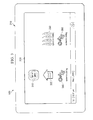
- FIG. 3 is a representation of one embodiment of a screen of the user interface of FIG. 2 having one embodiment of proportional animation graphics.
- Proportional animation graphics are one or more images (graphics) that either or both of: (1) move (are animated) or (2) contain some graphical element that varies in terms of size, number or both size and number to indicate a magnitude of an attribute that the graphics represents (i.e., are proportional to the attribute).
- Proportional animation graphics provides a relatively accurate and intuitive representation of the equipment operation to a user.
- the proportional animation graphics are located in various areas of the screen or the entirety of the background of the screen. Those skilled in the pertinent art will understand that the scope of the invention imposes no limits on the size, number or location of proportional animation graphics.
- furnace or air handler blower CFM variable airflow
- auxiliary/emergency heat on/off
- heating stage modulating or stage information
- cooling compressor
- FIG. 3 illustrates some examples.
- a blower fan may be off (represented by a proportional animation graphic 310).
- the HVAC system may be in an auxiliary or emergency heating mode (represented by a proportional animation graphic 320).
- the HVAC system may be in a normal heating mode (represented by a proportional animation graphic 330), the number of flames representing the number of heating stages that are currently active.
- the HVAC system may be in a normal cooling mode (represented by a proportional animation graphics 340, 350), the number of snowflakes representing the number of cooling stages that are currently active. Note that the graphic 340 has fewer snowflakes than the graphic 350.
- FIG. 4 is a flow diagram of one embodiment of a method of providing proportional animation graphics on a user interface of an HVAC system.
- the method begins in a start step 410.
- a step 420 information is provided to a user with a display.
- a step 430 input from the user is accepted with a touchpad.
- the display is caused to display proportional animation graphics corresponding to attributes of the HVAC system.
- the method ends in an end step 450.
Abstract
Description
- This application claims the benefit of
U.S. Provisional Application Serial No. 61/569,859, filed by Bias, et al., on December 13, 2011 - This application is directed, in general, to a heating, ventilation and air conditioning (HVAC) systems and, more specifically, to an HVAC system having a user interface, such as a thermostat.
- Users interact with HVAC systems through user interfaces. The most common user interface employed today is the thermostat. The most basic thermostats feature one or more dials, switches or levers and allow users to set temperatures. More elaborate thermostats feature a liquid crystal display (LCD) screen, perhaps even of the touchscreen variety, and allow users to program their HVAC systems for automatic temperature settings, configure and maintain their HVAC systems and records of historical operation data, allowing the users to gauge the performance and efficiency of their HVAC systems.
- Thermostats necessarily include both temperature sensors and control circuitry within their housings. Some user interfaces do not qualify as thermostats, because while they communicate with temperature sensors and control circuitry, they do not include both within their housings.
- One aspect provides a user interface. In one embodiment, the user interface includes: (1) a display configured to provide information to a user and (2) a processor and memory coupled to the display and configured to drive the display, the display further configured to display proportional animation graphics corresponding to attributes of the HVAC system.
- Another aspect provides a method of providing service reminders on a single screen of a user interface of an HVAC system. In one embodiment, the method includes: (1) providing information to a user with a display, (2) accepting input from the user and (3) displaying proportional animation graphics corresponding to attributes of the HVAC system.
- Yet another aspect provides an HVAC system. In one embodiment, the HVAC system includes: (1) a heat pump or a compressor having at least one stage, (2) at least one condenser coil, (3) an expansion valve, (4) at least one evaporator coil, (5) a loop of pipe interconnecting the heat pump or compressor, the at least one condenser coil, the expansion valve and the at least one evaporator coil and containing a refrigerant, (6) at least one fan configured to cause outdoor air and indoor air to blow over the at least one condenser coil and the least one evaporator coil and (7) a user interface, including: (7a) a display configured to provide information to a user, (7b) a touchpad configured to accept input from the user and (7c) a processor and memory coupled to the display and the touchpad and configured to drive the display, the display further configured to display proportional animation graphics corresponding to attributes of the HVAC system.
- Reference is now made to the following descriptions taken in conjunction with the accompanying drawings, in which:
-
FIG. 1 is a block diagram of one embodiment of a user interface; -
FIG. 2 is a front-side elevational view of one embodiment of a user interface; -
FIG. 3 is a representation of one embodiment of a screen of the user interface ofFIG. 2 having one embodiment of proportional animation graphics; and -
FIG. 4 is a flow diagram of one embodiment of a method of providing proportional animation graphics on a user interface of an HVAC system. -
FIG. 1 is a block diagram of one embodiment of auser interface 100. The interface has adisplay 110 and atouchpad 120. Thedisplay 110 is configured to provide information to a user, and thetouchpad 120 is configured to accept input from a user. A processor andmemory 130 are coupled to thedisplay 110 and thetouchpad 120 to drive thedisplay 110 and process the input from thetouchpad 120. More accurately, software or firmware is loaded into and stored in the memory and, when executed in the processor, configures the processor to drive thedisplay 110 and process the input from thetouchpad 120. AnHVAC system interface 140 is coupled to the processor andmemory 130 and is configured to provide communication between the processor andmemory 130 and the remainder of anHVAC system 150. In various embodiments, theHVAC system 150 includes one or more loops of pipe (one being shown and referenced as 151) containing a refrigerant. Each loop transports the refrigerant among a heat pump or acompressor 152 having at least one stage, at least onecondenser coil 153, anexpansion valve 154 and at least oneevaporator coil 155. One or more fans ("blowers") 156 cause outdoor air and indoor air to blow over the at least onecondenser coil 153 and the at least oneevaporator coil 155 to transfer heat to or from them. Those skilled in the pertinent art are familiar with conventional HVAC systems and generally understand the many embodiments and forms they may take. -
FIG. 2 is a front-side elevational view of one embodiment of the user interface ofFIG 1 . Theuser interface 100 has abezel 210. Thedisplay 110 is configured to display at least onescreen 220 of information for the benefit of a user (the term also including an installer or any other person interested in gaining information from the user interface 100). - Although unreferenced, the
screen 220 shown inFIG. 2 includes a current temperature display portion, a setpoint temperature display portion, buttons to raise or lower the setpoint temperature, a system mode message display portion (i.e., "system is heating") and a program status message display portion (i.e., "program is on"). Thescreen 220 also has current date and time display portions and allows the user to display other screens (via a "press for more" message). -
FIG. 3 is a representation of one embodiment of a screen of the user interface ofFIG. 2 having one embodiment of proportional animation graphics. Proportional animation graphics are one or more images (graphics) that either or both of: (1) move (are animated) or (2) contain some graphical element that varies in terms of size, number or both size and number to indicate a magnitude of an attribute that the graphics represents (i.e., are proportional to the attribute). Proportional animation graphics provides a relatively accurate and intuitive representation of the equipment operation to a user. In various embodiments, the proportional animation graphics are located in various areas of the screen or the entirety of the background of the screen. Those skilled in the pertinent art will understand that the scope of the invention imposes no limits on the size, number or location of proportional animation graphics. - As newer HVAC systems allow for higher granularity in operation control, users are typically uninformed with regard to details of equipment operation. For instance, current user interfaces do not provide a way to track of understand: furnace or air handler blower CFM (variable airflow); auxiliary/emergency heat (on/off); heating stage (modulating or stage information); or cooling (compressor) capacity.
- An easy to read graphical and proportional representation of some of these parameters individually or as a group would be very valuable for users:
- a. They would facilitate understanding of equipment parameters.
- b. They would provide a visible way to know the "higher end" or "advanced" features that were promised during equipment sale and installation are functioning (and to what "level").
- c. They would provide users with additional information about equipment loading or capacity which can be used as collateral information to take action on HVAC parameters to impact energy usage.
- Examples of proportional animation graphics are as follows:
- Fan. A fan graphic would depict whether the air handler or furnace is running or not. Fan blades on the fan graphic would spin faster depending on the amount of air flow (expressed in cubic feet per minute, or CFM) that the blower is delivering at a particular point in time. The CFM depends on blower RPM, torque and static pressure in the supply ducts. The apparent fan RPM is a function of the percentage of CFM being delivered. 100% (and maximum fan rate, expressed in revolutions per minute, or RPM) would be the maximum CFM allowed for the particular application. The maximum fan RPM could be adjusted for ideal viewing.
- Cooling/Heating. Cooling and heating graphic elements would both show an animation based on equipment operation. The animation would proportionally reflect the amount of heating or cooling that is being currently applied to the space. Heating stage or percentage of demand for heating and stage or percentage of compressor cooling capacity for cooling. For heating, the number of flames could increase or decrease. For cooling, the number of snowflakes could increase or decrease.
-
FIG. 3 illustrates some examples. For example, a blower fan may be off (represented by a proportional animation graphic 310). The HVAC system may be in an auxiliary or emergency heating mode (represented by a proportional animation graphic 320). The HVAC system may be in a normal heating mode (represented by a proportional animation graphic 330), the number of flames representing the number of heating stages that are currently active. The HVAC system may be in a normal cooling mode (represented by aproportional animation graphics 340, 350), the number of snowflakes representing the number of cooling stages that are currently active. Note that the graphic 340 has fewer snowflakes than the graphic 350. -
FIG. 4 is a flow diagram of one embodiment of a method of providing proportional animation graphics on a user interface of an HVAC system. The method begins in astart step 410. In astep 420, information is provided to a user with a display. In astep 430, input from the user is accepted with a touchpad. In astep 440, the display is caused to display proportional animation graphics corresponding to attributes of the HVAC system. The method ends in anend step 450. - Those skilled in the art to which this application relates will appreciate that other and further additions, deletions, substitutions and modifications may be made to the described embodiments.
Claims (10)
- A user interface for use with an HVAC system, comprising:a display configured to provide information to a user; anda processor and memory coupled to said display and configured to drive said display, said display further configured to display proportional animation graphics corresponding to attributes of said HVAC system.
- The user interface as recited in Claim 1 wherein said proportional animation graphics move to indicate a magnitude of an attribute that said proportional animation graphics represents.
- The user interface as recited in Claim 1 wherein said proportional animation graphics contain a graphical element that varies to indicate a magnitude of an attribute that said proportional animation graphics represents.
- The user interface as recited in Claim 3 wherein said graphical element varies in terms of size.
- The user interface as recited in Claim 3 wherein said graphical element varies in terms of number.
- The user interface as recited in Claim 1 wherein said proportional animation graphics include a fan graphic element having fan blades that spin based on a rate of air flow a blower is delivering at a particular point in time.
- The user interface as recited in Claim 1 wherein said proportional animation graphics include a heating graphic element having a number of flames that varies based on a percentage of heating demand.
- The user interface as recited in Claim 1 wherein said proportional animation graphics include a cooling graphic element having a number of snowflakes that varies based on a percentage of compressor cooling capacity.
- A method of providing proportional animation graphics on a user interface of an HVAC system, comprising:providing information to a user with a display;accepting input from said user; anddisplaying proportional animation graphics corresponding to attributes of said HVAC system.
- An HVAC system, comprising:a heat pump or a compressor having at least one stage;at least one condenser coil;an expansion valve;at least one evaporator coil;a loop of pipe interconnecting said heat pump or compressor, said at least one condenser coil, said expansion valve and said at least one evaporator coil and containing a refrigerant;at least one fan configured to cause outdoor air and indoor air to blow over said at least one condenser coil and said least one evaporator coil; anda user interface, including:a display configured to provide information to a user,a touchpad configured to accept input from said user, anda processor and memory coupled to said display and said touchpad and configured to drive said display, said display further configured to display proportional animation graphics corresponding to attributes of said HVAC system.
Applications Claiming Priority (2)
| Application Number | Priority Date | Filing Date | Title |
|---|---|---|---|
| US201161569859P | 2011-12-13 | 2011-12-13 | |
| US13/432,826 US20130147812A1 (en) | 2011-12-13 | 2012-03-28 | Heating, ventilation and air conditioning system user interface having proportional animation graphics and method of operation thereof |
Publications (1)
| Publication Number | Publication Date |
|---|---|
| EP2604935A1 true EP2604935A1 (en) | 2013-06-19 |
Family
ID=47519855
Family Applications (1)
| Application Number | Title | Priority Date | Filing Date |
|---|---|---|---|
| EP12197009.9A Withdrawn EP2604935A1 (en) | 2011-12-13 | 2012-12-13 | Heating, ventilation and air conditioning system user interface having proportional animation graphics and method of operation thereof |
Country Status (3)
| Country | Link |
|---|---|
| US (1) | US20130147812A1 (en) |
| EP (1) | EP2604935A1 (en) |
| CA (1) | CA2798177A1 (en) |
Families Citing this family (6)
| Publication number | Priority date | Publication date | Assignee | Title |
|---|---|---|---|---|
| US20140324227A1 (en) | 2013-04-30 | 2014-10-30 | Honeywell International Inc. | Hvac controller having a fixed segment display with an interactive message center |
| US20150074569A1 (en) * | 2013-09-12 | 2015-03-12 | Kabushiki Kaisha Toshiba | Display Device, Display Method and Display System |
| US9587848B2 (en) | 2013-12-11 | 2017-03-07 | Honeywell International Inc. | Building automation controller with rear projecting light |
| FI20145807A (en) * | 2014-09-16 | 2016-03-17 | Bitzer Kuehlmaschinenbau Gmbh | Control unit for transport unit refrigerator |
| USD781306S1 (en) | 2015-01-27 | 2017-03-14 | Johnson Controls Technology Company | Display screen or portion thereof with graphical user interface |
| US20180031266A1 (en) | 2016-07-27 | 2018-02-01 | Johnson Controls Technology Company | Interactive outdoor display |
Citations (5)
| Publication number | Priority date | Publication date | Assignee | Title |
|---|---|---|---|---|
| US5086385A (en) * | 1989-01-31 | 1992-02-04 | Custom Command Systems | Expandable home automation system |
| EP1589295A2 (en) * | 2004-04-20 | 2005-10-26 | Lg Electronics Inc. | Air conditioner |
| US20070029397A1 (en) * | 2005-08-04 | 2007-02-08 | Mueller Carl J | Thermostat with touch screen feature |
| EP1878980A2 (en) * | 2006-07-13 | 2008-01-16 | Lg Electronics Inc. | Air conditioner having image display function |
| EP2045541A1 (en) * | 2007-10-02 | 2009-04-08 | LG Electronics Inc. | Control device for air conditioner |
Family Cites Families (33)
| Publication number | Priority date | Publication date | Assignee | Title |
|---|---|---|---|---|
| US4316256A (en) * | 1979-12-31 | 1982-02-16 | Microcomm Corporation | Thermostat with automatic heat/air conditioning changeover |
| US5189412A (en) * | 1990-05-11 | 1993-02-23 | Hunter Fan Company | Remote control for a ceiling fan |
| US6513723B1 (en) * | 2000-09-28 | 2003-02-04 | Emerson Electric Co. | Method and apparatus for automatically transmitting temperature information to a thermostat |
| US6824069B2 (en) * | 2002-01-30 | 2004-11-30 | Howard B. Rosen | Programmable thermostat system employing a touch screen unit for intuitive interactive interface with a user |
| US7050026B1 (en) * | 2003-05-15 | 2006-05-23 | Howard Rosen | Reverse images in a dot matrix LCD for an environmental control device |
| US7156318B1 (en) * | 2003-09-03 | 2007-01-02 | Howard Rosen | Programmable thermostat incorporating a liquid crystal display selectively presenting adaptable system menus including changeable interactive virtual buttons |
| US7114554B2 (en) * | 2003-12-01 | 2006-10-03 | Honeywell International Inc. | Controller interface with multiple day programming |
| US10705549B2 (en) * | 2003-12-02 | 2020-07-07 | Ademco Inc. | Controller interface with menu schedule override |
| US7222494B2 (en) * | 2004-01-07 | 2007-05-29 | Honeywell International Inc. | Adaptive intelligent circulation control methods and systems |
| US20050208443A1 (en) * | 2004-03-17 | 2005-09-22 | Bachinski Thomas J | Heating appliance control system |
| US20070045444A1 (en) * | 2005-08-31 | 2007-03-01 | Ranco Incorporated Of Delaware | Thermostat including set point number line |
| US7455240B2 (en) * | 2005-08-31 | 2008-11-25 | Ranco Incorporated Of Delaware | Thermostat display system providing animated icons |
| US7702421B2 (en) * | 2007-08-27 | 2010-04-20 | Honeywell International Inc. | Remote HVAC control with building floor plan tool |
| US8091796B2 (en) * | 2007-11-30 | 2012-01-10 | Honeywell International Inc. | HVAC controller that selectively replaces operating information on a display with system status information |
| US9151510B2 (en) * | 2007-11-30 | 2015-10-06 | Honeywell International Inc. | Display for HVAC systems in remote control units |
| US20100044449A1 (en) * | 2008-08-19 | 2010-02-25 | Honeywell International Inc. | Service reminders for building control systems |
| US8332075B2 (en) * | 2008-09-15 | 2012-12-11 | Johnson Controls Technology Company | Transition temperature adjustment user interfaces |
| US8078326B2 (en) * | 2008-09-19 | 2011-12-13 | Johnson Controls Technology Company | HVAC system controller configuration |
| US8527096B2 (en) * | 2008-10-24 | 2013-09-03 | Lennox Industries Inc. | Programmable controller and a user interface for same |
| US8442693B2 (en) * | 2008-10-27 | 2013-05-14 | Lennox Industries, Inc. | System and method of use for a user interface dashboard of a heating, ventilation and air conditioning network |
| US8452456B2 (en) * | 2008-10-27 | 2013-05-28 | Lennox Industries Inc. | System and method of use for a user interface dashboard of a heating, ventilation and air conditioning network |
| US8463442B2 (en) * | 2008-10-27 | 2013-06-11 | Lennox Industries, Inc. | Alarm and diagnostics system and method for a distributed architecture heating, ventilation and air conditioning network |
| DE112010000804T5 (en) * | 2009-01-20 | 2012-08-30 | Pvt Solar, Inc. | Method and device for monitoring the operation of a solar thermal system |
| US8498753B2 (en) * | 2009-05-08 | 2013-07-30 | Ecofactor, Inc. | System, method and apparatus for just-in-time conditioning using a thermostat |
| US8528831B2 (en) * | 2009-12-07 | 2013-09-10 | Hunter Fan Company | Thermostat with efficiency display |
| US8326466B2 (en) * | 2010-01-22 | 2012-12-04 | Honeywell International Inc. | HVAC control with utility time of day pricing support |
| US8406477B2 (en) * | 2010-08-12 | 2013-03-26 | Honeywell International Inc. | System and method for constructing a three dimensional operational graphic from a two dimensional building control subsystem drawing |
| AU2011296098B2 (en) * | 2010-08-30 | 2016-07-07 | Watkins Manufacturing Corporation | Internet based spa networking system having wireless spa nodes |
| US8493008B2 (en) * | 2011-01-18 | 2013-07-23 | Dynamotors, Inc. | HVAC adjustment module |
| US8538588B2 (en) * | 2011-02-28 | 2013-09-17 | Honeywell International Inc. | Method and apparatus for configuring scheduling on a wall module |
| US10119718B2 (en) * | 2011-06-20 | 2018-11-06 | Honeywell International Inc. | Methods and systems for monitoring an air filter of an HVAC system |
| US9080784B2 (en) * | 2011-06-20 | 2015-07-14 | Honeywell International Inc. | HVAC controller with component change notification |
| US20130151017A1 (en) * | 2011-12-13 | 2013-06-13 | Larry S. Bias | Heating, ventilation and air conditioning system user interface having separate programming and manual mode screens and method of operation thereof |
-
2012
- 2012-03-28 US US13/432,826 patent/US20130147812A1/en not_active Abandoned
- 2012-12-10 CA CA2798177A patent/CA2798177A1/en not_active Abandoned
- 2012-12-13 EP EP12197009.9A patent/EP2604935A1/en not_active Withdrawn
Patent Citations (5)
| Publication number | Priority date | Publication date | Assignee | Title |
|---|---|---|---|---|
| US5086385A (en) * | 1989-01-31 | 1992-02-04 | Custom Command Systems | Expandable home automation system |
| EP1589295A2 (en) * | 2004-04-20 | 2005-10-26 | Lg Electronics Inc. | Air conditioner |
| US20070029397A1 (en) * | 2005-08-04 | 2007-02-08 | Mueller Carl J | Thermostat with touch screen feature |
| EP1878980A2 (en) * | 2006-07-13 | 2008-01-16 | Lg Electronics Inc. | Air conditioner having image display function |
| EP2045541A1 (en) * | 2007-10-02 | 2009-04-08 | LG Electronics Inc. | Control device for air conditioner |
Also Published As
| Publication number | Publication date |
|---|---|
| US20130147812A1 (en) | 2013-06-13 |
| CA2798177A1 (en) | 2013-06-13 |
Similar Documents
| Publication | Publication Date | Title |
|---|---|---|
| EP2604933A1 (en) | Heating, ventilation and air conditioning system user interface having a one-touch away feature and method of operation thereof | |
| EP2604935A1 (en) | Heating, ventilation and air conditioning system user interface having proportional animation graphics and method of operation thereof | |
| EP2604940A1 (en) | Heating, ventilation and air conditioning system user interface having remote platform access application associated therewith and method of operation thereof | |
| CA2678825C (en) | System status user interfaces | |
| AU2005208296B2 (en) | Service and diagnostic tool for HVAC systems | |
| EP2604934A2 (en) | Heating, ventilation and air conditioning system user interface having an integrated screen/housing skin and method of operation thereof | |
| US20150362206A1 (en) | System and method to manage energy consumption in an hvac system | |
| US20090276096A1 (en) | Device and method for controlling a display using a virtual display buffer | |
| EP2757433A2 (en) | A HVAC system configured based on atmospheric data, an interface for receiving the atmospheric data and a controller configured to setup the HVAC system based on the atmospheric data | |
| US20210207832A1 (en) | Thermostat and related systems | |
| US8878854B2 (en) | Heating, ventilation and air conditioning system user interface having adjustable fonts and method of operation thereof | |
| EP2604938A1 (en) | Heating, ventilation and air conditioning system user interface having separate programming and manual mode screens and method of operation thereof | |
| EP2604936A1 (en) | Heating, ventilation and air conditioning system user interface having service reminders on a single screen and method of operation thereof | |
| JP5473619B2 (en) | Air conditioner control device | |
| JP2016196978A (en) | Monitoring system for air conditioner, mobile terminal, and information collection application for air conditioner | |
| US9063555B2 (en) | Heating, ventilation and air conditioning system user interface having seasonal programs and method of operation thereof | |
| JP5136403B2 (en) | Equipment control system | |
| JP6036102B2 (en) | Control device | |
| US20230125880A1 (en) | User interfaces and controls for hvac system | |
| KR20140046293A (en) | An controller and a system of air conditioner comprising thereof | |
| US11913659B2 (en) | Systems and methods for monitoring operation of an HVAC system | |
| JP5131185B2 (en) | Equipment control system | |
| CA2810637A1 (en) | Heating, ventilation and air conditioning system user interface having seasonal programs and method of operation thereof | |
| EP2604937A1 (en) | Heating, ventilation and air conditioning system user interface having memory upgrade feature and method of operation thereof |
Legal Events
| Date | Code | Title | Description |
|---|---|---|---|
| PUAI | Public reference made under article 153(3) epc to a published international application that has entered the european phase |
Free format text: ORIGINAL CODE: 0009012 |
|
| AK | Designated contracting states |
Kind code of ref document: A1 Designated state(s): AL AT BE BG CH CY CZ DE DK EE ES FI FR GB GR HR HU IE IS IT LI LT LU LV MC MK MT NL NO PL PT RO RS SE SI SK SM TR |
|
| AX | Request for extension of the european patent |
Extension state: BA ME |
|
| 17P | Request for examination filed |
Effective date: 20131219 |
|
| RBV | Designated contracting states (corrected) |
Designated state(s): AL AT BE BG CH CY CZ DE DK EE ES FI FR GB GR HR HU IE IS IT LI LT LU LV MC MK MT NL NO PL PT RO RS SE SI SK SM TR |
|
| STAA | Information on the status of an ep patent application or granted ep patent |
Free format text: STATUS: THE APPLICATION HAS BEEN WITHDRAWN |
|
| 18W | Application withdrawn |
Effective date: 20150715 |