EP2611268A2 - Lighting equipment and desk with illumination function - Google Patents
Lighting equipment and desk with illumination function Download PDFInfo
- Publication number
- EP2611268A2 EP2611268A2 EP12198300.1A EP12198300A EP2611268A2 EP 2611268 A2 EP2611268 A2 EP 2611268A2 EP 12198300 A EP12198300 A EP 12198300A EP 2611268 A2 EP2611268 A2 EP 2611268A2
- Authority
- EP
- European Patent Office
- Prior art keywords
- section
- illumination
- image projection
- lighting equipment
- image
- Prior art date
- Legal status (The legal status is an assumption and is not a legal conclusion. Google has not performed a legal analysis and makes no representation as to the accuracy of the status listed.)
- Withdrawn
Links
Images


Classifications
-
- F—MECHANICAL ENGINEERING; LIGHTING; HEATING; WEAPONS; BLASTING
- F21—LIGHTING
- F21V—FUNCTIONAL FEATURES OR DETAILS OF LIGHTING DEVICES OR SYSTEMS THEREOF; STRUCTURAL COMBINATIONS OF LIGHTING DEVICES WITH OTHER ARTICLES, NOT OTHERWISE PROVIDED FOR
- F21V23/00—Arrangement of electric circuit elements in or on lighting devices
- F21V23/003—Arrangement of electric circuit elements in or on lighting devices the elements being electronics drivers or controllers for operating the light source, e.g. for a LED array
-
- F—MECHANICAL ENGINEERING; LIGHTING; HEATING; WEAPONS; BLASTING
- F21—LIGHTING
- F21V—FUNCTIONAL FEATURES OR DETAILS OF LIGHTING DEVICES OR SYSTEMS THEREOF; STRUCTURAL COMBINATIONS OF LIGHTING DEVICES WITH OTHER ARTICLES, NOT OTHERWISE PROVIDED FOR
- F21V21/00—Supporting, suspending, or attaching arrangements for lighting devices; Hand grips
- F21V21/14—Adjustable mountings
- F21V21/26—Pivoted arms
-
- F—MECHANICAL ENGINEERING; LIGHTING; HEATING; WEAPONS; BLASTING
- F21—LIGHTING
- F21V—FUNCTIONAL FEATURES OR DETAILS OF LIGHTING DEVICES OR SYSTEMS THEREOF; STRUCTURAL COMBINATIONS OF LIGHTING DEVICES WITH OTHER ARTICLES, NOT OTHERWISE PROVIDED FOR
- F21V33/00—Structural combinations of lighting devices with other articles, not otherwise provided for
- F21V33/0004—Personal or domestic articles
- F21V33/0012—Furniture
-
- H—ELECTRICITY
- H05—ELECTRIC TECHNIQUES NOT OTHERWISE PROVIDED FOR
- H05B—ELECTRIC HEATING; ELECTRIC LIGHT SOURCES NOT OTHERWISE PROVIDED FOR; CIRCUIT ARRANGEMENTS FOR ELECTRIC LIGHT SOURCES, IN GENERAL
- H05B41/00—Circuit arrangements or apparatus for igniting or operating discharge lamps
- H05B41/14—Circuit arrangements
- H05B41/36—Controlling
- H05B41/38—Controlling the intensity of light
-
- H—ELECTRICITY
- H05—ELECTRIC TECHNIQUES NOT OTHERWISE PROVIDED FOR
- H05B—ELECTRIC HEATING; ELECTRIC LIGHT SOURCES NOT OTHERWISE PROVIDED FOR; CIRCUIT ARRANGEMENTS FOR ELECTRIC LIGHT SOURCES, IN GENERAL
- H05B47/00—Circuit arrangements for operating light sources in general, i.e. where the type of light source is not relevant
- H05B47/10—Controlling the light source
- H05B47/105—Controlling the light source in response to determined parameters
- H05B47/11—Controlling the light source in response to determined parameters by determining the brightness or colour temperature of ambient light
-
- F—MECHANICAL ENGINEERING; LIGHTING; HEATING; WEAPONS; BLASTING
- F21—LIGHTING
- F21V—FUNCTIONAL FEATURES OR DETAILS OF LIGHTING DEVICES OR SYSTEMS THEREOF; STRUCTURAL COMBINATIONS OF LIGHTING DEVICES WITH OTHER ARTICLES, NOT OTHERWISE PROVIDED FOR
- F21V21/00—Supporting, suspending, or attaching arrangements for lighting devices; Hand grips
- F21V21/08—Devices for easy attachment to any desired place, e.g. clip, clamp, magnet
- F21V21/088—Clips; Clamps
-
- F—MECHANICAL ENGINEERING; LIGHTING; HEATING; WEAPONS; BLASTING
- F21—LIGHTING
- F21W—INDEXING SCHEME ASSOCIATED WITH SUBCLASSES F21K, F21L, F21S and F21V, RELATING TO USES OR APPLICATIONS OF LIGHTING DEVICES OR SYSTEMS
- F21W2131/00—Use or application of lighting devices or systems not provided for in codes F21W2102/00-F21W2121/00
- F21W2131/30—Lighting for domestic or personal use
-
- Y—GENERAL TAGGING OF NEW TECHNOLOGICAL DEVELOPMENTS; GENERAL TAGGING OF CROSS-SECTIONAL TECHNOLOGIES SPANNING OVER SEVERAL SECTIONS OF THE IPC; TECHNICAL SUBJECTS COVERED BY FORMER USPC CROSS-REFERENCE ART COLLECTIONS [XRACs] AND DIGESTS
- Y02—TECHNOLOGIES OR APPLICATIONS FOR MITIGATION OR ADAPTATION AGAINST CLIMATE CHANGE
- Y02B—CLIMATE CHANGE MITIGATION TECHNOLOGIES RELATED TO BUILDINGS, e.g. HOUSING, HOUSE APPLIANCES OR RELATED END-USER APPLICATIONS
- Y02B20/00—Energy efficient lighting technologies, e.g. halogen lamps or gas discharge lamps
- Y02B20/40—Control techniques providing energy savings, e.g. smart controller or presence detection
Definitions
- the present invention relates to a lighting equipment having an illumination function and an image projection function, and a desk with an illumination function.
- Patent Document 1 a desktop lighting equipment having an illumination function and an image projection function (see, e.g., JP-A-8-163476 (Patent Document 1)).
- the lighting equipment hereinafter referred to as an existing lighting equipment
- Patent Document 1 has a light source, a light modulation element for modulating the light from the light source based on the image information to be projected to thereby form the image, and a projection lens for projecting the image emitted from the light modulation element in an enlarged manner.
- the existing lighting equipment having such a configuration for an illumination purpose, it is arranged that the light from the light source is projected in the state of providing no image information to be projected, while in the case of using the lighting equipment for an image projection purpose, it is arranged that the image based on the image information to be projected is formed, and then the image thus formed is projected.
- the existing lighting equipment is made available for the illumination purpose, and at the same time, is made available for the image projection purpose.
- the illumination angle and the projection angle of the existing lighting equipment can be set in an adjustable manner using an adjustable arm, and therefore, the existing lighting equipment is a lighting equipment assumed to be mainly used while being attached to, for example, a student desk or an office desk.
- the existing lighting equipment for the illumination purpose while being attached to the student desk, the office desk, and so on, it is difficult to illuminate the surface (the surface of the desk) to be the illumination object so as to provide an appropriate illuminance throughout a wide range.
- the existing lighting equipment has a configuration of using the same light source in both of the case of using the lighting equipment for the illumination purpose and the case of using it for the image projection purpose, and projecting an image in a limited range when projecting the image.
- the desk such as the student desk or the office desk, and so on
- An advantage of some aspects of the invention is to provide a lighting equipment and a desk with an illumination function each having the illumination function and the image projection function to thereby make a wide variety of uses possible, and at the same time, capable of providing an appropriate illuminance to the surface to be the illumination object throughout a wide range.
- An aspect of the invention is directed to a lighting equipment including an illumination section capable of illuminating a surface to be an illumination object, an image projection section capable of projecting an image on the surface to be the illumination object, a control section adapted to electrically control the illumination section and the image projection section.
- the lighting equipment of the aspect of the invention since the illumination function and the image projection function are provided, a variety of usages become available. Further, since the configuration of having both of the illumination section and the image projection section is adopted, it becomes possible for the illumination section to achieve the function as a general lighting equipment, and to provide appropriate illuminance to the surface to be the illumination object throughout a broad range. Therefore, the lighting equipment according to the aspect of the invention can be made to be a lighting equipment suitable for a desk such as a student desk or an office desk. It should be noted that "illuminance” in the aspect of the invention denotes the average illuminance on the surface to be the illumination object.
- control section makes a light source of the image projection section light to thereby make the image projection section function as an auxiliary illumination section.
- the image projection section function as the auxiliary illumination section as described above, it is possible to provide the appropriate illuminance to the surface to be the illumination object throughout a broad range.
- control section has a function of calculating illuminance of the surface to be the illumination object in a state in which the illumination section performs illumination, and a function of determining whether or not the illuminance calculated is within an appropriate illuminance range set as a range of an appropriate illuminance, and then performing an illuminance adjustment so that the illuminance falls within the appropriate illuminance range based on a result of the determination, and adjusts brightness of the illumination section so that the illuminance falls within the appropriate illuminance range.
- the desktop surface forms the surface to be the illumination object, it is possible to provide the most suitable illuminance for performing learning or paperwork to the desktop surface throughout a broad range. Further, by obtaining the illuminance using the calculation, it becomes unnecessary to provide an illuminance sensor and so on to the desktop surface, and thus the effective use of the desktop surface can be achieved.
- control section adjusts the brightness of the illumination section so that the illuminance falls within the appropriate illuminance range in one of a case in which the illuminance, which is obtained when the image projection section is made to function as the auxiliary illumination section, exceeds an upper limit value of the appropriate illuminance range, and a case in which the illuminance is lower than a lower limit value of the appropriate illuminance range.
- the image projection section is disposed integrally with the illumination section.
- the image projection can promptly be performed, and therefore, the lighting equipment can be made user-friendly.
- the image projection section is detachably attached to the illumination section.
- control section has a function of obtaining image information corresponding to the image to be projected from a network.
- control section has a function of projecting a selection screen with which a type of the image to be projected can be selected.
- the lighting equipment according to the aspect of the invention can easily be attached to a desk and so on, and in the case of setting the state in which the lighting equipment is attached to the desk with the arm section, an appropriate distance can be held between the desktop surface, the illumination section and the image projection section.
- the arm section has an adjustable arm or even is an adjustable arm.
- the lighting equipment can be made user-friendly.
- a support member including a housing section having the surface to be the illumination object, and capable of housing the illumination section and the image projection section, and adapted to support the illumination section, the arm section intervenes between the illumination section and the housing section, and makes it possible to selectively set either one of a non-use state in which the illumination section and the image projection section are housed in the housing section, and a usable state in which the illumination section and the image projection section are taken out from the housing section.
- the illumination section and the image projection section can be set to the non-use state by housing the illumination section and the image projection section in the housing section. Further, in the case of using the illumination section or the image projection section, the illumination section or the image projection section can be set to the usable state only by performing the operation of taking out the illumination section and the image projection section, which are housed in the housing section, from the housing section.
- the arm section has a structure capable of at least one of a telescopic action and a folding action, and makes it possible to selectively set either one of the non-use state and the usable state using the structure capable of at least one of the telescopic action and the folding action.
- the arm section has such a structure, the operation of housing the illumination section and the image projection section into the housing section, or the operation of taking out the illumination section and the image projection section from the housing section can easily be performed.
- the illumination section and the image projection section are arranged to be rotatable around the arm section on a plane along the surface to be the illumination object.
- the support member is a desk
- the surface to be the illumination object is a desktop surface of the desk
- the housing section is provided to the desktop surface.
- the desk includes a student desk, an office desk, a conference table, a table for business negotiation in an outlet store or the like, a table for a front desk window installed in a front desk window of a financial institution and a hotel, and further a leisure facility, and so on.
- the support member is a wall
- the surface to be the illumination object is a surface of the wall
- the housing section is provided to the surface of the wall.
- the lighting equipment having such a configuration can also be used for a variety of usages besides the meeting.
- the lighting equipment is preferably used in the case of, for example, displaying some information for a predetermined period of time in a public facility or an office in order to inform the general public of the information.
- the housing section has a lid capable of opening and closing the housing section, and the lid covers the housing section in the non-use state in which the illumination section and the image projection section are housed in the housing section.
- the lid can also be a lid having a detachable structure, or can also be a lid having a structure slidable along the surface of the top board, or can also be a lid having a structure having one side supported by the top board with a hinge, and rotating within a predetermined angle range taking the hinge as an axis.
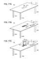
- FIG. 17 Another aspect of the invention is directed to a desk with an illumination function, the desk including a top board having a surface to be an illumination object, a top board support section adapted to support the top board, and a lighting equipment of one of the above aspects, such as preferably comprising an illumination section capable of illuminating the surface to be the illumination object, an image projection section capable of projecting an image on the surface to be the illumination object, a control section adapted to electrically control the illumination section and the image projection section, a housing section provided to the top board, and capable of housing the illumination section and the image projection section, and an arm section intervening between the illumination section and the housing section, and making it possible to selectively set either one of a non-use state in which the illumination section and the image projection section are housed in the housing section, and a usable state in which the illumination section and the image projection section are taken out from the housing section.
- a lighting equipment of one of the above aspects, such as preferably comprising an illumination section capable of illuminating the surface to be the illumination
- the desk with an illumination function of the aspect of the invention since it is possible to perform not only the illumination but also the image projection, a variety of usages become available. For example, an image can easily be projected on the desktop surface (the surface of the top board).
- a meeting around a desk e.g., a conference table
- the images necessary for the meeting can easily be projected on the desktop surface, and thus it is possible to smoothly proceed the meeting.
- the housing section capable of housing the illumination section and the image projection section is provided to the top board, when the illumination section and the image projection section are not used, it is possible to set the state in which illumination section and the image projection section are housed in the housing section. Further, in the case of using the illumination section or the image projection section, the illumination section or the image projection section can be set to the usable state only by performing the operation of taking out the illumination section and the image projection section, which are housed in the housing section, from the housing section.
- Fig. 1 is an exemplary diagram showing an appearance configuration of a lighting equipment according to a first embodiment of the invention.
- Fig. 2 is an exemplary diagram schematically showing a configuration of an optical system of an image projection section shown in Fig. 1 .
- Fig. 3 is an exemplary block diagram for explaining the electrical control of the lighting equipment according to the first embodiment.
- Fig. 4 is an exemplary diagram showing an installation example of the lighting equipment according to the first embodiment.
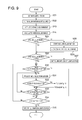
- Fig. 5 is an exemplary flowchart showing a basic operation of the lighting equipment according to the first embodiment for the purpose of the explanation thereof.
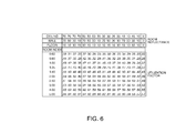
- Fig. 6 is an exemplary diagram showing a utilization factor table from which the utilization factor can be obtained based on the room reflectance and the room index.
- Fig. 7 is an exemplary diagram showing an appearance configuration of a lighting equipment according to a second embodiment of the invention.
- Fig. 8 is an exemplary block diagram for explaining the electrical control of the lighting equipment according to the second embodiment.
- Fig. 9 is an exemplary flowchart for explaining an operation in the lighting equipment according to the second embodiment.
- Fig. 10 is an exemplary flowchart for explaining the flow of the process in the case in which the user performs the menu selection in the step S32 in the flowchart shown in Fig. 9 .
- Figs. 11A and 11B are exemplary diagrams showing a lighting equipment according to a third embodiment of the invention for the purpose of the explanation thereof.
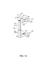
- Fig. 12 is an exemplary diagram showing mainly an arm section of the lighting equipment according to the third embodiment in an enlarged manner.
- Figs. 13A through 13C are exemplary diagrams for explaining an operation example for making it possible to selectively set an illumination section or an image projection section to either one of a non-use state and a usable state.
- Figs. 14A and 14B are exemplary diagrams for explaining an operation example for making it possible to selectively set the illumination section or the image projection section to either one of the non-use state and the usable state.
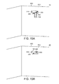
- Figs. 15A and 15B are exemplary diagrams showing the lighting equipment according to a fourth embodiment of the invention for the purpose of the explanation thereof.
- Figs. 16A and 16B are exemplary diagrams showing a modified example of the lighting equipment according to the fourth embodiment for the purpose of the explanation thereof.
- Figs. 17A through 17C are exemplary diagrams showing a desk with an illumination function according to a fifth embodiment of the invention for the purpose of the explanation thereof.
- Fig. 18 is an exemplary diagram showing the case of forming the image projection section to be of a lamp type for the purpose of the explanation thereof.
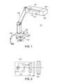
- Fig. 1 is a diagram showing an exemplary appearance configuration of a lighting equipment 10 according to a first embodiment of the invention.
- the lighting equipment 10 according to the first embodiment is provided with an illumination section 100 capable of illuminating a surface (e.g., a surface of a desk, table, etc.) to be an illumination object, an image projection section 200 disposed adjacent to the illumination section 100 so as to be able to project an image on the surface to be the illumination object, an arm section 300 for supporting the illumination section 100 so as to be able to adjustably move the illumination section 100 in, for example, a horizontal direction and/or a vertical direction relative to the surface to be the illumination object, a fixation section 400 for fixing the lighting equipment 10 according to the first embodiment to a desk and so on, an operation section 500 capable of a variety of types of operations, and a connecting cord 600 connectable to an electrical outlet (not shown).
- an illumination section 100 capable of illuminating a surface (e.g., a surface of a desk, table, etc.) to
- the illumination section 100 has a distance measurement section 120 for measuring the distance to the surface to be the illumination object
- the image projection section 200 has a projection lens 230.
- the arm section 300 is exemplarily assumed to be an adjustable arm. Therefore, the "arm section 300" may also be described as an “adjustable arm 300" in some cases.
- Fig. 1 there is adopted the configuration in which the image projection section 200 is adjacent to the illumination section 100, it is also possible to adopt the configuration in which some object intervenes between the illumination section 100 and the image projection section 200 instead of the adjacent configuration.
- the illumination section 100 has a light source 110 (hereinafter referred to as an illumination light source 110) inside, and functions as a normal lighting equipment by lighting the illumination light source 110.
- the illumination light source 110 is not particularly limited, but different kinds of light sources and combinations thereof can be used such as e.g. an incandescent bulb, a fluorescent lamp, an LED lamp and so on.
- the image projection section 200 is disposed integrally with the illumination section 100, and is arranged to be able to be moved (translated) together with the illumination section 100.
- the operation section 500 has a main switch 510 functioning as a basic switch of the lighting equipment 10 according to the first embodiment, and an image projection start switch 520 for making the start of the image projection possible. It should be noted that although not shown the operation section 500 is also provided with a variety of types of operation buttons such as a button for focus adjustment besides these switches.
- the main switch 510 is a switch for lighting the illumination light source 110 of the illumination section 100, and at the same time starting up a control section 550 (see Fig. 3 ) to thereby make a variety of types of control possible. It should be noted that the control performed by the control section 550 will be described later. Further, the image projection start switch 520 is a switch for starting the projection of the image by the image projection section 200.
- Fig. 2 is a diagram schematically showing a configuration of an optical system of the image projection section 200 shown in Fig. 1 .
- the image projection section 200 exemplarily has substantially the same configuration as a single plate liquid crystal projector, and has a light source section 210, a liquid crystal light modulation element 220, and a projection lens 230.
- the light source section 210 is provided with a light source 211 (hereinafter referred to as an image projection light source 211) formed e.g. of a white light emitting diode and so on, a collimator optical system 212, and a polarization conversion element 213. Although the detailed explanation is omitted here, the image projection light source 211 emits the colored light including e.g. red light, green light, and blue light.
- the collimator optical system 212 is an optical element for collimating the light emitted from the image projection light source 211.
- the polarization conversion element 213 is an element for performing the polarization conversion on the light transmitted through the collimator optical system 212.
- the polarization conversion element 213 has a polarization split layer for transmitting one linearly polarized component out of the polarization components of the incident light without modification while reflecting the other linearly polarized component in a direction perpendicular to a light axis 210ax, a reflecting layer for reflecting the other linearly polarized component, which has been reflected by the polarization split layer, in a direction parallel to the light axis 210ax, and a wave plate for converting the other linearly polarized component having been reflected by the reflecting layer into the one linearly polarized component.
- the liquid crystal light modulation element 220 is a light modulation device for modulating the light from the light source section 210 in accordance with the image information to be projected to thereby form a full-color image.
- the liquid crystal light modulation element 220 has a color filter (not shown).
- the color filter is formed of a Bayer arrangement color filter having a reflective dichroic filter, and has a function as a color separation optical system for separating the light from the light source section 210 into the red light, the green light, and the blue light pixel by pixel. It should be noted that other color separation optical systems can also be used as the color separation optical system.
- the liquid crystal light modulation element 220 further includes an entrance side polarization plate (not shown) disposed on the polarization conversion element 213 side, and an exit side polarization plate (not shown) disposed on the projection lens 230 side.
- the entrance side polarization plate, the liquid crystal light modulation element 220, and the exit side polarization plate perform the light modulation of the respective colored lights.
- the liquid crystal light modulation element 220 described above is driven by a liquid crystal light modulation element drive section 221 (see Fig. 3 ).
- the projection lens 230 projects the image thus formed by the liquid crystal light modulation element 220 on a projection surface in an enlarged manner.
- Fig. 3 is an exemplary block diagram for explaining the electrical control of the lighting equipment 10 according to the first embodiment.
- the lighting equipment 10 according to the first embodiment has the control section 550, and when the main switch 510 or the image projection start switch 520 is operated, the control section 550 controls the illumination light source 110, the image projection light source 211, the distance measurement section 120, the liquid crystal light modulation element drive section 221, and so on in accordance with the operation of the main switch 510 and/or the image projection start switch 520.
- control section 550 When the main switch 510 is set to the ON state, the control section 550 puts on the illumination light source 110 of the illumination section 100, and at the same time issues a distance measurement instruction to the distance measurement section 120. Thus, the distance measurement section 120 performs the measurement of the distance to the surface to be the illumination object. Further, a variety of types of control to the image projection section 200 are made possible. It should be noted that it is assumed that in the step in which the main switch 510 is set to the ON state, it becomes possible for the control section 550 to control lighting/extinction of the image projection light source 211 of the image projection section 200. It should be noted that it is assumed that the control (the control of driving the liquid crystal light modulation element 220 based on the image information to be projected) for projecting the actual image is enabled by setting the image projection start switch 520 to the ON state.
- control section 550 has a function of calculating the average illuminance of the surface to be the illumination object based on the distance measured by the distance measurement section 120 besides the function of controlling the illumination light source 110, the distance measurement section 120, the image projection light source 211, and the liquid crystal light modulation element drive section 221 described above.
- control section 550 has, for example, a Web information acquisition function capable of obtaining information existing in the Web (e.g. the Internet, or other local and/or remote computer networks), and a communication function capable of receiving broadcasting signal data such as e.g. television broadcasting (hereinafter referred to as TV broadcasting).
- TV broadcasting e.g. television broadcasting
- control section 550 has a storage section (not shown).
- Fig. 4 is an exemplary diagram showing an installation example of the lighting equipment 10 according to the first embodiment.
- the lighting equipment 10 according to the first embodiment is attached to a desk 700. Therefore, in the lighting equipment 10, the surface to be the illumination object corresponds to a desktop surface 710 of the desk 700. Further, the image projection section 200 is attached to the illumination section 100 so that it becomes possible to project the image on the surface (the desktop surface 710) to be the illumination object.
- Fig. 5 is an exemplary flowchart showing a basic operation of the lighting equipment 10 according to the first embodiment for the purpose of the explanation thereof. It should be noted that the flowchart shown in Fig. 5 is mainly for explaining the action performed by the control section 550, but partially includes the operation performed by the user.
- step S1 When the main switch 510 is set (step S1) to the ON state by the user, the control section 550 puts on (step S2) the illumination light source 110.
- the lighting equipment 10 is set to the state of functioning as the illumination, and at the same time is set to the state in which the control of the image projection light source 211 of the image projection section 200 is possible.
- the control section 550 issues (step S3) the distance measurement instruction to the distance measurement section 120, and then calculates (step S4) the average illuminance of the surface to be the illumination object, namely the desktop surface 710, using the distance thus measured.
- the control section 550 determines whether or not the average illuminance thus calculated is in an appropriate range, and then performs (steps S5 through S9) the illuminance adjustment so as to set the average illuminance within the appropriate illuminance range based on the determination result.
- the range (hereinafter referred to as an appropriate illuminance range) of the appropriate illuminance for the average illuminance of the desktop surface 710 in the desk 700 is regarded as the range of 500 through 1000 lx (lux). Therefore, here, the control section 550 determines whether or not the average illuminance of the desktop surface 710 is within the range of 500 through 1000 lx, and then performs the illuminance adjustment based on the determination result.
- control section 550 firstly determines (step S5) whether or not the average illuminance is equal to or higher than 500 lx, and if the average illuminance is equal to or higher than 500 lx (in the case of "Yes” in the step S5), the control section 550 determines (step S6) whether or not the average illuminance is equal to or lower than 1000 lx.
- the control section 550 controls (step S7) the brightness of the light source (the illumination light source 110 in this case) so that the average illuminance falls within the appropriate illuminance range (the range of 500 through 1000 lx).
- the control section 550 puts on the image projection light source 211 of the image projection section 200, and makes the image projection section 200 function as an auxiliary illumination section.
- the auxiliary illumination is started (step S8). It should be noted that on this occasion, the image projection section 200 performs the illumination on the desktop surface 710 with white light.
- control section 550 recalculates (step S9) the average illuminance in this state, and then determines (step S6) whether or not the average illuminance (the average illuminance obtained by adding the average illuminance due to the illumination section 100 and the average illuminance due to the image projection section 200) obtained by the recalculation is equal to or lower than 1000 lx.
- the control section 550 controls (step S7) the brightness of the light source so that the average illuminance falls within the appropriate illuminance range (the range of 500 through 1000 lx). It should be noted that although the control of the brightness of the light source performed here is the control of dropping the brightness of at least either one of the illumination light source 110 and the image projection light source 211, it is preferable to drop the brightness of the illumination light source 110 in this case.
- the "brightness of the illumination light source 110" may be described as the “brightness of the illumination section 100" in some cases
- the "brightness of the image projection light source 211” may be described as the "brightness of the image projection section 200" in some cases.
- control section 550 determines (step S10) whether or not the image projection start switch 520 is in the ON state, and if the image projection start switch 520 is not in the ON state (in the case of "No” in the step S10), the control section 550 determines (step S13) whether or not the main switch 510 is in the OFF state.
- the control section 550 puts off the illumination light source 110 and the image projection light source 211.
- control section 550 determines again whether or not the image projection start switch 520 is in the ON state.
- the control section 550 In contrast, if the image projection start switch 520 is set to the ON state in the step S10 (in the case of "Yes" in the step S10), the control section 550 generates the image to be projected by modulating the light from the image projection light source 211 based on the image information corresponding to the image to be projected, and then projects (step S11) the image thus generated. For example, if the acquisition of the information from a Web site is possible, the control section 550 projects the image based on the information obtained from the Web site on the desktop surface 710. It should be noted that the focus adjustment of the projection lens 230 in the case of projecting the image on the desktop surface 710 becomes possible by, for example, operating a focus adjustment button (not shown).
- control section 550 determines (step S12) whether or not the image projection start switch 520 is in the OFF state, and continues the image projection if the image projection start switch 520 is not in the OFF state (in the case of "No” in the step S12), or stops the image projection if the image projection start switch 520 is in the OFF state (in the case of "Yes” in the step S12). Then, the control section 550 determines (step S13) whether or not the main switch 510 is in the OFF state.
- the illuminance sensor is disposed on the desktop surface 710, and the illuminance sensor is covered by, for example, a notebook or a textbook, and thus it is unachievable to detect an appropriate average illuminance.
- the average illuminance of the desktop surface 710 is obtained by Formula 1 below, and the illuminance adjustment (the steps S5 through S9) is performed based on the average illuminance thus obtained.
- average illluminance lx ) lamp luminous flux lm ⁇ the number of light sources of the illumination section ⁇ the number of illumination sections ⁇ utilization factor ⁇ maintenance factor / the area of desktop surface m 2
- the lamp luminous flux as a light source (lumen (lm)
- the maintenance factor denotes a numerical value representing the deterioration of the luminous flux (lm) of the lamp with the elapse of time due to the grime of the lamp caused by the environment, and the numerical value can be set in accordance with, for example, the condition of the dust in the use environment.
- the maintenance factor can be set to "0.74" if the use environment is preferable, or can be set to "0.70" if the use environment is standard, or can be set to "0.62" if the use environment is bad.
- the utilization factor is known in Formula 1, the average illuminance can be obtained.
- the utilization factor is obtained from the utilization factor table shown in Fig. 6 .
- the exemplary utilization factor table shown in Fig. 6 is arranged so that the utilization factor can be obtained based on the room reflectance and the room index.
- the room reflectance is a value set in accordance with the material, the color, and so on of the ceiling, the walls, and the floor of the room where the desk 700 is installed. It should be noted that the "floor” can be substituted with the desktop surface 710 of the desk 700.
- the reflectance of the ceiling of the room where the desk 700 is installed is "70 %”
- the reflectance of the walls thereof is “50 %”
- the reflectance of the desktop surface 710 is 10%.”
- the room index can be obtained by Formula 2 below. It should be noted here that since the surface to be the illumination object is the desktop surface 710, the room index is also referred to as a "desktop-surface index."
- the desktop - surface index the room index the area of the desktop surface / the depth of the desktop surface + the width of the desktop surface ⁇ the height of the illumination section
- the area of the desktop surface and “(the depth of the desktop surface)+(the width of the desktop surface)” are known data. Further, as “the height of the illumination section,” the value measured by the distance measurement section 120 can be used. By using these values, the desktop-surface index (the room index) can be obtained by Formula 2.
- the utilization factor is obtained from the utilization factor table shown in Fig. 6 based on the desktop-surface index and the room reflectance thus obtained. It should be noted that numbers of decimal places are exemplarily shown as the utilization factor in Fig. 6 .
- the desktop-surface index has been obtained by Formula 2 as "2.5.” Therefore, based on the desktop-surface index of "2.5" obtained by Formula 2, the reflectance of "70 %" of the ceiling of the room where the desk 700 is installed, the reflectance of "50 %" of the walls thereof, and the reflectance of "10 %" of the desktop surface 710, the utilization factor of "0.58" can be obtained from the utilization factor table shown in Fig. 6 .
- the average illuminance can be obtained by substituting the utilization factor thus obtained into Formula 1.
- the process of calculating the average illuminance in the step S4 of the flowchart shown in Fig. 5 is the process of calculating the average illuminance in the state in which the image projection section 200 does not perform the auxiliary illumination
- the average illuminance calculation (the average illuminance recalculation in the step S9) in the case in which the image projection section 200 performs the auxiliary illumination is performed, the total average illuminance obtained by adding the average illuminance due to the image projection section 200 to the average illuminance (the average illuminance calculated by Formula 1) due to the illumination section 100 is calculated.
- the average illuminance due to the image projection section 200 is calculated in the following manner. Specifically, since the projection luminance (lm) due to the projection section 200 has been determined, the average illuminance of the desktop surface 710 due to the image projection section 200 can be obtained as a value obtained by dividing "the projection luminance (lm)" by "the area (m 2 ) of the desktop surface 710.” Therefore, the average illuminance in the case in which the image projection section 200 performs the auxiliary illumination can be obtained as the total average illuminance obtained by adding the average illuminance of the desktop surface 710 due to the image projection section 200 obtained in such a manner as described above to the average illuminance (the average illuminance calculated by Formula 1 described above) due to the illumination section 100.
- the brightness of the illumination section 100 is dropped when performing the process of dropping the brightness of the light source in the step S7. This is because if the brightness (the luminance) of the image projection section 200 is dropped, the quality of the projection image projected by the image projection section 200 is made to degrade. Therefore, in the case of performing the illuminance adjustment of dropping the average illuminance, it is preferable to arrange that the brightness on the illumination section 100 side is dropped. Further, if the average illuminance of the desktop surface 710 is lower than 500 lx, it is also preferable to perform the control so as to increase the brightness of the illumination section 100 without varying the brightness of the image projection section 200.
- the image projection section 200 only as the auxiliary light source, namely the case in which the image projection section 200 does not perform the actual image projection, it is also possible to arrange that the brightness of the illumination section 100 is made to drop and at the same time the brightness of the image projection section 200 is also made to drop, and it is also possible to arrange that the brightness of the image projection section 200 alone is made to drop.
- the average illuminance of the desktop surface 710 is calculated, whether or not the average illuminance thus calculated is within the appropriate illuminance range is determined, and the illumination adjustment of making the average illuminance be within the appropriate illuminance range is performed based on the determination result, it is possible to hold the average illuminance of the desktop surface 710 within the appropriate illuminance range suitable for reading and writing such as e.g. when learning.
- the average illuminance of the desktop surface 710 is calculated, and if the average illuminance of the desktop surface 710 does not reach the lower limit value of the appropriate illuminance range as a result of determining whether or not the average illuminance calculated is within the appropriate illuminance range, the auxiliary illumination is performed by the image projection section 200. Therefore, it is possible to increase the illuminance of the desktop surface 710 to a high level.
- the auxiliary illumination is performed by the image projection section 200
- the brightness of the illumination section 100 is controlled so that the total average illuminance of the average illuminance due to the illumination section 100 and the average illuminance due to the image projection section 200 does not exceed the appropriate illuminance range. Therefore, the illuminance of the desktop surface 710 can be held within the appropriate illuminance range.
- the image projection can be performed by the image projection section 200 if necessary, it is possible to obtain, for example, information necessary for reading from such as learning from, for example, a Web site, and then project the information thus obtained on the desktop.
- the type of the image to be projected can be selected. It should be noted that it is assumed that the types of the images, which can be projected in the lighting equipment 20 according to the second embodiment, include the TV broadcasting, and memorandum information input by the user from a software keyboard or the like besides the information existing on the Web sites.
- the user can perform some sort of action (gesture), the imaging section 130 (see Fig. 7 ) images the action performed by the user, and then provides the imaged image data to the control section 550, and then the control section 550 performs predetermined control based on the imaged data.
- some sort of action gesture
- the imaging section 130 see Fig. 7
- the control section 550 performs predetermined control based on the imaged data.
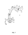
- Fig. 7 is an exemplary diagram showing an appearance configuration of the lighting equipment 20 according to the second embodiment.
- the lighting equipment 20 according to the second embodiment is different from the lighting equipment 10 according to the first embodiment in the point that the imaging section 130 and a sound output section (a speaker) 140 are provided, and the same constituents as those of the lighting equipment 10 according to the first embodiment are denoted with the same reference numerals.
- the installation positions of the imaging section 130 and the sound output section 140 are not limited to the positions shown in Fig. 7 .
- the optical system of the image projection section 200 has substantially the same configuration as that of the lighting equipment 10 according to the first embodiment.
- Fig. 8 is an exemplary block diagram for explaining the electrical control of the lighting equipment 20 according to the second embodiment. It should be noted that the configuration diagram shown in Fig. 8 is basically the same as Fig. 1 , but is different from the lighting equipment 10 according to the first embodiment in the point that the imaging section 130 and the sound output section 140 are provided.
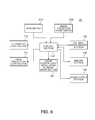
- Fig. 9 is an exemplary flowchart for explaining an operation in the lighting equipment 20 according to the second embodiment. Similarly to the flowchart shown in Fig. 5 , the flowchart shown in Fig. 9 is mainly for explaining the action performed by the control section 550, but partially includes the operation performed by the user. It should be noted that since the steps S21 through S30 are the same as the steps S1 through S10 in Fig. 5 , the explanation therefor will be omitted.
- step S30 The case (the case of "Yes” in the step S30) in which it is determined in the flowchart shown in Fig. 9 that the image projection start switch 520 is in the ON state will be explained.
- a selection screen (exemplarily referred to as a menu selection screen) with which the type of the image to be projected can be selected is projected (step S31).
- the control section 550 determines (step S32) whether or not the user has selected the type of the image from the menu selection screen.
- step S32 if the user has selected the type of the image (in the case of "Yes” in the step S32), the process proceeds to a pass "A" (see Fig. 10 ), and if the user has not selected the type of the image (in the case of "No” in the step S32), whether or not the image projection start switch 520 is in the OFF state is determined (step S33). If the image projection start switch 520 is in the OFF state (in the case of "Yes” in the step S33), whether or not the main switch 510 is in the OFF state is determined (step S34). Since the step S34 and the steps following from the step S34 are the same as the process of the step S13 and the steps following therefrom in Fig. 5 , the explanation therefor will be omitted.
- Fig. 10 is an exemplary flowchart for explaining the flow of the process in the case in which the user selects the type of the image from the menu selection screen. It should be noted that it is exemplarily assumed that in the menu selection screen the three types of "Web information," “TV broadcasting,” and “memorandum information" are prepared as the selectable image types, and it is arranged that the user can select either one of the three types described above.
- the user performs the action of indicating the type of the image displayed on the menu selection screen with a finger or the like.
- the action performed by the user is imaged by the imaging section 130, and the imaged data thereof is provided to the control section 550.
- the control section 550 determines what image the user has selected.
- step S41 in the case in which whether or not the user has selected the "Web information" is determined (step S41), and the user has selected the Web information (in the case of "Yes” in the step S41), the Web information selected by the user is projected (step S42).
- the Web information selected by the user is projected (step S42).
- step S43 whether or not the user performs some sort of control action (e.g., a page-turning action of the material) is determined (step S43), and if the user performs some sort of control action (in the case of "Yes" in the step S43), the screen control corresponding to the control action performed by the user is performed (step S44).
- the screen control corresponds to, for example, the control of turning the page of the material in accordance with the page-turning action in response to the user performing the action.
- the action (the page-turning action) performed by the user is imaged by the imaging section 130, and the control section 550 determines the action by the user based on the imaged data output from the imaging section 130 and then performs the screen control of turning the page of the material in accordance with the action of turning the page performed by the user.
- control section 550 determines (step S45) whether or not there exists a projection termination instruction of the image presently projected, namely the image (referred to as a selected image) selected from the menu selection screen.
- the control section 550 determines that there exists the projection termination instruction of the selected image (in the case of "Yes” in the step S45), the control section 550 terminates the projection of the selected image, and at the same time terminates (step S46) the output of the sound when the output of the sound is performed. Then, the process subsequently proceeds to the path "B," and then the step S33 in Fig. 9 is performed. It should be noted that if the projection termination instruction of the selected image does not exist in the step S45 shown in Fig. 10 (in the case of "No"), the process proceeds to the path "C1" to return to the step S42, and then the control section 550 continues the projection of the Web information.
- step S33 in Fig. 9 , whether or not the image projection start switch 520 is in the OFF state is determined in the step S33.
- the process proceeds to the step S34.
- the process proceeds to the step S31, and thus the menu selection becomes possible again.
- step S41 determines whether or not the information selected by the user is the "memorandum information” (step S47). Then, if the user selects the memorandum information (in the case of "Yes” in the step S47), the control section 550 projects (step S48) a memorandum information input screen (e.g., a software keyboard).
- a memorandum information input screen e.g., a software keyboard
- step S49 whether or not the user performs some sort of control action (e.g., an action of the user, inputting a character and so on, on the software keyboard) is determined (step S49), and if it is determined that the user has performed some sort of control action (in the case of "Yes" in the step S49), the screen control corresponding to the control action is performed (step S50).
- the screen control in this case is the control of making the imaging section 130 image the action of the user, and then projecting the memorandum information by the control section 550 based on the imaged data output from the imaging section 130.
- step S45 determines whether or not there exists the projection termination instruction of the selected image selected from the menu selection screen. If the projection termination instruction of the selected image does not exist in the step S45 (in the case of "No” in the step S45), the process proceeds to the path "C2" to return to the step S48, and then the control section 550 continues the projection of the memorandum information input screen. It should be noted that the case in which the projection termination instruction of the selected image exists (in the case of "Yes” in the step S45) in the step S45 is the same as described above, and therefore the explanation will be omitted.
- step S47 in Fig. 10 determines whether or not the user performs some sort of control action (e.g., a channel switching action) is determined (step S52), and if it is determined that the user has performed some sort of control operation (in the case of "Yes” in the step S52), the screen control corresponding to the control action is performed (step S53). In this case, the image of the channel designated by the user is projected.
- some sort of control action e.g., a channel switching action
- step S45 determines whether or not there exists the projection termination instruction of the selected image selected from the menu selection screen. If the projection termination instruction of the selected image does not exist in the step S45 (in the case of "No” in the step S45), the process proceeds to the path "C3" to return to the step S51, and then the control section 550 continues the projection of the TV broadcasting. It should be noted that the case in which the projection termination instruction of the selected image exists (in the case of "Yes” in the step S45) in the step S45 is the same as described above, and therefore the explanation will be omitted.
- the type of the image to be projected can be selected, and the image of the type thus selected is projected, there can be obtained an advantage that the usage as the lighting equipment having an image projection function can further be diversified in addition to the advantage obtained by the lighting equipment 10 according to the first embodiment.
- the three types of images namely the "Web information," the "TV broadcasting,” and the “memorandum information”
- the selectable image types are not limited to these types. For example, taking the case of attaching the lighting equipment 20 according to the second embodiment to a desk into consideration, it may be preferable in some case to remove the TV broadcasting from the selectable image types.
- Figs. 11A and 11B are exemplary diagrams showing the lighting equipment 30 according to a third embodiment for the purpose of an explanation thereof.
- Fig. 11A is a diagram showing the case of getting into the state (referred to as a usable state) in which the illumination section 100 and the image projection section 200 are taken out from a housing section 740
- Fig. 11B is a diagram showing the case of getting into the state (referred to as a non-use state) in which the illumination section 100 and the image projection section 200 are housed in the housing section 740.
- Fig. 12 is an exemplary diagram showing mainly the arm section 350 of the lighting equipment 30 according to the third embodiment in an enlarged manner.
- the lighting equipment 30 has a support member 720 for supporting the illumination section 100 in addition to the constituents such as the illumination section 100, the image projection section 200, and the operation section 500.
- the support member 720 has the surface to be the illumination object, and at the same time has the housing section 740 capable of housing the illumination section 100 and the image projection section 200. Further, the arm section 350 intervenes between the illumination section 100 and the housing section 740.
- the support member 720 corresponds to a desk, and in this case, the desk exemplarily corresponds to a table such as e.g. a "conference table.” Therefore, the support member 720 is hereinafter also exemplarily referred to as a "conference table 720."
- the surface to be the illumination object corresponds to the surface 731 (also referred to as a desktop surface 731) of a top board 730 of the conference table 720.
- the conference table 720 shown in Figs. 11A and 11B has the top board 731 shaped like a rectangle, the shape is not limited to a rectangle, but can be a variety of shapes such as a square or a circle, etc.
- the conference table 720 supports the illumination section 100 with the arm section 350 intervening between the housing section 740 and the illumination section 100.
- the arm section 350 is a sort of the adjustable arm, and for making it possible to selectively get into either of the non-use state in which the illumination section 100 and the image projection section 200 are housed in the housing section 740 and the usable state in which the illumination section 100 and the image projection section 200 are taken out from the housing section 740. It should be noted that structure and so on of the arm section 350 will be described later.
- the housing section 740 is arranged to be able to house the illumination section 100 and the image projection section 200 in the state in which the image projection section 200 is integrated with the illumination section 100. It should be noted that it is exemplarily assumed that the housing section 740 is disposed in the central portion of the desktop surface 731 of the conference table 720, but the present invention is not limited to disposing the housing section 740 in the central portion and it may also be disposed off of the central portion such as e.g. at a corner portion or edge portion of the desktop surface 731 of the conference table 720.
- the arm section 350 has a first arm 351 having the tip portion to which the illumination section 100 is attached, and a second arm 352 for supporting the first arm 351.
- the second arm 352 is supported in the base section (not shown) by a support mechanism (not shown) disposed in the housing section 740 so as to be rotatable within a predetermined angle range (assumed to be roughly 90 degrees) in the arrow a-a' direction shown in Fig. 12 .
- the second arm 352 telescopically supports the first arm 351 to thereby make it possible to house the first arm 351 inside the second arm 352 and to draw it out from the second arm 352.
- the first arm 351 supports the illumination section 100 so that the illumination section 100 is rotatable around the center axis ax1 of the first arm 351 (in the arrow b-b' direction) within a predetermined angle range. Further, the first arm 351 supports the illumination section 100 so that the illumination section 100 is rotatable around the center axis ax2 penetrating the first arm 351 side end portion of the illumination section 100 and the image projection section 200 side end portion thereof (in the arrow c-c' direction) within a predetermined angle range.
- the first arm 351 supports the illumination section 100 so that the illumination section 100 can be rotated around the center axis ax1 (in the arrow b-b' direction) within a predetermined angle range as described above, in the case in which the illumination section 100 and the image projection section 200 are set to the usable state (the state shown in Fig. 11A ), the illumination section 100 and the image projection section 200 can be moved on a plane along the desktop surface 731 so as to draw a circular arc. Thus, it is possible to arbitrarily change the position in the desktop surface 731 where the illumination or the projection is performed.
- the image projection section 200 is integrated with the illumination section 100, if, for example, the illumination section 100 is moved, the image projection section 200 is also moved together with the illumination section 100, and if the image projection section 200 is moved, the illumination section 100 is also moved together with the image projection section 200.
- the first arm 351 supports the illumination section 100 so that the illumination section 100 can be rotated around the center axis ax2 (in the arrow c-c' direction) within a predetermined angle range
- the illumination angle and the projection angle of the illumination section 100 and the image projection section 200 with respect to the desktop surface 731 can arbitrarily be changed within a predetermined range.
- the first arm 351 supports the illumination section 100 so as to be rotatable in a vertical direction. Specifically, the first arm 351 supports the illumination section 100 so as to make the illumination section 100 rotatable in a direction (an upward direction, the arrow d direction) in which the illumination section 100 gets away from the desktop surface 731 and a direction (a downward direction, the arrow d' direction) in which the illumination section 100 comes toward the desktop surface 731 within a predetermined angle range.
- the first arm 351 supports the illumination section 100 in such a manner as described above, the illumination angle and the projection angle of the illumination section 100 and the image projection section 200 with respect to the desktop surface 731 can arbitrarily be changed in a predetermined range. Further, it is possible to fold the illumination section 100 and the image projection section 200 when putting the illumination section 100 and the image projection section 200 into the housing section 740.
- the illumination section 100 when putting the illumination section 100 and the image projection section 200 into the housing section 740, the illumination section 100 is set to the state of being rotated approximately 90 degrees in a direction (the arrow d' direction) toward the desktop surface 731.
- the illumination light source 110 provided to the illumination section 100 is closely opposed in parallel to a side surface section 351a of the first arm 351.
- the illumination light source 110 provided to the illumination section 100 gets into the state of being closely opposed in parallel to a side surface section 352a of the second arm 352. It should be noted that the operation of setting the illumination section 100 to the state of being rotated approximately 90 degrees in the direction toward the desktop surface 731 can also be performed after putting the first arm 351 into the second arm 352.
- the arm section 350 is arranged to be capable of both of the telescopic action and the folding action, and by using such an arm section 350, it is possible to selectively set the illumination section 100 and the image projection section 200 to either one of the non-use state and the usable state. It should be noted that a specific example of an operation for making it possible to selectively set the illumination section 100 or the image projection section 200 to either one of the non-use state and the usable state will be described later.
- the configuration of the illumination section 100, the configuration of the image projection section 200, and the configuration of the operation section 500, and so on in the lighting equipment 30 according to the third embodiment substantially the same configurations (see, e.g., Figs. 1 and 2 ) as those in the lighting equipment 10 according to the first embodiment is adopted, and the same constituents as those of the lighting equipment 10 according to the first embodiment will be denoted with the same reference numerals.
- the configuration and the control action thereof for performing a variety of electrical control in the lighting equipment 30 according to the third embodiment can also be realized in such a manner as in the case of the lighting equipment 10 according to the first embodiment (see, e.g., Figs. 3 and 5 ).
- Figs. 13A through 13C , 14A, and 14B are exemplary diagrams for explaining an operation example for making it possible to selectively set the illumination section 100 and the image projection section 200 to either one of the non-use state and the usable state. It should be noted that since in the lighting equipment 30 according to the third embodiment, the image projection section 200 is integrated with the illumination section 100, the explanation of the operation for setting the illumination section 100 and the image projection section 200 to either one of the non-use state and the usable state in Figs. 13A through 13C , 14A, and 14B is assumed to be presented using the operation of either one of the illumination section 100 and the image projection section 200.
- Fig. 13A is an exemplary diagram showing the case in which the illumination section 100 and the image projection section 200 are set to the non-use state, and in such a non-use state, the first arm 351 is housed in the second arm 352, and the second arm 352 is housed in the housing section 740 in the folded state, and further the illumination section 100 and the image projection section 200 are also housed in the housing section 740 in the folded state.
- the second arm 352, the illumination section 100, and the image projection section 200 are prevented from getting into the state of projecting from the desktop surface 731 (see Fig. 11B ).
- the second arm 352 If the second arm 352 is rotated in the arrow "a" direction (see Fig. 13B ) while rotating the image projection section 200 in the arrow d direction in the state shown in Fig. 13A , the second arm 352 gets into the erect state (see Fig. 13C ) in due course. In this state, the first arm 351 is pulled out (see Fig. 14A ) from the second arm 352 in the upward direction (the arrow e direction).
- the image projection section 200 is rotated, for example, 90 degrees counterclockwise (in the arrow b' direction) around the center axis ax1 on a horizontal plane so that the illumination section 100 and the image projection section 200 are opposed to the position where the illumination is to be performed or the position where the image is to be projected in the desktop surface 731.
- the state shown in Fig. 14B is the state (the usable state) substantially the same as shown in Figs. 11A and 12 , and in the usable state, the illumination and the projection at a predetermined position on the surface (the desktop surface 731) to be the illumination object become available. It should be noted that in the usable state shown in Figs.
- the projection range in which the image projection section 200 performs the projection of the image can arbitrarily be set in accordance with, for example, the size of the surface (the desktop surface 731) to be the illumination object, but is preferably equivalent to, for example, the A5 size or A4 size through the A3 size or more.
- the first arm 351 is put into the second arm 352, and at the same time the illumination section 100 and the image projection section 200 are set to the folded state, and then the second arm 352 is laid to the housing section 740 side (in the arrow a' direction) to thereby be put into the housing section 740.
- the non-use state shown in Fig. 13A it is possible to set the non-use state shown in Fig. 13A .
- a lid (not shown in the lighting equipment 30 according to the third embodiment), which can open and close the housing section 740, to the housing section 740.
- the lid can be applied so as to cover the housing section 740.
- the lid may be opened, and then the operation shown in Figs. 13B, 13C , 14A, and 14B is performed.
- the desktop surface 731 can be used as a larger area when the illumination section 100 and the image projection section 200 are in the non-use state. Further, since the illumination section 100 and the image projection section 200 are not exposed, it becomes difficult for the dust to adhere to the illumination section 100 and the image projection section 200. Further, if a liquid such as a drink is spilt on the desktop surface 731, it becomes difficult for the illumination section 100 and the image projection section 200 to be directly splashed with the liquid, and therefore, it is possible to protect the illumination section 100 and the image projection section 200.
- the lid can also be a lid having a detachable structure, or can also be a lid having a structure slidable along the desktop surface 731, or can also be a lid having a structure having one side supported by the top board 730 with a hinge, and rotating within a predetermined angle range taking the hinge as an axis.
- the lighting equipment 30 according to the third embodiment is provided with the support member 720 (a table such as the conference table 720 in the lighting equipment 30 according to the third embodiment) having the surface to be the illumination object and the housing section 740 capable of housing the illumination section 100 and the image projection section 200, in addition to the constituents such as the illumination section 100, the image projection section 200, and the operation section 500, and therefore becomes suitable for the case of holding a meeting of a relatively small group while projecting an image.
- the support member 720 a table such as the conference table 720 in the lighting equipment 30 according to the third embodiment
- the housing section 740 capable of housing the illumination section 100 and the image projection section 200, in addition to the constituents such as the illumination section 100, the image projection section 200, and the operation section 500, and therefore becomes suitable for the case of holding a meeting of a relatively small group while projecting an image.
- the lighting equipment 30 if, for example, it is necessary to project an image when holding a meeting, only by performing the operation of taking out the illumination section 100 and the image projection section 200 from the housing section 740 of the conference table 720 as the support member, it is possible to set the image projection section 200 to the usable state.
- an appropriate size e.g., the size equivalent to the A5 size or A4 size through the A3 size or larger
- the lighting equipment 30 it is possible to project the images in the vicinity of the central portion of the conference table 720.
- the illumination section 100 and the image projection section 200 are arranged to be able to rotate within a predetermined angle range on a plane along the desktop surface 731. Therefore, by appropriately rotating the illumination section 100 and the image projection section 200 on the plane along the desktop surface 731, it is possible for the participants of the meeting sitting at any positions to easily view the images thus projected. Thus, it becomes easy for all of the participants of the meeting to share the information to thereby proceed the meeting smoothly.
- the conference table is exemplified as the support member 720 in the lighting equipment 30 according to the third embodiment
- a desk such as a student desk or an office desk, a table for business negotiation in an outlet store or the like, a table for a front desk window installed in a front desk window of a financial institution, a hotel, and further a leisure facility, and so on besides the conference table.
- the support member 720 is the table for business negotiation in an outlet store or the like
- the sales person it is possible for the sales person to provide the explanation while viewing the image projected, and for the customer to listen to the explanation while viewing the image projected. Therefore, it becomes easy for the sales person to provide the explanation, and it becomes easy for the customer to understand the content thus explained.
- control of the brightness of the light source, the control for obtaining the image to be projected, and so on can also be performed in the lighting equipment 30 according to the third embodiment similarly to the lighting equipment 10 according to the first embodiment. Further, it is also possible to perform the illumination alone without performing the projection of an image in the lighting equipment 30 according to the third embodiment similarly to the lighting equipment 10 according to the first embodiment, and further it is possible to use the image projection section 200 as the auxiliary illumination section of the illumination section 100.
- the configuration of the illumination section 100, the configuration of the image projection section 200, and the electrical control of the lighting equipment 30 according to the third embodiment are made substantially the same as those of the lighting equipment 10 according to the first embodiment
- Figs. 15A and 15B are exemplary diagrams showing a lighting equipment 40 according to a fourth embodiment of the invention for the purpose of an explanation thereof.
- Fig. 15A is a diagram showing the case of getting into the state (the usable state) in which the illumination section 100 and the image projection section 200 are taken out from a housing section 840
- Fig. 15B is a diagram showing the case of getting into the state (the non-use state) in which the illumination section 100 and the image projection section 200 are housed in the housing section 840.
- the point in which the lighting equipment 40 according to the fourth embodiment is different from the lighting equipment 30 according to the third embodiment is that a wall (referred to as a "wall 800" in the lighting equipment 40 according to the fourth embodiment) is used as the support member for supporting the illumination section 100 in the lighting equipment 40 according to the fourth embodiment although the desk (the conference table 720) is used as the support member for supporting the illumination section 100 in the lighting equipment 30 according to the third embodiment, and the lighting equipment 40 according to the fourth embodiment is the same as the lighting equipment 30 according to the third embodiment in the other points. Therefore, the same constituents are denoted with the same reference numerals. Further, in this case, the surface to be the illumination object corresponds to the surface 810 (referred to as a wall surface 810) of the wall 800.
- the housing section 840 is provided to the wall surface 810. As shown in Figs. 15A and 15B , the housing section 840 is disposed so that the longitudinal direction of the housing section 840 coincides with a horizontal direction (a direction along a horizontal line) in the wall surface 810. Further, the arm section 350 is attached to the housing section 840, and the illumination section 100 is attached to the arm section 350.
- the configuration of the arm section 350, the way of attaching the illumination section 100 to the arm section 350, and so on are substantially the same as those in the lighting equipment 30 according to the third embodiment, and further, the configuration of the housing section 840 is also substantially the same as that of the housing section 740 in the lighting equipment 30 according to the third embodiment.
- the operation for setting the illumination section 100 and the image projection section 200 to either of the usable state and the non-use state can be performed using the operation shown in Figs. 13A through 13C , 14A, and 14B .
- a lid (not shown in the lighting equipment 40 according to the fourth embodiment), which can open and close the housing section 840, to the housing section 840.
- the lighting equipment 40 related to the fourth embodiment in the case in which, for example, the conference table is installed in the vicinity of the wall surface 810, and a meeting is held using the conference table, it is possible to set the illumination section 100 and the image projection section 200 to the usable state only by performing the operation of taking out the illumination section 100, which is housed in the housing section 840 disposed on the wall surface 810, from the housing section 840.
- an appropriate size e.g., the size equivalent to the A5 size or A4 size through the A3 size or larger
- the lighting equipment 40 according to the fourth embodiment can also be used for a variety of usages besides a meeting.
- the lighting equipment 40 can be preferably used in the case of, for example, displaying some information for a predetermined period of time in a public facility or an office in order to inform the general public of the information.
- control of the brightness of the light source can also be performed in the lighting equipment 40 according to the fourth embodiment similarly to the lighting equipment 10 according to the first embodiment.
- control the illumination alone without performing the projection of an image in the lighting equipment 40 according to the fourth embodiment similarly to the lighting equipment 10 according to the first embodiment, and it is possible to use the image projection section 200 as the auxiliary illumination section.
- Figs. 16A and 16B are exemplary diagrams showing a modified example of the lighting equipment 40 according to the fourth embodiment for the purpose of an explanation thereof.
- the modified example (referred to as a lighting equipment 40a) of the lighting equipment 40 according to the fourth embodiment is arranged to have the housing section 840 the longitudinal direction of which coincides with a vertical direction (a direction along a vertical line) in the wall surface 810 as shown in Figs. 16A and 16B , and is substantially the same as the lighting equipment 40 according to the fourth embodiment shown in Figs. 15A and 15B in the other points.
- the lighting equipment 40a shown in Figs. 16A and 16B can be used in substantially the same manner as the lighting equipment 40 according to the fourth embodiment.
- Figs. 17A through 17C are exemplary diagrams showing a desk 50 with an illumination function according to a fifth embodiment of the invention for the purpose of the explanation thereof.
- the desk 50 with an illumination function according to the fifth embodiment is, for example, a conference table, and is provided with a top board 910 having a surface to be the illumination object, a top board support section 920 for supporting the top board 910, the illumination section 100 capable of illuminating the surface to be the illumination object, the image projection section 200 capable of projecting an image on the surface to be the illumination object, the operation section 500 capable of a variety of operations, a housing section 940 provided to the top board 910 and capable of housing the illumination section 100 and the image projection section 200, and the arm section 350 intervening between the illumination section 100 and the housing section 940 and for making it possible to selectively achieve either one of the non-use state in which the illumination section 100 and the image projection section 200 are housed in the housing section 940 and the usable state in which the illumination
- top board support section 920 is formed of four legs, the top board support section 920 is not limited to the legs, but can also be a sort of pedestal section.
- the same constituents as those of the lighting equipment 30 according to the third embodiment are denoted with the same reference numerals. Therefore, the illumination section 100, the image projection section 200, and the arm section 350 have the same configurations as those of the illumination section 100, the image projection section 200, and the arm section 350 in the lighting equipment 30 according to the third embodiment. Further, the housing section 940 provided to the desk 50 with an illumination function according to the fifth embodiment has the same configuration as that of the housing section 740 in the lighting equipment 30 according to the third embodiment.
- the housing section 940 is provided with a lid 950 capable of opening and closing the housing section 940.
- the lid 950 is assumed to be a detachable lid.
- control section 550 for electrically controlling the illumination section 100 and the image projection section 200, the connecting cord connectable to the electrical outlet, and so on are also provided.
- Fig. 17A is a diagram showing the state (the non-use state) in which the illumination section 100 and the image projection section 200 are housed in the housing section 940, and in which the housing section 940 is covered by the lid 950
- Fig. 17B is a diagram showing the state in which the lid 950 is removed in the state shown in Fig. 17A
- Fig. 17C is a diagram showing the state (the usable state) in which the illumination section 100 and the image projection section 200 are taken out from the housing section 940.
- the housing section 940 disposed on the surface 911 (also referred to as a desktop surface 911) of the top board 910 can be covered by the lid 950 as shown in Fig. 17A .
- the housing section 940 By covering the housing section 940 with the lid 940 as described above, it is possible to roughly flat the entire desktop surface 911 to thereby use the desktop surface 911 as a larger area. Further, since the illumination section 100 and the image projection section 200 are not exposed, it becomes difficult for the dust to adhere to the illumination section 100 and the image projection section 200. Further, if a liquid such as a drink is spilt on the desktop surface 911, it becomes difficult for the illumination section 100 and the image projection section 200 to be directly splashed with the liquid, and therefore, it is possible to protect the illumination section 100 and the image projection section 200.
- the detachable lid is exemplified as the lid 950 in the desk 50 with an illumination function according to the fifth embodiment, the detachable lid is not necessarily required.
- a lid having a structure slidable along the desktop surface 911 or a lid having a structure having one side supported by the top board 910 with a hinge, and rotating within a predetermined angle range taking the hinge as an axis.
- the lid 950 is detached as shown in Fig. 17B . It should be noted that it is sufficient for the lid 950 thus detached to be placed at a place where the lid 950 does not hinder the projection in the desktop surface 911 when the image projection section 200 performs the projection. Subsequently, the operation of taking out the illumination section 100 and the image projection section 200 is performed in the state shown in Fig. 17B . It should be noted that as the operation of taking out the illumination section 100 and the image projection section 200 in the state shown in Fig. 17B , it is sufficient to perform substantially the same operation as the operation shown in Figs. 13A through 13C , 14A, and 14B .
- the illumination section 100 and the image projection section 200 are set to the usable state as shown in Fig. 17C .
- the illumination section 100 and the image projection section 200 are set to the usable state as shown in Fig. 17C .
- the desk 50 with an illumination function according to the fifth embodiment configured as described above can be used in a similar manner to the lighting equipment 30 according to the third embodiment. Therefore, in also the desk 50 with an illumination function according to the fifth embodiment, substantially the same advantage as that of the lighting equipment 30 according to the third embodiment can be obtained.
- the appearance configurations and the shapes of the lighting equipments 10 through 40 according to the first through fourth embodiments, and the appearance configuration and the shape of the desk 50 with an illumination function according to the fifth embodiment are not limited to the appearance configurations and the shapes shown in the respective embodiments. Further, although in the lighting equipment 10 according to the first embodiment and the lighting equipment 20 according to the second embodiment, the case in which the illumination section 100 is attached to the adjustable arm 300 is exemplified, the illumination section 100 is not necessarily required to be attached to the adjustable arm 300, but is only required to be attached so as to be able to illuminate the surface to be the illumination object such as the desktop surface.
- the connecting section on the image projection section 200 side is connected to the connecting section on the illumination section 100 side to thereby arrange that the image projection section 200 and the illumination section 100 are structurally and electrically connected to each other. It should be noted that in this case, it is also possible to provide the communication function, which makes the communication with the outside possible, to the image projection section 200 side.
- the image projection section 200 can be of a lamp type.
- a light bulb attaching socket to which a general incandescent light bulb can be attached
- a connecting member (a cap) equivalent to the general incandescent light bulb on the image projection section 200 side as the respective connecting sections of the illumination section 100 and the image projection section 200 to thereby arrange that the image projection section 200 can be attached to the illumination section 100 in the similar way to the case of attaching the incandescent light bulb.
- Fig. 18 is an exemplary diagram showing the case of forming the image projection section 200 to be of a lamp type for the purpose of the explanation thereof. It should be noted that although the explanation is presented in Fig. 18 assuming that the illumination section 100 has substantially the same configuration as that of the illumination section 100 in the lighting equipment 10 according to the first embodiment, this configuration can also be put into practice in the case in which the illumination section 100 has substantially the same configuration as that of the illumination section 100 in either of the lighting equipments 20 through 40 according to the second through fourth embodiments, and the desk 50 with an illumination function according to the fifth embodiment.
- the illumination section 100 is provided with the light bulb attaching socket 190
- the image projection section 200 is provided with the cap 250 as the connecting member which can be connected to the light bulb attaching socket 190.
- the configuration of the optical system and so on of the image projection section 200 can be made substantially the same as that of the lighting equipment 10 according to the first embodiment.
- the configuration of the electrical control system can also be made substantially the same as those of the lighting equipment 10 according to the first embodiment and the lighting equipment 20 according to the second embodiment. It should be noted that in this case it is also possible to arrange that the communication function and so on are disposed on the image projection section 200 side.
- the housing section 740 in the lighting equipment 30 according to the third embodiment, the housing section 840 in the lighting equipment 40 according to the fourth embodiment, and the housing section 940 in the desk 50 with an illumination function according to the fifth embodiment to have a structure capable of housing the image projection section 200 formed as a separate member in addition to the illumination section 100.
- each of the housing sections 740, 840, and 940 has the structure capable of housing the image projection section 200 in each of the housing sections 740, 840, and 940 while being attached to the illumination section 100
- the image projection section 200 is housed in each of the housing sections 740, 840, and 940 while keeping the state in which the image projection section 200 is attached to the illumination section 100, and at the same time the image projection section 200 is housed in each of the housing sections 740, 840, and 940 also in the state (the state of the separate member) in which the image projection section 200 is not attached to the illumination section 100.
- a lens which has electrodes, and is expanded and contracted (varied in thickness) in accordance with the level of the voltage applied to the electrodes, and is thus capable of adjusting the focal distance (referred to as a focus adjustment), as the projection lens 230 of the image projection section 200, or it is also possible to adopt an automatic focus adjustment function using a servo motor, which is adopted in, for example, a digital camera.
- a servo motor which is adopted in, for example, a digital camera.
- the lens provided with the electrodes is known to the public, and there exists one having a lens thickness varied from 750 micrometers to 375 micrometers when applying a voltage of 20 volts to the electrodes, for example.
- the instructions of starting and stopping the image projection is arranged to be performed by the ON/OFF operation of the image projection start switch 520, it is also possible to arrange that regarding also the instructions of starting the image projection and stopping the image projection, the user performs some sort of action, the imaging section 130 images the action performed by the user, and then the control section 550 performs the control (starting the image projection or stopping the image projection) corresponding to the action of the user based on the imaged image data.
- the lighting equipment 10 according to the first embodiment and the lighting equipment 20 according to the second embodiment can be used in various fields such as an office desk or a conference table besides the desk.
- the arm section 350 used in the lighting equipment 30 according to the third embodiment, the lighting equipment 40 according to the fourth embodiment, and the desk 50 with an illumination function according to the fifth embodiment is assumed to have the structure (see, e.g., Fig. 12 ) capable of the telescopic and folding actions.
- the arm section 350 is not limited to those having such a structure, but arm sections with various structures can be adopted.
- citing the lighting equipment 30 according to the third embodiment as an example if the arm section 350 has a structure capable of a multiple folding action, it is possible to house the illumination section 100 and the image projection section 200 in the housing section 740 without having the telescopic structure.
- the illumination section 100 and the image projection section 200 may be housed in the housing section 740 only with the telescopic structure even without having the folding structure in some cases. Further, it is also possible to arrange that the action of housing the illumination section 100 and the image projection section 200 into the housing section 740 and the action of taking them out from the housing section 740 are performed in an electric-powered manner.
- the light modulation element is not limited thereto, but can be the light modulation element using a digital micromirror device.
- the light modulation element is not limited thereto, but can be the light modulation element using a digital micromirror device.
- Features, components and specific details of the structures of the above-described embodiments and modifications thereof may be exchanged or combined to form further embodiments optimized for the respective application.
- modifications are readily apparent for an expert skilled in the art they shall be disclosed implicitly by the above description without specifying explicitly every possible combination, for the sake of conciseness of the present description.
Abstract
Description
- The present invention relates to a lighting equipment having an illumination function and an image projection function, and a desk with an illumination function.
- In the past, there has been known a desktop lighting equipment having an illumination function and an image projection function (see, e.g.,
JP-A-8-163476 Patent Document 1 has a light source, a light modulation element for modulating the light from the light source based on the image information to be projected to thereby form the image, and a projection lens for projecting the image emitted from the light modulation element in an enlarged manner. - In the case of using the existing lighting equipment having such a configuration for an illumination purpose, it is arranged that the light from the light source is projected in the state of providing no image information to be projected, while in the case of using the lighting equipment for an image projection purpose, it is arranged that the image based on the image information to be projected is formed, and then the image thus formed is projected. Thus, the existing lighting equipment is made available for the illumination purpose, and at the same time, is made available for the image projection purpose. Further, the illumination angle and the projection angle of the existing lighting equipment can be set in an adjustable manner using an adjustable arm, and therefore, the existing lighting equipment is a lighting equipment assumed to be mainly used while being attached to, for example, a student desk or an office desk.
- However, in the case of using the existing lighting equipment for the illumination purpose while being attached to the student desk, the office desk, and so on, it is difficult to illuminate the surface (the surface of the desk) to be the illumination object so as to provide an appropriate illuminance throughout a wide range. This is because the existing lighting equipment has a configuration of using the same light source in both of the case of using the lighting equipment for the illumination purpose and the case of using it for the image projection purpose, and projecting an image in a limited range when projecting the image.
- On the other hand, regarding the desk such as the student desk or the office desk, and so on, it is preferable to perform illumination so as to provide the desk surface with an appropriate illuminance throughout a wide range. Therefore, there arises a problem that the existing lighting equipment is not suitable to be used for the desk such as the student desk or the office desk, and is therefore limited in use.
- An advantage of some aspects of the invention is to provide a lighting equipment and a desk with an illumination function each having the illumination function and the image projection function to thereby make a wide variety of uses possible, and at the same time, capable of providing an appropriate illuminance to the surface to be the illumination object throughout a wide range.
- [1] An aspect of the invention is directed to a lighting equipment including an illumination section capable of illuminating a surface to be an illumination object, an image projection section capable of projecting an image on the surface to be the illumination object, a control section adapted to electrically control the illumination section and the image projection section.
- According to the lighting equipment of the aspect of the invention, since the illumination function and the image projection function are provided, a variety of usages become available. Further, since the configuration of having both of the illumination section and the image projection section is adopted, it becomes possible for the illumination section to achieve the function as a general lighting equipment, and to provide appropriate illuminance to the surface to be the illumination object throughout a broad range. Therefore, the lighting equipment according to the aspect of the invention can be made to be a lighting equipment suitable for a desk such as a student desk or an office desk. It should be noted that "illuminance" in the aspect of the invention denotes the average illuminance on the surface to be the illumination object.
- [2] In the lighting equipment of the above aspect of the invention, it is preferable that the control section makes a light source of the image projection section light to thereby make the image projection section function as an auxiliary illumination section.
- By making the image projection section function as the auxiliary illumination section as described above, it is possible to provide the appropriate illuminance to the surface to be the illumination object throughout a broad range.
- [3] In the lighting equipment of the above aspect of the invention, it is preferable that the control section has a function of calculating illuminance of the surface to be the illumination object in a state in which the illumination section performs illumination, and a function of determining whether or not the illuminance calculated is within an appropriate illuminance range set as a range of an appropriate illuminance, and then performing an illuminance adjustment so that the illuminance falls within the appropriate illuminance range based on a result of the determination, and adjusts brightness of the illumination section so that the illuminance falls within the appropriate illuminance range.
- Thus, in the case of using the lighting equipment according to the aspect of the invention, for example, for a desk such as a student desk or an office desk, since the desktop surface forms the surface to be the illumination object, it is possible to provide the most suitable illuminance for performing learning or paperwork to the desktop surface throughout a broad range. Further, by obtaining the illuminance using the calculation, it becomes unnecessary to provide an illuminance sensor and so on to the desktop surface, and thus the effective use of the desktop surface can be achieved.
- [4] In the lighting equipment of the above aspect of the invention, it is preferable that the control section adjusts the brightness of the illumination section so that the illuminance falls within the appropriate illuminance range in one of a case in which the illuminance, which is obtained when the image projection section is made to function as the auxiliary illumination section, exceeds an upper limit value of the appropriate illuminance range, and a case in which the illuminance is lower than a lower limit value of the appropriate illuminance range.
- By performing the illuminance adjustment by adjusting the brightness on the illuminance section side as described above, if the image projection section performs the image projection, it is possible to avoid the degradation of the brightness (luminance) on the image projection section side, and therefore, there is no chance of affecting the quality of the image projected at that moment.
- [5] In the lighting equipment of the above aspect of the invention, it is preferable that the image projection section is disposed integrally with the illumination section.
- By adopting such a configuration, if the image projection is necessary, the image projection can promptly be performed, and therefore, the lighting equipment can be made user-friendly.
- [6] In the lighting equipment of the above aspect of the invention, it is preferable that the image projection section is detachably attached to the illumination section.
- By adopting such a configuration, if the image projection section is unnecessary, the image projection section can be detached. Therefore, in the state in which the image projection section is detached, it is possible to make the lighting equipment compact.
- [7] In the lighting equipment of the above aspect of the invention, it is preferable that the control section has a function of obtaining image information corresponding to the image to be projected from a network.
- Thus, if the information existing on the Web, for example, is made obtainable, necessary information can easily be displayed.
- [8] In the lighting equipment of the above aspect of the invention, it is preferable that the control section has a function of projecting a selection screen with which a type of the image to be projected can be selected.
- Thus, it is possible to display information of a variety of fields, and it is possible to further diversify the purpose of the lighting equipment according to the aspect of the invention.
- [9] In the lighting equipment of the above aspect of the invention, it is preferable that there is further provided an arm section adapted to support the illumination section.
- By adopting such a configuration, the lighting equipment according to the aspect of the invention can easily be attached to a desk and so on, and in the case of setting the state in which the lighting equipment is attached to the desk with the arm section, an appropriate distance can be held between the desktop surface, the illumination section and the image projection section.
- [10] In the lighting equipment of the above aspect of the invention, it is preferable that the arm section has an adjustable arm or even is an adjustable arm.
- By adopting such a configuration, in the case of attaching the lighting equipment according to the aspect of the invention to the desk or the like, since the illumination section and the image projection section can arbitrarily be moved on the desktop surface, the lighting equipment can be made user-friendly.
- [11] In the lighting equipment of the above aspect of the invention, it is preferable that there is further provided a support member including a housing section having the surface to be the illumination object, and capable of housing the illumination section and the image projection section, and adapted to support the illumination section, the arm section intervenes between the illumination section and the housing section, and makes it possible to selectively set either one of a non-use state in which the illumination section and the image projection section are housed in the housing section, and a usable state in which the illumination section and the image projection section are taken out from the housing section.
- By adopting such a configuration, in the case in which the illumination section and the image projection section are not used, the illumination section and the image projection section can be set to the non-use state by housing the illumination section and the image projection section in the housing section. Further, in the case of using the illumination section or the image projection section, the illumination section or the image projection section can be set to the usable state only by performing the operation of taking out the illumination section and the image projection section, which are housed in the housing section, from the housing section.
- [12] In the lighting equipment of the above aspect of the invention, it is preferable that the arm section has a structure capable of at least one of a telescopic action and a folding action, and makes it possible to selectively set either one of the non-use state and the usable state using the structure capable of at least one of the telescopic action and the folding action.
- Since the arm section has such a structure, the operation of housing the illumination section and the image projection section into the housing section, or the operation of taking out the illumination section and the image projection section from the housing section can easily be performed.
- [13] In the lighting equipment of the above aspect of the invention, it is preferable that the illumination section and the image projection section are arranged to be rotatable around the arm section on a plane along the surface to be the illumination object.
- By adopting such a configuration, it is possible to move the illumination section and the image projection section on the plane along the surface to be the illumination object so as to draw a circular arc, and thus, the position where the illumination or the projection is performed on the surface to be the illumination object can arbitrarily be changed.
- [14] In the lighting equipment of the above aspect of the invention, it is preferable that the support member is a desk, the surface to be the illumination object is a desktop surface of the desk, and the housing section is provided to the desktop surface.
- By adopting such a configuration, an image can easily be projected on the desktop surface. Thus, in the case of, for example, holding a meeting around a desk (e.g., a conference table) with a relatively small group, the images necessary for the meeting can easily be projected on the desktop surface, and thus it is possible to smoothly proceed the meeting. It should be noted that in the present specification, it is assumed that anything having a top board forming the desktop surface and a top board support section (leg sections or a pedestal section) for supporting the top board is a "desk" in a broad sense. Therefore, it is assumed that the desk includes a student desk, an office desk, a conference table, a table for business negotiation in an outlet store or the like, a table for a front desk window installed in a front desk window of a financial institution and a hotel, and further a leisure facility, and so on.
- [15] In the lighting equipment of the above aspect of the invention, it is preferable that the support member is a wall, the surface to be the illumination object is a surface of the wall, and the housing section is provided to the surface of the wall.
- By adopting such a configuration, an image can easily be projected on the surface of the wall (also referred to as a wall surface). Thus, in the case of, for example, holding a meeting, the images necessary for the meeting can easily be projected on the wall surface, and thus it is possible to smoothly proceed the meeting. It should be noted that the lighting equipment having such a configuration can also be used for a variety of usages besides the meeting. For example, the lighting equipment is preferably used in the case of, for example, displaying some information for a predetermined period of time in a public facility or an office in order to inform the general public of the information.
- [16] In the lighting equipment of the above aspect of the invention, it is preferable that the housing section has a lid capable of opening and closing the housing section, and the lid covers the housing section in the non-use state in which the illumination section and the image projection section are housed in the housing section.
- By providing such a lid, it is possible to roughly flat the entire surface to be the illumination object when the illumination section and the image projection section are in the non-use state. Further, since the illumination section and the image projection section are not exposed, it becomes difficult for the dust to be attached to the illumination section and the image projection section, and an advantage of protecting the illumination section and the image projection section can also be obtained. It should be noted that the lid can also be a lid having a detachable structure, or can also be a lid having a structure slidable along the surface of the top board, or can also be a lid having a structure having one side supported by the top board with a hinge, and rotating within a predetermined angle range taking the hinge as an axis.
- [17] Another aspect of the invention is directed to a desk with an illumination function, the desk including a top board having a surface to be an illumination object, a top board support section adapted to support the top board, and a lighting equipment of one of the above aspects, such as preferably comprising an illumination section capable of illuminating the surface to be the illumination object, an image projection section capable of projecting an image on the surface to be the illumination object, a control section adapted to electrically control the illumination section and the image projection section, a housing section provided to the top board, and capable of housing the illumination section and the image projection section, and an arm section intervening between the illumination section and the housing section, and making it possible to selectively set either one of a non-use state in which the illumination section and the image projection section are housed in the housing section, and a usable state in which the illumination section and the image projection section are taken out from the housing section.
- According to the desk with an illumination function of the aspect of the invention, since it is possible to perform not only the illumination but also the image projection, a variety of usages become available. For example, an image can easily be projected on the desktop surface (the surface of the top board). Thus, as described above, in the case of, for example, holding a meeting around a desk (e.g., a conference table) with a relatively small group, the images necessary for the meeting can easily be projected on the desktop surface, and thus it is possible to smoothly proceed the meeting.
- Further, according to the desk with an illumination function of the aspect of the invention, since the housing section capable of housing the illumination section and the image projection section is provided to the top board, when the illumination section and the image projection section are not used, it is possible to set the state in which illumination section and the image projection section are housed in the housing section. Further, in the case of using the illumination section or the image projection section, the illumination section or the image projection section can be set to the usable state only by performing the operation of taking out the illumination section and the image projection section, which are housed in the housing section, from the housing section.
- It should be noted that in also the desk with an illumination function according to the aspect of the invention, it is preferable to have the features [2] to [8], [10], [12], [13] and [16] described above, out of the features of the lighting equipment according to the aspect of the invention.
- The invention will be described with reference to the accompanying drawings, wherein like numbers reference like elements.
-
Fig. 1 is an exemplary diagram showing an appearance configuration of a lighting equipment according to a first embodiment of the invention. -
Fig. 2 is an exemplary diagram schematically showing a configuration of an optical system of an image projection section shown inFig. 1 . -
Fig. 3 is an exemplary block diagram for explaining the electrical control of the lighting equipment according to the first embodiment. -
Fig. 4 is an exemplary diagram showing an installation example of the lighting equipment according to the first embodiment. -
Fig. 5 is an exemplary flowchart showing a basic operation of the lighting equipment according to the first embodiment for the purpose of the explanation thereof. -
Fig. 6 is an exemplary diagram showing a utilization factor table from which the utilization factor can be obtained based on the room reflectance and the room index. -
Fig. 7 is an exemplary diagram showing an appearance configuration of a lighting equipment according to a second embodiment of the invention. -
Fig. 8 is an exemplary block diagram for explaining the electrical control of the lighting equipment according to the second embodiment. -
Fig. 9 is an exemplary flowchart for explaining an operation in the lighting equipment according to the second embodiment. -
Fig. 10 is an exemplary flowchart for explaining the flow of the process in the case in which the user performs the menu selection in the step S32 in the flowchart shown inFig. 9 . -
Figs. 11A and 11B are exemplary diagrams showing a lighting equipment according to a third embodiment of the invention for the purpose of the explanation thereof. -
Fig. 12 is an exemplary diagram showing mainly an arm section of the lighting equipment according to the third embodiment in an enlarged manner. -
Figs. 13A through 13C are exemplary diagrams for explaining an operation example for making it possible to selectively set an illumination section or an image projection section to either one of a non-use state and a usable state. -
Figs. 14A and 14B are exemplary diagrams for explaining an operation example for making it possible to selectively set the illumination section or the image projection section to either one of the non-use state and the usable state. -
Figs. 15A and 15B are exemplary diagrams showing the lighting equipment according to a fourth embodiment of the invention for the purpose of the explanation thereof. -
Figs. 16A and 16B are exemplary diagrams showing a modified example of the lighting equipment according to the fourth embodiment for the purpose of the explanation thereof. -
Figs. 17A through 17C are exemplary diagrams showing a desk with an illumination function according to a fifth embodiment of the invention for the purpose of the explanation thereof. -
Fig. 18 is an exemplary diagram showing the case of forming the image projection section to be of a lamp type for the purpose of the explanation thereof. - Hereinafter, some examples of the lighting equipment and the desk with an illumination function as embodiments of the invention will be explained.
-
Fig. 1 is a diagram showing an exemplary appearance configuration of alighting equipment 10 according to a first embodiment of the invention. Thelighting equipment 10 according to the first embodiment is provided with anillumination section 100 capable of illuminating a surface (e.g., a surface of a desk, table, etc.) to be an illumination object, animage projection section 200 disposed adjacent to theillumination section 100 so as to be able to project an image on the surface to be the illumination object, anarm section 300 for supporting theillumination section 100 so as to be able to adjustably move theillumination section 100 in, for example, a horizontal direction and/or a vertical direction relative to the surface to be the illumination object, afixation section 400 for fixing thelighting equipment 10 according to the first embodiment to a desk and so on, anoperation section 500 capable of a variety of types of operations, and a connectingcord 600 connectable to an electrical outlet (not shown). Further, theillumination section 100 has adistance measurement section 120 for measuring the distance to the surface to be the illumination object, and theimage projection section 200 has aprojection lens 230. It should be noted that thearm section 300 is exemplarily assumed to be an adjustable arm. Therefore, the "arm section 300" may also be described as an "adjustable arm 300" in some cases. - It should be noted that although in
Fig. 1 there is adopted the configuration in which theimage projection section 200 is adjacent to theillumination section 100, it is also possible to adopt the configuration in which some object intervenes between theillumination section 100 and theimage projection section 200 instead of the adjacent configuration. - The
illumination section 100 has a light source 110 (hereinafter referred to as an illumination light source 110) inside, and functions as a normal lighting equipment by lighting theillumination light source 110. Theillumination light source 110 is not particularly limited, but different kinds of light sources and combinations thereof can be used such as e.g. an incandescent bulb, a fluorescent lamp, an LED lamp and so on. - Further, the
image projection section 200 is disposed integrally with theillumination section 100, and is arranged to be able to be moved (translated) together with theillumination section 100. - The
operation section 500 has amain switch 510 functioning as a basic switch of thelighting equipment 10 according to the first embodiment, and an imageprojection start switch 520 for making the start of the image projection possible. It should be noted that although not shown theoperation section 500 is also provided with a variety of types of operation buttons such as a button for focus adjustment besides these switches. - The
main switch 510 is a switch for lighting theillumination light source 110 of theillumination section 100, and at the same time starting up a control section 550 (seeFig. 3 ) to thereby make a variety of types of control possible. It should be noted that the control performed by thecontrol section 550 will be described later. Further, the imageprojection start switch 520 is a switch for starting the projection of the image by theimage projection section 200. -
Fig. 2 is a diagram schematically showing a configuration of an optical system of theimage projection section 200 shown inFig. 1 . Theimage projection section 200 exemplarily has substantially the same configuration as a single plate liquid crystal projector, and has alight source section 210, a liquid crystallight modulation element 220, and aprojection lens 230. - The
light source section 210 is provided with a light source 211 (hereinafter referred to as an image projection light source 211) formed e.g. of a white light emitting diode and so on, a collimatoroptical system 212, and apolarization conversion element 213. Although the detailed explanation is omitted here, the image projectionlight source 211 emits the colored light including e.g. red light, green light, and blue light. - The collimator
optical system 212 is an optical element for collimating the light emitted from the image projectionlight source 211. Thepolarization conversion element 213 is an element for performing the polarization conversion on the light transmitted through the collimatoroptical system 212. Thepolarization conversion element 213 has a polarization split layer for transmitting one linearly polarized component out of the polarization components of the incident light without modification while reflecting the other linearly polarized component in a direction perpendicular to a light axis 210ax, a reflecting layer for reflecting the other linearly polarized component, which has been reflected by the polarization split layer, in a direction parallel to the light axis 210ax, and a wave plate for converting the other linearly polarized component having been reflected by the reflecting layer into the one linearly polarized component. - The liquid crystal
light modulation element 220 is a light modulation device for modulating the light from thelight source section 210 in accordance with the image information to be projected to thereby form a full-color image. The liquid crystallight modulation element 220 has a color filter (not shown). The color filter is formed of a Bayer arrangement color filter having a reflective dichroic filter, and has a function as a color separation optical system for separating the light from thelight source section 210 into the red light, the green light, and the blue light pixel by pixel. It should be noted that other color separation optical systems can also be used as the color separation optical system. - Further, the liquid crystal
light modulation element 220 further includes an entrance side polarization plate (not shown) disposed on thepolarization conversion element 213 side, and an exit side polarization plate (not shown) disposed on theprojection lens 230 side. The entrance side polarization plate, the liquid crystallight modulation element 220, and the exit side polarization plate perform the light modulation of the respective colored lights. The liquid crystallight modulation element 220 described above is driven by a liquid crystal light modulation element drive section 221 (seeFig. 3 ). - Further, the
projection lens 230 projects the image thus formed by the liquid crystallight modulation element 220 on a projection surface in an enlarged manner. -
Fig. 3 is an exemplary block diagram for explaining the electrical control of thelighting equipment 10 according to the first embodiment. Thelighting equipment 10 according to the first embodiment has thecontrol section 550, and when themain switch 510 or the imageprojection start switch 520 is operated, thecontrol section 550 controls theillumination light source 110, the image projectionlight source 211, thedistance measurement section 120, the liquid crystal light modulationelement drive section 221, and so on in accordance with the operation of themain switch 510 and/or the imageprojection start switch 520. - Then, the control performed by the
control section 550 will specifically be explained. When themain switch 510 is set to the ON state, thecontrol section 550 puts on theillumination light source 110 of theillumination section 100, and at the same time issues a distance measurement instruction to thedistance measurement section 120. Thus, thedistance measurement section 120 performs the measurement of the distance to the surface to be the illumination object. Further, a variety of types of control to theimage projection section 200 are made possible. It should be noted that it is assumed that in the step in which themain switch 510 is set to the ON state, it becomes possible for thecontrol section 550 to control lighting/extinction of the image projectionlight source 211 of theimage projection section 200. It should be noted that it is assumed that the control (the control of driving the liquid crystallight modulation element 220 based on the image information to be projected) for projecting the actual image is enabled by setting the imageprojection start switch 520 to the ON state. - Further, the
control section 550 has a function of calculating the average illuminance of the surface to be the illumination object based on the distance measured by thedistance measurement section 120 besides the function of controlling theillumination light source 110, thedistance measurement section 120, the image projectionlight source 211, and the liquid crystal light modulationelement drive section 221 described above. Further, thecontrol section 550 has, for example, a Web information acquisition function capable of obtaining information existing in the Web (e.g. the Internet, or other local and/or remote computer networks), and a communication function capable of receiving broadcasting signal data such as e.g. television broadcasting (hereinafter referred to as TV broadcasting). Further, thecontrol section 550 has a storage section (not shown). -
Fig. 4 is an exemplary diagram showing an installation example of thelighting equipment 10 according to the first embodiment. As shown inFig. 4 , thelighting equipment 10 according to the first embodiment is attached to adesk 700. Therefore, in thelighting equipment 10, the surface to be the illumination object corresponds to adesktop surface 710 of thedesk 700. Further, theimage projection section 200 is attached to theillumination section 100 so that it becomes possible to project the image on the surface (the desktop surface 710) to be the illumination object. -
Fig. 5 is an exemplary flowchart showing a basic operation of thelighting equipment 10 according to the first embodiment for the purpose of the explanation thereof. It should be noted that the flowchart shown inFig. 5 is mainly for explaining the action performed by thecontrol section 550, but partially includes the operation performed by the user. - When the
main switch 510 is set (step S1) to the ON state by the user, thecontrol section 550 puts on (step S2) theillumination light source 110. Thus, thelighting equipment 10 is set to the state of functioning as the illumination, and at the same time is set to the state in which the control of the image projectionlight source 211 of theimage projection section 200 is possible. In the state in which thelighting equipment 10 according to the first embodiment functions as the illumination as described above, thecontrol section 550 issues (step S3) the distance measurement instruction to thedistance measurement section 120, and then calculates (step S4) the average illuminance of the surface to be the illumination object, namely thedesktop surface 710, using the distance thus measured. - Then, the
control section 550 determines whether or not the average illuminance thus calculated is in an appropriate range, and then performs (steps S5 through S9) the illuminance adjustment so as to set the average illuminance within the appropriate illuminance range based on the determination result. Incidentally, the range (hereinafter referred to as an appropriate illuminance range) of the appropriate illuminance for the average illuminance of thedesktop surface 710 in thedesk 700 is regarded as the range of 500 through 1000 lx (lux). Therefore, here, thecontrol section 550 determines whether or not the average illuminance of thedesktop surface 710 is within the range of 500 through 1000 lx, and then performs the illuminance adjustment based on the determination result. - Specifically, the
control section 550 firstly determines (step S5) whether or not the average illuminance is equal to or higher than 500 lx, and if the average illuminance is equal to or higher than 500 lx (in the case of "Yes" in the step S5), thecontrol section 550 determines (step S6) whether or not the average illuminance is equal to or lower than 1000 lx. Here, if the average illuminance exceeds 1000 lx (in the case of "No" in the step S6), thecontrol section 550 controls (step S7) the brightness of the light source (theillumination light source 110 in this case) so that the average illuminance falls within the appropriate illuminance range (the range of 500 through 1000 lx). - In contrast, if it is determined in the step S5 that the average illuminance is lower than 500 lx (in the case of "No" in the step S5), the
control section 550 puts on the image projectionlight source 211 of theimage projection section 200, and makes theimage projection section 200 function as an auxiliary illumination section. Thus, the auxiliary illumination is started (step S8). It should be noted that on this occasion, theimage projection section 200 performs the illumination on thedesktop surface 710 with white light. Then, thecontrol section 550 recalculates (step S9) the average illuminance in this state, and then determines (step S6) whether or not the average illuminance (the average illuminance obtained by adding the average illuminance due to theillumination section 100 and the average illuminance due to the image projection section 200) obtained by the recalculation is equal to or lower than 1000 lx. - Then, if the average illuminance obtained by the recalculation exceeds 1000 lx (in the case of "No" in the step S6), the
control section 550 controls (step S7) the brightness of the light source so that the average illuminance falls within the appropriate illuminance range (the range of 500 through 1000 lx). It should be noted that although the control of the brightness of the light source performed here is the control of dropping the brightness of at least either one of theillumination light source 110 and the image projectionlight source 211, it is preferable to drop the brightness of theillumination light source 110 in this case. It should be noted that hereinafter the "brightness of theillumination light source 110" may be described as the "brightness of theillumination section 100" in some cases, and the "brightness of the image projectionlight source 211" may be described as the "brightness of theimage projection section 200" in some cases. - Subsequently, the
control section 550 determines (step S10) whether or not the imageprojection start switch 520 is in the ON state, and if the imageprojection start switch 520 is not in the ON state (in the case of "No" in the step S10), thecontrol section 550 determines (step S13) whether or not themain switch 510 is in the OFF state. Here, if themain switch 510 is in the OFF state (in the case of "Yes" in the step S13), thecontrol section 550 puts off theillumination light source 110 and the image projectionlight source 211. Further, if themain switch 510 is not in the OFF state in the step S13 (in the case of "No" in the step S13), thecontrol section 550 returns to the step S10, and then determines again whether or not the imageprojection start switch 520 is in the ON state. - In contrast, if the image
projection start switch 520 is set to the ON state in the step S10 (in the case of "Yes" in the step S10), thecontrol section 550 generates the image to be projected by modulating the light from the image projectionlight source 211 based on the image information corresponding to the image to be projected, and then projects (step S11) the image thus generated. For example, if the acquisition of the information from a Web site is possible, thecontrol section 550 projects the image based on the information obtained from the Web site on thedesktop surface 710. It should be noted that the focus adjustment of theprojection lens 230 in the case of projecting the image on thedesktop surface 710 becomes possible by, for example, operating a focus adjustment button (not shown). - Then, the
control section 550 determines (step S12) whether or not the imageprojection start switch 520 is in the OFF state, and continues the image projection if the imageprojection start switch 520 is not in the OFF state (in the case of "No" in the step S12), or stops the image projection if the imageprojection start switch 520 is in the OFF state (in the case of "Yes" in the step S12). Then, thecontrol section 550 determines (step S13) whether or not themain switch 510 is in the OFF state. - Incidentally, it is possible to dispose a plurality of illuminance sensors respectively at predetermined positions on the
desktop surface 710, and to detect the average illuminance on thedesktop surface 710 based on the respective illuminance values obtained by the plurality of illuminance sensors. Further, in the case of detecting the illuminance at a certain specific place on thedesktop surface 710 instead of the average illuminance, it is sufficient to provide an illuminance sensor to thedesktop surface 710. However, in either of the cases, if the illuminance sensor is disposed on thedesktop surface 710, the illuminance sensor is covered by, for example, a notebook or a textbook, and thus it is unachievable to detect an appropriate average illuminance. - Therefore, in the
lighting equipment 10 according to the first embodiment, the average illuminance of thedesktop surface 710 is obtained byFormula 1 below, and the illuminance adjustment (the steps S5 through S9) is performed based on the average illuminance thus obtained.
- It should be noted that in
Formula 1, "the lamp luminous flux as a light source (lumen (lm))," "the number of light sources (the number of light sources of the illumination section 100) of the illumination section," "the number (the number of illumination sections 100) of illumination sections," "the maintenance factor," and "the area ((the depth of the desktop surface 710)x(the width of the desktop surface 710) of the desktop surface" are known data. Here, the maintenance factor denotes a numerical value representing the deterioration of the luminous flux (lm) of the lamp with the elapse of time due to the grime of the lamp caused by the environment, and the numerical value can be set in accordance with, for example, the condition of the dust in the use environment. For example, the maintenance factor can be set to "0.74" if the use environment is preferable, or can be set to "0.70" if the use environment is standard, or can be set to "0.62" if the use environment is bad. - Therefore, if the utilization factor is known in
Formula 1, the average illuminance can be obtained. In thelighting equipment 10 according to the first embodiment, the utilization factor is obtained from the utilization factor table shown inFig. 6 . The exemplary utilization factor table shown inFig. 6 is arranged so that the utilization factor can be obtained based on the room reflectance and the room index. - Here, the room reflectance is a value set in accordance with the material, the color, and so on of the ceiling, the walls, and the floor of the room where the
desk 700 is installed. It should be noted that the "floor" can be substituted with thedesktop surface 710 of thedesk 700. Here, it is exemplarily assumed that the reflectance of the ceiling of the room where thedesk 700 is installed is "70 %," the reflectance of the walls thereof is "50 %," and the reflectance of thedesktop surface 710 is 10%." - On the other hand, the room index can be obtained by Formula 2 below. It should be noted here that since the surface to be the illumination object is the
desktop surface 710, the room index is also referred to as a "desktop-surface index."
- It should be noted that in Formula 2 "the area of the desktop surface" and "(the depth of the desktop surface)+(the width of the desktop surface)" are known data. Further, as "the height of the illumination section," the value measured by the
distance measurement section 120 can be used. By using these values, the desktop-surface index (the room index) can be obtained by Formula 2. - Then, the utilization factor is obtained from the utilization factor table shown in
Fig. 6 based on the desktop-surface index and the room reflectance thus obtained. It should be noted that numbers of decimal places are exemplarily shown as the utilization factor inFig. 6 . Here, it is assumed that the desktop-surface index has been obtained by Formula 2 as "2.5." Therefore, based on the desktop-surface index of "2.5" obtained by Formula 2, the reflectance of "70 %" of the ceiling of the room where thedesk 700 is installed, the reflectance of "50 %" of the walls thereof, and the reflectance of "10 %" of thedesktop surface 710, the utilization factor of "0.58" can be obtained from the utilization factor table shown inFig. 6 . - In such a manner as described above, if the utilization factor is obtained, the average illuminance can be obtained by substituting the utilization factor thus obtained into
Formula 1. - It should be noted that although the process of calculating the average illuminance in the step S4 of the flowchart shown in
Fig. 5 is the process of calculating the average illuminance in the state in which theimage projection section 200 does not perform the auxiliary illumination, if the average illuminance calculation (the average illuminance recalculation in the step S9) in the case in which theimage projection section 200 performs the auxiliary illumination is performed, the total average illuminance obtained by adding the average illuminance due to theimage projection section 200 to the average illuminance (the average illuminance calculated by Formula 1) due to theillumination section 100 is calculated. - In this case, the average illuminance due to the
image projection section 200 is calculated in the following manner. Specifically, since the projection luminance (lm) due to theprojection section 200 has been determined, the average illuminance of thedesktop surface 710 due to theimage projection section 200 can be obtained as a value obtained by dividing "the projection luminance (lm)" by "the area (m2) of thedesktop surface 710." Therefore, the average illuminance in the case in which theimage projection section 200 performs the auxiliary illumination can be obtained as the total average illuminance obtained by adding the average illuminance of thedesktop surface 710 due to theimage projection section 200 obtained in such a manner as described above to the average illuminance (the average illuminance calculated byFormula 1 described above) due to theillumination section 100. - It should be noted that if the total average illuminance exceeds 1000 lx, it is preferable that the brightness of the
illumination section 100 is dropped when performing the process of dropping the brightness of the light source in the step S7. This is because if the brightness (the luminance) of theimage projection section 200 is dropped, the quality of the projection image projected by theimage projection section 200 is made to degrade. Therefore, in the case of performing the illuminance adjustment of dropping the average illuminance, it is preferable to arrange that the brightness on theillumination section 100 side is dropped. Further, if the average illuminance of thedesktop surface 710 is lower than 500 lx, it is also preferable to perform the control so as to increase the brightness of theillumination section 100 without varying the brightness of theimage projection section 200. - It should be noted that in the case of using the
image projection section 200 only as the auxiliary light source, namely the case in which theimage projection section 200 does not perform the actual image projection, it is also possible to arrange that the brightness of theillumination section 100 is made to drop and at the same time the brightness of theimage projection section 200 is also made to drop, and it is also possible to arrange that the brightness of theimage projection section 200 alone is made to drop. - As explained hereinabove, since in the
lighting equipment 10 according to the first embodiment the average illuminance of thedesktop surface 710 is calculated, whether or not the average illuminance thus calculated is within the appropriate illuminance range is determined, and the illumination adjustment of making the average illuminance be within the appropriate illuminance range is performed based on the determination result, it is possible to hold the average illuminance of thedesktop surface 710 within the appropriate illuminance range suitable for reading and writing such as e.g. when learning. - Further, the average illuminance of the
desktop surface 710 is calculated, and if the average illuminance of thedesktop surface 710 does not reach the lower limit value of the appropriate illuminance range as a result of determining whether or not the average illuminance calculated is within the appropriate illuminance range, the auxiliary illumination is performed by theimage projection section 200. Therefore, it is possible to increase the illuminance of thedesktop surface 710 to a high level. It should be noted that in the case in which the auxiliary illumination is performed by theimage projection section 200, the brightness of theillumination section 100 is controlled so that the total average illuminance of the average illuminance due to theillumination section 100 and the average illuminance due to theimage projection section 200 does not exceed the appropriate illuminance range. Therefore, the illuminance of thedesktop surface 710 can be held within the appropriate illuminance range. - Further, in the
lighting equipment 10 according to the first embodiment, since the image projection can be performed by theimage projection section 200 if necessary, it is possible to obtain, for example, information necessary for reading from such as learning from, for example, a Web site, and then project the information thus obtained on the desktop. - In a
lighting equipment 20 according to a second embodiment, it is arranged that the type of the image to be projected can be selected. It should be noted that it is assumed that the types of the images, which can be projected in thelighting equipment 20 according to the second embodiment, include the TV broadcasting, and memorandum information input by the user from a software keyboard or the like besides the information existing on the Web sites. - Further, in some of the operations performed by the user on the
lighting equipment 20 according to the second embodiment, the user can perform some sort of action (gesture), the imaging section 130 (seeFig. 7 ) images the action performed by the user, and then provides the imaged image data to thecontrol section 550, and then thecontrol section 550 performs predetermined control based on the imaged data. -
Fig. 7 is an exemplary diagram showing an appearance configuration of thelighting equipment 20 according to the second embodiment. Thelighting equipment 20 according to the second embodiment is different from thelighting equipment 10 according to the first embodiment in the point that theimaging section 130 and a sound output section (a speaker) 140 are provided, and the same constituents as those of thelighting equipment 10 according to the first embodiment are denoted with the same reference numerals. It should be noted that the installation positions of theimaging section 130 and thesound output section 140 are not limited to the positions shown inFig. 7 . Further, it is assumed that the optical system of theimage projection section 200 has substantially the same configuration as that of thelighting equipment 10 according to the first embodiment. -
Fig. 8 is an exemplary block diagram for explaining the electrical control of thelighting equipment 20 according to the second embodiment. It should be noted that the configuration diagram shown inFig. 8 is basically the same asFig. 1 , but is different from thelighting equipment 10 according to the first embodiment in the point that theimaging section 130 and thesound output section 140 are provided. -
Fig. 9 is an exemplary flowchart for explaining an operation in thelighting equipment 20 according to the second embodiment. Similarly to the flowchart shown inFig. 5 , the flowchart shown inFig. 9 is mainly for explaining the action performed by thecontrol section 550, but partially includes the operation performed by the user. It should be noted that since the steps S21 through S30 are the same as the steps S1 through S10 inFig. 5 , the explanation therefor will be omitted. - The case (the case of "Yes" in the step S30) in which it is determined in the flowchart shown in
Fig. 9 that the imageprojection start switch 520 is in the ON state will be explained. In the case in which the imageprojection start switch 520 is in the ON state, a selection screen (exemplarily referred to as a menu selection screen) with which the type of the image to be projected can be selected is projected (step S31). After projecting the menu selection screen, thecontrol section 550 determines (step S32) whether or not the user has selected the type of the image from the menu selection screen. - Here, if the user has selected the type of the image (in the case of "Yes" in the step S32), the process proceeds to a pass "A" (see
Fig. 10 ), and if the user has not selected the type of the image (in the case of "No" in the step S32), whether or not the imageprojection start switch 520 is in the OFF state is determined (step S33). If the imageprojection start switch 520 is in the OFF state (in the case of "Yes" in the step S33), whether or not themain switch 510 is in the OFF state is determined (step S34). Since the step S34 and the steps following from the step S34 are the same as the process of the step S13 and the steps following therefrom inFig. 5 , the explanation therefor will be omitted. -
Fig. 10 is an exemplary flowchart for explaining the flow of the process in the case in which the user selects the type of the image from the menu selection screen. It should be noted that it is exemplarily assumed that in the menu selection screen the three types of "Web information," "TV broadcasting," and "memorandum information" are prepared as the selectable image types, and it is arranged that the user can select either one of the three types described above. - It should be noted that in the case of selecting the type of the image from the menu selection screen projected, for example, the user performs the action of indicating the type of the image displayed on the menu selection screen with a finger or the like. The action performed by the user is imaged by the
imaging section 130, and the imaged data thereof is provided to thecontrol section 550. Thus, what image the user has selected can be determined in thecontrol section 550. - In
Fig. 10 , firstly, in the case in which whether or not the user has selected the "Web information" is determined (step S41), and the user has selected the Web information (in the case of "Yes" in the step S41), the Web information selected by the user is projected (step S42). In this case, it is assumed that a page containing the material related to the learning, for example, is displayed. - After projecting such Web information, whether or not the user performs some sort of control action (e.g., a page-turning action of the material) is determined (step S43), and if the user performs some sort of control action (in the case of "Yes" in the step S43), the screen control corresponding to the control action performed by the user is performed (step S44). In this case, the screen control corresponds to, for example, the control of turning the page of the material in accordance with the page-turning action in response to the user performing the action. It should be noted that also in this case, the action (the page-turning action) performed by the user is imaged by the
imaging section 130, and thecontrol section 550 determines the action by the user based on the imaged data output from theimaging section 130 and then performs the screen control of turning the page of the material in accordance with the action of turning the page performed by the user. - On the other hand, if the
control section 550 has determined that the user has not performed the control action described above (in the case of "No" in the step S43), thecontrol section 550 determines (step S45) whether or not there exists a projection termination instruction of the image presently projected, namely the image (referred to as a selected image) selected from the menu selection screen. - Here, if the
control section 550 determines that there exists the projection termination instruction of the selected image (in the case of "Yes" in the step S45), thecontrol section 550 terminates the projection of the selected image, and at the same time terminates (step S46) the output of the sound when the output of the sound is performed. Then, the process subsequently proceeds to the path "B," and then the step S33 inFig. 9 is performed. It should be noted that if the projection termination instruction of the selected image does not exist in the step S45 shown inFig. 10 (in the case of "No"), the process proceeds to the path "C1" to return to the step S42, and then thecontrol section 550 continues the projection of the Web information. - On the other hand, in the case in which the process proceeds to the path "B" in the step S46, and then proceeds to the step S33 in
Fig. 9 , whether or not the imageprojection start switch 520 is in the OFF state is determined in the step S33. Here, if the imageprojection start switch 520 is in the OFF state (in the case of "Yes" in the step S33), the process proceeds to the step S34. On the other hand, if the imageprojection start switch 520 is not in the OFF state (in the case of "No" in the step S33), the process proceeds to the step S31, and thus the menu selection becomes possible again. - Incidentally, if it is determined in the step S41 shown in
Fig. 10 that the information selected by the user is not the "Web information" (in the case of "No" in the step S41), whether or not the information selected by the user is the "memorandum information" is determined (step S47). Then, if the user selects the memorandum information (in the case of "Yes" in the step S47), thecontrol section 550 projects (step S48) a memorandum information input screen (e.g., a software keyboard). - Then, whether or not the user performs some sort of control action (e.g., an action of the user, inputting a character and so on, on the software keyboard) is determined (step S49), and if it is determined that the user has performed some sort of control action (in the case of "Yes" in the step S49), the screen control corresponding to the control action is performed (step S50). The screen control in this case is the control of making the
imaging section 130 image the action of the user, and then projecting the memorandum information by thecontrol section 550 based on the imaged data output from theimaging section 130. - On the other hand, if the
control section 550 has determined that the user has not performed the control action described above (in the case of "No" in the step S49), thecontrol section 550 determines (step S45) whether or not there exists the projection termination instruction of the selected image selected from the menu selection screen. If the projection termination instruction of the selected image does not exist in the step S45 (in the case of "No" in the step S45), the process proceeds to the path "C2" to return to the step S48, and then thecontrol section 550 continues the projection of the memorandum information input screen. It should be noted that the case in which the projection termination instruction of the selected image exists (in the case of "Yes" in the step S45) in the step S45 is the same as described above, and therefore the explanation will be omitted. - Further, if it is determined in the step S47 in
Fig. 10 that the information selected by the user is not the "memorandum information" (in the case of "No" in the step S47), thecontrol section 550 projects the TV broadcasting, and at the same time sets (step S51) thesound output section 140 to the operating (ON) state. Then, whether or not the user performs some sort of control action (e.g., a channel switching action) is determined (step S52), and if it is determined that the user has performed some sort of control operation (in the case of "Yes" in the step S52), the screen control corresponding to the control action is performed (step S53). In this case, the image of the channel designated by the user is projected. - On the other hand, if the
control section 550 has determined that the user has not performed the control action described above (in the case of "No" in the step S52), thecontrol section 550 determines (step S45) whether or not there exists the projection termination instruction of the selected image selected from the menu selection screen. If the projection termination instruction of the selected image does not exist in the step S45 (in the case of "No" in the step S45), the process proceeds to the path "C3" to return to the step S51, and then thecontrol section 550 continues the projection of the TV broadcasting. It should be noted that the case in which the projection termination instruction of the selected image exists (in the case of "Yes" in the step S45) in the step S45 is the same as described above, and therefore the explanation will be omitted. - As described above, in the
lighting equipment 20 according to the second embodiment, since it is arranged that the type of the image to be projected can be selected, and the image of the type thus selected is projected, there can be obtained an advantage that the usage as the lighting equipment having an image projection function can further be diversified in addition to the advantage obtained by thelighting equipment 10 according to the first embodiment. It should be noted that although it is assumed in thelighting equipment 20 according to the second embodiment that the three types of images, namely the "Web information," the "TV broadcasting," and the "memorandum information," can be selected, these are nothing more than examples, and the selectable image types are not limited to these types. For example, taking the case of attaching thelighting equipment 20 according to the second embodiment to a desk into consideration, it may be preferable in some case to remove the TV broadcasting from the selectable image types. -
Figs. 11A and 11B are exemplary diagrams showing thelighting equipment 30 according to a third embodiment for the purpose of an explanation thereof.Fig. 11A is a diagram showing the case of getting into the state (referred to as a usable state) in which theillumination section 100 and theimage projection section 200 are taken out from ahousing section 740, andFig. 11B is a diagram showing the case of getting into the state (referred to as a non-use state) in which theillumination section 100 and theimage projection section 200 are housed in thehousing section 740.Fig. 12 is an exemplary diagram showing mainly thearm section 350 of thelighting equipment 30 according to the third embodiment in an enlarged manner. - As shown in
Figs. 11A, 11B , and12 , thelighting equipment 30 according to the third embodiment has asupport member 720 for supporting theillumination section 100 in addition to the constituents such as theillumination section 100, theimage projection section 200, and theoperation section 500. Thesupport member 720 has the surface to be the illumination object, and at the same time has thehousing section 740 capable of housing theillumination section 100 and theimage projection section 200. Further, thearm section 350 intervenes between theillumination section 100 and thehousing section 740. - In the
lighting equipment 30 according to the third embodiment, thesupport member 720 corresponds to a desk, and in this case, the desk exemplarily corresponds to a table such as e.g. a "conference table." Therefore, thesupport member 720 is hereinafter also exemplarily referred to as a "conference table 720." It should be noted that in this case, the surface to be the illumination object corresponds to the surface 731 (also referred to as a desktop surface 731) of atop board 730 of the conference table 720. Further, although the conference table 720 shown inFigs. 11A and 11B has thetop board 731 shaped like a rectangle, the shape is not limited to a rectangle, but can be a variety of shapes such as a square or a circle, etc. - The conference table 720 supports the
illumination section 100 with thearm section 350 intervening between thehousing section 740 and theillumination section 100. Thearm section 350 is a sort of the adjustable arm, and for making it possible to selectively get into either of the non-use state in which theillumination section 100 and theimage projection section 200 are housed in thehousing section 740 and the usable state in which theillumination section 100 and theimage projection section 200 are taken out from thehousing section 740. It should be noted that structure and so on of thearm section 350 will be described later. - Further, in the
lighting equipment 30 according to the third embodiment, similarly to thelighting equipment 10 according to the first embodiment and thelighting equipment 20 according to the second embodiment, theimage projection section 200 is integrated with theillumination section 100. Therefore, thehousing section 740 is arranged to be able to house theillumination section 100 and theimage projection section 200 in the state in which theimage projection section 200 is integrated with theillumination section 100. It should be noted that it is exemplarily assumed that thehousing section 740 is disposed in the central portion of thedesktop surface 731 of the conference table 720, but the present invention is not limited to disposing thehousing section 740 in the central portion and it may also be disposed off of the central portion such as e.g. at a corner portion or edge portion of thedesktop surface 731 of the conference table 720. - As exemplarily shown in
Fig. 12 , thearm section 350 has afirst arm 351 having the tip portion to which theillumination section 100 is attached, and asecond arm 352 for supporting thefirst arm 351. Thesecond arm 352 is supported in the base section (not shown) by a support mechanism (not shown) disposed in thehousing section 740 so as to be rotatable within a predetermined angle range (assumed to be roughly 90 degrees) in the arrow a-a' direction shown inFig. 12 . - Further, the
second arm 352 telescopically supports thefirst arm 351 to thereby make it possible to house thefirst arm 351 inside thesecond arm 352 and to draw it out from thesecond arm 352. - Further, the
first arm 351 supports theillumination section 100 so that theillumination section 100 is rotatable around the center axis ax1 of the first arm 351 (in the arrow b-b' direction) within a predetermined angle range. Further, thefirst arm 351 supports theillumination section 100 so that theillumination section 100 is rotatable around the center axis ax2 penetrating thefirst arm 351 side end portion of theillumination section 100 and theimage projection section 200 side end portion thereof (in the arrow c-c' direction) within a predetermined angle range. - Since the
first arm 351 supports theillumination section 100 so that theillumination section 100 can be rotated around the center axis ax1 (in the arrow b-b' direction) within a predetermined angle range as described above, in the case in which theillumination section 100 and theimage projection section 200 are set to the usable state (the state shown inFig. 11A ), theillumination section 100 and theimage projection section 200 can be moved on a plane along thedesktop surface 731 so as to draw a circular arc. Thus, it is possible to arbitrarily change the position in thedesktop surface 731 where the illumination or the projection is performed. - It should be noted that since the
image projection section 200 is integrated with theillumination section 100, if, for example, theillumination section 100 is moved, theimage projection section 200 is also moved together with theillumination section 100, and if theimage projection section 200 is moved, theillumination section 100 is also moved together with theimage projection section 200. - Further, since the
first arm 351 supports theillumination section 100 so that theillumination section 100 can be rotated around the center axis ax2 (in the arrow c-c' direction) within a predetermined angle range, in the case in which theillumination section 100 and theimage projection section 200 are set to the usable state (the state shown inFig. 11A ), the illumination angle and the projection angle of theillumination section 100 and theimage projection section 200 with respect to thedesktop surface 731 can arbitrarily be changed within a predetermined range. - Further, the
first arm 351 supports theillumination section 100 so as to be rotatable in a vertical direction. Specifically, thefirst arm 351 supports theillumination section 100 so as to make theillumination section 100 rotatable in a direction (an upward direction, the arrow d direction) in which theillumination section 100 gets away from thedesktop surface 731 and a direction (a downward direction, the arrow d' direction) in which theillumination section 100 comes toward thedesktop surface 731 within a predetermined angle range. - Since the
first arm 351 supports theillumination section 100 in such a manner as described above, the illumination angle and the projection angle of theillumination section 100 and theimage projection section 200 with respect to thedesktop surface 731 can arbitrarily be changed in a predetermined range. Further, it is possible to fold theillumination section 100 and theimage projection section 200 when putting theillumination section 100 and theimage projection section 200 into thehousing section 740. - Specifically, when putting the
illumination section 100 and theimage projection section 200 into thehousing section 740, theillumination section 100 is set to the state of being rotated approximately 90 degrees in a direction (the arrow d' direction) toward thedesktop surface 731. Thus, there occurs the state in which theillumination light source 110 provided to theillumination section 100 is closely opposed in parallel to aside surface section 351a of thefirst arm 351. - If the
first arm 351 is put into thesecond arm 352 in this state, theillumination light source 110 provided to theillumination section 100 gets into the state of being closely opposed in parallel to aside surface section 352a of thesecond arm 352. It should be noted that the operation of setting theillumination section 100 to the state of being rotated approximately 90 degrees in the direction toward thedesktop surface 731 can also be performed after putting thefirst arm 351 into thesecond arm 352. - It should be noted that the state in which the
illumination section 100 in the horizontal state is rotated approximately 90 degrees in the direction (the arrow d' direction) toward thedesktop surface 731, namely the state in which theillumination section 100 is closely opposed to thearm section 350, will hereinafter be described as a "state of folding theillumination section 100" or a "state in which theillumination section 100 is folded." - As explained hereinabove, the
arm section 350 is arranged to be capable of both of the telescopic action and the folding action, and by using such anarm section 350, it is possible to selectively set theillumination section 100 and theimage projection section 200 to either one of the non-use state and the usable state. It should be noted that a specific example of an operation for making it possible to selectively set theillumination section 100 or theimage projection section 200 to either one of the non-use state and the usable state will be described later. - Incidentally, it is assumed that as the configuration of the
illumination section 100, the configuration of theimage projection section 200, and the configuration of theoperation section 500, and so on in thelighting equipment 30 according to the third embodiment, substantially the same configurations (see, e.g.,Figs. 1 and 2 ) as those in thelighting equipment 10 according to the first embodiment is adopted, and the same constituents as those of thelighting equipment 10 according to the first embodiment will be denoted with the same reference numerals. Further, the configuration and the control action thereof for performing a variety of electrical control in thelighting equipment 30 according to the third embodiment can also be realized in such a manner as in the case of thelighting equipment 10 according to the first embodiment (see, e.g.,Figs. 3 and5 ). -
Figs. 13A through 13C ,14A, and 14B are exemplary diagrams for explaining an operation example for making it possible to selectively set theillumination section 100 and theimage projection section 200 to either one of the non-use state and the usable state. It should be noted that since in thelighting equipment 30 according to the third embodiment, theimage projection section 200 is integrated with theillumination section 100, the explanation of the operation for setting theillumination section 100 and theimage projection section 200 to either one of the non-use state and the usable state inFigs. 13A through 13C ,14A, and 14B is assumed to be presented using the operation of either one of theillumination section 100 and theimage projection section 200. -
Fig. 13A is an exemplary diagram showing the case in which theillumination section 100 and theimage projection section 200 are set to the non-use state, and in such a non-use state, thefirst arm 351 is housed in thesecond arm 352, and thesecond arm 352 is housed in thehousing section 740 in the folded state, and further theillumination section 100 and theimage projection section 200 are also housed in thehousing section 740 in the folded state. In such a non-use state, it is preferable to arrange that thesecond arm 352, theillumination section 100, and theimage projection section 200 are prevented from getting into the state of projecting from the desktop surface 731 (seeFig. 11B ). - If the
second arm 352 is rotated in the arrow "a" direction (seeFig. 13B ) while rotating theimage projection section 200 in the arrow d direction in the state shown inFig. 13A , thesecond arm 352 gets into the erect state (seeFig. 13C ) in due course. In this state, thefirst arm 351 is pulled out (seeFig. 14A ) from thesecond arm 352 in the upward direction (the arrow e direction). Then, theimage projection section 200 is rotated, for example, 90 degrees counterclockwise (in the arrow b' direction) around the center axis ax1 on a horizontal plane so that theillumination section 100 and theimage projection section 200 are opposed to the position where the illumination is to be performed or the position where the image is to be projected in thedesktop surface 731. - By performing such an operation, the
illumination section 100 and theimage projection section 200 get into the state shown inFig. 14B . The state shown inFig. 14B is the state (the usable state) substantially the same as shown inFigs. 11A and12 , and in the usable state, the illumination and the projection at a predetermined position on the surface (the desktop surface 731) to be the illumination object become available. It should be noted that in the usable state shown inFigs. 11A and12 , the projection range in which theimage projection section 200 performs the projection of the image can arbitrarily be set in accordance with, for example, the size of the surface (the desktop surface 731) to be the illumination object, but is preferably equivalent to, for example, the A5 size or A4 size through the A3 size or more. - On the other hand, in the case of changing the state from the usable state shown in
Fig. 14B to the non-use state shown inFig. 13A , it is sufficient to perform the opposite operation. Specifically, thefirst arm 351 is put into thesecond arm 352, and at the same time theillumination section 100 and theimage projection section 200 are set to the folded state, and then thesecond arm 352 is laid to thehousing section 740 side (in the arrow a' direction) to thereby be put into thehousing section 740. Thus, it is possible to set the non-use state shown inFig. 13A . - It should be noted that it is also possible to provide a lid (not shown in the
lighting equipment 30 according to the third embodiment), which can open and close thehousing section 740, to thehousing section 740. For example, when theillumination section 100 and theimage projection section 200 are in the non-use state shown inFig. 13A , the lid can be applied so as to cover thehousing section 740. Further, when setting theillumination section 100 or theimage projection section 200 to the usable state, the lid may be opened, and then the operation shown inFigs. 13B, 13C ,14A, and 14B is performed. - By providing such a lid, it is possible to roughly flat the
entire desktop surface 731 and thus thedesktop surface 731 can be used as a larger area when theillumination section 100 and theimage projection section 200 are in the non-use state. Further, since theillumination section 100 and theimage projection section 200 are not exposed, it becomes difficult for the dust to adhere to theillumination section 100 and theimage projection section 200. Further, if a liquid such as a drink is spilt on thedesktop surface 731, it becomes difficult for theillumination section 100 and theimage projection section 200 to be directly splashed with the liquid, and therefore, it is possible to protect theillumination section 100 and theimage projection section 200. - It should be noted that the lid can also be a lid having a detachable structure, or can also be a lid having a structure slidable along the
desktop surface 731, or can also be a lid having a structure having one side supported by thetop board 730 with a hinge, and rotating within a predetermined angle range taking the hinge as an axis. - As explained hereinabove, the
lighting equipment 30 according to the third embodiment is provided with the support member 720 (a table such as the conference table 720 in thelighting equipment 30 according to the third embodiment) having the surface to be the illumination object and thehousing section 740 capable of housing theillumination section 100 and theimage projection section 200, in addition to the constituents such as theillumination section 100, theimage projection section 200, and theoperation section 500, and therefore becomes suitable for the case of holding a meeting of a relatively small group while projecting an image. - Specifically, in the
lighting equipment 30 according to the third embodiment, if, for example, it is necessary to project an image when holding a meeting, only by performing the operation of taking out theillumination section 100 and theimage projection section 200 from thehousing section 740 of the conference table 720 as the support member, it is possible to set theimage projection section 200 to the usable state. Thus, it is possible to arbitrarily project a variety of images necessary for the meeting on the conference table 720 with an appropriate size (e.g., the size equivalent to the A5 size or A4 size through the A3 size or larger) with ease. - Incidentally, in the related art, even in the meeting of a relatively small group, it is necessary to bother to install a personal computer or the like as information equipment for displaying images on the conference table or to project the images on a screen with a general projector when holding the meeting while viewing some sort of images. However, in the
lighting equipment 30 according to the third embodiment, such a trouble can be saved. - Further, in the
lighting equipment 30 according to the third embodiment, it is possible to project the images in the vicinity of the central portion of the conference table 720. Further, theillumination section 100 and theimage projection section 200 are arranged to be able to rotate within a predetermined angle range on a plane along thedesktop surface 731. Therefore, by appropriately rotating theillumination section 100 and theimage projection section 200 on the plane along thedesktop surface 731, it is possible for the participants of the meeting sitting at any positions to easily view the images thus projected. Thus, it becomes easy for all of the participants of the meeting to share the information to thereby proceed the meeting smoothly. - Further, although the conference table is exemplified as the
support member 720 in thelighting equipment 30 according to the third embodiment, it is also possible to adopt a desk, such as a student desk or an office desk, a table for business negotiation in an outlet store or the like, a table for a front desk window installed in a front desk window of a financial institution, a hotel, and further a leisure facility, and so on besides the conference table. - For example, in the case in which the
support member 720 is the table for business negotiation in an outlet store or the like, it is possible to project images necessary for the explanation on the desktop surface of the table for business negotiation when the sales person provides the detailed explanation on the product, which the customer is interested in buying, to the customer. Thus, it is possible for the sales person to provide the explanation while viewing the image projected, and for the customer to listen to the explanation while viewing the image projected. Therefore, it becomes easy for the sales person to provide the explanation, and it becomes easy for the customer to understand the content thus explained. - It should be noted that it is obvious that the control of the brightness of the light source, the control for obtaining the image to be projected, and so on can also be performed in the
lighting equipment 30 according to the third embodiment similarly to thelighting equipment 10 according to the first embodiment. Further, it is also possible to perform the illumination alone without performing the projection of an image in thelighting equipment 30 according to the third embodiment similarly to thelighting equipment 10 according to the first embodiment, and further it is possible to use theimage projection section 200 as the auxiliary illumination section of theillumination section 100. - It should be noted that although in the
lighting equipment 30 according to the third embodiment, there is exemplified the case in which the configuration of theillumination section 100, the configuration of theimage projection section 200, and the electrical control of thelighting equipment 30 according to the third embodiment are made substantially the same as those of thelighting equipment 10 according to the first embodiment, it is also possible to make the configuration of theillumination section 100, the configuration of theimage projection section 200, and the electrical control of thelighting equipment 30 according to the third embodiment substantially the same as those of thelighting equipment 20 according to the second embodiment (see, e.g.,Figs. 7 ,8 ,9 , and10 ). -
Figs. 15A and 15B are exemplary diagrams showing alighting equipment 40 according to a fourth embodiment of the invention for the purpose of an explanation thereof.Fig. 15A is a diagram showing the case of getting into the state (the usable state) in which theillumination section 100 and theimage projection section 200 are taken out from ahousing section 840, andFig. 15B is a diagram showing the case of getting into the state (the non-use state) in which theillumination section 100 and theimage projection section 200 are housed in thehousing section 840. - The point in which the
lighting equipment 40 according to the fourth embodiment is different from thelighting equipment 30 according to the third embodiment is that a wall (referred to as a "wall 800" in thelighting equipment 40 according to the fourth embodiment) is used as the support member for supporting theillumination section 100 in thelighting equipment 40 according to the fourth embodiment although the desk (the conference table 720) is used as the support member for supporting theillumination section 100 in thelighting equipment 30 according to the third embodiment, and thelighting equipment 40 according to the fourth embodiment is the same as thelighting equipment 30 according to the third embodiment in the other points. Therefore, the same constituents are denoted with the same reference numerals. Further, in this case, the surface to be the illumination object corresponds to the surface 810 (referred to as a wall surface 810) of thewall 800. - In the
lighting equipment 40 according to the fourth embodiment, thehousing section 840 is provided to thewall surface 810. As shown inFigs. 15A and 15B , thehousing section 840 is disposed so that the longitudinal direction of thehousing section 840 coincides with a horizontal direction (a direction along a horizontal line) in thewall surface 810. Further, thearm section 350 is attached to thehousing section 840, and theillumination section 100 is attached to thearm section 350. - It should be noted that the configuration of the
arm section 350, the way of attaching theillumination section 100 to thearm section 350, and so on are substantially the same as those in thelighting equipment 30 according to the third embodiment, and further, the configuration of thehousing section 840 is also substantially the same as that of thehousing section 740 in thelighting equipment 30 according to the third embodiment. - In also the
lighting equipment 40 according to the fourth embodiment, the operation for setting theillumination section 100 and theimage projection section 200 to either of the usable state and the non-use state can be performed using the operation shown inFigs. 13A through 13C ,14A, and 14B . Further, it is also possible to provide a lid (not shown in thelighting equipment 40 according to the fourth embodiment), which can open and close thehousing section 840, to thehousing section 840. By providing such a lid, it is possible to roughly flat theentire wall surface 810 when theillumination section 100 and theimage projection section 200 are in the non-use state. Further, since theillumination section 100 and theimage projection section 200 are not exposed, it becomes difficult for the dust to be attached thereto, and at the same time theillumination section 100 and theimage projection section 200 can be protected. - As explained hereinabove, according to the
lighting equipment 40 related to the fourth embodiment, in the case in which, for example, the conference table is installed in the vicinity of thewall surface 810, and a meeting is held using the conference table, it is possible to set theillumination section 100 and theimage projection section 200 to the usable state only by performing the operation of taking out theillumination section 100, which is housed in thehousing section 840 disposed on thewall surface 810, from thehousing section 840. Thus, it is possible to arbitrarily project a variety of images necessary for the meeting on thewall surface 810 with an appropriate size (e.g., the size equivalent to the A5 size or A4 size through the A3 size or larger) with ease in the case of, for example, holding the meeting of a relatively small group. - Further, the
lighting equipment 40 according to the fourth embodiment can also be used for a variety of usages besides a meeting. For example, thelighting equipment 40 can be preferably used in the case of, for example, displaying some information for a predetermined period of time in a public facility or an office in order to inform the general public of the information. - It should be noted that it is obvious that the control of the brightness of the light source, the control for obtaining the image to be projected, and so on can also be performed in the
lighting equipment 40 according to the fourth embodiment similarly to thelighting equipment 10 according to the first embodiment. Further, it is also possible to perform the illumination alone without performing the projection of an image in thelighting equipment 40 according to the fourth embodiment similarly to thelighting equipment 10 according to the first embodiment, and it is possible to use theimage projection section 200 as the auxiliary illumination section. -
Figs. 16A and 16B are exemplary diagrams showing a modified example of thelighting equipment 40 according to the fourth embodiment for the purpose of an explanation thereof. The modified example (referred to as alighting equipment 40a) of thelighting equipment 40 according to the fourth embodiment is arranged to have thehousing section 840 the longitudinal direction of which coincides with a vertical direction (a direction along a vertical line) in thewall surface 810 as shown inFigs. 16A and 16B , and is substantially the same as thelighting equipment 40 according to the fourth embodiment shown inFigs. 15A and 15B in the other points. Thelighting equipment 40a shown inFigs. 16A and 16B can be used in substantially the same manner as thelighting equipment 40 according to the fourth embodiment. -
Figs. 17A through 17C are exemplary diagrams showing adesk 50 with an illumination function according to a fifth embodiment of the invention for the purpose of the explanation thereof. As shown inFigs. 17A through 17C , thedesk 50 with an illumination function according to the fifth embodiment is, for example, a conference table, and is provided with atop board 910 having a surface to be the illumination object, a topboard support section 920 for supporting thetop board 910, theillumination section 100 capable of illuminating the surface to be the illumination object, theimage projection section 200 capable of projecting an image on the surface to be the illumination object, theoperation section 500 capable of a variety of operations, ahousing section 940 provided to thetop board 910 and capable of housing theillumination section 100 and theimage projection section 200, and thearm section 350 intervening between theillumination section 100 and thehousing section 940 and for making it possible to selectively achieve either one of the non-use state in which theillumination section 100 and theimage projection section 200 are housed in thehousing section 940 and the usable state in which theillumination section 100 and theimage projection section 200 are taken out from thehousing section 940. - It should be noted that although in the
desk 50 with an illumination function according to the fifth embodiment the topboard support section 920 is formed of four legs, the topboard support section 920 is not limited to the legs, but can also be a sort of pedestal section. - In the
desk 50 with an illumination function according to the fifth embodiment, the same constituents as those of thelighting equipment 30 according to the third embodiment are denoted with the same reference numerals. Therefore, theillumination section 100, theimage projection section 200, and thearm section 350 have the same configurations as those of theillumination section 100, theimage projection section 200, and thearm section 350 in thelighting equipment 30 according to the third embodiment. Further, thehousing section 940 provided to thedesk 50 with an illumination function according to the fifth embodiment has the same configuration as that of thehousing section 740 in thelighting equipment 30 according to the third embodiment. - Further, in the
desk 50 with an illumination function according to the fifth embodiment, thehousing section 940 is provided with alid 950 capable of opening and closing thehousing section 940. It should be noted that in thedesk 50 with an illumination function according to the fifth embodiment, thelid 950 is assumed to be a detachable lid. - Further, although not shown in
Figs. 17A through 17C , similarly to thelighting equipment 10 according to the first embodiment, the control section 550 (seeFig. 3 ) for electrically controlling theillumination section 100 and theimage projection section 200, the connecting cord connectable to the electrical outlet, and so on are also provided. - Incidentally,
Fig. 17A is a diagram showing the state (the non-use state) in which theillumination section 100 and theimage projection section 200 are housed in thehousing section 940, and in which thehousing section 940 is covered by thelid 950,Fig. 17B is a diagram showing the state in which thelid 950 is removed in the state shown inFig. 17A, and Fig. 17C is a diagram showing the state (the usable state) in which theillumination section 100 and theimage projection section 200 are taken out from thehousing section 940. - In the
desk 50 with an illumination function according to the fifth embodiment having such a configuration, if theillumination section 100 and theimage projection section 200 are in the non-use state, thehousing section 940 disposed on the surface 911 (also referred to as a desktop surface 911) of thetop board 910 can be covered by thelid 950 as shown inFig. 17A . - By covering the
housing section 940 with thelid 940 as described above, it is possible to roughly flat theentire desktop surface 911 to thereby use thedesktop surface 911 as a larger area. Further, since theillumination section 100 and theimage projection section 200 are not exposed, it becomes difficult for the dust to adhere to theillumination section 100 and theimage projection section 200. Further, if a liquid such as a drink is spilt on thedesktop surface 911, it becomes difficult for theillumination section 100 and theimage projection section 200 to be directly splashed with the liquid, and therefore, it is possible to protect theillumination section 100 and theimage projection section 200. - It should be noted that although the detachable lid is exemplified as the
lid 950 in thedesk 50 with an illumination function according to the fifth embodiment, the detachable lid is not necessarily required. For example, it is possible to adopt a lid having a structure slidable along thedesktop surface 911, or a lid having a structure having one side supported by thetop board 910 with a hinge, and rotating within a predetermined angle range taking the hinge as an axis. - On the other hand, in the case of using the
illumination section 100 and theimage projection section 200, thelid 950 is detached as shown inFig. 17B . It should be noted that it is sufficient for thelid 950 thus detached to be placed at a place where thelid 950 does not hinder the projection in thedesktop surface 911 when theimage projection section 200 performs the projection. Subsequently, the operation of taking out theillumination section 100 and theimage projection section 200 is performed in the state shown inFig. 17B . It should be noted that as the operation of taking out theillumination section 100 and theimage projection section 200 in the state shown inFig. 17B , it is sufficient to perform substantially the same operation as the operation shown inFigs. 13A through 13C ,14A, and 14B . - By performing the operation of taking out the
illumination section 100 and theimage projection section 200 in the state shown inFig. 17B , theillumination section 100 and theimage projection section 200 are set to the usable state as shown inFig. 17C . On the other hand, in the case of changing the state from the usable state shown inFig. 17C to the non-use state shown inFig. 17A , it is sufficient to perform the opposite operation. - The
desk 50 with an illumination function according to the fifth embodiment configured as described above can be used in a similar manner to thelighting equipment 30 according to the third embodiment. Therefore, in also thedesk 50 with an illumination function according to the fifth embodiment, substantially the same advantage as that of thelighting equipment 30 according to the third embodiment can be obtained. - Although the invention is hereinabove explained based on the embodiments described above, the invention is not limited to the embodiments described above, but can be put into practice in variously modified forms within the scope or the spirit of the invention, and the following modifications, for example, are also possible:.
- 1. Modification: The appearance configurations and the shapes of the
lighting equipments 10 through 40 according to the first through fourth embodiments, and the appearance configuration and the shape of thedesk 50 with an illumination function according to the fifth embodiment are not limited to the appearance configurations and the shapes shown in the respective embodiments. Further, although in thelighting equipment 10 according to the first embodiment and thelighting equipment 20 according to the second embodiment, the case in which theillumination section 100 is attached to theadjustable arm 300 is exemplified, theillumination section 100 is not necessarily required to be attached to theadjustable arm 300, but is only required to be attached so as to be able to illuminate the surface to be the illumination object such as the desktop surface. - 2. Modification: Although in the
lighting equipments 10 through 40 according to the first through fourth embodiments and thedesk 50 with an illumination function according to the fifth embodiment, the structure in which theimage projection section 200 is integrated with theillumination section 100 is adopted, it is also possible to adopt the structure in which theimage projection section 200 is provided as a separate member from theillumination section 100 and theimage projection section 200 is detachable from theillumination section 100. In the case of adopting the structure of making theimage projection section 200 detachable from theillumination section 100, the coupling surfaces of theillumination section 100 and theimage projection section 200 are respectively provided with connecting sections (not shown). Further, in the case of attaching theimage projection section 200 to theillumination section 100, the connecting section on theimage projection section 200 side is connected to the connecting section on theillumination section 100 side to thereby arrange that theimage projection section 200 and theillumination section 100 are structurally and electrically connected to each other. It should be noted that in this case, it is also possible to provide the communication function, which makes the communication with the outside possible, to theimage projection section 200 side. - Further, in the case of providing the
image projection section 200 as a separate member with respect to theillumination section 100, theimage projection section 200 can be of a lamp type. In this case, it is also possible to dispose, for example, a light bulb attaching socket, to which a general incandescent light bulb can be attached, on theillumination section 100 side, and a connecting member (a cap) equivalent to the general incandescent light bulb on theimage projection section 200 side as the respective connecting sections of theillumination section 100 and theimage projection section 200 to thereby arrange that theimage projection section 200 can be attached to theillumination section 100 in the similar way to the case of attaching the incandescent light bulb. -
Fig. 18 is an exemplary diagram showing the case of forming theimage projection section 200 to be of a lamp type for the purpose of the explanation thereof. It should be noted that although the explanation is presented inFig. 18 assuming that theillumination section 100 has substantially the same configuration as that of theillumination section 100 in thelighting equipment 10 according to the first embodiment, this configuration can also be put into practice in the case in which theillumination section 100 has substantially the same configuration as that of theillumination section 100 in either of thelighting equipments 20 through 40 according to the second through fourth embodiments, and thedesk 50 with an illumination function according to the fifth embodiment. - As exemplarily shown in
Fig. 18 , theillumination section 100 is provided with the lightbulb attaching socket 190, and theimage projection section 200 is provided with thecap 250 as the connecting member which can be connected to the lightbulb attaching socket 190. By adopting such a configuration, when attaching theimage projection section 200 to theillumination section 100, theimage projection section 200 can be attached to theillumination section 100 in a similar manner to the case of attaching a general incandescent light bulb. It should be noted that the configuration of the optical system and so on of theimage projection section 200 can be made substantially the same as that of thelighting equipment 10 according to the first embodiment. Further, the configuration of the electrical control system can also be made substantially the same as those of thelighting equipment 10 according to the first embodiment and thelighting equipment 20 according to the second embodiment. It should be noted that in this case it is also possible to arrange that the communication function and so on are disposed on theimage projection section 200 side. - Further, as exemplarily shown in
Fig. 18 , in the case of adopting theimage projection section 200 of the lamp type, or the case in which theimage projection section 200 is made as a separate member from theillumination section 100 besides the lamp type to thereby be detachable from theillumination section 100, it is preferable for thehousing section 740 in thelighting equipment 30 according to the third embodiment, thehousing section 840 in thelighting equipment 40 according to the fourth embodiment, and thehousing section 940 in thedesk 50 with an illumination function according to the fifth embodiment to have a structure capable of housing theimage projection section 200 formed as a separate member in addition to theillumination section 100. - In the case in which each of the
housing sections image projection section 200 in each of thehousing sections illumination section 100, it is preferable that theimage projection section 200 is housed in each of thehousing sections image projection section 200 is attached to theillumination section 100, and at the same time theimage projection section 200 is housed in each of thehousing sections image projection section 200 is not attached to theillumination section 100. Thus, it is possible to assure the preservation place for theimage projection section 200 as the separate member, and when performing the projection of the image, it becomes unnecessary to bring theimage projection section 200 from another preservation place, and therefore, the device becomes superior in usability. - 3. Modification: As a method of a focus adjustment, it is also possible to use a lens, which has electrodes, and is expanded and contracted (varied in thickness) in accordance with the level of the voltage applied to the electrodes, and is thus capable of adjusting the focal distance (referred to as a focus adjustment), as the
projection lens 230 of theimage projection section 200, or it is also possible to adopt an automatic focus adjustment function using a servo motor, which is adopted in, for example, a digital camera. It should be noted that the lens provided with the electrodes is known to the public, and there exists one having a lens thickness varied from 750 micrometers to 375 micrometers when applying a voltage of 20 volts to the electrodes, for example. By using such a lens as theprojection lens 230, it is possible to automatically perform the focus adjustment by applying the voltage to the electrodes, the voltage corresponding to the distance to the projection surface (e.g., thedesktop surface 710 shown inFig. 4 ) measured by thedistance measurement section 120. - 4. Modification: In the
illumination section 20 according to the second embodiment described above, regarding the various types of instructions (e.g., the menu selection instruction from the menu selection screen) to theimage projection section 200, it is arranged that the action performed by the user is imaged by theimaging section 130, and then thecontrol section 550 performs the control corresponding to the operation of the user based on the imaged image data. On the other hand, although the instructions of starting and stopping the image projection is arranged to be performed by the ON/OFF operation of the imageprojection start switch 520, it is also possible to arrange that regarding also the instructions of starting the image projection and stopping the image projection, the user performs some sort of action, theimaging section 130 images the action performed by the user, and then thecontrol section 550 performs the control (starting the image projection or stopping the image projection) corresponding to the action of the user based on the imaged image data. - This can also be applied to the
lighting equipment 10 according to the first embodiment, thelighting equipments desk 50 with an illumination function according to the fifth embodiment, and in these cases, this can be realized in thelighting equipment 10 according to the first embodiment, thelighting equipments desk 50 with an illumination function according to the fifth embodiment similarly to thelighting equipment 20 according to the second embodiment by providing theimaging section 130. - 5. Modification: Although in the
lighting equipment 10 according to the first embodiment and thelighting equipment 20 according to the second embodiment, the case of using thelighting equipment 10 according to the first embodiment and thelighting equipment 20 according to the second embodiment to the desk is exemplified, thelighting equipment 10 according to the first embodiment and thelighting equipment 20 according to the second embodiment can be used in various fields such as an office desk or a conference table besides the desk. - 6. Modification: The
arm section 350 used in thelighting equipment 30 according to the third embodiment, thelighting equipment 40 according to the fourth embodiment, and thedesk 50 with an illumination function according to the fifth embodiment is assumed to have the structure (see, e.g.,Fig. 12 ) capable of the telescopic and folding actions. However, thearm section 350 is not limited to those having such a structure, but arm sections with various structures can be adopted. For example, citing thelighting equipment 30 according to the third embodiment as an example, if thearm section 350 has a structure capable of a multiple folding action, it is possible to house theillumination section 100 and theimage projection section 200 in thehousing section 740 without having the telescopic structure. Further, depending on the structure of the desk, it may be possible to house theillumination section 100 and theimage projection section 200 in thehousing section 740 only with the telescopic structure even without having the folding structure in some cases. Further, it is also possible to arrange that the action of housing theillumination section 100 and theimage projection section 200 into thehousing section 740 and the action of taking them out from thehousing section 740 are performed in an electric-powered manner. - 7. Modification: Although in each of the embodiments described above, the case of using the liquid crystal light modulation element as the light modulation element is exemplified, the light modulation element is not limited thereto, but can be the light modulation element using a digital micromirror device.
Features, components and specific details of the structures of the above-described embodiments and modifications thereof may be exchanged or combined to form further embodiments optimized for the respective application. As far as those modifications are readily apparent for an expert skilled in the art they shall be disclosed implicitly by the above description without specifying explicitly every possible combination, for the sake of conciseness of the present description.
Claims (15)
- A lighting equipment comprising:an illumination section (100) configured for illuminating a surface (710; 731; 810) to be an illumination object;an image projection section (200) configured for projecting an image on the surface (710; 731; 810) to be the illumination object; anda control section (550) configured to electrically control the illumination section (100) and the image projection section (200).
- The lighting equipment according to Claim 1, wherein
the control section (550) is configured to make a light source (211) of the image projection section (200) light to thereby make the image projection section (200) function as an auxiliary illumination section. - The lighting equipment according to Claim 1 or 2, wherein
the control section (550) is further configured for calculating illuminance of the surface to be the illumination object in a state in which the illumination section (100) performs illumination, and is further configured for determining whether or not the illuminance calculated is within an appropriate illuminance range set as a range of an appropriate illuminance, and then performing an illuminance adjustment so that the illuminance falls within the appropriate illuminance range based on a result of the determination, and the control section (550) being further configured to adjust brightness of the illumination section (100) so that the illuminance falls within the appropriate illuminance range. - The lighting equipment according to Claim 3, wherein
the control section (550) is configured to adjust the brightness of the illumination section (100) so that the illuminance falls within the appropriate illuminance range in one of a case in which the illuminance, which is obtained when the image projection section (200) is made to function as the auxiliary illumination section, exceeds an upper limit value of the appropriate illuminance range, and a case in which the illuminance is lower than a lower limit value of the appropriate illuminance range. - The lighting equipment according to at least one of Claims 1 to 4, wherein
the image projection section (200) is disposed integrally with the illumination section (100); or
the image projection section (200) is attached detachably to the illumination section (100). - The lighting equipment according to at least one of Claims 1 to 6, wherein
the control section (550) is further configured for obtaining image information corresponding to the image to be projected from a network. - The lighting equipment according to at least one of Claims 1 to 6, wherein
the control section (550) is further configured for projecting a selection screen with which a type of the image to be projected can be selected. - The lighting equipment according to at least one of Claims 1 to 7, further comprising:an arm section (300; 350) adapted to support the illumination section (100).
- The lighting equipment according to Claim 8, wherein
the arm section (300; 350) has an adjustable arm. - The lighting equipment according to Claim 8 or 9, further comprising:a support member including a housing section (740; 840) having the surface to be the illumination object, and being adapted for housing the illumination section (100) and the image projection section (200), and being adapted to support the illumination section (100),wherein the arm section (300; 350) intervenes between the illumination section (100) and the housing section (740; 840), and is adapted to selectively set either one of a non-use state in which the illumination section (100) and the image projection section (200) are housed in the housing section (740; 840), and a usable state in which the illumination section (100) and the image projection section (200) are taken out from the housing section (740; 840).
- The lighting equipment according to Claim 10, wherein
the arm section has a structure capable of at least one of a telescopic action and a folding action, and is adapted to selectively set either one of the non-use state and the usable state using the structure capable of at least one of the telescopic action and the folding action. - The lighting equipment according to Claim 10 or 11, wherein
the illumination section (100) and the image projection section (200) are arranged to be rotatable around the arm section (300; 350) on a plane along the surface to be the illumination object. - The lighting equipment according to at least one of Claims 10 to 12, wherein
the support member is a desk (730), the surface to be the illumination object is a desktop surface (731) of the desk (730), and the housing section (740) is provided to the desktop surface (731); or
the support member is a wall (800), the surface to be the illumination object is a surface (810) of the wall (800), and the housing section (840) is provided to the surface of the wall (800). - The lighting equipment according to at least one of Claims 10 to 13, wherein
the housing section (740; 840) has a lid capable of opening and closing the housing section (740; 840), and the lid is configured to cover the housing section (740; 840) in the non-use state in which the illumination section (100) and the image projection section (200) are housed in the housing section (740; 840). - A desk with an illumination function, comprising:a top board having a surface to be an illumination object;a top board support section adapted to support the top board; anda lighting equipment according to at least one of claims 1 to 14.
Applications Claiming Priority (2)
| Application Number | Priority Date | Filing Date | Title |
|---|---|---|---|
| JP2011282909 | 2011-12-26 | ||
| JP2012210455A JP6083172B2 (en) | 2011-12-26 | 2012-09-25 | Lighting device |
Publications (2)
| Publication Number | Publication Date |
|---|---|
| EP2611268A2 true EP2611268A2 (en) | 2013-07-03 |
| EP2611268A3 EP2611268A3 (en) | 2017-05-10 |
Family
ID=47715781
Family Applications (1)
| Application Number | Title | Priority Date | Filing Date |
|---|---|---|---|
| EP12198300.1A Withdrawn EP2611268A3 (en) | 2011-12-26 | 2012-12-20 | Lighting equipment and desk with illumination function |
Country Status (6)
| Country | Link |
|---|---|
| US (1) | US9366420B2 (en) |
| EP (1) | EP2611268A3 (en) |
| JP (1) | JP6083172B2 (en) |
| KR (1) | KR20130079199A (en) |
| CN (1) | CN103176342B (en) |
| TW (1) | TWI625491B (en) |
Families Citing this family (33)
| Publication number | Priority date | Publication date | Assignee | Title |
|---|---|---|---|---|
| CN103423657B (en) * | 2013-08-21 | 2015-12-23 | 步步高教育电子有限公司 | A kind of method of Intelligent lamp and intelligent reminding thereof |
| JP2015099116A (en) * | 2013-11-20 | 2015-05-28 | セイコーエプソン株式会社 | Component analyzer |
| CN104329643A (en) * | 2014-10-10 | 2015-02-04 | 国家电网公司 | Lamp light support frame for electric power urgent repair at night |
| CN105652571B (en) | 2014-11-14 | 2018-09-07 | 中强光电股份有限公司 | Projection arrangement and its optical projection system |
| CN104330945A (en) * | 2014-11-28 | 2015-02-04 | 杨帆 | Newspaper reading device |
| CN104482449B (en) * | 2014-12-04 | 2017-07-28 | 京东方科技集团股份有限公司 | Eye-protecting lamp and its light intensity regulating method |
| CN104456263B (en) * | 2014-12-09 | 2017-10-31 | 深圳市欣欣视觉医疗科技有限公司 | A kind of desk lamp |
| CN107113950B (en) | 2014-12-26 | 2019-07-02 | 麦克赛尔株式会社 | Lighting device |
| JP6367973B2 (en) | 2014-12-26 | 2018-08-01 | マクセル株式会社 | Lighting device |
| CN104544967B (en) * | 2015-01-05 | 2017-06-13 | 泉州东行贸易有限公司 | Illumination desk |
| CN104544968B (en) * | 2015-01-05 | 2017-06-20 | 泉州东行贸易有限公司 | Illumination working table |
| CN105828493B (en) | 2015-01-06 | 2018-09-11 | 中强光电股份有限公司 | Lighting system and its multi-mode lamps and lanterns |
| TWI593912B (en) * | 2015-02-13 | 2017-08-01 | meng wei Liu | Smart lamp |
| US9920913B2 (en) * | 2015-03-06 | 2018-03-20 | Mdr, Llc | Color assurance light system |
| WO2016147236A1 (en) * | 2015-03-19 | 2016-09-22 | パナソニックIpマネジメント株式会社 | Illumination device |
| US10281098B2 (en) | 2015-04-16 | 2019-05-07 | Maxell, Ltd. | Illumination apparatus |
| USD800951S1 (en) * | 2015-12-01 | 2017-10-24 | MaxLite, Inc. | Modular LED light housing for wall mounting |
| USD800946S1 (en) * | 2015-12-01 | 2017-10-24 | MaxLite, Inc. | Modular LED light housing for tennon mounting |
| USD800949S1 (en) * | 2015-12-01 | 2017-10-24 | MaxLite, Inc. | Modular LED light housing with an adjustable surface mounting |
| USD800947S1 (en) * | 2015-12-01 | 2017-10-24 | MaxLite, Inc. | Modular LED light housing with a slip fitter mounting |
| US10760783B2 (en) * | 2015-12-09 | 2020-09-01 | Margaux Reynolds | Table with attached lamp and embedded touch controls |
| US20170284618A1 (en) * | 2015-12-09 | 2017-10-05 | Margaux Reynolds | Table with attached light and embedded controls |
| TWI653563B (en) * | 2016-05-24 | 2019-03-11 | 仁寶電腦工業股份有限公司 | Projection touch image selection method |
| JP6560725B2 (en) * | 2016-10-17 | 2019-08-14 | アルボット株式会社 | Communication robot and communication system |
| CN106419101B (en) * | 2016-11-18 | 2020-02-07 | 海太欧林集团有限公司 | Multifunctional computer desk |
| CN107132031B (en) * | 2017-01-19 | 2023-05-05 | 中国科学院上海技术物理研究所 | LED maximum radiance measuring device |
| WO2018218600A1 (en) * | 2017-06-01 | 2018-12-06 | 苏州佳亿达电器有限公司 | Foldable led device for desk illumination |
| JP7091859B2 (en) * | 2018-06-12 | 2022-06-28 | 株式会社大林組 | Illuminance calculation device, illuminance calculation method, program and storage medium for executing the method. |
| CN109237390A (en) * | 2018-11-01 | 2019-01-18 | 西南石油大学 | A kind of multifunctional learning lamp |
| CN112861704A (en) * | 2021-02-04 | 2021-05-28 | 开望(杭州)科技有限公司 | Children writing analysis system and method based on sensor analysis and image processing |
| CN113267944B (en) * | 2021-05-14 | 2022-12-06 | 北京星汉云图文化科技有限公司 | Integral desktop projection device |
| KR20220168504A (en) * | 2021-06-16 | 2022-12-23 | 삼성전자주식회사 | Electronic apparatus and control method thereof |
| WO2023210344A1 (en) * | 2022-04-27 | 2023-11-02 | ヤマハ株式会社 | Speaker-equipped desk and arm |
Citations (1)
| Publication number | Priority date | Publication date | Assignee | Title |
|---|---|---|---|---|
| JPH08163476A (en) | 1994-11-29 | 1996-06-21 | Sony Corp | Liquid crystal projector with stand |
Family Cites Families (26)
| Publication number | Priority date | Publication date | Assignee | Title |
|---|---|---|---|---|
| JPS5364984A (en) * | 1976-11-24 | 1978-06-09 | Mori Denki Mfg Co | Arm lamp |
| JPS56136262U (en) * | 1980-03-18 | 1981-10-15 | ||
| JPS5917308A (en) * | 1982-07-21 | 1984-01-28 | 土川 善司 | Desk |
| JPH0883510A (en) * | 1994-09-13 | 1996-03-26 | Toto Ltd | Housing type flush mount lighting system |
| US7197759B2 (en) * | 2001-05-14 | 2007-03-27 | Webtv Networks, Inc. | Electronic program guide displayed simultaneously with television programming |
| US6609465B2 (en) * | 2001-08-27 | 2003-08-26 | Frank Kolavo | Multiple purpose table |
| JP3989302B2 (en) * | 2002-05-24 | 2007-10-10 | オリンパス株式会社 | Illumination device and projector device |
| US7390092B2 (en) * | 2002-11-08 | 2008-06-24 | Belliveau Richard S | Image projection lighting devices with visible and infrared imaging |
| JP2006086024A (en) * | 2004-09-16 | 2006-03-30 | Nec Lighting Ltd | Lighting fixture |
| TWI262352B (en) * | 2005-03-10 | 2006-09-21 | Asustek Comp Inc | Luminant device |
| EP2166755A1 (en) | 2005-09-09 | 2010-03-24 | Nikon Corporation | Projector-attached electronic equipment |
| JP2007074650A (en) | 2005-09-09 | 2007-03-22 | Nikon Corp | Electronic device with projector |
| JP4795758B2 (en) | 2005-09-12 | 2011-10-19 | 株式会社岡村製作所 | Study desk with outlet box |
| US20080018590A1 (en) * | 2006-07-19 | 2008-01-24 | Kuan-I Lin | Switch deploy with display lifting unit |
| JP2008134321A (en) * | 2006-11-27 | 2008-06-12 | Seiko Epson Corp | Projector with imaging function |
| JP2009076397A (en) * | 2007-09-21 | 2009-04-09 | Brother Ind Ltd | Indirect lighting system |
| JP2009171204A (en) | 2008-01-16 | 2009-07-30 | Sanyo Electric Co Ltd | Portable information terminal unit |
| JP5182921B2 (en) | 2008-01-16 | 2013-04-17 | 三洋電機株式会社 | Portable information terminal device |
| JP5362325B2 (en) * | 2008-11-05 | 2013-12-11 | 三洋電機株式会社 | Image display device and lamp unit |
| JP2010273122A (en) * | 2009-05-21 | 2010-12-02 | Panasonic Electric Works Co Ltd | Monitoring controller |
| JP5438414B2 (en) * | 2009-07-23 | 2014-03-12 | パナソニック株式会社 | Brightness detection system and lighting system using the same |
| JP2011096380A (en) | 2009-10-27 | 2011-05-12 | Nec Lighting Ltd | Lighting stand |
| JP2011120883A (en) | 2009-11-16 | 2011-06-23 | Koizumi Furnitech Corp | Lamp for study furniture |
| US9110495B2 (en) * | 2010-02-03 | 2015-08-18 | Microsoft Technology Licensing, Llc | Combined surface user interface |
| IT1399161B1 (en) * | 2010-03-26 | 2013-04-11 | Seco S R L | LIGHTING DEVICE EQUIPPED WITH MEANS OF RECEPTION AND DIFFUSION OF MULTIMEDIA CONTENT. |
| CN201948301U (en) | 2010-11-24 | 2011-08-31 | 熊志学 | Table with table lamp |
-
2012
- 2012-09-25 JP JP2012210455A patent/JP6083172B2/en not_active Expired - Fee Related
- 2012-12-20 EP EP12198300.1A patent/EP2611268A3/en not_active Withdrawn
- 2012-12-21 KR KR1020120150481A patent/KR20130079199A/en not_active Application Discontinuation
- 2012-12-21 US US13/723,590 patent/US9366420B2/en active Active
- 2012-12-22 TW TW101149381A patent/TWI625491B/en active
- 2012-12-25 CN CN201210573092.3A patent/CN103176342B/en active Active
Patent Citations (1)
| Publication number | Priority date | Publication date | Assignee | Title |
|---|---|---|---|---|
| JPH08163476A (en) | 1994-11-29 | 1996-06-21 | Sony Corp | Liquid crystal projector with stand |
Also Published As
| Publication number | Publication date |
|---|---|
| JP2013152922A (en) | 2013-08-08 |
| US9366420B2 (en) | 2016-06-14 |
| EP2611268A3 (en) | 2017-05-10 |
| JP6083172B2 (en) | 2017-02-22 |
| TW201326670A (en) | 2013-07-01 |
| US20130163232A1 (en) | 2013-06-27 |
| TWI625491B (en) | 2018-06-01 |
| CN103176342B (en) | 2017-10-20 |
| CN103176342A (en) | 2013-06-26 |
| KR20130079199A (en) | 2013-07-10 |
Similar Documents
| Publication | Publication Date | Title |
|---|---|---|
| US9366420B2 (en) | Lighting equipment and desk with illumination function | |
| US10997846B2 (en) | Lighting apparatus | |
| US7717571B2 (en) | Projector/projection type switchable display apparatus | |
| US9470412B2 (en) | Lighting device | |
| US10708559B2 (en) | Lighting apparatus | |
| WO2013088716A1 (en) | Lighting equipment and image projector | |
| JP2004514925A (en) | Dual mode system of peeping and projection display | |
| JPH0413916B2 (en) | ||
| US10345689B2 (en) | Lighting device | |
| US10986317B2 (en) | Projection video display device | |
| JP2006201328A (en) | Projector | |
| JP2018028965A (en) | Lightening system | |
| JP4175070B2 (en) | Image input / output device, man-machine interface system and program | |
| JP2011180260A (en) | Projection display device | |
| JP2015222344A (en) | projector | |
| KR101873748B1 (en) | A projector and a method of processing an image thereof | |
| KR200197439Y1 (en) | Multy pro cam. light | |
| JP2005266581A (en) | Projector | |
| JP2009069258A (en) | Projection system and control method |
Legal Events
| Date | Code | Title | Description |
|---|---|---|---|
| PUAI | Public reference made under article 153(3) epc to a published international application that has entered the european phase |
Free format text: ORIGINAL CODE: 0009012 |
|
| AK | Designated contracting states |
Kind code of ref document: A2 Designated state(s): AL AT BE BG CH CY CZ DE DK EE ES FI FR GB GR HR HU IE IS IT LI LT LU LV MC MK MT NL NO PL PT RO RS SE SI SK SM TR |
|
| AX | Request for extension of the european patent |
Extension state: BA ME |
|
| PUAL | Search report despatched |
Free format text: ORIGINAL CODE: 0009013 |
|
| AK | Designated contracting states |
Kind code of ref document: A3 Designated state(s): AL AT BE BG CH CY CZ DE DK EE ES FI FR GB GR HR HU IE IS IT LI LT LU LV MC MK MT NL NO PL PT RO RS SE SI SK SM TR |
|
| AX | Request for extension of the european patent |
Extension state: BA ME |
|
| RIC1 | Information provided on ipc code assigned before grant |
Ipc: H05B 41/38 20060101ALI20170405BHEP Ipc: H05B 37/02 20060101AFI20170405BHEP |
|
| 17P | Request for examination filed |
Effective date: 20171110 |
|
| RBV | Designated contracting states (corrected) |
Designated state(s): AL AT BE BG CH CY CZ DE DK EE ES FI FR GB GR HR HU IE IS IT LI LT LU LV MC MK MT NL NO PL PT RO RS SE SI SK SM TR |
|
| 17Q | First examination report despatched |
Effective date: 20180309 |
|
| STAA | Information on the status of an ep patent application or granted ep patent |
Free format text: STATUS: THE APPLICATION HAS BEEN WITHDRAWN |
|
| 18W | Application withdrawn |
Effective date: 20190521 |