EP2614980A1 - Contactless connector system for coupling an electric vehicle to a power supply - Google Patents
Contactless connector system for coupling an electric vehicle to a power supply Download PDFInfo
- Publication number
- EP2614980A1 EP2614980A1 EP12150764.4A EP12150764A EP2614980A1 EP 2614980 A1 EP2614980 A1 EP 2614980A1 EP 12150764 A EP12150764 A EP 12150764A EP 2614980 A1 EP2614980 A1 EP 2614980A1
- Authority
- EP
- European Patent Office
- Prior art keywords
- connector
- receptacle
- contactless
- recess
- contactless connector
- Prior art date
- Legal status (The legal status is an assumption and is not a legal conclusion. Google has not performed a legal analysis and makes no representation as to the accuracy of the status listed.)
- Granted
Links
- 230000008878 coupling Effects 0.000 title claims abstract description 15
- 238000010168 coupling process Methods 0.000 title claims abstract description 15
- 238000005859 coupling reaction Methods 0.000 title claims abstract description 15
- 230000005294 ferromagnetic effect Effects 0.000 claims description 13
- 230000001939 inductive effect Effects 0.000 claims description 13
- 238000004891 communication Methods 0.000 claims description 11
- 230000005291 magnetic effect Effects 0.000 claims description 9
- 230000005540 biological transmission Effects 0.000 claims description 7
- 230000003287 optical effect Effects 0.000 claims description 6
- 238000007789 sealing Methods 0.000 claims description 2
- 230000013011 mating Effects 0.000 description 9
- 238000003780 insertion Methods 0.000 description 5
- 230000037431 insertion Effects 0.000 description 5
- 238000000034 method Methods 0.000 description 5
- 229910000859 α-Fe Inorganic materials 0.000 description 5
- 238000013461 design Methods 0.000 description 4
- 230000014759 maintenance of location Effects 0.000 description 3
- XLYOFNOQVPJJNP-UHFFFAOYSA-N water Substances O XLYOFNOQVPJJNP-UHFFFAOYSA-N 0.000 description 3
- 239000000428 dust Substances 0.000 description 2
- 230000005611 electricity Effects 0.000 description 2
- 239000000463 material Substances 0.000 description 2
- 239000002991 molded plastic Substances 0.000 description 2
- 238000012546 transfer Methods 0.000 description 2
- UFHFLCQGNIYNRP-UHFFFAOYSA-N Hydrogen Chemical compound [H][H] UFHFLCQGNIYNRP-UHFFFAOYSA-N 0.000 description 1
- 239000003518 caustics Substances 0.000 description 1
- 238000010276 construction Methods 0.000 description 1
- 231100001010 corrosive Toxicity 0.000 description 1
- 230000001419 dependent effect Effects 0.000 description 1
- 238000001514 detection method Methods 0.000 description 1
- 238000005538 encapsulation Methods 0.000 description 1
- 230000002708 enhancing effect Effects 0.000 description 1
- 230000007613 environmental effect Effects 0.000 description 1
- 239000000446 fuel Substances 0.000 description 1
- 229910052739 hydrogen Inorganic materials 0.000 description 1
- 239000001257 hydrogen Substances 0.000 description 1
- 239000003208 petroleum Substances 0.000 description 1
- 238000000926 separation method Methods 0.000 description 1
- 230000008054 signal transmission Effects 0.000 description 1
- 230000000007 visual effect Effects 0.000 description 1
Images


Classifications
-
- H—ELECTRICITY
- H01—ELECTRIC ELEMENTS
- H01F—MAGNETS; INDUCTANCES; TRANSFORMERS; SELECTION OF MATERIALS FOR THEIR MAGNETIC PROPERTIES
- H01F38/00—Adaptations of transformers or inductances for specific applications or functions
- H01F38/14—Inductive couplings
-
- B—PERFORMING OPERATIONS; TRANSPORTING
- B60—VEHICLES IN GENERAL
- B60L—PROPULSION OF ELECTRICALLY-PROPELLED VEHICLES; SUPPLYING ELECTRIC POWER FOR AUXILIARY EQUIPMENT OF ELECTRICALLY-PROPELLED VEHICLES; ELECTRODYNAMIC BRAKE SYSTEMS FOR VEHICLES IN GENERAL; MAGNETIC SUSPENSION OR LEVITATION FOR VEHICLES; MONITORING OPERATING VARIABLES OF ELECTRICALLY-PROPELLED VEHICLES; ELECTRIC SAFETY DEVICES FOR ELECTRICALLY-PROPELLED VEHICLES
- B60L53/00—Methods of charging batteries, specially adapted for electric vehicles; Charging stations or on-board charging equipment therefor; Exchange of energy storage elements in electric vehicles
- B60L53/10—Methods of charging batteries, specially adapted for electric vehicles; Charging stations or on-board charging equipment therefor; Exchange of energy storage elements in electric vehicles characterised by the energy transfer between the charging station and the vehicle
- B60L53/12—Inductive energy transfer
-
- B—PERFORMING OPERATIONS; TRANSPORTING
- B60—VEHICLES IN GENERAL
- B60L—PROPULSION OF ELECTRICALLY-PROPELLED VEHICLES; SUPPLYING ELECTRIC POWER FOR AUXILIARY EQUIPMENT OF ELECTRICALLY-PROPELLED VEHICLES; ELECTRODYNAMIC BRAKE SYSTEMS FOR VEHICLES IN GENERAL; MAGNETIC SUSPENSION OR LEVITATION FOR VEHICLES; MONITORING OPERATING VARIABLES OF ELECTRICALLY-PROPELLED VEHICLES; ELECTRIC SAFETY DEVICES FOR ELECTRICALLY-PROPELLED VEHICLES
- B60L53/00—Methods of charging batteries, specially adapted for electric vehicles; Charging stations or on-board charging equipment therefor; Exchange of energy storage elements in electric vehicles
- B60L53/30—Constructional details of charging stations
- B60L53/305—Communication interfaces
-
- B—PERFORMING OPERATIONS; TRANSPORTING
- B60—VEHICLES IN GENERAL
- B60L—PROPULSION OF ELECTRICALLY-PROPELLED VEHICLES; SUPPLYING ELECTRIC POWER FOR AUXILIARY EQUIPMENT OF ELECTRICALLY-PROPELLED VEHICLES; ELECTRODYNAMIC BRAKE SYSTEMS FOR VEHICLES IN GENERAL; MAGNETIC SUSPENSION OR LEVITATION FOR VEHICLES; MONITORING OPERATING VARIABLES OF ELECTRICALLY-PROPELLED VEHICLES; ELECTRIC SAFETY DEVICES FOR ELECTRICALLY-PROPELLED VEHICLES
- B60L53/00—Methods of charging batteries, specially adapted for electric vehicles; Charging stations or on-board charging equipment therefor; Exchange of energy storage elements in electric vehicles
- B60L53/30—Constructional details of charging stations
- B60L53/34—Plug-like or socket-like devices specially adapted for contactless inductive charging of electric vehicles
-
- Y—GENERAL TAGGING OF NEW TECHNOLOGICAL DEVELOPMENTS; GENERAL TAGGING OF CROSS-SECTIONAL TECHNOLOGIES SPANNING OVER SEVERAL SECTIONS OF THE IPC; TECHNICAL SUBJECTS COVERED BY FORMER USPC CROSS-REFERENCE ART COLLECTIONS [XRACs] AND DIGESTS
- Y02—TECHNOLOGIES OR APPLICATIONS FOR MITIGATION OR ADAPTATION AGAINST CLIMATE CHANGE
- Y02T—CLIMATE CHANGE MITIGATION TECHNOLOGIES RELATED TO TRANSPORTATION
- Y02T10/00—Road transport of goods or passengers
- Y02T10/60—Other road transportation technologies with climate change mitigation effect
- Y02T10/70—Energy storage systems for electromobility, e.g. batteries
-
- Y—GENERAL TAGGING OF NEW TECHNOLOGICAL DEVELOPMENTS; GENERAL TAGGING OF CROSS-SECTIONAL TECHNOLOGIES SPANNING OVER SEVERAL SECTIONS OF THE IPC; TECHNICAL SUBJECTS COVERED BY FORMER USPC CROSS-REFERENCE ART COLLECTIONS [XRACs] AND DIGESTS
- Y02—TECHNOLOGIES OR APPLICATIONS FOR MITIGATION OR ADAPTATION AGAINST CLIMATE CHANGE
- Y02T—CLIMATE CHANGE MITIGATION TECHNOLOGIES RELATED TO TRANSPORTATION
- Y02T10/00—Road transport of goods or passengers
- Y02T10/60—Other road transportation technologies with climate change mitigation effect
- Y02T10/7072—Electromobility specific charging systems or methods for batteries, ultracapacitors, supercapacitors or double-layer capacitors
-
- Y—GENERAL TAGGING OF NEW TECHNOLOGICAL DEVELOPMENTS; GENERAL TAGGING OF CROSS-SECTIONAL TECHNOLOGIES SPANNING OVER SEVERAL SECTIONS OF THE IPC; TECHNICAL SUBJECTS COVERED BY FORMER USPC CROSS-REFERENCE ART COLLECTIONS [XRACs] AND DIGESTS
- Y02—TECHNOLOGIES OR APPLICATIONS FOR MITIGATION OR ADAPTATION AGAINST CLIMATE CHANGE
- Y02T—CLIMATE CHANGE MITIGATION TECHNOLOGIES RELATED TO TRANSPORTATION
- Y02T90/00—Enabling technologies or technologies with a potential or indirect contribution to GHG emissions mitigation
- Y02T90/10—Technologies relating to charging of electric vehicles
- Y02T90/12—Electric charging stations
-
- Y—GENERAL TAGGING OF NEW TECHNOLOGICAL DEVELOPMENTS; GENERAL TAGGING OF CROSS-SECTIONAL TECHNOLOGIES SPANNING OVER SEVERAL SECTIONS OF THE IPC; TECHNICAL SUBJECTS COVERED BY FORMER USPC CROSS-REFERENCE ART COLLECTIONS [XRACs] AND DIGESTS
- Y02—TECHNOLOGIES OR APPLICATIONS FOR MITIGATION OR ADAPTATION AGAINST CLIMATE CHANGE
- Y02T—CLIMATE CHANGE MITIGATION TECHNOLOGIES RELATED TO TRANSPORTATION
- Y02T90/00—Enabling technologies or technologies with a potential or indirect contribution to GHG emissions mitigation
- Y02T90/10—Technologies relating to charging of electric vehicles
- Y02T90/14—Plug-in electric vehicles
-
- Y—GENERAL TAGGING OF NEW TECHNOLOGICAL DEVELOPMENTS; GENERAL TAGGING OF CROSS-SECTIONAL TECHNOLOGIES SPANNING OVER SEVERAL SECTIONS OF THE IPC; TECHNICAL SUBJECTS COVERED BY FORMER USPC CROSS-REFERENCE ART COLLECTIONS [XRACs] AND DIGESTS
- Y02—TECHNOLOGIES OR APPLICATIONS FOR MITIGATION OR ADAPTATION AGAINST CLIMATE CHANGE
- Y02T—CLIMATE CHANGE MITIGATION TECHNOLOGIES RELATED TO TRANSPORTATION
- Y02T90/00—Enabling technologies or technologies with a potential or indirect contribution to GHG emissions mitigation
- Y02T90/10—Technologies relating to charging of electric vehicles
- Y02T90/16—Information or communication technologies improving the operation of electric vehicles
Landscapes
- Engineering & Computer Science (AREA)
- Power Engineering (AREA)
- Transportation (AREA)
- Mechanical Engineering (AREA)
- Electric Propulsion And Braking For Vehicles (AREA)
- Connector Housings Or Holding Contact Members (AREA)
- Charge And Discharge Circuits For Batteries Or The Like (AREA)
Abstract
Description
- The present invention relates to a contactless connector for coupling an electric vehicle to a power supply, to a belonging receptacle and to a contactless connector system. Electric vehicles (EV) generally use one or more electric motors for propulsion. Three main types of electric vehicles exist: those that are directly powered from an external power station, those that are powered by stored electricity originally from an external power source, and those that are powered by an onboard electrical generator, such as an engine or a hydrogen fuel cell. Electric vehicles include electric cars, trains, lorries, airplanes, boats, motor-cycles and scooters.
- During the last few decades, environmental impact of the petroleum-based transportation infrastructure has led to renewed interest in an electric transportation infrastructure. In particular, electric vehicles which are powered by stored electricity are gaining increased importance for individual transportation.
- Those electric cars need to be charged from an external power source to which a connection is established by means of some kind of electric coupling. The preference for voltage and current in Europe is 220V, as this is typically available in the home environment, for instance, in a garage, and 16 A to 32 A. For such a charging at home or also at public places, where charging of a car can be offered, a simple, efficient and safe connector system is required. Furthermore, the car manufacturer needs design freedom regarding the location of the charger connector in order to allow simple, efficient, and safe charging.
- For charging electric vehicles having onboard batteries, several concepts are known at present. The first concept is based on an inductive coupling between primary sided coils arranged in the ground, and a secondary coil arranged near the undercarriage of the car. Although this concept has high flexibility for the user and it is robust and effectively sealed against intrusion of dirt and moisture, a significant disadvantage can be seen in the power losses that occur due to a possible misalignment of the secondary and the primary coils with regard to each other.
- Another concept is therefore relying on mechanically contacting the car with a mating contact connected to the power source. Such a feeder connector is for instance shown in
US 5,350,312 . These mechanically contacting connectors, however, have the disadvantage that they are sensitive to the intrusion of dirt and moisture and that they further require an exact mechanical mating during the connection by an operator. - In order to overcome the disadvantage connected with these two concepts, it is further known to use inductive charging by means of a waterproof inductive charging paddle, as this is shown in
US patent 6,356,052 ,US 6,297,614 B2 orUS 6,373,221 B2 . However, these paddle structured connectors have the disadvantage that they always need a strict keeping to a pre-defined orientation of the plug with respect to the socket. - Consequently, there exists a need for designing an improved connector system for coupling an electric vehicle to a power supply, which is easy to use, has low losses and can be fabricated in a particularly cost-effective way.
- This object is solved by the subject matter of the independent claims. Advantageous embodiments of the present invention are the subject matter of the dependent claims.
- The present invention is based on the idea that for enhancing its user friendliness, the design of a connector system must allow a mating without accurate visual control by the operator. In particular, the mating should advantageously be possible without the need of a defined alignment between the connector and the belonging receptacle in a direction across to the line of plug-in.
- According to the present invention, a contactless connector for coupling an electric vehicle to a power supply therefore comprises at least one primary side coil, which is connected to a feeding power source, for being inductively coupled to at least one secondary side coil. The secondary side coil is arranged at a receptacle that is formed to engage with the connector. According to the present invention, the primary side coil is constructed rotation-symmetrically with respect to a rotation axis of the connector, which coincides with the plug-in direction of the connector into the receptacle.
- Consequently, the connector may be inserted into the receptacle with a degree of freedom by 360° degrees rotation around the plug-in axis.
- The insertion depth of the plug connector into the receptacle can easily be controlled by the construction and the clearance between the primary and the secondary coils can be minimized in order to enhance the efficiency of the inductive coupling. According to the present invention, a radial interconnection by 360° is established so that the plug can freely move around its longitudinal axis.
- Thus, the invention offers a simple, safe and efficient way of charging an electric vehicle or other device, where the connectors (mated or unmated) are exposed to dirt, water, oil etc. According to the present invention, blind mating of the connector and receptacle is possible and an operator making the connection does not necessarily have to have a vision of what they are doing. This also allows some level of automatic coupling. Moreover, the present invention allows car manufacturers to design cars where the charging connector is exposed to dirt and water. There is no longer any need to cover open connectors and protect them against dirt and water. On the other hand, the invention avoids the need of designing complex and expensive water-tight solutions, as this is the case with sealings and temporary covers to protect electric contacts.
- Although in the following description, the secondary side of the electric charging circuitry which is connected with battery is always assumed to be located at the receptacle, and the primary side being connected to the power supply is located at the plug (and cable), it is clear for a person skilled in the art that connector and receptacle may of course also be interchanged. In other words, in a first embodiment, the receptacle is arranged at the EV, whereas the connector plug is located at the primary power source, and in an alternative embodiment, this may be interchanged by arranging the plug, preferably equipped with a sufficiently long cable, at the car, and providing the charging power supply with a receptacle.
- For improving the inductive coupling, the primary side and/or the secondary side coils may be equipped with ferromagnetic cores for guiding the magnetic field induced by the primary side coil. For the secondary side coil, the ferromagnetic core has an axially rotation-symmetric form and may additionally be provided with an opening for inserting at least one lead expanding to the tip of the connector. This lead may either be used for inductive, capacitive, or optical interconnection between the plug connector and belonging communication means arranged at the receptacle.
- Thus, additional control functions can be added to the inductive power transfer: for instance, means of identification for checking whether a person is allowed to charge their vehicle at a particular power source, direct payment, and safety features, as for instance avoiding an overcharging, or the detection whether the plug connector is inserted and accordingly switching off the power if the connector is not attached to a receptacle. Such additional features add to the comfort, user-friendliness and safety of the charging procedure for electric vehicles.
- In order to prevent the intrusion of any moisture or dust, the contactless connector as well as the receptacle each may have hermetically sealed housings, preferably fabricated from a molded plastic material.
- In order to avoid that the mated connector gets disengaged from the receptacle unintentionally, releasable latching means may be provided for mechanically securing the contactless connector within the recess of the receptacle. To this end, any suitable means of retention may be chosen, e. g. latches, screws, or snap-in connection means.
- The accompanying drawings are incorporated into and form a part of the specification to illustrate several embodiments of the present invention. These drawings together with the description serve to explain the principles of the invention. The drawings are merely for the purpose of illustrating the preferred and alternative examples of how the invention can be made and used, and are not to be construed as limiting the invention to only the illustrated and described embodiments. Furthermore, several aspects of the embodiments may form-individually or in different combinations-solutions according to the present invention. Further features and advantages will become apparent from the following more particular description of the various embodiments of the invention, as illustrated in the accompanying drawings, in which like references refer to like elements, and wherein:
- FIG. 1
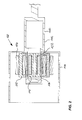
- shows a sectional view of a contactless connector system according to the present invention during the mating process;
- FIG. 2
- shows a sectional view of the contactless connector system of
FIG. 1 in the mated position; - FIG. 3
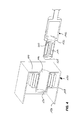
- shows a perspective view of the system of
FIG. 1 ; - FIG. 4
- shows a perspective sectional view of the system of
FIG. 1 ; - FIG. 5
- shows a sectional view of the mated connector system as shown in
FIG. 2 ; - FIG. 6
- shows another perspective view of the contactless connector system;
- FIG. 7
- shows another perspective view of the mated connector system;
- FIG. 8
- shows a second embodiment of a contactless connector according to the present invention.
- Referring now to
FIG. 1 , acontactless connector system 100 according to the present invention is explained in more detail. - A
contactless connector 102 according to the present invention has aprimary side coil 106 which is formed rotation-symmetrically around amain axis 108 of theconnector 102. Themain axis 108 is the longitudinal axis of theconnector 102 and coincides with the plug-indirection 109 between theconnector 102 and thereceptacle 104. According to the present invention, theconnector 102 is designed to be perfectly rotation-symmetric so that no fixed mating orientation with respect to an angle around themain axis 108 is required for an optimal inductive coupling. - For guiding the magnetic field that is induced by a current in the
primary side coil 106, aferromagnetic core 110 which also is rotation-symmetric with regard to theaxis 108, is provided. Thecore 110 preferably consists of a soft magnetic ferrite, as this is known to a person skilled in the art. Due to the contactless inductive transfer of electrical power, theconnector 102 can be covered completely by ahermetic overmolding 112. This complete encapsulation provides an ideal waterproof and rugged connector for use in rough environments. - The
mating receptacle 104 provided at an EV to be charged, comprises a plurality ofsecondary coils 114 which are connected inductively via theplug 102 to a power source, as this is generally known for inductive charging (not shown in the figures). As this will be apparent from the following figures, thesecondary coils 114 are arranged around arecess 116. The recess is formed to accommodate at least a part of thecontactless connector 102, in particular, the part comprising the power transmittingprimary side coil 106. Each of the secondary side coils 114 is wound onto aferrite core 118. Such ferromagnetic cores are used, as this is generally known, for guiding the magnetic field generated by theprimary side coil 106 in a proper way to couple same with the secondary side coils 114. - In the present case, each
ferromagnetic core 118 has an essentially U-shaped form, itsbasis 120 extending along themain axis 108 and its twolegs 122 being oriented towards the center of therecess 116. Thus, a particularly efficient coupling can be achieved between the secondary side coils 114 and theprimary side coil 106. Thereceptacle 104 is also formed in a way that thecoils 114 together with thecores 118 and all electric leads are encased hermetically within ahousing 124. Thehousing 124 may be formed by a molded plastic material. In particular, therecess 116 and the side wall facing towards theconnector 102 can be fabricated without any opening into which an intrusion of moisture or dust would be possible. Thus, thereceptacle 104 may be installed in harsh environments which even may contain corrosives. - According to a further advantageous embodiment of the present invention, the primary side
ferromagnetic core 110 has anaxial opening 126 for inserting at least one lead extending to thetip 128 of theconnector 102. This allows arranging additional communication means within thetip 128 for establishing a data transmission between thereceptacle 104 and theconnector 102. Such a data connection adds several advantageous features to the connecting system according to the present invention: Apart from authentication and identification, also safety features can be incorporated, such as a transmission from the load to the power supply that the charging is completed or that overload conditions have occurred. On the other hand, it may be recognized whether a load is attached or not, or whether theconnector 102 has been inserted properly. - The communication between the secondary and the primary side may be effected by means of radio frequency, wherein an antenna element or an electromagnetic waveguide is provided on the tip of the connector. The data transmission may be based on inductive or capacitive communication means inserted in the
tip 128 or, alternatively, may use optical communication. In this case a light source and/or a detector is arranged on thetip 128 of theconnector 102 and a corresponding communication element is arranged near theclosed end 130 of therecess 116. - The particular functions of the additional data communication of course depend on the location of the power source and the
plug connector 102. In private locations, such as garages, etc. it may be enough to ensure the identity of the owner for retrieving energy, whereas in public places, payment may also be effected via the additional data communication channel. -
FIG. 2 shows thecontactless connector system 100 according to the present invention in the fully mated position. By means of a respectively adjustedshoulder 132 provided at thehousing 112 of theconnector 102, the insertion depth into therecess 116 is exactly defined, thus ensuring an optimal coupling between the secondarysided coils 114 and theprimary side coil 106. Thecores coils 114 within thereceptacle 104 to a power supply and connecting thecoil 106 to a respective load. - In any case, a secure and complete galvanic separation between the secondary side and the primary side is effected by means of the
hermetic enclosures -
FIG. 3 shows thecontactless connector system 100 in a schematic perspective view. Thecontactless connector 102 is inserted into the recess of thereceptacle 104 in adirection 109 along themain axis 108. According to the present invention, the only accurate positioning that an operator has to be aware of is to insert theconnector 102 until theshoulder 132 touches thehousing 124 of the receptacle. Apart from that theconnector 102 may be rotated freely around themain axis 108, as this is indicated by thearrow 134. According to the embodiment envisaged in this drawing, theconnector 102 is connected directly to the charging circuitry of the power supply via thecable 136, whereas thereceptacle 104 is arranged somewhere at the chassis of the EV, thesecondary coils 114 being connected to the battery of the electric vehicle. -
FIG. 4 shows a sectional view of the arrangement ofFIG. 3 in order to more clearly explain the particular geometric arrangements according to the present invention. As may be seen fromFIG. 4 , therecess 116 of thereceptacle 104 has the form of a hollow cylinder closed on oneend 130. A hermetically sealedhousing 124 is integrally formed with the recess and protects thecoils 114 and all electric connections and electric circuitry which may be further contained within thehousing 124. - The
connector 102 has a taperedtip 128 for facilitating the insertion of the connector into therecess 116. The connector itself and in particular thecoil 106 and theferrite core 110 are formed with rotation-symmetry so that the angular position of the connector within therecess 116 does not matter. Ashoulder 132 limits the insertion of theplug connector 102 into therecess 116, thus ensuring an optimal alignment of thecoils -
FIG. 5 shows a sectional view of the matedcontactless connector system 100. As may be derived from this figure, a plurality ofcoils 114, here four coils, are arranged around therecess 116. Theferrite cores 118 have the form of pole pieces in order to allow a particularly uniform guiding of the magnetic field from theferromagnetic core 110 of theconnector 102, Theprimary side coil 106 is wound symmetrically around the main axis of the connector, which is oriented into the drawing plane inFIG. 5 . -
FIG. 6 and7 show perspective views of thecontactless connector system 100 in the unmated and mated position, respectively, which are rotated compared to the drawing ofFIG. 4 . In particular, the rounded form of the secondary side ferromagnetic cores which allows an optimal magnetic coupling to the core of theconnector 102 may be seen from this figure.FIG. 5 to 7 show four coils which are evenly distributed around the circumference of therecess 116. However, also other numbers ofcoils 114 may be provided, as long as the arrangement allows for a rotation-symmetric insertion of theconnector 102. - The schematic drawings of
figures 1 to 7 do not show any retention means for theconnector 102 when inserted into therecess 116.FIG. 8 , therefore, shows an example of alatch 138, which might engage with a corresponding, preferably rotation-symmetric retention means at thereceptacle 104 for securing theconnector 102 in the plugged position. As shown schematically inFIG. 8 , an RF oroptical contact 140 and a rotation-symmetric contact ring for a capacitive orRF signal transmission 142 may be provided simultaneously or alternatively for allowing an additional data communication function, as this was explained above. Releasing means 144 allow to release thelatch 138 after the charging process has been completed. - In summary, the
contactless connector system 100 according to the present invention improves the transmission efficiency for transferring energy into an EV without the necessity of a tight tolerance control. For manufacturers and designers, a maximum freedom of design is achieved. The charging process and in particular connecting a vehicle to be charged to a power source may also be automated because of the simple rotation-symmetric form of the mating components. Data transmission means additionally allow automated control and authentication before, during and after the charging process. -
Reference Numerals Description 100 contactless connector system 102 connector 104 receptacle 106 primary side coil 108 main axis 109 plug-in direction 110 ferromagnetic core 112 hermetic overmolding of the connector 114 secondary side coils 116 recess 118 ferrite core 120 basis of core 122 legs of core 124 housing of receptacle 126 axial opening 128 tip of connector 130 closed end of recess 132 shoulder 134 rotation angle 136 cable 138 latch 140 RF or optical contact 142 capacitive or RF contact ring 144 releasing means for latch
Claims (15)
- Contactless connector for coupling an electric vehicle to a power supply, said connector (102) comprising:at least one primary side coil (106) being connected to a feeding power source for being inductively coupled to at least one secondary side coil (114) being arranged at a receptacle (104), said receptacle (104) being formed to engage with the connector (102),wherein said primary side coil (106) is constructed rotation-symmetrically with respect to a rotation axis (108) of the connector (102),said rotation axis (108) coinciding with a plug-in direction of said contactless connector (102) into the receptacle (104).
- Contactless connector according to claim 1, wherein said primary side coil (106) is arranged on a primary side ferromagnetic core (110) for guiding a magnetic field induced by said at least one primary side coil (106).
- Contactless connector according to claim 2, wherein said primary side ferromagnetic core (110) is provided with an axial opening (126) for inserting at least one lead extending to a tip (128) of said connector (102).
- Contactless connector according to one of the preceding claims, further comprising a hermetically sealed housing (112) encapsulating the connector.
- Contactless connector according to one of the preceding claims, further comprising data connection means (140, 142) for contactless communication based on radio frequency, inductive, capacitive, and/or optical data transmission.
- Receptacle for a contactless connector according to one of the preceding claims, said receptacle (104) comprising at least one secondary side coil (114) and a recess (116) for accommodating the contactless connector (102).
- Receptacle according to claim 6, wherein said recess (116) has the shape of a right circular cylinder with a closed basis on one end.
- Receptacle according to claim 6 or 7, wherein a plurality of secondary coils (114) are evenly distributed around a circumference of said recess (116).
- Receptacle according to one of the claims 6 to 8, further comprising means for contactless communication with the connector (102) based on radio frequency, inductive, capacitive, and/or optical data transmission.
- Receptacle according to one of the claims 6 to 9, wherein said at least one secondary coil (114) is arranged around a secondary side ferromagnetic core (118) for guiding the magnetic field generated by said primary side coil (106).
- Receptacle according to claim 10, wherein said secondary side ferromagnetic core (118) is essentially U-shaped, a basis (120) extending along a longitudinal middle axis (108) of the recess, and its two legs (122) extending towards the longitudinal middle axis of the recess.
- Receptacle according to one of the claims 6 to 11, comprising four secondary side coils (114) arranged around the circumference of the recess (116) in a way that two coils are opposing each other.
- Receptacle according to one of the claims 6 to 12, further comprising a hermetically sealing casing (124) being integrally formed with said recess (116).
- Contactless connector system comprising a contactless connector (102) according to one of the claims 1 to 5 and a receptacle (104) according to one of the claims 6 to 13.
- Contactless connector system according to claim 14, further comprising releasable latching means (138) for securing said contactless connector (102) within said recess (116).
Priority Applications (1)
| Application Number | Priority Date | Filing Date | Title |
|---|---|---|---|
| EP12150764.4A EP2614980B1 (en) | 2012-01-11 | 2012-01-11 | Contactless connector system for coupling an electric vehicle to a power supply |
Applications Claiming Priority (1)
| Application Number | Priority Date | Filing Date | Title |
|---|---|---|---|
| EP12150764.4A EP2614980B1 (en) | 2012-01-11 | 2012-01-11 | Contactless connector system for coupling an electric vehicle to a power supply |
Publications (2)
| Publication Number | Publication Date |
|---|---|
| EP2614980A1 true EP2614980A1 (en) | 2013-07-17 |
| EP2614980B1 EP2614980B1 (en) | 2015-03-18 |
Family
ID=45507480
Family Applications (1)
| Application Number | Title | Priority Date | Filing Date |
|---|---|---|---|
| EP12150764.4A Active EP2614980B1 (en) | 2012-01-11 | 2012-01-11 | Contactless connector system for coupling an electric vehicle to a power supply |
Country Status (1)
| Country | Link |
|---|---|
| EP (1) | EP2614980B1 (en) |
Cited By (5)
| Publication number | Priority date | Publication date | Assignee | Title |
|---|---|---|---|---|
| WO2018039691A1 (en) * | 2016-08-31 | 2018-03-08 | Volkmar Schitter | Charging and shut-off device for electric vehicles |
| JP2018107867A (en) * | 2016-12-22 | 2018-07-05 | 株式会社ベルニクス | Non-contact feeding transformer disposed in rotary connection part of multiple members |
| CN113921258A (en) * | 2021-09-16 | 2022-01-11 | 浙江大学 | Connector based on hemispherical electromagnetic coupler and coil optimization method |
| US20230023129A1 (en) * | 2020-04-17 | 2023-01-26 | Institute Of Geology And Geophysics, Chinese Academy Of Sciences | Contactless connector, signal processing method and storage medium |
| WO2023186962A1 (en) * | 2022-03-29 | 2023-10-05 | Institut Polytechnique De Grenoble | Electromagnetic induction interconnector of polyphase electrical systems with each other |
Families Citing this family (2)
| Publication number | Priority date | Publication date | Assignee | Title |
|---|---|---|---|---|
| CN111320108A (en) * | 2018-12-14 | 2020-06-23 | 比亚迪股份有限公司 | Automatic charging system of fork truck |
| DE102022123991A1 (en) | 2022-09-19 | 2024-03-21 | Knorr-Bremse Systeme für Schienenfahrzeuge GmbH | Arrangement of a system component of a rail vehicle with an intelligent plug connection (smart plug) and a rail vehicle with such an arrangement |
Citations (7)
| Publication number | Priority date | Publication date | Assignee | Title |
|---|---|---|---|---|
| US5350312A (en) | 1992-12-18 | 1994-09-27 | Yazaka Corporation | Feeder connector |
| EP0878811A2 (en) * | 1997-05-15 | 1998-11-18 | SUMITOMO WIRING SYSTEMS, Ltd. | Magnetic coupling device for charging electric car |
| US6297614B2 (en) | 1999-12-02 | 2001-10-02 | Kabushiki Kaisha Toyoda Jidoshokki Seisakusho | Charging paddle |
| US6356052B2 (en) | 1999-12-06 | 2002-03-12 | Kabushiki Kaisha Toyoda Jisoshokki Seisakusho | Waterproof inductive charging paddle |
| US6373221B2 (en) | 1999-12-27 | 2002-04-16 | Kabushiki Kaisha Toyoda Jidoshokki Seisakusho | Charger coupling |
| DE102009017553A1 (en) * | 2009-04-17 | 2010-10-21 | Sew-Eurodrive Gmbh & Co. Kg | Energy storage i.e. battery, charging arrangement for electrically operable motor vehicle, has primary coil accommodated in unit, where unit includes bracket attached to housing part of unit, at which primary coil is attached |
| WO2011057755A1 (en) * | 2009-11-13 | 2011-05-19 | Sew-Eurodrive Gmbh & Co. Kg | Arrangement for connecting a vehicle |
-
2012
- 2012-01-11 EP EP12150764.4A patent/EP2614980B1/en active Active
Patent Citations (7)
| Publication number | Priority date | Publication date | Assignee | Title |
|---|---|---|---|---|
| US5350312A (en) | 1992-12-18 | 1994-09-27 | Yazaka Corporation | Feeder connector |
| EP0878811A2 (en) * | 1997-05-15 | 1998-11-18 | SUMITOMO WIRING SYSTEMS, Ltd. | Magnetic coupling device for charging electric car |
| US6297614B2 (en) | 1999-12-02 | 2001-10-02 | Kabushiki Kaisha Toyoda Jidoshokki Seisakusho | Charging paddle |
| US6356052B2 (en) | 1999-12-06 | 2002-03-12 | Kabushiki Kaisha Toyoda Jisoshokki Seisakusho | Waterproof inductive charging paddle |
| US6373221B2 (en) | 1999-12-27 | 2002-04-16 | Kabushiki Kaisha Toyoda Jidoshokki Seisakusho | Charger coupling |
| DE102009017553A1 (en) * | 2009-04-17 | 2010-10-21 | Sew-Eurodrive Gmbh & Co. Kg | Energy storage i.e. battery, charging arrangement for electrically operable motor vehicle, has primary coil accommodated in unit, where unit includes bracket attached to housing part of unit, at which primary coil is attached |
| WO2011057755A1 (en) * | 2009-11-13 | 2011-05-19 | Sew-Eurodrive Gmbh & Co. Kg | Arrangement for connecting a vehicle |
Cited By (7)
| Publication number | Priority date | Publication date | Assignee | Title |
|---|---|---|---|---|
| WO2018039691A1 (en) * | 2016-08-31 | 2018-03-08 | Volkmar Schitter | Charging and shut-off device for electric vehicles |
| JP2018107867A (en) * | 2016-12-22 | 2018-07-05 | 株式会社ベルニクス | Non-contact feeding transformer disposed in rotary connection part of multiple members |
| US20230023129A1 (en) * | 2020-04-17 | 2023-01-26 | Institute Of Geology And Geophysics, Chinese Academy Of Sciences | Contactless connector, signal processing method and storage medium |
| US11601164B2 (en) * | 2020-04-17 | 2023-03-07 | Institute Of Geology And Geophysics, Chinese Academy Of Sciences | Contactless connector, signal processing method and storage medium |
| CN113921258A (en) * | 2021-09-16 | 2022-01-11 | 浙江大学 | Connector based on hemispherical electromagnetic coupler and coil optimization method |
| WO2023186962A1 (en) * | 2022-03-29 | 2023-10-05 | Institut Polytechnique De Grenoble | Electromagnetic induction interconnector of polyphase electrical systems with each other |
| FR3134251A1 (en) * | 2022-03-29 | 2023-10-06 | Institut Polytechnique De Grenoble | Interconnector by electromagnetic induction of polyphase electrical systems between them |
Also Published As
| Publication number | Publication date |
|---|---|
| EP2614980B1 (en) | 2015-03-18 |
Similar Documents
| Publication | Publication Date | Title |
|---|---|---|
| EP2614980B1 (en) | Contactless connector system for coupling an electric vehicle to a power supply | |
| US8248025B2 (en) | Charging system capable of charging electronic device by electromagnetic induction | |
| US7588461B2 (en) | Mating connectors with a continuous EMI shield | |
| JP6407139B2 (en) | Wiring harness and wireless power transmission system | |
| US20170001529A1 (en) | Electrical connecting device and charging cable for an electric vehicle | |
| US20110227527A1 (en) | Wireless charging kit for portable electronic device | |
| KR101536888B1 (en) | Portable terminal charging apparatus attached by magnetic force | |
| JP5462850B2 (en) | Power line communication system, connector device, and power line communication device | |
| CN105048227A (en) | High voltage connector assembly | |
| EP2701284A1 (en) | Resonance-type non-contact power supply system, power-receiving-side device, and power-transmission-side device | |
| WO2013076542A1 (en) | Power supply control device | |
| KR101230877B1 (en) | Wireless charger for portable device | |
| EP2783450A1 (en) | Power supply control device | |
| JP2016157681A (en) | Battery monitoring device | |
| CN104170179A (en) | Multi-pole plug connection unit for three-phase alternating current systems | |
| EP3402006A1 (en) | Secondary lock and receptacle | |
| EP2787577A1 (en) | Power plug | |
| CN104071020A (en) | Power supply control device | |
| KR20140067346A (en) | Charging inlet apparatus for electric vehicle with fast and slow charging used | |
| CN107005499B (en) | Communication system | |
| CN116249645A (en) | Wireless charger for dual electronic equipment | |
| KR101767622B1 (en) | Exterior case of portable electronic device having circuit for contact-less charge | |
| CN104078930A (en) | Power supply control device | |
| CN112290287A (en) | Charging contact joint, pairing contact joint, charging contact system and electronic equipment | |
| CN215186097U (en) | Electronic equipment shell, electronic equipment and charging equipment |
Legal Events
| Date | Code | Title | Description |
|---|---|---|---|
| PUAI | Public reference made under article 153(3) epc to a published international application that has entered the european phase |
Free format text: ORIGINAL CODE: 0009012 |
|
| AK | Designated contracting states |
Kind code of ref document: A1 Designated state(s): AL AT BE BG CH CY CZ DE DK EE ES FI FR GB GR HR HU IE IS IT LI LT LU LV MC MK MT NL NO PL PT RO RS SE SI SK SM TR |
|
| AX | Request for extension of the european patent |
Extension state: BA ME |
|
| 17P | Request for examination filed |
Effective date: 20131128 |
|
| RBV | Designated contracting states (corrected) |
Designated state(s): AL AT BE BG CH CY CZ DE DK EE ES FI FR GB GR HR HU IE IS IT LI LT LU LV MC MK MT NL NO PL PT RO RS SE SI SK SM TR |
|
| RIC1 | Information provided on ipc code assigned before grant |
Ipc: B60L 11/18 20060101AFI20140603BHEP Ipc: H01F 38/14 20060101ALI20140603BHEP Ipc: H01R 13/52 20060101ALI20140603BHEP |
|
| GRAP | Despatch of communication of intention to grant a patent |
Free format text: ORIGINAL CODE: EPIDOSNIGR1 |
|
| INTG | Intention to grant announced |
Effective date: 20141006 |
|
| GRAS | Grant fee paid |
Free format text: ORIGINAL CODE: EPIDOSNIGR3 |
|
| GRAA | (expected) grant |
Free format text: ORIGINAL CODE: 0009210 |
|
| AK | Designated contracting states |
Kind code of ref document: B1 Designated state(s): AL AT BE BG CH CY CZ DE DK EE ES FI FR GB GR HR HU IE IS IT LI LT LU LV MC MK MT NL NO PL PT RO RS SE SI SK SM TR |
|
| REG | Reference to a national code |
Ref country code: GB Ref legal event code: FG4D |
|
| REG | Reference to a national code |
Ref country code: CH Ref legal event code: EP |
|
| REG | Reference to a national code |
Ref country code: IE Ref legal event code: FG4D |
|
| REG | Reference to a national code |
Ref country code: AT Ref legal event code: REF Ref document number: 716333 Country of ref document: AT Kind code of ref document: T Effective date: 20150415 |
|
| REG | Reference to a national code |
Ref country code: DE Ref legal event code: R096 Ref document number: 602012005900 Country of ref document: DE Effective date: 20150430 |
|
| REG | Reference to a national code |
Ref country code: NL Ref legal event code: VDEP Effective date: 20150318 |
|
| REG | Reference to a national code |
Ref country code: NL Ref legal event code: VDEP Effective date: 20150318 |
|
| PG25 | Lapsed in a contracting state [announced via postgrant information from national office to epo] |
Ref country code: FI Free format text: LAPSE BECAUSE OF FAILURE TO SUBMIT A TRANSLATION OF THE DESCRIPTION OR TO PAY THE FEE WITHIN THE PRESCRIBED TIME-LIMIT Effective date: 20150318 Ref country code: NO Free format text: LAPSE BECAUSE OF FAILURE TO SUBMIT A TRANSLATION OF THE DESCRIPTION OR TO PAY THE FEE WITHIN THE PRESCRIBED TIME-LIMIT Effective date: 20150618 Ref country code: SE Free format text: LAPSE BECAUSE OF FAILURE TO SUBMIT A TRANSLATION OF THE DESCRIPTION OR TO PAY THE FEE WITHIN THE PRESCRIBED TIME-LIMIT Effective date: 20150318 Ref country code: HR Free format text: LAPSE BECAUSE OF FAILURE TO SUBMIT A TRANSLATION OF THE DESCRIPTION OR TO PAY THE FEE WITHIN THE PRESCRIBED TIME-LIMIT Effective date: 20150318 Ref country code: LT Free format text: LAPSE BECAUSE OF FAILURE TO SUBMIT A TRANSLATION OF THE DESCRIPTION OR TO PAY THE FEE WITHIN THE PRESCRIBED TIME-LIMIT Effective date: 20150318 |
|
| REG | Reference to a national code |
Ref country code: AT Ref legal event code: MK05 Ref document number: 716333 Country of ref document: AT Kind code of ref document: T Effective date: 20150318 |
|
| REG | Reference to a national code |
Ref country code: LT Ref legal event code: MG4D |
|
| PG25 | Lapsed in a contracting state [announced via postgrant information from national office to epo] |
Ref country code: GR Free format text: LAPSE BECAUSE OF FAILURE TO SUBMIT A TRANSLATION OF THE DESCRIPTION OR TO PAY THE FEE WITHIN THE PRESCRIBED TIME-LIMIT Effective date: 20150619 Ref country code: LV Free format text: LAPSE BECAUSE OF FAILURE TO SUBMIT A TRANSLATION OF THE DESCRIPTION OR TO PAY THE FEE WITHIN THE PRESCRIBED TIME-LIMIT Effective date: 20150318 Ref country code: RS Free format text: LAPSE BECAUSE OF FAILURE TO SUBMIT A TRANSLATION OF THE DESCRIPTION OR TO PAY THE FEE WITHIN THE PRESCRIBED TIME-LIMIT Effective date: 20150318 |
|
| PG25 | Lapsed in a contracting state [announced via postgrant information from national office to epo] |
Ref country code: NL Free format text: LAPSE BECAUSE OF FAILURE TO SUBMIT A TRANSLATION OF THE DESCRIPTION OR TO PAY THE FEE WITHIN THE PRESCRIBED TIME-LIMIT Effective date: 20150318 |
|
| PG25 | Lapsed in a contracting state [announced via postgrant information from national office to epo] |
Ref country code: CZ Free format text: LAPSE BECAUSE OF FAILURE TO SUBMIT A TRANSLATION OF THE DESCRIPTION OR TO PAY THE FEE WITHIN THE PRESCRIBED TIME-LIMIT Effective date: 20150318 Ref country code: RO Free format text: LAPSE BECAUSE OF FAILURE TO SUBMIT A TRANSLATION OF THE DESCRIPTION OR TO PAY THE FEE WITHIN THE PRESCRIBED TIME-LIMIT Effective date: 20150318 Ref country code: PT Free format text: LAPSE BECAUSE OF FAILURE TO SUBMIT A TRANSLATION OF THE DESCRIPTION OR TO PAY THE FEE WITHIN THE PRESCRIBED TIME-LIMIT Effective date: 20150720 Ref country code: SK Free format text: LAPSE BECAUSE OF FAILURE TO SUBMIT A TRANSLATION OF THE DESCRIPTION OR TO PAY THE FEE WITHIN THE PRESCRIBED TIME-LIMIT Effective date: 20150318 Ref country code: ES Free format text: LAPSE BECAUSE OF FAILURE TO SUBMIT A TRANSLATION OF THE DESCRIPTION OR TO PAY THE FEE WITHIN THE PRESCRIBED TIME-LIMIT Effective date: 20150318 Ref country code: EE Free format text: LAPSE BECAUSE OF FAILURE TO SUBMIT A TRANSLATION OF THE DESCRIPTION OR TO PAY THE FEE WITHIN THE PRESCRIBED TIME-LIMIT Effective date: 20150318 |
|
| PG25 | Lapsed in a contracting state [announced via postgrant information from national office to epo] |
Ref country code: PL Free format text: LAPSE BECAUSE OF FAILURE TO SUBMIT A TRANSLATION OF THE DESCRIPTION OR TO PAY THE FEE WITHIN THE PRESCRIBED TIME-LIMIT Effective date: 20150318 Ref country code: IS Free format text: LAPSE BECAUSE OF FAILURE TO SUBMIT A TRANSLATION OF THE DESCRIPTION OR TO PAY THE FEE WITHIN THE PRESCRIBED TIME-LIMIT Effective date: 20150718 Ref country code: AT Free format text: LAPSE BECAUSE OF FAILURE TO SUBMIT A TRANSLATION OF THE DESCRIPTION OR TO PAY THE FEE WITHIN THE PRESCRIBED TIME-LIMIT Effective date: 20150318 |
|
| REG | Reference to a national code |
Ref country code: DE Ref legal event code: R097 Ref document number: 602012005900 Country of ref document: DE |
|
| PG25 | Lapsed in a contracting state [announced via postgrant information from national office to epo] |
Ref country code: IT Free format text: LAPSE BECAUSE OF FAILURE TO SUBMIT A TRANSLATION OF THE DESCRIPTION OR TO PAY THE FEE WITHIN THE PRESCRIBED TIME-LIMIT Effective date: 20150318 |
|
| PLBE | No opposition filed within time limit |
Free format text: ORIGINAL CODE: 0009261 |
|
| STAA | Information on the status of an ep patent application or granted ep patent |
Free format text: STATUS: NO OPPOSITION FILED WITHIN TIME LIMIT |
|
| REG | Reference to a national code |
Ref country code: FR Ref legal event code: PLFP Year of fee payment: 5 |
|
| PG25 | Lapsed in a contracting state [announced via postgrant information from national office to epo] |
Ref country code: DK Free format text: LAPSE BECAUSE OF FAILURE TO SUBMIT A TRANSLATION OF THE DESCRIPTION OR TO PAY THE FEE WITHIN THE PRESCRIBED TIME-LIMIT Effective date: 20150318 |
|
| 26N | No opposition filed |
Effective date: 20151221 |
|
| PG25 | Lapsed in a contracting state [announced via postgrant information from national office to epo] |
Ref country code: SI Free format text: LAPSE BECAUSE OF FAILURE TO SUBMIT A TRANSLATION OF THE DESCRIPTION OR TO PAY THE FEE WITHIN THE PRESCRIBED TIME-LIMIT Effective date: 20150318 |
|
| PG25 | Lapsed in a contracting state [announced via postgrant information from national office to epo] |
Ref country code: BE Free format text: LAPSE BECAUSE OF NON-PAYMENT OF DUE FEES Effective date: 20160131 |
|
| PG25 | Lapsed in a contracting state [announced via postgrant information from national office to epo] |
Ref country code: BE Free format text: LAPSE BECAUSE OF FAILURE TO SUBMIT A TRANSLATION OF THE DESCRIPTION OR TO PAY THE FEE WITHIN THE PRESCRIBED TIME-LIMIT Effective date: 20150318 Ref country code: LU Free format text: LAPSE BECAUSE OF FAILURE TO SUBMIT A TRANSLATION OF THE DESCRIPTION OR TO PAY THE FEE WITHIN THE PRESCRIBED TIME-LIMIT Effective date: 20160111 |
|
| REG | Reference to a national code |
Ref country code: CH Ref legal event code: PL |
|
| PG25 | Lapsed in a contracting state [announced via postgrant information from national office to epo] |
Ref country code: MC Free format text: LAPSE BECAUSE OF FAILURE TO SUBMIT A TRANSLATION OF THE DESCRIPTION OR TO PAY THE FEE WITHIN THE PRESCRIBED TIME-LIMIT Effective date: 20150318 |
|
| PG25 | Lapsed in a contracting state [announced via postgrant information from national office to epo] |
Ref country code: CH Free format text: LAPSE BECAUSE OF NON-PAYMENT OF DUE FEES Effective date: 20160131 Ref country code: LI Free format text: LAPSE BECAUSE OF NON-PAYMENT OF DUE FEES Effective date: 20160131 |
|
| REG | Reference to a national code |
Ref country code: IE Ref legal event code: MM4A |
|
| REG | Reference to a national code |
Ref country code: FR Ref legal event code: PLFP Year of fee payment: 6 |
|
| PG25 | Lapsed in a contracting state [announced via postgrant information from national office to epo] |
Ref country code: IE Free format text: LAPSE BECAUSE OF NON-PAYMENT OF DUE FEES Effective date: 20160111 |
|
| PG25 | Lapsed in a contracting state [announced via postgrant information from national office to epo] |
Ref country code: MT Free format text: LAPSE BECAUSE OF FAILURE TO SUBMIT A TRANSLATION OF THE DESCRIPTION OR TO PAY THE FEE WITHIN THE PRESCRIBED TIME-LIMIT Effective date: 20150318 |
|
| REG | Reference to a national code |
Ref country code: FR Ref legal event code: PLFP Year of fee payment: 7 |
|
| PG25 | Lapsed in a contracting state [announced via postgrant information from national office to epo] |
Ref country code: SM Free format text: LAPSE BECAUSE OF FAILURE TO SUBMIT A TRANSLATION OF THE DESCRIPTION OR TO PAY THE FEE WITHIN THE PRESCRIBED TIME-LIMIT Effective date: 20150318 Ref country code: HU Free format text: LAPSE BECAUSE OF FAILURE TO SUBMIT A TRANSLATION OF THE DESCRIPTION OR TO PAY THE FEE WITHIN THE PRESCRIBED TIME-LIMIT; INVALID AB INITIO Effective date: 20120111 Ref country code: CY Free format text: LAPSE BECAUSE OF FAILURE TO SUBMIT A TRANSLATION OF THE DESCRIPTION OR TO PAY THE FEE WITHIN THE PRESCRIBED TIME-LIMIT Effective date: 20150318 |
|
| PG25 | Lapsed in a contracting state [announced via postgrant information from national office to epo] |
Ref country code: MK Free format text: LAPSE BECAUSE OF FAILURE TO SUBMIT A TRANSLATION OF THE DESCRIPTION OR TO PAY THE FEE WITHIN THE PRESCRIBED TIME-LIMIT Effective date: 20150318 Ref country code: TR Free format text: LAPSE BECAUSE OF FAILURE TO SUBMIT A TRANSLATION OF THE DESCRIPTION OR TO PAY THE FEE WITHIN THE PRESCRIBED TIME-LIMIT Effective date: 20150318 Ref country code: MT Free format text: LAPSE BECAUSE OF FAILURE TO SUBMIT A TRANSLATION OF THE DESCRIPTION OR TO PAY THE FEE WITHIN THE PRESCRIBED TIME-LIMIT Effective date: 20160131 |
|
| PG25 | Lapsed in a contracting state [announced via postgrant information from national office to epo] |
Ref country code: BG Free format text: LAPSE BECAUSE OF FAILURE TO SUBMIT A TRANSLATION OF THE DESCRIPTION OR TO PAY THE FEE WITHIN THE PRESCRIBED TIME-LIMIT Effective date: 20150318 |
|
| PG25 | Lapsed in a contracting state [announced via postgrant information from national office to epo] |
Ref country code: AL Free format text: LAPSE BECAUSE OF FAILURE TO SUBMIT A TRANSLATION OF THE DESCRIPTION OR TO PAY THE FEE WITHIN THE PRESCRIBED TIME-LIMIT Effective date: 20150318 |
|
| REG | Reference to a national code |
Ref country code: DE Ref legal event code: R079 Ref document number: 602012005900 Country of ref document: DE Free format text: PREVIOUS MAIN CLASS: B60L0011180000 Ipc: B60L0050500000 |
|
| PGFP | Annual fee paid to national office [announced via postgrant information from national office to epo] |
Ref country code: DE Payment date: 20221130 Year of fee payment: 12 |
|
| PGFP | Annual fee paid to national office [announced via postgrant information from national office to epo] |
Ref country code: GB Payment date: 20231130 Year of fee payment: 13 |
|
| PGFP | Annual fee paid to national office [announced via postgrant information from national office to epo] |
Ref country code: FR Payment date: 20231212 Year of fee payment: 13 |