EP2623145A1 - Retractable needle apparatus - Google Patents
Retractable needle apparatus Download PDFInfo
- Publication number
- EP2623145A1 EP2623145A1 EP12000736.4A EP12000736A EP2623145A1 EP 2623145 A1 EP2623145 A1 EP 2623145A1 EP 12000736 A EP12000736 A EP 12000736A EP 2623145 A1 EP2623145 A1 EP 2623145A1
- Authority
- EP
- European Patent Office
- Prior art keywords
- syringe
- needle
- cover
- catch
- plunger
- Prior art date
- Legal status (The legal status is an assumption and is not a legal conclusion. Google has not performed a legal analysis and makes no representation as to the accuracy of the status listed.)
- Withdrawn
Links
Images


Classifications
-
- A—HUMAN NECESSITIES
- A61—MEDICAL OR VETERINARY SCIENCE; HYGIENE
- A61M—DEVICES FOR INTRODUCING MEDIA INTO, OR ONTO, THE BODY; DEVICES FOR TRANSDUCING BODY MEDIA OR FOR TAKING MEDIA FROM THE BODY; DEVICES FOR PRODUCING OR ENDING SLEEP OR STUPOR
- A61M5/00—Devices for bringing media into the body in a subcutaneous, intra-vascular or intramuscular way; Accessories therefor, e.g. filling or cleaning devices, arm-rests
- A61M5/178—Syringes
- A61M5/31—Details
- A61M5/32—Needles; Details of needles pertaining to their connection with syringe or hub; Accessories for bringing the needle into, or holding the needle on, the body; Devices for protection of needles
- A61M5/3205—Apparatus for removing or disposing of used needles or syringes, e.g. containers; Means for protection against accidental injuries from used needles
- A61M5/321—Means for protection against accidental injuries by used needles
- A61M5/322—Retractable needles, i.e. disconnected from and withdrawn into the syringe barrel by the piston
- A61M5/3232—Semi-automatic needle retraction, i.e. in which triggering of the needle retraction requires a deliberate action by the user, e.g. manual release of spring-biased retraction means
-
- A—HUMAN NECESSITIES
- A61—MEDICAL OR VETERINARY SCIENCE; HYGIENE
- A61M—DEVICES FOR INTRODUCING MEDIA INTO, OR ONTO, THE BODY; DEVICES FOR TRANSDUCING BODY MEDIA OR FOR TAKING MEDIA FROM THE BODY; DEVICES FOR PRODUCING OR ENDING SLEEP OR STUPOR
- A61M5/00—Devices for bringing media into the body in a subcutaneous, intra-vascular or intramuscular way; Accessories therefor, e.g. filling or cleaning devices, arm-rests
- A61M5/178—Syringes
- A61M5/31—Details
- A61M5/32—Needles; Details of needles pertaining to their connection with syringe or hub; Accessories for bringing the needle into, or holding the needle on, the body; Devices for protection of needles
- A61M5/3205—Apparatus for removing or disposing of used needles or syringes, e.g. containers; Means for protection against accidental injuries from used needles
- A61M5/321—Means for protection against accidental injuries by used needles
- A61M5/3243—Means for protection against accidental injuries by used needles being axially-extensible, e.g. protective sleeves coaxially slidable on the syringe barrel
- A61M5/3257—Semi-automatic sleeve extension, i.e. in which triggering of the sleeve extension requires a deliberate action by the user, e.g. manual release of spring-biased extension means
Abstract
A syringe cover (10) for providing needle retraction capabilities for a prefilled syringe, the prefilled syringe (1) including an extended needle (5) at a first distal end interconnecting a fluid cavity (6) containing a fluid to be expelled, the cover including: a chamber within the cover for receipt of the prefilled syringe; a first catch (15) for engaging a syringe lip (4) on the prefilled syringe, holding the syringe in a needle extended position; a translation (11) means for translating the needle from a needle extended position to a needle retracted position wherein the needle is substantially within the chamber; a plunger (18) for expelling fluids from a cavity within the syringe by translation towards the distal end of the syringe, the plunger including a first (20) catch release mechanism thereon; wherein upon movement of the plunger towards the distal end of the syringe, the first catch release mechanism (20) engages the first catch (15,16) to release the syringe from a needle extended position and the translation means translates the syringe to a needle retracted position.
Description
- The present invention relates to the field of retractable syringes and in particular, discloses a unique and modified form for dealing with single dose syringes.
- Many attempts have been made to provide for retractable syringe type technology when dealing with pre-filled syringes of the type traditionally provided in a glass ampoule or the like.
- One early patent is United States Patent No.
4624660 to Mijers et al which deals with a retractable needle arrangement for a glass ampoule. Other examples include United States Patent No.5624400 to Firth et al. , United States Patent No.5634909 to Schmitz . These applications are amongst many that provide for ampoule based retractable needle operation where a standard ampoule is provided and retractable needle operations are carried out around the standard ampoule. - The problem with prior art devices is that they can be cumbersome and expensive to manufacture requiring the interaction of multiple parts.
- Any discussion of the prior art throughout the specification should in no way be considered as an admission that such prior art is widely known or forms part of common general knowledge in the field.
- It is an object of the present invention to provide an improved form of retractable syringe arrangement for use with pre-filled syringes.
- In accordance with a first aspect of the present invention, there is provided a syringe cover for providing needle retraction capabilities for a prefilled syringe, the prefilled syringe including an extended needle at a first distal end interconnecting a fluid cavity containing a fluid to be expelled, the cover including: a chamber within the cover for receipt of the prefilled syringe; a first catch for engaging a syringe lip on the prefilled syringe, holding the syringe in a needle extended position; a translation means for translating the needle from a needle extended position to a needle retracted position wherein the needle is substantially within the chamber; a plunger for expelling fluids from a cavity within the syringe by translation towards the distal end of the syringe, the plunger including a first catch release mechanism thereon; wherein upon movement of the plunger towards the distal end of the syringe, the first catch release mechanism engages the first catch to release the syringe from a needle extended position and the translation means translates the syringe to a needle retracted position.
- The cover further preferably can include a second catch for holding the syringe substantially permanently in a needle retracted position after translation by the translation means. The second catch preferably can include a first tab for engaging the syringe lip in the needle retract position hindering continued translation by the translation means. The second catch preferably can include a second tab for engaging the syringe lip in the needle retracted position so as to hinder movement towards the distal end of the cover.
- Preferred forms of the present in invention will now be described with reference to the accompanying drawings in which:
-
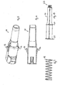
Fig. 1 illustrates a side perspective view of a pre-filled syringe without a plunger attached; -
Fig. 2 illustrates a sectional view of a pre-filled syringe without a plunger attached; -
Fig. 3 illustrates a side perspective view of the cover portions of the preferred embodiment; -
Fig. 4 illustrates a sectional view of the cover portion of the preferred embodiment; -
Fig. 5 illustrates the cover in pre-filled form; -
Fig. 6 illustrates a section view of the cover in pre-filled form; -
Fig. 7 illustrates a spring; -
Fig. 8 illustrates a plunger; -
Fig. 9 and Fig. 10 illustrate sectional views of an assembled form of the preferred embodiment; -
Fig. 11 illustrates a side perspective view of the preferred embodiment just before utilisation; -
Fig. 12 illustrates a sectional view of the preferred embodiment just before - utilisation; -
Fig. 13 is a side perspective view of the preferred embodiment showing utilisation; -
Fig. 14 is a sectional view of the preferred embodiment near the end of utilisation; -
Fig. 15 illustrates a side perspective view at the end of utilisation; -
Fig. 16 illustrates a sectional view at the end of utilisation; -
Fig. 17 illustrates the retraction mechanism of the preferred embodiment in a nearly retracted and locked state as doesFig. 18 ; and -
Fig. 19 and Fig. 20 illustrate sectional views at the end of the retraction activation process illustrating the locking of the pre-filled syringe device in a fully retracted state. - The preferred embodiment provides for retractable syringe operation for a pre- filled disposable syringe. Pre-filled disposable syringes are becoming increasingly common where expensive drugs are utilised as they minimise the drug left in the syringe after use. Also the drug is normally provided in a pre-filled syringe in a precise dose minimising dosing errors and the time required to prepare an injection. For example,
Fig. 1 illustrates a common form ofpre-filled syringe which includes abody 2 and a tip 3 which includes a cap and a needle. Thebody 2 normally includes some form oflip 4 at a distal end to the cap 3 or needle. -
Fig. 2 illustrates a sectional view along thesyringe 1 ofFig. 1 . The pre-filled syringe includes aneedle 5 in fluid communication with areservoir 6 which contains the drug to be utilised. Thereservoir 6 includes astopper 7 at one end thereof which is moveable along the reservoir. Thestopper 7 is normally profiled along aninternal surface 8 so as to receive a mating plunger. Normally, the mating plunger is screwed into thecavity 8 during the last stage of manufacture. The single use pre-filled syringe is utilised after the cap 3 has been removed. Of course, it is well known that thearrangement 1 lacks the advantages of a retractable syringe and it is to this area that the preferred embodiment is addressed. The preferred embodiment provides single use retractable syringe capabilities for thepre-filled syringe 1 ofFig. 1 minimizing the risk of a needlestick injury to the user. - Turning now to
Fig. 3 , there is illustrated the onepiece cover 10 of the preferred embodiment in a prepackaged form before the insertion of thepre-filled syringe 1.Fig. 4 illustrates a sectional view through the arrangement ofFig. 3 wherein it is noted thecover 10 is formed from one piece by injection moulding and has been fitted with a compressedinternal spring 11. Turning toFig. 3 , thecover 10 generally includes acylindrical portion 12 and finger grip 13. - In
Fig. 5 and Fig. 6 , there are illustrated views of thecover 10 before the insertion ofinternal spring 11. Thisspring 11, illustrated inFig. 7 is inserted and thetabs 15,16 activated by bending inwards so as to catch thespring 11. - In
Fig. 8 there is illustrated a side plan view of theplunger 18 which includes twoannular rings screw end 22 for mating withstopper cavity 8 of theprefilled syringe 1. -
Fig. 5 and Fig. 6 illustrate the cover as manufactured.Fig. 7 illustrates thespring 11 before utilisation.Fig. 8 illustrates theplunger 18 which includes theannular rings screw end 22. - The pre-filled syringe is inserted in the
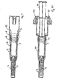
cover 10 and thetabs 15,16 are utilised to engage therim 4 of the pre-filled syringe as illustrated inFig. 9 . Thespring 11 is held under compression. Thetabs 15, 16 are depressed so as to engage therim 4 and theplunger 18 is inserted into the internal surface cavity of theplug 8 and screwed into the cavity. The arrangement ofFig. 10 can be packaged for dispatch to a site where it is to be used. The sectional axis ofFig. 9 and Fig. 10 are substantially orthogonal. - When it comes time to utilise the syringe, the cap is removed as illustrated in
Fig. 11 and Fig. 12 . Theneedle 5 is inserted into the patient and theplunger 18 depressed so that the fluid within thechamber 6 is dispensed in the usual manner. -
Figs. 13 and Fig. 14 illustrate the position as the plunger has been inserted a substantial part of its way into thecavity 6. Near the end of the plunger's stroke, theannular ring 20 engages tabs 15-16, as illustrated inFig. 14 , pushing them out past thelip 4 of thebody 2 thereby "activating" the needle retraction process.Figs. 15 and Fig. 16 illustrate the plunger substantially at the end of its stroke. Upon release of tabs 15-16, thebody 2 can move under the influence ofspring 11. Thebody 2 and attachedneedle 5 then retract within thecover 10. Thebody 2 continues to move untilrim 4 ofbody 2 engagesrim 25 of thecover 10 as illustrated inFig. 17. Fig. 18 illustrates a sectional view of another axis of the preferred embodiment. - As illustrated in
Fig. 17 , as thebody 2 moves distally, therim 4 begins to be engaged by a second set oftabs rim 4. Upon therim 4 passing, they move to engage the rim as illustrated inFig. 20 wherein thebody 2 is firmly held fixed between therim 25 and thetabs lip 4. Hence, thebody 2 is firmly held in a retracted position. The final retracted as illustrated inFig. 19 and Fig. 20 with thebody 2 firmly held in a retracted position. This aids and assists in safe disposable of the syringe after utilisation and minimises the risk of a needlestick injury to the user. - Although the invention has been described with reference to specific examples it will be appreciated by those skilled in the art that the invention may be embodied in many other forms.
- Throughout this specification and the claims which follow, unless the context requires otherwise, the word "comprise", and variations such as "comprises" and "comprising", will be understood to imply the inclusion of a stated integer or step or group of integers or steps but not the exclusion of any other integer or step or group of integers or steps.
- The reference to any prior art in this specification is not and should not be taken as an acknowledgement or any form of suggestion that the prior art forms part of the common general knowledge.
The claims defining the invention are as follows:
Claims (6)
- A syringe cover for providing needle retraction capabilities for a pre-filled syringe, the pre-filled syringe including an extended needle at a first distal end interconnecting a fluid cavity containing a fluid to be expelled, the cover including:a chamber within the cover for receipt of the pre-filled syringe;a first catch for engaging a syringe lip on the pre-filled syringe, holding the syringe in a needle extended position;a translation means for translating the needle from a needle extended position to a needle retracted position wherein the needle is substantially within said chamber;a plunger for expelling fluids from a cavity within the syringe by translation towards the distal end of the syringe, the plunger including a first catch release mechanism thereon;wherein upon movement of said plunger towards the distal end of the syringe, said first catch release mechanism engages said first catch to release the syringe from a needle extended position and said translation means translates the syringe to a needle retracted position,
- A cover as claimed in claim 1 wherein:said cover further includes a second catch for holding the syringe substantially permanently in a needle retracted position after translation by the translation means.
- A cover as claimed in claim 2 wherein said second catch includes a first tab for engaging the syringe lip in the needle retract position hindering continued translation by the translation means.
- A cover as claimed in claim 2 wherein said second catch includes a second tab for engaging the syringe lip in the needle retracted position so as to hinder movement towards the distal end of the cover.
- A syringe cover substantially as herein described with reference to any one of the embodiments of the invention illustrated in the accompanying drawings and/or examples.
- A pre-filled retractable syringe substantially as herein described with reference to any one of the embodiments of the invention illustrated in the accompanying drawings and/or examples
Priority Applications (1)
| Application Number | Priority Date | Filing Date | Title |
|---|---|---|---|
| EP12000736.4A EP2623145A1 (en) | 2012-02-03 | 2012-02-03 | Retractable needle apparatus |
Applications Claiming Priority (1)
| Application Number | Priority Date | Filing Date | Title |
|---|---|---|---|
| EP12000736.4A EP2623145A1 (en) | 2012-02-03 | 2012-02-03 | Retractable needle apparatus |
Publications (1)
| Publication Number | Publication Date |
|---|---|
| EP2623145A1 true EP2623145A1 (en) | 2013-08-07 |
Family
ID=45606953
Family Applications (1)
| Application Number | Title | Priority Date | Filing Date |
|---|---|---|---|
| EP12000736.4A Withdrawn EP2623145A1 (en) | 2012-02-03 | 2012-02-03 | Retractable needle apparatus |
Country Status (1)
| Country | Link |
|---|---|
| EP (1) | EP2623145A1 (en) |
Cited By (5)
| Publication number | Priority date | Publication date | Assignee | Title |
|---|---|---|---|---|
| US9387292B2 (en) | 2010-05-05 | 2016-07-12 | Safety Syringes, Inc. | Extended finger flange for syringe systems |
| GB2563027A (en) * | 2017-05-30 | 2018-12-05 | Janssen Pharmaceuticals Inc | Grip accessory for a manual injection device |
| USD888941S1 (en) | 2017-11-30 | 2020-06-30 | Janssen Pharmacauticals, Inc. | Grip accessory for a manual injection device |
| USD946750S1 (en) | 2018-07-11 | 2022-03-22 | Janssen Pharmaceuticals, Inc. | Grip accessory for an injection device |
| US11786665B2 (en) | 2017-05-30 | 2023-10-17 | Janssen Pharmaceuticals, Inc. | Grip accessory for a manual injection device |
Citations (8)
| Publication number | Priority date | Publication date | Assignee | Title |
|---|---|---|---|---|
| US4624660A (en) | 1984-11-02 | 1986-11-25 | Duphar International Research B.V. | Automatic injection device |
| US5624400A (en) | 1990-05-09 | 1997-04-29 | Safety Syringes, Inc. | Disposable self-shielding aspirating syringe |
| US5634909A (en) | 1993-12-09 | 1997-06-03 | Schmitz; William L. | Auto-retracting needle injector system |
| FR2830765A1 (en) * | 2001-10-15 | 2003-04-18 | Plastic Omnium Cie | Injection syringe safety device comprises protective sleeve with expanding end opening |
| FR2861598A1 (en) * | 2003-10-29 | 2005-05-06 | Plastef Investissements | Injection syringe with safety sleeve has body attached to supporting sleeve by ring with transverse connecting wall with slit(s) for retaining member |
| WO2006008086A1 (en) * | 2004-07-21 | 2006-01-26 | Sergio Restelli | Safety kit for protecting the needle of a standard syringe, a glass syringe or a carpule |
| WO2007144507A1 (en) * | 2006-06-16 | 2007-12-21 | Marc Brunel | Safety device for injecting a medicinal product, such as a lyophilized product |
| EP2047879A1 (en) * | 2007-10-11 | 2009-04-15 | Rexam Pharma La Verpillière | Safety assembly for an injection syringe |
-
2012
- 2012-02-03 EP EP12000736.4A patent/EP2623145A1/en not_active Withdrawn
Patent Citations (8)
| Publication number | Priority date | Publication date | Assignee | Title |
|---|---|---|---|---|
| US4624660A (en) | 1984-11-02 | 1986-11-25 | Duphar International Research B.V. | Automatic injection device |
| US5624400A (en) | 1990-05-09 | 1997-04-29 | Safety Syringes, Inc. | Disposable self-shielding aspirating syringe |
| US5634909A (en) | 1993-12-09 | 1997-06-03 | Schmitz; William L. | Auto-retracting needle injector system |
| FR2830765A1 (en) * | 2001-10-15 | 2003-04-18 | Plastic Omnium Cie | Injection syringe safety device comprises protective sleeve with expanding end opening |
| FR2861598A1 (en) * | 2003-10-29 | 2005-05-06 | Plastef Investissements | Injection syringe with safety sleeve has body attached to supporting sleeve by ring with transverse connecting wall with slit(s) for retaining member |
| WO2006008086A1 (en) * | 2004-07-21 | 2006-01-26 | Sergio Restelli | Safety kit for protecting the needle of a standard syringe, a glass syringe or a carpule |
| WO2007144507A1 (en) * | 2006-06-16 | 2007-12-21 | Marc Brunel | Safety device for injecting a medicinal product, such as a lyophilized product |
| EP2047879A1 (en) * | 2007-10-11 | 2009-04-15 | Rexam Pharma La Verpillière | Safety assembly for an injection syringe |
Cited By (12)
| Publication number | Priority date | Publication date | Assignee | Title |
|---|---|---|---|---|
| US9387292B2 (en) | 2010-05-05 | 2016-07-12 | Safety Syringes, Inc. | Extended finger flange for syringe systems |
| US9802000B2 (en) | 2010-05-05 | 2017-10-31 | Safety Syringes, Inc. | Extended finger flange for syringe systems |
| US10646657B2 (en) | 2010-05-05 | 2020-05-12 | Safety Syringes, Inc. | Extended finger flange for syringe systems |
| GB2563027A (en) * | 2017-05-30 | 2018-12-05 | Janssen Pharmaceuticals Inc | Grip accessory for a manual injection device |
| USD902391S1 (en) | 2017-05-30 | 2020-11-17 | Janssen Pharmaceuticals, Inc. | Grip accessory for a manual injection device |
| USD902392S1 (en) | 2017-05-30 | 2020-11-17 | Janssen Pharmaceuticals, Inc. | Grip accessory for a manual injection device |
| USD903108S1 (en) | 2017-05-30 | 2020-11-24 | Janssen Pharmaceuticals, Inc. | Grip accessory for a manual injection device |
| GB2563027B (en) * | 2017-05-30 | 2022-04-06 | Janssen Pharmaceuticals Inc | Grip accessory for a manual injection device |
| US11786665B2 (en) | 2017-05-30 | 2023-10-17 | Janssen Pharmaceuticals, Inc. | Grip accessory for a manual injection device |
| US11918791B2 (en) | 2017-05-30 | 2024-03-05 | Janssen Pharmaceuticals, Inc. | Grip accessory for a manual injection device |
| USD888941S1 (en) | 2017-11-30 | 2020-06-30 | Janssen Pharmacauticals, Inc. | Grip accessory for a manual injection device |
| USD946750S1 (en) | 2018-07-11 | 2022-03-22 | Janssen Pharmaceuticals, Inc. | Grip accessory for an injection device |
Similar Documents
| Publication | Publication Date | Title |
|---|---|---|
| JP5627645B2 (en) | Plunger for retractable syringe and retractable syringe provided with the plunger | |
| EP2968795B1 (en) | Retractable needle adapters and safety syringes | |
| EP2968063B1 (en) | Medicament container carrier and adapter | |
| US10888670B2 (en) | Integrated passive syringe needle safety system with torqued compression spring and multi-part collar | |
| WO2014124427A1 (en) | Needle assisted jet injection device having reduced trigger force | |
| EP2623145A1 (en) | Retractable needle apparatus | |
| JP6511653B2 (en) | Retainer for retractable needle assembly and syringe | |
| KR102209807B1 (en) | Cap with hemispherical part for medical injector | |
| CN106061529A (en) | Automatic injection device | |
| US20130331786A1 (en) | Device for Controlling a Penetration Depth of Injection Needle | |
| JP2016187719A (en) | Improved retractable needle for syringe | |
| CN111050825B (en) | Auxiliary injection device for selectively injecting a component contained in a medical container | |
| US11298466B2 (en) | Needle capture retractable needle safety syringes | |
| US11357925B2 (en) | Automatic injection device provided with a device for generating sound signals | |
| AU2011265487A1 (en) | Retractable needle apparatus and method | |
| US9295787B2 (en) | Adapter means for use in combination with a pre-filled syringe and a safety device, safety device and injection device | |
| US20150038913A1 (en) | Safety hypodermic syringe | |
| WO2016178600A1 (en) | Single-use carpule injection syringe | |
| US9539399B2 (en) | Safety syringe |
Legal Events
| Date | Code | Title | Description |
|---|---|---|---|
| PUAI | Public reference made under article 153(3) epc to a published international application that has entered the european phase |
Free format text: ORIGINAL CODE: 0009012 |
|
| 17P | Request for examination filed |
Effective date: 20120203 |
|
| AK | Designated contracting states |
Kind code of ref document: A1 Designated state(s): AL AT BE BG CH CY CZ DE DK EE ES FI FR GB GR HR HU IE IS IT LI LT LU LV MC MK MT NL NO PL PT RO RS SE SI SK SM TR |
|
| AX | Request for extension of the european patent |
Extension state: BA ME |
|
| STAA | Information on the status of an ep patent application or granted ep patent |
Free format text: STATUS: THE APPLICATION IS DEEMED TO BE WITHDRAWN |
|
| 18D | Application deemed to be withdrawn |
Effective date: 20140208 |