EP2642772A1 - Position information transmission device, position information transmission system and position information setting method - Google Patents
Position information transmission device, position information transmission system and position information setting method Download PDFInfo
- Publication number
- EP2642772A1 EP2642772A1 EP11841402.8A EP11841402A EP2642772A1 EP 2642772 A1 EP2642772 A1 EP 2642772A1 EP 11841402 A EP11841402 A EP 11841402A EP 2642772 A1 EP2642772 A1 EP 2642772A1
- Authority
- EP
- European Patent Office
- Prior art keywords
- position information
- transmission device
- information transmission
- data
- identification information
- Prior art date
- Legal status (The legal status is an assumption and is not a legal conclusion. Google has not performed a legal analysis and makes no representation as to the accuracy of the status listed.)
- Withdrawn
Links
Images


Classifications
-
- H—ELECTRICITY
- H04—ELECTRIC COMMUNICATION TECHNIQUE
- H04W—WIRELESS COMMUNICATION NETWORKS
- H04W4/00—Services specially adapted for wireless communication networks; Facilities therefor
- H04W4/02—Services making use of location information
-
- H—ELECTRICITY
- H04—ELECTRIC COMMUNICATION TECHNIQUE
- H04B—TRANSMISSION
- H04B1/00—Details of transmission systems, not covered by a single one of groups H04B3/00 - H04B13/00; Details of transmission systems not characterised by the medium used for transmission
- H04B1/69—Spread spectrum techniques
- H04B1/707—Spread spectrum techniques using direct sequence modulation
-
- H—ELECTRICITY
- H04—ELECTRIC COMMUNICATION TECHNIQUE
- H04W—WIRELESS COMMUNICATION NETWORKS
- H04W64/00—Locating users or terminals or network equipment for network management purposes, e.g. mobility management
-
- G—PHYSICS
- G01—MEASURING; TESTING
- G01S—RADIO DIRECTION-FINDING; RADIO NAVIGATION; DETERMINING DISTANCE OR VELOCITY BY USE OF RADIO WAVES; LOCATING OR PRESENCE-DETECTING BY USE OF THE REFLECTION OR RERADIATION OF RADIO WAVES; ANALOGOUS ARRANGEMENTS USING OTHER WAVES
- G01S19/00—Satellite radio beacon positioning systems; Determining position, velocity or attitude using signals transmitted by such systems
- G01S19/01—Satellite radio beacon positioning systems transmitting time-stamped messages, e.g. GPS [Global Positioning System], GLONASS [Global Orbiting Navigation Satellite System] or GALILEO
- G01S19/03—Cooperating elements; Interaction or communication between different cooperating elements or between cooperating elements and receivers
- G01S19/10—Cooperating elements; Interaction or communication between different cooperating elements or between cooperating elements and receivers providing dedicated supplementary positioning signals
- G01S19/11—Cooperating elements; Interaction or communication between different cooperating elements or between cooperating elements and receivers providing dedicated supplementary positioning signals wherein the cooperating elements are pseudolites or satellite radio beacon positioning system signal repeaters
-
- G—PHYSICS
- G01—MEASURING; TESTING
- G01S—RADIO DIRECTION-FINDING; RADIO NAVIGATION; DETERMINING DISTANCE OR VELOCITY BY USE OF RADIO WAVES; LOCATING OR PRESENCE-DETECTING BY USE OF THE REFLECTION OR RERADIATION OF RADIO WAVES; ANALOGOUS ARRANGEMENTS USING OTHER WAVES
- G01S19/00—Satellite radio beacon positioning systems; Determining position, velocity or attitude using signals transmitted by such systems
- G01S19/38—Determining a navigation solution using signals transmitted by a satellite radio beacon positioning system
- G01S19/39—Determining a navigation solution using signals transmitted by a satellite radio beacon positioning system the satellite radio beacon positioning system transmitting time-stamped messages, e.g. GPS [Global Positioning System], GLONASS [Global Orbiting Navigation Satellite System] or GALILEO
- G01S19/42—Determining position
- G01S19/48—Determining position by combining or switching between position solutions derived from the satellite radio beacon positioning system and position solutions derived from a further system
-
- G—PHYSICS
- G01—MEASURING; TESTING
- G01S—RADIO DIRECTION-FINDING; RADIO NAVIGATION; DETERMINING DISTANCE OR VELOCITY BY USE OF RADIO WAVES; LOCATING OR PRESENCE-DETECTING BY USE OF THE REFLECTION OR RERADIATION OF RADIO WAVES; ANALOGOUS ARRANGEMENTS USING OTHER WAVES
- G01S5/00—Position-fixing by co-ordinating two or more direction or position line determinations; Position-fixing by co-ordinating two or more distance determinations
- G01S5/02—Position-fixing by co-ordinating two or more direction or position line determinations; Position-fixing by co-ordinating two or more distance determinations using radio waves
- G01S5/0205—Details
- G01S5/0226—Transmitters
-
- H—ELECTRICITY
- H04—ELECTRIC COMMUNICATION TECHNIQUE
- H04W—WIRELESS COMMUNICATION NETWORKS
- H04W4/00—Services specially adapted for wireless communication networks; Facilities therefor
- H04W4/02—Services making use of location information
- H04W4/029—Location-based management or tracking services
-
- H—ELECTRICITY
- H04—ELECTRIC COMMUNICATION TECHNIQUE
- H04W—WIRELESS COMMUNICATION NETWORKS
- H04W4/00—Services specially adapted for wireless communication networks; Facilities therefor
- H04W4/20—Services signaling; Auxiliary data signalling, i.e. transmitting data via a non-traffic channel
-
- H—ELECTRICITY
- H04—ELECTRIC COMMUNICATION TECHNIQUE
- H04W—WIRELESS COMMUNICATION NETWORKS
- H04W88/00—Devices specially adapted for wireless communication networks, e.g. terminals, base stations or access point devices
- H04W88/18—Service support devices; Network management devices
Definitions
- the present invention relates to a position information transmission device, a position information transmission system, and a position information setting method.
- the present invention is related to a position information transmission device that transmits, by a wireless signal, position information indicating an installation position of the position information transmission device within a predetermined distance around the position information transmission device, a position information transmission system that has position information transmission devices and a control device to control the positional information assigned to the position information transmission devices, and a position information setting method that assigns position information to plural position information transmission devices.
- Japanese Patent Application Publication 2010-38850 discloses a position information setting device to assign position information of position information transmitters that compose a position information transmission system.
- the position information transmitters transmit the assigned position information within a predetermined distance around the position information transmitters. Therefore, position information receivers such as a mobile terminal can receive various services based on the received position information.
- other information can be assigned to the position information transmitters to transmit them within the predetermined distance.
- a method to specify such information from the position information setting device to the position information transmitters a method using a wireless communication such as Bluetooth (registered trademark) or wireless LAN (Local Area Network) is disclosed.
- Bluetooth registered trademark
- wireless LAN Local Area Network
- wired or wireless communication means should be separately prepared to register the position information on each of the position information transmitters.
- the position information is registered to the position information transmitters by using a portable recording medium.
- an amount of hardware and software to be installed is increased similar to the case of the wireless communication.
- processes to register various information are not realistic because the position information transmitters may be installed on a place such as a ceiling.
- monitoring performance is worse because it is difficult to quickly find the position information transmitters that are not operating normally.
- the present invention has an aim to provide a position information transmission device, a position information transmission system, and a position information setting method in order to register various information such as position information on plural position information transmission devices without requiring complicated equipments.
- a position information transmission device is a position information transmission device having a transmitting unit to transmit, by wireless, a spread spectrum signal generated based on position information indicating an installation position, the device comprising:
- the control unit controls the recording unit to record the ID of the pseudo spread code associated with the identification information if the data includes the identification information of the position information transmission device, and controls the transmitting unit to transmit the data by wireless if the data includes the identification information of another position information transmission device.
- the recording unit can record a predetermined information uniquely assigned to the position information transmission device, and when data associating the identification information with the predetermined information is input from the communication interface, the control unit controls the recording unit to record the predetermined information associated with the identification information if the data includes the identification information of the position information transmission device, and controls the transmitting unit to transmit the data by wireless if the data includes the identification information of another position information transmission device.
- the recording unit can record a name of the position information transmission device, and when data associating the identification information with the name is input from the communication interface, the control unit controls the recording unit to record the name associated with the identification information if the data includes the identification information of the position information transmission device, and controls the transmitting unit to transmit the data by wireless if the data includes the identification information of another position information transmission device.
- the communication interface has a function to receive the data separately from the external computer when receiving data exceeding a predetermined size.
- a position information transmission device is a position information transmission device having a transmitting unit to transmit, by wireless, a spread spectrum signal generated based on position information indicating an installation position, the device comprising:
- the control unit controls the recording unit to record the ID of the pseudo spread code associated with the identification information if the data includes the identification information of the position information transmission device, and controls the transmitting unit to transmit the data by wireless if the data includes the identification information of another position information transmission device.
- the recording unit can record a predetermined information uniquely assigned to the position information transmission device, and when data associating the identification information with the predetermined information is included in the spread spectrum signal received by the receiving unit, the control unit controls the recording unit to record the predetermined information associated with the identification information if the data includes the identification information of the position information transmission device, and controls the transmitting unit to transmit the data by wireless if the data includes the identification information of another position information transmission device.
- the recording unit can record a name of the position information transmission device, and when the data associating the identification information with the name is included in the spread spectrum signal received by the receiving unit, the control unit controls the recording unit to record the name associated with the identification information if the data includes the identification information of the position information transmission device, and controls the transmitting unit to transmit the data by wireless if the data includes the identification information of another position information transmission device.
- the control unit when the receiving unit receives the same spread spectrum signal in succession, the control unit does not control the transmitting unit to transmit, by wireless, the data included in the spread spectrum signal received for the second time or later even if the identification information of another position information transmission device is included in the spread spectrum signal.
- the control unit when the receiving unit receives the same spread spectrum signal more than once in a predetermined time period, the control unit does not control the transmitting unit to transmit, by wireless, the data included in the spread spectrum signal received for the second time or later even if the identification information of another position information transmission device is included in the spread spectrum signal.
- a position information transmission system comprising:
- the second position information transmission device is located in a transmitting area where the first position information transmission device can transmit the spread spectrum signal by wireless, and the first position information transmission device transmits, by wireless, the data associating the identification information with the position information as the spread spectrum signal from the first transmitting unit.
- different IDs of the pseudo spread code are assigned to the first position information transmission device and the second position information transmission device.
- another position information transmission device is located in a transmitting area where the second position information transmission device can transmit the spread spectrum signal by wireless
- the another position information transmission device has a receiving unit that receives the spread spectrum signal transmitted by wireless, and a control unit that, when data associating the identification information with the position information is included in the spread spectrum signal received by the receiving unit, controls the recording unit of the another position information transmission device to record the position information associated with the identification information if the data includes the identification information of the another position information transmission device.
- different IDs of the pseudo spread code are assigned to the second position information transmission device and the another position information transmission device.
- the first position information transmission devise further has a separate transmission means that separates the data and controls the first transmitting unit to transmit separate data sequentially when the data to be transmitted from the first transmitting unit exceeds a predetermined size
- the second position information transmission devise further has a separate receiving means that restores the original data from the plural separate data received by the second receiving unit.
- An alternative aspect of the present invention is a position information setting method for at least a first position information transmission device, a second position information transmission device and a control device to control position information of the position information transmission devices, wherein the position information is assigned from the control device to each of the position information transmission devices, the method comprising:
- the above described position information transmission device includes various aspects such as performed by being mounted on other devices or performed with other methods.
- the present invention can be realized as a control method having processes corresponding to the configuration of the position information transmission devise, a program enabling a computer to realize a function corresponding to the configuration of the position information transmission devise, or computer readable recording medium recording the program.
- the position information can be registered on plural position information transmission devices with simple equipment.
- the ID of the pseudo spread code can be registered on plural position information transmission devices with simple equipment.
- the predetermined information can be registered on plural position information transmission devices with simple equipment.
- the name of the position information transmission device can be registered on plural position information transmission devices with simple equipment.
- larger size data can be input to the position information transmission devices.
- the position information or the like can be registered efficiently.
- positional relation of each of the position information transmission devices can be adequately decided based on the transmitting areas of the position information transmission devices.
- larger size data can be transferred and received between the position information transmission devices.
- Fig. 1 is a schematic diagram showing an outline of a positioning system 100 of the present embodiment.
- the positioning system 100 can transmit a navigation message from a GPS (Global Positioning System) satellite to a mobile terminal 50 located outdoors.
- the navigation message is a predicted ephemeris of the GPS satellite transmitted by radio waves, and includes information such as orbital information necessary for calculating a position of the satellite.
- the mobile terminal 50 can identify its own position by calculating its own position based on the received navigation message.
- the positioning system 100 can transmit position information from IMES transmitters to the mobile terminal 50 located in a providing area of an IMES (Indoor Messaging System) 200, which is formed indoors or in a predetermined area.
- IMES Indoor Messaging System
- the position information is information that indicates an installation position of each of the IMES transmitters that compose the IMES.
- the mobile terminal 50 identifies its position based on the received position information.
- the mobile terminal 50 can receive various services from an information providing server (not illustrated) according to the position information by transmitting the position information calculated or identified as explained above to the information providing server.
- the navigation message transmitted from the GPS satellite and the position information transmitted from IMES transmitters 20, 30A and 30B are all spread spectrum signals modulated by a pseudo spread code using a pseudo random noise code (PRN code). Therefore, tracking of the signals and decoding of the signals are possible by using a publicly known method of cross correlation process between plural encoding patterns and the received signals (to identify the decoding pattern to be used for modulating each of the spread spectrum signals).
- PRN code pseudo random noise code
- the IMES transmitters 20, 30A and 30B are corresponding to the position information transmission device
- the IMES transmitter 20 is corresponding to the first position information transmission device
- the IMES transmitters 30A and 30B are corresponding to the second position information transmission device
- the IMES or the positioning system 100 is corresponding to the position information transmission system
- an IMES control device 10 is corresponding to the control device or the position information control device in the present embodiment.
- Fig. 2 is a configuration diagram showing an example of the IMES 200 formed in the positioning system 100.
- the IMES 200 has an IMES control device 10 and plural IMES transmitters 20, 30A, 30B, 30C, ---.
- the IMES transmitters 20, 30A, 30B, 30C, --- are placed in an area of the IMES 200 and transmit the position information that is converted to the above described spread spectrum signal within a predetermined ambient areas (transmitting areas Ar0, Ar1, Ar2 and Ar3).
- the IMES 200 is established in an area where the navigation message transmitted from the GPS satellite is difficult to arrive such as inside a building.
- the area is not limited to the inside a building.
- a similar IMES can be formed in a predetermined area of outside building, or formed between the inside and outside of a building.
- Figs. 3 and 4 are schematic diagrams showing alignment examples of the IMES transmitters 20, 30A, 30B, 30C, --- of the IMES 200.
- the IMES 200 is shown as a closed area in the figures, but, of course, the IMES 200 can be established by combining plural closed areas.
- plural IMES transmitters are placed to cover whole area of the IMES 200 by combining plural transmitting areas formed by the IMES transmitters.
- each of the IMES transmitters 20, 30A, 30B, 30C --- forms different transmitting areas Ar0, Ar1, Ar2, Ar3 ---, and whole area of the IMES 200 is covered by the transmitting areas Ar0, Ar1, Ar2, Ar3 ---. Therefore, the mobile terminal 50 in the area of the IMES 200 can receive the position information transmitted from one of the IMES transmitters.
- two of adjacent IMES transmitters are placed to be included in the transmitting area formed by each other.
- the IMES transmitter 30A is placed to be included in the transmitting area Ar1 formed by the IMES transmitter 20.
- the IMES transmitter 20 is placed to be included in the transmitting area Ar0 formed by the IMES transmitter 30A.
- Fig. 4 two of vertically adjacent IMES transmitters are placed to be included in the transmitting area formed by each other, while two of horizontally adjacent IMES transmitters are placed not to be included in the transmitting area formed by each other, in principle.
- the IMES transmitter is placed to include both left and right adjacent IMES transmitters in its transmitting area.
- whole the IMES 200 can be covered by fewer IMES transmitters than Fig. 3 .
- Fig. 3 and Fig.4 are examples. Needless to say, these examples can be combined arbitrarily, vertical direction and horizontal direction can be switched arbitrarily as for adjacent relationship, the IMES transmitters can be diagonally adjacent to one another, and various alignments are available.
- IMES 200 By using an IMES area formed as explained above, in the IMES 200, various data can be transmitted from the IMES control device 10 to all of the plural IMES transmitters.
- a configuration of the IMES transmitter will be explained with reference to Fig. 5 . Note that different configurations are used between the IMES transmitter 20 and the IMES transmitters 30A, 30B, 30C --- in the present embodiment.
- Fig. 5 is a block diagram showing a configuration of the IMES transmitter 20.
- the IMES transmitter 20 can communicate with the IMES control device 10 by a predetermined communication method, and has a control unit 21, transmitting unit 22, a non-volatile memory 23 and a data IF (Interface) 24.
- the non-volatile memory 23 is corresponding to the recording unit
- the data I/F 24 is corresponding to the communication interface or the transmission device side communication interface in the present embodiment.
- the data I/F 24 can be anything if it can communicate with the IMES control device 10 regardless of wired or wireless.
- the data I/F complied with various standards such as wired LAN, Bluetooth (registered trademark) or wireless LAN can be used.
- the control unit 21 has a program execution environment that is comprised of a CPU 21a and a RAM 21b, and controls each part of the IMES transmitter 20 by executing a program code stored in the non-volatile memory 23.
- the control means, for example, to control the data IF 24 for enabling data communication with the IMES control device 10, to read/write data from/on the non-volatile memory 23, to control the transmitting unit 22 to transmit positional signals or later described registration data Dset, and so on.
- the control unit 21 can also be formed by a circuit such as an IC chip if it can execute various controls described in the present embodiment.
- the program code executed by the control unit 21 includes an encoding pattern that is corresponding to an ID (e.g. PRN-ID) of a pseudo spread code. In other words, by executing the program code, the control unit 21 can execute encoding using the encoding pattern.
- an encoded message can be decoded using the encoding pattern.
- the encoding pattern should not necessarily be included in the program code because encoding and decoding can be executed using the encoding pattern provided from the encoding pattern generator.
- Various publicly known encoding pattern generators can be used. For example, the encoding pattern generator realized by combining two feedback shift registers can be used.
- the data I/F 24 receives data input from the IMES control device 10 and outputs the data to the control unit 21.
- the data input from the IMES control device 10 can be position information, a name of the transmitter, an ID of a pseudo spread code, and other data to be recorded in the IMES transmitters.
- the registration data Dset whose address is the IMES transmitter 20 is input from the IMES control device 10 to the control unit 21 via the data I/F 24.
- unique information of the IMES transmitter e.g. later described transmitter number
- the control unit 21 stores information included in the registration data Dset in a preliminarily determined area of the non-volatile memory 23. After the control unit 21 updates the information recorded in each area of the non-volatile memory 23, the control unit 21 outputs a positioning signal or the like based on the updated data to the transmitting unit 22.
- Fig. 6 is a schematic diagram showing a data structure of the non-volatile memory 23.
- the non-volatile memory 23 has areas 23A to 23G to store data.
- a transmitter number which is used as a number for identifying the transmitter, is stored.
- a manufacturing number which is recorded in the non-volatile memory of the transmitter when manufacturing the transmitter, can be used as the transmitter number.
- other unique information for each of the transmitters can be used, and information (e.g. hash value) generated by converting the other unique information with a predetermined method can be used.
- the transmitter number or the like is corresponding to the identification information in the present embodiment.
- the ID (PRN-ID) of the pseudo spread code, which is assigned to the IMES transmitter is stored.
- the name of the IMES transmitter is stored as a text data or the like.
- Short ID and Medium ID of the IMES standard are stored. The Short ID and the Medium ID are uniquely assigned to each IMES transmitter. In the IMES standard, they are defined as information that is uniquely operable in each IMES 200.
- the area 23D is an area to store unique information that is assigned to each of the IMES transmitters according to a unique operation of each IMES 200.
- position information to identify an installation position of the corresponding IMES transmitter is stored.
- the position information can be provided by arbitrarily combining latitude, longitude, altitude and floor number.
- information used for wireless communication except the position information is stored.
- data to define a transmit output level, an address, a name of the building, or the like can be stored.
- the program code to be executed by the control unit 21 is stored.
- the program code includes the encoding pattern that is corresponding to the ID (e.g. PRN-ID) of the pseudo spread code.
- the control unit 21 When the registration data Dset whose address is another IMES transmitter other than the corresponding IMES transmitter 20 is input from the IMES control device 10 to the control unit 21 via the data I/F 24, the control unit 21 outputs the registration data Dset to the transmitting unit 22. At that time, the control unit 21 outputs the registration data Dset to the transmitting unit 22 as a bit stream of the spread spectrum signal.
- the spread spectrum signal is data whose spectrum is spread by using the encoding pattern corresponding to the ID of the pseudo spread code recorded in the non-volatile memory 23.
- the transmitting unit 22 generates a transmission signal in which a carrier wave of a predetermined frequency is modulated using the bit stream input from the control unit 21, and then transmits the transmission signal by wireless via an antenna.
- the control unit 21 can control the transmitting unit 22 to transmit the bit stream of the positional signal or the like generated based on the position information to be transmitted to the mobile terminal 50 or based on the ID of the pseudo spread code.
- the bit stream of the positional signal or the like is received by the mobile terminal 50 to be used as the above described position information.
- Fig. 7 is a block diagram showing a configuration of IMES transmitters 30A, 30B, 30C --- (hereafter collectively referred to as IMES transmitter 30).
- the IMES transmitter 30 can receive the spread spectrum signal transmitted by other IMES transmitters.
- the IMES transmitter 30 has a control unit 31, a transmitting unit 32, a non-volatile memory 33, and a receiving unit 34.
- the non-volatile memory 33 is corresponding to the recording unit in the present embodiment.
- the control unit 31 has a program execution environment that is comprised of a CPU 31a and a RAM 31b, and controls each part of the IMES transmitter 30 by executing a program code stored in the non-volatile memory 33.
- the control means, for example, to read/write data from/on the non-volatile memory 33, to control the transmitting unit 32 to transmit the positional signal and the later described registration data Dset, to acquire the later described registration data Dset via the receiving unit 34, and so on.
- the control unit 31 can be formed by a circuit such as an IC chip if it can execute various controls that are described in the present embodiment.
- the program code executed by the control unit 31 includes an encoding pattern that is corresponding to an ID (e.g. PRN-ID) of the pseudo spread code.
- an ID e.g. PRN-ID
- the control unit 31 can execute encoding using the encoding pattern or execute decoding when an encoded message is received via the receiving unit 34.
- the encoding pattern should not necessarily be included in the program code.
- Various publicly known encoding pattern generators can be used.
- the receiving unit 34 receives the transmission signal transmitted from other IMES transmitters via an antenna, and then regenerates the bit stream of the spread spectrum signal by demodulating the carrier wave.
- the control unit 31 acquires original data by decoding the spread spectrum signal using the decoding pattern recorded in the non-volatile memory 33.
- the spread spectrum signal is decoded by using the above described cross correlation process.
- the function of the receiving unit 34 to receive the transmission signal and the function of the control unit 31 to decode the spread spectrum signal are same as the functions of the mobile terminal 50 to receive and decode the spread spectrum signal transmitted from the GPS satellite or the IMES transmitter. Therefore, these functions can be realized by using the same structure and function to be mounted on the mobile terminal 50.
- the control unit 31 stores information included in the registration data Dset in a preliminarily determined area of the non-volatile memory 33. After the control unit 31 updates the information recorded in each area of the non-volatile memory 33, the control unit 31 outputs the positioning signal or the like based on the updated data to the transmitting unit 32.
- the information recorded in the non-volatile memory 33 is same as the information recorded in the above described non-volatile memory 23.
- plural encoding patterns of the pseudo spread code to decode the spread spectrum signal are recorded in the non-volatile memory 33.
- the plural encoding patterns should not necessarily be recorded if the IMES transmitter 30 has the above described publicly known encoding pattern generator because the decoding can be executed with arbitrarily generating the encoding pattern by the encoding pattern generator.
- different ID of the pseudo spread code is assigned to non-volatile memories 23, 33 of each of the IMES transmitters (IMES transmitter 20, IMES transmitters 30A, 30B, 30C ---).
- the control unit 31 When the registration data Dset whose address is another IMES transmitter other than the corresponding IMES transmitter 30 is included in the spread spectrum signal acquired via the receiving unit 34, the control unit 31 outputs the registration data Dset to the transmitting unit 32. At that time, the control unit 31 outputs the registration data Dset to the transmitting unit 32 as a bit stream of the spread spectrum signal.
- the spread spectrum signal is data whose spectrum is spread by using the encoding pattern corresponding to the ID of the pseudo spread code recorded in the non-volatile memory 33.
- the transmitting unit 32 generates a transmission signal in which a carrier wave of a predetermined frequency is modulated using the bit stream input from the control unit 31, and then transmits the transmission signal by wireless via an antenna.
- the transmitting unit 31 can control the transmitting unit 32 to transmit the bit stream of the positional signal or the like generated based on the position information to be transmitted to the mobile terminal 50 or based on the ID of the pseudo spread code.
- the bit stream of the positional signal or the like is received by the mobile terminal 50 to be used as the above described position information.
- IMES transmitters have an internal power source or are supplied power from an external power via an AC adapter or the like.
- the IMES control device 10 has a control computer 11 and a database (DB) 12.
- the IMES control device 10 has a control unit 11a that controls whole the control computer 11, a data I/F 11b that can communicate with the data I/F 24 of the IMES transmitter 20, and an operation unit 11c that receives various operation inputs.
- the data IF 11b is corresponding to the control device side communication interface in the present embodiment.
- the transmitter number of each of the IMES transmitters is recorded associated with the position information of each of the IMES transmitters, the ID of the pseudo spread code assigned to each of the transmitters, the name of each of the transmitters, and other data to be recorded in each of the IMES transmitters.
- the control computer 11 can execute various operations such as reading, setting or changing of the data recorded in the DB 12 by operating the operation unit 11c.
- the various operations such as reading, setting or changing of the data recorded in the DB 12 may be executed from an external computer connected to the IMES control device 10 via a network (not illustrated) or the like.
- the data in the DB 12 is changed using various methods as described above, the data registered in the IMES transmitters should be changed. Therefore, in the present embodiment, when the data in the DB 12 is changed as explained above, it is regarded as a triggering event, and the later described process for registering is executed. More specifically, the triggering event can be a registration of new data to the DB 12, a change of the data registered in the DB 12, an operation input from the control computer 11 instructing to set or change the data recorded in the DB 12, a command input to the control computer instructing to set or change the IMES data, or the like. Of course, the triggering event is not limited to them. Various events can be adopted if the event indicates to register or change information to any of the IMES transmitters.
- Fig. 8 is a flow chart of a process for registering the position information on the control computer 11.
- Fig. 9 is a flow chart of a process for registering the position information on the IMES transmitter 20.
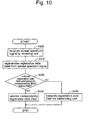
- Fig. 10 is a flow chart of a process for registering the position information on the IMES transmitter 30.
- the control computer 11 detects that and then starts a registering process for setting or changing data to the IMES transmitters (S 100).
- the following example is explained by using an example when the position information is newly registered to the IMES transmitters.
- other data can be registered to the IMES transmitters by using the same method.
- the already registered information can be changed.
- the control computer 11 at first, acquires the transmitter number of the IMES transmitter to which settings are to be made and the position information from the database (S110). Then, the control computer 11 generates the registration data Dset on which the transmitter number of the IMES transmitter is written as an address and the position information is written as a payload, and then transmits the registration data Dset to the data IF 24 of the IMES transmitter 20 via the data I/F 11b (S 120). After that, the control computer 11 finishes the process for registering.
- control unit 21 of the IMES transmitter 20 acquires the registration data Dset when it is transmitted via the data I/F 24 (S200), then judges whether or not the data is addressed to the IMES transmitter 20 by comparing the transmitter number written in the address with its own transmission number recorded in the non-volatile memory 23 (S210).
- the control unit 21 acquires the position information written in the payload and then records it in the area 23E of the non-volatile memory 23 (S220). At that time, if the position information has already recorded in the area 23E of the non-volatile memory 23, the recorded information is overwritten and deleted. If the registration of the position information is finished, the IMES transmitter 20 finishes the process of setting. By the process described above, the position information can be assigned to the IMES transmitter 20.
- the control unit 21 controls the transmitting unit 22 to transmit the registration data Dset (S230).
- the control unit 21 converts the registration data to the spread spectrum signal by using the encoding pattern corresponding to the ID of the pseudo spread code recorded in the non-volatile memory 23, and then outputs the spread spectrum signal as a data bit stream to the transmitting unit 22.
- the transmitting unit 22 converts a carrier wave to a transmit frequency and then transmits it via an antenna.
- the IMES transmitter 30A exists in the transmitting area Ar0 of the IMES transmitter 20.
- the receiving unit 34 regenerates the bit stream by demodulating the signal (S300).
- the control unit 31 regenerates the registration data Dset by decoding the spread spectrum signal included in the demodulated data bit stream (S310). Note that if the regenerated data is other than the registration data Dset, the regenerated data is deleted and the following processes will not be executed.
- control unit 31 judges whether or not the data is addressed to the IMES transmitter 30A by comparing the transmitter number written in the address with its own transmission number recorded in the non-volatile memory 33 (S320). If the address of the registration data Dset is the IMES transmitter 30A (S320: Yes), the control unit 31 acquires the position information written in the payload and then records it in the area 33E (not illustrated) of the non-volatile memory 33 (S330). At that time, if the position information has already recorded in the area 33E, the recorded information is overwritten and deleted. After the registration of the position information is finished, the IMES transmitter 30A finishes the process of setting.
- the control unit 31 controls the transmitting unit 32 to transmit the registration data Dset.
- the control unit 31 converts the registration data to the spread spectrum signal by using the encoding pattern corresponding to the ID of the pseudo spread code recorded in the non-volatile memory 33, and then outputs the spread spectrum signal as a data bit stream to the transmitting unit 32.
- the transmitting unit 32 converts the carrier wave to a transmit frequency and then transmits it via an antenna (S340).
- the IMES transmitters 20 and 30B exist in the transmitting area Ar1 of the IMES transmitter 30A.
- only the IMES transmitter 30B receives the spread spectrum signal transmitted from the IMES transmitter 30A because a receiving unit is not provided on the IMES transmitter 20.
- an endless loop may be formed because the registration data Dset relayed by an IMES transmitter can be received by the same IMES transmitter again.
- the spread spectrum signal can be transmitted from the IMES transmitter 30A to the IMES transmitter 30B, and then the spread spectrum signal transmitted from the IMES transmitter 30B can be received by the IMES transmitter 30A again. Therefore, in the present embodiment, it is preferred not to transmit the same registration data Dset more than once in succession.
- Fig. 11 is a flow chart of a process for registering the position information on the IMES transmitter 30 wherein the number of transmissions of the registration data Dset is limited.
- the IMES transmitter 30A is used as an example for explanation.
- the IMES transmitter 30A receives the signal transmitted from the IMES transmitter 20 by the receiving unit 34, and then regenerates the bit stream by demodulating the signal (S400).
- the control unit 31 regenerates the registration data Dset by decoding the spread spectrum signal included in the demodulated data bit stream (S410). Note that if the regenerated data is other than the registration data Dset, the regenerated data is deleted and the following processes will not be executed.
- the control unit 31 judges whether or not the registration data Dset acquired in the process of the steps S400 and S410 is same as the registration data received in the past (S420). Specifically, the control unit 31 generates unique information from the registration data Dset acquired in the step S410, and then compares the unique information with the unique information that is temporarily recorded in the predetermined area of the RAM 31a (S420). In the predetermined area of the RAM 31a, as described in the later described step S460, the unique information concerning the recently received registration data Dset is temporarily recorded.
- the unique information can be the registration data Dset itself, a check sum generated from the registration data Dset, a hash value generated from the registration data Dset, or the like.
- the control unit 31 deletes the received registration data Dset (S470), and the process of the steps S430 to S460 will not be executed.
- the unique information generated in the step S420 does not correspond with the unique information temporarily recorded in the predetermined area of the RAM 31a (S420: No)
- the control unit 31 judges whether or not the registration data Dset is data addressed to the IMES transmitter 30A (S430). If the address of the registration data Dset is the IMES transmitter 30A (S430: Yes), the control unit 31 acquires the position information written in the payload and then records it in the area 33E (not illustrated) of the non-volatile memory 33 (S440). If the address of the registration data Dset is other than the IMES transmitter 30A (S430: No), the control unit 31 controls the transmitting unit 32 to transmit the registration data Dset (S450).
- the explanation about the process of the steps S430 to S450 is omitted here because the process is same as the process of the steps S320 to S340 in Fig. 10 .
- the control unit 31 temporarily records the unique information generated from the transmitted registration data Dset on the predetermined area of the RAM 31b and then finishes the process for registering (S460).
- the unique information temporarily recorded in the RAM 31b is held until another unique information is overwritten.
- the unique information is held until the subsequently received registration data Dset is transmitted from the transmitting unit 32. Therefore, when the same registration data Dset is received in succession, the same registration data Dset is prevented to be redundantly transmitted more than once by using the process of judgment in the step S420.
- control unit 31 can be specified to hold the unique information recorded in the predetermined area of the RAM 31b in the step S460 of Fig. 11 for a predetermined time period.
- a single unique information is recorded when only one kind of registration data Dset is received in the predetermined time period, while plural unique information is recorded when plural kinds of different registration data Dset are received in the predetermined time period (S460).
- the predetermined time period can be time enough to finish relaying the registration data Dset in all of the IMES transmitters that compose the IMES 200, for example.
- the unique information is generated from the registration data Dset acquired in the step S410.
- the control unit 31 deletes the received registration data Dset (S470), and the process of the steps S430 to S460 will not be executed. If the unique information does not correspond with any of the unique information temporarily recorded in the predetermined area of the RAM 31a (S420: No), go to the step S430. As explained above, if the unique information recorded in the predetermined area of the RAM 31b is held for the predetermined time period, the same registration data Dset is prevented to be redundantly transmitted more than once when the same registration data Dset is received more than once in the predetermined time period by using the process for judging in the step S420.
- a separate transmission function can be provided on the control computer 11 and a separate receiving function can be provided on the IMES transmitter 20.
- the separate receiving function of the IMES transmitter 20 is provided on the data I/F 24 and the data I/F 24 is achieved by a counting function to count the number of separation.
- the separate receiving function can be provided on the control unit 21.
- the control computer 11 judges the size of the registration data Dset in the step S120. Then, if the registration data Dset exceeds a predetermined size, the number of separation is notified to the IMES transmitter 20, and then separate data is transmitted to the IMES transmitter 20 sequentially. In the IMES transmitter 20, the data I/F 24 holds the notified number of separation, increments a counter each time the separate data transmitted sequentially is received, and continues to receive the separate data until the counter of the number of separation reaches the number of separation. Then, an original data is restored by combining each of the separate data, and then the data is output to the control unit 21.
- the data I/F 24, the control unit 21, or the like to execute the separate receiving is corresponding to the separate receiving means in the present embodiment.
- information amount transmittable at a time may be limited when the IMES transmitter 20 transmits the data to the IMES transmitter 30, when IMES transmitter 30 transmits the data to another IMES transmitter 30, or when the IMES transmitter 30 transmits the data to the IMES transmitter 20 if the IMES transmitter 20 has a receiving unit. Therefore, the separate transmission function can be provided on the IMES transmitters 20 and 30 enabling to transmit the registration data Dset exceeding a size limitation, and the counting function can be provided on the IMES transmitters 20 and 30 to count the number of the separation enabling to receive the registration data separately. Note that the function above can be achieved by the receiving unit of the IMES transmitters 20 and 30 or achieved by the control unit.
- the IMES transmitter 20 of the transmitting side judges the size of the registration data Dset in the step S230. Then, if the registration data Dset exceeds a predetermined size, the number of separation is notified to the IMES transmitter 30. Then, the separate data is transmitted to the IMES transmitter 30 sequentially. The IMES transmitter 30 holds the notified number of separation. Then, the IMES transmitter 30 increments a counter of the number of separation each time the separate data transmitted sequentially is received, and continues to receive the separate data until the counter of the number of separation reaches the number of separation. Then, a restored original data is acquired by the control unit 31 by combining each of the separate data.
- the control unit or the transmitting unit in each of the IMES transmitters to execute the separate transmission is corresponding to the separate transmission means
- the control unit or the receiving unit in each of the IMES transmitters to execute the separate receiving is corresponding to the separate receiving means.
- the method to transmit or receive the separate data explained in the present embodiment is an example. Needless to say, the separate data can be transmitted or received by using other publicly known methods.
- the IMES transmitter 20 has the control unit 21, the non-volatile memory 23 to record the transmitter number of the IMES transmitter 20, the position information and the ID of the pseudo spread code, and the data I/F 24.
- the control unit 21 records the position information included in the registration data Dset on the non-volatile memory 23 if the registration data Dset includes the transmitter number of the IMES transmitter 20, while the control unit 21 controls the transmitting unit 22 to transmit the registration data Dset if the registration data Dset includes the transmitter number of other than the IMES transmitter 20.
- the position information addressed to the IMES transmitter 20 is assigned to the IMES transmitter 20 itself, while the position information addressed to another IMES transmitter is transmitted as the spread spectrum signal. Therefore, the registration data Dset can be relayed to the IMES transmitter 30 having the receiving unit 34.
- the IMES transmitter 30 has the control unit 31, the non-volatile memory 33 to record the transmitter number of the IMES transmitter 30, the position information and the ID of the pseudo spread code, and the receiving unit 34 to receive the spread spectrum signal transmitted by wireless.
- the control unit 31 records the position information associated with the transmitter number on the non-volatile memory 33 if the registration data Dset includes the transmitter number of the IMES transmitter 30, while the control unit 31 controls the transmitting unit 32 to transmit the registration data Dset by wireless if the registration data Dset includes the transmitter number of other than the IMES transmitter 30.
- the registration data Dset relayed from the IMES transmitter 20 can be received and the position information can be assigned based on the registration data Dset.
- the registration data relayed can be further relayed to other IMES transmitters.
- the receiving unit is not provided on the IMES transmitter 20 and the data IF is not provided on the IMES transmitter 30 in the above described embodiment, but, of course, the receiving unit can be provided on the IMES transmitter 20. In such a case, the configuration of hardware and software can be unified between the IMES transmitters 20 and 30 although they are differently used in the IMES 200.
- the IMES control device 10 can monitor states of the IMES transmitters 30A, 30B, 30C --- via the IMES transmitter 20. For example, if a self check or the like is executed in the IMES transmitter 30A and a check result is transmitted from the transmitting unit, the IMES transmitter 20 can receive the check result by the receiving unit.
- the address to send the check result can be arbitrarily changed according to a design of each system.
- An address for transmitting error information can be prepared to control the IMES transmitter 20 to transmit the error information to the IMES control device 10 via the data I/F 24 when the IMES transmitter 20 receives the error information transmitted to the address. A flag indicating the error information can be also used.
- the information transmitted from each of the IMES transmitters is not limited to the check result. Status information of each IMES transmitter, information about other malfunctions or various information can be transmitted. Needless to say, the IMES transmitter 20 also can transmit the same information to the IMES control device 10 via the data I/F 24. In any case, performance for monitoring each of the IMES transmitters is improved.
- plural IMES transmitters 20 can be placed in one IMES 200.
- plural IMES transmitters are connected to the control computer 11.
- setting and updating the data of whole the IMES 200 can be finished more quickly because the relay of the registration data Dset is started from more than one place.
- an effect of reducing time increases if plural IMES transmitters are placed apart from each other in the IMES 200.
- the registration data Dset can be configured to include plural sets of addresses and position information, of course.
- the IMES transmitter 20 can simultaneously transmit the plural sets of the addresses and position information included in the registration data Dset from the transmitting unit 22, or can sequentially transmit each set of the address and the position information.
- the IMES transmitter 20 judges each of the addresses, acquires the position information addressed to its own transmitter number, stores the position information in the predetermined area of the non-volatile memory 23, and then executes relay transmission from the transmitting unit 22.
- the IMES transmitter 30 receives the same registration data Dset via the receiving unit 34, the IMES transmitter 30 executes same judgment, storage, relay transmission or other processes and actions as the IMES transmitter 20.
- the IMES transmitter 20 If the IMES transmitter 20 receives such a registration data Dset, the IMES transmitter 20 operates as follows.
- the IMES transmitter 20 acquires the plural kinds of information associated with the address, stores the respective information in the corresponding area of the non-volatile memory 23, and the relay transmission of the registration data Dset is not executed.
- the relay transmission of the registration data Dset is executed from the transmitting unit 22 to other IMES transmitters.
- the IMES transmitter 20 acquires the plural kinds of information associated with its own address, stores the respective information in the corresponding area of the non-volatile memory 23, and then the relay transmission of the registration data Dset is executed.
- its own transmitter number is not included in the addresses of the registration data Dset, the information are not acquired and stored, and the relay transmission of the registration data Dset is executed from the transmitting unit 22 to other IMES transmitters.
- the IMES transmitter 30 executes same judgment, storage, relay transmission or other processes and actions as the IMES transmitter 20.
- IMES control device 11: control computer, 11a: control unit, 11b: data I/F, 11c: operation unit, 12: database (DB), 20: IMES transmitter, 21: control unit, 21a: CPU, 21b: RAM, 22: transmitting unit, 23: non-volatile memory, 23A to 23E: areas, 24: data I/F, 30: IMES transmitter, 30A to 30C: IMES transmitters, 31: control unit, 32: transmitting unit, 33: non-volatile memory, 34: receiving unit, 50: mobile terminal, 100: positioning system, 200: IMES, Ar0 to Ar3: transmitting areas, Dset: registration data
Landscapes
- Engineering & Computer Science (AREA)
- Radar, Positioning & Navigation (AREA)
- Remote Sensing (AREA)
- Computer Networks & Wireless Communication (AREA)
- Signal Processing (AREA)
- Physics & Mathematics (AREA)
- General Physics & Mathematics (AREA)
- Mobile Radio Communication Systems (AREA)
Abstract
Description
- The present invention relates to a position information transmission device, a position information transmission system, and a position information setting method. In particular, the present invention is related to a position information transmission device that transmits, by a wireless signal, position information indicating an installation position of the position information transmission device within a predetermined distance around the position information transmission device, a position information transmission system that has position information transmission devices and a control device to control the positional information assigned to the position information transmission devices, and a position information setting method that assigns position information to plural position information transmission devices.
- Japanese Patent Application Publication
2010-38850 2007-278756 2009-085928 -
- [Patent Document 1] Japanese Patent Application Publication
2010-38850 - [Patent Document 2] Japanese Patent Application Publication
2007-278756 - [Patent Document 3] Japanese Patent Application Publication
2009-085928 - In the above described technologies, wired or wireless communication means should be separately prepared to register the position information on each of the position information transmitters.
- However, if a method using a wired connection to register the position information on each of the position information transmitters is adopted, it is difficult to install the position information transmitters on the existing physical environment because many wires are needed, and that can be a reason to avoid installing the position information transmission system. In addition, an amount of hardware and software to be installed is increased because a wired I/F should be prepared on each of the position information transmitters.
- Alternatively, if a method using a wireless communication to register the position information on each of the position information transmitters is adopted, an amount of hardware and software to be installed is increased depending on the configuration of wireless I/F because a means for communicating via the wireless network should be prepared on each of the position information transmitters.
- Alternatively, it can be also assumed that the position information is registered to the position information transmitters by using a portable recording medium. However, an amount of hardware and software to be installed is increased similar to the case of the wireless communication. In addition, processes to register various information are not realistic because the position information transmitters may be installed on a place such as a ceiling. Furthermore, monitoring performance is worse because it is difficult to quickly find the position information transmitters that are not operating normally.
- After considering the above, the present invention has an aim to provide a position information transmission device, a position information transmission system, and a position information setting method in order to register various information such as position information on plural position information transmission devices without requiring complicated equipments.
- A position information transmission device according to one aspect of the present invention is a position information transmission device having a transmitting unit to transmit, by wireless, a spread spectrum signal generated based on position information indicating an installation position, the device comprising:
- a recording unit that records a unique identification information of the position information transmission device, the position information, and an ID of a pseudo spread code for spreading a spectrum of the position information,
- a communication interface for communicating with an external computer, and
- a control unit that, when data associating the identification information with the position information is input from the communication interface, controls the recording unit to record the position information associated with the identification information if the data includes the identification information of the position information transmission device, and controls the transmitting unit to transmit the data by wireless if the data includes the identification information of another position information transmission device.
- In an alternative aspect of the present invention, when data associating the identification information with the ID of the pseudo spread code is input from the communication interface, the control unit controls the recording unit to record the ID of the pseudo spread code associated with the identification information if the data includes the identification information of the position information transmission device, and controls the transmitting unit to transmit the data by wireless if the data includes the identification information of another position information transmission device.
- In an alternative aspect of the present invention, the recording unit can record a predetermined information uniquely assigned to the position information transmission device, and
when data associating the identification information with the predetermined information is input from the communication interface, the control unit controls the recording unit to record the predetermined information associated with the identification information if the data includes the identification information of the position information transmission device, and controls the transmitting unit to transmit the data by wireless if the data includes the identification information of another position information transmission device. - In an alternative aspect of the present invention, the recording unit can record a name of the position information transmission device, and
when data associating the identification information with the name is input from the communication interface, the control unit controls the recording unit to record the name associated with the identification information if the data includes the identification information of the position information transmission device, and controls the transmitting unit to transmit the data by wireless if the data includes the identification information of another position information transmission device. - In an alternative aspect of the present invention, the communication interface has a function to receive the data separately from the external computer when receiving data exceeding a predetermined size.
- A position information transmission device according to another aspect of the present invention is a position information transmission device having a transmitting unit to transmit, by wireless, a spread spectrum signal generated based on position information indicating an installation position, the device comprising:
- a recording unit that records a unique identification information of the position information transmission device, the position information, and an ID of a pseudo spread code for spreading a spectrum of the position information,
- a receiving unit that receives the spread spectrum signal transmitted by wireless, and
- a control unit that, when data associating the identification information with the position information is included in the spread spectrum signal received by the receiving unit, controls the recording unit to record the position information associated with the identification information if the data includes the identification information of the position information transmission device, and controls the transmitting unit to transmit the data by wireless if the data includes the identification information of another position information transmission device.
- In an alternative aspect of the present invention, when data associating the identification information with the ID of the pseudo spread code is included in the spread spectrum signal received by the receiving unit, the control unit controls the recording unit to record the ID of the pseudo spread code associated with the identification information if the data includes the identification information of the position information transmission device, and controls the transmitting unit to transmit the data by wireless if the data includes the identification information of another position information transmission device.
- In an alternative aspect of the present invention, the recording unit can record a predetermined information uniquely assigned to the position information transmission device, and
when data associating the identification information with the predetermined information is included in the spread spectrum signal received by the receiving unit, the control unit controls the recording unit to record the predetermined information associated with the identification information if the data includes the identification information of the position information transmission device, and controls the transmitting unit to transmit the data by wireless if the data includes the identification information of another position information transmission device. - In an alternative aspect of the present invention, the recording unit can record a name of the position information transmission device, and
when the data associating the identification information with the name is included in the spread spectrum signal received by the receiving unit, the control unit controls the recording unit to record the name associated with the identification information if the data includes the identification information of the position information transmission device, and controls the transmitting unit to transmit the data by wireless if the data includes the identification information of another position information transmission device. - In an alternative aspect of the present invention, when the receiving unit receives the same spread spectrum signal in succession, the control unit does not control the transmitting unit to transmit, by wireless, the data included in the spread spectrum signal received for the second time or later even if the identification information of another position information transmission device is included in the spread spectrum signal.
- In an alternative aspect of the present invention, when the receiving unit receives the same spread spectrum signal more than once in a predetermined time period, the control unit does not control the transmitting unit to transmit, by wireless, the data included in the spread spectrum signal received for the second time or later even if the identification information of another position information transmission device is included in the spread spectrum signal.
- In an alternative aspect of the present invention, a position information transmission system, comprising:
- a fist position information transmission device that has a first transmitting unit to transmit, by wireless, a spread spectrum signal generated based on position information indicating an installation position,
- a second position information transmission device that has a second transmitting unit to transmit, by wireless, the spread spectrum signal generated based on the position information indicating the installation position, and
- a control device that controls the positional information of the position information transmission devices, wherein
- the control device has
- a control device side communication interface to be connected to the first position information transmission device and
- a means to transmit data associating unique identification information of each of the position information transmission devices with the position information to the first position information transmission device via the communication interface,
- the first position information transmission device has
- a first recording unit that records the unique identification information of the first position information transmission device, the position information, and an ID of a pseudo spread code for spreading the spectrum of the position information,
- a transmission device side communication interface for communicating with the control device, and
- a first control unit that, when data associating the identification information with the position information is input from the transmission device side communication interface, controls the first recording unit to record the position information associated with the identification information if the data includes the identification information of the first position information transmission device, and controls the first transmitting unit to transmit the data by wireless if the data includes the identification information of other than the first position information transmission device.
- the second position information transmission device has
- a second recording unit that records the unique identification information of the second position information transmission device, the position information, and the ID of the pseudo spread code for spreading the spectrum of the position information,
- a second receiving unit that receives the spread spectrum signal transmitted by wireless, and
- a second control unit that, when data associating the identification information with the position information is included in the spread spectrum signal received by the second receiving unit, controls the second recording unit to record the position information associated with the identification information if the data includes the identification information of the second position information transmission device, and controls the second transmitting unit to transmit the data by wireless if the data includes the identification information of other than the second position information transmission device. Note that ordinal numbers such as "first" and "second" are added in order to distinguish one element having a certain name from another element having the same name.
- In an alternative aspect of the present invention, the second position information transmission device is located in a transmitting area where the first position information transmission device can transmit the spread spectrum signal by wireless, and the first position information transmission device transmits, by wireless, the data associating the identification information with the position information as the spread spectrum signal from the first transmitting unit.
- In an alternative aspect of the present invention, different IDs of the pseudo spread code are assigned to the first position information transmission device and the second position information transmission device.
- In an alternative aspect of the present invention, another position information transmission device is located in a transmitting area where the second position information transmission device can transmit the spread spectrum signal by wireless, and the another position information transmission device has
a receiving unit that receives the spread spectrum signal transmitted by wireless, and
a control unit that, when data associating the identification information with the position information is included in the spread spectrum signal received by the receiving unit, controls the recording unit of the another position information transmission device to record the position information associated with the identification information if the data includes the identification information of the another position information transmission device. - In an alternative aspect of the present invention, different IDs of the pseudo spread code are assigned to the second position information transmission device and the another position information transmission device.
- In an alternative aspect of the present invention, the first position information transmission devise further has a separate transmission means that separates the data and controls the first transmitting unit to transmit separate data sequentially when the data to be transmitted from the first transmitting unit exceeds a predetermined size, and the second position information transmission devise further has a separate receiving means that restores the original data from the plural separate data received by the second receiving unit.
- An alternative aspect of the present invention is a position information setting method for at least a first position information transmission device, a second position information transmission device and a control device to control position information of the position information transmission devices, wherein
the position information is assigned from the control device to each of the position information transmission devices, the method comprising: - a data input step in which data associating identification information with the position information is input from the control device to the first position information transmission device via a predetermined communication interface,
- a first setting step in which the position information associated with the identification information is assigned to the first position information transmission device if the identification information included in the data input to the first position information transmission device is unique identification information for the first position information transmission device,
- a first transmitting step in which the first position information transmission device converts the data to a spread spectrum signal and transmits the spread spectrum signal by wireless if the data input to the first position information transmission device includes identification information of other than the first position information transmission device,
- a second setting step in which the position information associated with the identification information is assigned to the second position information transmission device if the data included in the spread spectrum signal received by the second position information transmission device includes unique identification information for the second position information transmission device,
- a second transmitting step in which the second position information transmission device converts the data to a spread spectrum signal and transmits the spread spectrum signal by wireless if the data included in the spread spectrum signal received by the second position information transmission device includes identification information of other than the second position information transmission device.
- Note that the above described position information transmission device includes various aspects such as performed by being mounted on other devices or performed with other methods. In addition, the present invention can be realized as a control method having processes corresponding to the configuration of the position information transmission devise, a program enabling a computer to realize a function corresponding to the configuration of the position information transmission devise, or computer readable recording medium recording the program.
- As explained above, by using the present invention, the position information can be registered on plural position information transmission devices with simple equipment.
In the alternative second and seventh aspects, the ID of the pseudo spread code can be registered on plural position information transmission devices with simple equipment.
In the alternative third and eighth aspects, the predetermined information can be registered on plural position information transmission devices with simple equipment.
In the alternative fourth and ninth aspects, the name of the position information transmission device can be registered on plural position information transmission devices with simple equipment.
In the alternative fifth aspect, larger size data can be input to the position information transmission devices.
In the alternative tenth and eleventh aspects, the position information or the like can be registered efficiently.
In the alternative thirteenth to sixteenth aspects, positional relation of each of the position information transmission devices can be adequately decided based on the transmitting areas of the position information transmission devices.
In the alternative seventeenth aspect, larger size data can be transferred and received between the position information transmission devices. -
-
Fig. 1 is a schematic diagram showing an outline of apositioning system 100. -
Fig. 2 is a configuration diagram showing an example of anIMES 200. -
Fig. 3 is a schematic diagram showing an alignment example of IMES transmitters of theIMES 200. -
Fig. 4 is a schematic diagram showing another alignment example of IMES transmitters of theIMES 200. -
Fig. 5 is a block diagram showing a configuration of anIMES transmitter 20. -
Fig. 6 is a schematic diagram showing a data structure of anon-volatile memory 23. -
Fig. 7 is a block diagram showing a configuration of anIMES transmitter 30. -
Fig. 8 is a flow chart of a process for registering position information on acontrol computer 11. -
Fig. 9 is a flow chart of a process for registering position information on theIMES transmitter 20. -
Fig. 10 is a flow chart of a process for registering position information on theIMES transmitter 30. -
Fig. 11 is a flow chart of a process for registering position information on theIMES transmitter 30 wherein the number of transmissions of a registration data Dset is limited. - Hereafter, embodiments of the present invention will be explained in the following order.
- (1) Configuration of a positioning system:
- (2) Process for registering data:
- (3) General overview and variation examples:
-
Fig. 1 is a schematic diagram showing an outline of apositioning system 100 of the present embodiment. Thepositioning system 100 can transmit a navigation message from a GPS (Global Positioning System) satellite to amobile terminal 50 located outdoors. The navigation message is a predicted ephemeris of the GPS satellite transmitted by radio waves, and includes information such as orbital information necessary for calculating a position of the satellite. Themobile terminal 50 can identify its own position by calculating its own position based on the received navigation message. In addition, thepositioning system 100 can transmit position information from IMES transmitters to themobile terminal 50 located in a providing area of an IMES (Indoor Messaging System) 200, which is formed indoors or in a predetermined area. The position information is information that indicates an installation position of each of the IMES transmitters that compose the IMES. Themobile terminal 50 identifies its position based on the received position information.
Themobile terminal 50 can receive various services from an information providing server (not illustrated) according to the position information by transmitting the position information calculated or identified as explained above to the information providing server. - The navigation message transmitted from the GPS satellite and the position information transmitted from
IMES transmitters - Note that the
IMES transmitters Figs. 2 ,3 ,4 , etc.) are corresponding to the position information transmission device, theIMES transmitter 20 is corresponding to the first position information transmission device, theIMES transmitters Figs. 2 ,3 ,4 , etc.) are corresponding to the second position information transmission device, the IMES or thepositioning system 100 is corresponding to the position information transmission system, and anIMES control device 10 is corresponding to the control device or the position information control device in the present embodiment. -
Fig. 2 is a configuration diagram showing an example of theIMES 200 formed in thepositioning system 100. As shown in the figure, theIMES 200 has anIMES control device 10 andplural IMES transmitters IMES transmitters IMES 200 and transmit the position information that is converted to the above described spread spectrum signal within a predetermined ambient areas (transmitting areas Ar0, Ar1, Ar2 and Ar3). - In general, the
IMES 200 is established in an area where the navigation message transmitted from the GPS satellite is difficult to arrive such as inside a building. Of course, the area is not limited to the inside a building. A similar IMES can be formed in a predetermined area of outside building, or formed between the inside and outside of a building.Figs. 3 and4 are schematic diagrams showing alignment examples of theIMES transmitters IMES 200. Although theIMES 200 is shown as a closed area in the figures, but, of course, theIMES 200 can be established by combining plural closed areas. - As shown in
Fig. 3 andFig. 4 , plural IMES transmitters are placed to cover whole area of theIMES 200 by combining plural transmitting areas formed by the IMES transmitters. For example, inFig. 3 andFig. 4 , each of theIMES transmitters IMES 200 is covered by the transmitting areas Ar0, Ar1, Ar2, Ar3 ---. Therefore, themobile terminal 50 in the area of theIMES 200 can receive the position information transmitted from one of the IMES transmitters. - Also, in the example shown in
Fig. 3 , two of adjacent IMES transmitters are placed to be included in the transmitting area formed by each other. For example, theIMES transmitter 30A is placed to be included in the transmitting area Ar1 formed by theIMES transmitter 20. On the other hand, theIMES transmitter 20 is placed to be included in the transmitting area Ar0 formed by theIMES transmitter 30A. - Also, in the example shown in
Fig. 4 , two of vertically adjacent IMES transmitters are placed to be included in the transmitting area formed by each other, while two of horizontally adjacent IMES transmitters are placed not to be included in the transmitting area formed by each other, in principle. However, in at least one of the vertically aligned plural IMES transmitters, the IMES transmitter is placed to include both left and right adjacent IMES transmitters in its transmitting area. By using the alignment above, whole theIMES 200 can be covered by fewer IMES transmitters thanFig. 3 . Of course,Fig. 3 andFig.4 are examples. Needless to say, these examples can be combined arbitrarily, vertical direction and horizontal direction can be switched arbitrarily as for adjacent relationship, the IMES transmitters can be diagonally adjacent to one another, and various alignments are available. - By using an IMES area formed as explained above, in the
IMES 200, various data can be transmitted from theIMES control device 10 to all of the plural IMES transmitters.
Here, a configuration of the IMES transmitter will be explained with reference toFig. 5 . Note that different configurations are used between theIMES transmitter 20 and theIMES transmitters -
Fig. 5 is a block diagram showing a configuration of theIMES transmitter 20. As shown in the figure, theIMES transmitter 20 can communicate with theIMES control device 10 by a predetermined communication method, and has acontrol unit 21, transmittingunit 22, anon-volatile memory 23 and a data IF (Interface) 24. Note that thenon-volatile memory 23 is corresponding to the recording unit, the data I/F 24 is corresponding to the communication interface or the transmission device side communication interface in the present embodiment. The data I/F 24 can be anything if it can communicate with theIMES control device 10 regardless of wired or wireless. For example, the data I/F complied with various standards such as wired LAN, Bluetooth (registered trademark) or wireless LAN can be used. - The
control unit 21 has a program execution environment that is comprised of aCPU 21a and aRAM 21b, and controls each part of theIMES transmitter 20 by executing a program code stored in thenon-volatile memory 23. The control here means, for example, to control the data IF 24 for enabling data communication with theIMES control device 10, to read/write data from/on thenon-volatile memory 23, to control the transmittingunit 22 to transmit positional signals or later described registration data Dset, and so on. Note that thecontrol unit 21 can also be formed by a circuit such as an IC chip if it can execute various controls described in the present embodiment. - The program code executed by the
control unit 21 includes an encoding pattern that is corresponding to an ID (e.g. PRN-ID) of a pseudo spread code. In other words, by executing the program code, thecontrol unit 21 can execute encoding using the encoding pattern. In addition, when theIMES transmitter 20 has a receiving unit as described later in the variation example, an encoded message can be decoded using the encoding pattern. Note that, when theIMES transmitter 20 has an encoding pattern generator, the encoding pattern should not necessarily be included in the program code because encoding and decoding can be executed using the encoding pattern provided from the encoding pattern generator. Various publicly known encoding pattern generators can be used. For example, the encoding pattern generator realized by combining two feedback shift registers can be used. - The data I/
F 24 receives data input from theIMES control device 10 and outputs the data to thecontrol unit 21. The data input from theIMES control device 10 can be position information, a name of the transmitter, an ID of a pseudo spread code, and other data to be recorded in the IMES transmitters. - The registration data Dset whose address is the
IMES transmitter 20 is input from theIMES control device 10 to thecontrol unit 21 via the data I/F 24. As for a format of the registration data Dset, unique information of the IMES transmitter (e.g. later described transmitter number) can be specified as an address, and the position information, the name of the transmitter, the ID of the pseudo spread code, and other data to be recorded in the IMES transmitters can be specified as a payload, for example. When the registration data Dset is input to thecontrol unit 21, thecontrol unit 21 stores information included in the registration data Dset in a preliminarily determined area of thenon-volatile memory 23. After thecontrol unit 21 updates the information recorded in each area of thenon-volatile memory 23, thecontrol unit 21 outputs a positioning signal or the like based on the updated data to the transmittingunit 22. -
Fig. 6 is a schematic diagram showing a data structure of thenon-volatile memory 23. Thenon-volatile memory 23 hasareas 23A to 23G to store data.
In thearea 23A, a transmitter number, which is used as a number for identifying the transmitter, is stored. A manufacturing number, which is recorded in the non-volatile memory of the transmitter when manufacturing the transmitter, can be used as the transmitter number. Of course, other unique information for each of the transmitters can be used, and information (e.g. hash value) generated by converting the other unique information with a predetermined method can be used. Note that the transmitter number or the like is corresponding to the identification information in the present embodiment.
In thearea 23B, the ID (PRN-ID) of the pseudo spread code, which is assigned to the IMES transmitter, is stored.
In thearea 23C, the name of the IMES transmitter is stored as a text data or the like.
In thearea 23D, Short ID and Medium ID of the IMES standard are stored. The Short ID and the Medium ID are uniquely assigned to each IMES transmitter. In the IMES standard, they are defined as information that is uniquely operable in eachIMES 200. In other words, thearea 23D is an area to store unique information that is assigned to each of the IMES transmitters according to a unique operation of eachIMES 200.
In thearea 23E, position information to identify an installation position of the corresponding IMES transmitter is stored. For example, the position information can be provided by arbitrarily combining latitude, longitude, altitude and floor number.
In thearea 23F, information used for wireless communication except the position information is stored. For example, data to define a transmit output level, an address, a name of the building, or the like can be stored.
In thearea 23G, the program code to be executed by thecontrol unit 21 is stored. As described above, the program code includes the encoding pattern that is corresponding to the ID (e.g. PRN-ID) of the pseudo spread code. - When the registration data Dset whose address is another IMES transmitter other than the
corresponding IMES transmitter 20 is input from theIMES control device 10 to thecontrol unit 21 via the data I/F 24, thecontrol unit 21 outputs the registration data Dset to the transmittingunit 22. At that time, thecontrol unit 21 outputs the registration data Dset to the transmittingunit 22 as a bit stream of the spread spectrum signal. The spread spectrum signal is data whose spectrum is spread by using the encoding pattern corresponding to the ID of the pseudo spread code recorded in thenon-volatile memory 23. - The transmitting
unit 22 generates a transmission signal in which a carrier wave of a predetermined frequency is modulated using the bit stream input from thecontrol unit 21, and then transmits the transmission signal by wireless via an antenna. Note that, without limited to the bit stream based on the registration data Dset, thecontrol unit 21 can control the transmittingunit 22 to transmit the bit stream of the positional signal or the like generated based on the position information to be transmitted to themobile terminal 50 or based on the ID of the pseudo spread code. The bit stream of the positional signal or the like is received by themobile terminal 50 to be used as the above described position information. -
Fig. 7 is a block diagram showing a configuration ofIMES transmitters IMES transmitter 30 can receive the spread spectrum signal transmitted by other IMES transmitters. As shown in the figure, theIMES transmitter 30 has acontrol unit 31, a transmittingunit 32, anon-volatile memory 33, and a receivingunit 34. Note that thenon-volatile memory 33 is corresponding to the recording unit in the present embodiment. - The
control unit 31 has a program execution environment that is comprised of aCPU 31a and aRAM 31b, and controls each part of theIMES transmitter 30 by executing a program code stored in thenon-volatile memory 33. The control here means, for example, to read/write data from/on thenon-volatile memory 33, to control the transmittingunit 32 to transmit the positional signal and the later described registration data Dset, to acquire the later described registration data Dset via the receivingunit 34, and so on. Note that thecontrol unit 31 can be formed by a circuit such as an IC chip if it can execute various controls that are described in the present embodiment. - The program code executed by the
control unit 31 includes an encoding pattern that is corresponding to an ID (e.g. PRN-ID) of the pseudo spread code. In other words, by executing the program code, thecontrol unit 31 can execute encoding using the encoding pattern or execute decoding when an encoded message is received via the receivingunit 34. Note that, when theIMES transmitter 30 has an encoding pattern generator, the encoding pattern should not necessarily be included in the program code. Various publicly known encoding pattern generators can be used. - The receiving
unit 34 receives the transmission signal transmitted from other IMES transmitters via an antenna, and then regenerates the bit stream of the spread spectrum signal by demodulating the carrier wave. Thecontrol unit 31 acquires original data by decoding the spread spectrum signal using the decoding pattern recorded in thenon-volatile memory 33. The spread spectrum signal is decoded by using the above described cross correlation process. As explained above, the function of the receivingunit 34 to receive the transmission signal and the function of thecontrol unit 31 to decode the spread spectrum signal are same as the functions of themobile terminal 50 to receive and decode the spread spectrum signal transmitted from the GPS satellite or the IMES transmitter. Therefore, these functions can be realized by using the same structure and function to be mounted on themobile terminal 50. - When the spread spectrum signal acquired via the receiving
unit 34 includes the registration data Dset whose address is theIMES transmitter 30, thecontrol unit 31 stores information included in the registration data Dset in a preliminarily determined area of thenon-volatile memory 33. After thecontrol unit 31 updates the information recorded in each area of thenon-volatile memory 33, thecontrol unit 31 outputs the positioning signal or the like based on the updated data to the transmittingunit 32. - The information recorded in the
non-volatile memory 33 is same as the information recorded in the above describednon-volatile memory 23. In addition, plural encoding patterns of the pseudo spread code to decode the spread spectrum signal are recorded in thenon-volatile memory 33. However, the plural encoding patterns should not necessarily be recorded if theIMES transmitter 30 has the above described publicly known encoding pattern generator because the decoding can be executed with arbitrarily generating the encoding pattern by the encoding pattern generator. Note that different ID of the pseudo spread code is assigned tonon-volatile memories IMES transmitter 20,IMES transmitters - When the registration data Dset whose address is another IMES transmitter other than the
corresponding IMES transmitter 30 is included in the spread spectrum signal acquired via the receivingunit 34, thecontrol unit 31 outputs the registration data Dset to the transmittingunit 32. At that time, thecontrol unit 31 outputs the registration data Dset to the transmittingunit 32 as a bit stream of the spread spectrum signal. The spread spectrum signal is data whose spectrum is spread by using the encoding pattern corresponding to the ID of the pseudo spread code recorded in thenon-volatile memory 33. - The transmitting
unit 32 generates a transmission signal in which a carrier wave of a predetermined frequency is modulated using the bit stream input from thecontrol unit 31, and then transmits the transmission signal by wireless via an antenna. Note that, without limited to the bit streams based on the registration data Dset, the transmittingunit 31 can control the transmittingunit 32 to transmit the bit stream of the positional signal or the like generated based on the position information to be transmitted to themobile terminal 50 or based on the ID of the pseudo spread code. The bit stream of the positional signal or the like is received by themobile terminal 50 to be used as the above described position information. - Note that the above explained IMES transmitters have an internal power source or are supplied power from an external power via an AC adapter or the like.
- Then, the
IMES control device 10 will be explained. TheIMES control device 10 has acontrol computer 11 and a database (DB) 12. TheIMES control device 10 has acontrol unit 11a that controls whole thecontrol computer 11, a data I/F 11b that can communicate with the data I/F 24 of theIMES transmitter 20, and anoperation unit 11c that receives various operation inputs. Note that the data IF 11b is corresponding to the control device side communication interface in the present embodiment. - In the
DB 12, the transmitter number of each of the IMES transmitters is recorded associated with the position information of each of the IMES transmitters, the ID of the pseudo spread code assigned to each of the transmitters, the name of each of the transmitters, and other data to be recorded in each of the IMES transmitters. Thecontrol computer 11 can execute various operations such as reading, setting or changing of the data recorded in theDB 12 by operating theoperation unit 11c. Of course, the various operations such as reading, setting or changing of the data recorded in theDB 12 may be executed from an external computer connected to theIMES control device 10 via a network (not illustrated) or the like. - If the data in the
DB 12 is changed using various methods as described above, the data registered in the IMES transmitters should be changed. Therefore, in the present embodiment, when the data in theDB 12 is changed as explained above, it is regarded as a triggering event, and the later described process for registering is executed. More specifically, the triggering event can be a registration of new data to theDB 12, a change of the data registered in theDB 12, an operation input from thecontrol computer 11 instructing to set or change the data recorded in theDB 12, a command input to the control computer instructing to set or change the IMES data, or the like. Of course, the triggering event is not limited to them. Various events can be adopted if the event indicates to register or change information to any of the IMES transmitters. -
Fig. 8 is a flow chart of a process for registering the position information on thecontrol computer 11.Fig. 9 is a flow chart of a process for registering the position information on theIMES transmitter 20.Fig. 10 is a flow chart of a process for registering the position information on theIMES transmitter 30. - At first, if the triggering event described above happens, the
control computer 11 detects that and then starts a registering process for setting or changing data to the IMES transmitters (S 100). Note that the following example is explained by using an example when the position information is newly registered to the IMES transmitters. However, other data can be registered to the IMES transmitters by using the same method. In addition, without limited to new registration, the already registered information can be changed. - Once the process for registering is started, the
control computer 11, at first, acquires the transmitter number of the IMES transmitter to which settings are to be made and the position information from the database (S110). Then, thecontrol computer 11 generates the registration data Dset on which the transmitter number of the IMES transmitter is written as an address and the position information is written as a payload, and then transmits the registration data Dset to the data IF 24 of theIMES transmitter 20 via the data I/F 11b (S 120). After that, thecontrol computer 11 finishes the process for registering. - Next, the
control unit 21 of theIMES transmitter 20 acquires the registration data Dset when it is transmitted via the data I/F 24 (S200), then judges whether or not the data is addressed to theIMES transmitter 20 by comparing the transmitter number written in the address with its own transmission number recorded in the non-volatile memory 23 (S210). - Here, if the address of the registration data Dset is the IMES transmitter 20 (S210: Yes), the
control unit 21 acquires the position information written in the payload and then records it in thearea 23E of the non-volatile memory 23 (S220). At that time, if the position information has already recorded in thearea 23E of thenon-volatile memory 23, the recorded information is overwritten and deleted. If the registration of the position information is finished, theIMES transmitter 20 finishes the process of setting. By the process described above, the position information can be assigned to theIMES transmitter 20. - On the other hand, if the address of the registration data Dset is other than the IMES transmitter 20 (S210: No), the
control unit 21 controls the transmittingunit 22 to transmit the registration data Dset (S230). Thecontrol unit 21 converts the registration data to the spread spectrum signal by using the encoding pattern corresponding to the ID of the pseudo spread code recorded in thenon-volatile memory 23, and then outputs the spread spectrum signal as a data bit stream to the transmittingunit 22. Then, the transmittingunit 22 converts a carrier wave to a transmit frequency and then transmits it via an antenna. At that time, in the alignment examples ofFig. 3 orFig. 4 , for example, theIMES transmitter 30A exists in the transmitting area Ar0 of theIMES transmitter 20. - If the
IMES transmitter 30A receives the signal transmitted from theIMES transmitter 20, the receivingunit 34 regenerates the bit stream by demodulating the signal (S300). Next, thecontrol unit 31 regenerates the registration data Dset by decoding the spread spectrum signal included in the demodulated data bit stream (S310). Note that if the regenerated data is other than the registration data Dset, the regenerated data is deleted and the following processes will not be executed. - If the
control unit 31 receives the registration data Dset, thecontrol unit 31 judges whether or not the data is addressed to theIMES transmitter 30A by comparing the transmitter number written in the address with its own transmission number recorded in the non-volatile memory 33 (S320). If the address of the registration data Dset is theIMES transmitter 30A (S320: Yes), thecontrol unit 31 acquires the position information written in the payload and then records it in the area 33E (not illustrated) of the non-volatile memory 33 (S330). At that time, if the position information has already recorded in the area 33E, the recorded information is overwritten and deleted. After the registration of the position information is finished, theIMES transmitter 30A finishes the process of setting. - On the other hand, if the address of the registration data Dset is other than the
IMES transmitter 30A (S320: No), thecontrol unit 31 controls the transmittingunit 32 to transmit the registration data Dset. Thecontrol unit 31 converts the registration data to the spread spectrum signal by using the encoding pattern corresponding to the ID of the pseudo spread code recorded in thenon-volatile memory 33, and then outputs the spread spectrum signal as a data bit stream to the transmittingunit 32. Then, the transmittingunit 32 converts the carrier wave to a transmit frequency and then transmits it via an antenna (S340). At that time, in the alignment example ofFig. 4 , for example, theIMES transmitters IMES transmitter 30A. However, in the alignment example ofFig. 4 , only theIMES transmitter 30B receives the spread spectrum signal transmitted from theIMES transmitter 30A because a receiving unit is not provided on theIMES transmitter 20. - By the way, if the registration data Dset is transmitted to the neighbored IMES transmitters using a bucket relay method as described above, an endless loop may be formed because the registration data Dset relayed by an IMES transmitter can be received by the same IMES transmitter again. For example, in the alignment example of
Fig. 4 , the spread spectrum signal can be transmitted from theIMES transmitter 30A to theIMES transmitter 30B, and then the spread spectrum signal transmitted from theIMES transmitter 30B can be received by theIMES transmitter 30A again. Therefore, in the present embodiment, it is preferred not to transmit the same registration data Dset more than once in succession. -
Fig. 11 is a flow chart of a process for registering the position information on theIMES transmitter 30 wherein the number of transmissions of the registration data Dset is limited. Here, theIMES transmitter 30A is used as an example for explanation. As shown in the figure, theIMES transmitter 30A receives the signal transmitted from theIMES transmitter 20 by the receivingunit 34, and then regenerates the bit stream by demodulating the signal (S400). Then, thecontrol unit 31 regenerates the registration data Dset by decoding the spread spectrum signal included in the demodulated data bit stream (S410). Note that if the regenerated data is other than the registration data Dset, the regenerated data is deleted and the following processes will not be executed. - Here, the
control unit 31 judges whether or not the registration data Dset acquired in the process of the steps S400 and S410 is same as the registration data received in the past (S420). Specifically, thecontrol unit 31 generates unique information from the registration data Dset acquired in the step S410, and then compares the unique information with the unique information that is temporarily recorded in the predetermined area of theRAM 31a (S420). In the predetermined area of theRAM 31a, as described in the later described step S460, the unique information concerning the recently received registration data Dset is temporarily recorded. The unique information can be the registration data Dset itself, a check sum generated from the registration data Dset, a hash value generated from the registration data Dset, or the like. - If the unique information generated in the step S420 corresponds with the unique information temporarily recorded in the predetermined area of the
RAM 31a (S420: Yes), thecontrol unit 31 deletes the received registration data Dset (S470), and the process of the steps S430 to S460 will not be executed. On the other hand, if the unique information generated in the step S420 does not correspond with the unique information temporarily recorded in the predetermined area of theRAM 31a (S420: No), go to the step S430 to execute the process of the steps S430 to S460 as for the received registration data Dset. As explained above, by using the process for registering position information shown inFig. 11 , the registration data can be relayed efficiently in theIMES 200. - After that, the
control unit 31 judges whether or not the registration data Dset is data addressed to theIMES transmitter 30A (S430). If the address of the registration data Dset is theIMES transmitter 30A (S430: Yes), thecontrol unit 31 acquires the position information written in the payload and then records it in the area 33E (not illustrated) of the non-volatile memory 33 (S440). If the address of the registration data Dset is other than theIMES transmitter 30A (S430: No), thecontrol unit 31 controls the transmittingunit 32 to transmit the registration data Dset (S450). The explanation about the process of the steps S430 to S450 is omitted here because the process is same as the process of the steps S320 to S340 inFig. 10 . - At the same time when the registration data Dset is transmitted in the step S450, the
control unit 31 temporarily records the unique information generated from the transmitted registration data Dset on the predetermined area of theRAM 31b and then finishes the process for registering (S460). Here, the unique information temporarily recorded in theRAM 31b is held until another unique information is overwritten.
In other words, the unique information is held until the subsequently received registration data Dset is transmitted from the transmittingunit 32. Therefore, when the same registration data Dset is received in succession, the same registration data Dset is prevented to be redundantly transmitted more than once by using the process of judgment in the step S420. - Note that the
control unit 31 can be specified to hold the unique information recorded in the predetermined area of theRAM 31b in the step S460 ofFig. 11 for a predetermined time period. By using the above configuration, a single unique information is recorded when only one kind of registration data Dset is received in the predetermined time period, while plural unique information is recorded when plural kinds of different registration data Dset are received in the predetermined time period (S460). The predetermined time period can be time enough to finish relaying the registration data Dset in all of the IMES transmitters that compose theIMES 200, for example.
At that time, in the process for judging in the step S420, the unique information is generated from the registration data Dset acquired in the step S410. If the unique information corresponds with one of the unique information temporarily recorded in the predetermined area of theRAM 31a (S420: Yes), thecontrol unit 31 deletes the received registration data Dset (S470), and the process of the steps S430 to S460 will not be executed. If the unique information does not correspond with any of the unique information temporarily recorded in the predetermined area of theRAM 31a (S420: No), go to the step S430.
As explained above, if the unique information recorded in the predetermined area of theRAM 31b is held for the predetermined time period, the same registration data Dset is prevented to be redundantly transmitted more than once when the same registration data Dset is received more than once in the predetermined time period by using the process for judging in the step S420. - In addition, information amount transmittable from the
control computer 11 to theIMES transmitter 20 at a time may be limited. Therefore, to enable to transmit the registration data Dset exceeding a size limitation, a separate transmission function can be provided on thecontrol computer 11 and a separate receiving function can be provided on theIMES transmitter 20. For example, the separate receiving function of theIMES transmitter 20 is provided on the data I/F 24 and the data I/F 24 is achieved by a counting function to count the number of separation. Of course, the separate receiving function can be provided on thecontrol unit 21. - When using the separate transmission, the
control computer 11 judges the size of the registration data Dset in the step S120. Then, if the registration data Dset exceeds a predetermined size, the number of separation is notified to theIMES transmitter 20, and then separate data is transmitted to theIMES transmitter 20 sequentially. In theIMES transmitter 20, the data I/F 24 holds the notified number of separation, increments a counter each time the separate data transmitted sequentially is received, and continues to receive the separate data until the counter of the number of separation reaches the number of separation. Then, an original data is restored by combining each of the separate data, and then the data is output to thecontrol unit 21. By using the separate transmission and the separate receiving explained above, the limitation of data size transmitted from thecontrol computer 11 to theIMES transmitter 20 can be avoided. Note that the data I/F 24, thecontrol unit 21, or the like to execute the separate receiving is corresponding to the separate receiving means in the present embodiment. - Similarly, information amount transmittable at a time may be limited when the
IMES transmitter 20 transmits the data to theIMES transmitter 30, whenIMES transmitter 30 transmits the data to anotherIMES transmitter 30, or when theIMES transmitter 30 transmits the data to theIMES transmitter 20 if theIMES transmitter 20 has a receiving unit. Therefore, the separate transmission function can be provided on theIMES transmitters IMES transmitters IMES transmitters - The separate transmission and receiving executed between the IMES transmitters will be explained using an example of the process of
Figs 9 and10 . When using the separate transmission, theIMES transmitter 20 of the transmitting side judges the size of the registration data Dset in the step S230. Then, if the registration data Dset exceeds a predetermined size, the number of separation is notified to theIMES transmitter 30. Then, the separate data is transmitted to theIMES transmitter 30 sequentially. TheIMES transmitter 30 holds the notified number of separation.
Then, theIMES transmitter 30 increments a counter of the number of separation each time the separate data transmitted sequentially is received, and continues to receive the separate data until the counter of the number of separation reaches the number of separation. Then, a restored original data is acquired by thecontrol unit 31 by combining each of the separate data. - By using the separate transmission explained above, the limitation of data size transmitted between the IMES transmitters can be avoided. As explained above, the control unit or the transmitting unit in each of the IMES transmitters to execute the separate transmission is corresponding to the separate transmission means, and the control unit or the receiving unit in each of the IMES transmitters to execute the separate receiving is corresponding to the separate receiving means. Note that the method to transmit or receive the separate data explained in the present embodiment is an example. Needless to say, the separate data can be transmitted or received by using other publicly known methods.
- As explained above, the
IMES transmitter 20 has thecontrol unit 21, thenon-volatile memory 23 to record the transmitter number of theIMES transmitter 20, the position information and the ID of the pseudo spread code, and the data I/F 24. When the registration data Dset associating the transmitter number with the position information is input from the data I/F 24, thecontrol unit 21 records the position information included in the registration data Dset on thenon-volatile memory 23 if the registration data Dset includes the transmitter number of theIMES transmitter 20, while thecontrol unit 21 controls the transmittingunit 22 to transmit the registration data Dset if the registration data Dset includes the transmitter number of other than theIMES transmitter 20. In other words, among the registration data Dset input from the data I/F 24, the position information addressed to theIMES transmitter 20 is assigned to theIMES transmitter 20 itself, while the position information addressed to another IMES transmitter is transmitted as the spread spectrum signal. Therefore, the registration data Dset can be relayed to theIMES transmitter 30 having the receivingunit 34. - On the other hand, the
IMES transmitter 30 has thecontrol unit 31, thenon-volatile memory 33 to record the transmitter number of theIMES transmitter 30, the position information and the ID of the pseudo spread code, and the receivingunit 34 to receive the spread spectrum signal transmitted by wireless. When the registration data Dset associating the transmitter number with the position information is included in the spread spectrum signal received by the receivingunit 34, thecontrol unit 31 records the position information associated with the transmitter number on thenon-volatile memory 33 if the registration data Dset includes the transmitter number of theIMES transmitter 30, while thecontrol unit 31 controls the transmittingunit 32 to transmit the registration data Dset by wireless if the registration data Dset includes the transmitter number of other than theIMES transmitter 30. In other words, the registration data Dset relayed from theIMES transmitter 20 can be received and the position information can be assigned based on the registration data Dset. In addition, if the registration data relayed is not addressed to itself, the registration data can be further relayed to other IMES transmitters. - Note that the receiving unit is not provided on the
IMES transmitter 20 and the data IF is not provided on theIMES transmitter 30 in the above described embodiment, but, of course, the receiving unit can be provided on theIMES transmitter 20. In such a case, the configuration of hardware and software can be unified between theIMES transmitters IMES 200. - Even when the receiving unit is provided on the
IMES transmitter 20, theIMES control device 10 can monitor states of theIMES transmitters IMES transmitter 20. For example, if a self check or the like is executed in theIMES transmitter 30A and a check result is transmitted from the transmitting unit, theIMES transmitter 20 can receive the check result by the receiving unit. The address to send the check result can be arbitrarily changed according to a design of each system. An address for transmitting error information can be prepared to control theIMES transmitter 20 to transmit the error information to theIMES control device 10 via the data I/F 24 when theIMES transmitter 20 receives the error information transmitted to the address. A flag indicating the error information can be also used. Of course, the information transmitted from each of the IMES transmitters is not limited to the check result. Status information of each IMES transmitter, information about other malfunctions or various information can be transmitted. Needless to say, theIMES transmitter 20 also can transmit the same information to theIMES control device 10 via the data I/F 24. In any case, performance for monitoring each of the IMES transmitters is improved. - Also,
plural IMES transmitters 20 can be placed in oneIMES 200. In other words, plural IMES transmitters are connected to thecontrol computer 11. In such a case, setting and updating the data of whole theIMES 200 can be finished more quickly because the relay of the registration data Dset is started from more than one place. Of course, an effect of reducing time increases if plural IMES transmitters are placed apart from each other in theIMES 200. - Also, although the above described embodiment is explained on the basis that the position information included in the registration data Dset transmitted from the
control computer 11 to theIMES transmitter 20 is one, but the registration data Dset can be configured to include plural sets of addresses and position information, of course. In such a case, theIMES transmitter 20 can simultaneously transmit the plural sets of the addresses and position information included in the registration data Dset from the transmittingunit 22, or can sequentially transmit each set of the address and the position information. When plural sets of addresses and position information are transmitted simultaneously, after theIMES transmitter 20 receives the registration data Dset, theIMES transmitter 20 judges each of the addresses, acquires the position information addressed to its own transmitter number, stores the position information in the predetermined area of thenon-volatile memory 23, and then executes relay transmission from the transmittingunit 22. Of course, when theIMES transmitter 30 receives the same registration data Dset via the receivingunit 34, theIMES transmitter 30 executes same judgment, storage, relay transmission or other processes and actions as theIMES transmitter 20. - Also, although the above described embodiment is explained on the basis that the information associated with the address included in the registration data Dset transmitted from the
control computer 11 to theIMES transmitter 20 is one, but plural information can be associated with one address included in the registration data Dset (For example, both the position information and the ID of the pseudo spread code can be associated with one address.) If theIMES transmitter 20 receives such a registration data Dset, theIMES transmitter 20 operates as follows.
At first, when the received registration data Dset includes only one address that is associated with the plural kinds of information, and if the address of the registration data Dset is its own transmitter number, theIMES transmitter 20 acquires the plural kinds of information associated with the address, stores the respective information in the corresponding area of thenon-volatile memory 23, and the relay transmission of the registration data Dset is not executed. On the other hand, if the address of the registration data Dset is not its own transmitter number, the relay transmission of the registration data Dset is executed from the transmittingunit 22 to other IMES transmitters. - Next, when the received registration data Dset includes plural addresses that are associated with the plural kinds of information, and if the addresses of the registration data Dset includes its own transmitter number, the
IMES transmitter 20 acquires the plural kinds of information associated with its own address, stores the respective information in the corresponding area of thenon-volatile memory 23, and then the relay transmission of the registration data Dset is executed. On the other hand, if its own transmitter number is not included in the addresses of the registration data Dset, the information are not acquired and stored, and the relay transmission of the registration data Dset is executed from the transmittingunit 22 to other IMES transmitters. - Of course, when the
IMES transmitter 30 receives the same registration data Dset via the receivingunit 34, theIMES transmitter 30 executes same judgment, storage, relay transmission or other processes and actions as theIMES transmitter 20. - Note that, this invention is not limited to the above-mentioned embodiments. Although it is to those skilled in the art, the following are disclosed as the one embodiment of this invention.
- Mutually substitutable members, configurations, etc. disclosed in the embodiment can be used with their combination altered appropriately.
- Although not disclosed in the embodiment, members, configurations, etc. that belong to the known technology and can be substituted with the members, the configurations, etc. disclosed in the embodiment can be appropriately substituted or are used by altering their combination.
- Although not disclosed in the embodiment, members, configurations, etc. that those skilled in the art can consider as substitutions of the members, the configurations, etc. disclosed in the embodiment are substituted with the above mentioned appropriately or are used by altering its combination.
- 10: IMES control device, 11: control computer, 11a: control unit, 11b: data I/F, 11c: operation unit, 12: database (DB), 20: IMES transmitter, 21: control unit, 21a: CPU, 21b: RAM, 22: transmitting unit, 23: non-volatile memory, 23A to 23E: areas, 24: data I/F, 30: IMES transmitter, 30A to 30C: IMES transmitters, 31: control unit, 32: transmitting unit, 33: non-volatile memory, 34: receiving unit, 50: mobile terminal, 100: positioning system, 200: IMES, Ar0 to Ar3: transmitting areas, Dset: registration data
Claims (18)
- A position information transmission device having a transmitting unit to transmit, by wireless, a spread spectrum signal generated based on position information indicating an installation position, the device comprising:a recording unit that records a unique identification information of the position information transmission device, the position information, and an ID of a pseudo spread code for spreading a spectrum of the position information,a communication interface for communicating with an external computer, anda control unit that, when data associating the identification information with the position information is input from the communication interface, controls the recording unit to record the position information associated with the identification information if the data includes the identification information of the position information transmission device, and controls the transmitting unit to transmit the data by wireless if the data includes the identification information of another position information transmission device.
- The position information transmission device according to claim 1, wherein
when data associating the identification information with the ID of the pseudo spread code is input from the communication interface, the control unit controls the recording unit to record the ID of the pseudo spread code associated with the identification information if the data includes the identification information of the position information transmission device, and controls the transmitting unit to transmit the data by wireless if the data includes the identification information of another position information transmission device. - The position information transmission device according to claim 1 or 2, wherein
the recording unit can record a predetermined information uniquely assigned to the position information transmission device, and
when data associating the identification information with the predetermined information is input from the communication interface, the control unit controls the recording unit to record the predetermined information associated with the identification information if the data includes the identification information of the position information transmission device, and controls the transmitting unit to transmit the data by wireless if the data includes the identification information of another position information transmission device. - The position information transmission device according to any one of claims 1 to 3, wherein
the recording unit can record a name of the position information transmission device, and
when data associating the identification information with the name is input from the communication interface, the control unit controls the recording unit to record the name associated with the identification information if the data includes the identification information of the position information transmission device, and controls the transmitting unit to transmit the data by wireless if the data includes the identification information of another position information transmission device. - The position information transmission device according to any one of claims 1 to 4, the device further comprising:a separate receiving means that enables to receive the data separately from the external computer when receiving data exceeding a predetermined size.
- A position information transmission device having a transmitting unit to transmit, by wireless, a spread spectrum signal generated based on position information indicating an installation position, the device comprising:a recording unit that records a unique identification information of the position information transmission device, the position information, and an ID of a pseudo spread code for spreading a spectrum of the position information,a receiving unit that receives the spread spectrum signal transmitted by wireless, anda control unit that, when data associating the identification information with the position information is included in the spread spectrum signal received by the receiving unit, controls the recording unit to record the position information associated with the identification information if the data includes the identification information of the position information transmission device, and controls the transmitting unit to transmit the data by wireless if the data includes the identification information of another position information transmission device.
- The position information transmission device according to claim 6, wherein
when data associating the identification information with the ID of the pseudo spread code is included in the spread spectrum signal received by the receiving unit, the control unit controls the recording unit to record the ID of the pseudo spread code associated with the identification information if the data includes the identification information of the position information transmission device, and controls the transmitting unit to transmit the data by wireless if the data includes the identification information of another position information transmission device. - The position information transmission device according to claim 6 or 7, wherein
the recording unit can record a predetermined information uniquely assigned to the position information transmission device, and
when data associating the identification information with the predetermined information is included in the spread spectrum signal received by the receiving unit, the control unit controls the recording unit to record the predetermined information associated with the identification information if the data includes the identification information of the position information transmission device, and controls the transmitting unit to transmit the data by wireless if the data includes the identification information of another position information transmission device. - The position information transmission device according to any one of claims 6 to 8, wherein
the recording unit can record a name of the position information transmission device, and
when the data associating the identification information with the name is included in the spread spectrum signal received by the receiving unit, the control unit controls the recording unit to record the name associated with the identification information if the data includes the identification information of the position information transmission device, and controls the transmitting unit to transmit the data by wireless if the data includes the identification information of another position information transmission device. - The position information transmission device according to any one of claims 6 to 9, wherein
when the receiving unit receives the same spread spectrum signal in succession, the control unit does not control the transmitting unit to transmit, by wireless, the data included in the spread spectrum signal received for the second time or later even if the identification information of another position information transmission device is included in the spread spectrum signal. - The position information transmission device according to any one of claims 6 to 9, wherein
when the receiving unit receives the same spread spectrum signal more than once in a predetermined time period, the control unit does not control the transmitting unit to transmit, by wireless, the data included in the spread spectrum signal received for the second time or later even if the identification information of another position information transmission device is included in the spread spectrum signal. - A position information transmission system, comprising:a fist position information transmission device that has a first transmitting unit to transmit, by wireless, a spread spectrum signal generated based on position information indicating an installation position,a second position information transmission device that has a second transmitting unit to transmit, by wireless, the spread spectrum signal generated based on the position information indicating the installation position, anda control device that controls the positional information of the position information transmission devices, whereinthe control device has
a control device side communication interface to be connected to the first position information transmission device and
a means to transmit data associating unique identification information of each of the position information transmission devices with the position information to the first position information transmission device via the communication interface,the first position information transmission device has
a first recording unit that records the unique identification information of the first position information transmission device, the position information, and an ID of a pseudo spread code for spreading the spectrum of the position information,
a transmission device side communication interface for communicating with the control device, and
a first control unit that, when data associating the identification information with the position information is input from the transmission device side communication interface, controls the first recording unit to record the position information associated with the identification information if the data includes the identification information of the first position information transmission device, and controls the first transmitting unit to transmit the data by wireless if the data includes the identification information of other than the first position information transmission device,the second position information transmission device has
a second recording unit that records the unique identification information of the second position information transmission device, the position information, and the ID of the pseudo spread code for spreading the spectrum of the position information,
a second receiving unit that receives the spread spectrum signal transmitted by wireless, and
a second control unit that, when data associating the identification information with the position information is included in the spread spectrum signal received by the second receiving unit, controls the second recording unit to record the position information associated with the identification information if the data includes the identification information of the second position information transmission device, and controls the second transmitting unit to transmit the data by wireless if the data includes the identification information of other than the second position information transmission device. - The position information transmission system according to claim 12, wherein
the second position information transmission device is located in a transmitting area where the first position information transmission device can transmit the spread spectrum signal by wireless, and
the first position information transmission device transmits, by wireless, the data associating the identification information with the position information as the spread spectrum signal from the first transmitting unit. - The position information transmission system according to claim 13, wherein
different IDs of the pseudo spread code are assigned to the first position information transmission device and the second position information transmission device. - The position information transmission system according to any one of claims 12 to 14, wherein
another position information transmission device is located in a transmitting area where the second position information transmission device can transmit the spread spectrum signal by wireless, and
the another position information transmission device has
a receiving unit that receives the spread spectrum signal transmitted by wireless, and
a control unit that, when data associating the identification information with the position information is included in the spread spectrum signal received by the receiving unit, controls the recording unit of the another position information transmission device to record the position information associated with the identification information if the data includes the identification information of the another position information transmission device. - The position information transmission system according to claim 13, wherein
different IDs of the pseudo spread code are assigned to the second position information transmission device and the another position information transmission device. - The position information transmission system according to any one of claims 12 to 16, wherein
the first position information transmission devise further has a separate transmission means that separates the data and controls the first transmitting unit to transmit separate data sequentially when the data to be transmitted from the first transmitting unit exceeds a predetermined size, and
the second position information transmission devise further has a separate receiving means that restores the original data from the plural separate data received by the second receiving unit. - A position information setting method for at least a first position information transmission device, a second position information transmission device and a control device to control position information of the position information transmission devices, wherein
the position information is assigned from the control device to each of the position information transmission devices, the method comprising:a data input step in which data associating identification information with the position information is input from the control device to the first position information transmission device via a predetermined communication interface,a first setting step in which the position information associated with the identification information is assigned to the first position information transmission device if the identification information included in the data input to the first position information transmission device is unique identification information for the first position information transmission device,a first transmitting step in which the first position information transmission device converts the data to a spread spectrum signal and transmits the spread spectrum signal by wireless if the data input to the first position information transmission device includes identification information of other than the first position information transmission device,a second setting step in which the position information associated with the identification information is assigned to the second position information transmission device if the data included in the spread spectrum signal received by the second position information transmission device includes unique identification information for the second position information transmission device,a second transmitting step in which the second position information transmission device converts the data to a spread spectrum signal and transmits the spread spectrum signal by wireless if the data included in the spread spectrum signal received by the second position information transmission device includes identification information of other than the second position information transmission device.
Applications Claiming Priority (2)
| Application Number | Priority Date | Filing Date | Title |
|---|---|---|---|
| JP2010258779A JP5594085B2 (en) | 2010-11-19 | 2010-11-19 | POSITION INFORMATION TRANSMISSION DEVICE, POSITION INFORMATION TRANSMISSION SYSTEM, AND POSITION INFORMATION SETTING METHOD |
| PCT/JP2011/075553 WO2012066952A1 (en) | 2010-11-19 | 2011-11-07 | Position information transmission device, position information transmission system and position information setting method |
Publications (2)
| Publication Number | Publication Date |
|---|---|
| EP2642772A1 true EP2642772A1 (en) | 2013-09-25 |
| EP2642772A4 EP2642772A4 (en) | 2014-12-10 |
Family
ID=46083887
Family Applications (1)
| Application Number | Title | Priority Date | Filing Date |
|---|---|---|---|
| EP11841402.8A Withdrawn EP2642772A4 (en) | 2010-11-19 | 2011-11-07 | Position information transmission device, position information transmission system and position information setting method |
Country Status (6)
| Country | Link |
|---|---|
| US (1) | US20130243040A1 (en) |
| EP (1) | EP2642772A4 (en) |
| JP (1) | JP5594085B2 (en) |
| KR (1) | KR20140001849A (en) |
| CN (1) | CN103155603A (en) |
| WO (1) | WO2012066952A1 (en) |
Families Citing this family (16)
| Publication number | Priority date | Publication date | Assignee | Title |
|---|---|---|---|---|
| JP6225461B2 (en) * | 2012-06-12 | 2017-11-08 | 株式会社リコー | Lighting device and position information management system |
| JP6179073B2 (en) * | 2012-06-12 | 2017-08-16 | 株式会社リコー | Lighting fixture and position information management system |
| JP6593399B2 (en) * | 2012-09-12 | 2019-10-23 | 株式会社リコー | Information management system, ambient environment management method, and lighting apparatus |
| JP2014075120A (en) * | 2012-09-14 | 2014-04-24 | Ricoh Co Ltd | Controller, control method and program |
| JP2014077777A (en) * | 2012-09-21 | 2014-05-01 | Ricoh Co Ltd | Communication terminal, communication method and program |
| JP2014064198A (en) * | 2012-09-21 | 2014-04-10 | Ricoh Co Ltd | Receiving system, position management system, and receiving method |
| JP2014064199A (en) * | 2012-09-21 | 2014-04-10 | Ricoh Co Ltd | Communication terminal, communication method, and program |
| JP6252720B2 (en) * | 2012-09-21 | 2017-12-27 | 株式会社リコー | Distribution system, distribution method, and program |
| JP6306281B2 (en) * | 2012-09-21 | 2018-04-04 | 株式会社リコー | Communication terminal, communication method, and program |
| JP6015390B2 (en) * | 2012-11-30 | 2016-10-26 | 株式会社リコー | Position management system, position management method and program |
| US9628691B2 (en) * | 2013-11-14 | 2017-04-18 | Qualcomm Incorporated | Method and apparatus for identifying a physical IoT device |
| JP6664187B2 (en) * | 2015-10-22 | 2020-03-13 | 清水建設株式会社 | Transmitter, method of installing transmitter, method for protecting data used in transmitter, and server |
| JP2018026126A (en) * | 2016-08-04 | 2018-02-15 | 株式会社サテライト | Communication terminal, behavior management device, management information transmission method, behavior management method, and computer program |
| RU2758033C2 (en) * | 2016-11-29 | 2021-10-25 | Инейблер, Лтд. | Time synchronization system and transmission device |
| JP6436176B2 (en) * | 2017-02-10 | 2018-12-12 | 株式会社リコー | Position management system, communication method, and program |
| JP2020101507A (en) * | 2018-12-25 | 2020-07-02 | イネーブラー株式会社 | Positional information provision system and positional information providing method |
Citations (1)
| Publication number | Priority date | Publication date | Assignee | Title |
|---|---|---|---|---|
| US20090115661A1 (en) * | 2006-04-04 | 2009-05-07 | Gnss Technologies Inc. | Positional information providing system, positional information providing apparatus and transmitter |
Family Cites Families (4)
| Publication number | Priority date | Publication date | Assignee | Title |
|---|---|---|---|---|
| JP2003289565A (en) * | 2002-03-28 | 2003-10-10 | Matsushita Electric Ind Co Ltd | Radio communication apparatus |
| JP2003318919A (en) * | 2002-04-26 | 2003-11-07 | Sato Kogyo Co Ltd | Integrated information management system |
| JP4915636B2 (en) * | 2005-05-20 | 2012-04-11 | 株式会社国際電気通信基礎技術研究所 | Wireless device |
| JP5164729B2 (en) * | 2008-08-08 | 2013-03-21 | 株式会社日立製作所 | Position information processing system |
-
2010
- 2010-11-19 JP JP2010258779A patent/JP5594085B2/en not_active Expired - Fee Related
-
2011
- 2011-11-07 CN CN2011800456752A patent/CN103155603A/en active Pending
- 2011-11-07 WO PCT/JP2011/075553 patent/WO2012066952A1/en active Application Filing
- 2011-11-07 US US13/819,987 patent/US20130243040A1/en not_active Abandoned
- 2011-11-07 KR KR1020137007842A patent/KR20140001849A/en not_active Application Discontinuation
- 2011-11-07 EP EP11841402.8A patent/EP2642772A4/en not_active Withdrawn
Patent Citations (1)
| Publication number | Priority date | Publication date | Assignee | Title |
|---|---|---|---|---|
| US20090115661A1 (en) * | 2006-04-04 | 2009-05-07 | Gnss Technologies Inc. | Positional information providing system, positional information providing apparatus and transmitter |
Non-Patent Citations (2)
| Title |
|---|
| PROGRI ILIR F ET AL: "Indoor Geolocation Using FCDMA Pseudolites: Signal Structure and Performance Analysis", NAVIGATION, INSTITUTE OF NAVIGATION, FAIRFAX, VA, US, vol. 54, no. 3, 1 December 2007 (2007-12-01), pages 241-256, XP056004534, ISSN: 0028-1522 * |
| See also references of WO2012066952A1 * |
Also Published As
| Publication number | Publication date |
|---|---|
| US20130243040A1 (en) | 2013-09-19 |
| CN103155603A (en) | 2013-06-12 |
| EP2642772A4 (en) | 2014-12-10 |
| KR20140001849A (en) | 2014-01-07 |
| WO2012066952A1 (en) | 2012-05-24 |
| JP5594085B2 (en) | 2014-09-24 |
| JP2012109903A (en) | 2012-06-07 |
Similar Documents
| Publication | Publication Date | Title |
|---|---|---|
| EP2642772A1 (en) | Position information transmission device, position information transmission system and position information setting method | |
| CN101971049B (en) | Position information providing system, indoor transmitter, and method for providing position information | |
| CA2649110C (en) | Positional information providing system, positional information providing apparatus and transmitter | |
| JP5440894B2 (en) | Position information providing system and indoor transmitter | |
| JP2020519036A (en) | Electronic device and method used for wireless communication | |
| CN106060863A (en) | Radio communication systems with integrated location-based measurements for diagnostics and performance optimization | |
| CN105684520B (en) | Method for establishing wireless local area network communication connection and electronic equipment thereof | |
| WO2009110471A1 (en) | Position information system | |
| EP1989568A1 (en) | Positioning system for portable electronic devices | |
| CN103069299A (en) | Portable communication terminals and methods for cooperative positioning support during poor satellite coverage | |
| JP5669892B2 (en) | Indoor transmitter, position information providing system, information management device, and program for causing computer to function as information management device | |
| JP2011232039A (en) | Gps signal reproduction method, gps signal reproduction system, gps signal reproduction information transfer device, and gps signal reproduction device | |
| CN103900556A (en) | Positioning method and system based on position of smart phone camera | |
| EP2749061B1 (en) | Method and apparatuses for initialising a radio base station | |
| JP4723177B2 (en) | Location information capture system | |
| JP5686956B2 (en) | Location information provision system | |
| JP4461235B2 (en) | POSITION INFORMATION PROVIDING SYSTEM, POSITION INFORMATION PROVIDING DEVICE, AND INDOOR TRANSMITTER | |
| US20100265136A1 (en) | Method for the transmission of additional data along with navigation messages in a satellite navigation system | |
| CN111601330A (en) | Wireless relay transmission method and equipment based on geographic position | |
| KR20170027124A (en) | Apparatus and Method for providing Location Information based on Indoor Repeater | |
| WO2018173795A1 (en) | Transmission device, transmission method, reception device, and reception method | |
| KR102555042B1 (en) | Beacon assembly and Hybrid beacon positioning method using the same | |
| WO2013167485A1 (en) | Tracking system and method for improving positioning of a portable positioning unit in a mine | |
| CN113472428A (en) | Pseudo satellite state configuration and health management system and method | |
| JP2022141428A (en) | Terminal device, server, system, and program |
Legal Events
| Date | Code | Title | Description |
|---|---|---|---|
| PUAI | Public reference made under article 153(3) epc to a published international application that has entered the european phase |
Free format text: ORIGINAL CODE: 0009012 |
|
| 17P | Request for examination filed |
Effective date: 20130619 |
|
| AK | Designated contracting states |
Kind code of ref document: A1 Designated state(s): AL AT BE BG CH CY CZ DE DK EE ES FI FR GB GR HR HU IE IS IT LI LT LU LV MC MK MT NL NO PL PT RO RS SE SI SK SM TR |
|
| DAX | Request for extension of the european patent (deleted) | ||
| A4 | Supplementary search report drawn up and despatched |
Effective date: 20141111 |
|
| RIC1 | Information provided on ipc code assigned before grant |
Ipc: G01S 19/11 20100101ALI20141105BHEP Ipc: H04W 4/04 20090101AFI20141105BHEP Ipc: H04W 92/20 20090101ALI20141105BHEP Ipc: H04W 84/10 20090101ALI20141105BHEP Ipc: G01S 5/02 20100101ALI20141105BHEP |
|
| RIC1 | Information provided on ipc code assigned before grant |
Ipc: G01S 19/11 20100101ALI20160203BHEP Ipc: G01S 19/48 20100101AFI20160203BHEP Ipc: G01S 5/02 20060101ALI20160203BHEP |
|
| GRAP | Despatch of communication of intention to grant a patent |
Free format text: ORIGINAL CODE: EPIDOSNIGR1 |
|
| INTG | Intention to grant announced |
Effective date: 20160311 |
|
| STAA | Information on the status of an ep patent application or granted ep patent |
Free format text: STATUS: THE APPLICATION IS DEEMED TO BE WITHDRAWN |
|
| 18D | Application deemed to be withdrawn |
Effective date: 20160722 |