EP2644325A2 - Housing and gearbox for drill or driver - Google Patents
Housing and gearbox for drill or driver Download PDFInfo
- Publication number
- EP2644325A2 EP2644325A2 EP20130174396 EP13174396A EP2644325A2 EP 2644325 A2 EP2644325 A2 EP 2644325A2 EP 20130174396 EP20130174396 EP 20130174396 EP 13174396 A EP13174396 A EP 13174396A EP 2644325 A2 EP2644325 A2 EP 2644325A2
- Authority
- EP
- European Patent Office
- Prior art keywords
- housing
- transmission
- assembly
- gear
- reduction
- Prior art date
- Legal status (The legal status is an assumption and is not a legal conclusion. Google has not performed a legal analysis and makes no representation as to the accuracy of the status listed.)
- Withdrawn
Links
Images


Classifications
-
- B—PERFORMING OPERATIONS; TRANSPORTING
- B25—HAND TOOLS; PORTABLE POWER-DRIVEN TOOLS; MANIPULATORS
- B25F—COMBINATION OR MULTI-PURPOSE TOOLS NOT OTHERWISE PROVIDED FOR; DETAILS OR COMPONENTS OF PORTABLE POWER-DRIVEN TOOLS NOT PARTICULARLY RELATED TO THE OPERATIONS PERFORMED AND NOT OTHERWISE PROVIDED FOR
- B25F5/00—Details or components of portable power-driven tools not particularly related to the operations performed and not otherwise provided for
- B25F5/02—Construction of casings, bodies or handles
-
- B—PERFORMING OPERATIONS; TRANSPORTING
- B25—HAND TOOLS; PORTABLE POWER-DRIVEN TOOLS; MANIPULATORS
- B25F—COMBINATION OR MULTI-PURPOSE TOOLS NOT OTHERWISE PROVIDED FOR; DETAILS OR COMPONENTS OF PORTABLE POWER-DRIVEN TOOLS NOT PARTICULARLY RELATED TO THE OPERATIONS PERFORMED AND NOT OTHERWISE PROVIDED FOR
- B25F5/00—Details or components of portable power-driven tools not particularly related to the operations performed and not otherwise provided for
- B25F5/001—Gearings, speed selectors, clutches or the like specially adapted for rotary tools
-
- Y—GENERAL TAGGING OF NEW TECHNOLOGICAL DEVELOPMENTS; GENERAL TAGGING OF CROSS-SECTIONAL TECHNOLOGIES SPANNING OVER SEVERAL SECTIONS OF THE IPC; TECHNICAL SUBJECTS COVERED BY FORMER USPC CROSS-REFERENCE ART COLLECTIONS [XRACs] AND DIGESTS
- Y10—TECHNICAL SUBJECTS COVERED BY FORMER USPC
- Y10T—TECHNICAL SUBJECTS COVERED BY FORMER US CLASSIFICATION
- Y10T29/00—Metal working
- Y10T29/49—Method of mechanical manufacture
- Y10T29/49826—Assembling or joining
- Y10T29/49895—Associating parts by use of aligning means [e.g., use of a drift pin or a "fixture"]
Definitions
- the present teachings generally relate to power tools such as rotatable drills, power screwdrivers, and rotatable cutting devices. More particularly, the present teachings relate to a housing that contains a gearbox for a multi-stage and multi-speed transmission for a drill or driver.
- rotary power tools that have variable speed motors and multi-stage multi-speed transmissions.
- the tools may provide the user with sufficient control over the output speed and the torque of the tool so as to facilitate diverse operations without resorting to additional specialized tools. While the tools have performed satisfactorily, there remains room in the art for improvements to increase performance and reduce complexity and cost.
- the present teachings generally include a power tool having a motor, an output member and a transmission disposed between the motor and the output member.
- the transmission includes a ring gear with opposite axial end faces.
- the power tool also includes a clutch for limiting an output of the transmission.
- the clutch includes an annular clutch face disposed about the ring gear. At least a portion of a side of the ring gear is configured such that an included angle between the annular clutch face and the at least a portion of the side of the ring gear is about ninety five degrees to about one hundred fifty degrees.
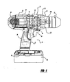
- a power tool constructed in accordance with the present teachings is generally indicated by reference numeral 10.
- Various aspects of the present teachings may include either a cord or a cordless (battery operated) device, such as a portable screwdriver or a drill (e.g., drill, hammer drill and/or driver).
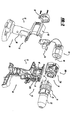
- the power tool 10 is illustrated as a cordless drill having a housing 12, a motor assembly 14, a multi-speed transmission assembly 16, a clutch mechanism 18, an output spindle assembly 20 (including a hammer mechanism 19, Figure 3 ) contained within a spindle housing 21, a chuck 22, a trigger assembly 24, a battery pack 26 and a holder 28.
- the housing 12 may include an end cap assembly 30 and a handle shell assembly 32 that may include a pair of mating handle shells 34.
- one mating handle shell may be referred to as the assembly side, while the other side may be referred to as the cover side.
- the handle shell assembly 32 may include a handle portion 36 and a drive train or a body portion 38.
- the trigger assembly 24 and the battery pack 26 may be mechanically coupled to the handle portion 36 and may be electrically coupled to the motor assembly 14.
- the body portion 38 may include a motor cavity 40 and a transmission cavity 42.
- the motor assembly 14 may be housed in the motor cavity 40 and may include a rotatable output shaft 44, which may extend into the transmission cavity 42.
- a motor pinion 46 having a plurality of gear teeth 48 may be coupled for rotation with the output shaft 44, as illustrated in Figure 3 .
- the trigger assembly 24 and the battery pack 26 may cooperate to selectively provide electrical power to the motor assembly 14 in a suitable manner to selectively control the speed and/or direction at which output shaft 44 may rotate.
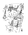
- the transmission assembly 16 may be housed in the transmission cavity 42 and may include a speed selector mechanism 60.
- the motor pinion 46 may couple the transmission assembly 16 to the output shaft 44 to transmit a relatively high speed but relatively low torque drive input to the transmission assembly 16.
- the transmission assembly 16 may include a plurality of reduction elements or reduction gearsets that may be selectively engaged (and disengaged) by the speed selector mechanism 60 to provide a plurality of user-selectable speed ratios. Each of the speed ratios may multiply the speed and the torque of the drive input in a predetermined manner, permitting the output speed and the torque of the transmission assembly 16 to be varied in a desired manner between a relatively low speed but high torque output and a relatively high speed but low torque output.
- the output from the transmission assembly 16 may be transmitted to the output spindle assembly 20 ( Figure 2 ).
- the chuck 22 ( Figure 2 ) may be incorporated in or coupled for rotation with the output spindle assembly 20 to permit torque to be transmitted to, for example, a tool bit (not shown).
- the clutch mechanism 18 (also in Figure 15 ) may be coupled to the transmission assembly 16 and may be operable for limiting the magnitude of the torque associated with the drive input to a predetermined and selectable torque limit.
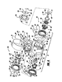
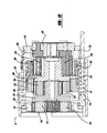
- the transmission assembly 16 may be a three-stage, three-speed transmission that may include a transmission sleeve 200, a reduction gearset assembly 202 and the speed selector mechanism 60.
- the transmission sleeve 200 may include a wall member 204 that generally may define a transmission bore or a hollow cavity 206 into which the reduction gearset assembly 202 may be contained.
- the transmission sleeve 200 may include a body 208 and a base 210.
- the body 208 of the transmission sleeve 200 may be generally uniform in diameter and may be smaller in diameter than the base 210.
- the base 210 may include a pair of bosses 212 formed along an outer periphery of the base 210. Also, a pin housing 214 may be formed in the base 210 and the body 208. As shown in Figure 2 , the mating shells 34 may each include a groove 216 formed on an interior surface of the mating shell 34. Each groove may receive an associated boss 212 that may be formed on the transmission sleeve 200. In this regard, each groove 216 may align and/or may hold the transmission sleeve 200 in the handle mating shells 34 ( Figure 2 ) and may inhibit relative rotation between the transmission sleeve 200 and the housing 12 ( Figure 2 ).
- the pair of bosses 212, the pair of grooves 216 and the pin housing 214 may be configured in a manner such that the transmission sleeve 200 may only be assembled to the handle shells 34 in one orientation (e.g., the speed selector mechanism 60 upward and the pin housing 214 downward relative to Figure 3 ).
- the body 208 of the transmission sleeve 200 may include a first and a second set of ring engagement teeth 218 and 220, respectively formed on an inner surface 222 of the body 208.
- a raised bead 224 may extend from the inner surface 222 (i.e., integral to or coupled together) and may segregate the inner surface 222 of the body 208 into first and second housing portions 227 and 229, respectively.
- the first set of ring engagement teeth 218 may extend from the inner surface 222 of the body 208 (i.e., may be integral to or may be coupled together) and may extend rearwardly from the raised bead 224 toward the base 210.
- the second set of ring engagement teeth 220 may also be formed onto the inner surface 222 of the body 208 but may extend forwardly from the raised bead 224 away from the base 210 and may be similar to that of the first set of engagement teeth 218.
- teeth 226 of the first and second sets of ring engagement teeth 218, 220 may be uniformly spaced a dimension 228 around the inner surface 222 of the body 208 and may be aligned along a single diametral plane 230.
- the configuration of each tooth 226 in the first and second sets 218, 220 may be similar in that each tooth 226 may extend from the raised bead 224, may have a pair of generally parallel engagement surfaces 232 and may terminate at a tip portion 234.
- the tip portion 234 of each tooth 226 may be both rounded and tapered to enhance the ability with which it may mesh with a portion of the reduction gearset assembly 202.
- a first set 236 of the teeth 226 in the first and/or second sets of ring engagement teeth 218, 220 may be longer than a second set 238 of teeth 226.
- the second set 238 may be the remaining teeth, i.e., the other teeth 226 besides the teeth 226 from the first set 236.
- the four teeth (or some suitable portion of the total amount of teeth 226) may define a dimension 240 from the raised bead 224 to the tip portion 234.
- the teeth 226 of the second set 238 may define a dimension 242 from the raised bead 224 to the tip portion 234.
- the dimension 240 may be greater (i.e., longer) than the dimension 242 such that the teeth 226 in the first set 236 may be longer (axially) than the teeth 226 in the second set 238.
- the teeth 226 in the first set 236 may be longer than the teeth 226 in the second set 238 on either or both sides of the raised bead 224 or diametral plane 230.
- the teeth 226 of the first set 236 and the second set 238 may also be the same length.
- the tip portions 234 of the teeth 226 in the first set 236 may be offset and thus a greater distance from the raised bead 224 and/or the diametral plane 230 of the teeth 226 of the second set 238.
- the teeth 226 in the first set 236 and/or the second set 238 may not connect or be integral to the raised bead 224 but may be spaced therefrom in contrast to the teeth 226 straddling or integral to the raised bead 224, as illustrated in Figure 7 .
- the pin housing 214 may extend downwardly from the body 208 and along a majority of the body 208.
- An actuator aperture 244 may be formed in the pin housing 214 and may extend rearwardly through the base 210 of the transmission sleeve 200.
- the actuator aperture 244 may be stepped or may taper and may include a first portion 246 with a first diameter at a rear (i.e., left in Figure 7 ) of the transmission sleeve 200 and a second portion 248 with a smaller second diameter at a front (i.e., right in Figure 7 ) of the transmission sleeve 200.
- the second portion 248 of the actuator aperture 244 may break through a wall of the second housing portion 229 and may form a groove 250 in an outer surface 252 of the body 208 (also shown in Figure 8A ).
- a pair of first clip slots 254 and a pair of second clip slots 256 may be formed into (or through) the transmission sleeve 200, extending along the sides of the transmission sleeve 200 in a manner that may be generally parallel to a longitudinal axis 258 of the transmission sleeve 200.
- the first pair of clip slots 254 may be formed through the sides of the body 208 rearwardly of the raised bead 224.
- the first pair of clip slots 254 may extend rearwardly toward the base 210 or through a portion thereof and may terminate at (or near) the bosses 212.
- the second pair of clip slots 256 may be also formed through the sides of the body 208 beginning forwardly of the raised bead 224 and may extend through (i.e., open to) a front face 260 of the transmission sleeve 200.
- the reduction gearset assembly 202 may include a first reduction gear set 302, a second reduction gear set 304 and a third reduction gear set 306.
- the first, second and third reduction gear sets 302, 304 and 306 may be operable in an active mode, as shown in Figure 12 .
- the second and third reduction gear sets 304 and 306 may also be operable in an inactive mode.
- Figure 13 shows the third reduction gearset 306 in the inactive mode
- Figure 14 shows the second reduction gearset 306 in the inactive mode. Operation in the active mode may cause the reduction gear set to perform the speed reduction and torque multiplication operation.
- operation of the reduction gear set in an inactive mode may cause the reduction gear set to provide an output having a speed and torque that may be about equal to the speed and torque of the rotary input provided to that reduction gear set.
- Each of the first, second and third reduction gear sets 302, 304 and 306 may be planetary gear sets. It will be appreciated that various other types of reduction gear sets are known in the art may be substituted for one or more of the reduction gear sets forming the reduction gear set assembly 202.
- the first reduction gear set 302 may include a first reduction element or the first ring gear 310, a first set of planet gears 312 and a first planet or reduction carrier 314.
- the first ring gear 310 may be an annular structure, having a plurality of gear teeth 310a formed along its interior diameter.
- a clutch face 316 may be formed from or may be coupled to the front face 318 of the first ring gear 310 and may terminate or be near an outer periphery of the first ring gear 310.
- the first reduction carrier 314 may be formed in the shape of a flat cylinder, having plurality of pins 322 that extend from its rearward face 324 (i.e., toward the motor pinion 46).
- a plurality of gear teeth 314a may be formed into the outer periphery of the first reduction carrier 314.
- the gear teeth 314a may be formed into the entire outer periphery or a portion thereof, as described in United States Patent Number 6,676,557 already incorporated by reference.
- the total quantity of gear teeth 314a may be reduced by approximately 20% to about 35% relative to a quantity of gear teeth that could be formed on the outer periphery of the first reduction carrier 314.
- the first thrust washer 332 and the transmission sleeve 200 may be configured to cooperate with one another to permit the first thrust washer 332 to be fixedly but removably coupled to the transmission sleeve 200 in a robust and reliable manner.
- the first thrust washer 332 may have a circular planar portion 334, a central aperture 336 and a plurality of retaining tabs 338.
- Each retaining tab 338 may include a plurality of fingers 342 which may be disposed in a common plane when the thrust washer 332 has not been installed to the transmission sleeve 200.
- the transmission sleeve 200 may be configured so as to define a pair of mounts 339 that may be located proximate the bosses 212.
- Each mount 339 may include a void space 341, which may be configured to receive an associated retaining tab 338 when the thrust washer 332 may be axially received into the base 210, as well as a clamping portion 340.
- Each clamping portion 340 may include a circumferentially extending slot 340a, which may intersect one of the void spaces 341 and a stop member 340b.
- the stop member 340b may be a bump or protrusion that extends into the slot 340a and which may be sized relatively smaller than a distance between two of the fingers 342 of the retaining tabs 338 of the thrust washer 332. Accordingly, when the thrust washer 332 is secured to the transmission sleeve 200, rotation of the thrust washer 332 may cause a first one of the fingers 342 to resiliently deflect and ride over the stop member 340b. Alignment of the gap between the fingers 342 to the stop member 340b may operably resist movement of the thrust washer 332 relative to the transmission sleeve 200. Alternatively, the stop member 340b may engage the one of the fingers 342 to secure the thrust washer 332 to the transmission sleeve 200.
- the central aperture 336 may be formed in a non-circular manner. Accordingly, a correspondingly shaped tool (not shown) may be inserted into the central aperture 336 and employed to transmit drive torque to the thrust washer 332 to cause the thrust washer 332 to rotate within the base 210 of the transmission sleeve 200.
- the second reduction gear set 304 may be disposed within the portion of the hollow cavity 206 defined by the first housing portion 227 and may include a second sun gear 358, a second reduction element or ring gear 360, a second set of planet gears 362 and a second planet or reduction carrier 364.
- the motor pinion 46 may serve as a sun gear for the first reduction gearset 302.
- the second sun gear 358 may be fixed for rotation with the first reduction carrier 314.
- the second sun gear 358 may include a plurality of gear teeth 358a that may extend forwardly (i.e., away from the motor pinion 46) of the forward face 328 of the first reduction carrier 314.
- the second ring gear 360 may be an annular structure, having a plurality of gear teeth 360a formed along an interior surface associated with its inner diameter.
- the second reduction gearset 304 may include the second reduction carrier 364 having a plurality of pins 366 holding the second set of planet gears 362.
- the gear teeth 360a formed along the interior diameter of the second ring gear 360 and, among other things, their engagement with the planet gears 362 on the second reduction carrier 364 are outside the scope of the present disclosure but are discussed in further detail in one or more of the captioned references already incorporated by reference above.
- a plurality of sleeve engagement teeth 368 may be formed into an outer periphery of the second ring gear 360.
- the sleeve engagement teeth 368 may extend forwardly (i.e., away from the motor spindle 46) toward a front face 370 of the second ring gear 360 and may terminate at a tip portion 372 that may be rounded and may taper forwardly and/or inwardly.
- An annular clip groove 374 may also formed in the outer periphery of the second ring gear 360.
- the clip groove 374 may be formed as a generally rectangular slot having a pair of sidewalls that may hold a portion of a wire clip 522 discussed below.
- the third reduction gear set 306 may be disposed within the portion of the hollow cavity 206 defined by the second housing portion 229 and may include a third sun gear 398, a third reduction element or ring gear 400, a third set of planet gears 402 and a third planet or reduction carrier 404.
- the third sun gear 398 may be fixed for rotation with the second reduction carrier 364 and may include a plurality of gear teeth 398a that may be meshingly engaged to the third set of planet gears 402.
- the third planet carrier 404 may be generally similar to the first planet carrier 314 and may be employed to journal the third set of planet gears 402.
- a plurality of gear teeth 404a may be formed into the outer periphery of the third reduction carrier 404.
- the gear teeth 404a may be formed into the entire outer periphery or a portion thereof, as described in United States Patent Number 6,676,557 already incorporated by reference. In the particular example provided, the total quantity of gear teeth 404a may be reduced by approximately 20% to about 35% relative to a quantity of gear teeth that could be formed on the outer periphery of the third reduction carrier 404.
- the third ring gear 400 may be an annular structure having a plurality of gear teeth 400a formed along its inner periphery associated with an interior diameter.
- the engagement of the gear teeth 400a with the planet gears 402 is outside the scope of the present disclosure but is discussed in further detail in the referenced disclosures already incorporated by reference above.
- a plurality of sleeve engagement teeth 412 may be formed into the outer periphery of the third ring gear 400.
- the sleeve engagement teeth 412 may extend rearward toward the rear face 414 of the third ring gear 400 and may terminate at a tip portion 416, each of which may be rounded and/or may taper rearwardly and/or inwardly.
- An annular clip groove 418 may also be formed into the outer periphery of the third ring gear 400.
- the clip groove 418 may be formed as a generally rectangular slot having a pair of sidewalls that may hold a portion of a wire clip 522 discussed below.
- a second thrust washer 420 may be disposed around the third sun gear 398 between the third ring gear 400 and the second ring gear 360.
- the second thrust washer 420 may include a plurality of retaining tabs 422 that may be configured to engage corresponding tab grooves 424 that may be formed in the inner surface 222 of body 208 of the transmission sleeve 200, as illustrated in Figure 7 .
- the retaining tabs 422 and the tab grooves 424 ( Figure 7 ) may cooperate to inhibit relative rotation between the second thrust washer 420 and the transmission sleeve 200.
- the output spindle assembly 20 may include an anvil 426 that may be part of a spindle lock assembly 428 or a one-way clutch.
- the anvil 426 which is discussed in further detail below, may couple an output spindle 430 associated with the output spindle assembly 20 ( Figure 3 ) to the third reduction carrier 404 so as to transmit drive torque from the reduction gearset assembly 202 to ultimately the chuck 22 ( Figure 1 ).
- the speed selector mechanism 60 may be movable between a first position 500, a second position 502 and a third position 504, as shown in Figure 10 .
- the speed selector mechanism 60 may include a switch body 506 having an actuator portion 508 for receiving a speed change input and for connecting to a rotary selector cam 520.
- the actuator portion 508 may be operatively coupled to the reduction gearset assembly 202 and ultimately may be used to move the second and third reduction gear sets 304 and 306 between the active and inactive modes in response to movement of the actuator portion 508 between the first, second and third positions 500, 502 and 504.
- the speed selector mechanism 60 may include the rotary selector cam 520, a plurality of wire clips 522 and a spring member 523.
- Each of the wire clips 522 may be formed from a round or other suitable wire which may be bent in the shape of a semi-circle 524 with a pair of tabs 526 extending outwardly from the semi-circle 524 and positioned on about the centerline of the semi-circle 524.
- the semi-circle 524 may be sized to fit within the clip grooves 374 and 418 in the second and third ring gears 360 and 400, respectively.
- the tabs 526 of the wire clips 522 may extend outwardly of the hollow cavity 206 into an associated one of the clip slots 254, 256 that may be formed into the transmission sleeve 200.
- the tabs 526 may be long enough so that they may extend outwardly of the outer surface 252 of the body 208 of the transmission sleeve 200, but not so far as to extend radially outward of a periphery of the base 210 of the transmission sleeve 200. Configuration of the wire clips 522 in this manner may facilitate the assembly of the transmission assembly 16 and may permit the wire clips 522 to be installed on the second and third ring gears 360 and 400. After assembly and installation, these assemblies may be inserted into the hollow cavity 206 along the longitudinal axis 258 ( Figure 5 ) of the transmission sleeve 200.
- the rotary selector cam 520 may include an arcuate selector body 530 (also shown in Figure 4 ), a switch tab 532 and a plurality of spacing members 534.
- a pair of first cam slots 540a and 540b, a pair of second cam slots 544a and 544b, a spring aperture 546 and a guide aperture 548 may be formed through the selector body 530.
- the selector body 530 may be sized to engage the outside diameter of the body 208 of the transmission sleeve 200 in a slip-fit manner, but still rotate relative thereto.
- the guide aperture 548 may be generally rectangular in shape and sized to engage the front and rear surfaces of the selector cam guide 550 ( Figure 5 ).
- the guide aperture 548 may be considerably wider than the width of the selector cam guide 550 and may be sized in this manner to permit the rotary selector cam 520 to be rotated on the transmission sleeve 200 between a first rotational position 500, a second rotational position 502 and a third rotational position 504.
- the selector cam guide 550 may cooperate with the guide aperture 548 to limit the amount by which the rotary selector cam 520 may be rotated on the transmission sleeve 200.
- a first lateral side of the selector cam guide 550 may contact a first lateral side of the guide aperture 548 when the rotary selector cam 520 may be positioned in the first rotational position 500.
- a second lateral side of the selector cam guide 550 may contact a second lateral side of the guide aperture 548 when the rotary selector cam 520 may be positioned in the third rotational position 504.
- each of the first cam slots 540a and 540b may be sized to receive one of the tabs 526 of the wire clip 522 that may be engaged to the second ring gear 360.
- the first cam slot 540a may include a first segment 552, a second segment 554 and an intermediate segment 556.
- the first segment 552 may be located a first predetermined distance away from a reference plane 558, which may be perpendicular to the longitudinal axis of the rotary selector cam 520.
- the second segment 554 may be located a second distance away from the reference plane 558.
- the intermediate segment 556 may couple the first and second segments 552 and 554 to one another.
- first cam slot 540b may be identical to that of first cam slot 540a, except that it may be rotated relative to the rotary selector cam 520 such that each of the first, second and intermediate segments 552, 554 and 556 in the first cam slot 540b may be located one hundred eighty degrees apart from the first, second and intermediate segments 552, 554 and 556 in the first cam slot 540a.
- Each of the second cam slots 544a and 544b may be sized to receive one of the tabs 526 of a corresponding one of the wire clips 522.
- the second cam slot 544a may include a first segment 560, a second segment 562, a third segment 564 and a pair of intermediate segments 566 and 568.
- the first and third segments 560 and 564 may be located a third predetermined distance away from the reference plane 558 and the second segment 562 may be located a fourth distance away from the reference plane 558.
- the intermediate segment 566 may couple the first and second segments 560 and 562 to one another and the intermediate segment 568 may couple the second and third segments 562 and 564 together.
- the first segment 552 may be closed at one end of the rotary selector cam 520, which may be shown to improve the structural rigidity of the rotary selector cam 520.
- the first segment 552, the intermediate segment 556 and the second segment 554 may form a closed channel 552a such that the wire clip 522 may travel within the channel 552a but may not travel outside the channel 552a once inserted into the channel 552a.
- second cam slot 544b may be identical to that of second cam slot 544a, except that it may be rotated relative to the rotary selector cam 520 such that each of the first, second, third and intermediate segments 560, 562, 564 and 566 and 568 in the second cam slot 544b may be located one hundred eighty degrees apart from the first, second, third and intermediate segments 560, 562, 564 and 566 and 568 in the second cam slot 544a.
- the rotary selector cam 520 may be rotated on the transmission sleeve 200 between the first, second and third positions 500, 502 and 504 ( Figure 10 ) to selectively engage and disengage the second and third ring gears 360 and 400 from the first and third reduction carriers 364 and 404, respectively.
- the first cam slots 540a and 540b and the second cam slots 544a and 544b may confine the wire tabs 526 of their associated wire clip 522 and may cause the wire tabs 526 to travel along the longitudinal axis 258 ( Figure 5 ) of the transmission sleeve 200 in an associated one of the first and second clip slots 254 and 256. Accordingly, the rotary selector cam 520 may be operative for converting a rotational input to an axial output that may cause the wire clips 522 to move axially in the predetermined manner explained above.
- positioning the rotary selector cam 520 in the first rotational position 500 may cause the tabs 526 of the wire clip 522 that may be engaged to the second ring gear 360 to be positioned in the first segment 552 of the first cam slots 540a and 540b.
- the tabs 526 of the wire clip 522 that may be engaged to the third ring gear 400 may be positioned in the first segment 560 of the second cam slots 544a and 544b. Accordingly, positioning of the rotary selector cam 520 in the first rotational position may cause the second and third ring gears 360 and 400 to be positioned in meshing engagement with the second and third planet gears 362 and 402, respectively.
- the sleeve engagement teeth 368 and 412 of the second and third ring gears 360 and 400 may be positioned in meshing engagement with the first and second sets of ring engagement teeth 218 and 220,.
- the meshing engagement may inhibit relative rotation between the second and third ring gears 360 and 400 and the transmission sleeve 200 and thereby may provide the transmission assembly 16 with a first overall gear reduction or speed ratio 570, as shown in Figure 12 .
- the first set 236 of teeth 226 may be longer and/or may be offset longitudinally from the second set 238 of teeth 226, which may be shown to ease engagement of the second and/or third ring gears 360, 400.
- positioning the rotary selector cam 520 in the second rotational position 502 may cause the tabs 526 of the wire clip 522 that may be engaged to the second ring gear 360 to be positioned in the first segment 550 of the first cam slots 540a and 540b.
- the tabs 526 of the wire clip 522 may be engaged to the third ring gear 400 and may be positioned in the second segment 562 of the second cam slots 544a and 544b.
- positioning of the rotary selector cam 520 in second rotational position 502 causes the second ring gear 360 to be in meshing engagement with the second planet gears 362 and the third ring gear 400 in meshing engagement with both the third planet gears 402 and the third reduction carrier 404.
- Positioning of the rotary selector cam 520 in the second rotational position 502 may also position the sleeve engagement teeth 368 of the second ring gear 360 in meshing engagement with the first set of ring engagement teeth 218, while the sleeve engagement teeth 412 of the third ring gear 400 may not be engaged (not meshed) with the second set of ring engagement teeth 220.
- positioning the rotary selector cam 520 in the third rotational position 504 may cause the tabs 526 of the wire clip 522 that may be engaged to the second ring gear 360 to be positioned in the second segment 552 of the first cam slots 540a and 540b.
- the tabs 526 of the wire clip 522 may be engaged to the third ring gear 400 and may be positioned in the third segment 564 of the second cam slots 544a and 544b.
- positioning of the rotary selector cam 520 in the third rotational position 504 may cause the second ring gear 360 to be in meshing engagement with both the second planet gears 362 and the first reduction carrier 314,while the third ring gear 400 in meshing engagement with only the third planet gears 402.
- Positioning the rotary selector cam 520 in the third rotation position 504 may also position the sleeve engagement teeth 368 on the second ring gear 360 out of meshing engagement with the first set of ring engagement teeth 218 and the sleeve engagement teeth 412 on the third ring gear 400 in meshing engagement with the second sets of ring engagement teeth 220.
- relative rotation between the second ring gear 360 and the transmission sleeve 200 may be permitted while, relative rotation between the third ring gear 400 and the transmission sleeve 200 may be inhibited to thereby provide the transmission assembly 16 with a third overall gear reduction or speed ratio 574, as shown in Figure 14 .
- rotary selector cam 520 i.e., the first cam slots 540a and 540b and the second cam slots 544a and 544b
- the rotary selector cam 520 could be configured somewhat differently so as to cause the second ring gear 360 to engage (mesh with) both the second planet gears 362 and the first reduction carrier 314, while the third ring gear 400 may engage (mesh with) both the third planet gears 402 and the third reduction carrier 404 to thereby providing the transmission assembly 16 with a fourth overall gear reduction or speed ratio.
- a cover 576 may connect to the transmission sleeve 200 on a side opposite the base 210.
- the cover 576 may be attached to the transmission sleeve 200 via a snap-fit.
- the cover 576 may include an annular flange 578 that may include a groove 580 ( Figure 8C ) formed within an inner surface 582 of the annular flange 578.
- the annular flange 578 may be configured in multiple separate sections so as not to interfere with the rotary cam selector 520 (as shown in Figure 8D ), as it moves between positions relative to the transmission sleeve 200.
- the groove 580 formed on the inner surface 582 of the annular flange 578 may receive a circumferentially extending raised bead or rib 584 formed on the outer surface 252 of the transmission sleeve 200.
- the raised bead or rib 584 may be integral to or may be coupled to the transmission sleeve 200 and may form a complete annular structure or may otherwise be a plurality of sections.
- an indentation 586 that may be formed on the cover 576 at one or more locations may receive a portion of the clutch engagement assembly 702 (i.e., a clutch pin) as discussed in further detail below.
- a portion of the clutch engagement assembly 702 i.e., a clutch pin
- the cover 576 may be installed onto the transmission sleeve 200 at one or more preselected orientations. As such, it may be shown that an improper installation orientation may be prevented. As illustrated, the cover 576 may be assembled to the transmission sleeve 200 in two orientation-specific positions.
- the cover 576 may index against a portion of the engagement assembly 702. Moreover, when the cover 576 may be secured to the transmission sleeve 200, the cover 576 and more specifically the annular flange 578 may not interfere with the movement of the rotary selector cam 520. It will be appreciated that in other examples the cover 576 may have one or a plurality of indexing position and an associated configuration of the annular flanges that do not interfere with the rotary selector cam 520.
- the thrust washer 332 may be attached to the rear portion of the transmission sleeve 200 (near the motor pinion 46) and the cover 576 may be snap-fit to the front of the transmission sleeve 200.
- the transmission components i.e., the first, second and/or third reduction sets among other things
- the transmission cassette 588 may be removed from the tool housing 12 as a self-contained unit and thus the propensity of the various transmission components falling out of the transmission sleeve 200 may be shown to be reduced.
- the cover 576 may also include a plurality of raised bosses 590 formed on the front face of the cover that may include apertures 592 that may receive tangs 594 formed on a front washer 596.
- the front washer 596 may be part of the spindle lock assembly 428.
- the front washer 596 may have an aperture 598 formed in generally the middle of the front washer 596.
- the output spindle 430 that may be associated with the output spindle assembly 20 may be received by the anvil 426 through the front washer 596.
- the clutch mechanism 18 may include a clutch member 700, an engagement assembly 702 and an adjustment mechanism 704.
- the clutch member 700 may be an annular structure that may be fixed to the outer diameter of the first ring gear 310 and which may extend radially outward therefrom (i.e., away from the motor pinion 46).
- the clutch member 700 may include the clutch face 316 that may be formed into the front axial face 318 of the first ring gear 310.
- the outer periphery of the clutch member 700 may be sized to rotate within the portion of the hollow cavity 206 that may be defined by the base 210 of the transmission sleeve 200.
- the engagement assembly 702 may include a pin member 720, a follower spring 722 and the follower 724.
- the pin member 720 may include a cylindrical body portion 730 having an outer diameter that may be sized to slip-fit within the second portion 248 of the actuator aperture 244 that may be formed into the pin housing 214 of the transmission sleeve 200, as shown in Figure 7 .
- the pin member 720 may also include a tip portion 732 and a head portion 734.
- the tip portion 732 may be configured to engage the adjustment mechanism 704.
- the tip portion 732 may be formed into the end of the body portion 730 of the pin member 720 and may be defined by a spherical radius.
- the head portion 734 may be coupled (or may be integral) to the body portion 730 and spaced from the tip portion 732 and may be shaped in the form of a flat cylinder or barrel that may be sized to slip fit within the first portion 246 of the actuator aperture 244 ( Figure 7 ). Accordingly, the head portion 734 may prevent the pin member 720 from being urged forwardly out of the actuator aperture 274.
- the follower spring 722 may be a compression spring whose outside diameter may be sized to slip fit within the first portion 246 of the actuator aperture 244 ( Figure 7 ).
- the forward end of the follower spring 722 may contact the head portion 734 of the pin member 720, while the opposite end of the follower spring 722 may contact the follower 724.
- the tip portion 740 of the follower 724 may have a rounded or spherical shape and may be configured to engage the clutch face 316.
- the follower 724 may also include an end portion 744 having a cylindrically shaped body portion 746, a tip portion 748 and a flange portion 750.
- the body portion 746 may be sized to slip fit within the first portion 246 of the actuator aperture 244.
- the flange portion 750 may be formed where the body portion 746 extends outward away from the tip portion 740.
- the flange portion 750 may be generally flat and configured to receive a biasing force that may be exerted by the follower spring 722.
- the end portion 744 of the follower may act as a spring follower to prevent the follower spring 722 from bending over when it may be compressed.
- an alternative tip portion 752 may be configured to enclose a portion of a ball bearing 754.
- the tip portion 752 may include one or more tangs 756 that may hold the ball bearing 754 within an aperture 752a formed within the tip portion 752. As illustrated, five tangs 756 may capture the ball bearing 754 within the tip portion 752.
- the tangs 756 of the tip portion 752 may be configured such that the ball bearing 754 may roll against the clutch face 316.
- the employment of the rolling ball bearing 754 may be shown to reduce friction at the interface the tip portion 752 and the clutch face 316 relative to a solid (unitary) tip portion 740.
- a flange portion 758 may be formed at the intersection between a body portion 760 and an end portion 762, and may be similar to that of the tip portion 740.
- a tip portion 764 that may hold the ball bearing 754 may be configured in a two-piece configuration.
- the tip portion 764 may include two portions 766, 768 that may be fastened to one another using, for example, threads or another suitable fastening means.
- the ball bearing 754 may be inserted between the two portions 766, 768, which may be fastened together and may urge the ball bearing 754 toward the tangs 756. It may be shown that manufacturing processes (e.g., heat treat or hardening) may be performed on portion 766 and/or portion 768 of the tip portion 764 and then later assembled to include the ball bearing 754.
- the adjustment mechanism 704 may also include an adjustment structure 770 and a setting collar 772.
- the adjustment structure 770 may be shaped in the form of a generally hollow cylinder that may be sized to fit over the spindle housing 21 of the output spindle assembly 20 ( Figure 3 ).
- the adjustment structure 770 may include an annular face 774 into which an adjustment profile 776 may be formed.
- Other features of the clutch mechanism 18 are disclosed in the references already incorporated by reference above.
- an initial drive torque may be transmitted by the motor pinion 46 from the motor assembly 14 to the first set of planet gears 312 causing the first set of planet gears 312 to rotate.
- a first intermediate torque may be applied against the first ring gear 310. Resisting this torque may be a clutch torque that may be applied by the clutch mechanism 18.
- the clutch torque inhibits the free rotation of the first ring gear 310, causing the first intermediate torque to be applied to the first reduction carrier 314 and the remainder of the reduction gearset assembly 202 so as to multiply the first intermediate torque in a predetermined manner according to the setting of the speed selector mechanism 60.
- the clutch mechanism 18 may bias the first reduction gear set 302 in the active mode.
- the magnitude of the clutch torque may be dictated by the adjustment mechanism 704, and more specifically, the relative height of the adjustment profile 776 that may be in contact with the tip portion 732 of the pin member 720. Positioning of the adjustment mechanism 704 at a predetermined portion of the adjustment profile 776 may push the pin member 720 rearwardly in the actuator aperture 244, thereby compressing the follower spring 722 and producing the clutch force.
- the clutch force may be transmitted to the flange portion 750 of the follower 724, causing the tip portion 740 of the follower 724 to engage the clutch face 316 and generate the clutch torque.
- Positioning of the tip portion 740 of the follower 724 in one of the valleys 778 in the clutch face 316 may operate to inhibit rotation of the first ring gear 310 relative to the transmission sleeve 200 when the magnitude of the clutch torque exceeds the first intermediate torque.
- the first ring gear 310 may be permitted to rotate relative to the transmission sleeve 200.
- rotation of the first ring gear 310 may cause the clutch force to increase a sufficient amount to resist further rotation.
- the first ring gear 310 may rotate in an opposite direction when the magnitude of the first intermediate torque diminishes, permitting the tip portion 740 of the follower 724 to align in one of the valleys 778 in the clutch face 316. If rotation of the first ring gear 310 does not cause the clutch force to increase sufficiently so as to fully resist rotation of the first ring gear 310, the first reduction gearset 302 may rotate so as to limit the transmission of torque to the first reduction carrier 314, i.e., no torque multiplication.
- the first ring gear 310 may be configured with an annular wall 780 that may be adjacent the clutch face 316.
- the annular wall 780 may be at angle 782 that may be obtuse to the clutch face 316.
- a value of the angle 782 between the annular wall 780 and the clutch face 316 may be preferably about ninety five degrees to about one hundred fifty degrees but in the present example the value of the angle 782 may be more preferably about one hundred eleven degrees.
- the wall 780 may include a first surface 784 and a second surface 786. The first surface 784 may extend from the clutch face at the obtuse angle 782.
- the second surface 786 may extend from the first surface 784 and may also extend from an inner surface 788 of the first ring gear 310 that may be associated with an inner diameter.
- the inner surface 788 may have gear teeth 310a.
- the second surface 786 may be generally parallel to the clutch face 316 and may be generally perpendicular to the inner surface 788.
- the value of the angle 782 formed between the first surface 784 of the wall 780 adjacent to the clutch face 316 face may also vary based on the circumferential position about the ring gear 316. In other examples, however, the value of the angle 782 formed between the first surface 784 of the wall 780 and the clutch face 316 may be fixed and thus not based on the circumferential position about the ring gear 316.
- the housing 12 may be formed of two mating shells 34 that may be brought together to form the housing 12 of the tool 10.
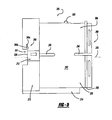
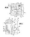
- a portion of the housing 12 above the trigger assembly 24 may be configured with a tongue and groove 800 configuration.
- a portion of the housing 12 above the trigger assembly 24 or trigger mount may include a first groove 802 that receives a first tongue 804 formed on the spindle housing 21.
- the portion of the housing 12 above the trigger assembly 24 may also include a second groove 806 that receives a second tongue 808 also formed on the spindle housing 21.
- the second groove 806 may be laterally spaced apart from the first groove 802.
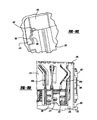
- the spindle housing 21 may include a boss or a rib 810 that extends from the spindle housing 20.
- the boss 810 may contact a base 812, when the spindle housing 21 connects to the housing 12.
- one or more suitable fasteners 814 may connect the spindle housing 21 to the housing 12.
- the pair of grooves 802, 806 and the base 812 may be part of a connection face 816 formed on the housing 12.
- the connection face 816 may mate with a connection face 818 which may be formed on the spindle housing 21 and may include the tongues 804, 808 and the boss 810.
- connection faces 816, 818 When the connection faces 816, 818 are joined together, the tongues 804, 808 may be secured to the grooves 802, 806. Moreover, the boss or a rib 810 that may contact the base 812 may slightly deflect as the connection faces 816, 818 may be brought together. In this regard, the housing 12 may be secured (at least temporarily) to the output spindle housing 21 and then the suitable fasteners may used to more securely attach the spindle housing 21 to the housing 12.
- the tool 10 may include the spindle lock assembly 428.
- the spindle lock assembly 428 may include the anvil 426, a plurality of roller elements or pins 902 interspersed between five projections 904 that may extend from a face 906 of the third planet carrier 404.
- a spindle lock ring 908 may contain the five pins 902 and keep the pins 902 aligned with the projections 904.
- the anvil 426 may be part of the drill or driver planetary gear transmission that transmits the power from the transmission to the output spindle assembly 20.
- the anvil 426 may allow movement between the third planet carrier 404 and the output spindle 430 in order to facilitate the spindle lock assembly 428.
- the spindle lock assembly 428 may provide an abutment to apply a force to the chuck 22 to, for example, tighten or loosen the chuck 22. When doing so, the spindle lock assembly 428 may prevent the tightening or loosening force from back-driving the transmission of the power tool 10.
- the face 906 of the third planet carrier 404 may include an aperture 910 in which a bottom portion 912 of the anvil 426 may be received.
- a gasket 914 between the anvil 426 and inner surface 916 of the aperture 910 formed in the third planet carrier 404 may be complementary in shape and/or size to the inner surface 916 and/or the shape of the bottom portion 912.
- the bottom portion 912 of the anvil 426 may be shaped in five-prong configuration 918 and, as such, the gasket 914 may have a similar configuration so that the gasket 914 may be disposed between the anvil 426 and the aperture 910 in the face 906 of the third planet carrier 404.
- an anvil 950 may be configured such that an aperture 952 that may be formed on the face 906 of the third planet carrier 404 may be a simple polygonal shape, such as a five-sided polygon. It will be appreciated that various suitable polygonal shapes may be used.
- a seal 954 may be disposed between the anvil 950 and the face 906. The seal 954 may further be disposed in a groove 956 formed on a face 957 of a top portion 918 of the anvil 950. The groove 956 may hold the seal 954.
- the seal 954 may be a circular seal, e.g., an O-ring.
- the seal 954 may be disposed between the face 906 and the groove 956 but may not be disposed between the bottom portion 912 and the inner surface 916 of the aperture 952. It may be shown that the circular seal 954 may be less costly than a shape-specific seal 914.
- an aperture 958 formed in the anvil 950 may have four arcuate walls 960.
- two of the walls may be opposed and D-shaped, such that a round portion 962 of each D-shape may form the first wall 964 and the second wall 966.
- the third wall 968 and the fourth wall 970 may be opposed to one another and may form a convex shape.
- the convex shape may have an apex 972 such that the apex of each wall 968, 970 may be closer to a center 974 of the aperture 958 than the inner surface 916 of the aperture 958.
- the shape of the aperture 958 relative to the shape of an aperture 976 on the anvil 426 may be shown to reduce stress between the output spindle 430 and the anvil 950 relative to the anvil 426.
- the shape of the bottom portion 912 of the anvil 950 relative to the anvil 426 may permit the anvil 950 to be inserted into the aperture 952 at a plurality of orientations (i.e., five orientations for a five-sided bottom portion) relative to the anvil 426.
Abstract
Description
- This application claims the benefit of United States Provisional Application No.
60/765,490, filed on February 3, 2006 - This patent application may be related to the following references. United States Patent Number
6,676,557 , Serial Number09/964,078 6,857,983 ,Serial Number 10/755,250 2005/0043135 ,Serial Number 10/953,699 2006/0021771 , Serial Number11/237,112 6,984,188 ,Serial Number 10/384809 2004/0211576 ,Serial Number 10/792,659 WO02059491 WO2005/093290 6,502,648 , Serial Number09/965,108 WO02058883 11/256,595, filed October 21, 2005 - The present teachings generally relate to power tools such as rotatable drills, power screwdrivers, and rotatable cutting devices. More particularly, the present teachings relate to a housing that contains a gearbox for a multi-stage and multi-speed transmission for a drill or driver.
- Manufacturers have introduced rotary power tools that have variable speed motors and multi-stage multi-speed transmissions. The tools may provide the user with sufficient control over the output speed and the torque of the tool so as to facilitate diverse operations without resorting to additional specialized tools. While the tools have performed satisfactorily, there remains room in the art for improvements to increase performance and reduce complexity and cost.
- The present teachings generally include a power tool having a motor, an output member and a transmission disposed between the motor and the output member. The transmission includes a ring gear with opposite axial end faces. The power tool also includes a clutch for limiting an output of the transmission. The clutch includes an annular clutch face disposed about the ring gear. At least a portion of a side of the ring gear is configured such that an included angle between the annular clutch face and the at least a portion of the side of the ring gear is about ninety five degrees to about one hundred fifty degrees.
- Further areas of applicability will become apparent from the description provided herein and the claims appended hereto. It should be understood that the description and specific examples are intended for purposes of illustration only and are not intended to limit the scope of the present teachings.
- The drawings described herein are for illustration purposes only and are not intended to limit the scope of the present teachings.
-
Figure 1 is a side view of a power tool constructed in accordance with the present teachings. -
Figure 2 is an exploded perspective view of a portion of the power tool ofFigure 1 . -
Figure 3 is an exploded perspective view of a portion of the power tool ofFigure 1 showing a transmission assembly and a hammer drill assembly in accordance with the present teachings. -
Figure 4 is similar toFigure 3 and shows the transmission assembly in further detail. -
Figure 5 is a side view of a transmission sleeve in accordance with the present teachings. -
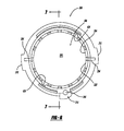
Figure 6 is a front view of the transmission sleeve ofFigure 5 . -
Figure 7 is a cross-sectional view taken fromFigure 6 . -
Figure 8A is a perspective view of the transmission sleeve ofFigure 5 and a cap that may be assembled to a front of the transmission sleeve in accordance with the present teachings. -
Figure 8B is similar toFigure 8A and shows the cap assembled to the transmission sleeve in accordance with the present teachings. -
Figure 8C shows a detailed assembly view of the cap and the transmission sleeve ofFigure 8B . -
Figure 8D is a side view of the annular flanges of the cap of the transmission sleeve configured to not interfere with motion of a rotary selector cam. -
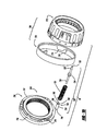
Figure 9A is a perspective view of the transmission sleeve ofFigure 5 and a thrust washer that is assembled to a rear of the transmission sleeve in accordance with the present teachings. -
Figure 9B is similar toFigure 9A and shows the thrust washer secured to the transmission sleeve in accordance with the present teachings. -
Figure 10 a is a top view of a speed selector mechanism and an adjuster mechanism assembled to a housing and showing positions that correspond to different speed ratios of the power tool in accordance with the present teachings. -
Figure 11 is a perspective view of the rotary selector cam in accordance with the present teachings. -
Figure 12 is a sectional view taken along the longitudinal axis of the transmission ofFigure 2 showing the transmission assembly positioned to provide a first speed ratio in accordance with the present teachings. -
Figure 13 is a sectional view similar toFigure 12 and shows the transmission assembly positioned to provide a second speed ratio. -
Figure 14 is a sectional view similar toFigure 12 and shows the transmission assembly positioned to provide a third speed ratio. -
Figure 15 is an exploded assembly view of an adjustable clutch mechanism in accordance with the present teachings. -
Figures 16 is a perspective view an exemplary alternative tip portion of a clutch pin from the clutch assembly ofFigure 15 showing a ball catch in accordance with the present teachings. -
Figure 16A is a side view of the tip portion ofFigure 16 . -
Figure 16B is front view of the tip portion ofFigure 16 . -
Figure 16C is a cross-section view taken throughFigure 16A . -
Figures 17, 17A, 17B and 17C are similar toFigures 16, 16A, 16B and 16C , respectively, and show an exemplary alternative tip portion having a two-piece construction in accordance with the present teachings. -
Figures 18A is a perspective view of a ring gear having a clutch face formed thereon showing a wall forming an obtuse angle with the clutch face in accordance with the present teachings. -
Figure 18B is a cross-section view taken throughFigure 18 . -
Figure 18C is similar toFigure 18B and shows the ring gear in further detail. -
Figure 19 is a perspective view of the housing of the power tool above a trigger assembly showing a connection face that receives a connection face on a spindle housing in accordance with the present teachings. -
Figure 20 is a perspective view of the spindle housing of the power tool showing the connection face that may be received by the connection face on the housing ofFigure 19 in accordance with the present teachings. -
Figure 21 is an exploded assembly view of the housing ofFigure 19 and the spindle housing ofFigure 20 showing a boss and a tongue on the spindle housing ofFigure 20 being received by a base and a groove, respectively, formed on the housing ofFigure 19 in accordance with the present teachings. -
Figure 22A is a perspective view of a planet carrier, an anvil and a portion of a spindle lock assembly in accordance with the present teachings. -
Figure 22B is an exploded assembly view of the planet carrier, the anvil and the portion of the spindle lock assembly ofFigure 22A and shows an anvil-specific gasket between the anvil and the planet carrier. -
Figure 23A is a perspective view of a planet carrier, anvil and portion of a spindle lock assembly in accordance with a further aspect of the present teachings. -
Figure 23B is an exploded assembly view of the planet carrier, the anvil and the portion of the spindle lock assembly ofFigure 23A and shows a circular gasket between the anvil and the planet carrier. -
Figure 23C is a perspective view of the anvil ofFigures 23A and 23B showing the circular gasket. -
Figure 23D is a front view of the anvil ofFigure 23C showing an aperture in which an output spindle may be received in accordance with the present teachings. - The following description merely exemplary in nature and is not intended to limit the present teachings, its application, or uses. It should be understood that throughout the drawings corresponding reference numerals indicate like or corresponding parts and features.
- With reference to
Figures 1 and2 , a power tool constructed in accordance with the present teachings is generally indicated byreference numeral 10. Various aspects of the present teachings may include either a cord or a cordless (battery operated) device, such as a portable screwdriver or a drill (e.g., drill, hammer drill and/or driver). InFigure 1 , thepower tool 10 is illustrated as a cordless drill having ahousing 12, amotor assembly 14, amulti-speed transmission assembly 16, aclutch mechanism 18, an output spindle assembly 20 (including ahammer mechanism 19,Figure 3 ) contained within aspindle housing 21, achuck 22, atrigger assembly 24, abattery pack 26 and aholder 28. It will be appreciated that a detailed discussion of several of the components of thepower tool 10, such as thehammer mechanism 19, thechuck 22, thetrigger assembly 24 and thebattery pack 26, are outside the scope of the present disclosure. Reference, however, may be made to a variety of publications for a more complete understanding of the operation and/or features that may be included in combination or individually with thepower tool 10. To that end, such publications include one or more of the references set forth above and already incorporated by reference. - With reference to
Figure 2 , thehousing 12 may include anend cap assembly 30 and ahandle shell assembly 32 that may include a pair ofmating handle shells 34. In one aspect, one mating handle shell may be referred to as the assembly side, while the other side may be referred to as the cover side. Thehandle shell assembly 32 may include ahandle portion 36 and a drive train or abody portion 38. Thetrigger assembly 24 and thebattery pack 26 may be mechanically coupled to thehandle portion 36 and may be electrically coupled to themotor assembly 14. Thebody portion 38 may include amotor cavity 40 and atransmission cavity 42. Themotor assembly 14 may be housed in themotor cavity 40 and may include arotatable output shaft 44, which may extend into thetransmission cavity 42. A motor pinion 46 having a plurality of gear teeth 48 may be coupled for rotation with theoutput shaft 44, as illustrated inFigure 3 . Thetrigger assembly 24 and thebattery pack 26 may cooperate to selectively provide electrical power to themotor assembly 14 in a suitable manner to selectively control the speed and/or direction at whichoutput shaft 44 may rotate. - With reference to
Figures 3 and4 , thetransmission assembly 16 may be housed in thetransmission cavity 42 and may include aspeed selector mechanism 60. The motor pinion 46 may couple thetransmission assembly 16 to theoutput shaft 44 to transmit a relatively high speed but relatively low torque drive input to thetransmission assembly 16. Thetransmission assembly 16 may include a plurality of reduction elements or reduction gearsets that may be selectively engaged (and disengaged) by thespeed selector mechanism 60 to provide a plurality of user-selectable speed ratios. Each of the speed ratios may multiply the speed and the torque of the drive input in a predetermined manner, permitting the output speed and the torque of thetransmission assembly 16 to be varied in a desired manner between a relatively low speed but high torque output and a relatively high speed but low torque output. The output from thetransmission assembly 16 may be transmitted to the output spindle assembly 20 (Figure 2 ). The chuck 22 (Figure 2 ) may be incorporated in or coupled for rotation with theoutput spindle assembly 20 to permit torque to be transmitted to, for example, a tool bit (not shown). The clutch mechanism 18 (also inFigure 15 ) may be coupled to thetransmission assembly 16 and may be operable for limiting the magnitude of the torque associated with the drive input to a predetermined and selectable torque limit. - The
transmission assembly 16 may be a three-stage, three-speed transmission that may include atransmission sleeve 200, areduction gearset assembly 202 and thespeed selector mechanism 60. With additional reference toFigures 5 through 7 , thetransmission sleeve 200 may include awall member 204 that generally may define a transmission bore or ahollow cavity 206 into which thereduction gearset assembly 202 may be contained. Thetransmission sleeve 200 may include abody 208 and abase 210. Thebody 208 of thetransmission sleeve 200 may be generally uniform in diameter and may be smaller in diameter than thebase 210. - The base 210 may include a pair of
bosses 212 formed along an outer periphery of thebase 210. Also, apin housing 214 may be formed in thebase 210 and thebody 208. As shown inFigure 2 , themating shells 34 may each include agroove 216 formed on an interior surface of themating shell 34. Each groove may receive an associatedboss 212 that may be formed on thetransmission sleeve 200. In this regard, eachgroove 216 may align and/or may hold thetransmission sleeve 200 in the handle mating shells 34 (Figure 2 ) and may inhibit relative rotation between thetransmission sleeve 200 and the housing 12 (Figure 2 ). In one example, the pair ofbosses 212, the pair ofgrooves 216 and thepin housing 214 may be configured in a manner such that thetransmission sleeve 200 may only be assembled to thehandle shells 34 in one orientation (e.g., thespeed selector mechanism 60 upward and thepin housing 214 downward relative toFigure 3 ). - With reference to
Figure 7 , thebody 208 of thetransmission sleeve 200 may include a first and a second set ofring engagement teeth inner surface 222 of thebody 208. A raisedbead 224 may extend from the inner surface 222 (i.e., integral to or coupled together) and may segregate theinner surface 222 of thebody 208 into first andsecond housing portions ring engagement teeth 218 may extend from theinner surface 222 of the body 208 (i.e., may be integral to or may be coupled together) and may extend rearwardly from the raisedbead 224 toward thebase 210. The second set ofring engagement teeth 220 may also be formed onto theinner surface 222 of thebody 208 but may extend forwardly from the raisedbead 224 away from thebase 210 and may be similar to that of the first set ofengagement teeth 218. - In one aspect of the present teachings,
teeth 226 of the first and second sets ofring engagement teeth inner surface 222 of thebody 208 and may be aligned along a singlediametral plane 230. The configuration of eachtooth 226 in the first andsecond sets tooth 226 may extend from the raisedbead 224, may have a pair of generally parallel engagement surfaces 232 and may terminate at atip portion 234. Moreover, thetip portion 234 of eachtooth 226 may be both rounded and tapered to enhance the ability with which it may mesh with a portion of thereduction gearset assembly 202. - In another aspect of the present teachings, a
first set 236 of theteeth 226 in the first and/or second sets ofring engagement teeth 218, 220 (e.g., four of sixteen teeth 226) may be longer than asecond set 238 ofteeth 226. Thesecond set 238 may be the remaining teeth, i.e., theother teeth 226 besides theteeth 226 from thefirst set 236. By way of the above example, the four teeth (or some suitable portion of the total amount of teeth 226) may define adimension 240 from the raisedbead 224 to thetip portion 234. Similarly, theteeth 226 of thesecond set 238 may define adimension 242 from the raisedbead 224 to thetip portion 234. Thedimension 240 may be greater (i.e., longer) than thedimension 242 such that theteeth 226 in thefirst set 236 may be longer (axially) than theteeth 226 in thesecond set 238. - In one aspect, the
teeth 226 in thefirst set 236 may be longer than theteeth 226 in thesecond set 238 on either or both sides of the raisedbead 224 ordiametral plane 230. In another aspect, theteeth 226 of thefirst set 236 and thesecond set 238 may also be the same length. Specifically, thetip portions 234 of theteeth 226 in thefirst set 236 may be offset and thus a greater distance from the raisedbead 224 and/or thediametral plane 230 of theteeth 226 of thesecond set 238. In this regard, theteeth 226 in thefirst set 236 and/or thesecond set 238 may not connect or be integral to the raisedbead 224 but may be spaced therefrom in contrast to theteeth 226 straddling or integral to the raisedbead 224, as illustrated inFigure 7 . - With reference to
Figures 5 and7 , thepin housing 214 may extend downwardly from thebody 208 and along a majority of thebody 208. Anactuator aperture 244 may be formed in thepin housing 214 and may extend rearwardly through thebase 210 of thetransmission sleeve 200. Theactuator aperture 244 may be stepped or may taper and may include afirst portion 246 with a first diameter at a rear (i.e., left inFigure 7 ) of thetransmission sleeve 200 and asecond portion 248 with a smaller second diameter at a front (i.e., right inFigure 7 ) of thetransmission sleeve 200. Thesecond portion 248 of theactuator aperture 244 may break through a wall of thesecond housing portion 229 and may form agroove 250 in anouter surface 252 of the body 208 (also shown inFigure 8A ). - With reference to
Figures 5 ,6 and7 , a pair offirst clip slots 254 and a pair ofsecond clip slots 256 may be formed into (or through) thetransmission sleeve 200, extending along the sides of thetransmission sleeve 200 in a manner that may be generally parallel to alongitudinal axis 258 of thetransmission sleeve 200. The first pair ofclip slots 254 may be formed through the sides of thebody 208 rearwardly of the raisedbead 224. The first pair ofclip slots 254 may extend rearwardly toward the base 210 or through a portion thereof and may terminate at (or near) thebosses 212. The second pair ofclip slots 256 may be also formed through the sides of thebody 208 beginning forwardly of the raisedbead 224 and may extend through (i.e., open to) afront face 260 of thetransmission sleeve 200. - With reference to
Figure 4 , thereduction gearset assembly 202 may include a first reduction gear set 302, a second reduction gear set 304 and a third reduction gear set 306. The first, second and third reduction gear sets 302, 304 and 306 may be operable in an active mode, as shown inFigure 12 . The second and third reduction gear sets 304 and 306 may also be operable in an inactive mode. Specifically,Figure 13 shows thethird reduction gearset 306 in the inactive mode andFigure 14 shows thesecond reduction gearset 306 in the inactive mode. Operation in the active mode may cause the reduction gear set to perform the speed reduction and torque multiplication operation. In contrast, operation of the reduction gear set in an inactive mode may cause the reduction gear set to provide an output having a speed and torque that may be about equal to the speed and torque of the rotary input provided to that reduction gear set. Each of the first, second and third reduction gear sets 302, 304 and 306 may be planetary gear sets. It will be appreciated that various other types of reduction gear sets are known in the art may be substituted for one or more of the reduction gear sets forming the reduction gear setassembly 202. - The first reduction gear set 302 may include a first reduction element or the
first ring gear 310, a first set of planet gears 312 and a first planet orreduction carrier 314. Thefirst ring gear 310 may be an annular structure, having a plurality ofgear teeth 310a formed along its interior diameter. Aclutch face 316 may be formed from or may be coupled to thefront face 318 of thefirst ring gear 310 and may terminate or be near an outer periphery of thefirst ring gear 310. Thefirst reduction carrier 314 may be formed in the shape of a flat cylinder, having plurality ofpins 322 that extend from its rearward face 324 (i.e., toward the motor pinion 46). A plurality ofgear teeth 314a may be formed into the outer periphery of thefirst reduction carrier 314. Thegear teeth 314a may be formed into the entire outer periphery or a portion thereof, as described in United States Patent Number6,676,557 already incorporated by reference. In the particular example provided, the total quantity ofgear teeth 314a may be reduced by approximately 20% to about 35% relative to a quantity of gear teeth that could be formed on the outer periphery of thefirst reduction carrier 314. - With reference to
Figures 9A and 9B , thefirst thrust washer 332 and thetransmission sleeve 200 may be configured to cooperate with one another to permit thefirst thrust washer 332 to be fixedly but removably coupled to thetransmission sleeve 200 in a robust and reliable manner. In the example provided, thefirst thrust washer 332 may have a circularplanar portion 334, acentral aperture 336 and a plurality of retainingtabs 338. Each retainingtab 338 may include a plurality offingers 342 which may be disposed in a common plane when thethrust washer 332 has not been installed to thetransmission sleeve 200. - The
transmission sleeve 200 may be configured so as to define a pair ofmounts 339 that may be located proximate thebosses 212. Eachmount 339 may include avoid space 341, which may be configured to receive an associatedretaining tab 338 when thethrust washer 332 may be axially received into thebase 210, as well as a clampingportion 340. Each clampingportion 340 may include acircumferentially extending slot 340a, which may intersect one of thevoid spaces 341 and astop member 340b. In the particular example provided, thestop member 340b may be a bump or protrusion that extends into theslot 340a and which may be sized relatively smaller than a distance between two of thefingers 342 of the retainingtabs 338 of thethrust washer 332. Accordingly, when thethrust washer 332 is secured to thetransmission sleeve 200, rotation of thethrust washer 332 may cause a first one of thefingers 342 to resiliently deflect and ride over thestop member 340b. Alignment of the gap between thefingers 342 to thestop member 340b may operably resist movement of thethrust washer 332 relative to thetransmission sleeve 200. Alternatively, thestop member 340b may engage the one of thefingers 342 to secure thethrust washer 332 to thetransmission sleeve 200. - To aid in assembling the
thrust washer 332 to thetransmission sleeve 200, thecentral aperture 336 may be formed in a non-circular manner. Accordingly, a correspondingly shaped tool (not shown) may be inserted into thecentral aperture 336 and employed to transmit drive torque to thethrust washer 332 to cause thethrust washer 332 to rotate within thebase 210 of thetransmission sleeve 200. - With reference to
Figure 4 , the second reduction gear set 304 may be disposed within the portion of thehollow cavity 206 defined by thefirst housing portion 227 and may include a second sun gear 358, a second reduction element orring gear 360, a second set of planet gears 362 and a second planet orreduction carrier 364. It will be appreciated that the motor pinion 46 may serve as a sun gear for thefirst reduction gearset 302. The second sun gear 358 may be fixed for rotation with thefirst reduction carrier 314. The second sun gear 358 may include a plurality ofgear teeth 358a that may extend forwardly (i.e., away from the motor pinion 46) of the forward face 328 of thefirst reduction carrier 314. - The
second ring gear 360 may be an annular structure, having a plurality ofgear teeth 360a formed along an interior surface associated with its inner diameter. Thesecond reduction gearset 304 may include thesecond reduction carrier 364 having a plurality ofpins 366 holding the second set of planet gears 362. Thegear teeth 360a formed along the interior diameter of thesecond ring gear 360 and, among other things, their engagement with the planet gears 362 on thesecond reduction carrier 364 are outside the scope of the present disclosure but are discussed in further detail in one or more of the captioned references already incorporated by reference above. - A plurality of
sleeve engagement teeth 368 may be formed into an outer periphery of thesecond ring gear 360. Thesleeve engagement teeth 368 may extend forwardly (i.e., away from the motor spindle 46) toward a front face 370 of thesecond ring gear 360 and may terminate at atip portion 372 that may be rounded and may taper forwardly and/or inwardly. Anannular clip groove 374 may also formed in the outer periphery of thesecond ring gear 360. Theclip groove 374 may be formed as a generally rectangular slot having a pair of sidewalls that may hold a portion of awire clip 522 discussed below. - The third reduction gear set 306 may be disposed within the portion of the
hollow cavity 206 defined by thesecond housing portion 229 and may include athird sun gear 398, a third reduction element orring gear 400, a third set of planet gears 402 and a third planet orreduction carrier 404. Thethird sun gear 398 may be fixed for rotation with thesecond reduction carrier 364 and may include a plurality ofgear teeth 398a that may be meshingly engaged to the third set of planet gears 402. Thethird planet carrier 404 may be generally similar to thefirst planet carrier 314 and may be employed to journal the third set of planet gears 402. A plurality ofgear teeth 404a may be formed into the outer periphery of thethird reduction carrier 404. Thegear teeth 404a may be formed into the entire outer periphery or a portion thereof, as described in United States Patent Number6,676,557 already incorporated by reference. In the particular example provided, the total quantity ofgear teeth 404a may be reduced by approximately 20% to about 35% relative to a quantity of gear teeth that could be formed on the outer periphery of thethird reduction carrier 404. - The
third ring gear 400 may be an annular structure having a plurality ofgear teeth 400a formed along its inner periphery associated with an interior diameter. The engagement of thegear teeth 400a with the planet gears 402 is outside the scope of the present disclosure but is discussed in further detail in the referenced disclosures already incorporated by reference above. - A plurality of
sleeve engagement teeth 412 may be formed into the outer periphery of thethird ring gear 400. Thesleeve engagement teeth 412 may extend rearward toward therear face 414 of thethird ring gear 400 and may terminate at a tip portion 416, each of which may be rounded and/or may taper rearwardly and/or inwardly. Anannular clip groove 418 may also be formed into the outer periphery of thethird ring gear 400. Theclip groove 418 may be formed as a generally rectangular slot having a pair of sidewalls that may hold a portion of awire clip 522 discussed below. - A
second thrust washer 420 may be disposed around thethird sun gear 398 between thethird ring gear 400 and thesecond ring gear 360. Thesecond thrust washer 420 may include a plurality of retainingtabs 422 that may be configured to engage correspondingtab grooves 424 that may be formed in theinner surface 222 ofbody 208 of thetransmission sleeve 200, as illustrated inFigure 7 . The retainingtabs 422 and the tab grooves 424 (Figure 7 ) may cooperate to inhibit relative rotation between thesecond thrust washer 420 and thetransmission sleeve 200. - With reference to
Figures 4 ,22A and 22B , theoutput spindle assembly 20 may include ananvil 426 that may be part of aspindle lock assembly 428 or a one-way clutch. Theanvil 426, which is discussed in further detail below, may couple anoutput spindle 430 associated with the output spindle assembly 20 (Figure 3 ) to thethird reduction carrier 404 so as to transmit drive torque from thereduction gearset assembly 202 to ultimately the chuck 22 (Figure 1 ). - With reference to
Figures 3 ,4 and10 , thespeed selector mechanism 60 may be movable between afirst position 500, asecond position 502 and athird position 504, as shown inFigure 10 . Thespeed selector mechanism 60 may include aswitch body 506 having anactuator portion 508 for receiving a speed change input and for connecting to arotary selector cam 520. Theactuator portion 508 may be operatively coupled to thereduction gearset assembly 202 and ultimately may be used to move the second and third reduction gear sets 304 and 306 between the active and inactive modes in response to movement of theactuator portion 508 between the first, second andthird positions - The
speed selector mechanism 60 may include therotary selector cam 520, a plurality ofwire clips 522 and aspring member 523. Each of the wire clips 522 may be formed from a round or other suitable wire which may be bent in the shape of a semi-circle 524 with a pair oftabs 526 extending outwardly from the semi-circle 524 and positioned on about the centerline of the semi-circle 524. The semi-circle 524 may be sized to fit within theclip grooves tabs 526 of the wire clips 522 may extend outwardly of thehollow cavity 206 into an associated one of theclip slots transmission sleeve 200. Thetabs 526 may be long enough so that they may extend outwardly of theouter surface 252 of thebody 208 of thetransmission sleeve 200, but not so far as to extend radially outward of a periphery of thebase 210 of thetransmission sleeve 200. Configuration of the wire clips 522 in this manner may facilitate the assembly of thetransmission assembly 16 and may permit the wire clips 522 to be installed on the second and third ring gears 360 and 400. After assembly and installation, these assemblies may be inserted into thehollow cavity 206 along the longitudinal axis 258 (Figure 5 ) of thetransmission sleeve 200. - With specific reference to
Figure 11 , therotary selector cam 520 may include an arcuate selector body 530 (also shown inFigure 4 ), aswitch tab 532 and a plurality of spacingmembers 534. A pair offirst cam slots second cam slots spring aperture 546 and aguide aperture 548 may be formed through theselector body 530. Theselector body 530 may be sized to engage the outside diameter of thebody 208 of thetransmission sleeve 200 in a slip-fit manner, but still rotate relative thereto. - With reference to
Figures 2 ,4 ,11 and12 , theguide aperture 548 may be generally rectangular in shape and sized to engage the front and rear surfaces of the selector cam guide 550 (Figure 5 ). Theguide aperture 548 may be considerably wider than the width of theselector cam guide 550 and may be sized in this manner to permit therotary selector cam 520 to be rotated on thetransmission sleeve 200 between a firstrotational position 500, a secondrotational position 502 and a thirdrotational position 504. Theselector cam guide 550 may cooperate with theguide aperture 548 to limit the amount by which therotary selector cam 520 may be rotated on thetransmission sleeve 200. In this regard, a first lateral side of theselector cam guide 550 may contact a first lateral side of theguide aperture 548 when therotary selector cam 520 may be positioned in the firstrotational position 500. A second lateral side of theselector cam guide 550 may contact a second lateral side of theguide aperture 548 when therotary selector cam 520 may be positioned in the thirdrotational position 504. - With specific reference to
Figure 11 , each of thefirst cam slots tabs 526 of thewire clip 522 that may be engaged to thesecond ring gear 360. Thefirst cam slot 540a may include afirst segment 552, asecond segment 554 and anintermediate segment 556. Thefirst segment 552 may be located a first predetermined distance away from areference plane 558, which may be perpendicular to the longitudinal axis of therotary selector cam 520. Thesecond segment 554 may be located a second distance away from thereference plane 558. Theintermediate segment 556 may couple the first andsecond segments first cam slot 540b may be identical to that offirst cam slot 540a, except that it may be rotated relative to therotary selector cam 520 such that each of the first, second andintermediate segments first cam slot 540b may be located one hundred eighty degrees apart from the first, second andintermediate segments first cam slot 540a. - Each of the
second cam slots tabs 526 of a corresponding one of the wire clips 522. Thesecond cam slot 544a may include afirst segment 560, asecond segment 562, athird segment 564 and a pair ofintermediate segments third segments reference plane 558 and thesecond segment 562 may be located a fourth distance away from thereference plane 558. Theintermediate segment 566 may couple the first andsecond segments intermediate segment 568 may couple the second andthird segments - In one aspect of the present teachings, the
first segment 552 may be closed at one end of therotary selector cam 520, which may be shown to improve the structural rigidity of therotary selector cam 520. As such, thefirst segment 552, theintermediate segment 556 and thesecond segment 554 may form a closed channel 552a such that thewire clip 522 may travel within the channel 552a but may not travel outside the channel 552a once inserted into the channel 552a. The configuration ofsecond cam slot 544b may be identical to that ofsecond cam slot 544a, except that it may be rotated relative to therotary selector cam 520 such that each of the first, second, third andintermediate segments second cam slot 544b may be located one hundred eighty degrees apart from the first, second, third andintermediate segments second cam slot 544a. - With the
tabs 526 of the wire clips 522 engaged to thefirst cam slots second cam slots rotary selector cam 520 may be rotated on thetransmission sleeve 200 between the first, second andthird positions Figure 10 ) to selectively engage and disengage the second and third ring gears 360 and 400 from the first andthird reduction carriers rotary selector cam 520, thefirst cam slots second cam slots wire tabs 526 of their associatedwire clip 522 and may cause thewire tabs 526 to travel along the longitudinal axis 258 (Figure 5 ) of thetransmission sleeve 200 in an associated one of the first andsecond clip slots rotary selector cam 520 may be operative for converting a rotational input to an axial output that may cause the wire clips 522 to move axially in the predetermined manner explained above. - With reference to
Figures 3 ,4 ,10, 11 and12 , positioning therotary selector cam 520 in the firstrotational position 500 may cause thetabs 526 of thewire clip 522 that may be engaged to thesecond ring gear 360 to be positioned in thefirst segment 552 of thefirst cam slots tabs 526 of thewire clip 522 that may be engaged to thethird ring gear 400 may be positioned in thefirst segment 560 of thesecond cam slots rotary selector cam 520 in the first rotational position may cause the second and third ring gears 360 and 400 to be positioned in meshing engagement with the second and third planet gears 362 and 402, respectively. Simultaneously with the meshing engagement of the second and third ring gears 360 and 400 with the second and third planet gears 362 and 402, thesleeve engagement teeth ring engagement teeth transmission sleeve 200 and thereby may provide thetransmission assembly 16 with a first overall gear reduction orspeed ratio 570, as shown inFigure 12 . As explained above, thefirst set 236 ofteeth 226 may be longer and/or may be offset longitudinally from thesecond set 238 ofteeth 226, which may be shown to ease engagement of the second and/or third ring gears 360, 400. - With reference to
Figures 3 ,4 ,10, 11 and13 , positioning therotary selector cam 520 in the secondrotational position 502 may cause thetabs 526 of thewire clip 522 that may be engaged to thesecond ring gear 360 to be positioned in thefirst segment 550 of thefirst cam slots tabs 526 of thewire clip 522 may be engaged to thethird ring gear 400 and may be positioned in thesecond segment 562 of thesecond cam slots rotary selector cam 520 in secondrotational position 502 causes thesecond ring gear 360 to be in meshing engagement with the second planet gears 362 and thethird ring gear 400 in meshing engagement with both the third planet gears 402 and thethird reduction carrier 404. Positioning of therotary selector cam 520 in the secondrotational position 502 may also position thesleeve engagement teeth 368 of thesecond ring gear 360 in meshing engagement with the first set ofring engagement teeth 218, while thesleeve engagement teeth 412 of thethird ring gear 400 may not be engaged (not meshed) with the second set ofring engagement teeth 220. As such, relative rotation between thesecond ring gear 360 and thetransmission sleeve 200 may be inhibited, while relative rotation between thethird ring gear 400 and thetransmission sleeve 200 may be permitted to thereby provide thetransmission assembly 16 with a second overall gear reduction orspeed ratio 572, as illustrated inFigure 13 . - With reference to
Figures 3 ,4 ,10, 11 and14 , positioning therotary selector cam 520 in the thirdrotational position 504 may cause thetabs 526 of thewire clip 522 that may be engaged to thesecond ring gear 360 to be positioned in thesecond segment 552 of thefirst cam slots tabs 526 of thewire clip 522 may be engaged to thethird ring gear 400 and may be positioned in thethird segment 564 of thesecond cam slots rotary selector cam 520 in the thirdrotational position 504 may cause thesecond ring gear 360 to be in meshing engagement with both the second planet gears 362 and thefirst reduction carrier 314,while thethird ring gear 400 in meshing engagement with only the third planet gears 402. Positioning therotary selector cam 520 in thethird rotation position 504 may also position thesleeve engagement teeth 368 on thesecond ring gear 360 out of meshing engagement with the first set ofring engagement teeth 218 and thesleeve engagement teeth 412 on thethird ring gear 400 in meshing engagement with the second sets ofring engagement teeth 220. In this regard, relative rotation between thesecond ring gear 360 and thetransmission sleeve 200 may be permitted while, relative rotation between thethird ring gear 400 and thetransmission sleeve 200 may be inhibited to thereby provide thetransmission assembly 16 with a third overall gear reduction orspeed ratio 574, as shown inFigure 14 . - It will be appreciated that friction associated with the sliding engagement of the second and third ring gears 360 and 400 with the first and
third reduction carriers reduction gearset assembly 202. The reduction in the number of gear teeth on the first andthird reduction carriers reduction gearset assembly 202 may be relatively easier to shift. - Additional details of the
rotary selector cam 520 are outside the scope of the present disclosure but are disclosed in further detail in the above referenced disclosures already incorporated by reference above. It will be appreciated that the rotary selector cam 520 (i.e., thefirst cam slots second cam slots second ring gear 360 to engage (mesh with) both the second planet gears 362 and thefirst reduction carrier 314, while thethird ring gear 400 may engage (mesh with) both the third planet gears 402 and thethird reduction carrier 404 to thereby providing thetransmission assembly 16 with a fourth overall gear reduction or speed ratio. - With reference to
Figures 4 ,8A ,8B and8C , acover 576 may connect to thetransmission sleeve 200 on a side opposite thebase 210. Thecover 576 may be attached to thetransmission sleeve 200 via a snap-fit. Specifically, thecover 576 may include anannular flange 578 that may include a groove 580 (Figure 8C ) formed within aninner surface 582 of theannular flange 578. Theannular flange 578 may be configured in multiple separate sections so as not to interfere with the rotary cam selector 520 (as shown inFigure 8D ), as it moves between positions relative to thetransmission sleeve 200. With reference toFigure 8C , Thegroove 580 formed on theinner surface 582 of theannular flange 578 may receive a circumferentially extending raised bead orrib 584 formed on theouter surface 252 of thetransmission sleeve 200. The raised bead orrib 584 may be integral to or may be coupled to thetransmission sleeve 200 and may form a complete annular structure or may otherwise be a plurality of sections. By snapping thecover 576 onto thetransmission sleeve 200, thegroove 580 formed on theinner surface 582 of theannular flange 578 may snap over and thus may receive thebead 584 formed on thetransmission sleeve 200. - With reference to
Figures 8A - 8D , anindentation 586 that may be formed on thecover 576 at one or more locations may receive a portion of the clutch engagement assembly 702 (i.e., a clutch pin) as discussed in further detail below. By receiving (or indexing against) a body portion 730 (Figure 15 ) of apin member 720, which may be part of theengagement assembly 702 in the clutch mechanism 18 (Figure 15 ) discussed in further detail below, thecover 576 may be installed onto thetransmission sleeve 200 at one or more preselected orientations. As such, it may be shown that an improper installation orientation may be prevented. As illustrated, thecover 576 may be assembled to thetransmission sleeve 200 in two orientation-specific positions. In both aforesaid positions, thecover 576 may index against a portion of theengagement assembly 702. Moreover, when thecover 576 may be secured to thetransmission sleeve 200, thecover 576 and more specifically theannular flange 578 may not interfere with the movement of therotary selector cam 520. It will be appreciated that in other examples thecover 576 may have one or a plurality of indexing position and an associated configuration of the annular flanges that do not interfere with therotary selector cam 520. - With reference to
Figures 8B and9B , thethrust washer 332 may be attached to the rear portion of the transmission sleeve 200 (near the motor pinion 46) and thecover 576 may be snap-fit to the front of thetransmission sleeve 200. In this regard, the transmission components (i.e., the first, second and/or third reduction sets among other things) may be contained within thetransmission sleeve 200 as a self-contained unit or a transmission cassette 588 (Figure 2 ). It will be appreciated that thetransmission cassette 588 may be removed from thetool housing 12 as a self-contained unit and thus the propensity of the various transmission components falling out of thetransmission sleeve 200 may be shown to be reduced. - With reference to
Figures 3 ,4 and8B , thecover 576 may also include a plurality of raisedbosses 590 formed on the front face of the cover that may includeapertures 592 that may receivetangs 594 formed on afront washer 596. Thefront washer 596 may be part of thespindle lock assembly 428. Thefront washer 596 may have an aperture 598 formed in generally the middle of thefront washer 596. Theoutput spindle 430 that may be associated with theoutput spindle assembly 20 may be received by theanvil 426 through thefront washer 596. - With reference to
Figures 4 and15 , theclutch mechanism 18 may include aclutch member 700, anengagement assembly 702 and anadjustment mechanism 704. Theclutch member 700 may be an annular structure that may be fixed to the outer diameter of thefirst ring gear 310 and which may extend radially outward therefrom (i.e., away from the motor pinion 46). Theclutch member 700 may include theclutch face 316 that may be formed into the frontaxial face 318 of thefirst ring gear 310. The outer periphery of theclutch member 700 may be sized to rotate within the portion of thehollow cavity 206 that may be defined by thebase 210 of thetransmission sleeve 200. - The
engagement assembly 702 may include apin member 720, afollower spring 722 and thefollower 724. Thepin member 720 may include acylindrical body portion 730 having an outer diameter that may be sized to slip-fit within thesecond portion 248 of theactuator aperture 244 that may be formed into thepin housing 214 of thetransmission sleeve 200, as shown inFigure 7 . Thepin member 720 may also include atip portion 732 and ahead portion 734. Thetip portion 732 may be configured to engage theadjustment mechanism 704. Thetip portion 732 may be formed into the end of thebody portion 730 of thepin member 720 and may be defined by a spherical radius. Thehead portion 734 may be coupled (or may be integral) to thebody portion 730 and spaced from thetip portion 732 and may be shaped in the form of a flat cylinder or barrel that may be sized to slip fit within thefirst portion 246 of the actuator aperture 244 (Figure 7 ). Accordingly, thehead portion 734 may prevent thepin member 720 from being urged forwardly out of the actuator aperture 274. - The
follower spring 722 may be a compression spring whose outside diameter may be sized to slip fit within thefirst portion 246 of the actuator aperture 244 (Figure 7 ). The forward end of thefollower spring 722 may contact thehead portion 734 of thepin member 720, while the opposite end of thefollower spring 722 may contact thefollower 724. Thetip portion 740 of thefollower 724 may have a rounded or spherical shape and may be configured to engage theclutch face 316. - The
follower 724 may also include anend portion 744 having a cylindrically shapedbody portion 746, atip portion 748 and aflange portion 750. Thebody portion 746 may be sized to slip fit within thefirst portion 246 of theactuator aperture 244. Theflange portion 750 may be formed where thebody portion 746 extends outward away from thetip portion 740. Theflange portion 750 may be generally flat and configured to receive a biasing force that may be exerted by thefollower spring 722. In this regard, theend portion 744 of the follower may act as a spring follower to prevent thefollower spring 722 from bending over when it may be compressed. - In further aspects of the present teachings and with reference to
Figures 16, 16A, 16B and 16C , analternative tip portion 752 may be configured to enclose a portion of aball bearing 754. Thetip portion 752 may include one ormore tangs 756 that may hold theball bearing 754 within anaperture 752a formed within thetip portion 752. As illustrated, fivetangs 756 may capture theball bearing 754 within thetip portion 752. Thetangs 756 of thetip portion 752 may be configured such that theball bearing 754 may roll against theclutch face 316. The employment of the rollingball bearing 754 may be shown to reduce friction at the interface thetip portion 752 and theclutch face 316 relative to a solid (unitary)tip portion 740. Aflange portion 758 may be formed at the intersection between abody portion 760 and anend portion 762, and may be similar to that of thetip portion 740. - In another aspect of the present teachings and with reference to
Figures 17, 17A, 17B and 17C , atip portion 764 that may hold theball bearing 754 may be configured in a two-piece configuration. Thetip portion 764 may include twoportions tip portion 764 in two parts, theball bearing 754 may be inserted between the twoportions ball bearing 754 toward thetangs 756. It may be shown that manufacturing processes (e.g., heat treat or hardening) may be performed onportion 766 and/orportion 768 of thetip portion 764 and then later assembled to include theball bearing 754. - Returning to
Figure 15 , theadjustment mechanism 704 may also include anadjustment structure 770 and asetting collar 772. Theadjustment structure 770 may be shaped in the form of a generally hollow cylinder that may be sized to fit over thespindle housing 21 of the output spindle assembly 20 (Figure 3 ). Theadjustment structure 770 may include anannular face 774 into which anadjustment profile 776 may be formed. Other features of theclutch mechanism 18 are disclosed in the references already incorporated by reference above. - With reference to
Figures 3 ,4 and15 , an initial drive torque may be transmitted by the motor pinion 46 from themotor assembly 14 to the first set of planet gears 312 causing the first set of planet gears 312 to rotate. In response to the rotation of the first set of planet gears 312, a first intermediate torque may be applied against thefirst ring gear 310. Resisting this torque may be a clutch torque that may be applied by theclutch mechanism 18. The clutch torque inhibits the free rotation of thefirst ring gear 310, causing the first intermediate torque to be applied to thefirst reduction carrier 314 and the remainder of thereduction gearset assembly 202 so as to multiply the first intermediate torque in a predetermined manner according to the setting of thespeed selector mechanism 60. In this regard, theclutch mechanism 18 may bias the first reduction gear set 302 in the active mode. - The magnitude of the clutch torque may be dictated by the
adjustment mechanism 704, and more specifically, the relative height of theadjustment profile 776 that may be in contact with thetip portion 732 of thepin member 720. Positioning of theadjustment mechanism 704 at a predetermined portion of theadjustment profile 776 may push thepin member 720 rearwardly in theactuator aperture 244, thereby compressing thefollower spring 722 and producing the clutch force. - The clutch force may be transmitted to the
flange portion 750 of thefollower 724, causing thetip portion 740 of thefollower 724 to engage theclutch face 316 and generate the clutch torque. Positioning of thetip portion 740 of thefollower 724 in one of thevalleys 778 in theclutch face 316 may operate to inhibit rotation of thefirst ring gear 310 relative to thetransmission sleeve 200 when the magnitude of the clutch torque exceeds the first intermediate torque. When the first intermediate torque exceeds the clutch torque, however, thefirst ring gear 310 may be permitted to rotate relative to thetransmission sleeve 200. Depending upon the configuration of theclutch face 316, rotation of thefirst ring gear 310 may cause the clutch force to increase a sufficient amount to resist further rotation. In such situations, thefirst ring gear 310 may rotate in an opposite direction when the magnitude of the first intermediate torque diminishes, permitting thetip portion 740 of thefollower 724 to align in one of thevalleys 778 in theclutch face 316. If rotation of thefirst ring gear 310 does not cause the clutch force to increase sufficiently so as to fully resist rotation of thefirst ring gear 310, thefirst reduction gearset 302 may rotate so as to limit the transmission of torque to thefirst reduction carrier 314, i.e., no torque multiplication. - With reference to
Figures 18A, 18B, and 18C , thefirst ring gear 310 may be configured with anannular wall 780 that may be adjacent theclutch face 316. Theannular wall 780 may be atangle 782 that may be obtuse to theclutch face 316. A value of theangle 782 between theannular wall 780 and theclutch face 316 may be preferably about ninety five degrees to about one hundred fifty degrees but in the present example the value of theangle 782 may be more preferably about one hundred eleven degrees. Specifically, thewall 780 may include afirst surface 784 and a second surface 786. Thefirst surface 784 may extend from the clutch face at theobtuse angle 782. The second surface 786 may extend from thefirst surface 784 and may also extend from aninner surface 788 of thefirst ring gear 310 that may be associated with an inner diameter. Theinner surface 788 may havegear teeth 310a. The second surface 786 may be generally parallel to theclutch face 316 and may be generally perpendicular to theinner surface 788. By forming thefirst surface 784 of thewall 780 adjacent to theclutch face 316 at theobtuse angle 782 to theclutch face 316, it may be shown that the stress risers formed by the engagement assembly 702 (Figure 15 ) contacting or striking theclutch face 316 may be reduced. - In one example, the value of the
angle 782 formed between thefirst surface 784 of thewall 780 adjacent to theclutch face 316 face may also vary based on the circumferential position about thering gear 316. In other examples, however, the value of theangle 782 formed between thefirst surface 784 of thewall 780 and theclutch face 316 may be fixed and thus not based on the circumferential position about thering gear 316. - With reference to
Figures 4 ,19, 20 and 21 , thehousing 12 may be formed of twomating shells 34 that may be brought together to form thehousing 12 of thetool 10. A portion of thehousing 12 above thetrigger assembly 24 may be configured with a tongue andgroove 800 configuration. Specifically, a portion of thehousing 12 above thetrigger assembly 24 or trigger mount may include afirst groove 802 that receives afirst tongue 804 formed on thespindle housing 21. The portion of thehousing 12 above thetrigger assembly 24 may also include asecond groove 806 that receives asecond tongue 808 also formed on thespindle housing 21. Thesecond groove 806 may be laterally spaced apart from thefirst groove 802. - In addition, the
spindle housing 21 may include a boss or arib 810 that extends from thespindle housing 20. Theboss 810 may contact abase 812, when thespindle housing 21 connects to thehousing 12. Moreover, one or more suitable fasteners 814 may connect thespindle housing 21 to thehousing 12. In this regard, the pair ofgrooves connection face 816 formed on thehousing 12. Theconnection face 816 may mate with aconnection face 818 which may be formed on thespindle housing 21 and may include thetongues boss 810. - When the connection faces 816, 818 are joined together, the
tongues grooves rib 810 that may contact the base 812 may slightly deflect as the connection faces 816, 818 may be brought together. In this regard, thehousing 12 may be secured (at least temporarily) to theoutput spindle housing 21 and then the suitable fasteners may used to more securely attach thespindle housing 21 to thehousing 12. - With reference to
Figures 4 ,22A and 22B , thetool 10 may include thespindle lock assembly 428. Thespindle lock assembly 428 may include theanvil 426, a plurality of roller elements orpins 902 interspersed between fiveprojections 904 that may extend from aface 906 of thethird planet carrier 404. Aspindle lock ring 908 may contain the fivepins 902 and keep thepins 902 aligned with theprojections 904. Other features and operation of thespindle lock assembly 428 are outside the scope of the present disclosure but provided in further detail in the references already incorporated by reference above. Briefly, theanvil 426 may be part of the drill or driver planetary gear transmission that transmits the power from the transmission to theoutput spindle assembly 20. Theanvil 426 may allow movement between thethird planet carrier 404 and theoutput spindle 430 in order to facilitate thespindle lock assembly 428. Thespindle lock assembly 428 may provide an abutment to apply a force to thechuck 22 to, for example, tighten or loosen thechuck 22. When doing so, thespindle lock assembly 428 may prevent the tightening or loosening force from back-driving the transmission of thepower tool 10. - The
face 906 of thethird planet carrier 404 may include anaperture 910 in which abottom portion 912 of theanvil 426 may be received. Agasket 914 between theanvil 426 andinner surface 916 of theaperture 910 formed in thethird planet carrier 404 may be complementary in shape and/or size to theinner surface 916 and/or the shape of thebottom portion 912. As illustrated inFigure 22B , thebottom portion 912 of theanvil 426 may be shaped in five-prong configuration 918 and, as such, thegasket 914 may have a similar configuration so that thegasket 914 may be disposed between theanvil 426 and theaperture 910 in theface 906 of thethird planet carrier 404. - In a further aspect of the present teachings and with reference to
Figures 23A, 23B ,23C and 23D , ananvil 950 may be configured such that anaperture 952 that may be formed on theface 906 of thethird planet carrier 404 may be a simple polygonal shape, such as a five-sided polygon. It will be appreciated that various suitable polygonal shapes may be used. In addition, aseal 954 may be disposed between theanvil 950 and theface 906. Theseal 954 may further be disposed in agroove 956 formed on aface 957 of atop portion 918 of theanvil 950. Thegroove 956 may hold theseal 954. In this regard, theseal 954 may be a circular seal, e.g., an O-ring. By way of the above example, theseal 954 may be disposed between theface 906 and thegroove 956 but may not be disposed between thebottom portion 912 and theinner surface 916 of theaperture 952. It may be shown that thecircular seal 954 may be less costly than a shape-specific seal 914. - With reference to
Figure 23D , anaperture 958 formed in theanvil 950 may have fourarcuate walls 960. In this regard, two of the walls may be opposed and D-shaped, such that a round portion 962 of each D-shape may form thefirst wall 964 and thesecond wall 966. Thethird wall 968 and thefourth wall 970 may be opposed to one another and may form a convex shape. The convex shape may have an apex 972 such that the apex of eachwall center 974 of theaperture 958 than theinner surface 916 of theaperture 958. The shape of theaperture 958 relative to the shape of anaperture 976 on the anvil 426 (Figures 21A and 21B ) may be shown to reduce stress between theoutput spindle 430 and theanvil 950 relative to theanvil 426. Moreover, the shape of thebottom portion 912 of theanvil 950 relative to theanvil 426 may permit theanvil 950 to be inserted into theaperture 952 at a plurality of orientations (i.e., five orientations for a five-sided bottom portion) relative to theanvil 426. - While specific examples have been described in the specification and illustrated in the drawings, it will be understood by those skilled in the art that various changes may be made and equivalents may be substituted for elements thereof without departing from the scope of the present teachings as defined in the claims. Furthermore, the mixing and matching of features, elements and/or functions between various examples may be expressly contemplated herein so that one skilled in the art would appreciate from the present teachings that features, elements and/or functions of one example may be incorporated into another example as appropriate, unless described otherwise above. Moreover, many modifications may be made to adapt a particular situation or material to the present teachings without departing from the essential scope thereof. Therefore, it may be intended that the present teachings not be limited to the particular examples illustrated by the drawings and described in the specification as the best mode presently contemplated for carrying out this invention, but that the scope of the present disclosure will include any aspects following within the foregoing description and the appended claims.
Claims (2)
- A power tool comprising:a handle housing that defines a handle;a motor received in said handle housing;a transmission housing containing a transmission, said transmission housing received in said handle housing, said transmission housing having a first axially extending channel and a second axial extending channel, said transmission including a gear movable between a first position and a second position;a connecting member having a first end, a second and a middle portion, said middle portion coupled to said gear, said first portion extending through said first channel and said second portion extending through said second channel;a selector cam slidingly coupled to an outer surface of said housing, said selector cam having at least a first groove that receives said first end and a second groove that receives said second end, each of said grooves includes a closed structure so that said selector cam contains said first end and said second end of said connecting member regardless of the circumferential position of said selector cam relative to said housing.
- The power tool of Claim 1 wherein movement of said selector cam relative to said housing causes said gear to move relative to said housing.
Applications Claiming Priority (3)
| Application Number | Priority Date | Filing Date | Title |
|---|---|---|---|
| US76549006P | 2006-02-03 | 2006-02-03 | |
| US11/453,315 US7980324B2 (en) | 2006-02-03 | 2006-06-14 | Housing and gearbox for drill or driver |
| EP07101471.6A EP1815948B1 (en) | 2006-02-03 | 2007-01-31 | Power tool with housing and gearbox |
Related Parent Applications (3)
| Application Number | Title | Priority Date | Filing Date |
|---|---|---|---|
| EP07101471.6 Division | 2007-01-31 | ||
| EP07101471.6A Division EP1815948B1 (en) | 2006-02-03 | 2007-01-31 | Power tool with housing and gearbox |
| EP07101471.6A Division-Into EP1815948B1 (en) | 2006-02-03 | 2007-01-31 | Power tool with housing and gearbox |
Publications (2)
| Publication Number | Publication Date |
|---|---|
| EP2644325A2 true EP2644325A2 (en) | 2013-10-02 |
| EP2644325A3 EP2644325A3 (en) | 2014-08-06 |
Family
ID=38001940
Family Applications (11)
| Application Number | Title | Priority Date | Filing Date |
|---|---|---|---|
| EP20130174396 Withdrawn EP2644325A3 (en) | 2006-02-03 | 2007-01-31 | Housing and gearbox for drill or driver |
| EP13174403.9A Expired - Fee Related EP2644329B1 (en) | 2006-02-03 | 2007-01-31 | Housing and gearbox for drill or driver |
| EP13174401.3A Expired - Fee Related EP2644328B1 (en) | 2006-02-03 | 2007-01-31 | Housing and gearbox for drill or driver |
| EP13174408.8A Expired - Fee Related EP2644332B1 (en) | 2006-02-03 | 2007-01-31 | Housing and gearbox for drill or driver |
| EP13174407.0A Expired - Fee Related EP2644331B1 (en) | 2006-02-03 | 2007-01-31 | Housing and gearbox for drill or driver |
| EP13174398.1A Expired - Fee Related EP2644326B1 (en) | 2006-02-03 | 2007-01-31 | Housing and gearbox for drill or driver |
| EP13174394.0A Expired - Fee Related EP2644324B1 (en) | 2006-02-03 | 2007-01-31 | Housing and gearbox for drill or driver |
| EP07101471.6A Active EP1815948B1 (en) | 2006-02-03 | 2007-01-31 | Power tool with housing and gearbox |
| EP13174399.9A Expired - Fee Related EP2644327B1 (en) | 2006-02-03 | 2007-01-31 | Housing and gearbox for drill or driver |
| EP13174404.7A Expired - Fee Related EP2656978B1 (en) | 2006-02-03 | 2007-01-31 | Housing and gearbox for drill or driver |
| EP13174405.4A Expired - Fee Related EP2644330B1 (en) | 2006-02-03 | 2007-01-31 | Housing and gearbox for drill or driver |
Family Applications After (10)
| Application Number | Title | Priority Date | Filing Date |
|---|---|---|---|
| EP13174403.9A Expired - Fee Related EP2644329B1 (en) | 2006-02-03 | 2007-01-31 | Housing and gearbox for drill or driver |
| EP13174401.3A Expired - Fee Related EP2644328B1 (en) | 2006-02-03 | 2007-01-31 | Housing and gearbox for drill or driver |
| EP13174408.8A Expired - Fee Related EP2644332B1 (en) | 2006-02-03 | 2007-01-31 | Housing and gearbox for drill or driver |
| EP13174407.0A Expired - Fee Related EP2644331B1 (en) | 2006-02-03 | 2007-01-31 | Housing and gearbox for drill or driver |
| EP13174398.1A Expired - Fee Related EP2644326B1 (en) | 2006-02-03 | 2007-01-31 | Housing and gearbox for drill or driver |
| EP13174394.0A Expired - Fee Related EP2644324B1 (en) | 2006-02-03 | 2007-01-31 | Housing and gearbox for drill or driver |
| EP07101471.6A Active EP1815948B1 (en) | 2006-02-03 | 2007-01-31 | Power tool with housing and gearbox |
| EP13174399.9A Expired - Fee Related EP2644327B1 (en) | 2006-02-03 | 2007-01-31 | Housing and gearbox for drill or driver |
| EP13174404.7A Expired - Fee Related EP2656978B1 (en) | 2006-02-03 | 2007-01-31 | Housing and gearbox for drill or driver |
| EP13174405.4A Expired - Fee Related EP2644330B1 (en) | 2006-02-03 | 2007-01-31 | Housing and gearbox for drill or driver |
Country Status (3)
| Country | Link |
|---|---|
| US (5) | US7980324B2 (en) |
| EP (11) | EP2644325A3 (en) |
| WO (1) | WO2007092375A2 (en) |
Families Citing this family (86)
| Publication number | Priority date | Publication date | Assignee | Title |
|---|---|---|---|---|
| US10105140B2 (en) * | 2009-11-20 | 2018-10-23 | Covidien Lp | Surgical console and hand-held surgical device |
| US7980324B2 (en) * | 2006-02-03 | 2011-07-19 | Black & Decker Inc. | Housing and gearbox for drill or driver |
| DE502006001594D1 (en) * | 2006-03-18 | 2008-10-30 | Metabowerke Gmbh | Electric hand tool |
| US20080309172A1 (en) * | 2007-06-14 | 2008-12-18 | Yi-Chun Tseng | Module electric tool |
| WO2008157346A1 (en) | 2007-06-15 | 2008-12-24 | Black & Decker Inc. | Hybrid impact tool |
| US7798245B2 (en) * | 2007-11-21 | 2010-09-21 | Black & Decker Inc. | Multi-mode drill with an electronic switching arrangement |
| EP2138273B1 (en) * | 2008-06-25 | 2012-02-15 | Robert Bosch GmbH | Rotary tool having a manual ratchet mechanism |
| AU2009279632B2 (en) | 2008-08-06 | 2013-09-26 | Milwaukee Electric Tool Corporation | Precision torque tool |
| US9193053B2 (en) * | 2008-09-25 | 2015-11-24 | Black & Decker Inc. | Hybrid impact tool |
| JP5275117B2 (en) * | 2008-10-10 | 2013-08-28 | 株式会社マキタ | Electric tool |
| CN101745940B (en) * | 2008-11-28 | 2013-07-31 | 苏州宝时得电动工具有限公司 | Electric tool |
| CN101758270B (en) * | 2008-11-28 | 2012-02-01 | 苏州宝时得电动工具有限公司 | Electric tool |
| DE102009046663A1 (en) * | 2009-01-16 | 2010-07-22 | Robert Bosch Gmbh | Machine tool, in particular hand-held machine tool |
| CN101786179B (en) * | 2009-01-23 | 2012-01-04 | 车王电子(宁波)有限公司 | Electric tool |
| US8631880B2 (en) * | 2009-04-30 | 2014-01-21 | Black & Decker Inc. | Power tool with impact mechanism |
| US8172004B2 (en) * | 2009-08-05 | 2012-05-08 | Techtronic Power Tools Technology Limited | Automatic transmission for a power tool |
| DE102009054927A1 (en) * | 2009-12-18 | 2011-06-22 | Robert Bosch GmbH, 70469 | Hand tool machine, in particular cordless hand tool machine |
| DE102009054931A1 (en) * | 2009-12-18 | 2011-06-22 | Robert Bosch GmbH, 70469 | Hand-held power tool with a torque coupling |
| US8460153B2 (en) * | 2009-12-23 | 2013-06-11 | Black & Decker Inc. | Hybrid impact tool with two-speed transmission |
| CN102148548B (en) * | 2010-02-09 | 2015-05-06 | 德昌电机(深圳)有限公司 | Motor component used for medical appliance |
| US8584770B2 (en) * | 2010-03-23 | 2013-11-19 | Black & Decker Inc. | Spindle bearing arrangement for a power tool |
| DK177641B1 (en) * | 2010-04-29 | 2014-01-20 | Hilti Ag | A power tool |
| US20110303432A1 (en) * | 2010-06-14 | 2011-12-15 | Stauffer Joseph G | Power tool transmission |
| CN102335904B (en) * | 2010-07-20 | 2014-04-16 | 苏州宝时得电动工具有限公司 | Power tool |
| CN102335906B (en) * | 2010-07-20 | 2014-04-16 | 苏州宝时得电动工具有限公司 | Power tool |
| CN102335907B (en) * | 2010-07-20 | 2014-04-16 | 苏州宝时得电动工具有限公司 | Power tool |
| US8714888B2 (en) | 2010-10-25 | 2014-05-06 | Black & Decker Inc. | Power tool transmission |
| JP2012135845A (en) * | 2010-12-27 | 2012-07-19 | Makita Corp | Work tool |
| EP3269510B1 (en) * | 2011-03-11 | 2019-04-17 | Stanley D. Winnard | A drive extension for use in a hand held device |
| JP5628079B2 (en) * | 2011-04-05 | 2014-11-19 | 株式会社マキタ | Vibration driver drill |
| JP2012218089A (en) * | 2011-04-05 | 2012-11-12 | Makita Corp | Power tool |
| JP5744639B2 (en) * | 2011-06-17 | 2015-07-08 | 株式会社マキタ | Electric tool |
| US9481080B2 (en) | 2011-07-29 | 2016-11-01 | Black & Decker Inc. | Multispeed power tool |
| US11059160B2 (en) | 2011-07-29 | 2021-07-13 | Black & Decker Inc. | Multispeed power tool |
| US20130025894A1 (en) * | 2011-07-30 | 2013-01-31 | Black & Decker Inc. | Tool having torque-controlled spindle lock assembly |
| DE102011081661B4 (en) * | 2011-08-26 | 2023-11-30 | Robert Bosch Gmbh | Switchable gearbox for a hand-held machine tool |
| US9352456B2 (en) | 2011-10-26 | 2016-05-31 | Black & Decker Inc. | Power tool with force sensing electronic clutch |
| JP2013094864A (en) * | 2011-10-31 | 2013-05-20 | Hitachi Koki Co Ltd | Impact tool |
| US8584359B1 (en) * | 2012-02-22 | 2013-11-19 | Thomas W. Bowman | Floating ring gear epicyclic gear system |
| US9233461B2 (en) | 2012-02-27 | 2016-01-12 | Black & Decker Inc. | Tool having multi-speed compound planetary transmission |
| JP5895159B2 (en) * | 2012-03-13 | 2016-03-30 | パナソニックIpマネジメント株式会社 | Power tools |
| JP5914840B2 (en) | 2012-05-11 | 2016-05-11 | パナソニックIpマネジメント株式会社 | Automatic transmission for electric tools |
| JP2014148000A (en) * | 2013-01-31 | 2014-08-21 | Panasonic Corp | Power tool |
| US9878435B2 (en) | 2013-06-12 | 2018-01-30 | Makita Corporation | Power rotary tool and impact power tool |
| JP6126913B2 (en) * | 2013-06-12 | 2017-05-10 | 株式会社マキタ | Impact tool |
| DE102013212193A1 (en) * | 2013-06-26 | 2014-12-31 | Robert Bosch Gmbh | Hand tool with a spindle locking device |
| JP6085225B2 (en) * | 2013-06-27 | 2017-02-22 | 株式会社マキタ | Screw tightening electric tool |
| DE102013212546B4 (en) * | 2013-06-28 | 2023-12-14 | Robert Bosch Gmbh | Hand-held machine tool operating device |
| JP6235872B2 (en) * | 2013-11-07 | 2017-11-22 | 株式会社マキタ | Work tools |
| EP3083156A4 (en) * | 2013-12-20 | 2018-04-25 | Black & Decker, Inc. | Spindle lock assembly for power tool |
| DE102014004930A1 (en) * | 2014-04-05 | 2015-10-08 | Andreas Stihl Ag & Co. Kg | Hand-held implement with a coupling and method for producing a groove in the peripheral wall of a clutch drum of a hand-held implement |
| GB201421577D0 (en) * | 2014-12-04 | 2015-01-21 | Black & Decker Inc | Drill |
| GB201421576D0 (en) | 2014-12-04 | 2015-01-21 | Black & Decker Inc | Drill |
| DE102014225903A1 (en) * | 2014-12-15 | 2016-06-16 | Robert Bosch Gmbh | Hand tool device |
| US10399214B2 (en) | 2014-12-17 | 2019-09-03 | Stanley D. Winnard | Ratchet wrench |
| DE102014226325A1 (en) * | 2014-12-17 | 2016-06-23 | Sirona Dental Systems Gmbh | Dental instrument with a gear to drive a tool |
| US10328560B2 (en) * | 2015-02-23 | 2019-06-25 | Brian Romagnoli | Multi-mode drive mechanisms and tools incorporating the same |
| EP4029652A1 (en) * | 2015-06-02 | 2022-07-20 | Milwaukee Electric Tool Corporation | Multi-speed power tool with electronic clutch |
| US11491616B2 (en) | 2015-06-05 | 2022-11-08 | Ingersoll-Rand Industrial U.S., Inc. | Power tools with user-selectable operational modes |
| US11260517B2 (en) | 2015-06-05 | 2022-03-01 | Ingersoll-Rand Industrial U.S., Inc. | Power tool housings |
| US10615670B2 (en) | 2015-06-05 | 2020-04-07 | Ingersoll-Rand Industrial U.S., Inc. | Power tool user interfaces |
| WO2016196979A1 (en) | 2015-06-05 | 2016-12-08 | Ingersoll-Rand Company | Impact tools with ring gear alignment features |
| JP6604536B2 (en) * | 2015-08-04 | 2019-11-13 | パナソニックIpマネジメント株式会社 | Electric tool |
| JP6604820B2 (en) * | 2015-08-07 | 2019-11-13 | 日本電産サンキョー株式会社 | Planetary gear reducer and drive mechanism |
| US10406667B2 (en) * | 2015-12-10 | 2019-09-10 | Black & Decker Inc. | Drill |
| JP6651995B2 (en) * | 2016-06-27 | 2020-02-19 | 富士ゼロックス株式会社 | Planetary gear mechanism |
| EA038982B1 (en) * | 2016-08-08 | 2021-11-17 | Хайторк Дивижн Юнекс Корпорейшн | Apparatus for tightening threaded fasteners |
| US10220493B2 (en) * | 2016-09-06 | 2019-03-05 | Ingersoll-Rand Company | Spindle lock mechanism for pneumatic right-angle impact tool |
| EP3535095B1 (en) | 2016-11-04 | 2023-12-06 | Milwaukee Electric Tool Corporation | Clutch mechanism for rotary power tool |
| DE102016224226A1 (en) * | 2016-12-06 | 2018-06-07 | Robert Bosch Gmbh | Hand tool with a spindle locking device |
| WO2018204741A1 (en) | 2017-05-05 | 2018-11-08 | Milwaukee Electric Tool Corporation | Power tool |
| US10744632B2 (en) * | 2017-11-29 | 2020-08-18 | Nanjing Chervon Industry Co., Ltd. | Power tool |
| US10971966B2 (en) * | 2018-05-14 | 2021-04-06 | Black & Decker Inc. | Power tool with partition assembly between transmission and motor |
| US11813729B2 (en) | 2018-05-14 | 2023-11-14 | Black & Decker Inc. | Power tool with partition assembly between transmission and motor |
| TWI661907B (en) * | 2018-06-14 | 2019-06-11 | 朝程工業股份有限公司 | Deformation sensing element carrier and electric tool with same |
| JP7253397B2 (en) * | 2019-01-28 | 2023-04-06 | 株式会社マキタ | Electric tool |
| US11519489B2 (en) * | 2019-07-30 | 2022-12-06 | Panavision International, L.P. | Motor gear systems for cameras |
| CN110394498A (en) * | 2019-08-19 | 2019-11-01 | 海联锯业科技有限公司 | Multifunctional assembled saw blade and its manufacturing method |
| DE102019220245A1 (en) * | 2019-12-19 | 2021-06-24 | Robert Bosch Gmbh | Hand machine tool with a planetary gear |
| US11691259B2 (en) * | 2020-05-18 | 2023-07-04 | Techtronic Cordless Gp | Rotary tool |
| US11691261B2 (en) | 2020-06-02 | 2023-07-04 | Snap-On Incorporated | Housing clamp for a power tool |
| US20220143775A1 (en) * | 2020-11-10 | 2022-05-12 | Snap-On Incorporated | Pneumatic tool with gear train |
| CN214443619U (en) | 2020-11-27 | 2021-10-22 | 米沃奇电动工具公司 | Electric threaded rod cutting machine |
| EP4059665A1 (en) * | 2020-12-21 | 2022-09-21 | Techtronic Cordless GP | Power tool with gear assembly |
| CN114383317B (en) * | 2021-12-10 | 2023-04-07 | 中氢新能技术有限公司 | Intercooler device |
| DE202021106961U1 (en) * | 2021-12-21 | 2022-01-20 | Einhell Germany Ag | Electric hand tool |
Citations (6)
| Publication number | Priority date | Publication date | Assignee | Title |
|---|---|---|---|---|
| WO2002059491A2 (en) | 2001-01-23 | 2002-08-01 | Black & Decker Inc. | First stage clutch |
| WO2002059500A1 (en) | 2001-01-23 | 2002-08-01 | Black & Decker Inc. | Multispeed power tool transmission |
| WO2002058883A1 (en) | 2001-01-23 | 2002-08-01 | Black & Decker Inc. | 360 degree clutch collar |
| US6502648B2 (en) | 2001-01-23 | 2003-01-07 | Black & Decker Inc. | 360 degree clutch collar |
| US20040211576A1 (en) | 2001-01-23 | 2004-10-28 | Rodney Milbourne | Multispeed power tool transmission |
| EP2103390A2 (en) | 2004-10-28 | 2009-09-23 | Makita Corporation | Electric power tool with switching member for selecting one operation mode among various operation modes |
Family Cites Families (208)
| Publication number | Priority date | Publication date | Assignee | Title |
|---|---|---|---|---|
| US1514872A (en) | 1924-11-11 | Vehicle driving gear | ||
| US1228472A (en) | 1915-12-04 | 1917-06-05 | Nels L Olson | Traction bearing-wheel. |
| US1404984A (en) | 1920-08-17 | 1922-01-31 | Locomotive Stoker Co | Gear-shifting mechanism |
| US1792484A (en) | 1925-12-14 | 1931-02-17 | Brown Lipe Gear Co | Transmission |
| US1693139A (en) | 1927-01-12 | 1928-11-27 | Oscar A Dietsche | Change-speed mechanism |
| US1909330A (en) | 1931-11-20 | 1933-05-16 | New Prod Corp | Steering gear |
| US2137778A (en) | 1937-06-25 | 1938-11-22 | Goodman Mfg Co | Planetary geared reduction device |
| US2291464A (en) * | 1940-12-17 | 1942-07-28 | Moskowitz | Circuit timing and control device |
| US2331684A (en) | 1942-03-28 | 1943-10-12 | Minneapolis Moline Power Co | Planetary transmission device |
| US2468646A (en) * | 1946-04-20 | 1949-04-26 | Weather Seal Inc | Sash lock and method of making the same |
| FR1072143A (en) | 1953-03-03 | 1954-09-08 | Improvements by interconnection to electromagnetic gearboxes | |
| US2848908A (en) | 1953-12-10 | 1958-08-26 | Giddings & Lewis | Planetary speed change transmission |
| GB806111A (en) | 1954-04-09 | 1958-12-17 | Massey Harris Ferguson Ltd | Improved change speed gearing for tractors |
| US2836272A (en) | 1955-01-13 | 1958-05-27 | Thor Power Tool Co | Impact clutch |
| US2878919A (en) | 1955-02-16 | 1959-03-24 | R A Jones And Company Inc | Article metering apparatus |
| US2911854A (en) | 1956-12-17 | 1959-11-10 | Fwd Corp | Lockable differential and speed reducing drive |
| US2923191A (en) | 1958-10-21 | 1960-02-02 | Fulop Charles | Power operated, predetermined torque release, axial-impact type hand tool |
| US3127801A (en) | 1959-11-03 | 1964-04-07 | Jack N Binns | Contour roll-turning lathe drive mechanism and gear shifting assembly |
| US3055236A (en) | 1960-08-05 | 1962-09-25 | Rockwell Mfg Co | Planetary gear pulley and control means |
| DE1478982A1 (en) | 1961-06-21 | 1970-01-02 | Licentia Gmbh | Electric motor-driven hand tool |
| US3250539A (en) * | 1963-03-25 | 1966-05-10 | Crane Packing Co | Seal with spring holder |
| DE1903434U (en) | 1964-03-07 | 1964-10-29 | Duss Maschf | HAND-HELD PORTABLE ELECTRICALLY DRIVEN MACHINE TOOL FOR STONE WORKING. |
| GB1056699A (en) | 1964-07-08 | 1967-01-25 | Gkn Screws Fasteners Ltd | A tool for applying a self-piercing and self-threading screw to a workpiece |
| GB1069018A (en) | 1965-09-10 | 1967-05-17 | G N K Screws & Fasteners Ltd | Tool for piercing and screwing self-tapping screws into a workpiece |
| IL30191A (en) | 1967-06-23 | 1971-01-28 | Gkn Screws Fasteners Ltd | Method and tool for driving self-tapping screws |
| US3476960A (en) * | 1968-07-01 | 1969-11-04 | Singer Co | Double insulated power tools |
| SE323639B (en) | 1968-09-10 | 1970-05-04 | Atlas Copco Ab | |
| DE1903434A1 (en) | 1969-01-24 | 1970-08-13 | Bautz Gmbh Josef | Device for drying agricultural goods |
| US3685594A (en) | 1970-08-03 | 1972-08-22 | Rockwell Mfg Co | Rotary hammer or the like |
| US3719054A (en) * | 1970-08-24 | 1973-03-06 | Rocket Research Corp | Liquefied gas vaporizer attachment for a pressure bottle |
| GB1357007A (en) | 1971-04-21 | 1974-06-19 | Gkn Screws Fasteners Ltd | Power tool |
| US3736992A (en) | 1971-07-14 | 1973-06-05 | Black & Decker Mfg Co | Control collar and bearing support for power tool shaft |
| DE2145009C3 (en) | 1971-09-09 | 1981-01-22 | Metabowerke Kg, Closs, Rauch & Schnizler, 7440 Nuertingen | Switchable Hanetenzahn transmission for power tools |
| US3718054A (en) | 1971-10-07 | 1973-02-27 | Gen Motors Corp | Load responsive torque transmission mechanism |
| DE7141263U (en) | 1971-11-02 | 1973-04-19 | Bosch R Gmbh | POWER TOOL IN PARTICULAR ELECTRIC IMPACT DRILL |
| BE791093A (en) | 1971-12-30 | 1973-03-01 | Gardner Denver Co | TOOL SPEED AUTOMATIC VARIATOR |
| US3757605A (en) | 1972-02-02 | 1973-09-11 | Gen Motors Corp | Torque responsive transmission mechanism |
| GB1397687A (en) | 1972-03-29 | 1975-06-18 | Daikin Mfg Co Ltd | Apparatus for operating a clutch-brake assembly |
| GB1404063A (en) | 1972-05-24 | 1975-08-28 | Desoutter Brothers Ltd | Power driven rotary tool |
| DE2229388C3 (en) | 1972-06-16 | 1981-01-22 | Robert Bosch Gmbh, 7000 Stuttgart | Hand-operated hammer drill |
| US3827409A (en) * | 1972-06-29 | 1974-08-06 | Physics Int Co | Fuel injection system for internal combustion engines |
| DE2242944B2 (en) | 1972-08-31 | 1981-04-23 | Robert Bosch Gmbh, 7000 Stuttgart | Hammer drill |
| JPS544981Y2 (en) * | 1972-09-06 | 1979-03-03 | ||
| US3867988A (en) | 1973-02-02 | 1975-02-25 | Rockwell International Corp | Power tools |
| US3845826A (en) | 1973-02-23 | 1974-11-05 | Skil Corp | Rotary disconnect for a rotary hammer tool |
| US3837409A (en) | 1973-02-26 | 1974-09-24 | Skil Corp | Rotary hammer power tool |
| US3901104A (en) | 1973-06-07 | 1975-08-26 | Royal W Sims | Transmission for concrete mixers |
| SE377900B (en) | 1974-01-15 | 1975-08-04 | Atlas Copco Ab | |
| JPS5435076Y2 (en) * | 1974-07-05 | 1979-10-25 | ||
| JPS5629056Y2 (en) | 1976-04-23 | 1981-07-10 | ||
| JPS591991B2 (en) | 1976-05-25 | 1984-01-14 | 岩崎電気株式会社 | Electronic clock time adjustment device |
| US4070927A (en) | 1976-06-04 | 1978-01-31 | General Motors Corporation | Planetary gearing arrangement for a transmission |
| US4178813A (en) | 1977-01-26 | 1979-12-18 | Deere & Company | Split input planetary transmission |
| JPS584308B2 (en) | 1977-02-04 | 1983-01-25 | 日本電信電話株式会社 | Method for adjusting local oscillation frequency control characteristics of microwave FM transmitter/receiver |
| US4274304A (en) | 1978-03-29 | 1981-06-23 | Cooper Industries, Inc. | In-line reversing mechanism |
| US4215594A (en) | 1978-07-14 | 1980-08-05 | Cooper Industries, Inc. | Torque responsive speed shift mechanism for power tool |
| US4323354A (en) | 1979-02-15 | 1982-04-06 | Outboard Marine Corporation | Two-speed automatic transmission for a marine propulsion device |
| US4274023A (en) | 1979-05-10 | 1981-06-16 | Lamprey Donald F | Compact variable speed drive for electric motor |
| DE2920065C2 (en) | 1979-05-18 | 1986-07-17 | Metabowerke GmbH & Co, 7440 Nürtingen | Motor-driven hand machine tool for drilling, hammer drilling and screwdriving |
| US4418766A (en) | 1979-07-25 | 1983-12-06 | Black & Decker Inc. | Compact multi-speed hammer-drill |
| JPS5666544A (en) | 1979-11-05 | 1981-06-05 | Toyota Motor Corp | Speed change gear for vehicle |
| ZA806977B (en) | 1979-11-19 | 1981-10-28 | Fujisawa Pharmaceutical Co | 7-acylamino-3-vinylcephalosporanic acid derivatives and processes for the preparation thereof |
| DE3002439C2 (en) | 1980-01-24 | 1985-11-21 | Robert Bosch Gmbh, 7000 Stuttgart | Screwdrivers, in particular for multiple screwdriver systems |
| US4453430A (en) | 1980-10-14 | 1984-06-12 | Paccar Of Canada Ltd. | Multiple-speed winch or drum drive |
| JPS57139330A (en) | 1981-02-23 | 1982-08-28 | Nakanishi Shika Kikai Seisakus | Speed changing apparatus in dental kandpiece |
| DE3129414A1 (en) | 1981-07-25 | 1983-02-10 | Ford-Werke AG, 5000 Köln | REVERSE GEAR TRANSMISSION FOR A CONTINUOUSLY ADJUSTABLE ACCESSORIES TRANSMISSION OF A MOTOR VEHICLE |
| JPS5915765B2 (en) | 1981-10-05 | 1984-04-11 | 松下電工株式会社 | Rotary power tool gearbox |
| FR2517999B1 (en) | 1981-12-15 | 1985-06-21 | Peugeot Outillage Elect | MULTI-SPEED PORTABLE DRILL |
| US4448098A (en) | 1982-03-10 | 1984-05-15 | Katsuyuki Totsu | Electrically driven screw-driver |
| DE3214842A1 (en) | 1982-04-21 | 1983-10-27 | Wagner, Paul-Heinz, 5203 Much | TURNING TOOL |
| US4490910A (en) * | 1982-07-21 | 1985-01-01 | Allegretti & Co. | Cutting head for string trimmer |
| DE3241528C2 (en) | 1982-11-10 | 1986-04-10 | Eugen Lutz GmbH u. Co Maschinenfabrik, 7130 Mühlacker | Tool chuck for a hammer drill |
| JPS59140179A (en) | 1983-01-29 | 1984-08-11 | Hino Motors Ltd | Steer lock device used for vehicle |
| JPS59140179U (en) | 1983-03-07 | 1984-09-19 | リョービ株式会社 | Clutch mechanism for multipurpose power tools |
| JPS59192465A (en) | 1983-04-13 | 1984-10-31 | 前田金属工業株式会社 | Power rotary tool |
| JPS6034275B2 (en) | 1983-04-14 | 1985-08-07 | 防衛庁技術研究本部長 | charge transfer device |
| GB8313910D0 (en) | 1983-05-19 | 1983-06-22 | Eaton Ltd | Gearbox ratio changer |
| JPS6034275A (en) | 1983-07-30 | 1985-02-21 | 大協エンジニアリング株式会社 | Variable speed gear for motorized driver |
| JPS6034522A (en) | 1983-08-04 | 1985-02-22 | Takashi Takahashi | Annular bellows for hydraulic pressing device and manufacture thereof |
| US4641551A (en) | 1983-12-27 | 1987-02-10 | Hall Surgical, Division Of Zimmer, Inc. | Apparatus for translating rotational motion and torque |
| DE8402787U1 (en) | 1984-02-01 | 1985-05-30 | Werkzeugmaschinenfabrik Adolf Waldrich Coburg Gmbh & Co, 8630 Coburg | High-speed attachment for drilling, milling and similar machine tools |
| JPS60174143A (en) | 1984-02-18 | 1985-09-07 | 株式会社モリタ製作所 | Variable speed apparatus of medical handpiece |
| DE3525208A1 (en) | 1984-07-16 | 1986-01-23 | Japan Strage Battery Co. Ltd., Kyoto | REDUCTION GEARBOX |
| GB8419238D0 (en) | 1984-07-27 | 1984-08-30 | Ae Plc | Actuators |
| US4628159A (en) * | 1984-11-06 | 1986-12-09 | Adc Telecommunications, Inc. | Electrical connector apparatus |
| US4759729A (en) * | 1984-11-06 | 1988-07-26 | Adc Telecommunications, Inc. | Electrical connector apparatus |
| DE3510605A1 (en) * | 1985-03-23 | 1986-10-02 | C. & E. Fein Gmbh & Co, 7000 Stuttgart | CLUTCH FOR POWER DRIVEN SCREW TOOLS |
| DE3528757A1 (en) | 1985-08-10 | 1987-02-19 | Black & Decker Inc | SLIP CLUTCH WITH ADJUSTABLE RESPONSE TORQUE |
| JPS6396453U (en) | 1986-12-11 | 1988-06-22 | ||
| JPS62224584A (en) | 1986-03-25 | 1987-10-02 | 松下電工株式会社 | Power tool |
| US4710071A (en) | 1986-05-16 | 1987-12-01 | Black & Decker Inc. | Family of electric drills and two-speed gear box therefor |
| SE461452B (en) | 1986-06-06 | 1990-02-19 | Atlas Copco Ab | MOTOR DRIVE SCREWING TOOL WITH TORQUE LIMITING BODY |
| SE450354B (en) | 1986-06-24 | 1987-06-22 | Atlas Copco Ab | ENGINE OPERATED TWO SPEED TOOL |
| US4756216A (en) * | 1986-07-02 | 1988-07-12 | Top Driver Enterprise Co., Ltd. | Turn-on and turn-off control apparatus for electric screw-drivers |
| US4772765A (en) | 1987-02-12 | 1988-09-20 | Black & Decker Inc. | Combined on/off and reversing switch and electric device therewith |
| US5301565A (en) | 1987-02-26 | 1994-04-12 | Weismann Peter H | Transmission |
| JPS63221980A (en) | 1987-03-09 | 1988-09-14 | 株式会社 オリムピツク | Variable speed gearing for rotary power tool |
| US4869139A (en) | 1987-06-19 | 1989-09-26 | Alexander S. Gotman | Rotating driver with automatic speed and torque switching |
| JPS6434678A (en) | 1987-07-30 | 1989-02-06 | Olympic Co Ltd | Speed change gear for rotary power tool |
| JPS6426166U (en) | 1987-08-05 | 1989-02-14 | ||
| US4757598A (en) | 1987-11-23 | 1988-07-19 | Emerson Electric Co. | Two speed transmission for power driven threading machine |
| US4810916A (en) | 1987-12-16 | 1989-03-07 | Mcbride Scott | Rotary power tool having dual outputs |
| JPH01171777A (en) | 1987-12-23 | 1989-07-06 | Honda Motor Co Ltd | Method and device for controlling nut runner |
| DE3801972A1 (en) | 1988-01-23 | 1989-08-03 | Wagner Paul Heinz | POWER SCREWDRIVER |
| DE3821594A1 (en) * | 1988-06-27 | 1989-12-28 | Hilti Ag | MOTORIZED HAND TOOL |
| US4986369A (en) | 1988-07-11 | 1991-01-22 | Makita Electric Works, Ltd. | Torque adjusting mechanism for power driven rotary tools |
| DE3934283A1 (en) | 1988-10-14 | 1990-05-03 | Hitachi Koki Kk | MANUAL GEARBOX FOR AN ELECTRICALLY DRIVEN MACHINE TOOL |
| DE3904085A1 (en) | 1989-02-11 | 1990-08-23 | Licentia Gmbh | Electric tool with a multi-step reduction gear and with a device, actuable at standstill, for changing the gear |
| US4875528A (en) | 1989-02-13 | 1989-10-24 | Allen-Bradley Company, Inc. | Torque control actuator |
| DE3918227C1 (en) | 1989-06-03 | 1990-11-15 | C. & E. Fein Gmbh & Co, 7000 Stuttgart, De | |
| DE3920471C1 (en) | 1989-06-22 | 1990-09-27 | Wagner, Paul-Heinz, 5203 Much, De | |
| DE8909208U1 (en) | 1989-07-29 | 1990-03-01 | Deprag Schulz Gmbh U. Co, 8450 Amberg, De | |
| US5025903A (en) | 1990-01-09 | 1991-06-25 | Black & Decker Inc. | Dual mode rotary power tool with adjustable output torque |
| JPH0740258Y2 (en) | 1990-02-09 | 1995-09-13 | 住友電装株式会社 | Bending resistant insulation displacement wire |
| US5232018A (en) * | 1990-02-12 | 1993-08-03 | Institute Of Gas Technology | Parallel porting valve assembly |
| DE4013512A1 (en) | 1990-04-27 | 1991-10-31 | Black & Decker Inc | SWITCHING DEVICE FOR SWITCHING A POWERED TOOL |
| US5050291A (en) | 1990-05-12 | 1991-09-24 | Gilmore Guy T | Universal tool |
| US5005682A (en) | 1990-06-25 | 1991-04-09 | Sioux Tools, Inc. | Air powered torque control tool driver with automatic torque disconnect |
| US5004054A (en) | 1990-07-02 | 1991-04-02 | Regitar Power Tools Co., Ltd. | Electric drill with speed and torque control |
| US5038084A (en) | 1990-08-15 | 1991-08-06 | Wing Thomas W | Drill motor control |
| US5054588A (en) * | 1990-08-31 | 1991-10-08 | The Aro Corporation | Torque sensing automatic shut-off and reset clutch for screwdrivers, nutsetters and the like |
| US5339908A (en) | 1990-10-02 | 1994-08-23 | Ryobi Limited | Power tool |
| DE4038226A1 (en) | 1990-11-30 | 1992-06-04 | Bosch Gmbh Robert | MANUAL POWER TURNING TOOL |
| US5282510A (en) | 1990-12-01 | 1994-02-01 | Hilti Aktiengesellschaft | Drilling and chipping tool |
| DE4038502C2 (en) | 1990-12-03 | 1994-02-17 | Atlas Copco Elektrowerkzeuge | Hand-held power tool with a device for adjusting the torque |
| DE9016415U1 (en) | 1990-12-03 | 1991-07-25 | Licentia Patent-Verwaltungs-Gmbh, 6000 Frankfurt, De | |
| JPH0810019B2 (en) | 1990-12-26 | 1996-01-31 | 日本電池株式会社 | Planetary gear shifting mechanism incorporating a one-way clutch |
| JPH075927Y2 (en) | 1991-03-29 | 1995-02-15 | リョービ株式会社 | Torque adjuster |
| JP3295700B2 (en) | 1991-05-08 | 2002-06-24 | ダナ・コーポレイション | Hydraulic slider coupling |
| JP2558753Y2 (en) | 1991-10-31 | 1998-01-14 | 株式会社マキタ | Power transmission mechanism for rotary electric tools |
| DE4213291C2 (en) | 1992-04-23 | 1997-12-04 | Atlas Copco Elektrowerkzeuge | Gear device of a hand-held rotary hammer machine |
| US5372206A (en) * | 1992-10-01 | 1994-12-13 | Makita Corporation | Tightening tool |
| GB9304540D0 (en) | 1993-03-05 | 1993-04-21 | Black & Decker Inc | Power tool and mechanism |
| JPH06320435A (en) | 1993-05-19 | 1994-11-22 | Makita Corp | Torque transmission mechanism of power tool |
| JP3372345B2 (en) | 1993-05-26 | 2003-02-04 | 松下電工株式会社 | Impact rotary tool |
| US5601491A (en) | 1993-07-21 | 1997-02-11 | Emerson Electric Co. | Quiet appliance clutch |
| DE9320533U1 (en) | 1993-07-23 | 1994-09-22 | Ims Morat Soehne Gmbh | Gear and its use |
| US5535867A (en) * | 1993-11-01 | 1996-07-16 | Coccaro; Albert V. | Torque regulating coupling |
| JP3372318B2 (en) | 1993-11-25 | 2003-02-04 | 松下電工株式会社 | Rotary tool with impact mechanism |
| JP2602411Y2 (en) | 1993-11-26 | 2000-01-17 | 日立工機株式会社 | Switching mechanism of impact tool |
| JPH0740258U (en) | 1993-12-28 | 1995-07-18 | デルタ工業株式会社 | Back hinge lock-off prevention structure for automobile seats |
| DE4406018C1 (en) | 1994-02-24 | 1995-04-20 | Atlas Copco Elektrowerkzeuge | Hand-held drill or percussion drill |
| US5451127A (en) | 1994-04-12 | 1995-09-19 | Chung; Lee-Hsin-Chih | Dual-function electrical hand drill |
| JP3004054U (en) | 1994-05-10 | 1994-11-08 | 杏枝 ▲しょう▼李 | Vibration drill function switching and adjustment dial |
| SE503889C2 (en) | 1994-10-31 | 1996-09-23 | Atlas Copco Tools Ab | Reversible nut wrench |
| US5566458A (en) * | 1994-12-13 | 1996-10-22 | Milwaukee Electric Tool Corporation | Clutch mechanism for reciprocating saws |
| US5550416A (en) | 1995-02-09 | 1996-08-27 | Fanchang; We C. | Control mechanism of revolving speed of an electric tool |
| US5573074A (en) | 1995-02-13 | 1996-11-12 | Gpx Corp. | Gear shifting power tool |
| DE19625850B4 (en) | 1995-06-27 | 2008-01-31 | Matsushita Electric Works, Ltd., Kadoma | planetary gear |
| JP3424880B2 (en) | 1995-08-18 | 2003-07-07 | 株式会社マキタ | Hammer drill |
| US5897454A (en) | 1996-01-31 | 1999-04-27 | Black & Decker Inc. | Automatic variable transmission for power tool |
| JP3909609B2 (en) * | 1996-02-09 | 2007-04-25 | 本田技研工業株式会社 | Vehicle control communication network and diagnostic method thereof |
| JP3291609B2 (en) | 1996-02-13 | 2002-06-10 | 株式会社マキタ | Power tool clutch mechanism |
| SE9600933D0 (en) | 1996-03-11 | 1996-03-11 | Atlas Copco Tools Ab | Power nutrunner |
| SE9600934D0 (en) | 1996-03-11 | 1996-03-11 | Atlas Copco Tools Ab | Power nutrunner with torque release xclutch |
| US5730232A (en) | 1996-04-10 | 1998-03-24 | Mixer; John E. | Two-speed fastener driver |
| JPH1058217A (en) | 1996-08-09 | 1998-03-03 | Ryobi Ltd | Vibrational drill |
| SE507908C2 (en) | 1996-09-16 | 1998-07-27 | Atlas Copco Tools Ab | Power nut puller with shutdown |
| US5903462A (en) | 1996-10-17 | 1999-05-11 | The United States Of America As Represented By The Administrator Of The National Aeronautics And Space Administration | Computer implemented method, and apparatus for controlling a hand-held tool |
| US5937985A (en) | 1997-08-04 | 1999-08-17 | Ford Motor Company | Retaining ring in a hydraulically actuated friction element assembly for an automatic transmission |
| GB9718336D0 (en) * | 1997-08-30 | 1997-11-05 | Black & Decker Inc | Power tool |
| DE19902187A1 (en) | 1998-03-04 | 1999-09-16 | Scintilla Ag | Planetary gearing for use with hand tools e.g. electric screwdrivers etc. |
| DE19809133B4 (en) | 1998-03-04 | 2012-07-19 | Scintilla Ag | Hand tool, in particular drill |
| US5954608A (en) | 1998-05-11 | 1999-09-21 | Borg-Warner Automotive, Inc. | Drive speed control system utilizing inflatable bladders |
| US6039126A (en) * | 1998-05-15 | 2000-03-21 | Hsieh; An-Fu | Multi-usage electric tool with angle-changeable grip |
| DE19845024C2 (en) | 1998-09-30 | 2000-08-03 | Fein C & E | Power driven screwdriver |
| AUPP659498A0 (en) | 1998-10-19 | 1998-11-12 | Aimbridge Pty Ltd | Multiple speed orbital transmission |
| DE19903863A1 (en) | 1999-02-01 | 2000-08-24 | Bosch Gmbh Robert | Safety clutch, especially for handheld tool, having terminating part which surrounds cage, whereby force of spring arrangement is directed radial outwards |
| US6142242A (en) | 1999-02-15 | 2000-11-07 | Makita Corporation | Percussion driver drill, and a changeover mechanism for changing over a plurality of operating modes of an apparatus |
| DE29904051U1 (en) | 1999-03-05 | 1999-06-17 | Chung Lee Hsin Chih | Switching device for a reduction gear |
| US6093128A (en) | 1999-03-12 | 2000-07-25 | Ingersoll-Rand Company | Ratchet wrench having self-shifting transmission apparatus |
| JP3911905B2 (en) | 1999-04-30 | 2007-05-09 | 松下電工株式会社 | Impact rotary tool |
| US6193629B1 (en) | 1999-05-07 | 2001-02-27 | Ford Global Technologies, Inc. | Shifting mechanism |
| US6196943B1 (en) | 1999-10-13 | 2001-03-06 | Trinity Metallize Co., Ltd. | Electric tool knob control apparatus |
| US6230819B1 (en) * | 1999-11-03 | 2001-05-15 | Yueh Chen | Gyration/reciprocating action switching mechanism for a power hand tool |
| JP3677190B2 (en) | 2000-03-03 | 2005-07-27 | 株式会社マキタ | Clutch mechanism of driver drill |
| GB0005897D0 (en) * | 2000-03-10 | 2000-05-03 | Black & Decker Inc | Power tool |
| US6311787B1 (en) * | 2000-04-18 | 2001-11-06 | Black & Decker Inc. | Power driven rotary device |
| DE20008377U1 (en) | 2000-05-10 | 2000-08-03 | Chen Chia Ling | Mechanism for continuously adjusting the torque of a drilling machine |
| CN2420088Y (en) * | 2000-05-15 | 2001-02-21 | 铨宝工业股份有限公司 | Electric drill base casing structure with cladding clamp |
| US6805207B2 (en) * | 2001-01-23 | 2004-10-19 | Black & Decker Inc. | Housing with functional overmold |
| US6533093B2 (en) | 2001-04-19 | 2003-03-18 | Power Network Industry Co., Ltd. | Torque adjusting device for a drill |
| DE10127103B4 (en) * | 2001-06-02 | 2008-08-21 | Robert Bosch Gmbh | tool holder |
| US20030002934A1 (en) * | 2001-07-02 | 2003-01-02 | Hung-Ming Hsu | Power hand drill outer shell arrangement |
| DE10222824A1 (en) * | 2002-05-21 | 2003-12-04 | Hilti Ag | Power tool with multi-stage gear |
| WO2004020156A1 (en) * | 2002-08-27 | 2004-03-11 | Matsushita Electric Works, Ltd. | Electrically operated vibrating drill/driver |
| GB2394516A (en) * | 2002-10-23 | 2004-04-28 | Black & Decker Inc | Power tool |
| US8851812B1 (en) * | 2002-12-12 | 2014-10-07 | John L. DeRosa | Quick change power tool chuck |
| DE10261025A1 (en) * | 2002-12-24 | 2004-07-08 | Robert Bosch Gmbh | Power tool with several functional assemblies housed in separate housings |
| TW556637U (en) * | 2003-02-24 | 2003-10-01 | Mobiletron Electronics Co Ltd | Power tool |
| US7044882B2 (en) * | 2003-04-03 | 2006-05-16 | Atlas Copco Electric Tools Gmbh | Switchable gearbox of a handheld power tool |
| TWM248566U (en) * | 2003-12-18 | 2004-11-01 | Mobiletron Electronics Co Ltd | Electric tool |
| JP4227028B2 (en) * | 2004-01-09 | 2009-02-18 | 株式会社マキタ | Screwdriver drill |
| US7077218B2 (en) * | 2004-05-20 | 2006-07-18 | Black & Decker Inc. | Motor housing and assembly process for power tool |
| US7273159B2 (en) * | 2004-11-08 | 2007-09-25 | Black & Decker Inc. | Cordless power tool system with improved power output |
| US20060144185A1 (en) * | 2005-01-03 | 2006-07-06 | Feng-Chun Tsai | Shift-positioning structure of gear case |
| US7410007B2 (en) * | 2005-09-13 | 2008-08-12 | Eastway Fair Company Limited | Impact rotary tool with drill mode |
| US20070119607A1 (en) * | 2005-11-30 | 2007-05-31 | Mobiletron Electronics Co., Ltd. | Power hand tool |
| US7980324B2 (en) * | 2006-02-03 | 2011-07-19 | Black & Decker Inc. | Housing and gearbox for drill or driver |
| JP4956276B2 (en) | 2007-05-21 | 2012-06-20 | 日本電信電話株式会社 | Servlet activation program and home gateway device |
| TWM330892U (en) * | 2007-09-11 | 2008-04-21 | Mobiletron Electronics Co Ltd | Electric tool |
| US8251158B2 (en) * | 2008-11-08 | 2012-08-28 | Black & Decker Inc. | Multi-speed power tool transmission with alternative ring gear configuration |
| US20100171326A1 (en) * | 2008-12-30 | 2010-07-08 | Bacon Bruce C | Lockable handle assembly |
| TWM391262U (en) * | 2010-05-24 | 2010-10-21 | Hon Hai Prec Ind Co Ltd | Hinge and interference member of the same |
| US9956677B2 (en) * | 2013-05-08 | 2018-05-01 | Black & Decker Inc. | Power tool with interchangeable power heads |
| FR3012127B1 (en) | 2013-10-22 | 2016-10-28 | Commissariat Energie Atomique | PROCESS FOR THE PREPARATION OF A POWDER COMPRISING A SOLID SOLUTION OF URANIUM DIOXIDE AND AT LEAST ONE OTHER ACTINIDE ELEMENT AND / OR LANTHANIDE |
| JP6034275B2 (en) | 2013-10-23 | 2016-11-30 | 東芝テック株式会社 | Checkout system |
| JP6320435B2 (en) | 2016-01-13 | 2018-05-09 | キヤノン株式会社 | Imaging apparatus and imaging system |
-
2006
- 2006-06-14 US US11/453,315 patent/US7980324B2/en active Active
-
2007
- 2007-01-31 EP EP20130174396 patent/EP2644325A3/en not_active Withdrawn
- 2007-01-31 EP EP13174403.9A patent/EP2644329B1/en not_active Expired - Fee Related
- 2007-01-31 EP EP13174401.3A patent/EP2644328B1/en not_active Expired - Fee Related
- 2007-01-31 EP EP13174408.8A patent/EP2644332B1/en not_active Expired - Fee Related
- 2007-01-31 EP EP13174407.0A patent/EP2644331B1/en not_active Expired - Fee Related
- 2007-01-31 EP EP13174398.1A patent/EP2644326B1/en not_active Expired - Fee Related
- 2007-01-31 EP EP13174394.0A patent/EP2644324B1/en not_active Expired - Fee Related
- 2007-01-31 EP EP07101471.6A patent/EP1815948B1/en active Active
- 2007-01-31 EP EP13174399.9A patent/EP2644327B1/en not_active Expired - Fee Related
- 2007-01-31 EP EP13174404.7A patent/EP2656978B1/en not_active Expired - Fee Related
- 2007-01-31 EP EP13174405.4A patent/EP2644330B1/en not_active Expired - Fee Related
- 2007-02-02 WO PCT/US2007/003026 patent/WO2007092375A2/en active Search and Examination
-
2011
- 2011-05-24 US US13/114,613 patent/US8205685B2/en active Active
-
2012
- 2012-05-10 US US13/468,351 patent/US9579785B2/en active Active
- 2012-05-10 US US13/468,390 patent/US20120222879A1/en not_active Abandoned
-
2017
- 2017-01-16 US US15/407,018 patent/US10987793B2/en active Active
Patent Citations (12)
| Publication number | Priority date | Publication date | Assignee | Title |
|---|---|---|---|---|
| WO2002059491A2 (en) | 2001-01-23 | 2002-08-01 | Black & Decker Inc. | First stage clutch |
| WO2002059500A1 (en) | 2001-01-23 | 2002-08-01 | Black & Decker Inc. | Multispeed power tool transmission |
| WO2002058883A1 (en) | 2001-01-23 | 2002-08-01 | Black & Decker Inc. | 360 degree clutch collar |
| US6502648B2 (en) | 2001-01-23 | 2003-01-07 | Black & Decker Inc. | 360 degree clutch collar |
| US6676557B2 (en) | 2001-01-23 | 2004-01-13 | Black & Decker Inc. | First stage clutch |
| US20040211576A1 (en) | 2001-01-23 | 2004-10-28 | Rodney Milbourne | Multispeed power tool transmission |
| US6857983B2 (en) | 2001-01-23 | 2005-02-22 | Black & Decker Inc. | First stage clutch |
| US20050043135A1 (en) | 2001-01-23 | 2005-02-24 | Christine Potter | Multispeed power tool transmission |
| US6984188B2 (en) | 2001-01-23 | 2006-01-10 | Black & Decker Inc. | Multispeed power tool transmission |
| US20060021771A1 (en) | 2001-01-23 | 2006-02-02 | Rodney Milbourne | Multispeed power tool transmission |
| WO2005093290A1 (en) | 2004-03-03 | 2005-10-06 | Black & Decker Inc. | Multispeed power tool transmission |
| EP2103390A2 (en) | 2004-10-28 | 2009-09-23 | Makita Corporation | Electric power tool with switching member for selecting one operation mode among various operation modes |
Also Published As
Similar Documents
| Publication | Publication Date | Title |
|---|---|---|
| EP2644324B1 (en) | Housing and gearbox for drill or driver | |
| US8251158B2 (en) | Multi-speed power tool transmission with alternative ring gear configuration | |
| EP2614931B1 (en) | Power tool with torque clutch | |
| EP1377755B1 (en) | First stage clutch | |
| EP1707848B1 (en) | Multispeed power tool transmission | |
| CN101220859A (en) | Electrical tools | |
| AU2002241934A1 (en) | First stage clutch | |
| EP1468208B1 (en) | Power drill / driver |
Legal Events
| Date | Code | Title | Description |
|---|---|---|---|
| 17P | Request for examination filed |
Effective date: 20130628 |
|
| AC | Divisional application: reference to earlier application |
Ref document number: 1815948 Country of ref document: EP Kind code of ref document: P |
|
| AK | Designated contracting states |
Kind code of ref document: A2 Designated state(s): DE GB |
|
| PUAI | Public reference made under article 153(3) epc to a published international application that has entered the european phase |
Free format text: ORIGINAL CODE: 0009012 |
|
| PUAL | Search report despatched |
Free format text: ORIGINAL CODE: 0009013 |
|
| AK | Designated contracting states |
Kind code of ref document: A3 Designated state(s): DE GB |
|
| RIC1 | Information provided on ipc code assigned before grant |
Ipc: B25F 5/00 20060101AFI20140702BHEP |
|
| TPAC | Observations filed by third parties |
Free format text: ORIGINAL CODE: EPIDOSNTIPA |
|
| STAA | Information on the status of an ep patent application or granted ep patent |
Free format text: STATUS: THE APPLICATION IS DEEMED TO BE WITHDRAWN |
|
| 18D | Application deemed to be withdrawn |
Effective date: 20150207 |