Technical field
-
The present invention relates to a test device and a test method for a roller crusher of the type which comprises a pair of crushing rolls rotating in opposite directions, towards each other, for crushing or pulverizing materials.
Background art
-
When crushing or grinding rock, ore, cement clinker and other hard materials, roller crushers may be used having two generally parallel rolls which rotate in opposite directions, towards each other, and which are separated by a gap. The material to be crushed is fed by gravity or choke-fed into the gap. One type of roller crusher is called high pressure grinding rollers or high pressure roller crushers. This type of roller crusher uses a crushing technique called interparticle crushing. Here, the material to be crushed or pulverized is crushed, not only by the crushing surface of the rolls, but also by particles in the material to be crushed, hence the name interparticle crushing. An advantage of this type of crushing is that an effective crushing may be achieved, even to very small grain sizes, with a reduced energy consumption compared to many other crushing techniques. Another positive side is that the level of noise during the process is reduced compared to other crushing techniques.
-
In order to provide an efficient and well working installation of such a roller crusher or grinder equipment, knowledge of the material to be crushed and estimates of crusher performance are needed in advance, in order to find e.g. a suitable operational gap size between the two rollers, an optimum pressing force and to estimate the power consumption and product gradation and shape.
-
Previous equipments, such as roll simulators in reduced scale or so called "Drop Weight" test devices for classifying materials have for different reasons proven to be cumbersome to use and present challenges when translating the result to roller crusher applications. They have therefore been less useful. Hence, there is a need for improvement in the area of testing and classifying materials in order to properly design and efficiently set up well working roller crusher equipments.
Summary of the invention
-
It is an object of the present invention to provide a test device for a roller crusher or grinder equipment which can provide information to be used for easily and efficiently classifying materials. It is a further object of the invention to provide a test device which is able to give indications on design parameters for a well working roller crusher or roller grinder installation to be used for crushing or grinding the tested materials. These and further objects are achieved by a test device having the features as defined in claim 1, preferred embodiments being defined in the dependent claims.
-
According to a first aspect of the invention, a test device is provided for a roller crusher or grinder of the type which comprises a pair of crushing rolls rotating in opposite directions towards each other for crushing or pulverizing material, which test device has a crushing surface with a number of pins protruding from the crushing surface, wherein at least one of the pins is connected to a strain gauge which is arranged for sensing a pressure exerted on the pin by materials being crushed against the crushing surface.
-
The crushing surface may be a crushing surface of a crushing roll in a roller crusher. By arranging the test device in an existing roller crusher or grinder, properties of materials being crushed and the influence these materials have on the equipments during crushing may easily and efficiently be determined.
-
As an alternative, the crushing surface may be a crushing surface of a sector shaped roll part used for test purposes. By providing the pins on the surface of such a sector shaped roll part, the functioning of such an equipment may be enhanced and the properties of the materials being crushed may be investigated in a simple and cost efficient manner.
-
The test device may comprise a sensor for sensing a rotational position of the crushing roll or the sector shaped roll part. In this way the rotational position may be combined with the pressure sensed by the pin to provide further information when analyzing the information from the strain gauge.
-
In one embodiment, a plurality of pins connected to strain gauges are arranged along a line extending across a width of the crushing rolls, transverse to the rotational directions of the crushing rolls. This makes it possible to sense a pressure over the width of the rolls, e.g. for studying the so called "bathtub" effect, well known in the art. This embodiment may advantageously be combined with the sensor for sensing the rotational position of the rolls.
-
The strain gauge may be connected to a data logging device for storing sensed values from the strain gauge. In this manner, these values are easily accessed for analysis and estimations of properties of the material. In addition, the sensor for sensing the rotational position of the rolls may be connected to the data logging device to add information on the rotational position at which a certain pressure was sensed by the strain gauge. The connection between the strain gauges and the data logging device may be achieved wirelessly or in other suitable manner. The connection between the the sensor and the data logging device may be achieved wirelessly or in other suitable manner. The transfer of measured values to the data logging device may take place during the time when the measurement takes place, i.e. in a real time transfer, or the measured values from the strain gauges and/or the sensor may be stored locally in a suitable storage medium and be retrieved at a convenient time point.
-
According to a second aspect of the invention, a test method is provided for a roller crusher of the type which comprises a pair of crushing rolls rotating in opposite directions for crushing or pulverizing material, comprising
providing a number of pins protruding from a crushing surface,
connecting at least one of the pins to a strain gauge,
crushing materials against the crushing surface, and
sensing the pressure exerted on the pin(s) connected to the strain gauge(s) by the materials during the crushing.
-
The sensed pressure may be used for determining a pressure build-up created by rotation of the rolls. This information may also be used when designing a roller crusher and when analyzing properties of the materials being crushed.
-
In addition the sensed pressure may in itself be used for determining characteristics of the materials or for determining a design and/or pin material of pins when designing a roll.
Brief description of the drawings
-
The present invention will now be described in more detail by way of example and with reference to the accompanying schematic drawings, in which:
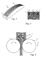
- Fig. 1 shows a test device in a perspective view.
- Fig. 2 shows a section through the test device.
- Fig. 3 schematically shows a roller crusher.
- Fig. 4 shows a test arrangement including the test device.
- Fig. 5 shows the test arrangement of Fig. 4 in another position.
- Fig. 6 illustrates a method according to embodiments of the invention.
Detailed description of preferred embodiments of the invention
-
A test device 1 for a roller crusher comprises a number of pins 2, which extend a distance 3 from a crushing surface 4. In this context it may be noted that the test device 1 is equally useful for a roller crusher or a roller grinder or for any type of equipment where materials are crushed, ground or pulverized between two rolls rotating in opposite directions towards each other. The test device may be mounted as part of the crushing surface in a conventional roller crusher or grinder, or it may be part of a specially designed test equipment as is illustrated in Figs 4-5.
-
At least one of the pins 2 is connected to a strain gauge 5, which is arranged to sense the amount of force exerted on the pin or pins 2' which are connected to strain gauges 5.
-
As noted above, the crushing surface 4 may be the crushing surface of a crushing roll 6 in a roller crusher equipment 7. Such a crushing roll is rotatably mounted opposite a similar crushing roll 8 which is arranged to rotate in the opposite direction so that materials M are crushed or pulverized between the rolls and against each other as the materials M enter a gap 9 between the rolls 6 and 8. As an option, two test devices could be used, one on each roll 6 and 8. The crushing rolls 6, 8 may be part of a roller crusher equipment used as a test arrangement or used for operational crushing or grinding.
-
It may be noted that the pins 2 are made of a material such as steel which is harder than the crushing surface 4, which can be made of steel or other metallic or ceramic material. In a roller crusher used for production purposes the pins are placed over the entire crushing surface and then strengthen the crushing surface in two ways. To start with, the materials that are crushed against the crushing surface primarily bear against the pins and not the crushing surface, which means that the crushing surface is not as subjected to the wear and tear of the materials. Secondly, smaller particles in the materials being crushed will get caught between the pins and create a protecting layer of materials on the crushing surface.
-
The test device can also be part of a sector shaped roll part 10 which is used for test purposes in a specially designed test equipment 11 which is shown in Fig. 4 and 5. The crushing surface 4 is then the crushing surface of the sector shaped roll part 10. This sector shaped roll part 10 is rotatably mounted opposite a similar sector shaped roll part 12 which is rotatable in an opposite direction. The sector shaped roll parts 10 and 12 are arranged to rotate from a first position as shown in Fig. 4, to a second position as shown in Fig. 5, as materials M are fed into the gap 9 and crushed between the roll parts 10 and 12 and against each other during a test session.
-
The strain gauges 5 which are connected to the pins 2' will then, during that test session, sense the force which is exerted upon the pins 2' by the materials M. As an option, two test devices could be used, one on each sector shaped roll part 10 and 12.
-
Regardless of whether the test device is part of a crushing roll or a sector shaped roll part, the output from the strain gauges 5 can be sent to a data logger which stores the measured strains. These strain values translate into pressure or force values for the pins 2' and the pressure or force values are then analyzed and used for determining a number of parameters describing the interaction between the test device 1 and the materials M being crushed. This information can then be used for classifying the materials M and for efficiently designing a roller crusher equipment for those particular materials, e.g. when selecting a size and power of a motor driving the rotation. The sensed pressure may also be used when determining a design and/or pin material of pins when designing a roll.
-
The number of pins 2' connected to strain gauges 5 as well as the positioning of these among the pins 2 in total may be decided based on the axial position on the roll. The materials M being crushed behave differently at the centre of the roll, at the ends of the roll and in positions there between. The influence of feed, distribution, edge effects etc. may thus be studied.
-
Another option is to arrange a number of pins 2' connected to strain gauges along a line extending across the width of the rolls or roll parts, or in other words transverse to the rotational direction of the rolls. The pressure sensed at these pins may then be used to analyze the pressure changes over the width of the rolls, e.g. in order to analyze the so called "bathtub effect" which is well known in the art. This information may in turn be useful when selecting end plates for the rolls.
-
A sensor (not shown) may in addition be arranged for sensing the rotational position of the rolls or roll parts, and the output from this sensor may be combined with the information from the strain gauges in order to determine pressure curves showing how the pressure on the pins 2' changes as the roll 6 or roll part 10 is rotated.
-
Fig. 6 illustrates a method according to embodiments of the invention. In step 13, pins are provided in a crushing surface of either a sector shaped roll part in a test equipment for a roller crusher, or in a crushing roll of a roller crusher.
-
In step 14 at least one of the pins is connected to a strain gauge. In step 15 materials are crushed against the crushing surface, as the materials are fed into a gap between two crushing rolls or between two sector shaped roll parts in a test equipment.
-
Finally, in step 16, the pressure exerted on the at least one pin which is connected to the strain gauge is sensed by the strain gauge. The sensed or measured strain values can then be saved by a data logging device and be used for analyzing the interaction between the materials and the test device. The strain values may also, as mentioned above, be combined with information on the rotational position of the rolls or roll parts.