EP2657133A2 - Aircraft ice protection system with operation optimization based on ice-detection input - Google Patents
Aircraft ice protection system with operation optimization based on ice-detection input Download PDFInfo
- Publication number
- EP2657133A2 EP2657133A2 EP13165516.9A EP13165516A EP2657133A2 EP 2657133 A2 EP2657133 A2 EP 2657133A2 EP 13165516 A EP13165516 A EP 13165516A EP 2657133 A2 EP2657133 A2 EP 2657133A2
- Authority
- EP
- European Patent Office
- Prior art keywords
- ice
- ice protection
- protection system
- set forth
- optimizer
- Prior art date
- Legal status (The legal status is an assumption and is not a legal conclusion. Google has not performed a legal analysis and makes no representation as to the accuracy of the status listed.)
- Ceased
Links
Images


Classifications
-
- B—PERFORMING OPERATIONS; TRANSPORTING
- B64—AIRCRAFT; AVIATION; COSMONAUTICS
- B64D—EQUIPMENT FOR FITTING IN OR TO AIRCRAFT; FLIGHT SUITS; PARACHUTES; ARRANGEMENTS OR MOUNTING OF POWER PLANTS OR PROPULSION TRANSMISSIONS IN AIRCRAFT
- B64D15/00—De-icing or preventing icing on exterior surfaces of aircraft
- B64D15/12—De-icing or preventing icing on exterior surfaces of aircraft by electric heating
-
- B—PERFORMING OPERATIONS; TRANSPORTING
- B64—AIRCRAFT; AVIATION; COSMONAUTICS
- B64D—EQUIPMENT FOR FITTING IN OR TO AIRCRAFT; FLIGHT SUITS; PARACHUTES; ARRANGEMENTS OR MOUNTING OF POWER PLANTS OR PROPULSION TRANSMISSIONS IN AIRCRAFT
- B64D15/00—De-icing or preventing icing on exterior surfaces of aircraft
- B64D15/20—Means for detecting icing or initiating de-icing
- B64D15/22—Automatic initiation by icing detector
Definitions
- An aircraft can encounter icing conditions during when it flies through a cloud containing supercooled droplets having nonzero liquid water contents (e.g ., up to 2.5 grams of water per cubic meter of air).
- nonzero liquid water contents e.g ., up to 2.5 grams of water per cubic meter of air.
- the most severe icing conditions will occur when the temperature is at its coldest (e.g ., approaching -30°C (-22° F)), the relevant speed is the fastest, and mean droplet size is relatively large ( e.g ., nearing 50 micrometers).
- An ice protection system must be designed to protect an aircraft from the most severe conditions.
- An ice protection system uses ice-detection input data (e.g., liquid water content, mean droplet size, etc.), optionally along with other inputs, to optimize operation to effectively and efficiently protect an aircraft in icing conditions.
- ice-detection input data e.g., liquid water content, mean droplet size, etc.
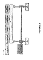
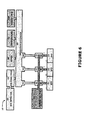
- Figures 1- 12 each show an ice protection system for protecting aircraft surfaces in icing conditions.
- the ice protection system 10 is adapted to protect an ice-susceptible region 11.
- the system 10 comprises an ice protection device 21 associated with the region 11, an onboard power source 30 with a supply line 31 to the ice protection device 21, and a controller 41 which controls power supply through the line 31.
- An optimizer 50 conveys switching instructions 51 to the controller 41, based at least on an ice detector 60 which provides ice-condition inputs 70 thereto.
- the optimizer 50 can receive additional inputs, such as an airspeed input 80, an ambient temperature input 90, and/or a flight input 100.
- the optimizer 50 is schematically shown in the drawings as separate entity from the controller 41, this need not be the case.
- the optimizer 50, the controller 41, and other system components can incorporated into or share installations.
- the optimizer 50 for example, can be an algorithm contained within a microprocessor integrated with controllers.
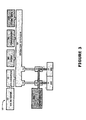
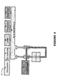
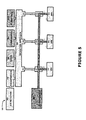
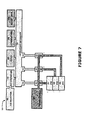
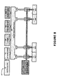
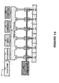
- FIGS 2-12 they each show an ice protection system 10 is adapted to protect at least two regions 11-12 (each having its own line 31-32, controller 41-42, and instructions 51-52), at least three regions 11-13 (each having its own line 31-33, controller 41-43, and instructions 51-53), at least four regions 11-14 (each having its own line 31-34, controller 41-44, and instructions 51-54), and/or at least six regions 11-16 (each having its own line 31-36, controller 41-46, and instructions 51-56).
- regions 11-12 each having its own line 31-32, controller 41-42, and instructions 51-52
- regions 11-13 each having its own line 31-33, controller 41-43, and instructions 51-53
- regions 11-14 each having its own line 31-34, controller 41-44, and instructions 51-54
- regions 11-16 each having its own line 31-36, controller 41-46, and instructions 51-56.
- the regions can be located remote from each other (see e.g ., Figures 2 , 5 , 8 ), in spanwise rows (see e.g ., Figures 3 , 6 , 8 , 9 , 10 , 11 , 12 ), and/or in chordwise columns (see e.g ., Figures 4 , 7 , 10 , 12 ).
- the ice protection devices 21-26 can each comprise a heating element which converts electric power into heat. If the ice protection devices 21-26 are of the electrothermal type, the source 30 can comprise an onboard source of AC or DC power and the controllers 41-46 can comprise electric switches, capacitors, pulsing circuitry, or other suitable components.
- the system 10 could additionally or alternatively employ other types of ice protection devices (e.g ., pneumatic thermal devices, electro-impulse systems, pneumatic boots, etc.) and thus additional or other power sources.
- the controllers 41-46 can be configured to simply turn the ice protection devices 21-26 on and off. In this case, operational optimization can be achieved by avoiding the activation of ice protection when such is not yet needed. Also, with particular reference to deicing scenarios, device activation can be coordinated with optimum ice thickness so that a deicing cycle is not wasted on an ice thickness well below that which can be tolerated by the aircraft surface. Alternatively, the controllers 41-46 can be adjust power-supply levels to the ice protection devices. This could be accomplished by adjusting the actual power supply levels, by modulation, and/or by adjusting deicing cycle increments. Generally, the more power levels available, the greater the potential for energy savings.
- the optimizer 50 can comprise a processor programmed with historical data, mathematical models, and/or developed algorithms allowing it to optimize the efficiency and effectiveness of ice protection.
- the optimizer 50 can take into consideration non-changing designs features of the respective regions (e.g . airfoil sharpness, ice collection efficiency, proximity to moving parts, etc.). Also, the optimizer 50 can look at the operation of related ice protection devices as a coordinated scheme.
- the ice detector 60 can comprise any suitable detecting technology capable of providing the relevant input 70.
- the detector 60 can comprise cloud-responsive heating elements (see e.g ., US20110288776 , US5140135 , US4980673 ), vibrating probes which change frequency with ice accretion (see e.g ., US7104502 , US6759962 , US6847903 , US4611492 ), optical mechanisms (see e.g ., US8144325 , US 6069565 ), temperature-maintaining resistors (see e.g ., US8037750 ), clog-with-ice conduits (see e.g ., US798464 , US7845221 ), ice-thickness-changes-impedance arrangements of electrodes (see e.g ., US6759962 , US5955887 ), acoustic channels (see e.g ., US5922958
- a suitable candidate for the ice detector 60 could be an optical ice detector (OID which analyzes circularly polarized light scattered from airborne cloud particles.
- OID optical ice detector
- Such a detector could include a laser apparatus configured to direct a light signal into a cloud, a lens component configured to collect echo signals from a cloud caused by the light signal directed into the cloud, a beam splitter component configured to redirect signals received and passing through the lens component into at least first and second paths and a droplet detector to receive the redirected signals.
- the droplet detector could include a first signal detector component configured to perform a first color measurement on the first redirected signal, and a second signal detector component configured to perform a second color measurement on the second redirected signal.
- the droplet detector is configured to use the first and second color measurements to determine liquid water content and droplet diameter distribution for the cloud. (See e.g ., US 8338785 .)
- the ice detector 60 detects a non-temperature parameter such as liquid water content (LWC), ice water content (IWC), total water content (TWC), mean drop size, median volumetric drop (MDV), and/or ice thickness (THICK).
- a non-temperature parameter such as liquid water content (LWC), ice water content (IWC), total water content (TWC), mean drop size, median volumetric drop (MDV), and/or ice thickness (THICK).
- LWC liquid water content
- IWC ice water content
- TWC total water content
- MDV median volumetric drop
- THICK ice thickness
- the speed input 80 is a non-temperature input which correlates to the impingement speed encountered by droplets on route to the aircraft surface. This input 80, however, need not be a precise measurement of the airspeed, but can be or use other related velocities such as aircraft speed.
- the temperature input 90 is an input corresponding to ambient temperature conditions, not the temperature of the ice protection device or associated region.
- one advantage of the ice protection system 10 is that it can eliminate the need for surface temperature devices, and thus the corresponding wiring.
- the ice protection system can be characterized by the absence of surface temperatures and/or their input being used to by the optimizer 50 to determine optimum ice protection parameters. That being said, an ice protection system including surface temperature sensors is possible and contemplated.
- the input 100 comprises a non-temperature input relating to overall flight.
- This input 100 can comprise, for example, aircraft altitude (ALT), aircraft speed (SPEED), angle of attack (AOA), flight phase (PHASE), weight on wheels (WOW), and/or the position of movable parts (PART).
- ALT aircraft altitude
- SPEED aircraft speed
- AOA angle of attack
- PHASE flight phase
- WOW weight on wheels
- PART position of movable parts
- the ice protection device in a fully-evaporative anti-ice mode, is expected to fully evaporate all impinging water by heating the region 11 to a relatively high temperature.
- This mode of ice protection is extremely power-intensive and has been traditionally reserved only for critical aircraft areas where at wet runback and/or ice injection cannot be tolerated.
- the associated ice protection device 21 must be designed to evaporate impingement in the most severe ice conditions. With the ice protection system 10, power to the evaporative anti-icing device 21 can be reduced when icing conditions are not at their worst. As severe ice conditions often account for less than 5% of all icing conditions during a flight, this would result in substantial power savings.
- an anti-icing region can be operated in a fully-evaporative anti-ice mode or a less-power-intensive "running wet” mode depending upon its neighboring deicing regions. If regions 11-13 are arranged in chordwise column, an anti-icing region 12 can be sandwiched between two deicing regions 11 and 13. If these regions are cold enough to cause refreeze, a fully-evaporative mode may not be necessary and the ice protection device 12 can be operated in a running wet mode.
- the ice protection system 10 can include an ice protection device 21 reserved solely for use when the input 70 is indicative of supercooled large droplets (SLDs).
- This ice protection device 21 could be located chordwise aft of most routine devices, in traditionally non-iced areas believed to be plagued by the super large droplets. If the ice detector 60 is an optical detector, it could directly measure the presence of SLD within the icing cloud.
- the "on" threshold for the different regions may vary along the row, probably decreasing in the outboard direction.
- the ice protection system 10 uses ice-detection data to optimize operation.
- the system 10 the ice protection devices 21-26, the power source 30, the supply lines 31-36, the controllers 41-46, the optimizer 50, the instructions 51-52, the ice detector 60, the ice condition input 70, the temperature input 80, the speed input 90, and/or the flight-info input 100 have been shown and described with respect to certain embodiments, obvious and equivalent alterations and modifications will occur to others skilled in the art upon the reading and understanding of this specification.
Abstract
Description
- An aircraft can encounter icing conditions during when it flies through a cloud containing supercooled droplets having nonzero liquid water contents (e.g., up to 2.5 grams of water per cubic meter of air). As a general rule, for a thermal ice protection system, the most severe icing conditions will occur when the temperature is at its coldest (e.g., approaching -30°C (-22° F)), the relevant speed is the fastest, and mean droplet size is relatively large (e.g., nearing 50 micrometers). An ice protection system must be designed to protect an aircraft from the most severe conditions.
- An ice protection system is provided which uses ice-detection input data (e.g., liquid water content, mean droplet size, etc.), optionally along with other inputs, to optimize operation to effectively and efficiently protect an aircraft in icing conditions.
-
Figures 1- 12 each show an ice protection system for protecting aircraft surfaces in icing conditions. - Referring to
Figure 1 , theice protection system 10 is adapted to protect an ice-susceptible region 11. Thesystem 10 comprises anice protection device 21 associated with theregion 11, anonboard power source 30 with asupply line 31 to theice protection device 21, and acontroller 41 which controls power supply through theline 31. Anoptimizer 50conveys switching instructions 51 to thecontroller 41, based at least on anice detector 60 which provides ice-condition inputs 70 thereto. Theoptimizer 50 can receive additional inputs, such as anairspeed input 80, anambient temperature input 90, and/or aflight input 100. - Although the
optimizer 50 is schematically shown in the drawings as separate entity from thecontroller 41, this need not be the case. Theoptimizer 50, thecontroller 41, and other system components (including the other controllers 42-46 introduced below) can incorporated into or share installations. Theoptimizer 50, for example, can be an algorithm contained within a microprocessor integrated with controllers. - Referring to
Figures 2-12 , they each show anice protection system 10 is adapted to protect at least two regions 11-12 (each having its own line 31-32, controller 41-42, and instructions 51-52), at least three regions 11-13 (each having its own line 31-33, controller 41-43, and instructions 51-53), at least four regions 11-14 (each having its own line 31-34, controller 41-44, and instructions 51-54), and/or at least six regions 11-16 (each having its own line 31-36, controller 41-46, and instructions 51-56). The regions can be located remote from each other (see e.g.,Figures 2 ,5 ,8 ), in spanwise rows (see e.g.,Figures 3 ,6 ,8 ,9 ,10 ,11 ,12 ), and/or in chordwise columns (see e.g.,Figures 4 ,7 ,10 ,12 ). - The ice protection devices 21-26 can each comprise a heating element which converts electric power into heat. If the ice protection devices 21-26 are of the electrothermal type, the
source 30 can comprise an onboard source of AC or DC power and the controllers 41-46 can comprise electric switches, capacitors, pulsing circuitry, or other suitable components. Thesystem 10 could additionally or alternatively employ other types of ice protection devices (e.g., pneumatic thermal devices, electro-impulse systems, pneumatic boots, etc.) and thus additional or other power sources. - The controllers 41-46 can be configured to simply turn the ice protection devices 21-26 on and off. In this case, operational optimization can be achieved by avoiding the activation of ice protection when such is not yet needed. Also, with particular reference to deicing scenarios, device activation can be coordinated with optimum ice thickness so that a deicing cycle is not wasted on an ice thickness well below that which can be tolerated by the aircraft surface. Alternatively, the controllers 41-46 can be adjust power-supply levels to the ice protection devices. This could be accomplished by adjusting the actual power supply levels, by modulation, and/or by adjusting deicing cycle increments. Generally, the more power levels available, the greater the potential for energy savings.
- The
optimizer 50 can comprise a processor programmed with historical data, mathematical models, and/or developed algorithms allowing it to optimize the efficiency and effectiveness of ice protection. In addition to the data dynamically input during operation of theice protection system 10, theoptimizer 50 can take into consideration non-changing designs features of the respective regions (e.g. airfoil sharpness, ice collection efficiency, proximity to moving parts, etc.). Also, theoptimizer 50 can look at the operation of related ice protection devices as a coordinated scheme. - The
ice detector 60 can comprise any suitable detecting technology capable of providing therelevant input 70. For example, thedetector 60 can comprise cloud-responsive heating elements (see e.g.,US20110288776 ,US5140135 ,US4980673 ), vibrating probes which change frequency with ice accretion (see e.g.,US7104502 ,US6759962 ,US6847903 ,US4611492 ), optical mechanisms (see e.g.,US8144325 ,US 6069565 ), temperature-maintaining resistors (see e.g.,US8037750 ), clog-with-ice conduits (see e.g.,US798464 ,US7845221 ), ice-thickness-changes-impedance arrangements of electrodes (see e.g.,US6759962 ,US5955887 ), acoustic channels (see e.g.,US5922958 ) and/or piezoelectric film arrays (see e.g.,US5206806 ). - A suitable candidate for the
ice detector 60 could be an optical ice detector (OID which analyzes circularly polarized light scattered from airborne cloud particles. Such a detector could include a laser apparatus configured to direct a light signal into a cloud, a lens component configured to collect echo signals from a cloud caused by the light signal directed into the cloud, a beam splitter component configured to redirect signals received and passing through the lens component into at least first and second paths and a droplet detector to receive the redirected signals. The droplet detector could include a first signal detector component configured to perform a first color measurement on the first redirected signal, and a second signal detector component configured to perform a second color measurement on the second redirected signal. The droplet detector is configured to use the first and second color measurements to determine liquid water content and droplet diameter distribution for the cloud. (See e.g.,US 8338785 .) - The
ice detector 60 detects a non-temperature parameter such as liquid water content (LWC), ice water content (IWC), total water content (TWC), mean drop size, median volumetric drop (MDV), and/or ice thickness (THICK). The significant non-temperature parameter is detected, not estimated, predicted, or otherwise calculated solely from temperature data. Temperature data may be used, however, in conjunction with this parameter to produce theinput 70. - The
speed input 80 is a non-temperature input which correlates to the impingement speed encountered by droplets on route to the aircraft surface. Thisinput 80, however, need not be a precise measurement of the airspeed, but can be or use other related velocities such as aircraft speed. - The
temperature input 90 is an input corresponding to ambient temperature conditions, not the temperature of the ice protection device or associated region. In fact, one advantage of theice protection system 10 is that it can eliminate the need for surface temperature devices, and thus the corresponding wiring. - Thus, the ice protection system can be characterized by the absence of surface temperatures and/or their input being used to by the
optimizer 50 to determine optimum ice protection parameters. That being said, an ice protection system including surface temperature sensors is possible and contemplated. - The
input 100 comprises a non-temperature input relating to overall flight. Thisinput 100 can comprise, for example, aircraft altitude (ALT), aircraft speed (SPEED), angle of attack (AOA), flight phase (PHASE), weight on wheels (WOW), and/or the position of movable parts (PART). - By way of example, in a fully-evaporative anti-ice mode, the ice protection device is expected to fully evaporate all impinging water by heating the
region 11 to a relatively high temperature. This mode of ice protection is extremely power-intensive and has been traditionally reserved only for critical aircraft areas where at wet runback and/or ice injection cannot be tolerated. Clearly the associatedice protection device 21 must be designed to evaporate impingement in the most severe ice conditions. With theice protection system 10, power to the evaporativeanti-icing device 21 can be reduced when icing conditions are not at their worst. As severe ice conditions often account for less than 5% of all icing conditions during a flight, this would result in substantial power savings. - By way of another example, an anti-icing region can be operated in a fully-evaporative anti-ice mode or a less-power-intensive "running wet" mode depending upon its neighboring deicing regions. If regions 11-13 are arranged in chordwise column, an
anti-icing region 12 can be sandwiched between twodeicing regions ice protection device 12 can be operated in a running wet mode. - By way of another example, the
ice protection system 10 can include anice protection device 21 reserved solely for use when theinput 70 is indicative of supercooled large droplets (SLDs). Thisice protection device 21 could be located chordwise aft of most routine devices, in traditionally non-iced areas believed to be plagued by the super large droplets. If theice detector 60 is an optical detector, it could directly measure the presence of SLD within the icing cloud. - By way of a further example, when regions 11-16 are arranged in a spanwise row, the "on" threshold for the different regions may vary along the row, probably decreasing in the outboard direction.
- One may now appreciate the
ice protection system 10 uses ice-detection data to optimize operation. Although thesystem 10, the ice protection devices 21-26, thepower source 30, the supply lines 31-36, the controllers 41-46, theoptimizer 50, the instructions 51-52, theice detector 60, theice condition input 70, thetemperature input 80, thespeed input 90, and/or the flight-info input 100 have been shown and described with respect to certain embodiments, obvious and equivalent alterations and modifications will occur to others skilled in the art upon the reading and understanding of this specification.
Claims (15)
- An ice protection system (10) adapted to protect at least one ice-susceptible region (11-16) of an aircraft, said system (10) comprising:an ice protection device (21-26) associated with each region (11-16);an onboard power source (30) and a supply line (31-36) to each ice protection device (21-26);a controller (41-46) for each ice protector (21-26) which controls power supply through each supply line (31-36);an optimizer (50) which conveys operation-optimizing instructions (51-56) to each controller (41-46); andan ice detector (60) which provides an ice-condition input (70), this ice-condition input (70) being used to generate the operation-optimizing instructions (51-56).
- An ice protection system (10) as set forth in claim 1, wherein the optimizer (50) uses the ice-condition input (70) to determine an optimum power level and conveys this power level in the instruction (51-56) to an ice protection device (21-26), and wherein this ice protection device (21-26) operates in a fully-evaporative anti-icing mode.
- An ice protection system (10) as set forth in claim 1 or 2, adapted to protect neighboring ice-susceptible regions (11-13) of the aircraft, wherein the optimizer (50) considers the status of neighboring ice protection devices (21, 23) when determining an optimum power level for the other ice protection device (22).
- An ice protection system (10) as set forth in any preceding claim, wherein the ice protection device (21) operates in a fully evaporative anti-icing mode when the optimizer (50) determines that runback will not refreeze on the neighboring region (11, 13) and operates in a running wet anti-icing mode when the optimizer (50) determines that runback will refreeze on the neighboring region (11, 13).
- An ice protection system (10) as set forth in any preceding claim, wherein the ice detector (60) detects super large droplets (SLDs) and provides a corresponding input (70); and wherein the optimizer (50) only turns on an ice protection device (21-26) when the input (70) is indicative of super large droplets (SLDs).
- An ice protection system (10) as set forth in any preceding claim, adapted to protect a plurality of ice-susceptible regions (11-16) of an aircraft, wherein the optimizer (50) uses the ice-condition input (70) to determine icing severity and compares this determination to threshold to produce instructions (51-56); and wherein the thresholds vary among the ice protection devices (21-26).
- An ice protection system (10) as set forth in any preceding claim, wherein the ice protection devices (21-26) are arranged in a spanwise row and wherein the thresholds decrease in the outboard direction.
- An ice protection system (10) as set forth in any of the preceding claims, characterized by the absence of temperature sensors on the ice-susceptible region (11).
- An ice protection system (10) as set forth in any of the preceding claims, characterized by the optimizer (50) not using input from surface temperature sensors to generate the operation-optimizing instructions (51).
- An ice protection system (10) as set forth in any of the preceding claims, wherein the ice detector (60) is an optical ice detector which analyzes circularly polarized light scattered from airborne cloud particles.
- An ice protection system (10) as set forth in any of the preceding claims, wherein the optimizer (50) comprises an algorithm contained within a microprocessor installed in the controllers (41-46).
- An ice protection system (10) as set forth in any of the preceding claims, wherein each ice protection device (21-26) comprises a heating element which converts electric power into heat.
- An ice protection system (10) as set forth in any of the preceding claims, wherein the source (30) comprises an onboard source of electric power.
- An ice protection system (10) as set forth in any of the preceding claims, wherein the ice detector (60) detects liquid water content (LWC).
- An ice protection system (10) as set forth in any of the preceding claims, wherein the ice detector (60) detects ice water content (IWC) and/or total water content (TWC).
Applications Claiming Priority (2)
| Application Number | Priority Date | Filing Date | Title |
|---|---|---|---|
| US201261639366P | 2012-04-27 | 2012-04-27 | |
| US201361800310P | 2013-03-15 | 2013-03-15 |
Publications (2)
| Publication Number | Publication Date |
|---|---|
| EP2657133A2 true EP2657133A2 (en) | 2013-10-30 |
| EP2657133A3 EP2657133A3 (en) | 2016-08-03 |
Family
ID=48428328
Family Applications (1)
| Application Number | Title | Priority Date | Filing Date |
|---|---|---|---|
| EP13165516.9A Ceased EP2657133A3 (en) | 2012-04-27 | 2013-04-26 | Aircraft ice protection system with operation optimization based on ice-detection input |
Country Status (5)
| Country | Link |
|---|---|
| US (1) | US9555894B2 (en) |
| EP (1) | EP2657133A3 (en) |
| CN (1) | CN103448912B (en) |
| BR (1) | BR102013010356A2 (en) |
| CA (1) | CA2814061C (en) |
Cited By (2)
| Publication number | Priority date | Publication date | Assignee | Title |
|---|---|---|---|---|
| EP2979980A1 (en) | 2014-07-29 | 2016-02-03 | Airbus Helicopters | Method and device for detecting when an aircraft flies in icing conditions |
| EP3195692B1 (en) * | 2014-08-22 | 2020-09-02 | Bombardier Inc. | Apparatus and method for controlled heating of a vehicle window |
Families Citing this family (19)
| Publication number | Priority date | Publication date | Assignee | Title |
|---|---|---|---|---|
| GB2511343B (en) * | 2013-02-28 | 2015-07-22 | Gkn Aerospace Services Ltd | Ice protection system |
| US10207810B2 (en) | 2016-03-21 | 2019-02-19 | Rosemount Aerospace Inc. | Optically detecting cloud metrics using sampled analog measurements of light reflection |
| US20170283077A1 (en) | 2016-04-01 | 2017-10-05 | Goodrich Corporation | Pneumatic de-icer with sensor for supercooled large droplet icing detection |
| US11137519B2 (en) * | 2016-07-21 | 2021-10-05 | Rosemount Aerospace Inc. | Multi-fiber optical sensor for icing |
| US10392117B2 (en) * | 2016-09-23 | 2019-08-27 | General Electric Company | Icing condition detection using instantaneous humidity sensing |
| US10708979B2 (en) | 2016-10-07 | 2020-07-07 | De-Ice Technologies | Heating a bulk medium |
| US10429511B2 (en) * | 2017-05-04 | 2019-10-01 | The Boeing Company | Light detection and ranging (LIDAR) ice detection system |
| US20190039742A1 (en) * | 2017-08-01 | 2019-02-07 | Honeywell International Inc. | Managing response to icing threat |
| US10759517B2 (en) * | 2017-12-12 | 2020-09-01 | The Boeing Company | System and method for modifying the location of water impingement limits on an airfoil |
| US10435161B1 (en) * | 2018-05-02 | 2019-10-08 | Rosemount Aerospace Inc. | Surface sensing for droplet size differentiation |
| US20210300571A1 (en) * | 2020-03-24 | 2021-09-30 | Goodrich Corporation | Heater power modulation based on outside air temperature and aircraft velocity |
| US11685534B2 (en) | 2020-08-10 | 2023-06-27 | Lockheed Martin Corporation | System and method for determining the real-time effect of ice accumulation on aircraft surfaces on angle of attack during flight |
| CN113109378B (en) * | 2021-04-06 | 2022-09-27 | 山东省鲁南地质工程勘察院(山东省地勘局第二地质大队) | Steep rock surface water vapor condensation monitoring method |
| US20220396361A1 (en) * | 2021-06-10 | 2022-12-15 | Goodrich Corporation | Mechanical ice protection system for aerodynamic surfaces |
| CN113533414B (en) * | 2021-07-20 | 2022-05-06 | 北京航空航天大学 | Vertical high-speed ejection device for ice crystal impact test |
| US20230104595A1 (en) * | 2021-10-06 | 2023-04-06 | Goodrich Corporation | Control of electric pump-driven deicer |
| CN114476083A (en) * | 2021-12-31 | 2022-05-13 | 中国航空工业集团公司西安飞机设计研究所 | Shape-preserving type icing detection system and method |
| US11912419B2 (en) | 2022-01-21 | 2024-02-27 | Honeywell International Inc. | Ice protection modulation with atmospheric conditions |
| US20230312111A1 (en) * | 2022-04-05 | 2023-10-05 | Goodrich Corporation | Systems and methods for an ice runback control zone in an electrothermal ice protection system |
Citations (16)
| Publication number | Priority date | Publication date | Assignee | Title |
|---|---|---|---|---|
| US798464A (en) | 1904-08-20 | 1905-08-29 | Charles H Sprague | Support for prolapsed uterus. |
| US4611492A (en) | 1984-05-03 | 1986-09-16 | Rosemount Inc. | Membrane type non-intrusive ice detector |
| US4980673A (en) | 1987-06-10 | 1990-12-25 | Rosemount Inc. | Ice detector circuit |
| US5140135A (en) | 1989-09-21 | 1992-08-18 | Rosemount Inc. | Adaptive ice detector circuit |
| US5206806A (en) | 1989-01-10 | 1993-04-27 | Gerardi Joseph J | Smart skin ice detection and de-icing system |
| US5922958A (en) | 1996-05-22 | 1999-07-13 | Rosemount Aerospace Inc. | Acoustic channel for contaminant detection on a surface |
| US5955887A (en) | 1995-12-22 | 1999-09-21 | The B. F. Goodrich Company | Impedance type ice detector |
| US6069565A (en) | 1992-10-20 | 2000-05-30 | Rosemount Aerospace Inc. | System for detecting ice or snow on surface which specularly reflects light |
| US6759962B2 (en) | 2001-04-25 | 2004-07-06 | Rosemount Aerospace Inc. | Inflight ice detector to distinguish supercooled large droplet (SLD) icing |
| US6847903B2 (en) | 2000-08-18 | 2005-01-25 | Rosemount Aerospace Inc. | Liquid water content measurement apparatus and method |
| US7104502B2 (en) | 2004-03-31 | 2006-09-12 | Rosemount Aerospace Inc. | Ice detector for improved ice detection at near freezing condition |
| US7845221B2 (en) | 2006-09-25 | 2010-12-07 | Rosemount Aerospace, Inc. | Detecting ice particles |
| US8037750B2 (en) | 2009-10-29 | 2011-10-18 | Rosemount Aerospace, Inc. | Impending icing probe with thermal isolation pedestal |
| US20110288776A1 (en) | 2006-01-11 | 2011-11-24 | Science Engineering Associates, Inc. | Cloud water characterization system |
| US8144325B2 (en) | 2009-07-23 | 2012-03-27 | Rosemount Aerospace, Inc. | In-flight multiple field of view detector for supercooled airborne water droplets |
| US8338785B2 (en) | 2011-04-29 | 2012-12-25 | Rosemount Aerospace Inc. | Apparatus and method for detecting aircraft icing conditions |
Family Cites Families (16)
| Publication number | Priority date | Publication date | Assignee | Title |
|---|---|---|---|---|
| US5322246A (en) * | 1991-08-12 | 1994-06-21 | Mcdonnell Douglas Corporation | Ice prevention device for airfoils |
| US6237874B1 (en) * | 1997-09-22 | 2001-05-29 | Northcoast Technologies | Zoned aircraft de-icing system and method |
| EP1396425A1 (en) | 2003-03-10 | 2004-03-10 | Auxitrol SA | Large spectrum icing conditions detector |
| GB2410481B (en) * | 2004-01-30 | 2008-06-04 | Ultra Electronics Ltd | Modular aircraft control system and method |
| GB2447374B (en) | 2004-01-30 | 2008-10-29 | Ultra Electronics Ltd | Modular aircraft power control system and method |
| US7124983B2 (en) * | 2004-08-20 | 2006-10-24 | Honeywell International, Inc. | Hybrid electrical ice protection system and method including an energy saving mode |
| US7312713B2 (en) * | 2004-12-17 | 2007-12-25 | Research Foundation Of The City University Of New York | Methods and systems for detection of ice formation on surfaces |
| US7828247B2 (en) | 2006-01-12 | 2010-11-09 | Safe Flight Instrument Corporation | Automatic recycling ice detector |
| US7370525B1 (en) * | 2006-10-31 | 2008-05-13 | Swan International Sensors Pty. Ltd. | Inflight ice detection system |
| US8265805B2 (en) | 2007-11-11 | 2012-09-11 | The Boeing Company | Method and apparatus for detecting icing conditions for an aircraft |
| EP2202151B1 (en) * | 2008-11-17 | 2016-09-14 | Goodrich Corporation | Aircraft with an ice protection system |
| CN201359467Y (en) * | 2008-12-23 | 2009-12-09 | 中国船舶重工集团公司第七一三研究所 | Anti-icing control device |
| CN101590914A (en) | 2009-07-02 | 2009-12-02 | 北京航空航天大学 | A kind of anti-icing and deicing device for flight vehicle |
| CN101695959B (en) | 2009-10-22 | 2012-01-11 | 北京航空航天大学 | Ice preventing and removing device for helicopter rotors |
| WO2013033654A1 (en) * | 2011-08-31 | 2013-03-07 | De Rochemont L Pierre | Fully integrated thermoelectric devices and their application to aerospace de-icing systems |
| US10513340B2 (en) * | 2012-08-02 | 2019-12-24 | Rosemount Aerospace Inc. | Rotor ice protection systems and methods |
-
2013
- 2013-04-26 BR BRBR102013010356-0A patent/BR102013010356A2/en not_active Application Discontinuation
- 2013-04-26 EP EP13165516.9A patent/EP2657133A3/en not_active Ceased
- 2013-04-26 CA CA2814061A patent/CA2814061C/en active Active
- 2013-04-26 US US13/871,207 patent/US9555894B2/en active Active
- 2013-04-27 CN CN201310240230.0A patent/CN103448912B/en active Active
Patent Citations (16)
| Publication number | Priority date | Publication date | Assignee | Title |
|---|---|---|---|---|
| US798464A (en) | 1904-08-20 | 1905-08-29 | Charles H Sprague | Support for prolapsed uterus. |
| US4611492A (en) | 1984-05-03 | 1986-09-16 | Rosemount Inc. | Membrane type non-intrusive ice detector |
| US4980673A (en) | 1987-06-10 | 1990-12-25 | Rosemount Inc. | Ice detector circuit |
| US5206806A (en) | 1989-01-10 | 1993-04-27 | Gerardi Joseph J | Smart skin ice detection and de-icing system |
| US5140135A (en) | 1989-09-21 | 1992-08-18 | Rosemount Inc. | Adaptive ice detector circuit |
| US6069565A (en) | 1992-10-20 | 2000-05-30 | Rosemount Aerospace Inc. | System for detecting ice or snow on surface which specularly reflects light |
| US5955887A (en) | 1995-12-22 | 1999-09-21 | The B. F. Goodrich Company | Impedance type ice detector |
| US5922958A (en) | 1996-05-22 | 1999-07-13 | Rosemount Aerospace Inc. | Acoustic channel for contaminant detection on a surface |
| US6847903B2 (en) | 2000-08-18 | 2005-01-25 | Rosemount Aerospace Inc. | Liquid water content measurement apparatus and method |
| US6759962B2 (en) | 2001-04-25 | 2004-07-06 | Rosemount Aerospace Inc. | Inflight ice detector to distinguish supercooled large droplet (SLD) icing |
| US7104502B2 (en) | 2004-03-31 | 2006-09-12 | Rosemount Aerospace Inc. | Ice detector for improved ice detection at near freezing condition |
| US20110288776A1 (en) | 2006-01-11 | 2011-11-24 | Science Engineering Associates, Inc. | Cloud water characterization system |
| US7845221B2 (en) | 2006-09-25 | 2010-12-07 | Rosemount Aerospace, Inc. | Detecting ice particles |
| US8144325B2 (en) | 2009-07-23 | 2012-03-27 | Rosemount Aerospace, Inc. | In-flight multiple field of view detector for supercooled airborne water droplets |
| US8037750B2 (en) | 2009-10-29 | 2011-10-18 | Rosemount Aerospace, Inc. | Impending icing probe with thermal isolation pedestal |
| US8338785B2 (en) | 2011-04-29 | 2012-12-25 | Rosemount Aerospace Inc. | Apparatus and method for detecting aircraft icing conditions |
Cited By (3)
| Publication number | Priority date | Publication date | Assignee | Title |
|---|---|---|---|---|
| EP2979980A1 (en) | 2014-07-29 | 2016-02-03 | Airbus Helicopters | Method and device for detecting when an aircraft flies in icing conditions |
| US9666051B2 (en) | 2014-07-29 | 2017-05-30 | Airbus Helicopters | Method and a device for detecting icing at an air inlet of a turboshaft engine |
| EP3195692B1 (en) * | 2014-08-22 | 2020-09-02 | Bombardier Inc. | Apparatus and method for controlled heating of a vehicle window |
Also Published As
| Publication number | Publication date |
|---|---|
| BR102013010356A2 (en) | 2015-06-30 |
| US9555894B2 (en) | 2017-01-31 |
| US20130284856A1 (en) | 2013-10-31 |
| CA2814061C (en) | 2018-01-16 |
| CN103448912A (en) | 2013-12-18 |
| CN103448912B (en) | 2017-10-31 |
| EP2657133A3 (en) | 2016-08-03 |
| CA2814061A1 (en) | 2013-10-27 |
Similar Documents
| Publication | Publication Date | Title |
|---|---|---|
| CA2814061C (en) | Aircraft ice protection optimization based on ice-detection input | |
| EP2943404B1 (en) | Apparatus and method for detecting water or ice | |
| EP2774851B1 (en) | Automated water drop measurement and ice detection system | |
| EP2870435B1 (en) | Cloud ice detector | |
| EP3228543B1 (en) | Ice detection system and method | |
| EP2163475B1 (en) | Propeller deicing system | |
| EP2202151B1 (en) | Aircraft with an ice protection system | |
| US9352841B2 (en) | Virtual ice accretion meter display | |
| CN205203396U (en) | Aircraft engine nacelle steam anti -icing system | |
| EP4101767A1 (en) | Mechanical ice protection system for aerodynamic surfaces | |
| US20220411079A1 (en) | Apparatus and method for detecting water or ice | |
| CA2822630C (en) | Ice protection system | |
| US20230249834A1 (en) | Mechanical ice protection system for aerodynamic surfaces | |
| KR102315288B1 (en) | Anti-icing or de-icing system for aircraft wing and method using the same | |
| EP3650349A1 (en) | De-icing system and method | |
| Cook | Maximum Temperature for Ice Accumulation Calculations |
Legal Events
| Date | Code | Title | Description |
|---|---|---|---|
| PUAI | Public reference made under article 153(3) epc to a published international application that has entered the european phase |
Free format text: ORIGINAL CODE: 0009012 |
|
| AK | Designated contracting states |
Kind code of ref document: A2 Designated state(s): AL AT BE BG CH CY CZ DE DK EE ES FI FR GB GR HR HU IE IS IT LI LT LU LV MC MK MT NL NO PL PT RO RS SE SI SK SM TR |
|
| AX | Request for extension of the european patent |
Extension state: BA ME |
|
| PUAL | Search report despatched |
Free format text: ORIGINAL CODE: 0009013 |
|
| AK | Designated contracting states |
Kind code of ref document: A3 Designated state(s): AL AT BE BG CH CY CZ DE DK EE ES FI FR GB GR HR HU IE IS IT LI LT LU LV MC MK MT NL NO PL PT RO RS SE SI SK SM TR |
|
| AX | Request for extension of the european patent |
Extension state: BA ME |
|
| RIC1 | Information provided on ipc code assigned before grant |
Ipc: B64D 15/12 20060101AFI20160627BHEP |
|
| STAA | Information on the status of an ep patent application or granted ep patent |
Free format text: STATUS: REQUEST FOR EXAMINATION WAS MADE |
|
| 17P | Request for examination filed |
Effective date: 20170201 |
|
| RBV | Designated contracting states (corrected) |
Designated state(s): AL AT BE BG CH CY CZ DE DK EE ES FI FR GB GR HR HU IE IS IT LI LT LU LV MC MK MT NL NO PL PT RO RS SE SI SK SM TR |
|
| STAA | Information on the status of an ep patent application or granted ep patent |
Free format text: STATUS: EXAMINATION IS IN PROGRESS |
|
| 17Q | First examination report despatched |
Effective date: 20180523 |
|
| STAA | Information on the status of an ep patent application or granted ep patent |
Free format text: STATUS: EXAMINATION IS IN PROGRESS |
|
| APBK | Appeal reference recorded |
Free format text: ORIGINAL CODE: EPIDOSNREFNE |
|
| APBN | Date of receipt of notice of appeal recorded |
Free format text: ORIGINAL CODE: EPIDOSNNOA2E |
|
| APBR | Date of receipt of statement of grounds of appeal recorded |
Free format text: ORIGINAL CODE: EPIDOSNNOA3E |
|
| APAF | Appeal reference modified |
Free format text: ORIGINAL CODE: EPIDOSCREFNE |
|
| APBT | Appeal procedure closed |
Free format text: ORIGINAL CODE: EPIDOSNNOA9E |
|
| STAA | Information on the status of an ep patent application or granted ep patent |
Free format text: STATUS: THE APPLICATION HAS BEEN REFUSED |
|
| 18R | Application refused |
Effective date: 20220801 |