EP2666403A1 - Endoscope system and processor device thereof, and image producing method - Google Patents
Endoscope system and processor device thereof, and image producing method Download PDFInfo
- Publication number
- EP2666403A1 EP2666403A1 EP13166229.8A EP13166229A EP2666403A1 EP 2666403 A1 EP2666403 A1 EP 2666403A1 EP 13166229 A EP13166229 A EP 13166229A EP 2666403 A1 EP2666403 A1 EP 2666403A1
- Authority
- EP
- European Patent Office
- Prior art keywords
- vessel
- wavelength
- contrast
- vessel pattern
- image
- Prior art date
- Legal status (The legal status is an assumption and is not a legal conclusion. Google has not performed a legal analysis and makes no representation as to the accuracy of the status listed.)
- Granted
Links
Images


Classifications
-
- A—HUMAN NECESSITIES
- A61—MEDICAL OR VETERINARY SCIENCE; HYGIENE
- A61B—DIAGNOSIS; SURGERY; IDENTIFICATION
- A61B1/00—Instruments for performing medical examinations of the interior of cavities or tubes of the body by visual or photographical inspection, e.g. endoscopes; Illuminating arrangements therefor
- A61B1/06—Instruments for performing medical examinations of the interior of cavities or tubes of the body by visual or photographical inspection, e.g. endoscopes; Illuminating arrangements therefor with illuminating arrangements
- A61B1/0638—Instruments for performing medical examinations of the interior of cavities or tubes of the body by visual or photographical inspection, e.g. endoscopes; Illuminating arrangements therefor with illuminating arrangements providing two or more wavelengths
-
- A—HUMAN NECESSITIES
- A61—MEDICAL OR VETERINARY SCIENCE; HYGIENE
- A61B—DIAGNOSIS; SURGERY; IDENTIFICATION
- A61B1/00—Instruments for performing medical examinations of the interior of cavities or tubes of the body by visual or photographical inspection, e.g. endoscopes; Illuminating arrangements therefor
- A61B1/00002—Operational features of endoscopes
- A61B1/00004—Operational features of endoscopes characterised by electronic signal processing
- A61B1/00009—Operational features of endoscopes characterised by electronic signal processing of image signals during a use of endoscope
- A61B1/000094—Operational features of endoscopes characterised by electronic signal processing of image signals during a use of endoscope extracting biological structures
-
- A—HUMAN NECESSITIES
- A61—MEDICAL OR VETERINARY SCIENCE; HYGIENE
- A61B—DIAGNOSIS; SURGERY; IDENTIFICATION
- A61B1/00—Instruments for performing medical examinations of the interior of cavities or tubes of the body by visual or photographical inspection, e.g. endoscopes; Illuminating arrangements therefor
- A61B1/06—Instruments for performing medical examinations of the interior of cavities or tubes of the body by visual or photographical inspection, e.g. endoscopes; Illuminating arrangements therefor with illuminating arrangements
- A61B1/0653—Instruments for performing medical examinations of the interior of cavities or tubes of the body by visual or photographical inspection, e.g. endoscopes; Illuminating arrangements therefor with illuminating arrangements with wavelength conversion
Landscapes
- Health & Medical Sciences (AREA)
- Life Sciences & Earth Sciences (AREA)
- Surgery (AREA)
- Engineering & Computer Science (AREA)
- Biomedical Technology (AREA)
- Molecular Biology (AREA)
- Pathology (AREA)
- Radiology & Medical Imaging (AREA)
- Nuclear Medicine, Radiotherapy & Molecular Imaging (AREA)
- Biophysics (AREA)
- Physics & Mathematics (AREA)
- Heart & Thoracic Surgery (AREA)
- Medical Informatics (AREA)
- Optics & Photonics (AREA)
- Animal Behavior & Ethology (AREA)
- General Health & Medical Sciences (AREA)
- Public Health (AREA)
- Veterinary Medicine (AREA)
- Signal Processing (AREA)
- Endoscopes (AREA)
- Instruments For Viewing The Inside Of Hollow Bodies (AREA)
Abstract
Description
- The present invention relates to an endoscope system and a processor device thereof, and an image producing method.
- In a medical field, an endoscope system is widely used for examination and diagnosis. The endoscope system is constituted of an electronic endoscope, a light source device, and a processor device. The electronic endoscope has an elongated flexible insert section to be introduced into a patient's body and an imaging unit provided at a distal end of the insert section. The light source device supplies illumination light to the electronic endoscope. The processor device applies image processing to an image signal obtained by the electronic endoscope, and displays an endoscopic image on a monitor. In recent years, there is known a type of endoscope system that performs normal observation for imaging an internal body portion under irradiation with white light (normal light) and special observation for imaging the body portion under irradiation with specific narrow band light (special light).
- As the special observation, vessel pattern observation is known in which a blood vessel in a specific depth is emphasized by applying the special light that has a wavelength having a high light absorption coefficient of hemoglobin. The vessel pattern observation allows finding out a cancer-suspected lesion according to the degree of agreement between an obtained vessel pattern and a pattern specific to cancer. The vessel pattern observation also allows diagnosing the penetration of cancer in a depth direction of living body tissue, i.e. the stage of the cancer.
- In the vessel pattern observation, conventionally, the narrow band light for use as the special light is generally obtained by narrowing down broad band light such as xenon light by a band-pass filter. However, as described in European Patent Publication No.
2452610 , an endoscope system using a plurality of laser beams that are emitted from a plurality of laser sources and have different wavelengths has been developed in recent years. In this endoscope system, mixed light of a first laser beam having a wavelength of 405 nm, a second laser beam having a wavelength of 445 nm, and green to red fluorescence emitted from a phosphor excited by the second laser beam is used as illumination light. The light intensity ratio between the first and second laser beams is arbitrary changeable to emphasize the blood vessel in a desired depth. Moreover, since the fluorescence having a broad wavelength band is applied in addition to the first and second laser beams, the vessel pattern observation can be performed in an extremely bright state, as compared with the case of applying only the narrow band light. - In this endoscope system, however, the vessel pattern is seen very differently in accordance with difference in an oxygen saturation level of blood, even if the light intensities of the first and second laser beams are set at regulated values. For example, when the first laser beam has a high intensity and the second laser beam has a low intensity, a vessel pattern image is more susceptible to the first laser beam. At the
wavelength 405 nm of the first laser beam, a light absorption coefficient of oxyhemoglobin is higher than that of deoxyhemoglobin. Thus, the higher the oxygen saturation level of blood, the more darkly the vessel pattern is seen. The lower the oxygen saturation level of blood, the more brightly the vessel pattern is seen. On the other hand, when the first laser beam has a low intensity and the second laser beam has a high intensity, the vessel pattern image is more susceptible to the second laser beam having a wavelength of 445 nm at which the light absorption coefficient of oxyhemoglobin is lower than that of deoxyhemoglobin. Thus, the higher the oxygen saturation level of blood, the more brightly the vessel pattern is seen. The lower the oxygen saturation level of blood, the more darkly the vessel pattern is seen. The difference in vision of the vessel pattern may impair the reliability of diagnosis of the cancer and its stage. In other words, robustness, which is the ability to make the vision of the vessel pattern stable against the effect of disturbance such as noise, cannot be maintained. - An object of the present invention is to provide an endoscope system and a processor device thereof and an image producing method that can produce invariant vision of a vessel pattern, no matter if an oxygen saturation level of blood changes.
- To achieve the above and other objects, an endoscope system according to the present invention includes a first semiconductor light source, a second semiconductor light source, an imaging device, a vessel pattern image generating section, and a contrast adjusting section. The first semiconductor light source emits first illumination light having a first wavelength. The second semiconductor light source emits second illumination light having a second wavelength. An isosbestic wavelength of oxyhemoglobin and deoxyhemoglobin exists between the first and second wavelengths. The imaging device images an internal body portion irradiated with the first or second illumination light. The vessel pattern image generating section produces a vessel pattern image based on an image signal obtained by the imaging device. The contrast adjusting section adjusts vessel contrast between a vessel area and an area other than the vessel area in the vessel pattern image.
- The contrast adjusting section preferably includes at least one of a light intensity ratio fine-adjusting section for finely adjusting a light intensity ratio between the first and second illumination light, a color tone adjusting section for adjusting a color tone of the vessel pattern image, and a gradation converting section for applying gradation conversion processing to the vessel pattern image.
- The light intensity ratio fine-adjusting section may finely adjust the light intensity ratio between the first and second illumination light. After that, the gradation converting section may apply the gradation conversion processing to the vessel pattern image captured under irradiation with the first and second illumination light having finely adjusted intensity.
- The contrast adjusting section preferably adjusts change of the vessel contrast caused by change of an oxygen saturation level of blood in the vessel pattern image.
- The first and second illumination light is applied simultaneously or sequentially to the internal body portion.
- The endoscope system is preferably switchable between a vessel pattern imaging mode in which the vessel pattern image is displayed on a monitor and an oxygen saturation imaging mode in which an oxygen saturation image is displayed on the monitor. The oxygen saturation level of blood is imaged in the oxygen saturation image based on the image signal.
- In the oxygen saturation imaging mode, the light intensity of the first or second illumination light is preferably increased in order to increase difference in brightness between a hyperoxic region having the high oxygen saturation level and a hypoxic region having the low oxygen saturation level.
- It is preferable that D1≅D2 holds true, wherein D1 represents an absolute value of difference in a light absorption coefficient between the oxyhemoglobin and the deoxyhemoglobin at the first wavelength, and D2 represents an absolute value of difference in the light absorption coefficient between the oxyhemoglobin and the deoxyhemoglobin at the second wavelength.
- The endoscope system may further include a third semiconductor light source for emitting third illumination light having a third wavelength to the internal body portion. The third wavelength is different from the first and second wavelengths. It is preferable D1≅D2+D3 holds true, wherein D3 represents an absolute value of difference in the light absorption coefficient between the oxyhemoglobin and the deoxyhemoglobin at the third wavelength.
- A processor device of an endoscope system includes a vessel pattern image generating section for producing a vessel pattern image based on an image signal obtained by the electronic endoscope, and a contrast adjusting section for adjusting vessel contrast between a vessel area and an area other than the vessel area in the vessel pattern image.
- An image producing method includes the steps of emitting first illumination light having a first wavelength from a first semiconductor light source, and emitting second illumination light having a second wavelength from a second semiconductor light source, an isosbestic wavelength of oxyhemoglobin and deoxyhemoglobin existing between the first and second wavelengths; imaging an internal body portion irradiated with the first or second illumination light with an imaging device; producing a vessel pattern image based on an image signal obtained by the imaging device; and adjusting vessel contrast, being contrast between a vessel area and an area other than the vessel area, in the vessel pattern image by a contrast adjusting section.
- According to the present invention, the contrast adjusting section adjusts the vessel contrast, being the contrast between the vessel area and the other area in the vessel pattern image. Thus, even if the oxygen saturation level of blood changes, the vision of the vessel pattern does not change. In other words, it is possible to maintain the robustness in the vision of the blood vessel.
- For more complete understanding of the present invention, and the advantage thereof, reference is now made to the subsequent descriptions taken in conjunction with the accompanying drawings, in which:
-
Fig. 1 is a schematic view of an endoscope system; -
Fig. 2 is a block diagram of the endoscope system; -
Fig. 3 is a graph showing an emission spectrum of illumination light in a normal mode; -
Fig. 4 is a graph showing a light absorption coefficient of oxyhemoglobin Hb02 and deoxyhemoglobin Hb; -
Fig. 5A is an explanatory view of change in vessel contrast according to variation in an oxygen saturation level (St02) in a first vessel pattern imaging mode; -
Fig. 5B is an explanatory view of the vessel contrast when activating automatic exposure control; -
Fig. 6A is a graph showing an emission spectrum of illumination light in a second vessel pattern imaging mode; -
Fig. 6B is an explanatory view of change in the vessel contrast according to variation in the oxygen saturation level (St02) in the second vessel pattern imaging mode; -
Fig. 7A is a graph showing an emission spectrum of illumination light in a third vessel pattern imaging mode; -
Fig. 7B is an explanatory view of change in the vessel contrast according to variation in the oxygen saturation level (St02) in the third vessel pattern imaging mode; -
Fig. 8A is a graph showing an emission spectrum of illumination light in an oxygen saturation imaging mode; -
Fig. 8B is an explanatory view of change in the vessel contrast according to variation in the oxygen saturation level (StO2) in the oxygen saturation imaging mode; -
Fig. 9 is a graph showing light transmission properties of B, G, and R color filters of a CCD; -
Fig. 10A is an explanatory view of imaging control of the CCD in the normal mode; -
Fig. 10B is an explanatory view of imaging control of the CCD in the first to third vessel pattern imaging modes and the oxygen saturation imaging mode; -
Fig. 11 is a block diagram of a special image generator; -
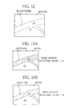
Fig. 12 is an explanatory view of the vessel contrast; -
Fig. 13A is an explanatory view of a standard value of the vessel contrast in the second vessel pattern imaging mode; -
Fig. 13B is an explanatory view of the standard value of the vessel contrast in the third vessel pattern imaging mode; -
Fig. 14 is an explanatory view about fine adjustment of a light intensity ratio; -
Fig. 15 is an explanatory view about gradation conversion processing; -
Fig. 16 is a flowchart of the second vessel pattern imaging mode; and -
Fig. 17 is a graph for explaining how to select illumination light according to another embodiment. - As shown in
Fig. 1 , anendoscope system 10 is constituted of anelectronic endoscope 11, aprocessor device 12, alight source device 13, and amonitor 14. Theelectronic endoscope 11 images the interior of a human body. Theprocessor device 12 produces an endoscopic image from a signal obtained by theelectronic endoscope 11. Thelight source device 13 supplies illumination light to theelectronic endoscope 11 to illuminate an internal body portion to be imaged. The endoscopic image is displayed on themonitor 14. - The
electronic endoscope 11 is provided with aflexible insert section 16 to be introduced into a human body cavity, acontrol handle unit 17 provided at a proximal end of theinsert section 16, and auniversal cord 18 for connecting thecontrol handle unit 17 to theprocessor device 12 and thelight source device 13. Theinsert section 16 is formed with asteering assembly 19 at its distal end. The steeringassembly 19 is made of a plurality of joint pieces and flexibly bent in an arbitrary direction by a turn of anangle knob 21 provided on thecontrol handle unit 17. The steeringassembly 19 is provided with ahead assembly 16a at its distal end. Thehead assembly 16a contains an optical system for imaging the interior of the human body. By bending thesteering assembly 19, thehead assembly 16a is aimed at a desired direction inside the human body. - The control handle
unit 17 is provided with amode switch 15 to change a mode of theendoscope system 10. Theendoscope system 10 has five modes, that is, a normal mode for observing the body portion under irradiation with broad band white light, a first vessel pattern imaging mode for observing the body portion with constant vessel contrast (contrast between a blood vessel and a mucosa) irrespective of variation in an oxygen saturation level of blood, a second vessel pattern imaging mode for displaying a vessel pattern with artificial colors, and a third vessel pattern imaging mode for enhancing the vessel pattern in a bright state, and an oxygen saturation imaging mode for observing an oxygen saturation level of blood. - The
universal cord 18 has amulti connector 24, which includes a communication connector and a light source connector, at its distal end. Theelectronic endoscope 11 is detachably connected to theprocessor device 12 and thelight source device 13 through thismulti connector 24. - As shown in
Fig. 2 , thelight source device 13 includes a first semiconductor light source LD1, a second semiconductor light source LD2, aphosphor 30, a firstoptical fiber 32, a secondoptical fiber 33, and asource controller 35 for controlling operation of the first and second semiconductor light sources LD1 and LD2. The first and second semiconductor light sources LD1 and LD2 are laser light sources made of a laser diode or the like. The first semiconductor light source LD1 emits a first blue laser beam BN1 having a wavelength of 445 nm ± 10 nm. The second semiconductor light source LD2 emits a second blue laser beam BN2 having a wavelength of 405 nm ± 10 nm. The first laser beam BN1 is incident upon thephosphor 30 disposed between the first semiconductor light source LD1 and the firstoptical fiber 32. The second laser beam BN2 enters the secondoptical fiber 33 through acondenser lens 33a. Note that, light emitting diodes (LEDs) may be used as the first and second semiconductor light sources LD1 and LD2. - The
phosphor 30 contains a plurality of types of fluorescent substances (for example, YAG-based fluorescent substance or BAM (BaMgAl10O17)-based fluorescent substance). Thephosphor 30 absorbs most of the first laser beam BN1 emitted from the first semiconductor light source LD1, and emits green to red fluorescence FL having a wavelength of 460 to 700 nm. The remaining first laser beam BN1 passes through thephosphor 30. Therefore, when the first laser beam BN1 is incident upon thephosphor 30, white light (pseudo white light) W is produced by mixing the fluorescence FL and the first laser beam BN1 passed through thephosphor 30. The white light W enters the firstoptical fiber 32 through acondenser lens 32a. - The first and second
optical fibers light guide 43 of theelectronic endoscope 11 via acoupler 36. Thus, the white light W transmitted through the firstoptical fiber 32 and the second laser beam BN2 transmitted through the secondoptical fiber 33 selectively or simultaneously enter thelight guide 43. - The
source controller 35 is connected to amain controller 59 of theprocessor device 12. Thesource controller 35 controls the power on and off of the first and second semiconductor light sources LD1 and LD2 and the light intensity of the first and second laser beams BN1 and BN2 in accordance with the selected mode. In the normal mode, only the first semiconductor light source LD1 is turned on. Thus, the white light W having an emission spectrum shown inFig. 3 is applied to the body portion. - In the first to third vessel pattern imaging modes and the oxygen saturation imaging mode, both the first and second semiconductor light sources LD1 and LD2 are turned on. Thus, as shown in
Figs. 6A ,7A , and8A , the illumination light including the white light W (first laser beam BN1 + fluorescence FL) and the second laser beam BN2 is applied to the body portion. The light intensity ratio between the first and second laser beams BN1 and BN2 is predetermined differently from mode to mode, and is stored in amemory 35a of thesource controller 35. - In the first vessel pattern imaging mode, the first and second laser beams BN1 and BN2 are produced at a predetermined first intensity ratio. At the first intensity ratio, the first and second laser beams BN1 and BN2 are applied at approximately the same light intensity to the body portion. As shown in
Fig. 4 , at thewavelength 445 nm of the first laser beam BN1, a light absorption coefficient of deoxyhemoglobin Hb is larger than that of oxyhemoglobin Hb02. Note that, an isosbestic wavelength (around 420 nm) at which deoxyhemoglobin Hb and oxyhemoglobin HbO2 have the same light absorption coefficient exists between wavelengths of 405 nm and 445 nm. - In the first vessel pattern imaging mode, as shown in
Fig. 5A , the contrast (vessel contrast) between a blood vessel and a mucosa hardly varies in an image, even if the oxygen saturation level decreases from 100%, to 50%, and to 0%. In other words, the vessel pattern is observed in the same vessel contrast no matter if the oxygen saturation level St02 varies. This image obtained in the first vessel pattern imaging mode is referred to as a first vessel pattern image. - The vessel contrast does not vary in the first vessel pattern image, even if an entire light amount (the total light amount of the first laser beam BN1, the second laser beam BN2, and the fluorescence FL) changes due to actuation of AE (auto exposure). For example, as shown in
Fig. 5B , when thehead assembly 16a of theelectronic endoscope 11 gets near the body portion (near view) and a light amount taken in by an imaging section of theelectronic endoscope 11 is increased, the AE is performed so as to reduce the entire light amount. The brightness of the vessel pattern becomes dark owing to the AE, but at the same time, the brightness of the mucosa becomes dark too. Thus, the vessel contrast does not change between before and after the AE. Likewise, the AE has no effect on the vessel contrast in the second and third vessel pattern imaging modes and the oxygen saturation imaging mode. InFigs. 5A and 5B , numbers enclosed by circles represent luminance values. The luminance value is measured on a scale from 1 to 10. A luminance value of "10" indicates the brightest state, and a luminance value of "1" indicates the darkest state. - In the second vessel pattern imaging mode, as shown in
Fig. 6A , the first and second laser beams BN1 and BN2 are produced at a second intensity ratio. At the second intensity ratio, the light intensity L2 of the second laser beam BN2 is higher than the light intensity L1 of the first laser beam BN1. Thus, an image obtained in this mode is susceptible to the second laser beam BN2. As shown inFig. 4 , at thewavelength 405 nm of the second laser beam BN2, the light absorption coefficient of oxyhemoglobin Hb02 is larger than that of deoxyhemoglobin Hb. Accordingly, assuming that the AE does not work, as shown inFig. 6B , the vessel pattern becomes brighter with decrease in the oxygen saturation level from 100%, to 50%, and to 0%. In other words, the vessel contrast varies in accordance with change of the oxygen saturation level. The variation of the vessel contrast is corrected by a light intensity ratio fine-adjustingsection 62 or agradation converting section 63, though details will be described later. The image obtained after the correction of the vessel contrast in the second vessel pattern imaging mode is referred to as a second vessel pattern image. - In the third vessel pattern imaging mode, as shown in
Fig. 7A , the first and second laser beams BN1 and BN2 are produced at a third intensity ratio. At the third intensity ratio, the light intensity L1 of the first laser beam BN1 is higher than the light intensity L2 of the second laser beam BN2. Thus, an image obtained in this mode is susceptible to the first laser beam BN1. As shown inFig. 4 , at thewavelength 445 nm of the first laser beam BN1, the light absorption coefficient of deoxyhemoglobin Hb is larger than that of oxyhemoglobin Hb02. Accordingly, assuming that the AE does not work, as shown inFig. 7B , the vessel pattern becomes darker with decrease in the oxygen saturation level from 100%, to 50%, and to 0%. In other words, the vessel contrast varies in accordance with change of the oxygen saturation level. The variation of the vessel contrast is corrected by the light intensity ratio fine-adjustingsection 62 or thegradation converting section 63, as in the case of the second vessel pattern imaging mode. The image obtained after the correction of the vessel contrast in the third vessel pattern imaging mode is referred to as a third vessel pattern image. - In the oxygen saturation imaging mode, as shown in
Fig. 8A , the first and second laser beams BN1 and BN2 are produced at a StO2 intensity ratio. At the St02 intensity ratio, the light intensity L2 of the second laser beam BN2 is much higher than the light intensity L1 of the first laser beam BN1. Thus, an image obtained in this mode is susceptible to the second laser beam BN2. As shown inFig. 4 , at thewavelength 405 nm of the second laser beam BN2, the light absorption coefficient of oxyhemoglobin Hb02 is larger than that of deoxyhemoglobin Hb. Accordingly, assuming that the AE does not work, as shown inFig. 8B , the vessel pattern becomes brighter with decrease in the oxygen saturation level from 100%, to 50%, and to 0%. Taking advantage of change in the brightness of the vessel pattern, a hypoxic region and a hyperoxic region are visualized in an oxygen saturation image. - As shown in
Fig. 2 , theelectronic endoscope 11 is provided with thelight guide 43, aCCD 44, an analog frontend circuit (AFE) 45, and animaging controller 46. Thelight guide 43 is made of a large diameter optical fiber, a bundle fiber, or the like. Thelight guide 43 is connected to thelight source device 13 at its light incident end, and is aimed at alighting lens 48 at its light exit end. The illumination light transmitted through thelight guide 43 is applied to the body portion through thelighting lens 48 and alighting window 49. - The light reflected from the body portion is incident upon an
imaging surface 44a of theCCD 44 through animaging window 50 and an image-forminglens 51. TheCCD 44 photoelectrically converts the light received by theimaging surface 44a, and accumulates signal charge. The accumulated signal charge is read out as an imaging signal, and is transmitted to theAFE 45. - The
CCD 44 is a color CCD image sensor. Theimaging surface 44a has an arrangement of three-color pixels, i.e. B color pixels having a blue (B) color filter, G color pixels having a green (G) color filter, and R color pixels having a red (R) color filter. The B, G, and R color filters have spectral transmittance represented bycurves Fig. 9 , respectively. Thus, the B color pixel receives light having a wavelength of 380 to 560 nm. The G color pixel receives light having a wavelength of 450 to 630 nm. The R color pixel receives light having a wavelength of 580 to 760 nm. Instead of the CCD image sensor, a CMOS image sensor having RGB color filters may be used. Another CCD image sensor or CMOS image sensor that has not the RGB color filters but CMY color filters, being complimentary color filters, may be used instead. - The
AFE 45 is composed of a correlated double sampling circuit (CDS), an automatic gain controller (AGC), and an analog-to-digital converter (A/D), none of which is illustrated though. The CDS applies correlated double sampling processing to an image signal outputted from theCCD 44, in order to remove noise caused by operation of theCCD 44. The AGC amplifies the image signal after the noise reduction by the CDS. The A/D converts the amplified image signal into a digital image signal of a predetermined bit number, and inputs the digital image signal to theprocessor device 12. - The
imaging controller 46 is connected to themain controller 59 of theprocessor device 12. Theimaging controller 46 issues a drive signal to theCCD 44 under control of themain controller 59. In response to the drive signal, theCCD 44 outputs the image signal to theAFE 45 at a predetermined frame rate. - In the normal mode, as shown in
Fig. 10A , the signal charge is stored and read out within one frame period under irradiation with the white light W (first laser beam BN1 + fluorescence FL). The storage and readout is repeatedly performed as long as theendoscope system 2 is in the normal mode. Thus, a blue signal Bc, a green signal Gc, and a red signal Rc are read out as the image signals from the B, G, and R pixels of theCCD 44, respectively. - In the first to third vessel pattern imaging modes and the oxygen saturation imaging mode, as shown in
Fig. 10B , the storage and readout of the signal charge is performed under irradiation with the white light W (first laser beam BN1 + fluorescence FL) and the second laser beam BN2. Thus, a blue signal Bs, a green signal Gs, and a red signal Rs are read out as the image signals from the B, G, and R pixels of theCCD 44, respectively. - As shown in
Fig. 2 , theprocessor device 12 includes anormal image generator 55, aframe memory 56, aspecial image generator 57, and adisplay controller 58, which are controlled by themain controller 59. Thenormal image generator 55 produces a normal image from the image signals Bc, Gc, and Rc obtained in the normal mode. B, G, and R images of the normal image are assigned to B, G, and R channels of themonitor 14, respectively. The normal image is temporarily stored to theframe memory 56 before being displayed on themonitor 14. - As shown in
Fig. 11 , thespecial image generator 57 is constituted of a vessel patternimage generating section 60 and an oxygen saturationimage generating section 66. The vessel patternimage generating section 60 produces the first to third vessel pattern images from the image signals Bs, Gs, and Rs obtained in the first to third vessel pattern imaging modes. The oxygen saturationimage generating section 66 produces the oxygen saturation image from the image signals Bs, Gs, and Rs obtained in the oxygen saturation imaging mode. The vessel patternimage generating section 60 includes a vesselcontrast judging section 61, a light intensity ratio fine-adjustingsection 62, a colortone adjusting section 65, agradation converting section 63, and animage producing section 64. The vesselcontrast judging section 61 judges whether or not the vessel contrast coincides with a standard value based on the image signals Bs, Gs, and Rs obtained in the second or third vessel pattern imaging mode. When the vessel contrast does not coincide with the standard value, the light intensity ratio fine-adjustingsection 62 finely adjusts the second or third intensity ratio. Then imaging is performed again to obtain the second or third vessel pattern image having the standard vessel contrast. - To be more specific, the vessel
contrast judging section 61 produces a B/G ratio image, which represents the light intensity ratio between the blue signal Bs and the green signal Gs obtained in the second or third vessel pattern imaging mode. In the B/G ratio image, pixels having the B/G ratio that is within a predetermined range constitute a mucosa area, while the other pixels having the B/G ratio that is out of the predetermined range constitute a vessel area. Then, as shown inFig. 12 , the ratio (X:Y) between a light intensity value X of the vessel area and a light intensity value Y of the mucosa area is calculated as the vessel contrast. Whether or not the calculated vessel contrast coincides with the standard value is judged. - The vessel contrast in a state where the oxygen saturation level is 100% is used as the standard value. In the second vessel pattern imaging mode, the vessel pattern becomes the darkest when the oxygen saturation level is 100%. The vessel pattern becomes brighter with decrease in the oxygen saturation level. As shown in
Fig. 13A , when the oxygen saturation level is 100%, if the light intensity value of the vessel area is "2" and the light intensity value of the mucosa area is "8", the standard value of the vessel contrast is "1:4". - In the third vessel pattern imaging mode, on the other hand, the vessel pattern becomes the brightest when the oxygen saturation level is 100%. The vessel pattern becomes darker with decrease in the oxygen saturation level. As shown in
Fig. 13B , when the oxygen saturation level is 100%, if the light intensity value of the vessel area is "6" and the light intensity value of the mucosa area is "8", the standard value of the vessel contrast is "3: 4". Note that, when the body portion to be imaged includes arteries, the vessel contrast in a state where the oxygen saturation level is 100% is preferably used as the standard value. When the body portion includes many veins, the vessel contrast in a state where the oxygen saturation level is 70% is preferably used as the standard value. - When the vessel contrast does not coincide with the standard value, the light intensity ratio fine-adjusting
section 62 corrects the vessel contrast by fine adjustment of the second or third intensity ratio. In the second vessel pattern imaging mode, as shown inFig. 14 , the light intensity of the second laser beam BN2 having a wavelength of 405 nm is higher than that of the first laser beam BN1 having a wavelength of 445 nm. When the vessel pattern becomes bright due to decrease in the oxygen saturation level, the vessel contrast does not coincide with the standard value. - Therefore, the light intensity ratio fine-adjusting
section 62 drives thesource controller 35 of thelight source device 13 so as to decrease the light intensity of the second laser beam BN2 and increase the light intensity of the first laser beam BN1. Thus, the second intensity ratio is finely adjusted, so the vessel pattern becomes dark just as in the case of the oxygen saturation level of 100%. In a case where a color tone of the mucosa is changed owing to the fine adjustment of the second intensity ratio, the colortone adjusting section 65 adjusts the color tone of the mucosa area. In the third vessel pattern imaging mode, the fine adjustment of the third intensity ratio is performed in a like manner. - When the vessel contrast does not coincide with the standard value, the
gradation converting section 63 may correct the vessel contrast by converting a gradation of the blood vessel, instead of or in addition to the correction of the vessel contrast by the light intensity ratio fine-adjustingsection 62. In the second vessel pattern imaging mode, as described above, when the vessel pattern becomes bright due to decrease in the oxygen saturation level, the vessel contrast does not coincide with the standard value. In this case, as shown inFig. 15 , thegradation converting section 63 produces a vessel area image, which shows only the vessel area, and a mucosa area image, which shows an area excluding the vessel area and including the mucosa area and the like, from the image signals Bs, Gs, and Rs obtained in the second vessel pattern imaging mode. The vessel area image is produced by extracting the vessel area in which the signal ratio (B/G ratio) between the blue signal Bs and the green signal Gs is out of the predetermined range. The mucosa area image is produced by extracting the mucosa area in which the B/G ratio is within the predetermined range. - Then, the
gradation converting section 63 applies gradation conversion processing to the vessel area image so as to convert a luminance value of "4" of the vessel area into a luminance value of "2", which is a luminance value of the vessel area in a state where the oxygen saturation level is 100%. The vessel area image after being subjected to the gradation conversion processing is merged with the mucosa area image, to obtain an image that has the vessel contrast coinciding with the standard value. In the third vessel pattern imaging mode, the gradation conversion processing is carried out in a like manner. - In the first vessel pattern imaging mode, the
image producing section 64 produces the first vessel pattern image from the image signals Bs, Gs, and Rs obtained by theelectronic endoscope 11. B, G, and R images of the first vessel pattern image are assigned to the B, G, and R channels of themonitor 14, respectively. In the first vessel pattern image, as shown inFig. 5A , the vessel contrast is invariant irrespective of change of the oxygen saturation level, so the vessel pattern is seen in the same manner. The first vessel pattern image is temporarily stored to theframe memory 56 before being displayed on themonitor 14. The same goes for the second and third vessel pattern images as described below. - In the second vessel pattern imaging mode, the
image producing section 64 produces the second vessel pattern image from the image signals Bs, Gs, and Rs obtained under irradiation with the illumination light having the fine-adjusted second intensity ratio or the blue signal Bs and the green signal Gs after being subjected to the gradation conversion processing. A B image of the second vessel pattern image is assigned to the B and G channels of themonitor 14, while a G image of the second vessel pattern image is assigned to the R channel of themonitor 14. Thus, the entire body portion including the vessel pattern is colored artificially in the second vessel pattern image. - In the third vessel pattern imaging mode, the
image producing section 64 produces the third vessel pattern image from the image signals Bs, Gs, and Rs obtained under irradiation with the illumination light having the fine-adjusted third intensity ratio or the image signals Bs, Gs, and Rs after being subjected to the gradation conversion processing. B, G, and R images of the third vessel pattern image are assigned to the B, G, and R channels of themonitor 14, respectively. Thus, in the third vessel pattern image, the vessel pattern is emphasized on living body tissue that is displayed with color having brightness of a certain value or more. - The oxygen saturation
image generating section 66 has a correlation memory (not shown) that stores in advance the correlation between the oxygen saturation level and the image signals Bs, Gs, and Rs. The oxygen saturation level is obtained from this correlation by looking up an oxygen saturation value based on the image signals Bs, Gs, and Rs obtained in the oxygen saturation imaging mode. Based on the obtained oxygen saturation level, the oxygen saturation image is produced. Note that, in the oxygen saturation image, the entire image may be assigned with artificial colors in accordance with the oxygen saturation level. Alternatively, only the hypoxic region having a low oxygen saturation value may be colored artificially, while the remains of the image may be colored just as with the normal image. - Next, the operation of the second vessel pattern imaging mode will be described with referring to a flowchart of
Fig. 16 . The operation of the third vessel pattern imaging mode is the same as that of the second vessel pattern imaging mode, so the description thereof will be omitted. In the second vessel pattern imaging mode, the first and second laser beams BN1 and BN2 and the fluorescence FL are applied to the body portion at the second intensity ratio at which the intensity of the second laser beam BN2 is higher than that of the first laser beam BN1. Thecolor CCD 44 takes an image of the body portion under irradiation with the first and second laser beams BN1 and BN2 and the fluorescence FL, to obtain the image signals Bs, Gs, and Rs. - The vessel contrast being the contrast between the blood vessel and the mucosa is calculated from the image signals Bs, Gs, and Rs. When the vessel contrast coincides with the predetermined standard value, the second vessel pattern image is produced from the image signals Bs, Gs, and Rs. When the vessel contrast dose not coincide with the standard value, on the other hand, the second intensity ratio is finely adjusted so that the vessel contrast is made coincide with the standard value. In the fine adjustment of the second intensity ratio, the light intensity of the second laser beam BN2 is decreased and the light intensity of the first laser beam BN1 is increased, while keeping the entire light intensity (the total light intensity of the first laser beam BN1, the second laser beam BN2, and the fluorescence FL) constant. In a case where the fine adjustment of the second intensity ratio brings about change in a color tone of the mucosa area, color tone adjustment is performed so as to convert the color tone of the mucosa area back into a state before the fine adjustment. After that, the second vessel pattern image is produced from the image signals Bs, Gs, and Rs obtained after the fine adjustment of the second intensity ratio. The produced second vessel pattern image is displayed on the
monitor 14. - In the above embodiments, in the first vessel pattern imaging mode, the light intensity ratio between the first and second blue laser beams BN1 and BN2, which have different wavelengths between which the isosbestic wavelength exists, is set at a predetermined value, for the purpose of keeping the vessel contrast constant no matter if the oxygen saturation level St02 is changed. However, to keep the vessel contrast constant, narrow band light may be used that has two wavelengths between which the isosbestic wavelength exists and between which an absolute value of the difference in the light absorption coefficient between oxyhemoglobin and deoxyhemoglobin is the same. Alternatively, narrow band light having another single wavelength may be used, in addition to narrow band light having two wavelengths between the which isosbestic wavelength exists.
- For example, as shown in
Fig. 17 , when two types of narrow band light having wavelengths S1 and S2 are applied simultaneously to the body portion, an absolute value D1 of the difference in the light absorption coefficient between oxyhemoglobin and deoxyhemoglobin at the wavelength S1 is larger than an absolute value D2 of the difference in the light absorption coefficient between oxyhemoglobin and deoxyhemoglobin at the wavelength S2. Accordingly, in order to keep the vessel contrast constant irrespective of change of the oxygen saturation level StO2, the light intensity ratio between the two types of narrow band light must be set appropriately. Instead of this, another type of narrow band light having a wavelength S3 is applied in addition to the two types of narrow band light. At the wavelength S3, just as with the wavelength S2, the light absorption coefficient of oxyhemoglobin is higher than that of deoxyhemoglobin. "D3" represents an absolute value of the difference in the light absorption coefficient between oxyhemoglobin and deoxyhemoglobin. If "D1=D2+D3" holds true, the vessel contrast can be kept constant even if every type of narrow band light is applied at the same light intensity. - In the above embodiments, the first and second laser beams BN1 and BN2 are applied simultaneously. However, the first and second laser beams BN1 and BN2 may be applied sequentially, and images may be captured sequentially in synchronization with the application of the first and second laser beams BN1 and BN2. The image captured under irradiation with the first laser beam BN1 may be merged with the image captured under irradiation with the second laser beam BN2, and the merged image may be subjected to image processing to make the vessel contrast constant.
- In the above embodiments, after the fine adjustment of the second intensity ratio, the color tone of the mucosa is adjusted to make the vessel contrast constant. Instead of this, the gradation conversion processing may be applied to the mucosa area in the image after the fine adjustment of the second intensity ratio.
- The above embodiments describe the endoscope system in which the vessel contrast is adjusted in the image obtained by the electronic endoscope. However, the present invention is applicable to another type of endoscope system such as a fiber scope by which the internal body portion is seen directly under irradiation with the illumination light. In this case, the endoscope system emits a plurality of types of illumination light the light intensity of which is independently adjustable. The light intensity ratio among the plurality of types of illumination light is finely adjusted, in order to produce vision of object tissue having the invariant vessel contrast.
- Although the present invention has been fully described by the way of the preferred embodiment thereof with reference to the accompanying drawings, various changes and modifications will be apparent to those having skill in this field. Therefore, unless otherwise these changes and modifications depart from the scope of the present invention, they should be construed as included therein.
Claims (15)
- An endoscope system (10) comprising:a first semiconductor light source for emitting first illumination light having a first wavelength;a second semiconductor light source for emitting second illumination light having a second wavelength, an isosbestic wavelength of oxyhemoglobin and deoxyhemoglobin existing between said first and second wavelengths;an imaging device (11) for imaging an internal body portion irradiated with said first or second illumination light;a vessel pattern image generating section (60) for producing a vessel pattern image based on an image signal obtained by said imaging device (11);a contrast adjusting section (62, 63, 65) for adjusting vessel contrast being contrast between a vessel area and an area other than said vessel area in said vessel pattern image.
- The endoscope system (10) according to claim 1, wherein said contrast adjusting section includes a light intensity ratio fine-adjusting section (62) for finely adjusting a light intensity ratio between said first and second illumination light.
- The endoscope system (10) according to claim 2, wherein said contrast adjusting section further includes a color tone adjusting section (65) for adjusting a color tone of said vessel pattern image.
- The endoscope system (10) according to claim 1, wherein said contrast adjusting section includes a gradation converting section (63) for applying gradation conversion processing to said vessel pattern image.
- The endoscope system (10) according to claim 2 or 3, wherein said contrast adjusting section further includes a gradation converting section (63) for applying gradation conversion processing to said vessel pattern image.
- The endoscope system (10) according to claim 5, wherein said light intensity ratio fine-adjusting section (62) finely adjusts said light intensity ratio between said first and second illumination light; and
said gradation converting section (63) applies said gradation conversion processing to said vessel pattern image captured under irradiation with said first and second illumination light having finely adjusted intensity. - The endoscope system (10) according to one of claims 1 to 5, wherein said contrast adjusting section (62, 63, 65) adjusts change of said vessel contrast caused by change of an oxygen saturation level of blood in said vessel pattern image.
- The endoscope system (10) according to one of claims 1 to 7, wherein said first and second illumination light is applied simultaneously to said internal body portion.
- The endoscope system (10) according to one of claims 1 to 7, wherein said first and second illumination light is applied sequentially to said internal body portion.
- The endoscope system (10) according to one of claims 1 to 9 being switchable between a vessel pattern imaging mode in which said vessel pattern image is displayed on a monitor and an oxygen saturation imaging mode in which an oxygen saturation image is displayed on said monitor, an oxygen saturation level of blood being imaged in said oxygen saturation image based on said image signal.
- The endoscope system (10) according to claim 10, wherein in said oxygen saturation imaging mode, said light intensity of said first or second illumination light is increased in order to increase difference in brightness between a hyperoxic region having said high oxygen saturation level and a hypoxic region having said low oxygen saturation level.
- The endoscope system (10) according to one of claims 1 to 11, wherein
D1≅D2 holds true, wherein
D1 represents an absolute value of difference in a light absorption coefficient between said oxyhemoglobin and said deoxyhemoglobin at said first wavelength; and
D2 represents an absolute value of difference in said light absorption coefficient between said oxyhemoglobin and said deoxyhemoglobin at said second wavelength. - The endoscope system (10) according to one of claims 1 to 11, further comprising:a third semiconductor light source for emitting third illumination light having a third wavelength to said internal body portion, said third wavelength being different from said first and second wavelengths; whereinD1≅D2+D3 holds true, whereinD1 represents an absolute value of difference in a light absorption coefficient between said oxyhemoglobin and said deoxyhemoglobin at said first wavelength;D2 represents an absolute value of difference in said light absorption coefficient between said oxyhemoglobin and said deoxyhemoglobin at said second wavelength; andD3 represents an absolute value of difference in said light absorption coefficient between said oxyhemoglobin and said deoxyhemoglobin at said third wavelength.
- A processor device (12) of an endoscope system (10) including an electronic endoscope (11) for imaging an internal body portion under irradiation with first illumination light having a first wavelength and second illumination light having a second wavelength, an isosbestic wavelength of oxyhemoglobin and deoxyhemoglobin existing between said first and second wavelengths, said processor device (12) comprising:a vessel pattern image generating section (60) for producing a vessel pattern image based on an image signal obtained by said electronic endoscope (11); anda contrast adjusting section (62, 63, 65) for adjusting vessel contrast being contrast between a vessel area and an area other than said vessel area in said vessel pattern image.
- An image producing method comprising the steps of:emitting first illumination light having a first wavelength from a first semiconductor light source, and emitting second illumination light having a second wavelength from a second semiconductor light source, an isosbestic wavelength of oxyhemoglobin and deoxyhemoglobin existing between said first and second wavelengths;imaging an internal body portion irradiated with said first or second illumination light with an imaging device (11);producing a vessel pattern image based on an image signal obtained by said imaging device (11); andadjusting by a contrast adjusting section (62, 63, 65) vessel contrast being contrast between a vessel area and an area other than said vessel area in said vessel pattern image.
Applications Claiming Priority (1)
| Application Number | Priority Date | Filing Date | Title |
|---|---|---|---|
| JP2012117725A JP5698186B2 (en) | 2012-05-23 | 2012-05-23 | Endoscope system, processor device for endoscope system, and method for operating endoscope system |
Publications (2)
| Publication Number | Publication Date |
|---|---|
| EP2666403A1 true EP2666403A1 (en) | 2013-11-27 |
| EP2666403B1 EP2666403B1 (en) | 2017-06-21 |
Family
ID=48288849
Family Applications (1)
| Application Number | Title | Priority Date | Filing Date |
|---|---|---|---|
| EP13166229.8A Active EP2666403B1 (en) | 2012-05-23 | 2013-05-02 | Endoscope system and processor device thereof |
Country Status (2)
| Country | Link |
|---|---|
| EP (1) | EP2666403B1 (en) |
| JP (1) | JP5698186B2 (en) |
Cited By (3)
| Publication number | Priority date | Publication date | Assignee | Title |
|---|---|---|---|---|
| WO2016177622A1 (en) * | 2015-05-07 | 2016-11-10 | Koninklijke Philips N.V. | High intensity light source with temperature independent color point |
| US10085629B2 (en) | 2015-03-25 | 2018-10-02 | Olympus Corporation | Observation system |
| CN110087528A (en) * | 2017-01-16 | 2019-08-02 | Hoya株式会社 | Endoscopic system and image display device |
Families Citing this family (3)
| Publication number | Priority date | Publication date | Assignee | Title |
|---|---|---|---|---|
| JP6412709B2 (en) | 2014-04-02 | 2018-10-24 | オリンパス株式会社 | Observation image acquisition system |
| JP6386939B2 (en) * | 2015-02-27 | 2018-09-05 | 富士フイルム株式会社 | Endoscope light source device, endoscope system, and operation method of endoscope light source device |
| JP6690003B2 (en) * | 2016-10-03 | 2020-04-28 | 富士フイルム株式会社 | Endoscope system and operating method thereof |
Citations (5)
| Publication number | Priority date | Publication date | Assignee | Title |
|---|---|---|---|---|
| US5515449A (en) * | 1989-01-26 | 1996-05-07 | Olympus Optical Co., Ltd. | Endoscope image processing apparatus |
| EP2106736A2 (en) * | 2008-04-02 | 2009-10-07 | Fujifilm Corporation | Image capturing apparatus, image capturing method, and computer-readable medium |
| US20100266202A1 (en) * | 2008-10-27 | 2010-10-21 | Olympus Medical Systems Corp. | Imaging processor, body-introducable apparatus, medical system and image processing method |
| EP2452610A1 (en) | 2009-07-06 | 2012-05-16 | FUJIFILM Corporation | Lighting device for endoscope, and endoscope device |
| WO2013049264A1 (en) * | 2011-09-28 | 2013-04-04 | Carestream Health, Inc. | Frame-sequential multiwavelength imaging system and method |
Family Cites Families (4)
| Publication number | Priority date | Publication date | Assignee | Title |
|---|---|---|---|---|
| JP2011065291A (en) * | 2009-09-15 | 2011-03-31 | Hoya Corp | Enhanced-image processor and medical observation system |
| JP5389742B2 (en) * | 2009-09-30 | 2014-01-15 | 富士フイルム株式会社 | Electronic endoscope system, processor device for electronic endoscope, and method for operating electronic endoscope system |
| JP2012016545A (en) * | 2010-07-09 | 2012-01-26 | Fujifilm Corp | Endoscope apparatus |
| JP5496852B2 (en) * | 2010-10-26 | 2014-05-21 | 富士フイルム株式会社 | Electronic endoscope system, processor device for electronic endoscope system, and method for operating electronic endoscope system |
-
2012
- 2012-05-23 JP JP2012117725A patent/JP5698186B2/en active Active
-
2013
- 2013-05-02 EP EP13166229.8A patent/EP2666403B1/en active Active
Patent Citations (5)
| Publication number | Priority date | Publication date | Assignee | Title |
|---|---|---|---|---|
| US5515449A (en) * | 1989-01-26 | 1996-05-07 | Olympus Optical Co., Ltd. | Endoscope image processing apparatus |
| EP2106736A2 (en) * | 2008-04-02 | 2009-10-07 | Fujifilm Corporation | Image capturing apparatus, image capturing method, and computer-readable medium |
| US20100266202A1 (en) * | 2008-10-27 | 2010-10-21 | Olympus Medical Systems Corp. | Imaging processor, body-introducable apparatus, medical system and image processing method |
| EP2452610A1 (en) | 2009-07-06 | 2012-05-16 | FUJIFILM Corporation | Lighting device for endoscope, and endoscope device |
| WO2013049264A1 (en) * | 2011-09-28 | 2013-04-04 | Carestream Health, Inc. | Frame-sequential multiwavelength imaging system and method |
Cited By (8)
| Publication number | Priority date | Publication date | Assignee | Title |
|---|---|---|---|---|
| US10085629B2 (en) | 2015-03-25 | 2018-10-02 | Olympus Corporation | Observation system |
| WO2016177622A1 (en) * | 2015-05-07 | 2016-11-10 | Koninklijke Philips N.V. | High intensity light source with temperature independent color point |
| KR20180013954A (en) * | 2015-05-07 | 2018-02-07 | 루미리즈 홀딩 비.브이. | High intensity light source with temperature independent color |
| CN108541296A (en) * | 2015-05-07 | 2018-09-14 | 亮锐控股有限公司 | High-intensity light source with temperature independence color dot |
| US10495286B2 (en) | 2015-05-07 | 2019-12-03 | Lumileds Llc | High intensity light source with temperature independent color point |
| TWI688728B (en) * | 2015-05-07 | 2020-03-21 | 荷蘭商露明控股公司 | Lighting device and lighting apparatus |
| KR102527057B1 (en) | 2015-05-07 | 2023-05-02 | 루미리즈 홀딩 비.브이. | High intensity light source with temperature independent color point |
| CN110087528A (en) * | 2017-01-16 | 2019-08-02 | Hoya株式会社 | Endoscopic system and image display device |
Also Published As
| Publication number | Publication date |
|---|---|
| JP5698186B2 (en) | 2015-04-08 |
| JP2013244041A (en) | 2013-12-09 |
| EP2666403B1 (en) | 2017-06-21 |
Similar Documents
| Publication | Publication Date | Title |
|---|---|---|
| US9943230B2 (en) | Endoscope system, processor device of endoscope system, and image processing method | |
| JP5303012B2 (en) | Endoscope system, processor device for endoscope system, and method for operating endoscope system | |
| JP5554253B2 (en) | Electronic endoscope system | |
| US9526408B2 (en) | Electronic endoscope system and method for controlling the same | |
| JP5550574B2 (en) | Electronic endoscope system | |
| US9629527B2 (en) | Endoscope system, processor device of endoscope system, and image processing method | |
| US20120253122A1 (en) | Endoscope system and calibration method | |
| EP2666403B1 (en) | Endoscope system and processor device thereof | |
| JP5762344B2 (en) | Image processing apparatus and endoscope system | |
| US10034600B2 (en) | Endoscope apparatus with spectral intensity control | |
| US9414739B2 (en) | Imaging apparatus for controlling fluorescence imaging in divided imaging surface | |
| JPWO2015016013A1 (en) | Endoscope light source device and endoscope system using the same | |
| JP6100674B2 (en) | Endoscope light source device and endoscope system | |
| JP5789345B2 (en) | Endoscope system | |
| JP5997630B2 (en) | Light source device and endoscope system using the same | |
| US20130053703A1 (en) | Endoscopic diagnosis system | |
| JP5780653B2 (en) | Light source device and endoscope system | |
| JP2016174976A (en) | Endoscope system | |
| JP6325707B2 (en) | Endoscope light source device and endoscope system | |
| JP7163487B2 (en) | Endoscope light source device and endoscope system | |
| JP5695684B2 (en) | Electronic endoscope system | |
| JP6454755B2 (en) | Endoscope system | |
| JP5965028B2 (en) | Endoscope system | |
| JP6970777B2 (en) | Endoscope system | |
| JP7235832B2 (en) | endoscope system |
Legal Events
| Date | Code | Title | Description |
|---|---|---|---|
| PUAI | Public reference made under article 153(3) epc to a published international application that has entered the european phase |
Free format text: ORIGINAL CODE: 0009012 |
|
| AK | Designated contracting states |
Kind code of ref document: A1 Designated state(s): AL AT BE BG CH CY CZ DE DK EE ES FI FR GB GR HR HU IE IS IT LI LT LU LV MC MK MT NL NO PL PT RO RS SE SI SK SM TR |
|
| AX | Request for extension of the european patent |
Extension state: BA ME |
|
| 17P | Request for examination filed |
Effective date: 20140514 |
|
| RBV | Designated contracting states (corrected) |
Designated state(s): AL AT BE BG CH CY CZ DE DK EE ES FI FR GB GR HR HU IE IS IT LI LT LU LV MC MK MT NL NO PL PT RO RS SE SI SK SM TR |
|
| 17Q | First examination report despatched |
Effective date: 20150819 |
|
| GRAP | Despatch of communication of intention to grant a patent |
Free format text: ORIGINAL CODE: EPIDOSNIGR1 |
|
| INTG | Intention to grant announced |
Effective date: 20160510 |
|
| RIN1 | Information on inventor provided before grant (corrected) |
Inventor name: YAMAGUCHI, HIROSHI |
|
| GRAJ | Information related to disapproval of communication of intention to grant by the applicant or resumption of examination proceedings by the epo deleted |
Free format text: ORIGINAL CODE: EPIDOSDIGR1 |
|
| INTC | Intention to grant announced (deleted) | ||
| GRAS | Grant fee paid |
Free format text: ORIGINAL CODE: EPIDOSNIGR3 |
|
| GRAP | Despatch of communication of intention to grant a patent |
Free format text: ORIGINAL CODE: EPIDOSNIGR1 |
|
| INTG | Intention to grant announced |
Effective date: 20170222 |
|
| GRAA | (expected) grant |
Free format text: ORIGINAL CODE: 0009210 |
|
| AK | Designated contracting states |
Kind code of ref document: B1 Designated state(s): AL AT BE BG CH CY CZ DE DK EE ES FI FR GB GR HR HU IE IS IT LI LT LU LV MC MK MT NL NO PL PT RO RS SE SI SK SM TR |
|
| REG | Reference to a national code |
Ref country code: GB Ref legal event code: FG4D |
|
| REG | Reference to a national code |
Ref country code: CH Ref legal event code: EP |
|
| REG | Reference to a national code |
Ref country code: IE Ref legal event code: FG4D |
|
| REG | Reference to a national code |
Ref country code: AT Ref legal event code: REF Ref document number: 902194 Country of ref document: AT Kind code of ref document: T Effective date: 20170715 |
|
| REG | Reference to a national code |
Ref country code: DE Ref legal event code: R096 Ref document number: 602013022468 Country of ref document: DE |
|
| REG | Reference to a national code |
Ref country code: NL Ref legal event code: MP Effective date: 20170621 |
|
| PG25 | Lapsed in a contracting state [announced via postgrant information from national office to epo] |
Ref country code: NO Free format text: LAPSE BECAUSE OF FAILURE TO SUBMIT A TRANSLATION OF THE DESCRIPTION OR TO PAY THE FEE WITHIN THE PRESCRIBED TIME-LIMIT Effective date: 20170921 Ref country code: HR Free format text: LAPSE BECAUSE OF FAILURE TO SUBMIT A TRANSLATION OF THE DESCRIPTION OR TO PAY THE FEE WITHIN THE PRESCRIBED TIME-LIMIT Effective date: 20170621 Ref country code: LT Free format text: LAPSE BECAUSE OF FAILURE TO SUBMIT A TRANSLATION OF THE DESCRIPTION OR TO PAY THE FEE WITHIN THE PRESCRIBED TIME-LIMIT Effective date: 20170621 Ref country code: GR Free format text: LAPSE BECAUSE OF FAILURE TO SUBMIT A TRANSLATION OF THE DESCRIPTION OR TO PAY THE FEE WITHIN THE PRESCRIBED TIME-LIMIT Effective date: 20170922 Ref country code: FI Free format text: LAPSE BECAUSE OF FAILURE TO SUBMIT A TRANSLATION OF THE DESCRIPTION OR TO PAY THE FEE WITHIN THE PRESCRIBED TIME-LIMIT Effective date: 20170621 |
|
| REG | Reference to a national code |
Ref country code: LT Ref legal event code: MG4D |
|
| REG | Reference to a national code |
Ref country code: AT Ref legal event code: MK05 Ref document number: 902194 Country of ref document: AT Kind code of ref document: T Effective date: 20170621 |
|
| PG25 | Lapsed in a contracting state [announced via postgrant information from national office to epo] |
Ref country code: NL Free format text: LAPSE BECAUSE OF FAILURE TO SUBMIT A TRANSLATION OF THE DESCRIPTION OR TO PAY THE FEE WITHIN THE PRESCRIBED TIME-LIMIT Effective date: 20170621 Ref country code: SE Free format text: LAPSE BECAUSE OF FAILURE TO SUBMIT A TRANSLATION OF THE DESCRIPTION OR TO PAY THE FEE WITHIN THE PRESCRIBED TIME-LIMIT Effective date: 20170621 Ref country code: LV Free format text: LAPSE BECAUSE OF FAILURE TO SUBMIT A TRANSLATION OF THE DESCRIPTION OR TO PAY THE FEE WITHIN THE PRESCRIBED TIME-LIMIT Effective date: 20170621 Ref country code: BG Free format text: LAPSE BECAUSE OF FAILURE TO SUBMIT A TRANSLATION OF THE DESCRIPTION OR TO PAY THE FEE WITHIN THE PRESCRIBED TIME-LIMIT Effective date: 20170921 Ref country code: RS Free format text: LAPSE BECAUSE OF FAILURE TO SUBMIT A TRANSLATION OF THE DESCRIPTION OR TO PAY THE FEE WITHIN THE PRESCRIBED TIME-LIMIT Effective date: 20170621 |
|
| PG25 | Lapsed in a contracting state [announced via postgrant information from national office to epo] |
Ref country code: EE Free format text: LAPSE BECAUSE OF FAILURE TO SUBMIT A TRANSLATION OF THE DESCRIPTION OR TO PAY THE FEE WITHIN THE PRESCRIBED TIME-LIMIT Effective date: 20170621 Ref country code: SK Free format text: LAPSE BECAUSE OF FAILURE TO SUBMIT A TRANSLATION OF THE DESCRIPTION OR TO PAY THE FEE WITHIN THE PRESCRIBED TIME-LIMIT Effective date: 20170621 Ref country code: CZ Free format text: LAPSE BECAUSE OF FAILURE TO SUBMIT A TRANSLATION OF THE DESCRIPTION OR TO PAY THE FEE WITHIN THE PRESCRIBED TIME-LIMIT Effective date: 20170621 Ref country code: RO Free format text: LAPSE BECAUSE OF FAILURE TO SUBMIT A TRANSLATION OF THE DESCRIPTION OR TO PAY THE FEE WITHIN THE PRESCRIBED TIME-LIMIT Effective date: 20170621 Ref country code: AT Free format text: LAPSE BECAUSE OF FAILURE TO SUBMIT A TRANSLATION OF THE DESCRIPTION OR TO PAY THE FEE WITHIN THE PRESCRIBED TIME-LIMIT Effective date: 20170621 |
|
| PG25 | Lapsed in a contracting state [announced via postgrant information from national office to epo] |
Ref country code: PL Free format text: LAPSE BECAUSE OF FAILURE TO SUBMIT A TRANSLATION OF THE DESCRIPTION OR TO PAY THE FEE WITHIN THE PRESCRIBED TIME-LIMIT Effective date: 20170621 Ref country code: IS Free format text: LAPSE BECAUSE OF FAILURE TO SUBMIT A TRANSLATION OF THE DESCRIPTION OR TO PAY THE FEE WITHIN THE PRESCRIBED TIME-LIMIT Effective date: 20171021 Ref country code: IT Free format text: LAPSE BECAUSE OF FAILURE TO SUBMIT A TRANSLATION OF THE DESCRIPTION OR TO PAY THE FEE WITHIN THE PRESCRIBED TIME-LIMIT Effective date: 20170621 Ref country code: SM Free format text: LAPSE BECAUSE OF FAILURE TO SUBMIT A TRANSLATION OF THE DESCRIPTION OR TO PAY THE FEE WITHIN THE PRESCRIBED TIME-LIMIT Effective date: 20170621 Ref country code: ES Free format text: LAPSE BECAUSE OF FAILURE TO SUBMIT A TRANSLATION OF THE DESCRIPTION OR TO PAY THE FEE WITHIN THE PRESCRIBED TIME-LIMIT Effective date: 20170621 |
|
| REG | Reference to a national code |
Ref country code: DE Ref legal event code: R097 Ref document number: 602013022468 Country of ref document: DE |
|
| REG | Reference to a national code |
Ref country code: FR Ref legal event code: PLFP Year of fee payment: 6 |
|
| PLBE | No opposition filed within time limit |
Free format text: ORIGINAL CODE: 0009261 |
|
| STAA | Information on the status of an ep patent application or granted ep patent |
Free format text: STATUS: NO OPPOSITION FILED WITHIN TIME LIMIT |
|
| PG25 | Lapsed in a contracting state [announced via postgrant information from national office to epo] |
Ref country code: DK Free format text: LAPSE BECAUSE OF FAILURE TO SUBMIT A TRANSLATION OF THE DESCRIPTION OR TO PAY THE FEE WITHIN THE PRESCRIBED TIME-LIMIT Effective date: 20170621 |
|
| 26N | No opposition filed |
Effective date: 20180322 |
|
| PG25 | Lapsed in a contracting state [announced via postgrant information from national office to epo] |
Ref country code: SI Free format text: LAPSE BECAUSE OF FAILURE TO SUBMIT A TRANSLATION OF THE DESCRIPTION OR TO PAY THE FEE WITHIN THE PRESCRIBED TIME-LIMIT Effective date: 20170621 |
|
| REG | Reference to a national code |
Ref country code: CH Ref legal event code: PL |
|
| REG | Reference to a national code |
Ref country code: BE Ref legal event code: MM Effective date: 20180531 |
|
| PG25 | Lapsed in a contracting state [announced via postgrant information from national office to epo] |
Ref country code: MC Free format text: LAPSE BECAUSE OF FAILURE TO SUBMIT A TRANSLATION OF THE DESCRIPTION OR TO PAY THE FEE WITHIN THE PRESCRIBED TIME-LIMIT Effective date: 20170621 |
|
| REG | Reference to a national code |
Ref country code: IE Ref legal event code: MM4A |
|
| PG25 | Lapsed in a contracting state [announced via postgrant information from national office to epo] |
Ref country code: LI Free format text: LAPSE BECAUSE OF NON-PAYMENT OF DUE FEES Effective date: 20180531 Ref country code: CH Free format text: LAPSE BECAUSE OF NON-PAYMENT OF DUE FEES Effective date: 20180531 |
|
| PG25 | Lapsed in a contracting state [announced via postgrant information from national office to epo] |
Ref country code: LU Free format text: LAPSE BECAUSE OF NON-PAYMENT OF DUE FEES Effective date: 20180502 |
|
| PG25 | Lapsed in a contracting state [announced via postgrant information from national office to epo] |
Ref country code: IE Free format text: LAPSE BECAUSE OF NON-PAYMENT OF DUE FEES Effective date: 20180502 |
|
| PG25 | Lapsed in a contracting state [announced via postgrant information from national office to epo] |
Ref country code: BE Free format text: LAPSE BECAUSE OF NON-PAYMENT OF DUE FEES Effective date: 20180531 |
|
| PG25 | Lapsed in a contracting state [announced via postgrant information from national office to epo] |
Ref country code: MT Free format text: LAPSE BECAUSE OF NON-PAYMENT OF DUE FEES Effective date: 20180502 |
|
| PG25 | Lapsed in a contracting state [announced via postgrant information from national office to epo] |
Ref country code: TR Free format text: LAPSE BECAUSE OF FAILURE TO SUBMIT A TRANSLATION OF THE DESCRIPTION OR TO PAY THE FEE WITHIN THE PRESCRIBED TIME-LIMIT Effective date: 20170621 |
|
| PG25 | Lapsed in a contracting state [announced via postgrant information from national office to epo] |
Ref country code: PT Free format text: LAPSE BECAUSE OF FAILURE TO SUBMIT A TRANSLATION OF THE DESCRIPTION OR TO PAY THE FEE WITHIN THE PRESCRIBED TIME-LIMIT Effective date: 20170621 Ref country code: HU Free format text: LAPSE BECAUSE OF FAILURE TO SUBMIT A TRANSLATION OF THE DESCRIPTION OR TO PAY THE FEE WITHIN THE PRESCRIBED TIME-LIMIT; INVALID AB INITIO Effective date: 20130502 |
|
| PG25 | Lapsed in a contracting state [announced via postgrant information from national office to epo] |
Ref country code: CY Free format text: LAPSE BECAUSE OF FAILURE TO SUBMIT A TRANSLATION OF THE DESCRIPTION OR TO PAY THE FEE WITHIN THE PRESCRIBED TIME-LIMIT Effective date: 20170621 Ref country code: MK Free format text: LAPSE BECAUSE OF NON-PAYMENT OF DUE FEES Effective date: 20170621 |
|
| PG25 | Lapsed in a contracting state [announced via postgrant information from national office to epo] |
Ref country code: AL Free format text: LAPSE BECAUSE OF FAILURE TO SUBMIT A TRANSLATION OF THE DESCRIPTION OR TO PAY THE FEE WITHIN THE PRESCRIBED TIME-LIMIT Effective date: 20170621 |
|
| REG | Reference to a national code |
Ref country code: FR Ref legal event code: PLFP Year of fee payment: 11 |
|
| PGFP | Annual fee paid to national office [announced via postgrant information from national office to epo] |
Ref country code: GB Payment date: 20230330 Year of fee payment: 11 |
|
| P01 | Opt-out of the competence of the unified patent court (upc) registered |
Effective date: 20230515 |
|
| PGFP | Annual fee paid to national office [announced via postgrant information from national office to epo] |
Ref country code: FR Payment date: 20230411 Year of fee payment: 11 Ref country code: DE Payment date: 20230331 Year of fee payment: 11 |