EP2666416A2 - Removable medical retractor tip - Google Patents
Removable medical retractor tip Download PDFInfo
- Publication number
- EP2666416A2 EP2666416A2 EP13168805.3A EP13168805A EP2666416A2 EP 2666416 A2 EP2666416 A2 EP 2666416A2 EP 13168805 A EP13168805 A EP 13168805A EP 2666416 A2 EP2666416 A2 EP 2666416A2
- Authority
- EP
- European Patent Office
- Prior art keywords
- removable tip
- retractor
- distal
- medical retractor
- shaped body
- Prior art date
- Legal status (The legal status is an assumption and is not a legal conclusion. Google has not performed a legal analysis and makes no representation as to the accuracy of the status listed.)
- Granted
Links
Images


Classifications
-
- A—HUMAN NECESSITIES
- A61—MEDICAL OR VETERINARY SCIENCE; HYGIENE
- A61B—DIAGNOSIS; SURGERY; IDENTIFICATION
- A61B17/00—Surgical instruments, devices or methods, e.g. tourniquets
- A61B17/02—Surgical instruments, devices or methods, e.g. tourniquets for holding wounds open; Tractors
- A61B17/0218—Surgical instruments, devices or methods, e.g. tourniquets for holding wounds open; Tractors for minimally invasive surgery
-
- A—HUMAN NECESSITIES
- A61—MEDICAL OR VETERINARY SCIENCE; HYGIENE
- A61B—DIAGNOSIS; SURGERY; IDENTIFICATION
- A61B17/00—Surgical instruments, devices or methods, e.g. tourniquets
- A61B17/34—Trocars; Puncturing needles
- A61B17/3415—Trocars; Puncturing needles for introducing tubes or catheters, e.g. gastrostomy tubes, drain catheters
-
- A—HUMAN NECESSITIES
- A61—MEDICAL OR VETERINARY SCIENCE; HYGIENE
- A61B—DIAGNOSIS; SURGERY; IDENTIFICATION
- A61B17/00—Surgical instruments, devices or methods, e.g. tourniquets
- A61B17/00234—Surgical instruments, devices or methods, e.g. tourniquets for minimally invasive surgery
- A61B2017/00292—Surgical instruments, devices or methods, e.g. tourniquets for minimally invasive surgery mounted on or guided by flexible, e.g. catheter-like, means
- A61B2017/00296—Surgical instruments, devices or methods, e.g. tourniquets for minimally invasive surgery mounted on or guided by flexible, e.g. catheter-like, means mounted on an endoscope
-
- A—HUMAN NECESSITIES
- A61—MEDICAL OR VETERINARY SCIENCE; HYGIENE
- A61B—DIAGNOSIS; SURGERY; IDENTIFICATION
- A61B17/00—Surgical instruments, devices or methods, e.g. tourniquets
- A61B17/00234—Surgical instruments, devices or methods, e.g. tourniquets for minimally invasive surgery
- A61B2017/00292—Surgical instruments, devices or methods, e.g. tourniquets for minimally invasive surgery mounted on or guided by flexible, e.g. catheter-like, means
- A61B2017/00336—Surgical instruments, devices or methods, e.g. tourniquets for minimally invasive surgery mounted on or guided by flexible, e.g. catheter-like, means with a protective sleeve, e.g. retractable or slidable
-
- A—HUMAN NECESSITIES
- A61—MEDICAL OR VETERINARY SCIENCE; HYGIENE
- A61B—DIAGNOSIS; SURGERY; IDENTIFICATION
- A61B17/00—Surgical instruments, devices or methods, e.g. tourniquets
- A61B2017/0046—Surgical instruments, devices or methods, e.g. tourniquets with a releasable handle; with handle and operating part separable
- A61B2017/00473—Distal part, e.g. tip or head
-
- A—HUMAN NECESSITIES
- A61—MEDICAL OR VETERINARY SCIENCE; HYGIENE
- A61B—DIAGNOSIS; SURGERY; IDENTIFICATION
- A61B17/00—Surgical instruments, devices or methods, e.g. tourniquets
- A61B2017/00535—Surgical instruments, devices or methods, e.g. tourniquets pneumatically or hydraulically operated
- A61B2017/00557—Surgical instruments, devices or methods, e.g. tourniquets pneumatically or hydraulically operated inflatable
-
- A—HUMAN NECESSITIES
- A61—MEDICAL OR VETERINARY SCIENCE; HYGIENE
- A61B—DIAGNOSIS; SURGERY; IDENTIFICATION
- A61B17/00—Surgical instruments, devices or methods, e.g. tourniquets
- A61B17/34—Trocars; Puncturing needles
- A61B17/3417—Details of tips or shafts, e.g. grooves, expandable, bendable; Multiple coaxial sliding cannulas, e.g. for dilating
- A61B2017/3454—Details of tips
-
- A—HUMAN NECESSITIES
- A61—MEDICAL OR VETERINARY SCIENCE; HYGIENE
- A61B—DIAGNOSIS; SURGERY; IDENTIFICATION
- A61B90/00—Instruments, implements or accessories specially adapted for surgery or diagnosis and not covered by any of the groups A61B1/00 - A61B50/00, e.g. for luxation treatment or for protecting wound edges
- A61B90/03—Automatic limiting or abutting means, e.g. for safety
- A61B2090/037—Automatic limiting or abutting means, e.g. for safety with a frangible part, e.g. by reduced diameter
Definitions
- the present invention relates to medical devices and more specifically, instruments used in conjunction with laparoscopic surgery.
- Laparoscopic surgical procedures generally involve inflating a bodily cavity with a gas, such as the abdomen, to provide better visibility of the surgical site.
- a gas such as the abdomen
- gasses may include carbon dioxide.
- the bodily cavity may be punctured using a trocar device for the purposes of inserting surgical tools such as a laparoscopic camera, cutting and manipulating tools, etc.
- the trocar device is utilized to puncture the peritoneum.
- a laparoscopic retractor may be inserted through the puncture site and directed to the targeted anatomy to assist in retracting and holding certain bodily organs and tissue, thereby exposing the surgical field for the procedure.
- Maintaining adequate vision of the target or surgical field during laparoscopic procedures is critical to a successful laparoscopic procedure, as inadequate ability to visualize anatomical structures is a common complication of laparoscopic procedures, and can lead to conversion from a laparoscopic to an open procedure.
- Laparoscopic surgery has many advantages over traditional open surgery in that it generally takes less time to complete, the patient is likely to experience less severe post-operative pain, and the incisions leave less noticeable scarring as compared to open surgery. Additionally, hospital recovery time and costs are generally reduced.
- a long retractor end impedes the medical procedure once it has been inserted, particularly in surgical areas having space constraints such as the pelvic area. Accordingly, present retractors do not provide an adequate solution to performing efficient laparoscopic surgery on those patients with additional adipose tissue over the preferred insertion site.
- a removable tip comprising a substantially conical-shaped body comprising a proximal body portion and a distal body portion, wherein the proximal body portion comprises a substantially hollow portion and is configured for receiving a distal portion of a medical retractor, and wherein the distal body portion is atraumatic.
- said distal body portion when said proximal body portion is engaged with said distal portion of a medical retractor, said distal body portion may be movable relative to said proximal body portion and to said distal portion of said medical retractor, such that a passageway of sufficient size to accommodate said distal portion of said medical retractor is opened in said conical-shaped body and such that said removable tip may thereafter slide along the length of the medical retractor, with the medical retractor being accommodated in said passageway.
- the removable tip comprises a disengagement means that is actuable to cause said moment of said distal body portion relative to said proximal body portion and to said distal portion of said medical retractor.
- the opening of a passageway of sufficient size to accommodate said distal portion of said medical retractor may include the enlargement of an existing passageway to a sufficient size to accommodate said distal portion of said medical retractor, or may include a snap point breaking a portion of a supporting neck disposed between the proximal body portion and the distal body portion.
- said passageway may be opened by the tearing of a region of weakness in said conical-shaped body.
- said passageway may be opened by the tearing of two regions of weakness, or a plurality of regions of weakness.
- the or each region of weakness may comprise a plurality of perforations disposed on the substantially conical-shaped body.
- Such perforations may be disposed longitudinally along, circumferentially around, or spirally about the conical-shaped body.
- the or each region of weakness may comprise a break line, which may suitably be disposed longitudinally.
- the removable tip may comprise disengagement means actuable to transform said conical-shaped body into a sliding configuration, wherein said conical-shaped body may slide along the length of said medical retractor.
- the removable tip may comprise disengagement means comprising one or more regions of weakness (including any of the features above) that may be torn so as to allow said removable tip to disengage from said distal portion of said medical retractor.
- a pull cord may be attached to the distal or proximal end of said conical-shaped body so as to enable the tearing of said region(s) of weakness. More generally, a pull cord may be attached to the distal or proximal end of said conical-shaped body so as to enable the removable tip to disengage from said distal portion of said medical retractor.
- a medical retractor system comprising a removable tip having a substantially conical-shaped body comprising a proximal body portion and a distal body portion, wherein the proximal body portion comprises a substantially hollow portion and is configured for receiving a distal portion of a medical retractor, and wherein the distal body portion is atraumatic; a disengagement means in communication with the substantially conical-shaped body configured to disengage the substantially conical-shaped body from a distal portion of a medical retractor; and a medical retractor having a proximal portion and a distal portion, wherein the distal portion is connected to the removable tip.
- the disengagement means may be actuable to move said distal body portion relative to said proximal body portion and to said distal portion of said medical retractor, such that a passageway of sufficient size to accommodate said distal portion of said medical retractor is opened in said conical-shaped body and such that said removable tip may thereafter slide along the length of the medical retractor, preferably wherein said passageway is opened by the tearing of a region of weakness in said conical-shaped body.
- the opening of a passageway of sufficient size to accommodate said distal portion of said medical retractor may include the enlargement of an existing passageway to a sufficient size to accommodate said distal portion of said medical retractor, or may include a snap point breaking a portion of a supporting neck disposed between the proximal body portion and the distal body portion.
- said passageway may be opened by the tearing of a region of weakness in said conical-shaped body.
- said passageway may be opened by the tearing of two regions of weakness, or a plurality of regions of weakness.
- the or each region of weakness may comprise a plurality of perforations disposed on the substantially conical-shaped body.
- the medical retractor system may comprise a plurality of removable tips of different sizes or, more specifically, of different overall lengths.
- the removable tip may comprise disengagement means actuable to transform said conical-shaped body into a sliding configuration, wherein said conical-shaped body may slide along the length of said medical retractor.
- the removable tip may comprise disengagement means comprising one or more regions of weakness (including any of the features above) that may be torn so as to allow said removable tip to disengage from said distal portion of said medical retractor.
- a pull cord may be attached to the distal or proximal end of said conical-shaped body so as to enable the tearing of said region(s) of weakness. More generally, a pull cord may be attached to the distal or proximal end of the conical-shaped body so as to enable the removable tip to disengage from said distal portion of said medical retractor.
- a method for using a medical retractor system comprising the steps of providing a medical retractor comprising a proximal portion and a distal portion; and providing a removable tip comprising a substantially conical-shaped body comprising a proximal body portion and a distal body portion, wherein the proximal body portion comprises a substantially hollow portion and is configured for receiving the distal portion of the medical retractor, and wherein the distal body portion is atraumatic.
- a plurality of removable tips of different sizes may be provided, the method suitably further comprising selecting an appropriately-sized one of said removable tips based on the clinical facts and circumstances.
- the plurality of removable tips of different sizes may more specifically be of different overall lengths.
- Fig. 1A illustrates a perspective view of an exemplary retractor attached to an exemplary removable tip
- Fig. 1B illustrates a perspective view of the exemplary retractor detached from the exemplary removable tip illustrated in Fig. 1A ;
- Fig. 1C illustrates a perspective view of a portion of the exemplary retractor detached from the exemplary removable tip illustrated in Fig. 1B at the circle 1C;
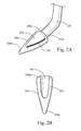
- Fig. 2A illustrates a perspective view of an exemplary retractor attached to another exemplary removable tip
- Fig. 2C illustrates a perspective view of the exemplary removable tip illustrated in Fig. 2A just prior to disengagement from the exemplary retractor
- Fig. 2D illustrates a perspective view of the exemplary removable tip illustrated in Fig. 2A disengaged from the distal-most portion of the exemplary retractor;
- Fig. 2E illustrates a perspective view of the exemplary removable tip illustrated in Fig. 2A being removed through an incision
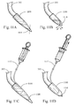
- Fig. 3A illustrates a perspective view of an exemplary retractor attached to another exemplary removable tip
- Fig. 3B illustrates a perspective view of the exemplary removable tip illustrated in Fig. 3A in the process of disengagement from the distal-most portion of the exemplary retractor;
- Fig. 3C illustrates a perspective view of the exemplary removable tip illustrated in Fig. 3A being disengaged from the distal-most portion of the exemplary retractor;
- Fig. 3D illustrates a perspective view of the exemplary removable tip illustrated in Fig. 3A being removed through an incision
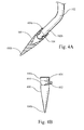
- Fig. 4A illustrates a perspective partial cross-sectional view of an exemplary retractor attached to another exemplary removable tip
- Fig. 4B illustrates a perspective view of the exemplary removable tip illustrated in Fig. 4A ;
- Fig. 4C illustrates a perspective view of the exemplary removable tip illustrated in Fig. 4A just prior to disengagement from the exemplary retractor
- Fig. 4D illustrates a perspective view of the exemplary removable tip illustrated in Fig. 4A disengaged from the exemplary retractor
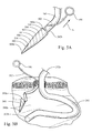
- Fig. 5A illustrates a perspective view of an exemplary retractor attached to another exemplary removable tip
- Fig. 5B illustrates a perspective view of the exemplary removable tip illustrated in Fig. 5A disengaged from the exemplary retractor
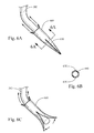
- Fig. 6A illustrates a perspective view of an exemplary retractor attached to another exemplary removable tip
- Fig. 6B is a cross-sectional view of the removable tip taken along line 6A-6A in Fig. 6A ;
- Fig. 6C illustrates a perspective view of the exemplary removable tip illustrated in Fig. 6A disengaged from the exemplary retractor
- Fig. 7A illustrates a perspective view of an exemplary retractor attached to another exemplary removable tip
- Fig. 7B illustrates a perspective view of the exemplary removable tip illustrated in Fig. 7A disengaged from the exemplary retractor
- Fig. 8A illustrates a perspective view of an exemplary retractor attached to another exemplary removable tip
- Figs. 8B-8E illustrate a perspective view of the exemplary removable tip illustrated in Fig. 8A partially or fully disengaged from the exemplary retractor;
- Fig. 9A illustrates a perspective view of an exemplary retractor attached to another exemplary removable tip
- Fig. 9B illustrates a perspective view of the exemplary removable tip illustrated in Fig. 9A in a collapsed configuration
- Figs. 9C-9E illustrate cross-sectional views of the exemplary removable tip illustrated in Fig. 9A showing the collapsing mechanism
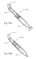
- Fig. 10A illustrates a perspective view of an exemplary retractor attached to another exemplary removable tip
- Fig. 10B illustrates a perspective view of the exemplary removable tip illustrated in Fig. 10A in a retracted position
- Figs. 10C-10E illustrate cross-sectional views of the exemplary removable tip illustrated in Fig. 10A comprising various retracting mechanisms
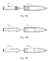
- Fig. 11A illustrates a perspective view of an exemplary retractor attached to another exemplary removable tip
- Fig. 11B illustrates a perspective view of the exemplary removable tip illustrated in Fig. 11A in a deflated configuration
- Figs. 11C-11D illustrate cross-sectional views of the exemplary removable tip illustrated in Fig. 11A further comprising an inflation mechanism
- Fig. 12B illustrates a perspective view of the exemplary removable tip illustrated in Fig. 12A in a partially retracted configuration
- Fig. 13A illustrates a perspective view of an exemplary retractor attached to another exemplary removable tip
- Fig. 13B illustrates a perspective view of the exemplary removable tip illustrated in Fig. 13A disengaged from the exemplary retractor
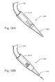
- Fig. 14A illustrates a perspective view of an exemplary retractor attached to another exemplary removable tip
- Fig. 14B illustrates a perspective view of the exemplary removable tip illustrated in Fig. 14A in a retracted configuration
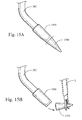
- Fig. 15A illustrates a perspective view of an exemplary retractor attached to another exemplary removable tip
- Fig. 16A illustrates a perspective partial cross-sectional view of an exemplary retractor attached to another exemplary removable tip
- Fig. 16B illustrates a perspective side view of the distal end of the exemplary removable tip illustrated in Fig. 16A ;
- Fig. 16C illustrates a perspective view of the exemplary removable tip illustrated in Fig. 16A disengaged from the exemplary retractor
- Fig. 17 illustrates a method of use of an exemplary retractor-removable tip system, such as those illustrated herein and equivalents thereto.
- the exemplary embodiments illustrated provide the discovery of systems, methods, and apparatuses used in conjunction with laparoscopic surgery to improve efficiency and navigation to the target anatomy while maintaining adequate exposure of the target anatomy.
- Diseases and conditions contemplated for treatment include, but are not limited to, those involving the pelvic region as well as any other bodily region or field benefiting from improved navigation to a target site.
- the present invention is not limited to those embodiments illustrated herein, but rather, the disclosure includes all equivalents including those of different shapes, sizes, and configurations.
- the systems, devices, and methods may be used in any field benefiting retractors or devices to aid in the navigation to a target site. Additionally, the devices and methods are not limited to being used with human beings; others are contemplated, including but not limited to, animals.
- proximal refers to a direction that is generally towards a physician during a medical procedure.
- Fig. 1A illustrates a perspective view of exemplary retractor 102 attached to exemplary removable tip 100
- Fig. 1B illustrates a perspective view of exemplary retractor 102 detached from exemplary removable tip 100
- Fig. 1C illustrates a perspective view of a portion of exemplary retractor 102 detached from exemplary removable tip 100 illustrated in Fig. 1B at the circle 1C.
- exemplary retractor 102 includes proximal portion 102a and distal portion 102b. The distal-most portion of retractor 102 has been modified to receive a female proximal portion 100a of removable tip 100.
- Retractor 102 is designed for insertion through a laparoscopic incision or port and is preferably used to aid in the positioning and or holding of organs or tissues during a diagnostic, exploratory, or therapy procedure.
- retractor 102 may be used to help position organs and tissues during, for example, rectal dissections, pelvic floor grafting, uterine procedures, and bowel procedures.
- two or more retractors 102 having removable tips 100 are contemplated.
- retractor 102 The distal-most end of retractor 102 is atraumatic, pinched, and tapered.
- Proximal portion 100a of removable tip 100 is substantially hollow to receive retractor 102 via a snap fit or other attachment means, including but not limited to, a friction fit.
- a screw/threaded attachment means may also be used, recognizing that such an attachment means may be more difficult to disengage when in use due to the space constraints of the working environment.
- Removable tip 100 is a substantially conical-shaped removable piece configured for attachment to distal portion 102b of retractor 102 to improve retractor 102 insertion, especially in the case of patients having large amounts of adipose tissue.
- Distal portion 100b of removable tip 100 is tapered and atraumatic for ease of insertion and navigation through an incision and to prevent damaging organs and tissue.
- retractor 102 may be configured to receive removable tip 100 therein.
- retractor 102 may be configured with a female distal end 102b into which a male proximal end 100a of removable tip 100 may be inserted and affixed thereto.
- a medical retractor be free from numerous crevasses or other surface features that may make sterilization for reuse difficult.
- removable tip 100 makes it easier for retractor 102 to be inserted through the incision during a laparoscopic procedure.
- the longer the removable tip 100 the more adipose tissue can be accommodated. In other words, fashioning removable tip 100 to have a longer dimension will allow it to accommodate thicker skin, fat, and muscle layers.
- removable tip 100 is removable from retractor 102 after retractor 102 is inserted, the space constraints addressed by a retractor 102 having a minimized overall size may be achieved.
- removable tip 100 is illustrated as disengaged from retractor 102 by being pulled distally from retractor 102, using, for example, an instrument such as endo grippers.
- retractor 102 alone is of a sufficient length to perform its retracting functions.
- the distal-most portion of retractor 102 includes a tapered atraumatic portion 104 for ease of insertion through an incision or port that will not damage tissue or organs once disengaged from removable tip 100.
- Removable tip 100 is approximately 5 cm long but other lengths are contemplated depending upon the amount of tissue needed through which to introduce retractor 102.
- removable tips 100 having a variety of lengths may be manufactured to accommodate various amounts of adipose or other tissues and could be provided as part of a kit.
- a first removable tip 100 may have a length of 5 cm
- a second may have a length of 8 cm
- a third may have a length of 10 cm. Accordingly, the user may choose the most appropriately-sized removable tip 100 for attachment to retractor 102 based on the clinical facts and circumstances. In some cases, if the material through which retractor 102 needs to be inserted is sufficiently thin, removable tip 100 may not be needed.
- Removable tip 100 is made from plastic, such as polypropylene, although other materials are contemplated, including but not limited to TPE (thermoplastic elastomers), polycarbonate, polystyrene, an elastomeric material capable of stretching over the distal-most portion of retractor 102, molded silicone, and metal.
- Removable tip 100 may be configured from two or more materials, including those having different properties, characteristics or features, including but not limited to, one material having a different hardness from the other.
- distal portion 100b of removable tip 100 may be configured from a harder material than, for example, proximal portion 100a of removable tip 100. The harder material may provide the distal portion 100b with an improved ability to pass through the tissue during placement, whereas the softer material may provide the proximal portion 100a with an improved ability to engage with the distal end 102b of the retractor 102.
- Removable tip 100 preferably is disposable, low-cost, and is intended for single use, although it may be configured to be reusable.
- Retractor 102 is preferably also low-cost and may be manufactured for either single use or for multiple uses.
- FIG. 2A illustrates a perspective view of exemplary retractor 202 attached to exemplary removable tip 200
- Fig. 2B illustrates a bottom perspective view of removable tip 200
- Fig. 2C illustrates a perspective view of removable tip 200 just prior to disengagement from retractor 202
- Fig. 2D illustrates a perspective view of removable tip 200 disengaged from the distal-most portion of retractor 202
- Fig. 2E illustrates a perspective view of removable tip 200 being removed through an incision.
- retractor 202 is similar to the retractor embodiment discussed above in connection with Figs. 1A-1C .
- the distal-most end of retractor 202 is atraumatic and rounded.
- retractor 202 is designed for insertion through a laparoscopic incision or port and is preferably used to aid in the positioning and or holding of organs or tissues during a diagnostic, exploratory, or therapy procedure.
- retractor 202 may be used to help position organs and tissues during, for example, rectal dissections, pelvic floor grafting, uterine procedures, and bowel procedures.
- the use of two or more retractors 202 having removable tips 200 is also contemplated.
- Removable tip 200 is a substantially conical-shaped removable piece configured for attachment to distal portion 202b of retractor 202 to improve the insertion capability of retractor 202, especially in the case of patients having large amounts of adipose tissue.
- Distal portion 200b of removable tip 200 is tapered and atraumatic for ease of insertion and navigation through an incision, as well as to prevent causing damage to organs and tissue.
- Proximal portion 200a of removable tip 200 is substantially hollow so as to receive retractor 202 therein.
- removable tip 200 is configured to be disengaged from retractor 202 by breaking the removable tip 200 at snap point 204. For example, referring to Fig.
- an instrument such as a forceps or endo gripper E is positioned at and grabs distal portion 200b of removable tip 200. Endo gripper E is then moved in the direction of arrow A to cause distal portion 200b of removable tip 200 to break from supporting neck 206 at snap point 204, thereby releasing the engagement of removable tip 200 with retractor 202.
- Removable tip 200 includes supporting neck 206 that maintains, at least temporarily, communication with retractor 202 even after distal portion 200b of removable tip 200 is broken at snap point 204.
- an instrument such as endo grippers E is used to back feed removable tip 200 proximally along retractor 202 in the direction of arrow B such that removable tip 200 is able to be removed from the area of the laparoscopic procedure.
- removable tip 200 continues to be back-thread proximally along retractor 202 in the direction of arrow C such that it is pushed through the incision point at the skin and the abdominal cavity, and is subsequently removed from the procedure.
- retractor 202 alone is of a sufficient length to perform its retracting functions.
- Removable tip 200 is approximately 5 cm long but other lengths are contemplated depending upon the amount of tissue through which retractor 202 is to be introduced.
- multiple removable tips 200 each having a variety of lengths may be manufactured to accommodate various amounts of adipose or other tissues.
- a first removable tip 200 may have a length of 5 cm
- a second may have a length of 8 cm
- a third may have a length of 10 cm.
- the removable tips 200 having various lengths may be included in a kit supplied with retractor 202. Accordingly, the user may choose the most appropriately-sized removable tip 200 for attachment to retractor 202 based on the clinical facts and circumstances. In some cases, the material through which retractor 202 needs to be inserted may be sufficiently thin such that removable tip 200 may not be needed.
- Removable tip 200 is made from plastic, such as polypropylene, although other materials are contemplated, including but not limited to TPE (thermoplastic elastomers), polycarbonate, polystyrene, nylon, and molded silicone.
- Removable tip 200 may be configured from two or more materials, including those having different properties, characteristics or features, including but not limited to, one having a different hardness from the other.
- distal portion 200b of removable tip 200 may be configured from a harder material than, for example, proximal portion 200a of removable tip 200.
- Removable tip 200 preferably is disposable, low-cost, and is intended for single use, although it may be configured to be reusable.
- Retractor 202 is preferably also low-cost and may be manufactured for single use or for multiple uses.
- removable tip 200 is never completely disengaged from the retractor 202 while within the patient. Accordingly, there is very little risk of removable tip 200 becoming lost or forgotten within the patient.
- Fig. 3A illustrates a perspective view of exemplary retractor 202 attached to exemplary removable tip 300
- Fig. 3B illustrates a perspective view of removable tip 300 in the process of disengagement from the distal-most portion of retractor 202
- Fig. 3C illustrates a perspective view of removable tip 300 being disengaged from the distal-most portion of retractor 202
- Fig. 3D illustrates a perspective view of removable tip 300 being removed through an incision.
- a single retractor 202 is illustrated, the use of two or more retractors 202 each having removable tips 300 is contemplated.
- Removable tip 300 includes proximal portion 300a and distal portion 300b.
- Removable tip 300 is a substantially conical-shaped removable piece configured for attachment to distal portion 202b of retractor 202 to improve retractor insertion, especially in the case of patients having large amounts of adipose tissue.
- proximal portion 300a of removable tip 300 is substantially hollow and configured for receiving distal portion 202b of retractor 202, via, for example, a snap fit or other attachment means, including but not limited to a friction fit.
- Distal portion 300b of removable tip 300 is tapered and atraumatic for ease of insertion and navigation through an incision and to prevent damaging organs and tissue.
- removable tip 300 includes pull cord 302 connected to ring 304 that when pulled, breaks removable tip 300 at perforations 308, thereby causing removable tip 300 to release its grip on retractor 202 such that removable tip 300 may be removed.
- Ring 304 or other retaining means is intended to remain outside patient while retractor 202 equipped with removable tip 300 is being inserted into a patient.
- ring 304 is pulled proximally in the direction of arrow F thereby causing perforations 308 (illustrated in Fig. 3A ) to break and create break flap 306 in the direction of arrow D.
- the entirety of tip 300 is then pulled proximally along retractor 202 in the direction of arrow G.
- removable tip 300 continues to be back-thread proximally along retractor 202 in the direction of arrow H such that it is pushed through the incision point at skin and the abdominal cavity and is able to be removed from the procedure.
- retractor 202 alone is of a sufficient length to perform its retracting functions.
- Removable tip 300 is approximately 15 cm long but other lengths are contemplated depending upon the amount of tissue needed through which to introduce retractor 202.
- multiple removable tips 300 having a variety of lengths may be manufactured to accommodate various amounts of adipose or other tissues.
- a first removable tip 300 may have a length of 15 cm, another may have a length of 18 cm, and another may have a length of 20 cm. Accordingly, the user may choose the most appropriately-sized removable tip 300 for attachment to retractor 202 based on the clinical facts and circumstances. In some cases, if the material through which retractor 202 needs to be inserted is sufficiently thin, removable tip 300 may not be needed.
- Removable tip 300 is made from plastic, such as polypropylene, although other materials are contemplated, including but not limited to TPE (thermoplastic elastomers), polycarbonate, polystyrene, nylon, and molded silicone.
- Removable tip 300 may be configured from two or more materials, including those having different characteristics or features, including but not limited to, one having a different hardness from the other.
- distal portion 300b of removable tip 300 may be configured from a harder material than, for example, proximal portion 300a of removable tip 300.
- Removable tip 300 preferably is disposable, low-cost, and is intended for single use, although it may be configured to be reusable.
- One advantage of the configuration of removable tip 300, among many, is that removable tip 300 is never completely disengaged from retractor 202 while within the patient. Accordingly, there is very little risk of removable tip 300 becoming lost or forgotten within the patient.
- Fig. 4A illustrates a perspective partial cross-sectional view of exemplary retractor 102 attached to exemplary removable tip 400
- Fig. 4B illustrates a perspective view of removable tip 400
- Fig. 4C illustrates a perspective view of removable tip 400 just prior to disengagement from the exemplary retractor
- Fig. 4D illustrates a perspective view of removable tip 400 disengaged from the exemplary retractor.
- the use of two or more retractors 102 having removable tips 400 are contemplated.
- removable tip 400 includes proximal portion 400a and distal portion 400b.
- Removable tip 400 is a substantially conical-shaped removable piece configured for attachment to distal portion 102b of retractor 102 to improve retractor insertion, especially in the case of patients having large amounts of adipose tissue.
- Distal portion 400b of removable tip 400 is tapered and atraumatic for ease of insertion and navigation through an incision and to prevent damaging organs and tissue.
- Proximal portion 400a of removable tip 400 is substantially hollow and configured for receiving distal portion 102b of retractor 102, via, for example, a snap fit or other attachment means, including but not limited to a friction fit.
- the distal portion 102b of the retractor 102 comprises one or more grooves or indentations that are configured to receive one or more ridges or protrusion on the inside of removable tip 400 to facilitate engagement between therebetween.
- Removable tip 400 includes pull tab 402 that when pulled, breaks removable tip 400 at perforations 404, thereby causing removable tip 400 to release its grip on retractor 102 such that removable tip 400 may be removed.
- an instrument such as a forceps or an endo gripper E is positioned at and grasps pull tab 402.
- the endo gripper E pulls pull tab 402 in the direction of arrow J away from removable tip 400, thereby causing perforations 404 to break until perforation stop 406 such that removable tip 400 remains one piece.
- Removable tip 400 is disengaged from retractor 102 and can be removed through any incision or port, or after the procedure is complete. Once removable tip 400 is disengaged from retractor 102, retractor 102 alone is of a sufficient length to perform its retracting functions.
- Removable tip 400 is approximately 5 cm long but other lengths are contemplated depending upon the amount of tissue needed through which to introduce retractor 102.
- multiple removable tips 400 having a variety of lengths may be manufactured to accommodate various amounts of adipose or other tissues.
- a first removable tip 400 may have a length of 5 cm, another may have a length of 8 cm, and another may have a length of 10 cm. Accordingly, the user may choose the most appropriately-sized removable tip 400 for attachment to retractor 102 based on the clinical facts and circumstances. In some cases, if the material through which retractor 102 needs to be inserted is sufficiently thin, removable tip 400 may not be needed.
- Removable tip 400 is made from plastic, such as polypropylene, although other materials are contemplated, including but not limited to TPE (thermoplastic elastomers), polycarbonate, polystyrene, nylon, and molded silicone.
- Removable tip 400 may be configured from two or more materials, including those having different characteristics or features, including but not limited to, one having a different hardness from the other.
- distal portion 400b of removable tip 400 may be configured from a harder material than, for example, proximal portion 400a of removable tip 400.
- Removable tip 400 preferably is disposable, low-cost, and is intended for single use, although it may be configured to be reusable.
- Fig. 5A illustrates a perspective view of exemplary retractor 202 attached to exemplary removable tip 500
- Fig. 5B illustrates a perspective view of removable tip 500 disengaged from exemplary retractor 202.
- the use of two or more retractors 202 having removable tips 500 are contemplated.
- Removable tip 500 includes proximal portion 500a and distal portion 500b.
- Removable tip 500 is a substantially conical-shaped removable piece configured for attachment to distal portion 202b of retractor 202 to improve retractor insertion, especially in the case of patients having large amounts of adipose tissue.
- Distal portion 500b of removable tip 500 is tapered and atraumatic for ease of insertion and navigation through an incision and to prevent damaging organs and tissue.
- Proximal portion 500a of removable tip 500 is substantially hollow and configured for receiving distal portion 202b of retractor 202.
- Removable tip 500 includes pull cord 502 connected to ring 506 that when pulled, breaks removable tip 500 at spiral perforations 504 disposed about removable tip 500, thereby causing removable tip 500 to unwind and release its grip on retractor 202 such that removable tip 500 may be removed.
- Ring 506 or other retaining means is intended to remain outside patient while retractor 202 equipped with removable tip 500 is being inserted into a patient.
- Ring 506 is pulled proximally in the direction of arrow K, thereby causing perforations 504 to break and unravel tip 500.
- the entirety of tip 500 is then pulled out of the way from the area of retractor 202.
- ring 506 or any portion of pull cord 502 may be taped, clipped, or adhered, to an article such as the skin's surface, to maintain the placement of removable tip 500.
- retractor 202 alone is of a sufficient length to perform its retracting functions. After retractor 202 is removed from the incision site, removable tip 500 is likewise able to be removed from the incision site.
- removable tip 500 is always connected to retractor 202 or the outside surface of the patient during the procedure. Accordingly, there is very little risk of removable tip 500 becoming lost or forgotten within the patient.
- Removable tip 500 is approximately 15 cm long but other lengths are contemplated depending upon the amount of tissue needed through which to introduce retractor 202.
- multiple removable tips 500 having a variety of lengths may be manufactured to accommodate various amounts of adipose or other tissues and provided with retractor 202 as a kit.
- a first removable tip 500 may have a length of 15 cm, another may have a length of 18 cm, and another may have a length of 20 cm. Accordingly, the user may choose from the kit the most appropriately-sized removable tip 500 for attachment to retractor 202 based on the clinical facts and circumstances. In some cases, if the material through which retractor 202 needs to be inserted is sufficiently thin, removable tip 500 may not be needed.
- Removable tip 500 is made from plastic, such as polypropylene, although other materials are contemplated, including but not limited to TPE (thermoplastic elastomers), polycarbonate, polystyrene, nylon, and molded silicone.
- Removable tip 500 may be configured from two or more materials, including those having different properties, characteristics or features, including but not limited to, one having a different hardness from the other.
- distal portion 500b of removable tip 500 may be configured from a harder material than, for example, proximal portion 500a of removable tip 500.
- Removable tip 500 preferably is disposable, low-cost, and is intended for single use, although it may be reusable.
- Figs. 6A-6C illustrate another embodiment of a removable tip 600 for use with retractor 202.
- the removable tip 600 comprises a pair of break lines 610 disposed longitudinally along the distal portion thereof.
- the break lines 610 are configured to break apart as the removable tip 600 is pulled in a proximal direction to thereby allow the removable tip 600 to be retracted in a proximal direction along the retractor 202.
- Pull tabs may be provided on the proximal end of the removable tip 600 to facilitate the application of the breaking force and removal of the removable tip 600.
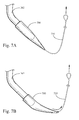
- Figs. 7A-7B illustrate another embodiment of a removable tip 700 for use with retractor 202.
- the removable tip 700 includes a pull cable 710 attached to the distal end the removable tip 700. Once the retractor 202 is position, the user pulls on the pull cable 710 with sufficient force to separate and remove the removable tip 700 from the retractor 202.
- the distal end of the pull cable 710 may include a loop to facilitate grasping thereof.
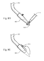
- Figs. 8A-8E illustrate another embodiment of a removable tip 800 for use with a retractor 202.
- the removable tip 800 comprises a foldable distal portion 810 that may be folded to either permit removal or reduce the overall length thereof.
- a forceps or endo grasper E is used to fold the distal portion 810.
- the folding of the distal portion 810 exposes an opening in the removable tip 800, thereby permitting the removable tip 800 to be retracted proximally along the retractor 202.
- the foldable distal portion 810 is folded and secured alongside the remaining portion of the removable tip 800, thereby reducing the overall length thereof.
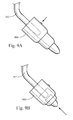
- Figs. 9A-9E illustrate another embodiment of a removable tip 900 for use with a retractor 202.
- the removable tip 900 comprises a collapsing mechanism 910 that permits the overall length of the removable tip 900 to be reduced.
- the collapsing mechanism 910 comprises a plurality of interior supports that are secured to telescoping portions of the removable tip 900.
- a button or other activation device on the removable tip 900 is depressed to break the interior supports, thereby allowing the telescoping sections to be collapsed, as shown in Fig. 9B .
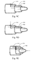
- Figs. 10A-10E illustrate another embodiment of a removable tip 1000 for use with a retractor 202.
- the removable tip 1000 comprises a retracting mechanism that permits the overall length of the removable tip 1000 to be reduced.
- the retracting mechanism includes a screw thread disposed on the outer surface of proximal portion 1010 which is configured to mate with a screw thread on the internal surface of distal portion 1012. Rotation of the distal portion 1012 relative to the proximal portion 1010 causes the distal portion to move in a proximal direction relative to the retractor 202, thereby allowing the overall length of the removable tip 1000 to be reduced.
- proximal portion 1010 is a separate component that is affixed to the distal end of the retractor 202.
- the proximal portion 1010 could be integrally formed with or a formed into the distal end of the retractor 202.
- Figs. 11A-11D illustrate another embodiment of a removable tip 1100 for use with a retractor 202.
- the removable tip 1100 comprises an inflatable balloon tip 1110 that is filled with saline. The saline is removed from the balloon tip 1110 to deflate and collapse the balloon tip 1110, thereby reducing the overall length of the removable tip 1100.
- the balloon tip 1110 is cut or punctured to allow the saline to escape.
- the removable tip 1100 further includes an inflation mechanism 1112 for delivering saline to or removing saline from the balloon tip 1110.
- the balloon tip 1110 could comprise multiple chambers to allow removable tip 1100 to be inflated to various lengths or configuration.
- Figs. 12A-12B illustrate another embodiment of a removable tip 1200 for use with a retractor 202.
- the removable tip 1200 comprises a deformable and/or compressible material.
- a pull cable 1210 is attached the distal end of the removable tip 1200.
- the pull cable 1210 passes proximally through a lumen or hollowed out portion of the removable tip 1200, and then proximally through a lumen of the retractor 202. Once the retractor 202 is in position, the used pulls the pull cable 1210 to invert the distal end of the removable tip 1200.
- the distal end of the removable tip 1200 is then pulled back into the lumen or hollowed out portion of the removable tip 1200, thereby reducing the overall length of the removable tip 1200.
- the distal portion of the removable tip 1200 is also pulled into the lumen of the retractor 202. If the removable tip 1200 comprises a sufficiently compressible material, the removable tip may be pulled completely into the lumen of the retractor 202.
- Figs. 13A-13B illustrate another embodiment of a removable tip 1300 for use with retractor 202.
- the removable tip 1300 includes a grasping mechanism 1310 attached to the distal end the removable tip 1300.
- the grasping mechanism 1310 comprises a port in the distal end of the removable tip 1300.
- other grasping mechanisms are contemplated, such a wire ring or suture loop.
- Figs. 14A-14B illustrate another embodiment of a removable tip 1400 for use with a retractor 202.
- the removable tip 1400 comprises a spring loaded retracting mechanism that permits the overall length of the removable tip 1400 to be reduced.
- the removable tip 1400 comprises a distal portion 1410 that is slidably coupled to a proximal portion 1412, wherein a coil spring is disposed therebetween.
- a detent or similar mechanism may be provided between the distal portion 1410 and the proximal portion 1412 to secure the removable tip 1400 in a collapsed configuration.
- the proximal portion 1412 is a separate component that is affixed to the distal end of the retractor 202.
- the proximal portion 1412 could be integrally formed with or a formed into the distal end of the retractor 202.
- Figs. 15A-15B illustrate another embodiment of a removable tip 1500 for use with a retractor 202.
- the removable tip 1500 comprises a distal end portion 1510 that is removable.
- the distal end portion 1510 is cut and removed from the removable tip 1500 once the retractor 202 is in position.
- the distal end portion 1510 may also be snapped off and removed.
- the removable tip 1500 may comprise a weakened area configured to facilitate removal of the distal end portion 1510.
- a forceps or endo grasper E may be used to remove the distal end portion 1510 from the surgical site.
- Figs. 16A-16C illustrate another embodiment of a removable tip 1600 for use with retractor 102 and is similar to the embodiment discussed above in connection with Figs. 4A-4D .
- Fig. 16A illustrates a perspective partial cross-sectional view of exemplary retractor 102 attached to exemplary removable tip 1600
- Fig. 16B illustrates a perspective view of the distal end portion of the removable tip 1600
- Fig. 16C illustrates a perspective view of removable tip 1600 disengaged from the exemplary retractor.
- removable tip 1600 includes proximal portion 1600a and distal portion 1600b.
- Removable tip 1600 is a substantially conical-shaped removable piece configured for attachment to distal portion 102b of retractor 102 to improve retractor insertion, especially in the case of patients having large amounts of adipose tissue.
- distal portion 1600b of removable tip 1600 comprises a flattened end portion having a reduced cross-section for ease of insertion and navigation through an incision and to prevent damaging organs and tissue. The reduced cross-section also facilitates grasping by a forceps or other device.
- Distal portion 1600b may also include a opening for the attachment of a suture or pull wire.
- proximal portion 1600a of removable tip 1600 is substantially hollow and configured for receiving distal portion 102b of retractor 102, via, for example, a snap fit or other attachment means, including but not limited to a friction fit.
- the distal portion 102b of the retractor 102 comprises one or more grooves or indentations that are configured to receive one or more ridges or protrusion on the inside of removable tip 1600 to facilitate engagement between therebetween.
- removable tip 1600 includes pull tab 1602 that when pulled, breaks removable tip 1600 at perforations 1604, thereby causing removable tip 1600 to release its grip on retractor 102 such that removable tip 1600 may be removed.
- the pull tab 1602 can be grasped with a forceps or endo gripper, and then pulled away from removable tip 1600 to thereby cause perforations 1604 to break.
- Removable tip 1600 can then be disengaged from the retractor 102 and removed through an incision or port, or after the procedure is complete. Once removable tip 1600 is disengaged from retractor 102, retractor 102 alone is of a sufficient length to perform its retracting functions.
- Fig. 17 illustrates a method 1700 of use of an exemplary retractor-removable tip system, such as those illustrated herein and equivalents thereto.
- a retractor is provided, such as those illustrated in Figs. 1A-16C or equivalents thereto.
- a removable tip is provided, such as those illustrated in Figs. 1A-16C or equivalents thereto.
- the removable tip is attached to the retractor forming an assembly. Attachment means include, but are not limited to a snap fit, friction fit, and a screw/threaded attachment.
- the assembly is inserted through an incision or a port.
- the removable tip is disengaged from the retractor by a disengagement means, such as those illustrated in Figs. 1A-16C , including but not limited to, pulling the removable tip distally from the retractor, snapping a distal portion of the tip breaking the supporting neck, pulling a pull cord or pull tab causing the removable tip to break at perforations.
- the removable tip is removed from the incision or port, which may be the same incision or port illustrated at block 1608.
- the removable tip may be removed before or after removing the retractor from an incision or port.
- Means for removing the removable tip from an incision or a port include, but are not limited to, those illustrated in Figs.
Abstract
Description
- The present invention relates to medical devices and more specifically, instruments used in conjunction with laparoscopic surgery.
- Laparoscopic surgical procedures generally involve inflating a bodily cavity with a gas, such as the abdomen, to provide better visibility of the surgical site. Such gasses may include carbon dioxide. After the surgical site is insufflated, the bodily cavity may be punctured using a trocar device for the purposes of inserting surgical tools such as a laparoscopic camera, cutting and manipulating tools, etc. For example, when performing laparoscopic surgery in the abdominal area, the trocar device is utilized to puncture the peritoneum. Thereafter, a laparoscopic retractor may be inserted through the puncture site and directed to the targeted anatomy to assist in retracting and holding certain bodily organs and tissue, thereby exposing the surgical field for the procedure. Maintaining adequate vision of the target or surgical field during laparoscopic procedures is critical to a successful laparoscopic procedure, as inadequate ability to visualize anatomical structures is a common complication of laparoscopic procedures, and can lead to conversion from a laparoscopic to an open procedure.
- Laparoscopic surgery has many advantages over traditional open surgery in that it generally takes less time to complete, the patient is likely to experience less severe post-operative pain, and the incisions leave less noticeable scarring as compared to open surgery. Additionally, hospital recovery time and costs are generally reduced.
- Despite the benefits of laparoscopic surgery, such surgery is often difficult to perform due to the effort required to arrive at adequate exposure of the surgical field. This is especially true in the case of inserting a retractor into a larger patient due to, for example, the distribution of adipose tissue over the preferred insertion site. For example, after the initial insertion is made, the retractor must be navigated through numerous layers of materials, including the skin, adipose tissue, etc. to reach the abdominal cavity and from there the target anatomy site. The materials through which the retractor is navigated are malleable and flexible, and accordingly, the incision does not remain fixed relative to the skin, adipose tissue, etc. Thus, inserting the retractor through the layers of material, especially when the patient has a thicker layer of adipose tissue over the insertion site, is difficult and results in a phenomenon called "tenting", wherein the retractor becomes stuck in the layers of material that have moved relative to the insertion point. This delays the procedure until the end of the retractor finally locates the incision into the abdominal cavity. Because laparoscopic retractors typically have a rounded end to facilitate easy insertion though the skin and into the abdominal cavity, the length of the end dictates how much adipose tissue can be accommodated. The more the adipose layers must be compressed to insert the insertion end, the more likely the incision path becomes difficult to navigate. Although the insertion end of the retractor could be lengthened, a long retractor end impedes the medical procedure once it has been inserted, particularly in surgical areas having space constraints such as the pelvic area. Accordingly, present retractors do not provide an adequate solution to performing efficient laparoscopic surgery on those patients with additional adipose tissue over the preferred insertion site.
- In a first aspect, a removable tip is provided comprising a substantially conical-shaped body comprising a proximal body portion and a distal body portion, wherein the proximal body portion comprises a substantially hollow portion and is configured for receiving a distal portion of a medical retractor, and wherein the distal body portion is atraumatic.
- In some embodiments, when said proximal body portion is engaged with said distal portion of a medical retractor, said distal body portion may be movable relative to said proximal body portion and to said distal portion of said medical retractor, such that a passageway of sufficient size to accommodate said distal portion of said medical retractor is opened in said conical-shaped body and such that said removable tip may thereafter slide along the length of the medical retractor, with the medical retractor being accommodated in said passageway. Suitably, the removable tip comprises a disengagement means that is actuable to cause said moment of said distal body portion relative to said proximal body portion and to said distal portion of said medical retractor. The opening of a passageway of sufficient size to accommodate said distal portion of said medical retractor may include the enlargement of an existing passageway to a sufficient size to accommodate said distal portion of said medical retractor, or may include a snap point breaking a portion of a supporting neck disposed between the proximal body portion and the distal body portion. Suitably, said passageway may be opened by the tearing of a region of weakness in said conical-shaped body. In some embodiments, said passageway may be opened by the tearing of two regions of weakness, or a plurality of regions of weakness. Suitably, the or each region of weakness may comprise a plurality of perforations disposed on the substantially conical-shaped body. Such perforations may be disposed longitudinally along, circumferentially around, or spirally about the conical-shaped body. Alternatively, or in addition, the or each region of weakness may comprise a break line, which may suitably be disposed longitudinally. In some embodiments, the removable tip may comprise disengagement means actuable to transform said conical-shaped body into a sliding configuration, wherein said conical-shaped body may slide along the length of said medical retractor. In other embodiments, the removable tip may comprise disengagement means comprising one or more regions of weakness (including any of the features above) that may be torn so as to allow said removable tip to disengage from said distal portion of said medical retractor. Suitably, a pull cord may be attached to the distal or proximal end of said conical-shaped body so as to enable the tearing of said region(s) of weakness. More generally, a pull cord may be attached to the distal or proximal end of said conical-shaped body so as to enable the removable tip to disengage from said distal portion of said medical retractor.
- In a second aspect, a medical retractor system is provided, comprising a removable tip having a substantially conical-shaped body comprising a proximal body portion and a distal body portion, wherein the proximal body portion comprises a substantially hollow portion and is configured for receiving a distal portion of a medical retractor, and wherein the distal body portion is atraumatic; a disengagement means in communication with the substantially conical-shaped body configured to disengage the substantially conical-shaped body from a distal portion of a medical retractor; and a medical retractor having a proximal portion and a distal portion, wherein the distal portion is connected to the removable tip.
- In some embodiments, the disengagement means may be actuable to move said distal body portion relative to said proximal body portion and to said distal portion of said medical retractor, such that a passageway of sufficient size to accommodate said distal portion of said medical retractor is opened in said conical-shaped body and such that said removable tip may thereafter slide along the length of the medical retractor, preferably wherein said passageway is opened by the tearing of a region of weakness in said conical-shaped body. The opening of a passageway of sufficient size to accommodate said distal portion of said medical retractor may include the enlargement of an existing passageway to a sufficient size to accommodate said distal portion of said medical retractor, or may include a snap point breaking a portion of a supporting neck disposed between the proximal body portion and the distal body portion. Suitably, said passageway may be opened by the tearing of a region of weakness in said conical-shaped body. In some embodiments, said passageway may be opened by the tearing of two regions of weakness, or a plurality of regions of weakness. Suitably, the or each region of weakness may comprise a plurality of perforations disposed on the substantially conical-shaped body. Such perforations may be disposed longitudinally along, circumferentially around, or spirally about the conical-shaped body. Alternatively, or in addition, the or each region of weakness may comprise a break line, which may suitably be disposed longitudinally. Suitably, the medical retractor system may comprise a plurality of removable tips of different sizes or, more specifically, of different overall lengths. In some embodiments, the removable tip may comprise disengagement means actuable to transform said conical-shaped body into a sliding configuration, wherein said conical-shaped body may slide along the length of said medical retractor. In other embodiments, the removable tip may comprise disengagement means comprising one or more regions of weakness (including any of the features above) that may be torn so as to allow said removable tip to disengage from said distal portion of said medical retractor. Suitably, a pull cord may be attached to the distal or proximal end of said conical-shaped body so as to enable the tearing of said region(s) of weakness. More generally, a pull cord may be attached to the distal or proximal end of the conical-shaped body so as to enable the removable tip to disengage from said distal portion of said medical retractor.
- In a third aspect, a method for using a medical retractor system is provided, comprising the steps of providing a medical retractor comprising a proximal portion and a distal portion; and providing a removable tip comprising a substantially conical-shaped body comprising a proximal body portion and a distal body portion, wherein the proximal body portion comprises a substantially hollow portion and is configured for receiving the distal portion of the medical retractor, and wherein the distal body portion is atraumatic.
- In some embodiments, a plurality of removable tips of different sizes may be provided, the method suitably further comprising selecting an appropriately-sized one of said removable tips based on the clinical facts and circumstances. The plurality of removable tips of different sizes may more specifically be of different overall lengths.
- The embodiments will be further described in connection with the attached drawing figures. It is intended that the drawings included as a part of this specification be illustrative of the exemplary embodiments and should in no way be considered as a limitation on the scope of the invention. Indeed, the present disclosure specifically contemplates other embodiments not illustrated but intended to be included in the claims. Moreover, it is understood that the figures are not necessarily drawn to scale.
-
Fig. 1A illustrates a perspective view of an exemplary retractor attached to an exemplary removable tip; -
Fig. 1B illustrates a perspective view of the exemplary retractor detached from the exemplary removable tip illustrated inFig. 1A ; -
Fig. 1C illustrates a perspective view of a portion of the exemplary retractor detached from the exemplary removable tip illustrated inFig. 1B at thecircle 1C; -
Fig. 2A illustrates a perspective view of an exemplary retractor attached to another exemplary removable tip; -
Fig. 2B illustrates a bottom perspective view of the exemplary removable tip illustrated inFig. 2A ; -
Fig. 2C illustrates a perspective view of the exemplary removable tip illustrated inFig. 2A just prior to disengagement from the exemplary retractor; -
Fig. 2D illustrates a perspective view of the exemplary removable tip illustrated inFig. 2A disengaged from the distal-most portion of the exemplary retractor; -
Fig. 2E illustrates a perspective view of the exemplary removable tip illustrated inFig. 2A being removed through an incision; -
Fig. 3A illustrates a perspective view of an exemplary retractor attached to another exemplary removable tip; -
Fig. 3B illustrates a perspective view of the exemplary removable tip illustrated inFig. 3A in the process of disengagement from the distal-most portion of the exemplary retractor; -
Fig. 3C illustrates a perspective view of the exemplary removable tip illustrated inFig. 3A being disengaged from the distal-most portion of the exemplary retractor; -
Fig. 3D illustrates a perspective view of the exemplary removable tip illustrated inFig. 3A being removed through an incision; -
Fig. 4A illustrates a perspective partial cross-sectional view of an exemplary retractor attached to another exemplary removable tip; -
Fig. 4B illustrates a perspective view of the exemplary removable tip illustrated inFig. 4A ; -
Fig. 4C illustrates a perspective view of the exemplary removable tip illustrated inFig. 4A just prior to disengagement from the exemplary retractor; -
Fig. 4D illustrates a perspective view of the exemplary removable tip illustrated inFig. 4A disengaged from the exemplary retractor; -
Fig. 5A illustrates a perspective view of an exemplary retractor attached to another exemplary removable tip; -
Fig. 5B illustrates a perspective view of the exemplary removable tip illustrated inFig. 5A disengaged from the exemplary retractor; -
Fig. 6A illustrates a perspective view of an exemplary retractor attached to another exemplary removable tip; -
Fig. 6B is a cross-sectional view of the removable tip taken alongline 6A-6A inFig. 6A ; -
Fig. 6C illustrates a perspective view of the exemplary removable tip illustrated inFig. 6A disengaged from the exemplary retractor; -
Fig. 7A illustrates a perspective view of an exemplary retractor attached to another exemplary removable tip; -
Fig. 7B illustrates a perspective view of the exemplary removable tip illustrated inFig. 7A disengaged from the exemplary retractor; -
Fig. 8A illustrates a perspective view of an exemplary retractor attached to another exemplary removable tip; -
Figs. 8B-8E illustrate a perspective view of the exemplary removable tip illustrated inFig. 8A partially or fully disengaged from the exemplary retractor; -
Fig. 9A illustrates a perspective view of an exemplary retractor attached to another exemplary removable tip; -
Fig. 9B illustrates a perspective view of the exemplary removable tip illustrated inFig. 9A in a collapsed configuration; -
Figs. 9C-9E illustrate cross-sectional views of the exemplary removable tip illustrated inFig. 9A showing the collapsing mechanism; -
Fig. 10A illustrates a perspective view of an exemplary retractor attached to another exemplary removable tip; -
Fig. 10B illustrates a perspective view of the exemplary removable tip illustrated inFig. 10A in a retracted position; -
Figs. 10C-10E illustrate cross-sectional views of the exemplary removable tip illustrated inFig. 10A comprising various retracting mechanisms; -
Fig. 11A illustrates a perspective view of an exemplary retractor attached to another exemplary removable tip; -
Fig. 11B illustrates a perspective view of the exemplary removable tip illustrated inFig. 11A in a deflated configuration; -
Figs. 11C-11D illustrate cross-sectional views of the exemplary removable tip illustrated inFig. 11A further comprising an inflation mechanism; -
Fig. 12A illustrates a perspective view of an exemplary retractor attached to another exemplary removable tip; -
Fig. 12B illustrates a perspective view of the exemplary removable tip illustrated inFig. 12A in a partially retracted configuration; -
Fig. 13A illustrates a perspective view of an exemplary retractor attached to another exemplary removable tip; -
Fig. 13B illustrates a perspective view of the exemplary removable tip illustrated inFig. 13A disengaged from the exemplary retractor; -
Fig. 14A illustrates a perspective view of an exemplary retractor attached to another exemplary removable tip; -
Fig. 14B illustrates a perspective view of the exemplary removable tip illustrated inFig. 14A in a retracted configuration; -
Fig. 15A illustrates a perspective view of an exemplary retractor attached to another exemplary removable tip; -
Fig. 15B illustrates a perspective view of the exemplary removable tip illustrated inFig. 15A in a shortened configuration; -
Fig. 16A illustrates a perspective partial cross-sectional view of an exemplary retractor attached to another exemplary removable tip; -
Fig. 16B illustrates a perspective side view of the distal end of the exemplary removable tip illustrated inFig. 16A ; -
Fig. 16C illustrates a perspective view of the exemplary removable tip illustrated inFig. 16A disengaged from the exemplary retractor; and -
Fig. 17 illustrates a method of use of an exemplary retractor-removable tip system, such as those illustrated herein and equivalents thereto. - The exemplary embodiments illustrated provide the discovery of systems, methods, and apparatuses used in conjunction with laparoscopic surgery to improve efficiency and navigation to the target anatomy while maintaining adequate exposure of the target anatomy.
- Diseases and conditions contemplated for treatment include, but are not limited to, those involving the pelvic region as well as any other bodily region or field benefiting from improved navigation to a target site.
- The present invention is not limited to those embodiments illustrated herein, but rather, the disclosure includes all equivalents including those of different shapes, sizes, and configurations. The systems, devices, and methods may be used in any field benefiting retractors or devices to aid in the navigation to a target site. Additionally, the devices and methods are not limited to being used with human beings; others are contemplated, including but not limited to, animals.
- Unless otherwise defined, all technical and scientific terms used herein have the same meaning as commonly understood by one of ordinary skill in the art. In case of conflict, the present document, including definitions, will control. Preferred methods and materials are illustrated below, although apparatuses, methods, and materials similar or equivalent to those illustrated herein may be used in practice or testing. All publications, patent applications, patents and other references mentioned herein are incorporated by reference in their entirety. The materials, methods, and examples disclosed herein are illustrative only and not intended to be limiting.
- The terms "comprise(s)," "include(s)," "having," "has," "can," "contain(s)," and variants thereof, as used herein, are intended to be open-ended transitional phrases, terms, or words that do not preclude the possibility of additional acts or structures. The present disclosure also contemplates other embodiments "comprising," "consisting of" and "consisting essentially of," the embodiments or elements presented herein, whether explicitly set forth or not.
- The term "proximal," as used herein, refers to a direction that is generally towards a physician during a medical procedure.
- The term "distal," as used herein, refers to a direction that is generally towards a target site within a patient's anatomy during a medical procedure.
- A more detailed description of the embodiments will now be given with reference to
Figs. 1A-17 . Throughout the disclosure, like reference numerals and letters refer to like elements. The present disclosure is not limited to the embodiments illustrated; to the contrary, the present disclosure specifically contemplates other embodiments not illustrated but intended to be included in the claims. -
Fig. 1A illustrates a perspective view ofexemplary retractor 102 attached to exemplaryremovable tip 100,Fig. 1B illustrates a perspective view ofexemplary retractor 102 detached from exemplaryremovable tip 100, andFig. 1C illustrates a perspective view of a portion ofexemplary retractor 102 detached from exemplaryremovable tip 100 illustrated inFig. 1B at thecircle 1C. Referring toFig. 1A ,exemplary retractor 102 includesproximal portion 102a anddistal portion 102b. The distal-most portion ofretractor 102 has been modified to receive a femaleproximal portion 100a ofremovable tip 100.Retractor 102 is designed for insertion through a laparoscopic incision or port and is preferably used to aid in the positioning and or holding of organs or tissues during a diagnostic, exploratory, or therapy procedure. For example,retractor 102 may be used to help position organs and tissues during, for example, rectal dissections, pelvic floor grafting, uterine procedures, and bowel procedures. Moreover the use of two ormore retractors 102 havingremovable tips 100 are contemplated. - The distal-most end of
retractor 102 is atraumatic, pinched, and tapered.Proximal portion 100a ofremovable tip 100 is substantially hollow to receiveretractor 102 via a snap fit or other attachment means, including but not limited to, a friction fit. A screw/threaded attachment means may also be used, recognizing that such an attachment means may be more difficult to disengage when in use due to the space constraints of the working environment. -
Removable tip 100 is a substantially conical-shaped removable piece configured for attachment todistal portion 102b ofretractor 102 to improveretractor 102 insertion, especially in the case of patients having large amounts of adipose tissue.Distal portion 100b ofremovable tip 100 is tapered and atraumatic for ease of insertion and navigation through an incision and to prevent damaging organs and tissue. Althoughremovable tip 100 is illustrated as being configured to receiveretractor 102 therein,retractor 102 may be configured to receiveremovable tip 100 therein. In other words,retractor 102 may be configured with a femaledistal end 102b into which a maleproximal end 100a ofremovable tip 100 may be inserted and affixed thereto. In any event, in either configuration, it is generally preferred, although not required, that a medical retractor be free from numerous crevasses or other surface features that may make sterilization for reuse difficult. - The additional overall length provided by
removable tip 100 makes it easier forretractor 102 to be inserted through the incision during a laparoscopic procedure. The longer theremovable tip 100, the more adipose tissue can be accommodated. In other words, fashioningremovable tip 100 to have a longer dimension will allow it to accommodate thicker skin, fat, and muscle layers. However, becauseremovable tip 100 is removable fromretractor 102 afterretractor 102 is inserted, the space constraints addressed by aretractor 102 having a minimized overall size may be achieved. - Referring to
Figs. 1B and1C ,removable tip 100 is illustrated as disengaged fromretractor 102 by being pulled distally fromretractor 102, using, for example, an instrument such as endo grippers. Onceremovable tip 100 is disengaged fromretractor 102,retractor 102 alone is of a sufficient length to perform its retracting functions. The distal-most portion ofretractor 102 includes a taperedatraumatic portion 104 for ease of insertion through an incision or port that will not damage tissue or organs once disengaged fromremovable tip 100. -
Removable tip 100 is approximately 5 cm long but other lengths are contemplated depending upon the amount of tissue needed through which to introduceretractor 102. For example,removable tips 100 having a variety of lengths may be manufactured to accommodate various amounts of adipose or other tissues and could be provided as part of a kit. For example, a firstremovable tip 100 may have a length of 5 cm, a second may have a length of 8 cm, and a third may have a length of 10 cm. Accordingly, the user may choose the most appropriately-sizedremovable tip 100 for attachment to retractor 102 based on the clinical facts and circumstances. In some cases, if the material through whichretractor 102 needs to be inserted is sufficiently thin,removable tip 100 may not be needed. -
Removable tip 100 is made from plastic, such as polypropylene, although other materials are contemplated, including but not limited to TPE (thermoplastic elastomers), polycarbonate, polystyrene, an elastomeric material capable of stretching over the distal-most portion ofretractor 102, molded silicone, and metal.Removable tip 100 may be configured from two or more materials, including those having different properties, characteristics or features, including but not limited to, one material having a different hardness from the other. For example,distal portion 100b ofremovable tip 100 may be configured from a harder material than, for example,proximal portion 100a ofremovable tip 100. The harder material may provide thedistal portion 100b with an improved ability to pass through the tissue during placement, whereas the softer material may provide theproximal portion 100a with an improved ability to engage with thedistal end 102b of theretractor 102. -
Removable tip 100 preferably is disposable, low-cost, and is intended for single use, although it may be configured to be reusable.Retractor 102 is preferably also low-cost and may be manufactured for either single use or for multiple uses. -
Fig. 2A illustrates a perspective view ofexemplary retractor 202 attached to exemplaryremovable tip 200,Fig. 2B illustrates a bottom perspective view ofremovable tip 200,Fig. 2C illustrates a perspective view ofremovable tip 200 just prior to disengagement fromretractor 202,Fig. 2D illustrates a perspective view ofremovable tip 200 disengaged from the distal-most portion ofretractor 202, andFig. 2E illustrates a perspective view ofremovable tip 200 being removed through an incision. Referring toFigs. 2A-2B ,retractor 202 is similar to the retractor embodiment discussed above in connection withFigs. 1A-1C . The distal-most end ofretractor 202 is atraumatic and rounded. For example,retractor 202 is designed for insertion through a laparoscopic incision or port and is preferably used to aid in the positioning and or holding of organs or tissues during a diagnostic, exploratory, or therapy procedure. For example,retractor 202 may be used to help position organs and tissues during, for example, rectal dissections, pelvic floor grafting, uterine procedures, and bowel procedures. Although only asingle retractor 202 is illustrated, the use of two ormore retractors 202 havingremovable tips 200 is also contemplated. -
Removable tip 200 is a substantially conical-shaped removable piece configured for attachment todistal portion 202b ofretractor 202 to improve the insertion capability ofretractor 202, especially in the case of patients having large amounts of adipose tissue.Distal portion 200b ofremovable tip 200 is tapered and atraumatic for ease of insertion and navigation through an incision, as well as to prevent causing damage to organs and tissue.Proximal portion 200a ofremovable tip 200 is substantially hollow so as to receiveretractor 202 therein. As will be explained below,removable tip 200 is configured to be disengaged fromretractor 202 by breaking theremovable tip 200 atsnap point 204. For example, referring toFig. 2C , an instrument, such as a forceps or endo gripper E is positioned at and grabsdistal portion 200b ofremovable tip 200. Endo gripper E is then moved in the direction of arrow A to causedistal portion 200b ofremovable tip 200 to break from supportingneck 206 atsnap point 204, thereby releasing the engagement ofremovable tip 200 withretractor 202.Removable tip 200 includes supportingneck 206 that maintains, at least temporarily, communication withretractor 202 even afterdistal portion 200b ofremovable tip 200 is broken atsnap point 204. - Referring to
Fig. 2D , an instrument, such as endo grippers E is used to back feedremovable tip 200 proximally alongretractor 202 in the direction of arrow B such thatremovable tip 200 is able to be removed from the area of the laparoscopic procedure. Referring toFig. 2E ,removable tip 200 continues to be back-thread proximally alongretractor 202 in the direction of arrow C such that it is pushed through the incision point at the skin and the abdominal cavity, and is subsequently removed from the procedure. Onceremovable tip 200 is disengaged fromretractor 202,retractor 202 alone is of a sufficient length to perform its retracting functions. -
Removable tip 200 is approximately 5 cm long but other lengths are contemplated depending upon the amount of tissue through whichretractor 202 is to be introduced. For example, multipleremovable tips 200 each having a variety of lengths may be manufactured to accommodate various amounts of adipose or other tissues. For example, a firstremovable tip 200 may have a length of 5 cm, a second may have a length of 8 cm, and a third may have a length of 10 cm. Theremovable tips 200 having various lengths may be included in a kit supplied withretractor 202. Accordingly, the user may choose the most appropriately-sizedremovable tip 200 for attachment to retractor 202 based on the clinical facts and circumstances. In some cases, the material through whichretractor 202 needs to be inserted may be sufficiently thin such thatremovable tip 200 may not be needed. -
Removable tip 200 is made from plastic, such as polypropylene, although other materials are contemplated, including but not limited to TPE (thermoplastic elastomers), polycarbonate, polystyrene, nylon, and molded silicone.Removable tip 200 may be configured from two or more materials, including those having different properties, characteristics or features, including but not limited to, one having a different hardness from the other. For example,distal portion 200b ofremovable tip 200 may be configured from a harder material than, for example,proximal portion 200a ofremovable tip 200. -
Removable tip 200 preferably is disposable, low-cost, and is intended for single use, although it may be configured to be reusable.Retractor 202 is preferably also low-cost and may be manufactured for single use or for multiple uses. - One advantage of the configuration of
removable tip 200, among many, is thatremovable tip 200 is never completely disengaged from theretractor 202 while within the patient. Accordingly, there is very little risk ofremovable tip 200 becoming lost or forgotten within the patient. -
Fig. 3A illustrates a perspective view ofexemplary retractor 202 attached to exemplaryremovable tip 300,Fig. 3B illustrates a perspective view ofremovable tip 300 in the process of disengagement from the distal-most portion ofretractor 202,Fig. 3C illustrates a perspective view ofremovable tip 300 being disengaged from the distal-most portion ofretractor 202, andFig. 3D illustrates a perspective view ofremovable tip 300 being removed through an incision. Although asingle retractor 202 is illustrated, the use of two ormore retractors 202 each havingremovable tips 300 is contemplated. -
Removable tip 300 includesproximal portion 300a anddistal portion 300b.Removable tip 300 is a substantially conical-shaped removable piece configured for attachment todistal portion 202b ofretractor 202 to improve retractor insertion, especially in the case of patients having large amounts of adipose tissue. Referring toFig. 3A ,proximal portion 300a ofremovable tip 300 is substantially hollow and configured for receivingdistal portion 202b ofretractor 202, via, for example, a snap fit or other attachment means, including but not limited to a friction fit.Distal portion 300b ofremovable tip 300 is tapered and atraumatic for ease of insertion and navigation through an incision and to prevent damaging organs and tissue. In this particular embodiment,removable tip 300 includespull cord 302 connected to ring 304 that when pulled, breaksremovable tip 300 atperforations 308, thereby causingremovable tip 300 to release its grip onretractor 202 such thatremovable tip 300 may be removed.Ring 304 or other retaining means is intended to remain outside patient whileretractor 202 equipped withremovable tip 300 is being inserted into a patient. - Referring to
Figs. 3B and3C ,ring 304 is pulled proximally in the direction of arrow F thereby causing perforations 308 (illustrated inFig. 3A ) to break and createbreak flap 306 in the direction of arrow D. The entirety oftip 300 is then pulled proximally alongretractor 202 in the direction of arrow G. Referring toFig. 3D ,removable tip 300 continues to be back-thread proximally alongretractor 202 in the direction of arrow H such that it is pushed through the incision point at skin and the abdominal cavity and is able to be removed from the procedure. Onceremovable tip 300 is disengaged fromretractor 202,retractor 202 alone is of a sufficient length to perform its retracting functions. -
Removable tip 300 is approximately 15 cm long but other lengths are contemplated depending upon the amount of tissue needed through which to introduceretractor 202. For example, multipleremovable tips 300 having a variety of lengths may be manufactured to accommodate various amounts of adipose or other tissues. For example, a firstremovable tip 300 may have a length of 15 cm, another may have a length of 18 cm, and another may have a length of 20 cm. Accordingly, the user may choose the most appropriately-sizedremovable tip 300 for attachment to retractor 202 based on the clinical facts and circumstances. In some cases, if the material through whichretractor 202 needs to be inserted is sufficiently thin,removable tip 300 may not be needed. -
Removable tip 300 is made from plastic, such as polypropylene, although other materials are contemplated, including but not limited to TPE (thermoplastic elastomers), polycarbonate, polystyrene, nylon, and molded silicone.Removable tip 300 may be configured from two or more materials, including those having different characteristics or features, including but not limited to, one having a different hardness from the other. For example,distal portion 300b ofremovable tip 300 may be configured from a harder material than, for example,proximal portion 300a ofremovable tip 300. -
Removable tip 300 preferably is disposable, low-cost, and is intended for single use, although it may be configured to be reusable. One advantage of the configuration ofremovable tip 300, among many, is thatremovable tip 300 is never completely disengaged fromretractor 202 while within the patient. Accordingly, there is very little risk ofremovable tip 300 becoming lost or forgotten within the patient. -
Fig. 4A illustrates a perspective partial cross-sectional view ofexemplary retractor 102 attached to exemplaryremovable tip 400,Fig. 4B illustrates a perspective view ofremovable tip 400,Fig. 4C illustrates a perspective view ofremovable tip 400 just prior to disengagement from the exemplary retractor, andFig. 4D illustrates a perspective view ofremovable tip 400 disengaged from the exemplary retractor. The use of two ormore retractors 102 havingremovable tips 400 are contemplated. - Referring to
Figs. 4A and 4B ,removable tip 400 includesproximal portion 400a anddistal portion 400b.Removable tip 400 is a substantially conical-shaped removable piece configured for attachment todistal portion 102b ofretractor 102 to improve retractor insertion, especially in the case of patients having large amounts of adipose tissue.Distal portion 400b ofremovable tip 400 is tapered and atraumatic for ease of insertion and navigation through an incision and to prevent damaging organs and tissue.Proximal portion 400a ofremovable tip 400 is substantially hollow and configured for receivingdistal portion 102b ofretractor 102, via, for example, a snap fit or other attachment means, including but not limited to a friction fit. In the particular embodiment illustrated, thedistal portion 102b of theretractor 102 comprises one or more grooves or indentations that are configured to receive one or more ridges or protrusion on the inside ofremovable tip 400 to facilitate engagement between therebetween.Removable tip 400 includespull tab 402 that when pulled, breaksremovable tip 400 atperforations 404, thereby causingremovable tip 400 to release its grip onretractor 102 such thatremovable tip 400 may be removed. - Referring to
Figs. 4C and 4D , an instrument, such as a forceps or an endo gripper E is positioned at and graspspull tab 402. The endo gripper E pullspull tab 402 in the direction of arrow J away fromremovable tip 400, thereby causingperforations 404 to break until perforation stop 406 such thatremovable tip 400 remains one piece.Removable tip 400 is disengaged fromretractor 102 and can be removed through any incision or port, or after the procedure is complete. Onceremovable tip 400 is disengaged fromretractor 102,retractor 102 alone is of a sufficient length to perform its retracting functions. -
Removable tip 400 is approximately 5 cm long but other lengths are contemplated depending upon the amount of tissue needed through which to introduceretractor 102. For example, multipleremovable tips 400 having a variety of lengths may be manufactured to accommodate various amounts of adipose or other tissues. For example, a firstremovable tip 400 may have a length of 5 cm, another may have a length of 8 cm, and another may have a length of 10 cm. Accordingly, the user may choose the most appropriately-sizedremovable tip 400 for attachment to retractor 102 based on the clinical facts and circumstances. In some cases, if the material through whichretractor 102 needs to be inserted is sufficiently thin,removable tip 400 may not be needed. -
Removable tip 400 is made from plastic, such as polypropylene, although other materials are contemplated, including but not limited to TPE (thermoplastic elastomers), polycarbonate, polystyrene, nylon, and molded silicone.Removable tip 400 may be configured from two or more materials, including those having different characteristics or features, including but not limited to, one having a different hardness from the other. For example,distal portion 400b ofremovable tip 400 may be configured from a harder material than, for example,proximal portion 400a ofremovable tip 400.Removable tip 400 preferably is disposable, low-cost, and is intended for single use, although it may be configured to be reusable. -
Fig. 5A illustrates a perspective view ofexemplary retractor 202 attached to exemplaryremovable tip 500, andFig. 5B illustrates a perspective view ofremovable tip 500 disengaged fromexemplary retractor 202. The use of two ormore retractors 202 havingremovable tips 500 are contemplated. -
Removable tip 500 includesproximal portion 500a anddistal portion 500b.Removable tip 500 is a substantially conical-shaped removable piece configured for attachment todistal portion 202b ofretractor 202 to improve retractor insertion, especially in the case of patients having large amounts of adipose tissue.Distal portion 500b ofremovable tip 500 is tapered and atraumatic for ease of insertion and navigation through an incision and to prevent damaging organs and tissue.Proximal portion 500a ofremovable tip 500 is substantially hollow and configured for receivingdistal portion 202b ofretractor 202. -
Removable tip 500 includespull cord 502 connected to ring 506 that when pulled, breaksremovable tip 500 atspiral perforations 504 disposed aboutremovable tip 500, thereby causingremovable tip 500 to unwind and release its grip onretractor 202 such thatremovable tip 500 may be removed.Ring 506 or other retaining means is intended to remain outside patient whileretractor 202 equipped withremovable tip 500 is being inserted into a patient. -
Ring 506 is pulled proximally in the direction of arrow K, thereby causingperforations 504 to break and unraveltip 500. The entirety oftip 500 is then pulled out of the way from the area ofretractor 202. For example,ring 506 or any portion ofpull cord 502 may be taped, clipped, or adhered, to an article such as the skin's surface, to maintain the placement ofremovable tip 500. Onceremovable tip 500 is disengaged fromretractor 202,retractor 202 alone is of a sufficient length to perform its retracting functions. Afterretractor 202 is removed from the incision site,removable tip 500 is likewise able to be removed from the incision site. - One advantage of the configuration of
removable tip 500, among many, is thatremovable tip 500 is always connected toretractor 202 or the outside surface of the patient during the procedure. Accordingly, there is very little risk ofremovable tip 500 becoming lost or forgotten within the patient. -
Removable tip 500 is approximately 15 cm long but other lengths are contemplated depending upon the amount of tissue needed through which to introduceretractor 202. For example, multipleremovable tips 500 having a variety of lengths may be manufactured to accommodate various amounts of adipose or other tissues and provided withretractor 202 as a kit. For example, a firstremovable tip 500 may have a length of 15 cm, another may have a length of 18 cm, and another may have a length of 20 cm. Accordingly, the user may choose from the kit the most appropriately-sizedremovable tip 500 for attachment to retractor 202 based on the clinical facts and circumstances. In some cases, if the material through whichretractor 202 needs to be inserted is sufficiently thin,removable tip 500 may not be needed. -
Removable tip 500 is made from plastic, such as polypropylene, although other materials are contemplated, including but not limited to TPE (thermoplastic elastomers), polycarbonate, polystyrene, nylon, and molded silicone.Removable tip 500 may be configured from two or more materials, including those having different properties, characteristics or features, including but not limited to, one having a different hardness from the other. For example,distal portion 500b ofremovable tip 500 may be configured from a harder material than, for example,proximal portion 500a ofremovable tip 500.Removable tip 500 preferably is disposable, low-cost, and is intended for single use, although it may be reusable. -
Figs. 6A-6C illustrate another embodiment of aremovable tip 600 for use withretractor 202. In this particular embodiment, theremovable tip 600 comprises a pair ofbreak lines 610 disposed longitudinally along the distal portion thereof. The break lines 610 are configured to break apart as theremovable tip 600 is pulled in a proximal direction to thereby allow theremovable tip 600 to be retracted in a proximal direction along theretractor 202. Pull tabs may be provided on the proximal end of theremovable tip 600 to facilitate the application of the breaking force and removal of theremovable tip 600. -
Figs. 7A-7B illustrate another embodiment of aremovable tip 700 for use withretractor 202. In this particular embodiment, theremovable tip 700 includes apull cable 710 attached to the distal end theremovable tip 700. Once theretractor 202 is position, the user pulls on thepull cable 710 with sufficient force to separate and remove theremovable tip 700 from theretractor 202. The distal end of thepull cable 710 may include a loop to facilitate grasping thereof. -
Figs. 8A-8E illustrate another embodiment of aremovable tip 800 for use with aretractor 202. In this particular embodiment, theremovable tip 800 comprises a foldabledistal portion 810 that may be folded to either permit removal or reduce the overall length thereof. Referring toFig. 8B , a forceps or endo grasper E is used to fold thedistal portion 810. As show inFig. 8C , the folding of thedistal portion 810 exposes an opening in theremovable tip 800, thereby permitting theremovable tip 800 to be retracted proximally along theretractor 202. In the variation illustrated inFigs. 8D-8E , the foldabledistal portion 810 is folded and secured alongside the remaining portion of theremovable tip 800, thereby reducing the overall length thereof. -
Figs. 9A-9E illustrate another embodiment of aremovable tip 900 for use with aretractor 202. In this particular embodiment, theremovable tip 900 comprises a collapsingmechanism 910 that permits the overall length of theremovable tip 900 to be reduced. In particular, and as best seen inFigs. 9C-9E , the collapsingmechanism 910 comprises a plurality of interior supports that are secured to telescoping portions of theremovable tip 900. A button or other activation device on theremovable tip 900 is depressed to break the interior supports, thereby allowing the telescoping sections to be collapsed, as shown inFig. 9B . -
Figs. 10A-10E illustrate another embodiment of aremovable tip 1000 for use with aretractor 202. In this particular embodiment, theremovable tip 1000 comprises a retracting mechanism that permits the overall length of theremovable tip 1000 to be reduced. With reference toFigs. 10A-10C , the retracting mechanism includes a screw thread disposed on the outer surface ofproximal portion 1010 which is configured to mate with a screw thread on the internal surface ofdistal portion 1012. Rotation of thedistal portion 1012 relative to theproximal portion 1010 causes the distal portion to move in a proximal direction relative to theretractor 202, thereby allowing the overall length of theremovable tip 1000 to be reduced.Figs. 10D-10E illustrate an alternative arrangement wherein a bayonet connection is used in lieu of the screw connection. In the particular embodiments illustrated, theproximal portion 1010 is a separate component that is affixed to the distal end of theretractor 202. However, it should be understood that theproximal portion 1010 could be integrally formed with or a formed into the distal end of theretractor 202. -
Figs. 11A-11D illustrate another embodiment of aremovable tip 1100 for use with aretractor 202. In this particular embodiment, theremovable tip 1100 comprises aninflatable balloon tip 1110 that is filled with saline. The saline is removed from theballoon tip 1110 to deflate and collapse theballoon tip 1110, thereby reducing the overall length of theremovable tip 1100. With reference toFig. 11B , theballoon tip 1110 is cut or punctured to allow the saline to escape. With reference toFigs. 11C-11D , theremovable tip 1100 further includes aninflation mechanism 1112 for delivering saline to or removing saline from theballoon tip 1110. Theballoon tip 1110 could comprise multiple chambers to allowremovable tip 1100 to be inflated to various lengths or configuration. -
Figs. 12A-12B illustrate another embodiment of aremovable tip 1200 for use with aretractor 202. In this particular embodiment, theremovable tip 1200 comprises a deformable and/or compressible material. As shown inFig. 12A , apull cable 1210 is attached the distal end of theremovable tip 1200. Thepull cable 1210 passes proximally through a lumen or hollowed out portion of theremovable tip 1200, and then proximally through a lumen of theretractor 202. Once theretractor 202 is in position, the used pulls thepull cable 1210 to invert the distal end of theremovable tip 1200. The distal end of theremovable tip 1200 is then pulled back into the lumen or hollowed out portion of theremovable tip 1200, thereby reducing the overall length of theremovable tip 1200. In the particular embodiment illustrated, the distal portion of theremovable tip 1200 is also pulled into the lumen of theretractor 202. If theremovable tip 1200 comprises a sufficiently compressible material, the removable tip may be pulled completely into the lumen of theretractor 202. -
Figs. 13A-13B illustrate another embodiment of aremovable tip 1300 for use withretractor 202. In this particular embodiment, theremovable tip 1300 includes a graspingmechanism 1310 attached to the distal end theremovable tip 1300. Once theretractor 202 is position, the user grasps the graspingmechanism 1310 with a forceps or endo grasper E with sufficient force to separate and remove theremovable tip 1300 from theretractor 202. In the particular embodiment illustrated, the graspingmechanism 1310 comprises a port in the distal end of theremovable tip 1300. However, other grasping mechanisms are contemplated, such a wire ring or suture loop. -
Figs. 14A-14B illustrate another embodiment of aremovable tip 1400 for use with aretractor 202. In this particular embodiment, theremovable tip 1400 comprises a spring loaded retracting mechanism that permits the overall length of theremovable tip 1400 to be reduced. In particular, theremovable tip 1400 comprises adistal portion 1410 that is slidably coupled to aproximal portion 1412, wherein a coil spring is disposed therebetween. Once theretractor 202 is in position, pressure is applied to thedistal portion 1410 to cause thedistal portion 1410 to move in a proximal direction relative to theproximal portion 1412 and theretractor 202, thereby allowing the overall length of theremovable tip 1400 to be reduced, as illustrated inFig. 14B . A detent or similar mechanism may be provided between thedistal portion 1410 and theproximal portion 1412 to secure theremovable tip 1400 in a collapsed configuration. In the particular embodiments illustrated, theproximal portion 1412 is a separate component that is affixed to the distal end of theretractor 202. However, it should be understood that theproximal portion 1412 could be integrally formed with or a formed into the distal end of theretractor 202. -
Figs. 15A-15B illustrate another embodiment of aremovable tip 1500 for use with aretractor 202. In this particular embodiment, theremovable tip 1500 comprises adistal end portion 1510 that is removable. In particular, thedistal end portion 1510 is cut and removed from theremovable tip 1500 once theretractor 202 is in position. Thedistal end portion 1510 may also be snapped off and removed. To aid in the removal of thedistal end portion 1510, theremovable tip 1500 may comprise a weakened area configured to facilitate removal of thedistal end portion 1510. Once removed, a forceps or endo grasper E may be used to remove thedistal end portion 1510 from the surgical site. -
Figs. 16A-16C illustrate another embodiment of aremovable tip 1600 for use withretractor 102 and is similar to the embodiment discussed above in connection withFigs. 4A-4D . Specifically,Fig. 16A illustrates a perspective partial cross-sectional view ofexemplary retractor 102 attached to exemplaryremovable tip 1600,Fig. 16B illustrates a perspective view of the distal end portion of theremovable tip 1600, andFig. 16C illustrates a perspective view ofremovable tip 1600 disengaged from the exemplary retractor. - Referring to
Figs. 16A and 16B ,removable tip 1600 includesproximal portion 1600a anddistal portion 1600b.Removable tip 1600 is a substantially conical-shaped removable piece configured for attachment todistal portion 102b ofretractor 102 to improve retractor insertion, especially in the case of patients having large amounts of adipose tissue. As best seen inFig. 16 ,distal portion 1600b ofremovable tip 1600 comprises a flattened end portion having a reduced cross-section for ease of insertion and navigation through an incision and to prevent damaging organs and tissue. The reduced cross-section also facilitates grasping by a forceps or other device.Distal portion 1600b may also include a opening for the attachment of a suture or pull wire. - Referring to
Fig. 16A ,proximal portion 1600a ofremovable tip 1600 is substantially hollow and configured for receivingdistal portion 102b ofretractor 102, via, for example, a snap fit or other attachment means, including but not limited to a friction fit. In the particular embodiment illustrated, thedistal portion 102b of theretractor 102 comprises one or more grooves or indentations that are configured to receive one or more ridges or protrusion on the inside ofremovable tip 1600 to facilitate engagement between therebetween. - As illustrated in
Fig. 16C ,removable tip 1600 includespull tab 1602 that when pulled, breaksremovable tip 1600 atperforations 1604, thereby causingremovable tip 1600 to release its grip onretractor 102 such thatremovable tip 1600 may be removed. As explained above in connection with the embodiment ofFigs. 4C-4D , thepull tab 1602 can be grasped with a forceps or endo gripper, and then pulled away fromremovable tip 1600 to thereby causeperforations 1604 to break.Removable tip 1600 can then be disengaged from theretractor 102 and removed through an incision or port, or after the procedure is complete. Onceremovable tip 1600 is disengaged fromretractor 102,retractor 102 alone is of a sufficient length to perform its retracting functions. -
Fig. 17 illustrates amethod 1700 of use of an exemplary retractor-removable tip system, such as those illustrated herein and equivalents thereto. Atblock 1702, a retractor is provided, such as those illustrated inFigs. 1A-16C or equivalents thereto. Atblock 1704, a removable tip is provided, such as those illustrated inFigs. 1A-16C or equivalents thereto. Atblock 1706, the removable tip is attached to the retractor forming an assembly. Attachment means include, but are not limited to a snap fit, friction fit, and a screw/threaded attachment. Atblock 1708 the assembly is inserted through an incision or a port. Atblock 1710, the removable tip is disengaged from the retractor by a disengagement means, such as those illustrated inFigs. 1A-16C , including but not limited to, pulling the removable tip distally from the retractor, snapping a distal portion of the tip breaking the supporting neck, pulling a pull cord or pull tab causing the removable tip to break at perforations. Atblock 1712 the removable tip is removed from the incision or port, which may be the same incision or port illustrated at block 1608. The removable tip may be removed before or after removing the retractor from an incision or port. Means for removing the removable tip from an incision or a port include, but are not limited to, those illustrated inFigs. 1A-16C and equivalents thereto, including but not limited to, back-threading the removable tip proximally along the retractor out through the incision or port, removing the retractor through a first incision or port and then removing the removable tip through the first incision or port, and removing the removable tip through a first incision or port and then removing the retractor through a second incision or port. - From the foregoing, the discovery of systems, apparatuses, and methods of removable tips for use in conjunction with medical instruments, including but not limited to, medical retractors in laparoscopic surgery improve the efficiency and navigation to the target anatomy while maintaining adequate exposure to the target anatomy. It can be seen that the embodiments illustrated and equivalents thereto as well as the methods of manufacturer may utilize machines or other resources, such as human beings, thereby reducing the time, labor, and resources required to manufacture the embodiments. Indeed, the discovery is not limited to the embodiments illustrated herein, and the principles and methods illustrated herein may be applied and configured to any retractor and equivalents.
- Those of skill in the art will appreciate that embodiments not expressly illustrated herein may be practiced within the scope of the present discovery, including that features illustrated herein for different embodiments may be combined with each other and/or with currently-known or future-developed technologies while remaining within the scope of the claims presented here. It is therefore intended that the foregoing detailed description be regarded as illustrative rather than limiting. It is understood that the following claims, including all equivalents, are intended to define the spirit and scope of the discovery. Furthermore, the advantages illustrated above are not necessarily the only advantages of the discovery, and it is not necessarily expected that all of the illustrated advantages will be achieved with every embodiment of the discovery.
Claims (16)
- A removable tip comprising:a substantially conical-shaped body comprising a proximal body portion and a distal body portion, wherein the proximal body portion comprises a substantially hollow portion and is configured for receiving a distal portion of a medical retractor, and wherein the distal body portion is atraumatic.
- The removable tip of claim 1, wherein, when said proximal body portion is engaged with said distal portion of a medical retractor, said distal body portion is movable relative to said proximal body portion and to said distal portion of said medical retractor, such that a passageway of sufficient size to accommodate said distal portion of said medical retractor is opened in said conical-shaped body and such that said removable tip may thereafter slide along the length of the medical retractor, with the medical retractor being accommodated in said passageway, preferably wherein said passageway is opened by the tearing of a region of weakness in said conical-shaped body.
- The removable tip of claim 1 or claim 2 further comprising a disengagement means for disengagement of the removable tip from a medical retractor, preferably wherein the disengagement means comprises at least one of a distally-pullable removable tip, a snap point to break a supporting neck of the removable tip, a pull cord to break a perforation of the removable tip, or a pull tab to break a perforation of the removable tip.
- The removable tip of claim 1 or claim 2 further comprising:a supporting neck disposed between the proximal body portion and the distal body portion;a snap point disposed adjacent to the supporting neck, wherein the snap point is configured to break a portion of the supporting neck when a force is applied to the distal body portion away from the snap point.
- The removable tip of claim 1 or claim 2 further comprising:a pull cord attached to the substantially conical-shaped body; andone or more perforations disposed on the substantially conical-shaped body and near to the pull cord configured to break when the pull cord is pulled in a direction proximal to the substantially conical-shaped body, preferably wherein said perforations are disposed spirally about the substantially conical-shaped body and/or said pull cord further comprises a retaining ring disposed at a proximal portion of the pull cord.
- The removable tip of claim 1 or claim 2 further comprising:a pull tab attached to the substantially conical-shaped body; andone or more perforations disposed on the substantially conical-shaped body and adjacent to the pull tab configured to break when the pull tab is pulled in a direction away from the substantially conical-shaped body.
- A medical retractor system comprising:a removable tip comprising:a substantially conical-shaped body comprising a proximal body portion and a distal body portion, wherein the proximal body portion comprises a substantially hollow portion and is configured for receiving a distal portion of a medical retractor, and wherein the distal body portion is atraumatic;a disengagement means in communication with the substantially conical-shaped body configured to disengage the substantially conical-shaped body from a distal portion of a medical retractor;a medical retractor having a proximal portion and a distal portion, wherein the distal portion is connected to the removable tip.
- The medical retractor system of claim 7, wherein said disengagement means is actuable to move said distal body portion relative to said proximal body portion and to said distal portion of said medical retractor, such that a passageway of sufficient size to accommodate said distal portion of said medical retractor is opened in said conical-shaped body and such that said removable tip may thereafter slide along the length of the medical retractor, preferably wherein said passageway is opened by the tearing of a region of weakness in said conical-shaped body.
- The medical retractor system of claim 7 or claim 8, wherein the disengagement means comprises at least one of a distally-pullable removable tip, a snap point to break a supporting neck of the removable tip, a pull cord to break a perforation of the removable tip, or a pull tab to break a perforation of the removable tip.
- The medical retractor system of claim 7 or claim 8, wherein the removable tip further comprises:a supporting neck disposed between the proximal body portion and the distal body portion;a snap point disposed adjacent to the supporting neck, wherein the snap point is configured to break a portion of the supporting neck when a force is applied to the distal body portion away from the snap point thereby releasing the removable tip from the distal portion of the medical retractor.
- The medical retractor system of claim 7 or claim 8, wherein the removable tip further comprises:a pull cord attached to the substantially conical-shaped body; andone or more perforations disposed on the substantially conical-shaped body and near to the pull cord configured to break when the pull cord is pulled in a direction proximal to the substantially conical-shaped body thereby releasing the removable tip from the distal portion of the medical retractor, preferably wherein said perforations are disposed spirally about the substantially conical-shaped body and/or said pull cord further comprises a retaining ring disposed at a proximal portion of the pull cord.
- The medical retractor system of claim 7 or claim 8, wherein the removable tip further comprises:a pull tab attached to the substantially conical-shaped body; andone or more perforations disposed on the substantially conical-shaped body and adjacent to the pull tab configured to break when the pull tab is pulled in a direction away from the substantially conical-shaped body thereby releasing the removable tip from the distal portion of the medical retractor.
- The medical retractor system of any one of claims 7 to 12, comprising a plurality of said removable tips of different sizes.
- A method for using a medical retractor system comprising:providing a medical retractor comprising a proximal portion and a distal portion; andproviding at least one removable tip comprising a substantially conical-shaped body comprising a proximal body portion and a distal body portion, wherein the proximal body portion comprises a substantially hollow portion and is configured for receiving the distal portion of the medical retractor, and wherein the distal body portion is atraumatic.
- A method according to claim 14, wherein a plurality of removable tips of different sizes are provided and wherein the method further comprises selecting an appropriately-sized one of said removable tips based on the clinical facts and circumstances.
- The method of claim 14 or claim 15, further comprising connecting the distal portion of the medical retractor to the proximal body portion of the substantially conical-shaped body of the or the selected removable tip, thus forming an assembly and preferably further comprising inserting the assembly through an incision or port, more preferably further comprising disengaging the removable tip from the distal portion of the medical retractor, more preferably still further comprising disengaging the removable tip from the distal portion of the medical retractor, still more preferably further comprising removing the removable tip through an incision or port.
Applications Claiming Priority (2)
| Application Number | Priority Date | Filing Date | Title |
|---|---|---|---|
| US201261651803P | 2012-05-25 | 2012-05-25 | |
| US13/783,570 US20130317305A1 (en) | 2012-05-25 | 2013-03-04 | Removable medical retractor tip |
Publications (3)
| Publication Number | Publication Date |
|---|---|
| EP2666416A2 true EP2666416A2 (en) | 2013-11-27 |
| EP2666416A3 EP2666416A3 (en) | 2014-08-20 |
| EP2666416B1 EP2666416B1 (en) | 2016-03-16 |
Family
ID=48536700
Family Applications (1)
| Application Number | Title | Priority Date | Filing Date |
|---|---|---|---|
| EP13168805.3A Active EP2666416B1 (en) | 2012-05-25 | 2013-05-22 | Removable medical retractor tip |
Country Status (3)
| Country | Link |
|---|---|
| US (2) | US20130317305A1 (en) |
| EP (1) | EP2666416B1 (en) |
| AU (1) | AU2013205959B2 (en) |
Cited By (1)
| Publication number | Priority date | Publication date | Assignee | Title |
|---|---|---|---|---|
| EP3339711A1 (en) * | 2016-12-21 | 2018-06-27 | Ethicon LLC | Connection portions for disposable loading units for surgical stapling instruments |
Families Citing this family (36)
| Publication number | Priority date | Publication date | Assignee | Title |
|---|---|---|---|---|
| US9913577B2 (en) | 2010-09-28 | 2018-03-13 | Obp Medical Corporation | Speculum |
| US9918723B2 (en) * | 2011-09-23 | 2018-03-20 | Depuy Mitek, Llc | Glenoid anchor guide |
| US11260208B2 (en) * | 2018-06-08 | 2022-03-01 | Acclarent, Inc. | Dilation catheter with removable bulb tip |
| US9724092B2 (en) | 2013-12-23 | 2017-08-08 | Ethicon Llc | Modular surgical instruments |
| US20150173756A1 (en) | 2013-12-23 | 2015-06-25 | Ethicon Endo-Surgery, Inc. | Surgical cutting and stapling methods |
| US9839428B2 (en) | 2013-12-23 | 2017-12-12 | Ethicon Llc | Surgical cutting and stapling instruments with independent jaw control features |
| US9763662B2 (en) | 2013-12-23 | 2017-09-19 | Ethicon Llc | Fastener cartridge comprising a firing member configured to directly engage and eject fasteners from the fastener cartridge |
| US9867602B2 (en) | 2015-02-05 | 2018-01-16 | Obp Medical Corporation | Illuminated surgical retractor |
| US10420538B2 (en) | 2015-02-05 | 2019-09-24 | Obp Medical Corporation | Illuminated surgical retractor |
| US10952712B2 (en) | 2015-06-03 | 2021-03-23 | Obp Medical Corporation | Retractor |
| US10881387B2 (en) | 2015-06-03 | 2021-01-05 | Obp Medical Corporation | Retractor |
| US10939899B2 (en) | 2015-06-03 | 2021-03-09 | Obp Medical Corporation | End cap assembly for retractor and other medical devices |
| MX2022009705A (en) | 2015-08-26 | 2022-11-07 | Ethicon Llc | Surgical staples comprising hardness variations for improved fastening of tissue. |
| BR112018003693B1 (en) | 2015-08-26 | 2022-11-22 | Ethicon Llc | SURGICAL STAPLE CARTRIDGE FOR USE WITH A SURGICAL STAPPING INSTRUMENT |
| US10357251B2 (en) | 2015-08-26 | 2019-07-23 | Ethicon Llc | Surgical staples comprising hardness variations for improved fastening of tissue |
| MX2022006189A (en) | 2015-09-02 | 2022-06-16 | Ethicon Llc | Surgical staple configurations with camming surfaces located between portions supporting surgical staples. |
| US10251648B2 (en) | 2015-09-02 | 2019-04-09 | Ethicon Llc | Surgical staple cartridge staple drivers with central support features |
| USD847989S1 (en) | 2016-06-24 | 2019-05-07 | Ethicon Llc | Surgical fastener cartridge |
| CN109310431B (en) | 2016-06-24 | 2022-03-04 | 伊西康有限责任公司 | Staple cartridge comprising wire staples and punch staples |
| USD826405S1 (en) | 2016-06-24 | 2018-08-21 | Ethicon Llc | Surgical fastener |
| US11000278B2 (en) | 2016-06-24 | 2021-05-11 | Ethicon Llc | Staple cartridge comprising wire staples and stamped staples |
| USD850617S1 (en) | 2016-06-24 | 2019-06-04 | Ethicon Llc | Surgical fastener cartridge |
| US10722621B2 (en) | 2016-07-11 | 2020-07-28 | Obp Medical Corporation | Illuminated suction device |
| US10945727B2 (en) | 2016-12-21 | 2021-03-16 | Ethicon Llc | Staple cartridge with deformable driver retention features |
| US11684367B2 (en) | 2016-12-21 | 2023-06-27 | Cilag Gmbh International | Stepped assembly having and end-of-life indicator |
| US10687810B2 (en) | 2016-12-21 | 2020-06-23 | Ethicon Llc | Stepped staple cartridge with tissue retention and gap setting features |
| US10993715B2 (en) | 2016-12-21 | 2021-05-04 | Ethicon Llc | Staple cartridge comprising staples with different clamping breadths |
| US11517325B2 (en) | 2017-06-20 | 2022-12-06 | Cilag Gmbh International | Closed loop feedback control of motor velocity of a surgical stapling and cutting instrument based on measured displacement distance traveled over a specified time interval |
| WO2019018470A1 (en) | 2017-07-18 | 2019-01-24 | Obp Medical Corporation | Minimally invasive no touch (mint) procedure for harvesting the great saphenous vein (gsv) and venous hydrodissector and retractor for use during the mint procedure |
| US10278572B1 (en) | 2017-10-19 | 2019-05-07 | Obp Medical Corporation | Speculum |
| EP3755234A4 (en) | 2018-02-20 | 2021-11-17 | OBP Surgical Corporation | Illuminated medical devices |
| US10799229B2 (en) | 2018-02-20 | 2020-10-13 | Obp Medical Corporation | Illuminated medical devices |
| USD911521S1 (en) | 2019-02-19 | 2021-02-23 | Obp Medical Corporation | Handle for medical devices including surgical retractors |
| USD904607S1 (en) | 2019-05-07 | 2020-12-08 | Obp Medical Corporation | Nasal retractor |
| US10959609B1 (en) | 2020-01-31 | 2021-03-30 | Obp Medical Corporation | Illuminated suction device |
| US10966702B1 (en) | 2020-02-25 | 2021-04-06 | Obp Medical Corporation | Illuminated dual-blade retractor |
Family Cites Families (23)
| Publication number | Priority date | Publication date | Assignee | Title |
|---|---|---|---|---|
| US609712A (en) * | 1898-08-23 | Needle | ||
| US2541691A (en) * | 1949-06-24 | 1951-02-13 | Clarence D Eicher | Embalmer's drainage instrument |
| US3799169A (en) * | 1972-05-11 | 1974-03-26 | Ethicon Inc | Lateral release suture |
| US4182332A (en) * | 1978-02-17 | 1980-01-08 | Delaney Richard P | Rectal catheter |
| US4981149A (en) * | 1989-05-16 | 1991-01-01 | Inbae Yoon | Method for suturing with a bioabsorbable needle |
| US4932962A (en) * | 1989-05-16 | 1990-06-12 | Inbae Yoon | Suture devices particularly useful in endoscopic surgery and methods of suturing |
| US4989764A (en) * | 1990-03-26 | 1991-02-05 | Janice Hoffman | Disposable sewing implement |
| CA2049103C (en) * | 1990-09-06 | 1996-10-01 | Royce Lewis | Implant assist apparatus |
| US5685820A (en) * | 1990-11-06 | 1997-11-11 | Partomed Medizintechnik Gmbh | Instrument for the penetration of body tissue |
| US5372588A (en) * | 1992-11-24 | 1994-12-13 | Farley; Kevin | Trocar having blunt tip |
| US5817061A (en) * | 1997-05-16 | 1998-10-06 | Ethicon Endo-Surgery, Inc. | Trocar assembly |
| US7485092B1 (en) * | 1998-08-12 | 2009-02-03 | Maquet Cardiovascular Llc | Vessel harvesting apparatus and method |
| US6564078B1 (en) * | 1998-12-23 | 2003-05-13 | Nuvasive, Inc. | Nerve surveillance cannula systems |
| US6939327B2 (en) * | 2002-05-07 | 2005-09-06 | Cardiac Pacemakers, Inc. | Peel-away sheath |
| US6921396B1 (en) * | 2002-08-30 | 2005-07-26 | Arrow International, Inc. | Multi-lumen catheter with integrated connector |
| US6849064B2 (en) * | 2002-10-25 | 2005-02-01 | James S. Hamada | Minimal access lumbar diskectomy instrumentation and method |
| US20050288606A1 (en) * | 2004-06-25 | 2005-12-29 | Continental Plastic Corp | Culture swab with protective cap and safety pin |
| WO2006088578A1 (en) * | 2005-02-03 | 2006-08-24 | Inventio Llc | Methods and devices for selective endoscopic retrograde cholangiopancreatography |
| US8574192B2 (en) * | 2007-03-02 | 2013-11-05 | Covidien Lp | Catheter tunneling systems, instruments and methods |
| US20100298629A1 (en) * | 2009-05-20 | 2010-11-25 | Huang Chih-Kun | Device and method for suspending an organ during surgery |
| US8343106B2 (en) * | 2009-12-23 | 2013-01-01 | Alcon Research, Ltd. | Ophthalmic valved trocar vent |
| GB2481056A (en) * | 2010-06-11 | 2011-12-14 | Surgical Innovations Ltd | Insertion device for a surgical instrument |
| US8298185B2 (en) * | 2010-09-14 | 2012-10-30 | Suremka Medical, Llc | Retractable cannula for surgical procedures |
-
2013
- 2013-03-04 US US13/783,570 patent/US20130317305A1/en not_active Abandoned
- 2013-05-21 AU AU2013205959A patent/AU2013205959B2/en active Active
- 2013-05-22 EP EP13168805.3A patent/EP2666416B1/en active Active
-
2017
- 2017-09-05 US US15/695,159 patent/US20170360423A1/en not_active Abandoned
Non-Patent Citations (1)
| Title |
|---|
| None |
Cited By (2)
| Publication number | Priority date | Publication date | Assignee | Title |
|---|---|---|---|---|
| EP3339711A1 (en) * | 2016-12-21 | 2018-06-27 | Ethicon LLC | Connection portions for disposable loading units for surgical stapling instruments |
| WO2018115995A1 (en) * | 2016-12-21 | 2018-06-28 | Ethicon Llc | Connection portions for disposable loading units for surgical stapling instruments |
Also Published As
| Publication number | Publication date |
|---|---|
| AU2013205959B2 (en) | 2014-11-06 |
| EP2666416B1 (en) | 2016-03-16 |
| US20130317305A1 (en) | 2013-11-28 |
| EP2666416A3 (en) | 2014-08-20 |
| US20170360423A1 (en) | 2017-12-21 |
Similar Documents
| Publication | Publication Date | Title |
|---|---|---|
| EP2666416B1 (en) | Removable medical retractor tip | |
| JP2677947B2 (en) | Device and method for forming an anatomical cavity for laparoscopic hernia treatment and patch used therefor | |
| EP3113698B1 (en) | Single incision specimen retrieval assembly | |
| EP2478858B1 (en) | Access assembly insertion device | |
| US8172869B2 (en) | Balloon dissection apparatus | |
| JP5624819B2 (en) | Apparatus and method for transvaginal surgery | |
| US8814785B2 (en) | Orifice introducer device | |
| EP2870919B1 (en) | Devices facilitating sleeve gastrectomy | |
| CN105592809B (en) | Exchanger surgical access port component and application method | |
| JP2013516244A (en) | Pelvic condition treatment system, implant, tool and method | |
| WO1994026179A1 (en) | Tissue and organ extractor | |
| JP2007160085A (en) | Percutaneous and hiatal devices and methods for use in minimally invasive pelvic surgery | |
| CA2649518A1 (en) | Suction dome for atraumatically grasping or manipulating tissue | |
| US20170325800A1 (en) | Wound retractor and specimen bag assembly | |
| JP4536306B2 (en) | Balloon incision device with improved visualization | |
| US6565589B1 (en) | Balloon device for use in surgery and method of use | |
| EP3626178B1 (en) | Specimen retrieval device | |
| EP2974700A1 (en) | Gastric tubes and methods of use | |
| EP3517051A1 (en) | Specimen retrieval device | |
| EP3731767B1 (en) | System for laparoscopic cuff placement onto a splenic artery via an over-the-wire approach | |
| CN115867207A (en) | Medical delivery system and method of use |
Legal Events
| Date | Code | Title | Description |
|---|---|---|---|
| PUAI | Public reference made under article 153(3) epc to a published international application that has entered the european phase |
Free format text: ORIGINAL CODE: 0009012 |
|
| AK | Designated contracting states |
Kind code of ref document: A2 Designated state(s): AL AT BE BG CH CY CZ DE DK EE ES FI FR GB GR HR HU IE IS IT LI LT LU LV MC MK MT NL NO PL PT RO RS SE SI SK SM TR |
|
| AX | Request for extension of the european patent |
Extension state: BA ME |
|
| PUAL | Search report despatched |
Free format text: ORIGINAL CODE: 0009013 |
|
| AK | Designated contracting states |
Kind code of ref document: A3 Designated state(s): AL AT BE BG CH CY CZ DE DK EE ES FI FR GB GR HR HU IE IS IT LI LT LU LV MC MK MT NL NO PL PT RO RS SE SI SK SM TR |
|
| AX | Request for extension of the european patent |
Extension state: BA ME |
|
| RIC1 | Information provided on ipc code assigned before grant |
Ipc: A61B 17/00 20060101AFI20140717BHEP Ipc: A61B 17/02 20060101ALN20140717BHEP Ipc: A61B 17/34 20060101ALN20140717BHEP |
|
| 17P | Request for examination filed |
Effective date: 20150219 |
|
| RBV | Designated contracting states (corrected) |
Designated state(s): AL AT BE BG CH CY CZ DE DK EE ES FI FR GB GR HR HU IE IS IT LI LT LU LV MC MK MT NL NO PL PT RO RS SE SI SK SM TR |
|
| GRAP | Despatch of communication of intention to grant a patent |
Free format text: ORIGINAL CODE: EPIDOSNIGR1 |
|
| RIC1 | Information provided on ipc code assigned before grant |
Ipc: A61B 17/02 20060101ALN20150826BHEP Ipc: A61B 17/34 20060101ALN20150826BHEP Ipc: A61B 17/00 20060101AFI20150826BHEP |
|
| INTG | Intention to grant announced |
Effective date: 20150917 |
|
| RIN1 | Information on inventor provided before grant (corrected) |
Inventor name: FORD, MICHAEL WILLIAM Inventor name: JUNGER, MICHAEL CARL Inventor name: GUTIERREZ, CAROLINA Inventor name: BURLEIGH, TIFFANY Inventor name: STEVENSON, ANDREW R.L. Inventor name: VIZCAY-WILSON, CAITLIN Inventor name: MACNAUGHTAN, JAMES |
|
| GRAS | Grant fee paid |
Free format text: ORIGINAL CODE: EPIDOSNIGR3 |
|
| GRAA | (expected) grant |
Free format text: ORIGINAL CODE: 0009210 |
|
| AK | Designated contracting states |
Kind code of ref document: B1 Designated state(s): AL AT BE BG CH CY CZ DE DK EE ES FI FR GB GR HR HU IE IS IT LI LT LU LV MC MK MT NL NO PL PT RO RS SE SI SK SM TR |
|
| REG | Reference to a national code |
Ref country code: GB Ref legal event code: FG4D |
|
| REG | Reference to a national code |
Ref country code: CH Ref legal event code: EP |
|
| REG | Reference to a national code |
Ref country code: IE Ref legal event code: FG4D |
|
| REG | Reference to a national code |
Ref country code: AT Ref legal event code: REF Ref document number: 780474 Country of ref document: AT Kind code of ref document: T Effective date: 20160415 |
|
| REG | Reference to a national code |
Ref country code: DE Ref legal event code: R096 Ref document number: 602013005473 Country of ref document: DE |
|
| REG | Reference to a national code |
Ref country code: NL Ref legal event code: MP Effective date: 20160316 |
|
| REG | Reference to a national code |
Ref country code: LT Ref legal event code: MG4D |
|
| PG25 | Lapsed in a contracting state [announced via postgrant information from national office to epo] |
Ref country code: NO Free format text: LAPSE BECAUSE OF FAILURE TO SUBMIT A TRANSLATION OF THE DESCRIPTION OR TO PAY THE FEE WITHIN THE PRESCRIBED TIME-LIMIT Effective date: 20160616 Ref country code: GR Free format text: LAPSE BECAUSE OF FAILURE TO SUBMIT A TRANSLATION OF THE DESCRIPTION OR TO PAY THE FEE WITHIN THE PRESCRIBED TIME-LIMIT Effective date: 20160617 Ref country code: HR Free format text: LAPSE BECAUSE OF FAILURE TO SUBMIT A TRANSLATION OF THE DESCRIPTION OR TO PAY THE FEE WITHIN THE PRESCRIBED TIME-LIMIT Effective date: 20160316 Ref country code: FI Free format text: LAPSE BECAUSE OF FAILURE TO SUBMIT A TRANSLATION OF THE DESCRIPTION OR TO PAY THE FEE WITHIN THE PRESCRIBED TIME-LIMIT Effective date: 20160316 |
|
| REG | Reference to a national code |
Ref country code: AT Ref legal event code: MK05 Ref document number: 780474 Country of ref document: AT Kind code of ref document: T Effective date: 20160316 |
|
| PG25 | Lapsed in a contracting state [announced via postgrant information from national office to epo] |
Ref country code: LT Free format text: LAPSE BECAUSE OF FAILURE TO SUBMIT A TRANSLATION OF THE DESCRIPTION OR TO PAY THE FEE WITHIN THE PRESCRIBED TIME-LIMIT Effective date: 20160316 Ref country code: NL Free format text: LAPSE BECAUSE OF FAILURE TO SUBMIT A TRANSLATION OF THE DESCRIPTION OR TO PAY THE FEE WITHIN THE PRESCRIBED TIME-LIMIT Effective date: 20160316 Ref country code: RS Free format text: LAPSE BECAUSE OF FAILURE TO SUBMIT A TRANSLATION OF THE DESCRIPTION OR TO PAY THE FEE WITHIN THE PRESCRIBED TIME-LIMIT Effective date: 20160316 Ref country code: LV Free format text: LAPSE BECAUSE OF FAILURE TO SUBMIT A TRANSLATION OF THE DESCRIPTION OR TO PAY THE FEE WITHIN THE PRESCRIBED TIME-LIMIT Effective date: 20160316 Ref country code: SE Free format text: LAPSE BECAUSE OF FAILURE TO SUBMIT A TRANSLATION OF THE DESCRIPTION OR TO PAY THE FEE WITHIN THE PRESCRIBED TIME-LIMIT Effective date: 20160316 Ref country code: BE Free format text: LAPSE BECAUSE OF NON-PAYMENT OF DUE FEES Effective date: 20160531 |
|
| PG25 | Lapsed in a contracting state [announced via postgrant information from national office to epo] |
Ref country code: EE Free format text: LAPSE BECAUSE OF FAILURE TO SUBMIT A TRANSLATION OF THE DESCRIPTION OR TO PAY THE FEE WITHIN THE PRESCRIBED TIME-LIMIT Effective date: 20160316 Ref country code: IS Free format text: LAPSE BECAUSE OF FAILURE TO SUBMIT A TRANSLATION OF THE DESCRIPTION OR TO PAY THE FEE WITHIN THE PRESCRIBED TIME-LIMIT Effective date: 20160716 Ref country code: PL Free format text: LAPSE BECAUSE OF FAILURE TO SUBMIT A TRANSLATION OF THE DESCRIPTION OR TO PAY THE FEE WITHIN THE PRESCRIBED TIME-LIMIT Effective date: 20160316 |
|
| PG25 | Lapsed in a contracting state [announced via postgrant information from national office to epo] |
Ref country code: PT Free format text: LAPSE BECAUSE OF FAILURE TO SUBMIT A TRANSLATION OF THE DESCRIPTION OR TO PAY THE FEE WITHIN THE PRESCRIBED TIME-LIMIT Effective date: 20160718 Ref country code: ES Free format text: LAPSE BECAUSE OF FAILURE TO SUBMIT A TRANSLATION OF THE DESCRIPTION OR TO PAY THE FEE WITHIN THE PRESCRIBED TIME-LIMIT Effective date: 20160316 Ref country code: SK Free format text: LAPSE BECAUSE OF FAILURE TO SUBMIT A TRANSLATION OF THE DESCRIPTION OR TO PAY THE FEE WITHIN THE PRESCRIBED TIME-LIMIT Effective date: 20160316 Ref country code: RO Free format text: LAPSE BECAUSE OF FAILURE TO SUBMIT A TRANSLATION OF THE DESCRIPTION OR TO PAY THE FEE WITHIN THE PRESCRIBED TIME-LIMIT Effective date: 20160316 Ref country code: SM Free format text: LAPSE BECAUSE OF FAILURE TO SUBMIT A TRANSLATION OF THE DESCRIPTION OR TO PAY THE FEE WITHIN THE PRESCRIBED TIME-LIMIT Effective date: 20160316 Ref country code: CZ Free format text: LAPSE BECAUSE OF FAILURE TO SUBMIT A TRANSLATION OF THE DESCRIPTION OR TO PAY THE FEE WITHIN THE PRESCRIBED TIME-LIMIT Effective date: 20160316 Ref country code: AT Free format text: LAPSE BECAUSE OF FAILURE TO SUBMIT A TRANSLATION OF THE DESCRIPTION OR TO PAY THE FEE WITHIN THE PRESCRIBED TIME-LIMIT Effective date: 20160316 |
|
| REG | Reference to a national code |
Ref country code: DE Ref legal event code: R097 Ref document number: 602013005473 Country of ref document: DE |
|
| PG25 | Lapsed in a contracting state [announced via postgrant information from national office to epo] |
Ref country code: LU Free format text: LAPSE BECAUSE OF FAILURE TO SUBMIT A TRANSLATION OF THE DESCRIPTION OR TO PAY THE FEE WITHIN THE PRESCRIBED TIME-LIMIT Effective date: 20160522 Ref country code: IT Free format text: LAPSE BECAUSE OF FAILURE TO SUBMIT A TRANSLATION OF THE DESCRIPTION OR TO PAY THE FEE WITHIN THE PRESCRIBED TIME-LIMIT Effective date: 20160316 Ref country code: BE Free format text: LAPSE BECAUSE OF FAILURE TO SUBMIT A TRANSLATION OF THE DESCRIPTION OR TO PAY THE FEE WITHIN THE PRESCRIBED TIME-LIMIT Effective date: 20160316 |
|
| REG | Reference to a national code |
Ref country code: CH Ref legal event code: PL |
|
| PLBE | No opposition filed within time limit |
Free format text: ORIGINAL CODE: 0009261 |
|
| STAA | Information on the status of an ep patent application or granted ep patent |
Free format text: STATUS: NO OPPOSITION FILED WITHIN TIME LIMIT |
|
| PG25 | Lapsed in a contracting state [announced via postgrant information from national office to epo] |
Ref country code: CH Free format text: LAPSE BECAUSE OF NON-PAYMENT OF DUE FEES Effective date: 20160531 Ref country code: LI Free format text: LAPSE BECAUSE OF NON-PAYMENT OF DUE FEES Effective date: 20160531 Ref country code: DK Free format text: LAPSE BECAUSE OF FAILURE TO SUBMIT A TRANSLATION OF THE DESCRIPTION OR TO PAY THE FEE WITHIN THE PRESCRIBED TIME-LIMIT Effective date: 20160316 |
|
| 26N | No opposition filed |
Effective date: 20161219 |
|
| PG25 | Lapsed in a contracting state [announced via postgrant information from national office to epo] |
Ref country code: BG Free format text: LAPSE BECAUSE OF FAILURE TO SUBMIT A TRANSLATION OF THE DESCRIPTION OR TO PAY THE FEE WITHIN THE PRESCRIBED TIME-LIMIT Effective date: 20160616 |
|
| REG | Reference to a national code |
Ref country code: FR Ref legal event code: ST Effective date: 20170131 |
|
| PG25 | Lapsed in a contracting state [announced via postgrant information from national office to epo] |
Ref country code: FR Free format text: LAPSE BECAUSE OF NON-PAYMENT OF DUE FEES Effective date: 20160531 |
|
| PG25 | Lapsed in a contracting state [announced via postgrant information from national office to epo] |
Ref country code: SI Free format text: LAPSE BECAUSE OF FAILURE TO SUBMIT A TRANSLATION OF THE DESCRIPTION OR TO PAY THE FEE WITHIN THE PRESCRIBED TIME-LIMIT Effective date: 20160316 |
|
| PG25 | Lapsed in a contracting state [announced via postgrant information from national office to epo] |
Ref country code: CY Free format text: LAPSE BECAUSE OF FAILURE TO SUBMIT A TRANSLATION OF THE DESCRIPTION OR TO PAY THE FEE WITHIN THE PRESCRIBED TIME-LIMIT Effective date: 20160316 Ref country code: HU Free format text: LAPSE BECAUSE OF FAILURE TO SUBMIT A TRANSLATION OF THE DESCRIPTION OR TO PAY THE FEE WITHIN THE PRESCRIBED TIME-LIMIT; INVALID AB INITIO Effective date: 20130522 |
|
| PG25 | Lapsed in a contracting state [announced via postgrant information from national office to epo] |
Ref country code: MT Free format text: LAPSE BECAUSE OF NON-PAYMENT OF DUE FEES Effective date: 20160531 Ref country code: MK Free format text: LAPSE BECAUSE OF FAILURE TO SUBMIT A TRANSLATION OF THE DESCRIPTION OR TO PAY THE FEE WITHIN THE PRESCRIBED TIME-LIMIT Effective date: 20160316 Ref country code: MC Free format text: LAPSE BECAUSE OF FAILURE TO SUBMIT A TRANSLATION OF THE DESCRIPTION OR TO PAY THE FEE WITHIN THE PRESCRIBED TIME-LIMIT Effective date: 20160316 Ref country code: TR Free format text: LAPSE BECAUSE OF FAILURE TO SUBMIT A TRANSLATION OF THE DESCRIPTION OR TO PAY THE FEE WITHIN THE PRESCRIBED TIME-LIMIT Effective date: 20160316 |
|
| PG25 | Lapsed in a contracting state [announced via postgrant information from national office to epo] |
Ref country code: AL Free format text: LAPSE BECAUSE OF FAILURE TO SUBMIT A TRANSLATION OF THE DESCRIPTION OR TO PAY THE FEE WITHIN THE PRESCRIBED TIME-LIMIT Effective date: 20160316 |
|
| P01 | Opt-out of the competence of the unified patent court (upc) registered |
Effective date: 20230602 |
|
| PGFP | Annual fee paid to national office [announced via postgrant information from national office to epo] |
Ref country code: IE Payment date: 20230425 Year of fee payment: 11 Ref country code: DE Payment date: 20230412 Year of fee payment: 11 |
|
| PGFP | Annual fee paid to national office [announced via postgrant information from national office to epo] |
Ref country code: GB Payment date: 20230412 Year of fee payment: 11 |