EP2669110A1 - Mining vehicle - Google Patents
Mining vehicle Download PDFInfo
- Publication number
- EP2669110A1 EP2669110A1 EP12170171.8A EP12170171A EP2669110A1 EP 2669110 A1 EP2669110 A1 EP 2669110A1 EP 12170171 A EP12170171 A EP 12170171A EP 2669110 A1 EP2669110 A1 EP 2669110A1
- Authority
- EP
- European Patent Office
- Prior art keywords
- trolley line
- external
- mining vehicle
- bus
- polarity
- Prior art date
- Legal status (The legal status is an assumption and is not a legal conclusion. Google has not performed a legal analysis and makes no representation as to the accuracy of the status listed.)
- Withdrawn
Links
Images

Classifications
-
- B—PERFORMING OPERATIONS; TRANSPORTING
- B60—VEHICLES IN GENERAL
- B60L—PROPULSION OF ELECTRICALLY-PROPELLED VEHICLES; SUPPLYING ELECTRIC POWER FOR AUXILIARY EQUIPMENT OF ELECTRICALLY-PROPELLED VEHICLES; ELECTRODYNAMIC BRAKE SYSTEMS FOR VEHICLES IN GENERAL; MAGNETIC SUSPENSION OR LEVITATION FOR VEHICLES; MONITORING OPERATING VARIABLES OF ELECTRICALLY-PROPELLED VEHICLES; ELECTRIC SAFETY DEVICES FOR ELECTRICALLY-PROPELLED VEHICLES
- B60L5/00—Current collectors for power supply lines of electrically-propelled vehicles
- B60L5/36—Current collectors for power supply lines of electrically-propelled vehicles with means for collecting current simultaneously from more than one conductor, e.g. from more than one phase
-
- B—PERFORMING OPERATIONS; TRANSPORTING
- B60—VEHICLES IN GENERAL
- B60L—PROPULSION OF ELECTRICALLY-PROPELLED VEHICLES; SUPPLYING ELECTRIC POWER FOR AUXILIARY EQUIPMENT OF ELECTRICALLY-PROPELLED VEHICLES; ELECTRODYNAMIC BRAKE SYSTEMS FOR VEHICLES IN GENERAL; MAGNETIC SUSPENSION OR LEVITATION FOR VEHICLES; MONITORING OPERATING VARIABLES OF ELECTRICALLY-PROPELLED VEHICLES; ELECTRIC SAFETY DEVICES FOR ELECTRICALLY-PROPELLED VEHICLES
- B60L9/00—Electric propulsion with power supply external to the vehicle
- B60L9/16—Electric propulsion with power supply external to the vehicle using ac induction motors
- B60L9/18—Electric propulsion with power supply external to the vehicle using ac induction motors fed from dc supply lines
- B60L9/22—Electric propulsion with power supply external to the vehicle using ac induction motors fed from dc supply lines polyphase motors
-
- E—FIXED CONSTRUCTIONS
- E21—EARTH DRILLING; MINING
- E21F—SAFETY DEVICES, TRANSPORT, FILLING-UP, RESCUE, VENTILATION, OR DRAINING IN OR OF MINES OR TUNNELS
- E21F17/00—Methods or devices for use in mines or tunnels, not covered elsewhere
- E21F17/04—Distributing means for power supply in mines
- E21F17/06—Distributing electric power; Cable networks; Conduits for cables
-
- B—PERFORMING OPERATIONS; TRANSPORTING
- B60—VEHICLES IN GENERAL
- B60L—PROPULSION OF ELECTRICALLY-PROPELLED VEHICLES; SUPPLYING ELECTRIC POWER FOR AUXILIARY EQUIPMENT OF ELECTRICALLY-PROPELLED VEHICLES; ELECTRODYNAMIC BRAKE SYSTEMS FOR VEHICLES IN GENERAL; MAGNETIC SUSPENSION OR LEVITATION FOR VEHICLES; MONITORING OPERATING VARIABLES OF ELECTRICALLY-PROPELLED VEHICLES; ELECTRIC SAFETY DEVICES FOR ELECTRICALLY-PROPELLED VEHICLES
- B60L2200/00—Type of vehicles
- B60L2200/40—Working vehicles
Definitions
- the invention relates to a mining vehicle and to a method of connecting a mining vehicle.
- a mining vehicle may be provided with one or more combustion engines, typically diesel engines.
- combustion engines typically diesel engines.
- exhaust gases and noise from a combustion engine cause problems in mines.
- a combustion engine requires a lot of space on the carriage of the vehicle, and necessitates regular maintenance.
- a combustion engine also has adverse effects on fire safety in a mine, since it has hot surfaces and it is also necessary to store and handle flammable fuel in the vehicle and the mine.
- a mining vehicle provided with a combustion engine produces a lot of thermal energy thereby unnecessarily heating the mine.
- the electrical network of the mine may be an AC electrical network.
- the electrical network of the mine may also be a DC trolley line.
- the mining vehicle comprises a DC bus.
- the mining vehicle is connected to a DC trolley line it is important that the polarity of the DC bus is the same as the polarity of the DC trolley line.
- JP 55097101 discloses a solution where electric equipment is protected from an impression of an inverse voltage on the equipment. Thus wrong polarity does not damage the equipment.
- the mining vehicle comprises a carriage, driving equipment for moving the carriage and a DC bus for supplying the driving equipment.
- the mining vehicle is connected to an external DC trolley line.
- the electrical switching means is arranged to adapt the polarity of the external DC trolley line to be suitable for the DC bus of the mining vehicle.
- the mining vehicle may be easily connected to the DC bus regardless of the polarity of the DC trolley line.
- the electrical switching means is made such that it enables the supply of energy from the vehicle to the external DC trolley line.
- the electrical switching means in another embodiment, is made such that it enables the supply of energy from the vehicle to the external DC trolley line.
- brake resistors of large dimensions.
- Furthermore supplying energy from the vehicle to the external DC trolley line improves the coefficient of efficiency of the system.
- FIG. 1 shows one example of a mining vehicle 1.
- the mining vehicle 1 comprises a carriage 2 that may be moved by means of drive equipment 3.
- the drive equipment 3 comprises one or more drive motors 4 and one or more power transmission means 5 for transmitting drive power to one or more wheels 6.
- the drive power transmission may comprise a mechanical gear system and mechanical power transmission members or, alternatively, a hydraulic or electric drive power system may be used.
- FIG. 1 further shows that the mine has a DC trolley line 7.
- the mining vehicle 1 may be connected to the DC trolley line 7 with one or more trolley arms 8.
- the mining vehicle 1 is provided with electrical switching means 9 providing a connection to allow electricity from the external DC trolley line 7 to be supplied to different devices of the mining vehicle 1.
- the operation and structure of the electrical switching means 9 is discussed in more detail with reference to the figures below.
- the mining vehicle 1 may be a dumper, loader, rock drilling rig or any other mining vehicle.
- the mining vehicle 1 may be equipped with one or more mining work devices which mining work device may be one or more of the following mining work devices: rock drilling machine, bolting machine, shotcreting device, scaling device, injection device, blasthole charger, loading device, bucket, box, measuring device, or drilling, sealing and propellant feeding equipment used in small-charge excavation.
- the mining vehicle is provided with a DC bus 10.
- the mining vehicle is provided with two drive motors.
- the drive motor shown with reference numeral 4a is the drive motor for the front wheels.
- the drive motor shown with reference numeral 4b is the drive motor for the rear wheels.
- the drive motors 4a and 4b are connected to the DC bus 10 by inverters 11.
- the mining vehicle may be provided with a hydraulic pump 12, a motor for air conditioning 13 and one of more cooling pumps 14.
- the pumps 12 and 14 and the motor 13 are connected to the DC bus 10 by an auxiliary inverter 15.
- the mining vehicle 1 may be provided with a service socket or charging socket 16.
- the mining vehicle 1 may also comprise a low voltage system 17.
- the low voltage system 17 supplies energy to the control system and to the lights etc.
- the low voltage system 17 is connected to the DC bus 10 by one or more DC/DC converters 18. Energy may be supplied to the low voltage system 17 also by a battery 19.
- the mining vehicle 1 may also comprise a traction battery 20.
- the traction battery 20 is connected to the DC bus 10 by a DC/DC converter 21. If for some reason energy cannot be supplied from the external trolley line 7 to the mining vehicle it is then possible to supply energy from the traction battery 20 to move the mining vehicle 1.
- Each of the drive motors 4a, 4b are provided with brake resistors 22. During downhill movement and/or braking the drive motors 4a, 4b generate electrical energy. This generated electrical energy may be supplied to the brake resistors 22 and/or back to the trolley line.
- the operation of the mining vehicle 1 is controlled by a control system 23.
- FIG. 3 shows an example of the electrical switching means 9.
- the electrical switching means 9 comprise a diode bridge formed by diodes D1,D2, D3 and D4.
- the electrical switching means 9 is provided with means for determining the polarity of the external DC trolley line 7.
- the means for determining the polarity of the external DC trolley line may be a voltmeter 24, for example.
- the electrical switching means 9 also comprises contactors K1, K2, K3 and K4.
- the contactors K1, K2, K3 and K4 are controlled by the control system 23. If the polarity of the trolley line 7 is determined to be as shown in Figure 4 then the control system 23 controls the contactors such that contactors K2 and K3 are turned on and contactors K1 and K4 are turned off. If the polarity of the trolley line 7 is determined to be opposite to that shown in Figure 4 then contactors K1 and K4 are turned on and contactors K2 and K3 are turned off.
- the electrical switching means 9 shown in Figure 4 provide the feature that energy from the mining vehicle 1 can be supplied to the external DC trolley line 7.
- the need to supply energy from the mining vehicle 1 to the trolley line 7 arises for example from a situation where the drive motors 4a, 4b generate energy during braking and /or downhill driving, for example. In that case it is not necessary to supply all the generated energy to the brake resistors 22 but the energy may be supplied to the trolley line 7. Therefore in that case the brake resistors 22 need not be dimensioned to be large. Furthermore supplying energy from the mining vehicle 1 to the external DC trolley line 7 improves the coefficient of efficiency of the system.
- the electrical switching means 9 is provided with the diode bridge as shown in Figure 3 .
- the electrical switching means 9 further comprises thyristors T1, T2, T3 and T4 connected antiparallel with the diodes D1, D2, D3 and D4 of the diode bridge.
- Energy from the DC trolley line 7 is supplied to the DC bus 10 through the diode bridge and therefore the polarity in the DC bus of the vehicle is always correct.
- energy may be supplied back to the DC trolley line 7 when the voltage of the DC bus 10 rises above a limit value.
- the polarity of the DC trolley line 7 is determined and if the polarity is as shown in Figure 5 thyristors T2 and T3 are turned on and thyristors T1 and T4 are turned off. If the polarity is opposite the thyristors T1 and T4 are turned on and thyristors T2 and T3 are turned off.
- thyristors T1, T2, T3 and T4 instead of contactors K1-K4 a faster control is achieved and a lower current is needed for controlling the electrical switching means. Although a thyristor is more expensive than a contactor, the price is still reasonable.
- FIG. 6 shows an embodiment where the structure of the electrical switching means 9 corresponds to that of Figure 5 with the exception that instead of thyristors T1-T4 transistor switches are used.
- the transistor switches may be IGBTs (Insulated Gate Bipolar Transistor), for example.
- the operation of the electrical switching means 9 shown in Figure 6 corresponds to that in Figure 5 .
- IGBT2 and IGBT3 are turned on and IGBT1 and IGBT4 are turned off.
- IGBT1 and IGBT4 are turned on and IGBT2 and IGBT3 are turned off.
- this embodiment provides the feature that the energy from the trolley line 7 is supplied through the diode bridge D1-D4 to the DC bus 10 whereby the polarity is always correct.
- energy may be supplied back to the trolley line 7 during regenerative braking when the voltage of the DC bus 10 rises above a limit value.
- Transistor switches are even faster than thyristors and in addition, they are smaller in size than thyristors.
Abstract
Description
- The invention relates to a mining vehicle and to a method of connecting a mining vehicle.
- A mining vehicle may be provided with one or more combustion engines, typically diesel engines. However, exhaust gases and noise from a combustion engine cause problems in mines. In addition, a combustion engine requires a lot of space on the carriage of the vehicle, and necessitates regular maintenance. A combustion engine also has adverse effects on fire safety in a mine, since it has hot surfaces and it is also necessary to store and handle flammable fuel in the vehicle and the mine. Furthermore a mining vehicle provided with a combustion engine produces a lot of thermal energy thereby unnecessarily heating the mine.
- It is also possible to provide a mining vehicle with electric motors and connect the mining vehicle to an electrical network of the mine. The electrical network of the mine may be an AC electrical network. The electrical network of the mine may also be a DC trolley line. When a DC trolley line is used the mining vehicle comprises a DC bus. When the mining vehicle is connected to a DC trolley line it is important that the polarity of the DC bus is the same as the polarity of the DC trolley line.
JP 55097101 - It is an object of the present invention to provide a new type of mining vehicle and method.
- The invention is characterized by the features of the independent claims.
- According to an embodiment the mining vehicle comprises a carriage, driving equipment for moving the carriage and a DC bus for supplying the driving equipment. The mining vehicle is connected to an external DC trolley line. There is an electrical switching means between the DC bus of the mining vehicle and the external DC trolley line. The electrical switching means is arranged to adapt the polarity of the external DC trolley line to be suitable for the DC bus of the mining vehicle. Thus the mining vehicle may be easily connected to the DC bus regardless of the polarity of the DC trolley line.
- In another embodiment the electrical switching means is made such that it enables the supply of energy from the vehicle to the external DC trolley line. In that case in a braking situation, for example, there is no need to supply all the braking energy into brake resistors, for example, but at least some of the braking energy may be supplied to the DC trolley line. Thus there is no need to provide brake resistors of large dimensions. Furthermore supplying energy from the vehicle to the external DC trolley line improves the coefficient of efficiency of the system.
- Some embodiments of the invention will be described in more detail in the attached drawings, in which
-
Figure 1 is a schematic side representation of a mining vehicle, -
Figure 2 is a diagram of an energy supply arrangement of a mining vehicle, -
Figure 3 is a diagram of an electrical switching means between a DC bus of the mining vehicle and an external DC trolley line, -
Figure 4 is another embodiment of the electrical switching means between the DC bus of the mining vehicle and the external DC trolley line, -
Figure 5 is a third embodiment of the electrical switching means between the DC bus of the mining vehicle and the external DC trolley line and -
Figure 6 is a fourth embodiment of the electrical switching mean between the DC bus of the mining vehicle and the external DC trolley line. - In the figures, some embodiments of the invention are shown simplified for the sake of clarity. Similar parts are marked with the same reference numbers in the figures.
-
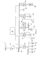
Figure 1 shows one example of amining vehicle 1. Themining vehicle 1 comprises acarriage 2 that may be moved by means of drive equipment 3. The drive equipment 3 comprises one ormore drive motors 4 and one or more power transmission means 5 for transmitting drive power to one ormore wheels 6. The drive power transmission may comprise a mechanical gear system and mechanical power transmission members or, alternatively, a hydraulic or electric drive power system may be used. -
Figure 1 further shows that the mine has aDC trolley line 7. Themining vehicle 1 may be connected to the DCtrolley line 7 with one ormore trolley arms 8. Themining vehicle 1 is provided with electrical switching means 9 providing a connection to allow electricity from the externalDC trolley line 7 to be supplied to different devices of themining vehicle 1. The operation and structure of the electrical switching means 9 is discussed in more detail with reference to the figures below. - The
mining vehicle 1 may be a dumper, loader, rock drilling rig or any other mining vehicle. Themining vehicle 1 may be equipped with one or more mining work devices which mining work device may be one or more of the following mining work devices: rock drilling machine, bolting machine, shotcreting device, scaling device, injection device, blasthole charger, loading device, bucket, box, measuring device, or drilling, sealing and propellant feeding equipment used in small-charge excavation. - As shown in
Figure 2 the mining vehicle is provided with aDC bus 10. In the embodiment shown inFigure 2 the mining vehicle is provided with two drive motors. The drive motor shown withreference numeral 4a is the drive motor for the front wheels. The drive motor shown withreference numeral 4b is the drive motor for the rear wheels. Thedrive motors DC bus 10 byinverters 11. - The mining vehicle may be provided with a
hydraulic pump 12, a motor forair conditioning 13 and one ofmore cooling pumps 14. Thepumps motor 13 are connected to theDC bus 10 by anauxiliary inverter 15. - The
mining vehicle 1 may be provided with a service socket orcharging socket 16. Themining vehicle 1 may also comprise alow voltage system 17. Thelow voltage system 17 supplies energy to the control system and to the lights etc. Thelow voltage system 17 is connected to theDC bus 10 by one or more DC/DC converters 18. Energy may be supplied to thelow voltage system 17 also by abattery 19. - The
mining vehicle 1 may also comprise atraction battery 20. Thetraction battery 20 is connected to theDC bus 10 by a DC/DC converter 21. If for some reason energy cannot be supplied from theexternal trolley line 7 to the mining vehicle it is then possible to supply energy from thetraction battery 20 to move themining vehicle 1. - Each of the
drive motors brake resistors 22. During downhill movement and/or braking thedrive motors brake resistors 22 and/or back to the trolley line. - The operation of the
mining vehicle 1 is controlled by acontrol system 23. -
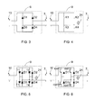
Figure 3 shows an example of the electrical switching means 9. The electrical switching means 9 comprise a diode bridge formed by diodes D1,D2, D3 and D4. - Energy from the external
DC trolley line 7 is supplied to theDC bus 10 of the mining vehicle through the diode bridge. When the polarities are as shown inFigure 3 the diodes D2 and D3 allow current to pass through them. If, however, the mining vehicle is connected to the trolley line such that the polarity is opposite to that shown inFigure 3 , diodes D1 and D4 allow current to pass through them.. Thus in both cases the diode bridge adapts the polarity of the externalDC trolley line 7 to be correct for theDC bus 10 of the mining vehicle. Therefore the need to check the polarity of the trolley line before connecting the mining vehicle to the trolley line may be avoided. - Hence in both cases regarding polarity, the equipment in the mining vehicle is not damaged and energy is supplied to the mining vehicle.
- In the embodiment shown in
Figure 4 the electrical switching means 9 is provided with means for determining the polarity of the externalDC trolley line 7. The means for determining the polarity of the external DC trolley line may be avoltmeter 24, for example. The electrical switching means 9 also comprises contactors K1, K2, K3 and K4. The contactors K1, K2, K3 and K4 are controlled by thecontrol system 23. If the polarity of thetrolley line 7 is determined to be as shown inFigure 4 then thecontrol system 23 controls the contactors such that contactors K2 and K3 are turned on and contactors K1 and K4 are turned off. If the polarity of thetrolley line 7 is determined to be opposite to that shown inFigure 4 then contactors K1 and K4 are turned on and contactors K2 and K3 are turned off. - In the case shown in
Figure 3 as well as in the case shown inFigure 4 the equipment in the mining vehicle is protected. Further, the electrical switching means 9 shown inFigure 4 provide the feature that energy from themining vehicle 1 can be supplied to the externalDC trolley line 7. The need to supply energy from themining vehicle 1 to thetrolley line 7 arises for example from a situation where thedrive motors brake resistors 22 but the energy may be supplied to thetrolley line 7. Therefore in that case thebrake resistors 22 need not be dimensioned to be large. Furthermore supplying energy from themining vehicle 1 to the externalDC trolley line 7 improves the coefficient of efficiency of the system. - In the embodiment shown in
Figure 5 the electrical switching means 9 is provided with the diode bridge as shown inFigure 3 . The electrical switching means 9 further comprises thyristors T1, T2, T3 and T4 connected antiparallel with the diodes D1, D2, D3 and D4 of the diode bridge. Energy from theDC trolley line 7 is supplied to theDC bus 10 through the diode bridge and therefore the polarity in the DC bus of the vehicle is always correct. During regenerative braking, energy may be supplied back to theDC trolley line 7 when the voltage of theDC bus 10 rises above a limit value. Thus, the polarity of theDC trolley line 7 is determined and if the polarity is as shown inFigure 5 thyristors T2 and T3 are turned on and thyristors T1 and T4 are turned off. If the polarity is opposite the thyristors T1 and T4 are turned on and thyristors T2 and T3 are turned off. By using thyristors T1, T2, T3 and T4 instead of contactors K1-K4 a faster control is achieved and a lower current is needed for controlling the electrical switching means. Although a thyristor is more expensive than a contactor, the price is still reasonable. -
Figure 6 shows an embodiment where the structure of the electrical switching means 9 corresponds to that ofFigure 5 with the exception that instead of thyristors T1-T4 transistor switches are used. The transistor switches may be IGBTs (Insulated Gate Bipolar Transistor), for example. The operation of the electrical switching means 9 shown inFigure 6 corresponds to that inFigure 5 . Thus, if the polarity of thetrolley line 7 is as shown inFigure 6 , IGBT2 and IGBT3 are turned on and IGBT1 and IGBT4 are turned off. If the polarity is opposite to that shown inFigure 6 , IGBT1 and IGBT4 are turned on and IGBT2 and IGBT3 are turned off. Also this embodiment provides the feature that the energy from thetrolley line 7 is supplied through the diode bridge D1-D4 to theDC bus 10 whereby the polarity is always correct. Here, too, energy may be supplied back to thetrolley line 7 during regenerative braking when the voltage of theDC bus 10 rises above a limit value. Transistor switches are even faster than thyristors and in addition, they are smaller in size than thyristors. - It will be obvious to a person skilled in the art that, as the technology advances, the inventive concept can be implemented in various ways. The invention and its embodiments are not limited to the examples described above but may vary within the scope of the claims.
Claims (11)
- A mining vehicle, comprising
a carriage,
driving equipment for moving the carriage,
a DC bus for supplying the driving equipment,
means for connecting the DC bus of the mining vehicle to an external DC trolley line, and
an electrical switching means between the DC bus and the external DC trolley line arranged to adapt the polarity of the external DC trolley line to be suitable for the DC bus of the mining vehicle. - A mining vehicle as claimed in claim 1, wherein the electrical switching means comprises means enabling the supply of energy from the vehicle to the external DC trolley line.
- A mining vehicle as claimed in claim 2, wherein the electrical switching means comprises a volt meter arranged to determine the polarity of the external DC trolley line and contactors arranged to be controlled on the basis of the determined polarity of the external DC trolley line.
- A mining vehicle as claimed in claim 2, wherein the electrical switching means comprises a diode bridge adapting the polarity of the external DC trolley line to be suitable for the DC bus of the mining vehicle and thyristors connected antiparallel with the diodes of the diode bridge for enabling the supply of energy from the vehicle to the external DC trolley line.
- A mining vehicle as claimed in claim 2, wherein the electrical switching means comprises a diode bridge adapting the polarity of the external DC trolley line to be suitable for the DC bus of the mining vehicle and transistor switches connected antiparallel with the diodes of the diode bridge for enabling the supply of energy from the vehicle to the external DC trolley line.
- A mining vehicle as claimed in claim 5, wherein the transistor switch is an IGBT.
- A method of connecting a mining vehicle, the mining vehicle comprising
a carriage,
driving equipment for moving the carriage and
a DC bus for supplying the driving equipment,
the method comprising
connecting the DC bus of the mining vehicle to an external DC trolley line, and
adapting the polarity of the external DC trolley line to be suitable for the DC bus of the mining vehicle by an electrical switching means between the DC bus and the external DC trolley line. - A method as claimed in claim 7, comprising supplying energy from the vehicle to the external DC trolley line through said electrical switching means.
- A method as claimed in claim 8, wherein the electrical switching means comprises a voltmeter and contactors, the method comprising determining the polarity of the external DC trolley line by the voltmeter and controlling the contactors on the basis of the determined polarity of the external DC trolley line.
- A method as claimed in claim 8, comprising adapting the polarity of the external DC trolley line to be suitable for the DC bus of the mining vehicle by a diode bridge and supplying energy from the vehicle to the external DC trolley line through thyristors connected antiparallel with the diodes of the diode bridge.
- A method as claimed in claim 8, comprising adapting the polarity of the external DC trolley line to be suitable for the DC bus of the mining vehicle by a diode bridge and supplying energy from the vehicle to the external DC trolley line through transistor switches connected antiparallel with the diodes of the diode bridge.
Priority Applications (1)
| Application Number | Priority Date | Filing Date | Title |
|---|---|---|---|
| EP12170171.8A EP2669110A1 (en) | 2012-05-31 | 2012-05-31 | Mining vehicle |
Applications Claiming Priority (1)
| Application Number | Priority Date | Filing Date | Title |
|---|---|---|---|
| EP12170171.8A EP2669110A1 (en) | 2012-05-31 | 2012-05-31 | Mining vehicle |
Publications (1)
| Publication Number | Publication Date |
|---|---|
| EP2669110A1 true EP2669110A1 (en) | 2013-12-04 |
Family
ID=46397009
Family Applications (1)
| Application Number | Title | Priority Date | Filing Date |
|---|---|---|---|
| EP12170171.8A Withdrawn EP2669110A1 (en) | 2012-05-31 | 2012-05-31 | Mining vehicle |
Country Status (1)
| Country | Link |
|---|---|
| EP (1) | EP2669110A1 (en) |
Cited By (4)
| Publication number | Priority date | Publication date | Assignee | Title |
|---|---|---|---|---|
| DE102015211463B3 (en) * | 2015-06-22 | 2016-09-15 | Siemens Aktiengesellschaft | Energy supply with alternating contact line polarity |
| US9722442B2 (en) | 2014-10-28 | 2017-08-01 | General Electric Company | System and method for transferring energy between vehicles |
| US9718352B2 (en) | 2014-10-28 | 2017-08-01 | General Electric Company | System and method for material transfer and transport |
| EP3741608A1 (en) * | 2019-05-22 | 2020-11-25 | Sandvik Mining and Construction Oy | Mining vehicle |
Citations (5)
| Publication number | Priority date | Publication date | Assignee | Title |
|---|---|---|---|---|
| JPS5597101A (en) | 1979-01-16 | 1980-07-24 | Toshiba Corp | Protecting device for trolley bus |
| DE3150921A1 (en) * | 1981-12-18 | 1983-06-30 | Licentia Patent-Verwaltungs-Gmbh, 6000 Frankfurt | Arrangement for the regenerative braking of railway power units |
| US5221880A (en) * | 1992-10-15 | 1993-06-22 | Balco, Inc. | Underground trolley vehicle with brushless D.C. Motor |
| US5565751A (en) * | 1994-09-28 | 1996-10-15 | Trinity Industries, Inc. | Enhanced traction system for trolleybuses, powered from a 600-volt direct current power line |
| WO2011080392A1 (en) * | 2009-12-28 | 2011-07-07 | Sandvik Mining And Construction Oy | Mining vehicle and method for its energy supply |
-
2012
- 2012-05-31 EP EP12170171.8A patent/EP2669110A1/en not_active Withdrawn
Patent Citations (5)
| Publication number | Priority date | Publication date | Assignee | Title |
|---|---|---|---|---|
| JPS5597101A (en) | 1979-01-16 | 1980-07-24 | Toshiba Corp | Protecting device for trolley bus |
| DE3150921A1 (en) * | 1981-12-18 | 1983-06-30 | Licentia Patent-Verwaltungs-Gmbh, 6000 Frankfurt | Arrangement for the regenerative braking of railway power units |
| US5221880A (en) * | 1992-10-15 | 1993-06-22 | Balco, Inc. | Underground trolley vehicle with brushless D.C. Motor |
| US5565751A (en) * | 1994-09-28 | 1996-10-15 | Trinity Industries, Inc. | Enhanced traction system for trolleybuses, powered from a 600-volt direct current power line |
| WO2011080392A1 (en) * | 2009-12-28 | 2011-07-07 | Sandvik Mining And Construction Oy | Mining vehicle and method for its energy supply |
Cited By (5)
| Publication number | Priority date | Publication date | Assignee | Title |
|---|---|---|---|---|
| US9722442B2 (en) | 2014-10-28 | 2017-08-01 | General Electric Company | System and method for transferring energy between vehicles |
| US9718352B2 (en) | 2014-10-28 | 2017-08-01 | General Electric Company | System and method for material transfer and transport |
| DE102015211463B3 (en) * | 2015-06-22 | 2016-09-15 | Siemens Aktiengesellschaft | Energy supply with alternating contact line polarity |
| EP3741608A1 (en) * | 2019-05-22 | 2020-11-25 | Sandvik Mining and Construction Oy | Mining vehicle |
| WO2020234093A1 (en) * | 2019-05-22 | 2020-11-26 | Sandvik Mining And Construction Oy | Mining vehicle |
Similar Documents
| Publication | Publication Date | Title |
|---|---|---|
| JP6567830B2 (en) | Vehicle propulsion system having a multi-channel DC bus and method of manufacturing the same | |
| KR101144033B1 (en) | Method for controlling motor control system for hybrid vehicle | |
| AU2010347224B2 (en) | Electric drive vehicle, system and method | |
| AU2012346345B2 (en) | Control strategy for providing regenerative electrical power to trolley line in trolley capable mining truck | |
| US8047317B2 (en) | System, vehicle, and method | |
| US9550413B2 (en) | Hybrid work machine | |
| CN104393661A (en) | Starting power generation conversion control method for range extender of electrical vehicle | |
| CA2824622C (en) | Mining vehicle | |
| EP3640066A1 (en) | Propulsion system | |
| NO180436B (en) | Electric drive and distribution system for a vehicle, as well as a method for operating such a system | |
| CN103269927A (en) | Active High Voltage Bus Bleed Down | |
| EP2669110A1 (en) | Mining vehicle | |
| CN104924919A (en) | Apparatus for controlling motor in electric vehicle and method for preventing overheating of traction motor | |
| CN102437814A (en) | Bi-directional back-boost-type inverter device | |
| US9948217B2 (en) | Synchronous energy source switching controller and method of operation thereof | |
| CN204547809U (en) | Electric transmission dumping car power system and electric transmission dumping car | |
| US9481252B1 (en) | Regenerative braking system for reducing fuel consumption | |
| US20160176296A1 (en) | Systems and methods for regenerative dynamic braking | |
| US20220105810A1 (en) | Interface device for a track maintenance machine | |
| KR20110063273A (en) | Method for controlling 12v battery charging voltage of hybrid vehicle | |
| JP6004853B2 (en) | Work machine | |
| US20130140100A1 (en) | Control Strategy For Powering Auxiliary Device In Trolley Capable Mining Truck | |
| JP2008137443A (en) | Working vehicle | |
| CN104810912A (en) | Double-energy double-voltage power supply system | |
| KR20110132958A (en) | Electric terminal prime mover |
Legal Events
| Date | Code | Title | Description |
|---|---|---|---|
| PUAI | Public reference made under article 153(3) epc to a published international application that has entered the european phase |
Free format text: ORIGINAL CODE: 0009012 |
|
| AK | Designated contracting states |
Kind code of ref document: A1 Designated state(s): AL AT BE BG CH CY CZ DE DK EE ES FI FR GB GR HR HU IE IS IT LI LT LU LV MC MK MT NL NO PL PT RO RS SE SI SK SM TR |
|
| AX | Request for extension of the european patent |
Extension state: BA ME |
|
| 17P | Request for examination filed |
Effective date: 20140604 |
|
| RBV | Designated contracting states (corrected) |
Designated state(s): AL AT BE BG CH CY CZ DE DK EE ES FI FR GB GR HR HU IE IS IT LI LT LU LV MC MK MT NL NO PL PT RO RS SE SI SK SM TR |
|
| 17Q | First examination report despatched |
Effective date: 20180111 |
|
| STAA | Information on the status of an ep patent application or granted ep patent |
Free format text: STATUS: THE APPLICATION IS DEEMED TO BE WITHDRAWN |
|
| 18D | Application deemed to be withdrawn |
Effective date: 20190614 |