EP2677224A1 - Clamp connection for pipes - Google Patents
Clamp connection for pipes Download PDFInfo
- Publication number
- EP2677224A1 EP2677224A1 EP12172685.5A EP12172685A EP2677224A1 EP 2677224 A1 EP2677224 A1 EP 2677224A1 EP 12172685 A EP12172685 A EP 12172685A EP 2677224 A1 EP2677224 A1 EP 2677224A1
- Authority
- EP
- European Patent Office
- Prior art keywords
- clamping
- sleeve
- pipe
- clamping sleeve
- connection
- Prior art date
- Legal status (The legal status is an assumption and is not a legal conclusion. Google has not performed a legal analysis and makes no representation as to the accuracy of the status listed.)
- Granted
Links
Images


Classifications
-
- F—MECHANICAL ENGINEERING; LIGHTING; HEATING; WEAPONS; BLASTING
- F16—ENGINEERING ELEMENTS AND UNITS; GENERAL MEASURES FOR PRODUCING AND MAINTAINING EFFECTIVE FUNCTIONING OF MACHINES OR INSTALLATIONS; THERMAL INSULATION IN GENERAL
- F16L—PIPES; JOINTS OR FITTINGS FOR PIPES; SUPPORTS FOR PIPES, CABLES OR PROTECTIVE TUBING; MEANS FOR THERMAL INSULATION IN GENERAL
- F16L33/00—Arrangements for connecting hoses to rigid members; Rigid hose connectors, i.e. single members engaging both hoses
- F16L33/22—Arrangements for connecting hoses to rigid members; Rigid hose connectors, i.e. single members engaging both hoses with means not mentioned in the preceding groups for gripping the hose between inner and outer parts
- F16L33/225—Arrangements for connecting hoses to rigid members; Rigid hose connectors, i.e. single members engaging both hoses with means not mentioned in the preceding groups for gripping the hose between inner and outer parts a sleeve being movable axially
-
- F—MECHANICAL ENGINEERING; LIGHTING; HEATING; WEAPONS; BLASTING
- F16—ENGINEERING ELEMENTS AND UNITS; GENERAL MEASURES FOR PRODUCING AND MAINTAINING EFFECTIVE FUNCTIONING OF MACHINES OR INSTALLATIONS; THERMAL INSULATION IN GENERAL
- F16L—PIPES; JOINTS OR FITTINGS FOR PIPES; SUPPORTS FOR PIPES, CABLES OR PROTECTIVE TUBING; MEANS FOR THERMAL INSULATION IN GENERAL
- F16L37/00—Couplings of the quick-acting type
- F16L37/08—Couplings of the quick-acting type in which the connection between abutting or axially overlapping ends is maintained by locking members
- F16L37/12—Couplings of the quick-acting type in which the connection between abutting or axially overlapping ends is maintained by locking members using hooks, pawls or other movable or insertable locking members
- F16L37/138—Couplings of the quick-acting type in which the connection between abutting or axially overlapping ends is maintained by locking members using hooks, pawls or other movable or insertable locking members using an axially movable sleeve
Definitions
- the invention relates to a clamping connection for pipes made of polymeric material or composites comprising a connecting piece, which has a support sleeve for pushing a pipe to be connected and which is bounded at one end with a stop collar, wherein on the support sleeve, a sealing element is arranged, wherein the clamping connection further comprising a clamping sleeve, which is already connected before the pipe assembly with the stop collar of the connector captive.
- Clamping connections of this type are usually used in the heating and sanitary installation to connect pipes with each other or with fittings.
- a clamp connection By a clamp connection a simple and quick installation is given. Furthermore, a permanent seal is ensured, which is essential in such compounds, since water leakage can cause considerable damage.
- a clamping connection which consists of a clamping sleeve and a fitting body.
- the clamping sleeve has an inner contour which, starting from both sleeve ends, is designed as a conically narrowing or combined conical / convexly narrowing bore as far as the center of the clamping sleeve. This inner contour of the clamping sleeve causes the clamping sleeve, regardless of how it is attached to the pipe is used.
- the DE 195 14 210 C2 also discloses a clamp connection for pipes and hoses of the same type.
- the support and clamping sleeves are designed such that it improves the tightness as well as the longitudinal force fit, which is to be achieved by the ribs on the support sleeve and the inner contour of the clamping sleeve.
- the DE 20 2004 000 031 U1 discloses a pipe press fitting having a support sleeve, a compression sleeve and a ferrule.
- the individual parts are pre-assembled before the pipe installation, so that the assembly work can be reduced to a minimum,
- the assembly itself thereby significantly simplifies the pipe coupling does not have to be first assembled together.
- the connection must not solve in a train on the mounted pipe or the clamping connection should strengthen.
- This object is achieved according to the invention in that the clamping of a tube introduced onto the support sleeve takes place by the displacement of the clamping sleeve via the tube in the opposite direction to the insertion direction of the tube.
- An advantageous embodiment of this clamping connection is that the inner diameter of the connecting piece approximately corresponds to that of the inserted tube or is slightly smaller than the inner diameter of the tube to be inserted.
- the attachment of the novel clamp connection to the pipe or the insertion of the pipe in the clamp connection requires no prior expansion of the pipe by an additional work process to postpone it to the connector, as known from the prior art clamp connections.
- the insertion cone on the connection piece or on the support sleeve allows insertion of the tube without first widening it.
- the insertion cone serves, among other things, the expansion of the tube.
- the stop collar of the connecting piece further serves to prevent the displacement of the clamping sleeve in the mounted state of the clamping connection on one side, or as a one-sided stop for the clamping sleeve. What makes such a connection can not be solved again.
- connection or clamping is reinforced in the event that tension is exerted on the tube. Since the displacement of the clamping sleeve in the direction of the sealing element, by the train on the tube, the clamping between the sealing element or support sleeve and tapered inner diameter of the clamping sleeve still reinforced.
- the clamping sleeve preferably has two areas. One of them is elastic and serves for pre-assembly, as well as the assembly of the clamp connection. The second area is rigid and serves the clamping, as well as the leadership of the tube. Of course, the clamping sleeve may have further areas.
- the inner diameter of the clamping of the tube is achieved in cooperation with the sealing element or the Quer4.000erweit réelle the support sleeve.
- the taper occurs in the rigid area of the clamping sleeve in Direction of the elastic area.
- the dimension of the inner diameter of the elastic region is independent of the course of the inner diameter or the inner contour of the rigid region, preferably the inner diameter in the elastic region is greater than the outer diameter of the inserted tube and does not affect the tube in the assembled state of the clamping connection.
- the elastic region is formed by at least two segments, which are preferably distributed regularly over the circumference.
- the elastic region has eight to 16 segments, which ensure the radial elasticity.
- the clamping sleeve serves a groove along the inner diameter of the segments.
- the clamping sleeve is fixed to the stop collar and positioned or preassembled.
- the groove corresponds to the width of the stop collar.
- the clamping sleeve in the groove and the stop collar have a corresponding phase or slope, which simplify the assembly and the pushing down of the clamping sleeve from the stop collar.
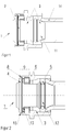
- Fig. 1 shows a clamping connection 1 according to the invention, in which the pipe 14 to be connected is already pushed lightly onto the conical region of the support sleeve 3 or the insertion cone 11.
- the connecting piece 2 has an insertion cone 11, which allows the insertion of the pipe 14 to be connected.
- cone 11 can be dispensed with a prior widening of the tube 14, which saves a step in the assembly and makes the assembly easier and faster.
- the pre-assembled on the connector 2 clamping sleeve 6 is used, inter alia, the guiding of the tube 14 during insertion, what Fig. 2 is apparent.
- the tube 14 Upon reaching the clamping sleeve 6, the tube 14 is guided along the inner contour or the inner diameter of the clamping sleeve 6 and along the support sleeve 3.
- the sealing element 5, which is preferably formed by an O-ring, serves for optimal tightness of the clamping connection 1.
- the sealing element 5 is arranged on the support sleeve 3 and is located in a groove 12 provided for this, which prevents the displacement of the sealing element 5.
- the tube 14 is pushed up to the radius 13 in the clamping connection 1 and then fastened with the already pre-assembled on the connector 2 clamping sleeve 6.
- the clamping sleeve 6, as already mentioned, is preassembled on the connecting piece 2.
- the connecting piece 2 has at the opposite end of the insertion cone 11 of the support sleeve 3 a stop 4. Among other things, it serves to pre-assemble the clamping sleeve 6.
- the clamping sleeve 6 is fastened to the stop collar 4.
- the radially elastic portion 9 of the clamping sleeve 6 the pre-assembly and the removal of the clamping sleeve 6 is ensured by the stop collar 4. Due to the arrangement of segments 7 on the clamping sleeve 6, which in Fig. 7 are visible, a radially elastic region 9 is formed on the clamping sleeve 6.
- the segments 7 can be easily widened in the radial direction to introduce the stop collar 4 of the connector 2. Due to their elasticity they then clamp firmly to the stop collar 4, the inner contour of the segments 7 having a groove 8, which corresponds to the width of the stop collar 4, whereby the clamping sleeve 6 is fixed or positioned axially on the stop collar 4.
- the elastic region 9 consists of at least two segments 7. It is advantageous if both the clamping sleeve 6 as well as the stop collar 4 have a phase 15 which facilitate the pushing down of the clamping sleeve 6 from the stop collar 4 on the inserted tube 14.
- Fig. 3 illustrates this process.
- the support sleeve 3 at this point has an enlarged cross-section, which causes a clamping action during displacement of the clamping sleeve 6 in the direction of sealing element 5 ,
- Fig. 4 the finished assembled clamp connection 1 is shown.
- the clamping would be reinforced by pulling on the tube 14, since the clamping sleeve 6 would also move in the same direction and thus would be present on the sealing element 5 due to the tapered diameter of the clamping sleeve 6 or the tube 14 located therebetween accordingly would be squeezed.
- the stop collar 4 is used after assembly to the fact that the clamping sleeve 6 is limited in the other direction and is not removable.
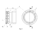
- Fig. 5 shows a pipe coupling 16, which is suitable for connecting pipes 14.
- the coupling 16 has on both sides a clamping connection 1 according to the invention.
- the pipe coupling 16 is shown in the preassembled state.
- Such clamp connections 1 are, for example, also for connections to valves.
- Fig. 6 an inventive clamp connection 1 is shown, which is arranged on a distributor.
- the radially elastic region 9 is composed of segments 7 which are arranged along the circumference. The number and size of the segments 7 are adapted to the requirements of the clamp connection 1 and to its dimension.
- the inner contour or the inner diameter in the rigid region 10 tapers in the direction of the elastic region 9, as a result of which, as described above, the clamping effect is achieved as a function of the support sleeve 3.
Abstract
Description
Die Erfindung betrifft eine Klemmverbindung für Rohre aus polymerem Werkstoff oder aus Verbundwerkstoffen beinhaltend ein Anschlussstück, welches eine Stützhülse für das Aufschieben eines anzuschliessenden Rohres aufweist und die an einem Ende mit einem Anschlagbund begrenzt ist, wobei an der Stützhülse ein Dichtelement angeordnet ist, wobei die Klemmverbindung weiter eine Klemmhülse aufweist, welche bereits vor der Rohrmontage mit dem Anschlagbund des Anschlussstücks unverlierbar verbunden ist.The invention relates to a clamping connection for pipes made of polymeric material or composites comprising a connecting piece, which has a support sleeve for pushing a pipe to be connected and which is bounded at one end with a stop collar, wherein on the support sleeve, a sealing element is arranged, wherein the clamping connection further comprising a clamping sleeve, which is already connected before the pipe assembly with the stop collar of the connector captive.
Rohre aus polymerem Werkstoff wie beispielsweise PE-X Rohre und Mehrschichtverbundrohre, die beispielsweise eine Innen- und Aussenschicht aus einem polymeren Werkstoff wie PE-X und eine Zwischenschicht aus Aluminium aufweisen werden überwiegend in der Haustechnik, in der Trinkwasserversorgung, für Fussbodenheizungen oder Heizkörperanschlussleitungen eingesetzt.Tubes made of polymeric material such as PE-X pipes and multi-layer composite pipes, for example, have an inner and outer layer of a polymeric material such as PE-X and an intermediate layer of aluminum are mainly used in building services, in the drinking water supply, for underfloor heating or radiator connection lines.
Klemmverbindungen dieser Art werden meist in der Heizungs- und Sanitärinstallation eingesetzt um Rohre untereinander oder mit Armaturen zu verbinden. Durch eine Klemmverbindung ist eine einfache und schnelle Montage gegeben. Des Weiteren ist eine dauerhafte Abdichtung gewährleistet, was wesentlich bei solchen Verbindungen ist, da bei Wasseraustritt erhebliche Schäden entstehen können.Clamping connections of this type are usually used in the heating and sanitary installation to connect pipes with each other or with fittings. By a clamp connection a simple and quick installation is given. Furthermore, a permanent seal is ensured, which is essential in such compounds, since water leakage can cause considerable damage.
Aus der
Nachteilig daran sind die Herstellung der komplexen Innenkontur der Klemmhülse sowie die anschliessende Kontrolle der Kontur.The disadvantage of this is the production of the complex inner contour of the clamping sleeve and the subsequent control of the contour.
Die
Bei beiden zuvor erwähnten Klemmverbindungen besteht der Nachteil, dass das anzuschiessende Rohr vor dem Verbinden zuerst Aufgeweitet werden muss um es anschliessend über die Stützhülse schieben zu können. Das bedingt eines zusätzlichen Arbeitsschrittes was die Montage aufwendiger macht. Zudem kann das Aufschieben der Klemmhülse bei den zuvor erwähnten Verbindungen vor dem Anbringen des Rohres an der Stützhülse leicht vergessen gehen, weshalb das Rohr dann wieder von der Stützhülse zu entfernen ist und die Klemmhülse nachträglich auf das Rohr aufgesteckt werden muss. Das Rohr kann dann von neuem auf die Stützhülse geschoben werden.In the case of both clamping connections mentioned above, there is the disadvantage that the pipe to be connected first has to be widened before being connected, in order then to be able to push it over the supporting sleeve. This requires an additional step which makes the assembly more complex. In addition, the sliding of the clamping sleeve in the aforementioned compounds before attaching the tube to the support sleeve easily go forgotten, which is why the tube is then removed again from the support sleeve and the clamping sleeve must be subsequently attached to the pipe. The tube can then be pushed onto the support sleeve again.
Die
Nachteilig an dieser Kupplung ist jedoch die starke Querschnittverengung im Hinblick auf den Rohrquerschnitt. Zudem weist auch diese Art der Rohrverbindung wie die zuvor erwähnten Verbindungen den Nachteil auf, dass bei starkem Zug auf das Rohr sich die Klemmung/Pressung bzw. Klemmhülse/Presshülse löst.A disadvantage of this coupling, however, is the strong cross-sectional constriction in terms of the pipe cross-section. In addition, this type of pipe connection as the compounds mentioned above has the disadvantage that in strong train on the pipe, the clamping / compression or clamping sleeve / compression sleeve dissolves.
Es ist Aufgabe der Erfindung, eine Klemmverbindung vorzuschlagen, welche einfach zu montieren und günstig in der Herstellung ist. Zudem darf sich die Verbindung bei einem Zug auf das montierte Rohr nicht lösen bzw. die Klemmverbindung sollte sich verstärken.It is an object of the invention to provide a clamping connection, which is easy to assemble and low in production. In addition, the connection must not solve in a train on the mounted pipe or the clamping connection should strengthen.
Diese Aufgabe wird erfindungsgemäss dadurch gelöst, dass die Klemmung eines auf die Stützhülse eingeführten Rohres durch die Verschiebung der Klemmhülse über das Rohr in entgegengesetzter Richtung zur Einführrichtung des Rohres erfolgt. Eine Vorteilhafte Ausgestaltung dieser Klemmverbindung liegt darin, dass der Innendurchmesser des Anschlussstücks dem des einzuführenden Rohres annähernd entspricht bzw. geringfügig kleiner ist als der Innendurchmesser des einzuführenden Rohres. Dadurch können Querschnittsverengungen in der Leitung bzw. beim Anschluss an Armaturen mittels der erfindungsgemässen Klemmverbindung gering gehalten werden, was strömungstechnisch positiv ist.This object is achieved according to the invention in that the clamping of a tube introduced onto the support sleeve takes place by the displacement of the clamping sleeve via the tube in the opposite direction to the insertion direction of the tube. An advantageous embodiment of this clamping connection is that the inner diameter of the connecting piece approximately corresponds to that of the inserted tube or is slightly smaller than the inner diameter of the tube to be inserted. As a result, cross-sectional constrictions in the line or when connecting to valves by means of the inventive clamping connection can be kept low, which is aerodynamically positive.
Das Anbringen der erfindungsgemässen Klemmverbindung an der Rohrleitung bzw. das Einführen des Rohres in die Klemmverbindung benötigt kein vorausgehendes Aufweiten des Rohres durch einen zusätzlichen Arbeitsprozess um es danach auf das Anschlussstück aufzuschieben, wie aus den Klemmverbindungen aus dem Stand der Technik bekannt. Der Einführkonus am Anschlussstück bzw. an der Stützhülse ermöglicht das Einführen des Rohres ohne es zuvor aufzuweiten. Der Einführkonus dient unteranderem dem Aufweiten des Rohres.The attachment of the novel clamp connection to the pipe or the insertion of the pipe in the clamp connection requires no prior expansion of the pipe by an additional work process to postpone it to the connector, as known from the prior art clamp connections. The insertion cone on the connection piece or on the support sleeve allows insertion of the tube without first widening it. The insertion cone serves, among other things, the expansion of the tube.
Der Anschlagbund des Anschlussstücks dient des Weiteren dazu, das Verschieben der Klemmhülse im montierten Zustand der Klemmverbindung einseitig zu verhindern, bzw. als einseitigen Anschlag für die Klemmhülse. Wodurch eine solche Verbindung auch nicht wieder lösbar ist.The stop collar of the connecting piece further serves to prevent the displacement of the clamping sleeve in the mounted state of the clamping connection on one side, or as a one-sided stop for the clamping sleeve. What makes such a connection can not be solved again.
Durch die erfindungsgemässe Klemmverbindung wird zudem erreicht, dass sich die Verbindung bzw. Klemmung verstärkt, im Falle dass Zug auf das Rohr ausgeübt wird. Da das Verschieben der Klemmhülse in Richtung Dichtelement, durch den Zug auf das Rohr, die Klemmung zwischen Dichtelement bzw. Stützhülse und verjüngtem Innendurchmesser der Klemmhülse noch verstärkt.By means of the clamping connection according to the invention it is also achieved that the connection or clamping is reinforced in the event that tension is exerted on the tube. Since the displacement of the clamping sleeve in the direction of the sealing element, by the train on the tube, the clamping between the sealing element or support sleeve and tapered inner diameter of the clamping sleeve still reinforced.
Die Klemmhülse weist vorzugsweise zwei Bereiche auf. Davon ist einer elastisch und dient der Vormontage, sowie der Montage der Klemmverbindung. Der zweite Bereich ist starr und dient der Klemmung, sowie der Führung des Rohres. Selbstverständlich kann die Klemmhülse noch weitere Bereiche aufweisen.The clamping sleeve preferably has two areas. One of them is elastic and serves for pre-assembly, as well as the assembly of the clamp connection. The second area is rigid and serves the clamping, as well as the leadership of the tube. Of course, the clamping sleeve may have further areas.
Durch die Verjüngung des Innendurchmessers wird die Klemmung des Rohres im Zusammenspiel mit dem Dichtelement bzw. der Querschnitterweiterung der Stützhülse erzielt. Die Verjüngung erfolgt im starren Bereich der Klemmhülse in Richtung des elastischen Bereichs. Wobei die Dimension des Innendurchmessers des elastischer Bereichs unabhängig vom Verlauf des Innendurchmessers bzw. der Innenkontur des starren Bereichs ist, vorzugsweise ist der Innendurchmesser im elastischen Bereich grösser als der Aussendurchmesser des eingeführten Rohres und tangiert das Rohr auch nicht im montiertem Zustand der Klemmverbindung.By tapering the inner diameter of the clamping of the tube is achieved in cooperation with the sealing element or the Querschnitterweiterung the support sleeve. The taper occurs in the rigid area of the clamping sleeve in Direction of the elastic area. Wherein the dimension of the inner diameter of the elastic region is independent of the course of the inner diameter or the inner contour of the rigid region, preferably the inner diameter in the elastic region is greater than the outer diameter of the inserted tube and does not affect the tube in the assembled state of the clamping connection.
Der elastische Bereich wird durch mindestens zwei Segmente gebildet, welche vorzugsweise regelmässig über den Umfang verteilt sind. Vorzugsweise weist der elastische Bereich acht bis 16 Segmente auf, die die radiale Elastizität gewährleisten.The elastic region is formed by at least two segments, which are preferably distributed regularly over the circumference. Preferably, the elastic region has eight to 16 segments, which ensure the radial elasticity.
Zur axialen Positionierung, sowie Fixierung der Klemmhülse dient eine Rille entlang des Innendurchmessers der Segmente. Dadurch wird die Klemmhülse am Anschlagbund fixiert und positioniert bzw. vormontiert. Die Rille entspricht der Breite des Anschlagbunds. Eine vorteilhafte Ausführung besteht darin, dass die Klemmhülse in der Rille sowie der Anschlagbund eine korrespondierende Phase bzw. Schräge aufweisen, die die Montage bzw. das Hinunterschieben der Klemmhülse vom Anschlagbund vereinfachen.For axial positioning, as well as fixing the clamping sleeve serves a groove along the inner diameter of the segments. As a result, the clamping sleeve is fixed to the stop collar and positioned or preassembled. The groove corresponds to the width of the stop collar. An advantageous embodiment is that the clamping sleeve in the groove and the stop collar have a corresponding phase or slope, which simplify the assembly and the pushing down of the clamping sleeve from the stop collar.
Ein Ausführungsbeispiel der Erfindung wird anhand der Figuren beschrieben, wobei sich die Erfindung nicht nur auf das Ausführungsbeispiel beschränkt. Es zeigen:
- Fig. 1
- einen Längschnitt durch eine erfindungsgemässe vormontierte Klemmverbindung bei anfänglicher Rohrmontage,
- Fig. 2
- einen Längschnitt durch eine erfindungsgemässe vormontierte Klemmverbindung bei wenig fortgeschrittener Rohrmontage
- Fig. 3
- einen Längschnitt durch eine erfindungsgemässe vormontierte Klemmverbindung bei komplett eingeführtem Rohr,
- Fig. 4
- einen Längschnitt durch eine erfindungsgemässe vormontierte Klemmverbindung in fertig montiertem Zustand,
- Fig. 5
- einen Längschnitt durch eine vormontierte Rohrkupplung, die beidseitig eine erfindungsgemässe Klemmverbindung aufweist,
- Fig. 6
- eine Ansicht eines Verteilers, welcher erfindungsgemässe Klemmverbindungen zum anschliessen der Rohre aufweist und
- Fig. 7
- einen Längschnitt und eine Ansicht der Klemmhülse der erfindungsgemässe Klemmverbindung.
- Fig. 1
- a longitudinal section through a preassembled clamping connection according to the invention during initial pipe installation,
- Fig. 2
- a longitudinal section through an inventive preassembled clamp connection with little advanced pipe installation
- Fig. 3
- a longitudinal section through an inventive preassembled clamp connection with completely inserted pipe,
- Fig. 4
- a longitudinal section through a preassembled clamping connection according to the invention in the fully assembled state,
- Fig. 5
- a longitudinal section through a preassembled pipe coupling, which has on both sides a clamping connection according to the invention,
- Fig. 6
- a view of a distributor, which inventive clamping connections for connecting the pipes and has
- Fig. 7
- a longitudinal section and a view of the clamping sleeve of the inventive clamp connection.
In
Aus dem Stand der Technik ist keine solche Klemmverbindung bekannt, bei welcher das Aufschieben der Klemmhülse entgegen der Einführungsrichtung des Rohres erfolgt, da ein solcher Vorgang bisher als unlogisch empfunden wurde, da dadurch das Rohr bei den bekannten Klemmverbindungen wieder von der Stützhülse hinuntergeschoben werden würde. Zudem ist die Klemmhülse bei herkömmlichen Klemmverbindungen, welche vormontiert sind ebenfalls an der Stützhülse angebracht jedoch nicht auf der Seite des Anschlagbunds sondern auch auf der Seite des einzuführenden Rohres.From the prior art, no such clamping connection is known, in which the sliding of the clamping sleeve against the direction of insertion of the tube takes place, since such a process was previously considered illogical, since thereby the tube would be pushed down again in the known clamping connections of the support sleeve. In addition, the clamping sleeve in conventional clamping connections, which are also pre-mounted on the support sleeve but not on the side of the stop collar but also on the side of the pipe to be inserted.
Durch den Verlauf der Innenkontur bzw. der Verjüngung des Innendurchmessers der Klemmhülse 6 der vorliegenden Erfindung und die Querschnittserweiterung der Stützhülse 3 durch das Dichtelement 5 ist eine Montage in diese Richtung des Rohres 14 möglich, wobei eine blosse Querschnittserweiterung an der Stützhülse 3 ohne Dichtelement 5 ebenso denkbar ist um dies Klemmwirkung zu erreichen, bei welcher sich die Klemmung bei Zug auf das Rohr verstärkt anstatt löst. Aus
Die Rohrkupplung 16 ist im vormontierten Zustand dargestellt. Solche Klemmverbindungen 1 eignen sich bspw. auch für Anschlüsse an Armaturen.The
In
Die Klemmhülse 6 der erfindungsgemässen Klemmverbindung 1, welche in
- 11
- Klemmverbindungclamp connection
- 22
- Anschlussstückconnector
- 33
- Stützhülsesupport sleeve
- 44
- Anschlagbundstop collar
- 55
- Dichtelementsealing element
- 66
- Klemmhülsecollet
- 77
- Segmentsegment
- 88th
- Rillegroove
- 99
- elastischer Bereichelastic range
- 1010
- starrer Bereichrigid area
- 1111
- Einführkonusintroduction cone
- 1212
- Nutgroove
- 1313
- Radiusradius
- 1414
- Rohrpipe
- 1515
- Phasephase
- 1616
- Rohrkupplungpipe coupling
- 1717
- Stegweb
Claims (10)
Priority Applications (15)
| Application Number | Priority Date | Filing Date | Title |
|---|---|---|---|
| EP12172685.5A EP2677224B1 (en) | 2012-06-20 | 2012-06-20 | Clamp connection for pipes |
| PL12172685.5T PL2677224T3 (en) | 2012-06-20 | 2012-06-20 | Clamp connection for pipes |
| PT121726855T PT2677224T (en) | 2012-06-20 | 2012-06-20 | Clamp connection for pipes |
| HUE12172685A HUE029286T2 (en) | 2012-06-20 | 2012-06-20 | Clamp connection for pipes |
| TW102118669A TWI570346B (en) | 2012-06-20 | 2013-05-27 | Clamping joint for pipes |
| US14/409,334 US9599264B2 (en) | 2012-06-20 | 2013-06-05 | Clamping joint for pipes |
| JP2015517661A JP6223441B2 (en) | 2012-06-20 | 2013-06-05 | Clamp connection for pipe |
| PCT/EP2013/061574 WO2013189740A2 (en) | 2012-06-20 | 2013-06-05 | Clamping connection for pipes |
| RU2015101576A RU2622341C2 (en) | 2012-06-20 | 2013-06-05 | Clamping pipe joint |
| AU2013279656A AU2013279656B2 (en) | 2012-06-20 | 2013-06-05 | Clamping connection for pipes |
| KR1020147035747A KR102120503B1 (en) | 2012-06-20 | 2013-06-05 | Clamping connection for pipes |
| CN201380032251.1A CN104395665B (en) | 2012-06-20 | 2013-06-05 | Clamp connection for pipeline |
| SG11201407648TA SG11201407648TA (en) | 2012-06-20 | 2013-06-05 | Clamping connection for pipes |
| CA2873513A CA2873513C (en) | 2012-06-20 | 2013-06-05 | Clamping connection for pipes |
| HK14105944.0A HK1192773A1 (en) | 2012-06-20 | 2014-06-23 | Clamp connection for pipes |
Applications Claiming Priority (1)
| Application Number | Priority Date | Filing Date | Title |
|---|---|---|---|
| EP12172685.5A EP2677224B1 (en) | 2012-06-20 | 2012-06-20 | Clamp connection for pipes |
Publications (2)
| Publication Number | Publication Date |
|---|---|
| EP2677224A1 true EP2677224A1 (en) | 2013-12-25 |
| EP2677224B1 EP2677224B1 (en) | 2016-05-25 |
Family
ID=49510110
Family Applications (1)
| Application Number | Title | Priority Date | Filing Date |
|---|---|---|---|
| EP12172685.5A Active EP2677224B1 (en) | 2012-06-20 | 2012-06-20 | Clamp connection for pipes |
Country Status (15)
| Country | Link |
|---|---|
| US (1) | US9599264B2 (en) |
| EP (1) | EP2677224B1 (en) |
| JP (1) | JP6223441B2 (en) |
| KR (1) | KR102120503B1 (en) |
| CN (1) | CN104395665B (en) |
| AU (1) | AU2013279656B2 (en) |
| CA (1) | CA2873513C (en) |
| HK (1) | HK1192773A1 (en) |
| HU (1) | HUE029286T2 (en) |
| PL (1) | PL2677224T3 (en) |
| PT (1) | PT2677224T (en) |
| RU (1) | RU2622341C2 (en) |
| SG (1) | SG11201407648TA (en) |
| TW (1) | TWI570346B (en) |
| WO (1) | WO2013189740A2 (en) |
Cited By (1)
| Publication number | Priority date | Publication date | Assignee | Title |
|---|---|---|---|---|
| EP3130831A1 (en) * | 2014-05-26 | 2017-02-15 | Bridgestone Corporation | Pipe joint |
Families Citing this family (18)
| Publication number | Priority date | Publication date | Assignee | Title |
|---|---|---|---|---|
| FR3023349B1 (en) * | 2014-07-04 | 2017-02-10 | Sartorius Stedim Fmt Sas | FLUIDIC CONNECTOR WITH CRIMPING COLLAR PRE-POSITIONED. |
| JP2016161032A (en) * | 2015-03-02 | 2016-09-05 | タイガースポリマー株式会社 | Connector member for pipe passage block connection and its manufacturing method |
| JP6468678B2 (en) * | 2015-04-02 | 2019-02-13 | 光陽産業株式会社 | Medical connection structure |
| DE102015209821B4 (en) | 2015-05-28 | 2022-08-25 | Novopress Gmbh Pressen Und Presswerkzeuge & Co. Kg | Connection device and method for pressing a pipe end with a sliding fitting by axial displacement, as well as pressing device and use of a pressing device for actuating such a connection device |
| CN105020514B (en) * | 2015-06-19 | 2019-04-12 | 包金平 | Seal nipple inside and outside fast ski-running tightly |
| US11441713B2 (en) | 2015-10-06 | 2022-09-13 | Global Life Sciences Solutions Usa Llc | Connection clamping device |
| US11541581B2 (en) | 2016-09-02 | 2023-01-03 | Zurn Industries, Llc | Injection molded cold-expansion compression collar |
| US11543065B2 (en) | 2016-09-02 | 2023-01-03 | Zurn Industries, Llc | Extruded cold-expansion compression collar |
| EP3312027B1 (en) * | 2016-10-19 | 2019-08-28 | The Goodyear Tire & Rubber Company | Connection assembly for an air maintenance tire system and air maintenance tire system |
| US11054076B2 (en) | 2016-11-04 | 2021-07-06 | Zurn Industries, Llc | Reinforcing ring with sleeve |
| EP3379129B1 (en) | 2017-03-23 | 2022-09-28 | Georg Fischer JRG AG | Connector |
| EP3607233B1 (en) | 2017-04-05 | 2024-03-13 | Global Life Sciences Solutions USA LLC | Connection clamping device |
| USD854657S1 (en) | 2017-04-11 | 2019-07-23 | Georg Fischer Jrg Ag | Control valve |
| GB201710279D0 (en) | 2017-06-28 | 2017-08-09 | Ge Healthcare Bio Sciences Ab | Improvements in and relating to bioprocessing equipment and fluid couplings therefor |
| CN107401647A (en) * | 2017-08-15 | 2017-11-28 | 日丰企业(佛山)有限公司 | Pipe fitting connecting method and attachment structure |
| KR102352930B1 (en) * | 2017-12-20 | 2022-01-20 | 생-고뱅 퍼포먼스 플라스틱스 코포레이션 | Double Containment Fittings and Double Containment Fittings Assemblies |
| CN111174012B (en) * | 2020-03-14 | 2021-07-30 | 绍兴上虞中塘电器五金厂 | Detachable pipe plug |
| US20230304717A1 (en) * | 2022-03-22 | 2023-09-28 | Whirlpool Corporation | Water fill tube with thermally conductive filled polymer |
Citations (7)
| Publication number | Priority date | Publication date | Assignee | Title |
|---|---|---|---|---|
| DE4239705C2 (en) | 1992-11-26 | 1993-12-16 | Hennig Christoph Dipl Kaufm | Sliding sleeve and clamp connector for connecting pipes and hoses made of polymer materials |
| DE19514210C2 (en) | 1995-04-15 | 1997-11-27 | Ivt Installations Und Verbindu | Clamp connector |
| US20020000721A1 (en) * | 2000-06-08 | 2002-01-03 | Hitachi Metals, Ltd. | Sleeve-type pipe joint |
| US6641177B1 (en) * | 2000-08-25 | 2003-11-04 | Precision Design Concepts, Llc | Quick connect tube coupling and method of assembling the same |
| DE202004000031U1 (en) | 2004-01-02 | 2004-07-01 | Reckzeh, Manfred | Pipe coupling comprises crimping sleeve and press fitting, support sleeve fitting inside pipe which is attached to either crimping sleeve or both crimping sleeve and press fitting before it is positioned in pipe |
| EP1598903A2 (en) * | 2004-05-14 | 2005-11-23 | Thomas & Betts International, Inc. | Coaxial cable connector |
| EP1835220A1 (en) * | 2006-03-14 | 2007-09-19 | NORMA Germany GmbH | Connector assembly for connecting a pipe socket with a hose |
Family Cites Families (17)
| Publication number | Priority date | Publication date | Assignee | Title |
|---|---|---|---|---|
| DE2260734C3 (en) * | 1972-12-12 | 1984-09-20 | Georg Dr.-Ing. 8152 Feldkirchen-Westerham Spinner | RF coaxial connector |
| JPS6296191U (en) * | 1985-12-07 | 1987-06-19 | ||
| US4923226A (en) * | 1987-06-23 | 1990-05-08 | Proprietary Technology, Inc. | Apparatus for attaching a hose to a fitting |
| US4903995A (en) * | 1988-09-30 | 1990-02-27 | Colder Products Company | Self-tightening soft tubing fitting and method of use |
| JPH0633278Y2 (en) * | 1989-03-06 | 1994-08-31 | ニッタ・ムアー株式会社 | Sleeve for pipe fittings |
| JPH0377893U (en) * | 1989-10-04 | 1991-08-06 | ||
| JPH03127888U (en) * | 1990-04-05 | 1991-12-24 | ||
| FI102635B (en) * | 1997-03-18 | 1999-01-15 | Uponor Innovation Ab | Process for making a pipe connection and a pipe connection |
| JP3405966B2 (en) * | 2000-02-07 | 2003-05-12 | 東尾メック株式会社 | Pipe fitting |
| DE60134826D1 (en) * | 2000-05-10 | 2008-08-28 | Thomas & Betts Int | COAXIAL BRAKE WITH A REMOVABLE LOCKING RING |
| US6796586B2 (en) * | 2001-07-09 | 2004-09-28 | Twin Bay Medical, Inc. | Barb clamp |
| WO2003046429A1 (en) * | 2001-11-28 | 2003-06-05 | Friatec Aktiengesellschaft | Plug-in connector |
| DE102004052475A1 (en) * | 2004-10-28 | 2006-05-04 | Eaton Fluid Power Gmbh | Pull-resistant plug-in coupling |
| DE102008039446B4 (en) * | 2008-07-07 | 2015-12-17 | Viega Gmbh & Co. Kg | Arrangement and method for producing a non-detachable workpiece connection |
| AT508668B1 (en) * | 2010-02-10 | 2011-03-15 | Ke Kelit Kunststoffwerk Gmbh | CONNECTION DEVICE FOR A SUSPENDED TUBE |
| JP5661430B2 (en) * | 2010-11-16 | 2015-01-28 | 株式会社ブリヂストン | Pipe fitting |
| CN102121547B (en) * | 2010-12-23 | 2013-01-16 | 拉卡萨安吉拉股份有限公司 | Bushing for pipe joint and pipe joint adopting bushing |
-
2012
- 2012-06-20 PT PT121726855T patent/PT2677224T/en unknown
- 2012-06-20 PL PL12172685.5T patent/PL2677224T3/en unknown
- 2012-06-20 EP EP12172685.5A patent/EP2677224B1/en active Active
- 2012-06-20 HU HUE12172685A patent/HUE029286T2/en unknown
-
2013
- 2013-05-27 TW TW102118669A patent/TWI570346B/en active
- 2013-06-05 KR KR1020147035747A patent/KR102120503B1/en active IP Right Grant
- 2013-06-05 RU RU2015101576A patent/RU2622341C2/en active
- 2013-06-05 SG SG11201407648TA patent/SG11201407648TA/en unknown
- 2013-06-05 JP JP2015517661A patent/JP6223441B2/en active Active
- 2013-06-05 AU AU2013279656A patent/AU2013279656B2/en active Active
- 2013-06-05 WO PCT/EP2013/061574 patent/WO2013189740A2/en active Application Filing
- 2013-06-05 CN CN201380032251.1A patent/CN104395665B/en active Active
- 2013-06-05 US US14/409,334 patent/US9599264B2/en active Active
- 2013-06-05 CA CA2873513A patent/CA2873513C/en active Active
-
2014
- 2014-06-23 HK HK14105944.0A patent/HK1192773A1/en unknown
Patent Citations (7)
| Publication number | Priority date | Publication date | Assignee | Title |
|---|---|---|---|---|
| DE4239705C2 (en) | 1992-11-26 | 1993-12-16 | Hennig Christoph Dipl Kaufm | Sliding sleeve and clamp connector for connecting pipes and hoses made of polymer materials |
| DE19514210C2 (en) | 1995-04-15 | 1997-11-27 | Ivt Installations Und Verbindu | Clamp connector |
| US20020000721A1 (en) * | 2000-06-08 | 2002-01-03 | Hitachi Metals, Ltd. | Sleeve-type pipe joint |
| US6641177B1 (en) * | 2000-08-25 | 2003-11-04 | Precision Design Concepts, Llc | Quick connect tube coupling and method of assembling the same |
| DE202004000031U1 (en) | 2004-01-02 | 2004-07-01 | Reckzeh, Manfred | Pipe coupling comprises crimping sleeve and press fitting, support sleeve fitting inside pipe which is attached to either crimping sleeve or both crimping sleeve and press fitting before it is positioned in pipe |
| EP1598903A2 (en) * | 2004-05-14 | 2005-11-23 | Thomas & Betts International, Inc. | Coaxial cable connector |
| EP1835220A1 (en) * | 2006-03-14 | 2007-09-19 | NORMA Germany GmbH | Connector assembly for connecting a pipe socket with a hose |
Cited By (3)
| Publication number | Priority date | Publication date | Assignee | Title |
|---|---|---|---|---|
| EP3130831A1 (en) * | 2014-05-26 | 2017-02-15 | Bridgestone Corporation | Pipe joint |
| EP3130831A4 (en) * | 2014-05-26 | 2017-04-26 | Bridgestone Corporation | Pipe joint |
| TWI645128B (en) * | 2014-05-26 | 2018-12-21 | 日商普利司通股份有限公司 | Pipe joint |
Also Published As
| Publication number | Publication date |
|---|---|
| RU2622341C2 (en) | 2017-06-14 |
| TW201411018A (en) | 2014-03-16 |
| EP2677224B1 (en) | 2016-05-25 |
| HUE029286T2 (en) | 2017-02-28 |
| US20150167874A1 (en) | 2015-06-18 |
| CA2873513C (en) | 2019-07-09 |
| AU2013279656B2 (en) | 2016-04-28 |
| WO2013189740A2 (en) | 2013-12-27 |
| PT2677224T (en) | 2016-07-15 |
| CA2873513A1 (en) | 2013-12-27 |
| AU2013279656A1 (en) | 2014-12-18 |
| WO2013189740A3 (en) | 2014-06-19 |
| JP2015524041A (en) | 2015-08-20 |
| SG11201407648TA (en) | 2015-01-29 |
| CN104395665A (en) | 2015-03-04 |
| HK1192773A1 (en) | 2014-08-29 |
| KR20150027106A (en) | 2015-03-11 |
| TWI570346B (en) | 2017-02-11 |
| CN104395665B (en) | 2016-12-07 |
| RU2015101576A (en) | 2016-08-10 |
| PL2677224T3 (en) | 2016-12-30 |
| KR102120503B1 (en) | 2020-06-09 |
| JP6223441B2 (en) | 2017-11-01 |
| US9599264B2 (en) | 2017-03-21 |
Similar Documents
| Publication | Publication Date | Title |
|---|---|---|
| EP2677224B1 (en) | Clamp connection for pipes | |
| DE2629905C3 (en) | ||
| DE202005008109U1 (en) | Press fitting | |
| EP2025988B1 (en) | Fitting for a pipe, in particular plastic pipe or plastic-metal composite pipe | |
| CH461199A (en) | Pipe coupling | |
| DE202016106327U1 (en) | Borehole sealing sleeve of a pipe tapping fitting | |
| DE8234897U1 (en) | LINE TUBE FOR A CHANNEL BASIC PIPE | |
| EP1740873B1 (en) | Hose coupling | |
| DE3923579C2 (en) | Connection fitting for pipes, especially for plastic pipes | |
| DE102013113813A1 (en) | Connector for connecting a media-carrying fluid line of a motor vehicle | |
| DE102010061006A1 (en) | Coupling, in particular for connecting anchor rods | |
| EP1953441A2 (en) | Tube with an attachment piece | |
| DE102006048287B3 (en) | Fitting for a pipe | |
| DE102006023650A1 (en) | Pipe connection with a formed pipe | |
| DE102007025406A1 (en) | Clip crimp to join a rigid duct to a flexible hose has semi-circular cylindrical cross-section with short and long arms | |
| DE2639739A1 (en) | Detachable plug-in fluid system connection - has part of increased cross section followed by collar and elastic seal | |
| DE102009033247B3 (en) | Clutch with notches | |
| EP3702540B1 (en) | Securing element for securing conduits in the sanitary area | |
| DE19960650C1 (en) | Pipeline e.g. for braking system, hydraulic system or fuel supply system in automobile, provided with integral end fitting for coupling pipeline to hose | |
| DE2725579C3 (en) | Device for connecting two pipe ends | |
| DE102016223744B4 (en) | Brake system with a connecting element | |
| WO2002059518A1 (en) | Pipe coupling | |
| EP2910833B1 (en) | Pipe connection device | |
| DE4405705A1 (en) | Clamp for hose coupling | |
| EP2157351A1 (en) | Plug-in coupling for pipes |
Legal Events
| Date | Code | Title | Description |
|---|---|---|---|
| PUAI | Public reference made under article 153(3) epc to a published international application that has entered the european phase |
Free format text: ORIGINAL CODE: 0009012 |
|
| AK | Designated contracting states |
Kind code of ref document: A1 Designated state(s): AL AT BE BG CH CY CZ DE DK EE ES FI FR GB GR HR HU IE IS IT LI LT LU LV MC MK MT NL NO PL PT RO RS SE SI SK SM TR |
|
| AX | Request for extension of the european patent |
Extension state: BA ME |
|
| 17P | Request for examination filed |
Effective date: 20140623 |
|
| RBV | Designated contracting states (corrected) |
Designated state(s): AL AT BE BG CH CY CZ DE DK EE ES FI FR GB GR HR HU IE IS IT LI LT LU LV MC MK MT NL NO PL PT RO RS SE SI SK SM TR |
|
| REG | Reference to a national code |
Ref country code: HK Ref legal event code: DE Ref document number: 1192773 Country of ref document: HK |
|
| 17Q | First examination report despatched |
Effective date: 20150625 |
|
| GRAP | Despatch of communication of intention to grant a patent |
Free format text: ORIGINAL CODE: EPIDOSNIGR1 |
|
| INTG | Intention to grant announced |
Effective date: 20151216 |
|
| GRAS | Grant fee paid |
Free format text: ORIGINAL CODE: EPIDOSNIGR3 |
|
| GRAA | (expected) grant |
Free format text: ORIGINAL CODE: 0009210 |
|
| AK | Designated contracting states |
Kind code of ref document: B1 Designated state(s): AL AT BE BG CH CY CZ DE DK EE ES FI FR GB GR HR HU IE IS IT LI LT LU LV MC MK MT NL NO PL PT RO RS SE SI SK SM TR |
|
| REG | Reference to a national code |
Ref country code: GB Ref legal event code: FG4D Free format text: NOT ENGLISH |
|
| REG | Reference to a national code |
Ref country code: CH Ref legal event code: EP Ref country code: CH Ref legal event code: NV Representative=s name: GEORG FISCHER AG, CH |
|
| REG | Reference to a national code |
Ref country code: IE Ref legal event code: FG4D Free format text: LANGUAGE OF EP DOCUMENT: GERMAN Ref country code: AT Ref legal event code: REF Ref document number: 802624 Country of ref document: AT Kind code of ref document: T Effective date: 20160615 |
|
| REG | Reference to a national code |
Ref country code: ES Ref legal event code: FG2A Ref document number: 2575673 Country of ref document: ES Kind code of ref document: T3 Effective date: 20160630 |
|
| REG | Reference to a national code |
Ref country code: DE Ref legal event code: R096 Ref document number: 502012007233 Country of ref document: DE |
|
| REG | Reference to a national code |
Ref country code: PT Ref legal event code: SC4A Ref document number: 2677224 Country of ref document: PT Date of ref document: 20160715 Kind code of ref document: T Free format text: AVAILABILITY OF NATIONAL TRANSLATION Effective date: 20160630 |
|
| REG | Reference to a national code |
Ref country code: RO Ref legal event code: EPE |
|
| REG | Reference to a national code |
Ref country code: NL Ref legal event code: FP |
|
| REG | Reference to a national code |
Ref country code: FR Ref legal event code: PLFP Year of fee payment: 5 |
|
| REG | Reference to a national code |
Ref country code: SE Ref legal event code: TRGR |
|
| REG | Reference to a national code |
Ref country code: LT Ref legal event code: MG4D |
|
| REG | Reference to a national code |
Ref country code: NO Ref legal event code: T2 Effective date: 20160525 |
|
| PG25 | Lapsed in a contracting state [announced via postgrant information from national office to epo] |
Ref country code: LT Free format text: LAPSE BECAUSE OF FAILURE TO SUBMIT A TRANSLATION OF THE DESCRIPTION OR TO PAY THE FEE WITHIN THE PRESCRIBED TIME-LIMIT Effective date: 20160525 |
|
| PG25 | Lapsed in a contracting state [announced via postgrant information from national office to epo] |
Ref country code: LV Free format text: LAPSE BECAUSE OF FAILURE TO SUBMIT A TRANSLATION OF THE DESCRIPTION OR TO PAY THE FEE WITHIN THE PRESCRIBED TIME-LIMIT Effective date: 20160525 Ref country code: RS Free format text: LAPSE BECAUSE OF FAILURE TO SUBMIT A TRANSLATION OF THE DESCRIPTION OR TO PAY THE FEE WITHIN THE PRESCRIBED TIME-LIMIT Effective date: 20160525 Ref country code: GR Free format text: LAPSE BECAUSE OF FAILURE TO SUBMIT A TRANSLATION OF THE DESCRIPTION OR TO PAY THE FEE WITHIN THE PRESCRIBED TIME-LIMIT Effective date: 20160826 |
|
| PG25 | Lapsed in a contracting state [announced via postgrant information from national office to epo] |
Ref country code: BE Free format text: LAPSE BECAUSE OF NON-PAYMENT OF DUE FEES Effective date: 20160630 |
|
| PG25 | Lapsed in a contracting state [announced via postgrant information from national office to epo] |
Ref country code: EE Free format text: LAPSE BECAUSE OF FAILURE TO SUBMIT A TRANSLATION OF THE DESCRIPTION OR TO PAY THE FEE WITHIN THE PRESCRIBED TIME-LIMIT Effective date: 20160525 Ref country code: DK Free format text: LAPSE BECAUSE OF FAILURE TO SUBMIT A TRANSLATION OF THE DESCRIPTION OR TO PAY THE FEE WITHIN THE PRESCRIBED TIME-LIMIT Effective date: 20160525 Ref country code: SK Free format text: LAPSE BECAUSE OF FAILURE TO SUBMIT A TRANSLATION OF THE DESCRIPTION OR TO PAY THE FEE WITHIN THE PRESCRIBED TIME-LIMIT Effective date: 20160525 |
|
| REG | Reference to a national code |
Ref country code: HK Ref legal event code: GR Ref document number: 1192773 Country of ref document: HK |
|
| PG25 | Lapsed in a contracting state [announced via postgrant information from national office to epo] |
Ref country code: SM Free format text: LAPSE BECAUSE OF FAILURE TO SUBMIT A TRANSLATION OF THE DESCRIPTION OR TO PAY THE FEE WITHIN THE PRESCRIBED TIME-LIMIT Effective date: 20160525 |
|
| REG | Reference to a national code |
Ref country code: DE Ref legal event code: R097 Ref document number: 502012007233 Country of ref document: DE Ref country code: HU Ref legal event code: AG4A Ref document number: E029286 Country of ref document: HU |
|
| REG | Reference to a national code |
Ref country code: IE Ref legal event code: MM4A |
|
| PG25 | Lapsed in a contracting state [announced via postgrant information from national office to epo] |
Ref country code: MC Free format text: LAPSE BECAUSE OF FAILURE TO SUBMIT A TRANSLATION OF THE DESCRIPTION OR TO PAY THE FEE WITHIN THE PRESCRIBED TIME-LIMIT Effective date: 20160525 |
|
| PLBE | No opposition filed within time limit |
Free format text: ORIGINAL CODE: 0009261 |
|
| STAA | Information on the status of an ep patent application or granted ep patent |
Free format text: STATUS: NO OPPOSITION FILED WITHIN TIME LIMIT |
|
| 26N | No opposition filed |
Effective date: 20170228 |
|
| PG25 | Lapsed in a contracting state [announced via postgrant information from national office to epo] |
Ref country code: IE Free format text: LAPSE BECAUSE OF NON-PAYMENT OF DUE FEES Effective date: 20160620 Ref country code: SI Free format text: LAPSE BECAUSE OF FAILURE TO SUBMIT A TRANSLATION OF THE DESCRIPTION OR TO PAY THE FEE WITHIN THE PRESCRIBED TIME-LIMIT Effective date: 20160525 |
|
| REG | Reference to a national code |
Ref country code: FR Ref legal event code: PLFP Year of fee payment: 6 |
|
| PG25 | Lapsed in a contracting state [announced via postgrant information from national office to epo] |
Ref country code: CY Free format text: LAPSE BECAUSE OF FAILURE TO SUBMIT A TRANSLATION OF THE DESCRIPTION OR TO PAY THE FEE WITHIN THE PRESCRIBED TIME-LIMIT Effective date: 20160525 |
|
| REG | Reference to a national code |
Ref country code: FR Ref legal event code: PLFP Year of fee payment: 7 |
|
| PG25 | Lapsed in a contracting state [announced via postgrant information from national office to epo] |
Ref country code: IS Free format text: LAPSE BECAUSE OF FAILURE TO SUBMIT A TRANSLATION OF THE DESCRIPTION OR TO PAY THE FEE WITHIN THE PRESCRIBED TIME-LIMIT Effective date: 20160525 Ref country code: MK Free format text: LAPSE BECAUSE OF FAILURE TO SUBMIT A TRANSLATION OF THE DESCRIPTION OR TO PAY THE FEE WITHIN THE PRESCRIBED TIME-LIMIT Effective date: 20160525 Ref country code: MT Free format text: LAPSE BECAUSE OF FAILURE TO SUBMIT A TRANSLATION OF THE DESCRIPTION OR TO PAY THE FEE WITHIN THE PRESCRIBED TIME-LIMIT Effective date: 20160525 Ref country code: LU Free format text: LAPSE BECAUSE OF NON-PAYMENT OF DUE FEES Effective date: 20160620 Ref country code: HR Free format text: LAPSE BECAUSE OF FAILURE TO SUBMIT A TRANSLATION OF THE DESCRIPTION OR TO PAY THE FEE WITHIN THE PRESCRIBED TIME-LIMIT Effective date: 20160525 |
|
| PG25 | Lapsed in a contracting state [announced via postgrant information from national office to epo] |
Ref country code: BG Free format text: LAPSE BECAUSE OF FAILURE TO SUBMIT A TRANSLATION OF THE DESCRIPTION OR TO PAY THE FEE WITHIN THE PRESCRIBED TIME-LIMIT Effective date: 20160525 |
|
| PG25 | Lapsed in a contracting state [announced via postgrant information from national office to epo] |
Ref country code: AL Free format text: LAPSE BECAUSE OF FAILURE TO SUBMIT A TRANSLATION OF THE DESCRIPTION OR TO PAY THE FEE WITHIN THE PRESCRIBED TIME-LIMIT Effective date: 20160525 |
|
| P01 | Opt-out of the competence of the unified patent court (upc) registered |
Effective date: 20230529 |
|
| PGFP | Annual fee paid to national office [announced via postgrant information from national office to epo] |
Ref country code: RO Payment date: 20230608 Year of fee payment: 12 Ref country code: PT Payment date: 20230609 Year of fee payment: 12 Ref country code: NO Payment date: 20230622 Year of fee payment: 12 Ref country code: NL Payment date: 20230620 Year of fee payment: 12 Ref country code: FR Payment date: 20230627 Year of fee payment: 12 Ref country code: DE Payment date: 20230620 Year of fee payment: 12 Ref country code: CZ Payment date: 20230612 Year of fee payment: 12 |
|
| PGFP | Annual fee paid to national office [announced via postgrant information from national office to epo] |
Ref country code: TR Payment date: 20230619 Year of fee payment: 12 Ref country code: SE Payment date: 20230620 Year of fee payment: 12 Ref country code: PL Payment date: 20230612 Year of fee payment: 12 Ref country code: HU Payment date: 20230622 Year of fee payment: 12 Ref country code: FI Payment date: 20230621 Year of fee payment: 12 Ref country code: AT Payment date: 20230621 Year of fee payment: 12 |
|
| PGFP | Annual fee paid to national office [announced via postgrant information from national office to epo] |
Ref country code: IT Payment date: 20230623 Year of fee payment: 12 Ref country code: GB Payment date: 20230622 Year of fee payment: 12 Ref country code: ES Payment date: 20230829 Year of fee payment: 12 Ref country code: CH Payment date: 20230702 Year of fee payment: 12 |