EP2689730A1 - Holder for a medical instrument, in particular a surgical instrument - Google Patents
Holder for a medical instrument, in particular a surgical instrument Download PDFInfo
- Publication number
- EP2689730A1 EP2689730A1 EP12177714.8A EP12177714A EP2689730A1 EP 2689730 A1 EP2689730 A1 EP 2689730A1 EP 12177714 A EP12177714 A EP 12177714A EP 2689730 A1 EP2689730 A1 EP 2689730A1
- Authority
- EP
- European Patent Office
- Prior art keywords
- holder
- instrument
- coupling
- coupling element
- instrument shaft
- Prior art date
- Legal status (The legal status is an assumption and is not a legal conclusion. Google has not performed a legal analysis and makes no representation as to the accuracy of the status listed.)
- Withdrawn
Links
Images
Classifications
-
- A—HUMAN NECESSITIES
- A61—MEDICAL OR VETERINARY SCIENCE; HYGIENE
- A61B—DIAGNOSIS; SURGERY; IDENTIFICATION
- A61B17/00—Surgical instruments, devices or methods, e.g. tourniquets
- A61B17/16—Bone cutting, breaking or removal means other than saws, e.g. Osteoclasts; Drills or chisels for bones; Trepans
- A61B17/1613—Component parts
- A61B17/162—Chucks or tool parts which are to be held in a chuck
-
- A—HUMAN NECESSITIES
- A61—MEDICAL OR VETERINARY SCIENCE; HYGIENE
- A61B—DIAGNOSIS; SURGERY; IDENTIFICATION
- A61B17/00—Surgical instruments, devices or methods, e.g. tourniquets
- A61B2017/0046—Surgical instruments, devices or methods, e.g. tourniquets with a releasable handle; with handle and operating part separable
-
- A—HUMAN NECESSITIES
- A61—MEDICAL OR VETERINARY SCIENCE; HYGIENE
- A61B—DIAGNOSIS; SURGERY; IDENTIFICATION
- A61B17/00—Surgical instruments, devices or methods, e.g. tourniquets
- A61B2017/00477—Coupling
-
- A—HUMAN NECESSITIES
- A61—MEDICAL OR VETERINARY SCIENCE; HYGIENE
- A61B—DIAGNOSIS; SURGERY; IDENTIFICATION
- A61B17/00—Surgical instruments, devices or methods, e.g. tourniquets
- A61B2017/00831—Material properties
- A61B2017/00862—Material properties elastic or resilient
Definitions
- the present invention relates to a holder for a medical, in particular surgical instrument with a quick coupling for receiving an undercut connection end of an instrument shaft of the medical instrument, wherein the quick coupling has a first coupling element with a first axial passage opening for the connection end.
- Such a holder is used to hold at least an axial definition of a medical instrument for its use and use.
- the axial fixation can be one which allows axial play between the holder and the instrument, but securely fixes the instrument to the holder without it becoming unintentionally detached from the holder in the axial direction.
- the holder with the holder - be it generated by a motor drive or manually applied - forces are transmitted not only in the axial direction, but also for a rotary drive of the medical instrument.
- additional means for a rotationally fixed recording of the medical instrument and connection of the same with the holder are provided with appropriate holders.
- a medical instrument in the sense of the present description and invention may in particular be a medically used tool such as a drill, a milling cutter, a rasp, an awl, a saw or the like.
- a surgical instrument here also means components of implants or complete implants, whether implants as components of prostheses, in particular endoprostheses, or other implants to be connected to a holder for their handling during setting, removal or displacement or other steps.
- FIG. 1 shown as an example of a medical instrument, a reamer, which at a terminal end of its instrument shaft, denoted by the reference numeral 78, has a Hudson connector or Trinkl adapter connection configuration, which is inserted into a quick coupling of a holder for fixing there, which Holder is fixed in the manner of a chuck with clamping claws, which engage by screwing a clamping sleeve into an undercut of the connecting end of the instrument shaft.
- Fig. 4 This document shows an alternative embodiment, in which the locking of the connection end of the instrument shaft takes place by means of locking balls.
- a novel holder for a medical, in particular surgical, instrument having the features of claim 1.
- Advantageous developments of such a holder are specified in the dependent claims 2 to 8.
- a further aspect of a solution of the object according to the invention then consists in a combination of a novel holder as described and at least one medical instrument detachably fixable in the holder with the features of claim 9 and corresponding advantageous further developments according to claims 10 and 11.
- a novel holder for a medical, in particular surgical, instrument has a quick coupling for receiving a connection end of an instrument shaft of the medical instrument which has an undercut.
- the quick coupling has a first coupling element with a first axial passage opening for the connection end.
- first and second coupling elements are movable relative to each other in a direction transverse to the axial direction of the through hole from a locking position in which the first and the second passage opening are offset from each other such that an edge of the second passage opening engages behind an undercut at the terminal end of the instrument shaft locking in a release position in which the first and the second axial passage opening are at least so far in alignment that the connection end can be passed freely through both passage openings.
- the first and the second coupling element are integrally connected to one another via a spring bridge, and the spring bridge biases the first and the second coupling element relative to one another into the locking position.
- the holder in its quick coupling initially eliminates the need small-scale and separate locking elements, such as locking balls to provide.
- the locking effect is effected solely by the offset of the two passage openings in the first and the second coupling element, which they have in the position assumed by the bias as a normal position locking position to each other in a direction transverse to the axial extent.
- a medical instrument guided through the first passage opening with the connection end of its instrument shaft is first of all set in the radial direction through this passage opening.
- An axial fixation or locking takes place in that the connecting end also projects through the second passage opening, wherein the second passage opening is displaced transversely to the axial direction relative to the first passage opening so that it rests with its edge on an undercut of the connection end, this engages behind and thus locking the instrument shaft in the axial direction.
- a certain axial play can still be present in this locking position. Often, such axial play, at least for hand-operated holders, is even desired by users because there is additional tactile help.
- the continued advantage of the holder according to the invention is that it is integrally formed in its connection between the first and second coupling element. This also eliminates a possible disassembly into individual parts and small parts that would be required when cleaning and sterilizing the holder.
- corresponding gaps between the elements integrally connected to each other can be created, which can be easily reached, cleaned and then sterilized with a corresponding cleaning instruments.
- extremely narrow interstices can be avoided, as they are given for example on ball bearing surfaces of locking balls and the cleaning and sterilization are hardly complete and sufficiently accessible for thorough cleaning and sterilization.
- the quick coupling may advantageously be formed in one piece as a whole and preferably consists of an easily sterilizable and sufficiently biocompatible material for operative use, in particular a medically compatible stainless steel.
- a metal there would be others medically usable metals such as titanium or titanium alloys into consideration
- the holder according to the invention can also advantageously have locking structures in its quick-action coupling for interacting with counter-structures at the connection end of the instrument shaft for a rotationally fixed arrangement of the instrument in the holder.
- Such a configuration is particularly relevant when with the holder rotational forces or torques on the medical instrument, e.g. a drill or a reamer, are to be transferred.
- One possible embodiment of forming such blocking structures is to arrange on the quick coupling on an outer end face of the first coupling element on opposite sides of the through opening on the front side through opening side jaws, which protrude from the surface on the front side to the outside and the Having the locking structures forming, parallel to each other and facing each other planar contact surfaces. In this case, these abutment surfaces are provided for abutment with mating surfaces formed at the connection end of the instrument shaft and forming counter-structures.
- This embodiment is a particularly simply constructed, easy-to-form in its structure design variant, which also meets the requirements of easy cleanability and sterilizability of the holder, especially in the field of quick release.
- the recess is sufficiently large, the gap between the wall of the main body and the spring bridge for the introduction of cleaning equipment is sufficiently far dimensioned, this section can be easily cleaned and sterilized.
- the recess also be angular, in particular follow in its course the angular shape of the course of the spring bridge and the angled extending to this second coupling element.
- the recess has a recess and the second coupling element has a projection (of course also in the reverse configuration, ie a projection on the recess and a recess on the coupling element), which together form a projection form a stop above the locking position relative movement of the coupling elements preventing stop.
- a stop prevents incorrect operation and increases the overall stability and reliability of the holder according to the invention.
- the spring bridge may lie on a lateral outer side of the holder and thereby be designed so that a force acting transversely to its longitudinal extent and against the spring action of the spring bridge force, in particular a compressive force can be applied to this manually, for Relocating the second coupling element from the latch position to the release position.
- the spring bridge is at the same time a "pressure switch", by the operation of the relative position of the first and the second coupling element to each other from the latch position can be transferred to the release position to in this position in particular a connected to the holder instrument from the holder If necessary, also insert an instrument with the connecting end of the instrument shaft into the quick coupling of the holder and fix it.
- the holder may in particular be a manually operable holder with a rotary shaft on which at a free end of the quick coupling is arranged and which also at an opposite end of the free end T-shaped a handle part is arranged.
- an inventive holder can be realized in other shaped manually operated designs, as it is also part of a motor-driven instrument drive, be it an actuated in the axial direction drive, be it a rotationally operated Drive, can be realized.
- this consists of a combination of a holder as described in more detail above and at least one medical, in particular surgical, instrument detachably fixable on the holder, which contains an instrument shaft having a connection end and in which an undercut is formed at the connection end of the instrument shaft is.
- the combination is not limited to a holder and a single instrument, it may at the same time also include a set consisting of one or more holders and one or more medical instruments.
- the instrument at the terminal end of its instrument shaft a thickening tapering away from the free end of the instrument shaft further, pointing away from the free end has, which falls back at its end remote from the free end to form the undercut, to a lesser extent of the instrument shaft.
- This conical thickening is used for easier insertion of the connecting end of the instrument shaft in the quick coupling, as displaced by the conical portion when applying an axially directed pressure force on the instrument shaft, the second coupling element of the quick coupling from the locking position and moved to the release position until the rear the cone lying undercut is achieved, the diameter of the instrument shaft falls back and the second coupling element snaps into the locking position.
- the instrument of such a combination at its connection end of the instrument shaft has the mating surfaces forming parallel flats.
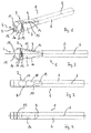
- An inventive holder for a medical, in particular surgical instrument is shown in the figures in various (partial) views and generally designated by the reference numeral 1.
- the holder 1 in this embodiment is elongated formed with a shank portion 2.
- a quick coupling 3 is formed, which serves to receive an undercut having a connecting end of an instrument shaft of the medical instrument, with which the holder is to be connected ,
- the quick coupling 3 has a main body 26 and on whose end face 4 a receiving opening 5, which has the shape of a guided along a longitudinal axis 6 of the holder 1 bore.
- the quick coupling 3 is in particular formed in one piece and has two flattened side surfaces 7 and 8 and extending between these narrow sides 9 and 10, which extend wedge-shaped opening to one of the front side 4 nearby section, from where the narrow side 9, 10 rejuvenate , There go the narrow sides 9, 10 in two on the front side 4 protruding projections 11 and 12, respectively.
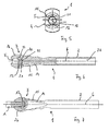
- a coupling plate 13 is formed by corresponding cutouts of the integral material of the quick coupling 3 and connected on one side with a separated by a slot 14 of the main body 26 of the quick coupling 3 spring bridge 15.
- the spring bridge 15 is integrally connected to the main body 26 of the quick coupling 3.
- the spring bridge 15 has a flattening 16 on its surface located on the narrow side 9, which flattening is formed as an ergonomic or haptic element for the plant of the thumb of a hand.
- handle recesses 17, 18, 19 are formed on the opposite Narrow side 10 handle recesses 17, 18, 19 are formed. These serve the plant of fingers, in particular index fingers, middle fingers and ring fingers of the hand, whose thumb rests in the flat 16.
- the spring tongue 14 can be deflected in the direction of the opposite narrow side 10 with one hand in order to effect a longitudinal displacement of the coupling plate 13 in the same direction.
- Clutch plate 13 and spring bridge 15 are, as already mentioned, integrally connected to each other and enclose an angle, so that the coupling plate 13 substantially perpendicular to the longitudinal axis 6 and thus the direction of the guided along this axis bore of the receiving opening 5.
- the coupling plate 13 is located in a receiving slot 27, which is in the quick coupling 3, more precisely in the main body 26, is formed, and at an angle to the slot 14 extends. In the receiving slot 27, the clutch plate 13 can move in a longitudinal direction.
- the receiving slot 27 and the slot 14 are at an angle to each other and together form an approximately L-shaped slot.
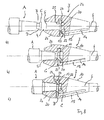
- a passage opening 20 is formed in the coupling plate 13, as in particular in the Fig. 6 can be seen.
- This passage opening 20 extends in its orientation also in the axial direction, ie with an extension direction parallel to the longitudinal axis 6, but is in the in Fig. 6 shown position in which the spring bridge 15 can be seen in an initial or rest position, with its central axis 21 relative to the longitudinal axis 6, which also forms the central axis of the receiving opening 5, offset.
- the receiving opening 5 extends beyond the portion in which the coupling plate 13 traverses them, up to an end portion 22.
- This can also be seen again in the front view according to Fig. 5 in which the offset axes of the central axis 21 and the longitudinal axis 6 are shown, as well as a view of the receiving opening 5 through which to be recognized by section of the coupling plate thirteenth
- Fig. 6 is also seen that in the shaft portion 2 of the holder 1 formed as a blind hole receptacle 23 is formed for connecting the holder 1 according to the invention with other structures, such as the drive shaft of a motorized instrument drive with a rotary drive or with a, for example, as transverse to the longitudinal extent of the holder 1, that is transverse to the longitudinal axis 6, in particular perpendicular to this, T-handle is used.
- other structures such as the drive shaft of a motorized instrument drive with a rotary drive or with a, for example, as transverse to the longitudinal extent of the holder 1, that is transverse to the longitudinal axis 6, in particular perpendicular to this, T-handle is used.
- the quick coupling 3 of the holder 1 according to the invention is for connection to a terminal end A (see. Fig. 7 ) of a staff of instruments.
- the quick coupling 3 or the connection end A is formed in particular as a so-called Hudson connection or a corresponding connection coupling.
- the quick coupling 3 of the holder is shown with the spring bridge 15 in a relaxed home or rest position.
- the receiving opening 5 and the passage opening 20 are not aligned in the coupling plate 13 in exact alignment.
- a section 24 of the coupling plate 13 which delimits the passage opening 20 protrudes into the region of the receiving opening 5 and thus covers in particular its end section 22.
- the coupling plate 13 has one of the front side 4 facing run-on slope 25 provided.
- connection end A of the instrument shaft has at its free end a region B of tapered diameter and a cover that covers this C.
- An undercut D is formed on this.
- the effect of the starting slope is sufficient 25 in conjunction with the conclusion C not to let the clutch plate 13 so far dodge in the direction of the narrow side 10 that the passage opening 20 is passable for the conclusion C, so here can be helped by hand by the spring bridge 15 by closing the Slot 14 is pressed in the direction of the opposite narrow side 10.
- the coupling plate 13 driven by the spring force of the spring bridge 15, can snap back into its rest or initial position.
- the portion 24 which lies above the undercut D at the terminal end A locks the terminal end A in the axial direction, i. in the direction of the longitudinal axis 6 of the holder.
- the spring bridge 15 has pressed in the direction of the opposite narrow side 10, thereby the coupling plate 13 are moved so that the passage opening 20 is exposed for a passage of the conclusion C and the terminal end A can be removed.
Abstract
Description
Die vorliegende Erfindung betrifft einen Halter für ein medizinisches, insbesondere chirurgisches Instrument mit einer Schnellkupplung für die Aufnahme eines einen Hinterschnitt aufweisenden Anschlussendes eines Instrumentenschafts des medizinischen Instrumentes, wobei die Schnellkupplung ein erstes Kupplungselement mit einer ersten axialen Durchgangsöffnung für das Anschlussende aufweist.The present invention relates to a holder for a medical, in particular surgical instrument with a quick coupling for receiving an undercut connection end of an instrument shaft of the medical instrument, wherein the quick coupling has a first coupling element with a first axial passage opening for the connection end.
Ein solcher Halter dient der zumindest axial gehaltenen Festlegung eines medizinischen Instrumentes für dessen Einsatz und Gebrauch. Die axiale Festlegung kann dabei eine solche sein, die ein axiales Spiel zwischen dem Halter und dem Instrument ermöglicht, das Instrument jedoch sicher an dem Halter festlegt, ohne dass es sich in axialer Richtung von dem Halter etwa unbeabsichtigt löst. In vielen Fällen müssen mit dem Halter - sei es über einen motorischen Antrieb erzeugte oder sei es manuell aufgebrachte - Kräfte nicht nur in axialer Richtung, sondern auch für einen rotatorischen Antrieb des medizinischen Instrumentes übertragen werden. In solchen Fällen sind bei entsprechenden Haltern zusätzlich auch Mittel für eine verdrehfeste Aufnahme des medizinischen Instrumentes und Verbindung desselben mit dem Halter vorgesehen.Such a holder is used to hold at least an axial definition of a medical instrument for its use and use. The axial fixation can be one which allows axial play between the holder and the instrument, but securely fixes the instrument to the holder without it becoming unintentionally detached from the holder in the axial direction. In many cases, with the holder - be it generated by a motor drive or manually applied - forces are transmitted not only in the axial direction, but also for a rotary drive of the medical instrument. In such cases, additional means for a rotationally fixed recording of the medical instrument and connection of the same with the holder are provided with appropriate holders.
Ein medizinisches Instrument im Sinne der vorliegenden Beschreibung und Erfindung kann insbesondere ein medizinisch eingesetztes Werkzeug, wie ein Bohrer, eine Fräse, eine Raspel, eine Ahle, eine Säge oder dgl. sein. Unter einem chirurgischen Instrument sind hier aber auch Bestandteile von Implantaten oder vollständige Implantate zu verstehen, seien dies Implantate als Bestandteile von Prothesen, insbesondere auch Endoprothesen, oder sonstige mit einem Halter für deren Handhabung beim Setzen, Entfernen oder Versetzen oder sonstigen Schritten zu verbindende Implantate.A medical instrument in the sense of the present description and invention may in particular be a medically used tool such as a drill, a milling cutter, a rasp, an awl, a saw or the like. However, a surgical instrument here also means components of implants or complete implants, whether implants as components of prostheses, in particular endoprostheses, or other implants to be connected to a holder for their handling during setting, removal or displacement or other steps.
Ein gattungsgemäßer Halter ist beispielsweise in der
Weitere Ansätze, die jedoch einen schaftartigen Halter mit chirurgischen Instrumenten in anderer Weise verbinden, sind in der
Insbesondere dann, wenn - wie bei derartigen Haltern in der Regel üblich - solche Halter mit einem daran angeordneten medizinischen Instrument im Verlaufe eines operative Eingriffes eingesetzt werden, werden regelmäßig nicht nur das medizinische Instrument selbst, sondern auch der Halter, insbesondere der Bereich der Schnellkupplung verunreinigt, beispielsweise mit Blut und anderen Körperflüssigkeiten, während der Operation gelösten Gewebebestandteilen, Knochenspäne und -splittern oder dgl. Da solche Halter regelmäßig nicht für einen einmaligen Gebrauch bestimmt, sondern wieder verwendbare Gerätschaften sind, müssen sie nach entsprechendem Einsatz gereinigt und sterilisiert werden, bevor sie erneut verwendet werden können. Dabei stellen die in bekannten Schnellkupplungen vorbeschriebener Halter enthaltenen Kleinteile und insbesondere auch die gering dimensionierten Spalten und Räume zwischen derartigen Teilen bei der rückstandslosen Reinigung und vollständigen Sterilisierung regelmäßig eine besondere Herausforderung dar. Sind nämlich derartige Schnellkupplungen der Halter zerlegbar gestaltet, so müssen hier von dem für die Reinigung und Sterilisierung zuständigen Personal diese Schnellkupplungen nicht nur zerlegt, sondern die Kleinteile auch behutsam für die Reinigung und Sterilisierung gehandhabt und im Anschluss die Schnellkupplungen wieder ordnungsgemäß zusammengefügt werden. Sind hingegen die Schnellkupplungen nicht zerlegbar, so ist es häufig sogar unmöglich, kleine und kleinste Spalten und Zwischenräume, wie sie beispielsweise im Bereich des Sitzes von Verriegelungskugeln auftreten, rückstandsfrei zu reinigen und zu sterilisieren. Dort verbergen sich somit stets mögliche Gefahrenherde von Verunreinigungsrückständen, die bei einem nachfolgenden Gebrauch des Halters im Zuge eines weiteren medizinischen Eingriffes zu Komplikationen führen können.In particular, when - as in such holders usually usual - such holders are used with a medical instrument disposed thereon in the course of surgery, regularly not only the medical instrument itself, but also the holder, especially the area of the quick coupling contaminated For example, with blood and other body fluids, tissue components, bone chips and splinters or the like loosened during surgery. Since such holders are not regularly intended for single use but are reusable equipment after proper use, they can be cleaned and sterilized before they can be reused. In this case, the small parts and in particular the small-sized gaps and spaces between such parts in the residue-free cleaning and complete sterilization regularly present a special challenge in the above-described holders in the above-described holder holders. Namely, such quick couplings of the holder designed separable, so must from the for cleaning and sterilizing personnel not only dismantle these quick-release couplings, but also gently handle the hardware for cleaning and sterilization, and then properly reassemble the quick-release couplings. If, on the other hand, the quick-release couplings can not be dismantled, it is often even impossible to clean and sterilize residue-free small and smallest gaps and gaps, as occur, for example, in the region of the seat of locking balls. There, therefore, always hide potential sources of contamination residues, which can lead to complications in subsequent use of the holder in the course of further medical intervention.
Es ist daher Aufgabe der vorliegenden Erfindung, einen bekannten und gattungsgemäßen Halter für ein medizinisches, insbesondere chirurgisches Instrument dahingehend weiterzubilden, dass dieser einen gegenüber herkömmlichen Haltern vereinfachten Aufbau aufweist und in der nachgebräuchlichen Nachsorge einfach zu reinigen und zu sterilisieren ist.It is therefore an object of the present invention to further develop a known and generic holder for a medical, in particular surgical instrument to the effect that this has a simplified structure compared to conventional holders and is easy to clean and sterilize in the post-operative care.
Diese Aufgabe wird gelöst durch einen Halter für ein medizinisches, insbesondere chirurgisches Instrument mit den Merkmalen des Patentanspruches 1. Vorteilhafte Weiterbildungen eines solchen Halters sind in den abhängigen Ansprüchen 2 bis 8 angegeben. Einen weiteren Aspekt einer Lösung der erfindungsgemäßen Aufgabe besteht sodann in einer Kombination aus einem wie angegebenen, neuartigen Halter und wenigsten einem in dem Halter lösbar festlegbaren medizinischen Instrument mit den Merkmalen des Anspruches 9 sowie entsprechende vorteilhafte Weiterbildungen gemäß der Ansprüche 10 und 11. Erfindungsgemäß hat also ein neuartiger Halter für ein medizinisches, insbesondere chirurgisches, Instrument eine Schnellkupplung für die Aufnahme eines einen Hinterschnitt aufweisenden Anschlussendes eines Instrumentenschafts des medizinischen Instrumentes. Die Schnellkupplung weist ein erstes Kupplungselement mit einer ersten axialen Durchgangsöffnung für das Anschlussende auf. Sie weist ferner ein zweites Kupplungselement auf mit einer zweiten axialen Durchgangsöffnung für das Anschlussende. Erstes und zweites Kupplungselement sind relativ zueinander in einer Richtung quer zu der axialen Richtung der Durchgangsöffnung bewegbar aus einer Riegelstellung, in der die erste und die zweite Durchgangsöffnung dergestalt zueinander versetzt sind, dass ein Rand der zweiten Durchgangsöffnung einen Hinterschnitt an dem Anschlussende des Instrumentenschafts verriegelnd hintergreift, in eine Freigabestellung, in der die erste und die zweite axiale Durchgangsöffnung zumindest so weit in Flucht liegen, dass das Anschlussende durch beide Durchgangsöffnungen frei hindurchgeführt werden kann. Ferner sind erfindungsgemäß das erste und das zweite Kupplungselement über einer Federbrücke einstückig miteinander verbunden, und die Federbrücke spannt das erste und das zweite Kupplungselement relativ zueinander in die Riegelstellung vor.This object is achieved by a holder for a medical, in particular surgical instrument having the features of
Bei einer derartigen Ausgestaltung des Halters in seiner Schnellkupplung entfällt zunächst das Erfordernis, kleinteilige und gesonderte Riegelelemente, wie etwa Riegelkugeln, vorzusehen. Die Verriegelungswirkung wird allein durch den Versatz der beiden Durchgangsöffnungen in dem ersten und dem zweiten Kupplungselement bewirkt, den diese in der aufgrund der Vorspannung als Normalstellung eingenommenen Riegelstellung zueinander in eine Richtung quer zur axialen Erstreckung aufweisen. Mit anderen Worten ist hierbei ein mit dem Anschlussende seines Instrumentenschafts durch die erste Durchgangsöffnung hindurch geführtes medizinisches Instrument zunächst einmal durch diese Durchgangsöffnung in radialer Richtung festgelegt. Eine axiale Fixierung bzw. Verriegelung erfolgt dadurch, dass das Anschlussende auch die zweite Durchgangsöffnung durchragt, wobei die zweite Durchgangsöffnung gegenüber der ersten Durchgangsöffnung quer zur axialen Richtung derart verschoben ist, dass sie mit ihrem Rand an einem Hinterschnitt des Anschlussendes anliegt, diesen hintergreift und somit den Instrumentenschaft in axialer Richtung verriegelt. Wie oben bereits erwähnt, kann bei dieser Verriegelungsstellung weiterhin ein gewisses axiales Spiel vorhanden sein. Häufig ist ein solches axiales Spiel, jedenfalls bei handbetriebenen Haltern, von den Anwendern sogar gewünscht, da es eine zusätzliche taktile Hilfe gibt. In anderen Fällen, beispielsweise bei Instrumenten zum Durchbohren harten Knochens im Bereich der Schädeldecke, ist ein solches axiales Spiel erforderlich, da eine Drehmitnahme eines Antriebes nur in einer axial nach hinten verschobenen Stellung des Instrumentenschafts greift, die gegen eine Federlast und beim Andrücken des Instrumentes auf die zu durchbohrende Schädeldecke eingenommen wird, diese Stellung dann jedoch, wenn die Schädeldecke durchbohrt ist, entspannt, die Feder den Drehantrieb stoppt und somit das Bohrwerkzeug auskuppelt. Damit wird verhindert, dass der Bohrantrieb weiter besteht und eine Verletzung der unterhalb der Schädeldecke liegenden Weichgewebeteile oder des Gehirns erfolgt.In such an embodiment of the holder in its quick coupling initially eliminates the need small-scale and separate locking elements, such as locking balls to provide. The locking effect is effected solely by the offset of the two passage openings in the first and the second coupling element, which they have in the position assumed by the bias as a normal position locking position to each other in a direction transverse to the axial extent. In other words, in this case, a medical instrument guided through the first passage opening with the connection end of its instrument shaft is first of all set in the radial direction through this passage opening. An axial fixation or locking takes place in that the connecting end also projects through the second passage opening, wherein the second passage opening is displaced transversely to the axial direction relative to the first passage opening so that it rests with its edge on an undercut of the connection end, this engages behind and thus locking the instrument shaft in the axial direction. As already mentioned above, a certain axial play can still be present in this locking position. Often, such axial play, at least for hand-operated holders, is even desired by users because there is additional tactile help. In other cases, such as instruments for piercing hard bone in the skull, such an axial clearance is required because a rotational drive of a drive engages only in an axially rearwardly shifted position of the instrument shaft, against a spring load and when pressing the instrument on the skull to be pierced is taken, this position but then when the skull is pierced, relaxed, the spring stops the rotary drive and thus disengages the drill. This will prevent the drill drive from continuing to injure the soft tissues or the brain below the cranium.
Der weiterhin gegebene Vorteil des erfindungsgemäßen Halters besteht darin, dass dieser in seiner Verbindung zwischen erstem und zweitem Kupplungselement einstückig gebildet ist. Auch dadurch entfällt hier eine mögliche Zerlegung in Einzelteile und Kleinteile, die beim Reinigen und Sterilisieren des Halters erforderlich wäre. Zudem können bei entsprechender und insbesondere bevorzugter Konstruktion und Ausgestaltung des Halters, insbesondere seiner Schnellkupplung, entsprechende Zwischenräume zwischen den miteinander einstückig verbundenen Elementen geschaffen sein, die sich mit einem entsprechenden Reinigungsinstrumentarium gut erreichen, reinigen und anschließend sterilisieren lassen. So können insbesondere äußerst schmale Zwischenräume vermieden werden, wie sie beispielsweise an Kugellagerflächen von Verriegelungskugeln gegeben sind und die beim Reinigen und Sterilisieren kaum vollständig und für eine gründliche Reinigung und Sterilisierung ausreichend erreichbar sind.The continued advantage of the holder according to the invention is that it is integrally formed in its connection between the first and second coupling element. This also eliminates a possible disassembly into individual parts and small parts that would be required when cleaning and sterilizing the holder. In addition, with appropriate and particularly preferred construction and design of the holder, in particular its quick coupling, corresponding gaps between the elements integrally connected to each other can be created, which can be easily reached, cleaned and then sterilized with a corresponding cleaning instruments. Thus, in particular extremely narrow interstices can be avoided, as they are given for example on ball bearing surfaces of locking balls and the cleaning and sterilization are hardly complete and sufficiently accessible for thorough cleaning and sterilization.
Die Schnellkupplung kann mit Vorteil insgesamt einstückig gebildet sein und besteht bevorzugt aus einem leicht sterilisierbaren und für den operativen Einsatz ausreichend biokompatiblen Material, wie insbesondere einem medizinisch verträglichen Edelstahl. Die Verwendung eines solchen Metalls (es kämen auch andere medizinisch verwendbare Metalle wie Titan oder Titanlegierungen in Betracht) ist auch deshalb von Vorteil, da sich mit solchem Material mit vergleichsweise dünnwandiger Bauweise eine eine ausreichende Rückstellkraft in Richtung der Riegelstellung ausbildende Federbrücke als einstückige Verbindung zwischen dem ersten und dem zweiten Kupplungselement realisieren lässt.The quick coupling may advantageously be formed in one piece as a whole and preferably consists of an easily sterilizable and sufficiently biocompatible material for operative use, in particular a medically compatible stainless steel. The use of such a metal (there would be others medically usable metals such as titanium or titanium alloys into consideration) is also advantageous because can be realized with such material with comparatively thin-walled construction a sufficient restoring force in the direction of the bolt position spring bridge formed as a one-piece connection between the first and the second coupling element.
Der erfindungsgemäße Halter kann in seiner Schnellkupplung mit Vorteil zudem Sperrstrukturen aufweisen zum Zusammenwirken mit Gegenstrukturen an dem Anschlussende des Instrumentenschaftes für eine verdrehfeste Anordnung des Instruments in dem Halter. Eine derartige Ausgestaltung ist insbesondere dann relevant, wenn mit dem Halter Drehkräfte bzw. Drehmomente auf das medizinische Instrument, z.B. einen Bohrer oder eine Reibahle, zu übertragen sind. Eine mögliche Ausgestaltung, derartige Sperrstrukturen zu bilden, besteht darin, an der Schnellkupplung an einer außen liegenden Stirnseite des ersten Kupplungselementes auf einander gegenüberliegenden Seiten der die Oberfläche an der Stirnseite durchbrechenden Durchgangsöffnung Seitenbacken anzuordnen, die von der Oberfläche an der Stirnseite nach außen abstehen und die die Sperrstrukturen bildende, zueinander parallele und einander zugewandte ebene Anlageflächen aufweisen. Diese Anlageflächen sind dabei für die Anlage an an dem Anschlussende des Instrumentenschaftes ausgebildeten, die Gegenstrukturen bildenden Gegenflächen vorgesehen.The holder according to the invention can also advantageously have locking structures in its quick-action coupling for interacting with counter-structures at the connection end of the instrument shaft for a rotationally fixed arrangement of the instrument in the holder. Such a configuration is particularly relevant when with the holder rotational forces or torques on the medical instrument, e.g. a drill or a reamer, are to be transferred. One possible embodiment of forming such blocking structures is to arrange on the quick coupling on an outer end face of the first coupling element on opposite sides of the through opening on the front side through opening side jaws, which protrude from the surface on the front side to the outside and the Having the locking structures forming, parallel to each other and facing each other planar contact surfaces. In this case, these abutment surfaces are provided for abutment with mating surfaces formed at the connection end of the instrument shaft and forming counter-structures.
In einer bevorzugten Ausgestaltung des erfindungsgemäßen Halters weist die Schnellkupplung einen Grundkorpus auf, an dem das erste und das zweite Kupplungselement angeformt, insbesondere mit diesem einstückig gebildet, sind, wobei in dem Grundkorpus eine Ausnehmung vorgesehen ist, die einseitig durch eine Wand des Grundkorpus begrenzt ist und entlang derer sich auf einer der Wand gegenüberliegenden Seite die Federbrücke und zu dieser abgewinkelt das zweite Kupplungselement erstreckt. Diese Ausgestaltung ist eine besonders einfach aufgebaute, in ihrer Struktur einfach zu bildende Gestaltungsvariante, die zugleich die Erfordernisse der einfachen Reinigbarkeit und Sterilisierbarkeit des Halters insbesondere im Bereich seiner Schnellkupplung erfüllt. Denn insbesondere dann, wenn die Ausnehmung ausreichend groß dimensioniert ist, der Zwischenraum zwischen der Wand des Grundkorpus und der Federbrücke für die Einführung von Reinigungsgerätschaften hinreichend weit bemessen ist, kann dieser Abschnitt einfach gereinigt und sterilisiert werden. Dabei kann, muss indes nicht zwangsläufig, die Ausnehmung ebenfalls winkelförmig sein, dabei insbesondere in ihrem Verlauf der Winkelform des Verlaufes der Federbrücke und des abgewinkelt zu diesem verlaufenden zweiten Kupplungselementes folgen.In a preferred embodiment of the holder according to the invention, the quick coupling on a base body on which the first and second coupling element formed, in particular integrally formed therewith, wherein in the base body a recess is provided which is bounded on one side by a wall of the base body and along which extends on a side opposite the wall, the spring bridge and angled to the second coupling element. This embodiment is a particularly simply constructed, easy-to-form in its structure design variant, which also meets the requirements of easy cleanability and sterilizability of the holder, especially in the field of quick release. For in particular when the recess is sufficiently large, the gap between the wall of the main body and the spring bridge for the introduction of cleaning equipment is sufficiently far dimensioned, this section can be easily cleaned and sterilized. It may, but not necessarily, the recess also be angular, in particular follow in its course the angular shape of the course of the spring bridge and the angled extending to this second coupling element.
Ferner kann es gemäß einer vorteilhaften Ausgestaltungsvariante des erfindungsgemäßen Halters von Vorteil sein, wenn die Ausnehmung einen Rücksprung und das zweite Kupplungselement einen Vorsprung (selbstverständlich auch in umgekehrter Gestaltung, also einen Vorsprung an der Ausnehmung und einen Rücksprung an dem Kupplungselement) aufweisen, die zusammen einen eine über die Riegelstellung hinausgehende Relativbewegung der Kupplungselemente verhindernden Anschlag bilden. Ein solcher Anschlag verhindert Fehlbedienungen und erhöht insgesamt die Stabilität und Zuverlässigkeit des erfindungsgemäßen Halters.Furthermore, according to an advantageous embodiment variant of the holder according to the invention, it may be advantageous if the recess has a recess and the second coupling element has a projection (of course also in the reverse configuration, ie a projection on the recess and a recess on the coupling element), which together form a projection form a stop above the locking position relative movement of the coupling elements preventing stop. Such a stop prevents incorrect operation and increases the overall stability and reliability of the holder according to the invention.
Gemäß einer weiteren vorteilhaften Ausgestaltung der Erfindung kann die Federbrücke auf einer seitlichen Außenseite des Halters liegen und dabei derart gestaltet sein, dass auf diese manuell eine quer zu ihrer Längserstreckung und entgegen der Federwirkung der Federbrücke wirkende Kraft, insbesondere eine Druckkraft, aufgebracht werden kann, zum Verlagern des zweiten Kupplungselementes aus der Riegelstellung in die Freigabestellung. Mit anderen Worten ist die Federbrücke hier zugleich ein "Druckschalter", durch dessen Betätigung die Relativposition des ersten und des zweiten Kupplungselementes zueinander aus der Riegelstellung in die Freigabestellung überführt werden kann, um in dieser Position insbesondere ein mit dem Halter verbundenes Instrument von dem Halter zu lösen, ggf. auch ein Instrument mit den Anschlussende des Instrumentenschafts in die Schnellkupplung des Halters einzuführen und daran festzulegen.According to a further advantageous embodiment of the invention, the spring bridge may lie on a lateral outer side of the holder and thereby be designed so that a force acting transversely to its longitudinal extent and against the spring action of the spring bridge force, in particular a compressive force can be applied to this manually, for Relocating the second coupling element from the latch position to the release position. In other words, the spring bridge is at the same time a "pressure switch", by the operation of the relative position of the first and the second coupling element to each other from the latch position can be transferred to the release position to in this position in particular a connected to the holder instrument from the holder If necessary, also insert an instrument with the connecting end of the instrument shaft into the quick coupling of the holder and fix it.
Der Halter kann insbesondere ein manuell zu betätigender Halter sein mit einem Drehschaft, an welchen an einem freien Ende die Schnellkupplung angeordnet ist und an welchem ferner an einem dem freien Ende gegenüberliegenden Ende T-förmig ein Griffteil angeordnet ist. Die Erfindung ist aber nicht auf einen derartigen Halter beschränkt, ein erfindungsgemäßer Halter kann auch in anders geformten manuell zu bedienenden Gestaltungsformen verwirklicht werden, wie er auch als Bestandteil eines motorisch betriebenen Instrumententriebes, sei es ein in axialer Richtung betätigter Antrieb, sei es ein rotatorisch betriebener Antrieb, verwirklicht sein kann.The holder may in particular be a manually operable holder with a rotary shaft on which at a free end of the quick coupling is arranged and which also at an opposite end of the free end T-shaped a handle part is arranged. However, the invention is not limited to such a holder, an inventive holder can be realized in other shaped manually operated designs, as it is also part of a motor-driven instrument drive, be it an actuated in the axial direction drive, be it a rotationally operated Drive, can be realized.
In einem weiteren Aspekt der Erfindung besteht diese in einer Kombination aus einem wie oben näher beschriebenen Halter und wenigsten einem an dem Halter lösbar festlegbaren medizinischen, insbesondere chirurgischen Instrument, welches einen ein Anschlussende aufweisenden Instrumentenschaft beinhaltet und bei dem an dem Anschlussende des Instrumentenschafts ein Hinterschnitt ausgebildet ist. Dabei ist die Kombination nicht beschränkt auf einen Halter und ein einziges Instrument, es kann eine solche zugleich auch ein Set bestehend aus einem oder mehreren Haltern und einem oder mehreren medizinischen Instrumenten umfassen.In a further aspect of the invention, this consists of a combination of a holder as described in more detail above and at least one medical, in particular surgical, instrument detachably fixable on the holder, which contains an instrument shaft having a connection end and in which an undercut is formed at the connection end of the instrument shaft is. The combination is not limited to a holder and a single instrument, it may at the same time also include a set consisting of one or more holders and one or more medical instruments.
Bei einer solchen Kombination kann es von Vorteil sein, wenn, wie gemäß einer vorteilhaften Ausgestaltung der Erfindung angegeben, das Instrument an dem Anschlussende seines Instrumentenschafts eine sich von dem freien Ende des Instrumentenschafts her im weiteren, von dem freien Ende weg weisenden Verlauf konisch aufweitende Verdickung aufweist, die an ihrem dem freien Ende abgewandten Endabschnitt unter Ausbildung des Hinterschnitts zurückfällt, auf einen geringeren Umfang des Instrumentschafts. Diese konische Verdickung dient einem einfacheren Einführen des Anschlussendes des Instrumentenschafts in die Schnellkupplung, da durch den konischen Abschnitt beim Aufbringen einer in axialer Richtung gerichteten Druckkraft auf den Instrumentenschaft das zweite Kupplungselement der Schnellkupplung aus der Riegelstellung verdrängt und in die Freigabestellung bewegt wird, bis der hinter dem Konus liegende Hinterschnitt erreicht wird, der Durchmesser des Instrumentenschafts zurückfällt und das zweite Kupplungselement in die Riegelstellung schnappt.In such a combination, it may be advantageous if, as indicated according to an advantageous embodiment of the invention, the instrument at the terminal end of its instrument shaft, a thickening tapering away from the free end of the instrument shaft further, pointing away from the free end has, which falls back at its end remote from the free end to form the undercut, to a lesser extent of the instrument shaft. This conical thickening is used for easier insertion of the connecting end of the instrument shaft in the quick coupling, as displaced by the conical portion when applying an axially directed pressure force on the instrument shaft, the second coupling element of the quick coupling from the locking position and moved to the release position until the rear the cone lying undercut is achieved, the diameter of the instrument shaft falls back and the second coupling element snaps into the locking position.
Für eine Übertragung von Drehkräften bzw. Drehmomenten ist es von Vorteil, wenn das Instrument einer solchen Kombination an seinem Anschlussende des Instrumentenschafts die Gegenflächen bildende, parallele Abflachungen aufweist.For a transmission of rotational forces or torques, it is advantageous if the instrument of such a combination at its connection end of the instrument shaft has the mating surfaces forming parallel flats.
Weitere Vorteile und Merkmale der Erfindung ergeben sich aus der nachfolgenden Beschreibung eines Ausführungsbeispiels anhand der beigefügten Figuren. Dabei zeigen:
- Fig. 1
- ein Ausführungsbeispiel eines erfindungsgemäßen Halters für ein medizinisches, insbesondere chirurgisches Instrument in einer perspektivischen Darstellung schräg von einer die Schnellkupplung aufweisenden Seite her;
- Fig. 2
- den Halter aus
Fig. 1 in einer Seitenansicht mit Blick auf eine Seitenfläche der Schnellkupplung; - Fig. 3
- den Halter aus
Fig. 1 in einer Seitendarstellung mit Blick auf eine erste Schmalseite; - Fig. 4
- den Halter aus
Fig. 1 in einer Seitendarstellung mit Blick auf eine weitere, der inFig. 3 gezeigten Schmalseite gegenüberliegenden Schmalseite; - Fig. 5
- eine Vorderansicht des Halters gemäß
Fig. 1 von der Kupplungsseite der Schnellkupplung her in vergrößerter Darstellung; - Fig. 6
- eine Längsschnittdarstellung durch den Halter gemäß
Fig. 1 ; - Fig. 7
- den Halter gemäß
Fig. 1 mit darin aufgenommenem Anschlussende eines medizinischen Instrumentes in teilgeschnittener Darstellung; und - Fig. 8
- in drei Darstellungen a bis c vergrößert den Abschnitt des Halters gemäß
Fig. 1 mit der Schnellkupplung beim Einführen eines Anschlussendes eines medizinischen Instrumentes zum Festlegen desselben an dem Halter.
- Fig. 1
- an embodiment of a holder according to the invention for a medical, in particular surgical instrument in a perspective view obliquely from a quick coupling having side;
- Fig. 2
- the holder off
Fig. 1 in a side view looking at a side surface of the quick coupling; - Fig. 3
- the holder off
Fig. 1 in a page view overlooking a first narrow side; - Fig. 4
- the holder off
Fig. 1 in a page view overlooking another, the inFig. 3 shown narrow side opposite narrow side; - Fig. 5
- a front view of the holder according to
Fig. 1 from the coupling side of the quick coupling forth in an enlarged view; - Fig. 6
- a longitudinal sectional view through the holder according to
Fig. 1 ; - Fig. 7
- the holder according to
Fig. 1 with therein received end of a medical instrument in a partially sectioned view; and - Fig. 8
- in three illustrations a to c increases the portion of the holder according to
Fig. 1 with the quick coupling during insertion of a connection end of a medical instrument for fixing the same to the holder.
In den Figuren ist ein beispielhaftes Ausführungsbeispiel eines erfindungsgemäßen Halters gezeigt und wird nachstehend näher erläutert. Die Figuren sind dabei nicht als vollständige Konstruktionszeichnungen anzusehen, sie beschränken sich vielmehr auf die Darstellung der erfindungswesentlichen und weiterer relevanter Merkmale des Ausführungsbeispiels eines erfindungsgemäßen Halters.In the figures, an exemplary embodiment of a holder according to the invention is shown and will be explained in more detail below. The figures are not to be regarded as complete construction drawings, they are rather limited to the representation of essential to the invention and other relevant features of the embodiment of a holder according to the invention.
Ein erfindungsgemäßer Halter für ein medizinisches, insbesondere chirurgisches Instrument ist in den Figuren in verschiedenen (Teil-) Ansichten gezeigt und allgemein mit dem Bezugszeichen 1 bezeichnet.An inventive holder for a medical, in particular surgical instrument is shown in the figures in various (partial) views and generally designated by the
Der Halter 1 in diesem Ausführungsbeispiel ist langgestreckt geformt mit einem Schaftabschnitt 2. An einem stirnseitigen Ende dieses Schaftabschnittes 2 ist eine Schnellkupplung 3 angeformt, die der Aufnahme eines einen Hinterschnitt aufweisenden Anschlussendes eines Instrumentenschaftes des medizinischen Instrumentes, mit welchem der Halter zu verbinden ist, dient.The
Die Schnellkupplung 3 weist einen Hauptkorpus 26 und an dessen Stirnseite 4 eine Aufnahmeöffnung 5 auf, die die Form einer entlang einer Längsachse 6 des Halters 1 geführten Bohrung hat. Die Schnellkupplung 3 ist insbesondere einstückig gebildet und weist zwei abgeflachte Seitenflächen 7 und 8 auf sowie zwischen diesen verlaufende Schmalseiten 9 und 10, die sich keilförmig öffnend auseinander verlaufen zu einem der Stirnseite 4 nahegelegenen Abschnitt, von wo aus sich die Schmalseite 9, 10 wieder verjüngen. Dort gehen die Schmalseiten 9, 10 in zwei an der Stirnseite 4 vorstehende Vorsprünge 11 bzw. 12 über.The
Eine Kupplungsplatte 13 ist durch entsprechende Ausschnitte aus dem einstückigen Material der Schnellkupplung 3 herausgeformt und einseitig mit einer durch einen Schlitz 14 von dem Hauptkorpus 26 der Schnellkupplung 3 getrennten Federbrücke 15 verbunden. In einem der Stirnseite 4 axial gegenüberliegenden Bereich, in dem der Schlitz 14 endet, ist die Federbrücke 15 mit dem Hauptkorpus 26 der Schnellkupplung 3 einstückig verbunden. Die Federbrücke 15 weist eine Abflachung 16 auf ihrer an der Schmalseite 9 gelegenen Oberfläche auf, welche Abflachung als ergonomisches bzw. haptisches Element für die Anlage des Daumens einer Hand ausgebildet ist. Auf der gegenüberliegenden Schmalseite 10 sind Griffmulden 17, 18, 19 ausgebildet. Diese dienen der Anlage von Fingern, insbesondere Zeigefinger, Mittelfinger und Ringfinger der Hand, deren Daumen in der Abflachung 16 ruht. So kann mit einer Hand die Federzunge 14 in Richtung der gegenüberliegenden Schmalseite 10 ausgelenkt werden, um damit eine Längsverschiebung der Kupplungsplatte 13 in selbiger Richtung zu bewirken. Kupplungsplatte 13 und Federbrücke 15 sind, wie bereits erwähnt, einstückig miteinander verbunden und schließen einen Winkel ein, so dass die Kupplungsplatte 13 im Wesentlichen senkrecht zu der Längsachse 6 und mithin der Richtung der als entlang dieser Achse geführten Bohrung der Aufnahmeöffnung 5 verläut. Die Kupplungsplatte 13 liegt in einem Aufnahmeschlitz 27, der in der Schnellkupplung 3, genauer in deren Hauptkorpus 26, ausgeformt ist, und in einem Winkel zu dem Schlitz 14 verläuft. In dem Aufnahmeschlitz 27 kann sich die Kupplungsplatte 13 in einer Längsrichtung bewegen. Der Aufnahmeschlitz 27 und der Schlitz 14 liegen in einem Winkel zueinander und bilden gemeinsam einen etwa L-förmigen Schlitz.A
In der Kupplungsplatte 13 ist, wie insbesondere in der
In
Die Schnellkupplung 3 des erfindungsgemäßen Halters 1 ist zur Verbindung mit einem Anschlussende A (vgl.
Die Vorgehensweise beim Verbinden des Anschlussendes A mit der Schnellkupplung 3 des Halters 1 ist in den drei Darstellungen und Skizzen der
In einem ersten, in der
Das Anschlussende A des Instrumentenschaftes hat an seinem freien Ende einen Bereich B verjüngten Durchmessers und einen diesen überdeckenden Abschluss C. An diesem ist ein Hinterschnitt D gebildet. Wird nun, wie in
Hat der Abschluss C die Durchtrittsöffnung 20 in der Kupplungsplatte 13 vollständig passiert, gelangt er in den Endabschnitt 22 der Aufnahmeöffnung 5, und die Kupplungsplatte 13 kann, getrieben durch die Federkraft der Federbrücke 15, zurückschnappen in ihre Ruhe- bzw. Ausgangsposition. In dieser Position verriegelt der Abschnitt 24, der über den Hinterschnitt D an dem Anschlussende A liegt, das Anschlussende A in axialer Richtung, d.h. in Richtung der Längsachse 6 des Halters. Um das Anschlussende A aus dieser Position zu lösen, muss die Federbrücke 15 in Richtung der gegenüberliegenden Schmalseite 10 eingedrückt, dadurch die Kupplungsplatte 13 so verschoben werden, dass die Durchtrittsöffnung 20 für einen Durchgang des Abschlusses C frei liegt und das Anschlussende A entnommen werden kann.If the closure C has completely passed through the
Aus der obigen Beschreibung des Ausführungsbeispiels ist deutlich geworden, dass die Schnellkupplung 6 des erfindungsgemäßen Halters einfach aufgebaut ist durch das Zusammenwirken von Durchgangsöffnung 5 und Durchtrittsöffnung 20 im Zusammenspiel mit der Federbrücke 15 und der entsprechenden Riegelfunktion, ferner durch die bevorzugte Einstückigkeit. Dadurch ergibt sich neben einer einfachen und robusten Bedienbarkeit insbesondere eine einfache Reinigbarkeit und Sterilisierbarkeit nach erfolgtem Gebrauch. Das gezeigte Ausführungsbeispiel beschränkt die Erfindung nicht, die in den nachstehenden Patentansprüchen in ihrer breiten Tragweite bestimmt ist.From the above description of the embodiment has become clear that the
- 11
- Halterholder
- 22
- Schaftabschnittshank portion
- 33
- Schnellkupplungquick coupling
- 44
- Stirnseitefront
- 55
- Aufnahmeöffnungreceiving opening
- 66
- Längsachselongitudinal axis
- 77
- Seitenflächeside surface
- 88th
- Seitenflächeside surface
- 99
- Schmalseitenarrow side
- 1010
- Schmalseitenarrow side
- 1111
- Vorsprunghead Start
- 1212
- Vorsprunghead Start
- 1313
- Kupplungsplatteclutch plate
- 1414
- Schlitzslot
- 1515
- Federbrückespring bridge
- 1616
- Abflachungflattening
- 1717
- Griffmuldegrip
- 1818
- Griffmuldegrip
- 1919
- Griffmuldegrip
- 2020
- DurchtrittsöffnungThrough opening
- 2121
- Mittelachsecentral axis
- 2222
- Endabschnittend
- 2323
- Aufnahmeadmission
- 2424
- Abschnittsection
- 2525
- Anlaufschrägestarting slope
- 2626
- Hauptkorpusmain body
- 2727
- Aufnahmeschlitzreceiving slot
- AA
- Anschlussendeterminal end
- BB
- BereichArea
- CC
- Abschlussgraduation
- DD
- Hinterschnittundercut
Claims (11)
Priority Applications (10)
| Application Number | Priority Date | Filing Date | Title |
|---|---|---|---|
| EP12177714.8A EP2689730A1 (en) | 2012-07-24 | 2012-07-24 | Holder for a medical instrument, in particular a surgical instrument |
| KR1020147031740A KR101932314B1 (en) | 2012-07-24 | 2013-05-24 | Holder for a medical, in particular surgical instrument |
| EP13724600.5A EP2877098B1 (en) | 2012-07-24 | 2013-05-24 | Holder for a medical instrument, in particular a surgical instrument |
| ES13724600.5T ES2602905T3 (en) | 2012-07-24 | 2013-05-24 | Support for a medical instrument, especially for a surgical instrument |
| IN2992KON2014 IN2014KN02992A (en) | 2012-07-24 | 2013-05-24 | |
| PCT/EP2013/060736 WO2014016011A1 (en) | 2012-07-24 | 2013-05-24 | Holder for a medical, in particular a surgical instrument |
| JP2015523455A JP6074503B2 (en) | 2012-07-24 | 2013-05-24 | Holder and medical instrument |
| US14/413,720 US9855059B2 (en) | 2012-07-24 | 2013-05-24 | Holder for a medical, in particular a surgical instrument |
| BR112014028001-0A BR112014028001B1 (en) | 2012-07-24 | 2013-05-24 | SUPPORT FOR A MEDICAL INSTRUMENT, ESPECIALLY SURGICAL INSTRUMENT |
| CN201380032014.5A CN104379067B (en) | 2012-07-24 | 2013-05-24 | Fixture at the most especially surgical operating instrument |
Applications Claiming Priority (1)
| Application Number | Priority Date | Filing Date | Title |
|---|---|---|---|
| EP12177714.8A EP2689730A1 (en) | 2012-07-24 | 2012-07-24 | Holder for a medical instrument, in particular a surgical instrument |
Publications (1)
| Publication Number | Publication Date |
|---|---|
| EP2689730A1 true EP2689730A1 (en) | 2014-01-29 |
Family
ID=48483090
Family Applications (2)
| Application Number | Title | Priority Date | Filing Date |
|---|---|---|---|
| EP12177714.8A Withdrawn EP2689730A1 (en) | 2012-07-24 | 2012-07-24 | Holder for a medical instrument, in particular a surgical instrument |
| EP13724600.5A Active EP2877098B1 (en) | 2012-07-24 | 2013-05-24 | Holder for a medical instrument, in particular a surgical instrument |
Family Applications After (1)
| Application Number | Title | Priority Date | Filing Date |
|---|---|---|---|
| EP13724600.5A Active EP2877098B1 (en) | 2012-07-24 | 2013-05-24 | Holder for a medical instrument, in particular a surgical instrument |
Country Status (9)
| Country | Link |
|---|---|
| US (1) | US9855059B2 (en) |
| EP (2) | EP2689730A1 (en) |
| JP (1) | JP6074503B2 (en) |
| KR (1) | KR101932314B1 (en) |
| CN (1) | CN104379067B (en) |
| BR (1) | BR112014028001B1 (en) |
| ES (1) | ES2602905T3 (en) |
| IN (1) | IN2014KN02992A (en) |
| WO (1) | WO2014016011A1 (en) |
Families Citing this family (5)
| Publication number | Priority date | Publication date | Assignee | Title |
|---|---|---|---|---|
| KR101719214B1 (en) * | 2016-01-20 | 2017-04-04 | 김영재 | The hand dril for surgery |
| EP3613443B1 (en) * | 2016-09-27 | 2021-04-21 | XYLEM Analytics Germany GmbH | Validation set for testing the cleaning performance of a cleaning device |
| CN107157543A (en) * | 2017-05-20 | 2017-09-15 | 禹州市银星专用磨料有限公司 | One kind uses Brown Alundum osteotome in bone surgery |
| WO2019157402A1 (en) * | 2018-02-09 | 2019-08-15 | Eca Medical Instruments | Cannulated ergonomic disposable plastic base for medical instruments |
| WO2019157404A1 (en) * | 2018-02-09 | 2019-08-15 | Eca Medical Instruments | Ergonomic quick release plastic disposable base for medical instruments |
Citations (6)
| Publication number | Priority date | Publication date | Assignee | Title |
|---|---|---|---|---|
| US2784987A (en) * | 1954-02-03 | 1957-03-12 | Corcoran Richard Stanley | Pipe coupling with detent means |
| DE2909469B1 (en) | 1979-03-10 | 1980-07-31 | Howmedica Int Inc | Clamping device for surgical tools |
| EP0893097A2 (en) | 1997-07-23 | 1999-01-27 | ESKA Implants GmbH & Co. | Surgical instrument holder |
| DE10357104A1 (en) * | 2003-12-06 | 2005-07-14 | Richard Wolf Gmbh | Medical instrument has detachable instrument attachment clipped into handle by elastic tongues and sliding sprung clamp shell |
| DE602004001063T2 (en) | 2003-02-04 | 2006-12-28 | Zimmer Technology, Inc., Chicago | Guide system for rotary surgical instrument |
| EP1943966A1 (en) * | 2007-01-09 | 2008-07-16 | REINHARD Feinmechanik GmbH | Tool for creating drill holes in bones or removing cylindrical drill cores from bones in the human body |
Family Cites Families (22)
| Publication number | Priority date | Publication date | Assignee | Title |
|---|---|---|---|---|
| US3372950A (en) * | 1966-08-10 | 1968-03-12 | Lescoa Inc | Connecting apparatus |
| CH535042A (en) * | 1971-02-26 | 1973-03-31 | Woog Inst Rech | Plug-in device on a hand-held device, which is used in particular for personal hygiene, for attaching exchangeable treatment instruments |
| GB1441608A (en) * | 1973-12-06 | 1976-07-07 | Plas Plugs Ltd | Blade holders |
| US4224786A (en) * | 1977-09-09 | 1980-09-30 | Howard Langlie | Hand tool with readily detachable handle |
| US4409866A (en) * | 1981-12-28 | 1983-10-18 | Mcbride Joan | Tool handle with contoured through passageway and spring biased trigger |
| US4581961A (en) * | 1985-09-24 | 1986-04-15 | Lai Min D | Adjustable screw driver |
| DK52990D0 (en) * | 1990-03-01 | 1990-03-01 | Fiskars Zinck Lysbro As | CONNECTOR TO A GARDEN OR GARDEN TOOL |
| IT1258643B (en) * | 1992-07-28 | 1996-02-27 | Giovanni Faccioli | AXIAL DYNAMIC FIXER |
| US5816633A (en) * | 1997-04-03 | 1998-10-06 | Odom; Anthony K. | Handy dandy |
| US5957946A (en) * | 1997-07-30 | 1999-09-28 | Lab Medical Engineering & Manufacturing | Surgical bone awl |
| US6139214A (en) * | 1998-12-14 | 2000-10-31 | Endius Incorporated | Quick disconnect coupling for surgical instrument |
| US6315488B1 (en) * | 1999-08-09 | 2001-11-13 | Uniontools, Inc. | Snap-in handle assembly for a tool |
| JP3884698B2 (en) * | 2002-11-11 | 2007-02-21 | 株式会社ナカニシ | Surgical tool attaching / detaching mechanism and surgical handpiece using the same |
| GB2403448B (en) * | 2003-07-01 | 2007-01-10 | Graham Payne | Multifunctional tool |
| US20060090301A1 (en) * | 2004-11-01 | 2006-05-04 | Chih-Ching Hsieh | Tool handle device for providing greater torque to a driven object |
| US20060254398A1 (en) * | 2005-05-11 | 2006-11-16 | Vance Products Inc., D/B/A Cook Urological Inc. | Removable/replaceable handle device |
| US20070017072A1 (en) * | 2005-07-19 | 2007-01-25 | Serio Craig S | Quick release connector |
| US7373860B1 (en) * | 2006-07-19 | 2008-05-20 | Rinner James A | Screwdriver T-handle |
| US7904987B2 (en) * | 2007-04-05 | 2011-03-15 | MagnaWand, Inc. | Cleaning tool |
| US8257386B2 (en) * | 2007-09-11 | 2012-09-04 | Cambridge Endoscopic Devices, Inc. | Surgical instrument |
| US20110030225A1 (en) * | 2009-08-10 | 2011-02-10 | Desheng Wang | Press-down type composite putty knife |
| US20120159794A1 (en) * | 2010-10-13 | 2012-06-28 | Metro Design Usa | Interchangeable Flatware Handles |
-
2012
- 2012-07-24 EP EP12177714.8A patent/EP2689730A1/en not_active Withdrawn
-
2013
- 2013-05-24 WO PCT/EP2013/060736 patent/WO2014016011A1/en active Application Filing
- 2013-05-24 IN IN2992KON2014 patent/IN2014KN02992A/en unknown
- 2013-05-24 BR BR112014028001-0A patent/BR112014028001B1/en not_active IP Right Cessation
- 2013-05-24 JP JP2015523455A patent/JP6074503B2/en not_active Expired - Fee Related
- 2013-05-24 ES ES13724600.5T patent/ES2602905T3/en active Active
- 2013-05-24 KR KR1020147031740A patent/KR101932314B1/en active IP Right Grant
- 2013-05-24 EP EP13724600.5A patent/EP2877098B1/en active Active
- 2013-05-24 CN CN201380032014.5A patent/CN104379067B/en active Active
- 2013-05-24 US US14/413,720 patent/US9855059B2/en active Active
Patent Citations (6)
| Publication number | Priority date | Publication date | Assignee | Title |
|---|---|---|---|---|
| US2784987A (en) * | 1954-02-03 | 1957-03-12 | Corcoran Richard Stanley | Pipe coupling with detent means |
| DE2909469B1 (en) | 1979-03-10 | 1980-07-31 | Howmedica Int Inc | Clamping device for surgical tools |
| EP0893097A2 (en) | 1997-07-23 | 1999-01-27 | ESKA Implants GmbH & Co. | Surgical instrument holder |
| DE602004001063T2 (en) | 2003-02-04 | 2006-12-28 | Zimmer Technology, Inc., Chicago | Guide system for rotary surgical instrument |
| DE10357104A1 (en) * | 2003-12-06 | 2005-07-14 | Richard Wolf Gmbh | Medical instrument has detachable instrument attachment clipped into handle by elastic tongues and sliding sprung clamp shell |
| EP1943966A1 (en) * | 2007-01-09 | 2008-07-16 | REINHARD Feinmechanik GmbH | Tool for creating drill holes in bones or removing cylindrical drill cores from bones in the human body |
Also Published As
| Publication number | Publication date |
|---|---|
| CN104379067A (en) | 2015-02-25 |
| US9855059B2 (en) | 2018-01-02 |
| US20150141160A1 (en) | 2015-05-21 |
| ES2602905T3 (en) | 2017-02-22 |
| IN2014KN02992A (en) | 2015-05-08 |
| WO2014016011A1 (en) | 2014-01-30 |
| JP2015523164A (en) | 2015-08-13 |
| KR101932314B1 (en) | 2019-03-20 |
| EP2877098B1 (en) | 2016-08-31 |
| BR112014028001A2 (en) | 2017-06-27 |
| BR112014028001B1 (en) | 2021-04-13 |
| KR20150037740A (en) | 2015-04-08 |
| JP6074503B2 (en) | 2017-02-01 |
| CN104379067B (en) | 2016-12-21 |
| EP2877098A1 (en) | 2015-06-03 |
Similar Documents
| Publication | Publication Date | Title |
|---|---|---|
| EP2962651B1 (en) | Medical screwdriver and shaft for the medical screwdriver | |
| EP2792305B1 (en) | Medical instrument | |
| EP1790292B1 (en) | Surgical coupling device | |
| EP2393435B1 (en) | Surgical instrument for detachably connecting a handpiece to a surgical tool | |
| EP2877098B1 (en) | Holder for a medical instrument, in particular a surgical instrument | |
| EP2996585B1 (en) | Surgical instrument | |
| EP1261285B1 (en) | Coupling device for instrument parts | |
| EP2674116B1 (en) | Tool holding and gripping part for a medical tool, in particular a surgical tool | |
| DE10220190B4 (en) | Surgical instrument | |
| DE102017101348A1 (en) | Axis accurate screwdriver | |
| EP3551104B1 (en) | Surgical repositioning instrument | |
| EP2853212B1 (en) | Surgical instrument | |
| DE102012101050B3 (en) | Ratchet and its manufacturing method and torque transmission system and method for transmitting a torque to a screwing tool, and use of such a ratchet in the medical field | |
| EP0956824A1 (en) | Instrument comprising a shaft for insertion into the medullary canal and a handle | |
| DE102008029240B4 (en) | Connecting device, in particular screw, with locking function for detachable connection of workpieces | |
| EP2346445B1 (en) | Endoprosthesis having a plug-in connection and improved rotary protection | |
| DE102017000222B4 (en) | Torque wrenches, in particular torque wrenches for dental applications | |
| EP2258285B1 (en) | Medical punch | |
| EP3711681B1 (en) | Pretensionable locking system | |
| EP1539006A1 (en) | Intramedullary osteosynthesis pin for therapy of long bone fractures | |
| DE102017120620B4 (en) | Bone anchor and extension device | |
| EP1303219B1 (en) | Medical instrument, especially a resectoscope | |
| WO2014075990A1 (en) | Medullary cavity drill | |
| EP2724692B1 (en) | Holder for a medical implant | |
| EP3364897A1 (en) | Sterilizable disposable surgical instrument for bone fusion surgery |
Legal Events
| Date | Code | Title | Description |
|---|---|---|---|
| PUAI | Public reference made under article 153(3) epc to a published international application that has entered the european phase |
Free format text: ORIGINAL CODE: 0009012 |
|
| AK | Designated contracting states |
Kind code of ref document: A1 Designated state(s): AL AT BE BG CH CY CZ DE DK EE ES FI FR GB GR HR HU IE IS IT LI LT LU LV MC MK MT NL NO PL PT RO RS SE SI SK SM TR |
|
| AX | Request for extension of the european patent |
Extension state: BA ME |
|
| STAA | Information on the status of an ep patent application or granted ep patent |
Free format text: STATUS: THE APPLICATION IS DEEMED TO BE WITHDRAWN |
|
| 18D | Application deemed to be withdrawn |
Effective date: 20140730 |