EP2711079A2 - Microfluidic Feedback Using Impedance Detection - Google Patents
Microfluidic Feedback Using Impedance Detection Download PDFInfo
- Publication number
- EP2711079A2 EP2711079A2 EP13192679.2A EP13192679A EP2711079A2 EP 2711079 A2 EP2711079 A2 EP 2711079A2 EP 13192679 A EP13192679 A EP 13192679A EP 2711079 A2 EP2711079 A2 EP 2711079A2
- Authority
- EP
- European Patent Office
- Prior art keywords
- electrode
- reservoir
- impedance
- droplet
- liquid
- Prior art date
- Legal status (The legal status is an assumption and is not a legal conclusion. Google has not performed a legal analysis and makes no representation as to the accuracy of the status listed.)
- Granted
Links
Images


Classifications
-
- B—PERFORMING OPERATIONS; TRANSPORTING
- B01—PHYSICAL OR CHEMICAL PROCESSES OR APPARATUS IN GENERAL
- B01L—CHEMICAL OR PHYSICAL LABORATORY APPARATUS FOR GENERAL USE
- B01L3/00—Containers or dishes for laboratory use, e.g. laboratory glassware; Droppers
- B01L3/50—Containers for the purpose of retaining a material to be analysed, e.g. test tubes
- B01L3/502—Containers for the purpose of retaining a material to be analysed, e.g. test tubes with fluid transport, e.g. in multi-compartment structures
- B01L3/5027—Containers for the purpose of retaining a material to be analysed, e.g. test tubes with fluid transport, e.g. in multi-compartment structures by integrated microfluidic structures, i.e. dimensions of channels and chambers are such that surface tension forces are important, e.g. lab-on-a-chip
- B01L3/50273—Containers for the purpose of retaining a material to be analysed, e.g. test tubes with fluid transport, e.g. in multi-compartment structures by integrated microfluidic structures, i.e. dimensions of channels and chambers are such that surface tension forces are important, e.g. lab-on-a-chip characterised by the means or forces applied to move the fluids
-
- B—PERFORMING OPERATIONS; TRANSPORTING
- B01—PHYSICAL OR CHEMICAL PROCESSES OR APPARATUS IN GENERAL
- B01L—CHEMICAL OR PHYSICAL LABORATORY APPARATUS FOR GENERAL USE
- B01L3/00—Containers or dishes for laboratory use, e.g. laboratory glassware; Droppers
- B01L3/50—Containers for the purpose of retaining a material to be analysed, e.g. test tubes
- B01L3/502—Containers for the purpose of retaining a material to be analysed, e.g. test tubes with fluid transport, e.g. in multi-compartment structures
- B01L3/5027—Containers for the purpose of retaining a material to be analysed, e.g. test tubes with fluid transport, e.g. in multi-compartment structures by integrated microfluidic structures, i.e. dimensions of channels and chambers are such that surface tension forces are important, e.g. lab-on-a-chip
- B01L3/502769—Containers for the purpose of retaining a material to be analysed, e.g. test tubes with fluid transport, e.g. in multi-compartment structures by integrated microfluidic structures, i.e. dimensions of channels and chambers are such that surface tension forces are important, e.g. lab-on-a-chip characterised by multiphase flow arrangements
- B01L3/502784—Containers for the purpose of retaining a material to be analysed, e.g. test tubes with fluid transport, e.g. in multi-compartment structures by integrated microfluidic structures, i.e. dimensions of channels and chambers are such that surface tension forces are important, e.g. lab-on-a-chip characterised by multiphase flow arrangements specially adapted for droplet or plug flow, e.g. digital microfluidics
- B01L3/502792—Containers for the purpose of retaining a material to be analysed, e.g. test tubes with fluid transport, e.g. in multi-compartment structures by integrated microfluidic structures, i.e. dimensions of channels and chambers are such that surface tension forces are important, e.g. lab-on-a-chip characterised by multiphase flow arrangements specially adapted for droplet or plug flow, e.g. digital microfluidics for moving individual droplets on a plate, e.g. by locally altering surface tension
-
- G—PHYSICS
- G01—MEASURING; TESTING
- G01N—INVESTIGATING OR ANALYSING MATERIALS BY DETERMINING THEIR CHEMICAL OR PHYSICAL PROPERTIES
- G01N27/00—Investigating or analysing materials by the use of electric, electrochemical, or magnetic means
- G01N27/02—Investigating or analysing materials by the use of electric, electrochemical, or magnetic means by investigating impedance
- G01N27/04—Investigating or analysing materials by the use of electric, electrochemical, or magnetic means by investigating impedance by investigating resistance
- G01N27/048—Investigating or analysing materials by the use of electric, electrochemical, or magnetic means by investigating impedance by investigating resistance for determining moisture content of the material
-
- B—PERFORMING OPERATIONS; TRANSPORTING
- B01—PHYSICAL OR CHEMICAL PROCESSES OR APPARATUS IN GENERAL
- B01L—CHEMICAL OR PHYSICAL LABORATORY APPARATUS FOR GENERAL USE
- B01L2200/00—Solutions for specific problems relating to chemical or physical laboratory apparatus
- B01L2200/06—Fluid handling related problems
- B01L2200/0621—Control of the sequence of chambers filled or emptied
-
- B—PERFORMING OPERATIONS; TRANSPORTING
- B01—PHYSICAL OR CHEMICAL PROCESSES OR APPARATUS IN GENERAL
- B01L—CHEMICAL OR PHYSICAL LABORATORY APPARATUS FOR GENERAL USE
- B01L2200/00—Solutions for specific problems relating to chemical or physical laboratory apparatus
- B01L2200/10—Integrating sample preparation and analysis in single entity, e.g. lab-on-a-chip concept
-
- B—PERFORMING OPERATIONS; TRANSPORTING
- B01—PHYSICAL OR CHEMICAL PROCESSES OR APPARATUS IN GENERAL
- B01L—CHEMICAL OR PHYSICAL LABORATORY APPARATUS FOR GENERAL USE
- B01L2200/00—Solutions for specific problems relating to chemical or physical laboratory apparatus
- B01L2200/14—Process control and prevention of errors
-
- B—PERFORMING OPERATIONS; TRANSPORTING
- B01—PHYSICAL OR CHEMICAL PROCESSES OR APPARATUS IN GENERAL
- B01L—CHEMICAL OR PHYSICAL LABORATORY APPARATUS FOR GENERAL USE
- B01L2200/00—Solutions for specific problems relating to chemical or physical laboratory apparatus
- B01L2200/16—Reagents, handling or storing thereof
-
- B—PERFORMING OPERATIONS; TRANSPORTING
- B01—PHYSICAL OR CHEMICAL PROCESSES OR APPARATUS IN GENERAL
- B01L—CHEMICAL OR PHYSICAL LABORATORY APPARATUS FOR GENERAL USE
- B01L2300/00—Additional constructional details
- B01L2300/06—Auxiliary integrated devices, integrated components
- B01L2300/0627—Sensor or part of a sensor is integrated
- B01L2300/0645—Electrodes
-
- B—PERFORMING OPERATIONS; TRANSPORTING
- B01—PHYSICAL OR CHEMICAL PROCESSES OR APPARATUS IN GENERAL
- B01L—CHEMICAL OR PHYSICAL LABORATORY APPARATUS FOR GENERAL USE
- B01L2300/00—Additional constructional details
- B01L2300/08—Geometry, shape and general structure
- B01L2300/0809—Geometry, shape and general structure rectangular shaped
- B01L2300/0816—Cards, e.g. flat sample carriers usually with flow in two horizontal directions
-
- B—PERFORMING OPERATIONS; TRANSPORTING
- B01—PHYSICAL OR CHEMICAL PROCESSES OR APPARATUS IN GENERAL
- B01L—CHEMICAL OR PHYSICAL LABORATORY APPARATUS FOR GENERAL USE
- B01L2300/00—Additional constructional details
- B01L2300/08—Geometry, shape and general structure
- B01L2300/0809—Geometry, shape and general structure rectangular shaped
- B01L2300/0829—Multi-well plates; Microtitration plates
-
- B—PERFORMING OPERATIONS; TRANSPORTING
- B01—PHYSICAL OR CHEMICAL PROCESSES OR APPARATUS IN GENERAL
- B01L—CHEMICAL OR PHYSICAL LABORATORY APPARATUS FOR GENERAL USE
- B01L2300/00—Additional constructional details
- B01L2300/08—Geometry, shape and general structure
- B01L2300/0861—Configuration of multiple channels and/or chambers in a single devices
- B01L2300/087—Multiple sequential chambers
-
- B—PERFORMING OPERATIONS; TRANSPORTING
- B01—PHYSICAL OR CHEMICAL PROCESSES OR APPARATUS IN GENERAL
- B01L—CHEMICAL OR PHYSICAL LABORATORY APPARATUS FOR GENERAL USE
- B01L2300/00—Additional constructional details
- B01L2300/08—Geometry, shape and general structure
- B01L2300/089—Virtual walls for guiding liquids
-
- B—PERFORMING OPERATIONS; TRANSPORTING
- B01—PHYSICAL OR CHEMICAL PROCESSES OR APPARATUS IN GENERAL
- B01L—CHEMICAL OR PHYSICAL LABORATORY APPARATUS FOR GENERAL USE
- B01L2400/00—Moving or stopping fluids
- B01L2400/04—Moving fluids with specific forces or mechanical means
- B01L2400/0403—Moving fluids with specific forces or mechanical means specific forces
- B01L2400/0415—Moving fluids with specific forces or mechanical means specific forces electrical forces, e.g. electrokinetic
- B01L2400/0427—Electrowetting
-
- G—PHYSICS
- G01—MEASURING; TESTING
- G01R—MEASURING ELECTRIC VARIABLES; MEASURING MAGNETIC VARIABLES
- G01R27/00—Arrangements for measuring resistance, reactance, impedance, or electric characteristics derived therefrom
- G01R27/02—Measuring real or complex resistance, reactance, impedance, or other two-pole characteristics derived therefrom, e.g. time constant
- G01R27/16—Measuring impedance of element or network through which a current is passing from another source, e.g. cable, power line
Definitions
- a droplet actuator typically includes one or more substrates configured to form a surface or gap for conducting droplet operations.
- the one or more substrates establish a droplet operations surface or gap for conducting droplet operations and may also include electrodes arrange to conduct the droplet operations.
- the droplet operations substrate or the gap between the substrates may be coated or filled with a filler fluid that is immiscible with the liquid that forms the droplets. It may be beneficial to determine and/or verify the presence or absence of liquid at certain electrodes of a droplet actuator, such as at droplet operations electrodes and reservoir electrodes. Therefore, there is a need for methods of microfluidic feedback in droplet actuators.
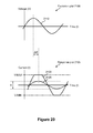
- the invention provides a method, which includes receiving an output voltage signal produced by a power supply, superimposing an excitation signal onto the output voltage signal to produce a superimposed signal, connecting the superimposed signal to an electrode in a droplet actuator, suppressing the output voltage signal when detecting an impedance of the electrode, and measuring the impedance of the electrode produced by the excitation signal, wherein the impedance indicates presence of liquid at the electrode.
- superimposing the excitation signal includes adding the excitation signal to the output voltage signal.
- suppressing the output voltage signal includes stopping the output voltage signal.
- suppressing the output voltage signal includes disabling a switching action of the power supply.
- suppressing the output voltage signal includes disabling the power supply.
- the method includes receiving a suppression signal to suppress the output voltage signal from the power supply. In certain embodiments the method includes determining a saturation of the impedance. In certain embodiments the method includes: injecting the liquid into the droplet actuator, and stopping injection when the impedance indicates the liquid has flowed to the electrode. In certain embodiments the method includes: injecting the liquid into a gap in the droplet actuator, and stopping injection when the impedance indicates the liquid has flowed to the electrode. In certain embodiments the method includes: injecting the liquid into a reservoir in the droplet actuator, and stopping injection when the impedance indicates the liquid has flowed to the electrode.
- the method includes: injecting the liquid to fill a reservoir in the droplet actuator, and stopping injection when the impedance indicates the liquid has flowed from the reservoir to the electrode.
- the method includes: establishing a fluid path in the droplet actuator from an input port to a reservoir to the electrode, injecting the liquid through the input port to fill the reservoir, and stopping injection when the impedance indicates the liquid has flowed to the electrode.
- the method includes: arranging an input port outside a boundary of a reservoir in the droplet actuator, forming a fluid path from the input port to the reservoir to the electrode, injecting the liquid through the input port to fill the reservoir, and stopping injection when the impedance indicates the liquid has flowed to the electrode.
- the method includes generating an output voltage by a power supply, storing charge produced by the output voltage, superimposing an excitation signal onto the output voltage to produce a superimposed signal, connecting the superimposed signal to an electrode in a droplet actuator, suppressing the output voltage from the power supply when detecting an impedance at the electrode, supplying the charge to the droplet actuator to activate the electrode during the impedance, and measuring the impedance produced by the excitation signal while the output voltage is suppressed, wherein the impedance indicates presence of liquid at the electrode.
- superimposing the excitation signal includes adding the excitation signal to the output voltage.
- suppressing the output voltage includes at least one of stopping the output voltage generated by the power supply, disabling a switching action of the power supply, and disabling the power supply during the impedance measurement.
- the invention includes activating a suppression signal to suppress the output voltage generated by the power supply.
- the method includes deactivating the suppression signal to resume the output voltage generated by the power supply.
- the method includes charging a capacitor to store the charge.
- the method includes determining whether the impedance is saturated.
- the method includes: injecting the liquid into the droplet actuator, and stopping injection when the impedance indicates the liquid has flowed to the electrode.
- the method includes: injecting the liquid into a gap in the droplet actuator, and stopping injection into the gap when the impedance indicates the liquid has flowed to the electrode. In certain embodiments the method includes: injecting the liquid into a reservoir in the droplet actuator, and stopping injection into the reservoir when the impedance indicates the liquid has flowed to the electrode. In certain embodiments the method includes: establishing a fluid path in the droplet actuator from an input port to a reservoir to the electrode, injecting the liquid through the input port to fill the reservoir, and stopping injection when the impedance indicates the liquid has flowed to the electrode.
- the method includes: arranging an input port outside a boundary of a reservoir in the droplet actuator, forming a fluid path from the input port to the reservoir to the electrode, injecting the liquid through the input port to fill the reservoir, and stopping injection when the impedance indicates the liquid has flowed to the electrode.
- the invention provides a system, comprising: a processor, memory, and code stored in the memory that when executed cause the processor at least to: receive an output voltage signal, superimpose an excitation signal onto the output voltage signal to produce a superimposed signal, connect the superimposed signal to an electrode in a droplet actuator, suppress the output voltage signal when detecting an impedance of the electrode, and measure the impedance of the electrode produced by the excitation signal, wherein the impedance indicates presence of liquid at the electrode.
- the code further causes the processor to at least one of add the excitation signal to the output voltage signal, stop the output voltage signal, disable a switching action of the power supply, and disable the power supply.
- the code further causes the processor to determine a saturation of the impedance.
- the code further causes the processor to: cause injection of the liquid into the droplet actuator, and stop the injection when the impedance indicates the liquid has flowed to the electrode. In some cases, the code further causes the processor to: cause injection of the liquid into a gap in the droplet actuator, and stop the injection when the impedance indicates the liquid has flowed to the electrode. In some cases, the code further causes the processor to: cause injection of the liquid into a reservoir in the droplet actuator, and stop the injection when the impedance indicates the liquid has flowed to the electrode. In some cases, the code further causes the processor to: cause the injection of the liquid to fill a reservoir in the droplet actuator, and stop the injection when the impedance indicates the liquid has flowed from the reservoir to the electrode.
- the code further causes the processor to: cause injection of the liquid into an input port of a reservoir in the droplet actuator, and stop the injection when the impedance indicates the liquid has flowed along a fluid path from the reservoir to the electrode.
- the code may be cause the operation of any of the methods of the invention.
- the invention provides a computer readable medium storing processor executable instructions for performing a method, the method comprising: generating an output voltage by a power supply, storing charge produced by the output voltage, superimposing an excitation signal onto the output voltage to produce a superimposed signal, connecting the superimposed signal to an electrode in a droplet actuator, suppressing the output voltage from the power supply when detecting an impedance at the electrode, supplying the charge to the droplet actuator to activate the electrode during the impedance, and measuring the impedance produced by the excitation signal while the output voltage is suppressed, wherein the impedance indicates presence of liquid at the electrode.
- the computer readable medium includes instructions for at least one of adding the excitation signal to the output voltage, stopping the output voltage generated by the power supply, disabling a switching action of the power supply, and disabling the power supply during the impedance measurement.
- the computer readable medium includes instructions for activating a suppression signal to suppress the output voltage generated by the power supply.
- the computer readable medium includes instructions for deactivating the suppression signal to resume the output voltage generated by the power supply.
- the computer readable medium includes instructions for charging a capacitor to store the charge.
- the computer readable medium includes instructions for determining the impedance is saturated.
- the computer readable medium includes instructions for: injecting the liquid into the droplet actuator, and stopping injection when the impedance indicates the liquid has flowed to the electrode. In some cases, the computer readable medium includes instructions for: injecting the liquid into a gap in the droplet actuator, and stopping injection into the gap when the impedance indicates the liquid has flowed to the electrode. In some cases, the computer readable medium includes instructions for: injecting the liquid into a reservoir in the droplet actuator, and stopping injection into the reservoir when the impedance indicates the liquid has flowed to the electrode. In some cases, the computer readable medium includes instructions for: injecting the liquid through an input port to fill a reservoir in the droplet actuator, stopping injection when the impedance indicates the liquid has flowed to the electrode. In some cases, the computer readable medium includes instructions for: injecting the liquid into an input port of a reservoir in the droplet actuator, and stopping injection when the impedance indicates the liquid has flowed along a fluid path from the reservoir to the electrode.
- Activate means affecting a change in the electrical state of the one or more electrodes which, in the presence of a droplet, results in a droplet operation.
- Activation of an electrode can be accomplished using alternating or direct current. Any suitable voltage may be used.
- an electrode may be activated using a voltage which is greater than about 150 V, or greater than about 200 V, or greater than about 250 V, or from about 275 V to about 375 V, or about 300 V. Where alternating current is used, any suitable frequency may be employed.
- an electrode may be activated using alternating current having a frequency from about 1 Hz to about 100 Hz, or from about 10 Hz to about 60 Hz, or from about 20 Hz to about 40 Hz, or about 30 Hz.
- alternating current having a frequency from about 1 Hz to about 100 Hz, or from about 10 Hz to about 60 Hz, or from about 20 Hz to about 40 Hz, or about 30 Hz.
- Droplet operations and other droplet control electrodes of the invention may be activated.
- Bead with respect to beads on a droplet actuator, means any bead or particle that is capable of interacting with a droplet on or in proximity with a droplet actuator.
- Beads may be any of a wide variety of shapes, such as spherical, generally spherical, egg shaped, disc shaped, cubical, amorphous and other three dimensional shapes.
- the bead may, for example, be capable of being subjected to a droplet operation in a droplet on a droplet actuator or otherwise configured with respect to a droplet actuator in a manner which permits a droplet on the droplet actuator to be brought into contact with the bead on the droplet actuator and/or off the droplet actuator.
- Beads may be provided in a droplet, in a droplet operations gap, or on a droplet operations surface. Beads may be provided in a reservoir that is external to a droplet operations gap or situated apart from a droplet operations surface, and the reservoir may be associated with a flow path that permits a droplet including the beads to be brought into a droplet operations gap or into contact with a droplet operations surface. Beads may be manufactured using a wide variety of materials, including for example, resins, and polymers. The beads may be any suitable size, including for example, microbeads, microparticles, nanobeads and nanoparticles. In some cases, beads are magnetically responsive; in other cases beads are not significantly magnetically responsive.
- the magnetically responsive material may constitute substantially all of a bead, a portion of a bead, or only one component of a bead.
- the remainder of the bead may include, among other things, polymeric material, coatings, and moieties which permit attachment of an assay reagent.
- suitable beads include flow cytometry microbeads, polystyrene microparticles and nanoparticles, functionalized polystyrene microparticles and nanoparticles, coated polystyrene microparticles and nanoparticles, silica microbeads, fluorescent microspheres and nanospheres, functionalized fluorescent microspheres and nanospheres, coated fluorescent microspheres and nanospheres, color dyed microparticles and nanoparticles, magnetic microparticles and nanoparticles, superparamagnetic microparticles and nanoparticles (e.g., DYNABEADS® particles, available from Invitrogen Group, Carlsbad, CA), fluorescent microparticles and nanoparticles, coated magnetic microparticles and nanoparticles, ferromagnetic microparticles and nanoparticles, coated ferromagnetic microparticles and nanoparticles, and those described in U.S.
- DYNABEADS® particles available from Invitrogen Group, Carlsbad,
- Patent Publication Nos. 20050260686 entitled “Multiplex flow assays preferably with magnetic particles as solid phase,” published on November 24, 2005; 20030132538 , entitled “Encapsulation of discrete quanta of fluorescent particles,” published on July 17, 2003; 20050118574 , entitled “Multiplexed Analysis of Clinical Specimens Apparatus and Method,” published on June 2, 2005; 20050277197 . Entitled “Microparticles with Multiple Fluorescent Signals and Methods of Using Same,” published on December 15, 2005; 20060159962 , entitled “Magnetic Microspheres for use in Fluorescence-based Applications,” published on July 20, 2006; the entire disclosures of which are incorporated herein by reference for their teaching concerning beads and magnetically responsive materials and beads.
- Beads may be pre-coupled with a biomolecule or other substance that is able to bind to and form a complex with a biomolecule. Beads may be pre-coupled with an antibody, protein or antigen, DNA/RNA probe or any other molecule with an affinity for a desired target.
- droplet actuator techniques for immobilizing magnetically responsive beads and/or non-magnetically responsive beads and/or conducting droplet operations protocols using beads are described in U.S. Patent Application No. 11/639,566 , entitled “Droplet-Based Particle Sorting," filed on December 15, 2006; U.S. Patent Application No. 61/039,183 , entitled “Multiplexing Bead Detection in a Single Droplet,” filed on March 25, 2008; U.S.
- Patent Application No. 61/047,789 entitled “Droplet Actuator Devices and Droplet Operations Using Beads," filed on April 25, 2008
- U.S. Patent Application No. 61/086,183 entitled “Droplet Actuator Devices and Methods for Manipulating Beads,” filed on August 5, 2008
- International Patent Application No. PCT/US2008/053545 entitled “Droplet Actuator Devices and Methods Employing Magnetic Beads," filed on February 11, 2008
- International Patent Application No. PCT/US2008/058018 entitled “Bead-based Multiplexed Analytical Methods and Instrumentation,” filed on March 24, 2008
- Droplet means a volume of liquid on a droplet actuator.
- a droplet is at least partially bounded by a filler fluid.
- a droplet may be completely surrounded by a filler fluid or may be bounded by filler fluid and one or more surfaces of the droplet actuator.
- a droplet may be bounded by filler fluid, one or more surfaces of the droplet actuator, and/or the atmosphere.
- a droplet may be bounded by filler fluid and the atmosphere.
- Droplets may, for example, be aqueous or non-aqueous or may be mixtures or emulsions including aqueous and non-aqueous components.
- Droplets may take a wide variety of shapes; nonlimiting examples include generally disc shaped, slug shaped, truncated sphere, ellipsoid, spherical, partially compressed sphere, hemispherical, ovoid, cylindrical, combinations of such shapes, and various shapes formed during droplet operations, such as merging or splitting or formed as a result of contact of such shapes with one or more surfaces of a droplet actuator.
- a droplet may include a biological sample, such as whole blood, lymphatic fluid, serum, plasma, sweat, tear, saliva, sputum, cerebrospinal fluid, amniotic fluid, seminal fluid, vaginal excretion, serous fluid, synovial fluid, pericardial fluid, peritoneal fluid, pleural fluid, transudates, exudates, cystic fluid, bile, urine, gastric fluid, intestinal fluid, fecal samples, liquids containing single or multiple cells, liquids containing organelles, fluidized tissues, fluidized organisms, liquids containing multi-celled organisms, biological swabs and biological washes.
- a biological sample such as whole blood, lymphatic fluid, serum, plasma, sweat, tear, saliva, sputum, cerebrospinal fluid, amniotic fluid, seminal fluid, vaginal excretion, serous fluid, synovial fluid, pericardial fluid, peritoneal fluid, pleural fluid, transudates, ex
- a droplet may include a reagent, such as water, deionized water, saline solutions, acidic solutions, basic solutions, detergent solutions and/or buffers.
- reagents such as a reagent for a biochemical protocol, such as a nucleic acid amplification protocol, an affinity-based assay protocol, an enzymatic assay protocol, a sequencing protocol, and/or a protocol for analyses of biological fluids.
- a droplet may include one or more beads.
- Droplet Actuator means a device for manipulating droplets.
- droplet actuators see Pamula et al., U.S. Patent 6,911,132 , entitled “Apparatus for Manipulating Droplets by Electrowetting-Based Techniques,” issued on June 28, 2005; Pamula et al., U.S. Patent Application No. 11/343,284 , entitled “Apparatuses and Methods for Manipulating Droplets on a Printed Circuit Board,” filed on filed on January 30, 2006; Pollack et al., International Patent Application No. PCT/US2006/047486 , entitled “Droplet-Based Biochemistry,” filed on December 11, 2006; Shenderov, U.S.
- Patents 6,773,566 entitled “Electrostatic Actuators for Microfluidics and Methods for Using Same,” issued on August 10, 2004 and 6,565,727 , entitled “Actuators for Microfluidics Without Moving Parts,” issued on January 24, 2000; Kim and/or Shah et al., U.S. Patent Application Nos.
- Patent 7,547,380 entitled “Droplet Transportation Devices and Methods Having a Fluid Surface,” issued on June 16, 2009; Sterling et al., U.S. Patent 7,163,612 , entitled “Method, Apparatus and Article for Microfluidic Control via Electrowetting, for Chemical, Biochemical and Biological Assays and the Like,” issued on January 16, 2007; Becker and Gascoyne et al., U.S. Patent Nos.
- Certain droplet actuators will include one or more substrates arranged with a droplet operations gap therebetween and electrodes associated with (e.g., layered on, attached to, and/or embedded in) the one or more substrates and arranged to conduct one or more droplet operations.
- certain droplet actuators will include a base (or bottom) substrate, droplet operations electrodes associated with the substrate, one or more dielectric layers atop the substrate and/or electrodes, and optionally one or more hydrophobic layers atop the substrate, dielectric layers and/or the electrodes forming a droplet operations surface.
- a top substrate may also be provided, which is separated from the droplet operations surface by a gap, commonly referred to as a droplet operations gap.
- Various electrode arrangements on the top and/or bottom substrates are discussed in the above-referenced patents and applications and certain novel electrode arrangements are discussed in the description of the invention.
- a ground or reference electrode may be associated with the top substrate facing the gap, the bottom substrate facing the gap, in the gap.
- electrical contacts for coupling the electrodes to a droplet actuator instrument for controlling or monitoring the electrodes may be associated with one or both plates.
- electrodes on one substrate are electrically coupled to the other substrate so that only one substrate is in contact with the droplet actuator.
- a conductive material e.g., an epoxy, such as MASTER BONDTM Polymer System EP79, available from Master Bond, Inc., Hackensack, NJ
- a conductive material provides the electrical connection between electrodes on one substrate and electrical paths on the other substrates, e.g., a ground electrode on a top substrate may be coupled to an electrical path on a bottom substrate by such a conductive material.
- a spacer may be provided between the substrates to determine the height of the gap therebetween and define dispensing reservoirs.
- the spacer height may, for example, be from about 5 ⁇ m to about 600 ⁇ m, or about 100 ⁇ m to about 400 ⁇ m, or about 200 ⁇ m to about 350 ⁇ m, or about 250 ⁇ m to about 300 ⁇ m, or about 275 ⁇ m.
- the spacer may, for example, be formed of a layer of projections form the top or bottom substrates, and/or a material inserted between the top and bottom substrates.
- One or more openings may be provided in the one or more substrates for forming a fluid path through which liquid may be delivered into the droplet operations gap.
- the one or more openings may in some cases be aligned for interaction with one or more electrodes, e.g., aligned such that liquid flowed through the opening will come into sufficient proximity with one or more droplet operations electrodes to permit a droplet operation to be effected by the droplet operations electrodes using the liquid.
- the one or more openings may in some cases serve as vents for releasing liquid or gas from within the droplet operations gap.
- the openings may be sealed or covered with a permeable material such as a membrane.
- a membrane having oleophobicity and hydrophobicity such as VERSAPOR® Membrane (Pall Corp., Port Washington, NY) may be used to cover an opening to facilitate escape of gasses while preventing escape of oil and aqueous liquids.
- the base (or bottom) and top substrates may in some cases be formed as one integral component, such as a folded or layered plastic or layered semiconductor construction.
- One or more reference electrodes may be provided on the base (or bottom) and/or top substrates and/or in the gap. Examples of reference electrode arrangements are provided in the above referenced patents and patent applications.
- the manipulation of droplets by a droplet actuator may be electrode mediated, e.g., electrowetting mediated or dielectrophoresis mediated or Coulombic force mediated.
- electrode mediated e.g., electrowetting mediated or dielectrophoresis mediated or Coulombic force mediated.
- other techniques for controlling droplet operations include using devices that induce hydrodynamic fluidic pressure, such as those that operate on the basis of mechanical principles (e.g. external syringe pumps, pneumatic membrane pumps, vibrating membrane pumps, vacuum devices, centrifugal forces, piezoelectric/ultrasonic pumps and acoustic forces); electrical or magnetic principles (e.g.
- thermodynamic principles e.g. gas bubble generation/phase-change-induced volume expansion
- other kinds of surface-wetting principles e.g. electrowetting, and optoelectrowetting, as well as chemically, thermally, structurally and radioactively induced surface-tension gradients
- gravity e.g., capillary action
- electrostatic forces e.g., electroosmotic flow
- centrifugal flow substrate disposed on a compact disc and rotated
- magnetic forces e.g., oscillating ions causes flow
- magnetohydrodynamic forces and vacuum or pressure differential.
- combinations of two or more of the foregoing techniques may be employed to conduct a droplet operation in a droplet actuator of the invention.
- one or more of the foregoing may be used to deliver liquid into a droplet operations gap, e.g., from a reservoir in another device or from an external reservoir of the droplet actuator (e.g., a reservoir associated with a droplet actuator substrate and a flow path from the reservoir into the droplet operations gap).
- Droplet operations surfaces of certain droplet actuators of the invention may be made from hydrophobic materials or may be coated or treated to make them hydrophobic.
- some portion or all of the droplet operations surfaces may be derivatized with low surface-energy materials or chemistries, e.g., by deposition or using in situ synthesis using compounds such as poly- or per-fluorinated compounds in solution or polymerizable monomers.
- the droplet operations surface may include a hydrophobic coating having a thickness ranging from about 10 nm to about 1,000 nm.
- the top substrate of the droplet actuator includes an electrically conducting organic polymer, which is then coated with a hydrophobic coating or otherwise treated to make the droplet operations surface hydrophobic.
- the electrically conducting organic polymer that is deposited onto a plastic substrate may be poly(3,4-ethylenedioxythiophene) poly(styrenesulfonate) (PEDOT:PSS).
- PDOT:PSS poly(3,4-ethylenedioxythiophene) poly(styrenesulfonate)
- Other examples of electrically conducting organic polymers and alternative conductive layers are described in Pollack et al., International Patent Application No. PCT/US2010/040705 , entitled “Droplet Actuator Devices and Methods," the entire disclosure of which is incorporated herein by reference.
- One or both substrates may be fabricated using a printed circuit board (PCB), glass, indium tin oxide (ITO)-coated glass, and/or semiconductor materials as the substrate.
- the ITO coating is preferably a thickness in the range of about 20 to about 200 nm, preferably about 50 to about 150 nm, or about 75 to about 125 nm, or about 100 nm.
- the top and/or bottom substrate includes a PCB substrate that is coated with a dielectric, such as a polyimide dielectric, which may in some cases also be coated or otherwise treated to make the droplet operations surface hydrophobic.
- the substrate includes a PCB
- suitable materials are examples of suitable materials: MITSUITM BN-300 (available from MITSUI Chemicals America, Inc., San Jose CA); ARLONTM 11N (available from Arlon, Inc, Santa Ana, CA).; NELCO® N4000-6 and N5000-30/32 (available from Park Electrochemical Corp., Melville, NY); ISOLATM FR406 (available from Isola Group, Chandler, AZ), especially IS620; fluoropolymer family (suitable for fluorescence detection since it has low background fluorescence); polyimide family; polyester; polyethylene naphthalate; polycarbonate; polyetheretherketone; liquid crystal polymer; cyclo-olefin copolymer (COC); cyclo-olefin polymer (COP); aramid; THERMOUNT® nonwoven aramid reinforcement (available from DuPont, Wilmington, DE); NOMEX® brand fiber (available from DuPont, Wilmington, DE); and paper.
- MITSUITM BN-300
- Various materials are also suitable for use as the dielectric component of the substrate. Examples include: vapor deposited dielectric, such as PARYLENETM C (especially on glass) and PARYLENETM N (available from Parylene Coating Services, Inc., Katy, TX); TEFLON® AF coatings; cytop; soldermasks, such as liquid photoimageable soldermasks (e.g., on PCB) like TAIYOTM PSR4000 series, TAIYOTM PSR and AUS series (available from Taiyo America, Inc.
- Droplet transport voltage and frequency may be selected for performance with reagents used in specific assay protocols.
- Design parameters may be varied, e.g., number and placement of on-actuator reservoirs, number of independent electrode connections, size (volume) of different reservoirs, placement of magnets/bead washing zones, electrode size, inter-electrode pitch, and gap height (between top and bottom substrates) may be varied for use with specific reagents, protocols, droplet volumes, etc.
- a substrate of the invention may derivatized with low surface-energy materials or chemistries, e.g., using deposition or in situ synthesis using poly- or per-fluorinated compounds in solution or polymerizable monomers.
- the droplet operations surface may be coated with a substance for reducing background noise, such as background fluorescence from a PCB substrate.
- the noise-reducing coating may include a black matrix resin, such as the black matrix resins available from Toray industries, Inc., Japan. Electrodes of a droplet actuator are typically controlled by a controller or a processor, which is itself provided as part of a system, which may include processing functions as well as data and software storage and input and output capabilities.
- Reagents may be provided on the droplet actuator in the droplet operations gap or in a reservoir fluidly coupled to the droplet operations gap.
- the reagents may be in liquid form, e.g., droplets, or they may be provided in a reconstitutable form in the droplet operations gap or in a reservoir fluidly coupled to the droplet operations gap.
- Reconstitutable reagents may typically be combined with liquids for reconstitution.
- An example of reconstitutable reagents suitable for use with the invention includes those described in Meathrel, et al., U.S. Patent 7,727,466 , entitled “Disintegratable films for diagnostic devices," granted on June 1, 2010.
- Droplet operation means any manipulation of a droplet on a droplet actuator.
- a droplet operation may, for example, include: loading a droplet into the droplet actuator; dispensing one or more droplets from a source droplet; splitting, separating or dividing a droplet into two or more droplets; transporting a droplet from one location to another in any direction; merging or combining two or more droplets into a single droplet; diluting a droplet; mixing a droplet; agitating a droplet; deforming a droplet; retaining a droplet in position; incubating a droplet; heating a droplet; vaporizing a droplet; cooling a droplet; disposing of a droplet; transporting a droplet out of a droplet actuator; other droplet operations described herein; and/or any combination of the foregoing.
- merge “merge,” “merging,” “combine,” “combining” and the like are used to describe the creation of one droplet from two or more droplets. It should be understood that when such a term is used in reference to two or more droplets, any combination of droplet operations that are sufficient to result in the combination of the two or more droplets into one droplet may be used. For example, “merging droplet A with droplet B,” can be achieved by transporting droplet A into contact with a stationary droplet B, transporting droplet B into contact with a stationary droplet A, or transporting droplets A and B into contact with each other.
- splitting is not intended to imply any particular outcome with respect to volume of the resulting droplets (i.e., the volume of the resulting droplets can be the same or different) or number of resulting droplets (the number of resulting droplets may be 2, 3, 4, 5 or more).
- mixing refers to droplet operations which result in more homogenous distribution of one or more components within a droplet. Examples of “loading” droplet operations include microdialysis loading, pressure assisted loading, robotic loading, passive loading, and pipette loading. Droplet operations may be electrode-mediated. In some cases, droplet operations are further facilitated by the use of hydrophilic and/or hydrophobic regions on surfaces and/or by physical obstacles.
- Impedance or capacitance sensing or imaging techniques may sometimes be used to determine or confirm the outcome of a droplet operation. Examples of such techniques are described in Sturmer et al., International Patent Pub. No. WO/2008/101194 , entitled “Capacitance Detection in a Droplet Actuator,” published on August 21, 2008, the entire disclosure of which is incorporated herein by reference. Generally speaking, the sensing or imaging techniques may be used to confirm the presence or absence of a droplet at a specific electrode.
- the presence of a dispensed droplet at the destination electrode following a droplet dispensing operation confirms that the droplet dispensing operation was effective.
- the presence of a droplet at a detection spot at an appropriate step in an assay protocol may confirm that a previous set of droplet operations has successfully produced a droplet for detection.
- Droplet transport time can be quite fast. For example, in various embodiments, transport of a droplet from one electrode to the next may exceed about 1 sec, or about 0.1 sec, or about 0.01 sec, or about 0.001 sec.
- the electrode is operated in AC mode but is switched to DC mode for imaging.
- 1x-, 2x-3x-droplets are usefully controlled operated using 1, 2, and 3 electrodes, respectively. If the droplet footprint is greater than the number of electrodes available for conducting a droplet operation at a given time, the difference between the droplet size and the number of electrodes should typically not be greater than 1; in other words, a 2x droplet is usefully controlled using 1 electrode and a 3x droplet is usefully controlled using 2 electrodes.
- droplets include beads, it is useful for droplet size to be equal to the number of electrodes controlling the droplet, e.g., transporting the droplet.
- Filler fluid means a fluid associated with a droplet operations substrate of a droplet actuator, which fluid is sufficiently immiscible with a droplet phase to render the droplet phase subject to electrode-mediated droplet operations.
- the droplet operations gap of a droplet actuator is typically filled with a filler fluid.
- the filler fluid may, for example, be a low-viscosity oil, such as silicone oil or hexadecane filler fluid.
- the filler fluid may fill the entire gap of the droplet actuator or may coat one or more surfaces of the droplet actuator.
- Filler fluids may be conductive or non-conductive. Filler fluids may, for example, be doped with surfactants or other additives.
- additives may be selected to improve droplet operations and/or reduce loss of reagent or target substances from droplets, formation of microdroplets, cross contamination between droplets, contamination of droplet actuator surfaces, degradation of droplet actuator materials, etc.
- Composition of the filler fluid, including surfactant doping may be selected for performance with reagents used in the specific assay protocols and effective interaction or non-interaction with droplet actuator materials. Examples of filler fluids and filler fluid formulations suitable for use with the invention are provided in Srinivasan et al, International Patent Pub. Nos.
- WO/2010/027894 entitled “Droplet Actuators, Modified Fluids and Methods,” published on March 11, 2010, and WO/2009/021173 , entitled “Use of Additives for Enhancing Droplet Operations,” published on February 12, 2009; Sista et al., International Patent Pub. No. WO/2008/098236 , entitled “Droplet Actuator Devices and Methods Employing Magnetic Beads,” published on August 14, 2008; and Monroe et al., U.S. Patent Publication No. 20080283414 , entitled “Electrowetting Devices,” filed on May 17, 2007; the entire disclosures of which are incorporated herein by reference, as well as the other patents and patent applications cited herein.
- Immobilize with respect to magnetically responsive beads, means that the beads are substantially restrained in position in a droplet or in filler fluid on a droplet actuator.
- immobilized beads are sufficiently restrained in position in a droplet to permit execution of a droplet splitting operation, yielding one droplet with substantially all of the beads and one droplet substantially lacking in the beads.
- Magnetically responsive means responsive to a magnetic field.
- Magnetically responsive beads include or are composed of magnetically responsive materials. Examples of magnetically responsive materials include paramagnetic materials, ferromagnetic materials, ferrimagnetic materials, and metamagnetic materials. Examples of suitable paramagnetic materials include iron, nickel, and cobalt, as well as metal oxides, such as Fe3O4, BaFe12O19, CoO, NiO, Mn2O3, Cr2O3, and CoMnP.
- a droplet actuator system of the invention may include on-cartridge reservoirs and/or off-cartridge reservoirs.
- On-cartridge reservoirs may be (1) on-actuator reservoirs, which are reservoirs in the droplet operations gap or on the droplet operations surface; (2) off-actuator reservoirs, which are reservoirs on the droplet actuator cartridge, but outside the droplet operations gap, and not in contact with the droplet operations surface; or (3) hybrid reservoirs which have on-actuator regions and off-actuator regions.
- An example of an off-actuator reservoir is a reservoir in the top substrate.
- An off-actuator reservoir is typically in fluid communication with an opening or flow path arranged for flowing liquid from the off-actuator reservoir into the droplet operations gap, such as into an on-actuator reservoir.
- An off-cartridge reservoir may be a reservoir that is not part of the droplet actuator cartridge at all, but which flows liquid to some portion of the droplet actuator cartridge.
- an off-cartridge reservoir may be part of a system or docking station to which the droplet actuator cartridge is coupled during operation.
- an off-cartridge reservoir may be a reagent storage container or syringe which is used to force fluid into an on-cartridge reservoir or into a droplet operations gap.
- a system using an off-cartridge reservoir will typically include a fluid passage means whereby liquid may be transferred from the off-cartridge reservoir into an on-cartridge reservoir or into a droplet operations gap.
- Transporting into the magnetic field of a magnet is intended to refer to transporting into a region of a magnetic field capable of substantially attracting magnetically responsive beads in the droplet.
- transporting away from a magnet or magnetic field is intended to refer to transporting away from a region of a magnetic field capable of substantially attracting magnetically responsive beads in the droplet, whether or not the droplet or magnetically responsive beads is completely removed from the magnetic field.
- the droplet may be transported towards or away from the desired region of the magnetic field, and/or the desired region of the magnetic field may be moved towards or away from the droplet.
- Reference to an electrode, a droplet, or magnetically responsive beads being "within” or “in” a magnetic field, or the like, is intended to describe a situation in which the electrode is situated in a manner which permits the electrode to transport a droplet into and/or away from a desired region of a magnetic field, or the droplet or magnetically responsive beads is/are situated in a desired region of the magnetic field, in each case where the magnetic field in the desired region is capable of substantially attracting any magnetically responsive beads in the droplet.
- a droplet, or magnetically responsive beads being "outside of” or “away from” a magnetic field, and the like, is intended to describe a situation in which the electrode is situated in a manner which permits the electrode to transport a droplet away from a certain region of a magnetic field, or the droplet or magnetically responsive beads is/are situated away from a certain region of the magnetic field, in each case where the magnetic field in such region is not capable of substantially attracting any magnetically responsive beads in the droplet or in which any remaining attraction does not eliminate the effectiveness of droplet operations conducted in the region.
- a system, a droplet actuator, or another component of a system may include a magnet, such as one or more permanent magnets (e.g., a single cylindrical or bar magnet or an array of such magnets, such as a Halbach array) or an electromagnet or array of electromagnets, to form a magnetic field for interacting with magnetically responsive beads or other components on chip.
- a magnet such as one or more permanent magnets (e.g., a single cylindrical or bar magnet or an array of such magnets, such as a Halbach array) or an electromagnet or array of electromagnets, to form a magnetic field for interacting with magnetically responsive beads or other components on chip.
- Such interactions may, for example, include substantially immobilizing or restraining movement or flow of magnetically responsive beads during storage or in a droplet during a droplet operation or pulling magnetically responsive beads out of a droplet.
- Washing with respect to washing a bead means reducing the amount and/or concentration of one or more substances in contact with the bead or exposed to the bead from a droplet in contact with the bead.
- the reduction in the amount and/or concentration of the substance may be partial, substantially complete, or even complete.
- the substance may be any of a wide variety of substances; examples include target substances for further analysis, and unwanted substances, such as components of a sample, contaminants, and/or excess reagent.
- a washing operation begins with a starting droplet in contact with a magnetically responsive bead, where the droplet includes an initial amount and initial concentration of a substance. The washing operation may proceed using a variety of droplet operations.
- the washing operation may yield a droplet including the magnetically responsive bead, where the droplet has a total amount and/or concentration of the substance which is less than the initial amount and/or concentration of the substance.
- suitable washing techniques are described in Pamula et al., U.S. Patent 7,439,014 , entitled “Droplet-Based Surface Modification and Washing,” granted on October 21, 2008, the entire disclosure of which is incorporated herein by reference.
- top bottom
- over under
- under on
- the terms “top,” “bottom,” “over,” “under,” and “on” are used throughout the description with reference to the relative positions of components of the droplet actuator, such as relative positions of top and bottom substrates of the droplet actuator. It will be appreciated that the droplet actuator is functional regardless of its orientation in space.
- a liquid in any form e.g., a droplet or a continuous body, whether moving or stationary
- a liquid in any form e.g., a droplet or a continuous body, whether moving or stationary
- an electrode, array, matrix or surface such liquid could be either in direct contact with the electrode/array/matrix/surface, or could be in contact with one or more layers or films that are interposed between the liquid and the electrode/array/matrix/surface.
- a droplet When a droplet is described as being “on” or “loaded on” a droplet actuator, it should be understood that the droplet is arranged on the droplet actuator in a manner which facilitates using the droplet actuator to conduct one or more droplet operations on the droplet, the droplet is arranged on the droplet actuator in a manner which facilitates sensing of a property of or a signal from the droplet, and/or the droplet has been subjected to a droplet operation on the droplet actuator.
- the present invention is microfluidic feedback methods using impedance detection with respect to electrodes of droplet actuators.
- the microfluidic feedback methods of the invention may correlate impedance measurements to the presence or absence of liquid at certain electrodes of a droplet actuator, such as at certain droplet operations electrodes and/or certain reservoir electrodes.
- impedance detection operations may be used to verify and/or monitor the presence or absence of liquid at a certain electrode in a droplet actuator.
- certain actions may be taken in the protocol that is executing on the droplet actuator based on the presence or absence of liquid at a certain electrode, as determined using impedance detection according to the present invention.
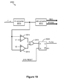
- the impedance sensing circuit provides a mechanism for reducing, preferably entirely eliminating, noise on the reference voltage power supply during impedance detection operations.
- the impedance sensing circuit provides a mechanism for flagging a saturation condition with respect to the response signal.
- Digital microfluidic technology conducts droplet operations on discrete droplets by electrical control of their surface tension (electrowetting).
- the droplets may be sandwiched between two substrates, a bottom substrate and a top substrate separated by a gap.
- the bottom substrate may, for example, be a printed circuit board (PCB) with an arrangement of electrically addressable electrodes.
- the top substrate may, for example, be an injection molded plastic top substrate with a reference electrode plane made, for example, from conductive ink or indium-tin oxide (ITO).
- ITO indium-tin oxide
- the bottom substrate and the top substrate may be coated with a hydrophobic material.
- the space around the droplets may be filled with an immiscible inert fluid, such as silicone oil, to prevent evaporation of the droplets and to facilitate their transport within the device.
- an electric field formed when voltage is applied to a control electrode on the bottom substrate, reduces the interfacial tension between the droplet and the electrode. This effect may be used to transport droplets using surface energy gradients established by activating a pattern of control electrodes on the bottom substrate along any path of contiguous electrodes.
- Other droplet operations may be effected by varying the patterns of voltage activation; examples include merging, splitting, mixing, and dispensing of droplets.
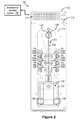
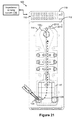
- Figure 1 illustrates an exploded view of an example of a droplet actuator 100 that may be used to provide microfluidic feedback using impedance detection.
- droplet actuator 100 is configured for integrated sample preparation and nucleic acid testing of a single sample.
- Droplet actuator 100 may include a bottom substrate 110 and a top substrate 112.
- a gasket 114 may be sandwiched between bottom substrate 110 and top substrate 112.
- bottom substrate 110 may be a PCB that has an electrode arrangement 116 and a set of power/signal input/output (I/O) pads 118 patterned thereon.
- Electrode arrangement 116 may include, for example, reservoir electrodes 120a through 120f that are associated with reservoirs R1 through R6, respectively.
- Electrode arrangement 116 may also include a sample reservoir electrode 122 that is associated with a sample reservoir R7. Reservoir electrodes 120a through 120f and sample reservoir electrode 122 are arranged in relation to a path, line, and/or array of droplet operations electrodes 124 (e.g., electrowetting electrodes).
- Sample reservoir electrode 122 may be segmented into an arrangement of multiple individually controlled electrodes, which is shown with reference to Figures 2 and 3 . Droplet operations are conducted atop these various electrodes on a droplet operations surface. More details of electrode arrangement 116 are described with reference to Figures 2 , 3 , 4A, and 4B .
- Top substrate 112 may be formed of a material that is substantially transparent to visible light, ultraviolet (UV) light, and/or any wavelength light of interest.
- top substrate 112 may be formed of glass, injection-molded plastic, and/or silicon. Additionally, top substrate 112 may be coated with ITO, thereby providing an electrical ground plane.
- a clearance region is provided in gasket 114.
- the clearance region of gasket 114 forms a gap between bottom substrate 110 and top substrate 112 at the droplet operations surface.
- the thickness of gasket 114 may be used to set the height of the gap.
- the shape of the clearance region of gasket 114 substantially corresponds to the shape of electrode arrangement 116 of bottom substrate 110.
- the shape of the clearance region of gasket 114 at reservoir electrodes 120a through 120f and at sample reservoir electrode 122, together with bottom substrate 110 and top substrate 112 form reservoirs R1 through R6 and sample reservoir R7. Reservoirs R1 through R6 and sample reservoir R7 are examples of on-actuator reservoirs.
- Reservoirs R1 through R6 may be, for example, reagent reservoirs for holding/dispensing various reagent fluids, such as, but not limited to, elution buffer solution and wash buffer solution.
- Respective input ports 134 e.g., input ports 134a through 134f of reservoirs R1 through R6 may be integrated into top substrate 112.
- Sample reservoir R7 may be provided for preparing and dispensing sample fluids.
- Sample reservoir R7 may be of sufficient size to contain a large volume of fluid, e.g., about 1.5 mL.
- One or more input ports of sample reservoir R7 may be integrated into top substrate 112.
- an input port 128 for loading sample fluids into sample reservoir R7 may be integrated into top substrate 112.
- an input port 130 for loading sample preparation reagents (e.g., lysis buffer, nucleic acid capture beads) into sample reservoir R7 may be integrated into top substrate 112.
- Top substrate 112 may include certain features (not shown) for helping define the volume of the on-actuator reservoirs (e.g., reservoirs R1 through R6 and sample reservoir R7).
- top substrate 112 When bottom substrate 110, top substrate 112, and gasket 114 are assembled together, input port 128 and input port 130 in top substrate 112 are substantially aligned with at least a portion of sample reservoir electrode 122 of bottom substrate 110. Similarly, input ports 134 in top substrate 112 are substantially aligned with at least a portion of their respective reservoir electrodes 120 of bottom substrate 110. More details of droplet actuator 100 are described with reference to Figures 2 through 5H .
- a port (e.g., input port 128, input port 130, and input ports 134) is an entrance/exit (opening) to the droplet operations gap. Liquid may flow through the port into any portion of the gap. That could be into a reservoir region of the gap or onto a droplet operations pathway. A port may be used to fill the gap with filler fluid. However, in most cases, a reagent fluid or sample fluid flowing through a port should come into sufficient proximity with an electrode, such that the electrode can be used to conduct one or more droplet operations using the liquid, such as droplet transport, splitting, and dispensing.
- the gap height at sample reservoir R7 may be greater than the gap height at reservoirs R1 through R6 and/or along unit-sized droplet operations electrodes 124.
- the gap height at sample reservoir R7 may be about > 3mm to facilitate storage of larger liquid volumes (e.g., about 1.5 mL) and ready dispensing of droplets.
- the gap height at reservoirs R1 through R6 and/or along droplet operations electrodes 124 may be about 250-500 ⁇ m in order to facilitate, for example, rapid transport, mixing, washing, and/or incubation of one or more droplets.
- the gap height transition region may be at the dispensing end of sample reservoir R7, which is the portion of sample reservoir R7 that feeds the line of droplet operations electrodes 124.
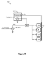
- An imaging system 150 may be used in combination with droplet actuator 100.
- a detection electrode 135 is provided at the end of the line of droplet operations electrodes 124 that is opposite sample reservoir R7. Accordingly, a detection window 136 may be included in top substrate 112 at detection electrode 135. Imaging system 150 uses detection window 136 for performing detection operations on any droplet atop detection electrode 135. The amount of transparency provided at detection window 136 may vary.
- Detection window 136 may be formed to direct and/or filter light, e.g., formed as a lens and/or as an optical filter that excludes certain wavelengths. Light energy that is generated in the gap of droplet actuator 100 may be transmitted through detection window 136 and then captured by imaging system 150.
- imaging system 150 may include one or more light-emitting diodes (LEDs) 152 (i.e., an illumination source) and a digital image capture device, such as a charge-coupled device (CCD) camera 154.
- LEDs light-emitting diodes
- CCD charge-coupled device
- imaging system 150 may include one or more light-emitting diodes (LEDs) 152 (i.e., an illumination source) and a digital image capture device, such as a charge-coupled device (CCD) camera 154.
- CCD charge-coupled device
- Figure 2 illustrates a top down view of droplet actuator 100 when its components are fully assembled. More specifically, Figure 2 shows bottom substrate 110, top substrate 112, and gasket 114 assembled together to form droplet actuator 100. Figure 2 shows that the clearance region of gasket 114 substantially corresponds to the shape of electrode arrangement 116 of bottom substrate 110. Additionally, the alignment is shown of sample reservoir R7 to sample reservoir electrode 122 of bottom substrate 110. Similarly, the alignment is shown of reservoirs R1 through R6 to their respective reservoir electrodes 120 of bottom substrate 110. I/O pads 118 are contacts that are connected by wiring traces to the electrodes, such as to reservoir electrodes 120, sample reservoir electrode 122, and droplet operations electrodes 124. In one example, I/O pads 118 are used for applying electrowetting voltages.
- I/O pads 118 are coupled to a controller, which includes the circuitry for detecting impedance at a specific electrode.
- a controller which includes the circuitry for detecting impedance at a specific electrode.
- One I/O pad 118 may be coupled to top substrate 112 to provide the return path for the circuit.
- Figure 2 also shows an impedance sensing system 170, which is one example of circuitry for detecting impedance at a specific electrode. Impedance sensing system 170 may be, for example, an impedance spectrometer.
- Impedance sensing system 170 may be used to monitor the capacitive loading of any electrode with or without liquid thereon.
- capacitance detection techniques see Sturmer et al., International Patent Publication No. WO/2008/101194 , entitled “Capacitance Detection in a Droplet Actuator,” published on Aug. 21, 2008; and Kale et al., International Patent Publication No. WO/2002/080822 , entitled “System and Method for Dispensing Liquids,” published on Oct. 17, 2002; the entire disclosures of which are incorporated herein by reference.
- impedance sensing system 170 may be used to capture an impedance measurement between any electrode of bottom substrate 110 and the ground reference electrode of top substrate 112.
- impedance sensing system 170 may be used to scan the reservoir electrodes 120, sample reservoir electrode 122, and droplet operations electrodes 124.
- An impedance measurement may be stored for each individual electrode of droplet actuator 100.
- the microfluidic feedback methods of the invention may use impedance measurements taken by impedance sensing system 170 to determine the presence or absence of liquid at certain electrodes of droplet actuator 100, such as at certain reservoir electrodes 120, sample reservoir electrode 122, and certain droplet operations electrodes 124.
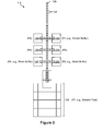
- FIG 3 illustrates atop view of electrode arrangement 116 of droplet actuator 100 of Figure 1 .
- electrode arrangement 116 includes reservoir electrodes 120a through 120f and sample reservoir electrode 122, which are arranged in relation to the droplet operations electrodes 124.
- reservoir R1 at reservoir electrode 120a may be filled with elution buffer solution
- reservoir R3 at reservoir electrode 120c may be filled with wash buffer solution
- reservoir R3 at reservoir electrode 120f may be also filled with wash buffer solution
- sample reservoir R7 at sample reservoir electrode 122 may be filled with sample fluid.
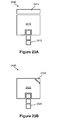
- FIGS 4A and 4B illustrate top views of a portion of electrode arrangement 116 of droplet actuator 100 of Figure 1 and show more details of reservoir electrodes 120a through 120f of reservoirs R1 through R6, respectively.
- Each of the reservoirs R1 through R6 may have three electrodes in the path leading to the line of droplet operations electrodes 124.
- at the dispensing side of each of the reservoirs R1 through R6 may be two dispensing electrodes 160 followed by a gate electrode 162.
- Gate electrode 162 is nearest the droplet operations electrodes 124.
- Figure 4A shows a volume of fluid 164 atop, for example, reservoir electrode 120a of reservoir R1.
- the fluid 164 is positioned substantially within the boundaries of reservoir electrode 120a.
- any reservoir electrode there is a risk of the fluid drifting toward the line of droplet operations electrodes 124, as shown in Figure 4B . If the droplet operations electrode 124 near, for example, gate electrode 162 of reservoir R1 happens to be activated, there is a risk of some of this fluid merging with other droplets (not shown) moving along the path of droplet operations electrodes 124.
- a microfluidics feedback mechanism such as impedance measurements taken of dispensing electrodes 160 and gate electrode 162 of reservoir R1, may be useful to monitor the position of fluid 164 in reservoir R1. If it is detected that that fluid 164 is drifting toward droplet operations electrodes 124, fluid 164 can be pulled back into the reservoir by, for example, activating reservoir electrode 120a of reservoir R1. In this way, any chance of fluid 164 in reservoir R1 interfering with other droplets moving along droplet operations electrodes 124 may be reduced, preferably entirely eliminated.
- An example of using impedance detection to monitor and/or verify the presence or absence of fluid on, for example, certain electrodes of droplet actuator 100 is described with reference to Figures 5A through 17 .
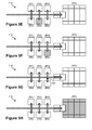
- Figures 5A through 5H illustrate top views of electrode arrangement 116 of droplet actuator 100 of Figure 1 and an example of an electrode activation sequence of certain impedance detection operations.
- the electrode activation sequence and impedance detection operations of Figures 5A through 5H is one example of a microfluidics feedback mechanism in a droplet actuator.
- reservoir electrode 120a of reservoir R1 and reservoir electrode 120b of reservoir R2 are activated and an impedance measurement is taken of reservoir electrode 120a and reservoir electrode 120b (together) using, for example, impedance sensing system 170 of Figure 2 .
- reservoir electrode 120c of reservoir R3 is activated and an impedance measurement is taken of reservoir electrode 120c using impedance sensing system 170 of Figure 2 .
- gate electrode 162 of reservoir R3 is activated and an impedance measurement is taken of this gate electrode 162 using impedance sensing system 170 of Figure 2 .
- reservoir electrode 120d of reservoir R4 is activated and an impedance measurement is taken of reservoir electrode 120d using impedance sensing system 170 of Figure 2 .
- reservoir electrode 120e of reservoir R5 is activated and an impedance measurement is taken of reservoir electrode 120e using impedance sensing system 170 of Figure 2 .
- reservoir electrode 120f of reservoir R6 is activated and an impedance measurement is taken of reservoir electrode 120f using impedance sensing system 170 of Figure 2 .
- gate electrode 162 of reservoir R6 is activated and an impedance measurement is taken of this gate electrode 162 using impedance sensing system 170 of Figure 2 .
- sample reservoir electrode 122 of sample reservoir R7 is activated and an impedance measurement is taken of sample reservoir electrode 122 using impedance sensing system 170 of Figure 2 .
- Figures 6 through 16 illustrate graphs of examples of impedance measurements taken of certain electrodes of droplet actuator 100 of Figure 1 and under the various conditions and with the electrode activation shown in Figures 5A through 5H .
- a set of impedance measurements were taken of certain electrodes of droplet actuator 100 with filler oil only at the electrodes of interest.
- another set of impedance measurements were taken of certain electrodes of droplet actuator 100 with fluid at the electrodes.
- the graphs shown in Figures 6 through 16 are provided to show the contrast between the impedance measurements taken under the two different conditions, thereby demonstrating the use of impedance detection operations as a suitable microfluidic feedback mechanism for determining the presence or absence of fluid at any electrode of interest.
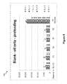
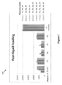
- a bar graph 700 shows the impedance measurements acquired with filler oil only in the gap of droplet actuator 100. That is, the gap of droplet actuator 100 is loaded with filler oil and this set of impedance measurements is acquired prior to loading droplet actuator 100 with any other fluids. Therefore, bar graph 700 shows pre-liquid loading impedance values at certain reservoirs of droplet actuator 100.
- the set of impedance readings shown in bar graph 700 may be referred to as the "blank values.” By way of example, multiple detection operations (or runs) were performed and plotted in bar graph 700.
- Runs 1 through 7 seven detection operations (runs 1 through 7) were performed and recorded with respect to reservoir R1 and reservoir R2 (see Figure 5A ), reservoir R3 (see Figure 5B ), reservoir R4 (see Figure 5D ), reservoir R5 (see Figure 5E ), reservoir R6 (see Figure 5F ), and sample reservoir R7 (see Figure 5H ) of droplet actuator 100.
- Run 5 is not shown due to technical problem during the run.
- Runs 1 through 7 may be the results of detection operations performed on one or more instances of droplet actuator 100.
- the impedance values in bar graph 700 and in subsequent bar graphs and plots are given in ohms.
- Bar graph 700 shows some variation in the blank values of sample reservoir R7.
- an air bubble is intentionally left in sample reservoir R7.
- a variation in the position of this bubble from one run to the next may contribute to the variation in the blank values.
- the presence of the two openings in top substrate 112 at sample reservoir R7 i.e., input ports 128 and 130 may contribute to the variation in the blank values of sample reservoir R7.
- Figure 7 shows a bar graph 800 that shows the impedance measurements acquired with fluid present at certain reservoirs of droplet actuator 100. That is, bar graph 800 shows post-liquid loading impedance values at certain reservoirs of droplet actuator 100.
- bar graph 800 shows a plot of another set of seven detection operations (runs 1 through 7). In runs 1, 2, and 3, reservoir R3, reservoir R6, and sample reservoir R7 are loaded with a certain amount of fluid. In runs 4, 5, 6, and 7, reservoir R1, reservoir R3, reservoir R6, and sample reservoir R7 are loaded with a certain amount of fluid.
- Reservoir R3, reservoir R6, and sample reservoir R7 are used in all runs, while reservoir R1 is only used in runs 4 through 7.
- the impedance values at reservoir R3 and reservoir R6, which are used in all runs, are consistent across runs.
- the impedance value at sample reservoir R7 is consistent across runs, unlike the blank values of sample reservoir R7 shown in bar graph 700 of Figure 6 .
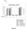
- a bar graph 900 shows a plot of the liquid loading delta Z values. That is, bar graph 900 shows the difference (called delta Z) between the pre-liquid loading impedance values of bar graph 700 of Figure 6 and the post-liquid loading impedance values of bar graph 800 of Figure 7 . Bar graph 900 indicates noticeable delta Z values between reservoirs that are loaded with fluid and reservoirs that are not loaded, which shows clear separation between loaded and empty reservoirs.
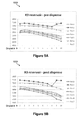
- a plot 1000 of the pre-dispense impedance values at reservoir R3 is shown with respect to 10 droplets. That is, 10 droplets are dispensed from reservoir R3 of droplet actuator 100 and an impedance measurement is taken on reservoir electrode 120c of reservoir R3 just prior to the dispensing of each droplet.
- a plot 1050 of the post-dispense impedance values at reservoir R3 is shown with respect to the same 10 droplets. That is, when the 10 droplets are dispensed from reservoir R3 of droplet actuator 100, an impedance measurement is taken on reservoir electrode 120c of reservoir R3 just after the dispensing of each droplet.
- seven runs of pre-dispense impedance values and post-dispense impedance values are collected. The seven runs may include one or more instances of droplet actuator 100.
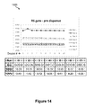
- a plot 1100 of the pre-dispense impedance values at gate electrode 162 of reservoir R3 is shown with respect to 10 droplets. That is, 10 droplets are dispensed from reservoir R3 of droplet actuator 100. As each droplet passes atop the gate electrode 162 of reservoir R3 an impedance measurement is acquired.
- Figure 10 also shows a table that includes for each of the seven runs (1) the average pre-dispense impedance value of the 10 droplets, (2) the standard deviation, and (3) the percent capacitance-voltage (CV%).
- FIG. 11 a plot 1200 of the post-dispense impedance values at gate electrode 162 of reservoir R3 is shown with respect to the same 10 droplets. That is, 10 droplets are dispensed from reservoir R3 of droplet actuator 100. As each of the 10 droplets is transported off of the gate electrode 162 of reservoir R3 an impedance measurement is acquired.
- Figure 11 also shows a table that includes for each of the seven runs (1) the average post-dispense impedance value of the 10 droplets, (2) the standard deviation, and (3) the CV%.
- a bar graph 1300 shows a plot of the delta Z values of gate electrode 162 of reservoir R3. That is, bar graph 1300 shows the difference (called delta Z) between the pre-dispense impedance values of bar graph 1100 of Figure 10 and the post-dispense impedance values of bar graph 1200 of Figure 11 .
- Figure 12 also shows a table that includes for each of the seven runs (1) the average delta Z value, (2) the standard deviation of the delta Z values, and (3) the CV% of the delta Z values. Additionally, the table shows the average delta Z value of all runs, the standard deviation of the delta Z value of all runs, and the CV% of the delta Z value of all runs.
- a plot 1400 of the pre-dispense impedance values at reservoir R6 is shown with respect to 10 droplets. That is, 10 droplets are dispensed from reservoir R6 of droplet actuator 100 and an impedance measurement is taken on reservoir electrode 120f of reservoir R6 just prior to the dispensing of each droplet.
- a plot 1450 of the post-dispense impedance values at reservoir R6 is shown with respect to the same 10 droplets. That is, when the 10 droplets are dispensed from reservoir R6 of droplet actuator 100, an impedance measurement is taken on reservoir electrode 120f of reservoir R6 just after the dispensing of each droplet.
- seven runs of pre-dispense impedance values and post-dispense impedance values are collected. The seven runs may include one or more instances of droplet actuator 100.
- a plot 1500 of the pre-dispense impedance values at gate electrode 162 of reservoir R6 is shown with respect to 10 droplets. That is, 10 droplets are dispensed from reservoir R6 of droplet actuator 100. As each droplet passes atop the gate electrode 162 of reservoir R6 an impedance measurement is acquired.
- Figure 14 also shows a table that includes for each of the seven runs (1) the average pre-dispense impedance value of the 10 droplets, (2) the standard deviation, and (3) the CV%.
- FIG. 15 a plot 1600 of the post-dispense impedance values at gate electrode 162 of reservoir R6 is shown with respect to the same 10 droplets. That is, 10 droplets are dispensed from reservoir R6 of droplet actuator 100. As each of the 10 droplets is transported off of the gate electrode 162 of reservoir R6 an impedance measurement is acquired.
- Figure 15 also shows a table that includes for each of the seven runs (1) the average post-dispense impedance value of the 10 droplets, (2) the standard deviation, and (3) the CV%.
- a bar graph 1700 shows a plot of the delta Z values of gate electrode 162 of reservoir R6. That is, bar graph 1700 shows the difference (called delta Z) between the pre-dispense impedance values of plot 1500 of Figure 14 and the post-dispense impedance values of plot 1600 of Figure 15 .
- Figure 16 also shows a table that includes for each of the seven runs (1) the average delta Z value, (2) the standard deviation of the delta Z values, and (3) the CV% of the delta Z values. Additionally, the table shows the average delta Z value of all runs, the standard deviation of the delta Z value of all runs, and the CV% of the delta Z value of all runs.
- temperature and/or droplet size may have an effect on the impedance measurements.
- the impedance sensing circuit that is used with a droplet actuator may utilize an impedance signal that is superimposed on a reference voltage.
- the reference voltage source is typically a switching power supply, which is a high voltage AC power supply for providing the electrowetting voltage (e.g., about 300 volts) to the electrodes of a droplet actuator.
- the stability of the high voltage AC power supply is critical because it is used as the impedance reference measurement voltage.
- switching power supplies may be noisy. For example, in a droplet actuator application, a ripple voltage of about 1 to about 3 volts may be present on the about 300V output.
- the impedance sensing circuit of the present invention provides a novel approach that does not rely on a voltage regulator to ensure stability of the high voltage AC power supply during impedance detection operations.
- the impedance sensing circuit includes an electrowetting voltage suppression mechanism for reducing noise during impedance detection operations, which is described with reference to Figures 17 and 18 .
- FIG 17 illustrates a schematic diagram of an example of an impedance sensing circuit 1800 of a droplet actuator that includes an electrowetting voltage suppression mechanism for reducing noise.
- Impedance sensing circuit 1800 may include a power supply (PS) 1810.
- PS 1810 provides the electrowetting voltage source that is needed to perform droplet operations.
- PS 1810 is a 300VAC power supply.
- Impedance sensing circuit 1800 may also include an impedance sensing system 1812.
- Impedance sensing system 1812 includes an excitation portion for generating an excitation signal and a detection portion for processing the return signal.
- the excitation signal of impedance sensing system 1812 is superimposed on the output of PS 1810 via, for example, a voltage adder 1814.
- the output of voltage adder 1814 may be selectively connected to any electrode of a droplet actuator.
- Figure 17 shows the output of voltage adder 1814 selectively connected to any reservoir electrode 120, sample reservoir electrode 122, and/or any droplet operations electrode 124 of droplet actuator 100 of Figures 1 , 2 , and 3 .
- the return path (with respect to the electrodes) to the detection portion of impedance sensing system 1812 is the electrical ground plane of the top substrate, such as top substrate 112 of droplet actuator 100.
- An aspect of the impedance sensing circuit 1800 of the invention is that it also includes a mechanism for suppressing the output of PS 1810 during impedance detection operations, thereby reducing, preferably entirely eliminating, noise on the output of PS 1810. In this way, the accuracy and/or reliability of impedance measurements taken by impedance sensing system 1812 may be improved.
- the switching action of PS 1810 which is the source of the noise, is suppressed (i.e., stopped) during impedance detection operations.
- Impedance sensing circuit 1800 includes a SUPPRESS signal that feeds the control of PS 1810 for disabling the switching action thereof during impedance detection operations. More details of the suppression mechanism of the invention are described with reference to Figure 18 .
- FIG 18 illustrates a schematic diagram showing more details of impedance sensing circuit 1800 of Figure 17 that includes the electrowetting voltage suppression mechanism.
- PS 1810 includes a direct current (DC) power source 1820, a transformer T1, and a switching circuit 1822.
- DC power source 1820 and switching circuit 1822 are arranged in relation to the primary of transformer T1.
- Switching circuit 1822 may include any solid state switch device, such as an NMOS switch. In one example, the solid state switch device may be toggled off and on by a square wave from an oscillator (not shown). Switching circuit 1822 is used to develop a low voltage AC signal at the primary of transformer T1.
- a standard rectifier circuit at the secondary of transformer T1 provides an output voltage (VAC) that is a higher voltage than the input voltage.
- PS 1810 also includes a tank capacitor C1 at VAC (i.e., at the secondary of transformer T1).
- a feedback loop is provided from VAC back to switching circuit 1822.
- the SUPPRESS signal feeds switching circuit 1822 of PS 1810. For example, when the SUPPRESS signal is active the switching action of the solid state switch device of PS 1810 is stopped. In one example, during impedance detection operations, the SUPPRESS signal is used to stop the switching action of PS 1810 for several milliseconds while the impedance measurements are taking place. Stopping the switching action reduces, preferably entirely eliminates, any noise (i.e., voltage ripple) on the output of PS 1810. At the same time, tank capacitor C1 stores the charge at the output of PS 1810. In this way, the output voltage of PS 1810 is maintained while the switching action of PS 1810 is being suppressed via the SUPPRESS signal. Once impedance measurements are complete, the SUPPRESS signal may be deactivated and the normal operation of PS 1810 resumes.
- the SUPPRESS signal may be deactivated and the normal operation of PS 1810 resumes.
- An example of a method of using impedance sensing circuit 1800 of the invention may include, but is not limited to, the following steps - (1) activate the SUPPRESS signal and, thereby, stop the switching action of PS 1810; (2) activate the excitation portion of impedance sensing system 1812 and, thereby, generate an excitation signal to any one or more electrodes of interest; (3) process the return signal(s) using the detection portion of impedance sensing system 1812; (4) correlate the impedance measurements to the presence and/or absence of fluid at the one or more electrodes of interest; (5) deactivate the excitation portion of impedance sensing system 1812; and (6) deactivate the SUPPRESS signal and, thereby, resume normal operation of PS 1810.
- FIG 19 illustrates a schematic diagram of a detection circuit 2000 of an impedance sensing system that includes a feature for logging a saturation condition of the response signal.
- detection circuit 2000 may be the detection portion of impedance sensing system 1812 of Figure 17 .
- Detection circuit 2000 may include, for example, a current-to-voltage (I/V) converter 2010 and an analog-to-digital (A/D) converter 2012.
- I/V converter 2010 e.g., an operational amplifier (op amp) arrangement
- op amp operational amplifier
- A/D converter 2012 converts the voltage level to digital data and, in particular, to MAGNITUDE and PHASE data to be processed.
- Figure 20 illustrates an example of an excitation plot 2100 in relation to a response plot 2105 of an impedance sensing system. Further, response plot 2105 of Figure 20 shows both a response non-saturation condition and a response saturation condition.
- Excitation plot 2100 of Figure 20 shows a plot of the excitation signal voltage vs. time.
- excitation plot 2100 shows a plot of an excitation signal 2110, which is, for example, a sign wave that has a certain frequency and amplitude.
- Response plot 2105 of Figure 20 shows a plot of the response signal current vs. time.
- response plot 2105 shows a plot of a response signal 2120, which is, for example, a sign wave that has a certain frequency and amplitude.
- Response signal 2120 is an example of a signal at the input of I/V converter 2010.
- A/D converter 2012 One output of A/D converter 2012 is the relative phase ( ⁇ ), which is the difference in phase between, for example, excitation signal 2110 of excitation plot 2100 and response signal 2120 of response plot 2105. Referring to Figure 19 , this may be called PHASE data.
- Another output of A/D converter 2012 is peak-to-peak amplitude of, for example, response signal 2120 of response plot 2105. Referring to Figure 19 , this may be called MAGNITUDE data.
- response signal 2120 of response plot 2105 is an example of a response signal that is in a non-saturation condition.
- response plot 2105 also shows a plot of a response signal 2122, which is an example of a response signal that is in a saturation condition with respect to I/V converter 2010.
- a V-MAX and a V-MIN voltage is associated with I/V converter 2010. Any response signal, such as response signal 2122, reaching and/or exceeding the V-MAX and/or V-MIN thresholds is in saturation (e.g., response signal 2122 shown flattened out at V-MAX and V-MIN).
- detection circuit 2000 includes a feature for logging a saturation condition of the response signal during any impedance detection operation.
- the output of I/V converter 2010 feeds a pair of comparators.
- the output of I/V converter 2010 is connected to the positive input of a comparator 2014 and to the negative input of a comparator 2016.
- a voltage V1 is provided at the negative input of comparator 2014.
- a voltage V2 is provided at the positive input of comparator 2016.
- V1 may be set just slightly above V-MIN and V2 may be set just slightly below V-MAX (see response plot 2105 of Figure 20 ).
- the outputs of comparator 2014 and comparator 2016 feed an OR gate 2018.
- the output of OR gate 2018 feeds a latch 2020.
- the output of latch 2020 provides a saturation FLAG signal. If the response signal (e.g., response signal 2122 of response plot 2105 of Figure 20 ) exceeds V1 or V2, the output of at least one of comparator 2014 and comparator 2016 transitions to a logic high. This causes the output of OR gate 2018 to also go high and sets latch 2020, which means the FLAG signal is active indicating that a saturation condition is present.
- latch 2020 may be reset. However, at the end of any impedance detection operation, the state of the FLAG signal is read to determine whether a saturation condition occurred. In this way, the impedance detection operation does not depend on the digital MAGNITUDE and PHASE data alone to determine whether a saturation condition has occurred.
- Figure 21 illustrates a top down view of droplet actuator 100 of Figure 1 that further includes an oil sensing electrode.
- An impedance detection operation of the oil sensing electrode may be used to verify that the gap of the droplet actuator is fully filled with filler oil.
- patterned on the end of bottom substrate 110 that is nearest detection electrode 135 is an oil sensing electrode 2210.
- a fluid path 2212 that leads to oil sensing electrode 2210 is provided in gasket 114. In this way a small on-actuator fluid reservoir is created at oil sensing electrode 2210.
- filler oil may be injected into the end of droplet actuator 100 that is opposite oil sensing electrode 2210. Therefore, oil sensing electrode 2210 is the last location to fill with oil.
- oil sensing electrode 2210 may be monitored for the presence of oil thereon.
- filler oil may be injected into the gap of droplet actuator 100 using input port 128 and/or input port 130 of sample reservoir R7. The filler oil then flows in the direction from sample reservoir R7 to oil sensing electrode 2210 in order to fill the active area of droplet actuator 100.
- oil sensing electrode 2210 is monitored using, for example, impedance sensing system 170.
- an oil sensing electrode such as oil sensing electrode 2210, provides a way to use impedance detection to ensure that the active area of droplet actuator 100 is fully filled with oil, according to the present invention.
- Figure 22 illustrates a top view of a portion of a droplet actuator 2300 in which the input port of an on-actuator reservoir is not directly over any portion of the reservoir electrode.
- droplet actuator 2300 includes a reservoir electrode 2310 that has a loading port 2312 in the top substrate (not shown) that is not directly over any portion of reservoir electrode 2310.
- a reservoir boundary 2314 is shown that defines the size, shape, and/or volume of the on-actuator reservoir.
- the reservoir boundary 2314 may be established by, for example, a gasket, features in the top substrate, features in the bottom substrate, and/or any combinations thereof.
- a fluid path 2316 is present from loading port 2312 to reservoir electrode 2310.
- loading port 2312 is not directly over reservoir electrode 2310 and fluid path 2316 is provided by which fluid may flow to the reservoir electrode 2310 for filling. In this way, the variability of the fluid volume at the reservoir may be reduced, preferably entirely eliminated, as indicated by less impedance measurement variability during filling and/or use.
- FIGS 23A and 23B illustrate top views of an electrode arrangement 2400 and an electrode arrangement 2420, respectively, which are examples of electrode configurations for helping to detect whether a sample reservoir is fully loaded.
- This invention provides a separate electrode at the fringe of the primary storage reservoir for measuring impedance in order to verify that the reservoir is fully loaded (i.e., not underloaded).
- electrode arrangement 2400 of Figure 23A includes a reservoir electrode 2410.
- Reservoir electrode 2410 may be associated with an on-actuator reservoir.
- One side of reservoir electrode 2410 feeds a line, path, and/or array of droplet operations electrodes 2412 (e.g., electrowetting electrodes).
- An elongated impedance electrode 2414 is provided along the side of reservoir electrode 2410 that is opposite the droplet operations electrodes 2412.
- the impedance electrode 2414 is a separate electrode at the fringe of the primary storage reservoir. Using impedance detection, one may verify that liquid is atop impedance electrode 2414, which provides assurance that the associated reservoir is fully loaded.
- electrode arrangement 2420 of Figure 23B includes a reservoir electrode 2422.
- Reservoir electrode 2422 may be associated with an on-actuator reservoir.
- One side of reservoir electrode 2422 feeds a line, path, and/or array of droplet operations electrodes 2424 (e.g., electrowetting electrodes).
- a triangular-shaped impedance electrode 2426 is provided at one of the corners of reservoir electrode 2422 that is opposite the droplet operations electrodes 2424.
- the impedance electrode 2426 is a separate electrode at the fringe of the primary storage reservoir. Using impedance detection, one may verify that liquid is atop impedance electrode 2426, which provides assurance that the associated reservoir is fully loaded. While Figures 23A and 23B describe examples of a single impedance electrode at one location with respect to the primary storage reservoir, Figures 24A, 24B, and 24C describe examples of impedance electrodes at multiple locations of the primary storage reservoir.
- Figures 24A, 24B, and 24C illustrate top views of an electrode arrangement 2500, an electrode arrangement 2520, and an electrode arrangement 2540, respectively, which are more examples of electrode configurations for helping to detect whether a sample reservoir is fully loaded.
- electrode arrangement 2500 of Figure 24A includes a reservoir electrode 2510.
- Reservoir electrode 2510 may be associated with an on-actuator reservoir.
- One side of reservoir electrode 2510 feeds a line, path, and/or array of droplet operations electrodes 2512 (e.g., electrowetting electrodes).
- a U-shaped impedance electrode 2514 is provided along the three sides of reservoir electrode 2510 that do not feed droplet operations electrodes 2512. Again, the impedance electrode 2514 is a separate electrode at the fringe of the primary storage reservoir. Using impedance detection, one may verify that liquid is atop impedance electrode 2514, which provides assurance that the associated reservoir is fully loaded.
- electrode arrangement 2520 of Figure 24B includes a reservoir electrode 2522.
- Reservoir electrode 2522 may be associated with an on-actuator reservoir.
- One side of reservoir electrode 2510 feeds a line, path, and/or array of droplet operations electrodes 2524 (e.g., electrowetting electrodes).
- Reservoir electrode 2522 is flanked by two elongated impedance electrodes 2526 (e.g., impedance electrodes 2526a and 2525b). Again, impedance electrodes 2526a and 2525b are separate electrodes at the fringe of the primary storage reservoir. Using impedance detection, one may verify that liquid is atop impedance electrodes 2526a and 2525b, which provides assurance that the associated reservoir is fully loaded.
- electrode arrangement 2540 of Figure 24C includes a reservoir electrode 2542.
- Reservoir electrode 2542 may be associated with an on-actuator reservoir.
- One side of reservoir electrode 2542 feeds a line, path, and/or array of droplet operations electrodes 2544 (e.g., electrowetting electrodes).
- four triangular-shaped impedance electrodes 2546 e.g., impedance electrodes 2546a, 2546b, 2546c, and 2546d
- impedance electrodes 2546a, 2546b, 2546c, and 2546d are separate electrodes at the fringe of the primary storage reservoir.
- impedance detection one may verify that liquid is atop impedance electrodes 2546a, 2546b, 2546c, and 2546d, which provides assurance that the associated reservoir is fully loaded.
- aspects of the invention may be embodied as a method, system, computer readable medium, and/or computer program product.
- aspects of the invention may take the form of hardware embodiments, software embodiments (including firmware, resident software, micro-code, etc.), or embodiments combining software and hardware aspects that may all generally be referred to herein as a "circuit,” “module” or “system.”
- the methods of the invention may take the form of a computer program product on a computer-usable storage medium having computer-usable program code embodied in the medium.
- the computer-usable or computer-readable medium may be, for example but not limited to, an electronic, magnetic, optical, electromagnetic, infrared, or semiconductor system, apparatus, device, or propagation medium.
- the computer readable medium may include transitory and/or non-transitory embodiments.
- the computer-readable medium would include some or all of the following: an electrical connection having one or more wires, a portable computer diskette, a hard disk, a random access memory (RAM), a read-only memory (ROM), an erasable programmable read-only memory (EPROM or Flash memory), an optical fiber, a portable compact disc read-only memory (CD-ROM), an optical storage device, a transmission medium such as those supporting the Internet or an intranet, or a magnetic storage device.
- RAM random access memory
- ROM read-only memory
- EPROM or Flash memory erasable programmable read-only memory
- CD-ROM compact disc read-only memory
- CD-ROM compact disc read-only memory
- a transmission medium such as those supporting the Internet or an intranet, or a magnetic storage device.
- the computer-usable or computer-readable medium could even be paper or another suitable medium upon which the program is printed, as the program can be electronically captured, via, for instance, optical scanning of the paper or other medium, then compiled, interpreted, or otherwise processed in a suitable manner, if necessary, and then stored in a computer memory.
- a computer-usable or computer-readable medium may be any medium that can contain, store, communicate, propagate, or transport the program for use by or in connection with the instruction execution system, apparatus, or device.
- Program code for carrying out operations of the invention may be written in an object oriented programming language such as Java, Smalltalk, C++ or the like. However, the program code for carrying out operations of the invention may also be written in conventional procedural programming languages, such as the "C" programming language or similar programming languages.
- the program code may be executed by a processor, application specific integrated circuit (ASIC), or other component that executes the program code.
- the program code may be simply referred to as a software application that is stored in memory (such as the computer readable medium discussed above).
- the program code may cause the processor (or any processor-controlled device) to produce a graphical user interface ("GUI").
- GUI graphical user interface
- the graphical user interface may be visually produced on a display device, yet the graphical user interface may also have audible features.
- the program code may operate in any processor-controlled device, such as a computer, server, personal digital assistant, phone, television, or any processor-controlled device utilizing the processor and/or a digital signal processor.
- the program code may locally and/or remotely execute.
- the program code for example, may be entirely or partially stored in local memory of the processor-controlled device.
- the program code may also be at least partially remotely stored, accessed, and downloaded to the processor-controlled device.
- a user's computer for example, may entirely execute the program code or only partly execute the program code.
- the program code may be a stand-alone software package that is at least partly on the user's computer and/or partly executed on a remote computer or entirely on a remote computer or server. In the latter scenario, the remote computer may be connected to the user's computer through a communications network.
- the invention may be applied regardless of networking environment.
- the communications network may be a cable network operating in the radio-frequency domain and/or the Internet Protocol (IP) domain.
- IP Internet Protocol
- the communications network may also include a distributed computing network, such as the Internet (sometimes alternatively known as the "World Wide Web"), an intranet, a local-area network (LAN), and/or a wide-area network (WAN).
- the communications network may include coaxial cables, copper wires, fiber optic lines, and/or hybrid-coaxial lines.
- the communications network may even include wireless portions utilizing any portion of the electromagnetic spectrum and any signaling standard (such as the IEEE 802 family of standards, GSM/CDMA/TDMA or any cellular standard, and/or the ISM band).
- the communications network may even include powerline portions, in which signals are communicated via electrical wiring.
- the invention may be applied to any wireless/wireline communications network, regardless of physical componentry, physical configuration, or communications standard(s).
- the program code may also be stored in a computer-readable memory that can direct the processor, computer, or other programmable data processing apparatus to function in a particular manner, such that the program code stored in the computer-readable memory produce or transform an article of manufacture including instruction means which implement various aspects of the method steps.
- the program code may also be loaded onto a computer or other programmable data processing apparatus to cause a series of operational steps to be performed to produce a processor/computer implemented process such that the program code provides steps for implementing various functions/acts specified in the methods of the invention.
Abstract
Description
- This patent application is related to and claims priority to
U.S. Provisional Patent Application No. 61/483,827, filed on May 9, 2011 - A droplet actuator typically includes one or more substrates configured to form a surface or gap for conducting droplet operations. The one or more substrates establish a droplet operations surface or gap for conducting droplet operations and may also include electrodes arrange to conduct the droplet operations. The droplet operations substrate or the gap between the substrates may be coated or filled with a filler fluid that is immiscible with the liquid that forms the droplets. It may be beneficial to determine and/or verify the presence or absence of liquid at certain electrodes of a droplet actuator, such as at droplet operations electrodes and reservoir electrodes. Therefore, there is a need for methods of microfluidic feedback in droplet actuators.
- In one embodiment, the invention provides a method, which includes receiving an output voltage signal produced by a power supply, superimposing an excitation signal onto the output voltage signal to produce a superimposed signal, connecting the superimposed signal to an electrode in a droplet actuator, suppressing the output voltage signal when detecting an impedance of the electrode, and measuring the impedance of the electrode produced by the excitation signal, wherein the impedance indicates presence of liquid at the electrode. In some cases, superimposing the excitation signal includes adding the excitation signal to the output voltage signal. In certain embodiments suppressing the output voltage signal includes stopping the output voltage signal. In certain embodiments suppressing the output voltage signal includes disabling a switching action of the power supply. In certain embodiments suppressing the output voltage signal includes disabling the power supply. In certain embodiments the method includes receiving a suppression signal to suppress the output voltage signal from the power supply. In certain embodiments the method includes determining a saturation of the impedance. In certain embodiments the method includes: injecting the liquid into the droplet actuator, and stopping injection when the impedance indicates the liquid has flowed to the electrode. In certain embodiments the method includes: injecting the liquid into a gap in the droplet actuator, and stopping injection when the impedance indicates the liquid has flowed to the electrode. In certain embodiments the method includes: injecting the liquid into a reservoir in the droplet actuator, and stopping injection when the impedance indicates the liquid has flowed to the electrode. In certain embodiments the method includes: injecting the liquid to fill a reservoir in the droplet actuator, and stopping injection when the impedance indicates the liquid has flowed from the reservoir to the electrode. In certain embodiments the method includes: establishing a fluid path in the droplet actuator from an input port to a reservoir to the electrode, injecting the liquid through the input port to fill the reservoir, and stopping injection when the impedance indicates the liquid has flowed to the electrode. In certain embodiments the method includes: arranging an input port outside a boundary of a reservoir in the droplet actuator, forming a fluid path from the input port to the reservoir to the electrode, injecting the liquid through the input port to fill the reservoir, and stopping injection when the impedance indicates the liquid has flowed to the electrode. In another embodiment, the method includes generating an output voltage by a power supply, storing charge produced by the output voltage, superimposing an excitation signal onto the output voltage to produce a superimposed signal, connecting the superimposed signal to an electrode in a droplet actuator, suppressing the output voltage from the power supply when detecting an impedance at the electrode, supplying the charge to the droplet actuator to activate the electrode during the impedance, and measuring the impedance produced by the excitation signal while the output voltage is suppressed, wherein the impedance indicates presence of liquid at the electrode. In certain embodiments superimposing the excitation signal includes adding the excitation signal to the output voltage. In certain embodiments suppressing the output voltage includes at least one of stopping the output voltage generated by the power supply, disabling a switching action of the power supply, and disabling the power supply during the impedance measurement. In certain embodiments the invention includes activating a suppression signal to suppress the output voltage generated by the power supply. In certain embodiments the method includes deactivating the suppression signal to resume the output voltage generated by the power supply. In certain embodiments the method includes charging a capacitor to store the charge. In certain embodiments the method includes determining whether the impedance is saturated. In certain embodiments the method includes: injecting the liquid into the droplet actuator, and stopping injection when the impedance indicates the liquid has flowed to the electrode. In certain embodiments the method includes: injecting the liquid into a gap in the droplet actuator, and stopping injection into the gap when the impedance indicates the liquid has flowed to the electrode. In certain embodiments the method includes: injecting the liquid into a reservoir in the droplet actuator, and stopping injection into the reservoir when the impedance indicates the liquid has flowed to the electrode. In certain embodiments the method includes: establishing a fluid path in the droplet actuator from an input port to a reservoir to the electrode, injecting the liquid through the input port to fill the reservoir, and stopping injection when the impedance indicates the liquid has flowed to the electrode. In certain embodiments the method includes: arranging an input port outside a boundary of a reservoir in the droplet actuator, forming a fluid path from the input port to the reservoir to the electrode, injecting the liquid through the input port to fill the reservoir, and stopping injection when the impedance indicates the liquid has flowed to the electrode.
- In another embodiment, the invention provides a system, comprising: a processor, memory, and code stored in the memory that when executed cause the processor at least to: receive an output voltage signal, superimpose an excitation signal onto the output voltage signal to produce a superimposed signal, connect the superimposed signal to an electrode in a droplet actuator, suppress the output voltage signal when detecting an impedance of the electrode, and measure the impedance of the electrode produced by the excitation signal, wherein the impedance indicates presence of liquid at the electrode. In some cases, the code further causes the processor to at least one of add the excitation signal to the output voltage signal, stop the output voltage signal, disable a switching action of the power supply, and disable the power supply. In some cases, the code further causes the processor to determine a saturation of the impedance. In some cases, the code further causes the processor to: cause injection of the liquid into the droplet actuator, and stop the injection when the impedance indicates the liquid has flowed to the electrode. In some cases, the code further causes the processor to: cause injection of the liquid into a gap in the droplet actuator, and stop the injection when the impedance indicates the liquid has flowed to the electrode. In some cases, the code further causes the processor to: cause injection of the liquid into a reservoir in the droplet actuator, and stop the injection when the impedance indicates the liquid has flowed to the electrode. In some cases, the code further causes the processor to: cause the injection of the liquid to fill a reservoir in the droplet actuator, and stop the injection when the impedance indicates the liquid has flowed from the reservoir to the electrode. In some cases, the code further causes the processor to: cause injection of the liquid into an input port of a reservoir in the droplet actuator, and stop the injection when the impedance indicates the liquid has flowed along a fluid path from the reservoir to the electrode. The code may be cause the operation of any of the methods of the invention.
- The invention provides a computer readable medium storing processor executable instructions for performing a method, the method comprising: generating an output voltage by a power supply, storing charge produced by the output voltage, superimposing an excitation signal onto the output voltage to produce a superimposed signal, connecting the superimposed signal to an electrode in a droplet actuator, suppressing the output voltage from the power supply when detecting an impedance at the electrode, supplying the charge to the droplet actuator to activate the electrode during the impedance, and measuring the impedance produced by the excitation signal while the output voltage is suppressed, wherein the impedance indicates presence of liquid at the electrode. In some cases, the computer readable medium includes instructions for at least one of adding the excitation signal to the output voltage, stopping the output voltage generated by the power supply, disabling a switching action of the power supply, and disabling the power supply during the impedance measurement. In some cases, the computer readable medium includes instructions for activating a suppression signal to suppress the output voltage generated by the power supply. In some cases, the computer readable medium includes instructions for deactivating the suppression signal to resume the output voltage generated by the power supply. In some cases, the computer readable medium includes instructions for charging a capacitor to store the charge. In some cases, the computer readable medium includes instructions for determining the impedance is saturated. In some cases, the computer readable medium includes instructions for: injecting the liquid into the droplet actuator, and stopping injection when the impedance indicates the liquid has flowed to the electrode. In some cases, the computer readable medium includes instructions for: injecting the liquid into a gap in the droplet actuator, and stopping injection into the gap when the impedance indicates the liquid has flowed to the electrode. In some cases, the computer readable medium includes instructions for: injecting the liquid into a reservoir in the droplet actuator, and stopping injection into the reservoir when the impedance indicates the liquid has flowed to the electrode. In some cases, the computer readable medium includes instructions for: injecting the liquid through an input port to fill a reservoir in the droplet actuator, stopping injection when the impedance indicates the liquid has flowed to the electrode. In some cases, the computer readable medium includes instructions for: injecting the liquid into an input port of a reservoir in the droplet actuator, and stopping injection when the impedance indicates the liquid has flowed along a fluid path from the reservoir to the electrode.
- As used herein, the following terms have the meanings indicated.
- "Activate," with reference to one or more electrodes, means affecting a change in the electrical state of the one or more electrodes which, in the presence of a droplet, results in a droplet operation. Activation of an electrode can be accomplished using alternating or direct current. Any suitable voltage may be used. For example, an electrode may be activated using a voltage which is greater than about 150 V, or greater than about 200 V, or greater than about 250 V, or from about 275 V to about 375 V, or about 300 V. Where alternating current is used, any suitable frequency may be employed. For example, an electrode may be activated using alternating current having a frequency from about 1 Hz to about 100 Hz, or from about 10 Hz to about 60 Hz, or from about 20 Hz to about 40 Hz, or about 30 Hz. Droplet operations and other droplet control electrodes of the invention may be activated.
- "Bead," with respect to beads on a droplet actuator, means any bead or particle that is capable of interacting with a droplet on or in proximity with a droplet actuator. Beads may be any of a wide variety of shapes, such as spherical, generally spherical, egg shaped, disc shaped, cubical, amorphous and other three dimensional shapes. The bead may, for example, be capable of being subjected to a droplet operation in a droplet on a droplet actuator or otherwise configured with respect to a droplet actuator in a manner which permits a droplet on the droplet actuator to be brought into contact with the bead on the droplet actuator and/or off the droplet actuator. Beads may be provided in a droplet, in a droplet operations gap, or on a droplet operations surface. Beads may be provided in a reservoir that is external to a droplet operations gap or situated apart from a droplet operations surface, and the reservoir may be associated with a flow path that permits a droplet including the beads to be brought into a droplet operations gap or into contact with a droplet operations surface. Beads may be manufactured using a wide variety of materials, including for example, resins, and polymers. The beads may be any suitable size, including for example, microbeads, microparticles, nanobeads and nanoparticles. In some cases, beads are magnetically responsive; in other cases beads are not significantly magnetically responsive. For magnetically responsive beads, the magnetically responsive material may constitute substantially all of a bead, a portion of a bead, or only one component of a bead. The remainder of the bead may include, among other things, polymeric material, coatings, and moieties which permit attachment of an assay reagent. Examples of suitable beads include flow cytometry microbeads, polystyrene microparticles and nanoparticles, functionalized polystyrene microparticles and nanoparticles, coated polystyrene microparticles and nanoparticles, silica microbeads, fluorescent microspheres and nanospheres, functionalized fluorescent microspheres and nanospheres, coated fluorescent microspheres and nanospheres, color dyed microparticles and nanoparticles, magnetic microparticles and nanoparticles, superparamagnetic microparticles and nanoparticles (e.g., DYNABEADS® particles, available from Invitrogen Group, Carlsbad, CA), fluorescent microparticles and nanoparticles, coated magnetic microparticles and nanoparticles, ferromagnetic microparticles and nanoparticles, coated ferromagnetic microparticles and nanoparticles, and those described in
U.S. Patent Publication Nos. 20050260686 , entitled "Multiplex flow assays preferably with magnetic particles as solid phase," published on November 24, 2005;20030132538 , entitled "Encapsulation of discrete quanta of fluorescent particles," published on July 17, 2003;20050118574 , entitled "Multiplexed Analysis of Clinical Specimens Apparatus and Method," published on June 2, 2005;20050277197 . Entitled "Microparticles with Multiple Fluorescent Signals and Methods of Using Same," published on December 15, 2005;20060159962 , entitled "Magnetic Microspheres for use in Fluorescence-based Applications," published on July 20, 2006; the entire disclosures of which are incorporated herein by reference for their teaching concerning beads and magnetically responsive materials and beads. Beads may be pre-coupled with a biomolecule or other substance that is able to bind to and form a complex with a biomolecule. Beads may be pre-coupled with an antibody, protein or antigen, DNA/RNA probe or any other molecule with an affinity for a desired target. Examples of droplet actuator techniques for immobilizing magnetically responsive beads and/or non-magnetically responsive beads and/or conducting droplet operations protocols using beads are described inU.S. Patent Application No. 11/639,566 U.S. Patent Application No. 61/039,183 U.S. Patent Application No. 61/047,789 U.S. Patent Application No. 61/086,183 PCT/US2008/053545 , entitled "Droplet Actuator Devices and Methods Employing Magnetic Beads," filed on February 11, 2008; International Patent Application No.PCT/US2008/058018 , entitled "Bead-based Multiplexed Analytical Methods and Instrumentation," filed on March 24, 2008; International Patent Application No.PCT/US2008/058047 , "Bead Sorting on a Droplet Actuator," filed on March 23, 2008; and International Patent Application No.PCT/US2006/047486 , entitled "Droplet-based Biochemistry," filed on December 11, 2006; the entire disclosures of which are incorporated herein by reference. Bead characteristics may be employed in the multiplexing aspects of the invention. Examples of beads having characteristics suitable for multiplexing, as well as methods of detecting and analyzing signals emitted from such beads, may be found inU.S. Patent Publication No. 20080305481 , entitled "Systems and Methods for Multiplex Analysis of PCR in Real Time," published on December 11, 2008;U.S. Patent Publication No. 20080151240 , "Methods and Systems for Dynamic Range Expansion," published on June 26, 2008;U.S. Patent Publication No. 20070207513 , entitled "Methods, Products, and Kits for Identifying an Analyte in a Sample," published on September 6, 2007;U.S. Patent Publication No. 20070064990 , entitled "Methods and Systems for Image Data Processing," published on March 22, 2007;U.S. Patent Publication No. 20060159962 , entitled "Magnetic Microspheres for use in Fluorescence-based Applications," published on July 20, 2006;U.S. Patent Publication No. 20050277197 , entitled "Microparticles with Multiple Fluorescent Signals and Methods of Using Same," published on December 15, 2005; andU.S. Patent Publication No. 20050118574 , entitled "Multiplexed Analysis of Clinical Specimens Apparatus and Method," published on June 2, 2005. "Droplet" means a volume of liquid on a droplet actuator. Typically, a droplet is at least partially bounded by a filler fluid. For example, a droplet may be completely surrounded by a filler fluid or may be bounded by filler fluid and one or more surfaces of the droplet actuator. As another example, a droplet may be bounded by filler fluid, one or more surfaces of the droplet actuator, and/or the atmosphere. As yet another example, a droplet may be bounded by filler fluid and the atmosphere. Droplets may, for example, be aqueous or non-aqueous or may be mixtures or emulsions including aqueous and non-aqueous components. Droplets may take a wide variety of shapes; nonlimiting examples include generally disc shaped, slug shaped, truncated sphere, ellipsoid, spherical, partially compressed sphere, hemispherical, ovoid, cylindrical, combinations of such shapes, and various shapes formed during droplet operations, such as merging or splitting or formed as a result of contact of such shapes with one or more surfaces of a droplet actuator. For examples of droplet fluids that may be subjected to droplet operations using the approach of the invention, see International Patent Application No.PCT/US 06/47486 , entitled, "Droplet-Based Biochemistry," filed on December 11, 2006. In various embodiments, a droplet may include a biological sample, such as whole blood, lymphatic fluid, serum, plasma, sweat, tear, saliva, sputum, cerebrospinal fluid, amniotic fluid, seminal fluid, vaginal excretion, serous fluid, synovial fluid, pericardial fluid, peritoneal fluid, pleural fluid, transudates, exudates, cystic fluid, bile, urine, gastric fluid, intestinal fluid, fecal samples, liquids containing single or multiple cells, liquids containing organelles, fluidized tissues, fluidized organisms, liquids containing multi-celled organisms, biological swabs and biological washes. Moreover, a droplet may include a reagent, such as water, deionized water, saline solutions, acidic solutions, basic solutions, detergent solutions and/or buffers. Other examples of droplet contents include reagents, such as a reagent for a biochemical protocol, such as a nucleic acid amplification protocol, an affinity-based assay protocol, an enzymatic assay protocol, a sequencing protocol, and/or a protocol for analyses of biological fluids. A droplet may include one or more beads. - "Droplet Actuator" means a device for manipulating droplets. For examples of droplet actuators, see
Pamula et al., U.S. Patent 6,911,132 , entitled "Apparatus for Manipulating Droplets by Electrowetting-Based Techniques," issued on June 28, 2005;Pamula et al., U.S. Patent Application No. 11/343,284 PCT/US2006/047486 , entitled "Droplet-Based Biochemistry," filed on December 11, 2006; Shenderov,U.S. Patents 6,773,566 , entitled "Electrostatic Actuators for Microfluidics and Methods for Using Same," issued on August 10, 2004 and6,565,727 , entitled "Actuators for Microfluidics Without Moving Parts," issued on January 24, 2000; Kim and/orShah et al., U.S. Patent Application Nos. 10/343,261 11/275,668 11/460,188 12/465,935 Velev, U.S. Patent 7,547,380 , entitled "Droplet Transportation Devices and Methods Having a Fluid Surface," issued on June 16, 2009;Sterling et al., U.S. Patent 7,163,612 , entitled "Method, Apparatus and Article for Microfluidic Control via Electrowetting, for Chemical, Biochemical and Biological Assays and the Like," issued on January 16, 2007;Becker and Gascoyne et al., U.S. Patent Nos. 7,641,779 , entitled "Method and Apparatus for Programmable fluidic Processing," issued on January 5, 2010, and6,977,033 , entitled "Method and Apparatus for Programmable fluidic Processing," issued on December 20, 2005;Decre et al., U.S. Patent 7,328,979 , entitled "System for Manipulation of a Body of Fluid," issued on February 12, 2008;Yamakawa et al., U.S. Patent Pub. No. 20060039823 , entitled "Chemical Analysis Apparatus," published on February 23, 2006;Wu, International Patent Pub. No. WO/2009/003184 , entitled "Digital Microfluidics Based Apparatus for Heat-exchanging Chemical Processes," published on December 31, 2008;Fouillet et al., U.S. Patent Pub. No. 20090192044 , entitled "Electrode Addressing Method," published on July 30, 2009;Fouillet et al., U.S. Patent 7,052,244 , entitled "Device for Displacement of Small Liquid Volumes Along a Micro-catenary Line by Electrostatic Forces," issued on May 30, 2006;Marchand et al., U.S. Patent Pub. No. 20080124252, entitled "Droplet Microreactor," published on May 29, 2008 ;Adachi et al., U.S. Patent Pub. No. 20090321262 , entitled "Liquid Transfer Device," published on December 31, 2009;Roux et al., U.S. Patent Pub. No. 20050179746 , entitled "Device for Controlling the Displacement of a Drop Between two or Several Solid Substrates," published on August 18, 2005; Dhindsa et al., "Virtual Electrowetting Channels: Electronic Liquid Transport with Continuous Channel Functionality," Lab Chip, 10:832-836 (2010); the entire disclosures of which are incorporated herein by reference, along with their priority documents. Certain droplet actuators will include one or more substrates arranged with a droplet operations gap therebetween and electrodes associated with (e.g., layered on, attached to, and/or embedded in) the one or more substrates and arranged to conduct one or more droplet operations. For example, certain droplet actuators will include a base (or bottom) substrate, droplet operations electrodes associated with the substrate, one or more dielectric layers atop the substrate and/or electrodes, and optionally one or more hydrophobic layers atop the substrate, dielectric layers and/or the electrodes forming a droplet operations surface. A top substrate may also be provided, which is separated from the droplet operations surface by a gap, commonly referred to as a droplet operations gap. Various electrode arrangements on the top and/or bottom substrates are discussed in the above-referenced patents and applications and certain novel electrode arrangements are discussed in the description of the invention. During droplet operations it is preferred that droplets remain in continuous contact, frequent contact or intermittent contact with a ground or reference electrode. A ground or reference electrode may be associated with the top substrate facing the gap, the bottom substrate facing the gap, in the gap. Where electrodes are provided on both substrates, electrical contacts for coupling the electrodes to a droplet actuator instrument for controlling or monitoring the electrodes may be associated with one or both plates. In some cases, electrodes on one substrate are electrically coupled to the other substrate so that only one substrate is in contact with the droplet actuator. In one embodiment, a conductive material (e.g., an epoxy, such as MASTER BOND™ Polymer System EP79, available from Master Bond, Inc., Hackensack, NJ) provides the electrical connection between electrodes on one substrate and electrical paths on the other substrates, e.g., a ground electrode on a top substrate may be coupled to an electrical path on a bottom substrate by such a conductive material. Where multiple substrates are used, a spacer may be provided between the substrates to determine the height of the gap therebetween and define dispensing reservoirs. The spacer height may, for example, be from about 5 µm to about 600 µm, or about 100 µm to about 400 µm, or about 200 µm to about 350 µm, or about 250 µm to about 300 µm, or about 275 µm. The spacer may, for example, be formed of a layer of projections form the top or bottom substrates, and/or a material inserted between the top and bottom substrates. One or more openings may be provided in the one or more substrates for forming a fluid path through which liquid may be delivered into the droplet operations gap. The one or more openings may in some cases be aligned for interaction with one or more electrodes, e.g., aligned such that liquid flowed through the opening will come into sufficient proximity with one or more droplet operations electrodes to permit a droplet operation to be effected by the droplet operations electrodes using the liquid. The one or more openings may in some cases serve as vents for releasing liquid or gas from within the droplet operations gap. In some cases, the openings may be sealed or covered with a permeable material such as a membrane. For example a membrane having oleophobicity and hydrophobicity, such as VERSAPOR® Membrane (Pall Corp., Port Washington, NY) may be used to cover an opening to facilitate escape of gasses while preventing escape of oil and aqueous liquids. The base (or bottom) and top substrates may in some cases be formed as one integral component, such as a folded or layered plastic or layered semiconductor construction. One or more reference electrodes may be provided on the base (or bottom) and/or top substrates and/or in the gap. Examples of reference electrode arrangements are provided in the above referenced patents and patent applications. In various embodiments, the manipulation of droplets by a droplet actuator may be electrode mediated, e.g., electrowetting mediated or dielectrophoresis mediated or Coulombic force mediated. Examples of other techniques for controlling droplet operations that may be used in the droplet actuators of the invention include using devices that induce hydrodynamic fluidic pressure, such as those that operate on the basis of mechanical principles (e.g. external syringe pumps, pneumatic membrane pumps, vibrating membrane pumps, vacuum devices, centrifugal forces, piezoelectric/ultrasonic pumps and acoustic forces); electrical or magnetic principles (e.g. electroosmotic flow, electrokinetic pumps, ferrofluidic plugs, electrohydrodynamic pumps, attraction or repulsion using magnetic forces and magnetohydrodynamic pumps); thermodynamic principles (e.g. gas bubble generation/phase-change-induced volume expansion); other kinds of surface-wetting principles (e.g. electrowetting, and optoelectrowetting, as well as chemically, thermally, structurally and radioactively induced surface-tension gradients); gravity; surface tension (e.g., capillary action); electrostatic forces (e.g., electroosmotic flow); centrifugal flow (substrate disposed on a compact disc and rotated); magnetic forces (e.g., oscillating ions causes flow); magnetohydrodynamic forces; and vacuum or pressure differential. In certain embodiments, combinations of two or more of the foregoing techniques may be employed to conduct a droplet operation in a droplet actuator of the invention. Similarly, one or more of the foregoing may be used to deliver liquid into a droplet operations gap, e.g., from a reservoir in another device or from an external reservoir of the droplet actuator (e.g., a reservoir associated with a droplet actuator substrate and a flow path from the reservoir into the droplet operations gap). Droplet operations surfaces of certain droplet actuators of the invention may be made from hydrophobic materials or may be coated or treated to make them hydrophobic. For example, in some cases some portion or all of the droplet operations surfaces may be derivatized with low surface-energy materials or chemistries, e.g., by deposition or using in situ synthesis using compounds such as poly- or per-fluorinated compounds in solution or polymerizable monomers. Examples include TEFLON® AF (available from DuPont, Wilmington, DE), members of the cytop family of materials, coatings in the FLUOROPEL® family of hydrophobic and superhydrophobic coatings (available from Cytonix Corporation, Beltsville, MD), silane coatings, fluorosilane coatings, hydrophobic phosphonate derivatives (e.g.., those sold by Aculon, Inc), and NOVEC™ electronic coatings (available from 3M Company, St. Paul, MN), and other fluorinated monomers for plasma-enhanced chemical vapor deposition (PECVD). In some cases, the droplet operations surface may include a hydrophobic coating having a thickness ranging from about 10 nm to about 1,000 nm. Moreover, in some embodiments, the top substrate of the droplet actuator includes an electrically conducting organic polymer, which is then coated with a hydrophobic coating or otherwise treated to make the droplet operations surface hydrophobic. For example, the electrically conducting organic polymer that is deposited onto a plastic substrate may be poly(3,4-ethylenedioxythiophene) poly(styrenesulfonate) (PEDOT:PSS). Other examples of electrically conducting organic polymers and alternative conductive layers are described inPollack et al., International Patent Application No. PCT/US2010/040705 , entitled "Droplet Actuator Devices and Methods," the entire disclosure of which is incorporated herein by reference. One or both substrates may be fabricated using a printed circuit board (PCB), glass, indium tin oxide (ITO)-coated glass, and/or semiconductor materials as the substrate. When the substrate is ITO-coated glass, the ITO coating is preferably a thickness in the range of about 20 to about 200 nm, preferably about 50 to about 150 nm, or about 75 to about 125 nm, or about 100 nm. In some cases, the top and/or bottom substrate includes a PCB substrate that is coated with a dielectric, such as a polyimide dielectric, which may in some cases also be coated or otherwise treated to make the droplet operations surface hydrophobic. When the substrate includes a PCB, the following materials are examples of suitable materials: MITSUI™ BN-300 (available from MITSUI Chemicals America, Inc., San Jose CA); ARLON™ 11N (available from Arlon, Inc, Santa Ana, CA).; NELCO® N4000-6 and N5000-30/32 (available from Park Electrochemical Corp., Melville, NY); ISOLA™ FR406 (available from Isola Group, Chandler, AZ), especially IS620; fluoropolymer family (suitable for fluorescence detection since it has low background fluorescence); polyimide family; polyester; polyethylene naphthalate; polycarbonate; polyetheretherketone; liquid crystal polymer; cyclo-olefin copolymer (COC); cyclo-olefin polymer (COP); aramid; THERMOUNT® nonwoven aramid reinforcement (available from DuPont, Wilmington, DE); NOMEX® brand fiber (available from DuPont, Wilmington, DE); and paper. Various materials are also suitable for use as the dielectric component of the substrate. Examples include: vapor deposited dielectric, such as PARYLENE™ C (especially on glass) and PARYLENE™ N (available from Parylene Coating Services, Inc., Katy, TX); TEFLON® AF coatings; cytop; soldermasks, such as liquid photoimageable soldermasks (e.g., on PCB) like TAIYO™ PSR4000 series, TAIYO™ PSR and AUS series (available from Taiyo America, Inc. Carson City, NV) (good thermal characteristics for applications involving thermal control), and PROBIMER™ 8165 (good thermal characteristics for applications involving thermal control (available from Huntsman Advanced Materials Americas Inc., Los Angeles, CA); dry film soldermask, such as those in the VACREL® dry film soldermask line (available from DuPont, Wilmington, DE); film dielectrics, such as polyimide film (e.g., KAPTON® polyimide film, available from DuPont, Wilmington, DE), polyethylene, and fluoropolymers (e.g., FEP), polytetrafluoroethylene; polyester; polyethylene naphthalate; cyclo-olefin copolymer (COC); cyclo-olefin polymer (COP); any other PCB substrate material listed above; black matrix resin; and polypropylene. Droplet transport voltage and frequency may be selected for performance with reagents used in specific assay protocols. Design parameters may be varied, e.g., number and placement of on-actuator reservoirs, number of independent electrode connections, size (volume) of different reservoirs, placement of magnets/bead washing zones, electrode size, inter-electrode pitch, and gap height (between top and bottom substrates) may be varied for use with specific reagents, protocols, droplet volumes, etc. In some cases, a substrate of the invention may derivatized with low surface-energy materials or chemistries, e.g., using deposition or in situ synthesis using poly- or per-fluorinated compounds in solution or polymerizable monomers. Examples include TEFLON® AF coatings and FLUOROPEL® coatings for dip or spray coating, and other fluorinated monomers for plasma-enhanced chemical vapor deposition (PECVD). Additionally, in some cases, some portion or all of the droplet operations surface may be coated with a substance for reducing background noise, such as background fluorescence from a PCB substrate. For example, the noise-reducing coating may include a black matrix resin, such as the black matrix resins available from Toray industries, Inc., Japan. Electrodes of a droplet actuator are typically controlled by a controller or a processor, which is itself provided as part of a system, which may include processing functions as well as data and software storage and input and output capabilities. Reagents may be provided on the droplet actuator in the droplet operations gap or in a reservoir fluidly coupled to the droplet operations gap. The reagents may be in liquid form, e.g., droplets, or they may be provided in a reconstitutable form in the droplet operations gap or in a reservoir fluidly coupled to the droplet operations gap. Reconstitutable reagents may typically be combined with liquids for reconstitution. An example of reconstitutable reagents suitable for use with the invention includes those described inMeathrel, et al., U.S. Patent 7,727,466 , entitled "Disintegratable films for diagnostic devices," granted on June 1, 2010. - "Droplet operation" means any manipulation of a droplet on a droplet actuator. A droplet operation may, for example, include: loading a droplet into the droplet actuator; dispensing one or more droplets from a source droplet; splitting, separating or dividing a droplet into two or more droplets; transporting a droplet from one location to another in any direction; merging or combining two or more droplets into a single droplet; diluting a droplet; mixing a droplet; agitating a droplet; deforming a droplet; retaining a droplet in position; incubating a droplet; heating a droplet; vaporizing a droplet; cooling a droplet; disposing of a droplet; transporting a droplet out of a droplet actuator; other droplet operations described herein; and/or any combination of the foregoing. The terms "merge," "merging," "combine," "combining" and the like are used to describe the creation of one droplet from two or more droplets. It should be understood that when such a term is used in reference to two or more droplets, any combination of droplet operations that are sufficient to result in the combination of the two or more droplets into one droplet may be used. For example, "merging droplet A with droplet B," can be achieved by transporting droplet A into contact with a stationary droplet B, transporting droplet B into contact with a stationary droplet A, or transporting droplets A and B into contact with each other. The terms "splitting," "separating" and "dividing" are not intended to imply any particular outcome with respect to volume of the resulting droplets (i.e., the volume of the resulting droplets can be the same or different) or number of resulting droplets (the number of resulting droplets may be 2, 3, 4, 5 or more). The term "mixing" refers to droplet operations which result in more homogenous distribution of one or more components within a droplet. Examples of "loading" droplet operations include microdialysis loading, pressure assisted loading, robotic loading, passive loading, and pipette loading. Droplet operations may be electrode-mediated. In some cases, droplet operations are further facilitated by the use of hydrophilic and/or hydrophobic regions on surfaces and/or by physical obstacles. For examples of droplet operations, see the patents and patent applications cited above under the definition of "droplet actuator." Impedance or capacitance sensing or imaging techniques may sometimes be used to determine or confirm the outcome of a droplet operation. Examples of such techniques are described in
Sturmer et al., International Patent Pub. No. WO/2008/101194 , entitled "Capacitance Detection in a Droplet Actuator," published on August 21, 2008, the entire disclosure of which is incorporated herein by reference. Generally speaking, the sensing or imaging techniques may be used to confirm the presence or absence of a droplet at a specific electrode. For example, the presence of a dispensed droplet at the destination electrode following a droplet dispensing operation confirms that the droplet dispensing operation was effective. Similarly, the presence of a droplet at a detection spot at an appropriate step in an assay protocol may confirm that a previous set of droplet operations has successfully produced a droplet for detection. Droplet transport time can be quite fast. For example, in various embodiments, transport of a droplet from one electrode to the next may exceed about 1 sec, or about 0.1 sec, or about 0.01 sec, or about 0.001 sec. In one embodiment, the electrode is operated in AC mode but is switched to DC mode for imaging. It is helpful for conducting droplet operations for the footprint area of droplet to be similar to electrowetting area; in other words, 1x-, 2x-3x-droplets are usefully controlled operated using 1, 2, and 3 electrodes, respectively. If the droplet footprint is greater than the number of electrodes available for conducting a droplet operation at a given time, the difference between the droplet size and the number of electrodes should typically not be greater than 1; in other words, a 2x droplet is usefully controlled using 1 electrode and a 3x droplet is usefully controlled using 2 electrodes. When droplets include beads, it is useful for droplet size to be equal to the number of electrodes controlling the droplet, e.g., transporting the droplet. - "Filler fluid" means a fluid associated with a droplet operations substrate of a droplet actuator, which fluid is sufficiently immiscible with a droplet phase to render the droplet phase subject to electrode-mediated droplet operations. For example, the droplet operations gap of a droplet actuator is typically filled with a filler fluid. The filler fluid may, for example, be a low-viscosity oil, such as silicone oil or hexadecane filler fluid. The filler fluid may fill the entire gap of the droplet actuator or may coat one or more surfaces of the droplet actuator. Filler fluids may be conductive or non-conductive. Filler fluids may, for example, be doped with surfactants or other additives. For example, additives may be selected to improve droplet operations and/or reduce loss of reagent or target substances from droplets, formation of microdroplets, cross contamination between droplets, contamination of droplet actuator surfaces, degradation of droplet actuator materials, etc. Composition of the filler fluid, including surfactant doping, may be selected for performance with reagents used in the specific assay protocols and effective interaction or non-interaction with droplet actuator materials. Examples of filler fluids and filler fluid formulations suitable for use with the invention are provided in
Srinivasan et al, International Patent Pub. Nos. WO/2010/027894 , entitled "Droplet Actuators, Modified Fluids and Methods," published on March 11, 2010, andWO/2009/021173 , entitled "Use of Additives for Enhancing Droplet Operations," published on February 12, 2009;Sista et al., International Patent Pub. No. WO/2008/098236 , entitled "Droplet Actuator Devices and Methods Employing Magnetic Beads," published on August 14, 2008; andMonroe et al., U.S. Patent Publication No. 20080283414 , entitled "Electrowetting Devices," filed on May 17, 2007; the entire disclosures of which are incorporated herein by reference, as well as the other patents and patent applications cited herein. - "Immobilize" with respect to magnetically responsive beads, means that the beads are substantially restrained in position in a droplet or in filler fluid on a droplet actuator. For example, in one embodiment, immobilized beads are sufficiently restrained in position in a droplet to permit execution of a droplet splitting operation, yielding one droplet with substantially all of the beads and one droplet substantially lacking in the beads.
- "Magnetically responsive" means responsive to a magnetic field. "Magnetically responsive beads" include or are composed of magnetically responsive materials. Examples of magnetically responsive materials include paramagnetic materials, ferromagnetic materials, ferrimagnetic materials, and metamagnetic materials. Examples of suitable paramagnetic materials include iron, nickel, and cobalt, as well as metal oxides, such as Fe3O4, BaFe12O19, CoO, NiO, Mn2O3, Cr2O3, and CoMnP.
- "Reservoir" means an enclosure or partial enclosure configured for holding, storing, or supplying liquid. A droplet actuator system of the invention may include on-cartridge reservoirs and/or off-cartridge reservoirs. On-cartridge reservoirs may be (1) on-actuator reservoirs, which are reservoirs in the droplet operations gap or on the droplet operations surface; (2) off-actuator reservoirs, which are reservoirs on the droplet actuator cartridge, but outside the droplet operations gap, and not in contact with the droplet operations surface; or (3) hybrid reservoirs which have on-actuator regions and off-actuator regions. An example of an off-actuator reservoir is a reservoir in the top substrate. An off-actuator reservoir is typically in fluid communication with an opening or flow path arranged for flowing liquid from the off-actuator reservoir into the droplet operations gap, such as into an on-actuator reservoir. An off-cartridge reservoir may be a reservoir that is not part of the droplet actuator cartridge at all, but which flows liquid to some portion of the droplet actuator cartridge. For example, an off-cartridge reservoir may be part of a system or docking station to which the droplet actuator cartridge is coupled during operation. Similarly, an off-cartridge reservoir may be a reagent storage container or syringe which is used to force fluid into an on-cartridge reservoir or into a droplet operations gap. A system using an off-cartridge reservoir will typically include a fluid passage means whereby liquid may be transferred from the off-cartridge reservoir into an on-cartridge reservoir or into a droplet operations gap.
- "Transporting into the magnetic field of a magnet," "transporting towards a magnet," and the like, as used herein to refer to droplets and/or magnetically responsive beads within droplets, is intended to refer to transporting into a region of a magnetic field capable of substantially attracting magnetically responsive beads in the droplet. Similarly, "transporting away from a magnet or magnetic field," "transporting out of the magnetic field of a magnet," and the like, as used herein to refer to droplets and/or magnetically responsive beads within droplets, is intended to refer to transporting away from a region of a magnetic field capable of substantially attracting magnetically responsive beads in the droplet, whether or not the droplet or magnetically responsive beads is completely removed from the magnetic field. It will be appreciated that in any of such cases described herein, the droplet may be transported towards or away from the desired region of the magnetic field, and/or the desired region of the magnetic field may be moved towards or away from the droplet. Reference to an electrode, a droplet, or magnetically responsive beads being "within" or "in" a magnetic field, or the like, is intended to describe a situation in which the electrode is situated in a manner which permits the electrode to transport a droplet into and/or away from a desired region of a magnetic field, or the droplet or magnetically responsive beads is/are situated in a desired region of the magnetic field, in each case where the magnetic field in the desired region is capable of substantially attracting any magnetically responsive beads in the droplet. Similarly, reference to an electrode, a droplet, or magnetically responsive beads being "outside of" or "away from" a magnetic field, and the like, is intended to describe a situation in which the electrode is situated in a manner which permits the electrode to transport a droplet away from a certain region of a magnetic field, or the droplet or magnetically responsive beads is/are situated away from a certain region of the magnetic field, in each case where the magnetic field in such region is not capable of substantially attracting any magnetically responsive beads in the droplet or in which any remaining attraction does not eliminate the effectiveness of droplet operations conducted in the region. In various aspects of the invention, a system, a droplet actuator, or another component of a system may include a magnet, such as one or more permanent magnets (e.g., a single cylindrical or bar magnet or an array of such magnets, such as a Halbach array) or an electromagnet or array of electromagnets, to form a magnetic field for interacting with magnetically responsive beads or other components on chip. Such interactions may, for example, include substantially immobilizing or restraining movement or flow of magnetically responsive beads during storage or in a droplet during a droplet operation or pulling magnetically responsive beads out of a droplet.
- "Washing" with respect to washing a bead means reducing the amount and/or concentration of one or more substances in contact with the bead or exposed to the bead from a droplet in contact with the bead. The reduction in the amount and/or concentration of the substance may be partial, substantially complete, or even complete. The substance may be any of a wide variety of substances; examples include target substances for further analysis, and unwanted substances, such as components of a sample, contaminants, and/or excess reagent. In some embodiments, a washing operation begins with a starting droplet in contact with a magnetically responsive bead, where the droplet includes an initial amount and initial concentration of a substance. The washing operation may proceed using a variety of droplet operations. The washing operation may yield a droplet including the magnetically responsive bead, where the droplet has a total amount and/or concentration of the substance which is less than the initial amount and/or concentration of the substance. Examples of suitable washing techniques are described in
Pamula et al., U.S. Patent 7,439,014 , entitled "Droplet-Based Surface Modification and Washing," granted on October 21, 2008, the entire disclosure of which is incorporated herein by reference. - The terms "top," "bottom," "over," "under," and "on" are used throughout the description with reference to the relative positions of components of the droplet actuator, such as relative positions of top and bottom substrates of the droplet actuator. It will be appreciated that the droplet actuator is functional regardless of its orientation in space.
- When a liquid in any form (e.g., a droplet or a continuous body, whether moving or stationary) is described as being "on", "at", or "over" an electrode, array, matrix or surface, such liquid could be either in direct contact with the electrode/array/matrix/surface, or could be in contact with one or more layers or films that are interposed between the liquid and the electrode/array/matrix/surface.
- When a droplet is described as being "on" or "loaded on" a droplet actuator, it should be understood that the droplet is arranged on the droplet actuator in a manner which facilitates using the droplet actuator to conduct one or more droplet operations on the droplet, the droplet is arranged on the droplet actuator in a manner which facilitates sensing of a property of or a signal from the droplet, and/or the droplet has been subjected to a droplet operation on the droplet actuator.
-
-
Figure 1 illustrates an exploded view of an example of a droplet actuator that is suitable for using impedance detection as a mechanism of microfluidics feedback in a droplet actuator; -
Figure 2 illustrates a top down view of the droplet actuator ofFigure 1 when its components are fully assembled; -
Figure 3 illustrates a top view of an electrode arrangement of the droplet actuator ofFigure 1 ; -
Figures 4A and 4B illustrate top views of a portion of the electrode arrangement of the droplet actuator ofFigure 1 and show more details of certain reservoir electrodes; -
Figures 5A through 5H illustrate top views of the electrode arrangement of the droplet actuator ofFigure 1 and examples of the electrode activation during certain impedance detection operations; -
Figures 6 through 16 illustrate graphs of examples of impedance measurements taken of certain electrodes of the droplet actuator ofFigure 1 and under various conditions; -
Figure 17 illustrates a schematic diagram of an example of an impedance sensing circuit of a droplet actuator that includes an electrowetting voltage suppression mechanism for reducing noise; -
Figure 18 illustrates a schematic diagram showing more details of the impedance sensing circuit ofFigure 17 that includes the electrowetting voltage suppression mechanism; -
Figure 19 illustrates a schematic diagram of the detection circuit of an impedance sensing system that includes a feature for logging a saturation condition of the response signal; -
Figure 20 illustrates an example of an excitation plot in relation to a response plot of an impedance sensing system showing a response non-saturation condition and a response saturation condition; -
Figure 21 illustrates a top down view of the droplet actuator ofFigure 1 that further includes an oil sensing electrode; -
Figure 22 illustrates a top view of a portion of a droplet actuator in which the input port of an on-actuator reservoir is not directly over any portion of the reservoir electrode; -
Figures 23A and 23B illustrate top views of two electrode arrangements, respectively, which are examples of electrode configurations for helping to detect whether a sample reservoir is fully loaded; -
Figures 24A, 24B, and 24C illustrate top views of three electrode arrangements, respectively, which are more examples of electrode configurations for helping to detect whether a sample reservoir is fully loaded. - The present invention is microfluidic feedback methods using impedance detection with respect to electrodes of droplet actuators. For example, the microfluidic feedback methods of the invention may correlate impedance measurements to the presence or absence of liquid at certain electrodes of a droplet actuator, such as at certain droplet operations electrodes and/or certain reservoir electrodes. In this way, impedance detection operations may be used to verify and/or monitor the presence or absence of liquid at a certain electrode in a droplet actuator. Additionally, certain actions may be taken in the protocol that is executing on the droplet actuator based on the presence or absence of liquid at a certain electrode, as determined using impedance detection according to the present invention.
- Certain embodiments of the invention include improved impedance sensing circuits. In one example, the impedance sensing circuit provides a mechanism for reducing, preferably entirely eliminating, noise on the reference voltage power supply during impedance detection operations. In another example, the impedance sensing circuit provides a mechanism for flagging a saturation condition with respect to the response signal.
- Digital microfluidic technology conducts droplet operations on discrete droplets by electrical control of their surface tension (electrowetting). The droplets may be sandwiched between two substrates, a bottom substrate and a top substrate separated by a gap. The bottom substrate may, for example, be a printed circuit board (PCB) with an arrangement of electrically addressable electrodes. The top substrate may, for example, be an injection molded plastic top substrate with a reference electrode plane made, for example, from conductive ink or indium-tin oxide (ITO). The bottom substrate and the top substrate may be coated with a hydrophobic material. The space around the droplets (i.e., the gap between bottom and top substrates) may be filled with an immiscible inert fluid, such as silicone oil, to prevent evaporation of the droplets and to facilitate their transport within the device. An electric field, formed when voltage is applied to a control electrode on the bottom substrate, reduces the interfacial tension between the droplet and the electrode. This effect may be used to transport droplets using surface energy gradients established by activating a pattern of control electrodes on the bottom substrate along any path of contiguous electrodes. Other droplet operations may be effected by varying the patterns of voltage activation; examples include merging, splitting, mixing, and dispensing of droplets.
-
Figure 1 illustrates an exploded view of an example of adroplet actuator 100 that may be used to provide microfluidic feedback using impedance detection. In one embodiment,droplet actuator 100 is configured for integrated sample preparation and nucleic acid testing of a single sample.Droplet actuator 100 may include abottom substrate 110 and atop substrate 112. Agasket 114 may be sandwiched betweenbottom substrate 110 andtop substrate 112. - In one example,
bottom substrate 110 may be a PCB that has anelectrode arrangement 116 and a set of power/signal input/output (I/O)pads 118 patterned thereon.Electrode arrangement 116 may include, for example,reservoir electrodes 120a through 120f that are associated with reservoirs R1 through R6, respectively.Electrode arrangement 116 may also include asample reservoir electrode 122 that is associated with a sample reservoir R7.Reservoir electrodes 120a through 120f andsample reservoir electrode 122 are arranged in relation to a path, line, and/or array of droplet operations electrodes 124 (e.g., electrowetting electrodes).Sample reservoir electrode 122 may be segmented into an arrangement of multiple individually controlled electrodes, which is shown with reference toFigures 2 and3 . Droplet operations are conducted atop these various electrodes on a droplet operations surface. More details ofelectrode arrangement 116 are described with reference toFigures 2 ,3 ,4A, and 4B . -
Top substrate 112 may be formed of a material that is substantially transparent to visible light, ultraviolet (UV) light, and/or any wavelength light of interest. For example,top substrate 112 may be formed of glass, injection-molded plastic, and/or silicon. Additionally,top substrate 112 may be coated with ITO, thereby providing an electrical ground plane. - A clearance region is provided in
gasket 114. Whenbottom substrate 110,top substrate 112, andgasket 114 are assembled together, the clearance region ofgasket 114 forms a gap betweenbottom substrate 110 andtop substrate 112 at the droplet operations surface. The thickness ofgasket 114 may be used to set the height of the gap. Further, the shape of the clearance region ofgasket 114 substantially corresponds to the shape ofelectrode arrangement 116 ofbottom substrate 110. In one example, the shape of the clearance region ofgasket 114 atreservoir electrodes 120a through 120f and atsample reservoir electrode 122, together withbottom substrate 110 andtop substrate 112, form reservoirs R1 through R6 and sample reservoir R7. Reservoirs R1 through R6 and sample reservoir R7 are examples of on-actuator reservoirs. Reservoirs R1 through R6 may be, for example, reagent reservoirs for holding/dispensing various reagent fluids, such as, but not limited to, elution buffer solution and wash buffer solution. Respective input ports 134 (e.g.,input ports 134a through 134f) of reservoirs R1 through R6 may be integrated intotop substrate 112. - Sample reservoir R7 may be provided for preparing and dispensing sample fluids. Sample reservoir R7 may be of sufficient size to contain a large volume of fluid, e.g., about 1.5 mL. One or more input ports of sample reservoir R7 may be integrated into
top substrate 112. For example, aninput port 128 for loading sample fluids into sample reservoir R7 may be integrated intotop substrate 112. Additionally, aninput port 130 for loading sample preparation reagents (e.g., lysis buffer, nucleic acid capture beads) into sample reservoir R7 may be integrated intotop substrate 112.Top substrate 112 may include certain features (not shown) for helping define the volume of the on-actuator reservoirs (e.g., reservoirs R1 through R6 and sample reservoir R7). - When
bottom substrate 110,top substrate 112, andgasket 114 are assembled together,input port 128 andinput port 130 intop substrate 112 are substantially aligned with at least a portion ofsample reservoir electrode 122 ofbottom substrate 110. Similarly, input ports 134 intop substrate 112 are substantially aligned with at least a portion of theirrespective reservoir electrodes 120 ofbottom substrate 110. More details ofdroplet actuator 100 are described with reference toFigures 2 through 5H . - A port (e.g.,
input port 128,input port 130, and input ports 134) is an entrance/exit (opening) to the droplet operations gap. Liquid may flow through the port into any portion of the gap. That could be into a reservoir region of the gap or onto a droplet operations pathway. A port may be used to fill the gap with filler fluid. However, in most cases, a reagent fluid or sample fluid flowing through a port should come into sufficient proximity with an electrode, such that the electrode can be used to conduct one or more droplet operations using the liquid, such as droplet transport, splitting, and dispensing. - Additionally, the gap height at sample reservoir R7 may be greater than the gap height at reservoirs R1 through R6 and/or along unit-sized
droplet operations electrodes 124. For example, the gap height at sample reservoir R7 may be about > 3mm to facilitate storage of larger liquid volumes (e.g., about 1.5 mL) and ready dispensing of droplets. While the gap height at reservoirs R1 through R6 and/or alongdroplet operations electrodes 124 may be about 250-500 µm in order to facilitate, for example, rapid transport, mixing, washing, and/or incubation of one or more droplets. The gap height transition region may be at the dispensing end of sample reservoir R7, which is the portion of sample reservoir R7 that feeds the line ofdroplet operations electrodes 124. - An
imaging system 150 may be used in combination withdroplet actuator 100. For example, adetection electrode 135 is provided at the end of the line ofdroplet operations electrodes 124 that is opposite sample reservoir R7. Accordingly, adetection window 136 may be included intop substrate 112 atdetection electrode 135.Imaging system 150 usesdetection window 136 for performing detection operations on any droplet atopdetection electrode 135. The amount of transparency provided atdetection window 136 may vary.Detection window 136 may be formed to direct and/or filter light, e.g., formed as a lens and/or as an optical filter that excludes certain wavelengths. Light energy that is generated in the gap ofdroplet actuator 100 may be transmitted throughdetection window 136 and then captured byimaging system 150. In one example,imaging system 150 may include one or more light-emitting diodes (LEDs) 152 (i.e., an illumination source) and a digital image capture device, such as a charge-coupled device (CCD)camera 154. (Only the lens ofCCD camera 154 is shown inFigure 1 ). In one example, oneLED 152 may emit green light (525 nm wavelength) and anotherLED 152 may emit red light (635 nm wavelength). -
Figure 2 illustrates a top down view ofdroplet actuator 100 when its components are fully assembled. More specifically,Figure 2 showsbottom substrate 110,top substrate 112, andgasket 114 assembled together to formdroplet actuator 100.Figure 2 shows that the clearance region ofgasket 114 substantially corresponds to the shape ofelectrode arrangement 116 ofbottom substrate 110. Additionally, the alignment is shown of sample reservoir R7 to samplereservoir electrode 122 ofbottom substrate 110. Similarly, the alignment is shown of reservoirs R1 through R6 to theirrespective reservoir electrodes 120 ofbottom substrate 110. I/O pads 118 are contacts that are connected by wiring traces to the electrodes, such as toreservoir electrodes 120,sample reservoir electrode 122, anddroplet operations electrodes 124. In one example, I/O pads 118 are used for applying electrowetting voltages. When a droplet actuator, such asdroplet actuator 100, is installed in a microfluidics system (not shown), I/O pads 118 are coupled to a controller, which includes the circuitry for detecting impedance at a specific electrode. One I/O pad 118 may be coupled totop substrate 112 to provide the return path for the circuit.Figure 2 also shows animpedance sensing system 170, which is one example of circuitry for detecting impedance at a specific electrode.Impedance sensing system 170 may be, for example, an impedance spectrometer. -
Impedance sensing system 170 may be used to monitor the capacitive loading of any electrode with or without liquid thereon. For examples of suitable capacitance detection techniques, seeSturmer et al., International Patent Publication No. WO/2008/101194 , entitled "Capacitance Detection in a Droplet Actuator," published on Aug. 21, 2008; andKale et al., International Patent Publication No. WO/2002/080822 , entitled "System and Method for Dispensing Liquids," published on Oct. 17, 2002; the entire disclosures of which are incorporated herein by reference. - According to the invention,
impedance sensing system 170 may be used to capture an impedance measurement between any electrode ofbottom substrate 110 and the ground reference electrode oftop substrate 112. For example,impedance sensing system 170 may be used to scan thereservoir electrodes 120,sample reservoir electrode 122, anddroplet operations electrodes 124. An impedance measurement may be stored for each individual electrode ofdroplet actuator 100. For example, the microfluidic feedback methods of the invention may use impedance measurements taken byimpedance sensing system 170 to determine the presence or absence of liquid at certain electrodes ofdroplet actuator 100, such as atcertain reservoir electrodes 120,sample reservoir electrode 122, and certaindroplet operations electrodes 124. -
Figure 3 illustrates atop view ofelectrode arrangement 116 ofdroplet actuator 100 ofFigure 1 . Again,electrode arrangement 116 includesreservoir electrodes 120a through 120f andsample reservoir electrode 122, which are arranged in relation to thedroplet operations electrodes 124. Whendroplet actuator 100 is in use, in one example, reservoir R1 atreservoir electrode 120a may be filled with elution buffer solution, reservoir R3 atreservoir electrode 120c may be filled with wash buffer solution, reservoir R3 atreservoir electrode 120f may be also filled with wash buffer solution, and sample reservoir R7 atsample reservoir electrode 122 may be filled with sample fluid. -
Figures 4A and 4B illustrate top views of a portion ofelectrode arrangement 116 ofdroplet actuator 100 ofFigure 1 and show more details ofreservoir electrodes 120a through 120f of reservoirs R1 through R6, respectively. Each of the reservoirs R1 through R6 may have three electrodes in the path leading to the line ofdroplet operations electrodes 124. For example, at the dispensing side of each of the reservoirs R1 through R6 may be two dispensingelectrodes 160 followed by agate electrode 162.Gate electrode 162 is nearest thedroplet operations electrodes 124. -
Figure 4A shows a volume offluid 164 atop, for example,reservoir electrode 120a of reservoir R1. In this example, the fluid 164 is positioned substantially within the boundaries ofreservoir electrode 120a. However, when there is some volume of fluid atop any reservoir electrode, there is a risk of the fluid drifting toward the line ofdroplet operations electrodes 124, as shown inFigure 4B . If the droplet operations electrode 124 near, for example,gate electrode 162 of reservoir R1 happens to be activated, there is a risk of some of this fluid merging with other droplets (not shown) moving along the path ofdroplet operations electrodes 124. Therefore, a microfluidics feedback mechanism, such as impedance measurements taken of dispensingelectrodes 160 andgate electrode 162 of reservoir R1, may be useful to monitor the position offluid 164 in reservoir R1. If it is detected that that fluid 164 is drifting towarddroplet operations electrodes 124, fluid 164 can be pulled back into the reservoir by, for example, activatingreservoir electrode 120a of reservoir R1. In this way, any chance offluid 164 in reservoir R1 interfering with other droplets moving alongdroplet operations electrodes 124 may be reduced, preferably entirely eliminated. An example of using impedance detection to monitor and/or verify the presence or absence of fluid on, for example, certain electrodes ofdroplet actuator 100 is described with reference toFigures 5A through 17 . -
Figures 5A through 5H illustrate top views ofelectrode arrangement 116 ofdroplet actuator 100 ofFigure 1 and an example of an electrode activation sequence of certain impedance detection operations. The electrode activation sequence and impedance detection operations ofFigures 5A through 5H is one example of a microfluidics feedback mechanism in a droplet actuator. - Referring to
Figure 5A ,reservoir electrode 120a of reservoir R1 andreservoir electrode 120b of reservoir R2 are activated and an impedance measurement is taken ofreservoir electrode 120a andreservoir electrode 120b (together) using, for example,impedance sensing system 170 ofFigure 2 . - Referring to
Figure 5B ,reservoir electrode 120c of reservoir R3 is activated and an impedance measurement is taken ofreservoir electrode 120c usingimpedance sensing system 170 ofFigure 2 . - Referring to
Figure 5C ,gate electrode 162 of reservoir R3 is activated and an impedance measurement is taken of thisgate electrode 162 usingimpedance sensing system 170 ofFigure 2 . - Referring to
Figure 5D ,reservoir electrode 120d of reservoir R4 is activated and an impedance measurement is taken ofreservoir electrode 120d usingimpedance sensing system 170 ofFigure 2 . - Referring to
Figure 5E ,reservoir electrode 120e of reservoir R5 is activated and an impedance measurement is taken ofreservoir electrode 120e usingimpedance sensing system 170 ofFigure 2 . - Referring to
Figure 5F ,reservoir electrode 120f of reservoir R6 is activated and an impedance measurement is taken ofreservoir electrode 120f usingimpedance sensing system 170 ofFigure 2 . - Referring to
Figure 5G ,gate electrode 162 of reservoir R6 is activated and an impedance measurement is taken of thisgate electrode 162 usingimpedance sensing system 170 ofFigure 2 . - Referring to
Figure 5H ,sample reservoir electrode 122 of sample reservoir R7 is activated and an impedance measurement is taken ofsample reservoir electrode 122 usingimpedance sensing system 170 ofFigure 2 . - With respect to
Figures 5A through 5H , there is an expected difference in the impedance measurement readings when filler oil only is at the electrode vs. when fluid is present at the electrode. Examples of the results of multiple impedance detection operations ofdroplet actuator 100 are shown with reference toFigures 6 through 16 . -
Figures 6 through 16 illustrate graphs of examples of impedance measurements taken of certain electrodes ofdroplet actuator 100 ofFigure 1 and under the various conditions and with the electrode activation shown inFigures 5A through 5H . For example, a set of impedance measurements were taken of certain electrodes ofdroplet actuator 100 with filler oil only at the electrodes of interest. Then, another set of impedance measurements were taken of certain electrodes ofdroplet actuator 100 with fluid at the electrodes. The graphs shown inFigures 6 through 16 are provided to show the contrast between the impedance measurements taken under the two different conditions, thereby demonstrating the use of impedance detection operations as a suitable microfluidic feedback mechanism for determining the presence or absence of fluid at any electrode of interest. - Referring to
Figure 6 , abar graph 700 shows the impedance measurements acquired with filler oil only in the gap ofdroplet actuator 100. That is, the gap ofdroplet actuator 100 is loaded with filler oil and this set of impedance measurements is acquired prior toloading droplet actuator 100 with any other fluids. Therefore,bar graph 700 shows pre-liquid loading impedance values at certain reservoirs ofdroplet actuator 100. The set of impedance readings shown inbar graph 700 may be referred to as the "blank values." By way of example, multiple detection operations (or runs) were performed and plotted inbar graph 700. For example, seven detection operations (runs 1 through 7) were performed and recorded with respect to reservoir R1 and reservoir R2 (seeFigure 5A ), reservoir R3 (seeFigure 5B ), reservoir R4 (seeFigure 5D ), reservoir R5 (seeFigure 5E ), reservoir R6 (seeFigure 5F ), and sample reservoir R7 (seeFigure 5H ) ofdroplet actuator 100.Run 5 is not shown due to technical problem during the run.Runs 1 through 7 may be the results of detection operations performed on one or more instances ofdroplet actuator 100. The impedance values inbar graph 700 and in subsequent bar graphs and plots are given in ohms. -
Bar graph 700 shows some variation in the blank values of sample reservoir R7. During runs 1 through 7 an air bubble is intentionally left in sample reservoir R7. A variation in the position of this bubble from one run to the next may contribute to the variation in the blank values. Additionally, the presence of the two openings intop substrate 112 at sample reservoir R7 (i.e.,input ports 128 and 130) may contribute to the variation in the blank values of sample reservoir R7. - In contrast to the pre-liquid loading impedance values of
bar graph 700,Figure 7 shows abar graph 800 that shows the impedance measurements acquired with fluid present at certain reservoirs ofdroplet actuator 100. That is,bar graph 800 shows post-liquid loading impedance values at certain reservoirs ofdroplet actuator 100. For example,bar graph 800 shows a plot of another set of seven detection operations (runs 1 through 7). In runs 1, 2, and 3, reservoir R3, reservoir R6, and sample reservoir R7 are loaded with a certain amount of fluid. In runs 4, 5, 6, and 7, reservoir R1, reservoir R3, reservoir R6, and sample reservoir R7 are loaded with a certain amount of fluid. - Reservoir R3, reservoir R6, and sample reservoir R7 are used in all runs, while reservoir R1 is only used in
runs 4 through 7. The impedance values at reservoir R3 and reservoir R6, which are used in all runs, are consistent across runs. The impedance value at sample reservoir R7 is consistent across runs, unlike the blank values of sample reservoir R7 shown inbar graph 700 ofFigure 6 . - Referring to
Figure 8 , abar graph 900 shows a plot of the liquid loading delta Z values. That is,bar graph 900 shows the difference (called delta Z) between the pre-liquid loading impedance values ofbar graph 700 ofFigure 6 and the post-liquid loading impedance values ofbar graph 800 ofFigure 7 .Bar graph 900 indicates noticeable delta Z values between reservoirs that are loaded with fluid and reservoirs that are not loaded, which shows clear separation between loaded and empty reservoirs. - Referring to
Figure 9A , aplot 1000 of the pre-dispense impedance values at reservoir R3 is shown with respect to 10 droplets. That is, 10 droplets are dispensed from reservoir R3 ofdroplet actuator 100 and an impedance measurement is taken onreservoir electrode 120c of reservoir R3 just prior to the dispensing of each droplet. By contrast and referring now toFigure 9B , aplot 1050 of the post-dispense impedance values at reservoir R3 is shown with respect to the same 10 droplets. That is, when the 10 droplets are dispensed from reservoir R3 ofdroplet actuator 100, an impedance measurement is taken onreservoir electrode 120c of reservoir R3 just after the dispensing of each droplet. Again, seven runs of pre-dispense impedance values and post-dispense impedance values are collected. The seven runs may include one or more instances ofdroplet actuator 100. - Referring to plot 1000 of
Figure 9A , there may be some variation in the pre-dispense impedance values of thedroplet # 1 ofruns 1 through 7, which may be due to variation in the position of the fluid that is loaded in reservoir R3. This variation is not seen in the post-dispense curves ofplot 1050 ofFigure 9B . - Referring to
Figure 10 , aplot 1100 of the pre-dispense impedance values atgate electrode 162 of reservoir R3 is shown with respect to 10 droplets. That is, 10 droplets are dispensed from reservoir R3 ofdroplet actuator 100. As each droplet passes atop thegate electrode 162 of reservoir R3 an impedance measurement is acquired.Figure 10 also shows a table that includes for each of the seven runs (1) the average pre-dispense impedance value of the 10 droplets, (2) the standard deviation, and (3) the percent capacitance-voltage (CV%). - By contrast and referring now to
Figure 11 , aplot 1200 of the post-dispense impedance values atgate electrode 162 of reservoir R3 is shown with respect to the same 10 droplets. That is, 10 droplets are dispensed from reservoir R3 ofdroplet actuator 100. As each of the 10 droplets is transported off of thegate electrode 162 of reservoir R3 an impedance measurement is acquired.Figure 11 also shows a table that includes for each of the seven runs (1) the average post-dispense impedance value of the 10 droplets, (2) the standard deviation, and (3) the CV%. - Referring to
Figure 12 , abar graph 1300 shows a plot of the delta Z values ofgate electrode 162 of reservoir R3. That is,bar graph 1300 shows the difference (called delta Z) between the pre-dispense impedance values ofbar graph 1100 ofFigure 10 and the post-dispense impedance values ofbar graph 1200 ofFigure 11 .Figure 12 also shows a table that includes for each of the seven runs (1) the average delta Z value, (2) the standard deviation of the delta Z values, and (3) the CV% of the delta Z values. Additionally, the table shows the average delta Z value of all runs, the standard deviation of the delta Z value of all runs, and the CV% of the delta Z value of all runs. - Referring to
Figure 13A , aplot 1400 of the pre-dispense impedance values at reservoir R6 is shown with respect to 10 droplets. That is, 10 droplets are dispensed from reservoir R6 ofdroplet actuator 100 and an impedance measurement is taken onreservoir electrode 120f of reservoir R6 just prior to the dispensing of each droplet. By contrast and referring now toFigure 13B , aplot 1450 of the post-dispense impedance values at reservoir R6 is shown with respect to the same 10 droplets. That is, when the 10 droplets are dispensed from reservoir R6 ofdroplet actuator 100, an impedance measurement is taken onreservoir electrode 120f of reservoir R6 just after the dispensing of each droplet. Again, seven runs of pre-dispense impedance values and post-dispense impedance values are collected. The seven runs may include one or more instances ofdroplet actuator 100. - Referring to plot 1400 of
Figure 13A , there may be some variation in the pre-dispense impedance values of thedroplet # 1 ofruns 1 through 7, which may be due to variation in the position of the fluid that is loaded in reservoir R6. This variation is not seen in the post-dispense curves ofplot 1450 ofFigure 13B . - Referring to
Figure 14 , aplot 1500 of the pre-dispense impedance values atgate electrode 162 of reservoir R6 is shown with respect to 10 droplets. That is, 10 droplets are dispensed from reservoir R6 ofdroplet actuator 100. As each droplet passes atop thegate electrode 162 of reservoir R6 an impedance measurement is acquired.Figure 14 also shows a table that includes for each of the seven runs (1) the average pre-dispense impedance value of the 10 droplets, (2) the standard deviation, and (3) the CV%. - By contrast and referring now to
Figure 15 , aplot 1600 of the post-dispense impedance values atgate electrode 162 of reservoir R6 is shown with respect to the same 10 droplets. That is, 10 droplets are dispensed from reservoir R6 ofdroplet actuator 100. As each of the 10 droplets is transported off of thegate electrode 162 of reservoir R6 an impedance measurement is acquired.Figure 15 also shows a table that includes for each of the seven runs (1) the average post-dispense impedance value of the 10 droplets, (2) the standard deviation, and (3) the CV%. - Referring to
Figure 16 , abar graph 1700 shows a plot of the delta Z values ofgate electrode 162 of reservoir R6. That is,bar graph 1700 shows the difference (called delta Z) between the pre-dispense impedance values ofplot 1500 ofFigure 14 and the post-dispense impedance values ofplot 1600 ofFigure 15 .Figure 16 also shows a table that includes for each of the seven runs (1) the average delta Z value, (2) the standard deviation of the delta Z values, and (3) the CV% of the delta Z values. Additionally, the table shows the average delta Z value of all runs, the standard deviation of the delta Z value of all runs, and the CV% of the delta Z value of all runs. - Referring again to
Figures 1 through 16 , other variables may effect impedance measurements. For example, temperature and/or droplet size may have an effect on the impedance measurements. - Currently, the impedance sensing circuit that is used with a droplet actuator may utilize an impedance signal that is superimposed on a reference voltage. The reference voltage source is typically a switching power supply, which is a high voltage AC power supply for providing the electrowetting voltage (e.g., about 300 volts) to the electrodes of a droplet actuator. The stability of the high voltage AC power supply is critical because it is used as the impedance reference measurement voltage. However, a drawback of this arrangement is that switching power supplies may be noisy. For example, in a droplet actuator application, a ripple voltage of about 1 to about 3 volts may be present on the about 300V output. While this ripple voltage is of little or no consequence when performing droplet operations, it may contribute to certain inaccuracies during impedance detection operations. Voltage regulators, such as linear regulators, may be used to smooth out the ripple. However, voltage regulators are not completely effective in eliminating the noise, consume a large amount of power at high voltages (e.g., about 300 volts), and add expense and complexity to the circuit. Therefore, the impedance sensing circuit of the present invention provides a novel approach that does not rely on a voltage regulator to ensure stability of the high voltage AC power supply during impedance detection operations. For example, the impedance sensing circuit includes an electrowetting voltage suppression mechanism for reducing noise during impedance detection operations, which is described with reference to
Figures 17 and18 . -
Figure 17 illustrates a schematic diagram of an example of animpedance sensing circuit 1800 of a droplet actuator that includes an electrowetting voltage suppression mechanism for reducing noise.Impedance sensing circuit 1800 may include a power supply (PS) 1810.PS 1810 provides the electrowetting voltage source that is needed to perform droplet operations. In one example,PS 1810 is a 300VAC power supply.Impedance sensing circuit 1800 may also include animpedance sensing system 1812.Impedance sensing system 1812 includes an excitation portion for generating an excitation signal and a detection portion for processing the return signal. - The excitation signal of
impedance sensing system 1812 is superimposed on the output ofPS 1810 via, for example, avoltage adder 1814. The output ofvoltage adder 1814 may be selectively connected to any electrode of a droplet actuator. By way of example,Figure 17 shows the output ofvoltage adder 1814 selectively connected to anyreservoir electrode 120,sample reservoir electrode 122, and/or any droplet operations electrode 124 ofdroplet actuator 100 ofFigures 1 ,2 , and3 . During impedance detection operations, the return path (with respect to the electrodes) to the detection portion ofimpedance sensing system 1812 is the electrical ground plane of the top substrate, such astop substrate 112 ofdroplet actuator 100. - An aspect of the
impedance sensing circuit 1800 of the invention is that it also includes a mechanism for suppressing the output ofPS 1810 during impedance detection operations, thereby reducing, preferably entirely eliminating, noise on the output ofPS 1810. In this way, the accuracy and/or reliability of impedance measurements taken byimpedance sensing system 1812 may be improved. For example, the switching action ofPS 1810, which is the source of the noise, is suppressed (i.e., stopped) during impedance detection operations.Impedance sensing circuit 1800 includes a SUPPRESS signal that feeds the control ofPS 1810 for disabling the switching action thereof during impedance detection operations. More details of the suppression mechanism of the invention are described with reference toFigure 18 . -
Figure 18 illustrates a schematic diagram showing more details ofimpedance sensing circuit 1800 ofFigure 17 that includes the electrowetting voltage suppression mechanism. In particular,Figure 18 shows more details of an example of the voltage suppression mechanism with respect toPS 1810. For example,PS 1810 includes a direct current (DC)power source 1820, a transformer T1, and aswitching circuit 1822.DC power source 1820 and switchingcircuit 1822 are arranged in relation to the primary of transformer T1.Switching circuit 1822 may include any solid state switch device, such as an NMOS switch. In one example, the solid state switch device may be toggled off and on by a square wave from an oscillator (not shown).Switching circuit 1822 is used to develop a low voltage AC signal at the primary of transformer T1. A standard rectifier circuit at the secondary of transformer T1 provides an output voltage (VAC) that is a higher voltage than the input voltage.PS 1810 also includes a tank capacitor C1 at VAC (i.e., at the secondary of transformer T1). A feedback loop is provided from VAC back to switchingcircuit 1822. - In operation, the SUPPRESS signal
feeds switching circuit 1822 ofPS 1810. For example, when the SUPPRESS signal is active the switching action of the solid state switch device ofPS 1810 is stopped. In one example, during impedance detection operations, the SUPPRESS signal is used to stop the switching action ofPS 1810 for several milliseconds while the impedance measurements are taking place. Stopping the switching action reduces, preferably entirely eliminates, any noise (i.e., voltage ripple) on the output ofPS 1810. At the same time, tank capacitor C1 stores the charge at the output ofPS 1810. In this way, the output voltage ofPS 1810 is maintained while the switching action ofPS 1810 is being suppressed via the SUPPRESS signal. Once impedance measurements are complete, the SUPPRESS signal may be deactivated and the normal operation ofPS 1810 resumes. - An example of a method of using
impedance sensing circuit 1800 of the invention may include, but is not limited to, the following steps - (1) activate the SUPPRESS signal and, thereby, stop the switching action ofPS 1810; (2) activate the excitation portion ofimpedance sensing system 1812 and, thereby, generate an excitation signal to any one or more electrodes of interest; (3) process the return signal(s) using the detection portion ofimpedance sensing system 1812; (4) correlate the impedance measurements to the presence and/or absence of fluid at the one or more electrodes of interest; (5) deactivate the excitation portion ofimpedance sensing system 1812; and (6) deactivate the SUPPRESS signal and, thereby, resume normal operation ofPS 1810. -
Figure 19 illustrates a schematic diagram of adetection circuit 2000 of an impedance sensing system that includes a feature for logging a saturation condition of the response signal. In one example,detection circuit 2000 may be the detection portion ofimpedance sensing system 1812 ofFigure 17 .Detection circuit 2000 may include, for example, a current-to-voltage (I/V)converter 2010 and an analog-to-digital (A/D)converter 2012. During an impedance measurement, an excitation signal is generated and I/V converter 2010 receives the response signal that is returned through the ground plane of the droplet actuator. I/V converter 2010 (e.g., an operational amplifier (op amp) arrangement) converts the current of the response signal to a voltage level, which feeds A/D converter 2012. A/D converter 2012 converts the voltage level to digital data and, in particular, to MAGNITUDE and PHASE data to be processed. By way of example,Figure 20 illustrates an example of anexcitation plot 2100 in relation to aresponse plot 2105 of an impedance sensing system. Further,response plot 2105 ofFigure 20 shows both a response non-saturation condition and a response saturation condition. -
Excitation plot 2100 ofFigure 20 shows a plot of the excitation signal voltage vs. time. For example,excitation plot 2100 shows a plot of anexcitation signal 2110, which is, for example, a sign wave that has a certain frequency and amplitude.Response plot 2105 ofFigure 20 shows a plot of the response signal current vs. time. For example,response plot 2105 shows a plot of aresponse signal 2120, which is, for example, a sign wave that has a certain frequency and amplitude.Response signal 2120 is an example of a signal at the input of I/V converter 2010. One output of A/D converter 2012 is the relative phase (ΔØ), which is the difference in phase between, for example,excitation signal 2110 ofexcitation plot 2100 andresponse signal 2120 ofresponse plot 2105. Referring toFigure 19 , this may be called PHASE data. Another output of A/D converter 2012 is peak-to-peak amplitude of, for example,response signal 2120 ofresponse plot 2105. Referring toFigure 19 , this may be called MAGNITUDE data. - There may be certain scenarios in which the response signal response is saturated. That is, impedance sensing system is trying to measure an admittance that is so high and an impedance that is so low that the response signal is hitting the rails of what the current sense amplifier (e.g., I/V converter 2010) can handle. For example,
response signal 2120 ofresponse plot 2105 is an example of a response signal that is in a non-saturation condition. By contrast,response plot 2105 also shows a plot of aresponse signal 2122, which is an example of a response signal that is in a saturation condition with respect to I/V converter 2010. For example, a V-MAX and a V-MIN voltage is associated with I/V converter 2010. Any response signal, such asresponse signal 2122, reaching and/or exceeding the V-MAX and/or V-MIN thresholds is in saturation (e.g.,response signal 2122 shown flattened out at V-MAX and V-MIN). - This saturation condition is not always evident in the mathematical output of A/
D converter 2012, which is MAGNITUDE and PHASE data. That is, the digital MAGNITUDE and PHASE data of A/D converter 2012 is not always reliable to indicate a saturation condition. Therefore, according to the invention,detection circuit 2000 includes a feature for logging a saturation condition of the response signal during any impedance detection operation. - For example, in addition to feeding the input of A/
D converter 2012, the output of I/V converter 2010 feeds a pair of comparators. For example, the output of I/V converter 2010 is connected to the positive input of acomparator 2014 and to the negative input of acomparator 2016. A voltage V1 is provided at the negative input ofcomparator 2014. A voltage V2 is provided at the positive input ofcomparator 2016. V1 may be set just slightly above V-MIN and V2 may be set just slightly below V-MAX (seeresponse plot 2105 ofFigure 20 ). - The outputs of
comparator 2014 andcomparator 2016 feed anOR gate 2018. The output ofOR gate 2018 feeds a latch 2020. The output of latch 2020 provides a saturation FLAG signal. If the response signal (e.g.,response signal 2122 ofresponse plot 2105 ofFigure 20 ) exceeds V1 or V2, the output of at least one ofcomparator 2014 andcomparator 2016 transitions to a logic high. This causes the output ofOR gate 2018 to also go high and sets latch 2020, which means the FLAG signal is active indicating that a saturation condition is present. At beginning of any impedance detection operation latch 2020 may be reset. However, at the end of any impedance detection operation, the state of the FLAG signal is read to determine whether a saturation condition occurred. In this way, the impedance detection operation does not depend on the digital MAGNITUDE and PHASE data alone to determine whether a saturation condition has occurred. -
Figure 21 illustrates a top down view ofdroplet actuator 100 ofFigure 1 that further includes an oil sensing electrode. An impedance detection operation of the oil sensing electrode may be used to verify that the gap of the droplet actuator is fully filled with filler oil. For example, patterned on the end ofbottom substrate 110 that isnearest detection electrode 135 is anoil sensing electrode 2210. Afluid path 2212 that leads tooil sensing electrode 2210 is provided ingasket 114. In this way a small on-actuator fluid reservoir is created atoil sensing electrode 2210. - In operation, filler oil may be injected into the end of
droplet actuator 100 that is oppositeoil sensing electrode 2210. Therefore,oil sensing electrode 2210 is the last location to fill with oil. At the same time, using impedance detection,oil sensing electrode 2210 may be monitored for the presence of oil thereon. For example, filler oil may be injected into the gap ofdroplet actuator 100 usinginput port 128 and/orinput port 130 of sample reservoir R7. The filler oil then flows in the direction from sample reservoir R7 tooil sensing electrode 2210 in order to fill the active area ofdroplet actuator 100. During the oil filling process,oil sensing electrode 2210 is monitored using, for example,impedance sensing system 170. As long the impedance measurements ofimpedance sensing system 170 indicate that no oil is present atopoil sensing electrode 2210, the filling process continues. However, because the small fluid reservoir atoil sensing electrode 2210 is the last location to fill with oil, as soon as the impedance measurements ofimpedance sensing system 170 indicate that oil is present atopoil sensing electrode 2210, the filling process is ended. The inclusion of an oil sensing electrode, such asoil sensing electrode 2210, provides a way to use impedance detection to ensure that the active area ofdroplet actuator 100 is fully filled with oil, according to the present invention. -
Figure 22 illustrates a top view of a portion of adroplet actuator 2300 in which the input port of an on-actuator reservoir is not directly over any portion of the reservoir electrode. This invention is an example of an arrangement for ensuring that a reservoir is fully loaded. In this example,droplet actuator 2300 includes areservoir electrode 2310 that has aloading port 2312 in the top substrate (not shown) that is not directly over any portion ofreservoir electrode 2310. Areservoir boundary 2314 is shown that defines the size, shape, and/or volume of the on-actuator reservoir. Thereservoir boundary 2314 may be established by, for example, a gasket, features in the top substrate, features in the bottom substrate, and/or any combinations thereof. Afluid path 2316 is present from loadingport 2312 toreservoir electrode 2310. - Currently, when an input port (i.e., loading opening) of an on-actuator reservoir is directly over the electrode, certain variability of the fluid volume at the reservoir may occur. This variability may be indicated by impedance measurement variability of the reservoir electrode during filling and/or use. Therefore, according to this invention, loading
port 2312 is not directly overreservoir electrode 2310 andfluid path 2316 is provided by which fluid may flow to thereservoir electrode 2310 for filling. In this way, the variability of the fluid volume at the reservoir may be reduced, preferably entirely eliminated, as indicated by less impedance measurement variability during filling and/or use. -
Figures 23A and 23B illustrate top views of anelectrode arrangement 2400 and anelectrode arrangement 2420, respectively, which are examples of electrode configurations for helping to detect whether a sample reservoir is fully loaded. Currently, when an on-actuator reservoir is filled, it may be difficult to determine with great accuracy the amount of fluid at the reservoir. This invention provides a separate electrode at the fringe of the primary storage reservoir for measuring impedance in order to verify that the reservoir is fully loaded (i.e., not underloaded). - In one example,
electrode arrangement 2400 ofFigure 23A includes areservoir electrode 2410.Reservoir electrode 2410 may be associated with an on-actuator reservoir. One side ofreservoir electrode 2410 feeds a line, path, and/or array of droplet operations electrodes 2412 (e.g., electrowetting electrodes). Anelongated impedance electrode 2414 is provided along the side ofreservoir electrode 2410 that is opposite thedroplet operations electrodes 2412. Theimpedance electrode 2414 is a separate electrode at the fringe of the primary storage reservoir. Using impedance detection, one may verify that liquid is atopimpedance electrode 2414, which provides assurance that the associated reservoir is fully loaded. For example, when a certain expected impedance measurement that indicates liquid atopimpedance electrode 2414 is read atimpedance electrode 2414, this indicates that the reservoir is fully loaded. However, when the impedance measurement indicates little or no liquid atopimpedance electrode 2414, this indicates that the reservoir may be underloaded. - In another example,
electrode arrangement 2420 ofFigure 23B includes areservoir electrode 2422.Reservoir electrode 2422 may be associated with an on-actuator reservoir. One side ofreservoir electrode 2422 feeds a line, path, and/or array of droplet operations electrodes 2424 (e.g., electrowetting electrodes). In this example, a triangular-shapedimpedance electrode 2426 is provided at one of the corners ofreservoir electrode 2422 that is opposite thedroplet operations electrodes 2424. Again, theimpedance electrode 2426 is a separate electrode at the fringe of the primary storage reservoir. Using impedance detection, one may verify that liquid is atopimpedance electrode 2426, which provides assurance that the associated reservoir is fully loaded. WhileFigures 23A and 23B describe examples of a single impedance electrode at one location with respect to the primary storage reservoir,Figures 24A, 24B, and 24C describe examples of impedance electrodes at multiple locations of the primary storage reservoir. -
Figures 24A, 24B, and 24C illustrate top views of anelectrode arrangement 2500, anelectrode arrangement 2520, and anelectrode arrangement 2540, respectively, which are more examples of electrode configurations for helping to detect whether a sample reservoir is fully loaded. - In one example,
electrode arrangement 2500 ofFigure 24A includes areservoir electrode 2510.Reservoir electrode 2510 may be associated with an on-actuator reservoir. One side ofreservoir electrode 2510 feeds a line, path, and/or array of droplet operations electrodes 2512 (e.g., electrowetting electrodes). AU-shaped impedance electrode 2514 is provided along the three sides ofreservoir electrode 2510 that do not feeddroplet operations electrodes 2512. Again, theimpedance electrode 2514 is a separate electrode at the fringe of the primary storage reservoir. Using impedance detection, one may verify that liquid is atopimpedance electrode 2514, which provides assurance that the associated reservoir is fully loaded. - In another example,
electrode arrangement 2520 ofFigure 24B includes areservoir electrode 2522.Reservoir electrode 2522 may be associated with an on-actuator reservoir. One side ofreservoir electrode 2510 feeds a line, path, and/or array of droplet operations electrodes 2524 (e.g., electrowetting electrodes).Reservoir electrode 2522 is flanked by two elongated impedance electrodes 2526 (e.g.,impedance electrodes 2526a and 2525b). Again,impedance electrodes 2526a and 2525b are separate electrodes at the fringe of the primary storage reservoir. Using impedance detection, one may verify that liquid is atopimpedance electrodes 2526a and 2525b, which provides assurance that the associated reservoir is fully loaded. - In yet another example,
electrode arrangement 2540 ofFigure 24C includes areservoir electrode 2542.Reservoir electrode 2542 may be associated with an on-actuator reservoir. One side ofreservoir electrode 2542 feeds a line, path, and/or array of droplet operations electrodes 2544 (e.g., electrowetting electrodes). In this example, four triangular-shaped impedance electrodes 2546 (e.g.,impedance electrodes reservoir electrode 2542. Again,impedance electrodes impedance electrodes - It will be appreciated that various aspects of the invention may be embodied as a method, system, computer readable medium, and/or computer program product. Aspects of the invention may take the form of hardware embodiments, software embodiments (including firmware, resident software, micro-code, etc.), or embodiments combining software and hardware aspects that may all generally be referred to herein as a "circuit," "module" or "system." Furthermore, the methods of the invention may take the form of a computer program product on a computer-usable storage medium having computer-usable program code embodied in the medium.
- Any suitable computer useable medium may be utilized for software aspects of the invention. The computer-usable or computer-readable medium may be, for example but not limited to, an electronic, magnetic, optical, electromagnetic, infrared, or semiconductor system, apparatus, device, or propagation medium. The computer readable medium may include transitory and/or non-transitory embodiments. More specific examples (a non-exhaustive list) of the computer-readable medium would include some or all of the following: an electrical connection having one or more wires, a portable computer diskette, a hard disk, a random access memory (RAM), a read-only memory (ROM), an erasable programmable read-only memory (EPROM or Flash memory), an optical fiber, a portable compact disc read-only memory (CD-ROM), an optical storage device, a transmission medium such as those supporting the Internet or an intranet, or a magnetic storage device. Note that the computer-usable or computer-readable medium could even be paper or another suitable medium upon which the program is printed, as the program can be electronically captured, via, for instance, optical scanning of the paper or other medium, then compiled, interpreted, or otherwise processed in a suitable manner, if necessary, and then stored in a computer memory. In the context of this document, a computer-usable or computer-readable medium may be any medium that can contain, store, communicate, propagate, or transport the program for use by or in connection with the instruction execution system, apparatus, or device.
- Program code for carrying out operations of the invention may be written in an object oriented programming language such as Java, Smalltalk, C++ or the like. However, the program code for carrying out operations of the invention may also be written in conventional procedural programming languages, such as the "C" programming language or similar programming languages. The program code may be executed by a processor, application specific integrated circuit (ASIC), or other component that executes the program code. The program code may be simply referred to as a software application that is stored in memory (such as the computer readable medium discussed above). The program code may cause the processor (or any processor-controlled device) to produce a graphical user interface ("GUI"). The graphical user interface may be visually produced on a display device, yet the graphical user interface may also have audible features. The program code, however, may operate in any processor-controlled device, such as a computer, server, personal digital assistant, phone, television, or any processor-controlled device utilizing the processor and/or a digital signal processor.
- The program code may locally and/or remotely execute. The program code, for example, may be entirely or partially stored in local memory of the processor-controlled device. The program code, however, may also be at least partially remotely stored, accessed, and downloaded to the processor-controlled device. A user's computer, for example, may entirely execute the program code or only partly execute the program code. The program code may be a stand-alone software package that is at least partly on the user's computer and/or partly executed on a remote computer or entirely on a remote computer or server. In the latter scenario, the remote computer may be connected to the user's computer through a communications network.
- The invention may be applied regardless of networking environment. The communications network may be a cable network operating in the radio-frequency domain and/or the Internet Protocol (IP) domain. The communications network, however, may also include a distributed computing network, such as the Internet (sometimes alternatively known as the "World Wide Web"), an intranet, a local-area network (LAN), and/or a wide-area network (WAN). The communications network may include coaxial cables, copper wires, fiber optic lines, and/or hybrid-coaxial lines. The communications network may even include wireless portions utilizing any portion of the electromagnetic spectrum and any signaling standard (such as the IEEE 802 family of standards, GSM/CDMA/TDMA or any cellular standard, and/or the ISM band). The communications network may even include powerline portions, in which signals are communicated via electrical wiring. The invention may be applied to any wireless/wireline communications network, regardless of physical componentry, physical configuration, or communications standard(s).
- Certain aspects of invention are described with reference to various methods and method steps. It will be understood that each method step can be implemented by the program code and/or by machine instructions. The program code and/or the machine instructions may create means for implementing the functions/acts specified in the methods.
- The program code may also be stored in a computer-readable memory that can direct the processor, computer, or other programmable data processing apparatus to function in a particular manner, such that the program code stored in the computer-readable memory produce or transform an article of manufacture including instruction means which implement various aspects of the method steps.
- The program code may also be loaded onto a computer or other programmable data processing apparatus to cause a series of operational steps to be performed to produce a processor/computer implemented process such that the program code provides steps for implementing various functions/acts specified in the methods of the invention.
- The foregoing detailed description of embodiments refers to the accompanying drawings, which illustrate specific embodiments of the invention. Other embodiments having different structures and operations do not depart from the scope of the present invention. The term "the invention" or the like is used with reference to certain specific examples of the many alternative aspects or embodiments of the applicants' invention set forth in this specification, and neither its use nor its absence is intended to limit the scope of the applicants' invention or the scope of the claims. This specification is divided into sections for the convenience of the reader only. Headings should not be construed as limiting of the scope of the invention. The definitions are intended as a part of the description of the invention. It will be understood that various details of the present invention may be changed without departing from the scope of the present invention. Furthermore, the foregoing description is for the purpose of illustration only, and not for the purpose of limitation.
- The present application is a divisional application based on an earlier European Application No
12781709.6 PCT/US2012/036949 . The following numberedclauses 1 to 44, which correspond to the claims of that earlier PCT Application as filed, form part of the present disclosure and in particular form further aspects of the invention, whether or not they appear in the present claims. -
- 1. A method, comprising:
- (a) receiving an output voltage signal produced by a power supply;
- (b) superimposing an excitation signal onto the output voltage signal to produce a superimposed signal;
- (c) connecting the superimposed signal to an electrode in a droplet actuator;
- (d) suppressing the output voltage signal when detecting an impedance of the electrode; and
- (e) measuring the impedance of the electrode produced by the excitation signal, wherein the impedance indicates presence of liquid at the electrode.
- 2. The method of
clause 1, wherein superimposing the excitation signal comprises adding the excitation signal to the output voltage signal. - 3. The method of
clause 1, wherein suppressing the output voltage signal comprises stopping the output voltage signal. - 4. The method of
clause 1, wherein suppressing the output voltage signal comprises disabling a switching action of the power supply. - 5. The method of
clause 1, wherein suppressing the output voltage signal comprises disabling the power supply. - 6. The method of
clause 1, further comprising receiving a suppression signal to suppress the output voltage signal from the power supply. - 7. The method of
clause 1, further comprising determining a saturation of the impedance. - 8. The method of
clause 1, further comprising:- (a) injecting the liquid into the droplet actuator; and
- (b) stopping injection when the impedance indicates the liquid has flowed to the electrode.
- 9. The method of
clause 1, further comprising:- (a) injecting the liquid into a gap in the droplet actuator; and
- (b) stopping injection when the impedance indicates the liquid has flowed to the electrode.
- 10. The method of
clause 1, further comprising:- (a) injecting the liquid into a reservoir in the droplet actuator; and
- (b) stopping injection when the impedance indicates the liquid has flowed to the electrode.
- 11. The method of
clause 1, further comprising:- (a) injecting the liquid to fill a reservoir in the droplet actuator; and
- (b) stopping injection when the impedance indicates the liquid has flowed from the reservoir to the electrode.
- 12. The method of
clause 1, further comprising:- (a) establishing a fluid path in the droplet actuator from an input port to a reservoir to the electrode;
- (b) injecting the liquid through the input port to fill the reservoir; and
- (c) stopping injection when the impedance indicates the liquid has flowed to the electrode.
- 13. The method of
clause 1, further comprising:- (a) arranging an input port outside a boundary of a reservoir in the droplet actuator;
- (b) forming a fluid path from the input port to the reservoir to the electrode;
- (c) injecting the liquid through the input port to fill the reservoir; and
- (d) stopping injection when the impedance indicates the liquid has flowed to the electrode.
- 14. A method, comprising:
- (a) generating an output voltage by a power supply;
- (b) storing charge produced by the output voltage;
- (c) superimposing an excitation signal onto the output voltage to produce a superimposed signal;
- (d) connecting the superimposed signal to an electrode in a droplet actuator;
- (e) suppressing the output voltage from the power supply when detecting an impedance at the electrode;
- (f) supplying the charge to the droplet actuator to activate the electrode during the impedance; and
- (g) measuring the impedance produced by the excitation signal while the output voltage is suppressed, wherein the impedance indicates presence of liquid at the electrode.
- 15. The method of clause 14, wherein superimposing the excitation signal comprises adding the excitation signal to the output voltage.
- 16. The method of clause 14, wherein suppressing the output voltage comprises at least one of stopping the output voltage generated by the power supply, disabling a switching action of the power supply, and disabling the power supply during the impedance measurement.
- 17. The method of clause 14, further comprising activating a suppression signal to suppress the output voltage generated by the power supply.
- 18. The method of clause 17, further comprising deactivating the suppression signal to resume the output voltage generated by the power supply.
- 19. The method of clause 14, further comprising charging a capacitor to store the charge.
- 20. The method of clause 14, further comprising determining the impedance is saturated.
- 21. The method of clause 14, further comprising:
- (a) injecting the liquid into the droplet actuator; and
- (b) stopping injection when the impedance indicates the liquid has flowed to the electrode.
- 22. The method of clause 14, further comprising:
- (a) injecting the liquid into a gap in the droplet actuator; and
- (b) stopping injection into the gap when the impedance indicates the liquid has flowed to the electrode.
- 23. The method of clause 14, further comprising:
- (a) injecting the liquid into a reservoir in the droplet actuator; and
- (b) stopping injection into the reservoir when the impedance indicates the liquid has flowed to the electrode.
- 24. The method of clause 14, further comprising:
- (a) establishing a fluid path in the droplet actuator from an input port to a reservoir to the electrode;
- (b) injecting the liquid through the input port to fill the reservoir; and
- (c) stopping injection when the impedance indicates the liquid has flowed to the electrode.
- 25. The method of
clause 1, further comprising:- (a) arranging an input port outside a boundary of a reservoir in the droplet actuator;
- (b) forming a fluid path from the input port to the reservoir to the electrode;
- (c) injecting the liquid through the input port to fill the reservoir; and
- (d) stopping injection when the impedance indicates the liquid has flowed to the electrode.
- 26. A system, comprising:
- (a) a processor;
- (b) memory; and
- (c) code stored in the memory that when executed cause the processor at least to:
- (i) receive an output voltage signal;
- (ii) superimpose an excitation signal onto the output voltage signal to produce a superimposed signal;
- (iii) connect the superimposed signal to an electrode in a droplet actuator;
- (d) suppress the output voltage signal when detecting an impedance of the electrode; and
- (e) measure the impedance of the electrode produced by the excitation signal, wherein the impedance indicates presence of liquid at the electrode.
- 27. The system of clause 26, wherein the code further causes the processor to at least one of add the excitation signal to the output voltage signal, stop the output voltage signal, disable a switching action of the power supply, and disable the power supply.
- 28. The system of clause 26, wherein the code further causes the processor to determine a saturation of the impedance.
- 29. The system of clause 26, wherein the code further causes the processor to:
- (a) cause injection of the liquid into the droplet actuator; and
- (b) stop the injection when the impedance indicates the liquid has flowed to the electrode.
- 30. The system of clause 26, wherein the code further causes the processor to:
- (a) cause injection of the liquid into a gap in the droplet actuator; and
- (b) stop the injection when the impedance indicates the liquid has flowed to the electrode.
- 31. The system of clause 26, wherein the code further causes the processor to:
- (a) cause injection of the liquid into a reservoir in the droplet actuator; and
- (b) stop the injection when the impedance indicates the liquid has flowed to the electrode.
- 32. The system of clause 26, wherein the code further causes the processor to:
- (a) cause the injection of the liquid to fill a reservoir in the droplet actuator; and
- (b) stop the injection when the impedance indicates the liquid has flowed from the reservoir to the electrode.
- 33. The system of clause 26, wherein the code further causes the processor to:
- (a) cause injection of the liquid into an input port of a reservoir in the droplet actuator; and
- (b) stop the injection when the impedance indicates the liquid has flowed along a fluid path from the reservoir to the electrode.
- 34. A computer readable medium storing processor executable instructions for performing a method, the method comprising:
- (a) generating an output voltage by a power supply;
- (b) storing charge produced by the output voltage;
- (c) superimposing an excitation signal onto the output voltage to produce a superimposed signal;
- (d) connecting the superimposed signal to an electrode in a droplet actuator;
- (e) suppressing the output voltage from the power supply when detecting an impedance at the electrode;
- (f) supplying the charge to the droplet actuator to activate the electrode during the impedance; and
- (g) measuring the impedance produced by the excitation signal while the output voltage is suppressed, wherein the impedance indicates presence of liquid at the electrode.
- 35. The computer readable medium of clause 34, further comprising instructions for at least one of adding the excitation signal to the output voltage, stopping the output voltage generated by the power supply, disabling a switching action of the power supply, and disabling the power supply during the impedance measurement.
- 36. The computer readable medium of clause 34, further comprising instructions for activating a suppression signal to suppress the output voltage generated by the power supply.
- 37. The computer readable medium of clause 36, further comprising instructions for deactivating the suppression signal to resume the output voltage generated by the power supply.
- 38. The computer readable medium of clause 34, further comprising instructions for charging a capacitor to store the charge.
- 39. The computer readable medium of clause 34, further comprising instructions for determining the impedance is saturated.
- 40. The computer readable medium of clause 34, further comprising instructions for:
- (a) injecting the liquid into the droplet actuator; and
- (b) stopping injection when the impedance indicates the liquid has flowed to the electrode.
- 41. The computer readable medium of clause 34, further comprising instructions for:
- (a) injecting the liquid into a gap in the droplet actuator; and
- (b) stopping injection into the gap when the impedance indicates the liquid has flowed to the electrode.
- 42. The computer readable medium of clause 34, further comprising instructions for:
- (a) injecting the liquid into a reservoir in the droplet actuator; and
- (b) stopping injection into the reservoir when the impedance indicates the liquid has flowed to the electrode.
- 43. The computer readable medium of clause 34, further comprising instructions for:
- (a) injecting the liquid through an input port to fill a reservoir in the droplet actuator;
- (b) stopping injection when the impedance indicates the liquid has flowed to the electrode.
- 44. The computer readable medium of clause 34, further comprising instructions for:
- (a) injecting the liquid into an input port of a reservoir in the droplet actuator; and
- (b) stopping injection when the impedance indicates the liquid has flowed along a fluid path from the reservoir to the electrode.
- (c) A method, comprisingreceiving an output voltage signal produced by a power supply;
- (d) superimposing an excitation signal onto the output voltage signal to produce a superimposed signal;
- (e) connecting the superimposed signal to an electrode in a droplet actuator;
- (f) suppressing the output voltage signal when detecting an impedance of the electrode; and
- (g) measuring the impedance of the electrode produced by the excitation signal, wherein the impedance indicates presence of liquid at the electrode.
Claims (14)
- A method, comprising:(a) generating an output voltage by a power supply;(b) storing charge produced by the output voltage;(c) superimposing an excitation signal onto the output voltage to produce a superimposed signal;(d) connecting the superimposed signal to an electrode in a droplet actuator;(e) suppressing the output voltage from the power supply when detecting an impedance at the electrode;(f) supplying the charge to the droplet actuator to activate the electrode during the impedance; and(g) measuring the impedance produced by the excitation signal while the output voltage is suppressed, wherein the impedance indicates presence of liquid at the electrode.
- The method of claim 1, wherein superimposing the excitation signal comprises adding the excitation signal to the output voltage.
- The method of claim 1, wherein suppressing the output voltage comprises at least one of stopping the output voltage generated by the power supply, disabling a switching action of the power supply, and disabling the power supply during the impedance measurement.
- The method of claim 1, further comprising activating a suppression signal to suppress the output voltage generated by the power supply.
- The method of claim 4, further comprising deactivating the suppression signal to resume the output voltage generated by the power supply.
- The method of claim 1, further comprising charging a capacitor to store the charge.
- The method of claim 1, further comprising determining the impedance is saturated.
- The method of claim 1, further comprising:(a) injecting the liquid into the droplet actuator; and(b) stopping injection when the impedance indicates the liquid has flowed to the electrode.
- The method of claim 1, further comprising:(a) injecting the liquid into a gap in the droplet actuator; and(b) stopping injection into the gap when the impedance indicates the liquid has flowed to the electrode.
- The method of claim 1, further comprising:(a) injecting the liquid into a reservoir in the droplet actuator; and(b) stopping injection into the reservoir when the impedance indicates the liquid has flowed to the electrode.
- The method of claim 1, further comprising:(a) establishing a fluid path in the droplet actuator from an input port to a reservoir to the electrode;(b) injecting the liquid through the input port to fill the reservoir; and(c) stopping injection when the impedance indicates the liquid has flowed to the electrode.
- The method of claim 1, further comprising:(a) arranging an input port outside a boundary of a reservoir in the droplet actuator;(b) forming a fluid path from the input port to the reservoir to the electrode;(c) injecting the liquid through the input port to fill the reservoir; and(d) stopping injection when the impedance indicates the liquid has flowed to the electrode.
- A computer readable medium storing processor executable instructions for performing the method according to claim 1.
- The computer readable medium of claim 13 storing processor executable instructions for performing the method according to any one of claims 2 to 12.
Applications Claiming Priority (3)
| Application Number | Priority Date | Filing Date | Title |
|---|---|---|---|
| US201161483827P | 2011-05-09 | 2011-05-09 | |
| EP12781709.6A EP2707131B1 (en) | 2011-05-09 | 2012-05-08 | Microfluidic feedback using impedance detection |
| PCT/US2012/036949 WO2012154745A2 (en) | 2011-05-09 | 2012-05-08 | Microfluidic feedback using impedance detection |
Related Parent Applications (2)
| Application Number | Title | Priority Date | Filing Date |
|---|---|---|---|
| EP12781709.6A Division EP2707131B1 (en) | 2011-05-09 | 2012-05-08 | Microfluidic feedback using impedance detection |
| EP12781709.6A Division-Into EP2707131B1 (en) | 2011-05-09 | 2012-05-08 | Microfluidic feedback using impedance detection |
Publications (3)
| Publication Number | Publication Date |
|---|---|
| EP2711079A2 true EP2711079A2 (en) | 2014-03-26 |
| EP2711079A3 EP2711079A3 (en) | 2017-12-06 |
| EP2711079B1 EP2711079B1 (en) | 2018-12-19 |
Family
ID=47139943
Family Applications (2)
| Application Number | Title | Priority Date | Filing Date |
|---|---|---|---|
| EP13192679.2A Active EP2711079B1 (en) | 2011-05-09 | 2012-05-08 | Microfluidic Feedback Using Impedance Detection |
| EP12781709.6A Active EP2707131B1 (en) | 2011-05-09 | 2012-05-08 | Microfluidic feedback using impedance detection |
Family Applications After (1)
| Application Number | Title | Priority Date | Filing Date |
|---|---|---|---|
| EP12781709.6A Active EP2707131B1 (en) | 2011-05-09 | 2012-05-08 | Microfluidic feedback using impedance detection |
Country Status (4)
| Country | Link |
|---|---|
| US (2) | US9188615B2 (en) |
| EP (2) | EP2711079B1 (en) |
| CA (1) | CA2833897C (en) |
| WO (1) | WO2012154745A2 (en) |
Families Citing this family (41)
| Publication number | Priority date | Publication date | Assignee | Title |
|---|---|---|---|---|
| EP2109774B1 (en) | 2007-02-15 | 2018-07-04 | Advanced Liquid Logic, Inc. | Capacitance detection in a droplet actuator |
| CA2833897C (en) | 2011-05-09 | 2020-05-19 | Advanced Liquid Logic, Inc. | Microfluidic feedback using impedance detection |
| JP6107054B2 (en) * | 2012-10-30 | 2017-04-05 | セイコーエプソン株式会社 | Liquid transport device |
| US10208284B2 (en) * | 2014-01-24 | 2019-02-19 | Japan Science And Technology Agency | Cell-seeding and -culturing device |
| US11192107B2 (en) * | 2014-04-25 | 2021-12-07 | Berkeley Lights, Inc. | DEP force control and electrowetting control in different sections of the same microfluidic apparatus |
| US10369801B2 (en) * | 2014-11-25 | 2019-08-06 | Hewlett-Packard Development Company, L.P. | Liquid propelling component |
| US11035814B2 (en) | 2015-01-30 | 2021-06-15 | Hewlett-Packard Development Company, L.P. | Microfluidics detection |
| KR20160120416A (en) * | 2015-04-08 | 2016-10-18 | 인제대학교 산학협력단 | Apparatus for separating particle comprising divisible multiple panels |
| US10064432B2 (en) | 2015-04-22 | 2018-09-04 | Altria Client Services Llc | Pod assembly, dispensing body, and E-vapor apparatus including the same |
| USD874059S1 (en) | 2015-04-22 | 2020-01-28 | Altria Client Servies Llc | Electronic vaping device |
| US10327474B2 (en) | 2015-04-22 | 2019-06-25 | Altria Client Services Llc | Pod assembly, dispensing body, and E-vapor apparatus including the same |
| USD980507S1 (en) | 2015-04-22 | 2023-03-07 | Altria Client Services Llc | Electronic vaping device |
| USD874720S1 (en) | 2015-04-22 | 2020-02-04 | Altria Client Services, Llc | Pod for an electronic vaping device |
| US10104913B2 (en) | 2015-04-22 | 2018-10-23 | Altria Client Services Llc | Pod assembly, dispensing body, and E-vapor apparatus including the same |
| US10671031B2 (en) | 2015-04-22 | 2020-06-02 | Altria Client Services Llc | Body gesture control system for button-less vaping |
| CN208562324U (en) | 2015-06-05 | 2019-03-01 | 米罗库鲁斯公司 | Digital microcurrent-controlled (DMF) device of air matrix |
| US10464067B2 (en) | 2015-06-05 | 2019-11-05 | Miroculus Inc. | Air-matrix digital microfluidics apparatuses and methods for limiting evaporation and surface fouling |
| RU2719991C2 (en) * | 2015-10-22 | 2020-04-23 | Иллюмина, Инк. | Filling fluid medium for jet devices |
| US9513220B1 (en) | 2015-12-29 | 2016-12-06 | International Business Machines Corporation | On-chip molecule fluorescence detection |
| CA3034064A1 (en) | 2016-08-22 | 2018-03-01 | Miroculus Inc. | Feedback system for parallel droplet control in a digital microfluidic device |
| US11331226B2 (en) * | 2016-11-18 | 2022-05-17 | Vener8 Technologies | Biofluids detection and notification system and method |
| JP2020515815A (en) | 2016-12-28 | 2020-05-28 | ミロキュラス インコーポレイテッド | Digital microfluidic device and method |
| CN106814110B (en) * | 2017-01-05 | 2020-11-06 | 华中科技大学 | Stretchable semiconductor resistance type flexible gas sensor and preparation method thereof |
| WO2018187476A1 (en) | 2017-04-04 | 2018-10-11 | Miroculus Inc. | Digital microfluidic apparatuses and methods for manipulating and processing encapsulated droplets |
| US11059043B2 (en) * | 2017-04-19 | 2021-07-13 | The Johns Hopkins University | Impedance based feedback control of microfluidic valves |
| US10730048B2 (en) * | 2017-06-21 | 2020-08-04 | Sharp Life Science (Eu) Limited | EWOD device with holdback feature for fluid loading |
| WO2019023133A1 (en) | 2017-07-24 | 2019-01-31 | Miroculus Inc. | Digital microfluidics systems and methods with integrated plasma collection device |
| CA3073058A1 (en) | 2017-09-01 | 2019-03-07 | Miroculus Inc. | Digital microfluidics devices and methods of using them |
| CN108226261A (en) * | 2018-01-02 | 2018-06-29 | 京东方科技集团股份有限公司 | A kind of Electrochemical Detection chip and its detection method |
| JP2021526641A (en) * | 2018-06-05 | 2021-10-07 | クロノス ヘルス, インク. | Devices, cartridges, and sensors for controlling liquid movement and analyzing biological samples |
| CN108988121B (en) * | 2018-07-25 | 2020-01-07 | 北京小米移动软件有限公司 | Optical device and apparatus |
| WO2020032956A1 (en) * | 2018-08-09 | 2020-02-13 | Hewlett-Packard Development Company, L.P. | Microfluidic devices with impedance setting to set backpressure |
| US11506592B2 (en) | 2018-10-19 | 2022-11-22 | Rutgers, The State University Of New Jersey | Wearable impedance cytometer |
| EP3953041A4 (en) | 2019-04-08 | 2023-01-25 | Miroculus Inc. | Multi-cartridge digital microfluidics apparatuses and methods of use |
| WO2021016614A1 (en) | 2019-07-25 | 2021-01-28 | Miroculus Inc. | Digital microfluidics devices and methods of use thereof |
| US11719669B2 (en) * | 2020-04-30 | 2023-08-08 | Silterra Malaysia Sdn. Bhd. | Device for determining information of a substance in a matter |
| WO2021232006A1 (en) | 2020-05-15 | 2021-11-18 | Baebies, Inc. | Digital microfluidics analytical techniques |
| TW202223378A (en) * | 2020-12-14 | 2022-06-16 | 國立中央大學 | Integrated microfluidic chip for cell imaging and biochemical detection and method using the same |
| KR102486062B1 (en) * | 2021-04-05 | 2023-01-06 | 인제대학교 산학협력단 | Active droplet generation device capable of controlling droplet size, droplet size control method using the same, and droplet generation self-diagnosis device |
| CN113457758B (en) * | 2021-07-14 | 2023-05-23 | 浙江理工大学 | Micro-fluidic channel for admittance type sweat rate measurement |
| US11857961B2 (en) | 2022-01-12 | 2024-01-02 | Miroculus Inc. | Sequencing by synthesis using mechanical compression |
Citations (34)
| Publication number | Priority date | Publication date | Assignee | Title |
|---|---|---|---|---|
| US3918308A (en) | 1973-04-16 | 1975-11-11 | Oxford Lab | Liquid transfer pipetting device with a tip ejector |
| US4778908A (en) | 1986-05-30 | 1988-10-18 | Societe Europenne De Propulsion | Process for preparing disilylmethanes |
| WO2002080822A2 (en) | 2001-04-04 | 2002-10-17 | Arradial, Inc. | System and method for dispensing liquids |
| US6565727B1 (en) | 1999-01-25 | 2003-05-20 | Nanolytics, Inc. | Actuators for microfluidics without moving parts |
| US20030132538A1 (en) | 1999-08-17 | 2003-07-17 | Luminex Corporation | Encapsulation of discrete quanta of fluorescent particles |
| US6773566B2 (en) | 2000-08-31 | 2004-08-10 | Nanolytics, Inc. | Electrostatic actuators for microfluidics and methods for using same |
| US20050118574A1 (en) | 1995-10-11 | 2005-06-02 | Luminex Corporation | Multiplexed analysis of clinical specimens apparatus and method |
| US6911132B2 (en) | 2002-09-24 | 2005-06-28 | Duke University | Apparatus for manipulating droplets by electrowetting-based techniques |
| US20050179746A1 (en) | 2004-02-16 | 2005-08-18 | Commissariat A L'energie Atomique | Device for controlling the displacement of a drop between two or several solid substrates |
| US20050260686A1 (en) | 1997-11-18 | 2005-11-24 | Bio-Rad Laboratories, Inc. | Multiplex flow assays preferably with magnetic particles as solid phase |
| US20050277197A1 (en) | 1999-08-17 | 2005-12-15 | Luminex Corporation | Microparticles with multiple fluorescent signals and methods of using same |
| US6977033B2 (en) | 1999-02-12 | 2005-12-20 | Board Of Regents, The University Of Texas System | Method and apparatus for programmable fluidic processing |
| US20060039823A1 (en) | 2004-08-17 | 2006-02-23 | Hironobu Yamakawa | Chemical analysis apparatus |
| US7052244B2 (en) | 2002-06-18 | 2006-05-30 | Commissariat A L'energie Atomique | Device for displacement of small liquid volumes along a micro-catenary line by electrostatic forces |
| US20060159962A1 (en) | 2005-01-20 | 2006-07-20 | Luminex Corporation | Magnetic microspheres for use in fluorescence-based applications |
| US7163612B2 (en) | 2001-11-26 | 2007-01-16 | Keck Graduate Institute | Method, apparatus and article for microfluidic control via electrowetting, for chemical, biochemical and biological assays and the like |
| US20070064990A1 (en) | 2005-09-21 | 2007-03-22 | Luminex Corporation | Methods and Systems for Image Data Processing |
| US20070207513A1 (en) | 2006-03-03 | 2007-09-06 | Luminex Corporation | Methods, Products, and Kits for Identifying an Analyte in a Sample |
| US7328979B2 (en) | 2003-11-17 | 2008-02-12 | Koninklijke Philips Electronics N.V. | System for manipulation of a body of fluid |
| US20080124252A1 (en) | 2004-07-08 | 2008-05-29 | Commissariat A L'energie Atomique | Droplet Microreactor |
| US20080151240A1 (en) | 2004-01-14 | 2008-06-26 | Luminex Corporation | Methods and Systems for Dynamic Range Expansion |
| WO2008098236A2 (en) | 2007-02-09 | 2008-08-14 | Advanced Liquid Logic, Inc. | Droplet actuator devices and methods employing magnetic beads |
| WO2008101194A2 (en) | 2007-02-15 | 2008-08-21 | Advanced Liquid Logic, Inc. | Capacitance detection in a droplet actuator |
| US7439014B2 (en) | 2006-04-18 | 2008-10-21 | Advanced Liquid Logic, Inc. | Droplet-based surface modification and washing |
| US20080283414A1 (en) | 2007-05-17 | 2008-11-20 | Monroe Charles W | Electrowetting devices |
| US20080305481A1 (en) | 2006-12-13 | 2008-12-11 | Luminex Corporation | Systems and methods for multiplex analysis of pcr in real time |
| WO2009003184A1 (en) | 2007-06-27 | 2008-12-31 | Digital Biosystems | Digital microfluidics based apparatus for heat-exchanging chemical processes |
| WO2009021173A1 (en) | 2007-08-08 | 2009-02-12 | Advanced Liquid Logic, Inc. | Use of additives for enhancing droplet operations |
| US7547380B2 (en) | 2003-01-13 | 2009-06-16 | North Carolina State University | Droplet transportation devices and methods having a fluid surface |
| US20090192044A1 (en) | 2004-07-09 | 2009-07-30 | Commissariat A L'energie Atomique | Electrode addressing method |
| US20090321262A1 (en) | 2006-07-10 | 2009-12-31 | Sakuichiro Adachi | Liquid transfer device |
| WO2010027894A2 (en) | 2008-08-27 | 2010-03-11 | Advanced Liquid Logic, Inc. | Droplet actuators, modified fluids and methods |
| US7727466B2 (en) | 2003-10-24 | 2010-06-01 | Adhesives Research, Inc. | Disintegratable films for diagnostic devices |
| US8618308B2 (en) | 2008-11-17 | 2013-12-31 | Shanghai Institute Of Pharmaceutical Industry | Process for the preparation of 4-(1-hydroxy-1-methylethyl)-2-propyl-imidazole-5-carboxylates |
Family Cites Families (210)
| Publication number | Priority date | Publication date | Assignee | Title |
|---|---|---|---|---|
| US4127460A (en) | 1976-10-27 | 1978-11-28 | Desoto, Inc. | Radiation-curing aqueous coatings providing a nonadherent surface |
| US4244693A (en) | 1977-02-28 | 1981-01-13 | The United States Of America As Represented By The United States Department Of Energy | Method and composition for testing for the presence of an alkali metal |
| FR2543320B1 (en) | 1983-03-23 | 1986-01-31 | Thomson Csf | INDICATOR DEVICE WITH ELECTRICALLY CONTROLLED MOVEMENT OF A FLUID |
| EP0175362A3 (en) | 1984-09-19 | 1988-12-07 | Omron Tateisi Electronics Co. | Capacitive-type detection device |
| US5038852A (en) | 1986-02-25 | 1991-08-13 | Cetus Corporation | Apparatus and method for performing automated amplification of nucleic acid sequences and assays using heating and cooling steps |
| US4829833A (en) * | 1985-11-12 | 1989-05-16 | Feller Murray F | Liquid impedance flow monitors |
| US4936828A (en) | 1987-06-02 | 1990-06-26 | Kophu Chiang | Liquid drop image sensor |
| US6013531A (en) | 1987-10-26 | 2000-01-11 | Dade International Inc. | Method to use fluorescent magnetic polymer particles as markers in an immunoassay |
| US5225332A (en) | 1988-04-22 | 1993-07-06 | Massachusetts Institute Of Technology | Process for manipulation of non-aqueous surrounded microdroplets |
| GB8917963D0 (en) | 1989-08-05 | 1989-09-20 | Scras | Apparatus for repeated automatic execution of a thermal cycle for treatment of biological samples |
| US5266498A (en) | 1989-10-27 | 1993-11-30 | Abbott Laboratories | Ligand binding assay for an analyte using surface-enhanced scattering (SERS) signal |
| US5181016A (en) | 1991-01-15 | 1993-01-19 | The United States Of America As Represented By The United States Department Of Energy | Micro-valve pump light valve display |
| US5498392A (en) | 1992-05-01 | 1996-03-12 | Trustees Of The University Of Pennsylvania | Mesoscale polynucleotide amplification device and method |
| WO1994008759A1 (en) | 1992-10-16 | 1994-04-28 | Thomas Jefferson University | Method and apparatus for robotically performing sanger dideoxynucleotide dna sequencing reactions |
| US5472881A (en) | 1992-11-12 | 1995-12-05 | University Of Utah Research Foundation | Thiol labeling of DNA for attachment to gold surfaces |
| US6152181A (en) | 1992-11-16 | 2000-11-28 | The United States Of America As Represented By The Secretary Of The Air Force | Microdevices based on surface tension and wettability that function as sensors, actuators, and other devices |
| DE69429038T2 (en) | 1993-07-28 | 2002-03-21 | Pe Corp Ny Norwalk | Device and method for nucleic acid amplification |
| US5486337A (en) | 1994-02-18 | 1996-01-23 | General Atomics | Device for electrostatic manipulation of droplets |
| US6673533B1 (en) | 1995-03-10 | 2004-01-06 | Meso Scale Technologies, Llc. | Multi-array multi-specific electrochemiluminescence testing |
| US6319668B1 (en) | 1995-04-25 | 2001-11-20 | Discovery Partners International | Method for tagging and screening molecules |
| US5817526A (en) | 1995-05-09 | 1998-10-06 | Fujirebio Inc. | Method and apparatus for agglutination immunoassay |
| US6130098A (en) | 1995-09-15 | 2000-10-10 | The Regents Of The University Of Michigan | Moving microdroplets |
| US5945281A (en) | 1996-02-02 | 1999-08-31 | Becton, Dickinson And Company | Method and apparatus for determining an analyte from a sample fluid |
| WO1998022625A1 (en) | 1996-11-20 | 1998-05-28 | The Regents Of The University Of Michigan | Microfabricated isothermal nucleic acid amplification devices and methods |
| DE19717085C2 (en) | 1997-04-23 | 1999-06-17 | Bruker Daltonik Gmbh | Processes and devices for extremely fast DNA multiplication using polymerase chain reactions (PCR) |
| US5998224A (en) | 1997-05-16 | 1999-12-07 | Abbott Laboratories | Magnetically assisted binding assays utilizing a magnetically responsive reagent |
| US20020001544A1 (en) | 1997-08-28 | 2002-01-03 | Robert Hess | System and method for high throughput processing of droplets |
| US7214298B2 (en) | 1997-09-23 | 2007-05-08 | California Institute Of Technology | Microfabricated cell sorter |
| DE19742608C2 (en) | 1997-09-26 | 1999-09-09 | Jenoptik Jena Gmbh | Method and arrangement for evaluating laser Doppler signals |
| DE19822123C2 (en) | 1997-11-21 | 2003-02-06 | Meinhard Knoll | Method and device for the detection of analytes |
| US6063339A (en) | 1998-01-09 | 2000-05-16 | Cartesian Technologies, Inc. | Method and apparatus for high-speed dot array dispensing |
| EP1163052B1 (en) | 1999-02-23 | 2010-06-02 | Caliper Life Sciences, Inc. | Manipulation of microparticles in microfluidic systems |
| EP1041386B1 (en) | 1999-03-25 | 2007-10-17 | Tosoh Corporation | Analyzer |
| IT1309430B1 (en) | 1999-05-18 | 2002-01-23 | Guerrieri Roberto | METHOD AND APPARATUS FOR HANDLING PARTICLES BY MEANS OF ELECTROPHORESIS |
| FR2794039B1 (en) | 1999-05-27 | 2002-05-03 | Osmooze Sa | DEVICE FOR FORMING, MOVING AND DIFFUSING SMALL CALIBRATED QUANTITIES OF LIQUIDS |
| US6977145B2 (en) | 1999-07-28 | 2005-12-20 | Serono Genetics Institute S.A. | Method for carrying out a biochemical protocol in continuous flow in a microreactor |
| US20030027204A1 (en) | 1999-09-03 | 2003-02-06 | Yokogawa Electric Corporation, A Japan Corporation | Method and apparatus for producing biochips |
| US20040209376A1 (en) | 1999-10-01 | 2004-10-21 | Surromed, Inc. | Assemblies of differentiable segmented particles |
| DE69931787T2 (en) | 1999-11-11 | 2007-05-24 | The Provost, Fellows And Scholars Of The College Of The Holy And Undivided Trinity Of Queen Elizabeth Near Dublin | Device and method for administration of drops |
| US6432290B1 (en) | 1999-11-26 | 2002-08-13 | The Governors Of The University Of Alberta | Apparatus and method for trapping bead based reagents within microfluidic analysis systems |
| US6924792B1 (en) | 2000-03-10 | 2005-08-02 | Richard V. Jessop | Electrowetting and electrostatic screen display systems, colour displays and transmission means |
| JP3442338B2 (en) | 2000-03-17 | 2003-09-02 | 株式会社日立製作所 | DNA analyzer, DNA base sequencer, DNA base sequence determination method, and reaction module |
| WO2002007503A1 (en) | 2000-07-25 | 2002-01-31 | The Regents Of The University Of California | Electrowetting-driven micropumping |
| CA2314398A1 (en) | 2000-08-10 | 2002-02-10 | Edward Shipwash | Microarrays and microsystems for amino acid analysis and protein sequencing |
| EP1334347A1 (en) | 2000-09-15 | 2003-08-13 | California Institute Of Technology | Microfabricated crossflow devices and methods |
| GB0023545D0 (en) | 2000-09-26 | 2000-11-08 | Xaar Technology Ltd | Droplet deposition apparatus |
| US6453928B1 (en) | 2001-01-08 | 2002-09-24 | Nanolab Ltd. | Apparatus, and method for propelling fluids |
| US7010391B2 (en) | 2001-03-28 | 2006-03-07 | Handylab, Inc. | Methods and systems for control of microfluidic devices |
| US7211442B2 (en) | 2001-06-20 | 2007-05-01 | Cytonome, Inc. | Microfluidic system including a virtual wall fluid interface port for interfacing fluids with the microfluidic system |
| US7179423B2 (en) | 2001-06-20 | 2007-02-20 | Cytonome, Inc. | Microfluidic system including a virtual wall fluid interface port for interfacing fluids with the microfluidic system |
| US6734436B2 (en) | 2001-08-07 | 2004-05-11 | Sri International | Optical microfluidic devices and methods |
| US6995024B2 (en) | 2001-08-27 | 2006-02-07 | Sri International | Method and apparatus for electrostatic dispensing of microdroplets |
| US6777958B2 (en) | 2001-10-17 | 2004-08-17 | Delphi Technologies, Inc. | Method and apparatus for detecting a change in capacitance of a capacitive proximity sensor |
| US7148683B2 (en) | 2001-10-25 | 2006-12-12 | Intematix Corporation | Detection with evanescent wave probe |
| US20040231987A1 (en) | 2001-11-26 | 2004-11-25 | Keck Graduate Institute | Method, apparatus and article for microfluidic control via electrowetting, for chemical, biochemical and biological assays and the like |
| US6703819B2 (en) * | 2001-12-03 | 2004-03-09 | Board Of Regents, The University Of Texas System | Particle impedance sensor |
| JP3813104B2 (en) | 2002-03-27 | 2006-08-23 | 日本ユニカ株式会社 | Insulating fluid measuring device, purity control device, mixing degree control device |
| US7147763B2 (en) | 2002-04-01 | 2006-12-12 | Palo Alto Research Center Incorporated | Apparatus and method for using electrostatic force to cause fluid movement |
| US7361459B2 (en) | 2002-04-22 | 2008-04-22 | University Of Maryland, Baltimore County | Antiviral inhibition of capsid proteins |
| US20030203504A1 (en) | 2002-04-26 | 2003-10-30 | John Hefti | Diffusion-based system and method for detecting and monitoring activity of biologic and chemical species |
| JP2006507921A (en) | 2002-06-28 | 2006-03-09 | プレジデント・アンド・フェロウズ・オブ・ハーバード・カレッジ | Method and apparatus for fluid dispersion |
| FR2842747B1 (en) | 2002-07-23 | 2004-10-15 | Commissariat Energie Atomique | METHOD AND DEVICE FOR SCREENING MOLECULES IN CELLS |
| FR2843048B1 (en) | 2002-08-01 | 2004-09-24 | Commissariat Energie Atomique | DEVICE FOR INJECTING AND MIXING LIQUID MICRO-DROPS. |
| US7121642B2 (en) | 2002-08-07 | 2006-10-17 | Osram Opto Semiconductors Gmbh | Drop volume measurement and control for ink jet printing |
| US6989234B2 (en) | 2002-09-24 | 2006-01-24 | Duke University | Method and apparatus for non-contact electrostatic actuation of droplets |
| US7329545B2 (en) | 2002-09-24 | 2008-02-12 | Duke University | Methods for sampling a liquid flow |
| US20040055871A1 (en) | 2002-09-25 | 2004-03-25 | The Regents Of The University Of California | Use of ion beams for protecting substrates from particulate defect contamination in ultra-low-defect coating processes |
| US7217542B2 (en) | 2002-10-31 | 2007-05-15 | Hewlett-Packard Development Company, L.P. | Microfluidic system for analyzing nucleic acids |
| US6962077B2 (en) * | 2002-12-23 | 2005-11-08 | Waters Investments Limited | System and method of measuring convection induced impedance gradients to determine liquid flow rates |
| GB0304033D0 (en) | 2003-02-21 | 2003-03-26 | Imp College Innovations Ltd | Apparatus |
| JP3867787B2 (en) | 2003-03-12 | 2007-01-10 | セイコーエプソン株式会社 | Droplet discharge device and inkjet printer |
| US7041481B2 (en) | 2003-03-14 | 2006-05-09 | The Regents Of The University Of California | Chemical amplification based on fluid partitioning |
| US8131375B2 (en) | 2003-03-21 | 2012-03-06 | Second Sight Medical Products, Inc. | Trans-retinal flexible circuit electrode array |
| JP4404672B2 (en) | 2003-05-28 | 2010-01-27 | セイコーエプソン株式会社 | Droplet ejection head, droplet ejection head manufacturing method, microarray manufacturing apparatus, and microarray manufacturing method |
| US7767435B2 (en) | 2003-08-25 | 2010-08-03 | University Of Washington | Method and device for biochemical detection and analysis of subcellular compartments from a single cell |
| US20070015289A1 (en) | 2003-09-19 | 2007-01-18 | Kao H P | Dispenser array spotting |
| JP2005139011A (en) | 2003-11-04 | 2005-06-02 | Nof Corp | Explosive raw material and method of manufacturing the same |
| WO2005069015A1 (en) | 2004-01-15 | 2005-07-28 | Japan Science And Technology Agency | Chemical analysis apparatus and method of chemical analysis |
| US7495031B2 (en) | 2004-02-24 | 2009-02-24 | Kao Corporation | Process for producing an emulsion |
| US7439072B2 (en) | 2004-02-27 | 2008-10-21 | Allegro Technologies Limited | Apparatus and method for droplet measurements |
| KR100552706B1 (en) | 2004-03-12 | 2006-02-20 | 삼성전자주식회사 | Method and apparatus for nucleic acid amplification |
| US7048889B2 (en) | 2004-03-23 | 2006-05-23 | Lucent Technologies Inc. | Dynamically controllable biological/chemical detectors having nanostructured surfaces |
| US20050226991A1 (en) | 2004-04-07 | 2005-10-13 | Hossainy Syed F | Methods for modifying balloon of a catheter assembly |
| KR100583231B1 (en) | 2004-04-13 | 2006-05-26 | 한국과학기술연구원 | Apparatus of Isolating Cell Using Droplet Type Cell Suspension |
| JP2007536634A (en) | 2004-05-04 | 2007-12-13 | フィッシャー−ローズマウント・システムズ・インコーポレーテッド | Service-oriented architecture for process control systems |
| US8974652B2 (en) | 2004-05-28 | 2015-03-10 | Board Of Regents, The University Of Texas System | Programmable fluidic processors |
| FR2871076A1 (en) | 2004-06-04 | 2005-12-09 | Univ Lille Sciences Tech | DEVICE FOR LASER RADIATION DESORPTION INCORPORATING HANDLING OF THE LIQUID SAMPLE IN THE FORM OF INDIVIDUAL DROPS ENABLING THEIR CHEMICAL AND BIOCHEMICAL TREATMENT |
| US7121998B1 (en) | 2004-06-08 | 2006-10-17 | Eurica Califorrniaa | Vented microcradle for prenidial incubator |
| FR2872438B1 (en) | 2004-07-01 | 2006-09-15 | Commissariat Energie Atomique | DEVICE FOR DISPLACING AND PROCESSING LIQUID VOLUMES |
| US7693666B2 (en) | 2004-07-07 | 2010-04-06 | Rensselaer Polytechnic Institute | Method, system, and program product for controlling chemical reactions in a digital microfluidic system |
| WO2006025982A2 (en) | 2004-07-28 | 2006-03-09 | University Of Rochester | Rapid flow fractionation of particles combining liquid and particulate dielectrophoresis |
| DE602005024418D1 (en) | 2004-08-26 | 2010-12-09 | Life Technologies Corp | ELECTROCONDUCTING DISPENSERS AND METHODS THEREFOR |
| JP4047314B2 (en) | 2004-09-07 | 2008-02-13 | 株式会社東芝 | Fine channel structure |
| US9566558B2 (en) | 2004-09-09 | 2017-02-14 | Institut Curie | Device for manipulation of packets in micro-containers, in particular in microchannels |
| JP4185904B2 (en) | 2004-10-27 | 2008-11-26 | 株式会社日立ハイテクノロジーズ | Liquid transfer substrate, analysis system, and analysis method |
| FR2879946B1 (en) | 2004-12-23 | 2007-02-09 | Commissariat Energie Atomique | DISPENSER DEVICE FOR DROPS |
| US7458661B2 (en) | 2005-01-25 | 2008-12-02 | The Regents Of The University Of California | Method and apparatus for promoting the complete transfer of liquid drops from a nozzle |
| JP5897780B2 (en) | 2005-01-28 | 2016-03-30 | デューク ユニバーシティ | Apparatus and method for operating droplets on a printed circuit board |
| US20060210443A1 (en) | 2005-03-14 | 2006-09-21 | Stearns Richard G | Avoidance of bouncing and splashing in droplet-based fluid transport |
| FR2884437B1 (en) | 2005-04-19 | 2007-07-20 | Commissariat Energie Atomique | MICROFLUIDIC DEVICE AND METHOD FOR THE TRANSFER OF MATERIAL BETWEEN TWO IMMISCIBLE PHASES. |
| WO2006124340A2 (en) | 2005-05-06 | 2006-11-23 | The Regents Of California University | Microfluidic system for identifying or sizing individual particles passing through a channel |
| CA2606750C (en) | 2005-05-11 | 2015-11-24 | Nanolytics, Inc. | Method and device for conducting biochemical or chemical reactions at multiple temperatures |
| JP4547301B2 (en) | 2005-05-13 | 2010-09-22 | 株式会社日立ハイテクノロジーズ | Liquid transport device and analysis system |
| JP2006317364A (en) | 2005-05-16 | 2006-11-24 | Hitachi High-Technologies Corp | Dispenser |
| EP1919618A2 (en) | 2005-05-21 | 2008-05-14 | Core-Microsolutions, Inc. | Mitigation of biomolecular adsorption with hydrophilic polymer additives |
| JP2006329904A (en) | 2005-05-30 | 2006-12-07 | Hitachi High-Technologies Corp | Liquid transfer device and analysis system |
| JP4500733B2 (en) | 2005-05-30 | 2010-07-14 | 株式会社日立ハイテクノロジーズ | Chemical analyzer |
| JP4969060B2 (en) | 2005-06-08 | 2012-07-04 | 株式会社日立ハイテクノロジーズ | Automatic analyzer |
| WO2006138543A1 (en) | 2005-06-16 | 2006-12-28 | Core-Microsolutions, Inc. | Biosensor detection by means of droplet driving, agitation, and evaporation |
| FR2887305B1 (en) | 2005-06-17 | 2011-05-27 | Commissariat Energie Atomique | DEVICE FOR PUMPING BY ELECTROWETTING AND APPLICATION TO MEASUREMENTS OF ELECTRIC ACTIVITY |
| JP4855467B2 (en) | 2005-07-01 | 2012-01-18 | コミサリア ア レネルジー アトミック エ オ ゼネルジー アルテルナティブ | Hydrophobic surface coating with low wetting hysteresis, its deposition method, fine elements and uses |
| US7614711B2 (en) | 2005-07-22 | 2009-11-10 | Fujifilm Corporation | Liquid droplet ejection method and liquid droplet ejection apparatus |
| FR2888912B1 (en) | 2005-07-25 | 2007-08-24 | Commissariat Energie Atomique | METHOD FOR CONTROLLING COMMUNICATION BETWEEN TWO ZONES BY ELECTROWRINKING, DEVICE COMPRISING ISOLABLE ZONES AND OTHERS AND METHOD FOR PRODUCING SUCH DEVICE |
| US20070023292A1 (en) | 2005-07-26 | 2007-02-01 | The Regents Of The University Of California | Small object moving on printed circuit board |
| US7556776B2 (en) | 2005-09-08 | 2009-07-07 | President And Fellows Of Harvard College | Microfluidic manipulation of fluids and reactions |
| FR2890875B1 (en) | 2005-09-22 | 2008-02-22 | Commissariat Energie Atomique | MANUFACTURING A DIPHASIC SYSTEM LIQUID / LIQUID OR GAS IN MICRO-FLUID |
| US20070075922A1 (en) | 2005-09-28 | 2007-04-05 | Jessop Richard V | Electronic display systems |
| US7344679B2 (en) | 2005-10-14 | 2008-03-18 | International Business Machines Corporation | Method and apparatus for point of care osmolarity testing |
| WO2007048111A2 (en) | 2005-10-22 | 2007-04-26 | Core-Microsolutions, Inc. | Droplet extraction from a liquid column for on-chip microfluidics |
| CA3179247A1 (en) | 2005-12-21 | 2007-07-05 | Meso Scale Technologies, Llc | Assay modules having assay reagents and methods of making and using same |
| WO2007081385A2 (en) | 2006-01-11 | 2007-07-19 | Raindance Technologies, Inc. | Microfluidic devices and methods of use in the formation and control of nanoreactors |
| US7893697B2 (en) | 2006-02-21 | 2011-02-22 | Cyberoptics Semiconductor, Inc. | Capacitive distance sensing in semiconductor processing tools |
| US8492168B2 (en) * | 2006-04-18 | 2013-07-23 | Advanced Liquid Logic Inc. | Droplet-based affinity assays |
| US8637317B2 (en) | 2006-04-18 | 2014-01-28 | Advanced Liquid Logic, Inc. | Method of washing beads |
| US8613889B2 (en) | 2006-04-13 | 2013-12-24 | Advanced Liquid Logic, Inc. | Droplet-based washing |
| WO2010006166A2 (en) | 2008-07-09 | 2010-01-14 | Advanced Liquid Logic, Inc. | Bead manipulation techniques |
| ATE490971T1 (en) | 2006-04-18 | 2010-12-15 | Advanced Liquid Logic Inc | BIOCHEMISTRY ON DROPLETS |
| US8470606B2 (en) | 2006-04-18 | 2013-06-25 | Duke University | Manipulation of beads in droplets and methods for splitting droplets |
| US8809068B2 (en) | 2006-04-18 | 2014-08-19 | Advanced Liquid Logic, Inc. | Manipulation of beads in droplets and methods for manipulating droplets |
| US8685754B2 (en) | 2006-04-18 | 2014-04-01 | Advanced Liquid Logic, Inc. | Droplet actuator devices and methods for immunoassays and washing |
| US8980198B2 (en) | 2006-04-18 | 2015-03-17 | Advanced Liquid Logic, Inc. | Filler fluids for droplet operations |
| US7851184B2 (en) | 2006-04-18 | 2010-12-14 | Advanced Liquid Logic, Inc. | Droplet-based nucleic acid amplification method and apparatus |
| US7815871B2 (en) | 2006-04-18 | 2010-10-19 | Advanced Liquid Logic, Inc. | Droplet microactuator system |
| US8637324B2 (en) | 2006-04-18 | 2014-01-28 | Advanced Liquid Logic, Inc. | Bead incubation and washing on a droplet actuator |
| WO2010042637A2 (en) | 2008-10-07 | 2010-04-15 | Advanced Liquid Logic, Inc. | Bead incubation and washing on a droplet actuator |
| US8658111B2 (en) | 2006-04-18 | 2014-02-25 | Advanced Liquid Logic, Inc. | Droplet actuators, modified fluids and methods |
| WO2007123908A2 (en) | 2006-04-18 | 2007-11-01 | Advanced Liquid Logic, Inc. | Droplet-based multiwell operations |
| WO2009140671A2 (en) | 2008-05-16 | 2009-11-19 | Advanced Liquid Logic, Inc. | Droplet actuator devices and methods for manipulating beads |
| US7816121B2 (en) | 2006-04-18 | 2010-10-19 | Advanced Liquid Logic, Inc. | Droplet actuation system and method |
| US7901947B2 (en) | 2006-04-18 | 2011-03-08 | Advanced Liquid Logic, Inc. | Droplet-based particle sorting |
| US8716015B2 (en) | 2006-04-18 | 2014-05-06 | Advanced Liquid Logic, Inc. | Manipulation of cells on a droplet actuator |
| US7763471B2 (en) | 2006-04-18 | 2010-07-27 | Advanced Liquid Logic, Inc. | Method of electrowetting droplet operations for protein crystallization |
| US7822510B2 (en) | 2006-05-09 | 2010-10-26 | Advanced Liquid Logic, Inc. | Systems, methods, and products for graphically illustrating and controlling a droplet actuator |
| US8041463B2 (en) | 2006-05-09 | 2011-10-18 | Advanced Liquid Logic, Inc. | Modular droplet actuator drive |
| JP5266208B2 (en) | 2006-05-09 | 2013-08-21 | アドヴァンスト リキッド ロジック インコーポレイテッド | Droplet treatment system |
| WO2009026339A2 (en) | 2007-08-20 | 2009-02-26 | Advanced Liquid Logic, Inc. | Modular droplet actuator drive |
| WO2009111769A2 (en) | 2008-03-07 | 2009-09-11 | Advanced Liquid Logic, Inc. | Reagent and sample preparation and loading on a fluidic device |
| US7939021B2 (en) | 2007-05-09 | 2011-05-10 | Advanced Liquid Logic, Inc. | Droplet actuator analyzer with cartridge |
| EP2530168B1 (en) | 2006-05-11 | 2015-09-16 | Raindance Technologies, Inc. | Microfluidic Devices |
| WO2007146025A2 (en) | 2006-06-06 | 2007-12-21 | University Of Virginia Patent Foundation | Capillary force actuator device and related method of applications |
| US7629124B2 (en) | 2006-06-30 | 2009-12-08 | Canon U.S. Life Sciences, Inc. | Real-time PCR in micro-channels |
| EP1905513A1 (en) | 2006-09-13 | 2008-04-02 | Institut Curie | Methods and devices for sampling fluids |
| JP4901410B2 (en) | 2006-10-10 | 2012-03-21 | シャープ株式会社 | Backlight device and video display device |
| US9266076B2 (en) | 2006-11-02 | 2016-02-23 | The Regents Of The University Of California | Method and apparatus for real-time feedback control of electrical manipulation of droplets on chip |
| FR2909293B1 (en) | 2006-12-05 | 2011-04-22 | Commissariat Energie Atomique | MICRO-DEVICE FOR PROCESSING LIQUID SAMPLES |
| US8338166B2 (en) | 2007-01-04 | 2012-12-25 | Lawrence Livermore National Security, Llc | Sorting, amplification, detection, and identification of nucleic acid subsequences in a complex mixture |
| US8685344B2 (en) | 2007-01-22 | 2014-04-01 | Advanced Liquid Logic, Inc. | Surface assisted fluid loading and droplet dispensing |
| EP2121329B1 (en) | 2007-03-01 | 2014-05-14 | Advanced Liquid Logic, Inc. | Droplet actuator structures |
| KR101523754B1 (en) | 2007-03-05 | 2015-05-28 | 어드밴스드 리퀴드 로직, 아이엔씨. | Hydrogen peroxide droplet-based assays |
| WO2008112856A1 (en) | 2007-03-13 | 2008-09-18 | Advanced Liquid Logic, Inc. | Droplet actuator devices, configurations, and methods for improving absorbance detection |
| US8093062B2 (en) | 2007-03-22 | 2012-01-10 | Theodore Winger | Enzymatic assays using umbelliferone substrates with cyclodextrins in droplets in oil |
| US8440392B2 (en) | 2007-03-22 | 2013-05-14 | Advanced Liquid Logic Inc. | Method of conducting a droplet based enzymatic assay |
| US20100048410A1 (en) | 2007-03-22 | 2010-02-25 | Advanced Liquid Logic, Inc. | Bead Sorting on a Droplet Actuator |
| US8202686B2 (en) * | 2007-03-22 | 2012-06-19 | Advanced Liquid Logic, Inc. | Enzyme assays for a droplet actuator |
| EP2136920A2 (en) | 2007-03-23 | 2009-12-30 | Advanced Liquid Logic, Inc. | Droplet actuator loading and target concentration |
| WO2010009463A2 (en) | 2008-07-18 | 2010-01-21 | Advanced Liquid Logic, Inc. | Droplet operations device |
| KR20100016343A (en) | 2007-04-10 | 2010-02-12 | 어드밴스드 리퀴드 로직, 아이엔씨. | Droplet dispensing device and methods |
| WO2008131420A2 (en) | 2007-04-23 | 2008-10-30 | Advanced Liquid Logic, Inc. | Sample collector and processor |
| US20100206094A1 (en) | 2007-04-23 | 2010-08-19 | Advanced Liquid Logic, Inc. | Device and Method for Sample Collection and Concentration |
| US20100130369A1 (en) | 2007-04-23 | 2010-05-27 | Advanced Liquid Logic, Inc. | Bead-Based Multiplexed Analytical Methods and Instrumentation |
| US8951732B2 (en) | 2007-06-22 | 2015-02-10 | Advanced Liquid Logic, Inc. | Droplet-based nucleic acid amplification in a temperature gradient |
| US20100181195A1 (en) | 2007-07-03 | 2010-07-22 | Nxp B.V. | Microfluidic chip for and a method of handling fluidic droplets |
| US20100120130A1 (en) | 2007-08-08 | 2010-05-13 | Advanced Liquid Logic, Inc. | Droplet Actuator with Droplet Retention Structures |
| US8268246B2 (en) | 2007-08-09 | 2012-09-18 | Advanced Liquid Logic Inc | PCB droplet actuator fabrication |
| KR101451955B1 (en) | 2007-08-24 | 2014-10-21 | 어드밴스드 리퀴드 로직, 아이엔씨. | Bead manipulations on a droplet actuator |
| WO2009032863A2 (en) | 2007-09-04 | 2009-03-12 | Advanced Liquid Logic, Inc. | Droplet actuator with improved top substrate |
| US20100236928A1 (en) | 2007-10-17 | 2010-09-23 | Advanced Liquid Logic, Inc. | Multiplexed Detection Schemes for a Droplet Actuator |
| WO2009052095A1 (en) | 2007-10-17 | 2009-04-23 | Advanced Liquid Logic, Inc. | Reagent storage and reconstitution for a droplet actuator |
| EP2212683A4 (en) | 2007-10-17 | 2011-08-31 | Advanced Liquid Logic Inc | Manipulation of beads in droplets |
| US8454905B2 (en) | 2007-10-17 | 2013-06-04 | Advanced Liquid Logic Inc. | Droplet actuator structures |
| WO2009052321A2 (en) | 2007-10-18 | 2009-04-23 | Advanced Liquid Logic, Inc. | Droplet actuators, systems and methods |
| US7621059B2 (en) | 2007-10-18 | 2009-11-24 | Oceaneering International, Inc. | Underwater sediment evacuation system |
| WO2009076414A2 (en) | 2007-12-10 | 2009-06-18 | Advanced Liquid Logic, Inc. | Droplet actuator configurations and methods |
| KR20100100974A (en) | 2007-12-23 | 2010-09-15 | 어드밴스드 리퀴드 로직, 아이엔씨. | Droplet actuator configurations and methods of conducting droplet operations |
| JP2009201317A (en) | 2008-02-25 | 2009-09-03 | Toshiba Corp | Method of controlling semiconductor device and electrostatic actuator |
| US20110104725A1 (en) | 2008-05-02 | 2011-05-05 | Advanced Liquid Logic, Inc. | Method of Effecting Coagulation in a Droplet |
| US8852952B2 (en) | 2008-05-03 | 2014-10-07 | Advanced Liquid Logic, Inc. | Method of loading a droplet actuator |
| EP2672259A1 (en) | 2008-05-13 | 2013-12-11 | Advanced Liquid Logic, Inc. | Droplet actuator devices, systems and methods |
| US20110097763A1 (en) | 2008-05-13 | 2011-04-28 | Advanced Liquid Logic, Inc. | Thermal Cycling Method |
| US8093064B2 (en) | 2008-05-15 | 2012-01-10 | The Regents Of The University Of California | Method for using magnetic particles in droplet microfluidics |
| FR2933713B1 (en) | 2008-07-11 | 2011-03-25 | Commissariat Energie Atomique | METHOD AND DEVICE FOR HANDLING AND OBSERVING LIQUID DROPS |
| WO2010019782A2 (en) | 2008-08-13 | 2010-02-18 | Advanced Liquid Logic, Inc. | Methods, systems, and products for conducting droplet operations |
| US20110311980A1 (en) | 2008-12-15 | 2011-12-22 | Advanced Liquid Logic, Inc. | Nucleic Acid Amplification and Sequencing on a Droplet Actuator |
| US8877512B2 (en) | 2009-01-23 | 2014-11-04 | Advanced Liquid Logic, Inc. | Bubble formation techniques using physical or chemical features to retain a gas bubble within a droplet actuator |
| WO2011002957A2 (en) * | 2009-07-01 | 2011-01-06 | Advanced Liquid Logic, Inc. | Droplet actuator devices and methods |
| WO2011020011A2 (en) | 2009-08-13 | 2011-02-17 | Advanced Liquid Logic, Inc. | Droplet actuator and droplet-based techniques |
| US8926065B2 (en) | 2009-08-14 | 2015-01-06 | Advanced Liquid Logic, Inc. | Droplet actuator devices and methods |
| US8846414B2 (en) | 2009-09-29 | 2014-09-30 | Advanced Liquid Logic, Inc. | Detection of cardiac markers on a droplet actuator |
| JP5748228B2 (en) * | 2009-10-15 | 2015-07-15 | ザ リージェンツ オブ ザ ユニバーシティ オブ カリフォルニア | Digital microfluidic platform for radiochemistry |
| US9091649B2 (en) | 2009-11-06 | 2015-07-28 | Advanced Liquid Logic, Inc. | Integrated droplet actuator for gel; electrophoresis and molecular analysis |
| EP2516669B1 (en) | 2009-12-21 | 2016-10-12 | Advanced Liquid Logic, Inc. | Enzyme assays on a droplet actuator |
| WO2011126892A2 (en) | 2010-03-30 | 2011-10-13 | Advanced Liquid Logic, Inc. | Droplet operations platform |
| EP2588322B1 (en) | 2010-06-30 | 2015-06-17 | Advanced Liquid Logic, Inc. | Droplet actuator assemblies and methods of making same |
| WO2012009320A2 (en) | 2010-07-15 | 2012-01-19 | Advanced Liquid Logic, Inc. | Systems for and methods of promoting cell lysis in droplet actuators |
| US20130168250A1 (en) | 2010-09-16 | 2013-07-04 | Advanced Liquid Logic Inc | Droplet Actuator Systems, Devices and Methods |
| WO2012068055A2 (en) | 2010-11-17 | 2012-05-24 | Advanced Liquid Logic, Inc. | Capacitance detection in a droplet actuator |
| CA2833897C (en) | 2011-05-09 | 2020-05-19 | Advanced Liquid Logic, Inc. | Microfluidic feedback using impedance detection |
| US20130018611A1 (en) | 2011-07-11 | 2013-01-17 | Advanced Liquid Logic Inc | Systems and Methods of Measuring Gap Height |
| US9513253B2 (en) | 2011-07-11 | 2016-12-06 | Advanced Liquid Logic, Inc. | Droplet actuators and techniques for droplet-based enzymatic assays |
| US20130017544A1 (en) | 2011-07-11 | 2013-01-17 | Advanced Liquid Logic Inc | High Resolution Melting Analysis on a Droplet Actuator |
-
2012
- 2012-05-08 CA CA2833897A patent/CA2833897C/en active Active
- 2012-05-08 EP EP13192679.2A patent/EP2711079B1/en active Active
- 2012-05-08 WO PCT/US2012/036949 patent/WO2012154745A2/en active Application Filing
- 2012-05-08 US US14/116,553 patent/US9188615B2/en active Active
- 2012-05-08 EP EP12781709.6A patent/EP2707131B1/en active Active
-
2015
- 2015-11-16 US US14/942,125 patent/US9492822B2/en active Active
Patent Citations (35)
| Publication number | Priority date | Publication date | Assignee | Title |
|---|---|---|---|---|
| US3918308A (en) | 1973-04-16 | 1975-11-11 | Oxford Lab | Liquid transfer pipetting device with a tip ejector |
| US4778908A (en) | 1986-05-30 | 1988-10-18 | Societe Europenne De Propulsion | Process for preparing disilylmethanes |
| US20050118574A1 (en) | 1995-10-11 | 2005-06-02 | Luminex Corporation | Multiplexed analysis of clinical specimens apparatus and method |
| US20050260686A1 (en) | 1997-11-18 | 2005-11-24 | Bio-Rad Laboratories, Inc. | Multiplex flow assays preferably with magnetic particles as solid phase |
| US6565727B1 (en) | 1999-01-25 | 2003-05-20 | Nanolytics, Inc. | Actuators for microfluidics without moving parts |
| US7641779B2 (en) | 1999-02-12 | 2010-01-05 | Board Of Regents, The University Of Texas System | Method and apparatus for programmable fluidic processing |
| US6977033B2 (en) | 1999-02-12 | 2005-12-20 | Board Of Regents, The University Of Texas System | Method and apparatus for programmable fluidic processing |
| US20030132538A1 (en) | 1999-08-17 | 2003-07-17 | Luminex Corporation | Encapsulation of discrete quanta of fluorescent particles |
| US20050277197A1 (en) | 1999-08-17 | 2005-12-15 | Luminex Corporation | Microparticles with multiple fluorescent signals and methods of using same |
| US6773566B2 (en) | 2000-08-31 | 2004-08-10 | Nanolytics, Inc. | Electrostatic actuators for microfluidics and methods for using same |
| WO2002080822A2 (en) | 2001-04-04 | 2002-10-17 | Arradial, Inc. | System and method for dispensing liquids |
| US7163612B2 (en) | 2001-11-26 | 2007-01-16 | Keck Graduate Institute | Method, apparatus and article for microfluidic control via electrowetting, for chemical, biochemical and biological assays and the like |
| US7052244B2 (en) | 2002-06-18 | 2006-05-30 | Commissariat A L'energie Atomique | Device for displacement of small liquid volumes along a micro-catenary line by electrostatic forces |
| US6911132B2 (en) | 2002-09-24 | 2005-06-28 | Duke University | Apparatus for manipulating droplets by electrowetting-based techniques |
| US7547380B2 (en) | 2003-01-13 | 2009-06-16 | North Carolina State University | Droplet transportation devices and methods having a fluid surface |
| US7727466B2 (en) | 2003-10-24 | 2010-06-01 | Adhesives Research, Inc. | Disintegratable films for diagnostic devices |
| US7328979B2 (en) | 2003-11-17 | 2008-02-12 | Koninklijke Philips Electronics N.V. | System for manipulation of a body of fluid |
| US20080151240A1 (en) | 2004-01-14 | 2008-06-26 | Luminex Corporation | Methods and Systems for Dynamic Range Expansion |
| US20050179746A1 (en) | 2004-02-16 | 2005-08-18 | Commissariat A L'energie Atomique | Device for controlling the displacement of a drop between two or several solid substrates |
| US20080124252A1 (en) | 2004-07-08 | 2008-05-29 | Commissariat A L'energie Atomique | Droplet Microreactor |
| US20090192044A1 (en) | 2004-07-09 | 2009-07-30 | Commissariat A L'energie Atomique | Electrode addressing method |
| US20060039823A1 (en) | 2004-08-17 | 2006-02-23 | Hironobu Yamakawa | Chemical analysis apparatus |
| US20060159962A1 (en) | 2005-01-20 | 2006-07-20 | Luminex Corporation | Magnetic microspheres for use in fluorescence-based applications |
| US20070064990A1 (en) | 2005-09-21 | 2007-03-22 | Luminex Corporation | Methods and Systems for Image Data Processing |
| US20070207513A1 (en) | 2006-03-03 | 2007-09-06 | Luminex Corporation | Methods, Products, and Kits for Identifying an Analyte in a Sample |
| US7439014B2 (en) | 2006-04-18 | 2008-10-21 | Advanced Liquid Logic, Inc. | Droplet-based surface modification and washing |
| US20090321262A1 (en) | 2006-07-10 | 2009-12-31 | Sakuichiro Adachi | Liquid transfer device |
| US20080305481A1 (en) | 2006-12-13 | 2008-12-11 | Luminex Corporation | Systems and methods for multiplex analysis of pcr in real time |
| WO2008098236A2 (en) | 2007-02-09 | 2008-08-14 | Advanced Liquid Logic, Inc. | Droplet actuator devices and methods employing magnetic beads |
| WO2008101194A2 (en) | 2007-02-15 | 2008-08-21 | Advanced Liquid Logic, Inc. | Capacitance detection in a droplet actuator |
| US20080283414A1 (en) | 2007-05-17 | 2008-11-20 | Monroe Charles W | Electrowetting devices |
| WO2009003184A1 (en) | 2007-06-27 | 2008-12-31 | Digital Biosystems | Digital microfluidics based apparatus for heat-exchanging chemical processes |
| WO2009021173A1 (en) | 2007-08-08 | 2009-02-12 | Advanced Liquid Logic, Inc. | Use of additives for enhancing droplet operations |
| WO2010027894A2 (en) | 2008-08-27 | 2010-03-11 | Advanced Liquid Logic, Inc. | Droplet actuators, modified fluids and methods |
| US8618308B2 (en) | 2008-11-17 | 2013-12-31 | Shanghai Institute Of Pharmaceutical Industry | Process for the preparation of 4-(1-hydroxy-1-methylethyl)-2-propyl-imidazole-5-carboxylates |
Non-Patent Citations (1)
| Title |
|---|
| DHINDSA ET AL.: "Virtual Electrowetting Channels: Electronic Liquid Transport with Continuous Channel Functionality", LAB CHIP, vol. 10, 2010, pages 832 - 836 |
Also Published As
| Publication number | Publication date |
|---|---|
| CA2833897C (en) | 2020-05-19 |
| EP2707131A4 (en) | 2014-11-19 |
| EP2707131B1 (en) | 2019-04-24 |
| EP2711079A3 (en) | 2017-12-06 |
| CA2833897A1 (en) | 2012-11-15 |
| US20140190830A1 (en) | 2014-07-10 |
| US20160074863A1 (en) | 2016-03-17 |
| US9492822B2 (en) | 2016-11-15 |
| EP2707131A2 (en) | 2014-03-19 |
| US9188615B2 (en) | 2015-11-17 |
| WO2012154745A2 (en) | 2012-11-15 |
| EP2711079B1 (en) | 2018-12-19 |
| WO2012154745A3 (en) | 2013-01-24 |
Similar Documents
| Publication | Publication Date | Title |
|---|---|---|
| US9492822B2 (en) | Microfluidic feedback using impedance detection | |
| US11865565B2 (en) | Methods of improving accuracy and precision of droplet metering using an on-actuator reservoir as the fluid input | |
| US9223317B2 (en) | Droplet actuators that include molecular barrier coatings | |
| US20140124037A1 (en) | Methods of manipulating a droplet in a droplet actuator | |
| US20140216559A1 (en) | Droplet actuator with local variation in gap height to assist in droplet splitting and merging operations | |
| US20130018611A1 (en) | Systems and Methods of Measuring Gap Height | |
| US20160116438A1 (en) | Droplet actuator and methods | |
| AU2012250917B2 (en) | Molecular diagnostics platform | |
| EP3193180A1 (en) | Capacitance detection in a droplet actuator | |
| US20160108432A1 (en) | Droplet actuator for electroporation and transforming cells | |
| US20150021182A1 (en) | Methods of maintaining droplet transport | |
| US20130168250A1 (en) | Droplet Actuator Systems, Devices and Methods | |
| US20150205272A1 (en) | Droplet actuator with improved waste disposal capability | |
| US20130217113A1 (en) | System for and methods of promoting cell lysis in droplet actuators | |
| WO2013040562A2 (en) | Microfluidic loading apparatus and methods | |
| WO2014078100A1 (en) | Mechanisms for and methods of loading a droplet actuator with filler fluid | |
| US20150111237A1 (en) | Biotinidase assays | |
| WO2015023745A1 (en) | Droplet actuator test cartridge for a microfluidics system | |
| WO2013090889A1 (en) | Sample preparation on a droplet actuator | |
| AU2015268718A1 (en) | Molecular Diagnostics Platform |
Legal Events
| Date | Code | Title | Description |
|---|---|---|---|
| PUAI | Public reference made under article 153(3) epc to a published international application that has entered the european phase |
Free format text: ORIGINAL CODE: 0009012 |
|
| AC | Divisional application: reference to earlier application |
Ref document number: 2707131 Country of ref document: EP Kind code of ref document: P |
|
| AK | Designated contracting states |
Kind code of ref document: A2 Designated state(s): AL AT BE BG CH CY CZ DE DK EE ES FI FR GB GR HR HU IE IS IT LI LT LU LV MC MK MT NL NO PL PT RO RS SE SI SK SM TR |
|
| AX | Request for extension of the european patent |
Extension state: BA ME |
|
| RAP1 | Party data changed (applicant data changed or rights of an application transferred) |
Owner name: ADVANCED LIQUID LOGIC, INC. |
|
| PUAL | Search report despatched |
Free format text: ORIGINAL CODE: 0009013 |
|
| AK | Designated contracting states |
Kind code of ref document: A3 Designated state(s): AL AT BE BG CH CY CZ DE DK EE ES FI FR GB GR HR HU IE IS IT LI LT LU LV MC MK MT NL NO PL PT RO RS SE SI SK SM TR |
|
| AX | Request for extension of the european patent |
Extension state: BA ME |
|
| RIC1 | Information provided on ipc code assigned before grant |
Ipc: B01L 3/00 20060101AFI20171031BHEP Ipc: G01R 27/16 20060101ALN20171031BHEP |
|
| STAA | Information on the status of an ep patent application or granted ep patent |
Free format text: STATUS: REQUEST FOR EXAMINATION WAS MADE |
|
| 17P | Request for examination filed |
Effective date: 20180530 |
|
| RBV | Designated contracting states (corrected) |
Designated state(s): AL AT BE BG CH CY CZ DE DK EE ES FI FR GB GR HR HU IE IS IT LI LT LU LV MC MK MT NL NO PL PT RO RS SE SI SK SM TR |
|
| RIC1 | Information provided on ipc code assigned before grant |
Ipc: G01R 27/16 20060101ALN20180612BHEP Ipc: B01L 3/00 20060101AFI20180612BHEP |
|
| GRAP | Despatch of communication of intention to grant a patent |
Free format text: ORIGINAL CODE: EPIDOSNIGR1 |
|
| STAA | Information on the status of an ep patent application or granted ep patent |
Free format text: STATUS: GRANT OF PATENT IS INTENDED |
|
| INTG | Intention to grant announced |
Effective date: 20180720 |
|
| RIC1 | Information provided on ipc code assigned before grant |
Ipc: G01R 27/16 20060101ALN20180706BHEP Ipc: B01L 3/00 20060101AFI20180706BHEP |
|
| GRAS | Grant fee paid |
Free format text: ORIGINAL CODE: EPIDOSNIGR3 |
|
| GRAA | (expected) grant |
Free format text: ORIGINAL CODE: 0009210 |
|
| STAA | Information on the status of an ep patent application or granted ep patent |
Free format text: STATUS: THE PATENT HAS BEEN GRANTED |
|
| AC | Divisional application: reference to earlier application |
Ref document number: 2707131 Country of ref document: EP Kind code of ref document: P |
|
| AK | Designated contracting states |
Kind code of ref document: B1 Designated state(s): AL AT BE BG CH CY CZ DE DK EE ES FI FR GB GR HR HU IE IS IT LI LT LU LV MC MK MT NL NO PL PT RO RS SE SI SK SM TR |
|
| REG | Reference to a national code |
Ref country code: GB Ref legal event code: FG4D |
|
| REG | Reference to a national code |
Ref country code: CH Ref legal event code: EP |
|
| REG | Reference to a national code |
Ref country code: IE Ref legal event code: FG4D |
|
| REG | Reference to a national code |
Ref country code: DE Ref legal event code: R096 Ref document number: 602012055006 Country of ref document: DE |
|
| REG | Reference to a national code |
Ref country code: AT Ref legal event code: REF Ref document number: 1078105 Country of ref document: AT Kind code of ref document: T Effective date: 20190115 |
|
| REG | Reference to a national code |
Ref country code: NL Ref legal event code: FP |
|
| PG25 | Lapsed in a contracting state [announced via postgrant information from national office to epo] |
Ref country code: LV Free format text: LAPSE BECAUSE OF FAILURE TO SUBMIT A TRANSLATION OF THE DESCRIPTION OR TO PAY THE FEE WITHIN THE PRESCRIBED TIME-LIMIT Effective date: 20181219 Ref country code: BG Free format text: LAPSE BECAUSE OF FAILURE TO SUBMIT A TRANSLATION OF THE DESCRIPTION OR TO PAY THE FEE WITHIN THE PRESCRIBED TIME-LIMIT Effective date: 20190319 Ref country code: FI Free format text: LAPSE BECAUSE OF FAILURE TO SUBMIT A TRANSLATION OF THE DESCRIPTION OR TO PAY THE FEE WITHIN THE PRESCRIBED TIME-LIMIT Effective date: 20181219 Ref country code: NO Free format text: LAPSE BECAUSE OF FAILURE TO SUBMIT A TRANSLATION OF THE DESCRIPTION OR TO PAY THE FEE WITHIN THE PRESCRIBED TIME-LIMIT Effective date: 20190319 Ref country code: HR Free format text: LAPSE BECAUSE OF FAILURE TO SUBMIT A TRANSLATION OF THE DESCRIPTION OR TO PAY THE FEE WITHIN THE PRESCRIBED TIME-LIMIT Effective date: 20181219 Ref country code: LT Free format text: LAPSE BECAUSE OF FAILURE TO SUBMIT A TRANSLATION OF THE DESCRIPTION OR TO PAY THE FEE WITHIN THE PRESCRIBED TIME-LIMIT Effective date: 20181219 |
|
| REG | Reference to a national code |
Ref country code: LT Ref legal event code: MG4D |
|
| REG | Reference to a national code |
Ref country code: AT Ref legal event code: MK05 Ref document number: 1078105 Country of ref document: AT Kind code of ref document: T Effective date: 20181219 |
|
| PG25 | Lapsed in a contracting state [announced via postgrant information from national office to epo] |
Ref country code: SE Free format text: LAPSE BECAUSE OF FAILURE TO SUBMIT A TRANSLATION OF THE DESCRIPTION OR TO PAY THE FEE WITHIN THE PRESCRIBED TIME-LIMIT Effective date: 20181219 Ref country code: GR Free format text: LAPSE BECAUSE OF FAILURE TO SUBMIT A TRANSLATION OF THE DESCRIPTION OR TO PAY THE FEE WITHIN THE PRESCRIBED TIME-LIMIT Effective date: 20190320 Ref country code: AL Free format text: LAPSE BECAUSE OF FAILURE TO SUBMIT A TRANSLATION OF THE DESCRIPTION OR TO PAY THE FEE WITHIN THE PRESCRIBED TIME-LIMIT Effective date: 20181219 Ref country code: RS Free format text: LAPSE BECAUSE OF FAILURE TO SUBMIT A TRANSLATION OF THE DESCRIPTION OR TO PAY THE FEE WITHIN THE PRESCRIBED TIME-LIMIT Effective date: 20181219 |
|
| PG25 | Lapsed in a contracting state [announced via postgrant information from national office to epo] |
Ref country code: ES Free format text: LAPSE BECAUSE OF FAILURE TO SUBMIT A TRANSLATION OF THE DESCRIPTION OR TO PAY THE FEE WITHIN THE PRESCRIBED TIME-LIMIT Effective date: 20181219 Ref country code: PT Free format text: LAPSE BECAUSE OF FAILURE TO SUBMIT A TRANSLATION OF THE DESCRIPTION OR TO PAY THE FEE WITHIN THE PRESCRIBED TIME-LIMIT Effective date: 20190419 Ref country code: PL Free format text: LAPSE BECAUSE OF FAILURE TO SUBMIT A TRANSLATION OF THE DESCRIPTION OR TO PAY THE FEE WITHIN THE PRESCRIBED TIME-LIMIT Effective date: 20181219 Ref country code: CZ Free format text: LAPSE BECAUSE OF FAILURE TO SUBMIT A TRANSLATION OF THE DESCRIPTION OR TO PAY THE FEE WITHIN THE PRESCRIBED TIME-LIMIT Effective date: 20181219 Ref country code: IT Free format text: LAPSE BECAUSE OF FAILURE TO SUBMIT A TRANSLATION OF THE DESCRIPTION OR TO PAY THE FEE WITHIN THE PRESCRIBED TIME-LIMIT Effective date: 20181219 |
|
| PG25 | Lapsed in a contracting state [announced via postgrant information from national office to epo] |
Ref country code: IS Free format text: LAPSE BECAUSE OF FAILURE TO SUBMIT A TRANSLATION OF THE DESCRIPTION OR TO PAY THE FEE WITHIN THE PRESCRIBED TIME-LIMIT Effective date: 20190419 Ref country code: RO Free format text: LAPSE BECAUSE OF FAILURE TO SUBMIT A TRANSLATION OF THE DESCRIPTION OR TO PAY THE FEE WITHIN THE PRESCRIBED TIME-LIMIT Effective date: 20181219 Ref country code: SK Free format text: LAPSE BECAUSE OF FAILURE TO SUBMIT A TRANSLATION OF THE DESCRIPTION OR TO PAY THE FEE WITHIN THE PRESCRIBED TIME-LIMIT Effective date: 20181219 Ref country code: EE Free format text: LAPSE BECAUSE OF FAILURE TO SUBMIT A TRANSLATION OF THE DESCRIPTION OR TO PAY THE FEE WITHIN THE PRESCRIBED TIME-LIMIT Effective date: 20181219 Ref country code: SM Free format text: LAPSE BECAUSE OF FAILURE TO SUBMIT A TRANSLATION OF THE DESCRIPTION OR TO PAY THE FEE WITHIN THE PRESCRIBED TIME-LIMIT Effective date: 20181219 |
|
| REG | Reference to a national code |
Ref country code: DE Ref legal event code: R097 Ref document number: 602012055006 Country of ref document: DE |
|
| PLBE | No opposition filed within time limit |
Free format text: ORIGINAL CODE: 0009261 |
|
| STAA | Information on the status of an ep patent application or granted ep patent |
Free format text: STATUS: NO OPPOSITION FILED WITHIN TIME LIMIT |
|
| PG25 | Lapsed in a contracting state [announced via postgrant information from national office to epo] |
Ref country code: AT Free format text: LAPSE BECAUSE OF FAILURE TO SUBMIT A TRANSLATION OF THE DESCRIPTION OR TO PAY THE FEE WITHIN THE PRESCRIBED TIME-LIMIT Effective date: 20181219 Ref country code: DK Free format text: LAPSE BECAUSE OF FAILURE TO SUBMIT A TRANSLATION OF THE DESCRIPTION OR TO PAY THE FEE WITHIN THE PRESCRIBED TIME-LIMIT Effective date: 20181219 |
|
| 26N | No opposition filed |
Effective date: 20190920 |
|
| REG | Reference to a national code |
Ref country code: CH Ref legal event code: PL |
|
| PG25 | Lapsed in a contracting state [announced via postgrant information from national office to epo] |
Ref country code: MC Free format text: LAPSE BECAUSE OF FAILURE TO SUBMIT A TRANSLATION OF THE DESCRIPTION OR TO PAY THE FEE WITHIN THE PRESCRIBED TIME-LIMIT Effective date: 20181219 Ref country code: CH Free format text: LAPSE BECAUSE OF NON-PAYMENT OF DUE FEES Effective date: 20190531 Ref country code: LI Free format text: LAPSE BECAUSE OF NON-PAYMENT OF DUE FEES Effective date: 20190531 |
|
| REG | Reference to a national code |
Ref country code: BE Ref legal event code: MM Effective date: 20190531 |
|
| PG25 | Lapsed in a contracting state [announced via postgrant information from national office to epo] |
Ref country code: SI Free format text: LAPSE BECAUSE OF FAILURE TO SUBMIT A TRANSLATION OF THE DESCRIPTION OR TO PAY THE FEE WITHIN THE PRESCRIBED TIME-LIMIT Effective date: 20181219 Ref country code: LU Free format text: LAPSE BECAUSE OF NON-PAYMENT OF DUE FEES Effective date: 20190508 |
|
| PG25 | Lapsed in a contracting state [announced via postgrant information from national office to epo] |
Ref country code: TR Free format text: LAPSE BECAUSE OF FAILURE TO SUBMIT A TRANSLATION OF THE DESCRIPTION OR TO PAY THE FEE WITHIN THE PRESCRIBED TIME-LIMIT Effective date: 20181219 |
|
| PG25 | Lapsed in a contracting state [announced via postgrant information from national office to epo] |
Ref country code: IE Free format text: LAPSE BECAUSE OF NON-PAYMENT OF DUE FEES Effective date: 20190508 |
|
| PG25 | Lapsed in a contracting state [announced via postgrant information from national office to epo] |
Ref country code: BE Free format text: LAPSE BECAUSE OF NON-PAYMENT OF DUE FEES Effective date: 20190531 |
|
| PG25 | Lapsed in a contracting state [announced via postgrant information from national office to epo] |
Ref country code: CY Free format text: LAPSE BECAUSE OF FAILURE TO SUBMIT A TRANSLATION OF THE DESCRIPTION OR TO PAY THE FEE WITHIN THE PRESCRIBED TIME-LIMIT Effective date: 20181219 |
|
| PG25 | Lapsed in a contracting state [announced via postgrant information from national office to epo] |
Ref country code: HU Free format text: LAPSE BECAUSE OF FAILURE TO SUBMIT A TRANSLATION OF THE DESCRIPTION OR TO PAY THE FEE WITHIN THE PRESCRIBED TIME-LIMIT; INVALID AB INITIO Effective date: 20120508 Ref country code: MT Free format text: LAPSE BECAUSE OF FAILURE TO SUBMIT A TRANSLATION OF THE DESCRIPTION OR TO PAY THE FEE WITHIN THE PRESCRIBED TIME-LIMIT Effective date: 20181219 |
|
| PG25 | Lapsed in a contracting state [announced via postgrant information from national office to epo] |
Ref country code: MK Free format text: LAPSE BECAUSE OF FAILURE TO SUBMIT A TRANSLATION OF THE DESCRIPTION OR TO PAY THE FEE WITHIN THE PRESCRIBED TIME-LIMIT Effective date: 20181219 |
|
| PGFP | Annual fee paid to national office [announced via postgrant information from national office to epo] |
Ref country code: FR Payment date: 20230309 Year of fee payment: 12 |
|
| PGFP | Annual fee paid to national office [announced via postgrant information from national office to epo] |
Ref country code: GB Payment date: 20230316 Year of fee payment: 12 |
|
| P01 | Opt-out of the competence of the unified patent court (upc) registered |
Effective date: 20230511 |
|
| PGFP | Annual fee paid to national office [announced via postgrant information from national office to epo] |
Ref country code: NL Payment date: 20230314 Year of fee payment: 12 |
|
| PGFP | Annual fee paid to national office [announced via postgrant information from national office to epo] |
Ref country code: DE Payment date: 20230314 Year of fee payment: 12 |