EP2711188A1 - Ejection condition determination method, image forming method, and image forming apparatus - Google Patents
Ejection condition determination method, image forming method, and image forming apparatus Download PDFInfo
- Publication number
- EP2711188A1 EP2711188A1 EP13184760.0A EP13184760A EP2711188A1 EP 2711188 A1 EP2711188 A1 EP 2711188A1 EP 13184760 A EP13184760 A EP 13184760A EP 2711188 A1 EP2711188 A1 EP 2711188A1
- Authority
- EP
- European Patent Office
- Prior art keywords
- ejection
- image
- drawing data
- image forming
- condition determination
- Prior art date
- Legal status (The legal status is an assumption and is not a legal conclusion. Google has not performed a legal analysis and makes no representation as to the accuracy of the status listed.)
- Granted
Links
Images


Classifications
-
- B—PERFORMING OPERATIONS; TRANSPORTING
- B41—PRINTING; LINING MACHINES; TYPEWRITERS; STAMPS
- B41J—TYPEWRITERS; SELECTIVE PRINTING MECHANISMS, i.e. MECHANISMS PRINTING OTHERWISE THAN FROM A FORME; CORRECTION OF TYPOGRAPHICAL ERRORS
- B41J2/00—Typewriters or selective printing mechanisms characterised by the printing or marking process for which they are designed
- B41J2/005—Typewriters or selective printing mechanisms characterised by the printing or marking process for which they are designed characterised by bringing liquid or particles selectively into contact with a printing material
- B41J2/01—Ink jet
- B41J2/07—Ink jet characterised by jet control
-
- B—PERFORMING OPERATIONS; TRANSPORTING
- B41—PRINTING; LINING MACHINES; TYPEWRITERS; STAMPS
- B41J—TYPEWRITERS; SELECTIVE PRINTING MECHANISMS, i.e. MECHANISMS PRINTING OTHERWISE THAN FROM A FORME; CORRECTION OF TYPOGRAPHICAL ERRORS
- B41J2/00—Typewriters or selective printing mechanisms characterised by the printing or marking process for which they are designed
- B41J2/005—Typewriters or selective printing mechanisms characterised by the printing or marking process for which they are designed characterised by bringing liquid or particles selectively into contact with a printing material
- B41J2/01—Ink jet
- B41J2/135—Nozzles
- B41J2/145—Arrangement thereof
- B41J2/155—Arrangement thereof for line printing
-
- B—PERFORMING OPERATIONS; TRANSPORTING
- B41—PRINTING; LINING MACHINES; TYPEWRITERS; STAMPS
- B41J—TYPEWRITERS; SELECTIVE PRINTING MECHANISMS, i.e. MECHANISMS PRINTING OTHERWISE THAN FROM A FORME; CORRECTION OF TYPOGRAPHICAL ERRORS
- B41J2/00—Typewriters or selective printing mechanisms characterised by the printing or marking process for which they are designed
- B41J2/005—Typewriters or selective printing mechanisms characterised by the printing or marking process for which they are designed characterised by bringing liquid or particles selectively into contact with a printing material
- B41J2/01—Ink jet
- B41J2/135—Nozzles
- B41J2/165—Preventing or detecting of nozzle clogging, e.g. cleaning, capping or moistening for nozzles
- B41J2/16585—Preventing or detecting of nozzle clogging, e.g. cleaning, capping or moistening for nozzles for paper-width or non-reciprocating print heads
-
- B—PERFORMING OPERATIONS; TRANSPORTING
- B41—PRINTING; LINING MACHINES; TYPEWRITERS; STAMPS
- B41J—TYPEWRITERS; SELECTIVE PRINTING MECHANISMS, i.e. MECHANISMS PRINTING OTHERWISE THAN FROM A FORME; CORRECTION OF TYPOGRAPHICAL ERRORS
- B41J2/00—Typewriters or selective printing mechanisms characterised by the printing or marking process for which they are designed
- B41J2/005—Typewriters or selective printing mechanisms characterised by the printing or marking process for which they are designed characterised by bringing liquid or particles selectively into contact with a printing material
- B41J2/01—Ink jet
- B41J2/21—Ink jet for multi-colour printing
- B41J2/2132—Print quality control characterised by dot disposition, e.g. for reducing white stripes or banding
- B41J2/2139—Compensation for malfunctioning nozzles creating dot place or dot size errors
-
- H—ELECTRICITY
- H04—ELECTRIC COMMUNICATION TECHNIQUE
- H04N—PICTORIAL COMMUNICATION, e.g. TELEVISION
- H04N1/00—Scanning, transmission or reproduction of documents or the like, e.g. facsimile transmission; Details thereof
- H04N1/00127—Connection or combination of a still picture apparatus with another apparatus, e.g. for storage, processing or transmission of still picture signals or of information associated with a still picture
- H04N1/00278—Connection or combination of a still picture apparatus with another apparatus, e.g. for storage, processing or transmission of still picture signals or of information associated with a still picture with a printing apparatus, e.g. a laser beam printer
Abstract
Description
- 1. Field of the Invention
- The present invention relates to an ejection condition determination method of determining an ejection condition of droplets by relatively moving a recording medium only once with respect to a recording head including a plurality of recording elements which eject the droplets in a transport direction crossing an arrangement direction of the plurality of recording elements, so as to form an image formed by a plurality of dots on the recording medium, and an image forming method and an image forming apparatus using the ejection condition determination method.
- 2. Description of the Related Art
- In recent years, with the rapid progress of an ink jet technique, color and large size printing in which high speed and high image quality are compatible has been realized by an ink jet recording type image forming apparatus. In this recording type, droplets of a plurality of kinds of inks (for example, CMYK inks) are ejected onto a recording medium so as to form a plurality of dots, thereby obtaining a printed matter. This kind of apparatus is used for, particularly, a wide field in application to signs and display, and is also applicable to printing of, for example, a storefront point of purchase (POP), wall poster outdoor advertising, a signboard, and the like.
- In addition, in this recording type, a single pass type of using a recording head (hereinafter, referred to as a line head) including a plurality of nozzles arranged in a predetermined direction has attracted special attention. This is because an image can be formed by moving a recording medium or a line head only once in a transport direction crossing the predetermined direction, and various specifications (high speed, low power consumption, and high image quality) required in application to signs and display can be all compatible.
- Meanwhile, it is most preferable that ejection states of all the nozzles included in the line head be favorable at all times in order to stably obtain high quality printed matters. However, it is realistically very difficult to secure and maintain the above-described ejection states in all line heads in terms of productivity including processing accuracy, costs, and the like. Therefore, various image correction techniques for positively suppressing deterioration in image quality have been proposed on the premise that there may be a defective nozzle in the line head.
-
JP2011-201121A Figs. 3 and17 ) has proposed a method and an apparatus in which a correction coefficient for non-ejection correction is determined in view of the fact that patterns of landing interference occurrence are different depending on relative positional relationships between respective nozzles.JP2011-201121A -
JP2006-076086A claim 2 andFig. 12 ) andJP2007-160748A claim 1, paragraph [0069], and the like) have proposed a method and an apparatus in which density reduction due to non-ejection from a defective nozzle is compensated for using N (where N is an integer of 2 or more) nozzles around the defective nozzle. Particularly,JP2006-076086A claim 2 andFig. 12 ) specifically discloses addition and subtraction of a correction amount becoming smaller as the distance from the defective nozzle increases being repeated alternately for each pixel. - However, in a case where the correction disclosed in
JP2011-201121A JP2006-076086A JP2007-160748A JP2007-160748A - However, according to the result of earnest research of the present inventors, it was found that even if each control parameter is determined using the above-described method, the control parameter tends not to necessarily conform to a user's sense (checking result through visual observation). Particularly, in relation to a correction amount exemplified in
JP2006-076086A - The present invention has been made in view of the above-described problems, and an object thereof is to provide an ejection condition determination method capable of considerably reducing the number of operation steps and determining an ejection condition conforming to a user's sense, and an image forming method and an image forming apparatus using the ejection condition determination method.
- According to an aspect of the present invention, there is provided an ejection condition determination method in an image forming apparatus configured to relatively move a recording medium once with respect to a recording head including a plurality of recording elements configured to eject droplets in a transport direction crossing an arrangement direction of the plurality of recording elements, so as to form an image formed by a plurality of dots on the recording medium. The method includes selecting two or more kinds of ejection conditions regarding other recording elements than a specified recording element among the plurality of recording elements; acquiring drawing data representing two or more drawing patterns having different density distributions, the drawing data being acquired by respectively forming same drawing patterns using the selected two or more kinds of ejection conditions in a specified non-ejection state in which there is no ejection of the droplets from the specified recording element; performing a filter processing corresponding to human visual characteristics on the acquired drawing data so as to obtain visual correction drawing data; and determining the ejection conditions for compensating for a density variation of the image due to the specified non-ejection state based upon evaluation results which are obtained by respectively evaluating two or more drawing patterns represented by the visual correction drawing data and having been subjected to the filter processing according to a predetermined evaluation condition.
- As above, since a filter processing corresponding to human visual characteristics is performed on drawing data representing two or more drawing patterns which are different in density distribution, it is possible to obtain drawing data representing a drawing form closer to a manner viewed by a user, that is, visual correction drawing data. In addition, since an ejection condition for compensating for a density variation of an image caused by a specified non-ejection state is determined based on an evaluation result obtained by respectively evaluating the two or more drawing patterns having been subjected to the filter processing according to predetermined evaluation conditions, it is possible to automatically determine an optimal ejection condition while comparing and evaluating two or more kinds of ejection conditions, respectively. Therefore, it is possible to considerably reduce the number of operation steps and to determine an ejection condition conforming to a user's sense.
- In addition, in the selecting of the two or more kinds of ejection conditions, the two or more kinds of ejection conditions may be selected in which dot forming conditions for forming the dots are different for at least one of the recording elements adjacent to the specified recording element.
- Further, the dot forming condition may include at least one of an ejection amount of the droplets, an ejection speed of the droplets, and a dot density.
- In addition, the selecting of the two or more kinds of ejection conditions, the acquiring of the drawing data, the performing of the filter processing, and the determining of the ejection conditions may be sequentially repeatedly performed, so as to sequentially determine the dot forming condition for the recording elements and to fix the ejection conditions.
- Further, the dot forming conditions for the recording elements located outside the specified recording element in a predetermined direction may be sequentially determined so as to fix the ejection conditions.
- In addition, the same drawing pattern may be a flat pattern having a uniform color.
- In addition, the ejection condition determination method may further include forming the two or more drawing patterns as the image on the recording medium by using the image forming apparatus, and, in the acquiring of the drawing data, the two or more formed drawing patterns may be read using a scanning device which adopted to optically read the image, so as to acquire the drawing data.
- Further, in the acquiring of the drawing data, the two or more drawing patterns may be read in a reading direction which is determined according to optical transfer characteristics of the scanning device, so as to acquire the drawing data.
- In addition, the ejection condition determination method may further include inputting image forming information regarding the image forming apparatus, and, in the acquiring of the drawing data, digital data simulating difference in density distribution may be created using the input image forming information, so as to acquire the drawing data.
- According to another aspect of the present invention, there is provided an image forming method including forming the image by controlling ejection of the recording head in the specified non-ejection state based upon the ejection conditions determined using any one of the above-described methods.
- According to still another aspect of the present invention, there is provided an image forming apparatus including the recording head of which ejection is controlled in the specified non-ejection state based upon the ejection conditions determined using any one of the above-described methods, so as to form the image.
- According to the ejection condition determination method, the image forming method and the image forming apparatus using the ejection condition determination method related to the present invention, since a filter processing corresponding to human visual characteristics is performed on drawing data presenting two or more drawing patterns which are different in density distribution, it is possible to obtain drawing data representing a drawing form closer to a manner viewed by a user, that is, visual correction drawing data. In addition, since an ejection condition for compensating for a density variation of an image caused by a specified non-ejection state is determined based on an evaluation result obtained by respectively evaluating the two or more drawing patterns having been subjected to the filter processing according to predetermined evaluation conditions, it is possible to automatically determine an optimal ejection condition while comparing and evaluating two or more kinds of ejection conditions, respectively. Therefore, it is possible to considerably reduce the number of operation steps and to determine an ejection condition conforming to a user's sense.
-
Fig. 1 is a schematic block diagram illustrating a main configuration for realizing an ejection condition determination method according to a first embodiment. -
Fig. 2 is a transparent plan view illustrating a configuration example of the recording head shown inFig. 1 . -
Fig. 3 is a schematic cross-sectional view taken along the line III-III inFig. 2 . -
Fig. 4 is a schematic explanatory diagram illustrating a correspondence relationship between an arrangement example of a plurality of nozzles and an ejection order on a sheet. -
Fig. 5 is a flowchart provided for description of an operation of the ejection condition determination portion ofFig. 1 . -
Fig. 6 is a schematic plan view illustrating an example of a defective nozzle specifying chart. -
Fig. 7A is a schematic plan view illustrating an example of an image adjusting chart, andFig. 7B is an enlarged view of a flat pattern. -
Fig. 8 is a graph of a Dooley-Shaw function (observation distance 300 mm). -
Figs. 9A and 9B are schematic explanatory diagrams regarding an evaluation method of a flat pattern. -
Figs. 10A to 10D are schematic explanatory diagrams illustrating a determination process of a dot gain control parameter. -
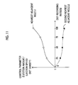
Fig. 11 is a graph illustrating a determination example of a dot gain control parameter of the nearest adjacent nozzle and the second nearest adjacent nozzle. -
Fig. 12 is a schematic explanatory diagram regarding an effect of non-ejection correction. -
Fig. 13 is a schematic block diagram illustrating a main configuration for realizing an ejection condition determination method according to a second embodiment. -
Fig. 14 is a specific flowchart regarding an acquisition method of drawing data in step S4A ofFig. 5 . -
Fig. 15 is a cross-sectional side view illustrating a configuration of an image forming apparatus. -
Fig. 16 is an electrical block diagram illustrating a system configuration of the image forming apparatus shown inFig. 15 . -
Figs. 17A and 17B are transparent plan views illustrating other configuration examples of the recording head shown inFig. 1 . - Hereinafter, an ejection condition determination method according to the present invention will be described in detail using preferred embodiments in a relationship with an image forming method and an image forming apparatus which performs the method. In this specification, to form an image is referred to as "printing" in some cases.
- Configuration according to first embodiment
- Schematic block diagram
-
Fig. 1 is a schematic block diagram illustrating a main configuration for realizing an ejection condition determination method according to a first embodiment. - An ejection
condition determination portion 10, which is a core of the embodiment of the present invention, determines an ejection condition ofdroplets 14 in an image forming apparatus 100 (refer toFigs. 15 and16 ) which forms a color image or a monochrome image formed by a plurality of dots on a sheet 12 (recording medium). In addition, the ejectioncondition determination portion 10 is capable of sending and receiving a variety of data to and from ascanning device 16 and adata storage portion 18. - The ejection
condition determination portion 10 includes a drawingdata acquisition section 22, afilter processing section 24, and apattern evaluation section 26. The drawingdata acquisition section 22 acquires drawing data representing an image adjusting chart 20 (refer toFigs. 1 and7A ) described later. Thefilter processing section 24 performs a filter processing corresponding to human visual characteristics on the drawing data. Thepattern evaluation section 26 evaluates a flat pattern 70 (refer toFig. 7B ) according to a predetermined evaluation condition. - The
scanning device 16 optically reads an image on a printed matter including theimage adjusting chart 20 so as to generate digital data. Thescanning device 16 may be a flat scanner provided for reading a reflected original document, or may be a film scanner provided for reading a transmitted original document. - The
data storage portion 18 stores a variety of data required to perform this determination method. In this drawing example, the data storage portion stores chartimage data 28, a plurality of kinds of visualcharacteristic data items 30, a plurality of kinds of evaluationcondition data items 32, andejection condition data 34. - A
head driver 38 is a driving circuit which controls driving of four recording heads 40 based on a control signal provided for forming an image so as to eject thedroplets 14 at appropriate timing. Here, a single pass type is shown in which thesheet 12 is transported only once in the arrow Y direction crossing (perpendicular to) the arrow X direction in a state of fixing eachrecording head 40 which is a line head extending in the arrow X direction. - Configuration of
recording head 40 -
Fig. 2 is a transparent plan view illustrating a structure example of therecording head 40 shown inFig. 1 .Fig. 3 is a schematic cross-sectional view taken along the line III-III ofFig. 2 . - As shown in
Fig. 2 , therecording head 40 includes a plurality of ink chamber units 42 (recording elements) which are arranged in a zigzag matrix. Eachink chamber unit 42 includes anozzle 44, apressure chamber 45, and asupply port 46. In thepressure chamber 45 which has a substantially rectangular planar shape, an outflow port to thenozzle 44 side is provided at one corner of both corners disposed diagonally, and an inflow port (the supply port 46) from acommon channel 48 is provided at the other corner thereof. - As shown in
Fig. 3 , eachpressure chamber 45 communicates with thecommon channel 48 via thesupply port 46. In addition, thecommon channel 48 communicates with an ink tank (not shown) which is a supply source of an ink (color material). Thus, the ink supplied from the ink tank is distributed and supplied to eachpressure chamber 45 via thecommon channel 48. - One surface (corresponding to an upper surface in the example of
Fig. 3 ) of thepressure chamber 45 is constituted by apressing plate 50, and thepressing plate 50 is also used as a common electrode. Apiezoelectric element 52 which is an actuator giving pressure to thepressing plate 50 so as to be deformed is joined onto thepressing plate 50. In addition, anindividual electrode 54 is formed on the upper surface of thepiezoelectric element 52. - When a driving voltage is applied between two electrodes, that is, the
pressing plate 50 which is a common electrode and theindividual electrode 54, thepiezoelectric element 52 interposed between the two electrodes is deformed. This physical deformation causes a volume of thepressure chamber 45 to vary, and thus the ink is pushed outward from thenozzle 44 and is ejected as the droplets 14 (refer toFig. 1 ). In addition, after thedroplets 14 are ejected, an ink refills thepressure chamber 45 via thesupply port 46 from thecommon channel 48 when the displacement of thepiezoelectric element 52 returns to an original state. - Referring to
Fig. 2 again, an arrangement feature of thenozzles 44 will be described. InFig. 2 , a longitudinal direction and a transverse direction of therecording head 40 are respectively defined as an arrow X direction and an arrow Y direction. In this case, a transport direction (refer toFig. 1 ) of thesheet 12 is perpendicular to the arrow X direction and is parallel to the arrow Y direction. - The
respective nozzles 44 in the L1-th line are disposed at the same interval with a predetermined gap (corresponding to four unit lengths) in the arrow X direction. The respective nozzles in the L2-th to L4-th lines are also disposed in the same manner as in the L1-th line. Hereinafter, the arrow X direction is referred to as an "arrangement direction" of the nozzles 44 (the ink chamber units 42) in some cases. - Each
nozzle 44 in the L2-th line is disposed at a position which is shifted by one unit length to the left in the arrow X direction from the position of eachnozzle 44 in the L1-th line. Eachnozzle 44 in the L3-th line is disposed at a position which is shifted by one unit length to the left in the arrow X direction from the position of eachnozzle 44 in the L2-th line. Eachnozzle 44 in the L4-th line is disposed at a position which is shifted by one unit length to the left in the arrow X direction from the position of eachnozzle 44 in the L3-th line. Therefore, an actual gap (projected nozzle pitch) between thenozzles 44 projected so as to be arranged in the longitudinal direction of therecording head 40 becomes small for high density. -
Fig. 4 is a schematic explanatory diagram illustrating a correspondence relationship between a first arrangement example of a plurality ofnozzles 44 included in therecording head 40 and an ejection order onto thesheet 12. For convenience of description, a case of using twentynozzles 44 will be described as an example. - Each cell in the rectangular lattice shown in
Fig. 4 indicates a region of one pixel in a formed image. The blank cell indicates an image position where the droplets 14 (refer toFig. 1 ) are not ejected (landed) yet at each ejection time point (t). In addition, the arabic numeral shown in the cell corresponds to a time point (ejection time points t=1 to 7) when thedroplets 14 are ejected at the image position thereof. - For example, a plurality of dots are sequentially formed by the
droplets 14 ejected between the ejection time points t=1 and 4, so as to generate a first image line. In addition, a plurality of dots are sequentially formed by thedroplets 14 ejected between the ejection time points t=4 and 7, so as to generate a fourth image line. In other words, dots are sequentially formed at a plurality of (four inFig. 4 ) timings so as to generate (complete) each image line. - Operation of ejection
condition determination portion 10 - Next, an operation of the ejection
condition determination portion 10 shown inFig. 1 will be described in detail with appropriate reference to a flowchart ofFig. 5 and other drawings. - In step S1, at least one nozzle 44 (a so-called defective nozzle) in which an ejection operation of the
droplets 14 is not favorable is specified among a plurality ofnozzles 44 included in therecording head 40. -
Fig. 6 is a schematic plan view illustrating an example of anozzle specifying chart 60. As shown inFig. 6 , a plurality ofline images 62 parallel to the arrow Y direction are formed on thenozzle specifying chart 60. In order to clarify a relationship between eachnozzle 44 and eachline image 62, a method of forming thenozzle specifying chart 60 will be described below. - First, the
droplets 14 are ejected from therespective nozzles 44 at intervals of three among thenozzles 44 belonging to the L1-th line, so as to form aline image group 64 of one row. Next, thedroplets 14 are ejected fromother nozzles 44, for example,respective nozzles 44 adjacent rightward to the initially usednozzles 44, so as to form aline image group 66 of one row. When this operation is sequentially performed four times, theline images 62 formed by only thenozzles 44 belonging to the L1-th line are disposed in the number corresponding to the number of thenozzles 44 belonging to the L1-th line on thesheet 12. - As above, it is possible to check an ejection operation of each
nozzle 44 on thenozzle specifying chart 60 by respectively forming theline images 62 using therespective nozzles 44 of the L2-th to L4-th lines in the same manner as in the L1-th line. For example, in a case where noline image 62 is formed, anozzle 44 corresponding to theline image 62 is specified not to eject thedroplets 14. In addition, in a case where theline image 62 is relatively tilted, anozzle 44 corresponding to theline image 62 is specified to cause curved ejection (i.e., abnormal meniscus). - The
nozzle specifying chart 60 may be checked through visual observation, and then identification information of a specifiednozzle 44d may be input through a manual operation. Alternatively, thenozzle specifying chart 60 may be read using an image reading mechanism embedded in the image forming apparatus 100 (refer toFig. 15 ) while printing the nozzle specifying chart, and then a specifiednozzle 44d may be automatically detected thereby identification information of the automatically detected nozzle may be input. - In addition, in subsequent steps S2 to S10, an ejection condition of the
other nozzles 44 is determined so as to perform non-ejection correction of the nozzle 44 (hereinafter, a specifiednozzle 44d; refer toFig. 4 ) specified in step S1. Here, the "non-ejection correction" indicates an image correction technique of stopping an ejection operation of the specifiednozzle 44d in which an ejection operation of thedroplets 14 is not normal and compensating for a density variation (mainly, a density reduction) of an image due to this stopping. - In step S2, two or more kinds of ejection conditions regarding the
other nozzles 44 than the specifiednozzle 44d are selected. Here, the ejection condition indicates a set of combinations of kinds and values of control parameters regarding ejection control of eachnozzle 44. The ejection condition includes, for example, position information of thenozzle 44, identification information (identification number, the number of continuous nozzles, or the like) of the specifiednozzle 44d, dot forming conditions, grayscale level information (halftone %), color information (the kind of color plate, or the like), and combinations thereof. The position information of thenozzle 44 may include, for example, a relative position to the specifiednozzle 44d, a pitch of thenozzles 44, a positional relationship in the recording head 40 (for example, attributes of the L1-th to L4-th lines shown inFig. 2 ), and the like. The dot forming conditions are various conditions for forming dots through ejection of thedroplets 14, and include, for example, at least one of an ejection amount of thedroplets 14, an ejection rate thereof, and a dot density (so-called recording density). - In this embodiment, ejection conditions in which dot forming conditions for nozzles in a vicinity of the specified
nozzle 44d, for example, at least one of (for example, four)nozzles 44 adjacent thereto are different are selected, respectively. - In step S3, the
image adjusting chart 20 on which the respective ejection conditions selected in step S2 are reflected is printed using the image forming apparatus 100 (refer toFig. 15 ). Specifically, thehead driver 38 acquires thechart image data 28 stored in thedata storage portion 18, and then controls driving of eachrecording head 40 so as to obtain theimage adjusting chart 20. - As shown in
Fig. 7A , a plurality of flat patterns 70 (drawing patterns) having uniform colors (for example, the substantially same light reflectance, luminance and density), nine patterns in the example ofFig. 7A are drawn in eachimage adjusting chart 20. Eachflat pattern 70 may be obtained by forming the same drawing pattern (here, an image with the same pixel value) by using each ejection condition determined in step S2 in a state in which thedroplets 14 are not ejected from the specifiednozzle 44d (hereinafter, a specified non-ejection state). For this reason, the respectiveflat patterns 70 macroscopically have the approximately same density but microscopically have different density distributions. - In addition, in the present specification, a two-dimensional distribution of a color of an image is referred to as a "density distribution", but an index for indicating a color of an image is not limited to an "optical density". In other words, all indexes (for example, light reflectance, luminance, luminosity, and the like) indicating a color of an image may be employed as a two-dimensional distribution.
- In the example of
Fig. 7A , a dot gain of nozzles 44 (hereinafter, the nearestadjacent nozzles 44n; refer toFig. 4 ) closest to the specifiednozzle 44d from the lower side to the upper side increases in the sameimage adjusting chart 20. In addition, a dot gain of nozzles (hereinafter, the second nearestadjacent nozzles 44m; refer toFig. 4 ) which are the second closest from left to right increases. - As shown in
Fig. 7B , theflat pattern 70 includes anon-ejection region 72 which is an image region corresponding to a position of the specifiednozzle 44d,adjustment target regions 74 which are image regions corresponding to positions of the nearestadjacent nozzles 44n and the second nearestadjacent nozzles 44m, andnon-adjustment target regions 76 which are image regions corresponding to positions of theother nozzles 44. Here, the "image region corresponding to a position of thenozzle 44" mainly indicates an image region in which a color is formed on therecording medium 12 through ejection of thedroplets 14 from the correspondingnozzle 44. Particularly, thenon-adjustment target region 76 is used as a reference image so as to clarify adjustment targets of the image in thenon-ejection region 72 and theadjustment target region 74. - In addition, the specified non-ejection state may be realized by setting a control signal value corresponding to an ejection position of the specified
nozzle 44d to 0, or the specified non-ejection state may be realized by directly giving a non-ejection command to thehead driver 38. - Further, a form of a drawing pattern forming the
image adjusting chart 20 may employ a geometric pattern such as a stripe, a circle, a dot, or a mark other than the flat pattern. Particularly, it is more preferable to use theflat pattern 70 in which an image quality difference is most easily detected. - Further, in the example of
Fig. 7A , for easy discrimination, the respectiveflat patterns 70 are disposed spaced apart from each other with a specific gap in theimage adjusting chart 20. A form of the flat pattern is not limited thereto, and, for example, the flat pattern may be an integrated pattern without a space. In this case, it is normally difficult to differentiate ejection condition differences from each other on an image, and thus a variety of information with which a position of each drawing pattern is specified is preferably held in advance. - In step S4, the drawing
data acquisition section 22 acquires drawing data representing theimage adjusting chart 20 formed in step S3. Before the acquisition, thescanning device 16 optically reads the image of the image adjusting chart 20 (including the nine flat patterns 70) so as to be supplied to the ejectioncondition determination portion 10 side. Further, the drawingdata acquisition section 22 acquires the obtained digital data (device-dependent data such as RGB, and optical physical quantities such as reflectance and transmittance) as drawing data without modification, or converts the digital data into device-independent data such as L*a*b. - Here, an image reading direction may be determined based on an optical transfer function (OTF) of the
scanning device 16. Specifically, an axis direction with higher OTF of two axis directions of an image reading region is made to match a horizontal direction (the arrangement direction of thenozzles 44; the X direction) of theimage adjusting chart 20 shown inFig. 7A , and thus it is possible to suppress influence of sharpness decrease caused by thescanning device 16. - In step S5, the ejection
condition determination portion 10 selects one data item from each of a plurality of visualcharacteristic data items 30 and a plurality of evaluationcondition data items 32. For example, the data item may be selected depending on the kind ofimage adjusting chart 20 or may be selected by receiving an input operation by a user. - In step S6, the
filter processing section 24 performs a filter processing in which one visualcharacteristic data item 30 selected in step S5 has acted on the drawing data acquired in step S4. Here, the "filter processing" indicates an image process of modulating a spatial frequency component (spectral intensity) of an image. -
Fig. 8 is a graph of a Dooley-Shaw function (observation distance 300 mm). This function is a kind of visual transfer function (VTF) and is a representative function which models human standard visual response characteristics. Specifically, the function corresponds to the square value of contrast ratio characteristics of luminance. The transverse axis of the graph expresses a spatial frequency (the unit: cycle/mm), and the longitudinal axis expresses a value (the unit is dimensionless) of the VTF. - The
filter processing section 24 performs inverse Fourier transform (for example, IFFT) on the square root of the VTF shown inFig. 8 so as to calculate a mask on the real space corresponding to the VTF in advance. Then, thefilter processing section 24 performs a convolution operation on the drawing data acquired from the drawingdata acquisition section 22 by using a mask corresponding to a resolution thereof. Thus, it is possible to obtain visual correction drawing data. - In addition, a function shape of visual characteristics is not limited thereto, and various visual characteristics derived from mathematical models, test data, or the like may be employed. Further, an observation distance may not only correspond to 300 mm but be also variously changed depending on observation aspects or evaluation references of an image, or the like.
- In addition, in order to appropriately reflect a correction effect through the above-described filter processing, a pixel value of drawing data is preferably converted into an (preferably, linear) amount with high correlation with an amount of light reflected by or transmitted through an image. As an example thereof, RGB values, tristimulus values (XYZ), light reflectance in a case of a reflection original document, light transmittance in a case of a transmission original document, or the like may be used.
- In step S7, the
pattern evaluation section 26 evaluates two or moreflat patterns 70 which have been subjected to the filter processing according to the evaluationcondition data items 32 selected in step S5. Hereinafter, a specific example of the evaluation will be described in detail. -
Figs. 9A and 9B are schematic explanatory diagrams regarding an evaluation method of theflat pattern 70. Aprofile 78 common to both ofFigs. 9A and 9B indicates a microscopic density distribution from one end E1 to the other end E2 (refer toFigs. 7A and 7B ) of theflat pattern 70. Theprofile 78 has two peaks indicating maximum points of an image density and three peaks indicating minimum points of the image density. In addition, anideal line 79 indicated by the broken line inFigs. 9A and 9B corresponds to an average density (an ideal density) at a position which is sufficiently spaced apart from the specifiednozzle 44d. - The
pattern evaluation section 26 may evaluate eachflat pattern 70 by placing importance on an extent in which stripe unevenness occurs. As shown inFig. 9A , a difference P1 between the maximum value and an ideal density may be an evaluation value, or a difference P2 between the maximum value and the minimum value of the image density may be an evaluation value. In this case, the smaller the difference P1 or P2, the higher an evaluation, and, the larger the difference P1 or P2, the lower an evaluation. - The
pattern evaluation section 26 may evaluate eachflat pattern 70 by placing importance on macroscopic reproducibility of an image density. As shown inFig. 9B , when, with respect to theideal lines 79, the areas of two regions on the upper side are respectively indicated by Sp1 and Sp2, and the areas of three regions on the lower side are respectively Sm1, Sm2, and Sm3, the integral St=|(Sp1+Sp2)-(Sm1+Sm2+Sm3)| may be an evaluation value. In this case, the smaller the integral St, the higher an evaluation, and, the larger the integral St, the lower an evaluation. - In addition, a method of calculating an evaluation value is not limited thereto, and various methods or indexes appropriate for quantification of density unevenness of an evaluation target, and combinations thereof, may be used. As an example of an evaluation method, in addition to the above-described statistical process, well-known image processing methods including a feature amount extraction process may be performed. Specifically, a low-pass filter may be applied in a case of evaluating strip unevenness having a component of a low spatial frequency band, and a high-pass filter or an edge detection filter may be applied in a case of evaluating stripe unevenness having a component of a high spatial frequency band. In addition, this process may be performed separately from/together with the above-described filter processing (step S6).
- Further, from the viewpoint of an averaged error, a longitudinal axis of the
profile 78 is preferably converted into an (preferably, linear) amount with high correlation with an amount of light reflected by or transmitted through an image. As an example thereof, RGB values, tristimulus values (XYZ), light reflectance in a case of a reflection original document, light transmittance in a case of a transmission original document, or the like may be used. - In step S8, the ejection
condition determination portion 10 discriminates whether or not to finish this evaluation based on the evaluation result obtained in step S7. The ejectioncondition determination portion 10 discriminates whether or not there is at least oneflat pattern 70 which satisfies an evaluation reference capable of realizing image quality of an allowable level. If it is discriminated that there is no flat pattern, the flow returns to step S2, and a different ejection condition different from in the previous time is selected again, and steps S2 to S8 are sequentially repeatedly performed. On the other hand, if it is discriminated that there is at least one flat pattern, the flow proceeds to the next step (S9). In addition, the flow may proceed to the next step (S9) without performing the discrimination process. - In step S9, the ejection
condition determination portion 10 determines an optimal ejection condition on the basis of the evaluation result obtained in step S7. For example, the ejectioncondition determination portion 10 may determine an ejection condition having the highest evaluation result among a plurality of ejection conditions as an optimal ejection condition. Alternatively, the ejectioncondition determination portion 10 may estimate an evaluation value in an intermediate ejection condition from a relationship between a plurality of ejection conditions and evaluation values, and may determine an ejection condition which is expected to obtain the highest evaluation result as an optimal ejection condition. - In step S10, the optimal ejection condition determined in step S9 is set and is preserved. Specifically, the ejection
condition determination portion 10 sends data regarding the optimal ejection condition so as to be stored in thedata storage portion 18. - In this way, an operation of the ejection
condition determination portion 10 is completed. An optimal ejection condition in which a plurality of control parameters are variously combined may be determined by repeatedly performing the flowchart ofFig. 5 as necessary. - For example, there are cases where it is difficult to perform an operation of determining an optimal control parameter when an image is adjusted using
nozzles 44 around the specifiednozzle 44d, the nearestadjacent nozzles 44n, the second nearestadjacent nozzles 44m, and theother nozzles 44. Specifically, even if density unevenness (a relatively thin stripe unevenness due to non-ejection or landing position deviation of the droplets 14) of a high spatial frequency band is reduced as a result of image adjustment, density unevenness of a low spatial frequency band caused by thenozzle 44 for which a control parameter is adjusted may become more obvious. Similarly, as a result of suppressing density unevenness of a low spatial frequency band, density unevenness of a high spatial frequency band may become more obvious. - Therefore, a method may be employed in which a dot forming condition for each
nozzle 44 is sequentially determined through sequential repetition of steps S2 to S9 ofFig. 5 , and then a final ejection condition is fixed. Particularly, an ejection condition is preferably sequentially determined for thenozzles 44 located on the outside in a predetermined direction (for example, an arrangement direction) from the specifiednozzle 44d. -
Figs. 10A to 10D are schematic explanatory diagrams illustrating a determination process of a dot gain control parameter.Fig. 10A shows the nearestadjacent nozzles 44n, the second nearestadjacent nozzles 44m, and the third nearestadjacent nozzles 441 in an order of being close to the specifiednozzle 44d. For convenience of description, a state is shown in which sevennozzles 44 are disposed in a line. In addition,Figs. 10B to 10D are the same asFig. 10A . - The circle with X indicates the specified
nozzle 44d. In addition, the normal circle indicates anozzle 44 of which a dot gain control parameter is a default value and a dot gain is not adjusted. Further, the hatched circle indicates anozzle 44 of which a value of a dot gain control parameter is variously changed. Furthermore, the filled circle indicates anozzle 44 of which a value of a dot gain control parameter is fixed. - In the first image adjustment, two or more kinds of ejection conditions in which values of the dot gain control parameters of the two nearest
adjacent nozzles Fig. 10B ). Here, the dot gain control parameters of the two second nearestadjacent nozzles adjacent nozzles - In the second image adjustment, after a value of the dot gain control parameter of each of the nearest
adjacent nozzles adjacent nozzles Fig. 10C ). - Next, if it is determined that image quality is in an allowable level, a value of the dot gain control parameter of each of the second nearest
adjacent nozzles Fig. 10D ). As such, the number ofnozzles 44 which is a control parameter is reduced so as to narrow options, thereby improving efficiency of the adjustment operation. In addition, a dot forming condition is sequentially determined in an order in which an adjustment amount (a variation amount from a reference value) of a dot gain is large, and thus an image adjustment performance is rapidly improved. - On the other hand, conversely to the above description, if sequential determination is performed from the outside of the specified
nozzle 44d to the inside in a predetermined direction (for example, an arrangement direction), this is not efficient from the viewpoint of image adjustment since a dot forming condition is determined in an order in which an adjustment amount of a dot gain is small. - In addition, although values of control parameters are determined independently from each other in the above-described example, values of control parameters may be determined under any constraints. An example of the constraint may include an upper limit of a total amount of ink to be used, an operation range of a control parameter, or the like.
-
Fig. 11 is a graph illustrating an example of determining control parameters of the nearestadjacent nozzles 44n and the second nearestadjacent nozzles 44m, and shows an example (look-up table) of a data format in the ejection condition data 34 (refer toFig. 1 ). The transverse axis of this graph expresses a dot recording ratio (unit: %), and the longitudinal axis thereof expresses a control parameter. In addition, the control parameter has a standard value of 1, is a variable which is proportional to a dot gain (or a dot density), and is correlated with an ejection amount or ejection speed (or halftone %) of thedroplets 14. - As understood from
Fig. 11 , a control parameter for compensating for a density variation of an image due to a specified non-ejection state is set. In other words, dot gains of the nearestadjacent nozzles 44n are relatively increased so as to increase a density around the ejection position of the specifiednozzle 44d. In addition, dot gains of the second nearestadjacent nozzles 44m are relatively reduced so as to reduce densities around the ejection positions of the nearestadjacent nozzles 44n. - Effects according to this ejection condition determination method.
- Returning to
Fig. 1 , theejection condition data 34 which is stored in thedata storage portion 18 in advance is referred to when an image is formed on thesheet 12 using therecording head 40. In other words, thehead driver 38 multiplies a dot gain corresponding to eachnozzle 44 by an input control signal, and controls ejection of eachrecording head 40 on the basis of an obtained signal value. Thus, it is possible to realize non-ejection correction on any image. - As shown in
Fig. 12 , in a case where curved ejection occurs in the specifiednozzle 44d, visible white stripe unevenness and black stripe unevenness are generated on animage 90. In contrast, it is possible to obtain afavorable image 91 on which stripe unevenness is not viewed by selecting an appropriate ejection condition. In addition, dot gains of the second nearestadjacent nozzles 44m are relatively reduced so as to achieve a so-called decimation effect and to thereby improve robustness to disparity between landing positions and landing interference of thedroplets 14 ejected from the nearestadjacent nozzles 44n. Accordingly, it is possible to obtainfavorable images - As described above, since a filter processing corresponding to human visual characteristics (the visual characteristic data items 30) is performed on drawing data representing two or more
flat patterns 70 which are different in density distribution, it is possible to obtain drawing data representing a drawing form closer to a manner viewed by a user, that is, visual correction drawing data. In addition, since an ejection condition (the ejection condition data 34) for compensating for a density variation of an image caused by a specified non-ejection state is determined based on an evaluation result obtained by respectively evaluating the two or moreflat patterns 70 having been subjected to the filter processing according to predetermined evaluation conditions (the evaluation condition data items 32), it is possible to automatically determine an optimal ejection condition while comparing and evaluating two or more kinds of ejection conditions, respectively. Therefore, it is possible to considerably reduce the number of operation steps and to determine an ejection condition conforming to a user's sense. - Configuration according to second embodiment
-
Fig. 13 is a schematic block diagram illustrating a main configuration for realizing an ejection condition determination method according to a second embodiment. In addition, the same constituent elements as in the first embodiment have the same reference numerals and description thereof will be omitted. - The second embodiment has the substantially same configuration as the first embodiment shown in
Fig. 1 but is different in that animage creation device 80 is provided instead of thescanning device 16. Theimage creation device 80 includes aninformation input portion 82 which inputs a variety of information (hereinafter, image forming information) for forming an image in an image forming apparatus 100 (refer toFig. 15 ), and a drawingdata creation portion 84 which creates digital data simulating the image adjusting chart 20 (refer toFig. 7A ) by using the image forming information input by theinformation input portion 82. - Operation of ejection
condition determination portion 10 - Next, an operation of the ejection
condition determination portion 10 shown inFig. 13 will be described. This operation is basically the same as in the flowchart ofFig. 5 , but step S4A is executed instead of step S4 for reading an image of theimage adjusting chart 20. Hereinafter, a detailed description thereof will be made with appropriate reference to the flowchart ofFig. 14 and other drawings. - In step S4A-1, the
information input portion 82 inputs image forming information provided for creating an image. Here, the image forming information includes a variety of information regarding theimage forming apparatus 100 including an output resolution, a variety of information regarding ink or therecording medium 12, and a variety of information regarding a drawing specification of theimage adjusting chart 20 including the above-described ejection condition. - In step S4A-2, the drawing
data creation portion 84 creates digital data simulating the image adjusting chart 20 (refer toFig. 7A ) by using the image forming information input in step S4A-1. The drawingdata acquisition section 22 acquires the obtained digital data as drawing data without modification, or converts the digital data into device-independent data such as L*a*b. - In step S4A-3, the drawing
data acquisition section 22 acquires the digital data created in step S4A-2. In the present embodiment, theimage creation device 80 and the ejectioncondition determination portion 10 are shown as different constituent elements, but each function of theinformation input portion 82 and the drawingdata creation portion 84 may be executed by the ejectioncondition determination portion 10. - In the above-described way, the drawing
data acquisition section 22 acquires the drawing data simulating the image adjusting chart 20 (step S4A). - In addition, unlike in the first embodiment, since a drawing specification (for example, a definition of a pixel value and a position in the unit of a pixel) in the drawing data is known, it is possible to efficiently perform a filter processing (step S6 of
Fig. 5 ) or evaluation (step S7 ofFig. 5 ) of each drawing pattern by using this information. In addition, as shown inFigs. 10A to 10D , an ejection condition of thedroplets 14 may be sequentially determined. - Effects according to this ejection condition determination method.
- As above, image forming information regarding the image forming apparatus 100 (refer to
Fig. 15 ) is input, and digital data simulating a difference in density distribution on theimage adjusting chart 20 is created using the image forming information. Therefore, it is possible to easily determine an ejection condition conforming to a user's sense without actually forming theimage adjusting chart 20. Particularly, since consumable materials such as ink or therecording medium 12 are not necessary, costs are reduced. - Configuration of
image forming apparatus 100 - Successively, a description will be made of an ejection condition determination method related to the above-described first and second embodiments and the
image forming apparatus 100 capable of realizing an image forming method using this method.Fig. 15 is a cross-sectional side view illustrating a configuration of theimage forming apparatus 100. - The
image forming apparatus 100 is provided with a paper feeding andtransport portion 114 which feeds and transports thesheet 12 on the upstream side in the transport direction of the sheet 12 (in the example ofFig. 15 , flat paper). A treatmentliquid application portion 116 which applies a treatment liquid on a recording surface (hereinafter, referred to as an image forming surface) of thesheet 12, animage forming portion 118 which forms an image by attaching the droplets 14 (refer toFig. 1 ) of ink onto the image forming surface, anink drying portion 120 which dries ink of a treatment liquid layer formed on thesheet 12, animage fixing portion 122 which fixes the image of the treatment liquid layer to thesheet 12, and adischarge portion 124 which discharges thesheet 12 to which the image is fixed, are provided on the downstream side of the paper feeding andtransport portion 114 in the transport direction of thesheet 12. - The paper feeding and
transport portion 114 includes a stackingsection 126 which is provided so as to stack thesheets 12, apaper feeding section 128 which feeds thesheets 12 stacked on the stackingsection 126 one by one, and atransport section 130 which transports thesheet 12 fed by thepaper feeding section 128 to the treatmentliquid application portion 116. - The treatment
liquid application portion 116 includes a treatmentliquid application drum 132 which is rotatably provided, a treatmentliquid application device 134 which applies a treatment liquid on the image forming surface of thesheet 12, and a treatmentliquid drying device 136 which dries the treatment liquid. Thus, a thin treatment liquid layer is applied on the image forming surface of thesheet 12. - A first
intermediate transport drum 138 is rotatably disposed between the treatmentliquid application portion 116 and theimage forming portion 118. The firstintermediate transport drum 138 is rotated in a state in which thesheet 12 is held on the surface of the firstintermediate transport drum 138, and thus thesheet 12 supplied from the treatmentliquid application portion 116 side is transported to theimage forming portion 118 side. - The
image forming portion 118 includes an image forming drum 140 (transport section) which is rotatably provided, and ahead unit 142 which ejects thedroplets 14 onto thesheet 12 transported by theimage forming drum 140. Thehead unit 142 includes the recording heads 40 (refer toFig. 1 ) of at least Y (yellow), M (magenta), C (cyan), and K (black) which are primary colors. In addition, the respective recording heads 40 are arranged in the circumferential direction of theimage forming drum 140. Therefore, images of the respective colors are sequentially formed on the treatment liquid layer applied on the image forming surface of thesheet 12. Further, the treatment liquid has an effect of condensing color materials (pigments) and latex particles dispersed in a solvent of the ink, and thus can prevent the color materials from flowing on thesheet 12. - A second
intermediate transport drum 146 which is rotatably provided is disposed between theimage forming portion 118 and theink drying portion 120. The secondintermediate transport drum 146 is rotated in a state in which thesheet 12 is held on the surface of the secondintermediate transport drum 146, and thus thesheet 12 supplied from theimage forming portion 118 side is transported to theink drying portion 120 side. - The
ink drying portion 120 includes anink drying drum 148 which is rotatably provided, and a plurality ofhot air nozzles 150 and a plurality of infrared heaters (heaters 152) which dry the treatment liquid layer of thesheet 12. Thus, the solvent of the ink remaining in the treatment liquid layer of thesheet 12 is dried. - A third
intermediate transport drum 154 which is rotatably provided is disposed between theink drying portion 120 and theimage fixing portion 122. The thirdintermediate transport drum 154 is rotated in a state in which thesheet 12 is held on the surface of the thirdintermediate transport drum 154, and thus thesheet 12 supplied from theink drying portion 120 side is transported to theimage fixing portion 122 side. - The
image fixing portion 122 includes animage fixing drum 156 which is rotatably provided, aheating roller 158 which is disposed so as to be close to the surface of theimage fixing drum 156, and a fixingroller 160 which is disposed in a state of coming into pressing contact with the surface of theimage fixing drum 156. Therefore, the latex particles condensed in the treatment liquid layer are heated and pressed and are thus fixed onto thesheet 12 as an image. - The
sheet 12 to which the image of the image forming surface is fixed through the above-described respective steps is transported to thedischarge portion 124 side provided on the downstream side of theimage fixing portion 122 through rotation of theimage fixing drum 156. - Description of control system of
image forming apparatus 100 -
Fig. 16 is a block diagram illustrating a system configuration of theimage forming apparatus 100 shown inFig. 15 . Theimage forming apparatus 100 includes not only thedata storage portion 18, the head driver 38 (refer toFig. 1 with regard to both of the two), thehead unit 142, and the heater 152 (refer toFig. 15 with regard to both of the two), but also acommunication interface 162, asystem controller 164, animage memory 166, aROM 168, amotor driver 170, amotor 172, aheater driver 174, aprinting control portion 176, animage buffer memory 180, and aROM 182. - The
communication interface 162 is an interface portion with a host apparatus 190, and is used for a user to instruct theimage forming apparatus 100 to form an image or the like. Thecommunication interface 162 may employ a serial interface such as a universal serial bus (USB), IEEE1394, Ethernet (registered trademark), or a wireless network, or a parallel interface such as Centronics. A buffer memory (not shown) for speeding up communication may be mounted in this portion. - An image signal sent from the host apparatus 190 is received by the
image forming apparatus 100 via thecommunication interface 162 and is temporarily stored in theimage memory 166. Theimage memory 166 is storage means for storing an image signal input via thecommunication interface 162, and reads and writes information via thesystem controller 164. Theimage memory 166 is not limited to a memory formed by semiconductor elements, and may use a magnetic medium such as a hard disk. - The
system controller 164 includes a central processing unit (CPU) and peripheral circuits, functions as a control device controlling the overallimage forming apparatus 100 according to a predetermined program, and functions as an operation device including the ejectioncondition determination portion 10 and performing various operations. In other words, thesystem controller 164 controls the respective portions such as thecommunication interface 162, theimage memory 166, themotor driver 170, and theheater driver 174. In addition, thesystem controller 164 performs communication control with the host apparatus 190, reading and writing control of theimage memory 166 and theROM 168, and the like. Further, thesystem controller 164 generates control signals for controlling themotor 172 and theheaters 152 of the sheet transport system. Furthermore, an image signal stored in theimage memory 166 as well as the control signal is transmitted to theprinting control portion 176. - The
ROM 168 stores programs executed by the CPU of thesystem controller 164 and a variety of data necessary for control. Theimage memory 166 is used as a temporary storage region of an image signal and is used as a development region of a program and an operation work region of the CPU. - The
motor driver 170 is a driver (driving circuit) which drives themotor 172 of the sheet transport system in response to an instruction from thesystem controller 164. Theheater driver 174 is a driver which drives theheaters 152 in response to an instruction from thesystem controller 164. - On the other hand, the
printing control portion 176 includes a CPU and peripheral circuits, and performs processes such as various processings for generating an ejection control signal from an image signal of theimage memory 166 and correction and supplies the generated ink ejection data (control signal) to thehead driver 38 so as to control ejection driving of thehead unit 142 under the control of thesystem controller 164. - The
printing control portion 176 includes theimage buffer memory 180, and an image signal or data such as a parameter is temporarily stored in theimage buffer memory 180 when theprinting control portion 176 processes the image signal. - The
printing control portion 176 is connected to theROM 182 which stores programs executed by the CPU of theprinting control portion 176 and a variety of data necessary for control. TheROM 182 may be read only storage means, but preferably uses rewritable storage means such as an EEPROM in a case where a variety of data is updated as necessary. - An
image processing section 184 generates dot disposition data for each ink color from an input image signal. In other words, a halftone process is performed on the input image signal so as to determine a dot forming position (ink ejection timing). The halftone process may employ an ordered dither method, an error diffusion method, a density pattern method, a random dot method, and the like. In addition, in a case where a dot density is changed so as to realize non-ejection correction, theimage processing section 184 may perform the halftone process after adjusting a part of the input image signal by referring to the ejection condition data 34 (refer toFig. 1 ) stored in thedata storage portion 18. - In addition, in the example of
Fig. 16 , the ejectioncondition determination portion 10 and theimage processing section 184 are respectively included in thesystem controller 164 and theprinting control portion 176. For example, the ejectioncondition determination portion 10 and/or theimage processing section 184 may be configured separately from thesystem controller 164 or theprinting control portion 176. - In addition, the
printing control portion 176 has an ink ejection data generation function of generating ink ejection data (a control signal of the actuators corresponding to thenozzles 44 of the recording head 40) and a driving waveform generation function on the basis of the dot disposition data generated by theimage processing section 184. - The ink ejection data generated using the ink ejection data generation function is sent to the
head driver 38 so as to control an ink ejection operation of thehead unit 142. During the control, the above-described non-ejection correction is performed by referring to the ejection condition data 34 (refer toFig. 1 ) stored in thedata storage portion 18. - The driving waveform generation function is a function of generating a driving signal waveform for driving the actuator corresponding to each
nozzle 44 of therecording head 40. A signal (driving waveform) generated using the driving waveform generation function is supplied to thehead driver 38. - Other configurations of
recording head 40 - A configuration of the
recording head 40 is not limited to the example ofFigs. 2 to 4 . For example, a shape of thepressure chamber 45 is not limited to this example, and various forms may be employed in which a planar shape is a tetragonal shape (a diamond shape, a rectangular shape, or the like), a pentagonal shape, a hexagonal shape, other polygonal shapes, a circular shape, an elliptical shape, and the like. - In addition, instead of the configuration of
Fig. 2 , as shown inFig. 17A ,short head modules 40a in which a plurality ofnozzles 44 are arranged in a two-dimensional manner may be arranged in a zigzag shape and be connected to each other so as to form a long line head. As shown inFig. 17B , a form may be employed in which headmodules 40b are arranged in a line and are connected to each other. - Further, an ejection mechanism of the
droplets 14 by therecording head 40 may employ various types. In addition to a type (refer toFig. 3 ) of ejecting thedroplets 14 through deformation of an actuator formed by a piezoelectric element and the like, a thermal jet type may be employed in which a heating element such as a heater heats ink so as to generate bubbles and thedroplets 14 are ejected by a pressure thereof. - In addition, the present invention is not limited to the above-described embodiment, and can be freely modified in the scope without departing from the spirit of the invention.
- Although, in the above-described embodiment, the graphic art (printing) usage is exemplified, an applicable scope of the present invention is not limited thereto. The present invention is applicable to various image forming apparatuses capable of forming an image pattern, such as, for example, a wire drawing apparatus of an electronic circuit board, a manufacturing device of various devices, a resist printing apparatus using a resin liquid as a functional liquid (corresponding to "ink") for ejection, and a micro-structure forming apparatus.
- In addition, although, in the above-described embodiment, only the
sheet 12 is transported through rotation of theimage forming drum 140, at least one of thehead unit 142 and thesheet 12 may be transported. The present invention is applicable to a configuration in which both of the head unit and thesheet 12 are relatively moved.
Claims (11)
- An ejection condition determination method in an image forming apparatus configured to relatively move a recording medium once with respect to a recording head including a plurality of recording elements configured to eject droplets in a transport direction crossing an arrangement direction of the plurality of recording elements, so as to form an image formed by a plurality of dots on the recording medium, the method comprising:selecting two or more kinds of ejection conditions regarding other recording elements than a specified recording element among the plurality of recording elements;acquiring drawing data representing two or more drawing patterns having different density distributions, the drawing data being acquired by respectively forming same drawing patterns using the selected two or more kinds of ejection conditions in a specified non-ejection state in which there is no ejection of the droplets from the specified recording element;performing a filter processing corresponding to human visual characteristics on the acquired drawing data so as to obtain visual correction drawing data; anddetermining the ejection conditions for compensating for a density variation of the image due to the specified non-ejection state based upon evaluation results which are obtained by respectively evaluating two or more drawing patterns represented by the visual correction drawing data and having been subjected to the filter processing according to a predetermined evaluation condition.
- The ejection condition determination method according to claim 1,
wherein, in the selecting of the two or more kinds of ejection conditions, the two or more kinds of ejection conditions are selected in which dot forming conditions for forming the dots are different for at least one of the recording elements adjacent to the specified recording element. - The ejection condition determination method according to claim 2,
wherein the dot forming condition includes at least one of an ejection amount of the droplets, an ejection speed of the droplets, and a dot density. - The ejection condition determination method according to claim 2 or 3,
wherein the selecting of the two or more kinds of ejection conditions, the acquiring of the drawing data, the performing of the filter processing, and the determining of the ejection conditions are sequentially repeatedly performed, so as to sequentially determine the dot forming condition for the recording elements and to fix the ejection conditions. - The ejection condition determination method according to claim 4,
wherein the dot forming conditions for the recording elements located outside the specified recording element in a predetermined direction are sequentially determined so as to fix the ejection conditions. - The ejection condition determination method according to any one of claims 1 to 5,
wherein the same drawing pattern is a flat pattern having a uniform color. - The ejection condition determination method according to any one of claims 1 to 6, further comprising:forming the two or more drawing patterns as the image on the recording medium by using the image forming apparatus,wherein, in the acquiring of the drawing data, the two or more formed drawing patterns are read using a scanning device adopted to optically read the image, so as to acquire the drawing data.
- The ejection condition determination method according to claim 7,
wherein, in the acquiring of the drawing data, the two or more drawing patterns are read in a reading direction which is determined according to optical transfer characteristics of the scanning device, so as to acquire the drawing data. - The ejection condition determination method according to any one of claims 1 to 6, further comprising:inputting image forming information regarding the image forming apparatus, wherein, in the acquiring of the drawing data, digital data simulating difference in density distribution is created using the input image forming information, so as to acquire the drawing data.
- An image forming method comprising:forming the image by controlling ejection of the recording head in the specified non-ejection state based upon the ejection conditions determined using the method according to any one of claims 1 to 9.
- An image forming apparatus comprising the recording head of which ejection is controlled in the specified non-ejection state based upon the ejection conditions determined using the method according to any one of claims 1 to 9, so as to form the image.
Applications Claiming Priority (1)
| Application Number | Priority Date | Filing Date | Title |
|---|---|---|---|
| JP2012209754A JP5743990B2 (en) | 2012-09-24 | 2012-09-24 | Discharge condition determining method, image forming method and image forming apparatus using the method |
Publications (2)
| Publication Number | Publication Date |
|---|---|
| EP2711188A1 true EP2711188A1 (en) | 2014-03-26 |
| EP2711188B1 EP2711188B1 (en) | 2018-11-07 |
Family
ID=49182143
Family Applications (1)
| Application Number | Title | Priority Date | Filing Date |
|---|---|---|---|
| EP13184760.0A Not-in-force EP2711188B1 (en) | 2012-09-24 | 2013-09-17 | Ejection condition determination method, image forming method, and image forming apparatus |
Country Status (3)
| Country | Link |
|---|---|
| US (1) | US9227400B2 (en) |
| EP (1) | EP2711188B1 (en) |
| JP (1) | JP5743990B2 (en) |
Families Citing this family (1)
| Publication number | Priority date | Publication date | Assignee | Title |
|---|---|---|---|---|
| CN107428163B (en) * | 2015-03-31 | 2019-12-27 | 柯尼卡美能达株式会社 | Ink jet recording apparatus, ink jet head driving method, and image forming method |
Citations (6)
| Publication number | Priority date | Publication date | Assignee | Title |
|---|---|---|---|---|
| US6390583B1 (en) * | 1999-04-19 | 2002-05-21 | Canon Kabushiki Kaisha | Information processing apparatus, printing apparatus, information processing method and printing method |
| JP2006076086A (en) | 2004-09-08 | 2006-03-23 | Fuji Xerox Co Ltd | Ink jet recorder and recording method |
| EP1681168A2 (en) * | 1998-04-03 | 2006-07-19 | Canon Kabushiki Kaisha | An adjustment method of dot printing positions and a printing apparatus |
| JP2007160748A (en) | 2005-12-14 | 2007-06-28 | Fujifilm Corp | Image recording device and image recording method |
| JP2011201121A (en) | 2010-03-25 | 2011-10-13 | Fujifilm Corp | Image processing method and device, inkjet drawing device, and correction-coefficient data-generating method |
| EP2465687A1 (en) * | 2010-12-17 | 2012-06-20 | Fujifilm Corporation | Defective recording element detecting apparatus and method, and image forming apparatus and method |
Family Cites Families (13)
| Publication number | Priority date | Publication date | Assignee | Title |
|---|---|---|---|---|
| JP4323580B2 (en) | 1998-04-03 | 2009-09-02 | キヤノン株式会社 | Printing apparatus and head driving method thereof |
| JP2006239999A (en) * | 2005-03-02 | 2006-09-14 | Canon Inc | Inkjet recorder |
| AU2005203031A1 (en) * | 2005-07-12 | 2007-02-01 | Canon Kabushiki Kaisha | Optical transfer function measurement system |
| JP4660439B2 (en) | 2006-08-08 | 2011-03-30 | セイコーエプソン株式会社 | Printing apparatus and printing method |
| JP2008080642A (en) * | 2006-09-27 | 2008-04-10 | Seiko Epson Corp | Printing method |
| JP2009172927A (en) * | 2008-01-25 | 2009-08-06 | Canon Finetech Inc | Inkjet recorder |
| JP5037469B2 (en) * | 2008-09-30 | 2012-09-26 | 富士フイルム株式会社 | Dot position measuring method, apparatus and program |
| US20100321437A1 (en) * | 2009-06-22 | 2010-12-23 | Olympus Corporation | Method for correcting unevenness in density for image recording apparatus |
| JP5545961B2 (en) * | 2010-02-10 | 2014-07-09 | 富士フイルム株式会社 | Image processing method, image recording method, image processing apparatus, and image recording apparatus |
| JP5528910B2 (en) * | 2010-06-02 | 2014-06-25 | 株式会社Pfu | Overhead image reader |
| JP5457307B2 (en) * | 2010-08-27 | 2014-04-02 | 富士フイルム株式会社 | Defective recording element compensation parameter selection chart, defective recording element compensation parameter determination method and apparatus, and image forming apparatus |
| JP5398019B2 (en) * | 2010-09-28 | 2014-01-29 | 富士フイルム株式会社 | Defective recording element compensation parameter determination method and apparatus, and image forming apparatus |
| JP5311688B2 (en) * | 2011-01-07 | 2013-10-09 | 富士フイルム株式会社 | Density unevenness correction value calculation method, image processing method, and image processing apparatus |
-
2012
- 2012-09-24 JP JP2012209754A patent/JP5743990B2/en not_active Expired - Fee Related
-
2013
- 2013-09-17 EP EP13184760.0A patent/EP2711188B1/en not_active Not-in-force
- 2013-09-23 US US14/034,227 patent/US9227400B2/en not_active Expired - Fee Related
Patent Citations (6)
| Publication number | Priority date | Publication date | Assignee | Title |
|---|---|---|---|---|
| EP1681168A2 (en) * | 1998-04-03 | 2006-07-19 | Canon Kabushiki Kaisha | An adjustment method of dot printing positions and a printing apparatus |
| US6390583B1 (en) * | 1999-04-19 | 2002-05-21 | Canon Kabushiki Kaisha | Information processing apparatus, printing apparatus, information processing method and printing method |
| JP2006076086A (en) | 2004-09-08 | 2006-03-23 | Fuji Xerox Co Ltd | Ink jet recorder and recording method |
| JP2007160748A (en) | 2005-12-14 | 2007-06-28 | Fujifilm Corp | Image recording device and image recording method |
| JP2011201121A (en) | 2010-03-25 | 2011-10-13 | Fujifilm Corp | Image processing method and device, inkjet drawing device, and correction-coefficient data-generating method |
| EP2465687A1 (en) * | 2010-12-17 | 2012-06-20 | Fujifilm Corporation | Defective recording element detecting apparatus and method, and image forming apparatus and method |
Also Published As
| Publication number | Publication date |
|---|---|
| EP2711188B1 (en) | 2018-11-07 |
| JP2014065147A (en) | 2014-04-17 |
| JP5743990B2 (en) | 2015-07-01 |
| US20140085656A1 (en) | 2014-03-27 |
| US9227400B2 (en) | 2016-01-05 |
Similar Documents
| Publication | Publication Date | Title |
|---|---|---|
| US8496313B2 (en) | Image processing method, image processing apparatus, inkjet image forming apparatus and correction coefficient data generating method | |
| US8573731B2 (en) | Density error correction | |
| US8733877B2 (en) | Method and apparatus for detecting discharge defect, image processing apparatus, computer-readable recording medium, and printing system | |
| JP5439426B2 (en) | Processing condition selection device, processing condition selection method, and program | |
| JP2010083007A (en) | Apparatus, method and program for processing image, and image recording apparatus | |
| KR101990277B1 (en) | System and method for printing with ink limiting | |
| JP2010188663A (en) | Image recording apparatus, image processing apparatus, method for processing image, and program | |
| JP5147625B2 (en) | Image forming apparatus, image forming method, and printing apparatus | |
| JP2006347164A (en) | Image recording apparatus and method, and method of determining density correction coefficients | |
| JP2010201638A (en) | Image recorder, image processor, image processing method, and program | |
| EP2711188B1 (en) | Ejection condition determination method, image forming method, and image forming apparatus | |
| US20160114607A1 (en) | Test chart-forming method, device and non-transitory recording medium, test chart, and image correction method | |
| JP5462891B2 (en) | Image forming apparatus and image forming method | |
| JP5702621B2 (en) | Image recording apparatus and image recording method | |
| JP2005096443A (en) | Inkjet recording apparatus and image forming method | |
| US8851608B2 (en) | Image forming apparatus | |
| JP2013123831A (en) | Image forming apparatus and image forming method | |
| JP2012066457A (en) | Image forming apparatus, correction value calculator, test chart for density measurement, and correction value calculation method | |
| EP2953338A1 (en) | Image formation device, method, program, and formed image | |
| JP7415581B2 (en) | Information processing device, inkjet recording device, and method for calculating ink usage | |
| WO2012114575A1 (en) | Threshold matrix creation device, method, program and image forming device | |
| JP5953226B2 (en) | Threshold matrix creation apparatus, method, program, and image forming apparatus | |
| JP2021115697A (en) | Information processing device, inkjet recording device and ink usage calculation method |
Legal Events
| Date | Code | Title | Description |
|---|---|---|---|
| PUAI | Public reference made under article 153(3) epc to a published international application that has entered the european phase |
Free format text: ORIGINAL CODE: 0009012 |
|
| AK | Designated contracting states |
Kind code of ref document: A1 Designated state(s): AL AT BE BG CH CY CZ DE DK EE ES FI FR GB GR HR HU IE IS IT LI LT LU LV MC MK MT NL NO PL PT RO RS SE SI SK SM TR |
|
| AX | Request for extension of the european patent |
Extension state: BA ME |
|
| 17P | Request for examination filed |
Effective date: 20140919 |
|
| RBV | Designated contracting states (corrected) |
Designated state(s): AL AT BE BG CH CY CZ DE DK EE ES FI FR GB GR HR HU IE IS IT LI LT LU LV MC MK MT NL NO PL PT RO RS SE SI SK SM TR |
|
| STAA | Information on the status of an ep patent application or granted ep patent |
Free format text: STATUS: EXAMINATION IS IN PROGRESS |
|
| 17Q | First examination report despatched |
Effective date: 20170817 |
|
| GRAP | Despatch of communication of intention to grant a patent |
Free format text: ORIGINAL CODE: EPIDOSNIGR1 |
|
| STAA | Information on the status of an ep patent application or granted ep patent |
Free format text: STATUS: GRANT OF PATENT IS INTENDED |
|
| INTG | Intention to grant announced |
Effective date: 20180524 |
|
| GRAS | Grant fee paid |
Free format text: ORIGINAL CODE: EPIDOSNIGR3 |
|
| GRAA | (expected) grant |
Free format text: ORIGINAL CODE: 0009210 |
|
| STAA | Information on the status of an ep patent application or granted ep patent |
Free format text: STATUS: THE PATENT HAS BEEN GRANTED |
|
| AK | Designated contracting states |
Kind code of ref document: B1 Designated state(s): AL AT BE BG CH CY CZ DE DK EE ES FI FR GB GR HR HU IE IS IT LI LT LU LV MC MK MT NL NO PL PT RO RS SE SI SK SM TR |
|
| REG | Reference to a national code |
Ref country code: GB Ref legal event code: FG4D |
|
| REG | Reference to a national code |
Ref country code: CH Ref legal event code: EP Ref country code: AT Ref legal event code: REF Ref document number: 1061584 Country of ref document: AT Kind code of ref document: T Effective date: 20181115 |
|
| REG | Reference to a national code |
Ref country code: IE Ref legal event code: FG4D |
|
| REG | Reference to a national code |
Ref country code: DE Ref legal event code: R096 Ref document number: 602013046236 Country of ref document: DE |
|
| REG | Reference to a national code |
Ref country code: NL Ref legal event code: MP Effective date: 20181107 |
|
| REG | Reference to a national code |
Ref country code: LT Ref legal event code: MG4D |
|
| REG | Reference to a national code |
Ref country code: AT Ref legal event code: MK05 Ref document number: 1061584 Country of ref document: AT Kind code of ref document: T Effective date: 20181107 |
|
| PG25 | Lapsed in a contracting state [announced via postgrant information from national office to epo] |
Ref country code: AT Free format text: LAPSE BECAUSE OF FAILURE TO SUBMIT A TRANSLATION OF THE DESCRIPTION OR TO PAY THE FEE WITHIN THE PRESCRIBED TIME-LIMIT Effective date: 20181107 Ref country code: ES Free format text: LAPSE BECAUSE OF FAILURE TO SUBMIT A TRANSLATION OF THE DESCRIPTION OR TO PAY THE FEE WITHIN THE PRESCRIBED TIME-LIMIT Effective date: 20181107 Ref country code: NO Free format text: LAPSE BECAUSE OF FAILURE TO SUBMIT A TRANSLATION OF THE DESCRIPTION OR TO PAY THE FEE WITHIN THE PRESCRIBED TIME-LIMIT Effective date: 20190207 Ref country code: LT Free format text: LAPSE BECAUSE OF FAILURE TO SUBMIT A TRANSLATION OF THE DESCRIPTION OR TO PAY THE FEE WITHIN THE PRESCRIBED TIME-LIMIT Effective date: 20181107 Ref country code: IS Free format text: LAPSE BECAUSE OF FAILURE TO SUBMIT A TRANSLATION OF THE DESCRIPTION OR TO PAY THE FEE WITHIN THE PRESCRIBED TIME-LIMIT Effective date: 20190307 Ref country code: FI Free format text: LAPSE BECAUSE OF FAILURE TO SUBMIT A TRANSLATION OF THE DESCRIPTION OR TO PAY THE FEE WITHIN THE PRESCRIBED TIME-LIMIT Effective date: 20181107 Ref country code: BG Free format text: LAPSE BECAUSE OF FAILURE TO SUBMIT A TRANSLATION OF THE DESCRIPTION OR TO PAY THE FEE WITHIN THE PRESCRIBED TIME-LIMIT Effective date: 20190207 Ref country code: HR Free format text: LAPSE BECAUSE OF FAILURE TO SUBMIT A TRANSLATION OF THE DESCRIPTION OR TO PAY THE FEE WITHIN THE PRESCRIBED TIME-LIMIT Effective date: 20181107 Ref country code: LV Free format text: LAPSE BECAUSE OF FAILURE TO SUBMIT A TRANSLATION OF THE DESCRIPTION OR TO PAY THE FEE WITHIN THE PRESCRIBED TIME-LIMIT Effective date: 20181107 |
|
| PG25 | Lapsed in a contracting state [announced via postgrant information from national office to epo] |
Ref country code: GR Free format text: LAPSE BECAUSE OF FAILURE TO SUBMIT A TRANSLATION OF THE DESCRIPTION OR TO PAY THE FEE WITHIN THE PRESCRIBED TIME-LIMIT Effective date: 20190208 Ref country code: RS Free format text: LAPSE BECAUSE OF FAILURE TO SUBMIT A TRANSLATION OF THE DESCRIPTION OR TO PAY THE FEE WITHIN THE PRESCRIBED TIME-LIMIT Effective date: 20181107 Ref country code: AL Free format text: LAPSE BECAUSE OF FAILURE TO SUBMIT A TRANSLATION OF THE DESCRIPTION OR TO PAY THE FEE WITHIN THE PRESCRIBED TIME-LIMIT Effective date: 20181107 Ref country code: SE Free format text: LAPSE BECAUSE OF FAILURE TO SUBMIT A TRANSLATION OF THE DESCRIPTION OR TO PAY THE FEE WITHIN THE PRESCRIBED TIME-LIMIT Effective date: 20181107 Ref country code: PT Free format text: LAPSE BECAUSE OF FAILURE TO SUBMIT A TRANSLATION OF THE DESCRIPTION OR TO PAY THE FEE WITHIN THE PRESCRIBED TIME-LIMIT Effective date: 20190307 Ref country code: NL Free format text: LAPSE BECAUSE OF FAILURE TO SUBMIT A TRANSLATION OF THE DESCRIPTION OR TO PAY THE FEE WITHIN THE PRESCRIBED TIME-LIMIT Effective date: 20181107 |
|
| PG25 | Lapsed in a contracting state [announced via postgrant information from national office to epo] |
Ref country code: DK Free format text: LAPSE BECAUSE OF FAILURE TO SUBMIT A TRANSLATION OF THE DESCRIPTION OR TO PAY THE FEE WITHIN THE PRESCRIBED TIME-LIMIT Effective date: 20181107 Ref country code: PL Free format text: LAPSE BECAUSE OF FAILURE TO SUBMIT A TRANSLATION OF THE DESCRIPTION OR TO PAY THE FEE WITHIN THE PRESCRIBED TIME-LIMIT Effective date: 20181107 Ref country code: IT Free format text: LAPSE BECAUSE OF FAILURE TO SUBMIT A TRANSLATION OF THE DESCRIPTION OR TO PAY THE FEE WITHIN THE PRESCRIBED TIME-LIMIT Effective date: 20181107 Ref country code: CZ Free format text: LAPSE BECAUSE OF FAILURE TO SUBMIT A TRANSLATION OF THE DESCRIPTION OR TO PAY THE FEE WITHIN THE PRESCRIBED TIME-LIMIT Effective date: 20181107 |
|
| REG | Reference to a national code |
Ref country code: DE Ref legal event code: R097 Ref document number: 602013046236 Country of ref document: DE |
|
| PG25 | Lapsed in a contracting state [announced via postgrant information from national office to epo] |
Ref country code: RO Free format text: LAPSE BECAUSE OF FAILURE TO SUBMIT A TRANSLATION OF THE DESCRIPTION OR TO PAY THE FEE WITHIN THE PRESCRIBED TIME-LIMIT Effective date: 20181107 Ref country code: EE Free format text: LAPSE BECAUSE OF FAILURE TO SUBMIT A TRANSLATION OF THE DESCRIPTION OR TO PAY THE FEE WITHIN THE PRESCRIBED TIME-LIMIT Effective date: 20181107 Ref country code: SM Free format text: LAPSE BECAUSE OF FAILURE TO SUBMIT A TRANSLATION OF THE DESCRIPTION OR TO PAY THE FEE WITHIN THE PRESCRIBED TIME-LIMIT Effective date: 20181107 Ref country code: SK Free format text: LAPSE BECAUSE OF FAILURE TO SUBMIT A TRANSLATION OF THE DESCRIPTION OR TO PAY THE FEE WITHIN THE PRESCRIBED TIME-LIMIT Effective date: 20181107 |
|
| PLBE | No opposition filed within time limit |
Free format text: ORIGINAL CODE: 0009261 |
|
| STAA | Information on the status of an ep patent application or granted ep patent |
Free format text: STATUS: NO OPPOSITION FILED WITHIN TIME LIMIT |
|
| 26N | No opposition filed |
Effective date: 20190808 |
|
| PG25 | Lapsed in a contracting state [announced via postgrant information from national office to epo] |
Ref country code: SI Free format text: LAPSE BECAUSE OF FAILURE TO SUBMIT A TRANSLATION OF THE DESCRIPTION OR TO PAY THE FEE WITHIN THE PRESCRIBED TIME-LIMIT Effective date: 20181107 |
|
| PG25 | Lapsed in a contracting state [announced via postgrant information from national office to epo] |
Ref country code: TR Free format text: LAPSE BECAUSE OF FAILURE TO SUBMIT A TRANSLATION OF THE DESCRIPTION OR TO PAY THE FEE WITHIN THE PRESCRIBED TIME-LIMIT Effective date: 20181107 |
|
| PG25 | Lapsed in a contracting state [announced via postgrant information from national office to epo] |
Ref country code: MC Free format text: LAPSE BECAUSE OF FAILURE TO SUBMIT A TRANSLATION OF THE DESCRIPTION OR TO PAY THE FEE WITHIN THE PRESCRIBED TIME-LIMIT Effective date: 20181107 |
|
| REG | Reference to a national code |
Ref country code: CH Ref legal event code: PL |
|
| PG25 | Lapsed in a contracting state [announced via postgrant information from national office to epo] |
Ref country code: IE Free format text: LAPSE BECAUSE OF NON-PAYMENT OF DUE FEES Effective date: 20190917 Ref country code: CH Free format text: LAPSE BECAUSE OF NON-PAYMENT OF DUE FEES Effective date: 20190930 Ref country code: LU Free format text: LAPSE BECAUSE OF NON-PAYMENT OF DUE FEES Effective date: 20190917 Ref country code: LI Free format text: LAPSE BECAUSE OF NON-PAYMENT OF DUE FEES Effective date: 20190930 |
|
| REG | Reference to a national code |
Ref country code: BE Ref legal event code: MM Effective date: 20190930 |
|
| PG25 | Lapsed in a contracting state [announced via postgrant information from national office to epo] |
Ref country code: BE Free format text: LAPSE BECAUSE OF NON-PAYMENT OF DUE FEES Effective date: 20190930 |
|
| GBPC | Gb: european patent ceased through non-payment of renewal fee |
Effective date: 20190917 |
|
| PG25 | Lapsed in a contracting state [announced via postgrant information from national office to epo] |
Ref country code: FR Free format text: LAPSE BECAUSE OF NON-PAYMENT OF DUE FEES Effective date: 20190930 Ref country code: GB Free format text: LAPSE BECAUSE OF NON-PAYMENT OF DUE FEES Effective date: 20190917 |
|
| PGFP | Annual fee paid to national office [announced via postgrant information from national office to epo] |
Ref country code: DE Payment date: 20200901 Year of fee payment: 8 |
|
| PG25 | Lapsed in a contracting state [announced via postgrant information from national office to epo] |
Ref country code: CY Free format text: LAPSE BECAUSE OF FAILURE TO SUBMIT A TRANSLATION OF THE DESCRIPTION OR TO PAY THE FEE WITHIN THE PRESCRIBED TIME-LIMIT Effective date: 20181107 |
|
| PG25 | Lapsed in a contracting state [announced via postgrant information from national office to epo] |
Ref country code: MT Free format text: LAPSE BECAUSE OF FAILURE TO SUBMIT A TRANSLATION OF THE DESCRIPTION OR TO PAY THE FEE WITHIN THE PRESCRIBED TIME-LIMIT Effective date: 20181107 Ref country code: HU Free format text: LAPSE BECAUSE OF FAILURE TO SUBMIT A TRANSLATION OF THE DESCRIPTION OR TO PAY THE FEE WITHIN THE PRESCRIBED TIME-LIMIT; INVALID AB INITIO Effective date: 20130917 |
|
| REG | Reference to a national code |
Ref country code: DE Ref legal event code: R119 Ref document number: 602013046236 Country of ref document: DE |
|
| PG25 | Lapsed in a contracting state [announced via postgrant information from national office to epo] |
Ref country code: MK Free format text: LAPSE BECAUSE OF FAILURE TO SUBMIT A TRANSLATION OF THE DESCRIPTION OR TO PAY THE FEE WITHIN THE PRESCRIBED TIME-LIMIT Effective date: 20181107 |
|
| PG25 | Lapsed in a contracting state [announced via postgrant information from national office to epo] |
Ref country code: DE Free format text: LAPSE BECAUSE OF NON-PAYMENT OF DUE FEES Effective date: 20220401 |