EP2714171B1 - Polymer scaffold sheaths - Google Patents
Polymer scaffold sheaths Download PDFInfo
- Publication number
- EP2714171B1 EP2714171B1 EP12725274.0A EP12725274A EP2714171B1 EP 2714171 B1 EP2714171 B1 EP 2714171B1 EP 12725274 A EP12725274 A EP 12725274A EP 2714171 B1 EP2714171 B1 EP 2714171B1
- Authority
- EP
- European Patent Office
- Prior art keywords
- sheath
- scaffold
- length
- balloon
- catheter
- Prior art date
- Legal status (The legal status is an assumption and is not a legal conclusion. Google has not performed a legal analysis and makes no representation as to the accuracy of the status listed.)
- Not-in-force
Links
Images


Classifications
-
- A—HUMAN NECESSITIES
- A61—MEDICAL OR VETERINARY SCIENCE; HYGIENE
- A61M—DEVICES FOR INTRODUCING MEDIA INTO, OR ONTO, THE BODY; DEVICES FOR TRANSDUCING BODY MEDIA OR FOR TAKING MEDIA FROM THE BODY; DEVICES FOR PRODUCING OR ENDING SLEEP OR STUPOR
- A61M25/00—Catheters; Hollow probes
- A61M25/10—Balloon catheters
-
- A—HUMAN NECESSITIES
- A61—MEDICAL OR VETERINARY SCIENCE; HYGIENE
- A61F—FILTERS IMPLANTABLE INTO BLOOD VESSELS; PROSTHESES; DEVICES PROVIDING PATENCY TO, OR PREVENTING COLLAPSING OF, TUBULAR STRUCTURES OF THE BODY, e.g. STENTS; ORTHOPAEDIC, NURSING OR CONTRACEPTIVE DEVICES; FOMENTATION; TREATMENT OR PROTECTION OF EYES OR EARS; BANDAGES, DRESSINGS OR ABSORBENT PADS; FIRST-AID KITS
- A61F2/00—Filters implantable into blood vessels; Prostheses, i.e. artificial substitutes or replacements for parts of the body; Appliances for connecting them with the body; Devices providing patency to, or preventing collapsing of, tubular structures of the body, e.g. stents
- A61F2/0095—Packages or dispensers for prostheses or other implants
-
- A—HUMAN NECESSITIES
- A61—MEDICAL OR VETERINARY SCIENCE; HYGIENE
- A61F—FILTERS IMPLANTABLE INTO BLOOD VESSELS; PROSTHESES; DEVICES PROVIDING PATENCY TO, OR PREVENTING COLLAPSING OF, TUBULAR STRUCTURES OF THE BODY, e.g. STENTS; ORTHOPAEDIC, NURSING OR CONTRACEPTIVE DEVICES; FOMENTATION; TREATMENT OR PROTECTION OF EYES OR EARS; BANDAGES, DRESSINGS OR ABSORBENT PADS; FIRST-AID KITS
- A61F2/00—Filters implantable into blood vessels; Prostheses, i.e. artificial substitutes or replacements for parts of the body; Appliances for connecting them with the body; Devices providing patency to, or preventing collapsing of, tubular structures of the body, e.g. stents
- A61F2/95—Instruments specially adapted for placement or removal of stents or stent-grafts
- A61F2/9522—Means for mounting a stent or stent-graft onto or into a placement instrument
- A61F2/9524—Iris-type crimpers
-
- A—HUMAN NECESSITIES
- A61—MEDICAL OR VETERINARY SCIENCE; HYGIENE
- A61F—FILTERS IMPLANTABLE INTO BLOOD VESSELS; PROSTHESES; DEVICES PROVIDING PATENCY TO, OR PREVENTING COLLAPSING OF, TUBULAR STRUCTURES OF THE BODY, e.g. STENTS; ORTHOPAEDIC, NURSING OR CONTRACEPTIVE DEVICES; FOMENTATION; TREATMENT OR PROTECTION OF EYES OR EARS; BANDAGES, DRESSINGS OR ABSORBENT PADS; FIRST-AID KITS
- A61F2/00—Filters implantable into blood vessels; Prostheses, i.e. artificial substitutes or replacements for parts of the body; Appliances for connecting them with the body; Devices providing patency to, or preventing collapsing of, tubular structures of the body, e.g. stents
- A61F2/95—Instruments specially adapted for placement or removal of stents or stent-grafts
- A61F2/958—Inflatable balloons for placing stents or stent-grafts
-
- A—HUMAN NECESSITIES
- A61—MEDICAL OR VETERINARY SCIENCE; HYGIENE
- A61F—FILTERS IMPLANTABLE INTO BLOOD VESSELS; PROSTHESES; DEVICES PROVIDING PATENCY TO, OR PREVENTING COLLAPSING OF, TUBULAR STRUCTURES OF THE BODY, e.g. STENTS; ORTHOPAEDIC, NURSING OR CONTRACEPTIVE DEVICES; FOMENTATION; TREATMENT OR PROTECTION OF EYES OR EARS; BANDAGES, DRESSINGS OR ABSORBENT PADS; FIRST-AID KITS
- A61F2/00—Filters implantable into blood vessels; Prostheses, i.e. artificial substitutes or replacements for parts of the body; Appliances for connecting them with the body; Devices providing patency to, or preventing collapsing of, tubular structures of the body, e.g. stents
- A61F2/95—Instruments specially adapted for placement or removal of stents or stent-grafts
- A61F2/962—Instruments specially adapted for placement or removal of stents or stent-grafts having an outer sleeve
-
- A—HUMAN NECESSITIES
- A61—MEDICAL OR VETERINARY SCIENCE; HYGIENE
- A61M—DEVICES FOR INTRODUCING MEDIA INTO, OR ONTO, THE BODY; DEVICES FOR TRANSDUCING BODY MEDIA OR FOR TAKING MEDIA FROM THE BODY; DEVICES FOR PRODUCING OR ENDING SLEEP OR STUPOR
- A61M25/00—Catheters; Hollow probes
- A61M25/10—Balloon catheters
- A61M25/1027—Making of balloon catheters
- A61M25/1036—Making parts for balloon catheter systems, e.g. shafts or distal ends
-
- A—HUMAN NECESSITIES
- A61—MEDICAL OR VETERINARY SCIENCE; HYGIENE
- A61F—FILTERS IMPLANTABLE INTO BLOOD VESSELS; PROSTHESES; DEVICES PROVIDING PATENCY TO, OR PREVENTING COLLAPSING OF, TUBULAR STRUCTURES OF THE BODY, e.g. STENTS; ORTHOPAEDIC, NURSING OR CONTRACEPTIVE DEVICES; FOMENTATION; TREATMENT OR PROTECTION OF EYES OR EARS; BANDAGES, DRESSINGS OR ABSORBENT PADS; FIRST-AID KITS
- A61F2/00—Filters implantable into blood vessels; Prostheses, i.e. artificial substitutes or replacements for parts of the body; Appliances for connecting them with the body; Devices providing patency to, or preventing collapsing of, tubular structures of the body, e.g. stents
- A61F2/95—Instruments specially adapted for placement or removal of stents or stent-grafts
- A61F2/958—Inflatable balloons for placing stents or stent-grafts
- A61F2002/9583—Means for holding the stent on the balloon, e.g. using protrusions, adhesives or an outer sleeve
-
- A—HUMAN NECESSITIES
- A61—MEDICAL OR VETERINARY SCIENCE; HYGIENE
- A61M—DEVICES FOR INTRODUCING MEDIA INTO, OR ONTO, THE BODY; DEVICES FOR TRANSDUCING BODY MEDIA OR FOR TAKING MEDIA FROM THE BODY; DEVICES FOR PRODUCING OR ENDING SLEEP OR STUPOR
- A61M25/00—Catheters; Hollow probes
- A61M25/10—Balloon catheters
- A61M2025/1043—Balloon catheters with special features or adapted for special applications
- A61M2025/1081—Balloon catheters with special features or adapted for special applications having sheaths or the like for covering the balloon but not forming a permanent part of the balloon, e.g. retractable, dissolvable or tearable sheaths
-
- Y—GENERAL TAGGING OF NEW TECHNOLOGICAL DEVELOPMENTS; GENERAL TAGGING OF CROSS-SECTIONAL TECHNOLOGIES SPANNING OVER SEVERAL SECTIONS OF THE IPC; TECHNICAL SUBJECTS COVERED BY FORMER USPC CROSS-REFERENCE ART COLLECTIONS [XRACs] AND DIGESTS
- Y10—TECHNICAL SUBJECTS COVERED BY FORMER USPC
- Y10T—TECHNICAL SUBJECTS COVERED BY FORMER US CLASSIFICATION
- Y10T29/00—Metal working
- Y10T29/49—Method of mechanical manufacture
- Y10T29/49826—Assembling or joining
- Y10T29/49863—Assembling or joining with prestressing of part
- Y10T29/49865—Assembling or joining with prestressing of part by temperature differential [e.g., shrink fit]
-
- Y—GENERAL TAGGING OF NEW TECHNOLOGICAL DEVELOPMENTS; GENERAL TAGGING OF CROSS-SECTIONAL TECHNOLOGIES SPANNING OVER SEVERAL SECTIONS OF THE IPC; TECHNICAL SUBJECTS COVERED BY FORMER USPC CROSS-REFERENCE ART COLLECTIONS [XRACs] AND DIGESTS
- Y10—TECHNICAL SUBJECTS COVERED BY FORMER USPC
- Y10T—TECHNICAL SUBJECTS COVERED BY FORMER US CLASSIFICATION
- Y10T29/00—Metal working
- Y10T29/49—Method of mechanical manufacture
- Y10T29/49826—Assembling or joining
- Y10T29/49908—Joining by deforming
- Y10T29/49909—Securing cup or tube between axially extending concentric annuli
- Y10T29/49913—Securing cup or tube between axially extending concentric annuli by constricting outer annulus
Definitions
- the present invention relates to drug-eluting medical devices; more particularly, the invention relates to sheaths for polymeric scaffolds crimped to a delivery balloon.
- a variety of non-surgical interventional procedures have been developed over the years for opening stenosed or occluded blood vessels in a patient caused by the build up of plaque or other substances on the walls of the blood vessel. Such procedures usually involve the percutaneous introduction of an interventional device into the lumen of the artery.
- the stenosis can be treated by placing an expandable interventional device such as an expandable stent into the stenosed region to hold open and sometimes expand the segment of blood vessel or other arterial lumen.
- Metal or metal alloy stents have been found useful in the treatment or repair of blood vessels after a stenosis has been compressed by percutaneous transluminal coronary angioplasty (PTCA), percutaneous transluminal angioplasty (PTA) or removal by other means.
- Metal stents are typically delivered in a compressed condition to the target site, then deployed at the target into an expanded condition or deployed state to support the vessel.
- a “stent” When reference is made to a “stent”, this term will refer to a metal or metal alloy structure, generally speaking, while a scaffold will refer to a polymer structure. It is understood, however, that the art sometimes uses the term “stent” when referring to either a metal or polymer structure.
- Metal stents have traditionally fallen into two general categories - balloon expanded and self-expanding.
- the later type expands to a deployed or expanded state within a vessel when a radial restraint is removed, while the former relies on an externally-applied force to configure it from a crimped or stowed state to the deployed or expanded state.
- self-expanding stents formed from, for example, shape memory metals or super-elastic nickel-titanum (NiTi) alloys are designed to automatically expand from a compressed state when the stent is advanced out of a distal end of the delivery catheter into the body lumen, i.e. when the radial restraint is withdrawn or removed.
- these stents are delivered within a radially restraining polymer sheath. The sheath maintains the low profile needed to navigate the stent towards the target site. Once at the target site, the sheath is then removed or withdrawn in a controlled manner to facilitate deployment or placement at the desired examples.
- Examples of self-expanding stents constrained within a sheath when delivered to a target site within a body are found in US 6254609 , US 20030004561 and US 20020052640 .
- Balloon expanded stents are expanded upon application of an external force through inflation of a balloon, upon which the stent is crimped.
- the expanding balloon applies a radial outward force on the luminal surfaces of the stent.
- the stent undergoes a plastic or irreversible deformation in the sense that the stent will essentially maintain its deformed, deployed state after balloon pressure is withdrawn.
- Balloon expanded stents may also be disposed within a sheath, either during a transluminal delivery to a target site or during the assembly of the stent-balloon catheter delivery system.
- the balloon expanded stent may be contained within a sheath when delivered to a target site to minimize dislodgment of the stent from the balloon while en route to the target vessel.
- Sheaths may also be used to protect a drug eluting stent during a crimping process, which presses or crimps the stent to the balloon catheter.
- the blades of the crimper When an iris-type crimping mechanism, for example, is used to crimp a stent to balloon, the blades of the crimper, often hardened metal, can form gouges in a drug-polymer coating or even strip off coating such as when the blades and/or stent struts are misaligned during the diameter reduction.
- stents that utilize a sheath to protect the stent during a crimping process are found in US 6783542 and US 6805703 .
- a polymer scaffold such as that described in US 20100004735 may be made from a biodegradable, bioabsorbable, bioresorbable, or bioerodable polymer.
- biodegradable, bioabsorbable, bioresorbable, biosoluble or bioerodable refer to the property of a material or stent to degrade, absorb, resorb, or erode away after the scaffold has been implanted at the target vessel.
- the polymer scaffold described in US 2010/0004735 as opposed to a metal stent, is intended to remain in the body for only a limited period of time.
- a stent in a body may be necessary for a limited period of time until its intended function of, for example, maintaining vascular patency and/or drug delivery is accomplished.
- biodegradable scaffolds as opposed to a metal stent, allow for improved healing of the anatomical lumen and reduced incidence of late stent thrombosis.
- a polymer scaffold in particular a bioerodible polymer scaffold, as opposed to a metal stent, so that the prosthesis's presence in the vessel is for a limited duration.
- a delivery system having a polymer scaffold there are numerous challenges to overcome when developing a delivery system having a polymer scaffold.
- Polymer material considered for use as a polymeric scaffold e.g. poly(L-lactide) ("PLLA”), poly(L-lactide-co-glycolide) (“PLGA”), poly(D-lactide-co-glycolide) or poly(L-lactide-co-D-lactide) (“PLLA-co-PDLA”) with less than 10% D-lactide, and PLLD/PDLA stereo complex, may be described, through comparison with a metallic material used to form a stent, in some of the following ways.
- a suitable polymer has a low strength to weight ratio, which means more material is needed to provide an equivalent mechanical property to that of a metal.
- struts must be made thicker and wider to have the required strength for a stent to support lumen walls at a desired radius.
- the scaffold made from such polymers also tends to be brittle or have limited fracture toughness.
- the anisotropic and rate-dependant inelastic properties i.e., strength / stiffness of the material varies depending upon the rate at which the material is deformed) inherent in the material only compound this complexity in working with a polymer, particularly, bio-absorbable polymer such as PLLA or PLGA. Challenges faced when securing a polymer scaffold to a delivery balloon are discussed in U.S. Patent Application Serial No. 12/861,719 (Attorney docket 62571.448).
- a metal stent may be crimped to a balloon in such a manner as to minimize, if not eliminate recoil in the metal structure after removal from the crimp head.
- Metal materials used for stents are generally capable of being worked more during the crimping process than polymer materials. This desirable property of the metal allows for less concern over the metal stent - balloon engagement changing over time when the stent-catheter is packaged and awaiting use in a medical procedure.
- any propensity for elastic recoil in the material following crimping can be significantly reduced, if not eliminated, without affecting the stent's radial strength when later expanded by the balloon.
- the stent-catheter assembly often does not need packaging or treatment to maintain the desired stent-balloon engagement and delivery profile.
- a polymer scaffold may be formed so that it is capable of being crimped in such a manner as to reduce inherent elastic recoil tendencies in the material when crimped, e.g., by maintaining crimping blades on the scaffold surface for an appreciable dwell period, the effectiveness of these methods are limited.
- the material generally is incapable of being worked to the degree that a metal stent may be worked without introducing deployed strength problems, such as excessive cracking in the material.
- WO02060345A2 discloses a deployment system for intraluminal devices, related to the transcatheter delivery and remote deployment of implantable medical devices and more particularly implantable intraluminal devices of either the self-expanding type or the balloon expandable type.
- WO9839056A2 discloses a catheter with removable balloon protector and stent delivery system with removable stent protector.
- a balloon catheter is provided having an expandable distal portion and balloon protector means comprising a first removable sleeve having a variable inner diameter to ease sliding the first sleeve over the balloon, and an optional second removable (outer) sleeve positioned over the inner sleeve, the second (outer) sleeve having a constrictive relationship with the first (inner) sleeve, said first and second sleeves being removed prior to use of the catheter. It also discloses a stent delivery system.
- the invention is defined as in claim 1:
- a scaffold crimped to a balloon of a catheter, the catheter having a distal end and the scaffold being crimped to the balloon proximally of the distal end; a first sheath disposed over the scaffold, the first sheath including an extension distal of the catheter distal end and a portion forming an interfering ledge disposed proximal to the scaffold; and a second sheath disposed over the scaffold and first sheath, the second sheath applying a preload to the scaffold and the first sheath to maintain contact between the first sheath and scaffold; wherein the first sheath is removable from the scaffold only after the second sheath has been moved to the distal extension such that the interfering ledge is capable of deflecting away from the scaffold only when the second sheath is removed from the scaffold; and wherein the apparatus is configured as a medical device suitable for being introduced into a patient when the first and second sheaths are removed from the catheter.
- a polymer scaffold according to a preferred embodiment is formed from a radially expanded, or biaxially expanded extruded PLLA tube.
- the scaffold is laser cut from the expanded tube.
- the diameter of the tube is preferably selected to be about the same, or larger than the intended deployed diameter for the scaffold to provided desirable radial strength characteristics, as explained earlier.
- the scaffold is then crimped onto the balloon of the balloon catheter.
- an iris-type crimper is used to crimp the scaffold to the balloon.
- the desired crimped profile for the scaffold is 1 ⁇ 2 or less than 1 ⁇ 2 of the starting (pre crimp) diameter of the expanded tube and scaffold.
- the ratio of the starting diameter (before crimping) to the final crimp diameter may be 2:1, 2.5:1, 3:1, or higher.
- the ratio of starting diameter to final crimped diameter may be greater than the ratio of the deployed diameter to the final crimped diameter of the scaffold, e.g., from about 4:1 to 6:1.
- the pre-crimp memory in the scaffold material following crimping will induce some recoil when the scaffold is removed from the crimper. While a dwell period within the crimper can reduce this recoil tendency, it is found that there is residual recoil that needs to be restrained while the scaffold is awaiting use. This is done by placing a restraining sheath over the scaffold immediately after the crimper blades are released and the scaffold removed from the crimper head. This need to reduce recoil is particularly evident when the diameter reduction during crimping is high, since for a larger starting diameter compared to the crimped diameter the crimped material can have higher recoil tendencies.
- Examples of polymers that may be used to construct sheaths described herein are Pebax, PTFE, Polyethelene, Polycarbonate, Polymide and Nylon.
- Examples of restraining sheaths for polymer scaffold, and methods for attaching and removing restraining sheaths for polymer scaffold are described in U.S. application no. 12/916,349 (docket no. 104584.7).
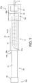
- FIG. 1 shows a side view of a distal portion of a scaffold-balloon catheter assembly 2.
- the catheter assembly 2 includes a catheter shaft 4 and a scaffold 10 crimped to a delivery balloon 12. As shown there are two separate sheaths 20, 30 disposed over the scaffold 10.
- the scaffold 10 is contained within a protecting sheath 20 and a constraining sheath 30, which is slid over the outer surface of the protecting sheath 20 to position it over the scaffold 10.
- both the constraining sheath 30 and protecting sheath 20 are removed by a health professional.
- the sheaths 20, 30 provide an effective radial constraint for reducing recoil in the crimped scaffold 10. Yet the sheaths 20, 30 are also easily removed by a health professional at the time of a medical procedure. A sheath that applies a radial constraint can be difficult to manually remove without adversely affecting the structural integrity of the medical device. In these cases, it is desirable to arrange the sheaths so that special handling is not required by the health professional when the sheath is manually removed. By making the sheath removal process easy to follow or intuitive, the possibility that a health professional will damage the medical device by improperly removing the sheath is reduced.
- the constraint imposed by the sheaths 20, 30 maintain the scaffold 10 at essentially the same, or close to the same diameter it had when removed from the crimping mechanism, i.e., the crimped crossing profile, which is needed for traversing tortuous vessels to deliver the scaffold 10 to a target location in a body.
- the sheath 30 is tightly fit over the sheath 20 and scaffold 10 so that the radial inward force applied on the scaffold 10 can reduce recoil in the scaffold 10.
- the health professional may then remove both sheaths at the time of the medical procedure. As such, any potential recoil in the scaffold 10 prior to using the medical device is minimized.
- the constraining sheath 30 is located over the section of the protecting sheath 20 where the crimped scaffold 10 is found.
- This sheath 30 is made from a polymer tube material having a thickness and pre-stressed inner diameter size suitably chosen to cause the sheath 30 to apply a radially inward directed force on the scaffold 10. The thicker the tube and the smaller the pre-stressed inner diameter size for the sheath 30 the higher this constraint will be on the scaffold 10. However, the sheath 30 thickness should not be too thick, nor its inner diameter too small as this will make it difficult to slide the sheath 30 over, or remove the sheath 30 from the scaffold 10. If excessive force is needed to reposition the sheath 30, the scaffold 10 can dislodge from the balloon 12 or become damaged when the sheath 30 is moved.
- the sheath 20 serves to protect the integrity of the scaffold-balloon structure as the sheath 30 is repositioned relative to the scaffold 10.
- the protecting sheath 20 extends over the entire length of the scaffold (as shown) and beyond the distal tip 6 of the catheter, for reasons that will become apparent.
- the protecting sheath 20 is preferably formed from a unitary piece of polymer material, which is shaped to form differently sized portions 22, 24 and 25 for protecting the scaffold/balloon 10/12.
- a raised end 22 in the form of a cylinder section having a larger diameter than the body portion 21 of the sheath 20 to the right of end 22 which covers the scaffold 10 in FIG. 1 .
- raised end 22 provides an abutting surface with respect to distal movement of sheath 30, i.e., end 30b of sheath 30 abuts end 22 when sheath 30 is moved to the left in FIG. 1 .
- End 22 may alternatively take the shape of a cone with the largest diameter end of the cone being the most distal end of the sheath 20.
- the raised end 22 is used to remove the sheaths 20, 30, as explained below.
- the protecting sheath 20 has a cut 26, extending from the proximal end 20a to a location about at the distal the tip 6 of the catheter assembly 2.
- the cut 26 forms an upper and lower separable halve 28, 29 of the sheath 20. These halves 29, 28 are configured to freely move apart when the sheath 30 is positioned towards the distal end 20b.
- the location 26a may be thought of as a living hinge 26a about which the upper half 29 and lower half 28 of the sheath 20 can rotate, or deflect away from the scaffold 10.
- halves 28, 29 will tend to open up naturally, due to the preload applied by sheath 30 near hinge 26a (the separable halves 28, 29 can be more clearly seen in FIGS. 2A-2D ).
- This arrangement for halves 29, 28 allows sheath 20 it to be easily removed from the scaffold 10 with minimal disruption to scaffold-balloon structural integrity, after sheath 30 is moved to distal end 20b.
- the presence of the halves 28, 29 prevent direct contact between the sliding sheath 30 and the surface of the scaffold 10.
- portions 24 and 25 formed when the combined proximal ends of halves 28, 29 are brought together as in FIG. 1 .
- the portions 24 and 25 take the form of a stepped or notched portion 25 and a raised end 24 similar to end 22, as shown in FIG. 1 and the cross-sectional view of the proximal end 20a of the assembly of FIG. 1A .
- the notched or stepped portion 25 has an outer diameter less than the outer diameter of the portion 21 of the sheath that covers the scaffold 10, as well as the outer diameter of the scaffold/balloon 10/12.
- the raised end 24 has a diameter that is greater than the body portion 21.
- the raised end 24 provides an abutment or stop 24a preventing the proximal end 30a of the sheath 30 from moving to the right in FIG. 1 . As such, the end 24 prevents the sheath 30 from sliding off of the scaffold 10.
- the portion 24 also serves to identify the approximate location of the sheath 30 proximal end 30a so that it is fitted over the scaffold 10 and balloon 12.
- Sheath 30 has a length about equal to the length of the portion 25 plus the scaffold/balloon length so that when end 30a abuts end 24 the sheath 30 will properly cover the entire scaffold/balloon 10/12 length.
- FIG. 1A shows the distal end 20a with the sheath 30 (shown in phantom) replaced by the inwardly directed preload F30 it applies to sheath portion 21 when positioned over the scaffold 10.
- a distal end of portion 25 forms a ledge 25a.
- the inwardly directed preload F30 applied to sheath portion 21 urges the halves 29, 28 together.
- the scaffold/balloon proximal end 14a blocks movement of the sheath 20 to the left in FIG. 1A by interfering with the movement of the ledge 25a to the left.
- the first sheath 30 is moved to the distal end 20b of the sheath 20 (thereby removing the preload F30 ) so that the halves 28, 29 freely open up to allow the ledge 25a to easily pass over the scaffold 10 so that sheath 20 is removed without resistance.
- the user is thereby informed that the sheath 20 is removed properly when there is no resistance to removing the sheath 20 from the balloon-catheter assembly 2.
- This length beyond the distal end 6 facilitates an intuitive sliding removal or attachment of the sheath 30 from / to the scaffold 10 by respectively sliding the sheath 30 along the sheath 20 extension that is distal of tip 6 of the catheter assembly 2.
- the length of the sheath 20 that extends beyond the distal end 4 of the catheter assembly 2 may depend on the choice of sheaths used.
- the sheath 20 is more stiff (e.g., higher wall thickness and/or modulus) relative to the sheath 30 then the length beyond distal end 4 for sheath 20 may be longer so that the halves 28, 29 sheath 20 can be more safely displaced from the scaffold 10 by clearing the sheath 30 more distally of the scaffold 10. If the sheath 30 wall thickness and/or modulus is higher relative to sheath 20 than the length may be shorter since the sheath 30 will tend to naturally open up the halves 28, 29 as it is moved distally of the tip 6.
- a thicker or higher modulus sheath 20 and/or sheath 30 may be desirable to increase the resistance to improper removal of sheath 20, e.g., as when a user attempts to remove sheath 20 with, or before removing sheath 30 from the scaffold 10 (as discussed earlier).
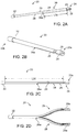
- FIG. 2A shows the sheath 20 with the sheath 30.
- sheath 30 is sized to have a length L30 such that sheath 30 applies a sufficiently uniform radial inward force or preload on the scaffold 10 when end 30a abuts end 24a.
- the length L30 should therefore be slightly greater than the length of the scaffold-balloon structure.
- the sheath 30 can be slid towards or away from the scaffold location (i.e., its location in FIG. 2A or FIG. 1 ) over the sheath outer surface 20.
- FIG. 2D is a perspective view of the upper and lower halves 28, 29 separated from each other. As can be appreciated from this view, the halves 28, 29 rotate about the hinge 26a when they separate.
- FIGS. 2B and 2C show an additional side and perspective view, respectively, of the sheath 20 showing the aforementioned structure, including the portions of notched or stepped portion 25 and end 24 discussed earlier.
- the length L20 in FIG. 2C should be chosen to extend over the scaffold 10 length as well as a sufficient distance beyond the scaffold 10 so that the sheath 30 can be pushed onto the scaffold 10, and removed from the scaffold 10 while the halves 28, 29 are disposed over the scaffold 10.
- sheath 30 thickness and/or inner diameter size is selected with the sheath 20 in mind. That is, the sizing of one can determine what sizing to use for the other, based on achieving an appropriate balance among the amount of pre-load F30 ( FIG.
- the ease in which the sheath 30 can be placed over or removed from the scaffold 10 location increasing resistance to improper removal of sheath 20 (ledge 25a abutting proximal end 14a, as discussed above) and avoiding disruption to the integrity of the scaffold-balloon structure, e.g., pulling the scaffold 10 off the balloon when the sheath 30 is being removed.
- the sheath 30 will impose a higher localized pre-load on the scaffold 10.
- the scaffold 10 is more likely to be affected by sheath 30 movement because the sheath 20 easily deforms under the movement of the sheath 30.
- the scaffold 10 will not be as affected by movement of the sheath 30. And local changes in pre-load on the scaffold 10 will tend to be lower since the sheath 20 does not deform as easily under the movement of the sheath 30.
- the scaffold 10 is crimped to the balloon 12 of the catheter assembly 2 using a crimping mechanism.
- the diameter reduction during crimping may be 2:1, 2.5:1, 3:1, 4:1 or higher. This diameter reduction introduces high stresses in the scaffold structure.
- the memory in the material following crimping causes recoil of the scaffold structure, as discussed earlier.
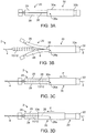
- the sheath pair shown in FIG. 3A , is placed on a mandrel 8 before being attached to the catheter assembly 2.
- the mandrel 8 is passed through the catheter shaft 4 guidewire lumen (not shown), and exits at the distal end 6 of the catheter assembly 2.
- the sheath pair is then placed on the mandrel 8 distally of the catheter assembly 2.
- the mandrel 8 is then used to guide the sheath pair over the scaffold-balloon 10/12 as illustrated in FIGS. 3B-3D .
- the distal end 30a of the sheath 30 is adjacent to the raised end 22 of the sheath 20.
- the halves 28, 29 can freely open or close.
- the sheath pair is then brought towards the scaffold-balloon 10/12.
- the halves 28, 29 easily deflect over the scaffold-balloon 10/12.
- the sheath pair may be slid towards the scaffold-balloon 10/12 as follows. Holding the catheter assembly 2 stationary, grasping the mandrel 8 with one hand and the sheath pair with the other hand and sliding the sheath pair over the mandrel 8 until the halves 28, 29 are located over the scaffold-balloon 10/12 as shown in FIG. 3C .
- the portions 24, 25 are positioned with respect to proximal end 14a as shown in FIG. 1A .
- the constraining sheath 30 can be pushed over the scaffold-balloon 10/12 (as indicated in FIGS. 3C-3D by P).
- the sheath 30 may be pushed over the scaffold-balloon 10/12 in the following manner.
- the raised end 22 and mandrel 8 are grasped with one hand to hold the two stationary.
- the sheath 30 is pushed over the scaffold-balloon 10/12 until the end 30a of sheath 30 is disposed adjacent to, or abuts the raised end 24 of the sheath 20, which indicates the proximate location of the proximal end 14a of the balloon-scaffold 10/12.
- the portion 24 and catheter shaft 4 may be simultaneously held with on hand, while the sheath 30 is pushed towards the scaffold 10 with the other hand.
- the halves 28, 29 are held in place relative to the scaffold 10 while the sheath 30 is being pushed over the scaffold 10.
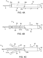
- FIG. 4A depicts the arrangement of the sheaths 20, 30 at the distal end of the catheter assembly 2 when the packaged and sterile medical device is received by a health professional. Examples of such sterile packaging is found in U.S. patent publication no. US 2008-0010947 (docket no. 62571.60).
- the sheath 20 extends well-beyond the distal end 6 of the catheter 2 assembly such that it overhangs the distal end 6.
- FIGS. 4B-4C methods for removing the sheath pair from the scaffold-balloon 10/12 by the health professional are now described. These illustrations refer to moving the sheath pair over the mandrel 8; however, a mandrel 8 is not necessary. The sheath pair may be safely removed from the catheter assembly 2 without using a mandrel 8.
- a sterilized and packaged catheter assembly with sheaths 20, 30 positioned as shown in 4A typically includes the stiffening mandrel 8 in the catheter shaft 4 lumen to provide bending stiffness for shaft 4.
- a distal end of the mandrel 8 has a curled end, or an extension / stop at the distal end (not shown), which is used to manually withdraw the mandrel 8 from the catheter shaft 4 lumen by pulling the mandrel 8 towards the distal end 6 of the catheter assembly 2.
- the sheaths 20, 30 are removed.
- the proscribed steps preferably also include the act of removing the mandrel 8 from the catheter shaft lumen by, e.g., simultaneously gripping the raised end 22, sheath 30 and mandrel 8.
- the sheath 30 is pulled away from the scaffold-balloon 10/12 structure, where it is shown positioned in FIG. 4A .
- the sheath 30 may be withdrawn or pulled away from the scaffold-balloon 10/12 in the following manner.
- One hand grasps the raised end 22 and mandrel 8, to hold the two stationary, while the other hand grasps and pulls the sheath 30 towards the raised end 22.
- the sheath 30 reaches the raised end 22 the halves 28, 29 should freely deflect away from the scaffold 10 surface, since a majority if not all of the cut 26 is to the left of the sheath 30 ( FIG. 4B ).
- both sheaths 20, 30 can be simultaneously pulled away from the scaffold-balloon 10/12.
- the sheaths 20, 30 may be removed by grasping the catheter assembly distal portion, e.g., the catheter shaft 4, and optionally portion 24 as well with one hand and grasping and pulling the sheath 30 distally of the catheter assembly 2 with the other hand.
- the sheath 30 has abutted the raised end 22 (and removing hand from portion 24, if being gripped with shaft 4)
- continued pulling on the sheath 30 distally can safely remove both sheaths without risk of dislodging the scaffold 10 from the balloon.
- the pulling of the sheath 30 distally, while it abuts the raised end 22, causes both the sheath 20 and the sheath 30 to be removed from the scaffold-balloon 10/12.
- the raised end 22 therefore functions as an abutment for removing both sheaths in a safe manner with minimal disruption to the crimped scaffold.
- This final pulling away of the sheath 20 from scaffold 10 may also simultaneously remove the stiffening mandrel 8 from the catheter shaft 4 lumen.
- the assembly of sheaths 20, 30 discourages a health professional from removing the sheath 20 before sheath 30 is moved to end 22.
- a health professional were to pull on the end 22 while the sheath 30 is positioned over the scaffold, the ledges 25a abutting proximal end 14a will interfere with distal movement of the sheath ( FIG. 1A ). When this resistance is felt, this should indicate to the health professional that the sheath 20 is being removed in an improper manner. If the sheath 30 is first moved to end 22, then the sheath 20 can be pulled off of the catheter distal end 6 very easily since the halves 29, 28 (free of the preload F30) will easily open up and pass over the scaffold 10.
- sheath 200 there is illustrated an alternative embodiment of the sheath 20, which will be referred to as sheath 200.
- This sheath has raised abutments or surfaces 224, 222 formed at the distal and proximal ends of sheath 200. Otherwise the sheath 200 has the same construction as sheath 20.
- the raised end 224 forms proximal ends of halves 228, 229. And the sheath 200 has the cut 226 and hinge point 226a.
- the proximal abutment 224 is shown in a frontal view in FIG. 5B .
- the abutment 224 may take the form of a cross having ends 225a, 225b, 225c and 225d.
- the ends 225 form raised abutment surfaces that prevent or resist the sheath 30 from being moved to the left of the sheath 200 when the two are positioned over the scaffold.
- the sheath 30 may slip proximally of the scaffold 10, thereby removing the constraint on the scaffold.
- the same type of abutment 222 may also be formed at the distal end.
- the raised ends 222, 224 may be formed after the sheaths 20, 30 have been positioned over the scaffold-balloon 10/12 structure using, e.g., a hand crimper.
- the hand crimper is applied at the location 224 to form the cross members 225 ( FIG. 5B ) and also at the distal end of sheath 200 a similar structure 222.
Description
- The present invention relates to drug-eluting medical devices; more particularly, the invention relates to sheaths for polymeric scaffolds crimped to a delivery balloon.
- A variety of non-surgical interventional procedures have been developed over the years for opening stenosed or occluded blood vessels in a patient caused by the build up of plaque or other substances on the walls of the blood vessel. Such procedures usually involve the percutaneous introduction of an interventional device into the lumen of the artery. In one procedure the stenosis can be treated by placing an expandable interventional device such as an expandable stent into the stenosed region to hold open and sometimes expand the segment of blood vessel or other arterial lumen. Metal or metal alloy stents have been found useful in the treatment or repair of blood vessels after a stenosis has been compressed by percutaneous transluminal coronary angioplasty (PTCA), percutaneous transluminal angioplasty (PTA) or removal by other means. Metal stents are typically delivered in a compressed condition to the target site, then deployed at the target into an expanded condition or deployed state to support the vessel.
- The following terminology is used. When reference is made to a "stent", this term will refer to a metal or metal alloy structure, generally speaking, while a scaffold will refer to a polymer structure. It is understood, however, that the art sometimes uses the term "stent" when referring to either a metal or polymer structure.
- Metal stents have traditionally fallen into two general categories - balloon expanded and self-expanding. The later type expands to a deployed or expanded state within a vessel when a radial restraint is removed, while the former relies on an externally-applied force to configure it from a crimped or stowed state to the deployed or expanded state.
- For example, self-expanding stents formed from, for example, shape memory metals or super-elastic nickel-titanum (NiTi) alloys are designed to automatically expand from a compressed state when the stent is advanced out of a distal end of the delivery catheter into the body lumen, i.e. when the radial restraint is withdrawn or removed. Typically, these stents are delivered within a radially restraining polymer sheath. The sheath maintains the low profile needed to navigate the stent towards the target site. Once at the target site, the sheath is then removed or withdrawn in a controlled manner to facilitate deployment or placement at the desired examples. Examples of self-expanding stents constrained within a sheath when delivered to a target site within a body are found in
US 6254609 ,US 20030004561 andUS 20020052640 . - Balloon expanded stents, as the name implies, are expanded upon application of an external force through inflation of a balloon, upon which the stent is crimped. The expanding balloon applies a radial outward force on the luminal surfaces of the stent. During the expansion from a crimped or stowed, to deployed or expanded state the stent undergoes a plastic or irreversible deformation in the sense that the stent will essentially maintain its deformed, deployed state after balloon pressure is withdrawn.
- Balloon expanded stents may also be disposed within a sheath, either during a transluminal delivery to a target site or during the assembly of the stent-balloon catheter delivery system. The balloon expanded stent may be contained within a sheath when delivered to a target site to minimize dislodgment of the stent from the balloon while en route to the target vessel. Sheaths may also be used to protect a drug eluting stent during a crimping process, which presses or crimps the stent to the balloon catheter. When an iris-type crimping mechanism, for example, is used to crimp a stent to balloon, the blades of the crimper, often hardened metal, can form gouges in a drug-polymer coating or even strip off coating such as when the blades and/or stent struts are misaligned during the diameter reduction. Examples of stents that utilize a sheath to protect the stent during a crimping process are found in
US 6783542 andUS 6805703 . - A polymer scaffold, such as that described in
US 20100004735 may be made from a biodegradable, bioabsorbable, bioresorbable, or bioerodable polymer. The terms biodegradable, bioabsorbable, bioresorbable, biosoluble or bioerodable refer to the property of a material or stent to degrade, absorb, resorb, or erode away after the scaffold has been implanted at the target vessel. The polymer scaffold described inUS 2010/0004735 , as opposed to a metal stent, is intended to remain in the body for only a limited period of time. In many treatment applications, the presence of a stent in a body may be necessary for a limited period of time until its intended function of, for example, maintaining vascular patency and/or drug delivery is accomplished. Moreover, it is believed that biodegradable scaffolds, as opposed to a metal stent, allow for improved healing of the anatomical lumen and reduced incidence of late stent thrombosis. In these cases, there is a desire to treat a vessel using a polymer scaffold, in particular a bioerodible polymer scaffold, as opposed to a metal stent, so that the prosthesis's presence in the vessel is for a limited duration. However, there are numerous challenges to overcome when developing a delivery system having a polymer scaffold. - Polymer material considered for use as a polymeric scaffold, e.g. poly(L-lactide) ("PLLA"), poly(L-lactide-co-glycolide) ("PLGA"), poly(D-lactide-co-glycolide) or poly(L-lactide-co-D-lactide) ("PLLA-co-PDLA") with less than 10% D-lactide, and PLLD/PDLA stereo complex, may be described, through comparison with a metallic material used to form a stent, in some of the following ways. A suitable polymer has a low strength to weight ratio, which means more material is needed to provide an equivalent mechanical property to that of a metal. Therefore, struts must be made thicker and wider to have the required strength for a stent to support lumen walls at a desired radius. The scaffold made from such polymers also tends to be brittle or have limited fracture toughness. The anisotropic and rate-dependant inelastic properties (i.e., strength / stiffness of the material varies depending upon the rate at which the material is deformed) inherent in the material only compound this complexity in working with a polymer, particularly, bio-absorbable polymer such as PLLA or PLGA. Challenges faced when securing a polymer scaffold to a delivery balloon are discussed in
U.S. Patent Application Serial No. 12/861,719 (Attorney docket 62571.448). - When using a polymer scaffold, several of the accepted processes for metal stent handling can no longer be used. A metal stent may be crimped to a balloon in such a manner as to minimize, if not eliminate recoil in the metal structure after removal from the crimp head. Metal materials used for stents are generally capable of being worked more during the crimping process than polymer materials. This desirable property of the metal allows for less concern over the metal stent - balloon engagement changing over time when the stent-catheter is packaged and awaiting use in a medical procedure. Due to the material's ability to be worked during the crimping process, e.g., successively crimped and released at high temperatures within the crimp mechanism, any propensity for elastic recoil in the material following crimping can be significantly reduced, if not eliminated, without affecting the stent's radial strength when later expanded by the balloon. As such, following a crimping process the stent-catheter assembly often does not need packaging or treatment to maintain the desired stent-balloon engagement and delivery profile. If the stent were to recoil to a larger diameter, meaning elastically expand to a larger diameter after the crimping forces are withdrawn, then significant dislodgment force could be lost and the stent-balloon profile not maintained at the desired diameter needed to deliver the stent to the target site.
- While a polymer scaffold may be formed so that it is capable of being crimped in such a manner as to reduce inherent elastic recoil tendencies in the material when crimped, e.g., by maintaining crimping blades on the scaffold surface for an appreciable dwell period, the effectiveness of these methods are limited. Significantly, the material generally is incapable of being worked to the degree that a metal stent may be worked without introducing deployed strength problems, such as excessive cracking in the material. Recoil of the crimped structure, therefore, is a problem that needs to be addressed
WO02060345A2 -
WO9839056A2 - In view of the foregoing, there is a need to address the challenges associated with securing a polymer scaffold to a delivery balloon and maintaining the integrity of a scaffold-balloon catheter delivery system up until the time when the scaffold and balloon are delivered to a target site within a body.
- The invention is defined as in claim 1: There is an apparatus, comprising a scaffold crimped to a balloon of a catheter, the catheter having a distal end and the scaffold being crimped to the balloon proximally of the distal end; a first sheath disposed over the scaffold, the first sheath including an extension distal of the catheter distal end and a portion forming an interfering ledge disposed proximal to the scaffold; and a second sheath disposed over the scaffold and first sheath, the second sheath applying a preload to the scaffold and the first sheath to maintain contact between the first sheath and scaffold; wherein the first sheath is removable from the scaffold only after the second sheath has been moved to the distal extension such that the interfering ledge is capable of deflecting away from the scaffold only when the second sheath is removed from the scaffold; and wherein the apparatus is configured as a medical device suitable for being introduced into a patient when the first and second sheaths are removed from the catheter.
-
-
FIG. 1 is a side view of a polymer scaffold-balloon catheter assembly (medical device) with a pair of sheaths placed over the crimped scaffold. -
FIG. 1A shows a side view cross-section of a portion of the device ofFIG. 1 at a proximal end thereof. -
FIG. 2A is a perspective view of the sheath pair ofFIG. 1 . -
FIGS. 2B-2D show a side view, and first and perspective views of a protecting sheath of the sheath pair ofFIG. 2A . -
FIGS. 3A-3D illustrate a method of securing the sheath pair ofFIG. 2A to a distal end of the catheter assembly ofFIG. 1 . -
FIGS. 4A-4C illustrate a method of removing the sheath pair ofFIG. 2A from the distal end of the catheter assembly ofFIG. 1 . -
FIGS. 5A-5B illustrate side and front views of an alternative embodiment of a protecting sheath. - A polymer scaffold according to a preferred embodiment is formed from a radially expanded, or biaxially expanded extruded PLLA tube. The scaffold is laser cut from the expanded tube. The diameter of the tube is preferably selected to be about the same, or larger than the intended deployed diameter for the scaffold to provided desirable radial strength characteristics, as explained earlier. The scaffold is then crimped onto the balloon of the balloon catheter. Preferably, an iris-type crimper is used to crimp the scaffold to the balloon. The desired crimped profile for the scaffold is ½ or less than ½ of the starting (pre crimp) diameter of the expanded tube and scaffold. In the embodiments the ratio of the starting diameter (before crimping) to the final crimp diameter may be 2:1, 2.5:1, 3:1, or higher. For example, the ratio of starting diameter to final crimped diameter may be greater than the ratio of the deployed diameter to the final crimped diameter of the scaffold, e.g., from about 4:1 to 6:1.
- The pre-crimp memory in the scaffold material following crimping will induce some recoil when the scaffold is removed from the crimper. While a dwell period within the crimper can reduce this recoil tendency, it is found that there is residual recoil that needs to be restrained while the scaffold is awaiting use. This is done by placing a restraining sheath over the scaffold immediately after the crimper blades are released and the scaffold removed from the crimper head. This need to reduce recoil is particularly evident when the diameter reduction during crimping is high, since for a larger starting diameter compared to the crimped diameter the crimped material can have higher recoil tendencies. Examples of polymers that may be used to construct sheaths described herein are Pebax, PTFE, Polyethelene, Polycarbonate, Polymide and Nylon. Examples of restraining sheaths for polymer scaffold, and methods for attaching and removing restraining sheaths for polymer scaffold are described in
U.S. application no. 12/916,349 (docket no. 104584.7). -
FIG. 1 shows a side view of a distal portion of a scaffold-balloon catheter assembly 2. Thecatheter assembly 2 includes acatheter shaft 4 and a scaffold 10 crimped to a delivery balloon 12. As shown there are twoseparate sheaths sheath 20 and a constrainingsheath 30, which is slid over the outer surface of the protectingsheath 20 to position it over the scaffold 10. Before inserting thecatheter assembly 2 distal end within a patient, both the constrainingsheath 30 and protectingsheath 20 are removed by a health professional. - The
sheaths sheaths - The constraint imposed by the
sheaths sheath 30 is tightly fit over thesheath 20 and scaffold 10 so that the radial inward force applied on the scaffold 10 can reduce recoil in the scaffold 10. The health professional may then remove both sheaths at the time of the medical procedure. As such, any potential recoil in the scaffold 10 prior to using the medical device is minimized. - The
sheath 30, although imposing a tight fit on the scaffold 10 (through sheath 30), can be easily removed by a health professional without risk of the scaffold 10 being accidentally pulled off of the balloon 12. This is accomplished by the manner in which thesheath 20 is positioned and removed from the scaffold 10. If there are excessive pulling forces on the scaffold 10 when sheaths are removed, the scaffold 10 may dislodge from a balloon 12, or shift on the balloon 12, thereby reducing scaffold-balloon engagement relied on to hold the scaffold 10 to the balloon 12. - When the scaffold 10 is constrained by
sheath 30, as inFIG. 1 , the constrainingsheath 30 is located over the section of the protectingsheath 20 where the crimped scaffold 10 is found. Thissheath 30 is made from a polymer tube material having a thickness and pre-stressed inner diameter size suitably chosen to cause thesheath 30 to apply a radially inward directed force on the scaffold 10. The thicker the tube and the smaller the pre-stressed inner diameter size for thesheath 30 the higher this constraint will be on the scaffold 10. However, thesheath 30 thickness should not be too thick, nor its inner diameter too small as this will make it difficult to slide thesheath 30 over, or remove thesheath 30 from the scaffold 10. If excessive force is needed to reposition thesheath 30, the scaffold 10 can dislodge from the balloon 12 or become damaged when thesheath 30 is moved. - If only the
single sheath 30 were used to constrain the scaffold 10, i.e., thesheath 20 is not present, the amount of preload that thesheath 30 could apply to the scaffold 10 without affecting scaffold-balloon engagement would be limited. However, by introducing the protectingsheath 20 between the scaffold-balloon surface andsheath 30 thesheath 30 can impose a higher preload on the scaffold 10 without risk to the integrity of the scaffold-balloon engagement when thesheath 30 is applied to and/or removed from the scaffold 10. The protectingsheath 20 therefore serves to protect the integrity of the scaffold-balloon structure as thesheath 30 is repositioned relative to the scaffold 10. - The protecting
sheath 20 extends over the entire length of the scaffold (as shown) and beyond the distal tip 6 of the catheter, for reasons that will become apparent. The protectingsheath 20 is preferably formed from a unitary piece of polymer material, which is shaped to form differentlysized portions - At the
distal end 20b ofsheath 20 there is a raisedend 22 in the form of a cylinder section having a larger diameter than thebody portion 21 of thesheath 20 to the right ofend 22 which covers the scaffold 10 inFIG. 1 . As such, raisedend 22 provides an abutting surface with respect to distal movement ofsheath 30, i.e.,end 30b ofsheath 30 abuts end 22 whensheath 30 is moved to the left inFIG. 1 .End 22 may alternatively take the shape of a cone with the largest diameter end of the cone being the most distal end of thesheath 20. The raisedend 22 is used to remove thesheaths - The protecting
sheath 20 has acut 26, extending from theproximal end 20a to a location about at the distal the tip 6 of thecatheter assembly 2. Thecut 26 forms an upper and lowerseparable halve sheath 20. Thesehalves sheath 30 is positioned towards thedistal end 20b. Thelocation 26a may be thought of as aliving hinge 26a about which theupper half 29 andlower half 28 of thesheath 20 can rotate, or deflect away from the scaffold 10. Whensheath 30 is moved distally of the scaffold 10 inFIG. 1 , thehalves sheath 30 nearhinge 26a (theseparable halves FIGS. 2A-2D ). This arrangement forhalves sheath 20 it to be easily removed from the scaffold 10 with minimal disruption to scaffold-balloon structural integrity, aftersheath 30 is moved todistal end 20b. Whensheath 30 is being fitted over the scaffold 10 or removed from the scaffold 10, the presence of thehalves sheath 30 and the surface of the scaffold 10. - At a
proximal end 20a ofsheath 20 there areportions halves FIG. 1 . When thehalves portions portion 25 and a raisedend 24 similar to end 22, as shown inFIG. 1 and the cross-sectional view of theproximal end 20a of the assembly ofFIG. 1A . The notched or steppedportion 25 has an outer diameter less than the outer diameter of theportion 21 of the sheath that covers the scaffold 10, as well as the outer diameter of the scaffold/balloon 10/12. The raisedend 24 has a diameter that is greater than thebody portion 21. The raisedend 24 provides an abutment or stop 24a preventing theproximal end 30a of thesheath 30 from moving to the right inFIG. 1 . As such, theend 24 prevents thesheath 30 from sliding off of the scaffold 10. Theportion 24 also serves to identify the approximate location of thesheath 30proximal end 30a so that it is fitted over the scaffold 10 and balloon 12.Sheath 30 has a length about equal to the length of theportion 25 plus the scaffold/balloon length so that whenend 30a abutsend 24 thesheath 30 will properly cover the entire scaffold/balloon 10/12 length. -
Portion 25 discourages removal of thesheath 20 prior to removal ofsheath 30 from the scaffold 10.FIG. 1A shows thedistal end 20a with the sheath 30 (shown in phantom) replaced by the inwardly directed preload F30 it applies tosheath portion 21 when positioned over the scaffold 10. A distal end ofportion 25 forms aledge 25a. Whensheath 30 is positioned over the scaffold 10 the inwardly directed preload F30 applied tosheath portion 21 urges thehalves halves proximal end 14a blocks movement of thesheath 20 to the left inFIG. 1A by interfering with the movement of theledge 25a to the left. Thus, if a user attempts to pull thesheath 20 off prior to removing thesheath 30 from the scaffold 10 area (which can damage the scaffold/balloon integrity), there will be resistance to this movement due to theledges 25a abutting the balloonproximal end 14a (theledge 25a thus may be thought of as an interference or interfering ledge part of the sheath 20). This resistance should indicate to the user that thesheaths sheaths first sheath 30 is moved to thedistal end 20b of the sheath 20 (thereby removing the preload F30) so that thehalves ledge 25a to easily pass over the scaffold 10 so thatsheath 20 is removed without resistance. The user is thereby informed that thesheath 20 is removed properly when there is no resistance to removing thesheath 20 from the balloon-catheter assembly 2. - Thus, scaffold-balloon integrity is protected by the presence of the
halves portion 25, as discussed above. The extended length ofsheath 20, beyond the tip 6, e.g., is about equal to a length of the scaffold 10, the length of thesheath 30 or greater than both. This length beyond the distal end 6 facilitates an intuitive sliding removal or attachment of thesheath 30 from / to the scaffold 10 by respectively sliding thesheath 30 along thesheath 20 extension that is distal of tip 6 of thecatheter assembly 2. The length of thesheath 20 that extends beyond thedistal end 4 of the catheter assembly 2 (length L21 inFIG. 4A ) may depend on the choice of sheaths used. For example, from the perspective of the health professional removal process, if thesheath 20 is more stiff (e.g., higher wall thickness and/or modulus) relative to thesheath 30 then the length beyonddistal end 4 forsheath 20 may be longer so that thehalves sheath 20 can be more safely displaced from the scaffold 10 by clearing thesheath 30 more distally of the scaffold 10. If thesheath 30 wall thickness and/or modulus is higher relative tosheath 20 than the length may be shorter since thesheath 30 will tend to naturally open up thehalves higher modulus sheath 20 and/orsheath 30 may be desirable to increase the resistance to improper removal ofsheath 20, e.g., as when a user attempts to removesheath 20 with, or before removingsheath 30 from the scaffold 10 (as discussed earlier). - Referring to
FIGS. 2B-2D , there are shown various views of thesheath 20.FIG. 2A shows thesheath 20 with thesheath 30. As mentioned abovesheath 30 is sized to have a length L30 such thatsheath 30 applies a sufficiently uniform radial inward force or preload on the scaffold 10 whenend 30a abutsend 24a. The length L30 should therefore be slightly greater than the length of the scaffold-balloon structure. Thesheath 30 can be slid towards or away from the scaffold location (i.e., its location inFIG. 2A orFIG. 1 ) over the sheathouter surface 20. As noted earlier, thesheath 20 has separable upper andlower halves cut 26 made across thetube forming sheath 20.FIG. 2D is a perspective view of the upper andlower halves halves hinge 26a when they separate.FIGS. 2B and 2C show an additional side and perspective view, respectively, of thesheath 20 showing the aforementioned structure, including the portions of notched or steppedportion 25 and end 24 discussed earlier. - The length L20 in
FIG. 2C should be chosen to extend over the scaffold 10 length as well as a sufficient distance beyond the scaffold 10 so that thesheath 30 can be pushed onto the scaffold 10, and removed from the scaffold 10 while thehalves sheath 30, i.e., L20 = 2* L30, to achieve this purpose. This length should be sufficient to allow the upper andlower halves living hinge 26a and freely away from the scaffold surface (as inFIG. 2D ) without interference from thesheath 30. - As mentioned earlier, a thicker tube and smaller inner diameter for
sheath 30 will cause thesheath 30 to apply a greater pre-load on the scaffold 10. Thesheath 30 thickness and/or inner diameter size is selected with thesheath 20 in mind. That is, the sizing of one can determine what sizing to use for the other, based on achieving an appropriate balance among the amount of pre-load F30 (FIG. 1A ) desired, the ease in which thesheath 30 can be placed over or removed from the scaffold 10 location, increasing resistance to improper removal of sheath 20 (ledge 25a abuttingproximal end 14a, as discussed above) and avoiding disruption to the integrity of the scaffold-balloon structure, e.g., pulling the scaffold 10 off the balloon when thesheath 30 is being removed. For example, if a relatively thin and/or low modulus tube is used for sheath 20 (as compared to sheath 30), thesheath 30 will impose a higher localized pre-load on the scaffold 10. And the scaffold 10 is more likely to be affected bysheath 30 movement because thesheath 20 easily deforms under the movement of thesheath 30. If thesheath 20 is made thick and /or a higher modulus tube material is used for sheath 20 (compared to sheath 30) the scaffold 10 will not be as affected by movement of thesheath 30. And local changes in pre-load on the scaffold 10 will tend to be lower since thesheath 20 does not deform as easily under the movement of thesheath 30. - Referring to
FIGS. 3A-3D , methods of assembly using thesheaths 20, 30 (sheath pair) are now described. The scaffold 10 is crimped to the balloon 12 of thecatheter assembly 2 using a crimping mechanism. As noted above, for a polymer scaffold the diameter reduction during crimping may be 2:1, 2.5:1, 3:1, 4:1 or higher. This diameter reduction introduces high stresses in the scaffold structure. The memory in the material following crimping causes recoil of the scaffold structure, as discussed earlier. - One can incorporate lengthy dwell times within the crimper, e.g., after the final crimp step, to allow stress-relaxation to occur in the structure while heated crimper blades are maintaining a fixed diameter and temperature to facilitate stress relaxation. Both the dwell period and the disposing of a constraining sheath over the crimped scaffold after crimping helps to reduce recoil after crimping. Crimping of the scaffold 10 to the balloon 12 including desirable dwell times and temperatures that can affect stress relaxation and recoil after crimping are disclosed in
U.S. patent application no. 12/861,719 (docket no. 62571.448),U.S. patent application no. 13/089,225 (docket no. 62571.517) andU.S. patent application no. 13/107,666 (docket no. 62571.522). - The sheath pair, shown in
FIG. 3A , is placed on amandrel 8 before being attached to thecatheter assembly 2. Themandrel 8 is passed through thecatheter shaft 4 guidewire lumen (not shown), and exits at the distal end 6 of thecatheter assembly 2. The sheath pair is then placed on themandrel 8 distally of thecatheter assembly 2. Themandrel 8 is then used to guide the sheath pair over the scaffold-balloon 10/12 as illustrated inFIGS. 3B-3D . - Referring to
FIG. 3B , thedistal end 30a of thesheath 30 is adjacent to the raisedend 22 of thesheath 20. In this configuration thehalves halves catheter assembly 2 stationary, grasping themandrel 8 with one hand and the sheath pair with the other hand and sliding the sheath pair over themandrel 8 until thehalves FIG. 3C . When properly positioned, theportions proximal end 14a as shown inFIG. 1A . - Referring to
FIGS. 3C-3D , once thehalves sheath 30 can be pushed over the scaffold-balloon 10/12 (as indicated inFIGS. 3C-3D by P). Thesheath 30 may be pushed over the scaffold-balloon 10/12 in the following manner. The raisedend 22 andmandrel 8 are grasped with one hand to hold the two stationary. Then, using the other hand thesheath 30 is pushed over the scaffold-balloon 10/12 until theend 30a ofsheath 30 is disposed adjacent to, or abuts the raisedend 24 of thesheath 20, which indicates the proximate location of theproximal end 14a of the balloon-scaffold 10/12. Alternatively, theportion 24 andcatheter shaft 4 may be simultaneously held with on hand, while thesheath 30 is pushed towards the scaffold 10 with the other hand. By grasping theportion 24 with thecatheter shaft 4, thehalves sheath 30 is being pushed over the scaffold 10. - The
catheter assembly 2 with sheaths arranged as inFIG. 4A is packaged and sterilized. At the time when the catheter assembly is to be used in a medical procedure the package is opened and the sheath pair removed from the distal end. Thecatheter assembly 2 is not configured for being introduced into the patient until the sheath pair is removed.FIGS. 1 ,1A and4A depict the arrangement of thesheaths catheter assembly 2 when the packaged and sterile medical device is received by a health professional. Examples of such sterile packaging is found in U.S. patent publication no.US 2008-0010947 (docket no. 62571.60). Thesheath 20 extends well-beyond the distal end 6 of thecatheter 2 assembly such that it overhangs the distal end 6. The overhanging portion of thesheath 20, which has a length of more than L21 (FIG. 4A ), is provided to facilitate a safe and intuitive removal of the sheath pair by a health professional, thereby reducing the chances that the sheath pair are removed improperly. - Referring to
FIGS. 4B-4C , methods for removing the sheath pair from the scaffold-balloon 10/12 by the health professional are now described. These illustrations refer to moving the sheath pair over themandrel 8; however, amandrel 8 is not necessary. The sheath pair may be safely removed from thecatheter assembly 2 without using amandrel 8. - A sterilized and packaged catheter assembly with
sheaths mandrel 8 in thecatheter shaft 4 lumen to provide bending stiffness forshaft 4. A distal end of themandrel 8 has a curled end, or an extension / stop at the distal end (not shown), which is used to manually withdraw themandrel 8 from thecatheter shaft 4 lumen by pulling themandrel 8 towards the distal end 6 of thecatheter assembly 2. In the following example thesheaths mandrel 8 from the catheter shaft lumen by, e.g., simultaneously gripping the raisedend 22,sheath 30 andmandrel 8. - First, the
sheath 30 is pulled away from the scaffold-balloon 10/12 structure, where it is shown positioned inFIG. 4A . Thesheath 30 may be withdrawn or pulled away from the scaffold-balloon 10/12 in the following manner. One hand grasps the raisedend 22 andmandrel 8, to hold the two stationary, while the other hand grasps and pulls thesheath 30 towards the raisedend 22. When thesheath 30 reaches the raisedend 22 thehalves cut 26 is to the left of the sheath 30 (FIG. 4B ). At this point bothsheaths - As an alternative, the
sheaths catheter shaft 4, andoptionally portion 24 as well with one hand and grasping and pulling thesheath 30 distally of thecatheter assembly 2 with the other hand. Once thesheath 30 has abutted the raised end 22 (and removing hand fromportion 24, if being gripped with shaft 4), continued pulling on thesheath 30 distally can safely remove both sheaths without risk of dislodging the scaffold 10 from the balloon. The pulling of thesheath 30 distally, while it abuts the raisedend 22, causes both thesheath 20 and thesheath 30 to be removed from the scaffold-balloon 10/12. The raisedend 22 therefore functions as an abutment for removing both sheaths in a safe manner with minimal disruption to the crimped scaffold. This final pulling away of thesheath 20 from scaffold 10 may also simultaneously remove thestiffening mandrel 8 from thecatheter shaft 4 lumen. - As discussed earlier, the assembly of
sheaths sheath 20 beforesheath 30 is moved to end 22. For example, if a health professional were to pull on theend 22 while thesheath 30 is positioned over the scaffold, theledges 25a abuttingproximal end 14a will interfere with distal movement of the sheath (FIG. 1A ). When this resistance is felt, this should indicate to the health professional that thesheath 20 is being removed in an improper manner. If thesheath 30 is first moved to end 22, then thesheath 20 can be pulled off of the catheter distal end 6 very easily since thehalves 29, 28 (free of the preload F30) will easily open up and pass over the scaffold 10. - Referring to
FIGS. 5A-5B there is illustrated an alternative embodiment of thesheath 20, which will be referred to assheath 200. This sheath has raised abutments orsurfaces sheath 200. Otherwise thesheath 200 has the same construction assheath 20. The raisedend 224 forms proximal ends ofhalves 228, 229. And thesheath 200 has the cut 226 and hinge point 226a. - The
proximal abutment 224 is shown in a frontal view inFIG. 5B . In this view theabutment 224 may take the form of across having ends sheath 30 from being moved to the left of thesheath 200 when the two are positioned over the scaffold. For example, when the packaged catheter assembly is being transported to a medical facility, thesheath 30 may slip proximally of the scaffold 10, thereby removing the constraint on the scaffold. By placing the abutment 225 at the proximal end of thesheath 200, thesheath 30 cannot move proximally. The same type ofabutment 222 may also be formed at the distal end. - In a method of assembly the raised ends 222, 224 may be formed after the
sheaths location 224 to form the cross members 225 (FIG. 5B ) and also at the distal end of sheath 200 asimilar structure 222. - The above description of illustrated embodiments of the invention, including what is described in the Abstract, is not intended to be exhaustive or to limit the invention to the precise forms disclosed. While specific embodiments of, and examples for, the invention are described herein for illustrative purposes, various modifications are possible within the scope of the invention, as those skilled in the relevant art will recognize.
- These modifications can be made to the invention in light of the above detailed description. The terms used in the following claims should not be construed to limit the invention to the specific embodiments disclosed in the specification. Rather, the scope of the invention is to be determined entirely by the following claims, which are to be construed in accordance with established doctrines of claim interpretation.
Claims (14)
- An apparatus, comprising:a scaffold (10) crimped to a balloon (12) of a catheter, the catheter having a distal end (6) and the scaffold (10) being crimped to the balloon (12) proximally of the distal end (6);a first or protecting sheath (20) disposed over the scaffold (10); anda second or constraining sheath (30) disposed over the scaffold (10) and first sheath, the second sheath applying a preload to the scaffold (10) and the first sheath to maintain contact between the first sheath and scaffold (10);wherein the apparatus is configured as a medical device suitable for being introduced into a patient when the first and second sheaths are removed from the catheter, andcharacterized in thatthe first sheath includes an extension distal of the catheter distal end (6) and a portion forming an interfering ledge (25a) disposed proximal to the scaffold (10) and wherein the first sheath is removable from the scaffold (10) only after the second sheath has been moved to the distal extension such that the interfering ledge (25a) is capable of deflecting away from the scaffold (10) only when the second sheath is removed from the scaffold (10).
- The apparatus of Claim 1, wherein the first sheath extends distally of the catheter distal end (6) by about a length equal to the length of the scaffold (10).
- The apparatus of Claim 2, wherein the first sheath (30) includes a first and second separable half forming a proximal portion of the first sheath (30).
- The apparatus of Claim 2, the first sheath having a total length that is a sum of a first length and a second length, the first length is about the length of the scaffold (10) and the second length is equal to or greater than the first length, wherein the second length is about equal to the amount the first sheath extends distally of the distal end (6).
- The apparatus of Claim 4, wherein a first portion of the first sheath (30) disposed over the first length comprises a cut forming halves of the protecting sheath (20) and a second portion of the first sheath (30) disposed over the second length is substantially devoid of the cut.
- The apparatus of Claim 5, wherein the second portion of the first sheath (30) includes a raised portion at its distal (4) and proximal (20a) ends.
- The apparatus of Claim 1, wherein the protecting sheath (20) extends distally of the distal end (6) by at least the length of the scaffold (10).
- The apparatus of Claim 7, wherein the first sheath (30) extends distally of the distal end (6) by more than the length of the scaffold (10).
- The apparatus of Claim 1, wherein the first sheath (20) includes an abutment having an extent capable of preventing the second sheath (30) from being disposed proximally of the proximal end (20a) of the scaffold (10) and balloon (12).
- The apparatus of Claim 9, wherein the abutment comprises a crimped portion of the first sheath (20).
- The apparatus of Claim 1, wherein
the first sheath (30) and second sheath are arranged relative to each other such that the apparatus is capable of being configured into a medical device suitable for being introduced into a patient by (a) pulling the second sheath distally along the first sheath (30) outer surface such that the second sheath is displaced to a location substantially distal of the scaffold (10) or the catheter distal end (6), and (b) after the first sheath (30) has been moved to the substantially distal location, removing the first sheath (30) from the scaffold (10) by pulling the second sheath against the first sheath (30) extension, thereby displacing the first sheath (30) distally with the second sheath. - The apparatus of Claim 11, the catheter having a shaft (4) and the shaft (4) having
a lumen, further including
a mandrel (8) disposed within the shaft lumen;
wherein the mandrel (8), first sheath (30) and second sheath are arranged relative to each other such that the apparatus is capable of being configured into a medical device suitable for being introduced into a patient by simultaneously removing the mandrel (8) from the lumen and the first sheath (30) from the scaffold (10) by pulling the second sheath against the first sheath (30) extension while gripping the mandrel (8), thereby displacing the first sheath (30) distally with the second sheath and removing the mandrel (8) from the catheter shaft (4) lumen. - The apparatus of Claim 1, wherein the first sheath (30) includes an upper (29) and lower (28) half which together form the interfering ledge (25a).
- The apparatus of Claim 13, wherein the first sheath (30) includes a raised portion proximal of the interfering ledge (25a).
Priority Applications (1)
| Application Number | Priority Date | Filing Date | Title |
|---|---|---|---|
| EP17159927.7A EP3205366A1 (en) | 2011-05-27 | 2012-05-25 | Polymer scaffold sheaths |
Applications Claiming Priority (2)
| Application Number | Priority Date | Filing Date | Title |
|---|---|---|---|
| US13/118,311 US8414528B2 (en) | 2011-05-27 | 2011-05-27 | Polymer scaffold sheaths |
| PCT/US2012/039719 WO2012166661A1 (en) | 2011-05-27 | 2012-05-25 | Polymer scaffold sheaths |
Related Child Applications (1)
| Application Number | Title | Priority Date | Filing Date |
|---|---|---|---|
| EP17159927.7A Division EP3205366A1 (en) | 2011-05-27 | 2012-05-25 | Polymer scaffold sheaths |
Publications (2)
| Publication Number | Publication Date |
|---|---|
| EP2714171A1 EP2714171A1 (en) | 2014-04-09 |
| EP2714171B1 true EP2714171B1 (en) | 2017-03-15 |
Family
ID=46201883
Family Applications (2)
| Application Number | Title | Priority Date | Filing Date |
|---|---|---|---|
| EP12725274.0A Not-in-force EP2714171B1 (en) | 2011-05-27 | 2012-05-25 | Polymer scaffold sheaths |
| EP17159927.7A Withdrawn EP3205366A1 (en) | 2011-05-27 | 2012-05-25 | Polymer scaffold sheaths |
Family Applications After (1)
| Application Number | Title | Priority Date | Filing Date |
|---|---|---|---|
| EP17159927.7A Withdrawn EP3205366A1 (en) | 2011-05-27 | 2012-05-25 | Polymer scaffold sheaths |
Country Status (5)
| Country | Link |
|---|---|
| US (3) | US8414528B2 (en) |
| EP (2) | EP2714171B1 (en) |
| JP (1) | JP5979738B2 (en) |
| CN (2) | CN105919700B (en) |
| WO (1) | WO2012166661A1 (en) |
Families Citing this family (34)
| Publication number | Priority date | Publication date | Assignee | Title |
|---|---|---|---|---|
| GB0815339D0 (en) * | 2008-08-21 | 2008-10-01 | Angiomed Ag | Method of loading a stent into a sheath |
| CA2720466A1 (en) * | 2008-05-09 | 2009-11-12 | Juergen Dorn | Method of loading a stent into a sheath |
| US8414528B2 (en) | 2011-05-27 | 2013-04-09 | Abbott Cardiovascular Systems Inc. | Polymer scaffold sheaths |
| US8852257B2 (en) | 2011-06-21 | 2014-10-07 | Abbott Cardiovascular Systems Inc. | Sheaths used with polymer scaffold |
| US9517150B2 (en) | 2012-10-23 | 2016-12-13 | Abbott Cardiovascular Systems Inc. | Time-dependent polymer scaffolds |
| US9072590B2 (en) | 2012-12-07 | 2015-07-07 | Abbott Cardiovascular Systems Inc. | Sheaths reducing recoil and loss of retention for polymer scaffolds crimped to balloons |
| US9078740B2 (en) | 2013-01-21 | 2015-07-14 | Howmedica Osteonics Corp. | Instrumentation and method for positioning and securing a graft |
| US9662231B2 (en) | 2013-03-15 | 2017-05-30 | Abbott Cardiovascular Systems Inc. | Polymer scaffolds having enhanced axial fatigue properties |
| JP2016516552A (en) * | 2013-05-03 | 2016-06-09 | シー・アール・バード・インコーポレーテッドC R Bard Incorporated | Protective sheath that can be peeled off |
| US10039656B2 (en) | 2013-06-05 | 2018-08-07 | Abbott Cardiovascular Systems Inc. | Coupled scaffold segments |
| US9788983B2 (en) | 2013-06-21 | 2017-10-17 | Abbott Cardiovascular Systems Inc. | Removable sheath assembly for a polymer scaffold |
| US9675483B2 (en) | 2013-06-21 | 2017-06-13 | Abbott Cardiovascular Systems Inc. | Protective sheath assembly for a polymer scaffold |
| US10245145B2 (en) * | 2013-09-16 | 2019-04-02 | Symetis Sa | Method and apparatus for compressing/loading stent-valves |
| US10098771B2 (en) | 2013-09-25 | 2018-10-16 | Abbott Cardiovascular Systems Inc. | Clip sheath for a polymer scaffold |
| US9913958B2 (en) | 2014-02-28 | 2018-03-13 | Abbott Cardiovascular Systems Inc. | Protective sheaths for medical devices |
| US9364361B2 (en) * | 2014-03-13 | 2016-06-14 | Abbott Cardiovascular Systems Inc. | Striped sheaths for medical devices |
| US9795497B2 (en) | 2014-09-18 | 2017-10-24 | Abbott Cardiovascular Systems Inc. | Thermal processing of polymer scaffolds |
| US10569063B2 (en) | 2014-10-03 | 2020-02-25 | W. L. Gore & Associates, Inc. | Removable covers for drug eluting medical devices |
| US10080675B2 (en) | 2015-08-24 | 2018-09-25 | Abbott Cardiovascular Systems Inc. | System and method for conditioning an endoprosthesis |
| CN107488345B (en) * | 2016-06-12 | 2020-08-25 | 上海微创医疗器械(集团)有限公司 | Device, stent binding device and stent binding method |
| WO2017215427A1 (en) * | 2016-06-12 | 2017-12-21 | 上海微创医疗器械(集团)有限公司 | Restriction apparatus, stent system, and method for using restriction apparatus |
| CN108113783B (en) * | 2016-11-28 | 2019-11-26 | 上海微创医疗器械(集团)有限公司 | Protective device and its manufacturing method, the medical device of bracket |
| US10537450B2 (en) * | 2016-12-29 | 2020-01-21 | Boston Scientific Scimed, Inc. | Method for loading a stent into a delivery device |
| JP6949546B2 (en) * | 2017-04-28 | 2021-10-13 | 川澄化学工業株式会社 | Transport catheter and intravascular indwelling device transport device |
| JP7103721B2 (en) * | 2017-06-05 | 2022-07-20 | Sbカワスミ株式会社 | Transport catheter and intravascular indwelling device transport device |
| US10682492B2 (en) | 2018-01-19 | 2020-06-16 | Medtronic Vascular, Inc. | Expandable balloon sheath |
| US10737071B2 (en) | 2018-01-19 | 2020-08-11 | Medtronic, Inc. | Splittable sheath |
| US10702673B2 (en) | 2018-01-19 | 2020-07-07 | Medtronic Vascular, Inc. | Expandable balloon sheaths |
| US10688287B2 (en) | 2018-01-19 | 2020-06-23 | Medtronic, Inc. | Sheath including sheath body and sheath insert |
| US10668255B2 (en) | 2018-01-19 | 2020-06-02 | Medtronic Vascular, Inc. | Sheath for medically expandable balloon |
| CN110123497A (en) * | 2018-02-02 | 2019-08-16 | 上海微创医疗器械(集团)有限公司 | The protective device and medical device of bracket |
| US11389627B1 (en) | 2018-10-02 | 2022-07-19 | Lutonix Inc. | Balloon protectors, balloon-catheter assemblies, and methods thereof |
| US20200129164A1 (en) * | 2018-10-24 | 2020-04-30 | M-V Arterica AB | Self-expanding hemostatic devices and methods for fascia and vessel passages |
| EP4061244A1 (en) | 2019-11-19 | 2022-09-28 | Arterica Inc. | Vascular closure devices and methods |
Family Cites Families (93)
| Publication number | Priority date | Publication date | Assignee | Title |
|---|---|---|---|---|
| US4243050A (en) | 1977-12-13 | 1981-01-06 | Littleford Philip O | Method for inserting pacemaker electrodes and the like |
| US4581025A (en) | 1983-11-14 | 1986-04-08 | Cook Incorporated | Sheath |
| US4710181A (en) | 1985-06-11 | 1987-12-01 | Genus Catheter Technologies, Inc. | Variable diameter catheter |
| US4846811A (en) | 1987-01-29 | 1989-07-11 | International Medical Innovators, Inc. | Sliding sheath for medical needles |
| US5015231A (en) | 1989-04-21 | 1991-05-14 | Scimed Life Systems, Inc. | Multipart split sleeve balloon protector for dilatation catheter |
| DE4018525C2 (en) | 1990-06-09 | 1994-05-05 | Kaltenbach Martin | Expandable area catheter |
| CA2060067A1 (en) | 1991-01-28 | 1992-07-29 | Lilip Lau | Stent delivery system |
| US5158545A (en) | 1991-05-02 | 1992-10-27 | Brigham And Women's Hospital | Diameter expansion cannula |
| US5386817A (en) | 1991-06-10 | 1995-02-07 | Endomedical Technologies, Inc. | Endoscope sheath and valve system |
| US5935122A (en) | 1991-12-13 | 1999-08-10 | Endovascular Technologies, Inc. | Dual valve, flexible expandable sheath and method |
| US5395349A (en) | 1991-12-13 | 1995-03-07 | Endovascular Technologies, Inc. | Dual valve reinforced sheath and method |
| US5643175A (en) | 1992-09-01 | 1997-07-01 | Adair; Edwin L. | Sterilizable endoscope with separable disposable tube assembly |
| US5352236A (en) | 1992-09-29 | 1994-10-04 | Medtronic, Inc. | Balloon protector |
| US5250033A (en) | 1992-10-28 | 1993-10-05 | Interventional Thermodynamics, Inc. | Peel-away introducer sheath having proximal fitting |
| US5458615A (en) | 1993-07-06 | 1995-10-17 | Advanced Cardiovascular Systems, Inc. | Stent delivery system |
| KR970004845Y1 (en) | 1993-09-27 | 1997-05-21 | 주식회사 수호메디테크 | Stent for expanding a lumen |
| CA2160022C (en) | 1994-02-07 | 2005-01-18 | Keiji Igaki | Stent device and stent supplying system |
| EP0688545B1 (en) | 1994-06-17 | 2002-09-18 | Terumo Kabushiki Kaisha | Method for manufacturing an indwelling stent |
| US5569294A (en) | 1994-09-26 | 1996-10-29 | Medtronic, Inc. | Two piece balloon protector |
| US5765682A (en) | 1994-10-13 | 1998-06-16 | Menlo Care, Inc. | Restrictive package for expandable or shape memory medical devices and method of preventing premature change of same |
| US5591226A (en) * | 1995-01-23 | 1997-01-07 | Schneider (Usa) Inc. | Percutaneous stent-graft and method for delivery thereof |
| US5647857A (en) | 1995-03-16 | 1997-07-15 | Endotex Interventional Systems, Inc. | Protective intraluminal sheath |
| US5788707A (en) | 1995-06-07 | 1998-08-04 | Scimed Life Systems, Inc. | Pull back sleeve system with compression resistant inner shaft |
| US5776141A (en) | 1995-08-28 | 1998-07-07 | Localmed, Inc. | Method and apparatus for intraluminal prosthesis delivery |
| GB9518400D0 (en) | 1995-09-08 | 1995-11-08 | Anson Medical Ltd | A surgical graft/stent system |
| DE69508592T2 (en) | 1995-11-14 | 1999-09-16 | Schneider Europ Gmbh | Stent implantation device |
| US5693066A (en) | 1995-12-21 | 1997-12-02 | Medtronic, Inc. | Stent mounting and transfer device and method |
| US5749852A (en) | 1996-07-23 | 1998-05-12 | Medtronic, Inc. | Sheath system for autoperfusion dilatation catheter balloon |
| US5868707A (en) | 1996-08-15 | 1999-02-09 | Advanced Cardiovascular Systems, Inc. | Protective sheath for catheter balloons |
| US5800517A (en) | 1996-08-19 | 1998-09-01 | Scimed Life Systems, Inc. | Stent delivery system with storage sleeve |
| EP1011520B1 (en) * | 1996-09-18 | 2003-11-19 | Micro Therapeutics, Inc. | Intracranial stent |
| US6254628B1 (en) | 1996-12-09 | 2001-07-03 | Micro Therapeutics, Inc. | Intracranial stent |
| US6010529A (en) | 1996-12-03 | 2000-01-04 | Atrium Medical Corporation | Expandable shielded vessel support |
| US5893868A (en) | 1997-03-05 | 1999-04-13 | Scimed Life Systems, Inc. | Catheter with removable balloon protector and stent delivery system with removable stent protector |
| US6152944A (en) * | 1997-03-05 | 2000-11-28 | Scimed Life Systems, Inc. | Catheter with removable balloon protector and stent delivery system with removable stent protector |
| US5992000A (en) | 1997-10-16 | 1999-11-30 | Scimed Life Systems, Inc. | Stent crimper |
| IE980241A1 (en) | 1998-04-02 | 1999-10-20 | Salviac Ltd | Delivery catheter with split sheath |
| US6110146A (en) | 1998-09-30 | 2000-08-29 | Medtronic Ave, Inc. | Protector for catheter balloon with guidewire backloading system |
| US6544278B1 (en) | 1998-11-06 | 2003-04-08 | Scimed Life Systems, Inc. | Rolling membrane stent delivery system |
| US6254609B1 (en) | 1999-01-11 | 2001-07-03 | Scimed Life Systems, Inc. | Self-expanding stent delivery system with two sheaths |
| NL1012527C2 (en) | 1999-07-06 | 2001-01-09 | Cordis Europ | Balloon catheter with tear line. |
| US6533806B1 (en) | 1999-10-01 | 2003-03-18 | Scimed Life Systems, Inc. | Balloon yielded delivery system and endovascular graft design for easy deployment |
| JP2001175745A (en) | 1999-12-21 | 2001-06-29 | Matsushita Electric Ind Co Ltd | System and method for electronic commercial transaction |
| US6629992B2 (en) | 2000-08-04 | 2003-10-07 | Advanced Cardiovascular Systems, Inc. | Sheath for self-expanding stent |
| US6899727B2 (en) | 2001-01-22 | 2005-05-31 | Gore Enterprise Holdings, Inc. | Deployment system for intraluminal devices |
| US6783542B2 (en) | 2001-02-22 | 2004-08-31 | Scimed Life Systems, Inc | Crimpable balloon/stent protector |
| US20030004561A1 (en) | 2001-06-28 | 2003-01-02 | Steve Bigus | Peeling sheath for self-expanding stent |
| US6749584B2 (en) * | 2001-08-17 | 2004-06-15 | Reva Medical, Inc. | Balloon protector sleeve |
| US6805703B2 (en) | 2001-09-18 | 2004-10-19 | Scimed Life Systems, Inc. | Protective membrane for reconfiguring a workpiece |
| US6790224B2 (en) | 2002-02-04 | 2004-09-14 | Scimed Life Systems, Inc. | Medical devices |
| US6939327B2 (en) | 2002-05-07 | 2005-09-06 | Cardiac Pacemakers, Inc. | Peel-away sheath |
| WO2003101347A1 (en) | 2002-05-31 | 2003-12-11 | Wilson-Cook Medical Inc. | Stent introducer apparatus |
| MXPA05003238A (en) | 2002-09-26 | 2005-09-12 | Endovascular Devices Inc | Apparatus and method for delivery of mitomycin through an eluting biocompatible implantable medical device. |
| US7105013B2 (en) * | 2002-09-30 | 2006-09-12 | Advanced Cardiovascular Systems, Inc. | Protective sleeve assembly for a balloon catheter |
| US7753945B2 (en) | 2003-01-17 | 2010-07-13 | Gore Enterprise Holdings, Inc. | Deployment system for an endoluminal device |
| US7198636B2 (en) | 2003-01-17 | 2007-04-03 | Gore Enterprise Holdings, Inc. | Deployment system for an endoluminal device |
| US20050118344A1 (en) | 2003-12-01 | 2005-06-02 | Pacetti Stephen D. | Temperature controlled crimping |
| CA2542368A1 (en) * | 2003-10-15 | 2005-04-28 | Kabushikikaisha Igaki Iryo Sekkei | Device for delivery of stent for vessel |
| US20050288766A1 (en) | 2004-06-28 | 2005-12-29 | Xtent, Inc. | Devices and methods for controlling expandable prostheses during deployment |
| US8308789B2 (en) * | 2004-07-16 | 2012-11-13 | W. L. Gore & Associates, Inc. | Deployment system for intraluminal devices |
| US7765670B2 (en) | 2004-08-13 | 2010-08-03 | Boston Scientific Scimed, Inc. | Method to simultaneously load and cover self expanding stents |
| US7347868B2 (en) | 2004-10-26 | 2008-03-25 | Baronova, Inc. | Medical device delivery catheter |
| US7918880B2 (en) | 2005-02-16 | 2011-04-05 | Boston Scientific Scimed, Inc. | Self-expanding stent and delivery system |
| US20070061001A1 (en) | 2005-09-13 | 2007-03-15 | Advanced Cardiovascular Systems, Inc. | Packaging sheath for drug coated stent |
| US20070208408A1 (en) | 2006-03-06 | 2007-09-06 | Boston Scientific Scimed, Inc. | Non-foreshortening sheaths and assemblies for use |
| US8333000B2 (en) | 2006-06-19 | 2012-12-18 | Advanced Cardiovascular Systems, Inc. | Methods for improving stent retention on a balloon catheter |
| US7998404B2 (en) | 2006-07-13 | 2011-08-16 | Advanced Cardiovascular Systems, Inc. | Reduced temperature sterilization of stents |
| US7886419B2 (en) | 2006-07-18 | 2011-02-15 | Advanced Cardiovascular Systems, Inc. | Stent crimping apparatus and method |
| US8439961B2 (en) * | 2006-07-31 | 2013-05-14 | Boston Scientific Scimed, Inc. | Stent retaining mechanisms |
| US20080269865A1 (en) * | 2006-08-07 | 2008-10-30 | Xtent, Inc. | Custom Length Stent Apparatus |
| US8388673B2 (en) | 2008-05-02 | 2013-03-05 | Abbott Cardiovascular Systems Inc. | Polymeric stent |
| US20080319388A1 (en) * | 2007-06-21 | 2008-12-25 | David Slattery | Device delivery system with balloon-relative sheath positioning |
| US8046897B2 (en) | 2007-09-28 | 2011-11-01 | Abbott Cardiovascular Systems Inc. | Method and apparatus for stent retention on a balloon catheter |
| DE102008011688A1 (en) * | 2008-02-28 | 2009-09-10 | Osypka, Peter, Dr. Ing. | Insertion sleeve for an introducer kit |
| US8545544B2 (en) | 2008-04-03 | 2013-10-01 | Gardia Medical Ltd. | Delivery catheter with constraining sheath and methods of deploying medical devices into a body lumen |
| US8123793B2 (en) | 2008-09-10 | 2012-02-28 | Boston Scientific Scimed, Inc. | Pre-crimp balloon inflation |
| CN201379671Y (en) * | 2009-01-19 | 2010-01-13 | 加奇生物科技(上海)有限公司 | Conveyer for retractable self-elastic brain nerve scaffold |
| US20110184509A1 (en) * | 2010-01-27 | 2011-07-28 | Abbott Laboratories | Dual sheath assembly and method of use |
| US20110208292A1 (en) | 2010-02-19 | 2011-08-25 | Abbott Laboratories | Hinged sheath assembly and method of use |
| US8752261B2 (en) | 2010-07-07 | 2014-06-17 | Abbott Cardiovascular Systems Inc. | Mounting stents on stent delivery systems |
| US8539663B2 (en) * | 2010-08-23 | 2013-09-24 | Abbott Cardiovascular Systems Inc. | Reducing crimping damage to polymer scaffold |
| US10111767B2 (en) * | 2010-10-29 | 2018-10-30 | Abbott Cardiovascular Systems Inc. | Sheaths used in polymer scaffold delivery systems |
| US8961848B2 (en) | 2011-04-18 | 2015-02-24 | Abbott Cardiovascular Systems Inc. | Methods for increasing a retention force between a polymeric scaffold and a delivery balloon |
| US8752265B2 (en) | 2011-05-13 | 2014-06-17 | Abbott Cardiovascular Systems Inc. | Methods for crimping a polymeric scaffold to a delivery balloon and achieving stable mechanical properties in the scaffold after crimping |
| US8414528B2 (en) | 2011-05-27 | 2013-04-09 | Abbott Cardiovascular Systems Inc. | Polymer scaffold sheaths |
| US8852257B2 (en) | 2011-06-21 | 2014-10-07 | Abbott Cardiovascular Systems Inc. | Sheaths used with polymer scaffold |
| JP2013188252A (en) | 2012-03-12 | 2013-09-26 | Terumo Corp | Stent delivery system and balloon catheter system |
| US9072590B2 (en) | 2012-12-07 | 2015-07-07 | Abbott Cardiovascular Systems Inc. | Sheaths reducing recoil and loss of retention for polymer scaffolds crimped to balloons |
| US9788983B2 (en) | 2013-06-21 | 2017-10-17 | Abbott Cardiovascular Systems Inc. | Removable sheath assembly for a polymer scaffold |
| US9675483B2 (en) | 2013-06-21 | 2017-06-13 | Abbott Cardiovascular Systems Inc. | Protective sheath assembly for a polymer scaffold |
| US10098771B2 (en) | 2013-09-25 | 2018-10-16 | Abbott Cardiovascular Systems Inc. | Clip sheath for a polymer scaffold |
| US9913958B2 (en) | 2014-02-28 | 2018-03-13 | Abbott Cardiovascular Systems Inc. | Protective sheaths for medical devices |
| US9364361B2 (en) | 2014-03-13 | 2016-06-14 | Abbott Cardiovascular Systems Inc. | Striped sheaths for medical devices |
-
2011
- 2011-05-27 US US13/118,311 patent/US8414528B2/en active Active
-
2012
- 2012-05-25 EP EP12725274.0A patent/EP2714171B1/en not_active Not-in-force
- 2012-05-25 EP EP17159927.7A patent/EP3205366A1/en not_active Withdrawn
- 2012-05-25 CN CN201610333770.7A patent/CN105919700B/en not_active Expired - Fee Related
- 2012-05-25 CN CN201280033660.9A patent/CN103826687B/en not_active Expired - Fee Related
- 2012-05-25 WO PCT/US2012/039719 patent/WO2012166661A1/en active Application Filing
- 2012-05-25 JP JP2014512167A patent/JP5979738B2/en not_active Expired - Fee Related
-
2013
- 2013-03-21 US US13/848,683 patent/US9119741B2/en not_active Expired - Fee Related
-
2015
- 2015-08-24 US US14/834,345 patent/US10232147B2/en not_active Expired - Fee Related
Non-Patent Citations (1)
| Title |
|---|
| None * |
Also Published As
| Publication number | Publication date |
|---|---|
| CN105919700A (en) | 2016-09-07 |
| JP2014516708A (en) | 2014-07-17 |
| US9119741B2 (en) | 2015-09-01 |
| EP2714171A1 (en) | 2014-04-09 |
| WO2012166661A1 (en) | 2012-12-06 |
| US10232147B2 (en) | 2019-03-19 |
| CN103826687A (en) | 2014-05-28 |
| JP5979738B2 (en) | 2016-08-31 |
| CN105919700B (en) | 2018-04-06 |
| US20150360006A1 (en) | 2015-12-17 |
| US20130218256A1 (en) | 2013-08-22 |
| US20120302955A1 (en) | 2012-11-29 |
| CN103826687B (en) | 2016-05-25 |
| US8414528B2 (en) | 2013-04-09 |
| EP3205366A1 (en) | 2017-08-16 |
Similar Documents
| Publication | Publication Date | Title |
|---|---|---|
| EP2714171B1 (en) | Polymer scaffold sheaths | |
| US10470907B2 (en) | Sheaths used with polymer scaffolds | |
| US20190110914A1 (en) | Protective sheath assembly for a polymer scaffold | |
| EP3010454B1 (en) | Removable sheath assembly for a polymer scaffold | |
| US9579181B2 (en) | Sheaths reducing recoil and loss of retention for polymer scaffolds crimped to balloons | |
| US10098771B2 (en) | Clip sheath for a polymer scaffold | |
| US10449074B2 (en) | Striped sheaths for medical devices | |
| US10111767B2 (en) | Sheaths used in polymer scaffold delivery systems |
Legal Events
| Date | Code | Title | Description |
|---|---|---|---|
| PUAI | Public reference made under article 153(3) epc to a published international application that has entered the european phase |
Free format text: ORIGINAL CODE: 0009012 |
|
| 17P | Request for examination filed |
Effective date: 20140102 |
|
| AK | Designated contracting states |
Kind code of ref document: A1 Designated state(s): AL AT BE BG CH CY CZ DE DK EE ES FI FR GB GR HR HU IE IS IT LI LT LU LV MC MK MT NL NO PL PT RO RS SE SI SK SM TR |
|
| DAX | Request for extension of the european patent (deleted) | ||
| REG | Reference to a national code |
Ref country code: HK Ref legal event code: DE Ref document number: 1196788 Country of ref document: HK |
|
| GRAP | Despatch of communication of intention to grant a patent |
Free format text: ORIGINAL CODE: EPIDOSNIGR1 |
|
| INTG | Intention to grant announced |
Effective date: 20160930 |
|
| GRAS | Grant fee paid |
Free format text: ORIGINAL CODE: EPIDOSNIGR3 |
|
| GRAA | (expected) grant |
Free format text: ORIGINAL CODE: 0009210 |
|
| AK | Designated contracting states |
Kind code of ref document: B1 Designated state(s): AL AT BE BG CH CY CZ DE DK EE ES FI FR GB GR HR HU IE IS IT LI LT LU LV MC MK MT NL NO PL PT RO RS SE SI SK SM TR |
|
| REG | Reference to a national code |
Ref country code: CH Ref legal event code: EP Ref country code: GB Ref legal event code: FG4D |
|
| REG | Reference to a national code |
Ref country code: IE Ref legal event code: FG4D |
|
| REG | Reference to a national code |
Ref country code: AT Ref legal event code: REF Ref document number: 874929 Country of ref document: AT Kind code of ref document: T Effective date: 20170415 |
|
| REG | Reference to a national code |
Ref country code: FR Ref legal event code: PLFP Year of fee payment: 6 |
|
| REG | Reference to a national code |
Ref country code: DE Ref legal event code: R096 Ref document number: 602012029834 Country of ref document: DE |
|
| REG | Reference to a national code |
Ref country code: NL Ref legal event code: FP |
|
| REG | Reference to a national code |
Ref country code: LT Ref legal event code: MG4D |
|
| PG25 | Lapsed in a contracting state [announced via postgrant information from national office to epo] |
Ref country code: LT Free format text: LAPSE BECAUSE OF FAILURE TO SUBMIT A TRANSLATION OF THE DESCRIPTION OR TO PAY THE FEE WITHIN THE PRESCRIBED TIME-LIMIT Effective date: 20170315 Ref country code: GR Free format text: LAPSE BECAUSE OF FAILURE TO SUBMIT A TRANSLATION OF THE DESCRIPTION OR TO PAY THE FEE WITHIN THE PRESCRIBED TIME-LIMIT Effective date: 20170616 Ref country code: HR Free format text: LAPSE BECAUSE OF FAILURE TO SUBMIT A TRANSLATION OF THE DESCRIPTION OR TO PAY THE FEE WITHIN THE PRESCRIBED TIME-LIMIT Effective date: 20170315 Ref country code: FI Free format text: LAPSE BECAUSE OF FAILURE TO SUBMIT A TRANSLATION OF THE DESCRIPTION OR TO PAY THE FEE WITHIN THE PRESCRIBED TIME-LIMIT Effective date: 20170315 Ref country code: NO Free format text: LAPSE BECAUSE OF FAILURE TO SUBMIT A TRANSLATION OF THE DESCRIPTION OR TO PAY THE FEE WITHIN THE PRESCRIBED TIME-LIMIT Effective date: 20170615 |
|
| REG | Reference to a national code |
Ref country code: AT Ref legal event code: MK05 Ref document number: 874929 Country of ref document: AT Kind code of ref document: T Effective date: 20170315 |
|
| PG25 | Lapsed in a contracting state [announced via postgrant information from national office to epo] |
Ref country code: SE Free format text: LAPSE BECAUSE OF FAILURE TO SUBMIT A TRANSLATION OF THE DESCRIPTION OR TO PAY THE FEE WITHIN THE PRESCRIBED TIME-LIMIT Effective date: 20170315 Ref country code: RS Free format text: LAPSE BECAUSE OF FAILURE TO SUBMIT A TRANSLATION OF THE DESCRIPTION OR TO PAY THE FEE WITHIN THE PRESCRIBED TIME-LIMIT Effective date: 20170315 Ref country code: BG Free format text: LAPSE BECAUSE OF FAILURE TO SUBMIT A TRANSLATION OF THE DESCRIPTION OR TO PAY THE FEE WITHIN THE PRESCRIBED TIME-LIMIT Effective date: 20170615 Ref country code: LU Free format text: LAPSE BECAUSE OF NON-PAYMENT OF DUE FEES Effective date: 20170531 Ref country code: LV Free format text: LAPSE BECAUSE OF FAILURE TO SUBMIT A TRANSLATION OF THE DESCRIPTION OR TO PAY THE FEE WITHIN THE PRESCRIBED TIME-LIMIT Effective date: 20170315 |
|
| PG25 | Lapsed in a contracting state [announced via postgrant information from national office to epo] |
Ref country code: RO Free format text: LAPSE BECAUSE OF FAILURE TO SUBMIT A TRANSLATION OF THE DESCRIPTION OR TO PAY THE FEE WITHIN THE PRESCRIBED TIME-LIMIT Effective date: 20170315 Ref country code: AT Free format text: LAPSE BECAUSE OF FAILURE TO SUBMIT A TRANSLATION OF THE DESCRIPTION OR TO PAY THE FEE WITHIN THE PRESCRIBED TIME-LIMIT Effective date: 20170315 Ref country code: CZ Free format text: LAPSE BECAUSE OF FAILURE TO SUBMIT A TRANSLATION OF THE DESCRIPTION OR TO PAY THE FEE WITHIN THE PRESCRIBED TIME-LIMIT Effective date: 20170315 Ref country code: IT Free format text: LAPSE BECAUSE OF FAILURE TO SUBMIT A TRANSLATION OF THE DESCRIPTION OR TO PAY THE FEE WITHIN THE PRESCRIBED TIME-LIMIT Effective date: 20170315 Ref country code: EE Free format text: LAPSE BECAUSE OF FAILURE TO SUBMIT A TRANSLATION OF THE DESCRIPTION OR TO PAY THE FEE WITHIN THE PRESCRIBED TIME-LIMIT Effective date: 20170315 Ref country code: ES Free format text: LAPSE BECAUSE OF FAILURE TO SUBMIT A TRANSLATION OF THE DESCRIPTION OR TO PAY THE FEE WITHIN THE PRESCRIBED TIME-LIMIT Effective date: 20170315 Ref country code: SK Free format text: LAPSE BECAUSE OF FAILURE TO SUBMIT A TRANSLATION OF THE DESCRIPTION OR TO PAY THE FEE WITHIN THE PRESCRIBED TIME-LIMIT Effective date: 20170315 |
|
| PG25 | Lapsed in a contracting state [announced via postgrant information from national office to epo] |
Ref country code: PL Free format text: LAPSE BECAUSE OF FAILURE TO SUBMIT A TRANSLATION OF THE DESCRIPTION OR TO PAY THE FEE WITHIN THE PRESCRIBED TIME-LIMIT Effective date: 20170315 Ref country code: PT Free format text: LAPSE BECAUSE OF FAILURE TO SUBMIT A TRANSLATION OF THE DESCRIPTION OR TO PAY THE FEE WITHIN THE PRESCRIBED TIME-LIMIT Effective date: 20170717 Ref country code: IS Free format text: LAPSE BECAUSE OF FAILURE TO SUBMIT A TRANSLATION OF THE DESCRIPTION OR TO PAY THE FEE WITHIN THE PRESCRIBED TIME-LIMIT Effective date: 20170715 Ref country code: SM Free format text: LAPSE BECAUSE OF FAILURE TO SUBMIT A TRANSLATION OF THE DESCRIPTION OR TO PAY THE FEE WITHIN THE PRESCRIBED TIME-LIMIT Effective date: 20170315 |
|
| REG | Reference to a national code |
Ref country code: DE Ref legal event code: R097 Ref document number: 602012029834 Country of ref document: DE |
|
| REG | Reference to a national code |
Ref country code: CH Ref legal event code: PL Ref country code: HK Ref legal event code: GR Ref document number: 1196788 Country of ref document: HK |
|
| PLBE | No opposition filed within time limit |
Free format text: ORIGINAL CODE: 0009261 |
|
| STAA | Information on the status of an ep patent application or granted ep patent |
Free format text: STATUS: NO OPPOSITION FILED WITHIN TIME LIMIT |
|
| PG25 | Lapsed in a contracting state [announced via postgrant information from national office to epo] |
Ref country code: MC Free format text: LAPSE BECAUSE OF FAILURE TO SUBMIT A TRANSLATION OF THE DESCRIPTION OR TO PAY THE FEE WITHIN THE PRESCRIBED TIME-LIMIT Effective date: 20170315 Ref country code: DK Free format text: LAPSE BECAUSE OF FAILURE TO SUBMIT A TRANSLATION OF THE DESCRIPTION OR TO PAY THE FEE WITHIN THE PRESCRIBED TIME-LIMIT Effective date: 20170315 |
|
| 26N | No opposition filed |
Effective date: 20171218 |
|
| PG25 | Lapsed in a contracting state [announced via postgrant information from national office to epo] |
Ref country code: LI Free format text: LAPSE BECAUSE OF NON-PAYMENT OF DUE FEES Effective date: 20170531 Ref country code: SI Free format text: LAPSE BECAUSE OF FAILURE TO SUBMIT A TRANSLATION OF THE DESCRIPTION OR TO PAY THE FEE WITHIN THE PRESCRIBED TIME-LIMIT Effective date: 20170315 Ref country code: CH Free format text: LAPSE BECAUSE OF NON-PAYMENT OF DUE FEES Effective date: 20170531 |
|
| PG25 | Lapsed in a contracting state [announced via postgrant information from national office to epo] |
Ref country code: LU Free format text: LAPSE BECAUSE OF NON-PAYMENT OF DUE FEES Effective date: 20170525 |
|
| REG | Reference to a national code |
Ref country code: FR Ref legal event code: PLFP Year of fee payment: 7 |
|
| REG | Reference to a national code |
Ref country code: BE Ref legal event code: MM Effective date: 20170531 |
|
| PG25 | Lapsed in a contracting state [announced via postgrant information from national office to epo] |
Ref country code: BE Free format text: LAPSE BECAUSE OF NON-PAYMENT OF DUE FEES Effective date: 20170531 |
|
| PG25 | Lapsed in a contracting state [announced via postgrant information from national office to epo] |
Ref country code: MT Free format text: LAPSE BECAUSE OF NON-PAYMENT OF DUE FEES Effective date: 20170525 |
|
| PG25 | Lapsed in a contracting state [announced via postgrant information from national office to epo] |
Ref country code: HU Free format text: LAPSE BECAUSE OF FAILURE TO SUBMIT A TRANSLATION OF THE DESCRIPTION OR TO PAY THE FEE WITHIN THE PRESCRIBED TIME-LIMIT; INVALID AB INITIO Effective date: 20120525 |
|
| PGFP | Annual fee paid to national office [announced via postgrant information from national office to epo] |
Ref country code: FR Payment date: 20190417 Year of fee payment: 8 |
|
| PG25 | Lapsed in a contracting state [announced via postgrant information from national office to epo] |
Ref country code: CY Free format text: LAPSE BECAUSE OF NON-PAYMENT OF DUE FEES Effective date: 20170315 |
|
| PG25 | Lapsed in a contracting state [announced via postgrant information from national office to epo] |
Ref country code: MK Free format text: LAPSE BECAUSE OF FAILURE TO SUBMIT A TRANSLATION OF THE DESCRIPTION OR TO PAY THE FEE WITHIN THE PRESCRIBED TIME-LIMIT Effective date: 20170315 |
|
| PG25 | Lapsed in a contracting state [announced via postgrant information from national office to epo] |
Ref country code: TR Free format text: LAPSE BECAUSE OF FAILURE TO SUBMIT A TRANSLATION OF THE DESCRIPTION OR TO PAY THE FEE WITHIN THE PRESCRIBED TIME-LIMIT Effective date: 20170315 |
|
| PG25 | Lapsed in a contracting state [announced via postgrant information from national office to epo] |
Ref country code: AL Free format text: LAPSE BECAUSE OF FAILURE TO SUBMIT A TRANSLATION OF THE DESCRIPTION OR TO PAY THE FEE WITHIN THE PRESCRIBED TIME-LIMIT Effective date: 20170315 |
|
| PGFP | Annual fee paid to national office [announced via postgrant information from national office to epo] |
Ref country code: NL Payment date: 20200421 Year of fee payment: 9 Ref country code: DE Payment date: 20200417 Year of fee payment: 9 Ref country code: IE Payment date: 20200429 Year of fee payment: 9 |
|
| PGFP | Annual fee paid to national office [announced via postgrant information from national office to epo] |
Ref country code: GB Payment date: 20200429 Year of fee payment: 9 |
|
| PG25 | Lapsed in a contracting state [announced via postgrant information from national office to epo] |
Ref country code: FR Free format text: LAPSE BECAUSE OF NON-PAYMENT OF DUE FEES Effective date: 20200531 |
|
| REG | Reference to a national code |
Ref country code: DE Ref legal event code: R119 Ref document number: 602012029834 Country of ref document: DE |
|
| REG | Reference to a national code |
Ref country code: NL Ref legal event code: MM Effective date: 20210601 |
|
| GBPC | Gb: european patent ceased through non-payment of renewal fee |
Effective date: 20210525 |
|
| PG25 | Lapsed in a contracting state [announced via postgrant information from national office to epo] |
Ref country code: IE Free format text: LAPSE BECAUSE OF NON-PAYMENT OF DUE FEES Effective date: 20210525 Ref country code: GB Free format text: LAPSE BECAUSE OF NON-PAYMENT OF DUE FEES Effective date: 20210525 Ref country code: DE Free format text: LAPSE BECAUSE OF NON-PAYMENT OF DUE FEES Effective date: 20211201 |
|
| PG25 | Lapsed in a contracting state [announced via postgrant information from national office to epo] |
Ref country code: NL Free format text: LAPSE BECAUSE OF NON-PAYMENT OF DUE FEES Effective date: 20210601 |