EP2714331B1 - Polishing pad with homogeneous body having discrete protrusions thereon - Google Patents
Polishing pad with homogeneous body having discrete protrusions thereon Download PDFInfo
- Publication number
- EP2714331B1 EP2714331B1 EP12723065.4A EP12723065A EP2714331B1 EP 2714331 B1 EP2714331 B1 EP 2714331B1 EP 12723065 A EP12723065 A EP 12723065A EP 2714331 B1 EP2714331 B1 EP 2714331B1
- Authority
- EP
- European Patent Office
- Prior art keywords
- homogeneous body
- polishing
- polishing pad
- protrusions
- hardness
- Prior art date
- Legal status (The legal status is an assumption and is not a legal conclusion. Google has not performed a legal analysis and makes no representation as to the accuracy of the status listed.)
- Active
Links
Images


Classifications
-
- B—PERFORMING OPERATIONS; TRANSPORTING
- B24—GRINDING; POLISHING
- B24B—MACHINES, DEVICES, OR PROCESSES FOR GRINDING OR POLISHING; DRESSING OR CONDITIONING OF ABRADING SURFACES; FEEDING OF GRINDING, POLISHING, OR LAPPING AGENTS
- B24B37/00—Lapping machines or devices; Accessories
- B24B37/11—Lapping tools
- B24B37/20—Lapping pads for working plane surfaces
- B24B37/26—Lapping pads for working plane surfaces characterised by the shape of the lapping pad surface, e.g. grooved
-
- H—ELECTRICITY
- H01—ELECTRIC ELEMENTS
- H01L—SEMICONDUCTOR DEVICES NOT COVERED BY CLASS H10
- H01L21/00—Processes or apparatus adapted for the manufacture or treatment of semiconductor or solid state devices or of parts thereof
- H01L21/02—Manufacture or treatment of semiconductor devices or of parts thereof
- H01L21/04—Manufacture or treatment of semiconductor devices or of parts thereof the devices having at least one potential-jump barrier or surface barrier, e.g. PN junction, depletion layer or carrier concentration layer
- H01L21/18—Manufacture or treatment of semiconductor devices or of parts thereof the devices having at least one potential-jump barrier or surface barrier, e.g. PN junction, depletion layer or carrier concentration layer the devices having semiconductor bodies comprising elements of Group IV of the Periodic System or AIIIBV compounds with or without impurities, e.g. doping materials
- H01L21/30—Treatment of semiconductor bodies using processes or apparatus not provided for in groups H01L21/20 - H01L21/26
- H01L21/302—Treatment of semiconductor bodies using processes or apparatus not provided for in groups H01L21/20 - H01L21/26 to change their surface-physical characteristics or shape, e.g. etching, polishing, cutting
- H01L21/304—Mechanical treatment, e.g. grinding, polishing, cutting
-
- B—PERFORMING OPERATIONS; TRANSPORTING
- B24—GRINDING; POLISHING
- B24B—MACHINES, DEVICES, OR PROCESSES FOR GRINDING OR POLISHING; DRESSING OR CONDITIONING OF ABRADING SURFACES; FEEDING OF GRINDING, POLISHING, OR LAPPING AGENTS
- B24B37/00—Lapping machines or devices; Accessories
- B24B37/11—Lapping tools
- B24B37/20—Lapping pads for working plane surfaces
- B24B37/205—Lapping pads for working plane surfaces provided with a window for inspecting the surface of the work being lapped
-
- B—PERFORMING OPERATIONS; TRANSPORTING
- B24—GRINDING; POLISHING
- B24B—MACHINES, DEVICES, OR PROCESSES FOR GRINDING OR POLISHING; DRESSING OR CONDITIONING OF ABRADING SURFACES; FEEDING OF GRINDING, POLISHING, OR LAPPING AGENTS
- B24B37/00—Lapping machines or devices; Accessories
- B24B37/11—Lapping tools
- B24B37/20—Lapping pads for working plane surfaces
- B24B37/22—Lapping pads for working plane surfaces characterised by a multi-layered structure
-
- B—PERFORMING OPERATIONS; TRANSPORTING
- B24—GRINDING; POLISHING
- B24B—MACHINES, DEVICES, OR PROCESSES FOR GRINDING OR POLISHING; DRESSING OR CONDITIONING OF ABRADING SURFACES; FEEDING OF GRINDING, POLISHING, OR LAPPING AGENTS
- B24B37/00—Lapping machines or devices; Accessories
- B24B37/11—Lapping tools
- B24B37/20—Lapping pads for working plane surfaces
- B24B37/24—Lapping pads for working plane surfaces characterised by the composition or properties of the pad materials
-
- B—PERFORMING OPERATIONS; TRANSPORTING
- B24—GRINDING; POLISHING
- B24D—TOOLS FOR GRINDING, BUFFING OR SHARPENING
- B24D18/00—Manufacture of grinding tools or other grinding devices, e.g. wheels, not otherwise provided for
- B24D18/0009—Manufacture of grinding tools or other grinding devices, e.g. wheels, not otherwise provided for using moulds or presses
-
- B—PERFORMING OPERATIONS; TRANSPORTING
- B24—GRINDING; POLISHING
- B24D—TOOLS FOR GRINDING, BUFFING OR SHARPENING
- B24D5/00—Bonded abrasive wheels, or wheels with inserted abrasive blocks, designed for acting only by their periphery; Bushings or mountings therefor
-
- B—PERFORMING OPERATIONS; TRANSPORTING
- B29—WORKING OF PLASTICS; WORKING OF SUBSTANCES IN A PLASTIC STATE IN GENERAL
- B29C—SHAPING OR JOINING OF PLASTICS; SHAPING OF MATERIAL IN A PLASTIC STATE, NOT OTHERWISE PROVIDED FOR; AFTER-TREATMENT OF THE SHAPED PRODUCTS, e.g. REPAIRING
- B29C39/00—Shaping by casting, i.e. introducing the moulding material into a mould or between confining surfaces without significant moulding pressure; Apparatus therefor
- B29C39/02—Shaping by casting, i.e. introducing the moulding material into a mould or between confining surfaces without significant moulding pressure; Apparatus therefor for making articles of definite length, i.e. discrete articles
- B29C39/12—Making multilayered or multicoloured articles
- B29C39/123—Making multilayered articles
-
- B—PERFORMING OPERATIONS; TRANSPORTING
- B29—WORKING OF PLASTICS; WORKING OF SUBSTANCES IN A PLASTIC STATE IN GENERAL
- B29K—INDEXING SCHEME ASSOCIATED WITH SUBCLASSES B29B, B29C OR B29D, RELATING TO MOULDING MATERIALS OR TO MATERIALS FOR MOULDS, REINFORCEMENTS, FILLERS OR PREFORMED PARTS, e.g. INSERTS
- B29K2075/00—Use of PU, i.e. polyureas or polyurethanes or derivatives thereof, as moulding material
-
- B—PERFORMING OPERATIONS; TRANSPORTING
- B29—WORKING OF PLASTICS; WORKING OF SUBSTANCES IN A PLASTIC STATE IN GENERAL
- B29L—INDEXING SCHEME ASSOCIATED WITH SUBCLASS B29C, RELATING TO PARTICULAR ARTICLES
- B29L2009/00—Layered products
-
- B—PERFORMING OPERATIONS; TRANSPORTING
- B29—WORKING OF PLASTICS; WORKING OF SUBSTANCES IN A PLASTIC STATE IN GENERAL
- B29L—INDEXING SCHEME ASSOCIATED WITH SUBCLASS B29C, RELATING TO PARTICULAR ARTICLES
- B29L2031/00—Other particular articles
- B29L2031/736—Grinding or polishing equipment
Landscapes
- Engineering & Computer Science (AREA)
- Mechanical Engineering (AREA)
- Manufacturing & Machinery (AREA)
- Physics & Mathematics (AREA)
- Condensed Matter Physics & Semiconductors (AREA)
- General Physics & Mathematics (AREA)
- Computer Hardware Design (AREA)
- Microelectronics & Electronic Packaging (AREA)
- Power Engineering (AREA)
- Mechanical Treatment Of Semiconductor (AREA)
- Finish Polishing, Edge Sharpening, And Grinding By Specific Grinding Devices (AREA)
- Polishing Bodies And Polishing Tools (AREA)
Description
- Embodiments of the present invention are in the field of chemical mechanical polishing (CMP) and, in particular, polishing pads with homogeneous bodies having discrete protrusions thereon.
- Chemical-mechanical planarization or chemical-mechanical polishing, commonly abbreviated CMP, is a technique used in semiconductor fabrication for planarizing a semiconductor wafer or other substrate.
- The process uses an abrasive and corrosive chemical slurry (commonly a colloid) in conjunction with a polishing pad and retaining ring, typically of a greater diameter than the wafer. The polishing pad and wafer are pressed together by a dynamic polishing head and held in place by a plastic retaining ring. The dynamic polishing head is rotated during polishing. This approach aids in removal of material and tends to even out any irregular topography, making the wafer flat or planar. This may be necessary in order to set up the wafer for the formation of additional circuit elements. For example, this might be necessary in order to bring the entire surface within the depth of field of a photolithography system, or to selectively remove material based on its position. Typical depth-of-field requirements are down to Angstrom levels for the latest sub-50 nanometer technology nodes.
- The process of material removal is not simply that of abrasive scraping, like sandpaper on wood. The chemicals in the slurry also react with and/or weaken the material to be removed. The abrasive accelerates this weakening process and the polishing pad helps to wipe the reacted materials from the surface. In addition to advances in slurry technology, the polishing pad plays a significant role in increasingly complex CMP operations.
- However, additional improvements are needed in the evolution of CMP pad technology.
-
US-A-5609517 describes a composite polishing pad with a supporting layer, nodes attached to the supporting layer and an upper layer attached to the supporting layer, which surrounds but does not cover the nodes. The supporting layer, nodes and upper layer may all be of different hardness. - According to a first aspect of the present invention there is provided the polishing pad of
claim 1. - According to a second aspect of the present invention there is provided the polishing pad fabrication method of claim 17.
-
-
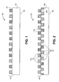
Figure 1 illustrates a cross-sectional view of a polishing pad with a homogeneous body having discrete protrusions thereon, in accordance with an embodiment not covered by the claims. -
Figure 2 illustrates a cross-sectional view of another polishing pad with a homogeneous body having discrete protrusions thereon, in accordance with an embodiment of the present invention. -
Figure 3 illustrates a top-down view of a polishing pad with a homogeneous body having discrete hexagonal tile protrusions thereon, in accordance with an embodiment of the present invention. -
Figure 4 illustrates a top-down view of a polishing pad with a homogeneous body having discrete arc-shaped protrusions thereon, in accordance with an embodiment of the present invention. -
Figure 5 illustrates a top-down view of a polishing pad with a homogeneous body having discrete linear segment protrusions thereon, in accordance with an embodiment of the present invention. -
Figure 6 illustrates a top-down plan view of a polishing pad with a homogeneous body having discrete protrusions thereon and including a local area transparency (LAT) region and/or an indication region, in accordance with an embodiment of the present invention. -
Figures 7A-7G illustrate cross-sectional views of operations used in the fabrication of a polishing pad with a homogeneous body having discrete protrusions thereon, in accordance with an embodiment of the present invention. -
Figures 8A-8D illustrate cross-sectional views of operations used in the fabrication of another polishing pad with a homogeneous body having discrete protrusions thereon, in accordance with an embodiment of the present invention. -
Figure 9 illustrates an isometric side-on view of a polishing apparatus compatible with a polishing pad with a homogeneous body having discrete protrusions thereon, in accordance with an embodiment of the present invention. - Polishing pads with homogeneous bodies having discrete protrusions thereon are described herein. In the following description, numerous specific details are set forth, such as specific polishing pad compositions and designs, in order to provide a thorough understanding of embodiments of the present invention. It will be apparent to one skilled in the art that embodiments of the present invention may be practiced without these specific details. In other instances, well-known processing techniques, such as details concerning the combination of a slurry with a polishing pad to perform CMP of a semiconductor substrate, are not described in detail in order to not unnecessarily obscure embodiments of the present invention. Furthermore, it is to be understood that the various embodiments shown in the figures are illustrative representations and are not necessarily drawn to scale.
- Polishing pads for CMP operations may have trade-offs in performance such as between across-wafer polishing uniformity versus within die polishing uniformity. For example, hard polishing pads may exhibit good die-level planarization, but poor across-wafer uniformity. On the other hand, soft polishing pads may exhibit poor die-level planarization (e.g., they may cause dishing within die), but good wafer-level uniformity. An approach to mitigating the above performance trade-off may be to decouple within-wafer and within-die polishing effects.
- In one attempt, a soft subpad has been paired with a hard polishing layer. However, the structures that make of the hard polishing layer, such as tile structures, tend to unfavorably lean over when compressed into the soft subpad during a polishing operation. Furthermore, delamination of the features of the hard polishing layer from the soft subpad can significantly reduce the life of the polishing pad.
- In accordance with embodiments of the present invention, approaches to mitigating the above described performance trade-off include the formation of polishing pads having hard discrete protrusions covalently bonded with a soft homogeneous body. Other polishing pads have hard discrete protrusions disposed on a soft homogeneous body having hard lateral supporting, yet discontinuous, features to inhibit toppling of the discrete protrusions during compression into the underlying homogeneous body. It is to be understood that reverse arrangements, e.g., soft polishing protrusions disposed on hard underlying homogeneous bodies are also contemplated herein.
- Such multi-layer polishing pads may be fabricated with a molding process to ensure chemical bonding between the protrusions and the underlying homogeneous body. For example, in one embodiment, a multi-layer CMP pads is fabricated in-situ by forming a second pad precursor above a partially cured first pad precursor and further curing both portions together. The first material may be pre-pressed or may not be not-pressed. In either case, the whole pad is pressed and post-cured as an integral polishing pad. By using such an in-situ approach, chemical bonding between layers may be very strong, reducing or eliminating any potential for delamination. In an embodiment, pre-pressing or pressing involves the moving together of upper and lower portions of a molding apparatus.
- In an aspect of the present invention, a polishing pad is provided with a substantially flat homogeneous body having discrete protrusions thereon. For example,
Figure 1 illustrates a cross-sectional view of a polishing pad with a homogeneous body having discrete protrusions thereon, in accordance with an embodiment of the present invention. - Referring to
Figure 1 , apolishing pad 100 is provided for polishing a substrate. Thepolishing pad 100 includes ahomogeneous body 102 having apolishing side 104 and aback side 106. Thehomogeneous body 102 is composed of a material having a first hardness. Thepolishing pad 100 also includes a plurality ofdiscrete protrusions 108 disposed on the polishingside 104 of thehomogeneous body 102. The plurality ofdiscrete protrusions 108 is composed of a material having a second hardness, different from the first hardness. In an embodiment, thepolishing side 104 of thehomogeneous body 102 is substantially flat and is exposed between the plurality ofdiscrete protrusions 108, as depicted inFigure 1 . In one such embodiment, each of the plurality ofdiscrete protrusions 108 has, in a global plane of thepolishing side 104 of thehomogeneous body 102, a shortest dimension approximately in the range of 5 - 50 millimeters. - In accordance with an embodiment of the present invention, the hardness of the material of the homogeneous body 102 (first hardness) is less than the hardness of the material of the plurality of discrete protrusions 108 (second hardness). In one such embodiment, the first hardness is less than approximately 40 Shore D, and the second hardness is greater than approximately 30 Shore D. In a specific such embodiment, the first hardness is less than approximately 25 Shore D, and the second hardness is greater than approximately 40 Shore D.
- In accordance with another embodiment of the present invention, the hardness of the material of the homogeneous body 102 (first hardness) is greater than the hardness of the material of the plurality of discrete protrusions 108 (second hardness). In one such embodiment, the second hardness is less than approximately 40 Shore D, and the first hardness is greater than approximately 30 Shore D. In a specific such embodiment, the second hardness is less than approximately 25 Shore D, and the first hardness is greater than approximately 40 Shore D.
- In another aspect of the present invention, a polishing pad is provided with a topographically patterned homogeneous body having discrete protrusions thereon. For example,
Figure 2 illustrates a cross-sectional view of another polishing pad with a homogeneous body having discrete protrusions thereon, in accordance with an embodiment of the present invention. - Referring to
Figure 2 , apolishing pad 200 is provided for polishing a substrate. Thepolishing pad 200 includes ahomogeneous body 202 having a polishingside 204 and aback side 206. Thehomogeneous body 202 is composed of a material having a first hardness. The polishingside 204 of thehomogeneous body 202 includes a plurality ofprotrusions 207 having a pattern. Thepolishing pad 200 also includes a plurality ofdiscrete protrusions 208 disposed on and aligned with the plurality ofprotrusions 207 of the polishingside 204 of thehomogeneous body 202. The plurality ofdiscrete protrusions 208 has the pattern of the plurality ofprotrusions 207 and is composed of a material having a second hardness, different from the first hardness.Polishing pad 200 also includes afill layer 210 disposed on thehomogeneous body 202, around the plurality ofprotrusions 207 of the polishingside 204 of thehomogeneous body 202. The fill layer is composed the material of the plurality ofdiscrete protrusions 208. In one such embodiment, each of the plurality ofprotrusions 207 and each of the plurality ofdiscrete protrusions 208 has, in a global plane of the polishingside 204 of thehomogeneous body 202, a shortest dimension approximately in the range of 5 - 50 millimeters. - In an embodiment, the
fill layer 210 is discontinuous with the plurality ofdiscrete protrusions 208. That is, referring toFigure 2 , the fill layer is not bonded to or continuous with the plurality ofdiscrete protrusions 208 atlocations 212. Such an arrangement may enable freedom of compression of each of the plurality ofdiscrete protrusions 208 into thehomogeneous body 208 during a polishing process. Yet, the presence ofdiscontinuous fill layer 210 may guide and support either side of each of the plurality ofdiscrete protrusions 208 as they are compressed into thehomogeneous body 208. However, in an alternative embodiment, thefill layer 210 is continuous with the plurality ofdiscrete protrusions 208. - In accordance with an embodiment of the present invention, the hardness of the material of the homogeneous body 202 (first hardness) is less than the hardness of the material of the plurality of
discrete protrusions 208 and the fill layer 210 (second hardness). In one such embodiment, the first hardness is less than approximately 40 Shore D, and the second hardness is greater than approximately 30 Shore D. In a specific such embodiment, the first hardness is less than approximately 25 Shore D, and the second hardness is greater than approximately 40 Shore D. - In accordance with another embodiment of the present invention, the hardness of the material of the homogeneous body 208 (first hardness) is greater than the hardness of the material of the plurality of
discrete protrusions 208 and the fill layer 210 (second hardness). In one such embodiment, the second hardness is less than approximately 40 Shore D, and the first hardness is greater than approximately 30 Shore D. In a specific such embodiment, the second hardness is less than approximately 25 Shore D, and the first hardness is greater than approximately 40 Shore D. - Portions of differing materials within the polishing
pads Figure 1 , in an embodiment, the plurality ofdiscrete protrusions 108 is disposed on and covalently bonded with the polishingside 104 of thehomogeneous body 102. In another example, referring toFigure 2 , in an embodiment, both thefill layer 210 and the plurality ofdiscrete protrusions 208 are covalently bonded with thehomogeneous body 202. Specifically, thefill layer 210 is covalently bonded within the pattern of the polishingside 204, while the plurality ofdiscrete protrusions 208 is covalently bonded on top of the pattern of the polishingside 204. - In an embodiment, the term "covalently bonded" refers to arrangements where atoms from a first material (e.g., the material of
homogeneous body 102 or 202) are cross-linked or share electrons with atoms from a second material (e.g., the material of the plurality ofdiscrete protrusions 108 or 208) to effect actual chemical bonding. Such covalent bonding is distinguished from electrostatic interactions that may result if a portion of a polishing pad is cut out and replaced with an insert region of s differing material. Covalent bonding is also distinguished from mechanical bonding, such as bonding through screws, nails, glues, or other adhesives. As described in detail below, the covalent bonding may be achieved by co-curing, at least to some extent, a polishing body with a plurality of discrete protrusions, as opposed to through separate formation of the polishing body and the plurality of discrete protrusions. - The materials of polishing
pads Figure 1 , in an embodiment, thehomogeneous body 102 is a molded homogeneous body, and the plurality ofdiscrete protrusions 108 is a plurality of molded protrusions. In another example, referring toFigure 2 , in an embodiment, thehomogeneous body 208 is a molded homogeneous body, the plurality ofdiscrete protrusions 208 is a plurality of molded protrusions, and thefill layer 210 is a molded fill layer. - The term "molded" may be used to indicate that a homogeneous body and/or discrete protrusions thereon are formed in a formation mold, as described in more detail below in association with
Figures 7A-7G and8A-8D . In an embodiment, the molded discrete protrusions, upon conditioning and/or polishing, have a polishing surface roughness approximately in the range of 1 - 5 microns root mean square. In one embodiment, the molded discrete protrusions, upon conditioning and/or polishing, have a polishing surface roughness of approximately 2.35 microns root mean square. In an embodiment, the molded discrete protrusions have a storage modulus at 25 degrees Celsius approximately in the range of 30 - 500 megaPascals (MPa). In another embodiment, the molded discrete protrusions have a storage modulus at 25 degrees Celsius approximately less than 30 megaPascals (MPa). In an embodiment, as described in association withFigures 7A-7G and8A-8D , a polishing pad is composed of a molded polishing body and molded discrete protrusions thereon. - The polishing
pads - In an embodiment, the term "thermoset" is used to indicate a polymer material that irreversibly cures, e.g., the precursor to the material changes irreversibly into an infusible, insoluble polymer network by curing. For example, in an embodiment, the term "thermoset" excludes polishing pads composed of, e.g., "thermoplast" materials or "thermoplastics" - those materials composed of a polymer that turns to a liquid when heated and returns to a very glassy state when cooled sufficiently. It is noted that polishing pads made from thermoset materials are typically fabricated from lower molecular weight precursors reacting to form a polymer in a chemical reaction, while pads made from thermoplastic materials are typically fabricated by heating a pre-existing polymer to cause a phase change so that a polishing pad is formed in a physical process. Polyurethane thermoset polymers may be selected for fabricating polishing pads described herein based on their stable thermal and mechanical properties, resistance to the chemical environment, and tendency for wear resistance.
- In one embodiment, referring to
Figure 1 , the material of thehomogeneous body 102 is composed of a first thermoset polyurethane material, and the material of the plurality ofdiscrete protrusions 108 is composed of a second, different, thermoset polyurethane material. In one embodiment, referring toFigure 2 , the material of thehomogeneous body 202 is composed of a first thermoset polyurethane material, and the material of the plurality ofdiscrete protrusions 208 and thefill layer 210 is composed of a second, different, thermoset polyurethane material. - In an embodiment, polishing pads described herein, such as polishing
pads - In an embodiment, the density or concentration of the plurality of closed cells differs between the homogeneous body (e.g., 102 or 202) and the plurality of discrete protrusions (e.g., 108 or 208). In one such embodiment, the density or concentration of closed cells in the homogeneous body is less than that in the plurality of discrete protrusions. In a specific such embodiment, there are no closed cells in the homogeneous body while there are closed cells in the plurality of discrete protrusions. In an alternative embodiment, the density or concentration of closed cells in the homogeneous body is greater than that in the plurality of discrete protrusions. In another embodiment, the type of closed cells differs between the homogeneous body and the plurality of discrete protrusions.
- In an embodiment, polishing pads described herein, such as polishing
pads - In an embodiment, the degree of opaqueness or the concentration of particle filler differs between the homogeneous body (e.g., 102 or 202) and the plurality of discrete protrusions (e.g., 108 or 208). In one such embodiment, the concentration of particle filler in the homogeneous body is less than that in the plurality of discrete protrusions. In a specific such embodiment, there is no particle filler included in the homogeneous body while particle filler is included in the plurality of discrete protrusions. In an alternative embodiment, the concentration of particle filler in the homogeneous body is greater than that in the plurality of discrete protrusions. In another embodiment, the type of particle filler differs between the homogeneous body and the plurality of discrete protrusions.
- In an aspect of the present invention, the plurality of
discrete protrusions Figure 3 illustrates a top-down view of apolishing pad 300 with a homogeneous body having discretehexagonal tile protrusions 302 thereon, in accordance with an embodiment of the present invention. Other specific such embodiments include, but are not limited to, pluralities of circular tiles, oval tiles, square tiles, rectangular tiles, or a combination thereof. - In a second general example, some embodiments of the present invention include a plurality of discrete protrusions having a pattern of curved features. In a specific such example,
Figure 4 illustrates a top-down view of apolishing pad 400 with a homogeneous body having discrete arc-shapedprotrusions 402 thereon, in accordance with an embodiment of the present invention. Other specific such embodiments include, but are not limited to, a plurality of partial circumferential protrusions disposed on a substantially circular homogenous body of the polishing pad. - In a third general example, some embodiments of the present invention include a plurality of discrete protrusions having a pattern of linear features. In a specific such example,
Figure 5 illustrates a top-down view of apolishing pad 500 with a homogeneous body having discretelinear segment protrusions 502 thereon, in accordance with an embodiment of the present invention. The discrete linear segment protrusions shown are essentially orthogonal to radii of the polishing surface. It is to be understood, however, that embodiments of the present invention may also include discrete linear segments that are not precisely orthogonal to radii of the polishing surface. In such embodiments, the discrete linear segments may form a portion of a, but not a complete, concentric or approximately concentric polygon arrangement. The relative association with the corresponding radius in not precisely 90 degrees but rather, perhaps, a fraction of a degree to a few degrees off of 90 degrees. Nonetheless, such near-orthogonal or approximately orthogonal discrete linear segments are considered to be within the spirit and scope of the present invention. - In an embodiment, polishing pads described herein, such as polishing
pads - The sizing of the homogeneous body and the discrete protrusions disposed thereon may be varied according to application. Nonetheless, certain parameters may be used to make polishing pads including such a homogeneous body with discrete protrusions disposed thereon compatible with conventional processing equipment or even with conventional chemical mechanical processing operations. For example, in accordance with an embodiment of the present invention, the combination of the homogeneous body and the discrete protrusions disposed thereon has a thickness approximately in the range of 0.075 inches to 0.130 inches, e.g., approximately in the range of 1.9 - 3.3 millimeters. In one embodiment, the homogeneous body has a diameter approximately in the range of 20 inches to 30.3 inches, e.g., approximately in the range of 50 - 77 centimeters, and possibly approximately in the range of 10 inches to 42 inches, e.g., approximately in the range of 25 - 107 centimeters. In one embodiment, the homogeneous body and/or the discrete protrusions disposed thereon have a pore density approximately in the range of 6% - 36% total void volume, and possibly approximately in the range of 15% - 35% total void volume. In one embodiment, the combination of the homogeneous body and the discrete protrusions disposed thereon has a compressibility of approximately 2.5%. In one embodiment, the homogeneous body has a density approximately in the range of 0.70 - 1.05 grams per cubic centimeter.
- In another aspect of the present invention, a polishing pad with a homogeneous body having discrete protrusions thereon further includes a detection region for use with, e.g., an eddy current detection system. For example,
Figure 6 illustrates a top-down plan view of apolishing pad 600 with a homogeneous body having discrete protrusions thereon and including a local area transparency (LAT) region and/or an indication region, in accordance with an embodiment of the present invention. - Referring to
Figure 6 , the polishingsurface 602 of polishingpad 600 includes anindication region 604 indicating the location of a detection region disposed in the back surface of thepolishing pad 600. In one embodiment, theindication region 604 interrupts a pattern ofprotrusions 606 with a second pattern ofprotrusions 608, as depicted inFigure 6 . Examples of suitable detection regions, such as eddy current detection regions, are described inU.S. patent application 12/895,465 filed on September 30, 2010 - In another aspect, a polishing pad with a homogeneous body having discrete protrusions thereon further includes further includes a local area transparency (LAT) region disposed in the polishing pad. For example, referring again to
Figure 6 , aLAT region 610 is disposed in the polishing body of polishingpad 600. As depicted inFigure 6 , theLAT region 604 interrupts the pattern ofprotrusions 606. In an embodiment, theLAT region 610 is disposed in, and covalently bonded with, a homogeneous body of thepolishing pad 600. Examples of suitable LAT regions are described inU.S. patent application 12/895,465 filed on September 30, 2010 - In another aspect of the present invention, polishing pads having a homogeneous body with a plurality of discrete protrusions disposed thereon may be fabricated in a molding process. In a first such example,
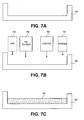
Figures 7A-7G illustrate cross-sectional views of operations used in the fabrication of a polishing pad with a homogeneous body having discrete protrusions thereon, in accordance with an embodiment of the present invention. - Referring to
Figure 7A , aformation mold 700 is provided. Referring toFigure 7B , a pre-polymer 702 and a curative 704 are mixed to form afirst mixture 706 in theformation mold 700, as depicted inFigure 7C . In an embodiment, mixing the pre-polymer 702 and the curative 704 includes mixing an isocyanate and an aromatic diamine compound, respectively. In one embodiment, the mixing further includes adding an opacifying particle filler to the pre-polymer 702 and the curative 704 to ultimately provide an opaque molded homogeneous body of a polishing pad. In a specific embodiment, the opacifying particle filler is a material such as, but not limited to: boron nitride, cerium fluoride, graphite, graphite fluoride, molybdenum sulfide, niobium sulfide, talc, tantalum sulfide, tungsten disulfide, or Teflon. - In an embodiment, the
first mixture 706 is used to ultimately form a molded homogeneous body composed of a thermoset, closed cell polyurethane material. In one embodiment, thefirst mixture 706 is used to ultimately form a hard homogeneous body and only a single type of curative is used. In another embodiment, thefirst mixture 706 is used to ultimately form a soft homogeneous body and a combination of a primary and a secondary curative is used. For example, in a specific embodiment, the pre-polymer includes a polyurethane precursor, the primary curative includes an aromatic diamine compound, and the secondary curative includes a compound having an ether linkage. In a particular embodiment, the polyurethane precursor is an isocyanate, the primary curative is an aromatic diamine, and the secondary curative is a curative such as, but not limited to, polytetramethylene glycol, amino-functionalized glycol, or amino-functionalized polyoxypropylene. In an embodiment, the pre-polymer, a primary curative, and a secondary curative have an approximate molar ratio of 100 parts pre-polymer, 85 parts primary curative, and 15 parts secondary curative. It is to be understood that variations of the ratio may be used to provide a homogeneous body with varying hardness values, or based on the specific nature of the pre-polymer and the first and second curatives. - Referring to
Figure 7D , themixture 706 is at least partially cured to form a moldedhomogeneous body 708 having a polishingside 710 and aback side 712. The partial curing may be performed by heating themold 700 in the presence or absence of a formation mold lid. A second pre-polymer and a second curative are then mixed to form asecond mixture 714 on the moldedhomogeneous body 708, as depicted inFigure 7E . In an embodiment, thesecond mixture 714 is for forming a hard material, and a pre-polymer along with a single curative is used (2-tank process), while thefirst mixture 706 is for forming a soft material, and a pre-polymer along with a primary curative and a secondary curative is used (3-tank process). In an alternative embodiment, thefirst mixture 706 is for forming a hard material, and a pre-polymer along with a single curative is used (2-tank process), while thesecond mixture 714 is for forming a soft material, and a pre-polymer along with a primary curative and a secondary curative is used (3-tank process). Thus, in an embodiment, thesecond mixture 714 is different from thefirst mixture 706. However, in an alternative embodiment, the two mixtures are the same. Also, in an embodiment, the second mixture is dispensed on a partially or completely curedfirst mixture 706. However, in an alternative embodiment, the pouring or dispensing of thesecond mixture 714 may be poured in situ into thefirst mixture 706 to be applied for the same layer, but in a different region. In a specific such embodiment, the center ring and outer ring have different formulations. In an embodiment where two distinct layers are formed, in order to strengthen the chemical bonding between layers, the ratio of functional group within different layers is different, e.g., one layer is -NCO rich and the other layer is -NH2 and/or -OH rich. In an embodiment, a coating is applied between different layers. In an embodiment, penetration occurs between layers and strengthens the chemical bonding, such as the covalent bonding. - In an embodiment, the mixing of the second pre-polymer and the second curative further includes adding an opacifying particle filler to the second pre-polymer and the second curative to form an opaque plurality of
discrete protrusions 718. In an embodiment, mixing the first pre-polymer and the first curative to form thefirst mixture 706 includes degassing thefirst mixture 706, and mixing the second pre-polymer and the second curative to form thesecond mixture 714 includes degassing thesecond mixture 714. - Referring to
Figure 7F , alid 716 of theformation mold 700 is placed into thesecond mixture 714. A top-down plan view oflid 716 is shown on top, while a cross-section along the a-a' axis is shown below inFigure 7F . Thelid 716 has disposed thereon a pattern of grooves, such as a pattern of grooves corresponding to the pattern of protrusions described in association withFigure 3 , as depicted infigure 7F . Alternatively, however,lid 716 has disposed thereon a pattern of grooves corresponding to the patterns of protrusions described in association withFigures 4 and5 . - It is to be understood that embodiments described herein that describe lowering the
lid 716 of aformation mold 700 need only achieve a bringing together of thelid 716 and a base of theformation mold 700. That is, in some embodiments, a base of aformation mold 700 is raised toward alid 716 of a formation mold, while in other embodiments alid 716 of aformation mold 700 is lowered toward a base of theformation mold 700 at the same time as the base is raised toward thelid 716. - With the
lid 716 placed in thesecond mixture 714, thesecond mixture 714 is at least partially cured to form a plurality ofdiscrete protrusions 718 disposed on the polishingside 710 of the moldedhomogeneous body 708. The pattern of grooves of thelid 716 is used to stamp a pattern of protrusions from thesecond mixture 714 in theformation mold 700. Thesecond mixture 714 may be heated under pressure (e.g., with thelid 716 in place) to provide the moldeddiscrete protrusions 718. In an embodiment, heating in theformation mold 700 includes at least partially curing in the presence oflid 716, which encloses thesecond mixture 714 information mold 700, at a temperature approximately in the range of 200 - 260 degrees Fahrenheit and a pressure approximately in the range of 2 - 12 pounds per square inch. - In an embodiment, the
second mixture 714 is different from thefirst mixture 706, and, upon fully curing the first 706 and second 714 mixtures, the hardness of the plurality ofdiscrete protrusions 718 is different from the hardness of the moldedhomogeneous body 708. In an embodiment, at least partially curing thesecond mixture 714 includes covalently boding the plurality ofdiscrete protrusions 718 with the moldedhomogeneous body 708. In an embodiment, forming the moldedhomogeneous body 708 includes forming a first thermoset polyurethane material, and forming the plurality ofdiscrete protrusions 718 includes forming a second, different, thermoset polyurethane material. - Referring to
Figure 7G , apolishing pad 720 is provided upon removal of the moldedhomogeneous body 708 with the plurality ofdiscrete protrusions 718 disposed thereon from theformation mold 700. The plurality ofdiscrete protrusions 718 has a pattern corresponding to the pattern of grooves of thelid 716. A top-down plan view of thepolishing pad 720 is shown below, while a cross-section taken along the b-b' axis is shown above inFigure 7G . In an embodiment, the polishingside 710 of the moldedhomogeneous body 708 is substantially flat and is exposed between the plurality ofdiscrete protrusions 718, as depicted in the cross-sectional view ofFigure 7G . - It is noted that further curing through heating may be desirable and may be performed by placing the
polishing pad 720 in an oven and heating. Thus, in one embodiment, curing the first andsecond mixtures formation mold 700 and then further curing in an oven. Either way, apolishing pad 720 is ultimately provided, wherein a moldedhomogeneous body 708 of thepolishing pad 720 has a polishingside 710 with a plurality of moldedprotrusions 718 disposed thereon. In an embodiment, both the moldedhomogeneous body 708 and the plurality of moldedprotrusions 718 are composed of thermoset polyurethane materials and a plurality of closed cell pores disposed in the thermoset polyurethane materials. - A similar method to the one described in association with
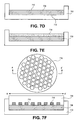
Figure 7A-7G may be used to fabricate a polishing pad with a topographically patterned homogeneous body having discrete protrusions thereon. For example,Figures 8A-8D illustrate cross-sectional views of operations used in the fabrication of another polishing pad with a homogeneous body having discrete protrusions thereon, in accordance with an embodiment of the present invention. - Referring again to
Figure 7C , and now toFigure 8A , instead of at least partially curing thefirst mixture 706 to provide a substantially flat surface for ahomogeneous body 708, the lid 716 (described in association withFigure 7F ) is used to first form moldedhomogeneous body 800 with a polishingside 802 having a plurality ofprotrusions 804 with a pattern corresponding to the pattern of grooves of thelid 716. For example, subsequent to mixing the first pre-polymer and the first curative to form thefirst mixture 706 but prior to mixing the second pre-polymer and the second curative to form thesecond mixture 714, thelid 716 of theformation mold 700 is placed into thefirst mixture 706. With the lid placed in thefirst mixture 706, thefirst mixture 706 is at least partially cured, as depicted inFigure 8B . - Referring to
Figure 8C , the second pre-polymer and the second curative are then mixed to form thesecond mixture 714 on the moldedhomogeneous body 800. Thelid 716 of theformation mold 700 is then placed into thesecond mixture 714, as depicted inFigure 8D . With thelid 716 placed in thesecond mixture 714, thesecond mixture 714 is at least partially cured to form a plurality ofdiscrete protrusions 718 disposed on and aligned with the plurality ofprotrusions 804 of the polishingside 802 of the moldedhomogeneous body 800. The pattern of grooves of thelid 716 is used to stamp a pattern of protrusions from thesecond mixture 714 in theformation mold 700. Thesecond mixture 714 may then be heated under pressure (e.g., with thelid 716 in place) to provide the moldeddiscrete protrusions 718. In an embodiment, heating in theformation mold 700 includes at least partially curing in the presence oflid 716, which encloses thesecond mixture 714 information mold 700, at a temperature approximately in the range of 200 - 260 degrees Fahrenheit and a pressure approximately in the range of 2 - 12 pounds per square inch. A polishing pad such as thepolishing pad 200 described in association withFigure 2 may thus be formed. - Referring again to
Figure 8D , in an embodiment, forming thesecond mixture 714 on the moldedhomogeneous body 800 includes forming an amount of thesecond mixture 714 sufficiently large to form afill layer 806 disposed on the moldedhomogeneous body 800, around the plurality ofprotrusions 804 of the polishingside 802 of the moldedhomogeneous body 800. In one such embodiment, the amount of thesecond mixture 714 is sufficiently small to form thefill layer 806 discontinuous with the plurality ofdiscrete protrusions 718 formed from thesecond mixture 714. An example of such discontinuity is described above in association with polishingpad 200 ofFigure 2 . In an embodiment, a spin plate is used to control the amount and thickness of thesecond mixture 714 dispensed on the polishingside 802 of the moldedhomogeneous body 800. - In an embodiment, the plurality of
discrete protrusions 718 is formed on and aligned with the plurality ofprotrusions 804 of the polishingside 802 of the moldedhomogeneous body 800. The alignment may tolerate some slight misalignment. For example, a slippage approximately in the range of up to 1/1000th on an inch may be acceptable between separate introduction of thelid 716 into thefirst mixture 706 and thesecond mixture 714, respectively. - In an embodiment, referring again to
Figure 7B , the mixing further includes adding a plurality ofporogens 722 to the pre-polymer 702 and the curative 704 to provide closed cell pores in the ultimately formed body of the polishing pad. Thus, in one embodiment, each closed cell pore has a physical shell. In another embodiment, referring again toFigure 7B , the mixing further includes injecting agas 724 into to the pre-polymer 702 and the curative 704, or into a product formed there from, to provide closed cell pores in the ultimately formed body of the polishing pad. Thus, in one embodiment, each closed cell pore has no physical shell. In a combination embodiment, the mixing further includes adding a plurality ofporogens 722 to the pre-polymer 702 and the curative 704 to provide a first portion of closed cell pores each having a physical shell, and further injecting agas 724 into the pre-polymer 702 and the curative 704, or into a product formed there from, to provide a second portion of closed cell pores each having no physical shell. In yet another embodiment, the pre-polymer 702 is an isocyanate and the mixing further includes adding water (H2O) to the pre-polymer 702 and the curative 704 to provide closed cell pores each having no physical shell. In an embodiment, referring toFigure 7E and8C , a plurality of porogens may similarly be included in a molded discrete plurality ofprotrusions 718. - Thus, protrusion patterns contemplated in embodiments of the present invention may be formed in-situ. For example, as described above, a compression-molding process may be used to form polishing pads with a molded homogeneous body having molded discrete protrusions disposed thereon. By using a molding process, highly uniform protrusion dimensions within-pad may be achieved. Furthermore, extremely reproducible protrusion dimensions along with very smooth, clean protrusion surfaces may be produced. Other advantages may include reduced defects and micro-scratches and a greater usable protrusion depth.
- Polishing pads described herein may be suitable for use with a variety of chemical mechanical polishing apparatuses. As an example,
Figure 9 illustrates an isometric side-on view of a polishing apparatus compatible with a polishing pad with a homogeneous body having discrete protrusions thereon, in accordance with an embodiment of the present invention. - Referring to
Figure 9 , apolishing apparatus 900 includes aplaten 904. Thetop surface 902 ofplaten 904 may be used to support a polishing pad with a homogeneous body having discrete protrusions thereon.Platen 904 may be configured to providespindle rotation 906 andslider oscillation 908. Asample carrier 910 is used to hold, e.g., asemiconductor wafer 911 in place during polishing of the semiconductor wafer with a polishing pad.Sample carrier 910 is further supported by asuspension mechanism 912. Aslurry feed 914 is included for providing slurry to a surface of a polishing pad prior to and during polishing of the semiconductor wafer. Aconditioning unit 990 may also be included and, in one embodiment, includes a diamond tip for conditioning a polishing pad.
Claims (17)
- A polishing pad for polishing a substrate, the polishing pad comprising:a homogeneous body having a polishing side and a back side, the homogeneous body comprising a material having a first hardness, and the polishing side comprising a plurality of protrusions having a pattern;a plurality of discrete protrusions disposed on and aligned with the plurality of protrusions of the polishing side of the homogeneous body, the plurality of discrete protrusions comprising a material having a second hardness different from the first hardness, and the plurality of discrete protrusions having the pattern; anda fill layer disposed on the homogeneous body, around the plurality of protrusions of the polishing side of the homogeneous body, the fill layer comprising the material of the plurality of discrete protrusions.
- The polishing pad of claim 1, wherein the fill layer is discontinuous with the plurality of discrete protrusions.
- The polishing pad of claim 1, wherein both the fill layer and the plurality of discrete protrusions are covalently bonded with the homogeneous body.
- The polishing pad of claim 1, wherein the homogeneous body is a molded homogeneous body, wherein the plurality of discrete protrusions is a plurality of molded protrusions, and wherein the fill layer is a molded fill layer.
- The polishing pad of claim 1, wherein the material of the homogeneous body comprises a first thermoset polyurethane material, and the material of the plurality of discrete protrusions and the fill layer comprises a second, different, thermoset polyurethane material.
- The polishing pad of claim 1, wherein the first hardness of the material of the homogeneous body is less than the second hardness of the material of the plurality of discrete protrusions and the fill layer.
- The polishing pad of claim 6, wherein the first hardness is less than approximately 40 Shore D, and the second hardness is greater than approximately 30 Shore D.
- The polishing pad of claim 7, wherein the first hardness is less than approximately 25 Shore D, and the second hardness is greater than approximately 40 Shore D.
- The polishing pad of claim 1, wherein the first hardness of the material of the homogeneous body is greater than the second hardness of the material of the plurality of discrete protrusions and the fill layer.
- The polishing pad of claim 9, wherein the second hardness is less than approximately 40 Shore D, and the first hardness is greater than approximately 30 Shore D.
- The polishing pad of claim 10, wherein the second hardness is less than approximately 25 Shore D, and the first hardness is greater than approximately 40 Shore D.
- The polishing pad of claim 1, wherein the homogeneous body is substantially circular, and one or more of the plurality of discrete protrusions is a partial circumferential protrusion or an arc-shaped protrusion.
- The polishing pad of claim 1, wherein the plurality of discrete protrusions comprises a plurality of tiles selected from the group consisting of circular tiles, oval tiles, square tiles, hexagonal tiles, and rectangular tiles.
- The polishing pad of claim 1, wherein each of the plurality of discrete protrusions has, in a global plane of the polishing side of the homogeneous body, a shortest dimension approximately in the range of 5 - 50 millimeters.
- The polishing pad of claim 1, further comprising:a detection region disposed in the back side of the homogeneous body.
- The polishing pad of claim 1, further comprising:a local area transparency (LAT) region disposed in the homogeneous body.
- A method of fabricating a polishing pad for polishing a substrate, the method comprising:mixing a first set of polymerizable materials to form a first mixture in the base of a formation mold;at least partially curing the first mixture to form a molded homogeneous body having a polishing side and a back side;mixing a second set of polymerizable materials to form a second mixture on the molded homogeneous body;placing a lid of the formation mold into the second mixture, the lid having disposed thereon a pattern of grooves; and, with the lid placed in the second mixture, at least partially curing the second mixture to form a plurality of discrete protrusions disposed on the polishing side of the molded homogeneous body, the plurality of discrete protrusions having a pattern corresponding to the pattern of grooves of the lid; andthe method further comprising:subsequent to mixing the first set of polymerizable materials to form the first mixture but prior to mixing the second set of polymerizable materials to form the second mixture, placing the lid of the formation mold into the first mixture and, with the lid placed in the first mixture, performing the at least partially curing the first mixture to form the molded homogeneous body with the polishing side comprising a plurality of protrusions having a pattern corresponding to the pattern of grooves of the lid, wherein the plurality of discrete protrusions is formed on and aligned with the plurality of protrusions of the polishing side of the molded homogeneous body.
Priority Applications (1)
| Application Number | Priority Date | Filing Date | Title |
|---|---|---|---|
| EP14198969.9A EP2857145B1 (en) | 2011-05-23 | 2012-05-16 | Polishing pad with homogeneous body having discrete protrusions thereon |
Applications Claiming Priority (2)
| Application Number | Priority Date | Filing Date | Title |
|---|---|---|---|
| US13/113,655 US20120302148A1 (en) | 2011-05-23 | 2011-05-23 | Polishing pad with homogeneous body having discrete protrusions thereon |
| PCT/US2012/038212 WO2012162066A1 (en) | 2011-05-23 | 2012-05-16 | Polishing pad with homogeneous body having discrete protrusions thereon |
Related Child Applications (2)
| Application Number | Title | Priority Date | Filing Date |
|---|---|---|---|
| EP14198969.9A Division-Into EP2857145B1 (en) | 2011-05-23 | 2012-05-16 | Polishing pad with homogeneous body having discrete protrusions thereon |
| EP14198969.9A Division EP2857145B1 (en) | 2011-05-23 | 2012-05-16 | Polishing pad with homogeneous body having discrete protrusions thereon |
Publications (2)
| Publication Number | Publication Date |
|---|---|
| EP2714331A1 EP2714331A1 (en) | 2014-04-09 |
| EP2714331B1 true EP2714331B1 (en) | 2015-04-01 |
Family
ID=46147792
Family Applications (2)
| Application Number | Title | Priority Date | Filing Date |
|---|---|---|---|
| EP14198969.9A Active EP2857145B1 (en) | 2011-05-23 | 2012-05-16 | Polishing pad with homogeneous body having discrete protrusions thereon |
| EP12723065.4A Active EP2714331B1 (en) | 2011-05-23 | 2012-05-16 | Polishing pad with homogeneous body having discrete protrusions thereon |
Family Applications Before (1)
| Application Number | Title | Priority Date | Filing Date |
|---|---|---|---|
| EP14198969.9A Active EP2857145B1 (en) | 2011-05-23 | 2012-05-16 | Polishing pad with homogeneous body having discrete protrusions thereon |
Country Status (7)
| Country | Link |
|---|---|
| US (2) | US20120302148A1 (en) |
| EP (2) | EP2857145B1 (en) |
| JP (3) | JP5657178B2 (en) |
| KR (2) | KR101831909B1 (en) |
| CN (1) | CN103561907B (en) |
| TW (2) | TWI504479B (en) |
| WO (1) | WO2012162066A1 (en) |
Families Citing this family (53)
| Publication number | Priority date | Publication date | Assignee | Title |
|---|---|---|---|---|
| US20120302148A1 (en) | 2011-05-23 | 2012-11-29 | Rajeev Bajaj | Polishing pad with homogeneous body having discrete protrusions thereon |
| US9079289B2 (en) * | 2011-09-22 | 2015-07-14 | Toyo Tire & Rubber Co., Ltd. | Polishing pad |
| US9067297B2 (en) | 2011-11-29 | 2015-06-30 | Nexplanar Corporation | Polishing pad with foundation layer and polishing surface layer |
| KR101685678B1 (en) * | 2011-11-29 | 2016-12-12 | 넥스플래너 코퍼레이션 | Polishing pad with foundation layer and polishing surface layer |
| US9067298B2 (en) * | 2011-11-29 | 2015-06-30 | Nexplanar Corporation | Polishing pad with grooved foundation layer and polishing surface layer |
| WO2013151946A1 (en) * | 2012-04-02 | 2013-10-10 | Thomas West Inc. | Methods and systems for centrifugal casting of polymer polish pads and polishing pads made by the methods |
| US10722997B2 (en) | 2012-04-02 | 2020-07-28 | Thomas West, Inc. | Multilayer polishing pads made by the methods for centrifugal casting of polymer polish pads |
| US10022842B2 (en) | 2012-04-02 | 2018-07-17 | Thomas West, Inc. | Method and systems to control optical transmissivity of a polish pad material |
| US9597769B2 (en) | 2012-06-04 | 2017-03-21 | Nexplanar Corporation | Polishing pad with polishing surface layer having an aperture or opening above a transparent foundation layer |
| US9649742B2 (en) | 2013-01-22 | 2017-05-16 | Nexplanar Corporation | Polishing pad having polishing surface with continuous protrusions |
| US10160092B2 (en) * | 2013-03-14 | 2018-12-25 | Cabot Microelectronics Corporation | Polishing pad having polishing surface with continuous protrusions having tapered sidewalls |
| US20150038066A1 (en) * | 2013-07-31 | 2015-02-05 | Nexplanar Corporation | Low density polishing pad |
| SG11201608134YA (en) * | 2014-04-03 | 2016-10-28 | 3M Innovative Properties Co | Polishing pads and systems and methods of making and using the same |
| JP6295807B2 (en) * | 2014-04-28 | 2018-03-20 | 株式会社リコー | Polishing tool and polishing apparatus |
| US9238294B2 (en) * | 2014-06-18 | 2016-01-19 | Nexplanar Corporation | Polishing pad having porogens with liquid filler |
| US9649741B2 (en) * | 2014-07-07 | 2017-05-16 | Jh Rhodes Company, Inc. | Polishing material for polishing hard surfaces, media including the material, and methods of forming and using same |
| US9873180B2 (en) * | 2014-10-17 | 2018-01-23 | Applied Materials, Inc. | CMP pad construction with composite material properties using additive manufacturing processes |
| US10875145B2 (en) * | 2014-10-17 | 2020-12-29 | Applied Materials, Inc. | Polishing pads produced by an additive manufacturing process |
| US9776361B2 (en) | 2014-10-17 | 2017-10-03 | Applied Materials, Inc. | Polishing articles and integrated system and methods for manufacturing chemical mechanical polishing articles |
| WO2016061585A1 (en) * | 2014-10-17 | 2016-04-21 | Applied Materials, Inc. | Polishing pads produced by an additive manufacturing process |
| US10875153B2 (en) | 2014-10-17 | 2020-12-29 | Applied Materials, Inc. | Advanced polishing pad materials and formulations |
| US10821573B2 (en) | 2014-10-17 | 2020-11-03 | Applied Materials, Inc. | Polishing pads produced by an additive manufacturing process |
| US10399201B2 (en) * | 2014-10-17 | 2019-09-03 | Applied Materials, Inc. | Advanced polishing pads having compositional gradients by use of an additive manufacturing process |
| US11745302B2 (en) | 2014-10-17 | 2023-09-05 | Applied Materials, Inc. | Methods and precursor formulations for forming advanced polishing pads by use of an additive manufacturing process |
| CN107078048B (en) * | 2014-10-17 | 2021-08-13 | 应用材料公司 | CMP pad construction with composite material properties using additive manufacturing process |
| JP6476924B2 (en) | 2015-01-30 | 2019-03-06 | 株式会社リコー | Polishing sheet, polishing tool, and polishing method |
| US10092998B2 (en) * | 2015-06-26 | 2018-10-09 | Rohm And Haas Electronic Materials Cmp Holdings, Inc. | Method of making composite polishing layer for chemical mechanical polishing pad |
| KR20180026779A (en) * | 2015-07-30 | 2018-03-13 | 제이에이치 로드스 컴퍼니, 인크 | Systems comprising polymeric lapping materials, media, polymeric lapping materials, and methods of using and forming them |
| CN112059937B (en) * | 2015-10-16 | 2022-11-01 | 应用材料公司 | Method and apparatus for forming advanced polishing pads using additive manufacturing processes |
| CN113103145B (en) * | 2015-10-30 | 2023-04-11 | 应用材料公司 | Apparatus and method for forming polishing article having desired zeta potential |
| CN105500183B (en) * | 2015-11-26 | 2018-08-10 | 上海集成电路研发中心有限公司 | A kind of grinding pad and its service life detection method |
| CN105598866B (en) * | 2015-12-28 | 2017-07-21 | 郑州磨料磨具磨削研究所有限公司 | A kind of manufacture method for electroplating extra hard material grinding wheel |
| US10391605B2 (en) | 2016-01-19 | 2019-08-27 | Applied Materials, Inc. | Method and apparatus for forming porous advanced polishing pads using an additive manufacturing process |
| CN117283450A (en) | 2016-01-19 | 2023-12-26 | 应用材料公司 | Porous chemical mechanical polishing pad |
| JP7193221B2 (en) | 2016-01-25 | 2022-12-20 | 富士紡ホールディングス株式会社 | Polishing pad, method for producing same, and method for producing abrasive product |
| TWI629297B (en) * | 2016-07-05 | 2018-07-11 | 智勝科技股份有限公司 | Polishing layer and method of forming the same and polishing method |
| US10195713B2 (en) | 2016-08-11 | 2019-02-05 | 3M Innovative Properties Company | Lapping pads and systems and methods of making and using the same |
| US10596763B2 (en) | 2017-04-21 | 2020-03-24 | Applied Materials, Inc. | Additive manufacturing with array of energy sources |
| US11471999B2 (en) | 2017-07-26 | 2022-10-18 | Applied Materials, Inc. | Integrated abrasive polishing pads and manufacturing methods |
| US11072050B2 (en) | 2017-08-04 | 2021-07-27 | Applied Materials, Inc. | Polishing pad with window and manufacturing methods thereof |
| WO2019032286A1 (en) | 2017-08-07 | 2019-02-14 | Applied Materials, Inc. | Abrasive delivery polishing pads and manufacturing methods thereof |
| AU2019200390B2 (en) | 2018-01-31 | 2024-04-11 | Dow Global Technologies Llc | Coating formulation with a poly(oxyalkylene-urethane) associative thickener modified with a hydrophobic oligomer |
| CN110815037B (en) * | 2018-08-08 | 2021-07-30 | 湖北鼎龙控股股份有限公司 | Polishing pad and preparation method and application thereof |
| CN112654655A (en) | 2018-09-04 | 2021-04-13 | 应用材料公司 | Advanced polishing pad formulations |
| CN108972319A (en) * | 2018-09-18 | 2018-12-11 | 长鑫存储技术有限公司 | Chemical and mechanical grinding cushion and preparation method thereof |
| US20200230781A1 (en) * | 2019-01-23 | 2020-07-23 | Applied Materials, Inc. | Polishing pads formed using an additive manufacturing process and methods related thereto |
| US11845157B2 (en) * | 2019-05-07 | 2023-12-19 | Cmc Materials, Inc. | Chemical mechanical planarization pads via vat-based production |
| CN110614580B (en) * | 2019-10-22 | 2021-11-19 | 西安奕斯伟材料科技有限公司 | Polishing pad, preparation method thereof and chemical mechanical polishing equipment |
| US11813712B2 (en) | 2019-12-20 | 2023-11-14 | Applied Materials, Inc. | Polishing pads having selectively arranged porosity |
| CN113070810A (en) * | 2020-01-03 | 2021-07-06 | 铨科光电材料股份有限公司 | Wafer polishing pad |
| US11806829B2 (en) | 2020-06-19 | 2023-11-07 | Applied Materials, Inc. | Advanced polishing pads and related polishing pad manufacturing methods |
| US11878389B2 (en) | 2021-02-10 | 2024-01-23 | Applied Materials, Inc. | Structures formed using an additive manufacturing process for regenerating surface texture in situ |
| WO2024064259A1 (en) * | 2022-09-22 | 2024-03-28 | Cmc Materials Llc | Chemical mechanical polishing pads with a disulfide bridge |
Family Cites Families (69)
| Publication number | Priority date | Publication date | Assignee | Title |
|---|---|---|---|---|
| US1953983A (en) * | 1928-02-07 | 1934-04-10 | Carborundum Co | Manufacture of rubber bonded abrasive articles |
| JPS6179575A (en) * | 1984-09-25 | 1986-04-23 | Achilles Corp | Abrasive ground fabric and manufacturing method thereof |
| IE61697B1 (en) | 1987-12-22 | 1994-11-16 | De Beers Ind Diamond | Abrasive product |
| US5190568B1 (en) | 1989-01-30 | 1996-03-12 | Ultimate Abrasive Syst Inc | Abrasive tool with contoured surface |
| US5014468A (en) * | 1989-05-05 | 1991-05-14 | Norton Company | Patterned coated abrasive for fine surface finishing |
| US5177908A (en) * | 1990-01-22 | 1993-01-12 | Micron Technology, Inc. | Polishing pad |
| US5020283A (en) * | 1990-01-22 | 1991-06-04 | Micron Technology, Inc. | Polishing pad with uniform abrasion |
| US5212910A (en) * | 1991-07-09 | 1993-05-25 | Intel Corporation | Composite polishing pad for semiconductor process |
| KR0165625B1 (en) * | 1993-06-02 | 1999-02-01 | 기타지마 요시토시 | Grinding tape and method of manufacturing the grinding tape |
| US5453106A (en) * | 1993-10-27 | 1995-09-26 | Roberts; Ellis E. | Oriented particles in hard surfaces |
| US5391210A (en) * | 1993-12-16 | 1995-02-21 | Minnesota Mining And Manufacturing Company | Abrasive article |
| US5893796A (en) * | 1995-03-28 | 1999-04-13 | Applied Materials, Inc. | Forming a transparent window in a polishing pad for a chemical mechanical polishing apparatus |
| US5958794A (en) * | 1995-09-22 | 1999-09-28 | Minnesota Mining And Manufacturing Company | Method of modifying an exposed surface of a semiconductor wafer |
| US5609517A (en) * | 1995-11-20 | 1997-03-11 | International Business Machines Corporation | Composite polishing pad |
| US5624303A (en) * | 1996-01-22 | 1997-04-29 | Micron Technology, Inc. | Polishing pad and a method for making a polishing pad with covalently bonded particles |
| JPH106218A (en) * | 1996-06-27 | 1998-01-13 | Minnesota Mining & Mfg Co <3M> | Abrasive product for dressing |
| US6194317B1 (en) * | 1998-04-30 | 2001-02-27 | 3M Innovative Properties Company | Method of planarizing the upper surface of a semiconductor wafer |
| KR100485846B1 (en) | 1997-05-09 | 2005-04-28 | 롬 앤드 하스 일렉트로닉 머티리얼스 씨엠피 홀딩스, 인코포레이티드 | Mosaic polishing pads and methods relating thereto |
| US5921855A (en) | 1997-05-15 | 1999-07-13 | Applied Materials, Inc. | Polishing pad having a grooved pattern for use in a chemical mechanical polishing system |
| JP2000033553A (en) * | 1998-05-11 | 2000-02-02 | Sony Corp | Polishing pad and polishing method |
| JP2918883B1 (en) * | 1998-07-15 | 1999-07-12 | 日本ピラー工業株式会社 | Polishing pad |
| US6183346B1 (en) | 1998-08-05 | 2001-02-06 | 3M Innovative Properties Company | Abrasive article with embossed isolation layer and methods of making and using |
| US6299508B1 (en) * | 1998-08-05 | 2001-10-09 | 3M Innovative Properties Company | Abrasive article with integrally molded front surface protrusions containing a grinding aid and methods of making and using |
| US6413153B1 (en) * | 1999-04-26 | 2002-07-02 | Beaver Creek Concepts Inc | Finishing element including discrete finishing members |
| US6179887B1 (en) * | 1999-02-17 | 2001-01-30 | 3M Innovative Properties Company | Method for making an abrasive article and abrasive articles thereof |
| US6217426B1 (en) * | 1999-04-06 | 2001-04-17 | Applied Materials, Inc. | CMP polishing pad |
| US6498101B1 (en) * | 2000-02-28 | 2002-12-24 | Micron Technology, Inc. | Planarizing pads, planarizing machines and methods for making and using planarizing pads in mechanical and chemical-mechanical planarization of microelectronic device substrate assemblies |
| US6736709B1 (en) | 2000-05-27 | 2004-05-18 | Rodel Holdings, Inc. | Grooved polishing pads for chemical mechanical planarization |
| US6454634B1 (en) | 2000-05-27 | 2002-09-24 | Rodel Holdings Inc. | Polishing pads for chemical mechanical planarization |
| US20030207659A1 (en) * | 2000-11-03 | 2003-11-06 | 3M Innovative Properties Company | Abrasive product and method of making and using the same |
| JP2002172563A (en) | 2000-11-24 | 2002-06-18 | Three M Innovative Properties Co | Abrasive tape |
| KR100905266B1 (en) * | 2000-12-01 | 2009-06-29 | 도요 고무 고교 가부시키가이샤 | Polishing pad |
| US6523215B2 (en) * | 2001-04-04 | 2003-02-25 | Saint-Gobain Abrasives Technology Company | Polishing pad and system |
| US6544373B2 (en) * | 2001-07-26 | 2003-04-08 | United Microelectronics Corp. | Polishing pad for a chemical mechanical polishing process |
| JP2003053657A (en) * | 2001-08-10 | 2003-02-26 | Ebara Corp | Polishing surface structural member and polishing device using the same |
| JP3851135B2 (en) * | 2001-10-17 | 2006-11-29 | ニッタ・ハース株式会社 | Polishing pad |
| US7399516B2 (en) * | 2002-05-23 | 2008-07-15 | Novellus Systems, Inc. | Long-life workpiece surface influencing device structure and manufacturing method |
| US8602851B2 (en) | 2003-06-09 | 2013-12-10 | Rohm And Haas Electronic Materials Cmp Holdings, Inc. | Controlled penetration subpad |
| US7201647B2 (en) | 2002-06-07 | 2007-04-10 | Praxair Technology, Inc. | Subpad having robust, sealed edges |
| US6838169B2 (en) | 2002-09-11 | 2005-01-04 | Psiloquest, Inc. | Polishing pad resistant to delamination |
| KR100465649B1 (en) | 2002-09-17 | 2005-01-13 | 한국포리올 주식회사 | Integral polishing pad and manufacturing method thereof |
| JP2004243428A (en) * | 2003-02-12 | 2004-09-02 | Rodel Nitta Co | Polishing pad |
| KR100661444B1 (en) * | 2003-04-25 | 2006-12-27 | 제이에스알 가부시끼가이샤 | Polishing Pad and Chemical Mechanical Polishing Method |
| US6884156B2 (en) | 2003-06-17 | 2005-04-26 | Cabot Microelectronics Corporation | Multi-layer polishing pad material for CMP |
| JP2005074614A (en) * | 2003-09-03 | 2005-03-24 | Nitta Haas Inc | Polishing pad and its manufacturing method |
| US7654885B2 (en) * | 2003-10-03 | 2010-02-02 | Applied Materials, Inc. | Multi-layer polishing pad |
| US7204742B2 (en) * | 2004-03-25 | 2007-04-17 | Cabot Microelectronics Corporation | Polishing pad comprising hydrophobic region and endpoint detection port |
| JP2005277130A (en) * | 2004-03-25 | 2005-10-06 | Fujitsu Ltd | Method of manufacturing semiconductor device |
| US7198549B2 (en) | 2004-06-16 | 2007-04-03 | Cabot Microelectronics Corporation | Continuous contour polishing of a multi-material surface |
| US7097542B2 (en) * | 2004-07-26 | 2006-08-29 | Intel Corporation | Method and apparatus for conditioning a polishing pad |
| JP2006140240A (en) * | 2004-11-11 | 2006-06-01 | Renesas Technology Corp | Polishing pad, polishing device, and method of manufacturing semiconductor device |
| US7846008B2 (en) | 2004-11-29 | 2010-12-07 | Semiquest Inc. | Method and apparatus for improved chemical mechanical planarization and CMP pad |
| US7530880B2 (en) | 2004-11-29 | 2009-05-12 | Semiquest Inc. | Method and apparatus for improved chemical mechanical planarization pad with pressure control and process monitor |
| US7169029B2 (en) | 2004-12-16 | 2007-01-30 | 3M Innovative Properties Company | Resilient structured sanding article |
| TWI385050B (en) * | 2005-02-18 | 2013-02-11 | Nexplanar Corp | Customized polishing pads for cmp and methods of fabrication and use thereof |
| JP4620501B2 (en) * | 2005-03-04 | 2011-01-26 | ニッタ・ハース株式会社 | Polishing pad |
| JP2006346805A (en) * | 2005-06-15 | 2006-12-28 | Toyo Tire & Rubber Co Ltd | Laminated polishing pad |
| JP4904027B2 (en) * | 2005-08-10 | 2012-03-28 | ニッタ・ハース株式会社 | Polishing pad |
| US20070212979A1 (en) * | 2006-03-09 | 2007-09-13 | Rimpad Tech Ltd. | Composite polishing pad |
| US7235114B1 (en) | 2006-03-16 | 2007-06-26 | 3M Innovative Properties Company | Flexible abrasive article |
| US8083820B2 (en) * | 2006-12-22 | 2011-12-27 | 3M Innovative Properties Company | Structured fixed abrasive articles including surface treated nano-ceria filler, and method for making and using the same |
| US8562389B2 (en) * | 2007-06-08 | 2013-10-22 | Applied Materials, Inc. | Thin polishing pad with window and molding process |
| US9011563B2 (en) * | 2007-12-06 | 2015-04-21 | Chien-Min Sung | Methods for orienting superabrasive particles on a surface and associated tools |
| JP2010029996A (en) * | 2008-07-30 | 2010-02-12 | Toray Ind Inc | Polishing pad |
| US20100317262A1 (en) * | 2009-06-16 | 2010-12-16 | Zine-Eddine Boutaghou | Abrasive article with uniform height abrasive particles |
| WO2011087737A2 (en) * | 2009-12-22 | 2011-07-21 | 3M Innovative Properties Company | Polishing pad and method of making the same |
| CN101823242B (en) * | 2010-04-29 | 2012-06-06 | 沈阳理工大学 | Bionic polishing pad based on sunflower kernel distribution structure and manufacturing method |
| US20120302148A1 (en) | 2011-05-23 | 2012-11-29 | Rajeev Bajaj | Polishing pad with homogeneous body having discrete protrusions thereon |
| US9067297B2 (en) | 2011-11-29 | 2015-06-30 | Nexplanar Corporation | Polishing pad with foundation layer and polishing surface layer |
-
2011
- 2011-05-23 US US13/113,655 patent/US20120302148A1/en not_active Abandoned
-
2012
- 2012-05-16 JP JP2014511502A patent/JP5657178B2/en active Active
- 2012-05-16 EP EP14198969.9A patent/EP2857145B1/en active Active
- 2012-05-16 EP EP12723065.4A patent/EP2714331B1/en active Active
- 2012-05-16 WO PCT/US2012/038212 patent/WO2012162066A1/en unknown
- 2012-05-16 KR KR1020157029108A patent/KR101831909B1/en active IP Right Grant
- 2012-05-16 CN CN201280024792.5A patent/CN103561907B/en active Active
- 2012-05-16 KR KR1020137029736A patent/KR101621789B1/en active IP Right Grant
- 2012-05-22 TW TW101118247A patent/TWI504479B/en active
- 2012-05-22 TW TW104123294A patent/TWI630067B/en active
-
2014
- 2014-10-14 JP JP2014209683A patent/JP5965453B2/en active Active
- 2014-10-31 US US14/530,534 patent/US9296085B2/en active Active
-
2016
- 2016-04-19 JP JP2016083450A patent/JP6309559B2/en active Active
Also Published As
| Publication number | Publication date |
|---|---|
| TW201538274A (en) | 2015-10-16 |
| TW201309419A (en) | 2013-03-01 |
| KR20130138841A (en) | 2013-12-19 |
| KR101621789B1 (en) | 2016-05-17 |
| JP2016135542A (en) | 2016-07-28 |
| CN103561907A (en) | 2014-02-05 |
| JP5965453B2 (en) | 2016-08-03 |
| KR20150122806A (en) | 2015-11-02 |
| JP2014515319A (en) | 2014-06-30 |
| WO2012162066A1 (en) | 2012-11-29 |
| US20120302148A1 (en) | 2012-11-29 |
| US9296085B2 (en) | 2016-03-29 |
| CN103561907B (en) | 2017-05-31 |
| KR101831909B1 (en) | 2018-02-26 |
| JP6309559B2 (en) | 2018-04-11 |
| EP2857145B1 (en) | 2018-12-26 |
| JP5657178B2 (en) | 2015-01-21 |
| EP2714331A1 (en) | 2014-04-09 |
| TWI504479B (en) | 2015-10-21 |
| EP2857145A1 (en) | 2015-04-08 |
| TWI630067B (en) | 2018-07-21 |
| US20150056900A1 (en) | 2015-02-26 |
| JP2015006731A (en) | 2015-01-15 |
Similar Documents
| Publication | Publication Date | Title |
|---|---|---|
| EP2714331B1 (en) | Polishing pad with homogeneous body having discrete protrusions thereon | |
| US9931728B2 (en) | Polishing pad with foundation layer and polishing surface layer | |
| EP2785496B1 (en) | Polishing pad with foundation layer and polishing surface layer | |
| US9597770B2 (en) | Method of fabricating a polishing | |
| EP2872291B1 (en) | Polishing pad with polishing surface layer having an aperture or opening above a transparent foundation layer | |
| US9931729B2 (en) | Polishing pad with grooved foundation layer and polishing surface layer | |
| US9249273B2 (en) | Polishing pad with alignment feature | |
| EP2948271B1 (en) | Polishing pad having polishing surface with continuous protrusions |
Legal Events
| Date | Code | Title | Description |
|---|---|---|---|
| PUAI | Public reference made under article 153(3) epc to a published international application that has entered the european phase |
Free format text: ORIGINAL CODE: 0009012 |
|
| 17P | Request for examination filed |
Effective date: 20131218 |
|
| AK | Designated contracting states |
Kind code of ref document: A1 Designated state(s): AL AT BE BG CH CY CZ DE DK EE ES FI FR GB GR HR HU IE IS IT LI LT LU LV MC MK MT NL NO PL PT RO RS SE SI SK SM TR |
|
| RIN1 | Information on inventor provided before grant (corrected) |
Inventor name: BAJAJ, RAJEEV Inventor name: KERPRICH, ROBERT Inventor name: SCOTT, DIANE Inventor name: HUANG, PING Inventor name: FRENTZEL, RICHARD Inventor name: ALLISON, WILLIAM C. |
|
| DAX | Request for extension of the european patent (deleted) | ||
| GRAP | Despatch of communication of intention to grant a patent |
Free format text: ORIGINAL CODE: EPIDOSNIGR1 |
|
| INTG | Intention to grant announced |
Effective date: 20141027 |
|
| GRAS | Grant fee paid |
Free format text: ORIGINAL CODE: EPIDOSNIGR3 |
|
| GRAA | (expected) grant |
Free format text: ORIGINAL CODE: 0009210 |
|
| AK | Designated contracting states |
Kind code of ref document: B1 Designated state(s): AL AT BE BG CH CY CZ DE DK EE ES FI FR GB GR HR HU IE IS IT LI LT LU LV MC MK MT NL NO PL PT RO RS SE SI SK SM TR |
|
| REG | Reference to a national code |
Ref country code: GB Ref legal event code: FG4D |
|
| REG | Reference to a national code |
Ref country code: CH Ref legal event code: EP |
|
| REG | Reference to a national code |
Ref country code: IE Ref legal event code: FG4D |
|
| REG | Reference to a national code |
Ref country code: DE Ref legal event code: R096 Ref document number: 602012006343 Country of ref document: DE Effective date: 20150513 |
|
| REG | Reference to a national code |
Ref country code: AT Ref legal event code: REF Ref document number: 718784 Country of ref document: AT Kind code of ref document: T Effective date: 20150515 |
|
| REG | Reference to a national code |
Ref country code: NL Ref legal event code: VDEP Effective date: 20150401 |
|
| REG | Reference to a national code |
Ref country code: AT Ref legal event code: MK05 Ref document number: 718784 Country of ref document: AT Kind code of ref document: T Effective date: 20150401 |
|
| REG | Reference to a national code |
Ref country code: LT Ref legal event code: MG4D |
|
| PG25 | Lapsed in a contracting state [announced via postgrant information from national office to epo] |
Ref country code: NL Free format text: LAPSE BECAUSE OF FAILURE TO SUBMIT A TRANSLATION OF THE DESCRIPTION OR TO PAY THE FEE WITHIN THE PRESCRIBED TIME-LIMIT Effective date: 20150401 |
|
| PG25 | Lapsed in a contracting state [announced via postgrant information from national office to epo] |
Ref country code: CZ Free format text: LAPSE BECAUSE OF FAILURE TO SUBMIT A TRANSLATION OF THE DESCRIPTION OR TO PAY THE FEE WITHIN THE PRESCRIBED TIME-LIMIT Effective date: 20150401 Ref country code: HR Free format text: LAPSE BECAUSE OF FAILURE TO SUBMIT A TRANSLATION OF THE DESCRIPTION OR TO PAY THE FEE WITHIN THE PRESCRIBED TIME-LIMIT Effective date: 20150401 Ref country code: NO Free format text: LAPSE BECAUSE OF FAILURE TO SUBMIT A TRANSLATION OF THE DESCRIPTION OR TO PAY THE FEE WITHIN THE PRESCRIBED TIME-LIMIT Effective date: 20150701 Ref country code: FI Free format text: LAPSE BECAUSE OF FAILURE TO SUBMIT A TRANSLATION OF THE DESCRIPTION OR TO PAY THE FEE WITHIN THE PRESCRIBED TIME-LIMIT Effective date: 20150401 Ref country code: LT Free format text: LAPSE BECAUSE OF FAILURE TO SUBMIT A TRANSLATION OF THE DESCRIPTION OR TO PAY THE FEE WITHIN THE PRESCRIBED TIME-LIMIT Effective date: 20150401 Ref country code: ES Free format text: LAPSE BECAUSE OF FAILURE TO SUBMIT A TRANSLATION OF THE DESCRIPTION OR TO PAY THE FEE WITHIN THE PRESCRIBED TIME-LIMIT Effective date: 20150401 Ref country code: PT Free format text: LAPSE BECAUSE OF FAILURE TO SUBMIT A TRANSLATION OF THE DESCRIPTION OR TO PAY THE FEE WITHIN THE PRESCRIBED TIME-LIMIT Effective date: 20150803 |
|
| PG25 | Lapsed in a contracting state [announced via postgrant information from national office to epo] |
Ref country code: RS Free format text: LAPSE BECAUSE OF FAILURE TO SUBMIT A TRANSLATION OF THE DESCRIPTION OR TO PAY THE FEE WITHIN THE PRESCRIBED TIME-LIMIT Effective date: 20150401 Ref country code: AT Free format text: LAPSE BECAUSE OF FAILURE TO SUBMIT A TRANSLATION OF THE DESCRIPTION OR TO PAY THE FEE WITHIN THE PRESCRIBED TIME-LIMIT Effective date: 20150401 Ref country code: GR Free format text: LAPSE BECAUSE OF FAILURE TO SUBMIT A TRANSLATION OF THE DESCRIPTION OR TO PAY THE FEE WITHIN THE PRESCRIBED TIME-LIMIT Effective date: 20150702 Ref country code: IS Free format text: LAPSE BECAUSE OF FAILURE TO SUBMIT A TRANSLATION OF THE DESCRIPTION OR TO PAY THE FEE WITHIN THE PRESCRIBED TIME-LIMIT Effective date: 20150801 Ref country code: LV Free format text: LAPSE BECAUSE OF FAILURE TO SUBMIT A TRANSLATION OF THE DESCRIPTION OR TO PAY THE FEE WITHIN THE PRESCRIBED TIME-LIMIT Effective date: 20150401 |
|
| REG | Reference to a national code |
Ref country code: CH Ref legal event code: PL |
|
| REG | Reference to a national code |
Ref country code: DE Ref legal event code: R097 Ref document number: 602012006343 Country of ref document: DE |
|
| PG25 | Lapsed in a contracting state [announced via postgrant information from national office to epo] |
Ref country code: MC Free format text: LAPSE BECAUSE OF FAILURE TO SUBMIT A TRANSLATION OF THE DESCRIPTION OR TO PAY THE FEE WITHIN THE PRESCRIBED TIME-LIMIT Effective date: 20150401 Ref country code: EE Free format text: LAPSE BECAUSE OF FAILURE TO SUBMIT A TRANSLATION OF THE DESCRIPTION OR TO PAY THE FEE WITHIN THE PRESCRIBED TIME-LIMIT Effective date: 20150401 Ref country code: IT Free format text: LAPSE BECAUSE OF FAILURE TO SUBMIT A TRANSLATION OF THE DESCRIPTION OR TO PAY THE FEE WITHIN THE PRESCRIBED TIME-LIMIT Effective date: 20150401 Ref country code: DK Free format text: LAPSE BECAUSE OF FAILURE TO SUBMIT A TRANSLATION OF THE DESCRIPTION OR TO PAY THE FEE WITHIN THE PRESCRIBED TIME-LIMIT Effective date: 20150401 Ref country code: CH Free format text: LAPSE BECAUSE OF NON-PAYMENT OF DUE FEES Effective date: 20150531 Ref country code: LI Free format text: LAPSE BECAUSE OF NON-PAYMENT OF DUE FEES Effective date: 20150531 |
|
| PLBE | No opposition filed within time limit |
Free format text: ORIGINAL CODE: 0009261 |
|
| STAA | Information on the status of an ep patent application or granted ep patent |
Free format text: STATUS: NO OPPOSITION FILED WITHIN TIME LIMIT |
|
| PG25 | Lapsed in a contracting state [announced via postgrant information from national office to epo] |
Ref country code: SK Free format text: LAPSE BECAUSE OF FAILURE TO SUBMIT A TRANSLATION OF THE DESCRIPTION OR TO PAY THE FEE WITHIN THE PRESCRIBED TIME-LIMIT Effective date: 20150401 Ref country code: RO Free format text: LAPSE BECAUSE OF NON-PAYMENT OF DUE FEES Effective date: 20150401 Ref country code: PL Free format text: LAPSE BECAUSE OF FAILURE TO SUBMIT A TRANSLATION OF THE DESCRIPTION OR TO PAY THE FEE WITHIN THE PRESCRIBED TIME-LIMIT Effective date: 20150401 |
|
| 26N | No opposition filed |
Effective date: 20160105 |
|
| REG | Reference to a national code |
Ref country code: FR Ref legal event code: PLFP Year of fee payment: 5 |
|
| PG25 | Lapsed in a contracting state [announced via postgrant information from national office to epo] |
Ref country code: SI Free format text: LAPSE BECAUSE OF FAILURE TO SUBMIT A TRANSLATION OF THE DESCRIPTION OR TO PAY THE FEE WITHIN THE PRESCRIBED TIME-LIMIT Effective date: 20150401 |
|
| PG25 | Lapsed in a contracting state [announced via postgrant information from national office to epo] |
Ref country code: BE Free format text: LAPSE BECAUSE OF FAILURE TO SUBMIT A TRANSLATION OF THE DESCRIPTION OR TO PAY THE FEE WITHIN THE PRESCRIBED TIME-LIMIT Effective date: 20150401 |
|
| PG25 | Lapsed in a contracting state [announced via postgrant information from national office to epo] |
Ref country code: MT Free format text: LAPSE BECAUSE OF FAILURE TO SUBMIT A TRANSLATION OF THE DESCRIPTION OR TO PAY THE FEE WITHIN THE PRESCRIBED TIME-LIMIT Effective date: 20150401 |
|
| REG | Reference to a national code |
Ref country code: FR Ref legal event code: PLFP Year of fee payment: 6 |
|
| PG25 | Lapsed in a contracting state [announced via postgrant information from national office to epo] |
Ref country code: HU Free format text: LAPSE BECAUSE OF FAILURE TO SUBMIT A TRANSLATION OF THE DESCRIPTION OR TO PAY THE FEE WITHIN THE PRESCRIBED TIME-LIMIT; INVALID AB INITIO Effective date: 20120516 Ref country code: BG Free format text: LAPSE BECAUSE OF FAILURE TO SUBMIT A TRANSLATION OF THE DESCRIPTION OR TO PAY THE FEE WITHIN THE PRESCRIBED TIME-LIMIT Effective date: 20150401 Ref country code: SM Free format text: LAPSE BECAUSE OF FAILURE TO SUBMIT A TRANSLATION OF THE DESCRIPTION OR TO PAY THE FEE WITHIN THE PRESCRIBED TIME-LIMIT Effective date: 20150401 |
|
| PG25 | Lapsed in a contracting state [announced via postgrant information from national office to epo] |
Ref country code: SE Free format text: LAPSE BECAUSE OF FAILURE TO SUBMIT A TRANSLATION OF THE DESCRIPTION OR TO PAY THE FEE WITHIN THE PRESCRIBED TIME-LIMIT Effective date: 20150401 Ref country code: CY Free format text: LAPSE BECAUSE OF FAILURE TO SUBMIT A TRANSLATION OF THE DESCRIPTION OR TO PAY THE FEE WITHIN THE PRESCRIBED TIME-LIMIT Effective date: 20150401 |
|
| PG25 | Lapsed in a contracting state [announced via postgrant information from national office to epo] |
Ref country code: TR Free format text: LAPSE BECAUSE OF FAILURE TO SUBMIT A TRANSLATION OF THE DESCRIPTION OR TO PAY THE FEE WITHIN THE PRESCRIBED TIME-LIMIT Effective date: 20150401 |
|
| REG | Reference to a national code |
Ref country code: DE Ref legal event code: R081 Ref document number: 602012006343 Country of ref document: DE Owner name: CMC MATERIALS, INC., AURORA, US Free format text: FORMER OWNER: NEXPLANAR CORPORATION, HILLSBORO, OR, US Ref country code: DE Ref legal event code: R082 Ref document number: 602012006343 Country of ref document: DE Representative=s name: LORENZ SEIDLER GOSSEL RECHTSANWAELTE PATENTANW, DE Ref country code: DE Ref legal event code: R081 Ref document number: 602012006343 Country of ref document: DE Owner name: CABOT MICROELECTRONICS CORPORATION, AURORA, US Free format text: FORMER OWNER: NEXPLANAR CORPORATION, HILLSBORO, OR, US |
|
| REG | Reference to a national code |
Ref country code: FR Ref legal event code: TP Owner name: CABOT MICROELECTRONICS CORPORATION, US Effective date: 20170918 |
|
| REG | Reference to a national code |
Ref country code: GB Ref legal event code: 732E Free format text: REGISTERED BETWEEN 20171005 AND 20171011 |
|
| PG25 | Lapsed in a contracting state [announced via postgrant information from national office to epo] |
Ref country code: LU Free format text: LAPSE BECAUSE OF NON-PAYMENT OF DUE FEES Effective date: 20150516 |
|
| REG | Reference to a national code |
Ref country code: FR Ref legal event code: PLFP Year of fee payment: 7 |
|
| PG25 | Lapsed in a contracting state [announced via postgrant information from national office to epo] |
Ref country code: MK Free format text: LAPSE BECAUSE OF FAILURE TO SUBMIT A TRANSLATION OF THE DESCRIPTION OR TO PAY THE FEE WITHIN THE PRESCRIBED TIME-LIMIT Effective date: 20150401 |
|
| PG25 | Lapsed in a contracting state [announced via postgrant information from national office to epo] |
Ref country code: AL Free format text: LAPSE BECAUSE OF FAILURE TO SUBMIT A TRANSLATION OF THE DESCRIPTION OR TO PAY THE FEE WITHIN THE PRESCRIBED TIME-LIMIT Effective date: 20150401 |
|
| PGFP | Annual fee paid to national office [announced via postgrant information from national office to epo] |
Ref country code: IE Payment date: 20190425 Year of fee payment: 8 |
|
| PG25 | Lapsed in a contracting state [announced via postgrant information from national office to epo] |
Ref country code: IE Free format text: LAPSE BECAUSE OF NON-PAYMENT OF DUE FEES Effective date: 20200516 |
|
| REG | Reference to a national code |
Ref country code: DE Ref legal event code: R081 Ref document number: 602012006343 Country of ref document: DE Owner name: CMC MATERIALS, INC., AURORA, US Free format text: FORMER OWNER: CABOT MICROELECTRONICS CORPORATION, AURORA, ILL., US |
|
| REG | Reference to a national code |
Ref country code: FR Ref legal event code: PLFP Year of fee payment: 12 |
|
| P01 | Opt-out of the competence of the unified patent court (upc) registered |
Effective date: 20230530 |
|
| PGFP | Annual fee paid to national office [announced via postgrant information from national office to epo] |
Ref country code: FR Payment date: 20230412 Year of fee payment: 12 Ref country code: DE Payment date: 20230412 Year of fee payment: 12 |
|
| PGFP | Annual fee paid to national office [announced via postgrant information from national office to epo] |
Ref country code: GB Payment date: 20230412 Year of fee payment: 12 |