EP2719540A1 - Color laser marking - Google Patents
Color laser marking Download PDFInfo
- Publication number
- EP2719540A1 EP2719540A1 EP12188143.7A EP12188143A EP2719540A1 EP 2719540 A1 EP2719540 A1 EP 2719540A1 EP 12188143 A EP12188143 A EP 12188143A EP 2719540 A1 EP2719540 A1 EP 2719540A1
- Authority
- EP
- European Patent Office
- Prior art keywords
- group
- carbon atoms
- infrared
- max
- color laser
- Prior art date
- Legal status (The legal status is an assumption and is not a legal conclusion. Google has not performed a legal analysis and makes no representation as to the accuracy of the status listed.)
- Granted
Links
- 238000010330 laser marking Methods 0.000 title claims abstract description 46
- 238000010521 absorption reaction Methods 0.000 claims abstract description 77
- 238000000034 method Methods 0.000 claims abstract description 35
- 239000000975 dye Substances 0.000 claims description 233
- 125000004432 carbon atom Chemical group C* 0.000 claims description 157
- 125000000217 alkyl group Chemical group 0.000 claims description 74
- 229910052739 hydrogen Inorganic materials 0.000 claims description 65
- 239000001257 hydrogen Substances 0.000 claims description 65
- 239000011888 foil Substances 0.000 claims description 49
- -1 polyethylene terephthalate Polymers 0.000 claims description 48
- UFHFLCQGNIYNRP-UHFFFAOYSA-N Hydrogen Chemical compound [H][H] UFHFLCQGNIYNRP-UHFFFAOYSA-N 0.000 claims description 45
- 125000003118 aryl group Chemical group 0.000 claims description 34
- 125000004429 atom Chemical group 0.000 claims description 32
- 229920000139 polyethylene terephthalate Polymers 0.000 claims description 26
- 239000005020 polyethylene terephthalate Substances 0.000 claims description 26
- 150000001768 cations Chemical class 0.000 claims description 23
- 230000003287 optical effect Effects 0.000 claims description 23
- 239000000126 substance Substances 0.000 claims description 22
- 150000002431 hydrogen Chemical class 0.000 claims description 18
- 125000004433 nitrogen atom Chemical group N* 0.000 claims description 18
- 125000000623 heterocyclic group Chemical group 0.000 claims description 17
- 229910052757 nitrogen Inorganic materials 0.000 claims description 17
- 125000002723 alicyclic group Chemical group 0.000 claims description 15
- 229910052799 carbon Inorganic materials 0.000 claims description 13
- 125000004185 ester group Chemical group 0.000 claims description 13
- 125000003368 amide group Chemical group 0.000 claims description 12
- 125000001997 phenyl group Chemical group [H]C1=C([H])C([H])=C(*)C([H])=C1[H] 0.000 claims description 12
- 229910052736 halogen Inorganic materials 0.000 claims description 11
- 150000002367 halogens Chemical class 0.000 claims description 11
- 125000001072 heteroaryl group Chemical group 0.000 claims description 11
- IJGRMHOSHXDMSA-UHFFFAOYSA-N nitrogen Substances N#N IJGRMHOSHXDMSA-UHFFFAOYSA-N 0.000 claims description 11
- 150000001450 anions Chemical class 0.000 claims description 10
- 230000004048 modification Effects 0.000 claims description 9
- 238000012986 modification Methods 0.000 claims description 9
- 229910052760 oxygen Inorganic materials 0.000 claims description 9
- 239000001301 oxygen Substances 0.000 claims description 9
- MYMOFIZGZYHOMD-UHFFFAOYSA-N Dioxygen Chemical compound O=O MYMOFIZGZYHOMD-UHFFFAOYSA-N 0.000 claims description 8
- 125000003545 alkoxy group Chemical group 0.000 claims description 8
- 230000000007 visual effect Effects 0.000 claims description 8
- 125000004390 alkyl sulfonyl group Chemical group 0.000 claims description 6
- 125000004391 aryl sulfonyl group Chemical group 0.000 claims description 6
- 125000005143 heteroarylsulfonyl group Chemical group 0.000 claims description 6
- 125000004001 thioalkyl group Chemical group 0.000 claims description 6
- 239000001044 red dye Substances 0.000 claims description 4
- 125000005000 thioaryl group Chemical group 0.000 claims description 4
- QJGQUHMNIGDVPM-UHFFFAOYSA-N nitrogen group Chemical group [N] QJGQUHMNIGDVPM-UHFFFAOYSA-N 0.000 claims description 3
- 125000004986 diarylamino group Chemical group 0.000 claims description 2
- XFXPMWWXUTWYJX-UHFFFAOYSA-N Cyanide Chemical group N#[C-] XFXPMWWXUTWYJX-UHFFFAOYSA-N 0.000 claims 6
- 239000010410 layer Substances 0.000 description 124
- OKKJLVBELUTLKV-UHFFFAOYSA-N Methanol Chemical compound OC OKKJLVBELUTLKV-UHFFFAOYSA-N 0.000 description 54
- 150000001875 compounds Chemical class 0.000 description 43
- 230000015572 biosynthetic process Effects 0.000 description 42
- ZWEHNKRNPOVVGH-UHFFFAOYSA-N 2-Butanone Chemical compound CCC(C)=O ZWEHNKRNPOVVGH-UHFFFAOYSA-N 0.000 description 39
- YMWUJEATGCHHMB-UHFFFAOYSA-N Dichloromethane Chemical compound ClCCl YMWUJEATGCHHMB-UHFFFAOYSA-N 0.000 description 36
- 238000003786 synthesis reaction Methods 0.000 description 27
- XLYOFNOQVPJJNP-UHFFFAOYSA-N water Substances O XLYOFNOQVPJJNP-UHFFFAOYSA-N 0.000 description 24
- 239000000243 solution Substances 0.000 description 21
- 239000000203 mixture Substances 0.000 description 20
- 239000011230 binding agent Substances 0.000 description 18
- AFVFQIVMOAPDHO-UHFFFAOYSA-N Methanesulfonic acid Chemical compound CS(O)(=O)=O AFVFQIVMOAPDHO-UHFFFAOYSA-N 0.000 description 17
- 239000000853 adhesive Substances 0.000 description 16
- 230000001070 adhesive effect Effects 0.000 description 16
- 230000008901 benefit Effects 0.000 description 16
- 229920001577 copolymer Polymers 0.000 description 16
- 229920005644 polyethylene terephthalate glycol copolymer Polymers 0.000 description 16
- 238000006243 chemical reaction Methods 0.000 description 14
- 230000002779 inactivation Effects 0.000 description 14
- 239000011248 coating agent Substances 0.000 description 13
- 238000000576 coating method Methods 0.000 description 13
- OEPOKWHJYJXUGD-UHFFFAOYSA-N 2-(3-phenylmethoxyphenyl)-1,3-thiazole-4-carbaldehyde Chemical compound O=CC1=CSC(C=2C=C(OCC=3C=CC=CC=3)C=CC=2)=N1 OEPOKWHJYJXUGD-UHFFFAOYSA-N 0.000 description 12
- 101100352912 Caenorhabditis elegans tax-6 gene Proteins 0.000 description 12
- LFQSCWFLJHTTHZ-UHFFFAOYSA-N Ethanol Chemical compound CCO LFQSCWFLJHTTHZ-UHFFFAOYSA-N 0.000 description 12
- 101100352914 Neurospora crassa (strain ATCC 24698 / 74-OR23-1A / CBS 708.71 / DSM 1257 / FGSC 987) cna-1 gene Proteins 0.000 description 12
- 229910052801 chlorine Inorganic materials 0.000 description 12
- 239000000543 intermediate Substances 0.000 description 12
- 241001479434 Agfa Species 0.000 description 11
- ZAMOUSCENKQFHK-UHFFFAOYSA-N Chlorine atom Chemical compound [Cl] ZAMOUSCENKQFHK-UHFFFAOYSA-N 0.000 description 11
- 239000002253 acid Substances 0.000 description 11
- 125000003710 aryl alkyl group Chemical group 0.000 description 11
- 239000000460 chlorine Substances 0.000 description 11
- 229920000515 polycarbonate Polymers 0.000 description 11
- 239000004417 polycarbonate Substances 0.000 description 11
- BZHJMEDXRYGGRV-UHFFFAOYSA-N Vinyl chloride Chemical compound ClC=C BZHJMEDXRYGGRV-UHFFFAOYSA-N 0.000 description 10
- 238000004061 bleaching Methods 0.000 description 10
- 238000003756 stirring Methods 0.000 description 10
- JAHNSTQSQJOJLO-UHFFFAOYSA-N 2-(3-fluorophenyl)-1h-imidazole Chemical compound FC1=CC=CC(C=2NC=CN=2)=C1 JAHNSTQSQJOJLO-UHFFFAOYSA-N 0.000 description 9
- QTBSBXVTEAMEQO-UHFFFAOYSA-N Acetic acid Chemical compound CC(O)=O QTBSBXVTEAMEQO-UHFFFAOYSA-N 0.000 description 9
- XTXRWKRVRITETP-UHFFFAOYSA-N Vinyl acetate Chemical compound CC(=O)OC=C XTXRWKRVRITETP-UHFFFAOYSA-N 0.000 description 9
- 238000013467 fragmentation Methods 0.000 description 9
- 238000006062 fragmentation reaction Methods 0.000 description 9
- 239000000463 material Substances 0.000 description 9
- 230000007246 mechanism Effects 0.000 description 9
- LVHBHZANLOWSRM-UHFFFAOYSA-N methylenebutanedioic acid Natural products OC(=O)CC(=C)C(O)=O LVHBHZANLOWSRM-UHFFFAOYSA-N 0.000 description 9
- 239000000123 paper Substances 0.000 description 9
- 229920000728 polyester Polymers 0.000 description 9
- 229940117958 vinyl acetate Drugs 0.000 description 9
- WYURNTSHIVDZCO-UHFFFAOYSA-N Tetrahydrofuran Chemical compound C1CCOC1 WYURNTSHIVDZCO-UHFFFAOYSA-N 0.000 description 8
- HNYOPLTXPVRDBG-UHFFFAOYSA-N barbituric acid Chemical group O=C1CC(=O)NC(=O)N1 HNYOPLTXPVRDBG-UHFFFAOYSA-N 0.000 description 8
- 239000003795 chemical substances by application Substances 0.000 description 8
- 239000008199 coating composition Substances 0.000 description 8
- RKJUIXBNRJVNHR-UHFFFAOYSA-N indolenine group Chemical group N1=CCC2=CC=CC=C12 RKJUIXBNRJVNHR-UHFFFAOYSA-N 0.000 description 8
- 238000004519 manufacturing process Methods 0.000 description 8
- 229940098779 methanesulfonic acid Drugs 0.000 description 8
- 239000000843 powder Substances 0.000 description 8
- GWEVSGVZZGPLCZ-UHFFFAOYSA-N Titan oxide Chemical compound O=[Ti]=O GWEVSGVZZGPLCZ-UHFFFAOYSA-N 0.000 description 7
- 239000006096 absorbing agent Substances 0.000 description 7
- 125000002877 alkyl aryl group Chemical group 0.000 description 7
- 238000002845 discoloration Methods 0.000 description 7
- 239000000386 donor Substances 0.000 description 7
- 125000002496 methyl group Chemical group [H]C([H])([H])* 0.000 description 7
- 239000000049 pigment Substances 0.000 description 7
- 239000003381 stabilizer Substances 0.000 description 7
- WEVYAHXRMPXWCK-UHFFFAOYSA-N Acetonitrile Chemical compound CC#N WEVYAHXRMPXWCK-UHFFFAOYSA-N 0.000 description 6
- 101000810330 Arabidopsis thaliana Eukaryotic translation initiation factor 3 subunit E Proteins 0.000 description 6
- LYCAIKOWRPUZTN-UHFFFAOYSA-N Ethylene glycol Chemical compound OCCO LYCAIKOWRPUZTN-UHFFFAOYSA-N 0.000 description 6
- 102000008016 Eukaryotic Initiation Factor-3 Human genes 0.000 description 6
- KFZMGEQAYNKOFK-UHFFFAOYSA-N Isopropanol Chemical compound CC(C)O KFZMGEQAYNKOFK-UHFFFAOYSA-N 0.000 description 6
- UIIMBOGNXHQVGW-UHFFFAOYSA-M Sodium bicarbonate Chemical compound [Na+].OC([O-])=O UIIMBOGNXHQVGW-UHFFFAOYSA-M 0.000 description 6
- ZMANZCXQSJIPKH-UHFFFAOYSA-N Triethylamine Chemical compound CCN(CC)CC ZMANZCXQSJIPKH-UHFFFAOYSA-N 0.000 description 6
- 239000012790 adhesive layer Substances 0.000 description 6
- 239000003086 colorant Substances 0.000 description 6
- 238000001035 drying Methods 0.000 description 6
- 150000002825 nitriles Chemical group 0.000 description 6
- ISWSIDIOOBJBQZ-UHFFFAOYSA-N phenol group Chemical group C1(=CC=CC=C1)O ISWSIDIOOBJBQZ-UHFFFAOYSA-N 0.000 description 6
- 229920000642 polymer Polymers 0.000 description 6
- 239000002243 precursor Substances 0.000 description 6
- 238000002360 preparation method Methods 0.000 description 6
- XEKOWRVHYACXOJ-UHFFFAOYSA-N Ethyl acetate Chemical compound CCOC(C)=O XEKOWRVHYACXOJ-UHFFFAOYSA-N 0.000 description 5
- BZLVMXJERCGZMT-UHFFFAOYSA-N Methyl tert-butyl ether Chemical compound COC(C)(C)C BZLVMXJERCGZMT-UHFFFAOYSA-N 0.000 description 5
- 150000001721 carbon Chemical group 0.000 description 5
- 238000011156 evaluation Methods 0.000 description 5
- 238000001914 filtration Methods 0.000 description 5
- 239000012943 hotmelt Substances 0.000 description 5
- 229920000915 polyvinyl chloride Polymers 0.000 description 5
- 239000004800 polyvinyl chloride Substances 0.000 description 5
- 239000002244 precipitate Substances 0.000 description 5
- 239000000047 product Substances 0.000 description 5
- 230000005855 radiation Effects 0.000 description 5
- 239000002904 solvent Substances 0.000 description 5
- 239000000725 suspension Substances 0.000 description 5
- 238000012546 transfer Methods 0.000 description 5
- BAPJBEWLBFYGME-UHFFFAOYSA-N Methyl acrylate Chemical compound COC(=O)C=C BAPJBEWLBFYGME-UHFFFAOYSA-N 0.000 description 4
- SMWDFEZZVXVKRB-UHFFFAOYSA-N Quinoline Chemical compound N1=CC=CC2=CC=CC=C21 SMWDFEZZVXVKRB-UHFFFAOYSA-N 0.000 description 4
- 101000767160 Saccharomyces cerevisiae (strain ATCC 204508 / S288c) Intracellular protein transport protein USO1 Proteins 0.000 description 4
- NINIDFKCEFEMDL-UHFFFAOYSA-N Sulfur Chemical group [S] NINIDFKCEFEMDL-UHFFFAOYSA-N 0.000 description 4
- CQEYYJKEWSMYFG-UHFFFAOYSA-N butyl acrylate Chemical compound CCCCOC(=O)C=C CQEYYJKEWSMYFG-UHFFFAOYSA-N 0.000 description 4
- 238000011109 contamination Methods 0.000 description 4
- 125000004122 cyclic group Chemical group 0.000 description 4
- 238000010438 heat treatment Methods 0.000 description 4
- 125000005842 heteroatom Chemical group 0.000 description 4
- 239000004615 ingredient Substances 0.000 description 4
- 229940073584 methylene chloride Drugs 0.000 description 4
- XFHJDMUEHUHAJW-UHFFFAOYSA-N n-tert-butylprop-2-enamide Chemical compound CC(C)(C)NC(=O)C=C XFHJDMUEHUHAJW-UHFFFAOYSA-N 0.000 description 4
- XHXFXVLFKHQFAL-UHFFFAOYSA-N phosphoryl trichloride Chemical compound ClP(Cl)(Cl)=O XHXFXVLFKHQFAL-UHFFFAOYSA-N 0.000 description 4
- 239000011347 resin Substances 0.000 description 4
- 229920005989 resin Polymers 0.000 description 4
- GHMLBKRAJCXXBS-UHFFFAOYSA-N resorcinol Chemical compound OC1=CC=CC(O)=C1 GHMLBKRAJCXXBS-UHFFFAOYSA-N 0.000 description 4
- YLQBMQCUIZJEEH-UHFFFAOYSA-N tetrahydrofuran Natural products C=1C=COC=1 YLQBMQCUIZJEEH-UHFFFAOYSA-N 0.000 description 4
- 125000004169 (C1-C6) alkyl group Chemical group 0.000 description 3
- HKDKYKJAUKEEQI-UHFFFAOYSA-N 5-[2,5-bis[2-(1-pentan-2-ylbenzo[cd]indol-2-ylidene)ethylidene]cyclopentylidene]-1-butyl-3-(1-methoxypropan-2-yl)-1,3-diazinane-2,4,6-trione Chemical group O=C1N(CCCC)C(=O)N(C(C)COC)C(=O)C1=C(C(CC1)=CC=C2C=3C=CC=C4C=CC=C(C=34)N2C(C)CCC)C1=CC=C(N1C(C)CCC)C2=C3C1=CC=CC3=CC=C2 HKDKYKJAUKEEQI-UHFFFAOYSA-N 0.000 description 3
- OKTJSMMVPCPJKN-UHFFFAOYSA-N Carbon Chemical compound [C] OKTJSMMVPCPJKN-UHFFFAOYSA-N 0.000 description 3
- VEXZGXHMUGYJMC-UHFFFAOYSA-M Chloride anion Chemical compound [Cl-] VEXZGXHMUGYJMC-UHFFFAOYSA-M 0.000 description 3
- JOYRKODLDBILNP-UHFFFAOYSA-N Ethyl urethane Chemical compound CCOC(N)=O JOYRKODLDBILNP-UHFFFAOYSA-N 0.000 description 3
- 101150015738 Fev gene Proteins 0.000 description 3
- OUBORTRIKPEZMG-UHFFFAOYSA-N INT-2 Chemical compound Nc1c(ncn1-c1ccc(F)cc1)C(=N)C#N OUBORTRIKPEZMG-UHFFFAOYSA-N 0.000 description 3
- 101100348848 Mus musculus Notch4 gene Proteins 0.000 description 3
- ZMXDDKWLCZADIW-UHFFFAOYSA-N N,N-Dimethylformamide Chemical compound CN(C)C=O ZMXDDKWLCZADIW-UHFFFAOYSA-N 0.000 description 3
- 102100037681 Protein FEV Human genes 0.000 description 3
- FAPWRFPIFSIZLT-UHFFFAOYSA-M Sodium chloride Chemical compound [Na+].[Cl-] FAPWRFPIFSIZLT-UHFFFAOYSA-M 0.000 description 3
- 235000010724 Wisteria floribunda Nutrition 0.000 description 3
- 101001060278 Xenopus laevis Fibroblast growth factor 3 Proteins 0.000 description 3
- 238000004847 absorption spectroscopy Methods 0.000 description 3
- 238000000862 absorption spectrum Methods 0.000 description 3
- 239000004676 acrylonitrile butadiene styrene Substances 0.000 description 3
- 125000005587 carbonate group Chemical group 0.000 description 3
- 238000003763 carbonization Methods 0.000 description 3
- 230000001427 coherent effect Effects 0.000 description 3
- 125000001495 ethyl group Chemical group [H]C([H])([H])C([H])([H])* 0.000 description 3
- 125000004435 hydrogen atom Chemical group [H]* 0.000 description 3
- WGCNASOHLSPBMP-UHFFFAOYSA-N hydroxyacetaldehyde Natural products OCC=O WGCNASOHLSPBMP-UHFFFAOYSA-N 0.000 description 3
- 238000003384 imaging method Methods 0.000 description 3
- 230000000415 inactivating effect Effects 0.000 description 3
- 238000010147 laser engraving Methods 0.000 description 3
- 238000004093 laser heating Methods 0.000 description 3
- 238000002844 melting Methods 0.000 description 3
- 230000008018 melting Effects 0.000 description 3
- 238000002156 mixing Methods 0.000 description 3
- 125000001624 naphthyl group Chemical group 0.000 description 3
- 230000007935 neutral effect Effects 0.000 description 3
- 239000003960 organic solvent Substances 0.000 description 3
- 125000004430 oxygen atom Chemical group O* 0.000 description 3
- 125000003170 phenylsulfonyl group Chemical group C1(=CC=CC=C1)S(=O)(=O)* 0.000 description 3
- 229920003207 poly(ethylene-2,6-naphthalate) Polymers 0.000 description 3
- 239000011112 polyethylene naphthalate Substances 0.000 description 3
- 230000005588 protonation Effects 0.000 description 3
- 239000004065 semiconductor Substances 0.000 description 3
- 229910000030 sodium bicarbonate Inorganic materials 0.000 description 3
- 238000001228 spectrum Methods 0.000 description 3
- 125000000547 substituted alkyl group Chemical group 0.000 description 3
- LIZLYZVAYZQVPG-UHFFFAOYSA-N (3-bromo-2-fluorophenyl)methanol Chemical compound OCC1=CC=CC(Br)=C1F LIZLYZVAYZQVPG-UHFFFAOYSA-N 0.000 description 2
- AZQWKYJCGOJGHM-UHFFFAOYSA-N 1,4-benzoquinone Chemical compound O=C1C=CC(=O)C=C1 AZQWKYJCGOJGHM-UHFFFAOYSA-N 0.000 description 2
- WFDIJRYMOXRFFG-UHFFFAOYSA-N Acetic anhydride Chemical compound CC(=O)OC(C)=O WFDIJRYMOXRFFG-UHFFFAOYSA-N 0.000 description 2
- HGINCPLSRVDWNT-UHFFFAOYSA-N Acrolein Chemical compound C=CC=O HGINCPLSRVDWNT-UHFFFAOYSA-N 0.000 description 2
- 229920008790 Amorphous Polyethylene terephthalate Polymers 0.000 description 2
- 229920002799 BoPET Polymers 0.000 description 2
- KXDHJXZQYSOELW-UHFFFAOYSA-N Carbamic acid Chemical group NC(O)=O KXDHJXZQYSOELW-UHFFFAOYSA-N 0.000 description 2
- RTZKZFJDLAIYFH-UHFFFAOYSA-N Diethyl ether Chemical compound CCOCC RTZKZFJDLAIYFH-UHFFFAOYSA-N 0.000 description 2
- QIGBRXMKCJKVMJ-UHFFFAOYSA-N Hydroquinone Chemical compound OC1=CC=C(O)C=C1 QIGBRXMKCJKVMJ-UHFFFAOYSA-N 0.000 description 2
- CQSPEFZMAFYKML-RQWHEHCQSA-N Leucomycin A7 Chemical compound C1[C@](O)(C)[C@@H](OC(=O)CC)[C@H](C)O[C@H]1O[C@H]1[C@H](N(C)C)[C@@H](O)[C@H](O[C@@H]2[C@H]([C@H](O)CC(=O)O[C@H](C)C/C=C/C=C/[C@H](O)[C@H](C)C[C@@H]2CC=O)OC)O[C@@H]1C CQSPEFZMAFYKML-RQWHEHCQSA-N 0.000 description 2
- CSNNHWWHGAXBCP-UHFFFAOYSA-L Magnesium sulfate Chemical compound [Mg+2].[O-][S+2]([O-])([O-])[O-] CSNNHWWHGAXBCP-UHFFFAOYSA-L 0.000 description 2
- 101100317378 Mus musculus Wnt3 gene Proteins 0.000 description 2
- YBGZDTIWKVFICR-JLHYYAGUSA-N Octyl 4-methoxycinnamic acid Chemical compound CCCCC(CC)COC(=O)\C=C\C1=CC=C(OC)C=C1 YBGZDTIWKVFICR-JLHYYAGUSA-N 0.000 description 2
- 239000004743 Polypropylene Substances 0.000 description 2
- 239000012963 UV stabilizer Substances 0.000 description 2
- 150000007513 acids Chemical class 0.000 description 2
- XECAHXYUAAWDEL-UHFFFAOYSA-N acrylonitrile butadiene styrene Chemical compound C=CC=C.C=CC#N.C=CC1=CC=CC=C1 XECAHXYUAAWDEL-UHFFFAOYSA-N 0.000 description 2
- 229920000122 acrylonitrile butadiene styrene Polymers 0.000 description 2
- 230000003190 augmentative effect Effects 0.000 description 2
- 150000001555 benzenes Chemical group 0.000 description 2
- 125000005605 benzo group Chemical group 0.000 description 2
- 230000008859 change Effects 0.000 description 2
- 125000001309 chloro group Chemical group Cl* 0.000 description 2
- 238000001816 cooling Methods 0.000 description 2
- FWFSEYBSWVRWGL-UHFFFAOYSA-N cyclohex-2-enone Chemical compound O=C1CCCC=C1 FWFSEYBSWVRWGL-UHFFFAOYSA-N 0.000 description 2
- LOGSONSNCYTHPS-UHFFFAOYSA-N cyclopentane-1,3-dione Chemical group O=C1CCC(=O)C1 LOGSONSNCYTHPS-UHFFFAOYSA-N 0.000 description 2
- 239000008367 deionised water Substances 0.000 description 2
- 229910021641 deionized water Inorganic materials 0.000 description 2
- 230000032798 delamination Effects 0.000 description 2
- KZTYYGOKRVBIMI-UHFFFAOYSA-N diphenyl sulfone Chemical compound C=1C=CC=CC=1S(=O)(=O)C1=CC=CC=C1 KZTYYGOKRVBIMI-UHFFFAOYSA-N 0.000 description 2
- 230000000694 effects Effects 0.000 description 2
- 235000019439 ethyl acetate Nutrition 0.000 description 2
- VFPFQHQNJCMNBZ-UHFFFAOYSA-N ethyl gallate Chemical compound CCOC(=O)C1=CC(O)=C(O)C(O)=C1 VFPFQHQNJCMNBZ-UHFFFAOYSA-N 0.000 description 2
- 238000001125 extrusion Methods 0.000 description 2
- 125000000524 functional group Chemical group 0.000 description 2
- 125000005843 halogen group Chemical group 0.000 description 2
- 238000002329 infrared spectrum Methods 0.000 description 2
- 230000002427 irreversible effect Effects 0.000 description 2
- 125000001449 isopropyl group Chemical group [H]C([H])([H])C([H])(*)C([H])([H])[H] 0.000 description 2
- 125000000842 isoxazolyl group Chemical group 0.000 description 2
- 125000002950 monocyclic group Chemical group 0.000 description 2
- 125000004108 n-butyl group Chemical group [H]C([H])([H])C([H])([H])C([H])([H])C([H])([H])* 0.000 description 2
- 125000004123 n-propyl group Chemical group [H]C([H])([H])C([H])([H])C([H])([H])* 0.000 description 2
- 229960001679 octinoxate Drugs 0.000 description 2
- 150000002894 organic compounds Chemical class 0.000 description 2
- 229920003023 plastic Polymers 0.000 description 2
- 239000004033 plastic Substances 0.000 description 2
- 229920001707 polybutylene terephthalate Polymers 0.000 description 2
- 125000003367 polycyclic group Chemical group 0.000 description 2
- 229920000570 polyether Polymers 0.000 description 2
- 229920000098 polyolefin Polymers 0.000 description 2
- 229920001155 polypropylene Polymers 0.000 description 2
- 229920002635 polyurethane Polymers 0.000 description 2
- 239000004814 polyurethane Substances 0.000 description 2
- 125000000714 pyrimidinyl group Chemical group 0.000 description 2
- 239000011541 reaction mixture Substances 0.000 description 2
- 230000008707 rearrangement Effects 0.000 description 2
- 238000006748 scratching Methods 0.000 description 2
- 230000002393 scratching effect Effects 0.000 description 2
- 229910052709 silver Inorganic materials 0.000 description 2
- 239000004332 silver Substances 0.000 description 2
- 239000007787 solid Substances 0.000 description 2
- 239000012258 stirred mixture Substances 0.000 description 2
- 238000003860 storage Methods 0.000 description 2
- 125000001424 substituent group Chemical group 0.000 description 2
- 229920001897 terpolymer Polymers 0.000 description 2
- 238000001931 thermography Methods 0.000 description 2
- 238000007039 two-step reaction Methods 0.000 description 2
- 238000001429 visible spectrum Methods 0.000 description 2
- QGKMIGUHVLGJBR-UHFFFAOYSA-M (4z)-1-(3-methylbutyl)-4-[[1-(3-methylbutyl)quinolin-1-ium-4-yl]methylidene]quinoline;iodide Chemical compound [I-].C12=CC=CC=C2N(CCC(C)C)C=CC1=CC1=CC=[N+](CCC(C)C)C2=CC=CC=C12 QGKMIGUHVLGJBR-UHFFFAOYSA-M 0.000 description 1
- GKNWQHIXXANPTN-UHFFFAOYSA-M 1,1,2,2,2-pentafluoroethanesulfonate Chemical compound [O-]S(=O)(=O)C(F)(F)C(F)(F)F GKNWQHIXXANPTN-UHFFFAOYSA-M 0.000 description 1
- JGTNAGYHADQMCM-UHFFFAOYSA-M 1,1,2,2,3,3,4,4,4-nonafluorobutane-1-sulfonate Chemical compound [O-]S(=O)(=O)C(F)(F)C(F)(F)C(F)(F)C(F)(F)F JGTNAGYHADQMCM-UHFFFAOYSA-M 0.000 description 1
- WJZSZXCWMATYFX-UHFFFAOYSA-N 1,1,2-trimethylbenzo[e]indole Chemical compound C1=CC=CC2=C(C(C(C)=N3)(C)C)C3=CC=C21 WJZSZXCWMATYFX-UHFFFAOYSA-N 0.000 description 1
- HFJHUOIVZVHBBM-UHFFFAOYSA-N 1,2-dihydrobenzo[cd]indole Chemical compound C1=CC(CN2)=C3C2=CC=CC3=C1 HFJHUOIVZVHBBM-UHFFFAOYSA-N 0.000 description 1
- GXQDWDBEBPVVPE-UHFFFAOYSA-N 1,3,4,5,6-pentafluorocyclohexa-2,4-diene-1-sulfonic acid Chemical compound OS(=O)(=O)C1(F)C=C(F)C(F)=C(F)C1F GXQDWDBEBPVVPE-UHFFFAOYSA-N 0.000 description 1
- CAFFRONNGPFZKV-UHFFFAOYSA-N 1-(3,4-dichlorophenyl)-2h-tetrazole-5-thione Chemical compound C1=C(Cl)C(Cl)=CC=C1N1C(=S)N=NN1 CAFFRONNGPFZKV-UHFFFAOYSA-N 0.000 description 1
- MPPPKRYCTPRNTB-UHFFFAOYSA-N 1-bromobutane Chemical compound CCCCBr MPPPKRYCTPRNTB-UHFFFAOYSA-N 0.000 description 1
- JNPCNDJVEUEFBO-UHFFFAOYSA-N 1-butylpyrrole-2,5-dione Chemical compound CCCCN1C(=O)C=CC1=O JNPCNDJVEUEFBO-UHFFFAOYSA-N 0.000 description 1
- JUNVYDTYJZSTKY-UHFFFAOYSA-N 1-prop-2-enoxy-4-(4-prop-2-enoxyphenyl)sulfonylbenzene Chemical compound C1=CC(OCC=C)=CC=C1S(=O)(=O)C1=CC=C(OCC=C)C=C1 JUNVYDTYJZSTKY-UHFFFAOYSA-N 0.000 description 1
- SMZOUWXMTYCWNB-UHFFFAOYSA-N 2-(2-methoxy-5-methylphenyl)ethanamine Chemical compound COC1=CC=C(C)C=C1CCN SMZOUWXMTYCWNB-UHFFFAOYSA-N 0.000 description 1
- NIXOWILDQLNWCW-UHFFFAOYSA-N 2-Propenoic acid Natural products OC(=O)C=C NIXOWILDQLNWCW-UHFFFAOYSA-N 0.000 description 1
- PDHFSBXFZGYBIP-UHFFFAOYSA-N 2-[2-(2-hydroxyethylsulfanyl)ethylsulfanyl]ethanol Chemical compound OCCSCCSCCO PDHFSBXFZGYBIP-UHFFFAOYSA-N 0.000 description 1
- ZSDYLOPZYGJOFF-UHFFFAOYSA-N 2-[bis(hydroxymethyl)amino]propan-2-ol;formaldehyde Chemical group O=C.CC(C)(O)N(CO)CO ZSDYLOPZYGJOFF-UHFFFAOYSA-N 0.000 description 1
- NQLUBPXEJWZPLS-UHFFFAOYSA-N 2-butyl-n-(5-sulfanylidene-2h-tetrazol-1-yl)hexanamide Chemical compound CCCCC(CCCC)C(=O)NN1NN=NC1=S NQLUBPXEJWZPLS-UHFFFAOYSA-N 0.000 description 1
- 125000004493 2-methylbut-1-yl group Chemical group CC(C*)CC 0.000 description 1
- 125000003903 2-propenyl group Chemical group [H]C([*])([H])C([H])=C([H])[H] 0.000 description 1
- RVBUGGBMJDPOST-UHFFFAOYSA-N 2-thiobarbituric acid Chemical compound O=C1CC(=O)NC(=S)N1 RVBUGGBMJDPOST-UHFFFAOYSA-N 0.000 description 1
- OALHHIHQOFIMEF-UHFFFAOYSA-N 3',6'-dihydroxy-2',4',5',7'-tetraiodo-3h-spiro[2-benzofuran-1,9'-xanthene]-3-one Chemical compound O1C(=O)C2=CC=CC=C2C21C1=CC(I)=C(O)C(I)=C1OC1=C(I)C(O)=C(I)C=C21 OALHHIHQOFIMEF-UHFFFAOYSA-N 0.000 description 1
- GRIKUIPJBHJPPN-UHFFFAOYSA-N 3',6'-dimethoxyspiro[2-benzofuran-3,9'-xanthene]-1-one Chemical compound O1C(=O)C2=CC=CC=C2C21C1=CC=C(OC)C=C1OC1=CC(OC)=CC=C21 GRIKUIPJBHJPPN-UHFFFAOYSA-N 0.000 description 1
- FXSFKECPPGDGBN-UHFFFAOYSA-N 3,3-bis(1h-indol-2-yl)-2-benzofuran-1-one Chemical compound C12=CC=CC=C2C(=O)OC1(C=1NC2=CC=CC=C2C=1)C1=CC2=CC=CC=C2N1 FXSFKECPPGDGBN-UHFFFAOYSA-N 0.000 description 1
- FROCQMFXPIROOK-UHFFFAOYSA-N 4-[4,6-bis(2,4-dimethylphenyl)-1,3,5-triazin-2-yl]benzene-1,3-diol Chemical compound CC1=CC(C)=CC=C1C1=NC(C=2C(=CC(C)=CC=2)C)=NC(C=2C(=CC(O)=CC=2)O)=N1 FROCQMFXPIROOK-UHFFFAOYSA-N 0.000 description 1
- OKKUIBNLJAOALB-UHFFFAOYSA-N 4-[4,6-bis(2-methylphenoxy)-1,3,5-triazin-2-yl]benzene-1,3-diol Chemical compound Cc1ccccc1Oc1nc(Oc2ccccc2C)nc(n1)-c1ccc(O)cc1O OKKUIBNLJAOALB-UHFFFAOYSA-N 0.000 description 1
- WVSYONICNIDYBE-UHFFFAOYSA-M 4-fluorobenzenesulfonate Chemical compound [O-]S(=O)(=O)C1=CC=C(F)C=C1 WVSYONICNIDYBE-UHFFFAOYSA-M 0.000 description 1
- NLHHRLWOUZZQLW-UHFFFAOYSA-N Acrylonitrile Chemical compound C=CC#N NLHHRLWOUZZQLW-UHFFFAOYSA-N 0.000 description 1
- CPELXLSAUQHCOX-UHFFFAOYSA-M Bromide Chemical compound [Br-] CPELXLSAUQHCOX-UHFFFAOYSA-M 0.000 description 1
- 125000000882 C2-C6 alkenyl group Chemical group 0.000 description 1
- 229920008347 Cellulose acetate propionate Polymers 0.000 description 1
- SIKJAQJRHWYJAI-UHFFFAOYSA-N Indole Chemical compound C1=CC=C2NC=CC2=C1 SIKJAQJRHWYJAI-UHFFFAOYSA-N 0.000 description 1
- QAQJMLQRFWZOBN-LAUBAEHRSA-N L-ascorbyl-6-palmitate Chemical compound CCCCCCCCCCCCCCCC(=O)OC[C@H](O)[C@H]1OC(=O)C(O)=C1O QAQJMLQRFWZOBN-LAUBAEHRSA-N 0.000 description 1
- CERQOIWHTDAKMF-UHFFFAOYSA-N Methacrylic acid Chemical compound CC(=C)C(O)=O CERQOIWHTDAKMF-UHFFFAOYSA-N 0.000 description 1
- WHNWPMSKXPGLAX-UHFFFAOYSA-N N-Vinyl-2-pyrrolidone Chemical compound C=CN1CCCC1=O WHNWPMSKXPGLAX-UHFFFAOYSA-N 0.000 description 1
- 229910019213 POCl3 Inorganic materials 0.000 description 1
- 239000004952 Polyamide Substances 0.000 description 1
- 239000004698 Polyethylene Substances 0.000 description 1
- 239000004642 Polyimide Substances 0.000 description 1
- 239000004721 Polyphenylene oxide Substances 0.000 description 1
- 239000004793 Polystyrene Substances 0.000 description 1
- 206010063493 Premature ageing Diseases 0.000 description 1
- 208000032038 Premature aging Diseases 0.000 description 1
- XBDQKXXYIPTUBI-UHFFFAOYSA-M Propionate Chemical compound CCC([O-])=O XBDQKXXYIPTUBI-UHFFFAOYSA-M 0.000 description 1
- BUGBHKTXTAQXES-UHFFFAOYSA-N Selenium Chemical compound [Se] BUGBHKTXTAQXES-UHFFFAOYSA-N 0.000 description 1
- VMHLLURERBWHNL-UHFFFAOYSA-M Sodium acetate Chemical compound [Na+].CC([O-])=O VMHLLURERBWHNL-UHFFFAOYSA-M 0.000 description 1
- 239000005864 Sulphur Substances 0.000 description 1
- 229920002433 Vinyl chloride-vinyl acetate copolymer Polymers 0.000 description 1
- 238000002679 ablation Methods 0.000 description 1
- 238000002835 absorbance Methods 0.000 description 1
- KXKVLQRXCPHEJC-UHFFFAOYSA-N acetic acid trimethyl ester Natural products COC(C)=O KXKVLQRXCPHEJC-UHFFFAOYSA-N 0.000 description 1
- 230000009471 action Effects 0.000 description 1
- 150000001299 aldehydes Chemical class 0.000 description 1
- 125000003342 alkenyl group Chemical group 0.000 description 1
- 229940045714 alkyl sulfonate alkylating agent Drugs 0.000 description 1
- 150000008052 alkyl sulfonates Chemical class 0.000 description 1
- 125000000304 alkynyl group Chemical group 0.000 description 1
- 150000001408 amides Chemical class 0.000 description 1
- 238000004458 analytical method Methods 0.000 description 1
- 125000000129 anionic group Chemical group 0.000 description 1
- 239000007864 aqueous solution Substances 0.000 description 1
- 125000005228 aryl sulfonate group Chemical group 0.000 description 1
- QVGXLLKOCUKJST-UHFFFAOYSA-N atomic oxygen Chemical compound [O] QVGXLLKOCUKJST-UHFFFAOYSA-N 0.000 description 1
- 239000000987 azo dye Substances 0.000 description 1
- 229940077388 benzenesulfonate Drugs 0.000 description 1
- SRSXLGNVWSONIS-UHFFFAOYSA-M benzenesulfonate Chemical compound [O-]S(=O)(=O)C1=CC=CC=C1 SRSXLGNVWSONIS-UHFFFAOYSA-M 0.000 description 1
- 150000008366 benzophenones Chemical class 0.000 description 1
- QRUDEWIWKLJBPS-UHFFFAOYSA-N benzotriazole Chemical compound C1=CC=C2N[N][N]C2=C1 QRUDEWIWKLJBPS-UHFFFAOYSA-N 0.000 description 1
- 239000012964 benzotriazole Substances 0.000 description 1
- WHRVRSCEWKLAHX-LQDWTQKMSA-N benzylpenicillin procaine Chemical compound [H+].CCN(CC)CCOC(=O)C1=CC=C(N)C=C1.N([C@H]1[C@H]2SC([C@@H](N2C1=O)C([O-])=O)(C)C)C(=O)CC1=CC=CC=C1 WHRVRSCEWKLAHX-LQDWTQKMSA-N 0.000 description 1
- 125000001246 bromo group Chemical group Br* 0.000 description 1
- QDHFHIQKOVNCNC-UHFFFAOYSA-M butane-1-sulfonate Chemical compound CCCCS([O-])(=O)=O QDHFHIQKOVNCNC-UHFFFAOYSA-M 0.000 description 1
- CJZGTCYPCWQAJB-UHFFFAOYSA-L calcium stearate Chemical compound [Ca+2].CCCCCCCCCCCCCCCCCC([O-])=O.CCCCCCCCCCCCCCCCCC([O-])=O CJZGTCYPCWQAJB-UHFFFAOYSA-L 0.000 description 1
- 235000013539 calcium stearate Nutrition 0.000 description 1
- 239000008116 calcium stearate Substances 0.000 description 1
- 125000002843 carboxylic acid group Chemical group 0.000 description 1
- 238000005266 casting Methods 0.000 description 1
- 229920006217 cellulose acetate butyrate Polymers 0.000 description 1
- PBAYDYUZOSNJGU-UHFFFAOYSA-N chelidonic acid Natural products OC(=O)C1=CC(=O)C=C(C(O)=O)O1 PBAYDYUZOSNJGU-UHFFFAOYSA-N 0.000 description 1
- 238000004040 coloring Methods 0.000 description 1
- 230000000052 comparative effect Effects 0.000 description 1
- 150000004696 coordination complex Chemical class 0.000 description 1
- 238000007766 curtain coating Methods 0.000 description 1
- BGTOWKSIORTVQH-UHFFFAOYSA-N cyclopentanone Chemical compound O=C1CCCC1 BGTOWKSIORTVQH-UHFFFAOYSA-N 0.000 description 1
- 230000003247 decreasing effect Effects 0.000 description 1
- 238000011161 development Methods 0.000 description 1
- 230000018109 developmental process Effects 0.000 description 1
- 125000005331 diazinyl group Chemical class N1=NC(=CC=C1)* 0.000 description 1
- BADXJIPKFRBFOT-UHFFFAOYSA-N dimedone Chemical compound CC1(C)CC(=O)CC(=O)C1 BADXJIPKFRBFOT-UHFFFAOYSA-N 0.000 description 1
- 238000003618 dip coating Methods 0.000 description 1
- 239000006185 dispersion Substances 0.000 description 1
- 238000004090 dissolution Methods 0.000 description 1
- 239000003814 drug Substances 0.000 description 1
- 230000005670 electromagnetic radiation Effects 0.000 description 1
- 238000004049 embossing Methods 0.000 description 1
- 150000002148 esters Chemical class 0.000 description 1
- 235000019277 ethyl gallate Nutrition 0.000 description 1
- 230000001747 exhibiting effect Effects 0.000 description 1
- 238000004880 explosion Methods 0.000 description 1
- 239000000284 extract Substances 0.000 description 1
- 238000007765 extrusion coating Methods 0.000 description 1
- 125000002541 furyl group Chemical group 0.000 description 1
- 230000009477 glass transition Effects 0.000 description 1
- 238000009474 hot melt extrusion Methods 0.000 description 1
- 239000000852 hydrogen donor Substances 0.000 description 1
- 125000002883 imidazolyl group Chemical group 0.000 description 1
- 238000011065 in-situ storage Methods 0.000 description 1
- 229960004657 indocyanine green Drugs 0.000 description 1
- MOFVSTNWEDAEEK-UHFFFAOYSA-M indocyanine green Chemical compound [Na+].[O-]S(=O)(=O)CCCCN1C2=CC=C3C=CC=CC3=C2C(C)(C)C1=CC=CC=CC=CC1=[N+](CCCCS([O-])(=O)=O)C2=CC=C(C=CC=C3)C3=C2C1(C)C MOFVSTNWEDAEEK-UHFFFAOYSA-M 0.000 description 1
- HOBCFUWDNJPFHB-UHFFFAOYSA-N indolizine Chemical compound C1=CC=CN2C=CC=C21 HOBCFUWDNJPFHB-UHFFFAOYSA-N 0.000 description 1
- 239000006115 industrial coating Substances 0.000 description 1
- 238000007689 inspection Methods 0.000 description 1
- 150000002576 ketones Chemical class 0.000 description 1
- 239000002650 laminated plastic Substances 0.000 description 1
- 230000031700 light absorption Effects 0.000 description 1
- 238000004895 liquid chromatography mass spectrometry Methods 0.000 description 1
- 229910052943 magnesium sulfate Inorganic materials 0.000 description 1
- 239000000696 magnetic material Substances 0.000 description 1
- 238000005259 measurement Methods 0.000 description 1
- 238000000691 measurement method Methods 0.000 description 1
- DZVCFNFOPIZQKX-LTHRDKTGSA-M merocyanine Chemical compound [Na+].O=C1N(CCCC)C(=O)N(CCCC)C(=O)C1=C\C=C\C=C/1N(CCCS([O-])(=O)=O)C2=CC=CC=C2O\1 DZVCFNFOPIZQKX-LTHRDKTGSA-M 0.000 description 1
- 229910052751 metal Inorganic materials 0.000 description 1
- 239000002184 metal Substances 0.000 description 1
- 239000003607 modifier Substances 0.000 description 1
- 125000000740 n-pentyl group Chemical group [H]C([H])([H])C([H])([H])C([H])([H])C([H])([H])C([H])([H])* 0.000 description 1
- LKKPNUDVOYAOBB-UHFFFAOYSA-N naphthalocyanine Chemical compound N1C(N=C2C3=CC4=CC=CC=C4C=C3C(N=C3C4=CC5=CC=CC=C5C=C4C(=N4)N3)=N2)=C(C=C2C(C=CC=C2)=C2)C2=C1N=C1C2=CC3=CC=CC=C3C=C2C4=N1 LKKPNUDVOYAOBB-UHFFFAOYSA-N 0.000 description 1
- 125000001971 neopentyl group Chemical group [H]C([*])([H])C(C([H])([H])[H])(C([H])([H])[H])C([H])([H])[H] 0.000 description 1
- 239000002736 nonionic surfactant Substances 0.000 description 1
- 239000012044 organic layer Substances 0.000 description 1
- 239000012074 organic phase Substances 0.000 description 1
- 150000004893 oxazines Chemical class 0.000 description 1
- 125000002971 oxazolyl group Chemical group 0.000 description 1
- 239000005022 packaging material Substances 0.000 description 1
- 239000002245 particle Substances 0.000 description 1
- 239000013500 performance material Substances 0.000 description 1
- 239000001007 phthalocyanine dye Substances 0.000 description 1
- 229920002647 polyamide Polymers 0.000 description 1
- 229920000573 polyethylene Polymers 0.000 description 1
- 229920001721 polyimide Polymers 0.000 description 1
- LVTHXRLARFLXNR-UHFFFAOYSA-M potassium;1,1,2,2,3,3,4,4,4-nonafluorobutane-1-sulfonate Chemical compound [K+].[O-]S(=O)(=O)C(F)(F)C(F)(F)C(F)(F)C(F)(F)F LVTHXRLARFLXNR-UHFFFAOYSA-M 0.000 description 1
- 230000008569 process Effects 0.000 description 1
- SCUZVMOVTVSBLE-UHFFFAOYSA-N prop-2-enenitrile;styrene Chemical compound C=CC#N.C=CC1=CC=CC=C1 SCUZVMOVTVSBLE-UHFFFAOYSA-N 0.000 description 1
- 125000003373 pyrazinyl group Chemical group 0.000 description 1
- 125000003226 pyrazolyl group Chemical group 0.000 description 1
- 125000005412 pyrazyl group Chemical group 0.000 description 1
- 125000002098 pyridazinyl group Chemical group 0.000 description 1
- 125000004076 pyridyl group Chemical group 0.000 description 1
- 125000000168 pyrrolyl group Chemical group 0.000 description 1
- 238000010992 reflux Methods 0.000 description 1
- 125000006413 ring segment Chemical group 0.000 description 1
- 229910052711 selenium Inorganic materials 0.000 description 1
- 239000011669 selenium Substances 0.000 description 1
- 125000003748 selenium group Chemical group *[Se]* 0.000 description 1
- 239000001632 sodium acetate Substances 0.000 description 1
- 235000017281 sodium acetate Nutrition 0.000 description 1
- 229940077386 sodium benzenesulfonate Drugs 0.000 description 1
- 239000011780 sodium chloride Substances 0.000 description 1
- 239000012321 sodium triacetoxyborohydride Substances 0.000 description 1
- CHLCPTJLUJHDBO-UHFFFAOYSA-M sodium;benzenesulfinate Chemical compound [Na+].[O-]S(=O)C1=CC=CC=C1 CHLCPTJLUJHDBO-UHFFFAOYSA-M 0.000 description 1
- MZSDGDXXBZSFTG-UHFFFAOYSA-M sodium;benzenesulfonate Chemical compound [Na+].[O-]S(=O)(=O)C1=CC=CC=C1 MZSDGDXXBZSFTG-UHFFFAOYSA-M 0.000 description 1
- 230000003381 solubilizing effect Effects 0.000 description 1
- 239000011877 solvent mixture Substances 0.000 description 1
- 238000004528 spin coating Methods 0.000 description 1
- 239000007858 starting material Substances 0.000 description 1
- 229920000638 styrene acrylonitrile Polymers 0.000 description 1
- 125000005017 substituted alkenyl group Chemical group 0.000 description 1
- 125000004426 substituted alkynyl group Chemical group 0.000 description 1
- 125000003107 substituted aryl group Chemical group 0.000 description 1
- HXJUTPCZVOIRIF-UHFFFAOYSA-N sulfolane Chemical compound O=S1(=O)CCCC1 HXJUTPCZVOIRIF-UHFFFAOYSA-N 0.000 description 1
- 229940124530 sulfonamide Drugs 0.000 description 1
- 150000003456 sulfonamides Chemical class 0.000 description 1
- 150000003457 sulfones Chemical class 0.000 description 1
- 150000003462 sulfoxides Chemical class 0.000 description 1
- 230000002194 synthesizing effect Effects 0.000 description 1
- 238000010345 tape casting Methods 0.000 description 1
- 125000001973 tert-pentyl group Chemical group [H]C([H])([H])C([H])([H])C(*)(C([H])([H])[H])C([H])([H])[H] 0.000 description 1
- 125000003831 tetrazolyl group Chemical group 0.000 description 1
- 150000004897 thiazines Chemical class 0.000 description 1
- 125000000335 thiazolyl group Chemical group 0.000 description 1
- 125000001544 thienyl group Chemical group 0.000 description 1
- 150000003568 thioethers Chemical class 0.000 description 1
- 125000003396 thiol group Chemical group [H]S* 0.000 description 1
- 150000007944 thiolates Chemical class 0.000 description 1
- 239000004408 titanium dioxide Substances 0.000 description 1
- OGIDPMRJRNCKJF-UHFFFAOYSA-N titanium oxide Inorganic materials [Ti]=O OGIDPMRJRNCKJF-UHFFFAOYSA-N 0.000 description 1
- JOXIMZWYDAKGHI-UHFFFAOYSA-N toluene-4-sulfonic acid Chemical compound CC1=CC=C(S(O)(=O)=O)C=C1 JOXIMZWYDAKGHI-UHFFFAOYSA-N 0.000 description 1
- 125000004306 triazinyl group Chemical group 0.000 description 1
- ITMCEJHCFYSIIV-UHFFFAOYSA-M triflate Chemical compound [O-]S(=O)(=O)C(F)(F)F ITMCEJHCFYSIIV-UHFFFAOYSA-M 0.000 description 1
- 230000001960 triggered effect Effects 0.000 description 1
- 238000012795 verification Methods 0.000 description 1
- 125000000391 vinyl group Chemical group [H]C([*])=C([H])[H] 0.000 description 1
- 229920002554 vinyl polymer Polymers 0.000 description 1
- 238000010792 warming Methods 0.000 description 1
- 238000005406 washing Methods 0.000 description 1
- 239000002699 waste material Substances 0.000 description 1
- 239000012463 white pigment Substances 0.000 description 1
- 229910052724 xenon Inorganic materials 0.000 description 1
- FHNFHKCVQCLJFQ-UHFFFAOYSA-N xenon atom Chemical compound [Xe] FHNFHKCVQCLJFQ-UHFFFAOYSA-N 0.000 description 1
Images


Classifications
-
- B—PERFORMING OPERATIONS; TRANSPORTING
- B42—BOOKBINDING; ALBUMS; FILES; SPECIAL PRINTED MATTER
- B42D—BOOKS; BOOK COVERS; LOOSE LEAVES; PRINTED MATTER CHARACTERISED BY IDENTIFICATION OR SECURITY FEATURES; PRINTED MATTER OF SPECIAL FORMAT OR STYLE NOT OTHERWISE PROVIDED FOR; DEVICES FOR USE THEREWITH AND NOT OTHERWISE PROVIDED FOR; MOVABLE-STRIP WRITING OR READING APPARATUS
- B42D25/00—Information-bearing cards or sheet-like structures characterised by identification or security features; Manufacture thereof
- B42D25/30—Identification or security features, e.g. for preventing forgery
- B42D25/36—Identification or security features, e.g. for preventing forgery comprising special materials
- B42D25/378—Special inks
- B42D25/382—Special inks absorbing or reflecting infrared light
-
- B—PERFORMING OPERATIONS; TRANSPORTING
- B32—LAYERED PRODUCTS
- B32B—LAYERED PRODUCTS, i.e. PRODUCTS BUILT-UP OF STRATA OF FLAT OR NON-FLAT, e.g. CELLULAR OR HONEYCOMB, FORM
- B32B27/00—Layered products comprising a layer of synthetic resin
- B32B27/06—Layered products comprising a layer of synthetic resin as the main or only constituent of a layer, which is next to another layer of the same or of a different material
- B32B27/08—Layered products comprising a layer of synthetic resin as the main or only constituent of a layer, which is next to another layer of the same or of a different material of synthetic resin
-
- B—PERFORMING OPERATIONS; TRANSPORTING
- B32—LAYERED PRODUCTS
- B32B—LAYERED PRODUCTS, i.e. PRODUCTS BUILT-UP OF STRATA OF FLAT OR NON-FLAT, e.g. CELLULAR OR HONEYCOMB, FORM
- B32B27/00—Layered products comprising a layer of synthetic resin
- B32B27/36—Layered products comprising a layer of synthetic resin comprising polyesters
-
- B—PERFORMING OPERATIONS; TRANSPORTING
- B41—PRINTING; LINING MACHINES; TYPEWRITERS; STAMPS
- B41M—PRINTING, DUPLICATING, MARKING, OR COPYING PROCESSES; COLOUR PRINTING
- B41M5/00—Duplicating or marking methods; Sheet materials for use therein
- B41M5/26—Thermography ; Marking by high energetic means, e.g. laser otherwise than by burning, and characterised by the material used
- B41M5/30—Thermography ; Marking by high energetic means, e.g. laser otherwise than by burning, and characterised by the material used using chemical colour formers
- B41M5/323—Organic colour formers, e.g. leuco dyes
-
- B—PERFORMING OPERATIONS; TRANSPORTING
- B41—PRINTING; LINING MACHINES; TYPEWRITERS; STAMPS
- B41M—PRINTING, DUPLICATING, MARKING, OR COPYING PROCESSES; COLOUR PRINTING
- B41M5/00—Duplicating or marking methods; Sheet materials for use therein
- B41M5/26—Thermography ; Marking by high energetic means, e.g. laser otherwise than by burning, and characterised by the material used
- B41M5/34—Multicolour thermography
-
- B—PERFORMING OPERATIONS; TRANSPORTING
- B42—BOOKBINDING; ALBUMS; FILES; SPECIAL PRINTED MATTER
- B42D—BOOKS; BOOK COVERS; LOOSE LEAVES; PRINTED MATTER CHARACTERISED BY IDENTIFICATION OR SECURITY FEATURES; PRINTED MATTER OF SPECIAL FORMAT OR STYLE NOT OTHERWISE PROVIDED FOR; DEVICES FOR USE THEREWITH AND NOT OTHERWISE PROVIDED FOR; MOVABLE-STRIP WRITING OR READING APPARATUS
- B42D25/00—Information-bearing cards or sheet-like structures characterised by identification or security features; Manufacture thereof
- B42D25/30—Identification or security features, e.g. for preventing forgery
-
- B—PERFORMING OPERATIONS; TRANSPORTING
- B42—BOOKBINDING; ALBUMS; FILES; SPECIAL PRINTED MATTER
- B42D—BOOKS; BOOK COVERS; LOOSE LEAVES; PRINTED MATTER CHARACTERISED BY IDENTIFICATION OR SECURITY FEATURES; PRINTED MATTER OF SPECIAL FORMAT OR STYLE NOT OTHERWISE PROVIDED FOR; DEVICES FOR USE THEREWITH AND NOT OTHERWISE PROVIDED FOR; MOVABLE-STRIP WRITING OR READING APPARATUS
- B42D25/00—Information-bearing cards or sheet-like structures characterised by identification or security features; Manufacture thereof
- B42D25/40—Manufacture
- B42D25/405—Marking
-
- B—PERFORMING OPERATIONS; TRANSPORTING
- B32—LAYERED PRODUCTS
- B32B—LAYERED PRODUCTS, i.e. PRODUCTS BUILT-UP OF STRATA OF FLAT OR NON-FLAT, e.g. CELLULAR OR HONEYCOMB, FORM
- B32B2255/00—Coating on the layer surface
- B32B2255/10—Coating on the layer surface on synthetic resin layer or on natural or synthetic rubber layer
-
- B—PERFORMING OPERATIONS; TRANSPORTING
- B32—LAYERED PRODUCTS
- B32B—LAYERED PRODUCTS, i.e. PRODUCTS BUILT-UP OF STRATA OF FLAT OR NON-FLAT, e.g. CELLULAR OR HONEYCOMB, FORM
- B32B2255/00—Coating on the layer surface
- B32B2255/24—Organic non-macromolecular coating
-
- B—PERFORMING OPERATIONS; TRANSPORTING
- B32—LAYERED PRODUCTS
- B32B—LAYERED PRODUCTS, i.e. PRODUCTS BUILT-UP OF STRATA OF FLAT OR NON-FLAT, e.g. CELLULAR OR HONEYCOMB, FORM
- B32B2255/00—Coating on the layer surface
- B32B2255/28—Multiple coating on one surface
-
- B—PERFORMING OPERATIONS; TRANSPORTING
- B32—LAYERED PRODUCTS
- B32B—LAYERED PRODUCTS, i.e. PRODUCTS BUILT-UP OF STRATA OF FLAT OR NON-FLAT, e.g. CELLULAR OR HONEYCOMB, FORM
- B32B2425/00—Cards, e.g. identity cards, credit cards
-
- B—PERFORMING OPERATIONS; TRANSPORTING
- B41—PRINTING; LINING MACHINES; TYPEWRITERS; STAMPS
- B41M—PRINTING, DUPLICATING, MARKING, OR COPYING PROCESSES; COLOUR PRINTING
- B41M2205/00—Printing methods or features related to printing methods; Location or type of the layers
- B41M2205/04—Direct thermal recording [DTR]
-
- Y—GENERAL TAGGING OF NEW TECHNOLOGICAL DEVELOPMENTS; GENERAL TAGGING OF CROSS-SECTIONAL TECHNOLOGIES SPANNING OVER SEVERAL SECTIONS OF THE IPC; TECHNICAL SUBJECTS COVERED BY FORMER USPC CROSS-REFERENCE ART COLLECTIONS [XRACs] AND DIGESTS
- Y10—TECHNICAL SUBJECTS COVERED BY FORMER USPC
- Y10T—TECHNICAL SUBJECTS COVERED BY FORMER US CLASSIFICATION
- Y10T428/00—Stock material or miscellaneous articles
- Y10T428/24—Structurally defined web or sheet [e.g., overall dimension, etc.]
- Y10T428/24802—Discontinuous or differential coating, impregnation or bond [e.g., artwork, printing, retouched photograph, etc.]
- Y10T428/24835—Discontinuous or differential coating, impregnation or bond [e.g., artwork, printing, retouched photograph, etc.] including developable image or soluble portion in coating or impregnation [e.g., safety paper, etc.]
Definitions
- This invention relates to color laser marking of articles, especially security documents.
- Articles are laser marked in order to ensure product safety and authenticity.
- packaging material of pharmaceuticals is laser marked to enable a consumer to verify the genuineness of a product.
- Laser marked security cards are widely used for various applications such as identification purposes (ID cards) and financial transfers (credit cards).
- ID cards identification purposes
- financial transfers credit cards
- Such cards typically consist of a laminated structure consisting of various papers or plastic laminates and layers wherein some of them may carry alphanumeric data and a picture of the card holder. So called 'smart cards' can also store digital information by including an electronic chip in the card body.
- a principal objective of such articles and security cards is that they cannot be easily modified or reproduced in such a way that the modification or reproduction is difficult to distinguish from the original.
- laser marking Two techniques frequently used for preparing security documents are laser marking and laser engraving.
- laser engraving is often incorrectly used for laser marking.
- a color change is observed by local heating of material in the bulk of the article, while in laser engraving material is removed by ablation.
- laser marking employed in the manufacture of security documents consists solely of a "black” laser marking method via the carbonization of a polymer, usually polycarbonate as disclosed in e.g. EP 2181858 A (AGFA). Nevertheless, some modification of articles and security cards remains possible when made by the black laser marking method, since additional carbonization of the polymer can be performed on the articles and security cards.
- US 7158145 discloses a three-wavelength system (440, 532 and 660 nm) for applying colored information to a document by means of wavelength-selective bleaching of chromophoric particles in a layer close to the surface. Although a bleached color cannot be restored, modification of the colored information remains possible by extra bleaching.
- EP 0174054 A discloses a heat sensitive element used in a thermal imaging method for forming color images which relies upon the irreversible unimolecular fragmentation of one or more thermally unstable carbamate moieties of an organic compound to effect a visually discernible color shift from colorless to colored, from colored to colorless or from one color to another.
- EP 0174054 A suggests using infrared absorbers that absorb radiation at 760 nm, 820 nm and 880 nm. There is however no disclosure how to prevent modification of the color image by additional laser marking, which is also the case for similar imaging methods disclosed in US 4720449 (POLAROID), WO 2009/140083 (3M) and US 4663518 (POLAROID).
- US 5219703 discloses a laser-induced thermal dye transfer imaging method wherein the infrared dye absorbs laser radiation and converts it into heat which vaporizes dyes in a dye-donor element and transfers them to a dye-receiver element. After transfer, the infrared dyes which cause an undesirable visual light absorption in the dye-receiver element are bleached by an acid-photogenerating compound formed by infrared or ultraviolet radiation exposure of the dye-receiver element.
- a solution to hinder or prevent modification of a color image by additional laser marking would be to use the bleaching of the infrared dye in, for example, the color laser markable article of EP 0174054 A (POLAROID).
- preferred embodiments of the present invention include a method for preparing a color laser marked article as defined by Claim 1.
- a region in the visual spectrum was surprisingly found wherein a post-exposure of a color laser marked article inactivated at least partially one or more color laser markable layers while creating minor or no undesired background density nor increasing optical densities of color laser marked area's on the color laser marked article.
- Figure 1 shows the absorption spectrum from 700 to 1500 nm measured on a color laser marked article of Example 2 before exposure (solid line) and after exposure (dotted line).
- Figure 2 shows a cross section of a symmetrical color laser markable article 21 including on both sides of an opaque core support 28, in order, a first color laser markable layer 27, a transparent polymeric support 26, a second color laser markable layer 25, an adhesive foil 24, a third color laser markable layer 23 and a transparent polymeric support 22.
- Figure 3 shows a cross section of an embodiment of an asymmetrical laser markable article wherein a color laser markable outer laminate 31 including a transparent polymeric support 34 and a laser markable layer 35, an adhesive foil 39, a color laser markable inner laminate 32 including a transparent polymeric support 36 and color laser markable layers 37 and 38 are laminated onto an opaque core support 33.
- a color laser markable outer laminate 31 including a transparent polymeric support 34 and a laser markable layer 35, an adhesive foil 39, a color laser markable inner laminate 32 including a transparent polymeric support 36 and color laser markable layers 37 and 38 are laminated onto an opaque core support 33.
- polymeric support and "foil”, as used herein, mean a self-supporting polymer-based sheet, which may be associated with one or more adhesion layers e.g. subbing layers. Supports and foils are usually manufactured through extrusion.
- layer is considered not to be self-supporting and is manufactured by coating it on a (polymeric) support or foil.
- leuco dye refers to compounds which can change from essentially colorless to colored when heated.
- PET is an abbreviation for polyethylene terephthalate.
- PETG is an abbreviation for polyethylene terephthalate glycol, the glycol indicating glycol modifiers which are incorporated to minimize brittleness and premature aging that occur if unmodified amorphous polyethylene terephthalate (APET) would be used in the production of cards.
- APET amorphous polyethylene terephthalate
- PET-C is an abbreviation for crystalline PET, i.e. a biaxially stretched polyethylene terephthalate. Such a polyethylene terephthalate support has excellent properties of dimensional stability.
- alkyl means all variants possible for each number of carbon atoms in the alkyl group i.e. methyl, ethyl, for three carbon atoms: n-propyl and isopropyl; for four carbon atoms: n-butyl, 1-isobutyl, 2-isobutyl and tertiary-butyl; for five carbon atoms: n-pentyl, 1,1-dimethyl-propyl, 2,2-dimethylpropyl and 2-methyl-butyl, etc.
- a substituted or unsubstituted alkyl group is preferably a C 1 to C 6 -alkyl group.
- a substituted or unsubstituted alkenyl group is preferably a C 2 to C 6 -alkenyl group.
- a substituted or unsubstituted alkynyl group is preferably a C 2 to C 6 -alkynyl group.
- a substituted or unsubstituted aralkyl group is preferably phenyl group or naphthyl group including one, two, three or more C 1 to C 6 -alkyl groups.
- a substituted or unsubstituted alkaryl group is preferably a C 1 to C 6 -alkyl group including an aryl group, preferably a phenyl group or naphthyl group.
- a substituted or unsubstituted aryl group is preferably a substituted or unsubstituted phenyl group or naphthyl group.
- a cyclic group includes at least one ring structure and may be a monocyclic- or polycyclic group, meaning one or more rings fused together.
- a heterocyclic group is a cyclic group that has atoms of at least two different elements as members of its ring(s).
- the counterparts of heterocyclic groups are homocyclic groups, the ring structures of which are made of carbon only.
- a substituted or unsubstituted heterocyclic group is preferably a five- or six-membered ring substituted by one, two, three or four heteroatoms, preferably selected from oxygen atoms, nitrogen atoms, sulphur atoms, selenium atoms or combinations thereof.
- An alicyclic group is a non-aromatic homocyclic group wherein the ring atoms consist of carbon atoms.
- heteroaryl group means a monocyclic- or polycyclic aromatic ring comprising carbon atoms and one or more heteroatoms in the ring structure, preferably, 1 to 4 heteroatoms, independently selected from nitrogen, oxygen, selenium and sulphur.
- heteroaryl groups include, but are not limited to, pyridinyl, pyridazinyl, pyrimidyl, pyrazyl, triazinyl, pyrrolyl, pyrazolyl, imidazolyl, (1,2,3,)- and (1,2,4)-triazolyl, pyrazinyl, pyrimidinyl, tetrazolyl, furyl, thienyl, isoxazolyl, thiazolyl, isoxazolyl and oxazolyl.
- a heteroaryl group can be unsubstituted or substituted with one, two or more suitable substituents.
- a heteroaryl group is a monocyclic ring, wherein the ring comprises 1 to 5 carbon atoms and 1 to 4 heteroatoms.
- substituted in e.g. substituted alkyl group means that the alkyl group may be substituted by other atoms than the atoms normally present in such a group, i.e. carbon and hydrogen.
- a substituted alkyl group may include a halogen atom or a thiol group.
- An unsubstituted alkyl group contains only carbon and hydrogen atoms.
- a substituted alkyl group, a substituted alkenyl group, a substituted alkynyl group, a substituted aralkyl group, a substituted alkaryl group, a substituted aryl, a substituted heteroaryl and a substituted heterocyclic group are preferably substituted by one or more substituents selected from the group consisting of methyl, ethyl, n-propyl, isopropyl, n-butyl, 1-isobutyl, 2-isobutyl and tertiary-butyl, ester, amide, ether, thioether, ketone, aldehyde, sulfoxide, sulfone, sulfonate ester, sulfonamide, -Cl, -Br, -I, -OH, -SH, -CN and -NO 2 .
- a preferred embodiment of the present invention is a method for preparing a color laser marked article using three infrared lasers L-1, L-2 and L-3 having respectively a laser emission wavelength of ⁇ (L-1), ⁇ (L-2) and ⁇ (L-3) and comprising the steps of: - laser marking with the infrared laser L-1 a first color laser markable layer including an infrared dye IR-1 having an absorption maximum in the infrared region A max (IR-1); - laser marking with the infrared laser L-2 a second color laser markable layer including an infrared dye IR-2 having an absorption maximum in the infrared region ⁇ max (IR-2); - laser marking with the infrared laser L-3 a third color laser markable layer including an infrared dye IR-3 having an absorption maximum in the infrared region ⁇ max (IR-3); and - at least partially exposing the color laser markable article to light having a wavelength between 520 nm and 700 nm; wherein,
- the at least adjacentl exposure is peformed with light having a wavelength between 520 nm and 700 nm, preferably between 530 nm and 680 nm, more preferably between 540 nm and 610 nm,and most preferably between 550 nm and 600 nm.
- the laser marking of the first, second and third color laser markable layers is performed before the at least partial exposure of the color laser markable article to light having a wavelength between 520 nm and 700 nm.
- this order is not absolutely necessary.
- the laser marking of the second and third color laser markable layers may be performed before the at least partial exposure, while the laser marking of the first color laser markable layer may be performed after the at least partial exposure.
- a slightly higher laser power may be required for the infrared laser L-1.
- the laser marking of the first, second and third color laser markable layers is performed simultaneously. This allows for simplified laser optics and a higher productivity of preparing color laser marked articles compared to a sequential color laser marking of the first, second and third color laser markable layers.
- the laser marking of the first, second and third color laser markable layers an the at least partial exposure are all performed simultaneously.
- the at least partial exposure is preferably performed by a laser having an emission wavelength between 520 nm and 700 nm, preferably between 530 nm and 680 nm, more preferably between 540 nm and 610 nm,and most preferably between 550 nm and 600 nm.
- the infrared dye IR-3 having an absorption maximum in the infrared region ⁇ max (IR-3) of more than 800 nm, preferably more than 830 nm, more preferably more than 850 nm and most preferably even more than 900 nm.
- IR-3 absorption maximum in the infrared region ⁇ max (IR-3) of more than 800 nm, preferably more than 830 nm, more preferably more than 850 nm and most preferably even more than 900 nm.
- the infrared dye IR-3 fulfils the condition of 800 nm ⁇ ⁇ max(IR-3) ⁇ 1000 nm, preferably 830 nm ⁇ ⁇ max (IR-3) ⁇ 980 nm, more preferably 850 nm ⁇ ⁇ max (IR-3) ⁇ 960 nm and most preferably 900 nm ⁇ ⁇ max (IR-3) ⁇ 940 nm.
- Wavelengths of 1000 nm or more for the absorption maximum of the infrared dye IR-3 require the absorption maxima of the infrared dyes IR-1 and IR-2 to have very high wavelengths in order to avoid color fogging.
- the current invention also includes the development of new infrared dyes having an absorption maximum higher than 1100 nm, so that minimal color fogging could be realized.
- the conditions of ⁇ max (IR-1) > 1100 nm and ⁇ max (IR-3) ⁇ 1000 nm are fulfilled.
- ⁇ max (IR-2) differs by at least 70 nm from ⁇ max (IR-1) and ⁇ max (IR-3) for realizing minimal color fogging.
- the emission wavelengths of the infrared lasers L-1, L-2 and L-3 are selected to fulfil the following conditions: a) ⁇ (L-1) > 1100 nm; b) 1000 nm ⁇ ⁇ (L-2) ⁇ 1100 nm; and c) ⁇ (L-3) ⁇ 1000 nm.
- the emission wavelength of the infrared laser L-1 is between 1125 nm and 1200 nm.
- Color fogging is also minimized by using the lasers in a wavelength range near the absorption maximum of the corresponding infrared dye.
- the laser emission wavelengths ⁇ (L-1), ⁇ (L-2) and ⁇ (L-3) differ by no more than 30 nm from the infrared red dye absorption maxima ⁇ max(IR-1), ⁇ max(IR-2) and respectively ⁇ max(IR-3).
- the light source used for at least partially exposing the color laser markable article to light having a wavelength between 520 nm and 700 nm there is no real limitation on the light source used for at least partially exposing the color laser markable article to light having a wavelength between 520 nm and 700 nm.
- this at least partial exposure is performed using a laser or a LED, more preferably using a laser.
- the term "partially” in at least partially exposing the color laser markable article to light having a wavelength between 520 nm and 700 nm is used in the sense of partially inactivating the infrared dye and/or in the sense of inactivating only certain area's of the color laser markable article.
- infrared dyes It is not required to inactivate infrared dyes completely in order to make fraudulent modification of a color laser marked article difficult or impossible.
- an issuer of security documents can make the inactivation variable not only from one color laser markable layer to another but also from one security document to another security document.
- a falsifier of a security document normally has only one opportunity to falsify the security document and when he does not know how much of the infrared dye has been inactivated, the falsification becomes very difficult.
- An incomplete inactivation of the infrared dyes also has the advantage of achieving higher productivity in producing color laser marked articles.
- an area is inactivated in the shape of an image or text.
- a security document may be secured by inactivating it over its whole surface in the shape of the word "fake".
- the word "fake” is not visible on the color laser marked article, since its absorbance is located in the infrared region. However, upon color laser marking the word becomes visible since no color is formed in the area of inactivation.
- a color laser marked article is secured by a partial inactivation of the infrared dye in only certain areas of the color laser markable article.
- such inactivation is also made variable from one color laser marked article to another.
- the at least partial exposure of the method for preparing a color laser marked article is performed according to an image, e.g. a photograph of the card holder.
- an image e.g. a photograph of the card holder.
- the at least partial exposure of the method for preparing a color laser marked article is an overall exposure, wherein all infrared dyes are fully inactivated over the whole surface area of the color laser marked article.
- the color laser markable article is laser marked through a transparent biaxially stretched polyethylene terephthalate foil (PET-C), which is preferably used at least as the outermost foil.
- PET-C transparent biaxially stretched polyethylene terephthalate foil
- This PET-C foil may, for example, be used as the support for the color laser markable layer containing the infrared dye IR-3.
- the PET-C foil brings not only additional protection against falsification due to its solvent resistance, but also against wear in daily life.
- Biaxially stretched polyethylene terephthalate foils are very durable and resistant to mechanical influences (flexion, torsion, scratches), chemical substances, moisture and temperature ranges. This is especially useful for security documents such as identification cards and credit cards for which the average daily usage has augmented substantially from less than 1 time per week to 4 times per day.
- the card body has to withstand not only this increased usage, but also the associated storage conditions. Cards are no longer safely tucked away in cabinets at home or seldom-opened wallets, but are now loosely put away in pockets, purses, sport bags etc. - ready for immediate use.
- PVC polyvinylchloride
- PC polycarbonate
- a preferred embodiment of the present invention is a color laser marked article containing, in order, at least : a) a core support; b) a first color laser markable layer including an infrared dye IR-1 having an absorption maximum in the infrared region ⁇ maX (IR-1); c) a second color laser markable layer including an infrared dye IR-2 having an absorption maximum in the infrared region ⁇ max (IR-2); and d) a third color laser markable layer including an infrared dye IR-3 having an absorption maximum in the infrared region ⁇ max (IR-3); wherein the infrared dye absorption maxima satisfy the condition of: ⁇ max ⁇ IR - 1 > ⁇ max ⁇ IR - 2 > ⁇ max ⁇ IR - 3 ; and wherein the absorption of the infrared dye IR-3 at ⁇ max (IR-3) differs by at least 10 % in two area's on the same side of the core support having the same optical
- the absorption of the infrared dye differs by at least 10 % in two area's on the same side of the core support having the same optical density due to the at least partially exposure of the color laser markable article to light having a wavelength between 520 nm and 700 nm.
- the absorption of the infrared dye differs no more than 5%, usually no more than 2% in two areas on the same side of the core support.
- the same optical density means preferably identical optical densities (e.g. 0.23 and 0.23), but should in any case differ no more than 2% (e.g. 1.20 and 1.22).
- the absorption of the infrared dye IR-1 at ⁇ max (IR-1) differs by no more than 5% in the same two area's on the same side of the core support.
- the color laser marked article fulfils the condition of 800 nm ⁇ ⁇ max (IR-3) ⁇ 1000 nm, preferably 830 nm ⁇ ⁇ A max (IR-3) ⁇ 980 nm, more preferably 850 nm ⁇ ⁇ max (IR-3) ⁇ 960 nm and most preferably 900 nm ⁇ ⁇ max (IR-3) ⁇ 940 nm.
- ⁇ max (IR-2) differs by at least 70 nm from ⁇ max (IR-1) and ⁇ max(IR-3).
- ⁇ max (IR) is the wavelength of the absorption maximum in the infrared spectrum from 700 to 1500 nm.
- the ⁇ max (IR-1), ⁇ max (IR-2) and ⁇ max (IR-3) are preferably measured by absorption spectroscopy on a coated layer, since the value of ⁇ max may differ somewhat, although usually no more than 10 nm, on the type of solvent used in an infrared dye solution.
- the infrared dye IR-1 has an absorption maximum in the infrared region ⁇ max (IR-1) ⁇ 1125 nm, more preferably ⁇ max (IR-1) ⁇ 1140 nm and most preferably ⁇ max (IR-1) ⁇ 1150 nm. This allows selecting infrared lasers for the three color laser markable layers that differ by more than 60 nm, more preferably by at least 80 nm, and most preferably by at least 90 nm from each other.
- the infrared dye IR-1 preferably having a chemical structure A-B-C as defined below.
- the color laser marked article is preferably a security document selected from the group consisting of a passport, a personal identification card and a product identification document.
- the color laser marked article is a security document having a format as specified by ISO 7810.
- ISO 7810 specifies three formats for identification documents: ID-1 with the dimensions 85.60 mm x 53.98 mm, and a thickness of 0.76 mm as specified in ISO 7813, as used for bank cards, credit cards, driving licences and smart cards; ID-2 with the dimensions 105 mm x 74 mm, as used in German identity cards, with typically a thickness of 0.76 mm; and ID-3 with the dimensions 125 mm x 88 mm, as used for passports and visa's.
- the security cards include one or more contactless integrated circuits then a larger thickness is tolerated, e.g. 3 mm according to ISO 14443-1.
- the color laser marked article is a security document including electronic circuitry, more preferably the electronic circuitry includes a RFID chip with an antenna and/or a contact chip. Inclusion of electronic circuitry makes forgery more difficult.
- the color laser marked article according to the present invention includes at least three color laser markable layers, but may include additional color laser markable layers e.g. for producing a spot color or further increasing the color gamut.
- additional color laser markable layers e.g. for producing a spot color or further increasing the color gamut.
- an appropriate selection of the color forming compounds, preferably leuco dyes, in the color laser markable layers allows maximizing the color gamut without requiring additional color laser markable layers.
- the three color laser markable layers each include a different leuco dye for forming a color having an absorption maximum ⁇ max (VIS-1), ⁇ max (VIS-2), respectively ⁇ max (VIS-3) in the visible spectrum of 400 nm to 700 nm, wherein all the relations a) to c) are fulfilled: a) 400 nm ⁇ ⁇ maX (VIS-1) ⁇ 500 nm; b) 500 nm ⁇ ⁇ max (VIS-2) ⁇ 600 nm; and c) 600 nm ⁇ ⁇ max (VIS-3) ⁇ 700 nm.
- the color laser marked article includes three color laser markable layers on one side or on both sides of an opaque white core support.
- one of the three color laser markable layers is capable of forming a cyan or blue color image on laser marking, while the two other laser markable layers are capable of forming a magenta color or a yellow color respectively or otherwise capable of forming a red color or a green color respectively.
- the advantage is that readily available color management systems for producing color images based on either a CMY or RGB color reproduction can be used.
- the color laser markable article is also capable of producing a black color.
- the black color is produced by using the infrared laser, preferably the infrared laser used for the color laser markable layer capable of forming a cyan or blue color image on laser marking, in different laser operation modes as disclosed by WO 2012/076493 (AGFA).
- AGFA WO 2012/076493
- the advantage of using the infrared laser of the color laser markable layer forming a cyan or blue color image is that a neutral black color is formed which is more appealing than a brownish black color which would be formed on using the infrared laser for the color laser markable layer capable of forming e.g. a yellow or a magenta color image on laser marking.
- the color laser marked article includes a laser markable polymeric support or a laser markable layer for generating a black color as disclosed by EP 2463109 A (AGFA) also capable of producing different shades of black.
- the laser markable polymeric support for generating a black color may be an additional foil or laminate, but is preferably the (opaque) core support or a transparent polymeric support of the color laser markable layer.
- the color laser marked article is preferably to a large degree symmetrical or more preferably completely symmetrical.
- Completely symmetrical means that the same type and number of layers and foils are present on both sides of the core support.
- the advantage thereof is that curl of the color laser markable article is minimized.
- An asymmetrical color laser markable article often exhibits curl and usually requires a thermal relaxation in order to obtain e.g. a flat asymmetrical ID card.
- the color laser markable layers in the color laser marked article according to the present invention contain an infrared dye for the conversion of electromagnetic radiation into heat when the color laser markable layer is exposed by the infrared laser.
- a color laser markable layer includes preferably at least an infrared dye, a polymeric binder and a substantially colorless compound, preferably a leuco dye.
- Color is produced in the color laser markable layer by a chemical reaction converting the substantially colorless compound into a dye, wherein the chemical reaction is triggered by local heating with an infrared laser having an emission wavelength matching the absorption maximum of the infrared dye.
- a laser emission wavelength is selected within a range of ⁇ 30 nm of the absorption maximum in the infrared region ⁇ max (IR) of the infrared dye.
- the infrared dye not only delivers the heat for the color forming action, but also has the advantage that there is no or minimal absorption in the visible spectrum and thus there is no or minimal interference with the color formed by the laser markable layer. This makes a pure white background possible, which is often desired in e.g. a security document.
- the color laser markable layers can be coated onto a support by any conventional coating technique, such as dip coating, knife coating, extrusion coating, spin coating, slide hopper coating and curtain coating.
- the laser markable layer is coated with a slide hopper coater or a curtain coater, more preferably coated onto a transparent polymeric support including a subbing layer.
- the dry thickness of the color laser markable layer is preferably between 4 and 40 g/m 2 , more preferably between 5 and 25 g/m 2 , and most preferably between 6 and 15 g/m 2 .
- the color laser marked article includes at least three color laser markable layers containing different infrared dyes and color forming compounds.
- the infrared dyes differ in wavelength of maximum absorption ⁇ max so that they can be addressed by different infrared lasers with corresponding emission wavelengths causing color formation only in the color laser markable layer of the addressed infrared dye.
- the color laser marked article contains three or more color laser markable layers having different infrared dyes and different leuco dyes on the same side of a core support for producing a multi-colored article.
- the different infrared dyes have an absorption maximum in the infrared region which differs preferably by at least 60 nm, more preferably at least 80 nm and most preferably at least 90 nm.
- infrared dyes include, but are not limited to, polymethyl indoliums, metal complex IR dyes, indocyanine green, polymethine dyes, croconium dyes, cyanine dyes, merocyanine dyes, squarylium dyes, chalcogenopyryloarylidene dyes, metal thiolate complex dyes, bis(chalcogenopyrylo)polymethine dyes, oxyindolizine dyes, bis(aminoaryl)polymethine dyes, indolizine dyes, pyrilum dyes, quinoid dyes, quinone dyes, phthalocyanine dyes, naphthalocyanine dyes, azo dyes, (metalized) azomethine dyes and combinations thereof.
- the infrared dye is preferably present in the color laser markable layer in an amount of 0.01 to 1.0 g/m 2 , more preferably in an amount of 0.02 to 0.5 g/m 2 and most preferably in an amount of 0.05 to 0.2 g/m 2 .
- An amount of less than 0.01 g/m 2 requires a too high laser power and an amount of more than 0.5 g/m 2 may result in background discoloration.
- the infrared dye IR-1 has a absorption maximum of more than 1100 nm and a chemical structure A-B-C consisting of a dye cation and an anion to compensate the charge of the dye cation, wherein the nucleus group A of the dye cation is selected from NucA-1 to NucA-3: NucA-3; wherein the chain group B of the dye cation is selected from ChB-1 to ChB-9: ChB-8 and ChB-9; and wherein the nucleus group C of the dye cation is selected from NucC-1 to NucC-3: with # indicating the point of attachment between groups A and B; with * indicating the point of attachment between groups B and C; and wherein, R1 and R5 each independently represent an alkyl group having 1 to 10 carbon atoms; R3 and R7 each independently represent hydrogen, an alkoxy group having 1 to 10 carbon atoms; a thioalkyl group having 1 to 10 carbon atoms
- the infrared dye has an absorption maximum in the infrared region ⁇ max (IR) of larger than 1100 nm, preferably between 1125 nm and 1400 nm, more preferably between 1140 nm and 1300 nm, most preferably between 1150 nm and 1200 nm as measured by absorption spectroscopy in methylene chloride including 6.5 x 10 -6 wt% of methanesulfonic acid based on the total weight of methylenechloride.
- IR absorption maximum in the infrared region ⁇ max (IR) of larger than 1100 nm, preferably between 1125 nm and 1400 nm, more preferably between 1140 nm and 1300 nm, most preferably between 1150 nm and 1200 nm as measured by absorption spectroscopy in methylene chloride including 6.5 x 10 -6 wt% of methanesulfonic acid based on the total weight of methylenechloride.
- the infrared dye having a dye cation with the A-B-C chemical structure includes as the nuclei A respectively C, one of the combinations NucA-1 and NucC-1, NucA-2 and NucC-2 and NucA-3 and NucC-3, more preferably one of the combination NucA-1 and NucC-1 and NucA-2 and NucC-2, and most preferably the combination NucA-2 and NucC-2.
- the infrared dye having a dye cation with the A-B-C chemical structure includes NucA-2 and NucC-2 as the nuclei A respectively C, and ChB-4 as the chain group, more preferably the chain group ChB-4 with Z20 representing a phenyl group, an alkylsulfonyl group containing 1 to 8 carbon atoms, an arylsulfonyl group containing 6 to 14 carbon atoms or a heteroarylsulfonyl group containing 2 to 14 carbon atoms, most preferably the integers m and n have a value of 0.
- the integer n has a value of 0, because it was observed that a larger background discoloration was obtained when the integer n has a value of 1.
- the integer m has a value of 0 for reasons of chemical stability.
- R1 and R5 each independently represent a branched alkyl group, more preferably an ⁇ -branched alkyl group and most preferably an asymmetrical ⁇ -branched alkyl group. It was observed that the solubility of the infrared dye drastically increases by using a branched alkyl group. The solubility of the infrared dye increases further from a branched alkyl group to an ⁇ -branched alkyl group to an asymmetrical ⁇ -branched alkyl group.
- the meaning of an asymmetrical ⁇ -branched alkyl group is explained using the nucleus NucA-1 according to Formula (II):
- the first carbon atom of R1 attached to nitrogen in Formula (I) is the ⁇ -carbon atom where the branching of the alkyl group takes place in case of an ⁇ -branched alkyl group R1 having 1 to 10 carbon atoms.
- the groups R a and R b differ from each-other.
- the groups R1 and R5 in the nucleus NucA-1 respectively the nucleus NucC-1 are preferably represented by CHR a R b , wherein R a represents hydrogen or an alkyl group including 1 to 4 carbon atoms and R b represents an alkyl group including 1 to 9 carbon atoms, more preferably R a represents an alkyl group including 1 to 4 carbon atoms and R b represents an alkyl group including 1 to 8 carbon atoms, and even more preferably R a represents an alkyl group including 1 to 4 carbon atoms and R b represents an alkyl group including 2 to 8 carbon atoms, and most preferably the groups R a and R b differ from each other and R a represents an alkyl group including 1 to 4 carbon atoms and R b represents an alkyl group including 2 to 8 carbon atoms.
- R2, R4, R6 and R8 represent hydrogen, more preferably R2 to R4 and R6 to R8 all represent hydrogen.
- R2 to R4 and R6 to R8 all represent hydrogen and R1 and R5 each independently represent a branched alkyl group, more preferably an ⁇ -branched alkyl group and most preferably an asymmetrical ⁇ -branched alkyl group.
- R9 to R12 each independently represent an alkyl group having 1 to 8 carbon atoms.
- R15 to R18 each independently represent hydrogen or one of R15 and R16, R16 and R17 or R17and R18 represent the necessary atoms to form an unsubstituted benzene ring.
- R21 to R24 each independently represent hydrogen or one of R21 and R22, R22 and R23 or R23 and R24 represent the necessary atoms to form an unsubstituted benzene ring.
- the infrared dye having a dye cation with the A-B-C chemical structure includes a chain group B selected from the group consisting of ChB-1 to ChB-6.
- the infrared dye having a dye cation with the A-B-C chemical structure includes NucA-1 and NucC-1 as the nuclei A respectively C, and ChB-4 as the chain group, more preferably the chain group ChB-4 with Z20 representing a phenyl group, a diphenylamino group, an alkylsulfonyl group containing 1 to 8 carbon atoms, an arylsulfonyl group containing 6 to 14 carbon atoms or a heteroarylsulfonyl group containing 2 to 14 carbon atoms, even more preferably the chain group ChB-4 with Z20 representing a phenylsulfonyl group, a para-nitrophenylsulfonyl group, a para-alkoxyphenylsulfonyl group wherein the alkoxy group contains 1 to 6 carbon atoms or a para-chlorophenylsulfonyl group, and most preferably the integers
- Z1 and Z2 represent a cyclic group selected from the group consisting of a cyclopentane-1,3-dione group and a barbituric acid group, preferably a barbituric acid group wherein the nitrogen atoms are substituted by an alkyl group, an aryl group, an alkaryl group or an aralkyl group.
- Z3 and Z4 represent hydrogen or chlorine, more preferably hydrogen.
- Z3 and Z4 each independently represent hydrogen or chlorine, more preferably Z3 and Z4 represent hydrogen or chlorine, and most preferably Z3 and Z4 represent hydrogen.
- Z5 and Z6 each independently represent hydrogen or chlorine, more preferably at least one of Z5 and Z6 represents chlorine.
- Z7 and Z7' represent the necessary atoms for forming preferably a barbituric acid group wherein the nitrogen atoms are substituted by an alkyl group, an aryl group, an alkaryl group or an aralkyl group.
- Z9 to Z11 all represent hydrogen or one or two of Z9 to Z10 represents chlorine.
- Z12 to Z19 all represent hydrogen.
- Z20, Z21 and Z22 all represent chlorine.
- Z20 represents a phenyl group, a diphenylamino group, an alkylsulfonyl group containing 1 to 8 carbon atoms, an arylsulfonyl group containing 6 to 14 carbon atoms or a heteroarylsulfonyl group containing 2 to 14 carbon atoms, more preferably Z20 represents a phenylsulfonyl group, a para-nitrophenylsulfonyl group, a para-alkoxyphenylsulfonyl group wherein the alkoxy group contains 1 to 6 carbon atoms or a para-chlorophenylsulfonyl group, and most preferably the integers m and n have a value of 0.
- Z21 and Z22 each independently represent hydrogen or halogen, more preferably hydrogen.
- X represents nitrogen or a -CH-group, more preferably a -CH-group.
- Z23 and Z24 both represent a methyl group or ethyl group, more preferably Z23 and Z24 both represent a methyl group.
- Z1 and Z2 represent a cyclic group selected from the group consisting of a cyclopentane-1,3-dione group and a barbituric acid group wherein the nitrogen atoms are substituted by an alkyl group, an aryl group, an alkaryl group or an aralkyl group;
- Z3 and Z4 represent hydrogen;
- Z5 and Z6 each independently represent hydrogen or chlorine, more preferably at least one of Z5 and Z6 represents chlorine;
- Z7 and Z7' represent the necessary atoms for forming a barbituric acid group, preferably a barbituric acid group wherein the nitrogen atoms are substituted by an alkyl group, an aryl group, an alkaryl group or an aralkyl group;
- Z9 to Z11 all represent hydrogen;
- Z12 to Z19 all represent hydrogen; and
- Z20 to Z22 all represent chlorine.
- the anion to compensate the charge of the cation is selected from the group consisting of chloride, bromide and iodide ions, fluoroalkylsulfonates, arylsulfonates and alkylsulfonates.
- the anion to compensate the charge of the dye cation is selected from the group consisting of a chloride ion, triflate, 1,1,1-trifluoroethanesulfonate, pentafluoroethanesulfonate, nonafluorobutanesulfonate, tosylate, benzenesulfonate, 4-fluorobenzenesulfonate, 1,2,3,4,5-pentafluorobenzenesulfonate, mesylate and butanesulfonate.
- the anion to compensate the charge of the dye cation is a non-fluorinated anion.
- the advantage is that the infrared dyes could be prepared lacking fluorinated anions to compensate the charge of the dye cation without causing problems of dye solubility in an apolar medium or having ecologically undesirable fluorinated waste in the synthesis of the infrared dyes.
- the infrared dyes having a dye cation with the A-B-C chemical structure including NucA-1 and NucC-1 as the nuclei A respectively C, wherein R1 and R5 each independently represent a branched alkyl group, more preferably an ⁇ -branched alkyl group and most preferably an asymmetrical ⁇ -branched alkyl group.
- the infrared dye having a dye cation with the A-B-C chemical structure includes a non-fluorinated anion to compensate the charge of the dye cation having NucA-1 and NucC-1 as the nuclei A respectively C, wherein R1 and R5 each independently represent a branched alkyl group, more preferably an ⁇ -branched alkyl group and most preferably an asymmetrical ⁇ -branched alkyl group; and ChB-4 as the chain group, more preferably the chain group ChB-4 with Z20 representing an alkylsulfonyl group containing 1 to 8 carbon atoms, an arylsulfonyl group containing 6 to 14 carbon atoms or a heteroarylsulfonyl group containing 2 to 14 carbon atoms, most preferably the chain group ChB-4 with Z20 representing a phenylsulfonyl group, a para-nitrophenylsulfonyl group, a para-al
- Preferred nucleus groups A are shown in Table 1 without being limited thereto.
- Table 1 NA-1 NA-2 NA-3 NA-4 NA-5 NA-6 NA-7 NA-8 NA-9 NA-10 NA-11 NA-12 NA-13 NA-14 NA-15 NA-16 NA-17 NA-18 NA-19 NA-20 NA-21 NA-22 NA-23 NA-24
- Preferred chain groups B are shown in Table 2 without being limited thereto.
- Table 2 CB-1 CB-2 CB-3 CB-4 CB-5 CB-6 CB-7 CB-8 CB-9 CB-10 CB-11 CB-12 CB-13 CB-14 CB-15 CB-16 CB-17 CB-18 CB-19 CB-20 CB-21 CB-22 CB-23 CB-24 CB-25 CB-26 CB-27 CB-28 CB-29 CB-30
- Preferred nucleus groups C are shown in Table 3 without being limited thereto.
- Table 3 NC-1 NC-2 NC-3 NC-4 NC-5 NC-6 NC-7 NC-8 NC-9 NC-10 NC-11 NC-12 NC-13 NC-14 NC-15 NC-16 NC-17 NC-18 NC-19 NC-20 NC-21 NC-22 NC-23 NC-24
- the infrared dye IR-2 is selected from the group consisting of quinoline dyes, indolenine dyes, especially a benzo[cd]indoline dye.
- a particular preferred infrared dye is 5-[2,5-bis[2-[1-(1-methylbutyl)benz[cd]indol-2(1H)-ylidene]ethylidene]cyclopentylidene]-1-butyl-3-(2-methoxy-1-methylethyl)- 2,4,6(1H,3H,5H)-pyrimidinetrione (CASRN 223717-84-8), which has an absorption maximum ⁇ max of 1052 nm making it very suitable for a Nd-YAG laser having an emission wavelength of 1064 nm.
- the infrared dye IR-3 is selected from the group consisting of quinoline dyes, indolenine dyes, especially benzo[e]indolenine dyes, and benzo[f]indolenine dyes.
- the color laser markable layer includes a polymeric binder.
- a polymeric binder There is no real limitation on the type of polymeric binder for so far it allows color formation.
- the laser markable layer preferably includes a polymeric binder comprising vinyl acetate and at least 85 wt% of vinyl chloride based on the total weight of the binder.
- a polymeric binder comprising vinyl acetate and at least 85 wt% of vinyl chloride based on the total weight of the binder.
- Particularly preferred polymeric binders are disclosed in EP 2463110 A (AGFA) .
- the polymeric binder in the laser markable layer is preferably a copolymer including at least 85 wt% of a vinyl chloride and 1 wt% to 15 wt% of vinyl acetate, more preferably a copolymer including at least 90 wt% of a vinyl chloride and 1 wt% to 10 wt% of vinyl acetate with all wt% based on the total weight of the binder.
- the polymeric binder includes at least 4 wt% of vinyl acetate based on the total weight of the binder.
- the advantage of having at least 4 wt% of vinyl acetate in the polymeric binder is that the solubility of the polymeric binder is drastically improved in preferred coating solvents, such as methyl ethyl ketone.
- the polymeric binder consists of vinyl chloride and vinyl acetate.
- the polymeric binder is preferably selected from polycarbonate (PC), polybutylene terephthalate (PBT), polyvinyl chloride (PVC), polystyrene (PS) and copolymers thereof, such as e.g. aromatic polyester-carbonate, styrene acrylonitrile and acrylonitrile butadiene styrene (ABS).
- PC polycarbonate
- PBT polybutylene terephthalate
- PVC polyvinyl chloride
- PS polystyrene
- ABS acrylonitrile butadiene styrene
- the polymeric binder is preferably present in the color laser markable layer in an amount of 3 to 30 g/m 2 , more preferably in an amount of 5 to 20 g/m 2 .
- a leuco dye is a compound which changes from essentially colorless to colored when heated, e.g. by laser marking.
- a number of classes of leuco dyes are preferred for the laser markable layer of the present invention, for example: azines such as oxazines, diazines and thiazines; triarylmethanes such as fluoresceins, rhodamines and rhodols; ketazines; barbituric acid leuco dyes and thiobarbituric acid leuco dyes.
- the leuco dye is preferably present in the color laser markable layer in an amount of 0.5 to 5.0 g/m 2 , more preferably in an amount of 1.0 to 3.0 g/m 2 .
- reaction mechanisms and leuco dyes are suitable to form a colored dye.
- the reaction mechanism can be represented by:
- a preferred leuco dye (CASRN104434-37-9) is shown in EP 174054 A (POLAROID) which discloses a thermal imaging method for forming color images by the irreversible unimolecular fragmentation of one or more thermally unstable carbamate moieties of an organic compound to give a visually discernible color shift from colorless to colored.
- the fragmentation of a leuco dye may be a two-step reaction mechanism represented by:
- the fragmentation of a leuco dye may be catalyzed or amplified by acids and acid generating agents.
- the leuco dyes G-(1) to G-(17) disclosed by US 6100009 (FUJI) are catalyzed or amplified by polymeric acid generating agents based on A-(1) to A-(52), which are also suitable as acid generating agents in the present invention.
- the reaction mechanism can be represented by:
- a preferred H-donor-FG compound includes an ester group as part of its chemical structure (the rest of the compound is represented by the group T) which by laser heating forms a carboxylic acid group:
- a more preferred H-donor-precursor includes a carbonate group, e.g. a tBOC group, as part of its chemical structure (the rest of the compound is represented by the group T) which by laser heating forms a phenol group: Preferred carbonate groups are given on page 8 of EP 605149 A (JUJO PAPER).
- the H-donor-FG compound contains 2 carbonate groups.
- H-donor-FG compound The most preferred H-donor-FG compound is: HDP.
- the synthesis of compound HDP (CASRN 129104-70-7) is given on page 31 of EP 605149 A (JUJO PAPER) for the compound (19).
- the fragmentation of the H-donor-FG compound above also leads to the formation of a compound having a melting temperature lower than room temperature (20°C).
- the formation of such a compound can be used as an additional security feature.
- the compound having a melting temperature lower than room temperature may disturb a second laser marking (falsification of a security document) by the formation of visible blisters.
- the reaction mechanism can be represented by:
- a preferred H-donor-RG compound is capable of forming a compound having an allyl substituted phenol group as part of its chemical structure (the rest of the compound is represented by the group T) by laser heating:
- Preferred H-donor-RG compounds include 4,4'-diallyloxy diphenylsulfone whereof the synthesis is disclosed by EP 1452334 A (RICOH) .
- the color formation according to the mechanisms 2 and 3 above are two-component reactions involving a leuco dye and a hydrogen donor-precursor, i.e. a 'H-donor-FG compound' or 'H-donor-RG compound' , while the first reaction mechanism is an one-component reaction.
- the advantage of using a two-component reaction for the color formation is that the stability, especially the shelf-life stability, can be enhanced.
- the probability of undesired color formation due to environment heating is decreased by going from a single step reaction to a two step reaction involving the formation of the H-donor followed by a reaction of the formed H-donor with the leuco dye.
- the preferred color formation mechanism is the protonation of a leuco dye after fragmentation of the H-donor since it includes both advantages of the blister formation security feature and the enhanced shelf-life stability.
- a combination is used of 4,4'-Bis(tert-butoxycarbonyloxy)diphenylsulfone (CASRN 129104-70-7) as the H-donor-FG compound with the leuco dye crystal violet lactone (CASRN 1552-42-7) for producing a blue color.
- the cyan color forming compound has a structure according to Formula CCFC:
- the magenta color forming compound has a structure according to Formula MCFC: wherein R, R', R" are independently selected from the group consisting of hydrogen, a linear alkyl group, a branched alkyl group, an aryl and aralkyl group; or R' and R" are linked to form a heterocyclic ring.
- the magenta color forming compound has a structure according to Formula MCFC, the R, R', R" may independently represent a linear alkyl group, a branched alkyl group, an aryl or an aralkyl group substituted by at least one functional group containing an oxygen atom, a sulphur atom or a nitrogen atom.
- magenta color forming compounds include the compounds M-1 to M-6 of Table 4.
- magenta color forming compound has a structure according to Formula MCFC2:
- the red color forming compound has a structure according to Formula RCFC:
- the yellow color forming compound has a structure according to Formula YCFC: wherein R, R' are independently selected from a group consisting of a linear alkyl group, a branched alkyl group, an aryl and aralkyl group.
- the yellow color forming compound has a structure according to Formula YCFC, wherein R and R' independently represent a linear alkyl group, a branched alkyl group, an aryl or an aralkyl group substituted by at least one functional group containing an oxygen atom, a sulphur atom or a nitrogen atom.
- a particularly preferred yellow color forming compound is the compound according to Formula YCFC wherein both R and R' are methyl.
- the leuco dye is preferably present in the laser markable layer in an amount of 0.01 to 2.0 g/m 2 , more preferably in an amount of 0.1 to 1.0 g/m 2 .
- the fragmentation of a leuco dye in a color laser markable layer according to the present invention may be catalyzed or amplified by acids and acid generating agents.
- Suitable thermal acid generating agents may be the polymeric acid generating agents based on the ethylenically unsaturated polymerizable compounds A-(1) to A-(52) disclosed by US 6100009 (FUJI).
- Suitable non-polymeric acid generating agents are, for example, the compounds E-(1) to E-(90) disclosed by US 6100009 (FUJI) lacking the ethylenically unsaturated polymerizable group.
- the thermal acid generating agent is preferably present in the amount of 1 to 20 wt%, more preferably 5 to 15 wt% based on the total dry weight of the laser markable layer.
- a color laser markable layer preferably the outermost color laser markable layer containing the infrared dye IR-3, includes in a preferred embodiment according to the present invention at least one stabilizer, preferably a UV stabilizer.
- Suitable commercially available stabilizers include 6-O-palmitoyl-L-ascorbic acid (CASRN137-66-6) from BASF; TOCOBLENDTM L70 IP (CASRN1406-66-2) from VITABLEND NEDERLAND BV; gallic acid ethyl ester (CASRN831-61-8) from ACROS; 3,6-dithia-1,8-octanediol (CASRN5244-34-8) from ALDRICH; IrganoxTM 1035 (CASRN41484-35-9) from CIBA; ADK STAB PEP36 (CASRN80693-00-1) from PALMAROLE; calcium stearate; TinuvinTM 292 (CASRN 41556-26-7), TinuvinTM 400 (CASRN 192662-79-6), TinuvinTM P (CASRN2440-22-4), TinuvinTM 1130 (CASRN 104810-48-2) and TinuvinTM 123 (CASRN 122586-52-1) from BASF; Irg
- Particularly preferred stabilizers include a phenol stabilizer sterically hindered by a ring containing three nitrogen atoms represented by Formula (Stabi-I): or Formula (Stabi-II): wherein
- R1 to R7 is each independently selected from the group consisting of hydrogen, an alkyl group containing 1 to 8 carbon atoms, more preferably an alkyl group containing 1 to 6 carbon atoms, and an alkoxy group containing 1 to 8 carbon atoms, more preferably an alkoxy group containing 1 to 6 carbon atoms.
- R9 and R10 is each independently selected from the group consisting of hydrogen, an alkyl group containing 1 to 8 carbon atoms, more preferably an alkyl group containing 1 to 6 carbon atoms, and an aryl group containing 1 to 12 carbon atoms, more preferably an alkyl group containing 1 to 10 carbon atoms.
- R5 and R6 both represent hydrogen.
- R11 to R14 all represent methyl and preferably R9 and/or R10 represent methyl or phenyl.
- R8 represents a chlorine atom.
- R9 and/or R10 represent a phenyl substituted by an alkyl group or a napthyl group.
- the color laser markable laminate includes a phenol stabilizer sterically hindered by a ring containing three nitrogen atoms and is selected from the group consisting of IS-1 to IS-4 shown in Table 5.
- Table 5 IS-1 IS-2 IS-3 IS-4
- the stabilizer is preferably present in a laser markable layer, but may also be present in another layer, for example, an outer layer.
- An outer layer is a layer more distant from the opaque core support than the laser markable on the same side of the opaque core support.
- one or more organic solvents may be used.
- the use of an organic solvent facilitates the dissolution of the polymeric binder and specific ingredients such as the infrared dye.
- a preferred organic solvent is methylethylketone (MEK) because it combines a high solubilizing power for a wide range of ingredients and it provides, on coating the color laser markable layer, a good compromise between the fast drying of the layer and the danger of fire or explosion thereby allowing high coating speeds.
- MEK methylethylketone
- the color laser markable layers are coated on a support, preferably a polymeric support. If a polymeric support is located between the color laser markable layer and the infrared laser for laser marking it, then the polymeric support is transparent for the light of the infrared lasers in at least that area used for laser marking, preferably the support is a transparent polymeric support.
- the polymeric supports are also transparent for visual light so that the color formed in the color laser markable layers can be well observed.
- the polymeric support for a laser markable layer is preferably a transparent (bi)axially stretched polymeric support, more preferably a transparent (bi)axially stretched polyester support, and most preferably a transparent (bi)axially stretched polyethylene terephthalate support.
- the transparent polymeric support of the outer laminate is preferably selected from the group consisting of an axially stretched polyethylene terephthalate support, a biaxially stretched polyethylene terephthalate support, an axially stretched polyethylene naphthalate support and a biaxially stretched polyethylene naphthalate support.
- At least the outer laminate includes a biaxially stretched polyethylene terephthalate support as transparent polymeric support.
- the color laser markable layer may be coated directly on the polymeric support or on a subbing layer provided on the polymeric support for improving adhesion of the laser markable layer, thereby making falsification through delamination more difficult.
- Suitable polymeric supports include cellulose acetate propionate or cellulose acetate butyrate, polyesters such as polyethylene terephthalate and polyethylene naphthalate, polyamides, polycarbonates, polyimides, polyolefins, polyvinylchlorides, polyvinylacetals, polyethers and polysulphonamides.
- the transparent polymeric support is a biaxially stretched polyethylene terephthalate foil (PET-C foil) which is very durable and resistant to mechanical influences (flexion, torsion, scratches), chemical substances, moisture and temperature ranges.
- PET-C foil biaxially stretched polyethylene terephthalate foil
- This is especially useful for security documents such as identification cards and credit cards for which the average daily usage has augmented substantially from less than 1 time per week to 4 times per day.
- the card body has to withstand not only this increased usage, but also the associated storage conditions. Cards are no longer safely tucked away in cabinets at home or seldom-opened wallets, but are now loosely put away in pockets, purses, sport bags etc. - ready for immediate use.
- PVC polyvinylchloride
- PC polycarbonate
- the transparent polymeric support is preferably a single component extrudate, but may also be co-extrudate.
- Polyester supports and especially polyethylene terephthalate supports are preferred because of their excellent properties of dimensional stability.
- a subbing layer is preferably employed to improve the bonding of layers, foils and/or laminates to the support.
- PET-C foils and supports are well-known to a person skilled in the art of preparing suitable supports for silver halide photographic films.
- GB 811066 ICI
- ICI teaches a process to produce biaxially oriented polyethylene terephthalate foils and supports.
- the polyethylene terephthalate is preferably biaxially stretched with a stretching factor of at least 2.0, more preferably at least 3.0 and most preferably a stretching factor of about 3.5.
- the temperature used during stretching is preferably about 160°C.
- the core support may be a transparent or translucent support, but is preferably an opaque core support, more preferably having a white or a pastel color, most preferably a white color, for allowing easily readable information and viewable color images.
- an opaque white core support is also that a color image is more appealing since colors usually are more vibrant with a white background.
- Preferred opaque white core supports include resin coated paper supports, such as polyethylene coated paper and polypropylene coated paper, and synthetic paper supports such as SynapsTM synthetic paper of Agfa-Gevaert NV.
- useful high-quality polymeric supports for the present invention include opaque white polyesters and extrusion blends of polyethylene terephthalate and polypropylene. Also TeslinTM may be used as support.
- a white opacifying layer can be coated onto a transparent polymeric support, such as those disclosed above.
- the opacifying layer preferably contains a white pigment with a refractive index greater than 1.60, preferably greater than 2.00, and most preferably greater than 2.60.
- the white pigments may be employed singly or in combination. Suitable white pigments include C.I. Pigment White 1, 3, 4, 5, 6, 7, 10, 11, 12, 14, 17, 18, 19, 21, 24, 25, 27, 28 and 32.
- Preferably titanium dioxide is used as pigment with a refractive index greater than 1.60. Titanium oxide occurs in the crystalline forms of anatase type, rutile type and brookite type. In the present invention the rutile type is preferred because it has a very high refractive index, exhibiting a high covering power.
- the transparent polymeric supports and opaque core supports may be provided with one or more subbing layers. This has the advantage that the adhesion between the color laser markable layer and the support is improved.
- subbing layers for this purpose are well known in the photographic art and include, for example, polymers of vinylidene chloride such as vinylidene chloride/acrylonitrile/acrylic acid terpolymers or vinylidene chloride/methyl acrylate/itaconic acid terpolymers.
- subbing layers are well-known in the art of manufacturing polyester supports for silver halide photographic films.
- preparation of such subbing layers is disclosed in US 3649336 (AGFA), GB 1441591 (AGFA) and EP 2374602 A (AGFA).
- Suitable vinylidene chloride copolymers include: the copolymer of vinylidene chloride, N-tert.-butylacrylamide, n-butyl acrylate, and N-vinyl pyrrolidone (e.g.70:23:3:4), the copolymer of vinylidene chloride, N-tert.-butylacrylamide, n-butyl acrylate, and itaconic acid (e.g. 70:21:5:2), the copolymer of vinylidene chloride, N-tert.-butylacrylamide, and itaconic acid (e.g.
- the subbing layer has a dry thickness of no more than 2 ⁇ m or preferably no more than 200 mg/m 2 .
- the color laser marked article may include additional layers foils.
- Such an additional layer can, for example, be an adhesive layer, a layer including UV stabilizers for protecting color images against bleaching or a layer containing an infrared antihalation dye for improving the sharpness of a color image.
- An adhesive foil may be interlaminated between two color laser markable layers in order to make falsification by delamination more difficult.
- an adhesive layer may be applied as a layer on top of a color laser markable layer.
- the use of an adhesive foil instead of an adhesive layer has the advantage is that an adhesive foil does not extract some of the more soluble ingredients in the laser markable layer like an adhesive layer can do upon coating and drying. Variation in the concentration of the soluble ingredients leads to inconsistencies in the color production during laser marking.
- Suitable adhesive foils include pressure-sensitive and thermo-sensitive adhesive foils.
- a range of so-called hot melt foils are well-known to one skilled in the art of security films and security documents.
- a preferred hot melt foil in the present invention is a polyurethane foil.
- Suitable commercially available hot melt foils include PlatilonTM ID5051, a 35 ⁇ m polyurethane foil available from Epurex.
- Other suitable hot melt foils are ScapaTM Thermofoil G160 and G161.
- PETG Another preferred adhesive foil is PETG. Contrary to biaxially oriented polyethylene terephthalate, a non-oriented PETG foil softens rapidly near the glass transition temperature and can thus also be used for adhesive purposes.
- the adhesive foil is made of a non-chlorinated polymer.
- Adhesive foils based on a chlorinated polymer may cause background discoloration.
- Preferred adhesive foils include polyester, polyester urethane, polyether urethane or polyolefin hot melt foils.
- the adhesive is applied as an adhesive layer on a color laser markable layer or on polymeric support, this may be performed by methods such as solvent coating, casting, or hot melt extrusion.
- thermo adhesive compositions are disclosed in WO 2009/063058 (AGFA).
- Preferred thermo adhesive layers are based on a hydroxyl-functional, partially-hydrolized vinyl chloride/vinyl acetate resin such as, for example, available under the trade name of UCAR(TM) VAGD Solution vinyl resin from Dow Chemical Company.
- the adhesive foil preferably has a thickness smaller than 65 ⁇ m, more preferably smaller than 50 ⁇ m and most preferably smaller than 40 ⁇ m.
- the color laser marked articles include preferably one or more security features to increase the difficulty for falsifying the document.
- One solution consists in superimposing lines or guilloches on an identification picture such as a photograph.
- Other solutions consist in adding security elements such as information printed with ink that reacts to ultraviolet radiation, micro-letters concealed in an image or text etc.
- Suitable other security features such as anti-copy patterns; guilloches; line patterns; endless text; miniprint; microprint; nanoprint; rainbow coloring; barcodes including 2D-barcodes; colored fibres; fluorescent fibres and planchettes; fluorescent pigments including fluorescent hi-lites; OVD (Optically Variable Device) and DOVID (Diffractive Optically Variable Image Device) such as holograms, 2D and 3D holograms, holograms with kinematic effects like KinegramsTM; overprint; relief embossing; perforations; metallic pigments; magnetic material; metameric colors; microchips such as RFID chips; images made with OVI (Optically Variable Ink) such as iridescent and photochromic ink; images made with thermochromic ink; phosphorescent pigments and dyes; watermarks including single tone, duotone and multitone watermarks; ghost images and security threads.
- OVI Optically Variable Ink
- CCE is Bayhydrol H 2558, a anionic polyester urethane (37.3%) from BAYER. Resorcinol from Sumitomo Chemicals. Par is a dimethyltrimethylolamine formaldehyde resin from Cytec industries. PAR-sol is a 40wt% aqueous solution of Par. PEA is TospearlTM 120 from Momentive Performance materials. PEA-sol is a 10wt% (50/50) aqueous/ethanol dispersion of PEA. DowfaxTM2A1 from Pilot Chemicals C is a Alkyldiphenyloxide disulfonate (4.5%wt%). DOW-sol is a 2.5wt% solution of DowfaxTM2A1 in isopropanol. SurfynolTM 420 from Air Products is a non ionic surfactant. Surfynsol is a 2.5wt% solution of SurfynolTM 420 in isopropanol.
- MEK is an abbreviation used for methylethylketone.
- SolvinTM 557RB is a vinylchloride-vinylacetate copolymer with 11 % vinyl acetate, provided by SOLVAY.
- SolvinSol is a 12.5 wt% solution of SolvinTM 557RB in MEK.
- VinnolTM H40/55 is a copolymer of 62 wt% vinyl chloride and 38 wt% of vinyl acetate provided by Wacker AG.
- VinnolSol is a 12.5 wt% solution of VinnolTM H40/55 in MEK.
- HDP is the hydrogen donor-precursor CASRN 129104-70-7 prepared according to the synthesis given on page 31 of EP 605149 A (JUJO PAPER) for the compound (19).
- BLD is crystal violet lactone (CASRN 1552-42-7) available from YAMADA CHEMICAL CO.
- MLD is a bisindolylphthalide leuco dye (CASRN50292-95-0) available as PergascriptTM Red 16B from BASF.
- YLD is 3',6'-dimethoxyfluoran (CASRN36886-76-7) available from TCI Europe NV.
- IR-1Asol is a 0.15 wt% solution in MEK of the infrared dye IR-1A.
- IR-1Csol is a 0.15 wt% solution in MEK of the infrared dye IR-1C.
- IR-2 is a 0.15 wt% solution in MEK of the infrared dye CASRN 223717-84-8 having an absorption maximum at 1052 nm and was prepared in the same manner as disclosed by paragraphs [0150] to [0159] of EP 2463109 A (AGFA) .
- IR-3 was synthesized as follows via the intermediates IR-INT1 and IR-INT2:
- the synthesis of the intermediate INT-7 was performed as disclosed for infrared dye IR-1B.
- the synthesis of the intermediate INT-B was performed as follows. 1 mol of 1,1,2-trimethyl-1H-benzo[e]indole (CASRN41532-84-7) and 2 mol of n-butyl bromide were stirred in 0.5 l sulfolane for four hours at 100°C. INT-B was filtered, washed with ethyl acetate and dried. The yield was 61%.
- IR-INT1 16 g; 22 mmol
- acetonitrile 200 mL
- potassium nonafluorobutanesulfonate CASRN29420-49-3 from TCI Europe N.V.; 8.1 g; 24 mmol
- this mixture was heated at 70 °C for 15 minutes.
- water 100 mL
- the precipitated IR-absorber was isolated by filtration, washed consecutively with a mixture of acetonitrile / water 2/1 (20 mL), methyl tert. butylether (MTBE) (20 mL) and dried in vacuo.
- the yield of IR-INT2 was 14 g (67%).
- the absorption maximum of IR-INT2 measured in methanol was 844 nm.
- IR-INT2 (1.65 g; 1,73 mmol) in methanol (15 mL) under nitrogen at room temperature is added sodium benzenesulfinate (CASRN873-55-2 from Aldrich; 0.297 g; 1,81 mmol). After stirring for 2 hours the precipitated IR-absorber was isolated by filtration, washed with MTBE (5 mL) and dried in vacuo. The yield of IR-3 was 1.2 g (65%). The absorption maximum measured in methanol was 910 nm. The absorption maximum of IR-3 measured in CH 2 Cl 2 including 6.5 x 10⁻⁶ wt% of methanesulfonic acid was 923 nm.
- IR-3sol is a 0.15 wt% solution in MEK of the infrared dye IR-3.
- CORE is a 500 ⁇ m opaque PETG core available as PET-G 500 type 9311 from WOLFEN.
- PETG TR is a 35 ⁇ m thick transparent PETG support available as type - PET-G transparent 35 ⁇ m from AMCOR.
- the optical density was measured in reflection using a spectrodensitometer Type Macbeth TR924 using a visual filter.
- the absorption maxima can be easily determined by absorption spectroscopy using a standard spectrophotometer capable of measuring the absorption between 300 and 1500 nm.
- a SHIMADZU UV-2101 PC spectrophotometer was used to measure the absorption maxima of an infrared dye dissolved in methylene chloride including 6.5 x 10 -6 wt% of methanesulfonic acid based on the total weight of methylenechloride. No methanesulfonic acid was used if the absorption spectrum was recorded in methanol or a solvent mixture therewith. The concentration of the infrared dye was adjusted according to the specific absorption characteristics of a dye so that an accurate measurement by the spectrophotometer was possible and not out of scale.
- ⁇ max (IR) is the wavelength of the absorption maximum in the infrared spectrum from 700 to 1500 nm.
- ⁇ max (VIS) is the wavelength of the absorption maximum in the visual spectrum from 400 to 700 nm.
- the absorption between 250 nm tot 1500 nm was measured in steps of 10 nm using a PerkinElmer LAMBDA 950 UV/Vis/NIR Spectrophotometer.
- the ratio IR/VIS is determined by dividing the absorption at ⁇ max (IR) by the absorption at ⁇ max (VIS).
- the ratio IR/VIS should preferably be at least 3.5 and more preferably at least 7.0.
- a D min -area is an area which was not laser marked, i.e. a background density area.
- the difference in optical density between a D min area before and after an at least partial exposure of the method for preparing a color laser marked article is used as a criterion for evaluation of the increase in D min as shown in Table 6.
- the % inactivation of the infrared dye is determined using the maximum optical densities (D max ) before and after an at least partial exposure of the method for preparing a color laser marked article.
- Table 7 % Inactivation Criterion Minimal 0 to ⁇ 5% Moderate 5 to ⁇ 20% Strong 20% to 40% Very strong > 40%
- This example illustrates the synthesis of novel infrared dyes IR-1 for facilitating the method for preparing a color laser marked article in accordance with the present invention.
- IR-absorber IR-1 was carried out as described below by preparing firstly the intermediates INT-1 to INT-6.
- the starting materials cyclohexenone (CASRN930-68-7) and N,N-dimethyl barbituric acid (CASRN769-42-6) were commercially available compounds from TCI EUROPE N.V and Aldrich.
- the product was mainly a mixture of 2 isomers (ratio: +/- 15:1) of INT-5 and INT-5' (or vice versa). Since this is inconsequential for the synthesis of IR-1A, the mixture was used directly in the next step.
- the absorption maximum of IR-1A measured in methanol was found to be 1132 nm.
- the absorption maximum of IR-1A measured in CH 2 Cl 2 including 6.5 x 10 -6 wt% of methanesulfonic acid was 1154 nm.
- the intermediate INT-6 was prepared in the same manner as above for infrared dye IR-1A.
- intermediate INT-7 was performed as follows. 10 mol of dimethylformamide and 3 mol phosphoryl chloride were heated up to 65°C. Then 1 mol of cyclopentanon was dropped to this mixture. After one hour of stirring at 60°C, the reaction mixture was poured into 2 l water containing 7 mol sodium acetate. INT-7 was filtered and dried. The yield was 60%.
- the absorption maximum measured in methanol was 1040 nm.
- the absorption maximum of IR-1B measured in CH 2 Cl 2 including 6.5 x 10 -6 wt% of methanesulfonic acid was 1062 nm. This infrared dye IR-1B is excluded from the scope of the present invention.
- IR-1B 500 mg; 0.69 mmol
- sodium benzenesulfonate CASRN873-55-2; 135 mg; 0.82 mmol
- the black precipitate was filtered, digested with a mixture of ethanol (4.5 mL) and water (0.5 mL) and dried in vacuo.
- the yield of IR-1C (black powder) was 467 mg (81 %).
- the absorption maximum measured in methanol was 1104 nm.
- the absorption maximum of IR-1C measured in CH 2 Cl 2 including 6.5 x 10 -6 wt% of methanesulfonic acid was 1120 nm.
- This example illustrates the manufacturing and use of a set of color laser markable laminates for preparing a color laser marked article in accordance with the invention.
- a coating composition SUB-1 was prepared by mixing the components according to Table 8 using a dissolver. Table 8 wt% of components SUB-1 deionized water 76.66 CCE 18.45 Resorcinol 0.98 PAR-sol 0.57 PEA-sol 0.68 DOW-sol 1.33 Surfynsol 1.33
- a 1100 ⁇ m thick polyethylene terephthalate sheet was first longitudinally stretched and then coated on one side with the coating composition SUB-1 to a wet thickness of 10 ⁇ m. After drying, the longitudinally stretched and coated polyethylene terephthalate sheet was transversally stretched to produce a single side subbed 63 ⁇ m thick sheet PET1, which was transparent and glossy.
- a 1100 ⁇ m thick polyethylene terephthalate sheet was first longitudinally stretched and then coated on both sides with the coating composition SUB-1 to a wet thickness of 10 ⁇ m. After drying, the longitudinally stretched and coated polyethylene terephthalate sheet was transversally stretched to produce a double side subbed 63 ⁇ m thick sheet PET2, which was transparent and glossy.
- the coating compositions BCOL1 and YCOL1 were prepared in the same way by mixing the components according to Table 9 using a dissolver.
- Table 9 wt% of components BCOL1 YCOL1 MEK 16.88 4.11 SolvinSol 60.00 --- VinSol --- 75.00 IR-2 20.00 --- IR-1Asol --- 18.22 HDP 1.63 1.63 BLD 1.50 --- YLD --- 1.04
- the coating composition BCOL1 was coated with an Elcometer Bird Film Applicator (from ELCOMETER INSTRUMENTS) on one side of the PET-C support PET2 at a coating thickness of 100 ⁇ m and subsequently dried for 2 minutes at 20°C on the film applicator and for a further 15 minutes in an oven at 75°C.
- an Elcometer Bird Film Applicator from ELCOMETER INSTRUMENTS
- the coating composition YCOL1 was coated with an Elcometer Bird Film Applicator (from ELCOMETER INSTRUMENTS) on the opposite side of the PET-C support PET2 coated with BCOL1 at a coating thickness of 100 ⁇ m and subsequently dried for 2 minutes at 20°C on the film applicator and for a further 15 minutes in an oven at 75°C to deliver the color laser markable inner laminate IL1.
- an Elcometer Bird Film Applicator from ELCOMETER INSTRUMENTS
- the coating composition MCOL1 was prepared by mixing the components according to Table 10 using a dissolver. Table 10 wt% of components MCOL1 MEK 0.07 SolvinSol 53.65 IR-3sol 40.7 HDP 2.13 MLD 3.45
- the coating composition MCOL1 was coated with an Elcometer Bird Film Applicator (from ELCOMETER INSTRUMENTS) on the subbed side of the PET-C support PET1 at a coating thickness of 100 ⁇ m and subsequently dried for 2 minutes at 20°C on the film applicator and for a further 15 minutes in an oven at 75°C to deliver the color laser markable outer laminate OL1.
- an Elcometer Bird Film Applicator from ELCOMETER INSTRUMENTS
- An assembly was made of, in order, a white opaque core support CORE, the color laser markable inner laminate IL1, a 35 ⁇ m PETG TR foil, and the color laser markable outer laminate OL1, wherein the side coated with YCOL1 of the color laser markable inner laminate IL1 faces the white opaque core support CORE and wherein the side coated with MCOL1 of the color laser markable outer laminate OL1 faces the 35 ⁇ m PETG TR foil.
- the laser markable article LMA1 was then laser marked with three infrared lasers of different emission wavelength.
- a first optically pumped semiconductor laser emitting at 920 nm (Genesis MX 920-4000 MTM from COHERENT) was used for producing a magenta colored wedge of 1cm x 1cm square boxes of increasing optical density up to a maximum optical density of 1.02 in the laser markable layer coated from MCOL1.
- the laser was used at a power level of 4.5 W (29.5 A), a dither of 0.025, a scan speed of 100 mm/s and at a pulse repetition rate of 1.2 kHz.
- the effective power was 70 to 90 mW.
- a second optically pumped semiconductor laser emitting at 1064 nm (Genesis MX 1064-10000 MTM from COHERENT) was used for producing a blue colored wedge of 1 cm x 1cm square boxes of increasing optical density up to a maximum optical density of 1.38 in the laser markable layer coated from BCOL1.
- the laser was used at a power level of 4.0 W (21.8 A), a dither of 0.025, a scan speed of 100 mm/s and at a pulse repetition rate of 1.2 kHz.
- the effective power was 60 to 85 mW.
- a third optically pumped semiconductor laser emitting at 1154 nm (Genesis MX 1154-6000 MTM from COHERENT) was used for producing a yellow colored wedge of 1 cm x 1 cm square boxes of increasing optical density up to a maximum optical density of 0.55 in the laser markable layer coated from YCOL1.
- the laser was used at a power level of 2.25 W (19.4 A), a dither of 0.025, a scan speed of 100 mm/s and at a pulse repetition rate of 1.2 kHz.
- the effective power was 25 to 40 mW.
- the color laser marked articles were then exposed to Xenon light at 765 W/m 2 using so-called L-filters which cut off all light below a certain wavelength. For example, when using a L445-filter then all the light below 445 nm is blocked from reaching the color laser marked article.
- L-filters which cut off all light below a certain wavelength.
- Table 11 shows that color laser marked articles exposed using an L-filter of 550 nm or higher exhibited minimal D min increase, while the infrared dyes of at least two color laser markable layers were partially inactivated.
- the example using the L550 cut-off filter exhibited minimal D min increase, while the three color laser markable layers were inactivated to a different degree making a successivefull falsification extremely difficult, especially if this inactivation would be performed on some parts of the color laser marked article and not in others.
- Figure 1 shows the absorption spectrum from 700 to 1500 nm measured on the color laser marked article before exposure (solid line) and after an exposure though L495 cut-off filter (dotted line).
- IR-1 and IR-3 One clearly observes a partial inactivation of infrared dyes IR-1 and IR-3.
- This example illustrates the importance of the order of the color laser markable layers in a color laser markable article, more particularly the importance of the order of the wavelengths of the infrared absorption maximum of the infrared dyes for color contamination.
- Color laser markable inner laminates IL1 and color laser markable outer laminates OL1 were prepared in the same manner as in Example 2.
- An assembly was made of, in order, a white opaque core support CORE, the color laser markable inner laminate IL1, a 35 ⁇ m PETG TR foil, and the color laser markable outer laminate OL1, wherein the side coated with YCOL1 of the color laser markable inner laminate IL1 faces the white opaque core support CORE and wherein the side coated with MCOL1 of the color laser markable outer laminate OL1 faces the 35 ⁇ m PETG TR foil.
- An assembly was made of, in order, a white opaque core support CORE, the color laser markable inner laminate IL1, a 35 ⁇ m PETG TR foil, and the color laser markable outer laminate OL1, wherein the side coated with BCOL1 of the color laser markable inner laminate IL1 faces the white opaque core support CORE and wherein the side coated with MCOL1 of the color laser markable outer laminate OL1 faces the 35 ⁇ m PETG TR foil.
- An assembly was made of, in order, a white opaque core support CORE, the color laser markable laminate OL1, the color laser markable laminate IL1, a 35 ⁇ m PETG TR foil, wherein the side coated with MCOL1 of the color laser markable laminate OL1 faces the white opaque core support CORE and wherein the side coated with BCOL1 of the color laser markable laminate IL1 faces the 35 ⁇ m PETG TR foil.
- the absorption maximum wavelength order of the infrared dyes in the color laser markable articles LMA2 to LMA4 is illustrated by Table 12.
- Table 12 LMA2 LMA3 LMA4 Outermost surface Outermost surface Outermost surface ⁇ max (IR-3) ⁇ max (IR-3) ⁇ max (IR-2) ⁇ max (IR-2) ⁇ max (IR-1) ⁇ max (IR-1) ⁇ max (IR-1) ⁇ max (IR-2) ⁇ max (IR-3)
- Opaque core support Opaque core support Opaque core support
- the color laser markable articles LMA2 to LMA4 were laser marked with the three infrared lasers emitting at 920 nm, 1064 nm and 1154 nm in the same way as in Example 2.
- the color laser markable article LMA2 was also used for exposure by combinations of two or three lasers for producing a color wedge.
- Table 14 shows that mixed colors can be made by using two or three of the infrared lasers. By modulation of the laser power, different shades of these mixed colors can be obtained.
- a brown color was obtained with the laser power settings of 4.5 W for the 920 nm laser, 4.0 W for the 1064 nm laser, and 2.25 W for the 1154 nm laser.
- the maximum optical density exhibited a brownish black color.
- a neutral black color is preferred. It was found that a neutral black color D max was obtained by using only a 1064 nm laser at a laser power of 7.8 W.
- This example illustrates that by selecting the right nucleus groups A and C and the chain groups B for the infrared dyes, that dyes with minimal absorption in the visual spectrum (high ratio IR/VIS) are obtained. This is important not only from an esthetical viewpoint for having minimum background discoloration, but also for making falsification more difficult.
- Table 15 shows which comparative nucleus groups CNA-1 to CNA-7 and CNC-1 to CNC-7 bearing some similarity with the nucleus groups A and C of the newly developed infrared dye were used. Also combinations falling outside the scope of the invention were used to illustrate the advantages in the absorption properties of the infrared dyes of the invention. Table 15 CNA-1 CNC-1 CNA-2 CNC-2 CNA-3 CNC-3 CNA-4 CNC-4 CNA-5 CNC-5 CNA-6 CNC-6 CNA-7 CNC-7
- Table 16 shows the determined ⁇ max(IR) and the IR/VIS ratio for each infrared dye.
- the dyes all have chloride as one or more anions to compensate the charge of the dye cation.
- Table 16 Dye N° NucA ChB NucC ⁇ max(IR) ⁇ IR/VIS ⁇ 1100 nm 1125 nm 1140 nm 1150 nm 3.5 7.0 1 CNA-1 CB-1 CNC-1 No No No No No Yes Yes 2 CNA-1 CB-3 CNC-1 Yes Yes No No No No No 3 CNA-1 CB-5 CNC-1 No No No No No Yes Yes 4 CNA-1 CB-6 CNC-1 No No No No No Yes Yes 5 CNA-1 CB-7 CNC-1 No No No No Yes Yes 6 CNA-1 CB-10 CNC-1 No No No No No No Yes Yes 7 CNA-1 CB-11 CNC-1 No No No No Yes 8 CNA-1 CB-12 CNC-1 No No No No No Yes 9 CNA-1 CB-14 CNC-1 No No No No No Yes Yes 10 CNA-1 CB-18
Abstract
- laser marking with the infrared laser L-1 a first color laser markable layer including an infrared dye IR-1 having an absorption maximum in the infrared region λmax(IR-1);
- laser marking with the infrared laser L-2 a second color laser markable layer including an infrared dye IR-2 having an absorption maximum in the infrared region λmax(IR-2);
- laser marking with the infrared laser L-3 a third color laser markable layer including an infrared dye IR-3 having an absorption maximum in the infrared region λmax(IR-3); and
- at least partially exposing the color laser markable article to light having a wavelength between 520 nm and 700 nm,
wherein, the laser emission wavelengths satisfy the condition of:
the light emitted by the infrared laser L-1 passes, in order, through the third and second color laser markable layer before exposing the first color laser markable layer.
Description
- This invention relates to color laser marking of articles, especially security documents.
- Articles are laser marked in order to ensure product safety and authenticity. For example, packaging material of pharmaceuticals is laser marked to enable a consumer to verify the genuineness of a product. Laser marked security cards are widely used for various applications such as identification purposes (ID cards) and financial transfers (credit cards). Such cards typically consist of a laminated structure consisting of various papers or plastic laminates and layers wherein some of them may carry alphanumeric data and a picture of the card holder. So called 'smart cards' can also store digital information by including an electronic chip in the card body.
- A principal objective of such articles and security cards is that they cannot be easily modified or reproduced in such a way that the modification or reproduction is difficult to distinguish from the original.
- Two techniques frequently used for preparing security documents are laser marking and laser engraving. In literature, laser engraving is often incorrectly used for laser marking. In laser marking an article, a color change is observed by local heating of material in the bulk of the article, while in laser engraving material is removed by ablation.
- Today, laser marking employed in the manufacture of security documents consists solely of a "black" laser marking method via the carbonization of a polymer, usually polycarbonate as disclosed in e.g.
EP 2181858 A (AGFA). Nevertheless, some modification of articles and security cards remains possible when made by the black laser marking method, since additional carbonization of the polymer can be performed on the articles and security cards. - There has been considerable interest in being able to produce multicolor images through laser marking. It would also be desirable to have a color laser markable article, which can also be "inactivated" after all the information has been marked on the article, meaning that no information can be added or removed from the article.
-
US 7158145 (ORGA SYSTEMS) discloses a three-wavelength system (440, 532 and 660 nm) for applying colored information to a document by means of wavelength-selective bleaching of chromophoric particles in a layer close to the surface. Although a bleached color cannot be restored, modification of the colored information remains possible by extra bleaching. -
EP 0174054 A (POLAROID) discloses a heat sensitive element used in a thermal imaging method for forming color images which relies upon the irreversible unimolecular fragmentation of one or more thermally unstable carbamate moieties of an organic compound to effect a visually discernible color shift from colorless to colored, from colored to colorless or from one color to another.EP 0174054 A (POLAROID) suggests using infrared absorbers that absorb radiation at 760 nm, 820 nm and 880 nm. There is however no disclosure how to prevent modification of the color image by additional laser marking, which is also the case for similar imaging methods disclosed inUS 4720449 (POLAROID),WO 2009/140083 (3M) andUS 4663518 (POLAROID). -
US 5219703 (KODAK) discloses a laser-induced thermal dye transfer imaging method wherein the infrared dye absorbs laser radiation and converts it into heat which vaporizes dyes in a dye-donor element and transfers them to a dye-receiver element. After transfer, the infrared dyes which cause an undesirable visual light absorption in the dye-receiver element are bleached by an acid-photogenerating compound formed by infrared or ultraviolet radiation exposure of the dye-receiver element. - A solution to hinder or prevent modification of a color image by additional laser marking would be to use the bleaching of the infrared dye in, for example, the color laser markable article of
EP 0174054 A (POLAROID). - However, it was found that bleaching with UV radiation results in direct color formation from the colorless dye without the need for an infrared dye. The alternative bleaching method of using infrared radiation is simply not an option. In the thermal dye transfer imaging method, the color image is transferred and exposure of the dye-receiver element does not result on additional colored dyes being transferred. In a color laser markable article like that of
EP 0174054 A (POLAROID), infrared exposure will simply result in undesired additional color formation. - Hence, there remains a need for having a secure color laser marking system, wherein modification by additional color laser marking of laser marked color image is hindered or prevented.
- In order to overcome the problems described above, preferred embodiments of the present invention include a method for preparing a color laser marked article as defined by
Claim 1. - A region in the visual spectrum was surprisingly found wherein a post-exposure of a color laser marked article inactivated at least partially one or more color laser markable layers while creating minor or no undesired background density nor increasing optical densities of color laser marked area's on the color laser marked article.
- Further advantages and embodiments of the present invention will become apparent from the following description.
-
Figure 1 shows the absorption spectrum from 700 to 1500 nm measured on a color laser marked article of Example 2 before exposure (solid line) and after exposure (dotted line). -
Figure 2 shows a cross section of a symmetrical color lasermarkable article 21 including on both sides of anopaque core support 28, in order, a first color lasermarkable layer 27, a transparentpolymeric support 26, a second color lasermarkable layer 25, anadhesive foil 24, a third color lasermarkable layer 23 and a transparentpolymeric support 22. -
Figure 3 shows a cross section of an embodiment of an asymmetrical laser markable article wherein a color laser markableouter laminate 31 including a transparentpolymeric support 34 and a lasermarkable layer 35, an adhesive foil 39, a color laser markableinner laminate 32 including a transparentpolymeric support 36 and color lasermarkable layers opaque core support 33. The end result is a three-color asymmetrical laser markable article. - The terms "polymeric support" and "foil", as used herein, mean a self-supporting polymer-based sheet, which may be associated with one or more adhesion layers e.g. subbing layers. Supports and foils are usually manufactured through extrusion.
- The term "layer", as used herein, is considered not to be self-supporting and is manufactured by coating it on a (polymeric) support or foil.
- The term "leuco dye" as used herein refers to compounds which can change from essentially colorless to colored when heated.
- "PET" is an abbreviation for polyethylene terephthalate.
- "PETG" is an abbreviation for polyethylene terephthalate glycol, the glycol indicating glycol modifiers which are incorporated to minimize brittleness and premature aging that occur if unmodified amorphous polyethylene terephthalate (APET) would be used in the production of cards.
- "PET-C" is an abbreviation for crystalline PET, i.e. a biaxially stretched polyethylene terephthalate. Such a polyethylene terephthalate support has excellent properties of dimensional stability.
- The definition of "security feature" corresponds with the normal definition as adhered to in the "Glossary of Security Documents - Security features and other related technical terms" as published by the Consilium of the Council of the European Union on September 12, 2012 (Version: v. 09916-08.R.2.C.1.en) on its website:
- http://www.consilium.europa.eu/prado/EN/glossaryPopup.html.
- The term "alkyl" means all variants possible for each number of carbon atoms in the alkyl group i.e. methyl, ethyl, for three carbon atoms: n-propyl and isopropyl; for four carbon atoms: n-butyl, 1-isobutyl, 2-isobutyl and tertiary-butyl; for five carbon atoms: n-pentyl, 1,1-dimethyl-propyl, 2,2-dimethylpropyl and 2-methyl-butyl, etc.
- Unless otherwise specified a substituted or unsubstituted alkyl group is preferably a C1 to C6-alkyl group.
- Unless otherwise specified a substituted or unsubstituted alkenyl group is preferably a C2 to C6-alkenyl group.
- Unless otherwise specified a substituted or unsubstituted alkynyl group is preferably a C2 to C6-alkynyl group.
- Unless otherwise specified a substituted or unsubstituted aralkyl group is preferably phenyl group or naphthyl group including one, two, three or more C1 to C6-alkyl groups.
- Unless otherwise specified a substituted or unsubstituted alkaryl group is preferably a C1 to C6-alkyl group including an aryl group, preferably a phenyl group or naphthyl group.
- Unless otherwise specified a substituted or unsubstituted aryl group is preferably a substituted or unsubstituted phenyl group or naphthyl group.
- A cyclic group includes at least one ring structure and may be a monocyclic- or polycyclic group, meaning one or more rings fused together.
- A heterocyclic group is a cyclic group that has atoms of at least two different elements as members of its ring(s).The counterparts of heterocyclic groups are homocyclic groups, the ring structures of which are made of carbon only. Unless otherwise specified a substituted or unsubstituted heterocyclic group is preferably a five- or six-membered ring substituted by one, two, three or four heteroatoms, preferably selected from oxygen atoms, nitrogen atoms, sulphur atoms, selenium atoms or combinations thereof.
- An alicyclic group is a non-aromatic homocyclic group wherein the ring atoms consist of carbon atoms.
- The term "heteroaryl group" means a monocyclic- or polycyclic aromatic ring comprising carbon atoms and one or more heteroatoms in the ring structure, preferably, 1 to 4 heteroatoms, independently selected from nitrogen, oxygen, selenium and sulphur. Preferred examples of heteroaryl groups include, but are not limited to, pyridinyl, pyridazinyl, pyrimidyl, pyrazyl, triazinyl, pyrrolyl, pyrazolyl, imidazolyl, (1,2,3,)- and (1,2,4)-triazolyl, pyrazinyl, pyrimidinyl, tetrazolyl, furyl, thienyl, isoxazolyl, thiazolyl, isoxazolyl and oxazolyl. A heteroaryl group can be unsubstituted or substituted with one, two or more suitable substituents. Preferably, a heteroaryl group is a monocyclic ring, wherein the ring comprises 1 to 5 carbon atoms and 1 to 4 heteroatoms.
- The term "substituted", in e.g. substituted alkyl group means that the alkyl group may be substituted by other atoms than the atoms normally present in such a group, i.e. carbon and hydrogen. For example, a substituted alkyl group may include a halogen atom or a thiol group. An unsubstituted alkyl group contains only carbon and hydrogen atoms.
- Unless otherwise specified a substituted alkyl group, a substituted alkenyl group, a substituted alkynyl group, a substituted aralkyl group, a substituted alkaryl group, a substituted aryl, a substituted heteroaryl and a substituted heterocyclic group are preferably substituted by one or more substituents selected from the group consisting of methyl, ethyl, n-propyl, isopropyl, n-butyl, 1-isobutyl, 2-isobutyl and tertiary-butyl, ester, amide, ether, thioether, ketone, aldehyde, sulfoxide, sulfone, sulfonate ester, sulfonamide, -Cl, -Br, -I, -OH, -SH, -CN and -NO2.
- A preferred embodiment of the present invention is a method for preparing a color laser marked article using three infrared lasers L-1, L-2 and L-3 having respectively a laser emission wavelength of λ(L-1), λ(L-2) and λ(L-3) and comprising the steps of: - laser marking with the infrared laser L-1 a first color laser markable layer including an infrared dye IR-1 having an absorption maximum in the infrared region Amax(IR-1); - laser marking with the infrared laser L-2 a second color laser markable layer including an infrared dye IR-2 having an absorption maximum in the infrared region λmax(IR-2); - laser marking with the infrared laser L-3 a third color laser markable layer including an infrared dye IR-3 having an absorption maximum in the infrared region λmax(IR-3); and - at least partially exposing the color laser markable article to light having a wavelength between 520 nm and 700 nm; wherein, the laser emission wavelengths satisfy the condition of: λ(L-1) > λ(L-2) > λ(L-3); the infrared red dye absorption maxima satisfy the condition of: λmax(IR-1) > λmax(IR-2) > λmax(IR-3); and the light emitted by the infrared laser L-1 passes, in order, through the third and second color laser markable layer before exposing the first color laser markable layer.
- The at least partiel exposure is peformed with light having a wavelength between 520 nm and 700 nm, preferably between 530 nm and 680 nm, more preferably between 540 nm and 610 nm,and most preferably between 550 nm and 600 nm.
- In a preferred embodiment of the color laser marking method, the laser marking of the first, second and third color laser markable layers is performed before the at least partial exposure of the color laser markable article to light having a wavelength between 520 nm and 700 nm. However, this order is not absolutely necessary. For example, if there is no or minor bleaching of the infrared dye IR-1, then the laser marking of the second and third color laser markable layers may be performed before the at least partial exposure, while the laser marking of the first color laser markable layer may be performed after the at least partial exposure. If there is some bleaching of the infrared dye IR-1, a slightly higher laser power may be required for the infrared laser L-1. However, it may also be the case that less laser power for the infrared laser L-1 is required, if there exists a substantial overlap of the infrared dye IR-2 in the wavelegth region around λ(L-1). In the latter case, bleaching the infrared dye IR-2 reduces the amount of light absorbed by the color laser markable layer and allows for a cheaper laser L-1 of smaller laser power.
- In a preferred embodiment, the laser marking of the first, second and third color laser markable layers is performed simultaneously. This allows for simplified laser optics and a higher productivity of preparing color laser marked articles compared to a sequential color laser marking of the first, second and third color laser markable layers.
- In one embodiment, the laser marking of the first, second and third color laser markable layers an the at least partial exposure are all performed simultaneously. In the latter, the at least partial exposure is preferably performed by a laser having an emission wavelength between 520 nm and 700 nm, preferably between 530 nm and 680 nm, more preferably between 540 nm and 610 nm,and most preferably between 550 nm and 600 nm.
- In a preferred embodiment of the color laser marking method, the infrared dye IR-3 having an absorption maximum in the infrared region λmax(IR-3) of more than 800 nm, preferably more than 830 nm, more preferably more than 850 nm and most preferably even more than 900 nm. The advantage is that by increasing the absorption maximum wavelength, that minimal background density is formed by the exposure of the color laser markable article to light having a wavelength between 520 nm and 700 nm.
- In a very preferred embodiment of the color laser marking method, the infrared dye IR-3 fulfils the condition of 800 nm < λmax(IR-3) < 1000 nm, preferably 830 nm < λmax(IR-3) < 980 nm, more preferably 850 nm < λmax(IR-3) < 960 nm and most preferably 900 nm < λmax(IR-3) < 940 nm. Wavelengths of 1000 nm or more for the absorption maximum of the infrared dye IR-3, require the absorption maxima of the infrared dyes IR-1 and IR-2 to have very high wavelengths in order to avoid color fogging. As the wavelength for the infrared dye IR-1 increases, the choice of available infrared dyes becomes very limited. Above 1100 nm no commercially available infrared dyes were even found. Hence, the current invention also includes the development of new infrared dyes having an absorption maximum higher than 1100 nm, so that minimal color fogging could be realized.
- In a very preferred embodiment of the color laser marking method, the conditions of λmax(IR-1) > 1100 nm and λmax(IR-3) < 1000 nm are fulfilled.
- In a preferred embodiment, λmax(IR-2) differs by at least 70 nm from λmax(IR-1) and λmax(IR-3) for realizing minimal color fogging.
- In a preferred embodiment, the emission wavelengths of the infrared lasers L-1, L-2 and L-3 are selected to fulfil the following conditions: a) λ(L-1) > 1100 nm; b) 1000 nm < λ(L-2) < 1100 nm; and c) λ(L-3) < 1000 nm.
- In a very preferred embodiment, the emission wavelength of the infrared laser L-1 is between 1125 nm and 1200 nm.
- Color fogging is also minimized by using the lasers in a wavelength range near the absorption maximum of the corresponding infrared dye. Preferably the laser emission wavelengths λ(L-1), λ(L-2) and λ(L-3) differ by no more than 30 nm from the infrared red dye absorption maxima λmax(IR-1), λmax(IR-2) and respectively λmax(IR-3).
- There is no real limitation on the light source used for at least partially exposing the color laser markable article to light having a wavelength between 520 nm and 700 nm. In a preferred embodiment this at least partial exposure is performed using a laser or a LED, more preferably using a laser.
- The term "partially" in at least partially exposing the color laser markable article to light having a wavelength between 520 nm and 700 nm is used in the sense of partially inactivating the infrared dye and/or in the sense of inactivating only certain area's of the color laser markable article.
- It is not required to inactivate infrared dyes completely in order to make fraudulent modification of a color laser marked article difficult or impossible. For example, an issuer of security documents can make the inactivation variable not only from one color laser markable layer to another but also from one security document to another security document. A falsifier of a security document normally has only one opportunity to falsify the security document and when he does not know how much of the infrared dye has been inactivated, the falsification becomes very difficult. An incomplete inactivation of the infrared dyes also has the advantage of achieving higher productivity in producing color laser marked articles.
- Another way is to inactivate certain area's and other area's not or less. In a preferred embodiment, an area is inactivated in the shape of an image or text. For example, a security document may be secured by inactivating it over its whole surface in the shape of the word "fake". The word "fake" is not visible on the color laser marked article, since its absorbance is located in the infrared region. However, upon color laser marking the word becomes visible since no color is formed in the area of inactivation.
- In a preferred embodiment, a color laser marked article is secured by a partial inactivation of the infrared dye in only certain areas of the color laser markable article. Preferably such inactivation is also made variable from one color laser marked article to another.
- In another preferred embodiment, the at least partial exposure of the method for preparing a color laser marked article is performed according to an image, e.g. a photograph of the card holder. Such an image allows verification of the color laser marked article by inspection under infrared light.
- In yet another preferred embodiment, the at least partial exposure of the method for preparing a color laser marked article is an overall exposure, wherein all infrared dyes are fully inactivated over the whole surface area of the color laser marked article. The advantage is that modification is no longer possible, however it takes much longer time to inactivate a color laser marked article which reduces productivity in providing e.g. security documents.
- In a preferred embodiment, the color laser markable article is laser marked through a transparent biaxially stretched polyethylene terephthalate foil (PET-C), which is preferably used at least as the outermost foil. This PET-C foil may, for example, be used as the support for the color laser markable layer containing the infrared dye IR-3.
- The PET-C foil brings not only additional protection against falsification due to its solvent resistance, but also against wear in daily life. Biaxially stretched polyethylene terephthalate foils are very durable and resistant to mechanical influences (flexion, torsion, scratches), chemical substances, moisture and temperature ranges. This is especially useful for security documents such as identification cards and credit cards for which the average daily usage has augmented substantially from less than 1 time per week to 4 times per day. The card body has to withstand not only this increased usage, but also the associated storage conditions. Cards are no longer safely tucked away in cabinets at home or seldom-opened wallets, but are now loosely put away in pockets, purses, sport bags etc. - ready for immediate use. PVC (polyvinylchloride) is the most widely used material for plastic cards but has low durability of the card body, resulting in an effective lifetime of only 1-3 years much lower than the lifetime of the often expensive electronic chips included in the card. Other materials like Teslin™ and ABS are only suitable for very low-end or single-use cards. PC (polycarbonate) can be used for longer-life and more secure ID cards, but has a high production cost and a low resistance to torsion, scratching and chemicals.
- A preferred embodiment of the present invention is a color laser marked article containing, in order, at least : a) a core support; b) a first color laser markable layer including an infrared dye IR-1 having an absorption maximum in the infrared region λmaX(IR-1); c) a second color laser markable layer including an infrared dye IR-2 having an absorption maximum in the infrared region λmax(IR-2); and d) a third color laser markable layer including an infrared dye IR-3 having an absorption maximum in the infrared region λmax(IR-3); wherein the infrared dye absorption maxima satisfy the condition of:

and
wherein the absorption of the infrared dye IR-3 at λmax(IR-3) differs by at least 10 % in two area's on the same side of the core support having the same optical density when measured by a spectrophotometer equipped with a visual filter. The absorption of the infrared dye differs by at least 10 % in two area's on the same side of the core support having the same optical density due to the at least partially exposure of the color laser markable article to light having a wavelength between 520 nm and 700 nm. In industrial coating of color laser markable layers on a support, the absorption of the infrared dye differs no more than 5%, usually no more than 2% in two areas on the same side of the core support. - The same optical density means preferably identical optical densities (e.g. 0.23 and 0.23), but should in any case differ no more than 2% (e.g. 1.20 and 1.22).
- In a more preferred embodiment of the color laser marked article, the absorption of the infrared dye IR-1 at λmax(IR-1) differs by no more than 5% in the same two area's on the same side of the core support.
- In a preferred embodiment, the color laser marked article fulfils the condition of 800 nm < λmax(IR-3) < 1000 nm, preferably 830 nm < λAmax(IR-3) < 980 nm, more preferably 850 nm < λmax(IR-3) < 960 nm and most preferably 900 nm < λmax(IR-3) < 940 nm.
- In a preferred embodiment, λmax(IR-2) differs by at least 70 nm from λmax(IR-1) and λmax(IR-3).
- λmax(IR) is the wavelength of the absorption maximum in the infrared spectrum from 700 to 1500 nm. The λmax(IR-1), λmax(IR-2) and λmax(IR-3) are preferably measured by absorption spectroscopy on a coated layer, since the value of λmax may differ somewhat, although usually no more than 10 nm, on the type of solvent used in an infrared dye solution.
- In a preferred embodiment, the infrared dye IR-1 has an absorption maximum in the infrared region λmax(IR-1) ≥ 1125 nm, more preferably λmax(IR-1) ≥ 1140 nm and most preferably λmax(IR-1) ≥ 1150 nm. This allows selecting infrared lasers for the three color laser markable layers that differ by more than 60 nm, more preferably by at least 80 nm, and most preferably by at least 90 nm from each other. The infrared dye IR-1 preferably having a chemical structure A-B-C as defined below.
- The color laser marked article is preferably a security document selected from the group consisting of a passport, a personal identification card and a product identification document.
- In a preferred embodiment, the color laser marked article is a security document having a format as specified by ISO 7810. ISO 7810 specifies three formats for identification documents: ID-1 with the dimensions 85.60 mm x 53.98 mm, and a thickness of 0.76 mm as specified in ISO 7813, as used for bank cards, credit cards, driving licences and smart cards; ID-2 with the dimensions 105 mm x 74 mm, as used in German identity cards, with typically a thickness of 0.76 mm; and ID-3 with the dimensions 125 mm x 88 mm, as used for passports and visa's. When the security cards include one or more contactless integrated circuits then a larger thickness is tolerated, e.g. 3 mm according to ISO 14443-1. In another preferred embodiment, the color laser marked article is a security document including electronic circuitry, more preferably the electronic circuitry includes a RFID chip with an antenna and/or a contact chip. Inclusion of electronic circuitry makes forgery more difficult.
- The color laser marked article according to the present invention includes at least three color laser markable layers, but may include additional color laser markable layers e.g. for producing a spot color or further increasing the color gamut. However since color contamination is minimized in color laser marked articles according to the present invention, an appropriate selection of the color forming compounds, preferably leuco dyes, in the color laser markable layers allows maximizing the color gamut without requiring additional color laser markable layers.
- In a preferred embodiment of the color laser marked article, the three color laser markable layers each include a different leuco dye for forming a color having an absorption maximum λmax(VIS-1), λmax(VIS-2), respectively λmax(VIS-3) in the visible spectrum of 400 nm to 700 nm, wherein all the relations a) to c) are fulfilled: a) 400 nm < λmaX(VIS-1) < 500 nm; b) 500 nm < λmax(VIS-2) < 600 nm; and c) 600 nm < λmax(VIS-3) < 700 nm.
- In a preferred embodiment, the color laser marked article includes three color laser markable layers on one side or on both sides of an opaque white core support. Preferably one of the three color laser markable layers is capable of forming a cyan or blue color image on laser marking, while the two other laser markable layers are capable of forming a magenta color or a yellow color respectively or otherwise capable of forming a red color or a green color respectively. The advantage is that readily available color management systems for producing color images based on either a CMY or RGB color reproduction can be used.
- In addition to the colors formed from the leuco dyes, it is preferred that the color laser markable article is also capable of producing a black color.
- In a preferred embodiment, the black color is produced by using the infrared laser, preferably the infrared laser used for the color laser markable layer capable of forming a cyan or blue color image on laser marking, in different laser operation modes as disclosed by WO 2012/076493 (AGFA). The advantage of using the infrared laser of the color laser markable layer forming a cyan or blue color image is that a neutral black color is formed which is more appealing than a brownish black color which would be formed on using the infrared laser for the color laser markable layer capable of forming e.g. a yellow or a magenta color image on laser marking.
- In a more preferred embodiment, the color laser marked article includes a laser markable polymeric support or a laser markable layer for generating a black color as disclosed by
EP 2463109 A (AGFA) also capable of producing different shades of black. The laser markable polymeric support for generating a black color may be an additional foil or laminate, but is preferably the (opaque) core support or a transparent polymeric support of the color laser markable layer. - The color laser marked article is preferably to a large degree symmetrical or more preferably completely symmetrical. Completely symmetrical means that the same type and number of layers and foils are present on both sides of the core support. The advantage thereof is that curl of the color laser markable article is minimized. An asymmetrical color laser markable article often exhibits curl and usually requires a thermal relaxation in order to obtain e.g. a flat asymmetrical ID card.
- The color laser markable layers in the color laser marked article according to the present invention contain an infrared dye for the conversion of electromagnetic radiation into heat when the color laser markable layer is exposed by the infrared laser.
- A color laser markable layer includes preferably at least an infrared dye, a polymeric binder and a substantially colorless compound, preferably a leuco dye. Color is produced in the color laser markable layer by a chemical reaction converting the substantially colorless compound into a dye, wherein the chemical reaction is triggered by local heating with an infrared laser having an emission wavelength matching the absorption maximum of the infrared dye. Preferably, a laser emission wavelength is selected within a range of ± 30 nm of the absorption maximum in the infrared region λmax(IR) of the infrared dye.
- The infrared dye not only delivers the heat for the color forming action, but also has the advantage that there is no or minimal absorption in the visible spectrum and thus there is no or minimal interference with the color formed by the laser markable layer. This makes a pure white background possible, which is often desired in e.g. a security document.
- The color laser markable layers can be coated onto a support by any conventional coating technique, such as dip coating, knife coating, extrusion coating, spin coating, slide hopper coating and curtain coating. Preferably the laser markable layer is coated with a slide hopper coater or a curtain coater, more preferably coated onto a transparent polymeric support including a subbing layer.
- The dry thickness of the color laser markable layer is preferably between 4 and 40 g/m2, more preferably between 5 and 25 g/m2, and most preferably between 6 and 15 g/m2.
- The color laser marked article includes at least three color laser markable layers containing different infrared dyes and color forming compounds. The infrared dyes differ in wavelength of maximum absorption λmax so that they can be addressed by different infrared lasers with corresponding emission wavelengths causing color formation only in the color laser markable layer of the addressed infrared dye.
- The color laser marked article contains three or more color laser markable layers having different infrared dyes and different leuco dyes on the same side of a core support for producing a multi-colored article. The different infrared dyes have an absorption maximum in the infrared region which differs preferably by at least 60 nm, more preferably at least 80 nm and most preferably at least 90 nm.
- Suitable examples of infrared dyes include, but are not limited to, polymethyl indoliums, metal complex IR dyes, indocyanine green, polymethine dyes, croconium dyes, cyanine dyes, merocyanine dyes, squarylium dyes, chalcogenopyryloarylidene dyes, metal thiolate complex dyes, bis(chalcogenopyrylo)polymethine dyes, oxyindolizine dyes, bis(aminoaryl)polymethine dyes, indolizine dyes, pyrilum dyes, quinoid dyes, quinone dyes, phthalocyanine dyes, naphthalocyanine dyes, azo dyes, (metalized) azomethine dyes and combinations thereof.
- The infrared dye is preferably present in the color laser markable layer in an amount of 0.01 to 1.0 g/m2, more preferably in an amount of 0.02 to 0.5 g/m2 and most preferably in an amount of 0.05 to 0.2 g/m2. An amount of less than 0.01 g/m2 requires a too high laser power and an amount of more than 0.5 g/m2 may result in background discoloration.
- In a preferred embodiment of the color laser marked article, the infrared dye IR-1 has a absorption maximum of more than 1100 nm and a chemical structure A-B-C consisting of a dye cation and an anion to compensate the charge of the dye cation, wherein the nucleus group A of the dye cation is selected from NucA-1 to NucA-3:


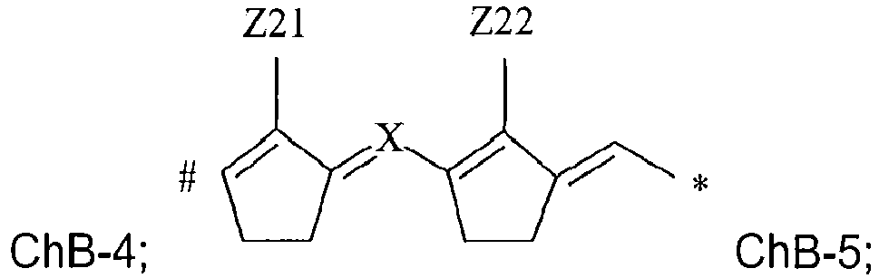


with * indicating the point of attachment between groups B and C; and
wherein, R1 and R5 each independently represent an alkyl group having 1 to 10 carbon atoms; R3 and R7 each independently represent hydrogen, an alkoxy group having 1 to 10 carbon atoms; a thioalkyl group having 1 to 10 carbon atoms; a cyanide group; an ester group having 2 to 6 carbon atoms; an amide group having 2 to 6 carbon atoms; or a halogen; R2, R4, R6 and R8 represent hydrogen; or R2 and R3 may represent the necessary atoms to form a five- or six-membered ring including an oxygen or nitrogen atom directly attached to the carbon atom carrying the R3 group; R4 and R3 may represent the necessary atoms to form a five- or six-membered ring including an oxygen or nitrogen atom directly attached to the carbon atom carrying the R3 group; R6 and R7 may represent the necessary atoms to form a five- or six-membered ring including an oxygen or nitrogen atom directly attached to the carbon atom carrying the R7 group; R8 and R7 may represent the necessary atoms to form a five- or six-membered ring including an oxygen or nitrogen atom directly attached to the carbon atom carrying the R7 group; R9 to R12 each independently represent hydrogen or an alkyl group having 1 to 8 carbon atoms, or R9 and R10 and/or R11 and R12 may represent the necessary atoms to form an alicyclic five- or six-membered ring; R13, R14, R19, R20 each independently represent an alkyl group having 1 to 8 carbon atoms; R15 to R18 each independently represent hydrogen or one of R15 and R16, R16 and R17 or R17 and R18 may represent the necessary atoms to form a benzene ring; R21 to R24 each independently represent hydrogen or one of R21 and R22, R22 and R23 or R23 and R24 may represent the necessary atoms to form a benzene ring; Z1 and Z2 each independently represent an alkyl group having 1 to 6 carbon atoms, a cyanide group, an ester group having 2 to 6 carbon atoms, an amide group having 2 to 6 carbon atoms, an alicyclic group having 5 to 14 carbon atoms, a heterocyclic group having 2 to 14 carbon atoms, an aryl group having 6 to 14 carbon atoms or a heteroaryl group having 2 to 14 carbon atoms; or Z1 and Z2 may represent the necessary atoms to form an alicyclic group having 5 to 14 carbon atoms or a heterocyclic group having 4 to 14 carbon atoms; Z3 to Z6 each independently represent hydrogen or halogen; Z7 and Z7' each independently represent hydrogen, an alkyl group having 1 to 6 carbon atoms, a cyanide group, an ester group having 2 to 6 carbon atoms, an amide group having 2 to 6 carbon atoms, an alicyclic group having 5 to 14 carbon atoms, a heterocyclic group having 2 to 14 carbon atoms, an aryl group having 6 to 14 carbon atoms or a heteroaryl group having 4 to 14 carbon atoms, or Z7 and Z7' may represent the necessary atoms to form an alicyclic group having 5 to 14 carbon atoms or a heterocyclic group having 4 to 14 carbon atoms; Z8 represents hydrogen or if at least one of Z7 and Z7' represents hydrogen Z8 may represent an alkyl group having 1 to 6 carbon atoms, a cyanide group, an ester group having 2 to 6 carbon atoms, an amide group having 1 to 6 carbon atoms or an aryl group having 6 to 14 carbon atoms; Z9, Z10 and Z11 each independently represent hydrogen or halogen; Z12 to Z19 each independently represent hydrogen, an alkyl group having 1 to 6 carbon atoms, an aryl group having 6 to 14 carbon atoms, or a heteroaryl group having 2 to 14 carbon atoms, a cyanide group, an ester group having 2 to 6 carbon atoms, an amide group having 2 to 6 carbon atoms or, one or more of Z12 and Z13, Z15 and Z16 and Z18 and Z19 may represent the necessary atoms to form an alicyclic group having 5 to 14 carbon atoms or a heterocyclic group having 4 to 14 carbon atoms; Z20 represents hydrogen, a halogen, a thioalkyl group having 1 to 8 carbon atoms, a thioaryl group having 5 to 14 carbon atoms, a thioheteroaryl group having 3 to 14 carbon atoms, an aryl group having 6 to 14 carbon atoms, a diarylamino group, an alkylsulfonyl group having 1 to 8 carbon atoms , an arylsulfonyl group having 6 to 14 carbon atoms or a heteroarylsulfonyl group having 2 to 14 carbon atoms; the integers m and n independently have a value of 0 or 1; Z20' and Z20" each independently represent hydrogen, an alkyl group having 1 to 8 carbon atoms, a cyanide group, an ester group having 2 to 8 carbon atoms, an amide group having 2 to 8 carbon atoms or an aryl group having 6 to 14 carbon atoms or Z20' and Z20" may represent the necessary atoms to form an alicyclic group having 5 to 14 carbon atoms or a heterocyclic group having 4 to 14 carbon atoms; Z21 and Z22 each independently represent hydrogen, halogen, a thioalkyl group having 1 to 8 carbon atoms or a thioaryl group having 5 to 14 carbon atoms; X represents nitrogen, a -CH-group or if both Z21 and Z22 represent hydrogen then X may represent a -CR-group with R representing an aryl group having 6 to 14 carbon atoms; Z23 and Z24 each independently represent an alkyl group having 1 to 8 carbon atoms, an aryl group having 6 to 14 carbon atoms or Z23 and Z24 may represent the necessary atoms to form a five- or six-membered ring; Z25 represents hydrogen or an aryl group; with the proviso that when the chain group ChB-4 with the integer m = 0 is combined simultaneously with NucA-1 and NucC-1 that R3 and R6 do not represent hydrogen. - In the above description of the infrared # and * indicate the point of attachment between groups A and B, respectively the point of attachment between groups B and C. The concept of this is exemplified here below by Formula (I) for an infrared dye A-B-C having one anion A-and a dye cation with NucA-1 as the nucleus group A , ChB-1 as the chain group B and NucC-1 as the nucleus group C:

- The infrared dye has an absorption maximum in the infrared region λmax(IR) of larger than 1100 nm, preferably between 1125 nm and 1400 nm, more preferably between 1140 nm and 1300 nm, most preferably between 1150 nm and 1200 nm as measured by absorption spectroscopy in methylene chloride including 6.5 x 10⁻⁶ wt% of methanesulfonic acid based on the total weight of methylenechloride.
- In a preferred embodiment, the infrared dye having a dye cation with the A-B-C chemical structure includes as the nuclei A respectively C, one of the combinations NucA-1 and NucC-1, NucA-2 and NucC-2 and NucA-3 and NucC-3, more preferably one of the combination NucA-1 and NucC-1 and NucA-2 and NucC-2, and most preferably the combination NucA-2 and NucC-2.
- In a particularly preferred embodiment, the infrared dye having a dye cation with the A-B-C chemical structure includes NucA-2 and NucC-2 as the nuclei A respectively C, and ChB-4 as the chain group, more preferably the chain group ChB-4 with Z20 representing a phenyl group, an alkylsulfonyl group containing 1 to 8 carbon atoms, an arylsulfonyl group containing 6 to 14 carbon atoms or a heteroarylsulfonyl group containing 2 to 14 carbon atoms, most preferably the integers m and n have a value of 0.
- In a preferred embodiment of the infrared dye, the integer n has a value of 0, because it was observed that a larger background discoloration was obtained when the integer n has a value of 1.
- In a preferred embodiment of the infrared dye, the integer m has a value of 0 for reasons of chemical stability.
- In a preferred embodiment of the infrared dye, R1 and R5 each independently represent a branched alkyl group, more preferably an α-branched alkyl group and most preferably an asymmetrical α-branched alkyl group. It was observed that the solubility of the infrared dye drastically increases by using a branched alkyl group. The solubility of the infrared dye increases further from a branched alkyl group to an α-branched alkyl group to an asymmetrical α-branched alkyl group.
- The meaning of an asymmetrical α-branched alkyl group is explained using the nucleus NucA-1 according to Formula (II):
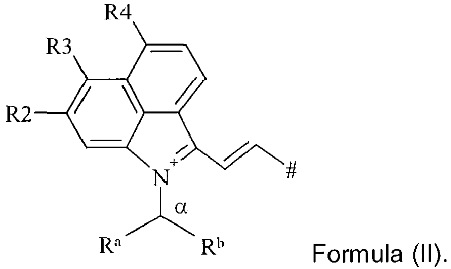
- The groups R1 and R5 in the nucleus NucA-1 respectively the nucleus NucC-1 are preferably represented by CHRaRb , wherein Ra represents hydrogen or an alkyl group including 1 to 4 carbon atoms and Rb represents an alkyl group including 1 to 9 carbon atoms, more preferably Ra represents an alkyl group including 1 to 4 carbon atoms and Rb represents an alkyl group including 1 to 8 carbon atoms, and even more preferably Ra represents an alkyl group including 1 to 4 carbon atoms and Rb represents an alkyl group including 2 to 8 carbon atoms, and most preferably the groups Ra and Rb differ from each other and Ra represents an alkyl group including 1 to 4 carbon atoms and Rb represents an alkyl group including 2 to 8 carbon atoms.
- In a preferred embodiment of the infrared dye, R2, R4, R6 and R8 represent hydrogen, more preferably R2 to R4 and R6 to R8 all represent hydrogen.
- In a preferred embodiment of the infrared dye, R2 to R4 and R6 to R8 all represent hydrogen and R1 and R5 each independently represent a branched alkyl group, more preferably an α-branched alkyl group and most preferably an asymmetrical α-branched alkyl group.
- In a preferred embodiment of the infrared dye, R9 to R12 each independently represent an alkyl group having 1 to 8 carbon atoms.
- In a preferred embodiment of the infrared dye, R15 to R18 each independently represent hydrogen or one of R15 and R16, R16 and R17 or R17and R18 represent the necessary atoms to form an unsubstituted benzene ring.
- In a preferred embodiment of the infrared dye, R21 to R24 each independently represent hydrogen or one of R21 and R22, R22 and R23 or R23 and R24 represent the necessary atoms to form an unsubstituted benzene ring.
- In a preferred embodiment, the infrared dye having a dye cation with the A-B-C chemical structure includes a chain group B selected from the group consisting of ChB-1 to ChB-6.
- In a particularly preferred embodiment, the infrared dye having a dye cation with the A-B-C chemical structure includes NucA-1 and NucC-1 as the nuclei A respectively C, and ChB-4 as the chain group, more preferably the chain group ChB-4 with Z20 representing a phenyl group, a diphenylamino group, an alkylsulfonyl group containing 1 to 8 carbon atoms, an arylsulfonyl group containing 6 to 14 carbon atoms or a heteroarylsulfonyl group containing 2 to 14 carbon atoms, even more preferably the chain group ChB-4 with Z20 representing a phenylsulfonyl group, a para-nitrophenylsulfonyl group, a para-alkoxyphenylsulfonyl group wherein the alkoxy group contains 1 to 6 carbon atoms or a para-chlorophenylsulfonyl group, and most preferably the integers m and n have a value of 0.
- In a preferred embodiment of the infrared dye, Z1 and Z2 represent a cyclic group selected from the group consisting of a cyclopentane-1,3-dione group and a barbituric acid group, preferably a barbituric acid group wherein the nitrogen atoms are substituted by an alkyl group, an aryl group, an alkaryl group or an aralkyl group.
- In a preferred embodiment of the infrared dye, Z3 and Z4 represent hydrogen or chlorine, more preferably hydrogen.
- In a preferred embodiment of the infrared dye, Z3 and Z4 each independently represent hydrogen or chlorine, more preferably Z3 and Z4 represent hydrogen or chlorine, and most preferably Z3 and Z4 represent hydrogen.
- In a preferred embodiment of the infrared dye, Z5 and Z6 each independently represent hydrogen or chlorine, more preferably at least one of Z5 and Z6 represents chlorine.
- In a preferred embodiment of the infrared dye, Z7 and Z7' represent the necessary atoms for forming preferably a barbituric acid group wherein the nitrogen atoms are substituted by an alkyl group, an aryl group, an alkaryl group or an aralkyl group.
- In a particularly preferred embodiment of the infrared dye, Z5 represents chlorine; Z6 represents hydrogen; and Z7 and Z7' represent the necessary atoms for forming preferably a barbituric acid group wherein the nitrogen atoms are substituted by an alkyl group, an aryl group, an alkaryl group or an aralkyl group.
- In a preferred embodiment of the infrared dye, Z9 to Z11 all represent hydrogen or one or two of Z9 to Z10 represents chlorine.
- In one embodiment of the infrared dye, Z12 to Z19 all represent hydrogen.
- In one preferred embodiment of the infrared dye, Z20, Z21 and Z22 all represent chlorine.
- In another preferred embodiment, Z20 represents a phenyl group, a diphenylamino group, an alkylsulfonyl group containing 1 to 8 carbon atoms, an arylsulfonyl group containing 6 to 14 carbon atoms or a heteroarylsulfonyl group containing 2 to 14 carbon atoms, more preferably Z20 represents a phenylsulfonyl group, a para-nitrophenylsulfonyl group, a para-alkoxyphenylsulfonyl group wherein the alkoxy group contains 1 to 6 carbon atoms or a para-chlorophenylsulfonyl group, and most preferably the integers m and n have a value of 0.
- In a preferred embodiment of the infrared dye, Z21 and Z22 each independently represent hydrogen or halogen, more preferably hydrogen.
- In a preferred embodiment of the infrared dye, X represents nitrogen or a -CH-group, more preferably a -CH-group.
- In a preferred embodiment of the infrared dye, Z23 and Z24 both represent a methyl group or ethyl group, more preferably Z23 and Z24 both represent a methyl group.
- In a preferred embodiment of the infrared dye, Z1 and Z2 represent a cyclic group selected from the group consisting of a cyclopentane-1,3-dione group and a barbituric acid group wherein the nitrogen atoms are substituted by an alkyl group, an aryl group, an alkaryl group or an aralkyl group; Z3 and Z4 represent hydrogen; Z5 and Z6 each independently represent hydrogen or chlorine, more preferably at least one of Z5 and Z6 represents chlorine; Z7 and Z7' represent the necessary atoms for forming a barbituric acid group, preferably a barbituric acid group wherein the nitrogen atoms are substituted by an alkyl group, an aryl group, an alkaryl group or an aralkyl group; Z9 to Z11 all represent hydrogen; Z12 to Z19 all represent hydrogen; and Z20 to Z22 all represent chlorine.
- In a preferred embodiment of the infrared dye, the anion to compensate the charge of the cation is selected from the group consisting of chloride, bromide and iodide ions, fluoroalkylsulfonates, arylsulfonates and alkylsulfonates.
- In a more preferred embodiment of the infrared dye, the anion to compensate the charge of the dye cation is selected from the group consisting of a chloride ion, triflate, 1,1,1-trifluoroethanesulfonate, pentafluoroethanesulfonate, nonafluorobutanesulfonate, tosylate, benzenesulfonate, 4-fluorobenzenesulfonate, 1,2,3,4,5-pentafluorobenzenesulfonate, mesylate and butanesulfonate.
- In a preferred embodiment of the infrared dye, the anion to compensate the charge of the dye cation is a non-fluorinated anion. The advantage is that the infrared dyes could be prepared lacking fluorinated anions to compensate the charge of the dye cation without causing problems of dye solubility in an apolar medium or having ecologically undesirable fluorinated waste in the synthesis of the infrared dyes. This is especially the case for the infrared dyes having a dye cation with the A-B-C chemical structure including NucA-1 and NucC-1 as the nuclei A respectively C, wherein R1 and R5 each independently represent a branched alkyl group, more preferably an α-branched alkyl group and most preferably an asymmetrical α-branched alkyl group.
- In a particularly preferred embodiment, the infrared dye having a dye cation with the A-B-C chemical structure includes a non-fluorinated anion to compensate the charge of the dye cation having NucA-1 and NucC-1 as the nuclei A respectively C, wherein R1 and R5 each independently represent a branched alkyl group, more preferably an α-branched alkyl group and most preferably an asymmetrical α-branched alkyl group; and ChB-4 as the chain group, more preferably the chain group ChB-4 with Z20 representing an alkylsulfonyl group containing 1 to 8 carbon atoms, an arylsulfonyl group containing 6 to 14 carbon atoms or a heteroarylsulfonyl group containing 2 to 14 carbon atoms, most preferably the chain group ChB-4 with Z20 representing a phenylsulfonyl group, a para-nitrophenylsulfonyl group, a para-alkoxyphenylsulfonyl group wherein the alkoxy group contains 1 to 6 carbon atoms or a para-chlorophenylsulfonyl group.
- Preferred nucleus groups A are shown in Table 1 without being limited thereto.
Table 1 NA-1 
NA-2 
NA-3 
NA-4 
NA-5 
NA-6 
NA-7 
NA-8 
NA-9 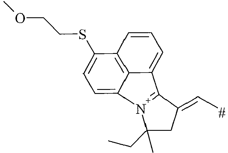
NA-10 
NA-11 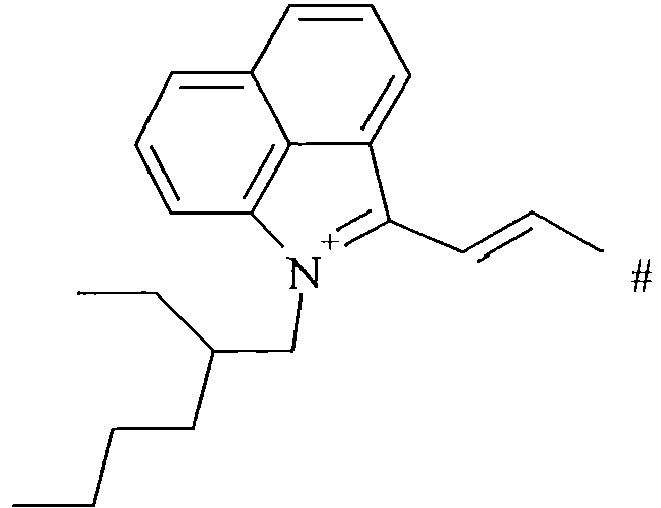
NA-12 
NA-13 
NA-14 
NA-15 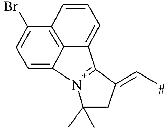
NA-16 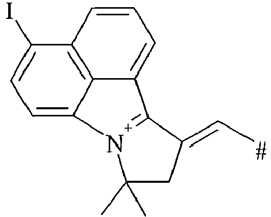
NA-17 
NA-18 
NA-19 
NA-20 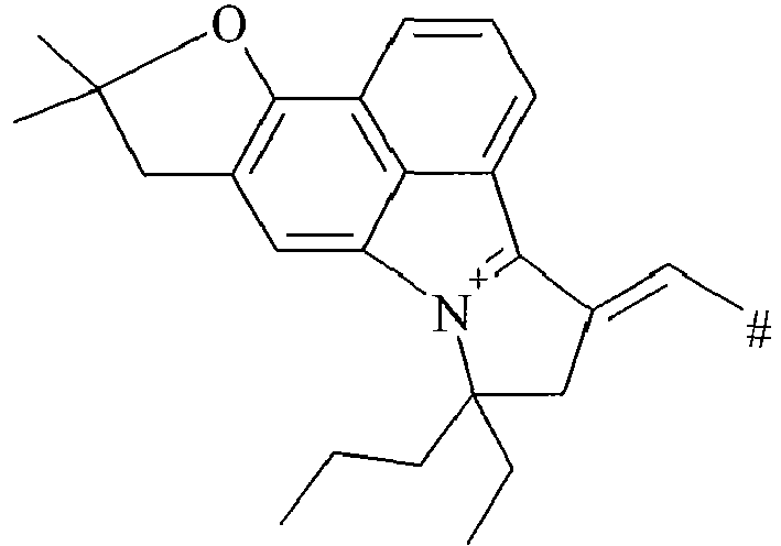
NA-21 
NA-22 
NA-23 
NA-24 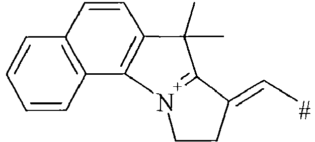
- Preferred chain groups B are shown in Table 2 without being limited thereto.
Table 2 CB-1 
CB-2 
CB-3 
CB-4 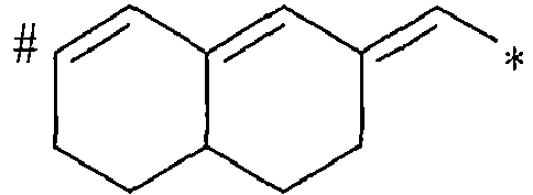
CB-5 
CB-6 
CB-7 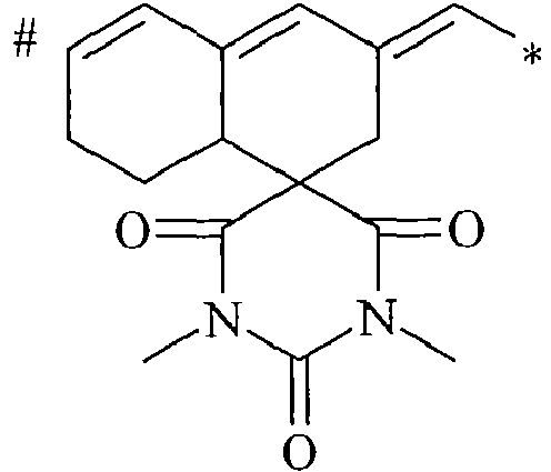
CB-8 
CB-9 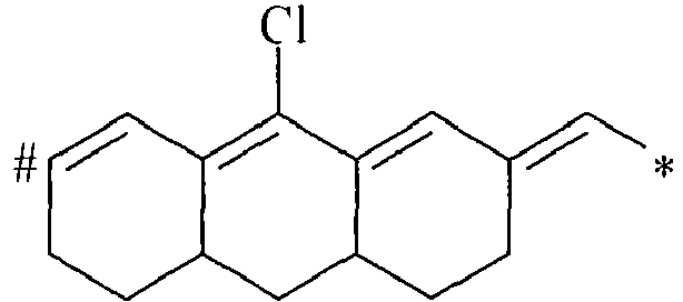
CB-10 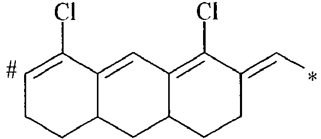
CB-11 
CB-12 
CB-13 
CB-14 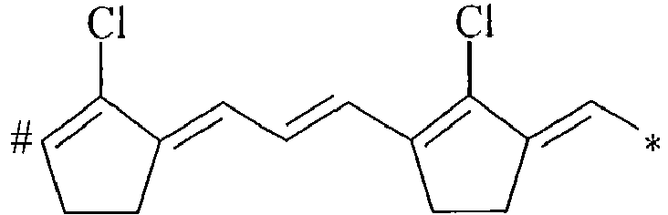
CB-15 
CB-16 
CB-17 
CB-18 
CB-19 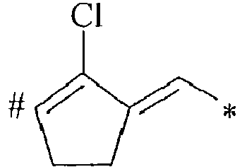
CB-20 
CB-21 
CB-22 
CB-23 
CB-24 
CB-25 
CB-26 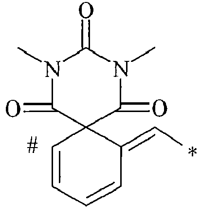
CB-27 
CB-28 
CB-29 
CB-30 
- Preferred nucleus groups C are shown in Table 3 without being limited thereto.
Table 3 NC-1 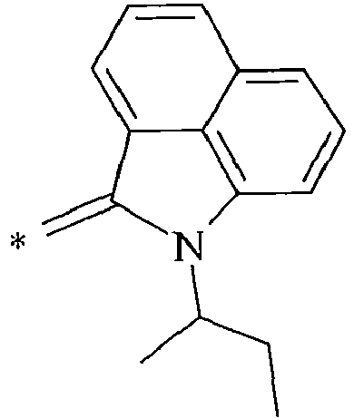
NC-2 
NC-3 
NC-4 
NC-5 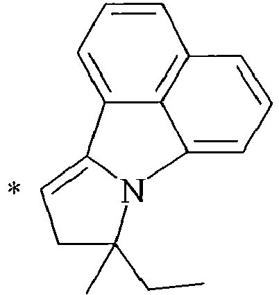
NC-6 
NC-7 
NC-8 
NC-9 
NC-10 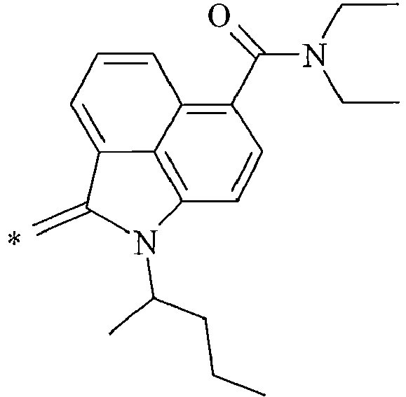
NC-11 
NC-12 
NC-13 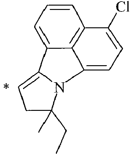
NC-14 
NC-15 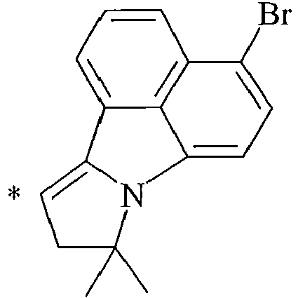
NC-16 
NC-17 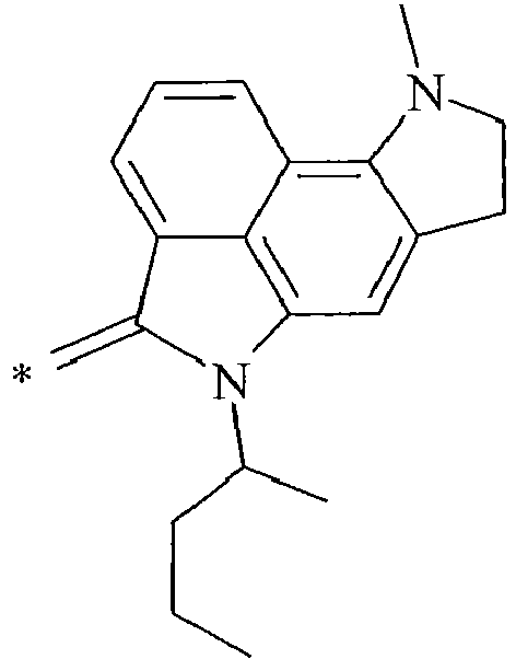
NC-18 
NC-19 
NC-20 
NC-21 
NC-22 
NC-23 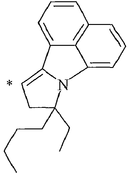
NC-24 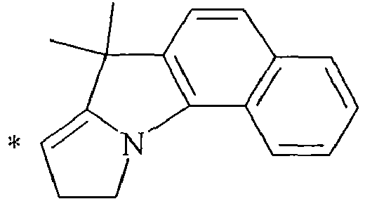
- The synthesis of the infrared dye having a chemical structure A-B-C is well-known for a person skilled in the art of synthesizing dyes. For the sake of clarity, the method of synthesis is exemplified in Example 1 here below.
- In a preferred embodiment of the color laser marked article, the infrared dye IR-2 is selected from the group consisting of quinoline dyes, indolenine dyes, especially a benzo[cd]indoline dye.
- A particular preferred infrared dye is 5-[2,5-bis[2-[1-(1-methylbutyl)benz[cd]indol-2(1H)-ylidene]ethylidene]cyclopentylidene]-1-butyl-3-(2-methoxy-1-methylethyl)- 2,4,6(1H,3H,5H)-pyrimidinetrione (CASRN 223717-84-8), which has an absorption maximum λmax of 1052 nm making it very suitable for a Nd-YAG laser having an emission wavelength of 1064 nm.
- In a preferred embodiment of the color laser marked article, the infrared dye IR-3 is selected from the group consisting of quinoline dyes, indolenine dyes, especially benzo[e]indolenine dyes, and benzo[f]indolenine dyes.
- The color laser markable layer includes a polymeric binder. There is no real limitation on the type of polymeric binder for so far it allows color formation.
- For color laser marking, the laser markable layer preferably includes a polymeric binder comprising vinyl acetate and at least 85 wt% of vinyl chloride based on the total weight of the binder. Particularly preferred polymeric binders are disclosed in EP 2463110 A (AGFA) .
- The polymeric binder in the laser markable layer is preferably a copolymer including at least 85 wt% of a vinyl chloride and 1 wt% to 15 wt% of vinyl acetate, more preferably a copolymer including at least 90 wt% of a vinyl chloride and 1 wt% to 10 wt% of vinyl acetate with all wt% based on the total weight of the binder.
- In a preferred embodiment, the polymeric binder includes at least 4 wt% of vinyl acetate based on the total weight of the binder. The advantage of having at least 4 wt% of vinyl acetate in the polymeric binder is that the solubility of the polymeric binder is drastically improved in preferred coating solvents, such as methyl ethyl ketone.
- In a more preferred embodiment, the polymeric binder consists of vinyl chloride and vinyl acetate.
- If the color laser marked article includes a laser markable layer for producing a black color through carbonization of the polymeric binder then the polymeric binder is preferably selected from polycarbonate (PC), polybutylene terephthalate (PBT), polyvinyl chloride (PVC), polystyrene (PS) and copolymers thereof, such as e.g. aromatic polyester-carbonate, styrene acrylonitrile and acrylonitrile butadiene styrene (ABS).
- The polymeric binder is preferably present in the color laser markable layer in an amount of 3 to 30 g/m2, more preferably in an amount of 5 to 20 g/m2.
- A leuco dye is a compound which changes from essentially colorless to colored when heated, e.g. by laser marking. A number of classes of leuco dyes are preferred for the laser markable layer of the present invention, for example: azines such as oxazines, diazines and thiazines; triarylmethanes such as fluoresceins, rhodamines and rhodols; ketazines; barbituric acid leuco dyes and thiobarbituric acid leuco dyes.
- The leuco dye is preferably present in the color laser markable layer in an amount of 0.5 to 5.0 g/m2, more preferably in an amount of 1.0 to 3.0 g/m2.
- The following reaction mechanisms and leuco dyes are suitable to form a colored dye.
- The reaction mechanism can be represented by:
- Leuco dye-FG → Dye
- A preferred leuco dye (CASRN104434-37-9) is shown in
EP 174054 A - The fragmentation of a leuco dye may be a two-step reaction mechanism represented by:
- Leuco-dye-FG → [Leuco-dye] → Colored Dye
- The fragmentation of a leuco dye may be catalyzed or amplified by acids and acid generating agents. The leuco dyes G-(1) to G-(17) disclosed by
US 6100009 (FUJI) are catalyzed or amplified by polymeric acid generating agents based on A-(1) to A-(52), which are also suitable as acid generating agents in the present invention. - The reaction mechanism can be represented by:
- Leuco-dye + H-donor-FG → Leuco-dye + H-donor → Colored Dye
- A preferred H-donor-FG compound includes an ester group as part of its chemical structure (the rest of the compound is represented by the group T) which by laser heating forms a carboxylic acid group:

- A more preferred H-donor-precursor includes a carbonate group, e.g. a tBOC group, as part of its chemical structure (the rest of the compound is represented by the group T) which by laser heating forms a phenol group:

EP 605149 A - The most preferred H-donor-FG compound is:
HDP.
page 31 ofEP 605149 A - In addition to the H-donor, the fragmentation of the H-donor-FG compound above also leads to the formation of a compound having a melting temperature lower than room temperature (20°C). The formation of such a compound can be used as an additional security feature. After laser marking a laser markable article through a polymeric support, such as a biaxially stretched polyethylene terephthalate polymeric foil, the compound having a melting temperature lower than room temperature may disturb a second laser marking (falsification of a security document) by the formation of visible blisters.
- The reaction mechanism can be represented by:
- Leuco-dye + H-donor-RG → Leuco-dye + H-donor → Colored Dye
- A preferred H-donor-RG compound is capable of forming a compound having an allyl substituted phenol group as part of its chemical structure (the rest of the compound is represented by the group T) by laser heating:

- Preferred H-donor-RG compounds include 4,4'-diallyloxy diphenylsulfone whereof the synthesis is disclosed by
EP 1452334 A (RICOH) . - In contrast to the H-donor-FG compound of
reaction mechanism 2, no compound having a melting temperature lower than room temperature (20°C) is produced by the rearrangement of the H-donor-precursor to a hydrogen donor. - The color formation according to the
mechanisms - The preferred color formation mechanism is the protonation of a leuco dye after fragmentation of the H-donor since it includes both advantages of the blister formation security feature and the enhanced shelf-life stability.
- In a preferred embodiment of the laser markable layer, a combination is used of 4,4'-Bis(tert-butoxycarbonyloxy)diphenylsulfone (CASRN 129104-70-7) as the H-donor-FG compound with the leuco dye crystal violet lactone (CASRN 1552-42-7) for producing a blue color.
- In a preferred embodiment of a laser markable layer for producing a cyan color, the cyan color forming compound has a structure according to Formula CCFC:
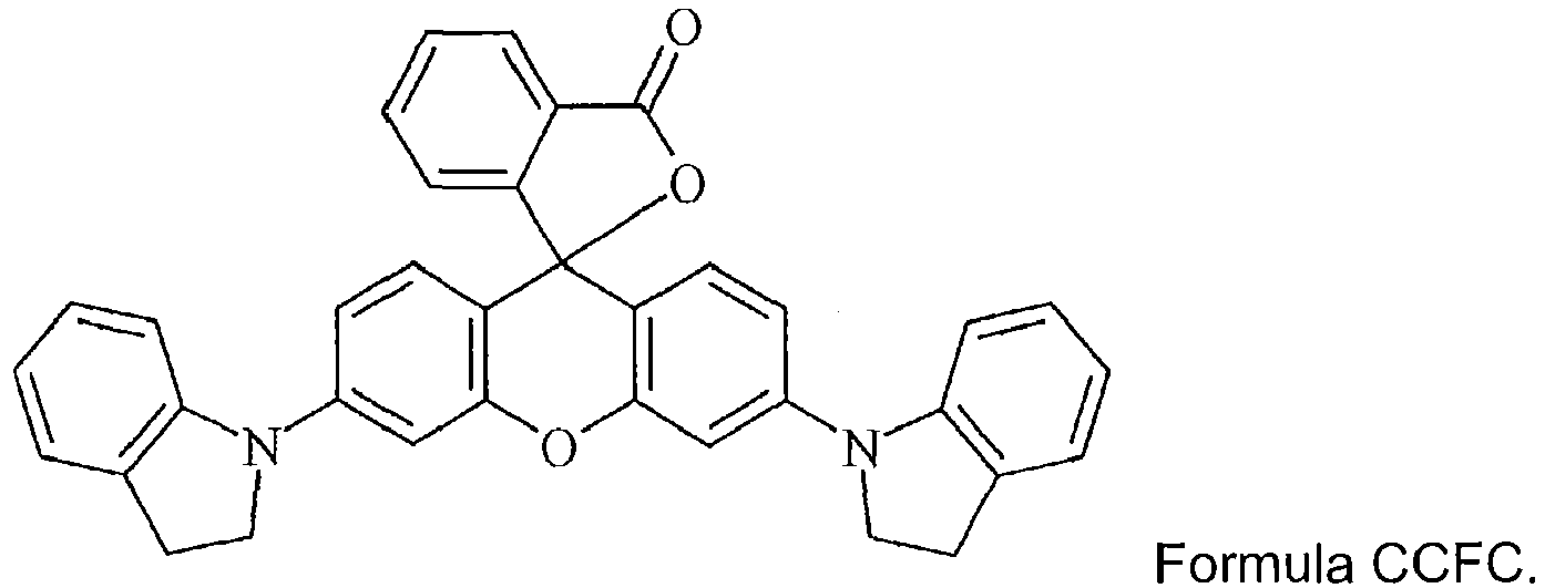
- In a preferred embodiment of a laser markable layer for producing a magenta color, the magenta color forming compound has a structure according to Formula MCFC:

- In one embodiment, the magenta color forming compound has a structure according to Formula MCFC, the R, R', R" may independently represent a linear alkyl group, a branched alkyl group, an aryl or an aralkyl group substituted by at least one functional group containing an oxygen atom, a sulphur atom or a nitrogen atom.
- Particularly preferred magenta color forming compounds include the compounds M-1 to M-6 of Table 4.


- In a very preferred embodiment of a laser markable layer for producing a magenta color, the magenta color forming compound has a structure according to Formula MCFC2:

- In a preferred embodiment of a laser markable layer for producing a red color, the red color forming compound has a structure according to Formula RCFC:

- In a preferred embodiment of a laser markable layer for producing a yellow color, the yellow color forming compound has a structure according to Formula YCFC:
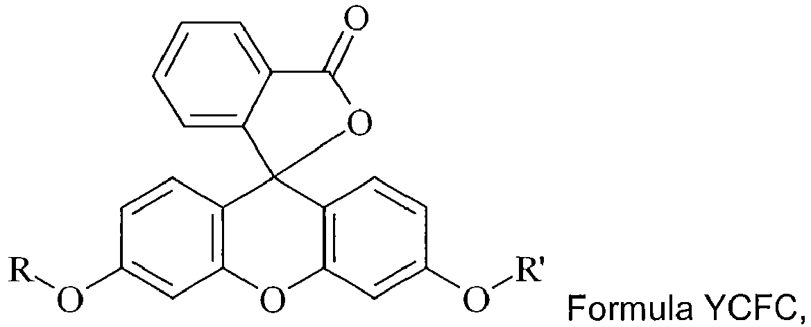
- In one embodiment, the yellow color forming compound has a structure according to Formula YCFC, wherein R and R' independently represent a linear alkyl group, a branched alkyl group, an aryl or an aralkyl group substituted by at least one functional group containing an oxygen atom, a sulphur atom or a nitrogen atom.
- A particularly preferred yellow color forming compound is the compound according to Formula YCFC wherein both R and R' are methyl.
- The leuco dye is preferably present in the laser markable layer in an amount of 0.01 to 2.0 g/m2, more preferably in an amount of 0.1 to 1.0 g/m2.
- The fragmentation of a leuco dye in a color laser markable layer according to the present invention may be catalyzed or amplified by acids and acid generating agents.
- Suitable thermal acid generating agents may be the polymeric acid generating agents based on the ethylenically unsaturated polymerizable compounds A-(1) to A-(52) disclosed by
US 6100009 (FUJI). - Suitable non-polymeric acid generating agents are, for example, the compounds E-(1) to E-(90) disclosed by
US 6100009 (FUJI) lacking the ethylenically unsaturated polymerizable group. - The thermal acid generating agent is preferably present in the amount of 1 to 20 wt%, more preferably 5 to 15 wt% based on the total dry weight of the laser markable layer.
- A color laser markable layer, preferably the outermost color laser markable layer containing the infrared dye IR-3, includes in a preferred embodiment according to the present invention at least one stabilizer, preferably a UV stabilizer.
- Suitable commercially available stabilizers include 6-O-palmitoyl-L-ascorbic acid (CASRN137-66-6) from BASF; TOCOBLEND™ L70 IP (CASRN1406-66-2) from VITABLEND NEDERLAND BV; gallic acid ethyl ester (CASRN831-61-8) from ACROS; 3,6-dithia-1,8-octanediol (CASRN5244-34-8) from ALDRICH; Irganox™ 1035 (CASRN41484-35-9) from CIBA; ADK STAB PEP36 (CASRN80693-00-1) from PALMAROLE; calcium stearate; Tinuvin™ 292 (CASRN 41556-26-7), Tinuvin™ 400 (CASRN 192662-79-6), Tinuvin™ P (CASRN2440-22-4), Tinuvin™ 1130 (CASRN 104810-48-2) and Tinuvin™ 123 (CASRN 122586-52-1) from BASF; Irgastat™ P 18 (CASRN401844-75-5) from CIBA; 1-dibutylacetamido-mercaptotetrazole (CASRN168612-06-4) from Chemosyntha;1-(3,4-dichlorophenyl)-1,2-dihydro-5H-tetrazole-5-thione (CASRN63684-99-1) from NOVASEP; CYASORB™ UV1164 (CASRN2725-22-6) from CYTEC INDUSTRIES BV; Tinuvin™ 400 (CASRN 192662-79-6); 2-(2,4-dihydroxyphenyl)-4,6-bis-(2,4-dimethylphenyl)-s-triazine(CASRN1668-53-7)from Capot Chemical Ltd; 4-[4,6-bis(2-methylphenoxy)-1,3,5-triazin-2-yl]- 1,3-benzenediol (CASRN13413-61-1); Mixxim™ BB/100 (CASRN103597-45-1) from FAIRMOUNT; Hostavin™ 3225-2 DISP XP from CLARIANT; and other benzotriazole and benzophenone compounds.
- Particularly preferred stabilizers include a phenol stabilizer sterically hindered by a ring containing three nitrogen atoms represented by Formula (Stabi-I):
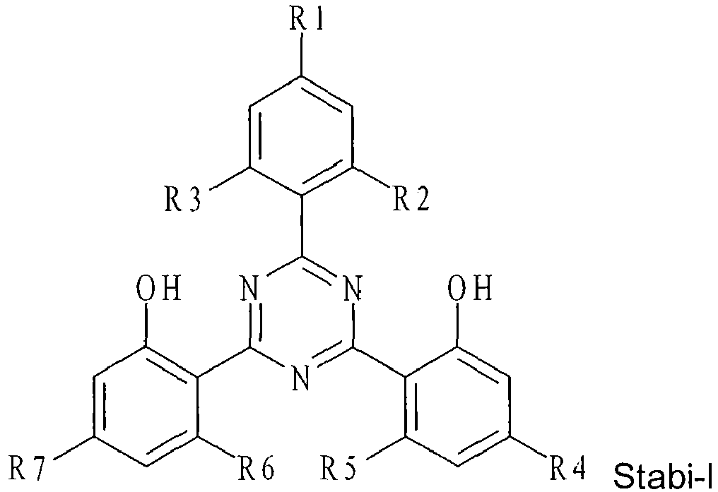

- R1 to R7 is each independently selected from the group consisting of hydrogen, an alkyl group containing 1 to 12 carbon atoms and an alkoxy group containing 1 to 12 carbon atoms;
- R8 represents hydrogen or a halogen atom;
- R9 and R10 is each independently selected from the group consisting of hydrogen, an alkyl group containing 1 to 6 carbon atoms and an aryl group containing 1 to 12 carbon atoms; and
- R11 to R14 is each independently selected from the group consisting of an alkyl group containing 1 to 6 carbon atoms.
- In a preferred embodiment , R1 to R7 is each independently selected from the group consisting of hydrogen, an alkyl group containing 1 to 8 carbon atoms, more preferably an alkyl group containing 1 to 6 carbon atoms, and an alkoxy group containing 1 to 8 carbon atoms, more preferably an alkoxy group containing 1 to 6 carbon atoms.
- In a preferred embodiment , R9 and R10 is each independently selected from the group consisting of hydrogen, an alkyl group containing 1 to 8 carbon atoms, more preferably an alkyl group containing 1 to 6 carbon atoms, and an aryl group containing 1 to 12 carbon atoms, more preferably an alkyl group containing 1 to 10 carbon atoms.
- In a preferred embodiment ,R5 and R6 both represent hydrogen.
- In a preferred embodiment , R11 to R14 all represent methyl and preferably R9 and/or R10 represent methyl or phenyl.
- In a preferred embodiment , R8 represents a chlorine atom.
- In a preferred embodiment , R9 and/or R10 represent a phenyl substituted by an alkyl group or a napthyl group.
- In a particularly preferred embodiment, the color laser markable laminate includes a phenol stabilizer sterically hindered by a ring containing three nitrogen atoms and is selected from the group consisting of IS-1 to IS-4 shown in Table 5.
Table 5 IS-1 
IS-2 
IS-3 
IS-4 
- The stabilizer is preferably present in a laser markable layer, but may also be present in another layer, for example, an outer layer. An outer layer is a layer more distant from the opaque core support than the laser markable on the same side of the opaque core support.
- For coating the laser markable layers, one or more organic solvents may be used. The use of an organic solvent facilitates the dissolution of the polymeric binder and specific ingredients such as the infrared dye.
- A preferred organic solvent is methylethylketone (MEK) because it combines a high solubilizing power for a wide range of ingredients and it provides, on coating the color laser markable layer, a good compromise between the fast drying of the layer and the danger of fire or explosion thereby allowing high coating speeds.
- The color laser markable layers are coated on a support, preferably a polymeric support. If a polymeric support is located between the color laser markable layer and the infrared laser for laser marking it, then the polymeric support is transparent for the light of the infrared lasers in at least that area used for laser marking, preferably the support is a transparent polymeric support. The polymeric supports are also transparent for visual light so that the color formed in the color laser markable layers can be well observed.
- The polymeric support for a laser markable layer is preferably a transparent (bi)axially stretched polymeric support, more preferably a transparent (bi)axially stretched polyester support, and most preferably a transparent (bi)axially stretched polyethylene terephthalate support.
- The transparent polymeric support of the outer laminate is preferably selected from the group consisting of an axially stretched polyethylene terephthalate support, a biaxially stretched polyethylene terephthalate support, an axially stretched polyethylene naphthalate support and a biaxially stretched polyethylene naphthalate support.
- In a very preferred embodiment of the set of laminates, at least the outer laminate includes a biaxially stretched polyethylene terephthalate support as transparent polymeric support.
- The color laser markable layer may be coated directly on the polymeric support or on a subbing layer provided on the polymeric support for improving adhesion of the laser markable layer, thereby making falsification through delamination more difficult.
- Suitable polymeric supports include cellulose acetate propionate or cellulose acetate butyrate, polyesters such as polyethylene terephthalate and polyethylene naphthalate, polyamides, polycarbonates, polyimides, polyolefins, polyvinylchlorides, polyvinylacetals, polyethers and polysulphonamides.
- In the most preferred embodiment, the transparent polymeric support is a biaxially stretched polyethylene terephthalate foil (PET-C foil) which is very durable and resistant to mechanical influences (flexion, torsion, scratches), chemical substances, moisture and temperature ranges. This is especially useful for security documents such as identification cards and credit cards for which the average daily usage has augmented substantially from less than 1 time per week to 4 times per day. The card body has to withstand not only this increased usage, but also the associated storage conditions. Cards are no longer safely tucked away in cabinets at home or seldom-opened wallets, but are now loosely put away in pockets, purses, sport bags etc. - ready for immediate use. PVC (polyvinylchloride) is the most widely used material for plastic cards but has low durability of the card body, resulting in an effective lifetime of only 1-3 years, much lower than the lifetime of the often expensive electronic chips included in the card. Other materials like Teslin™ and ABS are only suitable for very low-end or single-use cards. PC (polycarbonate) can be used for longer-life and more secure ID cards, but has a high production cost and a low resistance to torsion, scratching and chemicals.
- The transparent polymeric support is preferably a single component extrudate, but may also be co-extrudate. Examples of suitable co-extrudates are PET/PETG and PET/PC (PC = polycarbonate).
- Polyester supports and especially polyethylene terephthalate supports are preferred because of their excellent properties of dimensional stability. When polyester is used as the support material, a subbing layer is preferably employed to improve the bonding of layers, foils and/or laminates to the support.
- The manufacturing of PET-C foils and supports is well-known to a person skilled in the art of preparing suitable supports for silver halide photographic films. For example,
GB 811066 - The polyethylene terephthalate is preferably biaxially stretched with a stretching factor of at least 2.0, more preferably at least 3.0 and most preferably a stretching factor of about 3.5. The temperature used during stretching is preferably about 160°C.
- The core support may be a transparent or translucent support, but is preferably an opaque core support, more preferably having a white or a pastel color, most preferably a white color, for allowing easily readable information and viewable color images. The advantage of an opaque white core support is also that a color image is more appealing since colors usually are more vibrant with a white background.
- Preferred opaque white core supports include resin coated paper supports, such as polyethylene coated paper and polypropylene coated paper, and synthetic paper supports such as Synaps™ synthetic paper of Agfa-Gevaert NV.
- Other examples of useful high-quality polymeric supports for the present invention include opaque white polyesters and extrusion blends of polyethylene terephthalate and polypropylene. Also Teslin™ may be used as support.
- Instead of a white support, a white opacifying layer can be coated onto a transparent polymeric support, such as those disclosed above. The opacifying layer preferably contains a white pigment with a refractive index greater than 1.60, preferably greater than 2.00, and most preferably greater than 2.60. The white pigments may be employed singly or in combination. Suitable white pigments include C.I.
Pigment White - Methods to obtain opaque polyethylene terephthalate and biaxially oriented films thereof have been disclosed in, e.g.
US 2008238086 (AGFA). - The transparent polymeric supports and opaque core supports may be provided with one or more subbing layers. This has the advantage that the adhesion between the color laser markable layer and the support is improved.
- Useful subbing layers for this purpose are well known in the photographic art and include, for example, polymers of vinylidene chloride such as vinylidene chloride/acrylonitrile/acrylic acid terpolymers or vinylidene chloride/methyl acrylate/itaconic acid terpolymers.
- The application of subbing layers is well-known in the art of manufacturing polyester supports for silver halide photographic films. For example, the preparation of such subbing layers is disclosed in
US 3649336 (AGFA),GB 1441591 EP 2374602 A (AGFA). - Suitable vinylidene chloride copolymers include: the copolymer of vinylidene chloride, N-tert.-butylacrylamide, n-butyl acrylate, and N-vinyl pyrrolidone (e.g.70:23:3:4), the copolymer of vinylidene chloride, N-tert.-butylacrylamide, n-butyl acrylate, and itaconic acid (e.g. 70:21:5:2), the copolymer of vinylidene chloride, N-tert.-butylacrylamide, and itaconic acid (e.g. 88:10:2), the copolymer of vinylidene chloride, n-butylmaleimide, and itaconic acid (e.g. 90:8:2), the copolymer of vinyl chloride, vinylidene chloride, and methacrylic acid (e.g. 65:30:5), the copolymer of vinylidene chloride, vinyl chloride, and itaconic acid (e.g. 70:26:4), the copolymer of vinyl chloride, n-butyl acrylate, and itaconic acid (e.g. 66:30:4), the copolymer of vinylidene chloride, n-butyl acrylate, and itaconic acid (e.g. 80:18:2), the copolymer of vinylidene chloride, methyl acrylate, and itaconic acid (e.g.90:8:2), the copolymer of vinyl chloride, vinylidene chloride, N-tert.-butylacrylamide, and itaconic acid (e.g. 50:30:18:2). All the ratios given between brackets in the above-mentioned copolymers are ratios by weight.
- In a preferred embodiment, the subbing layer has a dry thickness of no more than 2 µm or preferably no more than 200 mg/m2.
- The color laser marked article may include additional layers foils. Such an additional layer can, for example, be an adhesive layer, a layer including UV stabilizers for protecting color images against bleaching or a layer containing an infrared antihalation dye for improving the sharpness of a color image.
- An adhesive foil may be interlaminated between two color laser markable layers in order to make falsification by delamination more difficult. Instead of an adhesive foil, an adhesive layer may be applied as a layer on top of a color laser markable layer. However, the use of an adhesive foil instead of an adhesive layer has the advantage is that an adhesive foil does not extract some of the more soluble ingredients in the laser markable layer like an adhesive layer can do upon coating and drying. Variation in the concentration of the soluble ingredients leads to inconsistencies in the color production during laser marking.
- Suitable adhesive foils include pressure-sensitive and thermo-sensitive adhesive foils. A range of so-called hot melt foils are well-known to one skilled in the art of security films and security documents.
- A preferred hot melt foil in the present invention is a polyurethane foil. Suitable commercially available hot melt foils include Platilon™ ID5051, a 35 µm polyurethane foil available from Epurex. Other suitable hot melt foils are Scapa™ Thermofoil G160 and G161.
- Another preferred adhesive foil is PETG. Contrary to biaxially oriented polyethylene terephthalate, a non-oriented PETG foil softens rapidly near the glass transition temperature and can thus also be used for adhesive purposes.
- In a preferred embodiment, the adhesive foil is made of a non-chlorinated polymer. Adhesive foils based on a chlorinated polymer may cause background discoloration. Preferred adhesive foils include polyester, polyester urethane, polyether urethane or polyolefin hot melt foils.
- If the adhesive is applied as an adhesive layer on a color laser markable layer or on polymeric support, this may be performed by methods such as solvent coating, casting, or hot melt extrusion.
- Suitable thermo adhesive compositions are disclosed in
WO 2009/063058 (AGFA). Preferred thermo adhesive layers are based on a hydroxyl-functional, partially-hydrolized vinyl chloride/vinyl acetate resin such as, for example, available under the trade name of UCAR(TM) VAGD Solution vinyl resin from Dow Chemical Company. - The adhesive foil preferably has a thickness smaller than 65 µm, more preferably smaller than 50 µm and most preferably smaller than 40 µm.
- The color laser marked articles include preferably one or more security features to increase the difficulty for falsifying the document.
- To prevent forgeries of e.g. identification documents, different means of securing may be used. One solution consists in superimposing lines or guilloches on an identification picture such as a photograph. Other solutions consist in adding security elements such as information printed with ink that reacts to ultraviolet radiation, micro-letters concealed in an image or text etc.
- Suitable other security features such as anti-copy patterns; guilloches; line patterns; endless text; miniprint; microprint; nanoprint; rainbow coloring; barcodes including 2D-barcodes; colored fibres; fluorescent fibres and planchettes; fluorescent pigments including fluorescent hi-lites; OVD (Optically Variable Device) and DOVID (Diffractive Optically Variable Image Device) such as holograms, 2D and 3D holograms, holograms with kinematic effects like Kinegrams™; overprint; relief embossing; perforations; metallic pigments; magnetic material; metameric colors; microchips such as RFID chips; images made with OVI (Optically Variable Ink) such as iridescent and photochromic ink; images made with thermochromic ink; phosphorescent pigments and dyes; watermarks including single tone, duotone and multitone watermarks; ghost images and security threads.
- All materials used in the following examples were readily available from standard sources such as Aldrich Chemical Co. (Belgium) and Acros (Belgium) unless otherwise specified. The water used was deionized water.
- CCE is Bayhydrol H 2558, a anionic polyester urethane (37.3%) from BAYER.
Resorcinol from Sumitomo Chemicals.
Par is a dimethyltrimethylolamine formaldehyde resin from Cytec industries.
PAR-sol is a 40wt% aqueous solution of Par.
PEA is Tospearl™ 120 from Momentive Performance materials.
PEA-sol is a 10wt% (50/50) aqueous/ethanol dispersion of PEA.
Dowfax™2A1 from Pilot Chemicals C is a Alkyldiphenyloxide disulfonate (4.5%wt%).
DOW-sol is a 2.5wt% solution of Dowfax™2A1 in isopropanol.
Surfynol™ 420 from Air Products is a non ionic surfactant.
Surfynsol is a 2.5wt% solution of Surfynol™ 420 in isopropanol. - MEK is an abbreviation used for methylethylketone.
Solvin™ 557RB is a vinylchloride-vinylacetate copolymer with 11 % vinyl acetate, provided by SOLVAY.
SolvinSol is a 12.5 wt% solution of Solvin™ 557RB in MEK.
Vinnol™ H40/55 is a copolymer of 62 wt% vinyl chloride and 38 wt% of vinyl acetate provided by Wacker AG. - VinnolSol is a 12.5 wt% solution of Vinnol™ H40/55 in MEK.
- HDP is the hydrogen donor-precursor CASRN 129104-70-7 prepared according to the synthesis given on
page 31 ofEP 605149 A - BLD is crystal violet lactone (CASRN 1552-42-7) available from YAMADA CHEMICAL CO.
- MLD is a bisindolylphthalide leuco dye (CASRN50292-95-0) available as Pergascript™ Red 16B from BASF.
- YLD is 3',6'-dimethoxyfluoran (CASRN36886-76-7) available from TCI Europe NV.
- IR-1Asol is a 0.15 wt% solution in MEK of the infrared dye IR-1A.
- IR-1Csol is a 0.15 wt% solution in MEK of the infrared dye IR-1C.
- IR-2 is a 0.15 wt% solution in MEK of the infrared dye CASRN 223717-84-8 having an absorption maximum at 1052 nm and was prepared in the same manner as disclosed by paragraphs [0150] to [0159] of
EP 2463109 A (AGFA) . - IR-3 was synthesized as follows via the intermediates IR-INT1 and IR-INT2:
-
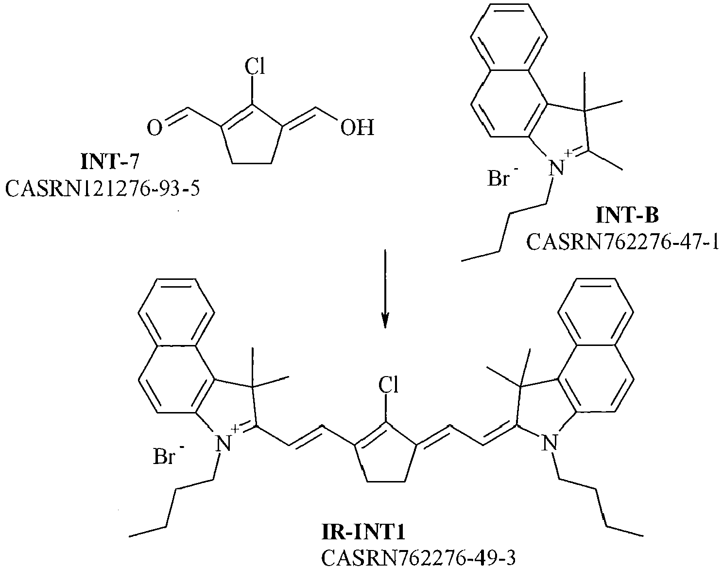
- The synthesis of the intermediate INT-7 was performed as disclosed for infrared dye IR-1B.
The synthesis of the intermediate INT-B was performed as follows. 1 mol of 1,1,2-trimethyl-1H-benzo[e]indole (CASRN41532-84-7) and 2 mol of n-butyl bromide were stirred in 0.5 l sulfolane for four hours at 100°C. INT-B was filtered, washed with ethyl acetate and dried. The yield was 61%. To a stirred mixture of INT-7 (4.75 g; 30 mmol) and INT-B (20.8 g; 60 mmol) in ethanol (100 mL) at room temperature were added consecutively triethylamine (12.1 g; 120 mmol) and acetic acid anhydride (12.2 g; 120 mmol). After heating to 50 °C for 1 hour, the reaction mixture was cooled to 20 °C and isopropanol (100 mL) was added. After 1 hour the precipitated IR-absorber was isolated by filtration, washed with EtOAc (20 mL) and dried in vacuo. Yield (crude) of IR-INT1 was 16 g (73%). The absorption maximum of IR-INT1 measured in methanol was 844 nm. -

- To a stirred suspension of IR-INT1 (16 g; 22 mmol) in acetonitrile (200 mL) was added potassium nonafluorobutanesulfonate (CASRN29420-49-3 from TCI Europe N.V.; 8.1 g; 24 mmol) and this mixture was heated at 70 °C for 15 minutes. After cooling to room temperature, water (100 mL) was drop wise added and after stirring for 2 hours the precipitated IR-absorber was isolated by filtration, washed consecutively with a mixture of acetonitrile /
water 2/1 (20 mL), methyl tert. butylether (MTBE) (20 mL) and dried in vacuo. The yield of IR-INT2 was 14 g (67%). The absorption maximum of IR-INT2 measured in methanol was 844 nm. -

- To a stirred suspension of IR-INT2 (1.65 g; 1,73 mmol) in methanol (15 mL) under nitrogen at room temperature is added sodium benzenesulfinate (CASRN873-55-2 from Aldrich; 0.297 g; 1,81 mmol). After stirring for 2 hours the precipitated IR-absorber was isolated by filtration, washed with MTBE (5 mL) and dried in vacuo. The yield of IR-3 was 1.2 g (65%). The absorption maximum measured in methanol was 910 nm. The absorption maximum of IR-3 measured in CH2Cl2 including 6.5 x 10⁻⁶ wt% of methanesulfonic acid was 923 nm.
- IR-3sol is a 0.15 wt% solution in MEK of the infrared dye IR-3.
- CORE is a 500 µm opaque PETG core available as PET-G 500 type 9311 from WOLFEN.
- PETG TR is a 35 µm thick transparent PETG support available as type - PET-G transparent 35 µm from AMCOR.
- The optical density was measured in reflection using a spectrodensitometer Type Macbeth TR924 using a visual filter.
- The absorption maxima can be easily determined by absorption spectroscopy using a standard spectrophotometer capable of measuring the absorption between 300 and 1500 nm. Here a SHIMADZU UV-2101 PC spectrophotometer was used to measure the absorption maxima of an infrared dye dissolved in methylene chloride including 6.5 x 10⁻⁶ wt% of methanesulfonic acid based on the total weight of methylenechloride. No methanesulfonic acid was used if the absorption spectrum was recorded in methanol or a solvent mixture therewith. The concentration of the infrared dye was adjusted according to the specific absorption characteristics of a dye so that an accurate measurement by the spectrophotometer was possible and not out of scale.
- λmax(IR) is the wavelength of the absorption maximum in the infrared spectrum from 700 to 1500 nm.
- λmax(VIS) is the wavelength of the absorption maximum in the visual spectrum from 400 to 700 nm.
- For coated laser markable layers, the absorption between 250
nm tot 1500 nm was measured in steps of 10 nm using a PerkinElmer LAMBDA 950 UV/Vis/NIR Spectrophotometer. - The ratio IR/VIS is determined by dividing the absorption at λmax(IR) by the absorption at λmax(VIS). For acceptable background discoloration the ratio IR/VIS should preferably be at least 3.5 and more preferably at least 7.0.
- A Dmin-area is an area which was not laser marked, i.e. a background density area. The difference in optical density between a Dmin area before and after an at least partial exposure of the method for preparing a color laser marked article is used as a criterion for evaluation of the increase in Dmin as shown in Table 6.
Table 6 Dmin increase Criterion Minimal Increase in optical density of 0 .00 up to 0.20 Moderate Increase in optical density of more than 0.20 up to 0.40 Strong Increase in optical density of more than 0.40 up to 0.60 Very strong Increase in optical density of more than 0.60 - The % inactivation of the infrared dye is determined using the maximum optical densities (Dmax) before and after an at least partial exposure of the method for preparing a color laser marked article. The % Inactivation is calculated according to the mathematical formula:
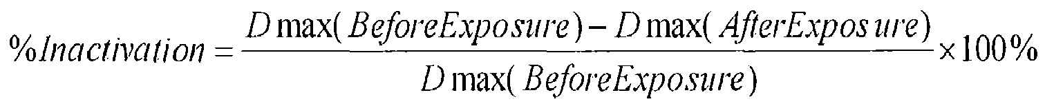
- The criteria used for evaluation are shown in Table 7.
Table 7 % Inactivation Criterion Minimal 0 to < 5% Moderate 5 to < 20% Strong 20% to 40% Very strong > 40% - This example illustrates the synthesis of novel infrared dyes IR-1 for facilitating the method for preparing a color laser marked article in accordance with the present invention.
- The synthesis of IR-absorber IR-1 was carried out as described below by preparing firstly the intermediates INT-1 to INT-6.
-

- The starting materials cyclohexenone (CASRN930-68-7) and N,N-dimethyl barbituric acid (CASRN769-42-6) were commercially available compounds from TCI EUROPE N.V and Aldrich.
- A mixture of cyclohexenone (48 g; 0.5 mol) and N,N-dimethyl barbituric acid (85.8 g; 0.55 mol) in water (0.5 L) was vigorously stirred at room temperature overnight. The white precipitate was filtered, digested with water (1.0 L) and dried in vacuo at 50 °C. Yield of INT-1 (white powder): 111 g (88%).
-

- A mixture of INT-1 (37.8 g; 0.15 mol) and acrolein (containing 10% water and 0,1% hydroquinone) (14.0 g; 0.22 mol) in water (90 mL) and tetrahydrofuran (THF) (30 mL) was vigorously stirred at room temperature overnight. After addition of water (100 mL), stirring was continued for 1 hour. The white precipitate was filtered, digested with water (350 mL), filtered and dissolved in CH2Cl2 (200 mL). After washing the CH2Cl2 layer with water (30 mL) and drying over MgSO4 (5 g), the CH2Cl2 layer was concentrated in vacuo (rotavap). Yield of INT-2 (sticky white powder): 38 g (82%).
-
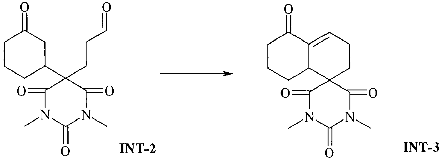
- To a stirred solution of INT-2 (37 g; 0.12 mol) in CH2Cl2 (550 mL) was added a solution of methanesulfonic acid (5,76 g) in tetrahydrofuran (THF) (120 mL) at room temperature. After stirring for 24 hours, the mixture was consecutively extracted with a solution of NaHCO3 (20 g) in water (200 mL), a solution of NaHCO3 (7 g) in water (200 mL) and a solution of NaCl (10 g) in water (200 mL). After drying over Mg2SO4 (5 g), the organic layer was concentrated in vacuo (rotavap). Yield of INT-3 (sticky white powder): 30 g (85%).
-

- To a stirred solution of NMF (4.06 g; 0.03 mol) in methylacetate (40 mL) was added POCl3 (6.9 g; 0.045 mmol) at 0°C. After stirring for 15 minutes, INT-3 (4.1 g; 0.014 mol) was added in small portions over a 15 minute period and then this mixture was heated to reflux (bath temperature 90°C) for 2 hours. After cooling on an ice bath, the blue colored solution (containing INT-4) was poured into a cooled, well stirred solution of NaHCO3 .3aq (30,5 g) in water (50 mL). After gradual warming the mixture to room temperature over a 1 hour period, the organic phase was separated, washed with saturated NaCl in water (10 mL), dried over Mg2SO4 (5 g) and concentrated (viscous dark oil, ca. 10 g). After redissolving this oil in a mixture of acetic acid (42 mL) and methanol (142 mL), water (210 mL) was added while vigorously stirring. The formed red-brown precipitate was collected by filtration, digested with water (50 mL), filtered and dried in vacuo in the presence of solid KOH. Yield of red-brown powder: 2.59 g (41 %). The absorption maximum (in methanol) was found to be 443 nm.
- According to LC-MS analysis, the product was mainly a mixture of 2 isomers (ratio: +/- 15:1) of INT-5 and INT-5' (or vice versa). Since this is inconsequential for the synthesis of IR-1A, the mixture was used directly in the next step.
-

- The synthesis of intermediate INT-6 was performed as disclosed in [0157] of
EP 2463109 A (AGFA). - A suspension of INT-5/INT-5' (2.27g; 5 mmol) and INT-6 (3.65 g; 10 mmol) was stirred overnight at room temperature in a mixture of methanol (25 mL) and CH2Cl2 (25 mL). The green-brown solids were isolated by filtration, digested in methanol (25 mL) for 15 minutes at room temperature, filtered and dried in vacuo. Yield of IR-1A (green-brown powder): 0.57 g (22%).
- The absorption maximum of IR-1A measured in methanol was found to be 1132 nm. The absorption maximum of IR-1A measured in CH2Cl2 including 6.5 x 10⁻⁶ wt% of methanesulfonic acid was 1154 nm.
-

- The intermediate INT-6 was prepared in the same manner as above for infrared dye IR-1A.
- The synthesis of intermediate INT-7 was performed as follows. 10 mol of dimethylformamide and 3 mol phosphoryl chloride were heated up to 65°C. Then 1 mol of cyclopentanon was dropped to this mixture. After one hour of stirring at 60°C, the reaction mixture was poured into 2 l water containing 7 mol sodium acetate. INT-7 was filtered and dried. The yield was 60%.
- To a stirred mixture of INT-7 containing 23% water (10.3 g; 0.05 mol) and INT-6 (36.5 g; 0.1 mol) in methanol (250 mL) was added a mixture of acetic acid (10,1 g; 0,1 mol) and triethylamine (18 g; 0,3 mol) over a 1 hour period. Stirring (under nitrogen) was continued for 1 hour at room temperature. The black precipitate was filtered and digested consecutively with 2x 20 mL of methanol and 2x 50 mL of methyl tertiary butylether (MTBE) and dried in vacuo. Yield of IR-1B (black powder): 27 g (74.6%).
- The absorption maximum measured in methanol was 1040 nm. The absorption maximum of IR-1B measured in CH2Cl2 including 6.5 x 10⁻⁶ wt% of methanesulfonic acid was 1062 nm. This infrared dye IR-1B is excluded from the scope of the present invention.
-

- To a stirred suspension of IR-1B (500 mg; 0.69 mmol) in a mixture of ethanol (9 mL) and water (1 mL) at room temperature was added sodium benzenesulfonate (CASRN873-55-2; 135 mg; 0.82 mmol). After stirring for 15 minutes, the black precipitate was filtered, digested with a mixture of ethanol (4.5 mL) and water (0.5 mL) and dried in vacuo. The yield of IR-1C (black powder) was 467 mg (81 %).
- The absorption maximum measured in methanol was 1104 nm. The absorption maximum of IR-1C measured in CH2Cl2 including 6.5 x 10⁻⁶ wt% of methanesulfonic acid was 1120 nm.
-

- The synthesis of INT-8 was performed as in Sarmistha Halder Sinha, et al., European Journal of Medicinal Chemistry 54 (2012) 647-659.
- The synthesis of INT-9 from dimedone was performed as described in Manfred Pulst, Bernd Hollborn, Manfred Weissenfels Journal f. prakt. Chemie, Band 321, Heft 4, 1979, S. 671-674
- To a stirred suspension of INT-8 (81 mg; 0.25 mmol) and INT-9 (23 mg; 0.1 mmol) in a mixture of methanol (1 mL) and CH2Cl2 (1 mL) were added acetic acid (60 mg; 1,0 mmol) and indoline (25 mg; 0,2 mmol) at room temperature. After stirring over night, the precipitated IR-1D was filtered, digested consecutively with methanol (1 mL), a mixture of methanol (0,8 mL) and CH2Cl2 (0.2 mL) and dried in vacuo. The yield of IR-1D (black powder) was 10 mg (14%)
- The absorption maximum measured in 1:1 mixture methanol / CH2Cl2 was found to be 1189 nm.
- This example illustrates the manufacturing and use of a set of color laser markable laminates for preparing a color laser marked article in accordance with the invention.
- A coating composition SUB-1 was prepared by mixing the components according to Table 8 using a dissolver.
Table 8 wt% of components SUB-1 deionized water 76.66 CCE 18.45 Resorcinol 0.98 PAR-sol 0.57 PEA-sol 0.68 DOW-sol 1.33 Surfynsol 1.33 - A 1100 µm thick polyethylene terephthalate sheet was first longitudinally stretched and then coated on one side with the coating composition SUB-1 to a wet thickness of 10 µm. After drying, the longitudinally stretched and coated polyethylene terephthalate sheet was transversally stretched to produce a single side subbed 63 µm thick sheet PET1, which was transparent and glossy.
- A 1100 µm thick polyethylene terephthalate sheet was first longitudinally stretched and then coated on both sides with the coating composition SUB-1 to a wet thickness of 10 µm. After drying, the longitudinally stretched and coated polyethylene terephthalate sheet was transversally stretched to produce a double side subbed 63 µm thick sheet PET2, which was transparent and glossy.
- The coating compositions BCOL1 and YCOL1 were prepared in the same way by mixing the components according to Table 9 using a dissolver.
Table 9 wt% of components BCOL1 YCOL1 MEK 16.88 4.11 SolvinSol 60.00 --- VinSol --- 75.00 IR-2 20.00 --- IR-1Asol --- 18.22 HDP 1.63 1.63 BLD 1.50 --- YLD --- 1.04 - The coating composition BCOL1 was coated with an Elcometer Bird Film Applicator (from ELCOMETER INSTRUMENTS) on one side of the PET-C support PET2 at a coating thickness of 100 µm and subsequently dried for 2 minutes at 20°C on the film applicator and for a further 15 minutes in an oven at 75°C.
- Then the coating composition YCOL1 was coated with an Elcometer Bird Film Applicator (from ELCOMETER INSTRUMENTS) on the opposite side of the PET-C support PET2 coated with BCOL1 at a coating thickness of 100 µm and subsequently dried for 2 minutes at 20°C on the film applicator and for a further 15 minutes in an oven at 75°C to deliver the color laser markable inner laminate IL1.
- The coating composition MCOL1 was prepared by mixing the components according to Table 10 using a dissolver.
Table 10 wt% of components MCOL1 MEK 0.07 SolvinSol 53.65 IR-3sol 40.7 HDP 2.13 MLD 3.45 - The coating composition MCOL1 was coated with an Elcometer Bird Film Applicator (from ELCOMETER INSTRUMENTS) on the subbed side of the PET-C support PET1 at a coating thickness of 100 µm and subsequently dried for 2 minutes at 20°C on the film applicator and for a further 15 minutes in an oven at 75°C to deliver the color laser markable outer laminate OL1.
- An assembly was made of, in order, a white opaque core support CORE, the color laser markable inner laminate IL1, a 35 µm PETG TR foil, and the color laser markable outer laminate OL1, wherein the side coated with YCOL1 of the color laser markable inner laminate IL1 faces the white opaque core support CORE and wherein the side coated with MCOL1 of the color laser markable outer laminate OL1 faces the 35 µm PETG TR foil.
- The assembly was then laminated into a color laser markable article LMA1 using an Oasys™ OLA6/7 plate laminator with the settings: LPT = 130°C, LP = 40, Hold = 210 sec, HPT = 130°C , HP = 40 and ECT = 50°C.
- The laser markable article LMA1 was then laser marked with three infrared lasers of different emission wavelength.
- A first optically pumped semiconductor laser emitting at 920 nm (Genesis MX 920-4000 MTM from COHERENT) was used for producing a magenta colored wedge of 1cm x 1cm square boxes of increasing optical density up to a maximum optical density of 1.02 in the laser markable layer coated from MCOL1. The laser was used at a power level of 4.5 W (29.5 A), a dither of 0.025, a scan speed of 100 mm/s and at a pulse repetition rate of 1.2 kHz. The effective power was 70 to 90 mW.
- A second optically pumped semiconductor laser emitting at 1064 nm (Genesis MX 1064-10000 MTM from COHERENT) was used for producing a blue colored wedge of 1 cm x 1cm square boxes of increasing optical density up to a maximum optical density of 1.38 in the laser markable layer coated from BCOL1. The laser was used at a power level of 4.0 W (21.8 A), a dither of 0.025, a scan speed of 100 mm/s and at a pulse repetition rate of 1.2 kHz. The effective power was 60 to 85 mW.
- A third optically pumped semiconductor laser emitting at 1154 nm (Genesis MX 1154-6000 MTM from COHERENT) was used for producing a yellow colored wedge of 1 cm x 1 cm square boxes of increasing optical density up to a maximum optical density of 0.55 in the laser markable layer coated from YCOL1. The laser was used at a power level of 2.25 W (19.4 A), a dither of 0.025, a scan speed of 100 mm/s and at a pulse repetition rate of 1.2 kHz. The effective power was 25 to 40 mW.
- No color contamination was observed in the different colored wedges. This means that none of the three lasers caused any color formation in a laser markable layer other than the one for which it was intended. For example, the 920 nm laser caused no blue respectively yellow color formation in the laser markable layers coated from BCOL1 and YCOL1.
- The color laser marked articles were then exposed to Xenon light at 765 W/m2 using so-called L-filters which cut off all light below a certain wavelength. For example, when using a L445-filter then all the light below 445 nm is blocked from reaching the color laser marked article. Several properties were measured after the at least partial exposure of the laser marking method according to the present invention as shown in Table 11.
Table 11 Cut-off Filter Dmin increase % Inactivation of IR dye at : 920 nm 1064 nm 1154 nm L295 Very strong Moderate Minimal Minimal L345 Very strong Moderate Minimal Minimal L400 Moderate Strong Moderate Minimal L445 Moderate Strong Moderate Minimal L495 Moderate Strong Minimal Minimal L550 Minimal Very strong Moderate Minimal L610 Minimal Moderate Moderate Minimal L695 Minimal Moderate Moderate Minimal - Table 11 shows that color laser marked articles exposed using an L-filter of 550 nm or higher exhibited minimal Dmin increase, while the infrared dyes of at least two color laser markable layers were partially inactivated. The example using the L550 cut-off filter exhibited minimal Dmin increase, while the three color laser markable layers were inactivated to a different degree making a succesfull falsification extremely difficult, especially if this inactivation would be performed on some parts of the color laser marked article and not in others.
-
Figure 1 shows the absorption spectrum from 700 to 1500 nm measured on the color laser marked article before exposure (solid line) and after an exposure though L495 cut-off filter (dotted line). One clearly observes a partial inactivation of infrared dyes IR-1 and IR-3. - This example illustrates the importance of the order of the color laser markable layers in a color laser markable article, more particularly the importance of the order of the wavelengths of the infrared absorption maximum of the infrared dyes for color contamination.
- Color laser markable inner laminates IL1 and color laser markable outer laminates OL1 were prepared in the same manner as in Example 2.
- An assembly was made of, in order, a white opaque core support CORE, the color laser markable inner laminate IL1, a 35 µm PETG TR foil, and the color laser markable outer laminate OL1, wherein the side coated with YCOL1 of the color laser markable inner laminate IL1 faces the white opaque core support CORE and wherein the side coated with MCOL1 of the color laser markable outer laminate OL1 faces the 35 µm PETG TR foil. The assembly was then laminated into a color laser markable article LMA5 using an Oasys™ OLA6/7 plate laminator with the settings: LPT = 130°C, LP = 40, Hold = 210 sec, HPT = 130°C , HP = 40 and ECT = 50°C.
- An assembly was made of, in order, a white opaque core support CORE, the color laser markable inner laminate IL1, a 35 µm PETG TR foil, and the color laser markable outer laminate OL1, wherein the side coated with BCOL1 of the color laser markable inner laminate IL1 faces the white opaque core support CORE and wherein the side coated with MCOL1 of the color laser markable outer laminate OL1 faces the 35 µm PETG TR foil. The assembly was then laminated into a color laser markable article LMA6 using an Oasys™ OLA6/7 plate laminator with the settings: LPT = 130°C, LP = 40, Hold = 210 sec, HPT = 130°C , HP = 40 and ECT = 50°C.
- An assembly was made of, in order, a white opaque core support CORE, the color laser markable laminate OL1, the color laser markable laminate IL1, a 35 µm PETG TR foil, wherein the side coated with MCOL1 of the color laser markable laminate OL1 faces the white opaque core support CORE and wherein the side coated with BCOL1 of the color laser markable laminate IL1 faces the 35 µm PETG TR foil. The assembly was then laminated into a color laser markable article LMA7 using an Oasys™ OLA6/7 plate laminator with the settings: LPT = 130°C, LP = 40, Hold = 210 sec, HPT = 130°C, HP = 40 and ECT = 50°C.
- The absorption maximum wavelength order of the infrared dyes in the color laser markable articles LMA2 to LMA4 is illustrated by Table 12.
Table 12 LMA2 LMA3 LMA4 Outermost surface Outermost surface Outermost surface λmax(IR-3) λmax(IR-3) λmax(IR-2) λmax(IR-2) λmax(IR-1) λmax(IR-1) λmax(IR-1) λmax(IR-2) λmax(IR-3) Opaque core support Opaque core support Opaque core support - The color laser markable articles LMA2 to LMA4 were laser marked with the three infrared lasers emitting at 920 nm, 1064 nm and 1154 nm in the same way as in Example 2.
- After laser exposure, the color of the different color wedges produced by the three infrared lasers was visually inspected. The results are shown in Table 13.
Table 13 Laser emission wavelength Expected color LMA5 LMA6 LMA7 920 nm Magenta Magenta Magenta Purple 1064 nm Blue Blue Greenish Blue Blue 1154 nm Yellow Yellow Yellow Yellow - From Table 13, it should be clear that only the color laser markable article LMA2 having the correct wavelength order in accordance with the invention was capable of producing colors without color contamination.
- The color laser markable article LMA2 was also used for exposure by combinations of two or three lasers for producing a color wedge.
- The maximum optical density Dmax of each color wedge was measured. In addition the Dmax was also measured using a green, red or blue filter. The results are shown in Table 14.
Table 14 Laser exposure Perceived Color at Dmax Maximum Optical Density Dmax 920 nm 1064 nm 1154 nm No Filter Green Filter Red Filter Blue Filter Yes No No Magenta 1.19 2.38 0.53 0.74 No Yes No Blue 1.08 1.01 1.11 0.70 No No Yes Yellow 0.47 0.53 0.36 1.34 Yes Yes No Purple 1.79 2.58 1.21 0.89 Yes No Yes Red 1.21 2.47 0.52 1.54 No Yes Yes Green 1.10 1.03 1.12 1.37 Yes Yes Yes Brown 1.91 2.72 1.24 1.67 - Table 14 shows that mixed colors can be made by using two or three of the infrared lasers. By modulation of the laser power, different shades of these mixed colors can be obtained.
- A brown color was obtained with the laser power settings of 4.5 W for the 920 nm laser, 4.0 W for the 1064 nm laser, and 2.25 W for the 1154 nm laser.
- By increasing the laser power settings to 5.0 W for the 920 nm laser, 7.0 W for the 1064 nm laser, and 6.0 W for the 1154 nm laser, the maximum optical density exhibited a brownish black color. However, for certain images a neutral black color is preferred. It was found that a neutral black color Dmax was obtained by using only a 1064 nm laser at a laser power of 7.8 W.
- This example illustrates that by selecting the right nucleus groups A and C and the chain groups B for the infrared dyes, that dyes with minimal absorption in the visual spectrum (high ratio IR/VIS) are obtained. This is important not only from an esthetical viewpoint for having minimum background discoloration, but also for making falsification more difficult.
- If an inactivation by an at least partial exposure of the laser marking method according to the present invention would be performed using infrared dyes having background discoloration, then the bleaching of infrared dyes according to a certain pattern would also result in visible pattern. This visible pattern would make falsification easier since it would be apparent where and how much infrared dye was bleached.
- Table 15 shows which comparative nucleus groups CNA-1 to CNA-7 and CNC-1 to CNC-7 bearing some similarity with the nucleus groups A and C of the newly developed infrared dye were used. Also combinations falling outside the scope of the invention were used to illustrate the advantages in the absorption properties of the infrared dyes of the invention.
Table 15 CNA-1 
CNC-1 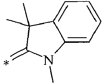
CNA-2 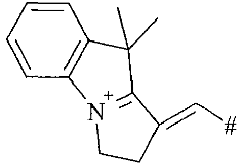
CNC-2 
CNA-3 
CNC-3 
CNA-4 
CNC-4 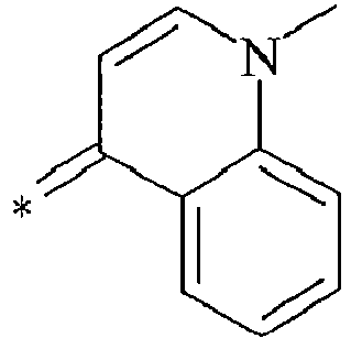
CNA-5 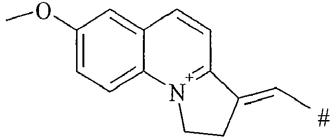
CNC-5 
CNA-6 
CNC-6 
CNA-7 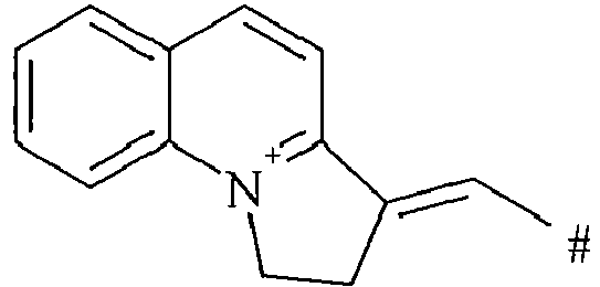
CNC-7 
- Table 16 shows the determined λmax(IR) and the IR/VIS ratio for each infrared dye. The dyes all have chloride as one or more anions to compensate the charge of the dye cation.
Table 16 Dye N° NucA ChB NucC λmax(IR) ≥ IR/VIS ≥ 1100 nm 1125 nm 1140 nm 1150 nm 3.5 7.0 1 CNA-1 CB-1 CNC-1 No No No No Yes Yes 2 CNA-1 CB-3 CNC-1 Yes Yes No No No No 3 CNA-1 CB-5 CNC-1 No No No No Yes Yes 4 CNA-1 CB-6 CNC-1 No No No No Yes Yes 5 CNA-1 CB-7 CNC-1 No No No No Yes Yes 6 CNA-1 CB-10 CNC-1 No No No No Yes Yes 7 CNA-1 CB-11 CNC-1 No No No No Yes Yes 8 CNA-1 CB-12 CNC-1 No No No No Yes Yes 9 CNA-1 CB-14 CNC-1 No No No No Yes Yes 10 CNA-1 CB-18 CNC-1 No No No No No No 11 CNA-2 CB-1 CNC-2 No No No No Yes Yes 12 CNA-2 CB-3 CNC-2 Yes Yes Yes Yes No No 13 CNA-2 CB-26 CNC-2 Yes Yes Yes No No No 14 CNA-3 CB-19 CNC-3 No No No No Yes Yes 15 CNA-4 CB-19 CNC-4 No No No No Yes Yes 16 CNA-4 CB-23 CNC-4 No No No No Yes Yes 17 CNA-5 CB-19 CNC-5 No No No No Yes Yes 18 CNA-6 CB-19 CNC-6 No No No No Yes Yes 19 CNA-7 CB-19 CNC-7 No No No No Yes Yes 20 NA-1 CB-19 NC-1 No No No No Yes Yes 21 NA-2 CB-19 NC-2 No No No No Yes Yes 22 NA-2 CB-25 NC-2 No No No No Yes Yes 23 NA-1 CB-1 NC-1 Yes Yes Yes Yes Yes No 24 NA-1 CB-2 NC-1 Yes Yes Yes Yes Yes No 25 NA-1 CB-4 NC-1 Yes No No No Yes Yes 26 NA-1 CB-5 NC-1 Yes Yes Yes No Yes Yes 27 NA-1 CB-6 NC-1 Yes Yes Yes Yes Yes Yes 28 NA-1 CB-7 NC-1 Yes Yes No No Yes Yes 29 NA-1 CB-8 NC-1 Yes Yes Yes Yes Yes No 30 NA-1 CB-9 NC-1 Yes Yes No No Yes No 31 NA-1 CB-10 NC-1 Yes Yes No No Yes No 32 NA-1 CB-11 NC-1 Yes Yes Yes Yes Yes Yes 33 NA-1 CB-12 NC-1 Yes Yes Yes Yes Yes Yes 34 NA-1 CB-13 NC-1 Yes Yes Yes Yes Yes Yes 35 NA-1 CB-14 NC-1 Yes Yes Yes Yes Yes No 36 NA-1 CB-15 NC-1 Yes Yes Yes Yes Yes No 37 NA-1 CB-16 NC-1 Yes Yes Yes Yes Yes Yes 38 NA-1 CB-17 NC-1 Yes Yes Yes Yes Yes Yes 39 NA-1 CB-17 NC-1 Yes Yes Yes Yes Yes Yes 40 NA-1 CB-18 NC-1 Yes Yes Yes Yes Yes Yes 41 NA-3 CB-19 NC-3 Yes No No No Yes Yes 42 NA-4 CB-19 NC-4 Yes No No No Yes Yes 43 NA-5 CB-19 NC-5 Yes Yes No No Yes Yes 44 NA-5 CB-19 NC-5 Yes No No No Yes Yes 45 NA-5 CB-23 NC-5 Yes Yes No No Yes Yes 46 NA-6 CB-19 NC-6 Yes Yes Yes Yes Yes Yes 47 NA-7 CB-19 NC-7 Yes Yes Yes Yes Yes Yes 48 NA-8 CB-19 NC-8 Yes Yes Yes Yes Yes Yes 49 NA-9 CB-19 NC-9 Yes Yes Yes Yes Yes Yes 50 NA-12 CB-19 NC-12 Yes No No No Yes Yes 51 NA-13 CB-19 NC-13 Yes Yes No No Yes Yes 52 NA-15 CB-19 NC-15 Yes No No No Yes Yes 53 NA-16 CB-19 NC-16 Yes No No No Yes Yes 54 NA-17 CB-19 NC-17 Yes Yes Yes Yes Yes Yes 55 NA-18 CB-19 NC-18 Yes Yes No No Yes Yes 56 NA-19 CB-19 NC-19 Yes Yes Yes No Yes Yes 57 NA-20 CB-19 NC-20 Yes Yes Yes No Yes Yes 58 NA-20 CB-25 NC-20 Yes Yes Yes No Yes Yes 59 NA-21 CB-19 NC-21 Yes Yes Yes Yes Yes Yes 60 NA-22 CB-19 NC-22 Yes Yes No No Yes Yes 61 NA-22 CB-23 NC-22 Yes Yes No No Yes Yes 62 NA-22 CB-24 NC-22 Yes Yes No No Yes Yes 63 NA-24 CB-11 NC-24 Yes Yes No No Yes Yes 64 NA-24 CB-3 NC-24 Yes Yes Yes Yes Yes No - From Table 16, it should be clear that the combination of the nucleus groups A and C and the chain groups B of the newly developed infrared dyes have an absorption maximum above 1100 nm, while maintaining low background discoloration (high IR/VIS ratio).
Claims (15)
- A method for preparing a color laser marked article using three infrared lasers L-1, L-2 and L-3 having respectively a laser emission wavelength of λ(L-1), λ(L-2) and λ(L-3) and comprising the steps of:- laser marking with the infrared laser L-1 a first color laser markable layer including an infrared dye IR-1 having an absorption maximum in the infrared region λmax(IR-1);- laser marking with the infrared laser L-2 a second color laser markable layer including an infrared dye IR-2 having an absorption maximum in the infrared region λmax(IR-2);- laser marking with the infrared laser L-3 a third color laser markable layer including an infrared dye IR-3 having an absorption maximum in the infrared region λmax(IR-3); and- at least partially exposing the color laser markable article to light having a wavelength between 520 nm and 700 nm,
wherein,
the laser emission wavelengths satisfy the condition of:
the infrared red dye absorption maxima satisfy the condition of:
the light emitted by the infrared laser L-1 passes, in order, through the third and second color laser markable layer before exposing the first color laser markable layer. - The method according to claim 1, wherein the light has a wavelength between 550 nm and 600 nm.
- The method according to claim 1 or 2, wherein 800 nm < λmax(IR-3) < 1000 nm.
- The method according to any one of claims 1 to 3, wherein λmax(IR-1) > 1100 nm.
- The method according to any one of claims 1 to 4, wherein the laser emission wavelengths λ(L-1), λ(L-2) and λ(L-3) differ by no more than 30 nm from the infrared red dye absorption maxima λmax(IR-1), λmax(IR-2) and respectively λmax(IR-3).
- The method according to any one of claims 1 to 5, wherein the at least partial exposure is performed using a laser or a LED.
- The method according to any one of claims 1 to 6, wherein the at least partial exposure is performed according to an image.
- The method according to any one of claims 1 to 6, wherein the at least partial exposure is an overall exposure.
- The method according to any one of claims 1 to 8, wherein the color laser markable article is laser marked through a transparent biaxially stretched polyethylene terephthalate foil.
- A color laser marked article containing, in order, at least:a) a core support;b) a first color laser markable layer including an infrared dye IR-1 having an absorption maximum in the infrared region λmax(IR-1);c) a second color laser markable layer including an infrared dye IR-2 having an absorption maximum in the infrared region λmax(IR-2); andd) a third color laser markable layer including an infrared dye IR-3 having an absorption maximum in the infrared region λmax(IR-3);
wherein the infrared dye absorption maxima satisfy the condition of:
and
wherein the absorption of the infrared dye IR-3 at λmax(IR-3) differs by at least 10 % in two area's on the same side of the core support having the same optical density when measured by a spectrophotometer equipped with a visual filter. - The color laser marked article according to claim 10, wherein the condition of 800 nm < λmax(IR-3) < 1000 nm is fulfilled.
- The color laser marked article according to claim 10 or 11, wherein the absorption of the infrared dye IR-1 at λmax(IR-1) differs by no more than 5% in the same two area's on the same side of the core support.
- The color laser marked article according to claim 12, containing an infrared dye IR-1 having a chemical structure A-B-C consisting of a dye cation and an anion to compensate the charge of the dye cation, wherein the nucleus group A of the dye cation is selected from NucA-1 to NucA-3:


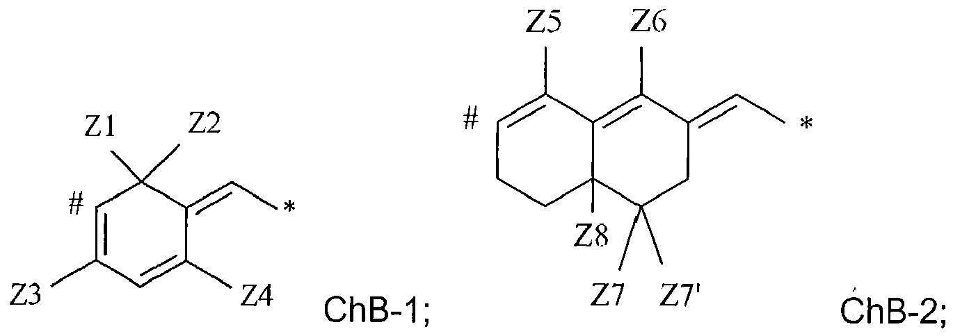
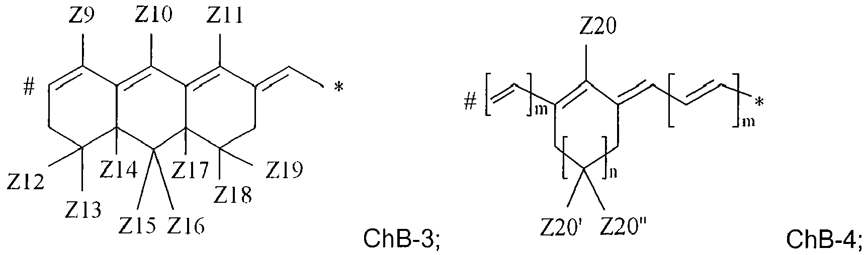


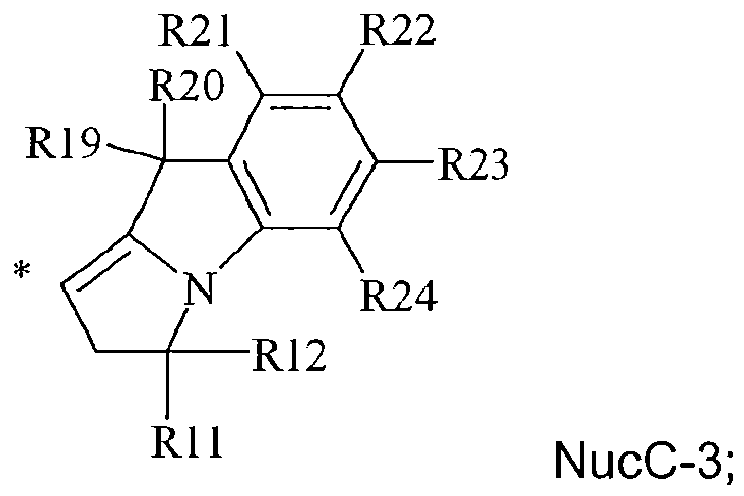
with * indicating the point of attachment between groups B and C; and wherein,
R1 and R5 each independently represent an alkyl group having 1 to 10 carbon atoms;
R3 and R7 each independently represent hydrogen, an alkoxy group having 1 to 10 carbon atoms; a thioalkyl group having 1 to 10 carbon atoms; a cyanide group; an ester group having 2 to 6 carbon atoms; an amide group having 3 to 6 carbon atoms; or a halogen;
R2, R4, R6 and R8 represent hydrogen; or
R2 and R3 may represent the necessary atoms to form a five- or six-membered ring including an oxygen or nitrogen atom directly attached to the carbon atom carrying the R3 group;
R4 and R3 may represent the necessary atoms to form a five- or six-membered ring including an oxygen or nitrogen atom directly attached to the carbon atom carrying the R3 group;
R6 and R7 may represent the necessary atoms to form a five- or six-membered ring including an oxygen or nitrogen atom directly attached to the carbon atom carrying the R7 group;
R8 and R7 may represent the necessary atoms to form a five- or six-membered ring including an oxygen or nitrogen atom directly attached to the carbon atom carrying the R7 group;
R9 to R12 each independently represent hydrogen or an alkyl group having 1 to 8 carbon atoms, or R9 and R10 and/or R11 and R12 may represent the necessary atoms to form an alicyclic five- or six-membered ring;
R13, R14, R19, R20 each independently represent an alkyl group having 1 to 8 carbon atoms;
R15 to R18 each independently represent hydrogen or one of R15 and R16,
R16 and R17 or R17 and R18 may represent the necessary atoms to form a benzene ring;
R21 to R24 each independently represent hydrogen or one of R21 and R22,
R22 and R23 or R23 and R24 may represent the necessary atoms to form a benzene ring;
Z1 and Z2 each independently represent an alkyl group having 1 to 6 carbon atoms, a cyanide group, an ester group having 2 to 6 carbon atoms, an amide group having 3 to 6 carbon atoms, an alicyclic group having 5 to 14 carbon atoms, a heterocyclic group having 2 to 14 carbon atoms, an aryl group having 6 to 14 carbon atoms or a heteroaryl group having 2 to 14 carbon atoms; or Z1 and Z2 may represent the necessary atoms to form an alicyclic group having 5 to 14 carbon atoms or a heterocyclic group having 4 to 14 carbon atoms;
Z3 to Z6 each independently represent hydrogen or halogen;
Z7 and Z7' each independently represent hydrogen, an alkyl group having 1 to 6 carbon atoms, a cyanide group, an ester group having 2 to 6 carbon atoms,
an amide group having 3 to 6 carbon atoms, an alicyclic group having 5 to 14 carbon atoms, a heterocyclic group having 2 to 14 carbon atoms, an aryl group having 6 to 14 carbon atoms or a heteroaryl group having 4 to 14 carbon atoms, or Z7 and Z7' may represent the necessary atoms to form an alicyclic group having 5 to 14 carbon atoms or a heterocyclic group having 4 to 14 carbon atoms;
Z8 represents hydrogen or if at least one of Z7 and Z7' represents hydrogen Z8 may represent an alkyl group having 1 to 6 carbon atoms, a cyanide group,
an ester group having 2 to 6 carbon atoms, an amide group having 1 to 6 carbon atoms or an aryl group having 6 to 14 carbon atoms;
Z9, Z10 and Z11 each independently represent hydrogen or halogen;
Z12 to Z19 each independently represent hydrogen, an alkyl group having 1 to 6 carbon atoms, an aryl group having 6 to 14 carbon atoms, or a heteroaryl group having 2 to 14 carbon atoms, a cyanide group, an ester group having 2 to 6 carbon atoms, an amide group having 3 to 6 carbon atoms or,
one or more of Z12 and Z13, Z15 and Z16 and Z18 and Z19 may represent the necessary atoms to form an alicyclic group having 5 to 14 carbon atoms or a heterocyclic group having 4 to 14 carbon atoms;
Z20 represents hydrogen, a halogen, a thioalkyl group having 1 to 8 carbon atoms, a thioaryl group having 5 to 14 carbon atoms, a thioheteroaryl group having 3 to 14 carbon atoms, an aryl group having 6 to 14 carbon atoms, a diarylamino group, an alkylsulfonyl group having 1 to 8 carbon atoms , an arylsulfonyl group having 6 to 14 carbon atoms or a heteroarylsulfonyl group having 2 to 14 carbon atoms;
the integers m and n independently have a value of 0 or 1;
Z20' and Z20" each independently represent hydrogen, an alkyl group having 1 to 8 carbon atoms, a cyanide group, an ester group having 2 to 8 carbon atoms, an amide group having 3 to 8 carbon atoms or an aryl group having 6 to 14 carbon atoms or Z20' and Z20" may represent the necessary atoms to form an alicyclic group having 5 to 14 carbon atoms or a heterocyclic group having 4 to 14 carbon atoms;
Z21 and Z22 each independently represent hydrogen, halogen, a thioalkyl group having 1 to 8 carbon atoms or a thioaryl group having 5 to 14 carbon atoms;
X represents nitrogen, a -CH-group or if both Z21 and Z22 represent hydrogen then X may represent a -CR-group with R representing an aryl group having 6 to 14 carbon atoms;
Z23 and Z24 each independently represent an alkyl group having 1 to 8 carbon atoms, an aryl group having 6 to 14 carbon atoms or Z23 and Z24 may represent the necessary atoms to form a five- or six-membered ring;
Z25 represents hydrogen or an aryl group;
with the proviso that when the chain group ChB-4 with the integer m = 0 is combined simultaneously with NucA-1 and NucC-1 that R3 and R6 do not represent hydrogen. - The color laser marked article according to any one of claims 10 to 13, wherein the color laser marked article is a security document selected from the group consisting of a passport, a personal identification card and a product identification document.
- Use of light having a wavelength between 520 nm and 700 nm to impede the modification by color laser marking of a color laser marked article containing, in order, at least:a) a core support;b) a first color laser markable layer including an infrared dye IR-1 having an absorption maximum in the infrared region λmax(IR-1);c) a second color laser markable layer including an infrared dye IR-2 having an absorption maximum in the infrared region λmax(IR-2); andd) a third color laser markable layer including an infrared dye IR-3 having an absorption maximum in the infrared region λmax(IR-3);wherein the infrared dye absorption maxima satisfy the condition of:
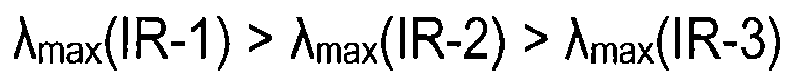
Priority Applications (7)
| Application Number | Priority Date | Filing Date | Title |
|---|---|---|---|
| PL12188143T PL2719540T3 (en) | 2012-10-11 | 2012-10-11 | Color laser marking |
| EP12188143.7A EP2719540B1 (en) | 2012-10-11 | 2012-10-11 | Color laser marking |
| ES12188143.7T ES2547912T3 (en) | 2012-10-11 | 2012-10-11 | Color laser marking |
| IN2651DEN2015 IN2015DN02651A (en) | 2012-10-11 | 2013-10-10 | |
| PCT/EP2013/071170 WO2014057039A1 (en) | 2012-10-11 | 2013-10-10 | Color laser marking |
| US14/433,085 US9604490B2 (en) | 2012-10-11 | 2013-10-10 | Color laser marking |
| CN201380053037.4A CN104703808B (en) | 2012-10-11 | 2013-10-10 | Color laser is marked |
Applications Claiming Priority (1)
| Application Number | Priority Date | Filing Date | Title |
|---|---|---|---|
| EP12188143.7A EP2719540B1 (en) | 2012-10-11 | 2012-10-11 | Color laser marking |
Publications (2)
| Publication Number | Publication Date |
|---|---|
| EP2719540A1 true EP2719540A1 (en) | 2014-04-16 |
| EP2719540B1 EP2719540B1 (en) | 2015-09-09 |
Family
ID=47022543
Family Applications (1)
| Application Number | Title | Priority Date | Filing Date |
|---|---|---|---|
| EP12188143.7A Not-in-force EP2719540B1 (en) | 2012-10-11 | 2012-10-11 | Color laser marking |
Country Status (7)
| Country | Link |
|---|---|
| US (1) | US9604490B2 (en) |
| EP (1) | EP2719540B1 (en) |
| CN (1) | CN104703808B (en) |
| ES (1) | ES2547912T3 (en) |
| IN (1) | IN2015DN02651A (en) |
| PL (1) | PL2719540T3 (en) |
| WO (1) | WO2014057039A1 (en) |
Cited By (28)
| Publication number | Priority date | Publication date | Assignee | Title |
|---|---|---|---|---|
| EP2955029A1 (en) | 2014-06-13 | 2015-12-16 | Agfa-Gevaert | Laser markable materials and documents |
| EP3037274A1 (en) | 2014-12-22 | 2016-06-29 | Agfa-Gevaert | Laser markable security articles and documents |
| WO2016184881A1 (en) | 2015-05-19 | 2016-11-24 | Agfa-Gevaert | Laser markable compositions, articles and documents |
| WO2016184504A1 (en) | 2015-05-19 | 2016-11-24 | Agfa-Gevaert | Laser markable compositions, materials and documents |
| WO2016184741A1 (en) | 2015-05-19 | 2016-11-24 | Agfa-Gevaert | Laser markable compositions, articles and documents |
| WO2016184833A1 (en) | 2015-05-19 | 2016-11-24 | Agfa-Gevaert | Laser markable compositions, articles and documents |
| EP3173249A1 (en) | 2015-11-30 | 2017-05-31 | Agfa-Gevaert | Laser markable compositions and methods to manufacture a packaging therewith |
| EP3219503A1 (en) | 2016-03-16 | 2017-09-20 | Agfa-Gevaert | Process for manufacturing a laser markable packaging |
| EP3252680A1 (en) | 2016-05-31 | 2017-12-06 | Agfa Graphics NV | Authentication method of a two dimensional bar code |
| EP3306532A1 (en) | 2016-10-05 | 2018-04-11 | Agfa-Gevaert | A laser markable rfid tag |
| EP3327088A1 (en) * | 2016-11-28 | 2018-05-30 | Agfa-Gevaert Nv | A multicolour laser marking method |
| EP3354477A1 (en) * | 2017-01-25 | 2018-08-01 | Anheuser-Busch Inbev Sa/Nv | Printing process for a beverage container |
| US10150316B2 (en) | 2015-05-19 | 2018-12-11 | Agfa-Gevaert | Laser markable materials and documents |
| EP3415498A1 (en) | 2017-06-12 | 2018-12-19 | Agfa Nv | A developing agent precursor for laser markable compositions |
| WO2019007833A1 (en) | 2017-07-03 | 2019-01-10 | Agfa Nv | Near infrared (nir) laser markable compositions |
| EP3470134A1 (en) | 2017-10-13 | 2019-04-17 | Agfa Nv | A composition comprising solvent and heat resistant capsules |
| EP3470135A1 (en) | 2017-10-13 | 2019-04-17 | Agfa Nv | A composition comprising solvent and heat resistant capsules |
| EP3505359A1 (en) * | 2017-12-27 | 2019-07-03 | Gemalto Sa | Color laser marking of security document and a method for producing such security document |
| WO2020041743A1 (en) * | 2018-08-23 | 2020-02-27 | The United States Of America, As Represented By The Secretary, Department Of Health And Human Services | Water soluble novel cyanine fluorophore with tunable properties between near ir and swir region for in vivo imaging |
| EP3626472A1 (en) | 2018-09-24 | 2020-03-25 | Agfa Nv | Laser markable compositions |
| EP3626471A1 (en) | 2018-09-24 | 2020-03-25 | Agfa Nv | Laser markable compositions |
| EP3805004A1 (en) | 2019-10-11 | 2021-04-14 | Agfa Nv | Laser markable articles |
| EP3805003A1 (en) | 2019-10-11 | 2021-04-14 | Agfa Nv | Laser markable articles |
| EP3805002A1 (en) | 2019-10-11 | 2021-04-14 | Agfa Nv | Laser markable articles |
| EP3838610A1 (en) | 2019-12-17 | 2021-06-23 | Agfa Nv | Laser markable articles |
| EP3838609A1 (en) | 2019-12-17 | 2021-06-23 | Agfa Nv | Laser markable articles |
| EP3909781A1 (en) | 2020-05-12 | 2021-11-17 | Agfa-Gevaert Nv | Laser markable articles |
| EP3928996A1 (en) * | 2020-06-22 | 2021-12-29 | Agfa Nv | Marking of articles |
Families Citing this family (6)
| Publication number | Priority date | Publication date | Assignee | Title |
|---|---|---|---|---|
| EP2722367B1 (en) * | 2012-10-11 | 2018-03-28 | Agfa-Gevaert | Infrared dyes for laser marking |
| EP3326829B1 (en) * | 2015-07-21 | 2020-11-18 | Dai Nippon Printing Co., Ltd. | Laminated body provided with laser color development layer |
| WO2019002118A1 (en) * | 2017-06-28 | 2019-01-03 | Covestro Deutschland Ag | Improved method for the partial colouring of plastic parts |
| CN108484509B (en) * | 2018-05-18 | 2019-08-06 | 河南大学 | One kind has Boc amino barbiturates-cyclohexadiene spiro-compound and its synthetic method |
| CN112759946A (en) * | 2020-12-31 | 2021-05-07 | 上海戎科特种装备有限公司 | 1064nm laser absorption dye, preparation method thereof and optical-infrared-laser compatible stealth coating |
| CN113070579B (en) * | 2021-04-01 | 2022-05-06 | 派瑞格医疗器械(常州)有限公司 | Method for preventing laser marking fonts on surgical navigation positioning instrument from falling off and rusting |
Citations (22)
| Publication number | Priority date | Publication date | Assignee | Title |
|---|---|---|---|---|
| US3649336A (en) | 1967-09-28 | 1972-03-14 | Agfa Gevaert Nv | Plural coated sheet material |
| GB1441591A (en) | 1972-07-17 | 1976-07-07 | Agfa Gevaert | Process for adhering hydrophilic layers to dimensionally stable polyester film support |
| EP0174054A2 (en) | 1984-09-04 | 1986-03-12 | Polaroid Corporation | Heat-sensitive element for use in a thermal imaging method |
| US4663518A (en) | 1984-09-04 | 1987-05-05 | Polaroid Corporation | Optical storage identification card and read/write system |
| US4720449A (en) | 1985-06-03 | 1988-01-19 | Polaroid Corporation | Thermal imaging method |
| US5219703A (en) | 1992-02-10 | 1993-06-15 | Eastman Kodak Company | Laser-induced thermal dye transfer with bleachable near-infrared absorbing sensitizers |
| EP0605149A2 (en) | 1992-12-17 | 1994-07-06 | Nippon Paper Industries Co., Ltd. | Recording sheet |
| US6100009A (en) | 1997-10-15 | 2000-08-08 | Fuji Photo Film Co., Ltd. | Image recording medium, image recording method and heat coloring polymer compound |
| EP1093015A1 (en) * | 1999-10-13 | 2001-04-18 | Agfa-Gevaert N.V. | IR-photographic sensitizing dyes |
| EP1391315A2 (en) * | 2002-08-19 | 2004-02-25 | Sony Corporation | Reversible multicolor recording medium, and recording method using the same |
| EP1452334A2 (en) | 2003-02-28 | 2004-09-01 | Ricoh Company, Ltd. | Thermosensitive recording material |
| US20060147833A1 (en) * | 2003-01-24 | 2006-07-06 | Kasperchik Vladek P | Color forming compositions with improved marking sensitivity and image contrast and associated methods |
| US7158145B1 (en) | 1999-11-18 | 2007-01-02 | Orga Systems Gmbh | Method for applying colored information on an object |
| US20080238086A1 (en) | 2007-03-27 | 2008-10-02 | Ingrid Geuens | Security document with a transparent pattern and a process for producing a security document with a transparent pattern |
| WO2009063058A1 (en) | 2007-11-15 | 2009-05-22 | Agfa-Gevaert Nv | Biaxially oriented polyester lamella for security laminates |
| WO2009140083A2 (en) | 2008-05-15 | 2009-11-19 | 3M Innovative Properties Company | Generation of color images |
| EP2181858A1 (en) | 2008-11-04 | 2010-05-05 | Agfa-Gevaert N.V. | Security document and methods of producing it |
| EP2374602A1 (en) | 2010-04-08 | 2011-10-12 | Agfa-Gevaert | PET-C based security laminates and documents |
| EP2463109A1 (en) | 2010-12-07 | 2012-06-13 | Agfa-Gevaert | Colour laser marking methods of security documents |
| EP2463110A1 (en) | 2010-12-07 | 2012-06-13 | Agfa-Gevaert | Security document precursor |
| EP2463096A1 (en) * | 2010-12-07 | 2012-06-13 | Agfa-Gevaert | Security documents and colour laser marking methods for securing them |
| WO2012076493A1 (en) | 2010-12-07 | 2012-06-14 | Agfa-Gevaert | Colour laser marking of articles and security documents precursors |
Family Cites Families (29)
| Publication number | Priority date | Publication date | Assignee | Title |
|---|---|---|---|---|
| US3250776A (en) * | 1963-04-05 | 1966-05-10 | Minnesota Mining & Mfg | Haloalkyl spiro barbiturates |
| US4049698A (en) * | 1976-08-05 | 1977-09-20 | Eastman Kodak Company | Process for producing methylene malonic esters |
| US4707425A (en) * | 1983-11-18 | 1987-11-17 | Mitsui Toatsu Chemicals, Incorporated | Optical recording method and media therefor |
| US4772541A (en) * | 1985-11-20 | 1988-09-20 | The Mead Corporation | Photohardenable compositions containing a dye borate complex and photosensitive materials employing the same |
| JP2515162B2 (en) * | 1990-02-23 | 1996-07-10 | 富士写真フイルム株式会社 | Methine compound |
| JP3244288B2 (en) * | 1990-07-23 | 2002-01-07 | 昭和電工株式会社 | Near infrared decolorable recording material |
| US5409797A (en) * | 1991-03-04 | 1995-04-25 | Fuji Photo Film Co., Ltd. | Heat-sensitive recording material for laser recording |
| JP2802693B2 (en) * | 1991-08-14 | 1998-09-24 | 富士写真フイルム株式会社 | Silver halide emulsion |
| JP2779718B2 (en) * | 1991-09-11 | 1998-07-23 | 富士写真フイルム株式会社 | Silver halide photographic material |
| US5502702A (en) * | 1993-08-09 | 1996-03-26 | Yamaha Corporation | Optical disc recording device using basic recording information and projection time control |
| DE4331162A1 (en) * | 1993-09-14 | 1995-03-16 | Bayer Ag | Process for the preparation of cyanine dyes |
| JPH07209858A (en) * | 1994-01-19 | 1995-08-11 | Konica Corp | Photosensitive composition and photosensitive planographic printing plate |
| US5783377A (en) * | 1996-09-04 | 1998-07-21 | Eastman Kodak Company | Infrared absorber dyes |
| DE19857315A1 (en) * | 1997-12-12 | 1999-08-05 | Ricoh Kk | An optical information storage material and display recording method using the same |
| JP4179824B2 (en) * | 2002-08-12 | 2008-11-12 | 富士フイルム株式会社 | Polymerizable composition and planographic printing plate precursor using the same |
| JP2004155010A (en) | 2002-11-06 | 2004-06-03 | Sony Corp | Reversible multicolor recording medium and recording method using the same |
| JP2004246035A (en) * | 2003-02-13 | 2004-09-02 | Fuji Photo Film Co Ltd | Precursor for planographic printing plate |
| JP2005066936A (en) * | 2003-08-21 | 2005-03-17 | Sony Corp | Reversible multi-color recording medium and recording method using this medium |
| WO2005068208A1 (en) * | 2004-01-13 | 2005-07-28 | Nippon Paper Industries Co., Ltd. | Laser recording type heat-sensitive recording medium |
| US20090263612A1 (en) * | 2008-04-18 | 2009-10-22 | Nbc Universal, Inc. | System and Method for Photobleaching of Optical Media |
| JP5515546B2 (en) * | 2008-09-17 | 2014-06-11 | 株式会社リコー | Image erasing method of thermoreversible recording medium |
| ES2400585T3 (en) * | 2008-10-02 | 2013-04-10 | Basf Se | Compositions of color changing, multicolored, photoactive, and UV dosimeters |
| EP2535201B1 (en) * | 2011-06-17 | 2014-10-15 | Agfa-Gevaert | Colour laser marking of articles and security documents |
| EP2567825B1 (en) * | 2011-09-12 | 2014-04-02 | Agfa-Gevaert | Colour laser marking methods of security document precursors |
| EP2639074B1 (en) * | 2012-03-16 | 2015-03-04 | Agfa-Gevaert | Colour laser markable laminates and documents |
| US20130335944A1 (en) * | 2012-06-13 | 2013-12-19 | Robert D. Battis | Cool tube (tm) led lighting |
| EP2722367B1 (en) * | 2012-10-11 | 2018-03-28 | Agfa-Gevaert | Infrared dyes for laser marking |
| EP2719541B1 (en) * | 2012-10-11 | 2015-05-27 | Agfa-Gevaert | Colour laser marking |
| US10245866B2 (en) * | 2012-11-12 | 2019-04-02 | Agfa-Gevaert | Colour imaging of security document precursors |
-
2012
- 2012-10-11 PL PL12188143T patent/PL2719540T3/en unknown
- 2012-10-11 ES ES12188143.7T patent/ES2547912T3/en active Active
- 2012-10-11 EP EP12188143.7A patent/EP2719540B1/en not_active Not-in-force
-
2013
- 2013-10-10 IN IN2651DEN2015 patent/IN2015DN02651A/en unknown
- 2013-10-10 US US14/433,085 patent/US9604490B2/en active Active
- 2013-10-10 CN CN201380053037.4A patent/CN104703808B/en not_active Expired - Fee Related
- 2013-10-10 WO PCT/EP2013/071170 patent/WO2014057039A1/en active Application Filing
Patent Citations (22)
| Publication number | Priority date | Publication date | Assignee | Title |
|---|---|---|---|---|
| US3649336A (en) | 1967-09-28 | 1972-03-14 | Agfa Gevaert Nv | Plural coated sheet material |
| GB1441591A (en) | 1972-07-17 | 1976-07-07 | Agfa Gevaert | Process for adhering hydrophilic layers to dimensionally stable polyester film support |
| EP0174054A2 (en) | 1984-09-04 | 1986-03-12 | Polaroid Corporation | Heat-sensitive element for use in a thermal imaging method |
| US4663518A (en) | 1984-09-04 | 1987-05-05 | Polaroid Corporation | Optical storage identification card and read/write system |
| US4720449A (en) | 1985-06-03 | 1988-01-19 | Polaroid Corporation | Thermal imaging method |
| US5219703A (en) | 1992-02-10 | 1993-06-15 | Eastman Kodak Company | Laser-induced thermal dye transfer with bleachable near-infrared absorbing sensitizers |
| EP0605149A2 (en) | 1992-12-17 | 1994-07-06 | Nippon Paper Industries Co., Ltd. | Recording sheet |
| US6100009A (en) | 1997-10-15 | 2000-08-08 | Fuji Photo Film Co., Ltd. | Image recording medium, image recording method and heat coloring polymer compound |
| EP1093015A1 (en) * | 1999-10-13 | 2001-04-18 | Agfa-Gevaert N.V. | IR-photographic sensitizing dyes |
| US7158145B1 (en) | 1999-11-18 | 2007-01-02 | Orga Systems Gmbh | Method for applying colored information on an object |
| EP1391315A2 (en) * | 2002-08-19 | 2004-02-25 | Sony Corporation | Reversible multicolor recording medium, and recording method using the same |
| US20060147833A1 (en) * | 2003-01-24 | 2006-07-06 | Kasperchik Vladek P | Color forming compositions with improved marking sensitivity and image contrast and associated methods |
| EP1452334A2 (en) | 2003-02-28 | 2004-09-01 | Ricoh Company, Ltd. | Thermosensitive recording material |
| US20080238086A1 (en) | 2007-03-27 | 2008-10-02 | Ingrid Geuens | Security document with a transparent pattern and a process for producing a security document with a transparent pattern |
| WO2009063058A1 (en) | 2007-11-15 | 2009-05-22 | Agfa-Gevaert Nv | Biaxially oriented polyester lamella for security laminates |
| WO2009140083A2 (en) | 2008-05-15 | 2009-11-19 | 3M Innovative Properties Company | Generation of color images |
| EP2181858A1 (en) | 2008-11-04 | 2010-05-05 | Agfa-Gevaert N.V. | Security document and methods of producing it |
| EP2374602A1 (en) | 2010-04-08 | 2011-10-12 | Agfa-Gevaert | PET-C based security laminates and documents |
| EP2463109A1 (en) | 2010-12-07 | 2012-06-13 | Agfa-Gevaert | Colour laser marking methods of security documents |
| EP2463110A1 (en) | 2010-12-07 | 2012-06-13 | Agfa-Gevaert | Security document precursor |
| EP2463096A1 (en) * | 2010-12-07 | 2012-06-13 | Agfa-Gevaert | Security documents and colour laser marking methods for securing them |
| WO2012076493A1 (en) | 2010-12-07 | 2012-06-14 | Agfa-Gevaert | Colour laser marking of articles and security documents precursors |
Non-Patent Citations (2)
| Title |
|---|
| HALDER SINHA ET AL., EUROPEAN JOURNAL OF MEDICINAL CHEMISTRY, vol. 54, 2012, pages 647 - 659 |
| MANFRED PULST; BERND HOLLBORN, MANFRED WEISSENFELS JOURNAL F. PRAKT. CHEMIE, vol. 321, no. 4, 1979, pages 671 - 674 |
Cited By (56)
| Publication number | Priority date | Publication date | Assignee | Title |
|---|---|---|---|---|
| US10150327B2 (en) | 2014-06-13 | 2018-12-11 | Agfa-Gevaert | Laser markable materials and documents |
| EP2955029A1 (en) | 2014-06-13 | 2015-12-16 | Agfa-Gevaert | Laser markable materials and documents |
| CN107107636B (en) * | 2014-12-22 | 2019-11-05 | 爱克发-格法特公司 | The security article and file of laser marking |
| EP3037274A1 (en) | 2014-12-22 | 2016-06-29 | Agfa-Gevaert | Laser markable security articles and documents |
| WO2016102366A1 (en) * | 2014-12-22 | 2016-06-30 | Agfa-Gevaert | Laser markable security articles and documents |
| CN107107636A (en) * | 2014-12-22 | 2017-08-29 | 爱克发-格法特公司 | The security article and file of laser marking |
| US10265995B2 (en) | 2014-12-22 | 2019-04-23 | Agfa-Gevaert | Laser markable security articles and documents |
| WO2016184833A1 (en) | 2015-05-19 | 2016-11-24 | Agfa-Gevaert | Laser markable compositions, articles and documents |
| WO2016184741A1 (en) | 2015-05-19 | 2016-11-24 | Agfa-Gevaert | Laser markable compositions, articles and documents |
| US10144238B2 (en) | 2015-05-19 | 2018-12-04 | Agfa-Gevaert | Laser markable compositions, articles and documents |
| US10144239B2 (en) | 2015-05-19 | 2018-12-04 | Agfa-Gevaert | Laser markable compositions, articles and documents |
| US10150316B2 (en) | 2015-05-19 | 2018-12-11 | Agfa-Gevaert | Laser markable materials and documents |
| WO2016184504A1 (en) | 2015-05-19 | 2016-11-24 | Agfa-Gevaert | Laser markable compositions, materials and documents |
| US10286708B2 (en) | 2015-05-19 | 2019-05-14 | Agfa-Gevaert | Laser markable compositions, articles and documents |
| US10286707B2 (en) | 2015-05-19 | 2019-05-14 | Agfa-Gevaert | Laser markable compositions, materials and documents |
| WO2016184881A1 (en) | 2015-05-19 | 2016-11-24 | Agfa-Gevaert | Laser markable compositions, articles and documents |
| EP3173249A1 (en) | 2015-11-30 | 2017-05-31 | Agfa-Gevaert | Laser markable compositions and methods to manufacture a packaging therewith |
| WO2017093228A2 (en) | 2015-11-30 | 2017-06-08 | Agfa-Gevaert | Laser markable compositions and methods to manufacture a packaging therewith |
| EP3219503A1 (en) | 2016-03-16 | 2017-09-20 | Agfa-Gevaert | Process for manufacturing a laser markable packaging |
| WO2017157888A1 (en) | 2016-03-16 | 2017-09-21 | Agfa-Gevaert | Process for manufacturing a laser markable packaging |
| WO2017207344A1 (en) | 2016-05-31 | 2017-12-07 | Agfa Graphics Nv | Authentication method of a two dimensional bar code |
| EP3252680A1 (en) | 2016-05-31 | 2017-12-06 | Agfa Graphics NV | Authentication method of a two dimensional bar code |
| WO2018065506A1 (en) | 2016-10-05 | 2018-04-12 | Agfa-Gevaert | A laser markable rfid tag |
| EP3306532A1 (en) | 2016-10-05 | 2018-04-11 | Agfa-Gevaert | A laser markable rfid tag |
| EP3327088A1 (en) * | 2016-11-28 | 2018-05-30 | Agfa-Gevaert Nv | A multicolour laser marking method |
| WO2018096096A1 (en) * | 2016-11-28 | 2018-05-31 | Agfa-Gevaert N.V. | A multicolour laser marking method |
| EP3354477A1 (en) * | 2017-01-25 | 2018-08-01 | Anheuser-Busch Inbev Sa/Nv | Printing process for a beverage container |
| WO2018138232A3 (en) * | 2017-01-25 | 2018-10-04 | Anheuser-Busch Inbev Sa/Nv | Printing process for a beverage container |
| EP3415498A1 (en) | 2017-06-12 | 2018-12-19 | Agfa Nv | A developing agent precursor for laser markable compositions |
| WO2018228857A1 (en) | 2017-06-12 | 2018-12-20 | Agfa Nv | A developing agent precursor for laser markable compositions |
| WO2019007833A1 (en) | 2017-07-03 | 2019-01-10 | Agfa Nv | Near infrared (nir) laser markable compositions |
| EP3470135A1 (en) | 2017-10-13 | 2019-04-17 | Agfa Nv | A composition comprising solvent and heat resistant capsules |
| WO2019072758A1 (en) | 2017-10-13 | 2019-04-18 | Agfa Nv | A composition comprising solvent and heat resistant capsules |
| WO2019072749A1 (en) | 2017-10-13 | 2019-04-18 | Agfa Nv | A composition comprising solvent and heat resistant capsules |
| EP3470134A1 (en) | 2017-10-13 | 2019-04-17 | Agfa Nv | A composition comprising solvent and heat resistant capsules |
| EP3505359A1 (en) * | 2017-12-27 | 2019-07-03 | Gemalto Sa | Color laser marking of security document and a method for producing such security document |
| WO2019129527A1 (en) * | 2017-12-27 | 2019-07-04 | Gemalto Sa | Color laser marking of security document and a method for producing such security document |
| US11084315B2 (en) | 2017-12-27 | 2021-08-10 | Thales Dis France Sa | Color laser marking of security document and a method for producing such security document |
| WO2020041743A1 (en) * | 2018-08-23 | 2020-02-27 | The United States Of America, As Represented By The Secretary, Department Of Health And Human Services | Water soluble novel cyanine fluorophore with tunable properties between near ir and swir region for in vivo imaging |
| US11465993B2 (en) | 2018-08-23 | 2022-10-11 | The United States Of America, As Represented By The Secretary, Department Of Health And Human Services | Water soluble novel cyanine fluorophore with tunable properties between near IR and SWIR region for in vivo imaging |
| EP3626472A1 (en) | 2018-09-24 | 2020-03-25 | Agfa Nv | Laser markable compositions |
| EP3626471A1 (en) | 2018-09-24 | 2020-03-25 | Agfa Nv | Laser markable compositions |
| WO2020064633A1 (en) | 2018-09-24 | 2020-04-02 | Agfa Nv | Laser markable compositions |
| WO2020064427A1 (en) | 2018-09-24 | 2020-04-02 | Agfa Nv | Laser markable compositions |
| EP3805002A1 (en) | 2019-10-11 | 2021-04-14 | Agfa Nv | Laser markable articles |
| WO2021069255A1 (en) | 2019-10-11 | 2021-04-15 | Agfa Nv | Laser markable articles |
| WO2021069257A1 (en) | 2019-10-11 | 2021-04-15 | Agfa Nv | Laser markable articles |
| WO2021069406A1 (en) | 2019-10-11 | 2021-04-15 | Agfa Nv | Laser markable articles |
| EP3805003A1 (en) | 2019-10-11 | 2021-04-14 | Agfa Nv | Laser markable articles |
| EP3805004A1 (en) | 2019-10-11 | 2021-04-14 | Agfa Nv | Laser markable articles |
| EP3838610A1 (en) | 2019-12-17 | 2021-06-23 | Agfa Nv | Laser markable articles |
| EP3838609A1 (en) | 2019-12-17 | 2021-06-23 | Agfa Nv | Laser markable articles |
| WO2021121927A1 (en) | 2019-12-17 | 2021-06-24 | Agfa Nv | Laser markable articles |
| WO2021121919A1 (en) | 2019-12-17 | 2021-06-24 | Agfa Nv | Laser markable articles |
| EP3909781A1 (en) | 2020-05-12 | 2021-11-17 | Agfa-Gevaert Nv | Laser markable articles |
| EP3928996A1 (en) * | 2020-06-22 | 2021-12-29 | Agfa Nv | Marking of articles |
Also Published As
| Publication number | Publication date |
|---|---|
| PL2719540T3 (en) | 2016-03-31 |
| CN104703808B (en) | 2017-06-13 |
| IN2015DN02651A (en) | 2015-09-18 |
| EP2719540B1 (en) | 2015-09-09 |
| CN104703808A (en) | 2015-06-10 |
| US9604490B2 (en) | 2017-03-28 |
| WO2014057039A1 (en) | 2014-04-17 |
| ES2547912T3 (en) | 2015-10-09 |
| US20150251481A1 (en) | 2015-09-10 |
Similar Documents
| Publication | Publication Date | Title |
|---|---|---|
| EP2719540B1 (en) | Color laser marking | |
| EP2722367B1 (en) | Infrared dyes for laser marking | |
| EP2719541B1 (en) | Colour laser marking | |
| US9821586B2 (en) | IR dyes and laser markable articles comprising such IR dyes | |
| US9931878B2 (en) | Colour laser markable laminates and documents | |
| EP3083261B1 (en) | Laser markable laminates and documents | |
| US8921265B2 (en) | Colour laser marking methods of security documents | |
| US20130230704A1 (en) | Colour laser marking of articles and security document precursors | |
| US10245866B2 (en) | Colour imaging of security document precursors | |
| EP2730425B1 (en) | Colour imaging of security document precursors | |
| US9403395B2 (en) | Colour laser markable laminates and documents | |
| US10150327B2 (en) | Laser markable materials and documents | |
| WO2012171728A1 (en) | Colour laser marking of articles and security documents |
Legal Events
| Date | Code | Title | Description |
|---|---|---|---|
| PUAI | Public reference made under article 153(3) epc to a published international application that has entered the european phase |
Free format text: ORIGINAL CODE: 0009012 |
|
| AK | Designated contracting states |
Kind code of ref document: A1 Designated state(s): AL AT BE BG CH CY CZ DE DK EE ES FI FR GB GR HR HU IE IS IT LI LT LU LV MC MK MT NL NO PL PT RO RS SE SI SK SM TR |
|
| AX | Request for extension of the european patent |
Extension state: BA ME |
|
| 17P | Request for examination filed |
Effective date: 20141016 |
|
| RBV | Designated contracting states (corrected) |
Designated state(s): AL AT BE BG CH CY CZ DE DK EE ES FI FR GB GR HR HU IE IS IT LI LT LU LV MC MK MT NL NO PL PT RO RS SE SI SK SM TR |
|
| GRAP | Despatch of communication of intention to grant a patent |
Free format text: ORIGINAL CODE: EPIDOSNIGR1 |
|
| INTG | Intention to grant announced |
Effective date: 20150506 |
|
| GRAS | Grant fee paid |
Free format text: ORIGINAL CODE: EPIDOSNIGR3 |
|
| GRAA | (expected) grant |
Free format text: ORIGINAL CODE: 0009210 |
|
| AK | Designated contracting states |
Kind code of ref document: B1 Designated state(s): AL AT BE BG CH CY CZ DE DK EE ES FI FR GB GR HR HU IE IS IT LI LT LU LV MC MK MT NL NO PL PT RO RS SE SI SK SM TR |
|
| REG | Reference to a national code |
Ref country code: GB Ref legal event code: FG4D |
|
| REG | Reference to a national code |
Ref country code: AT Ref legal event code: REF Ref document number: 747800 Country of ref document: AT Kind code of ref document: T Effective date: 20150915 Ref country code: CH Ref legal event code: EP |
|
| REG | Reference to a national code |
Ref country code: IE Ref legal event code: FG4D |
|
| REG | Reference to a national code |
Ref country code: ES Ref legal event code: FG2A Ref document number: 2547912 Country of ref document: ES Kind code of ref document: T3 Effective date: 20151009 |
|
| REG | Reference to a national code |
Ref country code: DE Ref legal event code: R096 Ref document number: 602012010275 Country of ref document: DE |
|
| REG | Reference to a national code |
Ref country code: NL Ref legal event code: FP |
|
| PG25 | Lapsed in a contracting state [announced via postgrant information from national office to epo] |
Ref country code: FI Free format text: LAPSE BECAUSE OF FAILURE TO SUBMIT A TRANSLATION OF THE DESCRIPTION OR TO PAY THE FEE WITHIN THE PRESCRIBED TIME-LIMIT Effective date: 20150909 Ref country code: GR Free format text: LAPSE BECAUSE OF FAILURE TO SUBMIT A TRANSLATION OF THE DESCRIPTION OR TO PAY THE FEE WITHIN THE PRESCRIBED TIME-LIMIT Effective date: 20151210 Ref country code: NO Free format text: LAPSE BECAUSE OF FAILURE TO SUBMIT A TRANSLATION OF THE DESCRIPTION OR TO PAY THE FEE WITHIN THE PRESCRIBED TIME-LIMIT Effective date: 20151209 Ref country code: LV Free format text: LAPSE BECAUSE OF FAILURE TO SUBMIT A TRANSLATION OF THE DESCRIPTION OR TO PAY THE FEE WITHIN THE PRESCRIBED TIME-LIMIT Effective date: 20150909 Ref country code: LT Free format text: LAPSE BECAUSE OF FAILURE TO SUBMIT A TRANSLATION OF THE DESCRIPTION OR TO PAY THE FEE WITHIN THE PRESCRIBED TIME-LIMIT Effective date: 20150909 |
|
| REG | Reference to a national code |
Ref country code: LT Ref legal event code: MG4D |
|
| REG | Reference to a national code |
Ref country code: AT Ref legal event code: MK05 Ref document number: 747800 Country of ref document: AT Kind code of ref document: T Effective date: 20150909 |
|
| PG25 | Lapsed in a contracting state [announced via postgrant information from national office to epo] |
Ref country code: RS Free format text: LAPSE BECAUSE OF FAILURE TO SUBMIT A TRANSLATION OF THE DESCRIPTION OR TO PAY THE FEE WITHIN THE PRESCRIBED TIME-LIMIT Effective date: 20150909 Ref country code: SE Free format text: LAPSE BECAUSE OF FAILURE TO SUBMIT A TRANSLATION OF THE DESCRIPTION OR TO PAY THE FEE WITHIN THE PRESCRIBED TIME-LIMIT Effective date: 20150909 Ref country code: HR Free format text: LAPSE BECAUSE OF FAILURE TO SUBMIT A TRANSLATION OF THE DESCRIPTION OR TO PAY THE FEE WITHIN THE PRESCRIBED TIME-LIMIT Effective date: 20150909 |
|
| PG25 | Lapsed in a contracting state [announced via postgrant information from national office to epo] |
Ref country code: IS Free format text: LAPSE BECAUSE OF FAILURE TO SUBMIT A TRANSLATION OF THE DESCRIPTION OR TO PAY THE FEE WITHIN THE PRESCRIBED TIME-LIMIT Effective date: 20160109 Ref country code: SK Free format text: LAPSE BECAUSE OF FAILURE TO SUBMIT A TRANSLATION OF THE DESCRIPTION OR TO PAY THE FEE WITHIN THE PRESCRIBED TIME-LIMIT Effective date: 20150909 Ref country code: EE Free format text: LAPSE BECAUSE OF FAILURE TO SUBMIT A TRANSLATION OF THE DESCRIPTION OR TO PAY THE FEE WITHIN THE PRESCRIBED TIME-LIMIT Effective date: 20150909 Ref country code: CZ Free format text: LAPSE BECAUSE OF FAILURE TO SUBMIT A TRANSLATION OF THE DESCRIPTION OR TO PAY THE FEE WITHIN THE PRESCRIBED TIME-LIMIT Effective date: 20150909 |
|
| PG25 | Lapsed in a contracting state [announced via postgrant information from national office to epo] |
Ref country code: AT Free format text: LAPSE BECAUSE OF FAILURE TO SUBMIT A TRANSLATION OF THE DESCRIPTION OR TO PAY THE FEE WITHIN THE PRESCRIBED TIME-LIMIT Effective date: 20150909 Ref country code: RO Free format text: LAPSE BECAUSE OF FAILURE TO SUBMIT A TRANSLATION OF THE DESCRIPTION OR TO PAY THE FEE WITHIN THE PRESCRIBED TIME-LIMIT Effective date: 20150909 Ref country code: PT Free format text: LAPSE BECAUSE OF FAILURE TO SUBMIT A TRANSLATION OF THE DESCRIPTION OR TO PAY THE FEE WITHIN THE PRESCRIBED TIME-LIMIT Effective date: 20160111 |
|
| REG | Reference to a national code |
Ref country code: CH Ref legal event code: PL |
|
| REG | Reference to a national code |
Ref country code: DE Ref legal event code: R097 Ref document number: 602012010275 Country of ref document: DE |
|
| PG25 | Lapsed in a contracting state [announced via postgrant information from national office to epo] |
Ref country code: MC Free format text: LAPSE BECAUSE OF FAILURE TO SUBMIT A TRANSLATION OF THE DESCRIPTION OR TO PAY THE FEE WITHIN THE PRESCRIBED TIME-LIMIT Effective date: 20150909 |
|
| PLBE | No opposition filed within time limit |
Free format text: ORIGINAL CODE: 0009261 |
|
| STAA | Information on the status of an ep patent application or granted ep patent |
Free format text: STATUS: NO OPPOSITION FILED WITHIN TIME LIMIT |
|
| REG | Reference to a national code |
Ref country code: IE Ref legal event code: MM4A Ref country code: FR Ref legal event code: PLFP Year of fee payment: 5 |
|
| PG25 | Lapsed in a contracting state [announced via postgrant information from national office to epo] |
Ref country code: LI Free format text: LAPSE BECAUSE OF NON-PAYMENT OF DUE FEES Effective date: 20151031 Ref country code: CH Free format text: LAPSE BECAUSE OF NON-PAYMENT OF DUE FEES Effective date: 20151031 |
|
| 26N | No opposition filed |
Effective date: 20160610 |
|
| PG25 | Lapsed in a contracting state [announced via postgrant information from national office to epo] |
Ref country code: SI Free format text: LAPSE BECAUSE OF FAILURE TO SUBMIT A TRANSLATION OF THE DESCRIPTION OR TO PAY THE FEE WITHIN THE PRESCRIBED TIME-LIMIT Effective date: 20150909 Ref country code: DK Free format text: LAPSE BECAUSE OF FAILURE TO SUBMIT A TRANSLATION OF THE DESCRIPTION OR TO PAY THE FEE WITHIN THE PRESCRIBED TIME-LIMIT Effective date: 20150909 |
|
| PG25 | Lapsed in a contracting state [announced via postgrant information from national office to epo] |
Ref country code: IE Free format text: LAPSE BECAUSE OF NON-PAYMENT OF DUE FEES Effective date: 20151011 |
|
| PG25 | Lapsed in a contracting state [announced via postgrant information from national office to epo] |
Ref country code: SM Free format text: LAPSE BECAUSE OF FAILURE TO SUBMIT A TRANSLATION OF THE DESCRIPTION OR TO PAY THE FEE WITHIN THE PRESCRIBED TIME-LIMIT Effective date: 20150909 Ref country code: HU Free format text: LAPSE BECAUSE OF FAILURE TO SUBMIT A TRANSLATION OF THE DESCRIPTION OR TO PAY THE FEE WITHIN THE PRESCRIBED TIME-LIMIT; INVALID AB INITIO Effective date: 20121011 Ref country code: BG Free format text: LAPSE BECAUSE OF FAILURE TO SUBMIT A TRANSLATION OF THE DESCRIPTION OR TO PAY THE FEE WITHIN THE PRESCRIBED TIME-LIMIT Effective date: 20150909 |
|
| PG25 | Lapsed in a contracting state [announced via postgrant information from national office to epo] |
Ref country code: CY Free format text: LAPSE BECAUSE OF FAILURE TO SUBMIT A TRANSLATION OF THE DESCRIPTION OR TO PAY THE FEE WITHIN THE PRESCRIBED TIME-LIMIT Effective date: 20150909 |
|
| REG | Reference to a national code |
Ref country code: FR Ref legal event code: PLFP Year of fee payment: 6 |
|
| PG25 | Lapsed in a contracting state [announced via postgrant information from national office to epo] |
Ref country code: MT Free format text: LAPSE BECAUSE OF FAILURE TO SUBMIT A TRANSLATION OF THE DESCRIPTION OR TO PAY THE FEE WITHIN THE PRESCRIBED TIME-LIMIT Effective date: 20150909 |
|
| PG25 | Lapsed in a contracting state [announced via postgrant information from national office to epo] |
Ref country code: LU Free format text: LAPSE BECAUSE OF NON-PAYMENT OF DUE FEES Effective date: 20151011 |
|
| PG25 | Lapsed in a contracting state [announced via postgrant information from national office to epo] |
Ref country code: MK Free format text: LAPSE BECAUSE OF FAILURE TO SUBMIT A TRANSLATION OF THE DESCRIPTION OR TO PAY THE FEE WITHIN THE PRESCRIBED TIME-LIMIT Effective date: 20150909 |
|
| REG | Reference to a national code |
Ref country code: FR Ref legal event code: PLFP Year of fee payment: 7 |
|
| PG25 | Lapsed in a contracting state [announced via postgrant information from national office to epo] |
Ref country code: TR Free format text: LAPSE BECAUSE OF FAILURE TO SUBMIT A TRANSLATION OF THE DESCRIPTION OR TO PAY THE FEE WITHIN THE PRESCRIBED TIME-LIMIT Effective date: 20150909 Ref country code: AL Free format text: LAPSE BECAUSE OF FAILURE TO SUBMIT A TRANSLATION OF THE DESCRIPTION OR TO PAY THE FEE WITHIN THE PRESCRIBED TIME-LIMIT Effective date: 20150909 |
|
| PGFP | Annual fee paid to national office [announced via postgrant information from national office to epo] |
Ref country code: NL Payment date: 20200731 Year of fee payment: 9 |
|
| PGFP | Annual fee paid to national office [announced via postgrant information from national office to epo] |
Ref country code: FR Payment date: 20200731 Year of fee payment: 9 Ref country code: GB Payment date: 20200803 Year of fee payment: 9 |
|
| PGFP | Annual fee paid to national office [announced via postgrant information from national office to epo] |
Ref country code: BE Payment date: 20200731 Year of fee payment: 9 |
|
| PGFP | Annual fee paid to national office [announced via postgrant information from national office to epo] |
Ref country code: DE Payment date: 20200731 Year of fee payment: 9 Ref country code: ES Payment date: 20201117 Year of fee payment: 9 Ref country code: IT Payment date: 20201030 Year of fee payment: 9 |
|
| PGFP | Annual fee paid to national office [announced via postgrant information from national office to epo] |
Ref country code: PL Payment date: 20201005 Year of fee payment: 9 |
|
| REG | Reference to a national code |
Ref country code: DE Ref legal event code: R119 Ref document number: 602012010275 Country of ref document: DE |
|
| REG | Reference to a national code |
Ref country code: NL Ref legal event code: MM Effective date: 20211101 |
|
| REG | Reference to a national code |
Ref country code: BE Ref legal event code: MM Effective date: 20211031 |
|
| GBPC | Gb: european patent ceased through non-payment of renewal fee |
Effective date: 20211011 |
|
| PG25 | Lapsed in a contracting state [announced via postgrant information from national office to epo] |
Ref country code: NL Free format text: LAPSE BECAUSE OF NON-PAYMENT OF DUE FEES Effective date: 20211101 Ref country code: GB Free format text: LAPSE BECAUSE OF NON-PAYMENT OF DUE FEES Effective date: 20211011 Ref country code: DE Free format text: LAPSE BECAUSE OF NON-PAYMENT OF DUE FEES Effective date: 20220503 Ref country code: BE Free format text: LAPSE BECAUSE OF NON-PAYMENT OF DUE FEES Effective date: 20211031 |
|
| PG25 | Lapsed in a contracting state [announced via postgrant information from national office to epo] |
Ref country code: FR Free format text: LAPSE BECAUSE OF NON-PAYMENT OF DUE FEES Effective date: 20211031 |
|
| PG25 | Lapsed in a contracting state [announced via postgrant information from national office to epo] |
Ref country code: IT Free format text: LAPSE BECAUSE OF NON-PAYMENT OF DUE FEES Effective date: 20211011 |
|
| REG | Reference to a national code |
Ref country code: ES Ref legal event code: FD2A Effective date: 20230213 |
|
| PG25 | Lapsed in a contracting state [announced via postgrant information from national office to epo] |
Ref country code: ES Free format text: LAPSE BECAUSE OF NON-PAYMENT OF DUE FEES Effective date: 20211012 |
|
| PG25 | Lapsed in a contracting state [announced via postgrant information from national office to epo] |
Ref country code: PL Free format text: LAPSE BECAUSE OF NON-PAYMENT OF DUE FEES Effective date: 20211011 |