EP2726757B1 - Electrical architecture of a hybrid vehicle, hybrid vehicle and control method - Google Patents
Electrical architecture of a hybrid vehicle, hybrid vehicle and control method Download PDFInfo
- Publication number
- EP2726757B1 EP2726757B1 EP12731076.1A EP12731076A EP2726757B1 EP 2726757 B1 EP2726757 B1 EP 2726757B1 EP 12731076 A EP12731076 A EP 12731076A EP 2726757 B1 EP2726757 B1 EP 2726757B1
- Authority
- EP
- European Patent Office
- Prior art keywords
- battery
- combustion engine
- voltage
- vehicle
- electric
- Prior art date
- Legal status (The legal status is an assumption and is not a legal conclusion. Google has not performed a legal analysis and makes no representation as to the accuracy of the status listed.)
- Active
Links
- 238000000034 method Methods 0.000 title claims description 6
- 230000005540 biological transmission Effects 0.000 claims description 25
- 230000008878 coupling Effects 0.000 claims description 19
- 238000010168 coupling process Methods 0.000 claims description 19
- 238000005859 coupling reaction Methods 0.000 claims description 19
- 238000002485 combustion reaction Methods 0.000 claims description 11
- 230000002441 reversible effect Effects 0.000 claims description 5
- 239000007858 starting material Substances 0.000 claims description 5
- 230000005611 electricity Effects 0.000 claims 1
- 239000007787 solid Substances 0.000 description 7
- 230000008901 benefit Effects 0.000 description 3
- 230000007935 neutral effect Effects 0.000 description 3
- 230000000750 progressive effect Effects 0.000 description 2
- 238000011217 control strategy Methods 0.000 description 1
- 238000013016 damping Methods 0.000 description 1
- 229940082150 encore Drugs 0.000 description 1
- 238000001914 filtration Methods 0.000 description 1
- 230000002035 prolonged effect Effects 0.000 description 1
- 230000008929 regeneration Effects 0.000 description 1
- 238000011069 regeneration method Methods 0.000 description 1
- 238000004804 winding Methods 0.000 description 1
Images


Classifications
-
- B—PERFORMING OPERATIONS; TRANSPORTING
- B60—VEHICLES IN GENERAL
- B60K—ARRANGEMENT OR MOUNTING OF PROPULSION UNITS OR OF TRANSMISSIONS IN VEHICLES; ARRANGEMENT OR MOUNTING OF PLURAL DIVERSE PRIME-MOVERS IN VEHICLES; AUXILIARY DRIVES FOR VEHICLES; INSTRUMENTATION OR DASHBOARDS FOR VEHICLES; ARRANGEMENTS IN CONNECTION WITH COOLING, AIR INTAKE, GAS EXHAUST OR FUEL SUPPLY OF PROPULSION UNITS IN VEHICLES
- B60K6/00—Arrangement or mounting of plural diverse prime-movers for mutual or common propulsion, e.g. hybrid propulsion systems comprising electric motors and internal combustion engines ; Control systems therefor, i.e. systems controlling two or more prime movers, or controlling one of these prime movers and any of the transmission, drive or drive units Informative references: mechanical gearings with secondary electric drive F16H3/72; arrangements for handling mechanical energy structurally associated with the dynamo-electric machine H02K7/00; machines comprising structurally interrelated motor and generator parts H02K51/00; dynamo-electric machines not otherwise provided for in H02K see H02K99/00
- B60K6/20—Arrangement or mounting of plural diverse prime-movers for mutual or common propulsion, e.g. hybrid propulsion systems comprising electric motors and internal combustion engines ; Control systems therefor, i.e. systems controlling two or more prime movers, or controlling one of these prime movers and any of the transmission, drive or drive units Informative references: mechanical gearings with secondary electric drive F16H3/72; arrangements for handling mechanical energy structurally associated with the dynamo-electric machine H02K7/00; machines comprising structurally interrelated motor and generator parts H02K51/00; dynamo-electric machines not otherwise provided for in H02K see H02K99/00 the prime-movers consisting of electric motors and internal combustion engines, e.g. HEVs
- B60K6/22—Arrangement or mounting of plural diverse prime-movers for mutual or common propulsion, e.g. hybrid propulsion systems comprising electric motors and internal combustion engines ; Control systems therefor, i.e. systems controlling two or more prime movers, or controlling one of these prime movers and any of the transmission, drive or drive units Informative references: mechanical gearings with secondary electric drive F16H3/72; arrangements for handling mechanical energy structurally associated with the dynamo-electric machine H02K7/00; machines comprising structurally interrelated motor and generator parts H02K51/00; dynamo-electric machines not otherwise provided for in H02K see H02K99/00 the prime-movers consisting of electric motors and internal combustion engines, e.g. HEVs characterised by apparatus, components or means specially adapted for HEVs
- B60K6/28—Arrangement or mounting of plural diverse prime-movers for mutual or common propulsion, e.g. hybrid propulsion systems comprising electric motors and internal combustion engines ; Control systems therefor, i.e. systems controlling two or more prime movers, or controlling one of these prime movers and any of the transmission, drive or drive units Informative references: mechanical gearings with secondary electric drive F16H3/72; arrangements for handling mechanical energy structurally associated with the dynamo-electric machine H02K7/00; machines comprising structurally interrelated motor and generator parts H02K51/00; dynamo-electric machines not otherwise provided for in H02K see H02K99/00 the prime-movers consisting of electric motors and internal combustion engines, e.g. HEVs characterised by apparatus, components or means specially adapted for HEVs characterised by the electric energy storing means, e.g. batteries or capacitors
-
- B—PERFORMING OPERATIONS; TRANSPORTING
- B60—VEHICLES IN GENERAL
- B60K—ARRANGEMENT OR MOUNTING OF PROPULSION UNITS OR OF TRANSMISSIONS IN VEHICLES; ARRANGEMENT OR MOUNTING OF PLURAL DIVERSE PRIME-MOVERS IN VEHICLES; AUXILIARY DRIVES FOR VEHICLES; INSTRUMENTATION OR DASHBOARDS FOR VEHICLES; ARRANGEMENTS IN CONNECTION WITH COOLING, AIR INTAKE, GAS EXHAUST OR FUEL SUPPLY OF PROPULSION UNITS IN VEHICLES
- B60K6/00—Arrangement or mounting of plural diverse prime-movers for mutual or common propulsion, e.g. hybrid propulsion systems comprising electric motors and internal combustion engines ; Control systems therefor, i.e. systems controlling two or more prime movers, or controlling one of these prime movers and any of the transmission, drive or drive units Informative references: mechanical gearings with secondary electric drive F16H3/72; arrangements for handling mechanical energy structurally associated with the dynamo-electric machine H02K7/00; machines comprising structurally interrelated motor and generator parts H02K51/00; dynamo-electric machines not otherwise provided for in H02K see H02K99/00
- B60K6/20—Arrangement or mounting of plural diverse prime-movers for mutual or common propulsion, e.g. hybrid propulsion systems comprising electric motors and internal combustion engines ; Control systems therefor, i.e. systems controlling two or more prime movers, or controlling one of these prime movers and any of the transmission, drive or drive units Informative references: mechanical gearings with secondary electric drive F16H3/72; arrangements for handling mechanical energy structurally associated with the dynamo-electric machine H02K7/00; machines comprising structurally interrelated motor and generator parts H02K51/00; dynamo-electric machines not otherwise provided for in H02K see H02K99/00 the prime-movers consisting of electric motors and internal combustion engines, e.g. HEVs
- B60K6/42—Arrangement or mounting of plural diverse prime-movers for mutual or common propulsion, e.g. hybrid propulsion systems comprising electric motors and internal combustion engines ; Control systems therefor, i.e. systems controlling two or more prime movers, or controlling one of these prime movers and any of the transmission, drive or drive units Informative references: mechanical gearings with secondary electric drive F16H3/72; arrangements for handling mechanical energy structurally associated with the dynamo-electric machine H02K7/00; machines comprising structurally interrelated motor and generator parts H02K51/00; dynamo-electric machines not otherwise provided for in H02K see H02K99/00 the prime-movers consisting of electric motors and internal combustion engines, e.g. HEVs characterised by the architecture of the hybrid electric vehicle
- B60K6/48—Parallel type
-
- F—MECHANICAL ENGINEERING; LIGHTING; HEATING; WEAPONS; BLASTING
- F02—COMBUSTION ENGINES; HOT-GAS OR COMBUSTION-PRODUCT ENGINE PLANTS
- F02B—INTERNAL-COMBUSTION PISTON ENGINES; COMBUSTION ENGINES IN GENERAL
- F02B63/00—Adaptations of engines for driving pumps, hand-held tools or electric generators; Portable combinations of engines with engine-driven devices
- F02B63/04—Adaptations of engines for driving pumps, hand-held tools or electric generators; Portable combinations of engines with engine-driven devices for electric generators
-
- F—MECHANICAL ENGINEERING; LIGHTING; HEATING; WEAPONS; BLASTING
- F16—ENGINEERING ELEMENTS AND UNITS; GENERAL MEASURES FOR PRODUCING AND MAINTAINING EFFECTIVE FUNCTIONING OF MACHINES OR INSTALLATIONS; THERMAL INSULATION IN GENERAL
- F16H—GEARING
- F16H3/00—Toothed gearings for conveying rotary motion with variable gear ratio or for reversing rotary motion
- F16H3/02—Toothed gearings for conveying rotary motion with variable gear ratio or for reversing rotary motion without gears having orbital motion
- F16H3/08—Toothed gearings for conveying rotary motion with variable gear ratio or for reversing rotary motion without gears having orbital motion exclusively or essentially with continuously meshing gears, that can be disengaged from their shafts
- F16H3/087—Toothed gearings for conveying rotary motion with variable gear ratio or for reversing rotary motion without gears having orbital motion exclusively or essentially with continuously meshing gears, that can be disengaged from their shafts characterised by the disposition of the gears
- F16H3/089—Toothed gearings for conveying rotary motion with variable gear ratio or for reversing rotary motion without gears having orbital motion exclusively or essentially with continuously meshing gears, that can be disengaged from their shafts characterised by the disposition of the gears all of the meshing gears being supported by a pair of parallel shafts, one being the input shaft and the other the output shaft, there being no countershaft involved
-
- B—PERFORMING OPERATIONS; TRANSPORTING
- B60—VEHICLES IN GENERAL
- B60Y—INDEXING SCHEME RELATING TO ASPECTS CROSS-CUTTING VEHICLE TECHNOLOGY
- B60Y2400/00—Special features of vehicle units
- B60Y2400/11—Electric energy storages
- B60Y2400/112—Batteries
-
- B—PERFORMING OPERATIONS; TRANSPORTING
- B60—VEHICLES IN GENERAL
- B60Y—INDEXING SCHEME RELATING TO ASPECTS CROSS-CUTTING VEHICLE TECHNOLOGY
- B60Y2400/00—Special features of vehicle units
- B60Y2400/42—Clutches or brakes
- B60Y2400/428—Double clutch arrangements; Dual clutches
-
- B—PERFORMING OPERATIONS; TRANSPORTING
- B60—VEHICLES IN GENERAL
- B60Y—INDEXING SCHEME RELATING TO ASPECTS CROSS-CUTTING VEHICLE TECHNOLOGY
- B60Y2400/00—Special features of vehicle units
- B60Y2400/60—Electric Machines, e.g. motors or generators
- B60Y2400/607—Axial flux machines
-
- B—PERFORMING OPERATIONS; TRANSPORTING
- B60—VEHICLES IN GENERAL
- B60Y—INDEXING SCHEME RELATING TO ASPECTS CROSS-CUTTING VEHICLE TECHNOLOGY
- B60Y2400/00—Special features of vehicle units
- B60Y2400/60—Electric Machines, e.g. motors or generators
- B60Y2400/608—Clutch motors, i.e. having rotating stators
-
- Y—GENERAL TAGGING OF NEW TECHNOLOGICAL DEVELOPMENTS; GENERAL TAGGING OF CROSS-SECTIONAL TECHNOLOGIES SPANNING OVER SEVERAL SECTIONS OF THE IPC; TECHNICAL SUBJECTS COVERED BY FORMER USPC CROSS-REFERENCE ART COLLECTIONS [XRACs] AND DIGESTS
- Y02—TECHNOLOGIES OR APPLICATIONS FOR MITIGATION OR ADAPTATION AGAINST CLIMATE CHANGE
- Y02T—CLIMATE CHANGE MITIGATION TECHNOLOGIES RELATED TO TRANSPORTATION
- Y02T10/00—Road transport of goods or passengers
- Y02T10/60—Other road transportation technologies with climate change mitigation effect
- Y02T10/62—Hybrid vehicles
Definitions
- the present invention relates to the electrical architecture of a vehicle comprising a drive engine and an electric machine, connected to the vehicle wheels by a hybrid transmission.
- It relates to the electrical architecture of a hybrid vehicle, the heat engine of which drives a charging alternator of a low-voltage onboard battery connected to the starter of the engine and to the on-board vehicle network, and whose electric machine traction is powered by a high voltage traction battery that can be regenerated by the engine in neutral.
- Hybrid transmissions have the main interest to benefit the drive train of a vehicle, two sources of energy, thermal and electrical, whose torque contributions can be combined in a so-called hybrid mode, or be used separately either in a "pure thermal mode” where the electric machine does not provide torque to the power train, or in a “Pure electric” mode, where the heat engine does not provide torque to the power train.
- Other features are also required, such as the ability to start the engine off or running, using the electric machine as a starter, or to use the electric machine as a power generator, to charge the batteries. .
- EP 2 281 727 A1 discloses a hybrid motor vehicle electrical architecture having the features of the preamble of claim 1.
- the present invention aims to eliminate this disadvantage, by ensuring the energy requirements of the low-speed traction machine in the event of complete discharge of the traction battery of the vehicle.
- the combustion engine and the charging alternator of the on-board battery constitute a low-cost generator set capable of meeting the energy requirements of the electrical traction machine in electric mode.
- the traction battery and the on-board battery are connected by a voltage converter for lowering the voltage between the traction battery and the on-board battery.
- the voltage converter can have a reversible operation, also enabling it to raise the voltage of a charging current flowing from the onboard battery to the traction battery.
- the alternator is a high-voltage alternator (which may for example be driven by its wound rotor at high or low voltage), connectable directly to the traction battery associated or not with a rectifying system or regulation of the voltage.
- Transmission 17 of Figures 1 to 7 has a solid primary shaft 1 connected directly via a filtration system (damping hub, "damper", double flywheel or other) 2, the flywheel 3 of a heat engine (not shown).
- the solid shaft 1 carries a pinion 4 can be connected thereto by a first coupling system 5 (clutch, synchronizer, or other type of progressive coupler or not).
- a hollow primary shaft 6 is connected to the rotor of an electric machine 7.
- a secondary shaft 10 carries two idle gears 11 and 12.
- the idle gears 11, 12 can be connected to the primary shaft via a second coupling system 13 (clutch, synchronizer, or other type of progressive coupler or not).
- the secondary shaft 10 also carries a fixed gear 14 and a down gear 15 towards a differential 16 connected to the wheels (not shown) of the vehicle.
- the first coupling system is in position 3, as on that on the figures 5 and 6 that is to say that it links in rotation the solid primary shaft 1 and the hollow primary shaft 6.
- the second coupling system 13 is open.
- the transmission is therefore at "dead point”.
- the rotating heat engine may drive the electric traction machine then operating as a generator to recharge the batteries of the vehicle at a standstill.
- the first coupling system 5 is open (position 1), while the second coupling system 13 is closed so as to secure the idle gear of the short ratio 12 with the secondary shaft 10.
- the transmission is in electrical mode on the short report, or first forward report.
- the first coupling system 5 is always open (position 1), while the second coupling system 13 is closed, so as to secure the idle gear of the intermediate ratio 11 with the secondary shaft 10.
- the transmission is in electrical mode on the intermediate report, or second forward report.
- the first coupling system 5 is closed in position 2, so as to make integral the idle gear 4 carried by the solid shaft 1, with it, while the second coupling means 13 is open.
- the transmission is on the long report report, or third.
- the electric machine does not provide torque.
- the first coupling means 5 is closed in position 3, so as to make the solid shaft 1 integral with the hollow shaft 6.
- the second coupling system 13 is closed, so as to make the idle gear of the ratio short 12 and the secondary shaft 10.
- the transmission is in hybrid mode on the short report.
- the contributions of the engine and the electric machine on the drive train accumulate. They are transmitted from the hollow primary shaft 6 on the secondary shaft by the descent of pinions 8, 12.
- the first coupling means 5 always closed, in position 3, as on the figure 5 .
- the solid primary shaft 1 is thus integral with the hollow primary shaft 6.
- the second coupling system 13 is also closed: the idle gear 11 of the intermediate ratio is secured to the secondary shaft 10.
- the transmission is in hybrid mode on the interim report. The contributions of the engine and the electric machine on the drive train accumulate.
- the first coupling system 5 is closed in position 2: it makes integral the idler gear 4 carried by the solid primary shaft 1, with it. Furthermore, the second coupling means 13 is closed so as to make the idle gear 11 of intermediate gear with the secondary shaft 10 integral.
- the transmission is in hybrid mode on the long ratio, with the combined contributions of the engine and the engine. the electric machine.
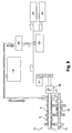
- FIG 8 schematically shows a hybrid transmission 17, such as that described above, which is recognized primary shafts 1, 6 and the secondary shaft 10, the engine 19 and the electric traction machine 7.
- the electric machine 7 is electrically connected to the traction battery 18.
- the heat engine 19 drives an alternator 26 to recharge the board battery 22, supplying the onboard network 23 and the starter 24 of the engine 19.
- the alternator 21 supplies the onboard battery with low voltage current.
- the current flowing between the heat engine 19 and the traction battery 18 is a high voltage current.
- a current converter 26 is arranged between them.
- the converter 26 lowers the voltage of the current flowing from the traction battery 18 to the on-board battery 22, but no charging current can flow from the onboard battery 22 to the traction battery 18.
- the traction battery 18 can therefore be recharged at the roadside stop by the engine running as a generator, with the transmission in neutral according to the figure 1 , but it can not be recharged by the battery board 22.
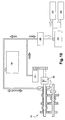
- the two batteries 18, 22 are always connected by the voltage converter 26.
- the converter 26 is now a reversible converter, allowing not only to lower the voltage between the traction battery 18 and the onboard battery 22, but in addition to raising the voltage of a reverse charge current, from the battery board 22 towards the traction battery 18.
- the current can flow in both directions between the two batteries.
- the alternator has been reinforced to meet the energy requirements of the traction battery, at least during takeoff of the vehicle and taxiing at low speed.
- the heat engine and the alternator thus constitute a generator capable of meeting the energy requirements of the electric traction machine during take-off and at low speeds of movement of the vehicle in electric mode.
- the alternator 26 is a high-voltage alternator, for example a rewound alternator, connectable directly to the traction battery 18, without the relay of a voltage converter.
- the latter is always present in the architecture.
- the alternator 21 is now connected to the traction battery 18, between the voltage converter 26 and the latter.
- the heat engine 19 and the alternator 21 constitute a generator capable of meeting the energy requirements of the electric traction machine 7 during take-off and at low speeds of movement of the vehicle in electric mode.
- the onboard battery 22 is outside the charging circuit of the traction battery 7, and the current converter intervenes only for the optional charging of the on-board battery from the traction battery. It no longer needs to be reversible.
- the invention makes it possible to take advantage of the transmission in an additional operating mode, said "hybrid series "in the event of complete discharge of the traction battery, using the electric machine as a source of motive power supplied by the traction battery which is recharged by the engine running as a generator.
- This additional mode can be implemented for a modest cost, for example by re-winding a high voltage alternator associated with a voltage regulation, without requiring the presence of a driving inverter for a second machine.
- this operating mode is possible at least on a first short transmission ratio, up to a speed threshold, beyond which, either the The motive power of the electric machine and that of the electric machine combine in hybrid mode, the only motive power used is the heat engine.
Description
La présente invention concerne l'architecture électrique d'un véhicule comportant un moteur thermique d'entraînement et une machine électrique, reliée aux roues du véhicule par une transmission hybride.The present invention relates to the electrical architecture of a vehicle comprising a drive engine and an electric machine, connected to the vehicle wheels by a hybrid transmission.
Elle a pour objet l'architecture électrique d'un véhicule hybride, dont le moteur thermique entraîne un alternateur de recharge d'une batterie de bord basse tension reliée au démarreur du moteur thermique et au réseau de bord du véhicule, et dont la machine électrique de traction est alimentée par une batterie de traction haute tension pouvant être régénérée par le moteur thermique au point mort.It relates to the electrical architecture of a hybrid vehicle, the heat engine of which drives a charging alternator of a low-voltage onboard battery connected to the starter of the engine and to the on-board vehicle network, and whose electric machine traction is powered by a high voltage traction battery that can be regenerated by the engine in neutral.
Cette invention trouve une application privilégiée sur un véhicule équipé d'une transmission hybride comportant deux arbres primaires concentriques portant chacun au moins un pignon de descente sur un arbre secondaire relié aux roues du véhicule permettant :
- de découpler le moteur thermique de la chaîne cinématique reliant la machine électrique aux roues,
- d'entraîner les roues par le moteur thermique avec ou sans l'appoint de la machine électrique, ou encore
- de coupler le moteur thermique et la machine électrique de manière à additionner en direction des roues, leurs couples respectifs.
- to decouple the heat engine from the kinematic chain connecting the electric machine to the wheels,
- to drive the wheels by the engine with or without the addition of the electric machine, or
- coupling the heat engine and the electric machine so as to add to the wheels, their respective pairs.
Elle porte également sur un véhicule hybride, présentant une telle architecture électrique et sur son procédé de commande.It also relates to a hybrid vehicle, having such an electrical architecture and its control method.
Les transmissions hybrides ont pour intérêt principal de faire bénéficier la chaîne cinématique d'entraînement d'un véhicule, de deux sources d'énergies, thermique et électrique, dont les apports de couple peuvent se cumuler dans un mode dit hybride, ou être utilisées séparément, soit dans un « mode thermique pur » où la machine électrique ne fournit pas de couple à la chaîne de traction, soit dans un mode « électrique pur », où le moteur thermique ne fournit pas de couple à la chaîne de traction. D'autres fonctionnalités sont également requises, telles que la possibilité de lancer le moteur thermique à l'arrêt ou en roulage, en utilisant la machine électrique comme démarreur, ou celle d'utiliser la machine électrique en générateur de courant, pour charger les batteries.Hybrid transmissions have the main interest to benefit the drive train of a vehicle, two sources of energy, thermal and electrical, whose torque contributions can be combined in a so-called hybrid mode, or be used separately either in a "pure thermal mode" where the electric machine does not provide torque to the power train, or in a "Pure electric" mode, where the heat engine does not provide torque to the power train. Other features are also required, such as the ability to start the engine off or running, using the electric machine as a starter, or to use the electric machine as a power generator, to charge the batteries. .
Le problème de l'autonomie et de la recharge des batteries est un problème crucial sur les véhicules hybrides. Pour recharger une batterie de traction complètement déchargée, soit à la suite d'un stationnement prolongé du véhicule, soit en cas d'échec de la stratégie de contrôle du niveau de charge, les véhicules hybrides conventionnels n'ont recours qu'à la « recharge en bord de route », imposant l'immobilisation du véhicule pour faire tourner la machine de traction en générateur à l'aide du moteur thermique.The problem of battery life and recharging is a crucial problem for hybrid vehicles. In order to recharge a fully discharged traction battery, either as a result of prolonged vehicle parking or failure of the load control strategy, conventional hybrid vehicles use only the roadside charging ", imposing the immobilization of the vehicle to rotate the traction machine into a generator using the engine.
La présente invention vise à supprimer cet inconvénient, en assurant les besoins énergétiques de la machine de traction à faible vitesse en cas de décharge complète de la batterie de traction du véhicule.The present invention aims to eliminate this disadvantage, by ensuring the energy requirements of the low-speed traction machine in the event of complete discharge of the traction battery of the vehicle.
Dans ce but, elle propose que le moteur thermique et l'alternateur de recharge de la batterie de bord constituent un groupe électrogène à faible coût, capable d'assurer les besoins énergétiques de la machine électrique de traction en mode électrique.For this purpose, it proposes that the combustion engine and the charging alternator of the on-board battery constitute a low-cost generator set capable of meeting the energy requirements of the electrical traction machine in electric mode.
De préférence, la batterie de traction et la batterie de bord sont reliées par un convertisseur de tension permettant d'abaisser la tension entre la batterie de traction et la batterie de bord.Preferably, the traction battery and the on-board battery are connected by a voltage converter for lowering the voltage between the traction battery and the on-board battery.
Dans un premier mode de réalisation, le convertisseur de tension peut avoir un fonctionnement réversible, lui permettant également d'élever la tension d'un courant de charge circulant de la batterie de bord vers la batterie de traction.In a first embodiment, the voltage converter can have a reversible operation, also enabling it to raise the voltage of a charging current flowing from the onboard battery to the traction battery.
Dans un deuxième mode de réalisation, l'alternateur est un alternateur à haute tension (pouvant par exemple être piloté par son rotor bobiné en haute ou basse tension), connectable directement à la batterie de traction associé ou non à un système de redressement ou de régulation de la tension.In a second embodiment, the alternator is a high-voltage alternator (which may for example be driven by its wound rotor at high or low voltage), connectable directly to the traction battery associated or not with a rectifying system or regulation of the voltage.
D'autres caractéristiques et avantages de l'invention apparaîtront clairement à la lecture de la description suivante d'un mode de réalisation non limitatif de celle-ci, en se reportant aux dessins annexés, sur lesquels :
- la
figure 1 illustre la régénération de la batterie de traction d'un véhicule hybride sur un exemple de transmission hybride au point mort, - les
figures 2 à 7 illustrent les différentes possibilités de fonctionnement de cette transmission, - la
figure 8 illustre une première architecture électrique adaptée à la transmission, - la
figure 9 illustre un premier mode de réalisation de l'invention, et - la
figure 10 illustre un deuxième mode de réalisation de l'invention.
- the
figure 1 illustrates the regeneration of the traction battery of a hybrid vehicle on an example of hybrid transmission in neutral, - the
Figures 2 to 7 illustrate the various possibilities of operation of this transmission, - the
figure 8 illustrates a first electrical architecture adapted to the transmission, - the
figure 9 illustrates a first embodiment of the invention, and - the
figure 10 illustrates a second embodiment of the invention.
La transmission 17 des
Le premier moyen de couplage 5 peut occuper au moins trois positions dans lesquelles :
- le moteur thermique est découplé de la chaîne cinématique reliant la machine électrique 7 aux roues (position 1),
- le moteur thermique entraîne les roues avec ou sans l'appoint de la machine électrique (position 2), et
- le moteur thermique et la machine électrique 7 sont couplés de manière à additionner en direction des roues leurs couples respectifs (position 3).
- the heat engine is decoupled from the kinematic chain connecting the
electric machine 7 to the wheels (position 1), - the heat engine drives the wheels with or without the addition of the electric machine (position 2), and
- the heat engine and the
electric machine 7 are coupled so as to add their respective torques (position 3) in the direction of the wheels.
Sur la
Sur la
Sur la
Sur la
Sur la
Sur la
Sur la
Sur la
Sur la
Sur la figure 11, l'alternateur 26 est un alternateur à haute tension, par exemple un alternateur rembobiné, connectable directement à la batterie de traction 18, sans le relais d'un convertisseur de tension. Ce dernier est toujours présent dans l'architecture. Cependant, l'alternateur 21 est désormais connecté à la batterie de traction 18, entre le convertisseur de tension 26 et celle-ci. Comme précédemment, le moteur thermique 19 et l'alternateur 21, constituent un groupe électrogène capable d'assurer les besoins énergétiques de la machine électrique de traction 7 lors du décollage et aux faibles vitesses de déplacement du véhicule en mode électrique. Cependant, la batterie de bord 22 est en dehors du circuit de charge de la batterie de traction 7, et le convertisseur de courant n'intervient que pour la recharge éventuelle de la batterie de bord à partir de la batterie de traction. Il n'a donc plus besoin d'être réversible.In FIG. 11, the
Lorsque le moteur thermique a démarré (en principe à l'aide du démarreur alimenté par la batterie de bord), il est possible de faire décoller et rouler le véhicule en mode électrique, jusqu'à un certain seuil de vitesse. Le moteur thermique est alors utilisé comme générateur de recharge de la batterie de traction en mode électrique, par l'intermédiaire de la batterie de bord, tandis que toute l'énergie motrice est fournie par la machine électrique 7. Ce fonctionnement est typiquement celui d'un véhicule « hybride série », alors que la transmission est conçue au départ comme celle d'un « hybride parallèle » où le moteur thermique et la machine électrique transmettent tous les deux de l'énergie mécanique aux roues. Il permet de faire décoller le véhicule à partir de l'arrêt et de le faire rouler aux faibles vitesses. Dès que la vitesse de déplacement du véhicule est suffisante pour connecter le moteur thermique aux roues par la transmission, on peut changer de mode et basculer par exemple dans un autre mode, par exemple en mode thermique (
L'invention permet de tirer profit de la transmission dans un mode fonctionnement supplémentaire, dit « hybride série » en cas de décharge compète de la batterie de traction, en utilisant la machine électrique comme une source d'énergie motrice alimentée par la batterie de traction qui est rechargée par le moteur thermique fonctionnant en générateur. Ce mode supplémentaire peut être mis en oeuvre pour un coût modique par exemple par re-bobinage d'un l'alternateur en haute tension associé à une régulation de tension, sans nécessiter la présence d'un onduleur de pilotage pour une deuxième machine. Selon le dimensionnement des organes mécaniques et électriques de la transmission, ce mode fonctionnement, dit « hybride série », est possible au moins sur un premier rapport de transmission court, jusqu'à un seuil de vitesse, au-delà duquel, soit l'énergie motrice de la machine électrique et celle de la machine électrique se cumulent en mode hybride, soit la seule source motrice utilisée est le moteur thermique.The invention makes it possible to take advantage of the transmission in an additional operating mode, said "hybrid series "in the event of complete discharge of the traction battery, using the electric machine as a source of motive power supplied by the traction battery which is recharged by the engine running as a generator. This additional mode can be implemented for a modest cost, for example by re-winding a high voltage alternator associated with a voltage regulation, without requiring the presence of a driving inverter for a second machine. According to the dimensioning of the mechanical and electrical members of the transmission, this operating mode, called "hybrid series", is possible at least on a first short transmission ratio, up to a speed threshold, beyond which, either the The motive power of the electric machine and that of the electric machine combine in hybrid mode, the only motive power used is the heat engine.
Claims (10)
- Electrical architecture of a hybrid motor vehicle comprising a combustion engine (19) driving an alternator (21) that recharges a low-voltage on-board battery (22) connected to the starter (24) of the combustion engine and to the vehicle on-board network (24), an electric traction machine (7) powered by a high-voltage traction battery (18) and a hybrid transmission (17) having coupling means (5) that can occupy at least a first position in which the combustion engine (19) is uncoupled from the drive train connecting the electric machine (7) to the wheels, a second position in which the wheels are driven by the combustion engine (19) with or without top-up from the electric machine (7), and a third position in which the combustion engine (19) and the electric machine (7) are coupled in such a way as to combine their respective torques, bound for the wheels,
characterized in that the combustion engine (19) and the alternator (21) constitute an electricity generator set capable of supplying the energy requirements of the electric traction machine (7) in electric mode. - Electrical architecture according to Claim 1 or 2, characterized in that the two batteries (18, 22) are connected by the voltage transformer (26) enabling the voltage between the traction battery (18) and the on-board battery (22) to be reduced.
- Electrical architecture according to Claim 2, characterized in that the voltage transformer (26) has a reversible functioning enabling it to raise the voltage of a charging current circulating from the on-board battery (22) in the direction of the traction battery (18).
- Electrical architecture according to Claim 1 or 2, characterized in that the alternator (21) is a high-voltage alternator directly connectable to the traction battery (18).
- Electrical architecture according to Claim 4, characterized in that the alternator (21) is connected to the traction battery between the voltage transformer (26) and this battery.
- Hybrid vehicle, characterized in that its electrical architecture conforms to one of the preceding claims.
- Control method of a hybrid vehicle according to Claim 6, characterized in that the combustion engine (19) is used as a generator to recharge the traction battery (18) while the vehicle is traveling in electric mode.
- Control method of a hybrid vehicle according to Claim 7, characterized in that the combustion engine (19) is used as a generator to recharge the traction battery (18) when the vehicle is moving off in electric mode.
- Control method according to Claim 7 or 8, characterized in that one uses the electric machine (7) as the only source of driving energy up to a speed threshold, where one couples the combustion engine to the wheels.
- Control method according to Claim 7, 8 or 9, characterized in that the electric machine (7) is used as the only source of driving energy up to a speed threshold, beyond which one can pass to a hybrid mode or to combustion mode.
Applications Claiming Priority (2)
| Application Number | Priority Date | Filing Date | Title |
|---|---|---|---|
| FR1155753A FR2977198B1 (en) | 2011-06-28 | 2011-06-28 | ELECTRIC HYBRID VEHICLE ARCHITECTURE, HYBRID VEHICLE AND CONTROL METHOD |
| PCT/FR2012/051190 WO2013001194A1 (en) | 2011-06-28 | 2012-05-25 | Electrical architecture of a hybrid vehicle, hybrid vehicle and control method |
Publications (2)
| Publication Number | Publication Date |
|---|---|
| EP2726757A1 EP2726757A1 (en) | 2014-05-07 |
| EP2726757B1 true EP2726757B1 (en) | 2016-09-28 |
Family
ID=46420392
Family Applications (1)
| Application Number | Title | Priority Date | Filing Date |
|---|---|---|---|
| EP12731076.1A Active EP2726757B1 (en) | 2011-06-28 | 2012-05-25 | Electrical architecture of a hybrid vehicle, hybrid vehicle and control method |
Country Status (9)
| Country | Link |
|---|---|
| US (1) | US9453458B2 (en) |
| EP (1) | EP2726757B1 (en) |
| JP (1) | JP6359449B2 (en) |
| KR (1) | KR101904492B1 (en) |
| CN (1) | CN103649588B (en) |
| BR (1) | BR112013033034B1 (en) |
| FR (1) | FR2977198B1 (en) |
| RU (1) | RU2600959C2 (en) |
| WO (1) | WO2013001194A1 (en) |
Cited By (2)
| Publication number | Priority date | Publication date | Assignee | Title |
|---|---|---|---|---|
| WO2018096228A1 (en) * | 2016-11-25 | 2018-05-31 | Renault S.A.S | Method for controlling a hybrid motor vehicle powertrain fitted with a gearbox |
| WO2019096678A1 (en) | 2017-11-15 | 2019-05-23 | Renault S.A.S | Method and system for controlling a clutchless automatic transmission for a hybrid-propulsion motor vehicle |
Families Citing this family (14)
| Publication number | Priority date | Publication date | Assignee | Title |
|---|---|---|---|---|
| FR2973299B1 (en) * | 2011-04-01 | 2013-08-16 | Renault Sa | HYBRID TRANSMISSION FOR MOTOR VEHICLE AND CONTROL METHOD |
| WO2014189649A1 (en) | 2013-04-26 | 2014-11-27 | Avery Dennison Corporation | Apparatus for dispensing pressure sensitive adhesive labels onto a substrate |
| EP3060390B1 (en) | 2013-10-21 | 2020-04-29 | Avery Dennison Corporation | Label assembly and method of dispensing low-stiffness labels |
| US9026296B1 (en) * | 2013-11-08 | 2015-05-05 | Ford Global Technologies, Llc | System for controlling overall coasting torque in a hybrid electric vehicle |
| US20150204393A1 (en) * | 2014-01-21 | 2015-07-23 | GM Global Technology Operations LLC | Dual winding electric actuator for hybrid system |
| FR3030005B1 (en) | 2014-12-15 | 2016-12-09 | Renault Sa | METHOD FOR CONTROLLING A DISENGAGEMENT LIMIT POSITION OF A MOBILE CRABOT FOR TRANSMISSION OF MOTOR VEHICLE AND TRANSMISSION FOR CORRESPONDING MOTOR VEHICLE |
| US10414263B2 (en) * | 2016-04-08 | 2019-09-17 | Hyundai Motor Company | Transmission for vehicle |
| FR3053947B1 (en) * | 2016-07-13 | 2018-08-10 | Renault S.A.S | METHOD OF CONTROLLING THE ORGANS OF A HYBRID TRANSMISSION FOR A MOTOR VEHICLE. |
| FR3061755B1 (en) | 2017-01-12 | 2019-05-10 | Renault S.A.S | METHOD FOR CONTROLLING A LOCOBOX TYPE GEARBOX |
| FR3069497B1 (en) * | 2017-07-26 | 2019-08-02 | Psa Automobiles Sa | METHOD FOR A HYBRID VEHICLE FOR CONTROLLING A RECHARGING ALTERNATOR OF A BATTERY OF A FLIGHT NETWORK |
| FR3079278B1 (en) | 2018-03-23 | 2020-10-09 | Renault Sas | METHOD AND SYSTEM FOR CONTROL OF A GEARBOX ACTUATOR OF A TRANSMISSION FOR HYBRID PROPULSION MOTOR VEHICLE |
| RU2701282C1 (en) * | 2018-12-17 | 2019-09-25 | Акционерное общество "АвтоВАЗ" (АО "АвтоВАЗ") | Vehicle with hybrid power plant |
| DE102022102988A1 (en) | 2022-02-09 | 2023-08-10 | Schaeffler Technologies AG & Co. KG | Torsional vibration damper system and drive train for a motor vehicle |
| WO2024044489A1 (en) * | 2022-08-24 | 2024-02-29 | Cummins Inc. | Apparatuses, methods, and systems including hybrid powertrains with positive clutches |
Citations (8)
| Publication number | Priority date | Publication date | Assignee | Title |
|---|---|---|---|---|
| DE4431929C1 (en) | 1994-09-08 | 1995-10-26 | Daimler Benz Ag | Hybrid drive system for motor vehicles with IC engine and electromotor |
| US20010039230A1 (en) | 1998-09-14 | 2001-11-08 | Severinsky Alex J. | Hybrid vehicles |
| EP1671832A2 (en) | 2004-12-20 | 2006-06-21 | Denso Corporation | Electric wheel drive apparatus |
| DE102006014152A1 (en) | 2005-03-29 | 2006-11-16 | Mitsubishi Fuso Truck And Bus Corp. | Battery charging system for hybrid electric vehicles |
| DE60128905T2 (en) | 2000-04-27 | 2008-02-07 | Mitsubishi Fuso Truck And Bus Corp. | CONTROL OF THE MOTOR FUNCTION OF A HYBRID VEHICLE |
| EP2062770A1 (en) | 2007-11-23 | 2009-05-27 | hofer forschungs- und entwicklungs GmbH & Co KG | Drive system for motor vehicles |
| WO2010070707A1 (en) | 2008-12-18 | 2010-06-24 | 本田技研工業株式会社 | Power transmission device for hybrid vehicle |
| EP2585328A1 (en) | 2010-06-28 | 2013-05-01 | ZF Friedrichshafen AG | Hybrid drive having an automated conventional gearbox |
Family Cites Families (14)
| Publication number | Priority date | Publication date | Assignee | Title |
|---|---|---|---|---|
| GB8323482D0 (en) * | 1983-09-01 | 1983-10-05 | Lucas Chloride Ev Syst Ltd | Vehicle propulsion system |
| JP2795051B2 (en) * | 1992-05-15 | 1998-09-10 | 三菱自動車工業株式会社 | How to drive a hybrid car |
| JP3775012B2 (en) * | 1997-08-29 | 2006-05-17 | アイシン・エィ・ダブリュ株式会社 | Hybrid drive device for vehicle |
| JP2001333506A (en) * | 2000-05-23 | 2001-11-30 | Hitachi Ltd | Hybrid vehicle and control method therefor |
| JP2003237393A (en) * | 2002-02-12 | 2003-08-27 | Aisin Ai Co Ltd | Transmission device with power source |
| JP3875208B2 (en) * | 2003-04-11 | 2007-01-31 | 日本車輌製造株式会社 | Hybrid vehicle emergency driving system |
| JP4094591B2 (en) * | 2004-08-10 | 2008-06-04 | 富士重工業株式会社 | Drive device for hybrid vehicle |
| US7689331B2 (en) | 2004-12-01 | 2010-03-30 | Ise Corporation | Method of controlling engine stop-start operation for heavy-duty hybrid-electric and hybrid-hydraulic vehicles |
| US7689330B2 (en) | 2004-12-01 | 2010-03-30 | Ise Corporation | Method of controlling engine stop-start operation for heavy-duty hybrid-electric and hybrid-hydraulic vehicles |
| JP2006211859A (en) * | 2005-01-31 | 2006-08-10 | Toyota Motor Corp | Device for controlling vehicle |
| US7832513B2 (en) * | 2006-07-14 | 2010-11-16 | Gm Global Technology Operations, Inc. | Vehicular electrical system and control method therefor |
| CN200967407Y (en) * | 2006-08-30 | 2007-10-31 | 霍树恒 | Hybrid electric dual-purpose automobile power assembly |
| JP2009292215A (en) * | 2008-06-03 | 2009-12-17 | Aisin Ai Co Ltd | Power transmission device for hybrid vehicle and gear shift operation method thereof |
| FR2933357B1 (en) * | 2008-07-02 | 2011-02-11 | Peugeot Citroen Automobiles Sa | MULTI VOLTAGE ELECTRICAL MANAGEMENT SYSTEM FOR A HYBRID VEHICLE. |
-
2011
- 2011-06-28 FR FR1155753A patent/FR2977198B1/en active Active
-
2012
- 2012-05-25 CN CN201280034569.9A patent/CN103649588B/en active Active
- 2012-05-25 KR KR1020147001202A patent/KR101904492B1/en active IP Right Grant
- 2012-05-25 US US14/129,825 patent/US9453458B2/en active Active
- 2012-05-25 EP EP12731076.1A patent/EP2726757B1/en active Active
- 2012-05-25 JP JP2014517877A patent/JP6359449B2/en active Active
- 2012-05-25 WO PCT/FR2012/051190 patent/WO2013001194A1/en active Application Filing
- 2012-05-25 RU RU2014102607/11A patent/RU2600959C2/en active
- 2012-05-25 BR BR112013033034-1A patent/BR112013033034B1/en active IP Right Grant
Patent Citations (8)
| Publication number | Priority date | Publication date | Assignee | Title |
|---|---|---|---|---|
| DE4431929C1 (en) | 1994-09-08 | 1995-10-26 | Daimler Benz Ag | Hybrid drive system for motor vehicles with IC engine and electromotor |
| US20010039230A1 (en) | 1998-09-14 | 2001-11-08 | Severinsky Alex J. | Hybrid vehicles |
| DE60128905T2 (en) | 2000-04-27 | 2008-02-07 | Mitsubishi Fuso Truck And Bus Corp. | CONTROL OF THE MOTOR FUNCTION OF A HYBRID VEHICLE |
| EP1671832A2 (en) | 2004-12-20 | 2006-06-21 | Denso Corporation | Electric wheel drive apparatus |
| DE102006014152A1 (en) | 2005-03-29 | 2006-11-16 | Mitsubishi Fuso Truck And Bus Corp. | Battery charging system for hybrid electric vehicles |
| EP2062770A1 (en) | 2007-11-23 | 2009-05-27 | hofer forschungs- und entwicklungs GmbH & Co KG | Drive system for motor vehicles |
| WO2010070707A1 (en) | 2008-12-18 | 2010-06-24 | 本田技研工業株式会社 | Power transmission device for hybrid vehicle |
| EP2585328A1 (en) | 2010-06-28 | 2013-05-01 | ZF Friedrichshafen AG | Hybrid drive having an automated conventional gearbox |
Cited By (3)
| Publication number | Priority date | Publication date | Assignee | Title |
|---|---|---|---|---|
| WO2018096228A1 (en) * | 2016-11-25 | 2018-05-31 | Renault S.A.S | Method for controlling a hybrid motor vehicle powertrain fitted with a gearbox |
| FR3059289A1 (en) * | 2016-11-25 | 2018-06-01 | Renault S.A.S | METHOD FOR CONTROLLING A MOTOR VEHICLE HYBRID MOTOR PUSH WITH A GEAR BOX |
| WO2019096678A1 (en) | 2017-11-15 | 2019-05-23 | Renault S.A.S | Method and system for controlling a clutchless automatic transmission for a hybrid-propulsion motor vehicle |
Also Published As
| Publication number | Publication date |
|---|---|
| CN103649588B (en) | 2016-08-17 |
| WO2013001194A1 (en) | 2013-01-03 |
| BR112013033034B1 (en) | 2021-09-08 |
| KR20140044858A (en) | 2014-04-15 |
| US20140290592A1 (en) | 2014-10-02 |
| JP2014521541A (en) | 2014-08-28 |
| RU2600959C2 (en) | 2016-10-27 |
| JP6359449B2 (en) | 2018-07-18 |
| KR101904492B1 (en) | 2018-10-04 |
| US9453458B2 (en) | 2016-09-27 |
| RU2014102607A (en) | 2015-08-10 |
| FR2977198A1 (en) | 2013-01-04 |
| BR112013033034A2 (en) | 2017-01-31 |
| FR2977198B1 (en) | 2013-08-09 |
| EP2726757A1 (en) | 2014-05-07 |
| CN103649588A (en) | 2014-03-19 |
Similar Documents
| Publication | Publication Date | Title |
|---|---|---|
| EP2726757B1 (en) | Electrical architecture of a hybrid vehicle, hybrid vehicle and control method | |
| EP2694309B2 (en) | Hybrid transmission for a motor vehicle, and control method | |
| US9475481B2 (en) | Powertrain for a vehicle | |
| EP3013618B1 (en) | Hybrid transmission with an additional electric machine | |
| EP3160786A1 (en) | Hybrid transmission with offset electric machine and method for controlling gear changes | |
| EP2771199B1 (en) | Three-shaft hybrid transmission for a motor vehicle and control method | |
| EP2834097A1 (en) | Method for controlling recharging of the battery on a hybrid vehicle | |
| EP2558317A1 (en) | Hybrid drive system | |
| JP6542779B2 (en) | Automotive transmission with hybrid propulsion and related control techniques | |
| US10046635B2 (en) | Powertrain for a hybrid type vehicle | |
| KR20190072748A (en) | Method for controlling reverse drive of hybrid vehicle | |
| WO2013117463A1 (en) | Hybrid transmission for motor vehicle with air conditioning compressor drive | |
| FR3065920B1 (en) | TENSION ARCHITECTURE FOR A MOTOR VEHICLE COMPRISING TWO REVERSIBLE ROTATING ELECTRIC MACHINES | |
| FR2745243A1 (en) | Hybrid electric vehicle with electromagnetic coupler between motors | |
| EP3077240B1 (en) | Method for starting the engine of a hybrid powertrain | |
| FR3064575A1 (en) | DEVICE FOR MONITORING THE COUPLINGS / DECOUPLAGES OF A NON-THERMAL MOTOR MACHINE OF A VEHICLE BASED ON A PARAMETER OF STATE OF ASSOCIATED STORAGE MEANS | |
| WO2018229212A1 (en) | Traction structure provided with a device for two-stage coupling between a rotating electrical machine and a rear axle of a motor vehicle | |
| EP3297863B1 (en) | Hybrid transmission having dual shaft coupling, and method for controlling gear changes | |
| FR3065919A1 (en) | TENSION ARCHITECTURE FOR MOTOR VEHICLE INTEGRATING TWO REVERSIBLE ROTATING ELECTRIC MACHINES | |
| FR3001187A3 (en) | Hybrid transmission for motor vehicle, has concentric primary shafts, and coupling unit formed between output shaft and idler gear, where idler gear has higher transmission ratio than hollow shaft connected to electric machine | |
| WO2012160286A1 (en) | Vehicle with manual gearbox equipped with a hybrid power train and associated hybridizing method |
Legal Events
| Date | Code | Title | Description |
|---|---|---|---|
| PUAI | Public reference made under article 153(3) epc to a published international application that has entered the european phase |
Free format text: ORIGINAL CODE: 0009012 |
|
| 17P | Request for examination filed |
Effective date: 20131128 |
|
| AK | Designated contracting states |
Kind code of ref document: A1 Designated state(s): AL AT BE BG CH CY CZ DE DK EE ES FI FR GB GR HR HU IE IS IT LI LT LU LV MC MK MT NL NO PL PT RO RS SE SI SK SM TR |
|
| DAX | Request for extension of the european patent (deleted) | ||
| REG | Reference to a national code |
Ref country code: DE Ref legal event code: R079 Ref document number: 602012023509 Country of ref document: DE Free format text: PREVIOUS MAIN CLASS: F16H0003000000 Ipc: B60K0006280000 |
|
| RIC1 | Information provided on ipc code assigned before grant |
Ipc: B60K 6/48 20071001ALI20151217BHEP Ipc: B60K 6/28 20071001AFI20151217BHEP Ipc: F02B 63/04 20060101ALI20151217BHEP Ipc: F16H 3/089 20060101ALI20151217BHEP |
|
| GRAP | Despatch of communication of intention to grant a patent |
Free format text: ORIGINAL CODE: EPIDOSNIGR1 |
|
| INTG | Intention to grant announced |
Effective date: 20160127 |
|
| GRAS | Grant fee paid |
Free format text: ORIGINAL CODE: EPIDOSNIGR3 |
|
| GRAA | (expected) grant |
Free format text: ORIGINAL CODE: 0009210 |
|
| AK | Designated contracting states |
Kind code of ref document: B1 Designated state(s): AL AT BE BG CH CY CZ DE DK EE ES FI FR GB GR HR HU IE IS IT LI LT LU LV MC MK MT NL NO PL PT RO RS SE SI SK SM TR |
|
| REG | Reference to a national code |
Ref country code: GB Ref legal event code: FG4D Free format text: NOT ENGLISH |
|
| REG | Reference to a national code |
Ref country code: CH Ref legal event code: EP |
|
| REG | Reference to a national code |
Ref country code: AT Ref legal event code: REF Ref document number: 832419 Country of ref document: AT Kind code of ref document: T Effective date: 20161015 |
|
| REG | Reference to a national code |
Ref country code: IE Ref legal event code: FG4D Free format text: LANGUAGE OF EP DOCUMENT: FRENCH |
|
| REG | Reference to a national code |
Ref country code: DE Ref legal event code: R096 Ref document number: 602012023509 Country of ref document: DE |
|
| REG | Reference to a national code |
Ref country code: LT Ref legal event code: MG4D |
|
| PG25 | Lapsed in a contracting state [announced via postgrant information from national office to epo] |
Ref country code: HR Free format text: LAPSE BECAUSE OF FAILURE TO SUBMIT A TRANSLATION OF THE DESCRIPTION OR TO PAY THE FEE WITHIN THE PRESCRIBED TIME-LIMIT Effective date: 20160928 Ref country code: NO Free format text: LAPSE BECAUSE OF FAILURE TO SUBMIT A TRANSLATION OF THE DESCRIPTION OR TO PAY THE FEE WITHIN THE PRESCRIBED TIME-LIMIT Effective date: 20161228 Ref country code: RS Free format text: LAPSE BECAUSE OF FAILURE TO SUBMIT A TRANSLATION OF THE DESCRIPTION OR TO PAY THE FEE WITHIN THE PRESCRIBED TIME-LIMIT Effective date: 20160928 Ref country code: FI Free format text: LAPSE BECAUSE OF FAILURE TO SUBMIT A TRANSLATION OF THE DESCRIPTION OR TO PAY THE FEE WITHIN THE PRESCRIBED TIME-LIMIT Effective date: 20160928 Ref country code: LT Free format text: LAPSE BECAUSE OF FAILURE TO SUBMIT A TRANSLATION OF THE DESCRIPTION OR TO PAY THE FEE WITHIN THE PRESCRIBED TIME-LIMIT Effective date: 20160928 |
|
| REG | Reference to a national code |
Ref country code: NL Ref legal event code: MP Effective date: 20160928 |
|
| REG | Reference to a national code |
Ref country code: AT Ref legal event code: MK05 Ref document number: 832419 Country of ref document: AT Kind code of ref document: T Effective date: 20160928 |
|
| PG25 | Lapsed in a contracting state [announced via postgrant information from national office to epo] |
Ref country code: GR Free format text: LAPSE BECAUSE OF FAILURE TO SUBMIT A TRANSLATION OF THE DESCRIPTION OR TO PAY THE FEE WITHIN THE PRESCRIBED TIME-LIMIT Effective date: 20161229 Ref country code: SE Free format text: LAPSE BECAUSE OF FAILURE TO SUBMIT A TRANSLATION OF THE DESCRIPTION OR TO PAY THE FEE WITHIN THE PRESCRIBED TIME-LIMIT Effective date: 20160928 Ref country code: LV Free format text: LAPSE BECAUSE OF FAILURE TO SUBMIT A TRANSLATION OF THE DESCRIPTION OR TO PAY THE FEE WITHIN THE PRESCRIBED TIME-LIMIT Effective date: 20160928 Ref country code: NL Free format text: LAPSE BECAUSE OF FAILURE TO SUBMIT A TRANSLATION OF THE DESCRIPTION OR TO PAY THE FEE WITHIN THE PRESCRIBED TIME-LIMIT Effective date: 20160928 |
|
| PG25 | Lapsed in a contracting state [announced via postgrant information from national office to epo] |
Ref country code: EE Free format text: LAPSE BECAUSE OF FAILURE TO SUBMIT A TRANSLATION OF THE DESCRIPTION OR TO PAY THE FEE WITHIN THE PRESCRIBED TIME-LIMIT Effective date: 20160928 Ref country code: RO Free format text: LAPSE BECAUSE OF FAILURE TO SUBMIT A TRANSLATION OF THE DESCRIPTION OR TO PAY THE FEE WITHIN THE PRESCRIBED TIME-LIMIT Effective date: 20160928 |
|
| REG | Reference to a national code |
Ref country code: FR Ref legal event code: PLFP Year of fee payment: 6 |
|
| PG25 | Lapsed in a contracting state [announced via postgrant information from national office to epo] |
Ref country code: PL Free format text: LAPSE BECAUSE OF FAILURE TO SUBMIT A TRANSLATION OF THE DESCRIPTION OR TO PAY THE FEE WITHIN THE PRESCRIBED TIME-LIMIT Effective date: 20160928 Ref country code: IS Free format text: LAPSE BECAUSE OF FAILURE TO SUBMIT A TRANSLATION OF THE DESCRIPTION OR TO PAY THE FEE WITHIN THE PRESCRIBED TIME-LIMIT Effective date: 20170128 Ref country code: ES Free format text: LAPSE BECAUSE OF FAILURE TO SUBMIT A TRANSLATION OF THE DESCRIPTION OR TO PAY THE FEE WITHIN THE PRESCRIBED TIME-LIMIT Effective date: 20160928 Ref country code: SM Free format text: LAPSE BECAUSE OF FAILURE TO SUBMIT A TRANSLATION OF THE DESCRIPTION OR TO PAY THE FEE WITHIN THE PRESCRIBED TIME-LIMIT Effective date: 20160928 Ref country code: PT Free format text: LAPSE BECAUSE OF FAILURE TO SUBMIT A TRANSLATION OF THE DESCRIPTION OR TO PAY THE FEE WITHIN THE PRESCRIBED TIME-LIMIT Effective date: 20170130 Ref country code: CZ Free format text: LAPSE BECAUSE OF FAILURE TO SUBMIT A TRANSLATION OF THE DESCRIPTION OR TO PAY THE FEE WITHIN THE PRESCRIBED TIME-LIMIT Effective date: 20160928 Ref country code: SK Free format text: LAPSE BECAUSE OF FAILURE TO SUBMIT A TRANSLATION OF THE DESCRIPTION OR TO PAY THE FEE WITHIN THE PRESCRIBED TIME-LIMIT Effective date: 20160928 Ref country code: BG Free format text: LAPSE BECAUSE OF FAILURE TO SUBMIT A TRANSLATION OF THE DESCRIPTION OR TO PAY THE FEE WITHIN THE PRESCRIBED TIME-LIMIT Effective date: 20161228 Ref country code: AT Free format text: LAPSE BECAUSE OF FAILURE TO SUBMIT A TRANSLATION OF THE DESCRIPTION OR TO PAY THE FEE WITHIN THE PRESCRIBED TIME-LIMIT Effective date: 20160928 |
|
| REG | Reference to a national code |
Ref country code: DE Ref legal event code: R026 Ref document number: 602012023509 Country of ref document: DE |
|
| PG25 | Lapsed in a contracting state [announced via postgrant information from national office to epo] |
Ref country code: IT Free format text: LAPSE BECAUSE OF FAILURE TO SUBMIT A TRANSLATION OF THE DESCRIPTION OR TO PAY THE FEE WITHIN THE PRESCRIBED TIME-LIMIT Effective date: 20160928 |
|
| PLBI | Opposition filed |
Free format text: ORIGINAL CODE: 0009260 |
|
| PG25 | Lapsed in a contracting state [announced via postgrant information from national office to epo] |
Ref country code: DK Free format text: LAPSE BECAUSE OF FAILURE TO SUBMIT A TRANSLATION OF THE DESCRIPTION OR TO PAY THE FEE WITHIN THE PRESCRIBED TIME-LIMIT Effective date: 20160928 |
|
| 26 | Opposition filed |
Opponent name: ZF FRIEDRICHSHAFEN AG Effective date: 20170628 |
|
| PLAX | Notice of opposition and request to file observation + time limit sent |
Free format text: ORIGINAL CODE: EPIDOSNOBS2 |
|
| PG25 | Lapsed in a contracting state [announced via postgrant information from national office to epo] |
Ref country code: LU Free format text: LAPSE BECAUSE OF NON-PAYMENT OF DUE FEES Effective date: 20170531 |
|
| PG25 | Lapsed in a contracting state [announced via postgrant information from national office to epo] |
Ref country code: SI Free format text: LAPSE BECAUSE OF FAILURE TO SUBMIT A TRANSLATION OF THE DESCRIPTION OR TO PAY THE FEE WITHIN THE PRESCRIBED TIME-LIMIT Effective date: 20160928 |
|
| PLBB | Reply of patent proprietor to notice(s) of opposition received |
Free format text: ORIGINAL CODE: EPIDOSNOBS3 |
|
| REG | Reference to a national code |
Ref country code: CH Ref legal event code: PL |
|
| PG25 | Lapsed in a contracting state [announced via postgrant information from national office to epo] |
Ref country code: MC Free format text: LAPSE BECAUSE OF FAILURE TO SUBMIT A TRANSLATION OF THE DESCRIPTION OR TO PAY THE FEE WITHIN THE PRESCRIBED TIME-LIMIT Effective date: 20160928 |
|
| REG | Reference to a national code |
Ref country code: IE Ref legal event code: MM4A |
|
| PG25 | Lapsed in a contracting state [announced via postgrant information from national office to epo] |
Ref country code: CH Free format text: LAPSE BECAUSE OF NON-PAYMENT OF DUE FEES Effective date: 20170531 Ref country code: LI Free format text: LAPSE BECAUSE OF NON-PAYMENT OF DUE FEES Effective date: 20170531 |
|
| PG25 | Lapsed in a contracting state [announced via postgrant information from national office to epo] |
Ref country code: LU Free format text: LAPSE BECAUSE OF NON-PAYMENT OF DUE FEES Effective date: 20170525 |
|
| REG | Reference to a national code |
Ref country code: BE Ref legal event code: MM Effective date: 20170531 |
|
| PG25 | Lapsed in a contracting state [announced via postgrant information from national office to epo] |
Ref country code: IE Free format text: LAPSE BECAUSE OF NON-PAYMENT OF DUE FEES Effective date: 20170525 |
|
| REG | Reference to a national code |
Ref country code: FR Ref legal event code: PLFP Year of fee payment: 7 |
|
| PG25 | Lapsed in a contracting state [announced via postgrant information from national office to epo] |
Ref country code: BE Free format text: LAPSE BECAUSE OF NON-PAYMENT OF DUE FEES Effective date: 20170531 |
|
| PG25 | Lapsed in a contracting state [announced via postgrant information from national office to epo] |
Ref country code: MT Free format text: LAPSE BECAUSE OF FAILURE TO SUBMIT A TRANSLATION OF THE DESCRIPTION OR TO PAY THE FEE WITHIN THE PRESCRIBED TIME-LIMIT Effective date: 20160928 |
|
| PG25 | Lapsed in a contracting state [announced via postgrant information from national office to epo] |
Ref country code: AL Free format text: LAPSE BECAUSE OF FAILURE TO SUBMIT A TRANSLATION OF THE DESCRIPTION OR TO PAY THE FEE WITHIN THE PRESCRIBED TIME-LIMIT Effective date: 20160928 |
|
| PLCK | Communication despatched that opposition was rejected |
Free format text: ORIGINAL CODE: EPIDOSNREJ1 |
|
| STAA | Information on the status of an ep patent application or granted ep patent |
Free format text: STATUS: THE PATENT HAS BEEN GRANTED |
|
| REG | Reference to a national code |
Ref country code: DE Ref legal event code: R100 Ref document number: 602012023509 Country of ref document: DE |
|
| RIC2 | Information provided on ipc code assigned after grant |
Ipc: F16H 3/089 20060101ALI20151217BHEP Ipc: B60K 6/48 20071001ALI20151217BHEP Ipc: F02B 63/04 20060101ALI20151217BHEP Ipc: B60K 6/28 20071001AFI20151217BHEP |
|
| PLBN | Opposition rejected |
Free format text: ORIGINAL CODE: 0009273 |
|
| STAA | Information on the status of an ep patent application or granted ep patent |
Free format text: STATUS: OPPOSITION REJECTED |
|
| 27O | Opposition rejected |
Effective date: 20190208 |
|
| PG25 | Lapsed in a contracting state [announced via postgrant information from national office to epo] |
Ref country code: HU Free format text: LAPSE BECAUSE OF FAILURE TO SUBMIT A TRANSLATION OF THE DESCRIPTION OR TO PAY THE FEE WITHIN THE PRESCRIBED TIME-LIMIT; INVALID AB INITIO Effective date: 20120525 |
|
| PG25 | Lapsed in a contracting state [announced via postgrant information from national office to epo] |
Ref country code: CY Free format text: LAPSE BECAUSE OF NON-PAYMENT OF DUE FEES Effective date: 20160928 |
|
| PG25 | Lapsed in a contracting state [announced via postgrant information from national office to epo] |
Ref country code: MK Free format text: LAPSE BECAUSE OF FAILURE TO SUBMIT A TRANSLATION OF THE DESCRIPTION OR TO PAY THE FEE WITHIN THE PRESCRIBED TIME-LIMIT Effective date: 20160928 |
|
| PG25 | Lapsed in a contracting state [announced via postgrant information from national office to epo] |
Ref country code: TR Free format text: LAPSE BECAUSE OF FAILURE TO SUBMIT A TRANSLATION OF THE DESCRIPTION OR TO PAY THE FEE WITHIN THE PRESCRIBED TIME-LIMIT Effective date: 20160928 |
|
| P01 | Opt-out of the competence of the unified patent court (upc) registered |
Effective date: 20230608 |
|
| PGFP | Annual fee paid to national office [announced via postgrant information from national office to epo] |
Ref country code: FR Payment date: 20230526 Year of fee payment: 12 Ref country code: DE Payment date: 20230519 Year of fee payment: 12 |
|
| PGFP | Annual fee paid to national office [announced via postgrant information from national office to epo] |
Ref country code: GB Payment date: 20230524 Year of fee payment: 12 |
|
| REG | Reference to a national code |
Ref country code: GB Ref legal event code: 732E Free format text: REGISTERED BETWEEN 20231228 AND 20240103 |