EP2732779A1 - Bipolar coagulation instrument - Google Patents
Bipolar coagulation instrument Download PDFInfo
- Publication number
- EP2732779A1 EP2732779A1 EP13193121.4A EP13193121A EP2732779A1 EP 2732779 A1 EP2732779 A1 EP 2732779A1 EP 13193121 A EP13193121 A EP 13193121A EP 2732779 A1 EP2732779 A1 EP 2732779A1
- Authority
- EP
- European Patent Office
- Prior art keywords
- shaft tube
- instrument according
- bipolar coagulation
- coagulation instrument
- trigger
- Prior art date
- Legal status (The legal status is an assumption and is not a legal conclusion. Google has not performed a legal analysis and makes no representation as to the accuracy of the status listed.)
- Withdrawn
Links
Images


Classifications
-
- A—HUMAN NECESSITIES
- A61—MEDICAL OR VETERINARY SCIENCE; HYGIENE
- A61B—DIAGNOSIS; SURGERY; IDENTIFICATION
- A61B17/00—Surgical instruments, devices or methods, e.g. tourniquets
- A61B17/28—Surgical forceps
- A61B17/29—Forceps for use in minimally invasive surgery
-
- A—HUMAN NECESSITIES
- A61—MEDICAL OR VETERINARY SCIENCE; HYGIENE
- A61B—DIAGNOSIS; SURGERY; IDENTIFICATION
- A61B17/00—Surgical instruments, devices or methods, e.g. tourniquets
- A61B17/28—Surgical forceps
- A61B17/29—Forceps for use in minimally invasive surgery
- A61B17/295—Forceps for use in minimally invasive surgery combined with cutting implements
-
- A—HUMAN NECESSITIES
- A61—MEDICAL OR VETERINARY SCIENCE; HYGIENE
- A61B—DIAGNOSIS; SURGERY; IDENTIFICATION
- A61B18/00—Surgical instruments, devices or methods for transferring non-mechanical forms of energy to or from the body
- A61B18/04—Surgical instruments, devices or methods for transferring non-mechanical forms of energy to or from the body by heating
- A61B18/12—Surgical instruments, devices or methods for transferring non-mechanical forms of energy to or from the body by heating by passing a current through the tissue to be heated, e.g. high-frequency current
- A61B18/14—Probes or electrodes therefor
- A61B18/1402—Probes for open surgery
-
- A—HUMAN NECESSITIES
- A61—MEDICAL OR VETERINARY SCIENCE; HYGIENE
- A61B—DIAGNOSIS; SURGERY; IDENTIFICATION
- A61B18/00—Surgical instruments, devices or methods for transferring non-mechanical forms of energy to or from the body
- A61B18/04—Surgical instruments, devices or methods for transferring non-mechanical forms of energy to or from the body by heating
- A61B18/12—Surgical instruments, devices or methods for transferring non-mechanical forms of energy to or from the body by heating by passing a current through the tissue to be heated, e.g. high-frequency current
- A61B18/14—Probes or electrodes therefor
- A61B2018/1495—Electrodes being detachable from a support structure
Definitions
- the invention relates to a bipolar coagulation instrument according to the preamble of patent claim 1.
- Bipolar coagulation instruments are known with a shaft tube, at the distal end of a working element is arranged, which has two mutually pivotable jaws, each with a coagulation plate and a movable knife.
- the jaw parts are mutually pivotable by means of two arranged at the proximal end of the shaft tube, mutually pivotable handle parts.
- a trigger is arranged at the proximal end of the shaft tube, by means of which the knife is movable.
- the object of the invention is to develop a known bipolar Koagulationsinstrument, in particular such that it has a longer life or safer to handle.
- the bipolar coagulation instrument with a shaft tube, with a working element arranged at the distal end of the shaft tube, which has two jaw parts which can be pivoted against one another by means of two grip parts arranged at the proximal end of the shaft tube and pivotable relative to one another. which each have a coagulation plate, and a movable means of a arranged at the proximal end of the shaft tube trigger knife, characterized in that the knife is interchangeable. Especially the knife wears quickly when using the bipolar coagulation instrument and is difficult to clean.
- An interchangeable knife wherein only the blade arranged in the working element is replaced without the actuating mechanism arranged in the shaft tube, has the advantage that a wearing part can be exchanged cost-effectively, which improves the service life and possible use of the bipolar coagulation instrument.
- a particularly preferred embodiment of the invention provides that the knife is replaceable from the distal end. This simplifies the handle of the instrument, as in contrast to known Koagulationsinstrumenten in which the knife including the actuating mechanism from the proximal end of the shaft tube forth pulled out of the shaft tube and completely replaced, a faster and easier and cheaper replacement is possible.
- An advantageous embodiment of the invention provides that the knife can be plugged into a knife receptacle and there interchangeable lockable, preferably latched by means of a latching connection, is. This allows easy attachment of the knife and easy replacement.
- the locking connection has a bore and a latching in the bore ball head, which allows easy locking of the blade in the blade holder.
- the blade holder is pivotally mounted about a pivot axis and connected via a guided through the shaft tube actuating rod with the trigger. This allows easy operation of the knife.
- the knife is arranged sunk through a slot in one of the coagulation plates in a jaw part.
- An advantageous embodiment of the invention provides that the trigger has a safety device in order to avoid accidental release of the trigger, which causes a cutting of the blade can.
- the safety device has a latching mechanism which is to be overcome by a movement transverse to the movement of the trigger before the trigger can be actuated. Due to the two different directions of movement for moving the trigger on the one hand and to solve the safety device on the other hand, it is less likely that the trigger is operated by mistake.
- the trigger on a curved T-groove in which a spring, in particular a curved leaf spring is guided, on which a locking pin is arranged, which engages in a position in a locking bore on the T-groove.
- the engagement is effected by the spring, so that a release of the locking bolt from the recess takes place against the force of the spring and then the trigger can be actuated such that the Spring, in particular the curved leaf spring, is guided displaceably in the curved T-slot.
- a further bipolar coagulation instrument with a shaft tube, with a working element arranged at the distal end of the shaft tube, which has two jaw parts which can be pivoted relative to one another by means of two gripping parts which are arranged at the proximal end of the shaft tube and each have a coagulation plate.
- the coagulation plates are arranged isolated in the respective jaw parts by means of a jaw part insert. This makes it possible that only the isolated coagulation plates are energized, so that isolation of the shaft tube can be omitted.
- the jaw member insert is cupped to completely surround the coagulation plate apart from the side surface of the coagulation plate facing the other coagulation plate.
- each of the coagulation plates is connected via an insulated electrical conductor to a power connection arranged at the proximal end of the shaft tube, whereby current can be applied to the coagulation plates in a simple manner, without the need for additional measures for isolation on the shaft tube.
- a locking device is provided for the jaw part, which locks the jaw parts in a position against each other, so that a pivoting of the jaws against each other is prevented. This allows pinching tissue between the two jaws for coagulation and subsequent cutting.
- the locking device has a locking element, in particular in the form of a leaf spring, with a latching hook, which is arranged on the shaft tube or a rigidly connected to the shaft tube element, wherein the latching hook engages in a latching projection which on the pivotable relative to the shaft tube handle part or a connected to the pivotable relative to the shaft tube handle member, such as a pull rod for the pivotable jaw part, is arranged.
- a locking element in particular in the form of a leaf spring
- a latching hook which is arranged on the shaft tube or a rigidly connected to the shaft tube element, wherein the latching hook engages in a latching projection which on the pivotable relative to the shaft tube handle part or a connected to the pivotable relative to the shaft tube handle member, such as a pull rod for the pivotable jaw part, is arranged.
- FIG. 1 shows a coagulation instrument 10 with a shaft tube 20, which has a distal end 20a and a proximal end 20b.
- a working end 30 is arranged, which has a first jaw part 31 and a second jaw part 32, which are mutually pivotable.
- the first jaw part 31 is rigidly connected to the shaft tube 20.
- the second jaw part 32 is about a pivot axis 32a (see FIGS. 4a to 4f ) mounted pivotally mounted on the shaft tube 20.
- the first jaw part 31 has a first coagulation plate 33.
- the second jaw part 32 has a second coagulation plate 34.
- the first coagulation plate 33 is arranged in the first jaw part 31 in an insulating manner by means of a jaw part insert 35, which in particular may be shell-shaped.
- the second coagulation plate 34 is arranged in the second jaw part 32 in an insulated manner by means of a jaw part insert 36, which may also be shell-shaped.
- the first coagulation plate 33 is connected via an electrical conductor, not shown, to a first contact element 23 of a power connection 22, which is arranged at the proximal end 20b of the shaft tube 20, while the second coagulation plate 34 is connected via a further, not shown, electrical conductor to a second contact element 24 of the power connector 22 is electrically connected.
- the Koagulationsinstrument 10 has two mutually pivotable handle parts 41, 42.
- the first grip part 41 can be rigidly connected to the shaft tube 20, while the second grip part 42 is arranged pivotably about a pivot axis 44 against the first grip part 41.
- the second handle portion 42 is hinged to the proximal end of a Actuating rod 32b is connected, which is guided by the shaft tube 20 and at the distal end of the pivot axis 32a forming the second jaw part 32 is connected.
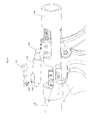
- FIGS. 3a to 3d An optional locking device 100 for the pivoting movement of the second jaw part 32 is in the FIGS. 3a to 3d shown.
- the proximal end of the actuating rod 32b is not directly connected to the pivotable second handle portion 42, but the connection is made by means of a sleeve 105, a collet 106 and a ball head 107.
- the proximal end of the actuating rod 32b is inserted into a distal end of a collet 106 ,
- the collet 106 is disposed in a sleeve 105.
- the proximal end of the collet 106 cooperates with a connecting portion of a ball head 107.
- the ball head 107 is inserted into a corresponding recess on the pivotable second handle part 42.
- the collet 106 axially displaceable in the sleeve 106, the distance between the second handle part 42 and the proximal end of the actuating rod 32b is slightly variable.
- a latching projection 103 is arranged, which cooperates with a latching hook 102 of a blocking element 101.
- the blocking element 101 is preferably designed as a leaf spring and arranged on the shaft tube 20 or a rigidly connected to the shaft tube 20 element.
- the mouth part 42 is pivoted in such a way that the second jaw part 32 is swiveled towards the first jaw part 31 is, the mouth is closed and clamped between the two jaw parts 31, 32 lying tissue in the jaw part.
- the latching hook 102 engages the latching projection 103.
- the mouth part is closed, it is possible to coagulate by applying power to the two coagulation plates 33, 34. After coagulation, an audible or visual signal may be emitted to indicate that the coagulation process has been completed. Subsequently, a cutting operation can take place, which will be described in more detail below.
- the latching between the latching hook 102 and the latching projection 103 must be made to circulate at elevated pressure via the collet 106 and, in particular, the latching hook 102 must be brought out of engagement with the latching projection 103.
- the collet 106 yields in the axial direction until the latching connection between the latching hook 102 and the latching projection 103 is released. The mouth can now be opened again.
- the second grip part 42 is acted upon by a spring element 90, which is arranged, for example, between the second grip part 42 and the distal end 20 a of the shaft tube 20, that the spring element 90, unless an opening of the mouth is prevented by the locking device 100 , Acted automatically by the spring element 90 applied in user-unloaded state.
- a spring element 90 which is arranged, for example, between the second grip part 42 and the distal end 20 a of the shaft tube 20, that the spring element 90, unless an opening of the mouth is prevented by the locking device 100 , Acted automatically by the spring element 90 applied in user-unloaded state.
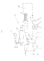
- the coagulation instrument 10 may include a knife 50 having a distal end 50 a and a proximal end 50 b disposed in the working end 30.
- the knife 50 may be pivotally mounted about a pivot axis 58 in the working end 30. So that the knife 50 at a Does not interfere with the coagulation process, the knife 50 can be sunk through a slot 33a in the first coagulation plate 33 in the first jaw part 31 so that it no longer protrudes into the space between the first coagulation plate 33 and the second Koagulationsplatte 34.
- the knife 50 can also be retractable in the movable second jaw part 32. In a cutting operation, the knife 50 is pivoted about the pivot axis 58. So that in particular a cutting is possible even when the jaw part is closed, the second coagulation plate 34 has a slot 34a, into which the knife 50 can penetrate during cutting.
- the knife 50 is interchangeably disposed in the working end 30, in particular such that it can be removed through the jaw member from the distal end of the coagulation instrument 10, in particular without the coagulation instrument 10 having to be completely disassembled or the knife 50 through the shaft tube 20 to the proximal End must be removed.
- the knife is arranged with its proximal end 50b in a blade receptacle 54, which is arranged pivotably about the pivot axis 58.
- the knife 50 can be inserted into the knife holder 54 and locked there, in particular latched.
- the blade receptacle 54 may have a ball head 52, which engages in a bore 56 of the blade 50 latching.
- the blade holder 54 is pivotally connected about the pivot axis 58 with an actuating rod 60, which is guided by the shaft tube 20 and at the proximal end 20 b of the shaft tube 20 by means of a trigger 70 is actuated.
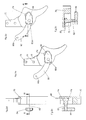
- the trigger 70 is pivotally mounted in particular on a pivot axis 72 on the shaft tube 20 or, as in the FIG. 3a illustrated, arranged on the fixed first handle portion 41.
- the pivotal connection between the trigger 70 and the actuating rod 60 via the pivotal connection 73. If the trigger 70 is pivoted about the pivot axis 72, the actuating rod 60 is moved in the axial direction in the shaft tube 20 forward or back and about the blade 50 is pivoted about the pivot axis 58 to trigger a cutting operation.
- the trigger 70 is not accidentally pivoted, a safety device can be provided which blocks the movement of the trigger 70 about the pivot axis 72.
- the trigger 70 may have a T-shaped groove 74, which is in particular curved.
- a spring 80 is guided displaceably arranged, which is designed in particular as a leaf spring.
- the spring 80 has a first end 80a and a second end 80b, the second end 80b being fixed to a stationary element of the coagulation instrument 10, for example the first grip part 41.
- the second end 80b is displaceable upon movement of the trigger 70 in the groove 74.
- a locking pin 82 is arranged, which is guided through the groove 74 on the outside of the trigger 70.
- a push button 84 may be arranged.
- the T-shaped groove 74 has a latching bore 75, in which the latching bolt 82 engages in the locked position. A displacement of the locking bolt 82 along the groove 74 is not possible, so that the movement of the trigger 70 is blocked about the pivot axis 72. If the locking pin 82 is pressed against the spring force of the leaf spring-like spring 80 in the groove 74, the locking pin 82 comes out of engagement with the locking bore 75 (see FIGS. 2c and 2e ), so that a displacement of the locking bolt 82 along the groove 74 is possible. Thus, the trigger 70 can be pivoted about the pivot axis 72 to trigger a cutting operation with the knife 50.
- the trigger 70 is spring-loaded such that it is transferred in not loaded by a user state by the force of the spring in the starting position, in which the knife 50 is recessed in the first jaw member 31 and the safety device is engaged.
- a tubular arrangement 110 may be arranged in the shaft tube 20 with, for example, four tubes 112 arranged parallel to one another (cf. FIG. 5 ), wherein in each of the tubes 112 exactly one of the elements of the two electrical conductors, the actuating rod 32b for the second jaw part 32 and the actuating rod 60 for the knife 50 is arranged.
Abstract
Description
Die Erfindung betrifft ein bipolares Koagulationsinstrument gemäß dem Oberbegriff des Patentanspruchs 1.The invention relates to a bipolar coagulation instrument according to the preamble of patent claim 1.
Bekannt sind bipolare Koagulationsinstrumente mit einem Schaftrohr, an dessen distalem Ende ein Arbeitselement angeordnet ist, welches zwei gegeneinander verschwenkbare Maulteile mit jeweils einer Koagulationsplatte sowie ein bewegbares Messer aufweist. Die Maulteile sind mittels zweier am proximalen Ende des Schaftrohrs angeordneten, gegeneinander verschwenkbaren Griffteile gegeneinander verschwenkbar. Zusätzlich ist am proximalen Ende des Schaftrohrs ein Abzug angeordnet, mittels welchem das Messer bewegbar ist. Ein derartiges Instrument ermöglicht ein Koagulieren sowie ein anschließendes Schneiden.Bipolar coagulation instruments are known with a shaft tube, at the distal end of a working element is arranged, which has two mutually pivotable jaws, each with a coagulation plate and a movable knife. The jaw parts are mutually pivotable by means of two arranged at the proximal end of the shaft tube, mutually pivotable handle parts. In addition, a trigger is arranged at the proximal end of the shaft tube, by means of which the knife is movable. Such an instrument allows for coagulation and subsequent cutting.
Die Aufgabe der Erfindung besteht darin, ein bekanntes bipolares Koagulationsinstrument weiterzubilden, insbesondere derart, dass es eine längere Lebensdauer aufweist oder sicherer zu handhaben ist.The object of the invention is to develop a known bipolar Koagulationsinstrument, in particular such that it has a longer life or safer to handle.
Die Aufgabe der Erfindung wird gelöst durch ein bipolares Koagulationsinstrument mit den Merkmalen des Patentanspruchs 1.The object of the invention is achieved by a bipolar coagulation instrument having the features of patent claim 1.
Vorteilhafte Ausgestaltungen und Weiterbildungen der Erfindung sind in den abhängigen Ansprüchen angegeben.Advantageous embodiments and further developments of the invention are specified in the dependent claims.
Das erfindungsgemäße bipolare Koagulationsinstrument mit einem Schaftrohr, mit einem am distalen Ende des Schaftrohrs angeordneten Arbeitselement, welches zwei gegeneinander mittels zweier am proximalen Ende des Schaftrohrs angeordneter, gegeneinander verschwenkbarer Griffteile verschwenkbare Maulteile, welche jeweils eine Koagulationsplatte aufweisen, und ein mittels eines am proximalen Ende des Schaftrohrs angeordneten Abzugs bewegbares Messer aufweist, zeichnet sich dadurch aus, dass das Messer auswechselbar ist. Gerade das Messer verschleißt bei Benutzung des bipolaren Koagulationsinstruments schnell und ist schwer zu reinigen. Ein auswechselbares Messer, wobei lediglich das im Arbeitselement angeordnete Messer ohne die im Schaftrohr angeordnete Betätigungsmechanik ausgewechselt wird, weist den Vorteil auf, dass ein Verschleißteil kostengünstig ausgetauscht werden kann, was die Lebensdauer und Benutzungsmöglichkeit des bipolaren Koagulationsinstruments verbessert.The bipolar coagulation instrument according to the invention with a shaft tube, with a working element arranged at the distal end of the shaft tube, which has two jaw parts which can be pivoted against one another by means of two grip parts arranged at the proximal end of the shaft tube and pivotable relative to one another. which each have a coagulation plate, and a movable means of a arranged at the proximal end of the shaft tube trigger knife, characterized in that the knife is interchangeable. Especially the knife wears quickly when using the bipolar coagulation instrument and is difficult to clean. An interchangeable knife, wherein only the blade arranged in the working element is replaced without the actuating mechanism arranged in the shaft tube, has the advantage that a wearing part can be exchanged cost-effectively, which improves the service life and possible use of the bipolar coagulation instrument.
Eine besonders bevorzugte Ausführungsform der Erfindung sieht vor, dass das Messer vom distalen Ende her auswechselbar ist. Dies vereinfacht die Handhabe des Instruments, da im Gegensatz zu bekannten Koagulationsinstrumenten, bei welchen das Messer einschließlich der Betätigungsmechanik vom proximalen Ende des Schaftrohres her aus dem Schaftrohr herausgezogen und vollständig ausgetauscht werden muss, ein schnelleres und einfacheres sowie kostengünstigeres Austauschen möglich ist.A particularly preferred embodiment of the invention provides that the knife is replaceable from the distal end. This simplifies the handle of the instrument, as in contrast to known Koagulationsinstrumenten in which the knife including the actuating mechanism from the proximal end of the shaft tube forth pulled out of the shaft tube and completely replaced, a faster and easier and cheaper replacement is possible.
Eine vorteilhafte Ausführungsform der Erfindung sieht vor, dass das Messer in eine Messeraufnahme steckbar und dort auswechselbar arretierbar, vorzugsweise mittels einer Rastverbindung einrastbar, ist. Dies ermöglicht ein einfaches Befestigen des Messers sowie ein leichtes Austauschen.An advantageous embodiment of the invention provides that the knife can be plugged into a knife receptacle and there interchangeable lockable, preferably latched by means of a latching connection, is. This allows easy attachment of the knife and easy replacement.
Vorteilhafterweise weist die Rastverbindung eine Bohrung und einen in der Bohrung einrastenden Kugelkopf auf, was eine einfache Arretierung des Messers in der Messeraufnahme ermöglicht.Advantageously, the locking connection has a bore and a latching in the bore ball head, which allows easy locking of the blade in the blade holder.
Vorzugsweise ist die Messeraufnahme um eine Schwenkachse schwenkbar angeordnet und über eine durch das Schaftrohr geführte Betätigungsstange mit dem Abzug verbunden. Dies ermöglicht eine einfache Betätigung des Messers.Preferably, the blade holder is pivotally mounted about a pivot axis and connected via a guided through the shaft tube actuating rod with the trigger. This allows easy operation of the knife.
Gemäß einer besonders bevorzugten Ausführungsform der Erfindung ist das Messer durch einen Schlitz in einer der Koagulationsplatten in einem Maulteil versenkbar angeordnet. Dadurch ist das Messer in dem Fall, dass gerade nicht geschnitten werden soll, sicher verwahrt, so dass ein unbeabsichtigtes Schneiden vermieden werden kann.According to a particularly preferred embodiment of the invention, the knife is arranged sunk through a slot in one of the coagulation plates in a jaw part. As a result, the knife in the event that just should not be cut, safe storage, so that accidental cutting can be avoided.
Eine vorteilhafte Ausführungsform der Erfindung sieht vor, dass der Abzug eine Sicherheitseinrichtung aufweist, um ein unbeabsichtigtes Auslösen des Abzugs, welches ein Schneiden des Messers bewirkt, vermeiden zu können.An advantageous embodiment of the invention provides that the trigger has a safety device in order to avoid accidental release of the trigger, which causes a cutting of the blade can.
Vorteilhafterweise weist die Sicherheitseinrichtung einen Rastmechanismus auf, welcher durch eine Bewegung quer zur Bewegung des Abzugs zu überwinden ist, bevor der Abzug betätigt werden kann. Durch die beiden verschiedenen Bewegungsrichtungen zur Bewegung des Abzugs einerseits und zur Lösung der Sicherheitseinrichtung andererseits wird es unwahrscheinlicher, dass der Abzug versehentlich betätigt wird.Advantageously, the safety device has a latching mechanism which is to be overcome by a movement transverse to the movement of the trigger before the trigger can be actuated. Due to the two different directions of movement for moving the trigger on the one hand and to solve the safety device on the other hand, it is less likely that the trigger is operated by mistake.
Vorteilhafterweise weist der Abzug eine kurvenförmige T-Nut auf, in welcher eine Feder, insbesondere eine kurvenförmige Blattfeder, geführt ist, an welcher ein Rastbolzen angeordnet ist, welcher in einer Position in einer Rastbohrung an der T-Nut einrastet. Vorteilhafterweise erfolgt dabei das Einrasten durch die Feder beaufschlagt, so dass ein Lösen des Rastbolzens aus der Ausnehmung gegen die Kraft der Feder erfolgt und anschließend der Abzug betätigt werden kann derart, dass die Feder, insbesondere die kurvenförmige Blattfeder, in der kurvenförmigen T-Nut verschiebbar geführt wird.Advantageously, the trigger on a curved T-groove, in which a spring, in particular a curved leaf spring is guided, on which a locking pin is arranged, which engages in a position in a locking bore on the T-groove. Advantageously, the engagement is effected by the spring, so that a release of the locking bolt from the recess takes place against the force of the spring and then the trigger can be actuated such that the Spring, in particular the curved leaf spring, is guided displaceably in the curved T-slot.
Ein weiteres erfindungsgemäßes bipolares Koagulationsinstrument mit einem Schaftrohr, mit einem am distalen Ende des Schaftrohrs angeordneten Arbeitselement, welches zwei gegeneinander mittels zweier am proximalen Ende des Schaftrohrs angeordneter, gegeneinander verschwenkbarer Griffteile verschwenkbare Maulteile, welche jeweils eine Koagulationsplatte aufweisen, aufweist, zeichnet sich dadurch aus, dass die Koagulationsplatten in den jeweiligen Maulteilen mittels einer Maulteileinlage isoliert angeordnet sind. Dadurch wird es ermöglicht, dass lediglich die isoliert angeordneten Koagulationsplatten mit Strom beaufschlagt werden, so dass eine Isolierung des Schaftrohrs entfallen kann.A further bipolar coagulation instrument according to the invention with a shaft tube, with a working element arranged at the distal end of the shaft tube, which has two jaw parts which can be pivoted relative to one another by means of two gripping parts which are arranged at the proximal end of the shaft tube and each have a coagulation plate. the coagulation plates are arranged isolated in the respective jaw parts by means of a jaw part insert. This makes it possible that only the isolated coagulation plates are energized, so that isolation of the shaft tube can be omitted.
Vorteilhafterweise ist die Maulteileinlage schalenförmig ausgebildet, um die Koagulationsplatte abgesehen von der der anderen Koagulationsplatte zugewandten Seitenfläche der Koagulationsplatte vollständig zu umgeben.Advantageously, the jaw member insert is cupped to completely surround the coagulation plate apart from the side surface of the coagulation plate facing the other coagulation plate.
Vorzugsweise ist jede der Koagulationsplatten über einen isolierten elektrischen Leiter mit einem am proximalen Ende des Schaftrohrs angeordneten Stromanschluss verbunden, wodurch auf einfache Art und Weise die Koagulationsplatten mit Strom beaufschlagt werden können, ohne dass zusätzliche Maßnahmen zur Isolation an dem Schaftrohr vonnöten sind.Preferably, each of the coagulation plates is connected via an insulated electrical conductor to a power connection arranged at the proximal end of the shaft tube, whereby current can be applied to the coagulation plates in a simple manner, without the need for additional measures for isolation on the shaft tube.
Vorteilhafter Weise ist eine Verriegelungsvorrichtung für das Maulteil vorgesehen, welche die Maulteile in einer Position gegeneinander arretiert, sodass eine Verschwenkung der Maulteile gegeneinander verhindert wird. Dies ermöglicht das Einklemmen von Gewebe zwischen den beiden Maulteilen zur Koagulation und zum anschließenden Schneiden.Advantageously, a locking device is provided for the jaw part, which locks the jaw parts in a position against each other, so that a pivoting of the jaws against each other is prevented. This allows pinching tissue between the two jaws for coagulation and subsequent cutting.
Eine bevorzugte Ausführungsform der Erfindung sieht vor, dass die Verriegelungsvorrichtung ein Sperrelement, insbesondere in Form einer Blattfeder, mit einem Rasthaken aufweist, welches an dem Schaftrohr oder einem starr mit dem Schaftrohr verbundenen Element angeordnet ist, wobei der Rasthaken in einen Rastvorsprung eingreift, welcher an dem relativ zum Schaftrohr verschwenkbaren Griffteil oder einem mit dem relativ zum Schaftrohr verschwenkbaren Griffteil verbundenen Element, wie beispielsweise einer Zugstange für das verschwenkbare Maulteil, angeordnet ist. Dies ermöglicht einen besonders kompakten Aufbau der Verriegelungsvorrichtung, welche insbesondere in das Schaftrohr platzsparend integriert werden kann.A preferred embodiment of the invention provides that the locking device has a locking element, in particular in the form of a leaf spring, with a latching hook, which is arranged on the shaft tube or a rigidly connected to the shaft tube element, wherein the latching hook engages in a latching projection which on the pivotable relative to the shaft tube handle part or a connected to the pivotable relative to the shaft tube handle member, such as a pull rod for the pivotable jaw part, is arranged. This allows a particularly compact design of the locking device, which can be integrated to save space, especially in the shaft tube.
Die Erfindung wird anhand der nachfolgenden Figuren ausführlich erläutert. Es zeigen:
- Figur 1
- eine perspektivische Ansicht eines Ausführungsbeispiels eines erfindungsgemäßen bipolaren Koagulationsinstruments,
- Figur 2a
- den Abzug mit Sicherheitseinrichtung des Koagulationsinstruments gemäß
Figur 1 , - Figur 2b
- eine Seitenansicht des Abzugs gemäß
Figur 2a , - Figur 2c
- einen Schnitt entlang der Linie A-A in
Figur 2b , - Figur 2d
- eine Draufsicht auf den Abzug gemäß
Figur 2a , - Figur 2e
- einen Schnitt entlang der Linie B-B in
Figur 2d , - Figur 3a
- eine teilweise Explosionsdarstellung der Verriegelungsvorrichtung des Koagulationsinstruments gemäß
Figur 1 , - Figur 3b
- eine Explosionsdarstellung der Verriegelungsvorrichtung gemäß
Figur 3a , - Figur 3c
- eine perspektivische Ansicht der Darstellung gemäß
Figur 3a , - Figur 3d
- einen schematischen Längsschnitt durch die Verriegelungsvorrichtung gemäß
Figur 3a , - Figur 4a
- eine perspektivische Ansicht des Arbeitsendes des Koagulationsinstruments gemäß
Figur 1 , - Figur 4b
- eine Seitenansicht des Arbeitsendes des Koagulationsinstruments gemäß
Figur 1 , - Figur 4c
- eine Draufsicht auf das Arbeitsende gemäß
Figur 4b , - Figur 4d
- einen Schnitt entlang der Linie A-A in
Figur 4c , - Figur 4e
- einen Schnitt entlang der Linie B-B in
Figur 4c , - Figur 4f
- einen Schnitt entlang der Linie C-C in
Figur 4c und - Figur 5
- eine perspektivische Darstellung der in dem Schaftrohr angeordneten Durchführungsanordnung.
- FIG. 1
- a perspective view of an embodiment of a bipolar coagulation instrument according to the invention,
- FIG. 2a
- the trigger with safety device of the coagulation instrument according to
FIG. 1 . - FIG. 2b
- a side view of the trigger according to
FIG. 2a . - Figure 2c
- a section along the line AA in
FIG. 2b . - Figure 2d
- a plan view of the trigger according to
FIG. 2a . - FIG. 2e
- a section along the line BB in
Figure 2d . - FIG. 3a
- a partially exploded view of the locking device of the coagulation according to
FIG. 1 . - FIG. 3b
- an exploded view of the locking device according to
FIG. 3a . - Figure 3c
- a perspective view of the illustration according to
FIG. 3a . - 3d figure
- a schematic longitudinal section through the locking device according to
FIG. 3a . - FIG. 4a
- a perspective view of the working end of the coagulation according to
FIG. 1 . - FIG. 4b
- a side view of the working end of the coagulation instrument according to
FIG. 1 . - Figure 4c
- a plan view of the working end according to
FIG. 4b . - FIG. 4d
- a section along the line AA in
Figure 4c . - Figure 4e
- a section along the line BB in
Figure 4c . - FIG. 4f
- a section along the line CC in
Figure 4c and - FIG. 5
- a perspective view of the in the Shaft tube arranged feedthrough arrangement.
Das Koagulationsinstrument 10 weist zwei gegeneinander verschwenkbare Griffteile 41, 42 auf. Dabei kann das erste Griffteil 41 starr mit dem Schaftrohr 20 verbunden sein, während das zweite Griffteil 42 um eine Schwenkachse 44 gegen das erste Griffteil 41 schwenkbar gelagert angeordnet ist. Das zweite Griffteil 42 ist gelenkig mit dem proximalen Ende einer Betätigungsstange 32b verbunden, welche durch das Schaftrohr 20 geführt ist und am distalen Ende die Schwenkachse 32a bildend mit dem zweiten Maulteil 32 verbunden ist. Bei Verschwenken des zweiten Griffteils 42 kann somit eine Zug- oder Schubbewegung auf die Betätigungsstange 32b ausgeübt werden, welche bewirkt, dass das zweite Maulteil 32 um die Schwenkachse 32a verschwenkt wird und dabei die beiden Maulteile 31, 32 derart gegeneinander verschwenkt werden, dass das dadurch gebildete Maul geöffnet oder geschlossen werden kann.The
Eine optional vorhandene Verriegelungsvorrichtung 100 für die Schwenkbewegung des zweiten Maulteils 32 ist in den
Wird das zweite Griffteil 42 derart verschwenkt, dass das zweite Maulteil 32 auf das erste Maulteil 31 zugeschwenkt wird, wird das Maul geschlossen und zwischen den beiden Maulteilen 31, 32 liegendes Gewebe in das Maulteil eingespannt. Dabei rastet der Rasthaken 102 an dem Rastvorsprung 103 ein. Bei geschlossenem Maulteil kann koaguliert werden, indem die beiden Koagulationsplatten 33, 34 mit Strom beaufschlagt werden. Nach erfolgter Koagulation kann ein optisches oder akustisches Signal abgegeben werden, um darauf hinzuweisen, dass der Koagulationsvorgang abgeschlossen wurde. Anschließend kann ein Schneidvorgang erfolgen, welcher nachfolgend detaillierter beschrieben wird. Soll das Maulteil wieder geöffnet werden, muss die Rastung zwischen dem Rasthaken 102 und dem Rastvorsprung 103 mit erhöhtem Druck über die Spannzange 106 zum Umlauf gebracht werden und insbesondere der Rasthaken 102 außer Eingriff mit dem Rastvorsprung 103 gebracht werden. Durch den erhöhten Druck auf die Spannzange 106 gibt die Spannzange 106 in axialer Richtung so lange nach, bis die Rastverbindung zwischen dem Rasthaken 102 und dem Rastvorsprung 103 gelöst wird. Das Maul kann nun wieder geöffnet werden.If the
In einer Ausführungsform ist das zweite Griffteil 42 derart mit einem Federelement 90 beaufschlagt, welches beispielsweise zwischen dem zweiten Griffteil 42 und dem distalen Ende 20a des Schaftrohrs 20 angeordnet ist, dass das Federelement 90, sofern eine Öffnung des Mauls nicht durch die Verriegelungsvorrichtung 100 verhindert ist, durch das Federelement 90 beaufschlagt in vom Benutzer unbelastetem Zustand automatisiert erfolgt.In one embodiment, the
Das Koagulationsinstrument 10 kann ein Messer 50 mit einem distalen Ende 50a und einem proximalen Ende 50b aufweisen, welches in dem Arbeitsende 30 angeordnet ist. Das Messer 50 kann um eine Schwenkachse 58 schwenkbar gelagert in dem Arbeitsende 30 angeordnet sein. Damit das Messer 50 bei einem Koagulationsvorgang nicht stört, kann das Messer 50 durch einen Schlitz 33a in der ersten Koagulationsplatte 33 in das erste Maulteil 31 derart versenkt werden, dass es nicht mehr in den Zwischenraum zwischen der ersten Koagulationsplatte 33 und der zweiten Koagulationsplatte 34 hineinragt. Alternativ kann das Messer 50 auch in dem beweglichen zweiten Maulteil 32 versenkbar sein. Bei einem Schneidvorgang wird das Messer 50 um die Schwenkachse 58 geschwenkt. Damit insbesondere ein Durchschneiden auch bei geschlossenem Maulteil möglich ist, weist die zweite Koagulationsplatte 34 einen Schlitz 34a auf, in den das Messer 50 beim Durchschneiden eindringen kann.The
Das Messer 50 ist auswechselbar in dem Arbeitsende 30 angeordnet, insbesondere derart, dass es durch das Maulteil vom distalen Ende des Koagulationsinstruments 10 her entnommen werden kann, insbesondere ohne dass das Koagulationsinstrument 10 vollständig demontiert werden muss oder das Messer 50 durch das Schaftrohr 20 zum proximalen Ende hin entnommen werden muss. Dazu ist das Messer mit seinem proximalen Ende 50b in einer Messeraufnahme 54 angeordnet, welche um die Schwenkachse 58 schwenkbar angeordnet ist. Das Messer 50 ist in die Messeraufnahme 54 einsteckbar und dort arretierbar, insbesondere verrastbar. Dazu kann die Messeraufnahme 54 einen Kugelkopf 52 aufweisen, welcher in eine Bohrung 56 des Messers 50 rastend eingreift. Die Messeraufnahme 54 ist um die Schwenkachse 58 schwenkbar mit einer Betätigungsstange 60 verbunden, welche durch das Schaftrohr 20 geführt ist und am proximalen Ende 20b des Schaftrohrs 20 mittels eines Abzugs 70 betätigbar ist. Der Abzug 70 ist dazu insbesondere über eine Schwenkachse 72 schwenkbar gelagert an dem Schaftrohr 20 oder, wie in der
Damit der Abzug 70 nicht versehentlich verschwenkt wird, kann eine Sicherheitseinrichtung vorgesehen werden, welche die Bewegung des Abzugs 70 um die Schwenkachse 72 blockiert. Dazu kann der Abzug 70 eine T-förmige Nut 74 aufweisen, welche insbesondere gekrümmt ausgebildet ist. In der Nut 74 ist eine Feder 80 geführt verschiebbar angeordnet, welche insbesondere als Blattfeder ausgebildet ist. Die Feder 80 weist ein erstes Ende 80a und ein zweites Ende 80b auf, wobei das zweite Ende 80b an einem feststehenden Element des Koagulationsinstruments 10, beispielsweise dem ersten Griffteil 41, fixiert ist. Das zweite Ende 80b ist bei Bewegung des Abzugs 70 in der Nut 74 verschiebbar. An dem zweiten Ende 80b der Feder 80 ist ein Rastbolzen 82 angeordnet, welcher durch die Nut 74 auf die Außenseite des Abzugs 70 geführt ist. An dem freien Ende des Rastbolzens 82 kann ein Druckknopf 84 angeordnet sein.Thus, the
Die T-förmige Nut 74 weist eine Rastbohrung 75 auf, in welcher der Rastbolzen 82 in der verriegelten Position einrastet. Ein Verschieben des Rastbolzens 82 entlang der Nut 74 ist nicht möglich, sodass die Bewegung des Abzugs 70 um die Schwenkachse 72 blockiert ist. Wird der Rastbolzen 82 gegen die Federkraft der blattfederartigen Feder 80 in die Nut 74 eingedrückt, kommt der Rastbolzen 82 außer Eingriff mit der Rastbohrung 75 (vergleiche
Vorteilhafterweise ist auch der Abzug 70 derart federbelastet, dass er im nicht durch einen Benutzer belasteten Zustand durch die Kraft der Feder in die Ausgangsposition überführt wird, in welcher das Messer 50 in dem ersten Maulteil 31 versenkt angeordnet ist und die Sicherheitseinrichtung in Eingriff ist.Advantageously, the
Durch das Schaftrohr 20 sind zwei elektrische Leiter sowie die Betätigungsstange 60 zur Bewegung des Messers 50 und die Betätigungsstange 32b zur Bewegung des zweiten Maulteils 32 geführt. Um einen Kontakt zwischen den elektrischen Leitern und den Betätigungsstangen 60, 32b zu vermeiden und vorzugsweise eine Abschirmung der elektrischen Leiter gegeneinander zu erreichen, kann in einer Ausführungsform in dem Schaftrohr 20 eine Rohranordnung 110 mit beispielsweise vier parallel zueinander angeordneten Rohren 112 angeordnet sein (vergleiche
- 1010
- Koagulationsinstrumentcoagulation
- 2020
- Schaftrohrsteerer
- 20a20a
- distales Endedistal end
- 20b20b
- proximales Endeproximal end
- 2222
- Stromanschlusspower connection
- 2323
- Kontaktelementcontact element
- 2424
- Kontaktelementcontact element
- 3030
- Arbeitsendeend of work
- 3131
- erstes Maulteilfirst jaw part
- 3232
- zweites Maulteilsecond jaw part
- 32a32a
- Schwenkachseswivel axis
- 32b32b
- Betätigungsstangeactuating rod
- 3333
- erste Koagulationsplattefirst coagulation plate
- 33a33a
- Schlitzslot
- 3434
- zweite Koagulationsplattesecond coagulation plate
- 34a34a
- Schlitzslot
- 3535
- erste Maulteileinlagefirst jaw insert
- 3636
- zweite Maulteileinlagesecond jaw insert
- 4141
- erstes Griffteilfirst handle part
- 4242
- zweites Griffteilsecond handle part
- 4444
- Schwenkachseswivel axis
- 5050
- Messerknife
- 5252
- Kugelkopfball head
- 5454
- Messeraufnahmeknife receiver
- 5656
- Bohrungdrilling
- 5858
- Schwenkachseswivel axis
- 6060
- Betätigungsstangeactuating rod
- 7070
- Abzugdeduction
- 7272
- Schwenkachseswivel axis
- 7373
- Verbindungconnection
- 7474
- Nutgroove
- 8080
- Federfeather
- 80a80a
- erstes Endefirst end
- 80b80b
- zweites Endesecond end
- 8282
- RastbolzenIndexing plungers
- 8484
- Druckkopfprinthead
- 9090
- Federelementspring element
- 100100
- Verriegelunglock
- 101101
- Sperrelementblocking element
- 102102
- Rasthakenlatch hook
- 103103
- Rastvorsprungcatch projection
- 105105
- Hülseshell
- 106106
- Spannzangecollet
- 107107
- Kugelkopfball head
- 110110
- Rohranordnungpipe arrangement
- 112112
- Rohrpipe
Claims (15)
dadurch gekennzeichnet, dass das Messer (50) auswechselbar ist.Bipolar coagulation instrument (10) with a shaft tube (20), with a at the distal end (20a) of the shaft tube (20) arranged working element 830), which two against each other by means of two at the proximal end (20b) of the shaft tube (20) arranged, mutually pivotable Handle parts (41, 42) pivotable jaw parts (31, 32), each having a coagulation plate (33, 34), and a means of a at the proximal end (20b) of the shaft tube (20)) arranged trigger (70) movable knife (50 ) having,
characterized in that the knife (50) is replaceable.
dadurch gekennzeichnet, dass das Messer (50) vom distalen Ende her auswechselbar ist.Bipolar coagulation instrument according to claim 1,
characterized in that the knife (50) is replaceable from the distal end.
dadurch gekennzeichnet, dass das Messer (50) in eine Messeraufnahme (54) steckbar und dort auswechselbar arretierbar, vorzugsweise mittels einer Rastverbindung einrastbar, ist.Bipolar coagulation instrument according to one of the preceding claims,
characterized in that the knife (50) pluggable in a blade receptacle (54) and there interchangeable lockable, preferably latched by means of a latching connection, is.
dadurch gekennzeichnet, dass die Rastverbindung eine Bohrung (56) und einen in der Bohrung (56) einrastenden Kugelkopf (52) aufweist.Bipolar coagulation instrument according to claim 3,
characterized in that the latching connection has a bore (56) and a in the bore (56) latching ball head (52).
dadurch gekennzeichnet, dass die Messeraufnahme (54) um eine Schwenkachse (58) schwenkbar angeordnet ist und über eine durch das Schaftrohr (20) geführte Betätigungsstange (60) mit dem Abzug (70) verbunden ist.Bipolar coagulation instrument according to claim 3 or 4,
characterized in that the blade receptacle (54) about a pivot axis (58) is pivotally mounted and via a through the shaft tube (20) guided actuating rod (60) with the trigger (70) is connected.
dadurch gekennzeichnet, dass das Messer (50) um eine Schwenkachse (58) verschwenkbar angeordnet ist.Bipolar coagulation instrument according to one of the preceding claims,
characterized in that the knife (50) about a pivot axis (58) is arranged pivotably.
dadurch gekennzeichnet, dass das Messer (50) durch einen Schlitz (33a) in einer der Koagulationsplatten (33) in einem der Maulteile (31) versenkbar angeordnet ist.Bipolar coagulation instrument according to one of the preceding claims,
characterized in that the knife (50) is retractable through a slot (33a) in one of the coagulation plates (33) in one of the jaws (31).
dadurch gekennzeichnet, dass der Abzug (70) eine Sicherheitseinrichtung aufweist.Bipolar coagulation instrument according to one of the preceding claims,
characterized in that the trigger (70) has a safety device.
dadurch gekennzeichnet, dass die Sicherheitseinrichtung einen Rastmechanismus aufweist, welcher durch eine Bewegung quer zur Bewegung des Abzugs (70) zu überwinden ist, bevor der Abzug (70) betätigbar ist.Bipolar coagulation instrument according to claim 8,
characterized in that the safety device comprises a latching mechanism which is to be overcome by a movement transverse to the movement of the trigger (70) before the trigger (70) is actuated.
dadurch gekennzeichnet, dass der Abzug (70) eine kurvenförmige T-Nut (74)aufweist, in welcher eine Feder (80), insbesondere eine kurvenförmige Blattfeder geführt ist, an welcher ein Rastbolzen (82) angeordnet ist, welcher in einer Position in eine Rastbohrung (75) an der T-Nut (74) einrastet.Bipolar coagulation instrument according to claim 8 or 9,
characterized in that the trigger (70) has a curved T-slot (74) in which a spring (80), in particular a curved leaf spring is guided, on which a locking pin (82) is arranged, which in a position in one Locking hole (75) on the T-slot (74) engages.
der vorhergehenden Ansprüche, mit einem Schaftrohr (20), mit einem am distalen Ende (20a) des Schaftrohrs (20) angeordneten Arbeitselement (30), welches zwei gegeneinander mittels zweier am proximalen Ende (20b) des Schaftrohrs (20) angeordneter, gegeneinander verschwenkbarer Griffteile (41, 42) verschwenkbare Maulteile (31, 32), welche jeweils eine Koagulationsplatte (33, 34) aufweisen,
dadurch gekennzeichnet, dass die Koagulationsplatten (33, 34) in den jeweiligen Maulteilen (31, 32) mittels einer Maulteileinlage (35, 36) isoliert angeordnet sind.Bipolar coagulation instrument, especially after one
of the preceding claims, with a shaft tube (20), with a at the distal end (20a) of the shaft tube (20) arranged working element (30), which two against each other by means of two at the proximal end (20b) of the shaft tube (20) arranged, mutually pivotable Handle parts (41, 42) pivotable jaw parts (31, 32), which each have a coagulation plate (33, 34),
characterized in that the coagulation plates (33, 34) in the respective jaws (31, 32) by means of a jaw part insert (35, 36) are arranged isolated.
dadurch gekennzeichnet, dass die Maulteileinlage (35, 36) schalenförmig ausgebildet ist.Bipolar coagulation instrument according to claim 11,
characterized in that the jaw part insert (35, 36) is cup-shaped.
dadurch gekennzeichnet, dass jede der Koagulationsplatten (33, 34) über einen isolierten elektrischen Leiter mit einem am proximalen Ende (20b) des Schaftrohrs (20) angeordneten Stromanschluss (22) verbunden ist.Bipolar coagulation instrument according to claim 11 or 12,
characterized in that each of the coagulation plates (33, 34) is connected via an insulated electrical conductor to a power connection (22) arranged at the proximal end (20b) of the shaft tube (20).
dadurch gekennzeichnet, dass eine Verriegelungsvorrichtung (100) für das Maulteil vorgesehen ist.Bipolar coagulation instrument according to one of the preceding claims,
characterized in that a locking device (100) is provided for the jaw part.
dadurch gekennzeichnet, dass die Verriegelungsvorrichtung (100) ein Sperrelement (101), insbesondere in Form einer Blattfeder, mit einem Rasthaken (102) aufweist, welches an dem Schaftrohr (20) oder einem starr mit dem Schaftrohr (20) verbundenen Element angeordnet ist, wobei der Rasthaken (102) an einem Rastvorsprung (103) angreift, welcher an dem relativ zum Schaftrohr (20) verschwenkbaren Griffteil (42) oder einem mit dem relativ zum Schaftrohr (20) verschwenkbaren Griffteil (42) verbundenen Element angeordnet ist.Bipolar coagulation instrument according to one of the preceding claims,
characterized in that the locking device (100) has a blocking element (101), in particular in the form of a leaf spring, with a latching hook (102) which is arranged on the shaft tube (20) or an element rigidly connected to the shaft tube (20), wherein the latching hook (102) engages a latching projection (103) which is arranged on the relative to the shaft tube (20) pivotable handle part (42) or with the relative to the shaft tube (20) pivotable handle member (42) connected element.
Applications Claiming Priority (1)
| Application Number | Priority Date | Filing Date | Title |
|---|---|---|---|
| DE201220010938 DE202012010938U1 (en) | 2012-11-15 | 2012-11-15 | Bipolar bayonet HF instrument for coagulation and cutting with replaceable knife and safety device in the trigger |
Publications (1)
| Publication Number | Publication Date |
|---|---|
| EP2732779A1 true EP2732779A1 (en) | 2014-05-21 |
Family
ID=49641516
Family Applications (1)
| Application Number | Title | Priority Date | Filing Date |
|---|---|---|---|
| EP13193121.4A Withdrawn EP2732779A1 (en) | 2012-11-15 | 2013-11-15 | Bipolar coagulation instrument |
Country Status (2)
| Country | Link |
|---|---|
| EP (1) | EP2732779A1 (en) |
| DE (2) | DE202012010938U1 (en) |
Cited By (2)
| Publication number | Priority date | Publication date | Assignee | Title |
|---|---|---|---|---|
| EP3815642A1 (en) | 2019-10-28 | 2021-05-05 | Erbe Elektromedizin GmbH | Blade cartridge and sealing instrument |
| EP3849441A4 (en) * | 2018-09-14 | 2022-06-29 | Covidien LP | Articulating blade deployment |
Citations (5)
| Publication number | Priority date | Publication date | Assignee | Title |
|---|---|---|---|---|
| DE19637133A1 (en) * | 1995-09-12 | 1997-03-13 | Cabot Tech Corp | Container for knife assembly and process |
| US5913874A (en) * | 1997-09-25 | 1999-06-22 | Cabot Technology Corporation | Cartridge for a surgical instrument |
| EP2316366A2 (en) * | 2009-10-30 | 2011-05-04 | Tyco Healthcare Group, LP | Roll joint for a surgical instrument |
| US20120101488A1 (en) * | 2010-10-26 | 2012-04-26 | Ethicon Endo-Surgery, Inc. | Surgical instrument with magnetic clamping force |
| EP2489319A1 (en) * | 2011-02-18 | 2012-08-22 | Tyco Healthcare Group, LP | Apparatus with multiple channel selective cutting |
-
2012
- 2012-11-15 DE DE201220010938 patent/DE202012010938U1/en not_active Expired - Lifetime
-
2013
- 2013-11-15 DE DE201320012036 patent/DE202013012036U1/en not_active Expired - Lifetime
- 2013-11-15 EP EP13193121.4A patent/EP2732779A1/en not_active Withdrawn
Patent Citations (5)
| Publication number | Priority date | Publication date | Assignee | Title |
|---|---|---|---|---|
| DE19637133A1 (en) * | 1995-09-12 | 1997-03-13 | Cabot Tech Corp | Container for knife assembly and process |
| US5913874A (en) * | 1997-09-25 | 1999-06-22 | Cabot Technology Corporation | Cartridge for a surgical instrument |
| EP2316366A2 (en) * | 2009-10-30 | 2011-05-04 | Tyco Healthcare Group, LP | Roll joint for a surgical instrument |
| US20120101488A1 (en) * | 2010-10-26 | 2012-04-26 | Ethicon Endo-Surgery, Inc. | Surgical instrument with magnetic clamping force |
| EP2489319A1 (en) * | 2011-02-18 | 2012-08-22 | Tyco Healthcare Group, LP | Apparatus with multiple channel selective cutting |
Cited By (2)
| Publication number | Priority date | Publication date | Assignee | Title |
|---|---|---|---|---|
| EP3849441A4 (en) * | 2018-09-14 | 2022-06-29 | Covidien LP | Articulating blade deployment |
| EP3815642A1 (en) | 2019-10-28 | 2021-05-05 | Erbe Elektromedizin GmbH | Blade cartridge and sealing instrument |
Also Published As
| Publication number | Publication date |
|---|---|
| DE202012010938U1 (en) | 2014-02-18 |
| DE202013012036U1 (en) | 2015-03-18 |
Similar Documents
| Publication | Publication Date | Title |
|---|---|---|
| EP0692224B1 (en) | Multi-function medical instrument for endoscopic operations | |
| EP1082061B1 (en) | Handle for a medical hollow shaft instrument | |
| EP1809444B1 (en) | Device for locking a battery pack in a guide in an electric tool | |
| DE3533645C2 (en) | ||
| EP1453415B1 (en) | Endoscope | |
| DE2858032C2 (en) | Surgical stapling instrument for stapling hollow organs | |
| WO2002017808A1 (en) | Urological electrosurgical resectoscope | |
| DE2109319B2 (en) | Tool for loosening contact pins and contact sockets from the contact chambers of the insulating bodies of connectors | |
| EP2732779A1 (en) | Bipolar coagulation instrument | |
| EP1319456A1 (en) | Cable cutter | |
| DE19624811A1 (en) | Surgical suction and rinsing device | |
| WO2004075765A1 (en) | Surgical instrument | |
| EP4079240B1 (en) | Blade cartridge for a surgical instrument | |
| EP2904977B1 (en) | Surgical instrument and handle for same | |
| EP2476381A1 (en) | Dismountable surgical instrument with flat head | |
| DE102011014200B4 (en) | Lancing device with side-mounted actuator | |
| EP3815642B1 (en) | Blade cartridge and sealing instrument | |
| DE202013100819U1 (en) | scalpel holder | |
| EP3471219B1 (en) | Connector system and connector for establishing an electrical connection | |
| DE102020115087A1 (en) | Handle device for a hand machine tool | |
| EP3049143B1 (en) | Positioning device for a medical catheter | |
| DE202013102875U1 (en) | Surgical instrument | |
| CH547103A (en) | DEVICE FOR LOCKING AND CUTTING TUBULAR TUBES. | |
| EP3179931B1 (en) | Medical instrument for endoscopic surgery | |
| DE102011081344B4 (en) | coagulation |
Legal Events
| Date | Code | Title | Description |
|---|---|---|---|
| PUAI | Public reference made under article 153(3) epc to a published international application that has entered the european phase |
Free format text: ORIGINAL CODE: 0009012 |
|
| 17P | Request for examination filed |
Effective date: 20131115 |
|
| AK | Designated contracting states |
Kind code of ref document: A1 Designated state(s): AL AT BE BG CH CY CZ DE DK EE ES FI FR GB GR HR HU IE IS IT LI LT LU LV MC MK MT NL NO PL PT RO RS SE SI SK SM TR |
|
| AX | Request for extension of the european patent |
Extension state: BA ME |
|
| STAA | Information on the status of an ep patent application or granted ep patent |
Free format text: STATUS: THE APPLICATION IS DEEMED TO BE WITHDRAWN |
|
| 18D | Application deemed to be withdrawn |
Effective date: 20141122 |