EP2740431A1 - Controlled irrigated catheter ablation systems and methods thereof - Google Patents
Controlled irrigated catheter ablation systems and methods thereof Download PDFInfo
- Publication number
- EP2740431A1 EP2740431A1 EP14157953.2A EP14157953A EP2740431A1 EP 2740431 A1 EP2740431 A1 EP 2740431A1 EP 14157953 A EP14157953 A EP 14157953A EP 2740431 A1 EP2740431 A1 EP 2740431A1
- Authority
- EP
- European Patent Office
- Prior art keywords
- electrode
- irrigation
- ablation
- fluid
- flow
- Prior art date
- Legal status (The legal status is an assumption and is not a legal conclusion. Google has not performed a legal analysis and makes no representation as to the accuracy of the status listed.)
- Granted
Links
- 238000013153 catheter ablation Methods 0.000 title claims abstract description 22
- 238000000034 method Methods 0.000 title abstract description 60
- 230000002262 irrigation Effects 0.000 claims abstract description 149
- 238000003973 irrigation Methods 0.000 claims abstract description 149
- 239000012530 fluid Substances 0.000 claims abstract description 112
- 238000002679 ablation Methods 0.000 claims abstract description 106
- 238000009529 body temperature measurement Methods 0.000 claims description 29
- 230000007246 mechanism Effects 0.000 claims description 18
- 238000004891 communication Methods 0.000 claims description 14
- 238000012423 maintenance Methods 0.000 claims description 10
- FAPWRFPIFSIZLT-UHFFFAOYSA-M Sodium chloride Chemical compound [Na+].[Cl-] FAPWRFPIFSIZLT-UHFFFAOYSA-M 0.000 claims description 8
- 239000011780 sodium chloride Substances 0.000 claims description 6
- 230000006903 response to temperature Effects 0.000 claims description 3
- 230000004044 response Effects 0.000 abstract description 14
- 230000003111 delayed effect Effects 0.000 abstract description 13
- 230000001105 regulatory effect Effects 0.000 abstract description 8
- 230000023555 blood coagulation Effects 0.000 abstract description 4
- 238000001816 cooling Methods 0.000 abstract description 3
- 230000015271 coagulation Effects 0.000 abstract description 2
- 238000005345 coagulation Methods 0.000 abstract description 2
- 230000000712 assembly Effects 0.000 description 8
- 238000000429 assembly Methods 0.000 description 8
- 230000008878 coupling Effects 0.000 description 5
- 238000010168 coupling process Methods 0.000 description 5
- 238000005859 coupling reaction Methods 0.000 description 5
- 238000013461 design Methods 0.000 description 5
- 238000007674 radiofrequency ablation Methods 0.000 description 5
- 230000003247 decreasing effect Effects 0.000 description 4
- 239000004020 conductor Substances 0.000 description 3
- 230000003902 lesion Effects 0.000 description 3
- 239000000463 material Substances 0.000 description 3
- KDLHZDBZIXYQEI-UHFFFAOYSA-N Palladium Chemical compound [Pd] KDLHZDBZIXYQEI-UHFFFAOYSA-N 0.000 description 2
- 230000033228 biological regulation Effects 0.000 description 2
- 230000015572 biosynthetic process Effects 0.000 description 2
- 239000012809 cooling fluid Substances 0.000 description 2
- 238000005259 measurement Methods 0.000 description 2
- 239000000203 mixture Substances 0.000 description 2
- 238000012544 monitoring process Methods 0.000 description 2
- BASFCYQUMIYNBI-UHFFFAOYSA-N platinum Chemical compound [Pt] BASFCYQUMIYNBI-UHFFFAOYSA-N 0.000 description 2
- 230000008569 process Effects 0.000 description 2
- 230000001225 therapeutic effect Effects 0.000 description 2
- 238000011282 treatment Methods 0.000 description 2
- 208000007536 Thrombosis Diseases 0.000 description 1
- 239000000853 adhesive Substances 0.000 description 1
- 230000001070 adhesive effect Effects 0.000 description 1
- 230000004075 alteration Effects 0.000 description 1
- 230000005540 biological transmission Effects 0.000 description 1
- 230000001276 controlling effect Effects 0.000 description 1
- 238000007796 conventional method Methods 0.000 description 1
- 238000003745 diagnosis Methods 0.000 description 1
- -1 e.g. Substances 0.000 description 1
- 238000002001 electrophysiology Methods 0.000 description 1
- 230000007831 electrophysiology Effects 0.000 description 1
- PCHJSUWPFVWCPO-UHFFFAOYSA-N gold Chemical compound [Au] PCHJSUWPFVWCPO-UHFFFAOYSA-N 0.000 description 1
- 229910052737 gold Inorganic materials 0.000 description 1
- 239000010931 gold Substances 0.000 description 1
- 229910052741 iridium Inorganic materials 0.000 description 1
- GKOZUEZYRPOHIO-UHFFFAOYSA-N iridium atom Chemical compound [Ir] GKOZUEZYRPOHIO-UHFFFAOYSA-N 0.000 description 1
- WABPQHHGFIMREM-UHFFFAOYSA-N lead(0) Chemical compound [Pb] WABPQHHGFIMREM-UHFFFAOYSA-N 0.000 description 1
- 238000013507 mapping Methods 0.000 description 1
- 229910052763 palladium Inorganic materials 0.000 description 1
- 230000000737 periodic effect Effects 0.000 description 1
- 229910052697 platinum Inorganic materials 0.000 description 1
- 230000004845 protein aggregation Effects 0.000 description 1
- 238000012552 review Methods 0.000 description 1
- 230000000630 rising effect Effects 0.000 description 1
- 238000005096 rolling process Methods 0.000 description 1
- 239000010935 stainless steel Substances 0.000 description 1
- 229910001220 stainless steel Inorganic materials 0.000 description 1
- 230000000451 tissue damage Effects 0.000 description 1
- 231100000827 tissue damage Toxicity 0.000 description 1
- 210000005166 vasculature Anatomy 0.000 description 1
- 238000012800 visualization Methods 0.000 description 1
Images


Classifications
-
- A—HUMAN NECESSITIES
- A61—MEDICAL OR VETERINARY SCIENCE; HYGIENE
- A61B—DIAGNOSIS; SURGERY; IDENTIFICATION
- A61B18/00—Surgical instruments, devices or methods for transferring non-mechanical forms of energy to or from the body
- A61B18/04—Surgical instruments, devices or methods for transferring non-mechanical forms of energy to or from the body by heating
- A61B18/12—Surgical instruments, devices or methods for transferring non-mechanical forms of energy to or from the body by heating by passing a current through the tissue to be heated, e.g. high-frequency current
- A61B18/14—Probes or electrodes therefor
- A61B18/1492—Probes or electrodes therefor having a flexible, catheter-like structure, e.g. for heart ablation
-
- A—HUMAN NECESSITIES
- A61—MEDICAL OR VETERINARY SCIENCE; HYGIENE
- A61B—DIAGNOSIS; SURGERY; IDENTIFICATION
- A61B17/00—Surgical instruments, devices or methods, e.g. tourniquets
- A61B2017/00017—Electrical control of surgical instruments
- A61B2017/00022—Sensing or detecting at the treatment site
- A61B2017/00084—Temperature
-
- A—HUMAN NECESSITIES
- A61—MEDICAL OR VETERINARY SCIENCE; HYGIENE
- A61B—DIAGNOSIS; SURGERY; IDENTIFICATION
- A61B18/00—Surgical instruments, devices or methods for transferring non-mechanical forms of energy to or from the body
- A61B2018/00005—Cooling or heating of the probe or tissue immediately surrounding the probe
- A61B2018/00011—Cooling or heating of the probe or tissue immediately surrounding the probe with fluids
- A61B2018/00029—Cooling or heating of the probe or tissue immediately surrounding the probe with fluids open
-
- A—HUMAN NECESSITIES
- A61—MEDICAL OR VETERINARY SCIENCE; HYGIENE
- A61B—DIAGNOSIS; SURGERY; IDENTIFICATION
- A61B2218/00—Details of surgical instruments, devices or methods for transferring non-mechanical forms of energy to or from the body
- A61B2218/001—Details of surgical instruments, devices or methods for transferring non-mechanical forms of energy to or from the body having means for irrigation and/or aspiration of substances to and/or from the surgical site
- A61B2218/002—Irrigation
Definitions
- the present invention relates to irrigated catheter assembly systems and methods for ablating tissue using controlled irrigation flow.
- the present invention further relates to open irrigated catheter ablation systems having irrigation fluid flow that may be regulated in connection with a predetermined temperature threshold.
- Electrophysiology catheters are used for an ever-increasing number of procedures.
- catheters are used for diagnostic, therapeutic, and ablative procedures, to name just a few procedures.
- a catheter is manipulated through the patient's vasculature to an intended site, for example, a site within the patient's heart.
- the catheter commonly carries one or more electrodes, which may be used for ablation, diagnosis, and/or other treatments.
- RF ablation is accomplished by transmission of radiofrequency energy to a desired target area through an electrode assembly to ablate tissue at a target site.
- RF ablation may generate significant heat, which if not controlled could result in tissue damage, such as steam pop, tissue charring, and the like, it is often desirable to include a mechanism to irrigate the target area and the device with biocompatible fluids, such as saline solution.
- biocompatible fluids such as saline solution.
- the use of fluid irrigated ablation catheters can also prevent the formation of soft thrombus and/or blood coagulation.
- Closed ablation catheters can circulate a cooling fluid within the inner cavity of the ablation electrode.
- Open ablation catheters can deliver the cooling fluid through open outlets or openings on the surface of the electrode.
- Open ablation catheters use the inner cavity of the electrode, or distal member, as a manifold to distribute saline solution (or other irrigation fluids known to those skilled in the art) to one or more passageways that lead to openings/outlets provided on the surface of the electrode.
- the saline thus flows directly through the outlets of the passageways onto or about the distal electrode member. This direct flow through the distal electrode tip lowers the temperature of the distal tip during operation, which may make accurate monitoring and control of the ablation process somewhat more challenging.
- open irrigated ablation catheters may improve the safety of RF catheter ablation by preventing protein aggregation and blood coagulation through the dissipation of heat by providing fluid to the site during the ablation procedure
- direct contacting fluid irrigation has the tendency to cool the electrode temperature dramatically during ablation procedures.
- the irrigation fluid flow ultimately cuts off the electrode temperature from rising, which may result in increased (and possibly more than desirable) ablation in a target area. As such, it can be desirable to control and more accurately monitor the temperature of an electrode performing ablation.
- the present invention is directed to improved open irrigated catheter ablation systems and methods used in connection with open irrigated catheter systems.
- systems and related methods are provided that can control irrigation fluid flow and obtain an effective temperature response with respect to an ablation procedure.
- Embodiments of the present invention provide an irrigated catheter ablation system having controlled irrigation fluid flow directed at target areas, for example, where coagulation is more likely to occur so as to minimize blood coagulation and associated problems.
- the irrigated fluid flow may be regulated in connection with a predetermined temperature threshold to improve or better optimize cooling and ablation properties associated with the system.
- the present invention provides an ablation system having an open irrigated ablation electrode coupled to or connected with a catheter shaft forming an open irrigated catheter assembly in connection with a fluid source, an energy source, and a temperature control mechanism for regulating irrigation fluid flow within the catheter shaft assembly.
- the fluid source preferably includes a saline pump.
- the irrigation temperature control mechanism preferably includes a controller.
- the present invention further discloses an ablation system having an open irrigated ablation catheter assembly including an open irrigated ablation electrode coupled to or connected to a catheter shaft forming the open irrigated catheter assembly in connection with a fluid source, an energy source, such as, for example, radio frequency (RF) generator, and a processor for regulating the temperature control of the electrode performing the ablation.
- RF radio frequency
- the present invention provides a method of controlling the irrigation of biological tissue.
- the method includes the steps of providing an irrigated catheter ablation system including an irrigated ablation catheter assembly, a fluid source connected to the catheter assembly, an energy source connected to the catheter assembly; and an irrigation temperature control mechanism in communication with the fluid source and energy source; presetting a temperature threshold for the system that regulates irrigation fluid flow from the passageway of the catheter assembly; positioning the irrigated electrode of the irrigated ablation catheter assembly at a target location; applying energy from the energy source to the target location through the irrigated electrode; collecting temperature measurements from a thermal sensor disposed within the irrigated electrode; irrigating the ablation electrode forming an irrigation flow through the passageway of the electrode; and completing the application of energy to the target location to form an ablation lesion.
- the invention further contemplates alternate methods for irrigating biological tissue, including a delayed irrigation method and an intermitted irrigation method.
- the delayed irrigation method involves collecting temperature measurements of the open irrigation electrode until the collected temperature measurements of the electrode reach a predetermined upper temperature threshold. Once the upper temperature threshold is met, the irrigation fluid flow from the passageways of the open irrigation electrode increases from a maintenance flow rate to an amplified irrigation flow rate. The increased irrigation flow continues until the ablation is completed.
- the intermitted method further includes collecting temperature measurements of the electrode until the temperature measurements of the electrode reach a predetermined lower temperature threshold. Once the electrode temperature measurements reach the lower threshold level, the irrigation flow is reduced to the maintenance flow level through the passageway of the electrode.
- the irrigation flow is reduced, temperature measurements continue to be collected from a thermal sensor disposed within the irrigated electrode until the temperature measurements once again return to the predetermined upper temperature threshold.
- the irrigation fluid flow is then increased again through the passageway of the electrode therein creating an intermitted irrigation cycle. Accordingly, the irrigation flow is reduced periodically during the intermitted irrigation cycle in response to the temperature.
- the intermitted irrigation cycle is continued until the ablation is complete.
- the intermitted irrigation method further provides that the irrigation may be turned off periodically during the ablation procedure to check the temperature response of the electrode until the ablation is completely.
- the instant invention relates to irrigated catheter ablation systems and to methods of using irrigated catheter ablation systems.
- similar aspects among the various embodiments described herein will generally be referred to by the same reference number. As will be appreciated, however, the structure of the various aspects may differ among various embodiments.
- Open irrigated catheter ablation systems of the present invention include an irrigated ablation catheter assembly 10, as generally shown in Figure 1 .
- the illustrated irrigated ablation catheter assembly 10 includes an ablation electrode 12. While embodiments of the invention disclosed herein may describe RF ablation catheter assemblies and related systems, the invention is not so limited, and the invention may include or involve other types of ablation electrodes and assemblies in which the temperature of the device and a targeted tissue area may be factors during the procedure.
- Figures 2 and 3 discussed in further detail below, illustrate specific open irrigated ablation electrodes 10 according to alternate embodiments associated with the present invention.
- Figures 4 and 5 discussed in further detail below, illustrate catheter ablation systems embodying features associated with the present invention.
- Embodiments of open irrigated catheter ablation systems in accordance with the present invention include an open irrigated catheter assembly 10 having an open irrigated electrode 12 configured to control the flow of irrigation fluid to an ablation site.
- the present invention encompasses irrigated catheter assembly systems that control and regulate the irrigation fluid flow to an ablation site, for example, to improve or optimized ablation on a tissue while irrigating the surface of the tissue.
- the system may be configured and/or regulated to provide either intermitted irrigation fluid flow throughout the ablation procedure or a delayed onset of irrigation to ensure good physical contact of electrode 12 with the ablation site.
- temperature feedback may be used in combination with responsive irrigation flow to improve or optimize tissue ablation when using convention open irrigated ablation catheters to perform an ablation procedure or technique on biological tissue.
- conventional irrigation catheters include, but are not limited to, those such as IBI TherapTM Cool PathTM Ablation Catheter available from Irvine Biomedical, Inc.
- one embodiment of the present invention provides a system and related method for performing RF ablation that includes the delayed onset of the irrigation fluid flow to electrode 12.
- the onset of therapeutic irrigation fluid flow may be controllably delayed until electrode 12 reaches a predetermined temperature threshold, such as, without limitation, about 65 degrees Celsius.
- a predetermined temperature threshold such as, without limitation, about 65 degrees Celsius.
- the irrigation fluid flow can be started to provide cooling to the electrode.
- the delayed onset of the irrigation flow better ensures that an accurate temperature reading of the electrode may be obtained during the initial ablation procedure, which further helps ensure improved physical contact between electrode 12 and a targeted site (e.g., targeted tissue).
- the temperature threshold is not met upon the application of the ablation energy or shortly thereafter, electrode 12 may need to be repositioned to ensure sufficient or proper physical contact with targeted tissue. Since the temperature threshold is generally set below an associated safety limit, e.g., about 65 degrees C, heat related coagulum that is present can be eliminated in connection with the ablation.
- An alternate embodiment of the present invention provides a system and related method for performing ablation, such as RF ablation, that includes intermitted fluid irrigation flow such that irrigation fluid may be regulated ( i.e., increased and decreased) in response to the temperature of electrode 12. More particularly, the intermitted fluid irrigation flow may be controlled by a predetermined temperature threshold, such as, for example, about 65 degrees. Accordingly, the irrigation fluid flow may be increased when the electrodes reaches about 65 degrees and is then decreased once a reduced temperature threshold is reached, such as, for example about 40 degrees.
- the irrigation fluid flow may be provided for a fixed intermitted duration (i.e., for example, a fixed period of time), a variable intermitted duration that is based solely on temperature threshold levels, or some combination of the foregoing.
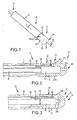
- FIG 1 is an isometric view of part of an embodiment of an irrigated ablation catheter assembly 10.
- the irrigated ablation catheter assembly 10 includes an open irrigated ablation electrode 12 connected to a catheter shaft 14 having at least one fluid delivery tube 16 therein.
- the ablation electrode 12 includes an outer body portion 18 having an outer surface 20, and includes a proximal portion 22 and a distal portion 24.
- electrode 12 of the catheter assembly 10 may further include an inner cavity 26 that may be coupled to or is in fluid communication with fluid delivery tube 16.
- the open irrigated electrode 12 further includes at least one fluid or irrigation passageway 28 that extends from inner cavity 26 to outer surface 20 of electrode 12.
- Electrode 12 may be comprised of any electrically, and potentially thermally, conductive material known to those of ordinary skill in the art for delivery of ablative energy to target tissue areas.
- electrically conductive materials include gold, platinum, iridium, palladium, stainless steel, and mixtures thereof.
- a portion of electrode 12 may be configured to connect to (or be received by) catheter shaft 14 of catheter assembly 10 therein coupling electrode 12 to form an embodiment of a catheter assembly 10. It is noted that alternate configurations may be employed with other embodiments in which an electrode may be comprised of multiple members that connect or fit together to form the electrode.
- Various materials may be used in the formation of such electrodes, including a combination of electrically conductive materials and materials that are less thermally conductive.
- outer body portion 18 of electrode 20, which includes outer surface 20, is generally cylindrical in shape and terminates in a hemispherical end.
- outer body portion 18 may be provided in alternate configurations that may be directed to the design of the catheter assembly and/or the procedures being performed.
- Proximal portion 22 of electrode 12 is generally adjacent to catheter shaft 14, and may be disposed on the distal end of catheter shaft 14.
- Distal portion 24 of electrode 12 is generally more remote from catheter shaft 14 and includes the portion of electrode 12 intended to come into operative contact with tissue.
- Distal portion 24 further includes a distal end 36 which may be generally hemispherical, although other shapes and configurations are also contemplated by the present invention.
- Proximal portion 22 of electrode 12 may further include a mounting portion, such as mounting shaft 34 that is provided on or in connection with the proximal end 30 of electrode 12.
- Mounting shaft 34 may be connected to or an integral part of proximal end 30 of proximal portion 22 of electrode 12 and may be received within or otherwise connected to catheter shaft 14 of assembly 12.
- coupling member 32 is disposed between mounting shaft 34 and catheter shaft 14.
- a coupling member 32 such as a seal or adhesive, is provided to ensure that electrode 12 is connected to catheter shaft 14.
- Coupling member 32 is generally known in the art and includes any type of material known for such a purpose to those of ordinary skill in the art.
- coupling member 32 may have alternate configurations or arrangements to connect electrode 12 with catheter shaft 14.
- Electrode 12 may further include a temperature or thermal sensor 40 (generally represented in Figures 2 and 3 ) positioned within distal portion 24 of electrode 12.
- Thermal sensor 40 may be configured and positioned to provide improved or optimized accurate temperature sensing by electrode 12 as ablative energy is applied by catheter assembly 10.
- a lead wire 42 may be coupled to thermal sensor 40 and may extend along the catheter assembly 12 such that the temperature of electrode 12 may be communicated to a processor or controller within the catheter assembly system to help control overall system operation and regulation of the irrigation fluid flow and ablation performed by the catheter assembly system.
- the configuration of thermal sensor 40 may be modified to work with various designs of open irrigation catheter assemblies.
- more than one thermal sensor 40 may be provided in connection with an electrode. In embodiments in which a plurality of sensors 40 are provided, the sensors may be used in combination to provide temperature readings associated with an electrode 12.
- inner cavity 26 of electrode 12 includes a central longitudinal axis 38 that extends along the length of electrode 12.
- Inner cavity 26 may have a generally tubular configuration, although alternate embodiments of the inner cavity are also contemplated. In the illustrated embodiment, inner cavity 26 extends through proximal portion 22 and into distal portion 24 of electrode 12.
- an open irrigation electrode 12 includes at least one fluid passageway 28 -- such as, without limitation, passageways 28a and/or 28b shown in Figure 2 ).
- Such passageway(s) 28 may include and be referred to as conduit(s), irrigation port(s), irrigation hole(s), channel(s), or other types of structures employed by those of skill in the art.
- passageway 28 extends from internal cavity 26 to an outer surface 20 of electrode 12.
- some open irrigation electrodes such as those illustrated in Figures 2 and 3 , may include at least one passageway 28a that is perpendicular, or substantially perpendicular, to the central longitudinal axis 38 of electrode 12.
- passageway 28b may be provided that extends along central longitudinal axis 38 from inner cavity 26 to distal end 36 to provide irrigation at distal portion 24 of electrode 12.
- passageways 28 are disposed circumferentially around electrode 12.
- the passageways may be provided so that they are generally equidistant from one another, although alternate configurations and placements of passageway 28 may be used depending on the design or desired performance (e.g., to cover a given volume of fluid flow) of electrode 12.
- the design of the passageways 28 may be modified to obtain a desired flow rate of the irrigation fluid based on a temperature threshold set by the overall system.
- the size and configuration of passageway 28 (such as 28a and/or 28b) may be varied depending on the size and design of an associated electrode 12.
- the diameter of passageway 28 may range from 10-20 thousandths of an inch.
- the diameter of the passageway 28 may range from 12-16 thousandths of an inch.
- the flow rate and/or volume of fluid flow may range from 13-20 ml/min.
- the diameter size of passageway 28 may be configured to permit a given flow volume or rate, and further may be varied in connection with the number of passageways provided by electrode 12, as well as the length of the electrode, or with other features associated with the electrode or catheter assemblies.
- electrode 12 may include additional components, such as those typically used by ablation electrodes, including but not limited to pressure sensors, power wires, or other features or components traditionally integrated with catheter assemblies.
- An open irrigation catheter assembly 12 such as generally described above, may be integrated into alternate embodiments of catheter assembly system 50s, for example, as shown in Figures 4 and 5 .
- System 50, 50' may be configured to control and regulate the flow of irrigation fluid such that the relative positioning of the electrode and establishment of sufficient or improved physical contact is, at least in part, facilitated by a temperature feedback provided by electrode 12.
- catheter assembly 10 may be operably connected to a fluid source 52 (e.g ., a pump assembly) and an energy source 54 (e.g., an RF generator assembly), together comprising an embodiment of a catheter system 50.
- the fluid source 52 and energy source 54 may serve to facilitate operation of ablation procedures and may involve monitoring any number of chosen variables (e.g., temperature of ablation electrode, ablation energy, and/or position of the assembly), assisting in manipulation of the assembly during the use, and providing the requisite energy from a source that is delivered to the electrode 12.
- additional components may be integrated into the system.
- such additional components may include visualization, mapping and navigation components known in the art, including St. Jude Medical, Inc.'s NavX ® system or other related systems.
- fluid source 52 and energy source 54 may be provided in combination with a catheter assembly 10 to comprise a system 50.
- Fluid source 52 can comprise various known fluid sources, including fixed volume rolling pumps, variable volume syringe pumps, and various other pump assemblies known to those skilled in the art.
- the fluid provided by fluid source 52 may comprise a suitable biocompatible fluid, such as saline.
- the energy source 54 may comprise, for example and without limitation, an IBI-1500T RF Cardiac Ablation Generator available from Irvine Biomedical, Inc.
- the energy source can also comprise various other known energy sources.
- energy source 54 may also, if desired, be configured with a temperature threshold setting and pump control switch (not shown).
- energy source 54 may monitor and detect the temperature of electrode 12 of catheter assembly 10 and, once an established temperature threshold is met, activate fluid source 52, therein either increasing/decreasing fluid flow or turning the pump completely on or off.
- Figure 4 generally illustrates a system having a closed control loop to control the flow of irrigation fluid, e.g., saline, based on the temperature feedback provided by catheter assembly 10.
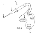
- FIG. 5 generally illustrates another embodiment of the invention wherein system 50' integrates a controller 56, such as, for example, a computer or other type of processor or signal control device.
- Controller 56 may be configured to receive input from energy source 54. Input received by controller 56 may further include temperature readings obtained from catheter assembly 10 (such as those provided in connection with a thermal sensor 40 of electrode 12). Controller 56 can process temperature readings and make comparisons/calculations with respect to specified temperature threshold levels. Once a desired temperature threshold levels is established or obtained, controller 56 can output a signal to pump 52, which can in turn control irrigation fluid flow supplied to catheter assembly 12.
- controller 56 may modify its signal (e.g ., instructions) to pump 52, which can increase or decrease the associated fluid flow.
- Various data such as, for example, irrigation fluid flow (cc/min), temperature measurements, duration of fluid flow, and electrode temperature response may be processed by controller 56.
- controller 56 may also help assess (e.g., chart) various data or parameters, which may be reviewed by a user.
- the system 50 can provide for dynamic assessment and review.
- irrigation fluid flow may initially be delayed following application of ablation energy.
- the delay in irrigation fluid flow may either be obtained through a fixed delay or a variable delay.
- the fixed delay may occur, for example, when irrigation flow is delayed for a fixed or predetermined period of time, such as, for example, 10-30 seconds after the start of the ablation energy. After a fixed period of time has passed, the irrigation fluid may be provided to the catheter assembly.
- a variable delay may occur, for example, when irrigation flow is controlled by a predetermined temperature threshold. In a particular embodiment, the variable delay may occur and continue until a temperature threshold level, e.g., 65 degrees Celsius, is reached and then a constant irrigation fluid flow can be provided and maintained for the duration of the ablation procedure.
- Figure 8 illustrates an embodiment of an intermitted irrigation fluid flow and a correlation between irrigated fluid flow and resulting electrode temperature response.
- the intermitted irrigation flow may occur for either a fixed intermitted duration or for a variable intermitted duration.
- the fixed intermitted duration may, for example, occur for a predefined period of time, e.g., approximately 10-20 seconds, and then return back to a maintenance flow level ( e.g ., 2 cc/min). This flow control can occur for and throughout an entire ablation procedure.
- a variable intermitted duration may be controlled by an upper predetermined electrode temperature threshold level (e.g ., ranging from 50-70 degrees Celsius) and a lower predetermined electrode temperature threshold level (e.g ., ranging from 37-45 degrees Celsius).
- a maintenance irrigation flow level may be initially present (e.g ., 2 cc/min), until an upper predetermined threshold level is reached and then irrigation fluid flow may be initiated.
- the irrigation fluid flow can be configured to continue until a lower predetermined electrode temperature threshold level is reached, at which point the irrigation fluid flow may be decreased to return to a maintenance flow level.
- the foregoing can continue in the form of a cycle or loop, which can result in an intermitted fluid flow throughout an entire ablation procedure.
- the irrigation flow may be turned off periodically during the ablation procedure to check the temperature response of the electrode until the ablation is completely.
- a temperature threshold may be preset in connection with a generator 54.
- the temperature threshold level may range from 50-70 degrees Celsius, and for some embodiments may preferably be about 65 degrees Celsius.
- the present invention further provides a method of irrigating biological tissue.
- the method can be initiated by providing an irrigated catheter ablation system 50, 50'.
- the system 50, 50' can include an irrigated ablation catheter assembly, a fluid source connected to the catheter assembly, an energy source connected to the catheter assembly, and an irrigation temperature control mechanism in communication with the fluid source and energy source.
- the irrigated ablation catheter assembly 10 may be in accordance with teachings previously described.
- the method may include a step of establishing or presetting a temperature threshold for the system that regulates irrigation fluid flow from the passageway of the catheter assembly.
- the irrigated electrode of the irrigated ablation catheter assembly may be operatively positioned at a target location. Energy may then applied to the target location via an irrigated electrode.
- Temperature measurements associated with an electrode may be continuously collected. The temperature measurements can be continuously taken by a thermal sensor disposed within an irrigated electrode. After either a fixed period of time (fixed delay) or upon the temperature measurement reaching a temperature threshold level (variable delay), irrigation flow may be initiated or increased (if an original (e.g ., maintenance flow was already present) to cool the electrode. Irrigation may continue until ablation is discontinued. As previously described, an application of fixed delay irrigation may cause the irrigation flow to be initiated, for example, about 10 to approximately 30 seconds after the application of the ablation energy was applied. In comparison, if variable delay irrigation is performed, the irrigation may be initiated after an upper temperature threshold level is reached, e.g ., at about 50-70 degrees Celsius.
- Another embodiment further includes a method of irrigating biological tissue involving an intermitted irrigation flow.
- additional temperature measurements of the irrigated electrode can be collected until a predetermined lower threshold is reached. Once a predetermined lower threshold level is reached, the irrigation flow may be discontinued. Temperatures can continued to be monitored and collected. If temperature measurements reach an upper temperature threshold level again, irrigation flow can be initiated or re-initiated, as the case may be. Such an intermitted irrigation cycle can continue until the ablation is formed. Alternately, the irrigation flow may be turned off periodically during the ablation procedure to check the temperature response of the electrode until the ablation is completely.
- joinder references do not necessarily infer that two elements are directly connected and in fixed relation to each other. It is intended that all matter contained in the above description or shown in the accompanying drawings shall be interpreted as illustrative only and not limiting. Changes in detail or structure may be made without departing from the spirit of the invention as defined in the appended claims.
Abstract
Description
- The present invention relates to irrigated catheter assembly systems and methods for ablating tissue using controlled irrigation flow. The present invention further relates to open irrigated catheter ablation systems having irrigation fluid flow that may be regulated in connection with a predetermined temperature threshold.
- Electrophysiology catheters are used for an ever-increasing number of procedures. For example, catheters are used for diagnostic, therapeutic, and ablative procedures, to name just a few procedures. Typically, a catheter is manipulated through the patient's vasculature to an intended site, for example, a site within the patient's heart. The catheter commonly carries one or more electrodes, which may be used for ablation, diagnosis, and/or other treatments.
- There are a number of methods used for ablation of desired areas, including for example, radiofrequency (RF) ablation. RF ablation is accomplished by transmission of radiofrequency energy to a desired target area through an electrode assembly to ablate tissue at a target site. Because RF ablation may generate significant heat, which if not controlled could result in tissue damage, such as steam pop, tissue charring, and the like, it is often desirable to include a mechanism to irrigate the target area and the device with biocompatible fluids, such as saline solution. The use of fluid irrigated ablation catheters can also prevent the formation of soft thrombus and/or blood coagulation.
- Generally, there are two classes of irrigated electrode catheters, open and closed irrigation catheters. Closed ablation catheters can circulate a cooling fluid within the inner cavity of the ablation electrode. Open ablation catheters can deliver the cooling fluid through open outlets or openings on the surface of the electrode. Open ablation catheters use the inner cavity of the electrode, or distal member, as a manifold to distribute saline solution (or other irrigation fluids known to those skilled in the art) to one or more passageways that lead to openings/outlets provided on the surface of the electrode. The saline thus flows directly through the outlets of the passageways onto or about the distal electrode member. This direct flow through the distal electrode tip lowers the temperature of the distal tip during operation, which may make accurate monitoring and control of the ablation process somewhat more challenging.
- While open irrigated ablation catheters may improve the safety of RF catheter ablation by preventing protein aggregation and blood coagulation through the dissipation of heat by providing fluid to the site during the ablation procedure, direct contacting fluid irrigation has the tendency to cool the electrode temperature dramatically during ablation procedures. The irrigation fluid flow ultimately cuts off the electrode temperature from rising, which may result in increased (and possibly more than desirable) ablation in a target area. As such, it can be desirable to control and more accurately monitor the temperature of an electrode performing ablation.
- The present invention is directed to improved open irrigated catheter ablation systems and methods used in connection with open irrigated catheter systems. Among other things, systems and related methods are provided that can control irrigation fluid flow and obtain an effective temperature response with respect to an ablation procedure. Embodiments of the present invention provide an irrigated catheter ablation system having controlled irrigation fluid flow directed at target areas, for example, where coagulation is more likely to occur so as to minimize blood coagulation and associated problems. The irrigated fluid flow may be regulated in connection with a predetermined temperature threshold to improve or better optimize cooling and ablation properties associated with the system.
- The present invention provides an ablation system having an open irrigated ablation electrode coupled to or connected with a catheter shaft forming an open irrigated catheter assembly in connection with a fluid source, an energy source, and a temperature control mechanism for regulating irrigation fluid flow within the catheter shaft assembly. The fluid source preferably includes a saline pump. The irrigation temperature control mechanism preferably includes a controller.
- The present invention further discloses an ablation system having an open irrigated ablation catheter assembly including an open irrigated ablation electrode coupled to or connected to a catheter shaft forming the open irrigated catheter assembly in connection with a fluid source, an energy source, such as, for example, radio frequency (RF) generator, and a processor for regulating the temperature control of the electrode performing the ablation.
- The present invention provides a method of controlling the irrigation of biological tissue. The method includes the steps of providing an irrigated catheter ablation system including an irrigated ablation catheter assembly, a fluid source connected to the catheter assembly, an energy source connected to the catheter assembly; and an irrigation temperature control mechanism in communication with the fluid source and energy source; presetting a temperature threshold for the system that regulates irrigation fluid flow from the passageway of the catheter assembly; positioning the irrigated electrode of the irrigated ablation catheter assembly at a target location; applying energy from the energy source to the target location through the irrigated electrode; collecting temperature measurements from a thermal sensor disposed within the irrigated electrode; irrigating the ablation electrode forming an irrigation flow through the passageway of the electrode; and completing the application of energy to the target location to form an ablation lesion.
- The invention further contemplates alternate methods for irrigating biological tissue, including a delayed irrigation method and an intermitted irrigation method. The delayed irrigation method involves collecting temperature measurements of the open irrigation electrode until the collected temperature measurements of the electrode reach a predetermined upper temperature threshold. Once the upper temperature threshold is met, the irrigation fluid flow from the passageways of the open irrigation electrode increases from a maintenance flow rate to an amplified irrigation flow rate. The increased irrigation flow continues until the ablation is completed. In comparison, during the intermitted irrigation method, once the irrigation fluid flow from the passageways of the open irrigation electrode is increased, the intermitted method further includes collecting temperature measurements of the electrode until the temperature measurements of the electrode reach a predetermined lower temperature threshold. Once the electrode temperature measurements reach the lower threshold level, the irrigation flow is reduced to the maintenance flow level through the passageway of the electrode. Once the irrigation flow is reduced, temperature measurements continue to be collected from a thermal sensor disposed within the irrigated electrode until the temperature measurements once again return to the predetermined upper temperature threshold. The irrigation fluid flow is then increased again through the passageway of the electrode therein creating an intermitted irrigation cycle. Accordingly, the irrigation flow is reduced periodically during the intermitted irrigation cycle in response to the temperature. The intermitted irrigation cycle is continued until the ablation is complete. The intermitted irrigation method further provides that the irrigation may be turned off periodically during the ablation procedure to check the temperature response of the electrode until the ablation is completely.
- The foregoing and other aspects, features, details, utilities, and advantages of the present invention will be apparent from reading the following description and claims, and from reviewing the accompanying drawings.
-
-
Figure 1 is an isometric view of an ablation electrode according to an embodiment of the present invention; -
Figure 2 is a cross-sectional view of an ablation electrode of the type generally shown inFigure 1 ; -
Figure 3 is a cross-sectional view of an ablation electrode according to another embodiment of the present invention; -
Figure 4 is an isometric view of an ablation catheter system according to an embodiment of the present invention, the illustrated system including an irrigated catheter assembly operably connected to an energy source and a fluid source; -
Figure 5 is an isometric view of an ablation catheter system according to another embodiment of the present invention, the illustrated system including an irrigated catheter assembly operably connected to an energy source, a fluid source, and a processor; -
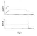
Figure 6 is a graphical representation of a conventional tip electrode temperature response and irrigation flow according to the prior art; -
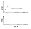
Figure 7 is a graphical representation of the tip electrode temperature response and delayed irrigation flow rate according to an embodiment of the present invention; and -
Figure 8 is an graphical representation of the tip electrode temperature response and intermitted irrigation flow according to an embodiment of the present invention. - In general, the instant invention relates to irrigated catheter ablation systems and to methods of using irrigated catheter ablation systems. For purposes of this description, similar aspects among the various embodiments described herein will generally be referred to by the same reference number. As will be appreciated, however, the structure of the various aspects may differ among various embodiments.
- Open irrigated catheter ablation systems of the present invention include an irrigated
ablation catheter assembly 10, as generally shown inFigure 1 . The illustrated irrigatedablation catheter assembly 10 includes anablation electrode 12. While embodiments of the invention disclosed herein may describe RF ablation catheter assemblies and related systems, the invention is not so limited, and the invention may include or involve other types of ablation electrodes and assemblies in which the temperature of the device and a targeted tissue area may be factors during the procedure.Figures 2 and 3 , discussed in further detail below, illustrate specific openirrigated ablation electrodes 10 according to alternate embodiments associated with the present invention. Moreover,Figures 4 and5 , discussed in further detail below, illustrate catheter ablation systems embodying features associated with the present invention. - Embodiments of open irrigated catheter ablation systems in accordance with the present invention include an open
irrigated catheter assembly 10 having an openirrigated electrode 12 configured to control the flow of irrigation fluid to an ablation site. The present invention encompasses irrigated catheter assembly systems that control and regulate the irrigation fluid flow to an ablation site, for example, to improve or optimized ablation on a tissue while irrigating the surface of the tissue. The system may be configured and/or regulated to provide either intermitted irrigation fluid flow throughout the ablation procedure or a delayed onset of irrigation to ensure good physical contact ofelectrode 12 with the ablation site. In embodiments, temperature feedback may be used in combination with responsive irrigation flow to improve or optimize tissue ablation when using convention open irrigated ablation catheters to perform an ablation procedure or technique on biological tissue. Such conventional irrigation catheters include, but are not limited to, those such as IBI Therap™ Cool Path™ Ablation Catheter available from Irvine Biomedical, Inc. - In particular, one embodiment of the present invention provides a system and related method for performing RF ablation that includes the delayed onset of the irrigation fluid flow to
electrode 12. The onset of therapeutic irrigation fluid flow may be controllably delayed untilelectrode 12 reaches a predetermined temperature threshold, such as, without limitation, about 65 degrees Celsius. With such embodiments, afterelectrode 12 reaches the temperature threshold level, the irrigation fluid flow can be started to provide cooling to the electrode. The delayed onset of the irrigation flow better ensures that an accurate temperature reading of the electrode may be obtained during the initial ablation procedure, which further helps ensure improved physical contact betweenelectrode 12 and a targeted site (e.g., targeted tissue). On the other hand, if the temperature threshold is not met upon the application of the ablation energy or shortly thereafter,electrode 12 may need to be repositioned to ensure sufficient or proper physical contact with targeted tissue. Since the temperature threshold is generally set below an associated safety limit, e.g., about 65 degrees C, heat related coagulum that is present can be eliminated in connection with the ablation. - An alternate embodiment of the present invention provides a system and related method for performing ablation, such as RF ablation, that includes intermitted fluid irrigation flow such that irrigation fluid may be regulated (i.e., increased and decreased) in response to the temperature of
electrode 12. More particularly, the intermitted fluid irrigation flow may be controlled by a predetermined temperature threshold, such as, for example, about 65 degrees. Accordingly, the irrigation fluid flow may be increased when the electrodes reaches about 65 degrees and is then decreased once a reduced temperature threshold is reached, such as, for example about 40 degrees. The irrigation fluid flow may be provided for a fixed intermitted duration (i.e., for example, a fixed period of time), a variable intermitted duration that is based solely on temperature threshold levels, or some combination of the foregoing. - As noted, open irrigated catheter assemblies may be used for a variety of treatments and procedures.
Figure 1 is an isometric view of part of an embodiment of an irrigatedablation catheter assembly 10. The irrigatedablation catheter assembly 10 includes an openirrigated ablation electrode 12 connected to acatheter shaft 14 having at least onefluid delivery tube 16 therein. Theablation electrode 12 includes anouter body portion 18 having anouter surface 20, and includes aproximal portion 22 and adistal portion 24. As further illustrated inFigures 2 and 3 ,electrode 12 of thecatheter assembly 10 may further include aninner cavity 26 that may be coupled to or is in fluid communication withfluid delivery tube 16. The open irrigatedelectrode 12 further includes at least one fluid orirrigation passageway 28 that extends frominner cavity 26 toouter surface 20 ofelectrode 12. -
Electrode 12 may be comprised of any electrically, and potentially thermally, conductive material known to those of ordinary skill in the art for delivery of ablative energy to target tissue areas. Examples of electrically conductive materials include gold, platinum, iridium, palladium, stainless steel, and mixtures thereof. A portion ofelectrode 12 may be configured to connect to (or be received by)catheter shaft 14 ofcatheter assembly 10 therein couplingelectrode 12 to form an embodiment of acatheter assembly 10. It is noted that alternate configurations may be employed with other embodiments in which an electrode may be comprised of multiple members that connect or fit together to form the electrode. Various materials may be used in the formation of such electrodes, including a combination of electrically conductive materials and materials that are less thermally conductive. - In the illustrated embodiment,
outer body portion 18 ofelectrode 20, which includesouter surface 20, is generally cylindrical in shape and terminates in a hemispherical end. However,outer body portion 18 may be provided in alternate configurations that may be directed to the design of the catheter assembly and/or the procedures being performed.Proximal portion 22 ofelectrode 12 is generally adjacent tocatheter shaft 14, and may be disposed on the distal end ofcatheter shaft 14.Distal portion 24 ofelectrode 12 is generally more remote fromcatheter shaft 14 and includes the portion ofelectrode 12 intended to come into operative contact with tissue.Distal portion 24 further includes adistal end 36 which may be generally hemispherical, although other shapes and configurations are also contemplated by the present invention. -
Proximal portion 22 ofelectrode 12 may further include a mounting portion, such as mountingshaft 34 that is provided on or in connection with the proximal end 30 ofelectrode 12. Mountingshaft 34 may be connected to or an integral part of proximal end 30 ofproximal portion 22 ofelectrode 12 and may be received within or otherwise connected tocatheter shaft 14 ofassembly 12. In an embodiment,coupling member 32 is disposed between mountingshaft 34 andcatheter shaft 14. Acoupling member 32, such as a seal or adhesive, is provided to ensure thatelectrode 12 is connected tocatheter shaft 14. Couplingmember 32 is generally known in the art and includes any type of material known for such a purpose to those of ordinary skill in the art. Moreover,coupling member 32 may have alternate configurations or arrangements to connectelectrode 12 withcatheter shaft 14. -
Electrode 12 may further include a temperature or thermal sensor 40 (generally represented inFigures 2 and 3 ) positioned withindistal portion 24 ofelectrode 12.Thermal sensor 40 may be configured and positioned to provide improved or optimized accurate temperature sensing byelectrode 12 as ablative energy is applied bycatheter assembly 10. Alead wire 42 may be coupled tothermal sensor 40 and may extend along thecatheter assembly 12 such that the temperature ofelectrode 12 may be communicated to a processor or controller within the catheter assembly system to help control overall system operation and regulation of the irrigation fluid flow and ablation performed by the catheter assembly system. The configuration ofthermal sensor 40 may be modified to work with various designs of open irrigation catheter assemblies. Moreover, more than onethermal sensor 40 may be provided in connection with an electrode. In embodiments in which a plurality ofsensors 40 are provided, the sensors may be used in combination to provide temperature readings associated with anelectrode 12. - With reference to
Figures 2 and 3 ,inner cavity 26 ofelectrode 12 includes a centrallongitudinal axis 38 that extends along the length ofelectrode 12.Inner cavity 26 may have a generally tubular configuration, although alternate embodiments of the inner cavity are also contemplated. In the illustrated embodiment,inner cavity 26 extends throughproximal portion 22 and intodistal portion 24 ofelectrode 12. - As shown in
Figures 2 and 3 , anopen irrigation electrode 12 includes at least onefluid passageway 28 -- such as, without limitation,passageways 28a and/or 28b shown inFigure 2 ). Such passageway(s) 28 may include and be referred to as conduit(s), irrigation port(s), irrigation hole(s), channel(s), or other types of structures employed by those of skill in the art. In general,passageway 28 extends frominternal cavity 26 to anouter surface 20 ofelectrode 12. Moreover, some open irrigation electrodes, such as those illustrated inFigures 2 and 3 , may include at least onepassageway 28a that is perpendicular, or substantially perpendicular, to the centrallongitudinal axis 38 ofelectrode 12. In addition, as generally shown inFigure 2 ,passageway 28b may be provided that extends along centrallongitudinal axis 38 frominner cavity 26 todistal end 36 to provide irrigation atdistal portion 24 ofelectrode 12. - In addition to those configurations reflected in
Figures 2 and 3 , various alternative embodiments of fluid passageways may be incorporated withinelectrode 12, such as those described in currently pending applications assignedU.S. Patent Application Serial Nos. 11/939,195 and11/939,206 electrode 12. In embodiments, the passageways may be provided so that they are generally equidistant from one another, although alternate configurations and placements ofpassageway 28 may be used depending on the design or desired performance (e.g., to cover a given volume of fluid flow) ofelectrode 12. - Accordingly, the design of the
passageways 28 may be modified to obtain a desired flow rate of the irrigation fluid based on a temperature threshold set by the overall system. The size and configuration of passageway 28 (such as 28a and/or 28b) may be varied depending on the size and design of an associatedelectrode 12. In an embodiment, the diameter ofpassageway 28 may range from 10-20 thousandths of an inch. In another embodiment, the diameter of thepassageway 28 may range from 12-16 thousandths of an inch. Moreover, the flow rate and/or volume of fluid flow may range from 13-20 ml/min. The diameter size ofpassageway 28 may be configured to permit a given flow volume or rate, and further may be varied in connection with the number of passageways provided byelectrode 12, as well as the length of the electrode, or with other features associated with the electrode or catheter assemblies. - In addition to various passageway networks and configurations,
electrode 12 may include additional components, such as those typically used by ablation electrodes, including but not limited to pressure sensors, power wires, or other features or components traditionally integrated with catheter assemblies. - An open
irrigation catheter assembly 12, such as generally described above, may be integrated into alternate embodiments of catheter assembly system 50s, for example, as shown inFigures 4 and5 .System 50, 50' may be configured to control and regulate the flow of irrigation fluid such that the relative positioning of the electrode and establishment of sufficient or improved physical contact is, at least in part, facilitated by a temperature feedback provided byelectrode 12. - As generally shown in the embodiment illustrated in
Figure 4 ,catheter assembly 10 may be operably connected to a fluid source 52 (e.g., a pump assembly) and an energy source 54 (e.g., an RF generator assembly), together comprising an embodiment of acatheter system 50. Thefluid source 52 andenergy source 54 may serve to facilitate operation of ablation procedures and may involve monitoring any number of chosen variables (e.g., temperature of ablation electrode, ablation energy, and/or position of the assembly), assisting in manipulation of the assembly during the use, and providing the requisite energy from a source that is delivered to theelectrode 12. Furthermore, additional components may be integrated into the system. By way of example, without limitation, such additional components may include visualization, mapping and navigation components known in the art, including St. Jude Medical, Inc.'s NavX® system or other related systems. - As generally represented in
Figure 4 ,fluid source 52 andenergy source 54 may be provided in combination with acatheter assembly 10 to comprise asystem 50.Fluid source 52 can comprise various known fluid sources, including fixed volume rolling pumps, variable volume syringe pumps, and various other pump assemblies known to those skilled in the art. Moreover, the fluid provided byfluid source 52, may comprise a suitable biocompatible fluid, such as saline. Theenergy source 54 may comprise, for example and without limitation, an IBI-1500T RF Cardiac Ablation Generator available from Irvine Biomedical, Inc. The energy source can also comprise various other known energy sources. In order to obtain controlled/regulated fluid flow within the system,energy source 54 may also, if desired, be configured with a temperature threshold setting and pump control switch (not shown). In an embodiment, energy source 54 (i.e., generator) may monitor and detect the temperature ofelectrode 12 ofcatheter assembly 10 and, once an established temperature threshold is met, activatefluid source 52, therein either increasing/decreasing fluid flow or turning the pump completely on or off. Accordingly,Figure 4 generally illustrates a system having a closed control loop to control the flow of irrigation fluid, e.g., saline, based on the temperature feedback provided bycatheter assembly 10. -
Figure 5 generally illustrates another embodiment of the invention wherein system 50' integrates acontroller 56, such as, for example, a computer or other type of processor or signal control device.Controller 56 may be configured to receive input fromenergy source 54. Input received bycontroller 56 may further include temperature readings obtained from catheter assembly 10 (such as those provided in connection with athermal sensor 40 of electrode 12).Controller 56 can process temperature readings and make comparisons/calculations with respect to specified temperature threshold levels. Once a desired temperature threshold levels is established or obtained,controller 56 can output a signal to pump 52, which can in turn control irrigation fluid flow supplied tocatheter assembly 12. Continued (periodic or continuous) temperature readings fromcatheter assembly 10 may be provided tocontroller 56 and based on changes in the temperature readings ofcatheter assembly 10,controller 56 may modify its signal (e.g., instructions) to pump 52, which can increase or decrease the associated fluid flow. Various data, such as, for example, irrigation fluid flow (cc/min), temperature measurements, duration of fluid flow, and electrode temperature response may be processed bycontroller 56. In an embodiment,controller 56 may also help assess (e.g., chart) various data or parameters, which may be reviewed by a user. Moreover, thesystem 50 can provide for dynamic assessment and review. - As represented in
Figures 6-8 , temperature readings of anelectrode 10 ofcatheter assembly 12 and the provision of irrigation fluid have a direct correlation with one another. As generally shown inFigure 6 , the conventional method of introducing irrigation fluid upon the onset of the ablation procedure results in the electrode temperature only reaching approximately 40 degrees Celsius. However, this can result in less effective ablation with respect to a target area and there may be some regulation difficulties if the ablation electrode is in direct contact with the target tissue. In comparison,Figures 7 and8 , without limitation, illustrate delayed and intermitted irrigation, respectively, in accordance with embodiments of the present invention. - As generally shown in
Figure 7 , irrigation fluid flow may initially be delayed following application of ablation energy. The delay in irrigation fluid flow may either be obtained through a fixed delay or a variable delay. The fixed delay may occur, for example, when irrigation flow is delayed for a fixed or predetermined period of time, such as, for example, 10-30 seconds after the start of the ablation energy. After a fixed period of time has passed, the irrigation fluid may be provided to the catheter assembly. In contrast, a variable delay may occur, for example, when irrigation flow is controlled by a predetermined temperature threshold. In a particular embodiment, the variable delay may occur and continue until a temperature threshold level, e.g., 65 degrees Celsius, is reached and then a constant irrigation fluid flow can be provided and maintained for the duration of the ablation procedure. -
Figure 8 illustrates an embodiment of an intermitted irrigation fluid flow and a correlation between irrigated fluid flow and resulting electrode temperature response. The intermitted irrigation flow may occur for either a fixed intermitted duration or for a variable intermitted duration. The fixed intermitted duration may, for example, occur for a predefined period of time, e.g., approximately 10-20 seconds, and then return back to a maintenance flow level (e.g., 2 cc/min). This flow control can occur for and throughout an entire ablation procedure. In other embodiments, a variable intermitted duration may be controlled by an upper predetermined electrode temperature threshold level (e.g., ranging from 50-70 degrees Celsius) and a lower predetermined electrode temperature threshold level (e.g., ranging from 37-45 degrees Celsius). Accordingly, only a maintenance irrigation flow level may be initially present (e.g., 2 cc/min), until an upper predetermined threshold level is reached and then irrigation fluid flow may be initiated. The irrigation fluid flow can be configured to continue until a lower predetermined electrode temperature threshold level is reached, at which point the irrigation fluid flow may be decreased to return to a maintenance flow level. The foregoing can continue in the form of a cycle or loop, which can result in an intermitted fluid flow throughout an entire ablation procedure. Alternately, the irrigation flow may be turned off periodically during the ablation procedure to check the temperature response of the electrode until the ablation is completely. - In accordance with the embodiments of the present invention, and performing ablation of biological tissue through the use of open irrigated catheter assemblies, a temperature threshold may be preset in connection with a
generator 54. In embodiments, the temperature threshold level may range from 50-70 degrees Celsius, and for some embodiments may preferably be about 65 degrees Celsius. After a temperature threshold level is set or otherwise established, an open irrigatedablation catheter assembly 10 can be maneuvered to a target location (such as, for example, the surface of the heart). Onceelectrode 12 ofcatheter assembly 10 is provided at a desired target position, energy can be applied bygenerator 54 toelectrode 10. - The present invention further provides a method of irrigating biological tissue. The method can be initiated by providing an irrigated
catheter ablation system 50, 50'. Thesystem 50, 50' can include an irrigated ablation catheter assembly, a fluid source connected to the catheter assembly, an energy source connected to the catheter assembly, and an irrigation temperature control mechanism in communication with the fluid source and energy source. The irrigatedablation catheter assembly 10 may be in accordance with teachings previously described. The method may include a step of establishing or presetting a temperature threshold for the system that regulates irrigation fluid flow from the passageway of the catheter assembly. The irrigated electrode of the irrigated ablation catheter assembly may be operatively positioned at a target location. Energy may then applied to the target location via an irrigated electrode. Temperature measurements associated with an electrode may be continuously collected. The temperature measurements can be continuously taken by a thermal sensor disposed within an irrigated electrode. After either a fixed period of time (fixed delay) or upon the temperature measurement reaching a temperature threshold level (variable delay), irrigation flow may be initiated or increased (if an original (e.g., maintenance flow was already present) to cool the electrode. Irrigation may continue until ablation is discontinued. As previously described, an application of fixed delay irrigation may cause the irrigation flow to be initiated, for example, about 10 to approximately 30 seconds after the application of the ablation energy was applied. In comparison, if variable delay irrigation is performed, the irrigation may be initiated after an upper temperature threshold level is reached, e.g., at about 50-70 degrees Celsius. - Another embodiment further includes a method of irrigating biological tissue involving an intermitted irrigation flow. In addition to the steps discussed above, additional temperature measurements of the irrigated electrode can be collected until a predetermined lower threshold is reached. Once a predetermined lower threshold level is reached, the irrigation flow may be discontinued. Temperatures can continued to be monitored and collected. If temperature measurements reach an upper temperature threshold level again, irrigation flow can be initiated or re-initiated, as the case may be. Such an intermitted irrigation cycle can continue until the ablation is formed. Alternately, the irrigation flow may be turned off periodically during the ablation procedure to check the temperature response of the electrode until the ablation is completely.
- Although a number of embodiments of this invention have been described above with a certain degree of particularity, those skilled in the art could make numerous alterations to the disclosed embodiments without departing from the spirit or scope of this invention. All directional references (e.g., upper, lower, upward, downward, left, right, leftward, rightward, top, bottom, above, below, vertical, horizontal, clockwise, and counterclockwise) are only used for identification purposes to aid the reader's understanding of the present invention, and do not create limitations, particularly as to the position, orientation, or use of the invention. Joinder references (e.g., attached, coupled, connected, and the like) are to be construed broadly and may include intermediate members between a connection of elements and relative movement between elements. As such, joinder references do not necessarily infer that two elements are directly connected and in fixed relation to each other. It is intended that all matter contained in the above description or shown in the accompanying drawings shall be interpreted as illustrative only and not limiting. Changes in detail or structure may be made without departing from the spirit of the invention as defined in the appended claims.
- The following is a listing of various aspects of the invention:
- 1. An irrigated catheter ablation system comprising: an irrigated ablation catheter assembly including: an irrigated electrode having a proximal portion with a proximal end, a distal portion with a distal end, an outer body portion, including an outer surface, an inner cavity defined within the outer body portion, and at least one passageway that extends from the inner cavity to the outer surface of the electrode, and a catheter shaft including a proximal end and a distal end; a fluid source connected to or in operative communication with the catheter assembly; an energy source connected to or in operative communication with the catheter assembly; and an irrigation temperature control mechanism in communication with the fluid source and the energy source, wherein the irrigation temperature control mechanism controls or regulates irrigation flow of fluid from the fluid source in response to temperature measurements received from a temperature sensor, wherein at least a portion of the temperature sensor is disposed within the outer body portion of the electrode.
- 2. The system according to aspect 1, wherein the temperature sensor is positioned within the distal portion of the electrode.
- 3. The system according to aspect 1, wherein the irrigation temperature control mechanism is coupled to the energy source.
- 4. The system according to aspect 3, wherein the irrigation temperature control mechanism includes a controller.
- 5. The system according to aspect 1, wherein the fluid source includes a saline pump.
- 6. The system according to aspect 1, wherein the irrigation flow of fluid includes a fixed delay.
- 7. The system according to aspect 6, wherein the fixed delay ranges from about 10 seconds to about 30 seconds.
- 8. The system according to aspect 1, wherein the irrigation flow of fluid includes a variable delay.
- 9. The system according to aspect 8, wherein the variable delay is controlled by an established or predetermined temperature threshold.
- 10. The system according to aspect 9, wherein the predetermined temperature threshold ranges from about 50 degrees Celsius to about 70 degrees Celsius.
- 11. The system according to aspect 1, wherein the irrigation flow of fluid is intermitted.
- 12. The system according to aspect 11, wherein the irrigation flow has a fixed intermitted duration.
- 13. The system according to
aspect 12, wherein the fixed duration ranges from about 10 to about 20 seconds. - 14. The system according to aspect 11, wherein the irrigation flow includes a variable intermitted duration.
- 15. The system according to
aspect 14, wherein the variable intermitted duration is controlled using an upper predetermined temperature threshold and a lower predetermined temperature threshold. - 16. The system according to aspect 15, wherein the upper predetermined temperature threshold ranges from about 50 degrees Celsius to about 70 degrees Celsius.
- 17. The system according to
aspect 14, wherein the lower predetermined temperature threshold ranges from about 37 degrees Celsius to about 45 degrees Celsius. - 18. A method of irrigating biological tissue comprising: providing an irrigated catheter ablation system including an irrigated ablation catheter assembly, a fluid source connected to the catheter assembly, an energy source connected to the catheter assembly, and an irrigation temperature control mechanism in communication with the fluid source and energy source, wherein the irrigated ablation catheter assembly includes a catheter shaft having a proximal end and a distal end, and an irrigated electrode having a proximal portion with a proximal end, a distal portion with a distal end, an outer body portion including an outer surface, an inner cavity defined within the outer body portion, and at least one passageway that extends from the inner cavity to the outer surface of the electrode; presetting or establishing a temperature threshold for the irrigated catheter ablation system that regulates irrigation fluid flow from the passageway of the catheter assembly; positioning the irrigated electrode of the irrigated ablation catheter assembly in operative range with respect to a target location; applying energy from the energy source to the target location through the irrigated electrode; obtaining or collecting temperature measurements from a thermal sensor disposed within the irrigated electrode; irrigating the ablation electrode forming an irrigation flow through the passageway of the electrode; completing the application of energy to the target location to form at least a portion of an ablation lesion.
- 19. The method according to
aspect 18, further comprising: collecting the temperature measurements of the irrigated electrode until the measurements reach an established or predetermined lower temperature threshold; discontinuing the irrigation flow through the passageway of the electrode; collecting temperature measurements from a thermal sensor disposed within the irrigated electrode until the electrode reach a predetermined upper temperature threshold as indicated by the temperature measurements indicating irrigation is needed; irrigating the ablation electrode to provide an irrigation flow through the passageway of the electrode; repeating the steps of collecting temperature measurements, discontinuing the irrigation flow, collecting temperature measurements and in response irrigating the ablation electrode until the ablation is complete. - 20. The method according to
aspect 18, wherein the irrigation flow includes a delayed irrigation flow. - 21. The method according to
aspect 20, wherein the irrigation flow is initiated after a fixed delay. - 22. The method according to aspect 21, wherein the fixed delay ranges from about 10 to about 30 seconds after the applying of energy is started.
- 23. The method according to
aspect 20, wherein the irrigation flow includes a variable delay such that the irrigation is initiated when the electrode temperature reaches an upper temperature threshold. - 24. The method according to aspect 23, wherein the upper temperature threshold ranges from about 50 degrees Celsius to about 70 degrees Celsius.
- 25. The method according to aspect 19, wherein the lower temperature threshold ranges from about 37 degrees Celsius to about 45 degrees Celsius.
- 26. An irrigated catheter ablation system comprising:
- an irrigated ablation catheter assembly including:
- an irrigated electrode having a proximal portion with a proximal end, a distal portion with a distal end, an outer body portion, including an outer surface, an inner cavity defined within the outer body portion, and at least one passageway that extends from the inner cavity to the outer surface of the electrode, and
- a catheter shaft including a proximal end and a distal end;
- a fluid source connected to or in operative communication with the catheter assembly;
- an energy source connected to or in operative communication with the catheter assembly; and
- an irrigation temperature control mechanism in communication with the fluid source and the energy source,
- wherein the irrigation temperature control mechanism controls or regulates irrigation flow of fluid from the fluid source in response to temperature measurements received from a temperature sensor, wherein at least a portion of the temperature sensor is disposed within the outer body portion of the electrode.
- an irrigated ablation catheter assembly including:
- 27. The system of
aspect 26, wherein the temperature sensor is positioned within the distal portion of the electrode. - 28. The system of
aspect 26 or 27, wherein the irrigation temperature control mechanism is coupled to the energy source. - 29. The system of any one of
aspects 26 to 28, wherein the irrigation flow of fluid includes a fixed delay, the fixed delay preferably ranging from about 10 seconds to about 30 seconds. - 30. The system of any one of
aspects 26 to 28, wherein the irrigation flow of fluid includes a variable delay. - 31. The system of aspect 30, wherein the variable delay is controlled by an established or predetermined temperature threshold, which ranges preferably from about 50 degrees Celsius to about 70 degrees Celsius.
- 32. The system of any one of
aspects 26 to 31, wherein the irrigation flow of fluid is intermitted. - 33. The system of
aspect 32, wherein the irrigation flow has a fixed intermitted duration, wherein the fixed duration ranges preferably from about 10 to about 20 seconds. - 34. The system of
aspect 32, wherein the irrigation flow includes a variable intermitted duration. - 35. The system of
aspect 34, wherein the variable intermitted duration is controlled using an upper predetermined temperature threshold and a lower predetermined temperature threshold,
wherein the upper predetermined temperature threshold preferably ranges from about 50 degrees Celsius to about 70 degrees Celsius, and
wherein the lower predetermined temperature threshold preferably ranges from about 37 degrees Celsius to about 45 degrees Celsius. - 36. A method of irrigating biological tissue comprising:
- providing an irrigated catheter ablation system including an irrigated ablation catheter assembly, a fluid source connected to the catheter assembly, an energy source connected to the catheter assembly, and an irrigation temperature control mechanism in communication with the fluid source and energy source, wherein the irrigated ablation catheter assembly includes a catheter shaft having a proximal end and a distal end, and an irrigated electrode having a proximal portion with a proximal end, a distal portion with a distal end, an outer body portion including an outer surface, an inner cavity defined within the outer body portion, and at least one passageway that extends from the inner cavity to the outer surface of the electrode;
- presetting or establishing a temperature threshold for the irrigated catheter ablation system that regulates irrigation fluid flow from the passageway of the catheter assembly;
- positioning the irrigated electrode of the irrigated ablation catheter assembly in operative range with respect to a target location;
- applying energy from the energy source to the target location through the irrigated electrode;
- obtaining or collecting temperature measurements from a thermal sensor disposed within the irrigated electrode;
- irrigating the ablation electrode forming an irrigation flow through the passageway of the electrode;
- completing the application of energy to the target location to form at least a portion of an ablation lesion.
- 37. The method of
aspect 36, further comprising:- collecting the temperature measurements of the irrigated electrode until the measurements reach an established or predetermined lower temperature threshold;
- discontinuing the irrigation flow through the passageway of the electrode;
- collecting temperature measurements from a thermal sensor disposed within the irrigated electrode until the electrode reach a predetermined upper temperature threshold as indicated by the temperature measurements indicating irrigation is needed;
- irrigating the ablation electrode to provide an irrigation flow through the passageway of the electrode;
- repeating the steps of collecting temperature measurements, discontinuing the irrigation flow, collecting temperature measurements and in response irrigating the ablation electrode until the ablation is complete.
- 38. The method of
aspect 36 or 37, wherein the irrigation flow includes a delayed irrigation flow. - 39. The method of
aspect 38, wherein the irrigation flow is initiated after a fixed delay,
wherein the fixed delay preferably ranges from about 10 to about 30 seconds after the applying of energy is started. - 40. The method of
aspect 38, wherein the irrigation flow includes a variable delay such that the irrigation is initiated when the electrode temperature reaches an upper temperature threshold,
wherein the upper temperature threshold preferably ranges from about 50 degrees Celsius to about 70 degrees Celsius, and
wherein the lower temperature threshold preferably ranges from about 37 degrees Celsius to about 45 degrees Celsius. - It is explicitly stated that all features disclosed in the description and/or the claims are intended to be disclosed separately and independently from each other for the purpose of original disclosure as well as for the purpose of restricting the claimed invention independent of the composition of the features in the embodiments and/or the claims. It is explicitly stated that all value ranges or indications of groups of entities disclose every possible intermediate value or intermediate entity for the purpose of original disclosure as well as for the purpose of restricting the claimed invention, in particular as limits of value ranges.
Claims (15)
- An irrigated catheter ablation system (50) comprising:an irrigated ablation catheter assembly (10) including:an irrigated electrode (12) having a proximal portion (22) with a proximal end, a distal portion (24) with a distal end, an outer body portion (18) including an outer surface (20), an inner cavity (26) defined within the outer body portion (18), and at least one passageway (28) that extends from the inner cavity (26) to the outer surface (20) of the electrode (12), anda catheter shaft (14) including a proximal end and a distal end;a fluid source (52) connected to or in operative communication with the catheter assembly (10);an energy source (54) connected to or in operative communication with the catheter assembly (10); andan irrigation temperature control mechanism (56) in communication with the fluid source (52) and the energy source (54),wherein the irrigation temperature control mechanism (56) is adapted to control or to regulate irrigation flow of fluid from the fluid source in response to temperature measurements received from a temperature sensor (40), wherein at least a portion of the temperature sensor (40) is disposed within the electrode (12),wherein the flow of fluid during ablation includes flow that alternates between a maintenance flow rate having a nonzero flow of fluid and an amplified flow rate having a flow of fluid that is greater than the maintenance flow rate.
- The system (50) of claim 1, wherein the temperature sensor (40) is positioned within the distal portion (24) of the electrode (12).
- The system (50) of claim 1 or 2, wherein the irrigation temperature control mechanism (56) is coupled to the energy source (54).
- The system (50) of claim 1, 2 or 3, wherein the irrigation temperature control mechanism (56) includes a controller (56).
- The system (50) of any one of claims 1 to 4, wherein the fluid source (52) includes a saline pump.
- The system (50) of any one of claims 1 to 5, wherein the energy source (54) is configured to provide ablation energy for the electrode (12) and wherein the irrigation flow of fluid includes a fixed delay between the start of the provision of energy by the energy source (54) and the initial start of the flow of fluid.
- The system (50) of claim 6, wherein the fixed delay ranges from about 10 seconds to about 30 seconds.
- The system (50) of any one of claims 1 to 5, wherein the energy source (54) is configured to provide ablation energy for the electrode (12) and wherein the irrigation flow of fluid includes a variable delay between the start of the provision of energy by the energy source and the initial start of the flow of fluid.
- The system (50) of claim 8, wherein the variable delay is controlled by an established or predetermined temperature threshold.
- The system (50) of claim 9, wherein the predetermined temperature threshold ranges from about 50 degrees Celsius to about 70 degrees Celsius.
- The system of claim 1, wherein the irrigation flow of fluid is intermitted.
- The system (50) of any one of claims 1 to 5, wherein at least one of said maintenance flow rate and said amplified flow rate occurs for a fixed duration.
- The system (50) of claim 12, wherein the fixed duration ranges from about 10 to about 20 seconds.
- The system (50) of any one of claims 1 to 5, wherein at least one of said maintenance flow rate and said amplified flow rate occurs for a variable duration.
- The system (50) of claim 14, wherein the variable duration is controlled using an upper predetermined temperature threshold and a lower predetermined temperature threshold,
wherein the upper predetermined temperature threshold preferably ranges from about 50 degrees Celsius to about 70 degrees Celsius, and
wherein the lower predetermined temperature threshold preferably ranges from about 37 degrees Celsius to about 45 degrees Celsius.
Applications Claiming Priority (2)
| Application Number | Priority Date | Filing Date | Title |
|---|---|---|---|
| US12/345,975 US9629678B2 (en) | 2008-12-30 | 2008-12-30 | Controlled irrigated catheter ablation systems and methods thereof |
| EP09015580A EP2204132A1 (en) | 2008-12-30 | 2009-12-16 | Controlled irrigated catheter ablation systems and method thereof |
Related Parent Applications (1)
| Application Number | Title | Priority Date | Filing Date |
|---|---|---|---|
| EP09015580A Division EP2204132A1 (en) | 2008-12-30 | 2009-12-16 | Controlled irrigated catheter ablation systems and method thereof |
Publications (2)
| Publication Number | Publication Date |
|---|---|
| EP2740431A1 true EP2740431A1 (en) | 2014-06-11 |
| EP2740431B1 EP2740431B1 (en) | 2020-05-06 |
Family
ID=41818786
Family Applications (2)
| Application Number | Title | Priority Date | Filing Date |
|---|---|---|---|
| EP09015580A Withdrawn EP2204132A1 (en) | 2008-12-30 | 2009-12-16 | Controlled irrigated catheter ablation systems and method thereof |
| EP14157953.2A Active EP2740431B1 (en) | 2008-12-30 | 2009-12-16 | Controlled irrigated catheter ablation systems |
Family Applications Before (1)
| Application Number | Title | Priority Date | Filing Date |
|---|---|---|---|
| EP09015580A Withdrawn EP2204132A1 (en) | 2008-12-30 | 2009-12-16 | Controlled irrigated catheter ablation systems and method thereof |
Country Status (2)
| Country | Link |
|---|---|
| US (2) | US9629678B2 (en) |
| EP (2) | EP2204132A1 (en) |
Families Citing this family (23)
| Publication number | Priority date | Publication date | Assignee | Title |
|---|---|---|---|---|
| DE102011000964B4 (en) * | 2010-12-13 | 2014-10-23 | Erbe Elektromedizin Gmbh | surgical device |
| US10405920B2 (en) | 2016-01-25 | 2019-09-10 | Biosense Webster (Israel) Ltd. | Temperature controlled short duration ablation |
| US10441354B2 (en) | 2016-01-25 | 2019-10-15 | Biosense Webster (Israel) Ltd. | Temperature controlled short duration ablation |
| US10292763B2 (en) | 2016-01-25 | 2019-05-21 | Biosense Webster (Israel) Ltd. | Temperature controlled short duration ablation |
| US9788891B2 (en) * | 2010-12-28 | 2017-10-17 | St. Jude Medical, Atrial Fibrillation Division, Inc. | Ablation electrode assemblies and methods for using same |
| US9855094B2 (en) * | 2010-12-28 | 2018-01-02 | St. Jude Medical, Atrial Fibrillation Division, Inc. | Multi-rate fluid flow and variable power delivery for ablation electrode assemblies used in catheter ablation procedures |
| US8979840B2 (en) | 2010-12-17 | 2015-03-17 | St. Jude Medical, Atrial Fibrillation Division, Inc. | Irrigant distribution system for flexible electrodes |
| US8814857B2 (en) | 2010-12-17 | 2014-08-26 | St. Jude Medical, Atrial Filbrillation Division, Inc. | Irrigated ablation electrode assemblies |
| US8945113B2 (en) * | 2012-04-05 | 2015-02-03 | Covidien Lp | Electrosurgical tissue ablation systems capable of detecting excessive bending of a probe and alerting a user |
| ITVR20120122A1 (en) * | 2012-06-08 | 2013-12-09 | Bbs Srl | vitreous |
| US9918788B2 (en) | 2012-10-31 | 2018-03-20 | St. Jude Medical, Atrial Fibrillation Division, Inc. | Electrogram-based ablation control |
| US9066725B2 (en) | 2012-12-06 | 2015-06-30 | St. Jude Medical, Atrial Fibrillation Division, Inc. | Irrigant distribution system for electrodes |
| JP5737765B2 (en) * | 2013-02-28 | 2015-06-17 | 日本ライフライン株式会社 | Catheter system |
| JP5757586B2 (en) * | 2013-02-28 | 2015-07-29 | 日本ライフライン株式会社 | Catheter system |
| CN104248469B (en) * | 2013-06-28 | 2017-05-10 | 上海微创电生理医疗科技有限公司 | Cold saline perfusion ablation catheter system |
| CN104622567B (en) * | 2013-11-15 | 2018-09-07 | 上海微创电生理医疗科技股份有限公司 | Ablating electrode and catheter with the ablating electrode |
| US10307206B2 (en) | 2016-01-25 | 2019-06-04 | Biosense Webster (Israel) Ltd. | Temperature controlled short duration ablation |
| EP3522807A1 (en) | 2016-10-04 | 2019-08-14 | Avent, Inc. | Cooled rf probes |
| US11020178B2 (en) | 2017-03-14 | 2021-06-01 | Biosense Webster (Israel) Ltd. | Simultaneous control of power and irrigation during ablation |
| US11589918B2 (en) * | 2019-04-08 | 2023-02-28 | Biosense Webster (Israel) Ltd. | System and method for temperature control in irrigated ablation |
| WO2021146526A1 (en) * | 2020-01-15 | 2021-07-22 | Aqua Medical, Inc. | Vapor ablation system with simplified control over vapor delivery |
| CN111419385A (en) * | 2020-04-20 | 2020-07-17 | 四川大学华西医院 | Automatic cooling system for medical neurosurgery operation area |
| CN112641504B (en) * | 2020-12-31 | 2022-01-07 | 杭州堃博生物科技有限公司 | Multi-channel perfusion control method and device for injection pump, injection pump and storage medium |
Citations (6)
| Publication number | Priority date | Publication date | Assignee | Title |
|---|---|---|---|---|
| US5913856A (en) * | 1997-05-19 | 1999-06-22 | Irvine Biomedical, Inc. | Catheter system having a porous shaft and fluid irrigation capabilities |
| WO1999035986A1 (en) * | 1998-01-14 | 1999-07-22 | Conway-Stuart Medical, Inc. | Electrosurgical apparatus for treating gastroesophageal reflux disease (gerd) and method |
| WO2003024349A1 (en) * | 2001-09-05 | 2003-03-27 | Tissuelink Medical, Inc. | Fluid-assisted medical devices, systems and methods |
| US20050222564A1 (en) * | 2004-04-02 | 2005-10-06 | Plaza Claudio P | Irrigated catheter having a porous tip electrode |
| US20080082145A1 (en) * | 2006-09-29 | 2008-04-03 | Medtronic, Inc. | User interface for ablation therapy |
| US20080161795A1 (en) * | 2006-12-28 | 2008-07-03 | Huisun Wang | Irrigated ablation catheter system with pulsatile flow to prevent thrombus |
Family Cites Families (45)
| Publication number | Priority date | Publication date | Assignee | Title |
|---|---|---|---|---|
| US5230349A (en) | 1988-11-25 | 1993-07-27 | Sensor Electronics, Inc. | Electrical heating catheter |
| US5056517A (en) | 1989-07-24 | 1991-10-15 | Consiglio Nazionale Delle Ricerche | Biomagnetically localizable multipurpose catheter and method for magnetocardiographic guided intracardiac mapping, biopsy and ablation of cardiac arrhythmias |
| US5662680A (en) * | 1991-10-18 | 1997-09-02 | Desai; Ashvin H. | Endoscopic surgical instrument |
| US5683366A (en) * | 1992-01-07 | 1997-11-04 | Arthrocare Corporation | System and method for electrosurgical tissue canalization |
| US5304214A (en) * | 1992-01-21 | 1994-04-19 | Med Institute, Inc. | Transurethral ablation catheter |
| US5160194A (en) * | 1992-02-27 | 1992-11-03 | Feldman Melvin D | Toothbrush with externally illuminated bristles |
| US5545161A (en) | 1992-12-01 | 1996-08-13 | Cardiac Pathways Corporation | Catheter for RF ablation having cooled electrode with electrically insulated sleeve |
| US5348554A (en) | 1992-12-01 | 1994-09-20 | Cardiac Pathways Corporation | Catheter for RF ablation with cooled electrode |
| US5462521A (en) | 1993-12-21 | 1995-10-31 | Angeion Corporation | Fluid cooled and perfused tip for a catheter |
| US5897553A (en) | 1995-11-02 | 1999-04-27 | Medtronic, Inc. | Ball point fluid-assisted electrocautery device |
| WO1996034570A1 (en) * | 1995-05-01 | 1996-11-07 | Ep Technologies, Inc. | Systems and methods for obtaining desired lesion characteristics while ablating body tissue |
| US6135999A (en) * | 1997-02-12 | 2000-10-24 | Oratec Internationals, Inc. | Concave probe for arthroscopic surgery |
| US5792140A (en) | 1997-05-15 | 1998-08-11 | Irvine Biomedical, Inc. | Catheter having cooled multiple-needle electrode |
| US5843152A (en) | 1997-06-02 | 1998-12-01 | Irvine Biomedical, Inc. | Catheter system having a ball electrode |
| GB9900964D0 (en) * | 1999-01-15 | 1999-03-10 | Gyrus Medical Ltd | An electrosurgical system |
| US6579288B1 (en) * | 1997-10-10 | 2003-06-17 | Scimed Life Systems, Inc. | Fluid cooled apparatus for supporting diagnostic and therapeutic elements in contact with tissue |
| US6120476A (en) | 1997-12-01 | 2000-09-19 | Cordis Webster, Inc. | Irrigated tip catheter |
| US6210406B1 (en) * | 1998-12-03 | 2001-04-03 | Cordis Webster, Inc. | Split tip electrode catheter and signal processing RF ablation system |
| US6405078B1 (en) * | 1999-01-15 | 2002-06-11 | Biosense Webster, Inc. | Porous irrigated tip electrode catheter |
| US6702811B2 (en) * | 1999-04-05 | 2004-03-09 | Medtronic, Inc. | Ablation catheter assembly with radially decreasing helix and method of use |
| US6287304B1 (en) * | 1999-10-15 | 2001-09-11 | Neothermia Corporation | Interstitial cauterization of tissue volumes with electrosurgically deployed electrodes |
| US6953461B2 (en) * | 2002-05-16 | 2005-10-11 | Tissuelink Medical, Inc. | Fluid-assisted medical devices, systems and methods |
| US7811282B2 (en) * | 2000-03-06 | 2010-10-12 | Salient Surgical Technologies, Inc. | Fluid-assisted electrosurgical devices, electrosurgical unit with pump and methods of use thereof |
| JP4926359B2 (en) * | 2000-05-03 | 2012-05-09 | シー・アール・バード・インコーポレーテッド | Apparatus and method for mapping and cauterization in electrophysiological procedures |
| US6406476B1 (en) * | 2000-08-15 | 2002-06-18 | Kirwan Surgical Products, Inc. | Bipolar, fluid assisted coagulator/ablator probe for arthroscopy |
| US6666862B2 (en) * | 2001-03-01 | 2003-12-23 | Cardiac Pacemakers, Inc. | Radio frequency ablation system and method linking energy delivery with fluid flow |
| US7077841B2 (en) * | 2001-03-26 | 2006-07-18 | Curon Medical, Inc. | Systems and methods employing a guidewire for positioning and stabilizing external instruments deployed within the body |
| US7097644B2 (en) * | 2001-03-30 | 2006-08-29 | Ethicon Endo-Surgery, Inc. | Medical device with improved wall construction |
| US6648883B2 (en) * | 2001-04-26 | 2003-11-18 | Medtronic, Inc. | Ablation system and method of use |
| US6611699B2 (en) | 2001-06-28 | 2003-08-26 | Scimed Life Systems, Inc. | Catheter with an irrigated composite tip electrode |
| US7285116B2 (en) * | 2004-05-15 | 2007-10-23 | Irvine Biomedical Inc. | Non-contact tissue ablation device and methods thereof |
| US7542807B2 (en) * | 2001-12-04 | 2009-06-02 | Endoscopic Technologies, Inc. | Conduction block verification probe and method of use |
| US6849075B2 (en) * | 2001-12-04 | 2005-02-01 | Estech, Inc. | Cardiac ablation devices and methods |
| US6827715B2 (en) * | 2002-01-25 | 2004-12-07 | Medtronic, Inc. | System and method of performing an electrosurgical procedure |
| US7083620B2 (en) * | 2002-10-30 | 2006-08-01 | Medtronic, Inc. | Electrosurgical hemostat |
| US7258116B2 (en) * | 2002-12-30 | 2007-08-21 | Hni Technologies Inc. | Bottom venting fireplace system |
| WO2005039390A2 (en) * | 2003-10-20 | 2005-05-06 | Arthrocare Corporation | Electrosurgical method and apparatus for removing tissue within a bone body |
| NL1024658C2 (en) | 2003-10-29 | 2005-05-02 | Univ Medisch Centrum Utrecht | Catheter and method, in particular for ablation and the like. |
| US7127770B2 (en) * | 2004-05-22 | 2006-10-31 | Tim Clegg | LED brush |
| EP1763322A2 (en) * | 2004-06-07 | 2007-03-21 | Edwards Lifesciences Corporation | Methods and devices for delivering ablative energy |
| US8182433B2 (en) * | 2005-03-04 | 2012-05-22 | Endosense Sa | Medical apparatus system having optical fiber load sensing capability |
| US7857810B2 (en) * | 2006-05-16 | 2010-12-28 | St. Jude Medical, Atrial Fibrillation Division, Inc. | Ablation electrode assembly and methods for improved control of temperature and minimization of coagulation and tissue damage |
| US7628788B2 (en) | 2005-12-30 | 2009-12-08 | Biosense Webster, Inc. | Ablation catheter with improved tip cooling |
| US20070287933A1 (en) * | 2006-06-08 | 2007-12-13 | Chris Phan | Tissue debulking device and method of using the same |
| US20090312756A1 (en) * | 2008-06-17 | 2009-12-17 | Hansen Medical, Inc. | Irrigated ablation catheters |
-
2008
- 2008-12-30 US US12/345,975 patent/US9629678B2/en active Active
-
2009
- 2009-12-16 EP EP09015580A patent/EP2204132A1/en not_active Withdrawn
- 2009-12-16 EP EP14157953.2A patent/EP2740431B1/en active Active
-
2017
- 2017-04-10 US US15/483,634 patent/US20170273739A1/en not_active Abandoned
Patent Citations (6)
| Publication number | Priority date | Publication date | Assignee | Title |
|---|---|---|---|---|
| US5913856A (en) * | 1997-05-19 | 1999-06-22 | Irvine Biomedical, Inc. | Catheter system having a porous shaft and fluid irrigation capabilities |
| WO1999035986A1 (en) * | 1998-01-14 | 1999-07-22 | Conway-Stuart Medical, Inc. | Electrosurgical apparatus for treating gastroesophageal reflux disease (gerd) and method |
| WO2003024349A1 (en) * | 2001-09-05 | 2003-03-27 | Tissuelink Medical, Inc. | Fluid-assisted medical devices, systems and methods |
| US20050222564A1 (en) * | 2004-04-02 | 2005-10-06 | Plaza Claudio P | Irrigated catheter having a porous tip electrode |
| US20080082145A1 (en) * | 2006-09-29 | 2008-04-03 | Medtronic, Inc. | User interface for ablation therapy |
| US20080161795A1 (en) * | 2006-12-28 | 2008-07-03 | Huisun Wang | Irrigated ablation catheter system with pulsatile flow to prevent thrombus |
Also Published As
| Publication number | Publication date |
|---|---|
| EP2204132A1 (en) | 2010-07-07 |
| EP2740431B1 (en) | 2020-05-06 |
| US20100168736A1 (en) | 2010-07-01 |
| US20170273739A1 (en) | 2017-09-28 |
| US9629678B2 (en) | 2017-04-25 |
Similar Documents
| Publication | Publication Date | Title |
|---|---|---|
| EP2740431B1 (en) | Controlled irrigated catheter ablation systems | |
| US20210212757A1 (en) | Multi-rate fluid flow and variable power delivery for ablation electrode assemblies used in catheter ablation procedures | |
| US20230000546A1 (en) | Ablation electrode assemblies and methods for using same | |
| US8128620B2 (en) | Irrigated ablation electrode having proximal direction flow | |
| EP1769763B1 (en) | System for creating lesions using bipolar electrodes | |
| AU2007253995B2 (en) | Ablation electrode assembly and methods for improved control of temperature | |
| JP7238034B2 (en) | Temperature-controlled short-term ablation | |
| JP5731668B2 (en) | Irrigation solution dispersion system for flexible electrodes | |
| JP2017131658A (en) | Temperature controlled short duration ablation | |
| JP2017131659A (en) | Temperature controlled short duration ablation | |
| JP2017131661A (en) | Temperature controlled short duration ablation |
Legal Events
| Date | Code | Title | Description |
|---|---|---|---|
| PUAI | Public reference made under article 153(3) epc to a published international application that has entered the european phase |
Free format text: ORIGINAL CODE: 0009012 |
|
| 17P | Request for examination filed |
Effective date: 20140320 |
|
| AC | Divisional application: reference to earlier application |
Ref document number: 2204132 Country of ref document: EP Kind code of ref document: P |
|
| AK | Designated contracting states |
Kind code of ref document: A1 Designated state(s): AT BE BG CH CY CZ DE DK EE ES FI FR GB GR HR HU IE IS IT LI LT LU LV MC MK MT NL NO PL PT RO SE SI SK SM TR |
|
| STAA | Information on the status of an ep patent application or granted ep patent |
Free format text: STATUS: EXAMINATION IS IN PROGRESS |
|
| 17Q | First examination report despatched |
Effective date: 20170202 |
|
| GRAP | Despatch of communication of intention to grant a patent |
Free format text: ORIGINAL CODE: EPIDOSNIGR1 |
|
| STAA | Information on the status of an ep patent application or granted ep patent |
Free format text: STATUS: GRANT OF PATENT IS INTENDED |
|
| INTG | Intention to grant announced |
Effective date: 20200120 |
|
| GRAS | Grant fee paid |
Free format text: ORIGINAL CODE: EPIDOSNIGR3 |
|
| GRAA | (expected) grant |
Free format text: ORIGINAL CODE: 0009210 |
|
| STAA | Information on the status of an ep patent application or granted ep patent |
Free format text: STATUS: THE PATENT HAS BEEN GRANTED |
|
| AC | Divisional application: reference to earlier application |
Ref document number: 2204132 Country of ref document: EP Kind code of ref document: P |
|
| AK | Designated contracting states |
Kind code of ref document: B1 Designated state(s): AT BE BG CH CY CZ DE DK EE ES FI FR GB GR HR HU IE IS IT LI LT LU LV MC MK MT NL NO PL PT RO SE SI SK SM TR |
|
| REG | Reference to a national code |
Ref country code: GB Ref legal event code: FG4D |
|
| REG | Reference to a national code |
Ref country code: AT Ref legal event code: REF Ref document number: 1265538 Country of ref document: AT Kind code of ref document: T Effective date: 20200515 Ref country code: CH Ref legal event code: EP |
|
| REG | Reference to a national code |
Ref country code: DE Ref legal event code: R096 Ref document number: 602009062005 Country of ref document: DE |
|
| REG | Reference to a national code |
Ref country code: IE Ref legal event code: FG4D |
|
| REG | Reference to a national code |
Ref country code: LT Ref legal event code: MG4D |
|
| REG | Reference to a national code |
Ref country code: NL Ref legal event code: MP Effective date: 20200506 |
|
| PG25 | Lapsed in a contracting state [announced via postgrant information from national office to epo] |
Ref country code: SE Free format text: LAPSE BECAUSE OF FAILURE TO SUBMIT A TRANSLATION OF THE DESCRIPTION OR TO PAY THE FEE WITHIN THE PRESCRIBED TIME-LIMIT Effective date: 20200506 Ref country code: NO Free format text: LAPSE BECAUSE OF FAILURE TO SUBMIT A TRANSLATION OF THE DESCRIPTION OR TO PAY THE FEE WITHIN THE PRESCRIBED TIME-LIMIT Effective date: 20200806 Ref country code: IS Free format text: LAPSE BECAUSE OF FAILURE TO SUBMIT A TRANSLATION OF THE DESCRIPTION OR TO PAY THE FEE WITHIN THE PRESCRIBED TIME-LIMIT Effective date: 20200906 Ref country code: PT Free format text: LAPSE BECAUSE OF FAILURE TO SUBMIT A TRANSLATION OF THE DESCRIPTION OR TO PAY THE FEE WITHIN THE PRESCRIBED TIME-LIMIT Effective date: 20200907 Ref country code: GR Free format text: LAPSE BECAUSE OF FAILURE TO SUBMIT A TRANSLATION OF THE DESCRIPTION OR TO PAY THE FEE WITHIN THE PRESCRIBED TIME-LIMIT Effective date: 20200807 Ref country code: FI Free format text: LAPSE BECAUSE OF FAILURE TO SUBMIT A TRANSLATION OF THE DESCRIPTION OR TO PAY THE FEE WITHIN THE PRESCRIBED TIME-LIMIT Effective date: 20200506 Ref country code: LT Free format text: LAPSE BECAUSE OF FAILURE TO SUBMIT A TRANSLATION OF THE DESCRIPTION OR TO PAY THE FEE WITHIN THE PRESCRIBED TIME-LIMIT Effective date: 20200506 |
|
| PG25 | Lapsed in a contracting state [announced via postgrant information from national office to epo] |
Ref country code: LV Free format text: LAPSE BECAUSE OF FAILURE TO SUBMIT A TRANSLATION OF THE DESCRIPTION OR TO PAY THE FEE WITHIN THE PRESCRIBED TIME-LIMIT Effective date: 20200506 Ref country code: HR Free format text: LAPSE BECAUSE OF FAILURE TO SUBMIT A TRANSLATION OF THE DESCRIPTION OR TO PAY THE FEE WITHIN THE PRESCRIBED TIME-LIMIT Effective date: 20200506 Ref country code: BG Free format text: LAPSE BECAUSE OF FAILURE TO SUBMIT A TRANSLATION OF THE DESCRIPTION OR TO PAY THE FEE WITHIN THE PRESCRIBED TIME-LIMIT Effective date: 20200806 |
|
| REG | Reference to a national code |
Ref country code: AT Ref legal event code: MK05 Ref document number: 1265538 Country of ref document: AT Kind code of ref document: T Effective date: 20200506 |
|
| PG25 | Lapsed in a contracting state [announced via postgrant information from national office to epo] |
Ref country code: NL Free format text: LAPSE BECAUSE OF FAILURE TO SUBMIT A TRANSLATION OF THE DESCRIPTION OR TO PAY THE FEE WITHIN THE PRESCRIBED TIME-LIMIT Effective date: 20200506 |
|
| PG25 | Lapsed in a contracting state [announced via postgrant information from national office to epo] |
Ref country code: AT Free format text: LAPSE BECAUSE OF FAILURE TO SUBMIT A TRANSLATION OF THE DESCRIPTION OR TO PAY THE FEE WITHIN THE PRESCRIBED TIME-LIMIT Effective date: 20200506 Ref country code: DK Free format text: LAPSE BECAUSE OF FAILURE TO SUBMIT A TRANSLATION OF THE DESCRIPTION OR TO PAY THE FEE WITHIN THE PRESCRIBED TIME-LIMIT Effective date: 20200506 Ref country code: ES Free format text: LAPSE BECAUSE OF FAILURE TO SUBMIT A TRANSLATION OF THE DESCRIPTION OR TO PAY THE FEE WITHIN THE PRESCRIBED TIME-LIMIT Effective date: 20200506 Ref country code: CZ Free format text: LAPSE BECAUSE OF FAILURE TO SUBMIT A TRANSLATION OF THE DESCRIPTION OR TO PAY THE FEE WITHIN THE PRESCRIBED TIME-LIMIT Effective date: 20200506 Ref country code: RO Free format text: LAPSE BECAUSE OF FAILURE TO SUBMIT A TRANSLATION OF THE DESCRIPTION OR TO PAY THE FEE WITHIN THE PRESCRIBED TIME-LIMIT Effective date: 20200506 Ref country code: EE Free format text: LAPSE BECAUSE OF FAILURE TO SUBMIT A TRANSLATION OF THE DESCRIPTION OR TO PAY THE FEE WITHIN THE PRESCRIBED TIME-LIMIT Effective date: 20200506 Ref country code: SM Free format text: LAPSE BECAUSE OF FAILURE TO SUBMIT A TRANSLATION OF THE DESCRIPTION OR TO PAY THE FEE WITHIN THE PRESCRIBED TIME-LIMIT Effective date: 20200506 |
|
| PGFP | Annual fee paid to national office [announced via postgrant information from national office to epo] |
Ref country code: GB Payment date: 20201130 Year of fee payment: 12 Ref country code: FR Payment date: 20201119 Year of fee payment: 12 Ref country code: IT Payment date: 20201215 Year of fee payment: 12 |
|
| REG | Reference to a national code |
Ref country code: DE Ref legal event code: R097 Ref document number: 602009062005 Country of ref document: DE |
|
| PG25 | Lapsed in a contracting state [announced via postgrant information from national office to epo] |
Ref country code: PL Free format text: LAPSE BECAUSE OF FAILURE TO SUBMIT A TRANSLATION OF THE DESCRIPTION OR TO PAY THE FEE WITHIN THE PRESCRIBED TIME-LIMIT Effective date: 20200506 Ref country code: SK Free format text: LAPSE BECAUSE OF FAILURE TO SUBMIT A TRANSLATION OF THE DESCRIPTION OR TO PAY THE FEE WITHIN THE PRESCRIBED TIME-LIMIT Effective date: 20200506 |
|
| PLBE | No opposition filed within time limit |
Free format text: ORIGINAL CODE: 0009261 |
|
| STAA | Information on the status of an ep patent application or granted ep patent |
Free format text: STATUS: NO OPPOSITION FILED WITHIN TIME LIMIT |
|
| 26N | No opposition filed |
Effective date: 20210209 |
|
| PG25 | Lapsed in a contracting state [announced via postgrant information from national office to epo] |
Ref country code: SI Free format text: LAPSE BECAUSE OF FAILURE TO SUBMIT A TRANSLATION OF THE DESCRIPTION OR TO PAY THE FEE WITHIN THE PRESCRIBED TIME-LIMIT Effective date: 20200506 |
|
| REG | Reference to a national code |
Ref country code: CH Ref legal event code: PL |
|
| PG25 | Lapsed in a contracting state [announced via postgrant information from national office to epo] |
Ref country code: MC Free format text: LAPSE BECAUSE OF FAILURE TO SUBMIT A TRANSLATION OF THE DESCRIPTION OR TO PAY THE FEE WITHIN THE PRESCRIBED TIME-LIMIT Effective date: 20200506 |
|
| REG | Reference to a national code |
Ref country code: BE Ref legal event code: MM Effective date: 20201231 |
|
| PG25 | Lapsed in a contracting state [announced via postgrant information from national office to epo] |
Ref country code: IE Free format text: LAPSE BECAUSE OF NON-PAYMENT OF DUE FEES Effective date: 20201216 Ref country code: LU Free format text: LAPSE BECAUSE OF NON-PAYMENT OF DUE FEES Effective date: 20201216 |
|
| PG25 | Lapsed in a contracting state [announced via postgrant information from national office to epo] |
Ref country code: CH Free format text: LAPSE BECAUSE OF NON-PAYMENT OF DUE FEES Effective date: 20201231 Ref country code: LI Free format text: LAPSE BECAUSE OF NON-PAYMENT OF DUE FEES Effective date: 20201231 |
|
| PG25 | Lapsed in a contracting state [announced via postgrant information from national office to epo] |
Ref country code: TR Free format text: LAPSE BECAUSE OF FAILURE TO SUBMIT A TRANSLATION OF THE DESCRIPTION OR TO PAY THE FEE WITHIN THE PRESCRIBED TIME-LIMIT Effective date: 20200506 Ref country code: MT Free format text: LAPSE BECAUSE OF FAILURE TO SUBMIT A TRANSLATION OF THE DESCRIPTION OR TO PAY THE FEE WITHIN THE PRESCRIBED TIME-LIMIT Effective date: 20200506 Ref country code: CY Free format text: LAPSE BECAUSE OF FAILURE TO SUBMIT A TRANSLATION OF THE DESCRIPTION OR TO PAY THE FEE WITHIN THE PRESCRIBED TIME-LIMIT Effective date: 20200506 |
|
| PG25 | Lapsed in a contracting state [announced via postgrant information from national office to epo] |
Ref country code: MK Free format text: LAPSE BECAUSE OF FAILURE TO SUBMIT A TRANSLATION OF THE DESCRIPTION OR TO PAY THE FEE WITHIN THE PRESCRIBED TIME-LIMIT Effective date: 20200506 |
|
| PG25 | Lapsed in a contracting state [announced via postgrant information from national office to epo] |
Ref country code: BE Free format text: LAPSE BECAUSE OF NON-PAYMENT OF DUE FEES Effective date: 20201231 |
|
| GBPC | Gb: european patent ceased through non-payment of renewal fee |
Effective date: 20211216 |
|
| PG25 | Lapsed in a contracting state [announced via postgrant information from national office to epo] |
Ref country code: GB Free format text: LAPSE BECAUSE OF NON-PAYMENT OF DUE FEES Effective date: 20211216 |
|
| PG25 | Lapsed in a contracting state [announced via postgrant information from national office to epo] |
Ref country code: FR Free format text: LAPSE BECAUSE OF NON-PAYMENT OF DUE FEES Effective date: 20211231 |
|
| PG25 | Lapsed in a contracting state [announced via postgrant information from national office to epo] |
Ref country code: IT Free format text: LAPSE BECAUSE OF NON-PAYMENT OF DUE FEES Effective date: 20211216 |
|
| P01 | Opt-out of the competence of the unified patent court (upc) registered |
Effective date: 20230616 |
|
| REG | Reference to a national code |
Ref country code: DE Ref legal event code: R082 Ref document number: 602009062005 Country of ref document: DE Representative=s name: ALPSPITZ IP ALLGAYER UND PARTNER PATENTANWAELT, DE |
|
| PGFP | Annual fee paid to national office [announced via postgrant information from national office to epo] |
Ref country code: DE Payment date: 20231108 Year of fee payment: 15 |