EP2744055A1 - Electrical installation marking aid - Google Patents
Electrical installation marking aid Download PDFInfo
- Publication number
- EP2744055A1 EP2744055A1 EP12196886.1A EP12196886A EP2744055A1 EP 2744055 A1 EP2744055 A1 EP 2744055A1 EP 12196886 A EP12196886 A EP 12196886A EP 2744055 A1 EP2744055 A1 EP 2744055A1
- Authority
- EP
- European Patent Office
- Prior art keywords
- template
- distance
- distance pole
- pole
- marking
- Prior art date
- Legal status (The legal status is an assumption and is not a legal conclusion. Google has not performed a legal analysis and makes no representation as to the accuracy of the status listed.)
- Withdrawn
Links
Images


Classifications
-
- H—ELECTRICITY
- H02—GENERATION; CONVERSION OR DISTRIBUTION OF ELECTRIC POWER
- H02G—INSTALLATION OF ELECTRIC CABLES OR LINES, OR OF COMBINED OPTICAL AND ELECTRIC CABLES OR LINES
- H02G1/00—Methods or apparatus specially adapted for installing, maintaining, repairing or dismantling electric cables or lines
-
- H—ELECTRICITY
- H02—GENERATION; CONVERSION OR DISTRIBUTION OF ELECTRIC POWER
- H02G—INSTALLATION OF ELECTRIC CABLES OR LINES, OR OF COMBINED OPTICAL AND ELECTRIC CABLES OR LINES
- H02G3/00—Installations of electric cables or lines or protective tubing therefor in or on buildings, equivalent structures or vehicles
-
- H—ELECTRICITY
- H02—GENERATION; CONVERSION OR DISTRIBUTION OF ELECTRIC POWER
- H02G—INSTALLATION OF ELECTRIC CABLES OR LINES, OR OF COMBINED OPTICAL AND ELECTRIC CABLES OR LINES
- H02G2200/00—Indexing scheme relating to installation of electric cables or lines covered by H02G
- H02G2200/30—Tools for installing cables comprising a spirit level
-
- H—ELECTRICITY
- H02—GENERATION; CONVERSION OR DISTRIBUTION OF ELECTRIC POWER
- H02G—INSTALLATION OF ELECTRIC CABLES OR LINES, OR OF COMBINED OPTICAL AND ELECTRIC CABLES OR LINES
- H02G3/00—Installations of electric cables or lines or protective tubing therefor in or on buildings, equivalent structures or vehicles
- H02G3/02—Details
- H02G3/08—Distribution boxes; Connection or junction boxes
- H02G3/10—Distribution boxes; Connection or junction boxes for surface mounting on a wall
-
- H—ELECTRICITY
- H02—GENERATION; CONVERSION OR DISTRIBUTION OF ELECTRIC POWER
- H02G—INSTALLATION OF ELECTRIC CABLES OR LINES, OR OF COMBINED OPTICAL AND ELECTRIC CABLES OR LINES
- H02G3/00—Installations of electric cables or lines or protective tubing therefor in or on buildings, equivalent structures or vehicles
- H02G3/02—Details
- H02G3/08—Distribution boxes; Connection or junction boxes
- H02G3/12—Distribution boxes; Connection or junction boxes for flush mounting
Definitions
- the present invention relates to a template for use in marking interior building walls for use in electrical installation relating to buildings.
- it relates to use for facilitating installation of light switches and electrical sockets.
- Switches and sockets are also required by the regulations to be situated on a wall within maximum and minimum heights on walls where they are installed.
- pattress The United Kingdom trade term for an installation box is a pattress. This terminology may not be the same in all jurisdictions.
- pattress is used hereafter. It is to be understood that a pattress is a container, generally cuboid, open on one face, whereon an electrical socket and/or switch can be mounted. A pattress must meet local regulations as well as complying with styles of electrical fittings.
- a switch or a socket is fitted to a wall by attaching a pattress to the wall.
- the pattress can be a surface mounted pattress, or can be sunk into the surface of the wall to be flush with or below the surface. In either case, the socket or switch is attached thereafter onto the pattress.
- the present invention relates to marking a wall with outlines of pattresses for switches and sockets, according to the regulations and styles of fitment, with automatic precision and compliance.
- the present invention also seeks to allow automatic compliance with regulations, such as non-British regulations and regulations for other types of construction, together with interior fitment styles chosen by a designer or architect.
- An installer usually marks the base line, and can mark around the pattress. An installer can accidentally place the pattress with its upper edge against the marked base line, meaning that the pattress can be posited below the position chosen by the skilled installer and potentially in breach of the regulations.
- the present invention seeks to avoid the possibility of such mistakes.
- United Kingdom Patent Application GB 2248035 discloses a template for use in marking the position at which an electrical socket pattress or the like is to be located on a wall.
- the template comprises a member formed with apertures that correspond in size to single and double pattresses and that are used to mark on the wall the position of the pattress to be fitted.
- the member may be placed on the floor to locate one or other of the apertures at a prescribed height above the floor.
- the member is provided with spirit levels.
- the present invention seeks to provide improvement there over by providing for marking the positions of plural socket pattresses, by reducing the spirit level count and by providing flexibility in height settings.
- United States Patent US 5222303 discloses a template for locating the proper placement of junction boxes and for marking a section of wall to be cut out to accommodate a junction box.
- the template comprises a first straight portion of designated length having a first end which is free and a second end defining an aperture which is about or slightly larger than the dimension of a junction box.
- the present invention seeks to provide improvement there over by providing flexibility in height settings and simultaneous marking of plural socket boxes for plural types of sockets and switches.
- United Kingdom Patent GB 2364950 discloses a template for marking the position of an electrical socket box or the like comprises a plastic plate having two apertures which correspond in size to single and double boxes. In use, the template may be placed such that the apertures are at a recommended height from floor level.
- the template includes a spirit level.
- the present invention seeks to provide improvement there over by providing rapid unerring height setting of wall ox markings.
- the present invention further seeks to provide improvement there over by allowing simultaneous marking of positions for plural sockets and switches of different kinds.
- United States Patent US 5860219 discloses plurality of flat templates, each of which has the outline of an electric outlet box cut therein. A pair of slot-like openings are also cut in the template for weaving the template onto a wallboarder's square, or a carpenter's square. The template slides along the long member of the square to position and install the outlet boxes according to the building specifications. The template is then used to accurately position the corresponding cut out openings in the corresponding wallboard, sheeting or panelling. The apparatus can also be used to install ceiling outlets, and to accurately position the corresponding cut out openings in the ceiling wallboard, sheeting or panelling.
- the present invention seeks to provide improvement there over by eliminating the possibility of height setting errors.
- the present invention further seeks to provide improvement there over by providing for level setting errors.
- the present invention yet further seeks to provide improvement there over by providing for simultaneous marking of positions for plural wall boxes.
- the present invention consists in an apparatus for marking the position of one an electrical pattress on a wall, comprising:
- each outline section can provide for marking of the position of an individual electrical pattress; and adjacent outline sections can be spaced apart by a distance allowing installed electrical pattresses to be at a regulation horizontal distance apart.
- the invention also provides an apparatus wherein the measuring means can comprise a distance pole having first and second ends, the positioning pole being affixable to the template by the first end and operable, when the second end is placed in contact the floor beneath a wall, to cause the template to be at the desired height.
- the measuring means can comprise a distance pole having first and second ends, the positioning pole being affixable to the template by the first end and operable, when the second end is placed in contact the floor beneath a wall, to cause the template to be at the desired height.
- the invention also provides that the distance pole can be one of a plurality of distance poles, where each distance pole can have a respective different length from others of the plurality of distance pole; and each distance pole, when used with the template, can allow the template to be at a respective different regulation height.
- the invention also provides that, when a distance pole exceeds a predetermined length, the distance pole can be assembled using one or more partial distance poles joined co-linearly with a terminal distance pole.
- the invention also provides that the plurality of distance poles can comprise distance poles for positioning the template at each regulation height laid down in the regulations.
- the invention also provides a distance pole mount that can be operable to support the distance pole in two positions: a first position on a first side of the template for use in supporting the template in a first horizontal orientation; and a second position on a second side of the template for use in supporting the template in a second horizontal orientation; where the second horizontal orientation is horizontally flipped end to end with respect to the first horizontal orientation.
- the invention also provides that the distance pole mount can further be operable to support the distance pole in a third position where the distance pole is positioned along the axis of the template.
- the invention also provides that the distance pole can be affixable to the distance pole mount using a screw thread, and the distance pole mount can comprise complementary screw threads useable to support the distance pole in each of the first, second and third positions.
- the invention also provides that the distance pole mount can comprise a click stop mechanism useable to allow the distance pole in any one of the first, second and third positions.
- the invention also provides an apparatus wherein the measuring means can comprise:
- Figure 1 a perspective exemplary view of the body of an electrical installation outline marking template according to the invention.
- a first and significant difference between the present invention and the solutions provided in the prior art documents lies in the present invention comprising an outline template 10 having outline sections 12 each defining the regulation shape of pattresses.
- outline template 10 having outline sections 12 each defining the regulation shape of pattresses.
- a second significant difference between the present invention and the solutions provided in the prior art documents lies in the present invention providing plural outline sections 12 spaced apart from one another according to the regulations, thereby obviating the need to re-measure between template uses.
- a third significant difference between the present invention and the solutions provided in the prior art documents lies in the present invention providing for use of any of a plurality of distance poles that allow for rapid measurement free height positioning to meet regulations.
- the distance poles prevent inadvertent errors in measurements.
- the individual outline sections 12 are separated from one another by outline separation distance D.
- Template voids 14 are provided between outline sections 12 to permit a marking device to detail at least part of the sides of each outline section 12.
- a spirit level 16 viewable both from above and below, is provided affixed to the outline template 10 and designed to allow the axis A, shown in dashed line, of the outline template 10 to be levelled.
- a distance pole mount attachment area 18 is provide on the outline template 10 for attachment, as later described in relation to Figure 2 , of a distance pole mount.
- Drilling hole location marking points 20 are provided, though penetrating the outline template 10, to allow marking for the location of holes used to affix a pattress.
- the more usual type of pattress requires only two fixing holes, as shown in Figure 1 .
- different pattress fixing hole configurations are possible within the invention, and can, include, for example, but not limited to, in addition to the drilling hole location marking points 20 shown, further drilling hole location marking points 20 proximate to each corner of the outline sections 12 to allow fitting of four screw pattresses.
- Outline sections 12 on the outline template 10 comprise, in the example shown in Figure 1 , two spaced dual socket outline sections 22, a single socket outline section 24, that also doubles as a light switch outline section, and a cooker socket outline section 26 that also provides a further single socket outline section 28 spaced from the a single socket outline section 24 by the regulation distance.
- the outline template 10 is useable in an inverted configuration from the configuration shown in Figure 1 , otherwise shown in Figure 3B , to allow use proximate to room and outside wall corners.
- outline template 10 is designed for use according to UK Building Regulations part M
- outline templates 10 for use in accordance with other regulations, for example, but not limited to, regulations in force in other countries and/or for different types of constructions all fall within the invention.
- different sizes and spacing of outline areas 12 will be used in the invention.
- Figure 2A an exploded view of one version of a rotationally positioinable distance pole mount that can be mounted on the distance pole mount attachment area 18 to be used with the invention.
- the distance pole mount attachment area 18 comprises a rotational axle aperture 30 located in a spaced circularly symmetric relationship with three rotational detents 32 arranged equiangularly around a semicircle with the rotational axle aperture 30 at their centre.
- the rotational detents 32 can be mere dimples or full holes through the surface of the outline template 10 and represent, respectively, means for holding, against spring pressure, a distance pole mount 34 in an upward, downward and axial A direction.
- the distance pole mount 34 is assembled by urging the distance pole mount 34 against spring pressure onto the pole mount attachment area 18 as indicated by arrow 36 and fixing it in place with a countersunk screw or any other means that does not protrude from the rear face of the outline template and allows the distance pole mount 34 to rotate around the rotational axle aperture 30.
- FIG 2B an exemplary assembled view of the distance pole mount 34 in a first angular position.
- the distance pole mount 34 is held by spring detent location in a rotational detent 32 in a position where a distance pole (to be described) is held in an downward position as seen in Figures 1 and 2A .
- Figure 2C an exemplary view of the distance pole mount of Figures 2A and 2B rotated to a second selectable position.
- the distance pole mount 34 is rotated as indicated by first rotary arrow 38 until it clicks into the second position with, as explained later, with the distance pole, when fitted, pointing along the axis A of the outline template 10.
- Figure 2D an exemplary view of the distance pole mount of Figures 2A, 2B and 2C rotated to a third selectable position.
- the distance pole mount 34 is rotated as indicated by second rotary arrow 40 until it clicks into the third position with, as explained later, with the distance pole, when fitted, pointing upward from of the outline template 10 when the outline template 10 is viewed as shown in Figure 1 .
- a distance pole acceptance aperture 42 having around its periphery a distance pole engaging thread 44 that engages, as is later explained, a threaded portion of a distance pole.
- distance pole mount 34 other means can be used within the invention for sleeking the rotational position of the distance pole mount 34, including, but not limited to: use of screws and pins to secure the distance pole mount 34 when it is in the correct position; and physical removal of the distance pole mount 34 from the outline template and replacement into a new position maintained by peg holes and the like. All that matters, according to, the invention, is that the distance pole and/or the distance pole mount 34 be fixable in at least the first and third angular orientations relative to the outline template 10.
- Figure 3A an exemplary view of the a typical use of the electrical installation outline marking template 10 of Figure 1 with a distance pole mounted in the distance pole mount positioned in the first position as shown in Figure 2B .
- the outline template 10 is shown in the orientation of Figure 1 , urged flat against the vertical surface of a wall 46 with a distance pole 48 mounted in the distance pole mount 34, urged vertically against the floor 50 beneath the wall 46 to maintain the outline template 10 at the distance determined by the distance pole 48, and levelled by use of the spirit level 16.
- Figure 3B is an exemplary view of the a typical use of the electrical installation outline marking template 10 of Figure 1 with a distance pole 48 mounted in the distance pole mount 34 positioned in the third position as shown in Figure 2D , the electrical installation outline template being used inverted from the view of Figure 3A .
- the outline template 10 is here used in a horizontally flipped position compared to that shown in Figure 1 .
- the flipped outline template 10 urged flat against the vertical surface of a wall 46 with the distance pole 48 mounted in the distance pole mount 34 in the third position, urged vertically against the floor 50 beneath the wall 46 to maintain the outline template 10 at the distance determined by the distance pole 48, and levelled by use of the spirit level 16, which is visible both from above and below.
- Figure 3C an exemplary view of the electrical installation outline marking template of Figure 1 with a distance pole 48 mounted in the distance pole mount 34 positioned in a parked transportable position in the second position as shown in Figure 2C .
- the distance pole 48 lies parallel to the axis A of the outline template 10 and allows easy transportation of the totally assembled outline template10 when it is moved from position to position in a workplace with a view to performing marking operations for pattresses at the same repeated height from the floor. Transportation is eased by the general reduction in the outside dimensions of the totally assembled outline template, and also by the distance pole 48 and the outline template 10 forming a hook with the distance pole mount 34 at its apex thereby permitting the totally assemble outline template 10 48 to be hung over edges in work trousers, overalls, bags and backpacks.
- Figure 4A showing an exemplary one of many distance poles that are supplied for use with the electrical installation outline marking template.
- An outline template kit is supplied containing an outline template 10 and a plurality of distance poles 48 that can be use with the outline template 10 to position the outline template 10 at any one of a plurality of regulation heights above the floor 50.
- a distance pole 48 comprises a cylindrical body 52 with a preferably hemispherical shaped end 54 that, in use, is urged against the floor 50 to be able to rock, thereby allowing the outline template to be levelled using the spirit level 16.
- the cylindrical body 52 has, at its other end, a threaded portion 56 that, in use, screws into the distance pole acceptance aperture 42 using the distance pole engaging thread 44 as shown in Figure 2D .
- Figure 4B showing an example of how a lengthened distance pole of greater length can be created by collinear assembly of one or more partial distance poles.
- Even longer lengthened distance poles 64 can be formed by assembling plural partial distance pole 58 and collar 60 pairs ahead of a terminal distance pole 62. Assembly of lengthened distance poles is used to minimize the size of the template 10 kit to allow it easily to be accommodated in a container even though some of the regulation heights exceed the dimensions of the container.
- FIG. 5 Attention is next drawn to Figure 5 showing use of an alternative distance pole mount 34A where no rotation is required.
- the alternative distance pole mount 34A has six faces.
- the alternative distance pole mount 34A is generally cuboid in shape and rigidly fixed to the distance pole mount attachment area 18.
- the alternative distance pole mount 34A is provided with three alternative distance pole acceptance apertures 42A each with alternative distance pole engaging threads 44A on three faces thereof with two of the of the alternative distance pole acceptances apertures 42A being aligned on opposite faces to allow a distance pole 48.
- the distance pole 48 in use can be screwed into and removed from the three alternative distance pole acceptance aperture 42A to achieve the configurations shown in Figures 3A to 3C .
- Figure 6 showing an embodiment with distance markings on the template 10 which can be employed to make use of the template without use of a distance pole 48.
- the distance markings are printed upon the template together with an associated legend (not shown) indication the purpose of each of the markings.
- a marking base line 66 is provided by a measuring end 68 of the template 10.
- the measuring end 68 is placed flat against the floor or desk/table surface to position the template in a vertical orientation with the marking base line 66 in a horizontal position.
- the measuring end 68 is placed against a wall edge or corner, or against the edge of a socket, so that the marking base line 66 is in a vertical position.
- a first distance marking 70 is provided 50 mm away from marking base line 66 indicative of the distance that should be provided between adjacent sockets.
- a second distance marking 72 is provided 113.5 mm away from marking base line 66 indicative of the minimum distance that socket outlets should be above work surfaces in kitchens and offices.
- a secondary measurement baseline 74 is provided at the distal end of the outline section 12 from the making base line 68.
- a third distance marking is provided 150 mm away from the secondary measurement baseline 74 indicative of the minimum spacing allowed between nominal voltage socket outlets and low voltage socket outlets.
- a fourth distance marking 78 is provided 450 mm away from the marking base line 66 indicating that sockets in newbuilds should be positioned 450 mm from finished floor levels.
- the template 10 measuring end 68 (or the distal edge of the outline section 12) is placed on or against the boundary from which measurement is to be made and one or more marks made at the appropriate using a marking instriment at the indicated point or distance.
- the lower edge of the pattress is positioned level with the marked line
- the markings 70 72 74 76 78 can also be used properly to space light switch and socket pattresses away from wall edges, wall corners, and door uprights.
- the markings 70 72 74c76 78 may be differently applied in accord with local regulations and custom.
- the omission of the distance pole 48 while still providing utility from the markings 70 72 7476 78 provides the advantage of rendering the template 10 one-piece, easily transportable and not requiring a container for its storage and/or transport.
- the overall outline template 10 and its associated parts can be made using plastic, metal, wood, or any combination thereof.
- Distance pole 48 insertion or removal can be accomplished not only with screw threads 56 42 42A 44 44A but can also employ, for example, but not limited to; screw threads; click fits; and retentions pins.
Abstract
Description
- The present invention relates to a template for use in marking interior building walls for use in electrical installation relating to buildings. In particular, it relates to use for facilitating installation of light switches and electrical sockets.
- Electrical installations are required to comply with regulations that not only govern the nature, current capacity and insulation voltages of cables within a building, but also govern the disposition of electrical switches, in-wall or on-wall electrical installation boxes (pattresses), and electrical sockets. Switches and sockets are also required by the regulations to be situated on a wall within maximum and minimum heights on walls where they are installed.
- The United Kingdom trade term for an installation box is a pattress. This terminology may not be the same in all jurisdictions. The term "pattress" is used hereafter. It is to be understood that a pattress is a container, generally cuboid, open on one face, whereon an electrical socket and/or switch can be mounted. A pattress must meet local regulations as well as complying with styles of electrical fittings.
- A switch or a socket is fitted to a wall by attaching a pattress to the wall. The pattress can be a surface mounted pattress, or can be sunk into the surface of the wall to be flush with or below the surface. In either case, the socket or switch is attached thereafter onto the pattress.
- The present invention relates to marking a wall with outlines of pattresses for switches and sockets, according to the regulations and styles of fitment, with automatic precision and compliance.
- In the UK, the Building Regulations Part M apply to building wiring. The present invention also seeks to allow automatic compliance with regulations, such as non-British regulations and regulations for other types of construction, together with interior fitment styles chosen by a designer or architect.
- When installing, for example, an electrical socket on a wall, it is necessary and current practise to use a ruler or tape measure to mark, on the wall, using knowledge of the regulations, the position of the base of the future pattress. The pattress itself can then be positioned with its lower edge on the drawn base line and the outline of the pattress marked on the wall to provide guidelines for excavating the surface of the wall prior to sinking and fixing the pattress into or below the surface of the wall.
- Use of tape measures and rulers, the need for double check heights and the need to check exact regulations slows even the best installer. The present invention seeks to allow even an unskilled installer to achieve rapid performance.
- An installer usually marks the base line, and can mark around the pattress. An installer can accidentally place the pattress with its upper edge against the marked base line, meaning that the pattress can be posited below the position chosen by the skilled installer and potentially in breach of the regulations. The present invention seeks to avoid the possibility of such mistakes.
- Various attempts to improve switch and socket installation have been suggested.
- United Kingdom Patent Application
GB 2248035 (A - United States Patent
US 5222303 (A ) discloses a template for locating the proper placement of junction boxes and for marking a section of wall to be cut out to accommodate a junction box. The template comprises a first straight portion of designated length having a first end which is free and a second end defining an aperture which is about or slightly larger than the dimension of a junction box. The present invention seeks to provide improvement there over by providing flexibility in height settings and simultaneous marking of plural socket boxes for plural types of sockets and switches. - United Kingdom Patent
GB 2364950 (A - United States Patent
US 5860219 (A ) discloses plurality of flat templates, each of which has the outline of an electric outlet box cut therein. A pair of slot-like openings are also cut in the template for weaving the template onto a wallboarder's square, or a carpenter's square. The template slides along the long member of the square to position and install the outlet boxes according to the building specifications. The template is then used to accurately position the corresponding cut out openings in the corresponding wallboard, sheeting or panelling. The apparatus can also be used to install ceiling outlets, and to accurately position the corresponding cut out openings in the ceiling wallboard, sheeting or panelling. The present invention seeks to provide improvement there over by eliminating the possibility of height setting errors. The present invention further seeks to provide improvement there over by providing for level setting errors. The present invention yet further seeks to provide improvement there over by providing for simultaneous marking of positions for plural wall boxes. - The above prior art documents all disclose a template where an outline surrounds the area to be marked. Such physical outlines can block the true positioning of the template if obstructions are present on a wall. The present invention seeks to eliminate such problems
- The above prior art documents also disclose an item which can be difficult too transport on the person between individual work positions. The present invention seeks to avoid this inconvenience.
- The present invention consists in an apparatus for marking the position of one an electrical pattress on a wall, comprising:
- a marking template, allowing marking of the peripheral dimensions of an electrical pattress and positionable on a wall at a desired regulation height;
- measuring means operable to be placed against a reference surface and adapted to provide positioning for the template;
and - a spirit level, affixed to the template and operable to indicate when the template is horizontal;
- where
- the template is an outline template adapted for marking around the outside thereof.
- The invention also provides that the template can comprise a plurality of outline sections where: each outline section can provide for marking of the position of an individual electrical pattress; and adjacent outline sections can be spaced apart by a distance allowing installed electrical pattresses to be at a regulation horizontal distance apart.
- The invention also provides an apparatus wherein the measuring means can comprise a distance pole having first and second ends, the positioning pole being affixable to the template by the first end and operable, when the second end is placed in contact the floor beneath a wall, to cause the template to be at the desired height.
- The invention also provides that the distance pole can be one of a plurality of distance poles, where each distance pole can have a respective different length from others of the plurality of distance pole; and each distance pole, when used with the template, can allow the template to be at a respective different regulation height.
- The invention also provides that, when a distance pole exceeds a predetermined length, the distance pole can be assembled using one or more partial distance poles joined co-linearly with a terminal distance pole.
- The invention also provides that the plurality of distance poles can comprise distance poles for positioning the template at each regulation height laid down in the regulations.
- The invention also provides a distance pole mount that can be operable to support the distance pole in two positions: a first position on a first side of the template for use in supporting the template in a first horizontal orientation; and a second position on a second side of the template for use in supporting the template in a second horizontal orientation; where the second horizontal orientation is horizontally flipped end to end with respect to the first horizontal orientation.
- The invention also provides that the distance pole mount can further be operable to support the distance pole in a third position where the distance pole is positioned along the axis of the template.
- The invention also provides that the distance pole can be affixable to the distance pole mount using a screw thread, and the distance pole mount can comprise complementary screw threads useable to support the distance pole in each of the first, second and third positions.
- The invention also provides that the distance pole mount can comprise a click stop mechanism useable to allow the distance pole in any one of the first, second and third positions.
- The invention also provides an apparatus wherein the measuring means can comprise:
- a plurality of markings provided on the template and spaced away a corresponding plurality of regulation distances away one or more references edges on the template;
- and wherein,
- the template is positionable for an edge of a marking guide to be aligned with marks made on a wall corresponding to a selected distance prior to marking around the outside of a pattress.
- The present invention is further explained, by way of example, by the following description, to be read in conjunction with the appended drawings, in which:
-
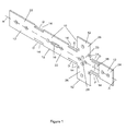
Figure 1 is a perspective exemplary view of the body of an electrical installation outline marking template according to the invention. -
Figure 2A is an exploded view of one version of a rotationally positioinable distance pole mount that can be used with the invention. -
Figure 2B is an exemplary assembled view of the distance pole mount in a first angular position. -
Figure 2C is an exemplary view of the distance pole mount ofFigures 2A and 2B rotated to a second selectable position. -
Figure 2D is an exemplary view of the distance pole mount ofFigures 2A, 2B and 2D rotated to a third selectable position. -
Figure 3A is an exemplary view of the a typical use of the electrical installation outline marking template ofFigure 1 with a distance pole mounted in the distance pole mount positioned in the first position as shown inFigure 2B . -
Figure 3B is an exemplary view of the a typical use of the electrical installation outline marking template ofFigure 1 with a distance pole mounted in the distance pole mount positioned in the third position as shown inFigure 2D , the electrical installation outline template being used inverted from the view ofFigure 3A . -
Figure 3C is an exemplary view of the electrical installation outline marking template ofFigure 1 with a distance pole mounted in the distance pole mount positioned in a parked transportable position in the second position as shown inFigure 2C . -
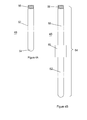
Figure 4A shows an exemplary one of many distance poles that are supplied for use with the electrical installation outline marking template. -
Figure 4B shows an example of how a lengthened distance pole of greater length can be created by collinear assembly of one or more partial distance poles. -
Figure 5 shows use of an alternative distance pole mount where no rotation is required.
and -
Figure 6 , showing an embodiment with distance markings on thetemplate 10 which can be employed to make use of the template without use of a distance pole - Attention is first drawn to
Figure 1 , a perspective exemplary view of the body of an electrical installation outline marking template according to the invention. - A first and significant difference between the present invention and the solutions provided in the prior art documents lies in the present invention comprising an
outline template 10 havingoutline sections 12 each defining the regulation shape of pattresses. In order to mark the position of aparticular outline section 12, it is simply necessary to apply theoutline template 10 to a wall and to mark around the outside of a section onto the wall. - A second significant difference between the present invention and the solutions provided in the prior art documents lies in the present invention providing
plural outline sections 12 spaced apart from one another according to the regulations, thereby obviating the need to re-measure between template uses. - A third significant difference between the present invention and the solutions provided in the prior art documents lies in the present invention providing for use of any of a plurality of distance poles that allow for rapid measurement free height positioning to meet regulations. The distance poles prevent inadvertent errors in measurements.
- The
individual outline sections 12 are separated from one another by outline separation distance D. Template voids 14 are provided betweenoutline sections 12 to permit a marking device to detail at least part of the sides of eachoutline section 12. - A
spirit level 16, viewable both from above and below, is provided affixed to theoutline template 10 and designed to allow the axis A, shown in dashed line, of theoutline template 10 to be levelled. - A distance pole
mount attachment area 18 is provide on theoutline template 10 for attachment, as later described in relation toFigure 2 , of a distance pole mount. - Drilling hole location marking points 20 are provided, though penetrating the
outline template 10, to allow marking for the location of holes used to affix a pattress. The more usual type of pattress, requires only two fixing holes, as shown inFigure 1 . It is to be appreciated that different pattress fixing hole configurations are possible within the invention, and can, include, for example, but not limited to, in addition to the drilling hole location marking points 20 shown, further drilling hole location marking points 20 proximate to each corner of theoutline sections 12 to allow fitting of four screw pattresses. - Outline
sections 12 on theoutline template 10 comprise, in the example shown inFigure 1 , two spaced dualsocket outline sections 22, a singlesocket outline section 24, that also doubles as a light switch outline section, and a cookersocket outline section 26 that also provides a further singlesocket outline section 28 spaced from the a singlesocket outline section 24 by the regulation distance. - The
outline template 10 is useable in an inverted configuration from the configuration shown inFigure 1 , otherwise shown inFigure 3B , to allow use proximate to room and outside wall corners. - While the
outline template 10, as shown inFigure 1 , is designed for use according to UK Building Regulations part M, outlinetemplates 10 for use in accordance with other regulations, for example, but not limited to, regulations in force in other countries and/or for different types of constructions all fall within the invention. In these alternative conditions, different sizes and spacing ofoutline areas 12 will be used in the invention. - Attention is next drawn to
Figure 2A , an exploded view of one version of a rotationally positioinable distance pole mount that can be mounted on the distance polemount attachment area 18 to be used with the invention. - The distance pole
mount attachment area 18 comprises arotational axle aperture 30 located in a spaced circularly symmetric relationship with threerotational detents 32 arranged equiangularly around a semicircle with therotational axle aperture 30 at their centre. Therotational detents 32 can be mere dimples or full holes through the surface of theoutline template 10 and represent, respectively, means for holding, against spring pressure, adistance pole mount 34 in an upward, downward and axial A direction. - The
distance pole mount 34 is assembled by urging thedistance pole mount 34 against spring pressure onto the polemount attachment area 18 as indicated byarrow 36 and fixing it in place with a countersunk screw or any other means that does not protrude from the rear face of the outline template and allows thedistance pole mount 34 to rotate around therotational axle aperture 30. - Attention is next drawn to
Figure 2B , an exemplary assembled view of thedistance pole mount 34 in a first angular position. Thedistance pole mount 34 is held by spring detent location in arotational detent 32 in a position where a distance pole (to be described) is held in an downward position as seen inFigures 1 and2A . - Attention is next drawn to
Figure 2C , an exemplary view of the distance pole mount ofFigures 2A and 2B rotated to a second selectable position. Thedistance pole mount 34 is rotated as indicated by firstrotary arrow 38 until it clicks into the second position with, as explained later, with the distance pole, when fitted, pointing along the axis A of theoutline template 10. - Attention is next drawn to
Figure 2D an exemplary view of the distance pole mount ofFigures 2A, 2B and 2C rotated to a third selectable position. Thedistance pole mount 34 is rotated as indicated by secondrotary arrow 40 until it clicks into the third position with, as explained later, with the distance pole, when fitted, pointing upward from of theoutline template 10 when theoutline template 10 is viewed as shown inFigure 1 . - Seen in
Figure 2D is a distancepole acceptance aperture 42 having around its periphery a distancepole engaging thread 44 that engages, as is later explained, a threaded portion of a distance pole. - It is to be appreciated that other means can be used within the invention for sleeking the rotational position of the
distance pole mount 34, including, but not limited to: use of screws and pins to secure thedistance pole mount 34 when it is in the correct position; and physical removal of the distance pole mount 34 from the outline template and replacement into a new position maintained by peg holes and the like. All that matters, according to, the invention, is that the distance pole and/or thedistance pole mount 34 be fixable in at least the first and third angular orientations relative to theoutline template 10. - Attention is next drawn to
Figure 3A , an exemplary view of the a typical use of the electrical installationoutline marking template 10 ofFigure 1 with a distance pole mounted in the distance pole mount positioned in the first position as shown inFigure 2B . - The
outline template 10 is shown in the orientation ofFigure 1 , urged flat against the vertical surface of awall 46 with adistance pole 48 mounted in thedistance pole mount 34, urged vertically against thefloor 50 beneath thewall 46 to maintain theoutline template 10 at the distance determined by thedistance pole 48, and levelled by use of thespirit level 16. - Attention is next drawn to
Figure 3B is an exemplary view of the a typical use of the electrical installationoutline marking template 10 ofFigure 1 with adistance pole 48 mounted in thedistance pole mount 34 positioned in the third position as shown inFigure 2D , the electrical installation outline template being used inverted from the view ofFigure 3A . - The
outline template 10 is here used in a horizontally flipped position compared to that shown inFigure 1 . The flippedoutline template 10 urged flat against the vertical surface of awall 46 with thedistance pole 48 mounted in thedistance pole mount 34 in the third position, urged vertically against thefloor 50 beneath thewall 46 to maintain theoutline template 10 at the distance determined by thedistance pole 48, and levelled by use of thespirit level 16, which is visible both from above and below. - Attention is next drawn to
Figure 3C , an exemplary view of the electrical installation outline marking template ofFigure 1 with adistance pole 48 mounted in thedistance pole mount 34 positioned in a parked transportable position in the second position as shown inFigure 2C . - The
distance pole 48 lies parallel to the axis A of theoutline template 10 and allows easy transportation of the totally assembled outline template10 when it is moved from position to position in a workplace with a view to performing marking operations for pattresses at the same repeated height from the floor. Transportation is eased by the general reduction in the outside dimensions of the totally assembled outline template, and also by thedistance pole 48 and theoutline template 10 forming a hook with thedistance pole mount 34 at its apex thereby permitting the totally assembleoutline template 10 48 to be hung over edges in work trousers, overalls, bags and backpacks. - Attention is next drawn to
Figure 4A showing an exemplary one of many distance poles that are supplied for use with the electrical installation outline marking template. - An outline template kit is supplied containing an
outline template 10 and a plurality ofdistance poles 48 that can be use with theoutline template 10 to position theoutline template 10 at any one of a plurality of regulation heights above thefloor 50. - A
distance pole 48 comprises acylindrical body 52 with a preferably hemispherical shapedend 54 that, in use, is urged against thefloor 50 to be able to rock, thereby allowing the outline template to be levelled using thespirit level 16. - The
cylindrical body 52 has, at its other end, a threadedportion 56 that, in use, screws into the distancepole acceptance aperture 42 using the distancepole engaging thread 44 as shown inFigure 2D . - Attention is next drawn to
Figure 4B showing an example of how a lengthened distance pole of greater length can be created by collinear assembly of one or more partial distance poles. - A
partial distance pole 58 having threadedportions 56 at both ends screws into one side of acollar 60. Aterminal distance pole 62 having the same general features as thedistance pole 48 shown inFigure 4A screws into the other side of thecollar 60 to form a lengtheneddistance pole 64. Even longer lengtheneddistance poles 64 can be formed by assembling pluralpartial distance pole 58 andcollar 60 pairs ahead of aterminal distance pole 62. Assembly of lengthened distance poles is used to minimize the size of thetemplate 10 kit to allow it easily to be accommodated in a container even though some of the regulation heights exceed the dimensions of the container. - Attention is next drawn to
Figure 5 showing use of an alternativedistance pole mount 34A where no rotation is required. The alternativedistance pole mount 34A has six faces. The alternativedistance pole mount 34A is generally cuboid in shape and rigidly fixed to the distance polemount attachment area 18. The alternativedistance pole mount 34A is provided with three alternative distancepole acceptance apertures 42A each with alternative distancepole engaging threads 44A on three faces thereof with two of the of the alternative distancepole acceptances apertures 42A being aligned on opposite faces to allow adistance pole 48. Thedistance pole 48 in use can be screwed into and removed from the three alternative distancepole acceptance aperture 42A to achieve the configurations shown inFigures 3A to 3C . - Attention is finally drawn to
Figure 6 , showing an embodiment with distance markings on thetemplate 10 which can be employed to make use of the template without use of adistance pole 48. The distance markings are printed upon the template together with an associated legend (not shown) indication the purpose of each of the markings. - A marking
base line 66 is provided by a measuringend 68 of thetemplate 10. In vertical use, the measuringend 68 is placed flat against the floor or desk/table surface to position the template in a vertical orientation with the markingbase line 66 in a horizontal position. In horizontal use the measuringend 68 is placed against a wall edge or corner, or against the edge of a socket, so that the markingbase line 66 is in a vertical position. - A first distance marking 70 is provided 50 mm away from marking
base line 66 indicative of the distance that should be provided between adjacent sockets. - A second distance marking 72 is provided 113.5 mm away from marking
base line 66 indicative of the minimum distance that socket outlets should be above work surfaces in kitchens and offices. - It should be noted that additions to existing sockets can remain at existing heights.
- A
secondary measurement baseline 74 is provided at the distal end of theoutline section 12 from the makingbase line 68. A third distance marking is provided 150 mm away from thesecondary measurement baseline 74 indicative of the minimum spacing allowed between nominal voltage socket outlets and low voltage socket outlets. - Finally, a fourth distance marking 78 is provided 450 mm away from the marking
base line 66 indicating that sockets in newbuilds should be positioned 450 mm from finished floor levels. - In use, the
template 10 measuring end 68 (or the distal edge of the outline section 12) is placed on or against the boundary from which measurement is to be made and one or more marks made at the appropriate using a marking instriment at the indicated point or distance. - When a pattress is to be installed, the lower edge of the pattress is positioned level with the marked line,
- The
markings 70 72 74 76 78 can also be used properly to space light switch and socket pattresses away from wall edges, wall corners, and door uprights. - In different countries, the
markings 70 7274c76 78 may be differently applied in accord with local regulations and custom. - The omission of the
distance pole 48 while still providing utility from themarkings 70 72 7476 78 provides the advantage of rendering thetemplate 10 one-piece, easily transportable and not requiring a container for its storage and/or transport. - The
overall outline template 10 and its associated parts can be made using plastic, metal, wood, or any combination thereof.Distance pole 48 insertion or removal can be accomplished not only withscrew threads 56 4242A 44 44A but can also employ, for example, but not limited to; screw threads; click fits; and retentions pins. - The invention if further clarified and defined by the appended Claims.
Claims (12)
- An apparatus for marking the position of one an electrical pattress on a wall, comprising:a marking template, allowing marking of the peripheral dimensions of an electrical pattress and positionable on a wall at a desired regulation height;measuring means operable to be placed against a reference surface and adapted to provide positioning for the template;anda spirit level, affixed to the template and operable to indicate when the template is horizontal;wherethe template is an outline template adapted for marking around the outside thereof.
- The apparatus of Claim 1, wherein the template comprises a plurality of outline sections where:each outline section provides for marking of the position of an individual electrical pattress;andadjacent outline sections are spaced apart by a distance allowing installed electrical pattresses to be at a regulation horizontal distance apart.
- An apparatus according to any of the preceding claims wherein the measuring means comprises a distance pole having first and second ends, the positioning pole being affixable to the template by the first end and operable, when the second end is placed in contact the floor beneath a wall, to cause the template to be at the desired height.
- The apparatus of Claim 3 wherein the distance pole is one of a plurality of distance poles, where
each distance pole has a respective different length from others of the plurality of distance pole;
and
each distance pole, when used with the template, allows the template to be at a respective different regulation height. - The apparatus of any of the preceding Claims wherein, when a distance pole exceeds a predetermined length, the distance pole is assembled using one or more partial distance poles joined co-linearly with a terminal distance pole.
- The apparatus of Claim 4 or 5 wherein the plurality of distance poles comprises distance poles for positioning the template at each regulation height laid down in the regulations.
- The apparatus of any one of claims 3 to 6 comprising a distance pole mount operable to support the distance pole in two positions:a first position on a first side of the template for use in supporting the template in a first horizontal orientation;anda second position on a second side of the template for use in supporting the template in a second horizontal orientation;wherethe second horizontal orientation is horizontally flipped end to end with respect to the first horizontal orientation.
- The apparatus of claim 7 wherein the distance pole mount is further operable to support the distance pole, in a third position, where the distance pole is positioned along the axis of the template.
- The apparatus of Claim 7 or 8 wherein the distance pole is affixable to the distance pole mount using a screw thread, and the distance pole mount comprises screw threads useable to support the distance pole in each of the first, second and third positions.
- The apparatus of Claim 7 or 8 wherein the distance pole mount comprises a click stop mechanism useable to allow the distance pole in any one of the first, second and third positions.
- An apparatus, according to Claim 1 or Claim 2, wherein the measuring means comprises:a plurality of markings provided on the template and spaced away a corresponding plurality of regulation distances away one or more references edges on the template;and wherein,the template is positionable for an edge of a marking guide to be aligned with marks made on a wall corresponding to a selected distance prior to marking around the outside of a pattress.
- An apparatus substantially as described with reference to the appended drawings.
Priority Applications (1)
| Application Number | Priority Date | Filing Date | Title |
|---|---|---|---|
| EP12196886.1A EP2744055A1 (en) | 2012-12-13 | 2012-12-13 | Electrical installation marking aid |
Applications Claiming Priority (1)
| Application Number | Priority Date | Filing Date | Title |
|---|---|---|---|
| EP12196886.1A EP2744055A1 (en) | 2012-12-13 | 2012-12-13 | Electrical installation marking aid |
Publications (1)
| Publication Number | Publication Date |
|---|---|
| EP2744055A1 true EP2744055A1 (en) | 2014-06-18 |
Family
ID=47623820
Family Applications (1)
| Application Number | Title | Priority Date | Filing Date |
|---|---|---|---|
| EP12196886.1A Withdrawn EP2744055A1 (en) | 2012-12-13 | 2012-12-13 | Electrical installation marking aid |
Country Status (1)
| Country | Link |
|---|---|
| EP (1) | EP2744055A1 (en) |
Cited By (4)
| Publication number | Priority date | Publication date | Assignee | Title |
|---|---|---|---|---|
| GB2552951A (en) * | 2016-08-10 | 2018-02-21 | Jim Maidement | Electrical socket marker template |
| GB2585347A (en) * | 2019-04-30 | 2021-01-13 | Circle Box Ltd | Back box installation device |
| DE202021102215U1 (en) | 2021-04-26 | 2022-07-27 | Stefan Kolitsch | Spirit level with marking instrument |
| DE102021107367B3 (en) | 2021-03-24 | 2022-08-18 | Stefan Kolitsch | Additional device for a spirit level |
Citations (12)
| Publication number | Priority date | Publication date | Assignee | Title |
|---|---|---|---|---|
| DE8214744U1 (en) * | 1982-05-21 | 1982-08-12 | Leist, Rudolf, 6721 Schwegenheim | Template for marking places |
| DE8315615U1 (en) * | 1983-05-27 | 1983-10-27 | Rosenberger, Norbert, 8752 Blankenbach | Marking device for installation boxes in electrical installations |
| US4793069A (en) * | 1987-06-15 | 1988-12-27 | Mcdowell Kenneth H | Device for installing electric outlet boxes |
| GB2248035A (en) | 1990-09-20 | 1992-03-25 | George William Knox | Template for use in electrical socket or switch box installation |
| US5222303A (en) | 1991-12-19 | 1993-06-29 | Jardine Stuart A | Template for marking the location of junction boxes |
| DE19523994A1 (en) * | 1995-06-30 | 1997-01-02 | Peter Sturm | Template for marking out positions where electric socket and switch installation outlets are to be mounted |
| DE29713530U1 (en) * | 1997-07-30 | 1997-09-25 | Braun Konrad | Scribing template for electrical installation boxes |
| US5860219A (en) | 1997-03-19 | 1999-01-19 | Wilkinson; Carl E. | Templates for positioning outlet boxes |
| GB2364950A (en) | 2000-07-26 | 2002-02-13 | Graham Francis Pimbley | Template for use in electrical switch or socket box installation |
| US6434848B1 (en) * | 1999-02-05 | 2002-08-20 | Kyle L. Gordon | Template for scribbing electrical box openings for old work |
| US20040040167A1 (en) * | 2002-09-04 | 2004-03-04 | Hall Matthew R. | Electric junction box template |
| GB2401811A (en) * | 2003-05-23 | 2004-11-24 | Stuart Dennis Mckeith | A device to aid wall mounting of electrical wall boxes |
-
2012
- 2012-12-13 EP EP12196886.1A patent/EP2744055A1/en not_active Withdrawn
Patent Citations (12)
| Publication number | Priority date | Publication date | Assignee | Title |
|---|---|---|---|---|
| DE8214744U1 (en) * | 1982-05-21 | 1982-08-12 | Leist, Rudolf, 6721 Schwegenheim | Template for marking places |
| DE8315615U1 (en) * | 1983-05-27 | 1983-10-27 | Rosenberger, Norbert, 8752 Blankenbach | Marking device for installation boxes in electrical installations |
| US4793069A (en) * | 1987-06-15 | 1988-12-27 | Mcdowell Kenneth H | Device for installing electric outlet boxes |
| GB2248035A (en) | 1990-09-20 | 1992-03-25 | George William Knox | Template for use in electrical socket or switch box installation |
| US5222303A (en) | 1991-12-19 | 1993-06-29 | Jardine Stuart A | Template for marking the location of junction boxes |
| DE19523994A1 (en) * | 1995-06-30 | 1997-01-02 | Peter Sturm | Template for marking out positions where electric socket and switch installation outlets are to be mounted |
| US5860219A (en) | 1997-03-19 | 1999-01-19 | Wilkinson; Carl E. | Templates for positioning outlet boxes |
| DE29713530U1 (en) * | 1997-07-30 | 1997-09-25 | Braun Konrad | Scribing template for electrical installation boxes |
| US6434848B1 (en) * | 1999-02-05 | 2002-08-20 | Kyle L. Gordon | Template for scribbing electrical box openings for old work |
| GB2364950A (en) | 2000-07-26 | 2002-02-13 | Graham Francis Pimbley | Template for use in electrical switch or socket box installation |
| US20040040167A1 (en) * | 2002-09-04 | 2004-03-04 | Hall Matthew R. | Electric junction box template |
| GB2401811A (en) * | 2003-05-23 | 2004-11-24 | Stuart Dennis Mckeith | A device to aid wall mounting of electrical wall boxes |
Cited By (5)
| Publication number | Priority date | Publication date | Assignee | Title |
|---|---|---|---|---|
| GB2552951A (en) * | 2016-08-10 | 2018-02-21 | Jim Maidement | Electrical socket marker template |
| GB2585347A (en) * | 2019-04-30 | 2021-01-13 | Circle Box Ltd | Back box installation device |
| DE102021107367B3 (en) | 2021-03-24 | 2022-08-18 | Stefan Kolitsch | Additional device for a spirit level |
| WO2022199748A1 (en) | 2021-03-24 | 2022-09-29 | Stefan Kolitsch | Add-on for a spirit level |
| DE202021102215U1 (en) | 2021-04-26 | 2022-07-27 | Stefan Kolitsch | Spirit level with marking instrument |
Similar Documents
| Publication | Publication Date | Title |
|---|---|---|
| US5222303A (en) | Template for marking the location of junction boxes | |
| US5860219A (en) | Templates for positioning outlet boxes | |
| US8099878B2 (en) | Electrical box template | |
| US20100095543A1 (en) | Tool for Installing an Electrical Outlet Box | |
| EP2744055A1 (en) | Electrical installation marking aid | |
| US20150136437A1 (en) | Efficient installation electrical hardware system and method of use | |
| US20050060904A1 (en) | Template system for locating and cutting wall or ceiling openings | |
| US5615490A (en) | Receptacle locator | |
| US8015719B2 (en) | Electricians square | |
| US20120096724A1 (en) | Cut out template | |
| US10084298B2 (en) | Self-measuring wall box bracket | |
| US10193318B1 (en) | Efficient installation electrical hardware system and method of use | |
| US4285135A (en) | Panel cutting guide | |
| US11159004B2 (en) | Adjustable recessed box | |
| US10807406B2 (en) | Old work box device | |
| US20090277029A1 (en) | Electrical box template | |
| US20040083617A1 (en) | Method and structure for installing an electrical device box | |
| US10714919B2 (en) | Wallbox installation tool | |
| US8943704B1 (en) | Apparatus for locating fixture boxes and the like | |
| US20040035015A1 (en) | Electrician's measurement apparatus and method of use | |
| GB2496155A (en) | Electrical Installation Marking Aid | |
| US10260245B2 (en) | Tool for marking and measuring struts for construction | |
| AU2008291435A1 (en) | Installation cabinet and method for producing a place for an installation cabinet | |
| US6546641B1 (en) | Device for guiding the cutting of an opening in a wall | |
| EP2597743B1 (en) | An installation box for mounting an electrical installation device |
Legal Events
| Date | Code | Title | Description |
|---|---|---|---|
| PUAI | Public reference made under article 153(3) epc to a published international application that has entered the european phase |
Free format text: ORIGINAL CODE: 0009012 |
|
| 17P | Request for examination filed |
Effective date: 20121213 |
|
| AK | Designated contracting states |
Kind code of ref document: A1 Designated state(s): AL AT BE BG CH CY CZ DE DK EE ES FI FR GB GR HR HU IE IS IT LI LT LU LV MC MK MT NL NO PL PT RO RS SE SI SK SM TR |
|
| AX | Request for extension of the european patent |
Extension state: BA ME |
|
| R17P | Request for examination filed (corrected) |
Effective date: 20141215 |
|
| 17Q | First examination report despatched |
Effective date: 20170310 |
|
| STAA | Information on the status of an ep patent application or granted ep patent |
Free format text: STATUS: THE APPLICATION IS DEEMED TO BE WITHDRAWN |
|
| 18D | Application deemed to be withdrawn |
Effective date: 20171027 |