EP2753100A1 - Hearing aid component with earwax filter - Google Patents
Hearing aid component with earwax filter Download PDFInfo
- Publication number
- EP2753100A1 EP2753100A1 EP13150405.2A EP13150405A EP2753100A1 EP 2753100 A1 EP2753100 A1 EP 2753100A1 EP 13150405 A EP13150405 A EP 13150405A EP 2753100 A1 EP2753100 A1 EP 2753100A1
- Authority
- EP
- European Patent Office
- Prior art keywords
- sound inlet
- sound
- hearing aid
- earwax
- inlet opening
- Prior art date
- Legal status (The legal status is an assumption and is not a legal conclusion. Google has not performed a legal analysis and makes no representation as to the accuracy of the status listed.)
- Granted
Links
Images


Classifications
-
- H—ELECTRICITY
- H04—ELECTRIC COMMUNICATION TECHNIQUE
- H04R—LOUDSPEAKERS, MICROPHONES, GRAMOPHONE PICK-UPS OR LIKE ACOUSTIC ELECTROMECHANICAL TRANSDUCERS; DEAF-AID SETS; PUBLIC ADDRESS SYSTEMS
- H04R25/00—Deaf-aid sets, i.e. electro-acoustic or electro-mechanical hearing aids; Electric tinnitus maskers providing an auditory perception
- H04R25/65—Housing parts, e.g. shells, tips or moulds, or their manufacture
- H04R25/652—Ear tips; Ear moulds
- H04R25/654—Ear wax retarders
-
- H—ELECTRICITY
- H04—ELECTRIC COMMUNICATION TECHNIQUE
- H04R—LOUDSPEAKERS, MICROPHONES, GRAMOPHONE PICK-UPS OR LIKE ACOUSTIC ELECTROMECHANICAL TRANSDUCERS; DEAF-AID SETS; PUBLIC ADDRESS SYSTEMS
- H04R25/00—Deaf-aid sets, i.e. electro-acoustic or electro-mechanical hearing aids; Electric tinnitus maskers providing an auditory perception
- H04R25/60—Mounting or interconnection of hearing aid parts, e.g. inside tips, housings or to ossicles
Definitions
- the invention relates to a hearing aid component with an earwax (cerumen) filter and an earwax filter for placement in an opening of a hearing aid component.
- Earwax filters are used to prevent earwax (earwax) from entering openings, such as sound openings of a hearing aid component.
- earwax filters are made replaceable so that a used and potentially clogged earwax filter can be replaced by a new and clean one.
- handling tools are provided that help in removing a used earwax filter and in inserting a new earwax filter.
- earwax filter dispensers are known.
- Sound emitted by a hearing aid travels from a hearing aid's output transducer (receiver , loudspeaker) to a hearing aid sound outlet opening, where it has to pass the earwax filter.
- proximal parts along the sound path that are closer to the receiver
- distal parts that are closer to a user's tympanic membrane (such as the earwax filter) are called “distal”.
- Ambient sound entering the hearing aid first passes a sound inlet opening and then travels to a pick-up transducer for converting sound waves into electric signals, e.g. a microphone.
- a pick-up transducer for converting sound waves into electric signals, e.g. a microphone.
- parts along the sound path that are closer to an ambient sound source are called “proximal”
- parts that are closer to a hearing aid component's pick-up transducer such as a microphone
- Prior art earwax filters and handing tools are inter alia disclosed in EP 1 439 731 B1 , US 6,795,562 B1 , DE 202 08 601 U1 , WO 03/067926 A3, WO 00/03561 A1 , EP 0 724 377 , US 5,278,360 A , US 4,972,488 A , DE 89 13 743 U1 and US 4,870,689 A .
- the invention aims for an effective, easy to handle earwax filter.
- this aim is achieved by a combination of a hearing aid component with earwax filter.
- the hearing aid component has a sound inlet opening that has at least two sound inlet portions having different diameters and being displaced with respect to each other in a longitudinal direction of the sound inlet opening so that the sound inlet opening narrows towards the interior of the hearing aid component, resulting in that the more proximal sound inlet portion has a relatively larger diameter and the more distal sound inlet portion has a relatively smaller diameter.
- the earwax filter is placed in said sound inlet opening and comprises:
- the sound inlet opening of the hearing aid component can be arranged in a faceplate of the hearing aid component.
- the particular shape of the sound inlet opening with its two portions with different diameters together with the sound path defined by the particular geometry of the earwax filter result in a capillary trap that prevents earwax from creeping into the sound inlet.
- the capillary trap is essentially caused by the right angle between a surface of the sound inlet opening and a surface of the earwax filter.
- the oily substances of the earwax have a tendency to creep along capillary paths, but here the large angle between the two surfaces blocks further advance of the fluid.
- the peripheral edges are part of an outwardly facing circumferential bead that surrounds the cap and has a diameter that is larger than the perimeter of the cap along which the sound inlets are arranged.
- the circumferential bead radially extends beyond a circumferential side wall of the cap.
- the circumferential bead is recessed in the sound inlet portion with a relatively larger diameter.
- a small annular groove is created between a circumferential wall of the outer sound inlet portion and the circumferential outer wall of the cap.
- the circumferential bead has an inner contact surface that contacts a radially extending wall portion of the sound inlet opening that is present between a proximal sound inlet portion with a relatively larger diameter and the distal sound inlet portion with a relatively smaller diameter. This difference in diameters results in a kind of step which leads to the radially extending wall portion of the sound inlet opening.
- the inner contact surface of the circumferential bead abuts the radially extending wall portion of the sound inlet opening when the earwax filter if fully inserted into the sound inlet opening.
- the inner contact surface of the earwax filter and the radially extending wall portion of the sound inlet define how deep the earwax filter can be inserted into the sound inlet opening.
- the circumferential bead has an inner circumferential wall that extends in a direction transverse to the radially extending wall portion of the sound inlet opening and defines an at least nearly a right angle between the radially extending wall portion and the inner circumferential wall. This angle is an essential feature to keep earwax from creeping further into the sound inlet opening, because this sharp angle creates a capillary trap.
- the circumferential bead is connected to the cap by axially and radially extending ribs, wherein each rib is arranged between two neighboring sound inlets.
- Each rib preferably has an inner edge facing the radially extending wall portion of the sound inlet opening. It is preferred if the inner edge of each rib and the inner contact surface of the circumferential bead are offset with respect to each other so as to leave a gap between each inner edge of each rib and the radially extending wall portion of the sound inlet opening when the inner contact surface of the circumferential bead contacts the radially extending wall portion. This gap causes a widening of the sound inlets by way of some sort of undercut and further helps to prevent earwax from creeping into the sound inlet opening. Therefore, the gap is not just a marginal gap.
- the number of ribs is preferably between 5 and 11, e.g. 9.
- the stem of the earwax filter that extends into the more distal portion of the sound inlet opening preferably has a blind hole that is open towards the outward facing side of the cap and that is configured to receive a tip of a handling tool.
- a tip of a handling tool can be inserted into the blind hole for handling the earwax filter.
- a snap bead is formed on the circumferential wall of the blind hole which allows a snap-fit connection with the handling tool.
- the earwax filter is an interchangeable unit which has small openings (sound inlets) for the sound to enter and which can be replaced when necessary.
- the unit preferably is hydrophobic coated and the path from each sound inlet to transducer is z-shaped to complicate the eventual travel of earwax or the like.
- a sealing feature hinders earwax or the like from travelling at the interface between the unit and the other parts of the hearing instrument, which furthermore bring out eventual earwax or the like when the unit is removed.
- a secondary protection feature follow the sealing feature and take advantage of capillary forces by having a large volume after a ever small volume, hence prevent further travel of earwax or the like.
- This solution is preferred due to the application of various features which work side by side to protect against earwax or the like, e.g. hydrophobic coating which rule out travel of earwax on the surfaces, z-shaped path from sound inlet to end of filter, double protection at the interface between the filter and the mounting hole, self cleaning function, and it integrated removal feature.
- various features which work side by side to protect against earwax or the like, e.g. hydrophobic coating which rule out travel of earwax on the surfaces, z-shaped path from sound inlet to end of filter, double protection at the interface between the filter and the mounting hole, self cleaning function, and it integrated removal feature.
- the wax protection filter is made up by a cylindrical shape with sound inlets positioned around the side of the cylinder, which is hydrophobic coated.
- the earwax filter is shaped to be mounted in a counter sunk hole of the sound inlet opening. When the earwax filter is mounted the sound inlets will be positioned so that earwax can not enter directly, the hydrophobic coating contribute to earwax not entering through the sound inlets.
- the peripheral outer edge of the outward-facing circumferential bead provides fixation of the filter through a press fit between the earwax filter and the sound inlet opening.
- the filter is removed using a tool with a tip which snaps onto the earwax filter at the central blind hole.
- This blind hole features an under-cut feature which along with the tool make up the snap functionality.
- sound inlet opening 10 has a proximal (outer) portion 14 with a larger diameter and a more distal portion 14 with a smaller diameter. Between the proximal portion 12 of the sound inlet opening 10 and the distal portion 14 of the sound inlet opening 10, a radially extending wall portion 16 of the sound inlet opening exists due to the fact that the larger diameter proximal portion 12 of the sound inlet opening and the smaller diameter distal portion 14 of the sound inlet opening 10 define a step.
- the earwax filter 20 inserted in sound inlet opening 10 contacts and abuts sound inlet opening 10 on a circumferential wall 18 of the proximal portion 12 of the sound inlet opening 10 and at the radially extending wall portion 16.
- the earwax filter 20 has two surfaces that abut the sound inlet opening, namely a peripheral edge 22 and an inner contact surface 24 of an outward facing circumferential bead 26 that surrounds a cap 28 of earwax filter 20.
- the diameter of the perimeter of the cap 28 along which the sound inlets 30 are arranged is smaller than the diameter of the peripheral edge 22 of the circumferential bead 26 and thus smaller than the diameter of the proximal (outer) sound inlet opening portion 12.
- the perimeter of the cap 28 along which the sound inlets 30 are arranged is indicated in figure 2 by a dash-dotted line.
- a longitudinal extension of the circumferential bead 26 is smaller than a longitudinal extension of the proximal sound inlet opening portion 12 - if measured along the longitudinal axis of sound inlet opening 10. Therefore, the circumferential bead 26 is recessed in the proximal sound inlet opening portion 12 and a groove 32 is created around the perimeter of the cap of the earwax filter.
- the circumferential bead 26 has an inner circumferential wall 34 that extends in a direction transverse to the radially extending wall portion 16 of the sound inlet opening 10 and defines an at least nearly right angle between the radially extending wall portion 16 and the inner circumferential wall 34. This angle is an essential feature to keep earwax from creeping further into the sound inlet opening, because this sharp angle creates a capillary trap.
- the circumferential bead 26 is connected to the cap 28 by axially and radially extending ribs 36.
- Each rib 36 is arranged between two neighboring sound inlets 30.
- Each rib has an inner edge 38 facing the radially extending wall portion 16 of the sound inlet opening 10.
- the inner edge 38 of each rib 36 and the inner contact surface 24 of the circumferential bead 26 are offset with respect to each other so as to leave a gap 40 between each inner edge 38 of each rib 36 and the radially extending wall portion 16 of the sound inlet opening when the inner contact surface 24 of the circumferential bead 26 contacts the radially extending wall portion 16.
- This gap 40 causes a widening of the sound inlets 30 by way of some sort of undercut and further helps to prevent earwax from creeping into the sound inlet opening. Therefore, the gap 40 is not just a marginal gap.
- the earwax filter 20 has a stem 42 that extends into the distal portion 14 of the sound inlet opening 10 while leaving an annular gap 44 between an inner circumferential wall 46 of the distal portion 14 and an outer circumferential wall 48 of the stem 42 thus defining a portion of a sound path along earwax filter 20. Due to the stepped shape of the sound inlet opening 10 and the shape of the earwax filter 20, a z-shaped sound path is defined that helps to prevent earwax from entering into sound inlet opening 10.
- the stem 42 has a centrally arranged blind hole 50 that is open towards the outward facing side of the cap 28.
- the blind hole 50 is configured to receive a tip 52 (see figure 9 ) of a handling tool.
- the tip 52 of a handling tool can be inserted into the blind hole 50 for handling the earwax filter.
- a snap bead 54 is formed on the circumferential wall 56 of the blind hole which allows a snap-fit connection with the handling tool.
Abstract

Description
- The invention relates to a hearing aid component with an earwax (cerumen) filter and an earwax filter for placement in an opening of a hearing aid component.
- Earwax filters are used to prevent earwax (earwax) from entering openings, such as sound openings of a hearing aid component. Typically, earwax filters are made replaceable so that a used and potentially clogged earwax filter can be replaced by a new and clean one. To do so, handling tools are provided that help in removing a used earwax filter and in inserting a new earwax filter. To allow for easy carrying of plurality of earwax filters, earwax filter dispensers are known.
- Sound emitted by a hearing aid travels from a hearing aid's output transducer (receiver , loudspeaker) to a hearing aid sound outlet opening, where it has to pass the earwax filter. For the purpose of this disclosure, parts along the sound path that are closer to the receiver are called "proximal", and parts that are closer to a user's tympanic membrane (such as the earwax filter) are called "distal".
- Ambient sound entering the hearing aid first passes a sound inlet opening and then travels to a pick-up transducer for converting sound waves into electric signals, e.g. a microphone. For the purpose of this disclosure, parts along the sound path that are closer to an ambient sound source are called "proximal", and parts that are closer to a hearing aid component's pick-up transducer (such as a microphone) are called "distal".
- Penetration of earwax and the like tend to be a major reason to failing hearing instruments. To improve the service rate, life time and reliability of hearing instruments, a system which prevents earwax from entering the hearing instrument and reaching the transducers is essential. The system shall not influence the performance of the hearing instrument.
- Prior art earwax filters and handing tools are inter alia disclosed in
EP 1 439 731 B1 ,US 6,795,562 B1 ,DE 202 08 601 U1 ,WO 03/067926 WO 00/03561 A1 EP 0 724 377 ,US 5,278,360 A ,US 4,972,488 A ,DE 89 13 743 U1 andUS 4,870,689 A . - The invention aims for an effective, easy to handle earwax filter.
- According to the invention, this aim is achieved by a combination of a hearing aid component with earwax filter. The hearing aid component has a sound inlet opening that has at least two sound inlet portions having different diameters and being displaced with respect to each other in a longitudinal direction of the sound inlet opening so that the sound inlet opening narrows towards the interior of the hearing aid component, resulting in that the more proximal sound inlet portion has a relatively larger diameter and the more distal sound inlet portion has a relatively smaller diameter. The earwax filter is placed in said sound inlet opening and comprises:
- A cap with a an outward-facing and an inward-facing side and a peripheral edge, wherein the inward-facing side faces the hearing aid and wherein the peripheral edge is force-fitted into the sound inlet portion with the relatively larger diameter;
- a stem protruding into the sound inlet portion with the relatively smaller diameter, wherein the stem has a proximal end connected to the cap, and a distal end that has a diameter that is smaller than the diameter of the sound inlet portion with the relatively smaller diameter, so that an annular gap remains between the stem and the sound inlet portion with the relatively smaller diameter,
- wherein the cap has a plurality of sound inlets arranged along the periphery of the cap, wherein the sound inlets are shaped so as to allow ambient sound passing into the annular gap, wherein the sound inlets are arranged along a perimeter.
- The sound inlet opening of the hearing aid component can be arranged in a faceplate of the hearing aid component.
- The particular shape of the sound inlet opening with its two portions with different diameters together with the sound path defined by the particular geometry of the earwax filter result in a capillary trap that prevents earwax from creeping into the sound inlet.
- The capillary trap is essentially caused by the right angle between a surface of the sound inlet opening and a surface of the earwax filter. The oily substances of the earwax have a tendency to creep along capillary paths, but here the large angle between the two surfaces blocks further advance of the fluid.
- Preferably, the peripheral edges are part of an outwardly facing circumferential bead that surrounds the cap and has a diameter that is larger than the perimeter of the cap along which the sound inlets are arranged. In other words: The circumferential bead radially extends beyond a circumferential side wall of the cap. According to a further preferred embodiment, the circumferential bead is recessed in the sound inlet portion with a relatively larger diameter. Thus, a small annular groove is created between a circumferential wall of the outer sound inlet portion and the circumferential outer wall of the cap.
- It is preferred that the circumferential bead has an inner contact surface that contacts a radially extending wall portion of the sound inlet opening that is present between a proximal sound inlet portion with a relatively larger diameter and the distal sound inlet portion with a relatively smaller diameter. This difference in diameters results in a kind of step which leads to the radially extending wall portion of the sound inlet opening. The inner contact surface of the circumferential bead abuts the radially extending wall portion of the sound inlet opening when the earwax filter if fully inserted into the sound inlet opening. Thus, the inner contact surface of the earwax filter and the radially extending wall portion of the sound inlet define how deep the earwax filter can be inserted into the sound inlet opening.
- It is further preferred when the circumferential bead has an inner circumferential wall that extends in a direction transverse to the radially extending wall portion of the sound inlet opening and defines an at least nearly a right angle between the radially extending wall portion and the inner circumferential wall. This angle is an essential feature to keep earwax from creeping further into the sound inlet opening, because this sharp angle creates a capillary trap.
- Preferably, the circumferential bead is connected to the cap by axially and radially extending ribs, wherein each rib is arranged between two neighboring sound inlets.
- Each rib preferably has an inner edge facing the radially extending wall portion of the sound inlet opening. It is preferred if the inner edge of each rib and the inner contact surface of the circumferential bead are offset with respect to each other so as to leave a gap between each inner edge of each rib and the radially extending wall portion of the sound inlet opening when the inner contact surface of the circumferential bead contacts the radially extending wall portion. This gap causes a widening of the sound inlets by way of some sort of undercut and further helps to prevent earwax from creeping into the sound inlet opening. Therefore, the gap is not just a marginal gap.
- The number of ribs is preferably between 5 and 11, e.g. 9.
- The stem of the earwax filter that extends into the more distal portion of the sound inlet opening preferably has a blind hole that is open towards the outward facing side of the cap and that is configured to receive a tip of a handling tool. Thus, a tip of a handling tool can be inserted into the blind hole for handling the earwax filter.
- In order to prevent the earwax filter from falling off the handling tool during handling, a snap bead is formed on the circumferential wall of the blind hole which allows a snap-fit connection with the handling tool.
- In its preferred embodiment, the earwax filter is an interchangeable unit which has small openings (sound inlets) for the sound to enter and which can be replaced when necessary. To prevent penetration of cerumen through the sound inlets the unit preferably is hydrophobic coated and the path from each sound inlet to transducer is z-shaped to complicate the eventual travel of earwax or the like. A sealing feature hinders earwax or the like from travelling at the interface between the unit and the other parts of the hearing instrument, which furthermore bring out eventual earwax or the like when the unit is removed. A secondary protection feature follow the sealing feature and take advantage of capillary forces by having a large volume after a ever small volume, hence prevent further travel of earwax or the like.
- This solution is preferred due to the application of various features which work side by side to protect against earwax or the like, e.g. hydrophobic coating which rule out travel of earwax on the surfaces, z-shaped path from sound inlet to end of filter, double protection at the interface between the filter and the mounting hole, self cleaning function, and it integrated removal feature.
- The wax protection filter is made up by a cylindrical shape with sound inlets positioned around the side of the cylinder, which is hydrophobic coated. The earwax filter is shaped to be mounted in a counter sunk hole of the sound inlet opening. When the earwax filter is mounted the sound inlets will be positioned so that earwax can not enter directly, the hydrophobic coating contribute to earwax not entering through the sound inlets.
- Two features provide protection against earwax:
- 1.) An outward-facing circumferential bead defining the peripheral outer edge of the earwax filter provides a sealing between the earwax filter and the circumferential wall of the sound inlet opening. When the earwax filter is pulled out of the sound inlet opening in which it is mounted, the peripheral edge of the circumferential bead will sweep the wall circumferential of the sound inlet opening, hence bringing out eventual earwax.
- 2.) At the interface between the earwax filter and a radially extending wall of the sound inlet opening the design takes advantage of capillary forces to keep earwax out. This is achieved by a narrow passage which ends in a much larger volume. Furthermore is the path from sound inlets to the distal end of the earwax filter, when mounted in the sound inlet opening, not direct and straight but z-shaped.
- The peripheral outer edge of the outward-facing circumferential bead provides fixation of the filter through a press fit between the earwax filter and the sound inlet opening. The filter is removed using a tool with a tip which snaps onto the earwax filter at the central blind hole. This blind hole features an under-cut feature which along with the tool make up the snap functionality.
- The invention shall now be described in more detail by way of example with respect to the attached Figures. In the Figures:
- Fig. 1
- is a cross-sectional view of a sound inlet opening and an earwax filter inserted therein;
- Fig. 2
- is a perspective representation of the earwax filter if viewed from the outside;
- Fig. 3
- is a perspective representation of the earwax filter as seen from the outside;
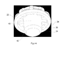
- Fig. 4
- is a perspective representation of the earwax filter as seen from the inner side;
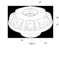
- Fig. 5
- is a side elevational view of the earwax filter;
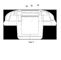
- Fig. 6
- is a cross-sectional view of the earwax filter alone;
- Fig. 7
- is a top-plane view on the earwax filter;
- Fig. 8
- is a bottom-plane view of the earwax filter;
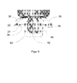
- Fig. 9
- is a partially cross-sectional representation of a tip of a handling tool interacting with the earwax filter;
- Fig. 10
- is a partially cross-sectional view of a handling tool, an earwax filter and a sound inlet opening;
- Fig. 11
- is a partially cross-sectional view of a sound inlet opening and an earwax filter inserted therein;
- Fig. 12
- is a further partially cross-sectional view of a sound inlet opening and an earwax filter inserted therein;
- As can be taken from
Fig. 1 ,sound inlet opening 10 has a proximal (outer)portion 14 with a larger diameter and a moredistal portion 14 with a smaller diameter. Between theproximal portion 12 of thesound inlet opening 10 and thedistal portion 14 of thesound inlet opening 10, a radially extendingwall portion 16 of the sound inlet opening exists due to the fact that the larger diameterproximal portion 12 of the sound inlet opening and the smaller diameterdistal portion 14 of thesound inlet opening 10 define a step. - The earwax filter 20 inserted in sound inlet opening 10 contacts and abuts sound inlet opening 10 on a
circumferential wall 18 of theproximal portion 12 of thesound inlet opening 10 and at the radially extendingwall portion 16. - Thus, the earwax filter 20 has two surfaces that abut the sound inlet opening, namely a
peripheral edge 22 and aninner contact surface 24 of an outward facingcircumferential bead 26 that surrounds acap 28 of earwax filter 20. - Along a perimeter of the
cap 28,sound inlets 30 are arranged that allow sound to enter into the sound inlet opening 10 through earwax filter 20. The diameter of the perimeter of thecap 28 along which thesound inlets 30 are arranged is smaller than the diameter of theperipheral edge 22 of thecircumferential bead 26 and thus smaller than the diameter of the proximal (outer) soundinlet opening portion 12. The perimeter of thecap 28 along which thesound inlets 30 are arranged is indicated infigure 2 by a dash-dotted line. - A longitudinal extension of the
circumferential bead 26 is smaller than a longitudinal extension of the proximal sound inlet opening portion 12 - if measured along the longitudinal axis ofsound inlet opening 10. Therefore, thecircumferential bead 26 is recessed in the proximal soundinlet opening portion 12 and agroove 32 is created around the perimeter of the cap of the earwax filter. - The
circumferential bead 26 has an innercircumferential wall 34 that extends in a direction transverse to the radially extendingwall portion 16 of thesound inlet opening 10 and defines an at least nearly right angle between the radially extendingwall portion 16 and the innercircumferential wall 34. This angle is an essential feature to keep earwax from creeping further into the sound inlet opening, because this sharp angle creates a capillary trap. - The
circumferential bead 26 is connected to thecap 28 by axially and radially extendingribs 36. Eachrib 36 is arranged between two neighboringsound inlets 30. - Each rib has an
inner edge 38 facing the radially extendingwall portion 16 of thesound inlet opening 10. Theinner edge 38 of eachrib 36 and theinner contact surface 24 of thecircumferential bead 26 are offset with respect to each other so as to leave agap 40 between eachinner edge 38 of eachrib 36 and the radially extendingwall portion 16 of the sound inlet opening when theinner contact surface 24 of thecircumferential bead 26 contacts the radially extendingwall portion 16. Thisgap 40 causes a widening of thesound inlets 30 by way of some sort of undercut and further helps to prevent earwax from creeping into the sound inlet opening. Therefore, thegap 40 is not just a marginal gap. - The earwax filter 20 has a
stem 42 that extends into thedistal portion 14 of the sound inlet opening 10 while leaving anannular gap 44 between an inner circumferential wall 46 of thedistal portion 14 and an outercircumferential wall 48 of thestem 42 thus defining a portion of a sound path along earwax filter 20. Due to the stepped shape of thesound inlet opening 10 and the shape of the earwax filter 20, a z-shaped sound path is defined that helps to prevent earwax from entering intosound inlet opening 10. - The
stem 42 has a centrally arrangedblind hole 50 that is open towards the outward facing side of thecap 28. Theblind hole 50 is configured to receive a tip 52 (seefigure 9 ) of a handling tool. Thus, thetip 52 of a handling tool can be inserted into theblind hole 50 for handling the earwax filter. - In order to prevent the earwax filter from falling off the handling tool during handling, a
snap bead 54 is formed on thecircumferential wall 56 of the blind hole which allows a snap-fit connection with the handling tool. - List of reference numerals
- 10
- sound inlet opening
- 12
- proximal portion
- 14
- proximal distal (outer) portion
- 16
- radially extending wall portion
- 18
- circumferential wall
- 20
- earwax filter
- 22
- peripheral edge
- 24
- inner contact surface
- 26
- circumferential bead
- 28
- cap
- 30
- sound inlets
- 32
- groove
- 34
- inner circumferential wall of the circumferential bead
- 36
- rib
- 38
- inner edge
- 40
- gap
- 42
- stem
- 44
- annular gap
- 46
- inner circumferential wall
- 48
- outer circumferential wall
- 50
- blind hole
- 52
- tip
- 54
- snap bead
- 56
- circumferential wall of the blind hole
Claims (11)
- Hearing aid component with earwax filter (20), said hearing aid component having a sound inlet opening (10) that has at least two sound inlet portions having different diameters and being displaced with respect to each other in a longitudinal direction of the sound inlet opening (10) so that the sound inlet opening (10) narrows towards the interior of the hearing aid component so that more proximal sound inlet portion has a relatively larger diameter and more distal sound inlet portion has a relatively smaller diameter, and said earwax filter (20) being placed in said sound inlet opening (10) and comprising:- a cap (28) with an outward-facing and an inward-facing side, said inward-facing side facing the hearing aid, when in use, and a peripheral edge (22), said peripheral edge (22) being force-fitted into the sound inlet portion with the relatively larger diameter,- a stem (42) protruding into the sound inlet portion with the relatively smaller diameter, said stem (42) having a proximal end connected to the cap (28) and a distal end, and said stem (42) having a diameter that is smaller than the diameter of the sound inlet portion with the relatively smaller diameter so as to leave an annular gap (44) between the stem (42) and the sound inlet portion with the relatively smaller diameter,- wherein the cap (28) has a plurality of sound inlets (30) arranged along the periphery of the cap (28) and being shaped so as to allow ambient sound passing into the annular gap (44), wherein the sound inlets (30) are arranged along a perimeter of the cap (28).
- Hearing aid component with earwax filter (20) according to claim 1, wherein the peripheral edge (22) is part of an outwardly facing circumferential bead (26) surrounding the cap (28) and having a diameter that is larger than the diameter of the perimeter along which the sound inlets (30) are arranged.
- Hearing aid component with earwax filter (20) according to claim 2 wherein the circumferential bead (26) is recessed in the sound inlet portion with the relatively larger diameter.
- Hearing aid component with earwax filter (20) according to claim 2 or 3 wherein the circumferential bead (26) has an inner contact surface (24) for contacting a radially extending wall portion (16) of the sound inlet opening (10) that is present between the proximal sound inlet portion with the relatively larger diameter and the distal sound inlet portion with the relatively smaller diameter.
- Hearing aid component with earwax filter (20) according to claim 4, wherein the circumferential bead (26) has an inner circumferential wall (34) that extends in direction transverse to the radially extending wall portion (16) of the sound inlet opening (10) that is present between the proximal sound inlet portion with the relatively larger diameter and the distal sound inlet portion with the relatively smaller diameter.
- Hearing aid component with earwax filter (20) according to one of claims 2 to 5, wherein the circumferential bead (26) is connected to the cap (28) by axially and radially extending ribs (36), each rib (36) being arranged between two neighboring sound inlets (30).
- Hearing aid component with earwax filter (20) according to claim 4, 5 and 6, wherein the inner contact surface (24) of the circumferential bead (26) and an inner edge (38) of each rib (36) are offset with respect to each other so as to leave a gap (40) between the inner edge (38) of each rib (36) and the radially extending wall portion (16) of the sound inlet opening (10) when the inner contact surface (24) of the circumferential bead (26) contacts the radially extending wall portion (16) of the sound inlet opening (10), said gap (40) being surrounded by the inner circumferential wall (34) of the circumferential bead (26).
- Hearing aid component with earwax filter (20) according to claim 6 or 7, wherein the earwax filter (20) has between 5 and 11 ribs (36) and sound inlets (30).
- Hearing aid component with earwax filter (20) according to one of claims 1 to 8, wherein the stem (42) has a blind hole (50) that is open towards the outward-facing side of the cap (28) and that is configured to receive a tip (52) of a handling tool.
- Hearing aid component with earwax filter (20) according to claim 9, wherein the blind hole (50) has a snap bead (54) that extends radially and inwardly into the blind hole (50) to allow a snap-fit connection to a tip (52) of a handling tool.
- Hearing aid component with earwax filter (20) according to one of claims 1 to 10, wherein the earwax filter (20) has a hydrophobic coating.
Priority Applications (4)
| Application Number | Priority Date | Filing Date | Title |
|---|---|---|---|
| DK13150405.2T DK2753100T3 (en) | 2013-01-07 | 2013-01-07 | Hearing aid component with ørevoksfilter |
| EP13150405.2A EP2753100B1 (en) | 2013-01-07 | 2013-01-07 | Hearing aid component with earwax filter |
| US14/148,156 US9456287B2 (en) | 2013-01-07 | 2014-01-06 | Hearing aid component with earwax filter |
| CN201410006746.3A CN103916809B (en) | 2013-01-07 | 2014-01-07 | Component with ear wax filter |
Applications Claiming Priority (1)
| Application Number | Priority Date | Filing Date | Title |
|---|---|---|---|
| EP13150405.2A EP2753100B1 (en) | 2013-01-07 | 2013-01-07 | Hearing aid component with earwax filter |
Publications (2)
| Publication Number | Publication Date |
|---|---|
| EP2753100A1 true EP2753100A1 (en) | 2014-07-09 |
| EP2753100B1 EP2753100B1 (en) | 2016-01-06 |
Family
ID=47458824
Family Applications (1)
| Application Number | Title | Priority Date | Filing Date |
|---|---|---|---|
| EP13150405.2A Not-in-force EP2753100B1 (en) | 2013-01-07 | 2013-01-07 | Hearing aid component with earwax filter |
Country Status (4)
| Country | Link |
|---|---|
| US (1) | US9456287B2 (en) |
| EP (1) | EP2753100B1 (en) |
| CN (1) | CN103916809B (en) |
| DK (1) | DK2753100T3 (en) |
Cited By (1)
| Publication number | Priority date | Publication date | Assignee | Title |
|---|---|---|---|---|
| EP3073764A1 (en) * | 2015-03-25 | 2016-09-28 | Sonion Nederland B.V. | A hearing aid comprising an insert member |
Families Citing this family (8)
| Publication number | Priority date | Publication date | Assignee | Title |
|---|---|---|---|---|
| US9629575B2 (en) * | 2014-12-30 | 2017-04-25 | Natus Medical Incorporated | Filter device and method of manufacturing a filter device |
| DE102015204250A1 (en) * | 2015-03-10 | 2016-09-15 | Sivantos Pte. Ltd. | Hearing aid with a cerumen protection device and cerumen protection device |
| EP3335625A1 (en) * | 2016-12-14 | 2018-06-20 | Interacoustics A/S | Ear probe for hearing testing |
| DK3367703T3 (en) * | 2017-02-27 | 2020-07-06 | Oticon As | HEARING DEVICE WITH A MICROPHONE STRUCTURE |
| US11140498B2 (en) | 2017-10-17 | 2021-10-05 | Eargo, Inc. | Wax management system |
| US11014125B2 (en) | 2017-10-17 | 2021-05-25 | Eargo, Inc. | Hand removable, clip on wax guards |
| US11190888B2 (en) | 2017-11-28 | 2021-11-30 | Sonova Ag | Cerumen filter applicator |
| WO2019105527A1 (en) * | 2017-11-28 | 2019-06-06 | Sonova Ag | Cerumen protection plug |
Citations (11)
| Publication number | Priority date | Publication date | Assignee | Title |
|---|---|---|---|---|
| US4870689A (en) | 1987-04-13 | 1989-09-26 | Beltone Electronics Corporation | Ear wax barrier for a hearing aid |
| DE8913743U1 (en) | 1989-11-21 | 1990-01-18 | Siemens Ag, 1000 Berlin Und 8000 Muenchen, De | |
| US4972488A (en) | 1987-04-13 | 1990-11-20 | Beltone Electronics Corporation | Ear wax barrier and acoustic attenuator for a hearing aid |
| US5278360A (en) | 1991-09-26 | 1994-01-11 | Unitron Industries Ltd. | Hearing aid wax guard with integral bridge |
| EP0724377A1 (en) | 1995-01-27 | 1996-07-31 | Beltone Electronics Corporation | Press-fit ear wax barrier |
| WO2000003561A1 (en) | 1998-07-10 | 2000-01-20 | Tøpholm & Westermann APS | An ear wax guard for an in-the-ear hearing aid and a means for use at insertion and removal hereof |
| WO2003067926A2 (en) | 2002-02-07 | 2003-08-14 | Oticon A/S | Filter manipulator, filter, holder for a number of filter manipulators, and system comprising a filter manipulator and a holder for a filter manipulator |
| DE20208601U1 (en) | 2002-06-03 | 2003-10-09 | Audio Service Gmbh As | In ear hearing aid has wax and dirt plastic gauze filter in hooked or clamped circular frame in face plate. |
| EP1439733B1 (en) | 2004-02-10 | 2011-01-12 | Phonak Ag | Microphone protection for hearing aids |
| EP2393311A1 (en) * | 2010-06-07 | 2011-12-07 | Sonion A/S | A cerumen filter for a hearing aid |
| WO2012121730A1 (en) * | 2011-03-10 | 2012-09-13 | Siemens Hearing Instruments, Inc. | Wax-resistant dome for a hearing instrument |
Family Cites Families (9)
| Publication number | Priority date | Publication date | Assignee | Title |
|---|---|---|---|---|
| JP3389074B2 (en) * | 1997-09-24 | 2003-03-24 | リオン株式会社 | Hearing aid |
| US7130437B2 (en) * | 2000-06-29 | 2006-10-31 | Beltone Electronics Corporation | Compressible hearing aid |
| TW510139B (en) | 2001-01-26 | 2002-11-11 | Kirk Acoustics As | An electroacoustic transducer and a coil and a magnet circuit therefor |
| DE10320861B3 (en) * | 2003-05-09 | 2004-12-02 | Siemens Audiologische Technik Gmbh | cerumen protection |
| US7471800B2 (en) * | 2004-03-29 | 2008-12-30 | In'tech Industries, Inc. | Wax barrier system |
| EP1856947B1 (en) * | 2005-03-10 | 2012-04-25 | Widex A/S | An earplug for a hearing aid |
| DK1913793T3 (en) * | 2005-08-01 | 2011-02-07 | Gn Resound As | A hearing aid with an open earpiece that has a short air vent |
| US7290455B2 (en) | 2005-08-22 | 2007-11-06 | Daniel Measurement And Control, Inc. | Driver configuration for an ultrasonic flow meter |
| US8290187B2 (en) * | 2006-09-29 | 2012-10-16 | Oticon A/S | Hearing device and earpiece therefore |
-
2013
- 2013-01-07 EP EP13150405.2A patent/EP2753100B1/en not_active Not-in-force
- 2013-01-07 DK DK13150405.2T patent/DK2753100T3/en active
-
2014
- 2014-01-06 US US14/148,156 patent/US9456287B2/en active Active
- 2014-01-07 CN CN201410006746.3A patent/CN103916809B/en not_active Expired - Fee Related
Patent Citations (12)
| Publication number | Priority date | Publication date | Assignee | Title |
|---|---|---|---|---|
| US4870689A (en) | 1987-04-13 | 1989-09-26 | Beltone Electronics Corporation | Ear wax barrier for a hearing aid |
| US4972488A (en) | 1987-04-13 | 1990-11-20 | Beltone Electronics Corporation | Ear wax barrier and acoustic attenuator for a hearing aid |
| DE8913743U1 (en) | 1989-11-21 | 1990-01-18 | Siemens Ag, 1000 Berlin Und 8000 Muenchen, De | |
| US5278360A (en) | 1991-09-26 | 1994-01-11 | Unitron Industries Ltd. | Hearing aid wax guard with integral bridge |
| EP0724377A1 (en) | 1995-01-27 | 1996-07-31 | Beltone Electronics Corporation | Press-fit ear wax barrier |
| WO2000003561A1 (en) | 1998-07-10 | 2000-01-20 | Tøpholm & Westermann APS | An ear wax guard for an in-the-ear hearing aid and a means for use at insertion and removal hereof |
| US6795562B1 (en) | 1998-07-10 | 2004-09-21 | Widex A/S | Ear wax guard for an in-the-ear hearing aid and a means for use at insertion and removal hereof |
| WO2003067926A2 (en) | 2002-02-07 | 2003-08-14 | Oticon A/S | Filter manipulator, filter, holder for a number of filter manipulators, and system comprising a filter manipulator and a holder for a filter manipulator |
| DE20208601U1 (en) | 2002-06-03 | 2003-10-09 | Audio Service Gmbh As | In ear hearing aid has wax and dirt plastic gauze filter in hooked or clamped circular frame in face plate. |
| EP1439733B1 (en) | 2004-02-10 | 2011-01-12 | Phonak Ag | Microphone protection for hearing aids |
| EP2393311A1 (en) * | 2010-06-07 | 2011-12-07 | Sonion A/S | A cerumen filter for a hearing aid |
| WO2012121730A1 (en) * | 2011-03-10 | 2012-09-13 | Siemens Hearing Instruments, Inc. | Wax-resistant dome for a hearing instrument |
Cited By (2)
| Publication number | Priority date | Publication date | Assignee | Title |
|---|---|---|---|---|
| EP3073764A1 (en) * | 2015-03-25 | 2016-09-28 | Sonion Nederland B.V. | A hearing aid comprising an insert member |
| US10034106B2 (en) | 2015-03-25 | 2018-07-24 | Sonlon Nederland B.V. | Hearing aid comprising an insert member |
Also Published As
| Publication number | Publication date |
|---|---|
| CN103916809A (en) | 2014-07-09 |
| US20140193012A1 (en) | 2014-07-10 |
| EP2753100B1 (en) | 2016-01-06 |
| DK2753100T3 (en) | 2016-03-29 |
| US9456287B2 (en) | 2016-09-27 |
| CN103916809B (en) | 2018-11-06 |
Similar Documents
| Publication | Publication Date | Title |
|---|---|---|
| EP2753100B1 (en) | Hearing aid component with earwax filter | |
| JP5823056B2 (en) | Hearing aid with ear guard guard bushing | |
| US4984277A (en) | Protection element for all-in-the-ear hearing aid | |
| US6795562B1 (en) | Ear wax guard for an in-the-ear hearing aid and a means for use at insertion and removal hereof | |
| US9980067B2 (en) | Hearing device with a wax guard, and wax guard | |
| US20140153762A1 (en) | Earpiece assembly with foil clip | |
| US20210164491A1 (en) | Blower Housing Having Integral Exhaust Blower Discharge Drain Section | |
| US10034106B2 (en) | Hearing aid comprising an insert member | |
| US9749759B2 (en) | Sound tube for an earpiece, sound tube arrangement, earpiece with such a sound tube or sound tube arrangement and hearing device with such an earpiece | |
| EP2703056B1 (en) | Filter | |
| EP3232685A1 (en) | A dome for a personal audio device | |
| GB2568448A (en) | A method of remanufacturing a prechamber assembly | |
| JP2004189265A (en) | Plug for tubelike specimen container | |
| EP2645742B1 (en) | Earwax filter and handing tool for such filter | |
| EP2721996B1 (en) | Sealing cap for an connector with an electrical connection | |
| JP2004230305A (en) | Cylindrical screen for strainer | |
| US20080267437A1 (en) | Sound transmission apparatus | |
| JP5602088B2 (en) | Narrow directional microphone and adapter for narrow directional microphone | |
| JP2005217475A (en) | Hearing aid with earwax infiltration preventing structure | |
| EP3761670A1 (en) | Hearing device cerumen filter | |
| CN105727636A (en) | Filter device and method of manufacturing filter device | |
| JP2019086019A (en) | Seal tape removal tool and seal tape wound body | |
| JP5453975B2 (en) | Rubber baked parts assembly | |
| JP2013059397A (en) | Forcepts cap and endoscope | |
| JP2017219125A (en) | Pipe fixing structure |
Legal Events
| Date | Code | Title | Description |
|---|---|---|---|
| 17P | Request for examination filed |
Effective date: 20130107 |
|
| AK | Designated contracting states |
Kind code of ref document: A1 Designated state(s): AL AT BE BG CH CY CZ DE DK EE ES FI FR GB GR HR HU IE IS IT LI LT LU LV MC MK MT NL NO PL PT RO RS SE SI SK SM TR |
|
| AX | Request for extension of the european patent |
Extension state: BA ME |
|
| PUAI | Public reference made under article 153(3) epc to a published international application that has entered the european phase |
Free format text: ORIGINAL CODE: 0009012 |
|
| R17P | Request for examination filed (corrected) |
Effective date: 20150109 |
|
| RBV | Designated contracting states (corrected) |
Designated state(s): AL AT BE BG CH CY CZ DE DK EE ES FI FR GB GR HR HU IE IS IT LI LT LU LV MC MK MT NL NO PL PT RO RS SE SI SK SM TR |
|
| GRAP | Despatch of communication of intention to grant a patent |
Free format text: ORIGINAL CODE: EPIDOSNIGR1 |
|
| GRAJ | Information related to disapproval of communication of intention to grant by the applicant or resumption of examination proceedings by the epo deleted |
Free format text: ORIGINAL CODE: EPIDOSDIGR1 |
|
| RIC1 | Information provided on ipc code assigned before grant |
Ipc: H04R 25/00 20060101AFI20150602BHEP |
|
| GRAP | Despatch of communication of intention to grant a patent |
Free format text: ORIGINAL CODE: EPIDOSNIGR1 |
|
| INTG | Intention to grant announced |
Effective date: 20150623 |
|
| INTG | Intention to grant announced |
Effective date: 20150702 |
|
| INTG | Intention to grant announced |
Effective date: 20150715 |
|
| GRAS | Grant fee paid |
Free format text: ORIGINAL CODE: EPIDOSNIGR3 |
|
| GRAA | (expected) grant |
Free format text: ORIGINAL CODE: 0009210 |
|
| AK | Designated contracting states |
Kind code of ref document: B1 Designated state(s): AL AT BE BG CH CY CZ DE DK EE ES FI FR GB GR HR HU IE IS IT LI LT LU LV MC MK MT NL NO PL PT RO RS SE SI SK SM TR |
|
| REG | Reference to a national code |
Ref country code: GB Ref legal event code: FG4D |
|
| REG | Reference to a national code |
Ref country code: CH Ref legal event code: EP |
|
| REG | Reference to a national code |
Ref country code: IE Ref legal event code: FG4D |
|
| REG | Reference to a national code |
Ref country code: AT Ref legal event code: REF Ref document number: 769778 Country of ref document: AT Kind code of ref document: T Effective date: 20160215 |
|
| REG | Reference to a national code |
Ref country code: DE Ref legal event code: R096 Ref document number: 602013004407 Country of ref document: DE |
|
| REG | Reference to a national code |
Ref country code: FR Ref legal event code: PLFP Year of fee payment: 4 |
|
| REG | Reference to a national code |
Ref country code: DK Ref legal event code: T3 Effective date: 20160322 |
|
| REG | Reference to a national code |
Ref country code: LT Ref legal event code: MG4D |
|
| REG | Reference to a national code |
Ref country code: NL Ref legal event code: MP Effective date: 20160106 |
|
| REG | Reference to a national code |
Ref country code: AT Ref legal event code: MK05 Ref document number: 769778 Country of ref document: AT Kind code of ref document: T Effective date: 20160106 |
|
| PG25 | Lapsed in a contracting state [announced via postgrant information from national office to epo] |
Ref country code: BE Free format text: LAPSE BECAUSE OF NON-PAYMENT OF DUE FEES Effective date: 20160131 |
|
| PG25 | Lapsed in a contracting state [announced via postgrant information from national office to epo] |
Ref country code: NL Free format text: LAPSE BECAUSE OF FAILURE TO SUBMIT A TRANSLATION OF THE DESCRIPTION OR TO PAY THE FEE WITHIN THE PRESCRIBED TIME-LIMIT Effective date: 20160106 |
|
| PG25 | Lapsed in a contracting state [announced via postgrant information from national office to epo] |
Ref country code: GR Free format text: LAPSE BECAUSE OF FAILURE TO SUBMIT A TRANSLATION OF THE DESCRIPTION OR TO PAY THE FEE WITHIN THE PRESCRIBED TIME-LIMIT Effective date: 20160407 Ref country code: HR Free format text: LAPSE BECAUSE OF FAILURE TO SUBMIT A TRANSLATION OF THE DESCRIPTION OR TO PAY THE FEE WITHIN THE PRESCRIBED TIME-LIMIT Effective date: 20160106 Ref country code: IT Free format text: LAPSE BECAUSE OF FAILURE TO SUBMIT A TRANSLATION OF THE DESCRIPTION OR TO PAY THE FEE WITHIN THE PRESCRIBED TIME-LIMIT Effective date: 20160106 Ref country code: FI Free format text: LAPSE BECAUSE OF FAILURE TO SUBMIT A TRANSLATION OF THE DESCRIPTION OR TO PAY THE FEE WITHIN THE PRESCRIBED TIME-LIMIT Effective date: 20160106 Ref country code: ES Free format text: LAPSE BECAUSE OF FAILURE TO SUBMIT A TRANSLATION OF THE DESCRIPTION OR TO PAY THE FEE WITHIN THE PRESCRIBED TIME-LIMIT Effective date: 20160106 Ref country code: NO Free format text: LAPSE BECAUSE OF FAILURE TO SUBMIT A TRANSLATION OF THE DESCRIPTION OR TO PAY THE FEE WITHIN THE PRESCRIBED TIME-LIMIT Effective date: 20160406 |
|
| PG25 | Lapsed in a contracting state [announced via postgrant information from national office to epo] |
Ref country code: LT Free format text: LAPSE BECAUSE OF FAILURE TO SUBMIT A TRANSLATION OF THE DESCRIPTION OR TO PAY THE FEE WITHIN THE PRESCRIBED TIME-LIMIT Effective date: 20160106 Ref country code: RS Free format text: LAPSE BECAUSE OF FAILURE TO SUBMIT A TRANSLATION OF THE DESCRIPTION OR TO PAY THE FEE WITHIN THE PRESCRIBED TIME-LIMIT Effective date: 20160106 Ref country code: PT Free format text: LAPSE BECAUSE OF FAILURE TO SUBMIT A TRANSLATION OF THE DESCRIPTION OR TO PAY THE FEE WITHIN THE PRESCRIBED TIME-LIMIT Effective date: 20160506 Ref country code: LV Free format text: LAPSE BECAUSE OF FAILURE TO SUBMIT A TRANSLATION OF THE DESCRIPTION OR TO PAY THE FEE WITHIN THE PRESCRIBED TIME-LIMIT Effective date: 20160106 Ref country code: IS Free format text: LAPSE BECAUSE OF FAILURE TO SUBMIT A TRANSLATION OF THE DESCRIPTION OR TO PAY THE FEE WITHIN THE PRESCRIBED TIME-LIMIT Effective date: 20160506 Ref country code: AT Free format text: LAPSE BECAUSE OF FAILURE TO SUBMIT A TRANSLATION OF THE DESCRIPTION OR TO PAY THE FEE WITHIN THE PRESCRIBED TIME-LIMIT Effective date: 20160106 Ref country code: PL Free format text: LAPSE BECAUSE OF FAILURE TO SUBMIT A TRANSLATION OF THE DESCRIPTION OR TO PAY THE FEE WITHIN THE PRESCRIBED TIME-LIMIT Effective date: 20160106 Ref country code: SE Free format text: LAPSE BECAUSE OF FAILURE TO SUBMIT A TRANSLATION OF THE DESCRIPTION OR TO PAY THE FEE WITHIN THE PRESCRIBED TIME-LIMIT Effective date: 20160106 |
|
| REG | Reference to a national code |
Ref country code: DE Ref legal event code: R097 Ref document number: 602013004407 Country of ref document: DE |
|
| PG25 | Lapsed in a contracting state [announced via postgrant information from national office to epo] |
Ref country code: EE Free format text: LAPSE BECAUSE OF FAILURE TO SUBMIT A TRANSLATION OF THE DESCRIPTION OR TO PAY THE FEE WITHIN THE PRESCRIBED TIME-LIMIT Effective date: 20160106 Ref country code: MC Free format text: LAPSE BECAUSE OF FAILURE TO SUBMIT A TRANSLATION OF THE DESCRIPTION OR TO PAY THE FEE WITHIN THE PRESCRIBED TIME-LIMIT Effective date: 20160106 |
|
| REG | Reference to a national code |
Ref country code: IE Ref legal event code: MM4A |
|
| PLBE | No opposition filed within time limit |
Free format text: ORIGINAL CODE: 0009261 |
|
| STAA | Information on the status of an ep patent application or granted ep patent |
Free format text: STATUS: NO OPPOSITION FILED WITHIN TIME LIMIT |
|
| PG25 | Lapsed in a contracting state [announced via postgrant information from national office to epo] |
Ref country code: SK Free format text: LAPSE BECAUSE OF FAILURE TO SUBMIT A TRANSLATION OF THE DESCRIPTION OR TO PAY THE FEE WITHIN THE PRESCRIBED TIME-LIMIT Effective date: 20160106 Ref country code: RO Free format text: LAPSE BECAUSE OF FAILURE TO SUBMIT A TRANSLATION OF THE DESCRIPTION OR TO PAY THE FEE WITHIN THE PRESCRIBED TIME-LIMIT Effective date: 20160106 Ref country code: SM Free format text: LAPSE BECAUSE OF FAILURE TO SUBMIT A TRANSLATION OF THE DESCRIPTION OR TO PAY THE FEE WITHIN THE PRESCRIBED TIME-LIMIT Effective date: 20160106 Ref country code: CZ Free format text: LAPSE BECAUSE OF FAILURE TO SUBMIT A TRANSLATION OF THE DESCRIPTION OR TO PAY THE FEE WITHIN THE PRESCRIBED TIME-LIMIT Effective date: 20160106 |
|
| REG | Reference to a national code |
Ref country code: FR Ref legal event code: PLFP Year of fee payment: 5 |
|
| 26N | No opposition filed |
Effective date: 20161007 |
|
| PG25 | Lapsed in a contracting state [announced via postgrant information from national office to epo] |
Ref country code: BE Free format text: LAPSE BECAUSE OF FAILURE TO SUBMIT A TRANSLATION OF THE DESCRIPTION OR TO PAY THE FEE WITHIN THE PRESCRIBED TIME-LIMIT Effective date: 20160106 |
|
| PG25 | Lapsed in a contracting state [announced via postgrant information from national office to epo] |
Ref country code: IE Free format text: LAPSE BECAUSE OF NON-PAYMENT OF DUE FEES Effective date: 20160107 |
|
| PG25 | Lapsed in a contracting state [announced via postgrant information from national office to epo] |
Ref country code: SI Free format text: LAPSE BECAUSE OF FAILURE TO SUBMIT A TRANSLATION OF THE DESCRIPTION OR TO PAY THE FEE WITHIN THE PRESCRIBED TIME-LIMIT Effective date: 20160106 Ref country code: BG Free format text: LAPSE BECAUSE OF FAILURE TO SUBMIT A TRANSLATION OF THE DESCRIPTION OR TO PAY THE FEE WITHIN THE PRESCRIBED TIME-LIMIT Effective date: 20160406 |
|
| PG25 | Lapsed in a contracting state [announced via postgrant information from national office to epo] |
Ref country code: MT Free format text: LAPSE BECAUSE OF FAILURE TO SUBMIT A TRANSLATION OF THE DESCRIPTION OR TO PAY THE FEE WITHIN THE PRESCRIBED TIME-LIMIT Effective date: 20160106 |
|
| REG | Reference to a national code |
Ref country code: FR Ref legal event code: PLFP Year of fee payment: 6 |
|
| PG25 | Lapsed in a contracting state [announced via postgrant information from national office to epo] |
Ref country code: CY Free format text: LAPSE BECAUSE OF FAILURE TO SUBMIT A TRANSLATION OF THE DESCRIPTION OR TO PAY THE FEE WITHIN THE PRESCRIBED TIME-LIMIT Effective date: 20160106 Ref country code: HU Free format text: LAPSE BECAUSE OF FAILURE TO SUBMIT A TRANSLATION OF THE DESCRIPTION OR TO PAY THE FEE WITHIN THE PRESCRIBED TIME-LIMIT; INVALID AB INITIO Effective date: 20130107 |
|
| PG25 | Lapsed in a contracting state [announced via postgrant information from national office to epo] |
Ref country code: MK Free format text: LAPSE BECAUSE OF FAILURE TO SUBMIT A TRANSLATION OF THE DESCRIPTION OR TO PAY THE FEE WITHIN THE PRESCRIBED TIME-LIMIT Effective date: 20160106 Ref country code: MT Free format text: LAPSE BECAUSE OF FAILURE TO SUBMIT A TRANSLATION OF THE DESCRIPTION OR TO PAY THE FEE WITHIN THE PRESCRIBED TIME-LIMIT Effective date: 20160131 Ref country code: TR Free format text: LAPSE BECAUSE OF FAILURE TO SUBMIT A TRANSLATION OF THE DESCRIPTION OR TO PAY THE FEE WITHIN THE PRESCRIBED TIME-LIMIT Effective date: 20160106 Ref country code: LU Free format text: LAPSE BECAUSE OF NON-PAYMENT OF DUE FEES Effective date: 20160107 |
|
| PG25 | Lapsed in a contracting state [announced via postgrant information from national office to epo] |
Ref country code: AL Free format text: LAPSE BECAUSE OF FAILURE TO SUBMIT A TRANSLATION OF THE DESCRIPTION OR TO PAY THE FEE WITHIN THE PRESCRIBED TIME-LIMIT Effective date: 20160106 |
|
| PGFP | Annual fee paid to national office [announced via postgrant information from national office to epo] |
Ref country code: GB Payment date: 20190115 Year of fee payment: 7 Ref country code: CH Payment date: 20190118 Year of fee payment: 7 Ref country code: DE Payment date: 20190116 Year of fee payment: 7 Ref country code: FR Payment date: 20190114 Year of fee payment: 7 |
|
| PGFP | Annual fee paid to national office [announced via postgrant information from national office to epo] |
Ref country code: DK Payment date: 20190114 Year of fee payment: 7 |
|
| REG | Reference to a national code |
Ref country code: DE Ref legal event code: R119 Ref document number: 602013004407 Country of ref document: DE |
|
| REG | Reference to a national code |
Ref country code: DK Ref legal event code: EBP Effective date: 20200131 Ref country code: CH Ref legal event code: PL |
|
| GBPC | Gb: european patent ceased through non-payment of renewal fee |
Effective date: 20200107 |
|
| PG25 | Lapsed in a contracting state [announced via postgrant information from national office to epo] |
Ref country code: GB Free format text: LAPSE BECAUSE OF NON-PAYMENT OF DUE FEES Effective date: 20200107 Ref country code: FR Free format text: LAPSE BECAUSE OF NON-PAYMENT OF DUE FEES Effective date: 20200131 Ref country code: DE Free format text: LAPSE BECAUSE OF NON-PAYMENT OF DUE FEES Effective date: 20200801 |
|
| PG25 | Lapsed in a contracting state [announced via postgrant information from national office to epo] |
Ref country code: CH Free format text: LAPSE BECAUSE OF NON-PAYMENT OF DUE FEES Effective date: 20200131 Ref country code: LI Free format text: LAPSE BECAUSE OF NON-PAYMENT OF DUE FEES Effective date: 20200131 |
|
| PG25 | Lapsed in a contracting state [announced via postgrant information from national office to epo] |
Ref country code: DK Free format text: LAPSE BECAUSE OF NON-PAYMENT OF DUE FEES Effective date: 20200131 |