EP2774656A1 - Control system of fire protection facilities - Google Patents
Control system of fire protection facilities Download PDFInfo
- Publication number
- EP2774656A1 EP2774656A1 EP13382078.7A EP13382078A EP2774656A1 EP 2774656 A1 EP2774656 A1 EP 2774656A1 EP 13382078 A EP13382078 A EP 13382078A EP 2774656 A1 EP2774656 A1 EP 2774656A1
- Authority
- EP
- European Patent Office
- Prior art keywords
- fire
- pressure gauge
- pressure
- facility
- fire protection
- Prior art date
- Legal status (The legal status is an assumption and is not a legal conclusion. Google has not performed a legal analysis and makes no representation as to the accuracy of the status listed.)
- Granted
Links
- 238000012544 monitoring process Methods 0.000 claims abstract description 10
- 238000012423 maintenance Methods 0.000 claims description 13
- 230000005540 biological transmission Effects 0.000 claims description 10
- 238000003860 storage Methods 0.000 claims description 3
- 238000009434 installation Methods 0.000 abstract description 4
- 238000007689 inspection Methods 0.000 description 6
- 238000011065 in-situ storage Methods 0.000 description 4
- 230000008901 benefit Effects 0.000 description 3
- 230000000737 periodic effect Effects 0.000 description 3
- 229910052751 metal Inorganic materials 0.000 description 2
- 238000009877 rendering Methods 0.000 description 2
- 230000004913 activation Effects 0.000 description 1
- 230000000295 complement effect Effects 0.000 description 1
- 230000000007 visual effect Effects 0.000 description 1
Images

Classifications
-
- A—HUMAN NECESSITIES
- A62—LIFE-SAVING; FIRE-FIGHTING
- A62C—FIRE-FIGHTING
- A62C13/00—Portable extinguishers which are permanently pressurised or pressurised immediately before use
- A62C13/76—Details or accessories
-
- A—HUMAN NECESSITIES
- A62—LIFE-SAVING; FIRE-FIGHTING
- A62C—FIRE-FIGHTING
- A62C37/00—Control of fire-fighting equipment
- A62C37/50—Testing or indicating devices for determining the state of readiness of the equipment
Landscapes
- Health & Medical Sciences (AREA)
- Public Health (AREA)
- Business, Economics & Management (AREA)
- Emergency Management (AREA)
- Fire-Extinguishing By Fire Departments, And Fire-Extinguishing Equipment And Control Thereof (AREA)
Abstract
Description
- The following invention, as expressed on the heading of the present specification, is related to a control system of fire protection facilities, being of the type of fire protection facilities installed in all types of buildings and warehouses fitted with, at least, one pressure group and/or, at least, one equipped fire hydrant and/or, at least, one fire extinguisher, with the corresponding function means, such that the essential object of the invention, in addition to monitoring continuously and automatically that the pressure of every component of the installation is the optimal and that the fire extinguishers are at their location, is to monitor that the safety pins of the actuating lever of the fire extinguishers have not been tampered with.
- Likewise, the pressure gauges of the different components of the facility include Bluetooth transmission with the object of being able to obtain "in situ", in the technical periodic maintenance by using tablet, mobile telephones, PDA or similar, the information concerning the status of the pressure gauge.
- In the present specification a control system of fire protection facilities is described, which is applicable for installation in all types of buildings, and, thus, is applicable in public institutions, shopping centres, health and educational centres and residential buildings, as well as in all types of businesses and warehouses.
- As it is known, the security measures in general and, in particular fire safety measures have been improved overtime with the object of minimizing the risk of the same.
- Thus, the different components of a fire protection facility such as the pressure group, the equipped fire hydrants and the fire extinguishers are provided with pressure gauges that allow knowing that the pressure is the optimal and for this, regular inspections are carried out.
- Despite this, at any time a pressure leak may occur rendering the corresponding component useless, not being aware of it until an "in situ" inspection is performed, such that if said component had to be used during that interval of time it will not be possible, and this may have fatal consequences.
- This problem is exacerbated in those rooms of the facility that are enclosed with restricted access and which are only checked when performing the corresponding inspection of the facility by the maintenance services, so they may be unusable and this is not detected until an inspection. Thus, the discharge of automatic fire extinguishers can occur in burners or boilers where no one accesses until the inspection and that therefore said area is unprotected.
- Likewise, it may also be the case that the pressure group does not have the correct pressure whereby in the event of use of the equipped fire hydrants there will not be the sufficient pressure, with the added disadvantage that by not having the correct pressure the pumps work without enough pressure and they can be damaged and the facility is left unprotected.
- Similarly, the fire extinguishers may lose pressure, they can be discharged or can be stolen, leaving the area unprotected, such that, normally, there is no evidence of it until there is an inspection. Exceptionally, it may be the case that, in those components that are exposed such as fire extinguishers, someone is aware of the lack of pressure or even of the lack of a fire extinguisher and can give notice, although these are very sporadic situations.
- On the other hand, there can be faulty maintenance by the maintenance company of the facility, by carelessness or by lack of the corresponding element, and therefore not being in conditions to be used.
- Ultimately the real fact is that although there may be a fire protection facility properly mounted it may occur that the same is not in the proper conditions of use and therefore in the case of having to make use of it, it does not accomplish its function.
- On the other hand, we can consider
document EP 12 38 2288 - Notwithstanding the foregoing, an existing problem is that in the case of theft or loss of a safety pin of the actuating lever of the fire extinguishers there are no means that allow knowing this, so that, in these circumstances, the fire extinguishers can lose pressure and extinguishing agent and, with this, efficiency or rendering them inoperative.
- With the object of solving the mentioned problems, the present specification describes a control system of fire protection facilities that, being of the type of facilities that have, at least, one pressure group and/or, at least, one equipped fire hydrant and/or, at least, one fire extinguisher, comprises in addition:
- √ at least, one pressure group equipped with a pressure gauge provided with a LED light and means of communication via radio or wiring;
- √ at least, one equipped fire hydrant equipped with a pressure gauge provided with a LED light and means of communication via radio or wiring;
- √ at least, one fire extinguisher equipped with a pressure gauge provided with a LED light and means of communication via radio or wiring;
- √ a control centre with, at least, one monitoring station responsible for receiving the warning signal from the various components of the facility;
- √ a warning receiving centre equipped with, at least, one computer receiving information about the components of the facility from the monitoring station of the control centre via SMS, e-mail or telephone and is connected to the mobile or land telephone network, and the receiving centre may be in the facilities of the client or in the maintenance company, and;
- √ a storage database of the plane of the facility with the location of the different components of the same,
- ➢ the pressure gauges of all the components of the facility relating to pressure groups, equipped fire hydrants and fire extinguishers, are provided with a power supply battery and include Bluetooth transmission, and;
- ➢ the safety pin of the actuating lever of the fire extinguishers is directly associated with the corresponding pressure gauge of the same.
- Thus, in a first practical implementation, the safety pin, associated with the pressure gauge is inserted, by one of its ends, in a small hole of the pressure gauge itself in contact with the means of communication.
- In a second practical implementation, the safety pin, associated with the pressure gauge, will be connected to the same by means of a metallic or non-metallic element, e.g. a wire or strand, inserted in a small hole of the pressure gauge itself in contact with the means of communication.
- In this way, in addition to the different benefits already listed in
document EP 12 38 2288 - Likewise, by incorporating all the pressure gauges of the different components of the facility Bluetooth transmission the technical periodic maintenance may be carried out through a tablet, mobile telephone, PDA or the like in order to obtain the information concerning the status of the pressure gauges "in situ".
- Thus, the control system allows continuous monitoring of the fire protection facility for checking the good condition of the same, which allows that all the components are in perfect state of use.
- To complement the description that will be carried out next, and with the object of helping to a better understanding of the features of the invention, the present specification is accompanied by a set of drawings, in the figures of which are represented the most characteristic details of the invention in an illustrative manner and without limitation.
-
-
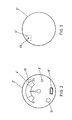
Figure 1 . It shows a schematic view of a practical implementation of a fire protection facility formed by a pressure group, two equipped fire hydrants and a series of fire extinguishers that are communicated via radio with a control station. -
Figure 2 . It shows a front view of a pressure gauge relating to a fire extinguisher provided with a LED light, communication via radio, a battery and Bluetooth transmission and which is associated to the safety pin of the same. -
Figure 3 . It shows a rear view of the pressure gauge of the previous figure and it can be seen how the same is provided with a small hole in which the safety pin or an element linked to the same fits, to be able to control a possible release of the safety pin. - In view of the aforementioned figures and according to the adopted numbering it can be seen how the control system of fire protection facilities is applicable in all types of fire protection facilities having, at least, one pressure group, and/or, at least, one equipped fire hydrant and/or, at least, one fire extinguisher, such that on the basis of a system in which the pressure gauges of the different components of the facility are equipped with a LED light and means of communication via radio or equivalent, it is about providing with a battery and Bluetooth transmission all the pressure gauges, while, in addition, the pressure gauges relating to the fire extinguishers are associated with the safety pin of the actuating lever of the same.
- In addition, the control system of the fire protection facility has a
control centre 11 with, at least, onemonitoring station 12 of the signal sent by the different components of the facility, and said incidents are communicated, via e-mail, telephone or SMS, to acomputer 13 receiving information from the different components of the facility and this is communicated to the mobile or fixed telephone network, having, at least, onestorage database 14 of the plane of the facility to be controlled with the location of the different components of the same. - The warning receiving centre equipped with a
computer 18 receiving information about the status of the facility will be associated with a keyboard and ascreen 17 and may be located in the place of the facility or in a different place as it may be in the maintenance company. - Thus, according to
figure 1 of the drawings and by way of example, the pressure group 1 is equipped with apressure gauge 2 provided with aLED light 3, means of communication viaradio 4, abattery 5 and Bluetoothtransmission 6. - In this way, If the pressure in the group falls below a certain parameter the
warning LED light 5 will be switched on and the means of communication viaradio 4 will send a communication to thestation 12 of acontrol centre 11, in real time, notifying the incidence produced to be able to act accordingly. - Likewise, the equipped fire hydrants 7 are provided with a pressure gauge 2' also provided with a LED light 3', means of communication via radio 4', a battery 5' and Bluetooth transmission 6', such that if the pressure of the same is below certain parameter the warning LED light 3' will be switched on and the means of communication via radio 4' will send a communication to the
station 12 of acontrol centre 11, in real time, notifying the incidence produced to be able to act accordingly. In the same way, thedifferent fire extinguishers 8 of the facility are equipped with apressure gauge 2" provided with aLED light 3", means of communication viaradio 4", abattery 5" and Bluetoothtransmission 6", such that if the pressure of any of them is not the optimal, thewarning LED light 3" will be switched on and the means of communication viaradio 4" will send a communication to thestation 12 of acontrol centre 11, in real time, notifying the incidence produced to be able to act accordingly. - In this way, the fire protection facility is perfectly monitored, so that any incident that occurs in the same is notified in real time to a
station 12 of acontrol centre 11 that will communicate it to awarning receiving centre 18 that may be located in the maintenance company, in the facilities of the owner of the fire protection facility or both, with a 24-hour monitoring. - Thus, at the moment of the occurrence of a failure in the facility and after it is communicated to the
station 12 of thecontrol centre 11 through the customized software, the component that sends the communication caused by the incidence produced is detected on the plane of the facility, properly stored in thedatabase 14, in which all the components of the same are determined, so that its location is known. - Simultaneously with this, the red LED light is turned on, visual signal of the failure of the corresponding component.
- In addition, with the object of having complete control of the facility, and in particular of the fire extinguishers or the like, the safety pin of the actuating
lever 9 that anchors it with respect to thefixed handle 10, is associated with thepressure gauge 2" to control a possible release of the same. - Thus, in a first practical implementation, the
safety pin 15 of the fire extinguisher can fit in asmall hole 19 of thepressure gauge 2" being associated with the means ofcommunication 4", such that when thesafety pin 15 is released it detects this and sends a communication to thestation 12 of thecontrol centre 11 of the incidence produced and having perfect knowledge of the fire extinguisher 8 in which the incidence has occurred. - That is, when the
safety pin 15 is not in contact with the means of communication, a signal via radio will be emitted to thestation 12 of thecontrol centre 11 to give notice of the incidence produced. - In a second practical implementation of the invention the
safety pin 15 can be linked to a metallic or non-metallic element, such as a strand or wire that will fit in thesmall hole 19 of thepressure gauge 2" associated with the means ofcommunication 4" to detect manipulation of the same. - This is intended to prevent the release of the
safety pin 15 from the actuatinglever 9 and the accidental discharge of thefire extinguisher 8 losing efficiency or being rendered unusable. - On the other hand, by providing the pressure gauges of all the components of the facility (pressure group, equipped fire hydrant and fire extinguishers) with Bluetooth
transmission - In addition, the Bluetooth system can be activated from the control centre so that the battery is not consumed except when performing the maintenance.
- Depending on the size that the fire protection facility may have, the same may include one or
more radio repeaters 16 for the appropriate communication of the information. - The improvements made in the control system of fire protection facilities provide the following advantages, in addition to those already mentioned in document
EP 1238228 : - √ obtainment of the status of the pressure gauges of all the components of the facility, by means of a tablet, mobile telephone, PDA or the like;
- √ control of the possible theft or loss of the safety pin of the actuating lever of the fire extinguishers, and;
- √ activation of the Bluetooth system from the control centre when it is going to be used, preventing the consumption of the battery included in the pressure gauges.
- In short, the object is to be able to remedy any failure of the components of the fire protection facility immediately when they occur, so that all the components are always available.
Claims (3)
- Control system of fire protection facilities, being of the type of fire protection facilities installed in all types of buildings and warehouses fitted with, at least, one pressure group and/or, at least, one equipped fire hydrant and/or, at least, one fire extinguisher with the corresponding function means, and which facilities comprise:√ at least, one pressure group (1) equipped with a pressure gauge (2) provided with a LED light (3) and means of communication via radio (4) or wiring;√ at least, one equipped fire hydrant (7) equipped with a pressure gauge (2') provided with a LED light (3') and means of communication via radio (4') or wiring;√ at least, one fire extinguisher (8) equipped with a pressure gauge (2") provided with a LED light (3") and means of communication via radio (4") or wiring;√ a control centre (11) with, at least, one monitoring station (12) responsible for receiving the warning signal from the various components of the facility;√ a warning receiving centre (18) equipped with, at least, one computer (13) receiving information about the components of the facility from the monitoring station (12) of the control centre (11) via SMS, e-mail or telephone and is connected to the mobile or land telephone network, and the warning receiving centre (18) may be in the facilities of the client or in the maintenance company, and;√ a storage database (14) of the plane of the facility to be controlled with the location of the different components of the same,characterized in that:➢ the pressure gauge (2), (2') and (2") of all the components of the facility relating to pressure group (1), equipped fire hydrant (7) and fire extinguisher (8), are provided with a power supply battery (5), (5') and (5") and include Bluetooth transmission (6), (6') and (6"), respectively, and;➢ the safety pin (15) of the fire extinguishers or similar (8) is associated with the corresponding pressure gauge (2") of the same.
- Control system of fire protection facilities, according to claim 1, characterized in that the safety pin (15), associated with the pressure gauge (2") is inserted, by one of its ends, in a small hole (19) of the pressure gauge itself in contact with the means of communication (4").
- Control system of fire protection facilities, according to claim 1, characterized in that the safety pin (15), associated with the pressure gauge (2"), is connected to the same by means of an element, inserted in a small hole (19) of the pressure gauge itself (2") in contact with the means of communication (4").
Priority Applications (6)
| Application Number | Priority Date | Filing Date | Title |
|---|---|---|---|
| ES13382078.7T ES2682720T3 (en) | 2013-03-08 | 2013-03-08 | Fire protection facilities control system |
| PL13382078T PL2774656T3 (en) | 2013-03-08 | 2013-03-08 | Control system of fire protection facilities |
| PT133820787T PT2774656T (en) | 2013-03-08 | 2013-03-08 | Control system of fire protection facilities |
| EP13382078.7A EP2774656B1 (en) | 2013-03-08 | 2013-03-08 | Control system of fire protection facilities |
| NO13382078A NO2774656T3 (en) | 2013-03-08 | 2013-03-08 | |
| US13/941,672 US9155928B2 (en) | 2012-07-19 | 2013-07-15 | Control system for fire prevention facilities |
Applications Claiming Priority (1)
| Application Number | Priority Date | Filing Date | Title |
|---|---|---|---|
| EP13382078.7A EP2774656B1 (en) | 2013-03-08 | 2013-03-08 | Control system of fire protection facilities |
Publications (2)
| Publication Number | Publication Date |
|---|---|
| EP2774656A1 true EP2774656A1 (en) | 2014-09-10 |
| EP2774656B1 EP2774656B1 (en) | 2018-01-03 |
Family
ID=47998366
Family Applications (1)
| Application Number | Title | Priority Date | Filing Date |
|---|---|---|---|
| EP13382078.7A Active EP2774656B1 (en) | 2012-07-19 | 2013-03-08 | Control system of fire protection facilities |
Country Status (5)
| Country | Link |
|---|---|
| EP (1) | EP2774656B1 (en) |
| ES (1) | ES2682720T3 (en) |
| NO (1) | NO2774656T3 (en) |
| PL (1) | PL2774656T3 (en) |
| PT (1) | PT2774656T (en) |
Cited By (2)
| Publication number | Priority date | Publication date | Assignee | Title |
|---|---|---|---|---|
| CN111429094A (en) * | 2020-03-20 | 2020-07-17 | 北斗联合(浙江)安全科技有限公司 | Fire safety code big data management system |
| CN114887270A (en) * | 2022-05-22 | 2022-08-12 | 安徽世纪凯旋消防科技有限公司 | Warning device and monitoring method for gas fire extinguishing system not entering working state |
Citations (5)
| Publication number | Priority date | Publication date | Assignee | Title |
|---|---|---|---|---|
| US5982274A (en) * | 1995-05-16 | 1999-11-09 | Master Control Systems, Inc. | Paperless pressure and alarm recorder |
| EP1238228A1 (en) | 1999-12-16 | 2002-09-11 | 3M Innovative Properties Company | Light tube |
| US20060283608A1 (en) * | 2005-06-16 | 2006-12-21 | Hauck Curt A | Fire extinguisher activating a remote alarm |
| WO2010035150A1 (en) * | 2008-09-29 | 2010-04-01 | Melli Automazione S.R.L. | A monitoring device for a fire-fighting equipment |
| CN201893012U (en) * | 2010-08-23 | 2011-07-06 | 周晔 | Pressure detection system of fire extinguisher based on wireless sensing network |
-
2013
- 2013-03-08 ES ES13382078.7T patent/ES2682720T3/en active Active
- 2013-03-08 PL PL13382078T patent/PL2774656T3/en unknown
- 2013-03-08 EP EP13382078.7A patent/EP2774656B1/en active Active
- 2013-03-08 PT PT133820787T patent/PT2774656T/en unknown
- 2013-03-08 NO NO13382078A patent/NO2774656T3/no unknown
Patent Citations (5)
| Publication number | Priority date | Publication date | Assignee | Title |
|---|---|---|---|---|
| US5982274A (en) * | 1995-05-16 | 1999-11-09 | Master Control Systems, Inc. | Paperless pressure and alarm recorder |
| EP1238228A1 (en) | 1999-12-16 | 2002-09-11 | 3M Innovative Properties Company | Light tube |
| US20060283608A1 (en) * | 2005-06-16 | 2006-12-21 | Hauck Curt A | Fire extinguisher activating a remote alarm |
| WO2010035150A1 (en) * | 2008-09-29 | 2010-04-01 | Melli Automazione S.R.L. | A monitoring device for a fire-fighting equipment |
| CN201893012U (en) * | 2010-08-23 | 2011-07-06 | 周晔 | Pressure detection system of fire extinguisher based on wireless sensing network |
Cited By (4)
| Publication number | Priority date | Publication date | Assignee | Title |
|---|---|---|---|---|
| CN111429094A (en) * | 2020-03-20 | 2020-07-17 | 北斗联合(浙江)安全科技有限公司 | Fire safety code big data management system |
| CN111429094B (en) * | 2020-03-20 | 2023-06-27 | 北斗联合(浙江)安全科技有限公司 | Fire safety code big data management system |
| CN114887270A (en) * | 2022-05-22 | 2022-08-12 | 安徽世纪凯旋消防科技有限公司 | Warning device and monitoring method for gas fire extinguishing system not entering working state |
| CN114887270B (en) * | 2022-05-22 | 2023-11-21 | 安徽世纪凯旋消防科技有限公司 | Warning device and monitoring method for non-entering working state of gas fire extinguishing system |
Also Published As
| Publication number | Publication date |
|---|---|
| PL2774656T3 (en) | 2018-07-31 |
| NO2774656T3 (en) | 2018-06-02 |
| PT2774656T (en) | 2018-03-19 |
| ES2682720T3 (en) | 2018-09-21 |
| EP2774656B1 (en) | 2018-01-03 |
Similar Documents
| Publication | Publication Date | Title |
|---|---|---|
| US9155928B2 (en) | Control system for fire prevention facilities | |
| CA2896639C (en) | Equipment for the remote control of fire extinguishers and/or hydrants | |
| KR101811393B1 (en) | Remote Control System for Automatic Fire Alarm Equiment | |
| EP2687269B1 (en) | Remote monitoring device of fire-fighting equipment | |
| KR20160010896A (en) | Smart fire-fighting management system for cultural assets and method thereof | |
| CN112156413B (en) | Fire extinguisher management system and method | |
| EP2774656B1 (en) | Control system of fire protection facilities | |
| KR101673768B1 (en) | Immersion detection alarms and alarm systems | |
| KR20070085192A (en) | Remote control system of a carbon dioxide(halon replacement) | |
| CN202306754U (en) | Intelligent wireless fire control alarming system | |
| KR20040087995A (en) | Network Fire Prevention System and Service Method | |
| KR200423964Y1 (en) | Monitoring system of fire engine with server | |
| CN208589125U (en) | Fire extinguisher remote monitoring system | |
| KR101828028B1 (en) | Remote control system the fire extinguisher using a noncombustible gas nitrogen or IG-541 | |
| CN106297136A (en) | Intelligent fire-pretection system | |
| KR101206731B1 (en) | Method and System for Detecting Error State of Autometic Fire-Extinguishing System | |
| KR102567847B1 (en) | Fire prevention system equipped with emergency sound device fire extinguisher | |
| KR200466538Y1 (en) | solenoid step by step control system for ejection of dry chemical powder | |
| ITTO20120498A1 (en) | ALARM SYSTEM FOR AN AREA TO MONITOR, IN PARTICULAR A COMMERCIAL OR INDUSTRIAL AREA, AS A CONSTRUCTION SITE. | |
| KR20110109134A (en) | Fire prevention management system using power line communication | |
| CN216739855U (en) | Measurable fire hydrant | |
| US11350262B1 (en) | Self-contained disaster condition monitoring system | |
| TWM556906U (en) | Fire alarm receiver system | |
| JP4964703B2 (en) | Earthquake information transmission method and system | |
| KR200429451Y1 (en) | P-type compound fire receiver |
Legal Events
| Date | Code | Title | Description |
|---|---|---|---|
| PUAI | Public reference made under article 153(3) epc to a published international application that has entered the european phase |
Free format text: ORIGINAL CODE: 0009012 |
|
| 17P | Request for examination filed |
Effective date: 20140403 |
|
| AK | Designated contracting states |
Kind code of ref document: A1 Designated state(s): AL AT BE BG CH CY CZ DE DK EE ES FI FR GB GR HR HU IE IS IT LI LT LU LV MC MK MT NL NO PL PT RO RS SE SI SK SM TR |
|
| AX | Request for extension of the european patent |
Extension state: BA ME |
|
| 17Q | First examination report despatched |
Effective date: 20160907 |
|
| GRAP | Despatch of communication of intention to grant a patent |
Free format text: ORIGINAL CODE: EPIDOSNIGR1 |
|
| RIC1 | Information provided on ipc code assigned before grant |
Ipc: A62C 13/76 20060101ALI20170628BHEP Ipc: A62C 37/50 20060101AFI20170628BHEP Ipc: G05B 23/02 20060101ALN20170628BHEP |
|
| INTG | Intention to grant announced |
Effective date: 20170725 |
|
| GRAS | Grant fee paid |
Free format text: ORIGINAL CODE: EPIDOSNIGR3 |
|
| GRAA | (expected) grant |
Free format text: ORIGINAL CODE: 0009210 |
|
| AK | Designated contracting states |
Kind code of ref document: B1 Designated state(s): AL AT BE BG CH CY CZ DE DK EE ES FI FR GB GR HR HU IE IS IT LI LT LU LV MC MK MT NL NO PL PT RO RS SE SI SK SM TR |
|
| REG | Reference to a national code |
Ref country code: GB Ref legal event code: FG4D |
|
| REG | Reference to a national code |
Ref country code: CH Ref legal event code: EP Ref country code: AT Ref legal event code: REF Ref document number: 959690 Country of ref document: AT Kind code of ref document: T Effective date: 20180115 |
|
| REG | Reference to a national code |
Ref country code: IE Ref legal event code: FG4D |
|
| REG | Reference to a national code |
Ref country code: DE Ref legal event code: R096 Ref document number: 602013031589 Country of ref document: DE |
|
| REG | Reference to a national code |
Ref country code: PT Ref legal event code: SC4A Ref document number: 2774656 Country of ref document: PT Date of ref document: 20180319 Kind code of ref document: T Free format text: AVAILABILITY OF NATIONAL TRANSLATION Effective date: 20180308 |
|
| REG | Reference to a national code |
Ref country code: FR Ref legal event code: PLFP Year of fee payment: 6 |
|
| REG | Reference to a national code |
Ref country code: CH Ref legal event code: NV Representative=s name: WALDER WYSS AG, CH |
|
| REG | Reference to a national code |
Ref country code: NL Ref legal event code: FP |
|
| REG | Reference to a national code |
Ref country code: LT Ref legal event code: MG4D |
|
| REG | Reference to a national code |
Ref country code: NO Ref legal event code: T2 Effective date: 20180103 |
|
| REG | Reference to a national code |
Ref country code: AT Ref legal event code: MK05 Ref document number: 959690 Country of ref document: AT Kind code of ref document: T Effective date: 20180103 |
|
| PG25 | Lapsed in a contracting state [announced via postgrant information from national office to epo] |
Ref country code: CY Free format text: LAPSE BECAUSE OF FAILURE TO SUBMIT A TRANSLATION OF THE DESCRIPTION OR TO PAY THE FEE WITHIN THE PRESCRIBED TIME-LIMIT Effective date: 20180103 Ref country code: HR Free format text: LAPSE BECAUSE OF FAILURE TO SUBMIT A TRANSLATION OF THE DESCRIPTION OR TO PAY THE FEE WITHIN THE PRESCRIBED TIME-LIMIT Effective date: 20180103 Ref country code: LT Free format text: LAPSE BECAUSE OF FAILURE TO SUBMIT A TRANSLATION OF THE DESCRIPTION OR TO PAY THE FEE WITHIN THE PRESCRIBED TIME-LIMIT Effective date: 20180103 Ref country code: FI Free format text: LAPSE BECAUSE OF FAILURE TO SUBMIT A TRANSLATION OF THE DESCRIPTION OR TO PAY THE FEE WITHIN THE PRESCRIBED TIME-LIMIT Effective date: 20180103 |
|
| PG25 | Lapsed in a contracting state [announced via postgrant information from national office to epo] |
Ref country code: RS Free format text: LAPSE BECAUSE OF FAILURE TO SUBMIT A TRANSLATION OF THE DESCRIPTION OR TO PAY THE FEE WITHIN THE PRESCRIBED TIME-LIMIT Effective date: 20180103 Ref country code: SE Free format text: LAPSE BECAUSE OF FAILURE TO SUBMIT A TRANSLATION OF THE DESCRIPTION OR TO PAY THE FEE WITHIN THE PRESCRIBED TIME-LIMIT Effective date: 20180103 Ref country code: LV Free format text: LAPSE BECAUSE OF FAILURE TO SUBMIT A TRANSLATION OF THE DESCRIPTION OR TO PAY THE FEE WITHIN THE PRESCRIBED TIME-LIMIT Effective date: 20180103 Ref country code: AT Free format text: LAPSE BECAUSE OF FAILURE TO SUBMIT A TRANSLATION OF THE DESCRIPTION OR TO PAY THE FEE WITHIN THE PRESCRIBED TIME-LIMIT Effective date: 20180103 Ref country code: IS Free format text: LAPSE BECAUSE OF FAILURE TO SUBMIT A TRANSLATION OF THE DESCRIPTION OR TO PAY THE FEE WITHIN THE PRESCRIBED TIME-LIMIT Effective date: 20180503 Ref country code: BG Free format text: LAPSE BECAUSE OF FAILURE TO SUBMIT A TRANSLATION OF THE DESCRIPTION OR TO PAY THE FEE WITHIN THE PRESCRIBED TIME-LIMIT Effective date: 20180403 |
|
| REG | Reference to a national code |
Ref country code: ES Ref legal event code: NE2A Effective date: 20180913 |
|
| REG | Reference to a national code |
Ref country code: ES Ref legal event code: FG2A Ref document number: 2682720 Country of ref document: ES Kind code of ref document: T3 Effective date: 20180921 |
|
| REG | Reference to a national code |
Ref country code: DE Ref legal event code: R097 Ref document number: 602013031589 Country of ref document: DE |
|
| PG25 | Lapsed in a contracting state [announced via postgrant information from national office to epo] |
Ref country code: AL Free format text: LAPSE BECAUSE OF FAILURE TO SUBMIT A TRANSLATION OF THE DESCRIPTION OR TO PAY THE FEE WITHIN THE PRESCRIBED TIME-LIMIT Effective date: 20180103 Ref country code: RO Free format text: LAPSE BECAUSE OF FAILURE TO SUBMIT A TRANSLATION OF THE DESCRIPTION OR TO PAY THE FEE WITHIN THE PRESCRIBED TIME-LIMIT Effective date: 20180103 Ref country code: EE Free format text: LAPSE BECAUSE OF FAILURE TO SUBMIT A TRANSLATION OF THE DESCRIPTION OR TO PAY THE FEE WITHIN THE PRESCRIBED TIME-LIMIT Effective date: 20180103 |
|
| PLBE | No opposition filed within time limit |
Free format text: ORIGINAL CODE: 0009261 |
|
| STAA | Information on the status of an ep patent application or granted ep patent |
Free format text: STATUS: NO OPPOSITION FILED WITHIN TIME LIMIT |
|
| PG25 | Lapsed in a contracting state [announced via postgrant information from national office to epo] |
Ref country code: SK Free format text: LAPSE BECAUSE OF FAILURE TO SUBMIT A TRANSLATION OF THE DESCRIPTION OR TO PAY THE FEE WITHIN THE PRESCRIBED TIME-LIMIT Effective date: 20180103 Ref country code: CZ Free format text: LAPSE BECAUSE OF FAILURE TO SUBMIT A TRANSLATION OF THE DESCRIPTION OR TO PAY THE FEE WITHIN THE PRESCRIBED TIME-LIMIT Effective date: 20180103 Ref country code: SM Free format text: LAPSE BECAUSE OF FAILURE TO SUBMIT A TRANSLATION OF THE DESCRIPTION OR TO PAY THE FEE WITHIN THE PRESCRIBED TIME-LIMIT Effective date: 20180103 Ref country code: DK Free format text: LAPSE BECAUSE OF FAILURE TO SUBMIT A TRANSLATION OF THE DESCRIPTION OR TO PAY THE FEE WITHIN THE PRESCRIBED TIME-LIMIT Effective date: 20180103 Ref country code: MC Free format text: LAPSE BECAUSE OF FAILURE TO SUBMIT A TRANSLATION OF THE DESCRIPTION OR TO PAY THE FEE WITHIN THE PRESCRIBED TIME-LIMIT Effective date: 20180103 |
|
| REG | Reference to a national code |
Ref country code: BE Ref legal event code: MM Effective date: 20180331 |
|
| 26N | No opposition filed |
Effective date: 20181005 |
|
| REG | Reference to a national code |
Ref country code: IE Ref legal event code: MM4A |
|
| PG25 | Lapsed in a contracting state [announced via postgrant information from national office to epo] |
Ref country code: LU Free format text: LAPSE BECAUSE OF NON-PAYMENT OF DUE FEES Effective date: 20180308 |
|
| PG25 | Lapsed in a contracting state [announced via postgrant information from national office to epo] |
Ref country code: IE Free format text: LAPSE BECAUSE OF NON-PAYMENT OF DUE FEES Effective date: 20180308 |
|
| PG25 | Lapsed in a contracting state [announced via postgrant information from national office to epo] |
Ref country code: BE Free format text: LAPSE BECAUSE OF NON-PAYMENT OF DUE FEES Effective date: 20180331 Ref country code: SI Free format text: LAPSE BECAUSE OF FAILURE TO SUBMIT A TRANSLATION OF THE DESCRIPTION OR TO PAY THE FEE WITHIN THE PRESCRIBED TIME-LIMIT Effective date: 20180103 |
|
| PG25 | Lapsed in a contracting state [announced via postgrant information from national office to epo] |
Ref country code: MT Free format text: LAPSE BECAUSE OF NON-PAYMENT OF DUE FEES Effective date: 20180308 |
|
| PG25 | Lapsed in a contracting state [announced via postgrant information from national office to epo] |
Ref country code: TR Free format text: LAPSE BECAUSE OF FAILURE TO SUBMIT A TRANSLATION OF THE DESCRIPTION OR TO PAY THE FEE WITHIN THE PRESCRIBED TIME-LIMIT Effective date: 20180103 |
|
| PG25 | Lapsed in a contracting state [announced via postgrant information from national office to epo] |
Ref country code: HU Free format text: LAPSE BECAUSE OF FAILURE TO SUBMIT A TRANSLATION OF THE DESCRIPTION OR TO PAY THE FEE WITHIN THE PRESCRIBED TIME-LIMIT; INVALID AB INITIO Effective date: 20130308 |
|
| PG25 | Lapsed in a contracting state [announced via postgrant information from national office to epo] |
Ref country code: GR Free format text: LAPSE BECAUSE OF FAILURE TO SUBMIT A TRANSLATION OF THE DESCRIPTION OR TO PAY THE FEE WITHIN THE PRESCRIBED TIME-LIMIT Effective date: 20180103 Ref country code: MK Free format text: LAPSE BECAUSE OF NON-PAYMENT OF DUE FEES Effective date: 20180103 |
|
| PGFP | Annual fee paid to national office [announced via postgrant information from national office to epo] |
Ref country code: NO Payment date: 20230327 Year of fee payment: 11 Ref country code: FR Payment date: 20230327 Year of fee payment: 11 |
|
| PGFP | Annual fee paid to national office [announced via postgrant information from national office to epo] |
Ref country code: PT Payment date: 20230303 Year of fee payment: 11 Ref country code: PL Payment date: 20230223 Year of fee payment: 11 Ref country code: IT Payment date: 20230323 Year of fee payment: 11 |
|
| PGFP | Annual fee paid to national office [announced via postgrant information from national office to epo] |
Ref country code: NL Payment date: 20230317 Year of fee payment: 11 |
|
| PGFP | Annual fee paid to national office [announced via postgrant information from national office to epo] |
Ref country code: ES Payment date: 20230401 Year of fee payment: 11 Ref country code: DE Payment date: 20230426 Year of fee payment: 11 Ref country code: CH Payment date: 20230401 Year of fee payment: 11 |
|
| PGFP | Annual fee paid to national office [announced via postgrant information from national office to epo] |
Ref country code: GB Payment date: 20230426 Year of fee payment: 11 |
|
| REG | Reference to a national code |
Ref country code: DE Ref legal event code: R082 Ref document number: 602013031589 Country of ref document: DE Representative=s name: SEYER & NOBBE PATENTANWAELTE PARTNERSCHAFTSGES, DE |
|
| PGFP | Annual fee paid to national office [announced via postgrant information from national office to epo] |
Ref country code: NL Payment date: 20240305 Year of fee payment: 12 |