EP2777616A1 - Prosthesis for atraumatically grasping intralumenal tissue - Google Patents
Prosthesis for atraumatically grasping intralumenal tissue Download PDFInfo
- Publication number
- EP2777616A1 EP2777616A1 EP14159271.7A EP14159271A EP2777616A1 EP 2777616 A1 EP2777616 A1 EP 2777616A1 EP 14159271 A EP14159271 A EP 14159271A EP 2777616 A1 EP2777616 A1 EP 2777616A1
- Authority
- EP
- European Patent Office
- Prior art keywords
- frame
- anchors
- proximal
- distal
- prosthesis
- Prior art date
- Legal status (The legal status is an assumption and is not a legal conclusion. Google has not performed a legal analysis and makes no representation as to the accuracy of the status listed.)
- Granted
Links
Images


Classifications
-
- A—HUMAN NECESSITIES
- A61—MEDICAL OR VETERINARY SCIENCE; HYGIENE
- A61F—FILTERS IMPLANTABLE INTO BLOOD VESSELS; PROSTHESES; DEVICES PROVIDING PATENCY TO, OR PREVENTING COLLAPSING OF, TUBULAR STRUCTURES OF THE BODY, e.g. STENTS; ORTHOPAEDIC, NURSING OR CONTRACEPTIVE DEVICES; FOMENTATION; TREATMENT OR PROTECTION OF EYES OR EARS; BANDAGES, DRESSINGS OR ABSORBENT PADS; FIRST-AID KITS
- A61F2/00—Filters implantable into blood vessels; Prostheses, i.e. artificial substitutes or replacements for parts of the body; Appliances for connecting them with the body; Devices providing patency to, or preventing collapsing of, tubular structures of the body, e.g. stents
- A61F2/02—Prostheses implantable into the body
- A61F2/24—Heart valves ; Vascular valves, e.g. venous valves; Heart implants, e.g. passive devices for improving the function of the native valve or the heart muscle; Transmyocardial revascularisation [TMR] devices; Valves implantable in the body
- A61F2/2412—Heart valves ; Vascular valves, e.g. venous valves; Heart implants, e.g. passive devices for improving the function of the native valve or the heart muscle; Transmyocardial revascularisation [TMR] devices; Valves implantable in the body with soft flexible valve members, e.g. tissue valves shaped like natural valves
- A61F2/2418—Scaffolds therefor, e.g. support stents
-
- A—HUMAN NECESSITIES
- A61—MEDICAL OR VETERINARY SCIENCE; HYGIENE
- A61F—FILTERS IMPLANTABLE INTO BLOOD VESSELS; PROSTHESES; DEVICES PROVIDING PATENCY TO, OR PREVENTING COLLAPSING OF, TUBULAR STRUCTURES OF THE BODY, e.g. STENTS; ORTHOPAEDIC, NURSING OR CONTRACEPTIVE DEVICES; FOMENTATION; TREATMENT OR PROTECTION OF EYES OR EARS; BANDAGES, DRESSINGS OR ABSORBENT PADS; FIRST-AID KITS
- A61F2220/00—Fixations or connections for prostheses classified in groups A61F2/00 - A61F2/26 or A61F2/82 or A61F9/00 or A61F11/00 or subgroups thereof
- A61F2220/0008—Fixation appliances for connecting prostheses to the body
Definitions
- Certain embodiments disclosed herein relate generally to prostheses for implantation within a lumen or body cavity.
- certain embodiments relate to expandable prostheses such as replacement heart valves, such as for the mitral valve, that are configured to atraumatically grasp intralumenal tissue.
- Human heart valves which include the aortic, pulmonary, mitral and tricuspid valves, function essentially as one-way valves operating in synchronization with the pumping heart.
- the valves allow blood to flow downstream, but block blood from flowing upstream.
- Diseased heart valves exhibit impairments such as narrowing of the valve or regurgitation, which inhibit the valves' ability to control blood flow.
- Such impairments reduce the heart's blood-pumping efficiency and can be a debilitating and life threatening condition.
- valve insufficiency can lead to conditions such as heart hypertrophy and dilation of the ventricle.
- extensive efforts have been made to develop methods and apparatuses to repair or replace impaired heart valves.
- Prostheses exist to correct problems associated with impaired heart valves.
- mechanical and tissue-based heart valve prostheses can be used to replace impaired native heart valves.
- substantial effort has been dedicated to developing replacement heart valves, particularly tissue-based replacement heart valves that can be delivered with less trauma to the patient than through open heart surgery.
- Replacement valves are being designed to be delivered through minimally invasive procedures and even percutaneous procedures.
- Such replacement valves often include a tissue-based valve body that is connected to an expandable frame that is then delivered to the native valve's annulus.
- prostheses including but not limited to replacement heart valves that can be compacted for delivery and then controllably expanded for controlled placement has proven to be particularly challenging.
- An additional challenge relates to the ability of such prostheses to be secured relative to intralumenal tissue, e.g., tissue within any body lumen or cavity, in an atraumatic manner.
- Further challenges arise when trying to controllably deliver and secure such prostheses in a location such as at a native mitral valve.
- These replacement valves are often intended to at least partially block blood flow.
- a problem occurs when blood flows around the valve on the outside of the prosthesis. For example, in the context of replacement heart valves, paravalvular leakage has proven particularly challenging.
- Embodiments of the present disclosure are directed to a prosthesis, such as but not limited to a replacement heart valve. Further embodiments are directed to methods of delivering a prosthesis into a body cavity and/or securing a prosthesis to intralumenal tissue. In some embodiments, a replacement heart valve and methods for delivering a replacement heart valve to a native heart valve, such as a mitral valve, are provided.
- a prosthesis can comprise an expandable frame, and a plurality of anchors, for example a plurality of proximal anchors and a plurality of distal anchors.
- the expandable frame may comprise a proximal end and a distal end and having a longitudinal axis extending between the proximal end and the distal end.
- the anchors can extend outwardly from the frame.
- the frame can be configured to radially expand and contract for deployment within the body cavity.
- the frame comprises a plurality of foreshortening cells causing a longitudinal length of the frame to decrease as the frame moves from a collapsed size to an expanded size.
- proximal anchors and distal anchors may be separated by a foreshortening portion of the frame.
- some of the plurality of anchors may be connected to a non-foreshortening portion of the frame, and some of the plurality of anchors are connected to a foreshortening portion of the frame.
- the frame when the frame is in an expanded configuration, can have a larger cross-sectional dimension in a middle portion of the frame and a smaller cross-sectional dimension in a proximal portion and a distal portion of the frame, wherein the middle portion is between the proximal and distal portions.
- the frame may have a cylindrical or substantially cylindrical shape when in an expanded configuration, wherein the proximal end and the distal end of the frame have the same or substantially the same cross-sectional dimension.
- At least some of the anchors, or alternatively all of the anchors comprise a loop that forms an atraumatic end of a corresponding anchor.
- proximal anchors and/or distal anchors may comprise looped ends.
- the anchors having looped ends may connect to the frame at spaced apart base locations.
- the spaced apart locations may be at opposite corners of the same cell of a frame.
- at least some anchors which may or may not have looped ends may connect to the frame with a single strut. Adjacent ends of anchors may be circumferentially spaced apart by one or more cells of the frame.
- a width of each of the plurality of anchors having looped ends as defined circumferentially around the longitudinal axis over the entire length of the anchor from the base to the looped end is less than the width of one cell of the frame.
- the looped ends of each anchor may be circumferentially aligned with the base where the anchor connects to the frame so that the looped end and the base are both located within a common plane that is parallel to and intersects the longitudinal axis.
- the base of each of the plurality of proximal and/or distal anchors is at a location where corners of two adjacent cells of the frame meet. In some embodiments, the base of each of the plurality of distal anchors is at a distalmost corner of a cell. In some embodiments, the base of each of the plurality of proximal anchors is at a proximalmost corner of a cell. In some embodiments, the ends of the plurality of distal anchors are not circumferentially aligned with the ends of the plurality proximal anchors when the frame is in an expanded configuration.
- a prosthesis according to certain embodiments can comprise a plurality of proximal anchors connected to the frame so that when the frame is in an expanded configuration an end of each proximal anchor is positioned radially outward from the frame and extends generally distally.
- a plurality of distal anchors may be connected to the frame so that when the frame is in an expanded configuration an end of each distal anchor is positioned radially outward from the frame and extends generally proximally.
- the ends of the distal anchors may be axially spaced from the ends of the proximal anchors when the frame is in an expanded configuration.
- the frame is configured such that radial expansion of the frame causes the ends of the plurality of proximal anchors and the ends of the plurality of distal anchors to draw closer together.
- a plurality of proximal anchors may extend from the frame and be expandable from a collapsed configuration to an expanded configuration, wherein in the expanded configuration, each proximal anchor extends proximally away from the proximal end of the frame and then turns to extend distally, each proximal anchor extending to an end positioned radially outward from the frame.
- the plurality of proximal anchors may in some embodiments extend from or a near the proximal end of the frame. The ends of the proximal anchors may be distal to the proximal end of the frame or distal to where the proximal anchors connect to the frame when the frame is at least partially expanded and the proximal anchors are in their expanded configuration.
- a plurality of distal anchors may extend from the frame and be expandable from a collapsed configuration to an expanded configuration, wherein in the expanded configuration, each distal anchor extends distally away from the distal end of the frame and then turns to extend proximally, each distal anchor extending to an end positioned radially outward from the frame.
- the plurality of distal anchors may in some embodiments extend from or a near the distal end of the frame. The ends of the distal anchors may be proximal to the distal end of the frame or distal to where the distal anchors connect to the frame when the frame is at least partially expanded and the distal anchors are in their expanded configuration.
- the frame and the plurality of anchors are formed from a single piece of material.
- the frame, the plurality of proximal anchors and the plurality of distal anchors may be formed by laser cutting a metal tube.
- the ends of at least some of the proximal anchors and/or distal anchors are substantially parallel with the longitudinal axis when the frame is at least partially expanded and the proximal and distal anchors are in their expanded configurations.
- the ends of at least some of the proximal anchors and/or distal anchors may be substantially perpendicular with the longitudinal axis when the frame is at least partially expanded and the proximal and distal anchors are in their expanded configurations.
- the ends of at least some of the proximal anchors and/or distal anchors may be inclined with respect to the longitudinal axis when the frame is at least partially expanded and the proximal and distal anchors are in their expanded configurations.
- some of the anchors expand to a first radial distance, and some of the anchors expand to a second radial distance, the first radial distance being greater than the second radial distance.
- at least some of the plurality of proximal anchors may expand to a first radial distance, and at least some of the plurality of distal anchors may expand to a second radial distance, the first radial distance being greater than the second radial distance.
- at least some of the plurality of distal anchors may expand to a first radial distance, and at least some of the plurality of proximal anchors may expand to a second radial distance, the first radial distance being greater than the second radial distance.
- a replacement mitral valve may also be provided that comprises any of the prostheses described herein.
- the frame of a prosthesis may be positionable within a native mitral valve such that proximal anchors atraumatically engage tissue on an atrial side of the native mitral valve annulus, and distal anchors are positionable within the ventricle and have portions that extend generally proximally toward a ventricular side of the native mitral valve annulus.
- the distal anchors may be positionable within the ventricle and extend proximally to ends spaced distally from the native mitral valve annulus.
- the distal anchors may be positionable within the ventricle and extend proximally to ends that engage the native mitral valve annulus.
- the frame may be configured so that it does not apply significant radial force to the native valve annulus to thereby permit the frame to axially reciprocate relative to the native mitral valve annulus.
- at least some of the plurality of anchors are configured to expand to a radial distance from a central longitudinal axis of the frame that is about 150% or more of a radius of the frame when the frame is in an expanded configuration.
- at least some of the plurality of anchors are configured to expand to a radial distance from the central longitudinal axis that is about 180% or more of the radius of the frame when the frame is in an expanded configuration.
- a prosthesis may further comprise an outer skirt surrounding the frame.
- the outer skirt may be connected to or near at least some of the ends of the anchors (e.g., the proximal anchors) and configured to move radially outward with the anchors when the anchors move from a collapsed configuration to an expanded configuration.
- the outer skirt is configured to prevent paravalvular leakage exterior to the frame when the anchors are in an expanded configuration.
- a method of delivering a replacement valve to a native mitral valve can comprise one or more of the following steps.
- the replacement valve comprising a radially expandable frame comprising a proximal end, a distal end, a plurality of distal anchors extending generally proximally from the frame, and a plurality of proximal anchors extending generally distally from the frame. Positioning the replacement valve so that ends of the distal anchors are on a ventricular side of the native leaflets beyond a location where chordae tendineae connect to free ends of the native leaflets.
- a prosthesis can comprise an expandable frame, a plurality of distal anchors and a plurality of proximal anchors.
- the anchors can extend outwardly from the frame.
- the frame can be configured to radially expand and contract for deployment within the body cavity.
- the proximal anchors can extend a significant distance away from the exterior of the frame, such as a length of about one-half or more the diameter of the frame.
- at least some of the anchors comprise a loop that forms an atraumatic end of a corresponding anchor.
- an outer skirt may be positioned annularly around an exterior of the expandable frame and be connected to some of the anchors to create an axial barrier to fluid flow exterior to the frame when deployed within the body cavity.
- a prosthesis can be configured to grasp intralumenal tissue when deployed within a body cavity.
- the prosthesis can comprise an expandable frame, a plurality of proximal anchors connected to the frame, and a plurality of distal anchors connected to the frame.
- the expandable frame can comprise a proximal end and a distal end and a longitudinal axis extending therethrough, the frame configured to collapse radially for delivery and to expand radially upon deployment.
- the plurality of proximal anchors can be expandable to a configuration wherein a portion of each of the proximal anchors extends generally distally and an end of each of the proximal anchors is positioned radially outward from the frame.
- the plurality of distal anchors can be expandable to a configuration wherein a portion of each of the distal anchors extends generally proximally and an end of each of the distal anchors is positioned radially outward from the frame. Expansion of the frame from a first at least partially collapsed size to a second expanded size can cause the ends of the proximal anchors and the ends of the distal anchors to draw closer together. At least some of the plurality of proximal anchors can be configured to expand to a radial distance from a central longitudinal axis of the frame that is about 150% or more of a radius of the frame when the frame is in an expanded configuration.
- the illustrated prosthesis 10 includes a frame 20 that may be self-expanding or balloon expandable.
- the frame 20 can include a proximal end 32, a distal end 34 and proximal 22 and distal 24 anchors.
- the anchors can allow the frame to engage a native valve annulus or other tissue to be implanted at a target location.
- the prosthesis 10 can include one or more of a valve 60, an outer skirt 30, and a valve skirt 70 as will be described in more detail below.
- the valve 60 can be designed to replace a damaged or diseased native heart valve such as a mitral valve; though it will be understood that a replacement valve is not required as part of the prosthesis.
- the prosthesis can be a replacement heart valve similar to that and including features similar to those disclosed in U.S. Provisional Appl. Nos. 61/782,707, filed March 14, 2013 and 61/789,783 filed March 15, 2013 , U.S. Patent No. 8,403,983 and U.S. Publication Nos. 2010/0298931 , 2011/0313515 and 2012/0078353 the entireties of each of which are hereby incorporated by reference and made a part of this specification. This is inclusive of the entire disclosure and is not in any way limited to the disclosure of the replacement heart valve.
- the frame 20 can be made of many different materials, but is preferably made from metal.
- the frame 20 can be made from a shape memory material, such as nitinol.
- a wire frame or a metal tube can be used to make the frame.
- the wire frame of a metal tube can be cut or etched to remove all but the desired metal skeleton.
- a metal tube is laser cut in a repeating pattern to form the frame.
- the flat pattern can be cut from a metal tube and then the tube can be bent and expanded to the shape shown in Figures 1A-B .
- the frame 20 can further be expanded and/or compressed and/or otherwise worked to have the desired shape or shapes, such as for introduction and implantation.
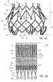
- Figure 1B shows the frame 20 in a partially finished state.
- the frame has been cut and initially expanded, but the anchors 22, 24 have not yet been bent as shown in Figure 1A .
- the frame when in an expanded configuration, such as in a fully expanded configuration, has a cylindrical or slightly cylindrical shape, where a middle portion is substantially similar in shape and size as the proximal 32 and distal 34 ends.
- the frame can be a substantially cylindrical shape with the same or substantially the constant cross-sectional dimension or diameter from the proximal end to the distal end.
- the cylindrical shape of the frame in combination with the anchors described below, can advantageously allow the frame to float within a native valve while the anchors engage a native valve annulus or other body cavity and spacing the inlet and outlet of the frame away from the heart or vessel wall. This can help reduce undesired contact between the prosthesis and the heart or vessel, such as the ventricular wall of the heart.
- the prosthesis 10 and frame 20 may be similar to the replacement heart valves and associated frames disclosed in U.S. Provisional Appl. Nos. 61/782,707, filed March 14, 2013 and 61/789,783 filed March 15, 2013 , U.S. Patent No. 8,403,983 and U.S. Publication Nos. 2010/0298931 and 2011/0313515 the entireties of each of which are hereby incorporated by reference and made a part of this specification. This is inclusive of the entire disclosure and is not in any way limited to the disclosure of the replacement heart valves and associated frames. Further examples of frame and prosthesis configurations that may also be utilized are described with respect to Figures 7A-16B .
- FIG. 1A illustrates the frame in an expanded configuration with a number of longitudinal struts 12 and undulating struts 14, with cells 16, 18 defined by the open spaces between the struts.
- the longitudinal struts may be arranged so that they are parallel or generally or substantially parallel to a longitudinal axis of the frame.
- the longitudinal axis of the frame may be defined as the central axis that extends through the center of the frame between the proximal 32 and distal 34 ends.
- Any number of configurations of struts can be used, such as the rings of undulating struts shown forming chevrons and diamonds, but also ovals, curves, and various other shapes.
- the illustrated embodiment includes two rows of diamond-shaped cells 16 at the top or adjacent the proximal end and then a row of sideways diamond-shaped cells 18 at the bottom or near the distal end.
- These sideways diamond-shapes are made of two longitudinal struts 12 that are offset from one another, or one is higher than the other, and then an undulating strut 14 connects the longitudinal struts 12 at the top and bottom of the cell.
- the sideways diamond-shapes alternate between sides as to which side is higher and which is lower.
- a first sideways diamond-shaped cell 18A has a low left side and a high right side
- a second sideways diamond-shaped 18B had a high left side and a low right side, where the high right side of cell 18A shares the same longitudinal strut 12 as the high left side of cell 18B.
- Some of the struts can include one or more eyelet 46. As illustrated, a plurality of eyelets, here five, are located along one of the longitudinal struts 12 as part of the sideways diamond-shaped cells. One or more eyelets can be positioned in other locations along the frame and/or anchors. The eyelets 46 may be used to attach features such as the valve 60, outer skirt 30, and/or valve skirt 70 to the frame 20.
- the frame 20 as illustrated is foreshortening.
- the foreshortening can be defined by the frame 20 and the positioning of various types of struts along the frame 20.
- the struts 14 become more parallel with respect to the longitudinal axis of the frame, causing cells 16 and 18 to collapse, causing an outer diameter of the frame to decrease and the longitudinal length of the frame to increase.
- the frame moves from a compacted position to an expanded position, the cells 16 and 18 widen sideways and the longitudinal length of the frame can decrease.
- Foreshortening of the frame 20 can be used to engage and secure the prosthesis to intralumenal tissue in a body cavity, for example tissue at or adjacent a native valve, such as a native valve annulus and/or leaflets.
- Opposing anchors 22, 24 can be constructed on the frame 20 so that portions of the anchors, such as tips or ends 26, 28, move closer together as the frame foreshortens. As one example, this can allow the anchors 22, 24 to grasp tissue on opposite sides of the native mitral annulus to thereby secure the prosthesis at the mitral valve.
- the anchors 22, 24 and anchor tips 26, 28 can be located anywhere along the frame 20 just so long as at least one of the anchors is either connected to a foreshortening portion or a foreshortening portion is positioned between the anchors so that a portion of the anchors will be move closer together with expansion of the frame. As shown in Figure 1A , the foreshortening portion extends the entire or substantially the entire length of the frame.
- each of the anchors 22, 24 is positioned or extends generally radially outwardly from the frame 20 so that the anchor tips 26, 28 are generally spaced away or radially outward from the rest of the frame 20.
- the anchor tips may be located radially outward from the middle portion of the frame, with the tips 26 and 28 being axially spaced from one another.
- all or part of the structure connected to the anchor tip and extending radially from the frame, including one or more rings and/or struts can be considered part of the anchor.
- the anchors can include a base located on the anchor on a side opposite the tip. The base can be for example where the anchor begins to extend from or away from the frame 20.
- the distal anchors 24 are shown having looped anchors.
- Each looped anchor has a first base 42 and a second base 44 connected to the frame, wherein the first and second bases are at the distal-most corners of adjacent cells.
- the first and second bases may be located at adjacent corners of the same cell, or at opposite corners of the same cell if for example the cells adjacent the distal end of the frame have the same configuration as the cells shown in Figure 1A at the proximal end of the frame.
- the distal anchors 24 extend generally distally away from the frame and are bent near the base 42 to extend radially outward away from the frame along a first segment 50.
- the anchor is bent to point proximally or generally proximally along a second segment 52 ending in the tip 28.
- the tips 28 of the distal anchors may be curved or arcuate atraumatic tips.
- the ends of the distal anchors can extend proximally and be parallel or substantially parallel with the longitudinal axis of the frame, or they may extend generally proximally but still radially outwardly inclined or at an acute angle relative to the longitudinal axis of the frame.
- the distal anchor 24 then repeats this configuration in reverse towards the second base 44 such that the two sides of the looped anchor are mirror images of one another.
- distal anchors share one strut so that each distal anchor is directly adjacent another distal anchor.
- distal anchors can be spaced apart, for example with at least a cell 18 or two cells 18 located between the distal anchors. It will be understood that the distal anchors can have other configurations such as described in the applications included in the applications incorporated by reference, and for example as shown in Figures 7A-16B , and that the distal anchors may not be symmetrical.
- the proximal anchors 22 are shown having looped anchors of a similar shape and configuration as the distal anchors 24. It can be seen that each proximal anchor extends from or near the proximal end of the frame at bases 54 and 56 located on adjacent proximal-most corners of cells 16. In the embodiment illustrated in Figure 1A , the proximal anchors are longer than the distal anchors, and as such, the proximal anchors may extend further away from the frame. As shown the anchors extend proximally at the bases 54, 56 and are then bent to segment 58 which extends radially outwardly away from the frame in a generally distal direction.
- proximal anchor is bent to point distally or generally distally along a second segment 60 ending in the tip 26.
- the tips 26 of the proximal anchors may be curved or arcuate atraumatic tips.
- the ends of the proximal anchors can extend distally and be parallel or substantially parallel with the longitudinal axis of the frame, or they may extend generally distally but still radially outwardly inclined or at an acute angle relative to the longitudinal axis of the frame.
- Another embodiment, described below with respect to Figure 6 has the ends of the proximal anchors becoming perpendicular to the longitudinal axis of the frame.
- proximal anchors can share the same base where the anchors are bent outward from the frame, or may be considered to extend from the same corner on cell 16.
- proximal anchors can be spaced apart so that there is at least a 1 ⁇ 2 cell or one cell located between the proximal anchors.
- the proximal anchors can have other configurations such as described in the applications incorporated by reference and for example, as shown in Figures 7A-16B , and that the proximal anchors may not be symmetrical.
- a longitudinally extending strut 80 extending proximally, e.g.
- struts 80 may terminate at their proximal ends in an enlarged portion such as a tab 8 that may facilitate holding or retaining the proximal end of the frame, such as in a delivery system as described below.
- proximal anchors in an expanded state such as shown in Figure 1A , at least some of the proximal anchors can extend to a radial distance from an exterior surface of the frame that is 1 ⁇ 2 (or about 1 ⁇ 2) or more of the expanded diameter of the frame. In some embodiments, all of the proximal anchors extend at least to this radial distance. In even further embodiments, all of the proximal and distal anchors extend at least to this radial distance.
- the radial distance of one or more of the ends of the anchors from a central longitudinal axis passing through the middle of the frame may be 150% (or about 150%) or more, 180% (or about 180%) or more, 200% (or about 200%) or more, 220% (or about 220%) or more, or 250% (or about 250%) or more of the radius of the frame when the frame and the anchors are in expanded configurations.
- the radius of the frame is 16 mm and a proximal anchor end is spaced 9 mm from the exterior of the frame, that proximal anchor extends 25 mm from the central longitudinal axis of the frame, and is 156.25% of the radius of the frame.
- the diameter of the frame 20 may be in the range of 20-40 mm (or about 20 to about 40 mm), more preferably 25-35 mm (or about 25 to about 35 mm) when expanded.
- the outermost tip diameter may be greater than the frame diameter as described above and may be in the range of 40-60 mm (or about 40 to about 60 mm), and in some embodiments may be about 50 mm when the frame diameter is about 30 mm.
- the length of the prosthesis, from proximal to distal end, when compressed, is between 20-40 mm (or about 20 to about 40 mm), more preferably 25 to 30 mm (or about 25 to about 30 mm), for example about 29 mm.
- the prosthesis may have a length between 15 to 20 mm (or about 15 to 20 mm), more preferably 17 to 18 mm (or about 17 to about 18 mm).
- the distal anchors 24 can be positioned to be not as far radially outward as the proximal anchors, and the tips 28 may be positioned radially inward of the tips 26. As described further below, such a configuration may be advantageous in positioning and securing the prosthesis in a mitral valve or other body location.
- the ends or tips 26 of the proximal anchors 22 are positioned further radially outward from the frame 20 than the ends of tips 28 distal anchors 24 when the frame and the anchors are in an expanded configuration, e.g., when they are fully expanded.
- the distal anchors and proximal anchors can be positioned at the same radial outward dimension, or the distal anchors may even be positioned further outward than the proximal anchors.
- some of the proximal anchors (or distal anchors) may extend to a first radial distance, and others of the proximal anchors (or distal anchors) may extend to a second radial distance, where the first radial distance is greater than the second radial distance.
- the distal anchors in Figure 1A are shown to be circumferentially staggered with respect to the proximal anchors, meaning that the tips 26 of the proximal anchors are not aligned, and are circumferentially in between the tips 28 of the distal anchors. In other embodiments, the tips 26 and 28 may be circumferentially aligned.
- each of the anchors can extend radially outwardly from the frame at an anchor base and terminate at an anchor tip.
- the anchors can be connected to the frame at one of many different locations including apices, junctions, other parts of struts, etc.
- the anchors can comprise first, second, third, or more spaced apart bending stages along the length of each anchor.
- the anchors can also extend either distally or proximally before and/or after one or more of the bending stages.
- a portion of the anchor may extend with the frame before or after any bending stages.
- the anchors 22, 24 may comprise loops as described above, having a curved or arcuate atraumatic tip to minimize damage to body tissue.
- the prosthesis has nine distal anchors and nine proximal anchors. Any number of proximal and distal anchors may be used. In other embodiments, instead of a 1:1 correspondence between anchors, other ratios, such as a 9:6 or a 9:3 correspondence between the anchors, are possible.
- a third row at the distal end can have a different cell configuration with sideways diamonds as illustrated in Figure 1A , and can for example have eighteen cells 18, with each cell 18 sharing a strut from a cell in the second row.
- the third row can include cells similar in shape to cells 16 in the first and second rows.
- a frame may have one or more rows of diamond-shaped cells, where the number of cells per row is 12 or some other number.
- the anchor tips 26 and 28 as described above advantageously provide atraumatic surfaces that may be used to grasp intralumenal tissue without causing unnecessary or undesired trauma to tissue.
- the proximal anchors tips 26 and distal anchor tips 28 may form flat, substantially flat, curved or other non-sharp surfaces to allow the tips to engage and/or grasp tissue, without necessarily piercing or puncturing through tissue.
- a looped end or looped anchor may assist the frame in not getting caught up on structures at or near the treatment location.
- each loop can be configured so that when the frame is deployed in-situ and the anchors expand away from the frame, the movement of each loop from a delivered position to a deployed position avoids getting caught on the papillary muscles.
- the prosthesis 10 may include a valve 60 as can be seen in schematically in Figure 6 .
- the valve 60 can be a replacement heart valve which includes a plurality of valve leaflets.
- the plurality of valve leaflets can function in a manner similar to the natural mitral valve, or to other valves in the vascular system.
- the plurality of valve leaflets can open in a first position and then engage one another to close the valve in a second position.
- the plurality of valve leaflets can be made to function as a one way valve such that flow in one direction opens the valve and flow in a second direction opposite the first direction closes the valve.
- the replacement heart valve 60 can be constructed so as to open naturally with the beating of the heart. For example, the plurality of valve leaflets can open during diastole and close during systole.
- the leaflets can be coupled to a valve skirt 70.
- Figure 2 shows a seam 62 where the proximal ends of the leaflets can be connected to the valve skirt 70.
- the valve skirt 70 can be used to at least partially control how fluid flows through and/or around the valve 60.
- the valve skirt 70 can surround at least a portion of the valve and be connected to the valve leaflets.
- the valve skirt 70 can form an inner wall connected to and positioned within the frame 20.
- the skirt 70 can connect to the frame at the eyelets 46, such as by stitching.
- the skirt may also be attached directing to the struts, typically also by stitching.
- the valve skirt 70 can also be made to move with the foreshortening portion of the frame 20.
- the valve skirt 70 can extend the length of the frame 20 or it can extend along only part of the length of the frame 20. In some embodiments, the ends of the heart valve 60 can coincide with ends of the valve skirt 70. In addition, one or more of the ends of the frame 20 can coincide with the ends of the valve skirt 70. In the illustrated embodiment of Figure 2 , the proximal end of the valve skirt 70 is positioned proximally from the proximal end of the heart valve 60 as indicated by the seam 62. The valve skirt 70 can not only extend to the distal end of the frame 20 but can also extend to the outside of the frame and is shown attached to and extending to the tip 28 of each distal anchor 24. As shown, the skirt 70 is sewn to each distal anchor.
- valve skirt 70 may extend along the length of the leaflets, but is not connected to them.
- valve skirt 70 is attached to the frame 20 and the leaflets are attached to the valve skirt 70, such as at the seam 62 in Figure 2 .
- the valve skirt 70 can be constructed in multiple different ways.
- the valve skirt 70 can be made a layer of resilient material, such as knit polyester or another stretchable or flexible fabric.
- the valve skirt 70 is made from a material that is more flexible than the valve leaflet material.
- the distal and/or proximal end of the skirt 70 can be straight, curved, or have any other desired configuration.
- the valve skirt 70 is shown with a straight proximal end at the proximal end 32 of the frame.
- the skirt distal end can be patterned to generally correspond to the undulations at one end of the frame 20.
- the valve skirt 70 can be formed of one piece or multiple pieces.
- valve skirt 70 attached to the valve 60 can be one piece and then each distal anchor can be covered by a separate piece of material of the valve skirt 70. It is to be understood that other configurations of the valve skirt 70 can also be employed. For example, the anchors may remain uncovered, or only a portion may be covered.
- valve skirt 70 the end can extend past the frame and can be wrapped around it.
- the valve skirt 70 can extend from the inside of the frame 20 to the outside of the frame.
- the skirt can extend completely around the frame for 1/4, 1/3, 1/2, or more of the length of the distal anchors.
- the skirt 70 can also cover the distal anchors 24 as is shown in Figures 7A and 7B of Provisional Appl. No. 61/782,707 ( Figures 13A and 13B herein) and in Figure 2 herein.
- the skirt can be a one piece skirt, but it will be understood that the skirt can be made of multiple pieces.
- valve skirt 70 and particularly portions that cover the distal anchors 24, can beneficially be used to help prevent leakage of blood flow around the heart valve.
- the skirt can encourage tissue in-growth between the skirt and the natural tissue. This may further help to prevent leakage of blood flow around the heart valve.
- an outer skirt or apron 30 is shown that may also form part of the prosthesis 10.
- Figure 2 shows the outer skirt 30 attached to the frame 20 at the tips 26 of the proximal anchors.
- the outer skirt 30 can have a portion shaped to correspond generally with the shape of an outer portion of the frame 20.
- a first portion 64 of the outer skirt 30 can have a cylindrical or generally cylindrical shape with an inner diameter that substantially corresponds in size to, or may be larger or slightly larger than, an outer diameter of the frame 20.
- the outer skirt 30 can have a second portion 66 with an annular shape that extends away from the first portion 64 to an outer border with a diameter larger than the diameter of the first portion.
- the second portion 66 is shown flaring outward from the first portion 64 and extending generally perpendicularly from the first portion 64.
- the illustrated second portion forms an annular ring comprising a proximal edge and a distal edge, wherein a diameter of the proximal edge is larger than a diameter of the distal edge.
- the outer skirt 30 can attach to the frame, and more preferably attach to the anchors, in one of many different ways.
- the outer skirt 30 can be sewn to the frame and/or valve skirt.
- the outer skirt 30 can also be wrapped around a portion of the frame and then sewn to itself.
- the second portion 66 is attached to the proximal anchors 22.
- a plurality of circumferentially spaced tabs 68 extending radially outward from the proximal edge of the second portion 66 can be used to attach the outer skirt 30 to the proximal anchors.
- the tabs 68 can be wrapped around the tip 26 (e.g., through the loop) of a proximal anchor and connected to the second portion.
- the tabs 68 themselves may also form sleeves that are configured to surround at least a portion of the proximal anchors.
- the proximal anchors 22 can include eyelets that may be used to secure the skirt to the anchor.
- the tab 68 can be attached to the eyelet 46, for example by stitching.
- the outer skirt 30 is only attached to the frame via the proximal anchors, and the first portion 64 remains unattached to any portion of the frame or any anchors.
- the outer skirt is both attached to the proximal anchors and to the middle portion of the frame.
- the second portion 66 attached to the anchors extends inwardly from the proximal anchors 22.
- the first portion 64 then extends distally from the second portion 66 and terminates in a distal edge, which may be free or which may attach to the middle portion of the frame 20 or the skirt 70.
- the first portion 64 may also be attached to portions of the frame and/or the distal anchors.
- the distal edge of the skirt 30 may be spaced radially outward from the frame when the frame is in an expanded configuration.
- the distal edge of the skirt 30 may extend to the distal end of the frame, or it may be spaced proximally therefrom as illustrated in Figure 2 .
- the outer skirt 30 can attach to the frame at a distal end of the skirt, or at some other location and then curve up and out towards the proximal anchors.
- the outer skirt may not have a distinct first portion and second portion.
- the outer skirt may extend along a substantial portion of the frame. Additional examples of outer skirt features that may be incorporated and/or interchanged with the features described herein are found in U.S. Provisional Application No. 61/789,783 filed March 15, 2013 incorporated by reference herein.
- Figures 3 and 4 show additional embodiments of the outer skirt 30', 30".
- the outer skirt 30' extends along a substantial part of the frame and extends between proximal and distal anchors.
- the outer skirt 30' in this embodiment may be one single piece, or may be formed from multiple pieces stitched or otherwise connected together.
- the tabs 68' may form sleeves that are configured to surround at least a portion of the proximal anchors to attach the outer skirt to the proximal anchors. As shown in one embodiment, proximal portions of the proximal anchors remain uncovered by the outer skirt 30'.
- the outer skirt 30' at the proximal anchors can form an annular ring similar to the second portion 66 of Figure 2 and can form a substantially cylindrical portion similar to the first portion 64 of Figure 2 .
- the distal end of the outer skirt 30' can attach and/or cover the distal anchors 24.
- the distal end of the outer skirt 30' extends to the distal anchors 24 but does not cover or connect to them.
- a valve skirt 70 may also be used which may create some overlap of skirts in some embodiments.
- the outer skirt 30" is shown attached to the distal ends of the proximal anchors 22 with tabs 68". The outer skirt 30" then extends proximally to essentially the base of the proximal anchor. From that point, the outer skirt extends distally towards the distal end. Again the outer skirt may or may not attach to the distal anchors. In the illustrated embodiment of Figure 4 , the outer skirt 30" wraps around each of the distal anchors.
- the proximal anchors 22 can include eyelets 46 that may be used to secure the skirt to the anchor.
- the proximal anchor has an end 26 that instead of extending generally distally, it extends generally radially outwardly, and as illustrated extends in a direction perpendicular or substantially perpendicular to the longitudinal axis of the frame.
- the tab 68 can be attached to the eyelet 46, for example by stitching.
- the eyelet 46 is positioned at the end of the anchor, but it will be understood that it can be spaced proximally from the end.
- the proximal anchors can be looped anchors or have a looped end. A small tab can be passed through the looped anchor or looped end and connected to the skirt to form a loop on the skirt. Further, the outer skirt 30 may attach directly to the eyelets 46 without the need for tabs 68.
- the outer skirt 30 can be part of, or connected to, the valve skirt 70, such as being connected to the valve skirt 70 at or near the distal end 34 of the frame.
- the outer skirt 30 can be constructed in multiple different ways and may be made of similar material to the valve skirt 70.
- the outer skirt 30 can be made of a layer of resilient material, such as knit polyester or another stretchable or flexible fabric. In some embodiments, the outer skirt 30 is made from a material that is more flexible than the valve leaflet material.
- the distal and/or proximal end of the outer skirt 30 can be straight, curved, or have any other desired configuration.
- the outer skirt 30 can be formed of one piece or multiple pieces.
- the outer skirt 30 attached to the frame 20 can be one piece and then each proximal anchor 22 can be covered by a separate piece of material of the outer skirt 30. It is to be understood that other configurations of the outer skirt 30 can also be employed. For example, the anchors may remain uncovered, or only a portion may be covered.
- the outer skirt 30 can beneficially prevent axial flow of fluid around an exterior of the prosthesis.
- the outer skirt 30 be positioned annularly around an exterior of the expandable frame and secured to at least some of the plurality of proximal anchors, the outer skirt creates an axial barrier to fluid flow exterior to the frame when deployed within a body cavity.
- the skirt can encourage tissue in-growth between the skirt and the natural tissue. This may further help to prevent leakage of blood flow around the heart valve.
- the outer skirt 30 can be used to help prevent leakage of blood flow around a heart valve, such as a mitral valve, when the prosthesis is placed in a native heart valve.
- a heart valve such as a mitral valve
- the outer skirt 30 can engage an atrial side of the mitral valve.
- the proximal anchors can also engage the mitral valve forcing the outer skirt 30 into close contact with the valve to block flow from passing through the mitral valve from outside of the frame.
- the prostheses 10 in the form of a replacement heart such as described above may be deployed into a heart valve annulus.
- the prosthesis 10 may be delivered into the mitral valve in a radially compacted or collapsed configuration and positioned when compacted so that the anchor tips 26, 28 of the opposing anchors 22, 24 are disposed on opposite sides of the native annulus 98 as shown in Figures 5 and 6 .
- the valve 60 and skirts are not shown for ease of illustration.
- the opposing anchors expand outward away from the frame are may be drawn closer together due to foreshortening of the frame.
- the anchors may grasp tissue on opposite sides of the native annulus 98 and securely hold the replacement heart valve 10 in position.
- the replacement heart valve 10 can be held securely in position without requiring a substantial radial force against the native annulus. Because the anchor tips are preferably atraumatic, the grasping or engaging of tissue by the prosthesis minimizes damage to the native tissue.
- the prosthesis can be deployed into a heart valve or otherwise deployed in manners similar to those described with respect to a replacement heart valve in U.S. Publication Nos. 2010/0298931 and 2012/0078353 the entireties of each of which are hereby incorporated by reference and made a part of this specification.
- FIGs 5 and 6 show a schematic representation of the replacement heart valve 10 installed in a human heart 84.
- the heart is shown in cross-section, and represents typical anatomy, including a left atrium 78 and left ventricle 86.
- the left atrium 78 and left ventricle 86 communicate with one another through a mitral annulus 98.
- a native anterior mitral leaflet 90 having chordae tendineae 92 that connect a downstream end of the anterior mitral leaflet 90 and to the left ventricle 86.
- Figure 6 shows an enlarged view of a slightly different prosthesis implanted at the native mitral annulus.
- a method is provided of delivering a replacement valve to a native mitral valve and atraumatically securing the replacement valve relative to the native mitral valve annulus 98.
- the replacement valve can be mounted on a delivery device and delivered to the native mitral valve annulus while the replacement valve is in a radially compacted state.
- the replacement valve may be positioned so that the ends or tips of the distal anchors are on a ventricular side of the native leaflets 90 beyond a location where chordae tendineae 92 connect to free ends of the native leaflets. At least a portion of the replacement valve can be released from the delivery device to thereby expand the distal anchors radially outwardly. At this time the distal anchors may extend between at least some of the chordae.
- the distal anchors (along with the frame) can be moved toward the ventricular side of the native valve annulus with the distal anchors extending between at least some of the chordae tendineae to provide tension on the chordae tendineae.
- the replacement valve With tension provided on the chordae tendineae, the replacement valve can be further released from the delivery device to thereby expand the proximal anchors radially outwardly.
- the proximal anchors upon further release of the replacement valve from the delivery device can move into engagement with tissue on an atrial side of the native valve annulus, such as with the atrial side of the native valve annulus.
- the method just described may utilize any of the prostheses herein described, including those described in the patent and applications incorporated by reference.
- the illustrated prosthesis where the ends of the distal anchors are not positioned as far out radially as the ends of the proximal anchors when the frame is expanded can beneficially be used in this method.
- the distal anchors may have a suitable length for extending between and providing tension on the chordae tendineae, but need not and may in some embodiments not engage tissue with the tips 28, such as shown in Figure 6 .
- some or all of the distal anchors remain spaced from tissue on the ventricular side of the native valve annulus after delivery and expansion.
- the interaction between the distal anchors and the chordae tendineae may therefore be sufficient to secure the distal end of the prosthesis, while the engagement of the proximal anchors with tissue on the atrial side of the native valve annulus will help further secure and orient the prosthesis
- the distal anchors may comprise loops, such as any of the looped structures previously described.
- the proximal and/or distal anchors may also be covered with a resilient material such as described above for the outer skirt 30 and valve skirt 70 that promotes tissue growth with adjacent body tissue. Such material may also be useful to prevent paravalvular leakage.
- the atraumatic distal anchors may advantageously prevent snagging of the prosthesis on internal structures, such as the papillary muscles.
- the engagement of the proximal anchors 22 with tissue on the atrial side of the native mitral valve causes at least a portion of the outer skirt 30 to also engage the tissue on the atrial side of the native mitral valve.
- a portion of the outer skirt extends distally from the proximal anchors toward the ventricle. Because the diameter of the outer skirt decreases to a size of close or the same in dimension as the frame, the outer skirt form a barrier to blood flow around the outside or external to the frame.
- the outer skirt 30 can be forced against the outside of the frame 20 by the native leaflets.
- the outer skirt 30 is still present to block, or impede blood flow. It will be understood that having multiple contact points between the native valve and the outer skirt can allow the outer skirt to securely cover areas where there are fewer contacts between the two. As described above, the outer skirt may also promote tissue growth with tissue that it contacts.
- the frame when the frame is radially expanded such that the proximal and/or distal anchors engage tissue at or around the native mitral valve annulus, the frame may move reciprocally in an axial direction relative to the native mitral valve annulus in a constrained floating manner.
- the one or more of the anchors 22, 24 can be made to flex to provide this reciprocal movement; for example, around the bends between the segments 50, 56 and the base of the anchors.
- the frame does not exert a significant amount of radial force to the native mitral valve annulus or adjacent tissues, and the frame is primarily secured with the anchors. When in use, the frame may then move relative to the anchor ends as the heart is beating.
- FIG. 1 some embodiments have only 3 rows of cells or less, which makes the prosthesis longitudinally shorter and therefore easier to navigate when collapsed through tortuous pathways (e.g., percutaneously).
- the frame itself may be made relatively smaller, which also helps facilitate a lower profile for the prosthesis helpful for delivery and implantation.
- having a prosthesis that can "float" within a native annulus may be usable for a wider variety of patient anatomies, as one or a fewer number of radial sizes of the frames can be used to fit a greater number of patients.
- the anchors are configured to extend further from the frame, these prostheses are still able to securely grasp native tissue as the anchors can expand to different diameters depending on how they are constrained with a body cavity.
- the frame and the associated valve body
- the anchors can either be configured to expand to different diameters, or different anchor arrangements may be used for different frames.
- the illustrated prosthesis 110 includes a frame 120 that may be self-expanding or balloon expandable.
- the prosthesis may further include a replacement valve that can be designed to replace a damaged or diseased native heart valve such as a mitral valve.
- the replacement valve is not shown in this embodiment as to more clearly illustrate features of the frame 120, though it will be understood that a replacement valve is not required as part of the prosthesis.
- only a front portion of the frame 120 is shown for further ease of illustration.
- the frame 120 can be made of many different materials, but is preferably made from metal.
- the frame 120 can be made from a shape memory material, such as nitinol.
- a wire frame or a metal tube can be used to make the frame.
- the wire frame of a metal tube can be cut or etched to remove all but the desired metal skeleton.
- a metal tube is laser cut in a repeating pattern to form the frame.
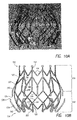
- Figure 7B illustrates the flat cut pattern of the frame shown in Figure 7A .
- the flat pattern can be cut from a metal tube and then the tube can be bent and expanded to the shape shown in Figure 7A .
- the frame 120 can further be expanded and/or compressed and/or otherwise worked to have the desired shape or shapes, such as for introduction and implantation.
- the frame when in an expanded configuration, such as in a fully expanded configuration, has a bulbous or slightly bulbous shape, with a middle portion being larger than the proximal 132 and distal 134 ends.
- the inside diameter of the both ends can be the same, or it can be bigger on one end than the other, while still having a middle portion larger than both the proximal and distal ends.
- the effective diameter of the distal frame end is smaller than the effective diameter of the middle portion.
- the bulbous shape of the frame can advantageously allow the frame to engage a native valve annulus or other body cavity, while spacing the inlet and outlet from the heart or vessel wall.
- the frame may not have a bulbous portion, and can have substantially the same outer dimension along its entire length, or it may have one end larger than the other end.
- the prosthesis 110 and frame 120 may be similar to the replacement heart valves and associated frames disclosed in U.S. Patent No. 8,403,983 and U.S. Publication Nos. 2010/0298931 , 2011/0313515 and 2012/0078353 the entireties of each of which are hereby incorporated by reference and made a part of this specification. This is inclusive of the entire disclosure and is not in any way limited to the disclosure of the replacement heart valves and associated frames.
- FIG. 7A illustrates the frame in an expanded configuration with a number of longitudinal struts 112 and undulating struts 114, with cells defined by the open spaces between the struts.
- the longitudinal struts may be arranged so that they are parallel or generally or substantially parallel to a longitudinal axis of the frame.
- the longitudinal axis of the frame may be defined as the central axis that extends through the center of the frame between the proximal 132 and distal 134 ends.
- Any number of configurations of struts can be used, such as the rings of undulating struts shown forming chevrons and diamonds, but also ovals, curves, and various other shapes.
- the illustrated embodiment includes two rings, or rows of chevrons shown in portion 116 and two rows of diamond-shaped cells shown in portion 118.
- the frame 120 has a non-foreshortening portion 116 and a foreshortening portion 118. These portions can be defined by the frame 120 and the positioning of various types of struts along the frame 120.
- the longitudinal struts 112 span the length of the non-foreshortening portion 116, while undulating struts 114 form the foreshortening portion 118.
- the struts 114 become more parallel with respect to the longitudinal axis of the frame, causing an outer diameter of the frame to decrease and the longitudinal length of the frame to increase in the foreshortening portion 118.
- the longitudinal length of the frame can decrease in the foreshortening portion 118. But, the frame length does not substantially change length in the non-foreshortening portion 116.
- Foreshortening of the frame 120 can be used to engage and secure the prosthesis to intralumenal tissue in a body cavity, for example tissue at or adjacent a native valve, such as a native valve annulus and/or leaflets.
- Opposing anchors 122, 124 can be constructed on the frame 120 so that portions of the anchors, such as tips or ends 126, 128, move closer together as the frame foreshortens. As one example, this can allow the anchors 122, 124 to grasp tissue on opposite sides of the native mitral annulus to thereby secure the prosthesis at the mitral valve.
- the anchors 122, 124 and anchor tips 126, 128 can be located anywhere along the frame 120 just so long as at least one of the anchors is either connected to the foreshortening portion 118 or the foreshortening portion is positioned between the anchors so that a portion of the anchors will be move closer together with expansion of the frame.
- the anchors 124 are connected to the foreshortening portion 118.
- the foreshortening portion can also be positioned anywhere along the frame, though it is shown towards the distal end 134.
- both of the anchor tips 126, 128 are located in the foreshortening portion 118.
- the foreshortening portion 118 may extend the entire length of the frame, such that there is no non-foreshortening portion 116.
- each of the anchors 122, 124 is positioned or extends generally radially outwardly from the frame 120 so that the anchor tips 126, 128 are generally spaced away or radially outward from the rest of the frame 120.
- the anchor tips may be located radially outward from the middle portion of the frame, with the tips 126 and 128 being axially spaced from one another.
- all or part of the structure connected to the anchor tip and extending radially from the frame, including one or more rings and/or struts can be considered part of the anchor.
- the anchors can include a base located on the anchor on a side opposite the tip. The base can be for example where the anchor begins to extend from or away from the frame 120.
- proximal anchors 122 are shown having first 136 and second 38 struts forming a chevron and connected to longitudinal struts 112 at a base of the anchor.
- the first and second struts of the anchor 122 are bent at the base so that the anchor 122 extends radially outwardly from the frame as it extends generally distally towards the tip 126.
- the first and second struts can be connected to each other at a radially outward location to form an outwardly extending loop, and in some embodiments, the first and second struts can be joined at a third strut 140 that continues to extend outwardly and/or generally distally.
- the third strut 140 is a short strut.
- the anchor also includes an eyelet 146. As illustrated, the eyelet is located at the distal end 126, though the eyelet can be positioned in other locations along the anchor 122.
- the tips 126 of the proximal anchors may extend distally and be parallel or substantially parallel with the longitudinal axis of the frame, or as illustrated in Figure 7A , the tips 126 may extend generally distally but still radially outwardly inclined or at an acute angle relative to the longitudinal axis of the frame.
- the distal anchors 124 are shown having looped ends 148.
- the looped ends can be larger near the tip to form a type of elongated teardrop.
- the tips 128 may be substantially flat.
- the looped end may assist the frame in not getting caught up on structures at or near the treatment location.
- each loop can be configured so that when the frame is deployed in-situ and expands, the movement of each loop from a delivered position to a deployed position can avoids getting caught on the papillary muscles.
- Each distal anchor 124 is connected to the frame at a base 142.
- the base of the distal anchor may be at a location where the corners of adjacent cells meet, such that the base is proximal to the distal end 134 of the frame.
- the base of the distal anchor may be at a distal most corner of a cell, which corresponds to a distal most point on the frame
- the distal anchors as illustrated extend from the base 142 generally distally before bending back around in an arcuate segment where the distal anchor extends generally proximally and radially outwardly from the frame.
- the anchors 124 may also generally distally and radially inwardly with respect to the frame such that the distal most point on the prosthesis has a smaller inside diameter than where the base 142 connects to the frame.
- the inside diameter at the distal most can be the same or substantially the same as the inside diameter of the proximal end, or may be smaller.
- the anchor as illustrated is bent around about 180 degrees so that the tip 128 extends in the opposite, proximal direction, which may be parallel or substantially parallel to the longitudinal axis of the frame.
- the distal anchors 124 are bent further inward such that the ends of the anchors point proximally and are generally parallel with the longitudinal axis of the frame.
- the tip 128 may extend generally proximally but still extend radially outwardly inclined or at an acute angle relative to the longitudinal axis of the frame
- each of the anchors can extend radially outwardly from the frame at an anchor base and terminate at an anchor tip.
- the anchors can be connected to the frame at one of many different locations including apices, junctions, other parts of struts, etc.
- the anchors can comprise first, second, third, or more spaced apart bending stages along the length of each anchor.
- the anchors can also extend either distally or proximally before and/or after one or more of the bending stages. A portion of the anchor may extend with the frame before or after any bending stages.
- FIG. 7A-B there are twelve distal anchors and twelve proximal anchors. In some embodiments there may be 116 anchors on one side and 112 on the other. Some embodiments may include different numbers of anchors. In addition, the distal and proximal anchors may be aligned so the tips point generally towards each other, or they may be spaced so that the tips point between two tips on the opposite side, as is illustrated in Figures 7A-B .
- the anchor tips 126 and 128 as described above advantageously provide atraumatic surfaces that may be used to grasp intralumenal tissue without causing unnecessary or undesired trauma to tissue.
- the proximal anchors tips 126 and distal anchor tips 128 may form flat, substantially flat, curved or other non-sharp surfaces to allow the tips to engage and/or grasp tissue, without necessarily piercing or puncturing through tissue.
- Figures 8A-9B show prostheses similar to that of Figures 7A-B with two different styles of distal anchors 124.
- the looped end 48' of the distal anchor is generally more elliptical with a curved tip as compared to the elongated teardrop shape of looped end 148 of Figures 7A-B . Otherwise the shape is substantially the same.
- the distal anchors 124 are looped anchors rather than having looped ends.
- the looped anchor has a first base 142 and a second base 144 connected to the frame, wherein the first and second bases are at opposite corners of the same cell. Alternatively, the first and second bases may be located at the distal most corners of adjacent cells.
- the distal anchors 124 extends generally distally from the frame at the first base 142 but then is bent back around and begins to extend outwardly from the frame in a generally proximal direction. The distal anchor 124 then repeats this configuration in reverse towards the second base 144 such that the two sides of the looped anchor are mirror images of one another. It will be understood that the looped anchor can have other configurations and that it may not be symmetrical.
- the tips 128 of the distal anchors are circumferentially aligned with the tips 126 of the proximal anchors, though in other embodiments, the tips 128 of the distal anchors may be circumferentially staggered between the tips 126 of the proximal anchors.
- adjacent distal anchors 126 are spaced apart by one cell, though in other embodiments, adjacent distal anchors may be provided on adjacent cells.
- the illustrated looped distal anchor of Figures 9A-B is made up of the following segments.
- the first segment 150 extends generally longitudinally with the frame, extending distally or generally distally (e.g., slightly radially inward) with the frame.
- the strut is then bent so that a second segment 152 extends generally parallel with an adjacent undulating strut 114.
- the strut is then bent so that a third segment 154 begins to extend generally longitudinally and distally or generally distally, and then is bent back around to point in generally the opposite direction (e.g., in a proximal direction parallel or generally parallel with the longitudinal axis of the frame).
- the third segment 154 ends in the rounded tip 128 and then the anchor strut repeats to form the mirror image. After the third segment 154 bends back around to point in generally the opposite direction, in the embodiment illustrated the third segment may first extend radially outward at an acute angle relative to the longitudinal axis before bending into a portion that extends parallel or substantially parallel to the longitudinal axis.
- the paired third segments 154 extend parallel or generally parallel with one another from the second segment to the tip, though they may also move slightly towards or away from each other in some embodiments.
- Figures 10A-B show a prosthesis similar to Figures 9A-B that also has looped distal anchors.
- the first segment 150 extends longitudinally in a distal direction from the frame and the strut is bent back on itself to point generally in the opposite (e.g., proximal) direction.
- the second segment is bent inward before extending parallel or generally parallel with its mirror image on the other side forming a nose and wing configuration similar to the shape of certain bicycle seats.
- the proximal anchors 122 also have an elongated third strut 140.
- the proximal anchor 122 is shown having first 136 and second 138 struts forming a chevron and connected to longitudinal struts 112 at a base of the anchor.
- the first and second struts of the anchor 122 are bent at the base so that the anchor 122 extends radially outwardly from the frame as it extends towards the tip 126.
- the first and second struts join at a third strut 140 that continues to extend outwardly and is then bent such that the tip points distally and extends in a manner parallel or generally parallel with the longitudinal axis of the frame.
- the proximal anchor may or may not include an eyelet 146 along its length.
- the distal tip of the proximal anchors may have an atraumatic surface, such as an enlarged circular or curved end as illustrated.
- the distal anchors 124 may have tips 1 128 that are positioned radially outward of the tips 126 of the proximal anchors 122.
- Other embodiments may have the tips 126 being positioned outward of the tips 128.
- Such configurations are also possible with the other frames and prostheses described elsewhere herein.
- Figure 11 illustrated an embodiment similar to the prosthesis of Figure 10B with twelve distal anchors instead of six. Because of this change, in one embodiment two anchors share the first segment 150 where the anchor base 142, 144 is connected to the frame. As illustrated, each of the proximal and distal anchors may be circumferentially aligned with each other, and each of the distal anchors corresponds to one of the cells
- a prosthesis can include one or more of a valve 1 60, a skirt 170 and a support band 180.
- the prosthesis can be a replacement heart valve similar to that and including features similar to those disclosed in U.S. Patent Appl. Nos. 13/165,721, filed June 21, 2011 , published as U.S. 2011/0313515 ; and 13/244,080, filed September 23, 2011 , published as 2012/0078353.
- the entire contents of both applications are hereby incorporated by reference herein and made a part of this specification. This is inclusive of the entire disclosure and is not in any way limited to the disclosure of the replacement heart valve.
- the valve 160 can be a replacement heart valve which includes a plurality of valve leaflets 162.
- the plurality of valve leaflets 162 can function in a manner similar to the natural mitral valve, or to other valves in the vascular system.
- the plurality of valve leaflets 162 can open in a first position and then engage one another to close the valve in a second position.
- the plurality of valve leaflets 162 can be made to function as a one way valve such that flow in one direction opens the valve and flow in a second direction opposite the first direction closes the valve.
- the replacement heart valve 160 can be constructed so as to open naturally with the beating of the heart. For example, the plurality of valve leaflets 162 can open during diastole and close during systole.
- the leaflets 162 can be coupled to a skirt 170.
- the proximal ends of the leaflets 162 can be connected to a proximal end of the skirt 170.
- the skirt 170 can be used to at least partially control how fluid flows through and/or around the valve 160.
- the skirt 170 can surround at least a portion of the valve and be connected to the valve leaflets 162.
- the skirt 170 can form an inner wall connected to and positioned within the frame 120.
- the skirt 170 can also be made to move with the foreshortening portion 118 of the frame 120.
- the skirt 170 can extend the length of the frame 120 or it can extend along only part of the length of the frame 120.
- the ends of the heart valve 160 can coincide with ends of the skirt 170.
- one or more of the ends of the frame 120 can coincide with the ends of the skirt 170.
- the proximal end of the skirt 170 and heart valve 160 are sewn together.
- the skirt 170 can not only extend to the distal end of the frame 20 but can also extend to the outside of the frame and is shown wrapped around each of the distal anchors 124.
- valve 160 and skirt 170 Other shapes and configurations can also be used for the valve 160 and skirt 170.
- the skirt 170 may extend along the length of the leaflets 162, but is not connected to them. In the illustrated embodiments, the skirt 170 is attached to the frame 120 and the leaflets 162 are attached to the skirt 170.
- the skirt 170 can be constructed in multiple different ways.
- the skirt 170 can be made of knit polyester or another stretchable or flexible fabric.
- the skirt 170 is made from a material that is more flexible than the valve leaflet material.
- the distal and/or proximal end of the skirt 170 can be straight, curved, or have any other desired configuration.
- the skirt 170 is shown with undulations patterned to generally correspond to the undulations at the distal end 134 of the frame 120. It can be seen that the skirt 170 wraps around the struts at the distal end.
- the skirt 170 can be formed of one piece or multiple pieces.
- the skirt 170 attached to the valve 160 can be one piece and then each distal anchor can be covered by a separate piece of material of the skirt 170. This is illustrated in Figure 12A as one of the distal anchors on the back side remains uncovered. In addition, Figure 12C shows the distal anchors uncovered. It is to be understood that other configurations of the skirt 170 can also be employed. For example, the anchors may remain uncovered, or only a portion may be covered.
- skirt 170 another embodiment of the skirt 170 is shown.
- the skirt extends past the frame and is then wrapped around it.
- the skirt 170 extends from the inside of the frame 120 to the outside of the frame.
- the skirt can extend completely around the frame for 1/4, 1/3, 1/2, or more of the length of the distal anchors.
- the skirt can also cover the distal anchors 124.
- the skirt is a one piece skirt, but it will be understood that the skirt can be made of multiple pieces.
- the skirt 170 and particularly portions that cover the distal anchors 124, can beneficially be used to help prevent leakage of blood flow around the heart valve.
- the skirt can encourage tissue in-growth between the skirt and the natural tissue. This may further help to prevent leakage of blood flow around the heart valve.
- the prosthesis 110 can also include a support band 180 as is shown in Figures 12A-13B .
- the support band 180 may be placed or positioned around or within the frame 120 at the proximal end 132.
- the support band 180 can be used to reinforce and/or constrain the frame 120.
- the support band 180 can help to control the expansion of the frame 120 from the compacted to the expanded state.
- the support band 180 can also be used to reduce the amount of motion that occurs at the proximal end 132 after the prosthesis 110 has been implanted at the mitral heart valve or other location.
- the support band 80 may comprise a polyester fabric band.
- the support band 180 may comprise a no-stretch or limited stretch material.
- the support band 180 is not made of an elastic material or a material known to have high elasticity.
- the support band 180 is made from a material that is less flexible than the valve skirt material and/or the valve leaflet material.
- the distal and proximal ends of the support band 180 can be straight, curved, undulating with the undulations of frame, or any other desired configuration.
- the support band 180 can be connected to the valve frame with a plurality of stitches, loops, knots, staples, or other types of connections.
- the frame 120 can be sandwiched between two sides or layers of the support band 180.
- the support band 180 is a single layer positioned within and attached to the frame 120 with a plurality of stitches around one or more of the longitudinal and/or undulating struts.
- the support band 80 can be attached to the proximal end of the valve skirt 140.
- Figures 14A-D show a prosthesis similar to that of Figures 10A-B with a different style and configuration of distal anchor 124.
- the distal anchors are shorter than and spaced radially inward from the distal anchors of Figures 10A-B .
- the distal anchors 124 are not positioned as far radially outward as the proximal anchors, and the tips 128 may be positioned radially inward of the tips 126.
- such a configuration may be advantageous in positioning and securing the prosthesis in a mitral valve or other body location.
- the distal anchors 124 may comprise loops as described above, having a curved or arcuate atraumatic tip to minimize damage to body tissue.
- Figures 15A-D show an embodiment of a prosthesis where the distal anchors do not comprise loops, but instead comprise single struts each extending distally from the corners where adjacent cells meet.
- these anchors may first extend distally or generally distally, and may further extend radially inward, before bending around to extend proximally or generally proximally, such as at an acute angle relative to the longitudinal axis of the frame.
- the tips 128 of the anchors may comprise an atraumatic surface, such as a flattened or curved enlarged tip. As illustrated, the tips 128 may be circumferentially staggered between tips 1 126 of the proximal anchors 122, as best shown in Figures 15C and 15D.
- Figures 15C-D also show the frame 120 having a valve 160 and skirt 170 attached as described above.
- any of the prostheses 110 described above may be deployed into a heart valve annulus, and positioned when compacted so that the anchor tips 126, 128 of the opposing anchors 122, 124 are disposed on opposite sides of the native annulus 188 as shown in Figures 16A and 16B A .
- the opposing anchors are drawn closer together so as to grasp tissue on opposite sides of the native annulus 188 and securely hold the replacement heart valve 110 in position.
- the replacement heart valve 110 can be held securely in position without requiring a substantial radial force against the native annulus. Because the anchor tips are preferably atraumatic, the grasping or engaging of tissue by the prosthesis minimizes damage to the native tissue.
- the foreshortening portion 118 can be used to move the anchor tips 126, 128 closer together as the replacement heart valve 110 moves to the expanded position to thereby engage the native valve annulus.
- the prosthesis can be deployed into a heart valve or otherwise deployed in manners similar to those described with respect to a replacement heart valve in U.S. Publication No. 2010/0298931 and 2012/0078353 the entireties of each of which are hereby incorporated by reference and made a part of this specification. This is inclusive of the entire disclosure and is not in any way limited to the disclosure related to deployment of a replacement heart valve.
- FIGS 16A and 16B show a schematic representation of the replacement heart valve 110 installed in a human heart 184.
- the heart is shown in cross-section, and represents typical anatomy, including a left atrium 178 and left ventricle 186.
- the left atrium 178 and left ventricle 186 communicate with one another through a mitral annulus 188.
- Also shown schematically is a native anterior mitral leaflet 190 having chordae tendineae 192 that connect a downstream end of the anterior mitral leaflet 190 and to the left ventricle 186.
- a method is provided of delivering a replacement valve to a native mitral valve and atraumatically securing the replacement valve relative to the native mitral valve annulus 188.
- the replacement valve can be mounted on a delivery device and delivered to the native mitral valve annulus while the replacement valve is in a radially compacted state.
- the replacement valve may be positioned so that the ends or tips of the distal anchors are on a ventricular side of the native leaflets 190 beyond a location where chordae tendineae 192 connect to free ends of the native leaflets. At least a portion of the replacement valve can be released from the delivery device to thereby expand the distal anchors radially outwardly.
- the distal anchors may extend between at least some of the chordae.
- the distal anchors (along with the frame) can be moved toward the ventricular side of the native valve annulus with the distal anchors extending between at least some of the chordae tendineae to provide tension on the chordae tendineae.
- the replacement valve With tension provided on the chordae tendineae, the replacement valve can be further released from the delivery device to thereby expand the proximal anchors radially outwardly.
- the proximal anchors upon further release of the replacement valve from the delivery device can move into engagement with tissue on an atrial side of the native valve annulus, such as with the atrial side of the native valve annulus.
- the method just described may utilize any of the prostheses herein described, but may be particularly suitable for the prosthesis of Figures 14A-14D where the ends of the distal anchors are not positioned as far out radially as the ends of the proximal anchors when the frame is expanded.
- the distal anchors may have a suitable length for extending between and providing tension on the chordae tendineae, but need not and may in some embodiments not engage tissue with the tips 128.
- the some or all of the distal anchors remain spaced from tissue on the ventricular side of the native valve annulus after delivery and expansion.
- the interaction between the distal anchors and the chordae tendineae may therefore be sufficient to secure the distal end of the prosthesis, while the engagement of the proximal anchors with tissue on the atrial side of the native valve annulus will help further secure and orient the prosthesis
- the distal anchors may comprise loops, such as any of the looped structures previously described.
- the distal anchors may also be covered with a resilient material such as described above for the skirt 170 that promotes tissue growth with adjacent body tissue. Such material may also be useful to prevent paravalvular leakage.
- the atraumatic distal anchors may advantageously prevent snagging of the prosthesis on internal structures, such as the papillary muscles.
Abstract
Description
- Certain embodiments disclosed herein relate generally to prostheses for implantation within a lumen or body cavity. In particular, certain embodiments relate to expandable prostheses such as replacement heart valves, such as for the mitral valve, that are configured to atraumatically grasp intralumenal tissue.
- Human heart valves, which include the aortic, pulmonary, mitral and tricuspid valves, function essentially as one-way valves operating in synchronization with the pumping heart. The valves allow blood to flow downstream, but block blood from flowing upstream. Diseased heart valves exhibit impairments such as narrowing of the valve or regurgitation, which inhibit the valves' ability to control blood flow. Such impairments reduce the heart's blood-pumping efficiency and can be a debilitating and life threatening condition. For example, valve insufficiency can lead to conditions such as heart hypertrophy and dilation of the ventricle. Thus, extensive efforts have been made to develop methods and apparatuses to repair or replace impaired heart valves.
- Prostheses exist to correct problems associated with impaired heart valves. For example, mechanical and tissue-based heart valve prostheses can be used to replace impaired native heart valves. More recently, substantial effort has been dedicated to developing replacement heart valves, particularly tissue-based replacement heart valves that can be delivered with less trauma to the patient than through open heart surgery. Replacement valves are being designed to be delivered through minimally invasive procedures and even percutaneous procedures. Such replacement valves often include a tissue-based valve body that is connected to an expandable frame that is then delivered to the native valve's annulus.
- Development of prostheses including but not limited to replacement heart valves that can be compacted for delivery and then controllably expanded for controlled placement has proven to be particularly challenging. An additional challenge relates to the ability of such prostheses to be secured relative to intralumenal tissue, e.g., tissue within any body lumen or cavity, in an atraumatic manner. Further challenges arise when trying to controllably deliver and secure such prostheses in a location such as at a native mitral valve. These replacement valves are often intended to at least partially block blood flow. However, a problem occurs when blood flows around the valve on the outside of the prosthesis. For example, in the context of replacement heart valves, paravalvular leakage has proven particularly challenging.
- Embodiments of the present disclosure are directed to a prosthesis, such as but not limited to a replacement heart valve. Further embodiments are directed to methods of delivering a prosthesis into a body cavity and/or securing a prosthesis to intralumenal tissue. In some embodiments, a replacement heart valve and methods for delivering a replacement heart valve to a native heart valve, such as a mitral valve, are provided.
- In some embodiments, a prosthesis can comprise an expandable frame, and a plurality of anchors, for example a plurality of proximal anchors and a plurality of distal anchors. The expandable frame may comprise a proximal end and a distal end and having a longitudinal axis extending between the proximal end and the distal end. The anchors can extend outwardly from the frame. The frame can be configured to radially expand and contract for deployment within the body cavity.
- In some embodiments, the frame comprises a plurality of foreshortening cells causing a longitudinal length of the frame to decrease as the frame moves from a collapsed size to an expanded size. In some embodiments, proximal anchors and distal anchors may be separated by a foreshortening portion of the frame. In some embodiments, some of the plurality of anchors may be connected to a non-foreshortening portion of the frame, and some of the plurality of anchors are connected to a foreshortening portion of the frame.
- In some embodiments, when the frame is in an expanded configuration, the frame can have a larger cross-sectional dimension in a middle portion of the frame and a smaller cross-sectional dimension in a proximal portion and a distal portion of the frame, wherein the middle portion is between the proximal and distal portions. In other embodiments, the frame may have a cylindrical or substantially cylindrical shape when in an expanded configuration, wherein the proximal end and the distal end of the frame have the same or substantially the same cross-sectional dimension.
- In some embodiments, at least some of the anchors, or alternatively all of the anchors, comprise a loop that forms an atraumatic end of a corresponding anchor. For example, proximal anchors and/or distal anchors may comprise looped ends. In some embodiments, the anchors having looped ends may connect to the frame at spaced apart base locations. For example, the spaced apart locations may be at opposite corners of the same cell of a frame. Additionally or alternatively, at least some anchors which may or may not have looped ends may connect to the frame with a single strut. Adjacent ends of anchors may be circumferentially spaced apart by one or more cells of the frame. In some embodiments, when the frame is in an expanded configuration, a width of each of the plurality of anchors having looped ends as defined circumferentially around the longitudinal axis over the entire length of the anchor from the base to the looped end is less than the width of one cell of the frame. In some embodiments, the looped ends of each anchor may be circumferentially aligned with the base where the anchor connects to the frame so that the looped end and the base are both located within a common plane that is parallel to and intersects the longitudinal axis.
- In some embodiments, the base of each of the plurality of proximal and/or distal anchors is at a location where corners of two adjacent cells of the frame meet. In some embodiments, the base of each of the plurality of distal anchors is at a distalmost corner of a cell. In some embodiments, the base of each of the plurality of proximal anchors is at a proximalmost corner of a cell. In some embodiments, the ends of the plurality of distal anchors are not circumferentially aligned with the ends of the plurality proximal anchors when the frame is in an expanded configuration.
- A prosthesis according to certain embodiments can comprise a plurality of proximal anchors connected to the frame so that when the frame is in an expanded configuration an end of each proximal anchor is positioned radially outward from the frame and extends generally distally. Alternatively or in addition, a plurality of distal anchors may be connected to the frame so that when the frame is in an expanded configuration an end of each distal anchor is positioned radially outward from the frame and extends generally proximally. The ends of the distal anchors may be axially spaced from the ends of the proximal anchors when the frame is in an expanded configuration. In some embodiments, the frame is configured such that radial expansion of the frame causes the ends of the plurality of proximal anchors and the ends of the plurality of distal anchors to draw closer together.
- In some embodiments, a plurality of proximal anchors may extend from the frame and be expandable from a collapsed configuration to an expanded configuration, wherein in the expanded configuration, each proximal anchor extends proximally away from the proximal end of the frame and then turns to extend distally, each proximal anchor extending to an end positioned radially outward from the frame. The plurality of proximal anchors may in some embodiments extend from or a near the proximal end of the frame. The ends of the proximal anchors may be distal to the proximal end of the frame or distal to where the proximal anchors connect to the frame when the frame is at least partially expanded and the proximal anchors are in their expanded configuration.
- In some embodiments, a plurality of distal anchors may extend from the frame and be expandable from a collapsed configuration to an expanded configuration, wherein in the expanded configuration, each distal anchor extends distally away from the distal end of the frame and then turns to extend proximally, each distal anchor extending to an end positioned radially outward from the frame. The plurality of distal anchors may in some embodiments extend from or a near the distal end of the frame. The ends of the distal anchors may be proximal to the distal end of the frame or distal to where the distal anchors connect to the frame when the frame is at least partially expanded and the distal anchors are in their expanded configuration.
- In some embodiments, the frame and the plurality of anchors (for example the plurality of proximal anchors and the plurality of distal anchors) are formed from a single piece of material. For example, the frame, the plurality of proximal anchors and the plurality of distal anchors may be formed by laser cutting a metal tube.
- In some embodiments, the ends of at least some of the proximal anchors and/or distal anchors are substantially parallel with the longitudinal axis when the frame is at least partially expanded and the proximal and distal anchors are in their expanded configurations. Alternatively or additionally, the ends of at least some of the proximal anchors and/or distal anchors may be substantially perpendicular with the longitudinal axis when the frame is at least partially expanded and the proximal and distal anchors are in their expanded configurations. Alternatively or additionally, the ends of at least some of the proximal anchors and/or distal anchors may be inclined with respect to the longitudinal axis when the frame is at least partially expanded and the proximal and distal anchors are in their expanded configurations.
- In some embodiments, some of the anchors expand to a first radial distance, and some of the anchors expand to a second radial distance, the first radial distance being greater than the second radial distance. For example, at least some of the plurality of proximal anchors may expand to a first radial distance, and at least some of the plurality of distal anchors may expand to a second radial distance, the first radial distance being greater than the second radial distance. Alternatively, at least some of the plurality of distal anchors may expand to a first radial distance, and at least some of the plurality of proximal anchors may expand to a second radial distance, the first radial distance being greater than the second radial distance.
- Some embodiments of the prosthesis further comprise a valve body attached to the expandable frame. A replacement mitral valve may also be provided that comprises any of the prostheses described herein. The frame of a prosthesis may be positionable within a native mitral valve such that proximal anchors atraumatically engage tissue on an atrial side of the native mitral valve annulus, and distal anchors are positionable within the ventricle and have portions that extend generally proximally toward a ventricular side of the native mitral valve annulus. The distal anchors may be positionable within the ventricle and extend proximally to ends spaced distally from the native mitral valve annulus. Alternatively, the distal anchors may be positionable within the ventricle and extend proximally to ends that engage the native mitral valve annulus.
- In some embodiments, the frame may be configured so that it does not apply significant radial force to the native valve annulus to thereby permit the frame to axially reciprocate relative to the native mitral valve annulus. In some embodiments, at least some of the plurality of anchors are configured to expand to a radial distance from a central longitudinal axis of the frame that is about 150% or more of a radius of the frame when the frame is in an expanded configuration. In some embodiments, at least some of the plurality of anchors are configured to expand to a radial distance from the central longitudinal axis that is about 180% or more of the radius of the frame when the frame is in an expanded configuration.
- In some embodiments, a prosthesis may further comprise an outer skirt surrounding the frame. The outer skirt may be connected to or near at least some of the ends of the anchors (e.g., the proximal anchors) and configured to move radially outward with the anchors when the anchors move from a collapsed configuration to an expanded configuration. The outer skirt is configured to prevent paravalvular leakage exterior to the frame when the anchors are in an expanded configuration.
- Methods of delivering a prosthesis and/or securing the prosthesis to intralumenal tissue, and use of a prosthesis to secure to intraluminal tissue, for example as a replacement heart valve to secure to a mitral valve or other annulus, are also provided. In one embodiment, a method of delivering a replacement valve to a native mitral valve can comprise one or more of the following steps. Delivering a replacement valve mounted on a delivery device to the native mitral valve annulus while the replacement valve is in a radially compacted state, the replacement valve comprising a radially expandable frame comprising a proximal end, a distal end, a plurality of distal anchors extending generally proximally from the frame, and a plurality of proximal anchors extending generally distally from the frame. Positioning the replacement valve so that ends of the distal anchors are on a ventricular side of the native leaflets beyond a location where chordae tendineae connect to free ends of the native leaflets. Releasing at least a portion of the replacement valve from the delivery device to thereby expand the distal anchors radially outwardly to a first radial dimension. Moving the ends of the distal anchors toward the ventricular side of the native valve annulus with the distal anchors extending between at least some of the chordae tendineae to provide tension on the chordae tendineae. Further releasing the replacement valve from the delivery device to thereby expand the proximal anchors radially outwardly to a second radial dimension greater than the first radial dimension, wherein the proximal anchors upon further release of the replacement valve from the delivery device move into engagement with tissue on an atrial side of the native valve annulus while the distal anchors provide tension on the chordae tendineae.
- In some embodiments a prosthesis can comprise an expandable frame, a plurality of distal anchors and a plurality of proximal anchors. The anchors can extend outwardly from the frame. The frame can be configured to radially expand and contract for deployment within the body cavity. When the frame is in an expanded configuration, the proximal anchors can extend a significant distance away from the exterior of the frame, such as a length of about one-half or more the diameter of the frame. In some embodiments, at least some of the anchors comprise a loop that forms an atraumatic end of a corresponding anchor. In some embodiments, an outer skirt may be positioned annularly around an exterior of the expandable frame and be connected to some of the anchors to create an axial barrier to fluid flow exterior to the frame when deployed within the body cavity.
- Further embodiments are directed to methods of delivering a prosthesis, e.g. a replacement heart valve, methods of securing a prosthesis to intralumenal tissue, and methods of using a prosthesis to create a barrier to fluid flow exterior to the prosthesis (e.g., to prevent paravalvular leakage).
- In some embodiments, a prosthesis can be configured to grasp intralumenal tissue when deployed within a body cavity. The prosthesis can comprise an expandable frame, a plurality of proximal anchors connected to the frame, and a plurality of distal anchors connected to the frame. The expandable frame can comprise a proximal end and a distal end and a longitudinal axis extending therethrough, the frame configured to collapse radially for delivery and to expand radially upon deployment. The plurality of proximal anchors can be expandable to a configuration wherein a portion of each of the proximal anchors extends generally distally and an end of each of the proximal anchors is positioned radially outward from the frame. The plurality of distal anchors can be expandable to a configuration wherein a portion of each of the distal anchors extends generally proximally and an end of each of the distal anchors is positioned radially outward from the frame. Expansion of the frame from a first at least partially collapsed size to a second expanded size can cause the ends of the proximal anchors and the ends of the distal anchors to draw closer together. At least some of the plurality of proximal anchors can be configured to expand to a radial distance from a central longitudinal axis of the frame that is about 150% or more of a radius of the frame when the frame is in an expanded configuration.
- The following numbered embodiments are also intended to be encompassed by the present disclosure:
- 1. A prosthesis configured to grasp intralumenal tissue when deployed within a body cavity, the prosthesis comprising:
- an expandable frame comprising a proximal end and a distal end and a longitudinal axis extending therethrough, the frame configured to collapse radially for delivery and to expand radially upon deployment;
- a plurality of proximal anchors extending from the frame and expandable from a collapsed configuration to an expanded configuration, wherein in the expanded configuration, each proximal anchor extends proximally away from the proximal end of the frame and then turns to extend distally, each proximal anchor extending to an end positioned radially outward from the frame; and
- a plurality of distal anchors extending from the frame and expandable from a collapsed configuration to an expanded configuration, wherein in the expanded configuration, each distal anchor extends distally away from the distal end of the frame and then turns to extend proximally, each distal anchor extending to an end positioned radially outward from the frame.
- 2. The prosthesis of Embodiment 1, wherein at least some of the proximal anchors and/or distal anchors comprise looped ends.
- 3. The prosthesis of Embodiment 1, wherein all of the plurality of proximal anchors and the plurality of distal anchors comprise looped ends.
- 4. The prosthesis of any one of Embodiments 2-3, wherein at least some of the anchors comprising looped ends are connected to the frame at a first base and a second base spaced apart from each other.
- 5. The prosthesis of any one of Embodiments 2-4, wherein at least some of the anchors comprising looped ends are connected to the frame by a single strut.
- 6. The prosthesis of any one of Embodiments 1-5, wherein the frame, the plurality of proximal anchors and the plurality of distal anchors are formed from a single piece of material.
- 7. The prosthesis of any one of Embodiments 1-6, wherein the frame comprises a plurality of foreshortening cells causing a longitudinal length of the frame to decrease as the frame moves from a collapsed size to an expanded size.
- 8. The prosthesis of any one of Embodiments 1-7, wherein the proximal anchors and distal anchors are separated by a foreshortening portion of the frame.
- 9. The prosthesis of any one of Embodiments 1-8, wherein the ends of at least some of the proximal anchors and/or distal anchors are substantially parallel with the longitudinal axis when the frame is at least partially expanded and the proximal and distal anchors are in their expanded configurations.
- 10. The prosthesis of any one of Embodiments 1-9, wherein the ends of at least some of the proximal anchors and/or distal anchors are substantially perpendicular with the longitudinal axis when the frame is at least partially expanded and the proximal and distal anchors are in their expanded configurations.
- 11. The prosthesis of any one of Embodiments 1-10, wherein some of the anchors expand to a first radial distance, and some of the anchors expand to a second radial distance, the first radial distance being greater than the second radial distance.
- 12. The prosthesis of any one of Embodiments 1-11, wherein at least some of the plurality of proximal anchors expand to a first radial distance, and at least some of the plurality of distal anchors expand to a second radial distance, the first radial distance being greater than the second radial distance.
- 13. A replacement mitral valve comprising the prosthesis of any one of Embodiments 1-12, wherein when the frame in an expanded configuration, the frame is positionable within a native mitral valve annulus such that:
- the proximal anchors atraumatically engage tissue on an atrial side of the native mitral valve annulus; and
- the distal anchors are positionable within the ventricle and have portions that extend generally proximally toward a ventricular side of the native mitral valve annulus.
- 14. The replacement mitral valve of Embodiment 13, wherein the distal anchors are positionable within the ventricle and extend proximally to ends spaced distally from the native mitral valve annulus.
- 15. The replacement mitral valve of Embodiment 13, wherein the distal anchors are positionable within the ventricle and extend proximally to ends that engage the native mitral valve annulus.
- 16. A prosthesis configured to grasp intralumenal tissue when deployed within a body cavity, the prosthesis comprising:
- an expandable frame comprising a proximal end and a distal end and a longitudinal axis extending therethrough, the frame configured to collapse radially for delivery and to expand radially upon deployment;
- a plurality of proximal anchors connected to the frame and expandable to a configuration wherein a portion of each of the proximal anchors extends generally distally and an end of each of the proximal anchors is positioned radially outward from the frame;
- a plurality of distal anchors connected to the frame and expandable to a configuration wherein a portion of each of the distal anchors extends generally proximally and an end of each of the distal anchors is positioned radially outward from the frame;
- wherein at least some of the plurality of proximal anchors are configured to expand to a radial distance from a central longitudinal axis of the frame that is about 150% or more of a radius of the frame when the frame is in an expanded configuration.
- 17. The prosthesis of
Embodiment 16, wherein expansion of the frame from a first at least partially collapsed size to a second expanded size causes the ends of the proximal anchors and the ends of the distal anchors to draw closer together. - 18. The prosthesis of
Embodiment 16 or 17, wherein the frame comprises a plurality of foreshortening cells causing a longitudinal length of the frame to decrease as the frame moves from a collapsed size to an expanded size. - 19. The prosthesis of any one of Embodiments 16-18, wherein the proximal anchors and distal anchors are separated by a foreshortening portion of the frame.
- 20. The prosthesis of any one of Embodiments 16-19, wherein at least some of the proximal anchors are configured to expand to a radial distance from the central longitudinal axis that is about 180% or more of the radius of the frame when the frame is in an expanded configuration.
- 21. The prosthesis of any one of Embodiments 16-19, wherein at least some of the proximal anchors are configured to expand to a radial distance from an exterior surface of the frame that is about ½ or more an expanded diameter of the frame.
- 22. The prosthesis of any one of Embodiments 16-21, wherein the frame, the plurality of proximal anchors and the plurality of distal anchors are formed from a single piece of material.
- 23. The prosthesis of any one of Embodiments 16-22, wherein at least some of the anchors when in their expanded configuration extend in a first direction away from an end of the frame before turning in a second direction opposite the first direction.
- 24. The prosthesis of any one of Embodiments 16-23, wherein some of the anchors expand to a first radial distance, and some of the anchors expand to a second radial distance, the first radial distance being greater than the second radial distance.
- 25. The prosthesis of any one of Embodiments 16-24, wherein at least some of the plurality of proximal anchors expand to a first radial distance, and at least some of the plurality of distal anchors expand to a second radial distance, the first radial distance being greater than the second radial distance.
- 26. The prosthesis of any one of Embodiments 16-25, wherein at least some of the plurality of anchors comprise looped ends.
- 27. The prosthesis of any one of Embodiments 16-26, wherein all of the plurality of proximal and distal anchors comprise looped ends.
- 28. The prosthesis of any one of Embodiments 16-27, wherein the ends of at least some of the anchors are substantially parallel with the longitudinal axis of the frame when the anchors are in their expanded configuration.
- 29. The prosthesis of any one of Embodiments 16-28, wherein the ends of at least some of the anchors are substantially perpendicular with the longitudinal axis of the frame when the proximal anchors are in their expanded configuration.
- 30. The prosthesis of any one of Embodiments 16-29, further comprising a valve body attached to the expandable frame.
- 31. The prosthesis of any one of Embodiments 16-30, further comprising an outer skirt that extends radially outward from the frame and that is connected at or near the ends of at least some of the anchors when the frame is in an expanded configuration.
- 32. The prosthesis of Embodiment 31, wherein the outer skirt extends radially outward from the frame and is connected at or near the ends of at least some of the proximal anchors.
- 33. The prosthesis of
Embodiment 32, wherein the outer skirt extends radially outward from the frame from a location on the frame distal to the ends of the proximal anchors. - 34. The prosthesis of any one of Embodiments 16-30, further comprising an outer skirt surrounding the frame, the outer skirt connected to or near at least some of the ends of the proximal anchors and configured to move radially outward with the proximal anchors when the proximal anchors move from a collapsed configuration to an expanded configuration, the outer skirt configured to prevent paravalvular leakage exterior to the frame when the proximal anchors are in an expanded configuration.
- 35. The prosthesis of any one of Embodiments 16-34, wherein the frame has a substantially cylindrical shape with a substantially constant cross-sectional dimension from the proximal end to the distal end.
- 36. The prosthesis of any one of Embodiments 16-35, wherein the plurality of proximal anchors extend from or near the proximal end of the frame.
- 37. The prosthesis of any one of Embodiments 16-36, wherein the plurality of distal anchors extend from or near the distal end of the frame.
- 38. A replacement mitral valve comprising the prosthesis of any one of Embodiments 16-37, wherein when the frame in an expanded configuration, the frame is positionable within a native mitral valve annulus such that:
- the proximal anchors atraumatically engage tissue on an atrial side of the native mitral valve annulus; and
- the distal anchors are positionable within the ventricle and have portions that extend proximally toward a ventricular side of the native mitral valve annulus.
- 39. The replacement mitral valve of Embodiment 38, wherein when the frame is in an expanded configuration within the native mitral valve annulus, the frame does not apply significant radial force to the native valve annulus to thereby permit the frame to axially reciprocate relative to the native mitral valve annulus.
- These and other features, aspects and advantages are described below with reference to the drawings, which are intended to illustrate but not to limit the invention. In the drawings, like reference characters denote corresponding features consistently throughout similar embodiments.
-
Figure 1A is a side view of a frame for a prosthesis. -
Figure 1B is a top perspective view of the frame ofFigure 1A where the anchors have not yet been bent to the desired shape. -
Figure 2 is an embodiment of a prosthesis configured as a replacement heart valve. -
Figure 3 is an embodiment of a prosthesis configured as a replacement heart valve. -
Figure 4 is an embodiment of a prosthesis configured as a replacement heart valve. -
Figure 5 is a schematic representation of a prosthesis positioned within the heart. -
Figure 6 is a detail schematic representation of the prosthesis positioned within the heart ofFigure 5 . -
Figure 7A is a side view of an embodiment of a prosthesis. -
Figure 7B is a flat pattern view of the prosthesis ofFigure 7A . -
Figure 8A is a side view of an embodiment of a prosthesis. -
Figure 8B is a flat pattern view of the prosthesis ofFigure 8A . -
Figure 9A is a side view of an embodiment of a prosthesis. -
Figure 9B is a flat pattern view of the prosthesis ofFigure 9A . -
Figure 10A is a side view of an embodiment of a prosthesis. -
Figure 10B is a side view of the prosthesis ofFigure 10A . -
Figure 11 is a side view of an embodiment of a prosthesis. -
Figure 12A is a side view of an embodiment of a prosthesis configured as a replacement heart valve. -
Figure 12B is a side view of the prosthesis ofFigure 12A . -
Figure 12C is a bottom view of a prosthesis similar to the embodiment ofFigure 6A . -
Figure 12D is a bottom view of the prosthesis ofFigure 12B . -
Figure 13A is a side view of an embodiment of a prosthesis configured as a replacement heart valve. -
Figure 13B is a side view of the prosthesis ofFigure 13A . -
Figure 14A is a side view of an embodiment of a prosthesis. -
Figure 14B is a side view of the prosthesis ofFigure 14A . -
Figure 14C is a detail view of a portion of the prosthesis ofFigure 14A . -
Figure 14D is a detail view of a portion of the prosthesis ofFigure 14A . -
Figure 15A is a side view of an embodiment of a prosthesis. -
Figure 15B is a side view of the prosthesis ofFigure 15A . -
Figure 15C is a bottom view of the prosthesis ofFigure 15A , configured as a replacement heart valve. -
Figure 15D is a bottom view of the prosthesis ofFigure 15A , configured as a replacement heart valve. -
Figure 16A is a schematic representation of a prosthesis positioned within the heart. -
Figure 16B is a detail schematic representation of the prosthesis positioned within the heart ofFigure 16A . - The present specification and drawings provide aspects and features of the disclosure in the context of several embodiments of prostheses, replacement heart valves, delivery devices and methods that are configured for use in the vasculature of a patient, such as for replacement of natural heart valves in a patient. These embodiments may be discussed in connection with replacing specific valves such as the patient's aortic or mitral valve. However, it is to be understood that the features and concepts discussed herein can be applied to products other than heart valve implants. For example, the controlled positioning, deployment, and securing features described herein can be applied to medical implants, for example other types of expandable prostheses, for use elsewhere in the body, such as within a vein, or the like. In addition, particular features of a valve, delivery device, etc. should not be taken as limiting, and features of any one embodiment discussed herein can be combined with features of other embodiments as desired and when appropriate.
- With initial reference to
Figures 1A-B , an embodiment of aprosthesis 10 is shown. The illustratedprosthesis 10 includes aframe 20 that may be self-expanding or balloon expandable. Theframe 20 can include aproximal end 32, adistal end 34 and proximal 22 and distal 24 anchors. The anchors can allow the frame to engage a native valve annulus or other tissue to be implanted at a target location. Theprosthesis 10 can include one or more of avalve 60, anouter skirt 30, and avalve skirt 70 as will be described in more detail below. Thevalve 60 can be designed to replace a damaged or diseased native heart valve such as a mitral valve; though it will be understood that a replacement valve is not required as part of the prosthesis. - The prosthesis can be a replacement heart valve similar to that and including features similar to those disclosed in
U.S. Provisional Appl. Nos. 61/782,707, filed March 14, 2013 61/789,783 filed March 15, 2013 U.S. Patent No. 8,403,983 andU.S. Publication Nos. 2010/0298931 ,2011/0313515 and2012/0078353 the entireties of each of which are hereby incorporated by reference and made a part of this specification. This is inclusive of the entire disclosure and is not in any way limited to the disclosure of the replacement heart valve. - The
frame 20 can be made of many different materials, but is preferably made from metal. In some embodiments, theframe 20 can be made from a shape memory material, such as nitinol. A wire frame or a metal tube can be used to make the frame. The wire frame of a metal tube can be cut or etched to remove all but the desired metal skeleton. In some embodiments a metal tube is laser cut in a repeating pattern to form the frame. The flat pattern can be cut from a metal tube and then the tube can be bent and expanded to the shape shown inFigures 1A-B . Theframe 20 can further be expanded and/or compressed and/or otherwise worked to have the desired shape or shapes, such as for introduction and implantation.Figure 1B shows theframe 20 in a partially finished state. The frame has been cut and initially expanded, but theanchors Figure 1A . - As shown, the frame when in an expanded configuration, such as in a fully expanded configuration, has a cylindrical or slightly cylindrical shape, where a middle portion is substantially similar in shape and size as the proximal 32 and distal 34 ends. The frame can be a substantially cylindrical shape with the same or substantially the constant cross-sectional dimension or diameter from the proximal end to the distal end. The cylindrical shape of the frame, in combination with the anchors described below, can advantageously allow the frame to float within a native valve while the anchors engage a native valve annulus or other body cavity and spacing the inlet and outlet of the frame away from the heart or vessel wall. This can help reduce undesired contact between the prosthesis and the heart or vessel, such as the ventricular wall of the heart. The
prosthesis 10 andframe 20 may be similar to the replacement heart valves and associated frames disclosed inU.S. Provisional Appl. Nos. 61/782,707, filed March 14, 2013 61/789,783 filed March 15, 2013 U.S. Patent No. 8,403,983 andU.S. Publication Nos. 2010/0298931 and2011/0313515 the entireties of each of which are hereby incorporated by reference and made a part of this specification. This is inclusive of the entire disclosure and is not in any way limited to the disclosure of the replacement heart valves and associated frames. Further examples of frame and prosthesis configurations that may also be utilized are described with respect toFigures 7A-16B . - A number of struts collectively make up the
frame 20.Figure 1A illustrates the frame in an expanded configuration with a number oflongitudinal struts 12 and undulating struts 14, withcells cells 16 at the top or adjacent the proximal end and then a row of sideways diamond-shapedcells 18 at the bottom or near the distal end. These sideways diamond-shapes are made of twolongitudinal struts 12 that are offset from one another, or one is higher than the other, and then an undulatingstrut 14 connects thelongitudinal struts 12 at the top and bottom of the cell. The sideways diamond-shapes alternate between sides as to which side is higher and which is lower. So a first sideways diamond-shapedcell 18A has a low left side and a high right side, and a second sideways diamond-shaped 18B had a high left side and a low right side, where the high right side ofcell 18A shares the samelongitudinal strut 12 as the high left side ofcell 18B. - Some of the struts can include one or
more eyelet 46. As illustrated, a plurality of eyelets, here five, are located along one of thelongitudinal struts 12 as part of the sideways diamond-shaped cells. One or more eyelets can be positioned in other locations along the frame and/or anchors. Theeyelets 46 may be used to attach features such as thevalve 60,outer skirt 30, and/orvalve skirt 70 to theframe 20. - The
frame 20 as illustrated is foreshortening. The foreshortening can be defined by theframe 20 and the positioning of various types of struts along theframe 20. When the frame is radially collapsed or compacted, thestruts 14 become more parallel with respect to the longitudinal axis of the frame, causingcells cells frame 20 is foreshortening, in other embodiments such as embodiments of the prostheses described in the patents and applications incorporated by reference herein, only a portion of the frame is foreshortening. - Foreshortening of the
frame 20 can be used to engage and secure the prosthesis to intralumenal tissue in a body cavity, for example tissue at or adjacent a native valve, such as a native valve annulus and/or leaflets. Opposinganchors frame 20 so that portions of the anchors, such as tips or ends 26, 28, move closer together as the frame foreshortens. As one example, this can allow theanchors - The
anchors anchor tips frame 20 just so long as at least one of the anchors is either connected to a foreshortening portion or a foreshortening portion is positioned between the anchors so that a portion of the anchors will be move closer together with expansion of the frame. As shown inFigure 1A , the foreshortening portion extends the entire or substantially the entire length of the frame. - Preferably, each of the
anchors frame 20 so that theanchor tips frame 20. For example, the anchor tips may be located radially outward from the middle portion of the frame, with thetips frame 20. - For example, the
distal anchors 24 are shown having looped anchors. Each looped anchor has afirst base 42 and asecond base 44 connected to the frame, wherein the first and second bases are at the distal-most corners of adjacent cells. Alternatively, the first and second bases may be located at adjacent corners of the same cell, or at opposite corners of the same cell if for example the cells adjacent the distal end of the frame have the same configuration as the cells shown inFigure 1A at the proximal end of the frame. Thedistal anchors 24 extend generally distally away from the frame and are bent near the base 42 to extend radially outward away from the frame along afirst segment 50. Then the anchor is bent to point proximally or generally proximally along asecond segment 52 ending in thetip 28. Thetips 28 of the distal anchors may be curved or arcuate atraumatic tips. The ends of the distal anchors can extend proximally and be parallel or substantially parallel with the longitudinal axis of the frame, or they may extend generally proximally but still radially outwardly inclined or at an acute angle relative to the longitudinal axis of the frame. Thedistal anchor 24 then repeats this configuration in reverse towards thesecond base 44 such that the two sides of the looped anchor are mirror images of one another. - In addition, as illustrated in
Figure 1A , adjacent distal anchors share one strut so that each distal anchor is directly adjacent another distal anchor. In other embodiments, distal anchors can be spaced apart, for example with at least acell 18 or twocells 18 located between the distal anchors. It will be understood that the distal anchors can have other configurations such as described in the applications included in the applications incorporated by reference, and for example as shown inFigures 7A-16B , and that the distal anchors may not be symmetrical. - The proximal anchors 22 are shown having looped anchors of a similar shape and configuration as the distal anchors 24. It can be seen that each proximal anchor extends from or near the proximal end of the frame at
bases cells 16. In the embodiment illustrated inFigure 1A , the proximal anchors are longer than the distal anchors, and as such, the proximal anchors may extend further away from the frame. As shown the anchors extend proximally at thebases segment 58 which extends radially outwardly away from the frame in a generally distal direction. Then the proximal anchor is bent to point distally or generally distally along asecond segment 60 ending in thetip 26. Thetips 26 of the proximal anchors may be curved or arcuate atraumatic tips. The ends of the proximal anchors can extend distally and be parallel or substantially parallel with the longitudinal axis of the frame, or they may extend generally distally but still radially outwardly inclined or at an acute angle relative to the longitudinal axis of the frame. Another embodiment, described below with respect toFigure 6 , has the ends of the proximal anchors becoming perpendicular to the longitudinal axis of the frame. - In addition, adjacent proximal anchors can share the same base where the anchors are bent outward from the frame, or may be considered to extend from the same corner on
cell 16. In other embodiments, proximal anchors can be spaced apart so that there is at least a ½ cell or one cell located between the proximal anchors. It will be understood that the proximal anchors can have other configurations such as described in the applications incorporated by reference and for example, as shown inFigures 7A-16B , and that the proximal anchors may not be symmetrical. As illustrated inFigure 1A , between thebases longitudinally extending strut 80 extending proximally, e.g. from the proximal-most corner of acell 16 in the second row of cells from the proximal end. These struts 80 may terminate at their proximal ends in an enlarged portion such as atab 8 that may facilitate holding or retaining the proximal end of the frame, such as in a delivery system as described below. - In some embodiments, in an expanded state such as shown in
Figure 1A , at least some of the proximal anchors can extend to a radial distance from an exterior surface of the frame that is ½ (or about ½) or more of the expanded diameter of the frame. In some embodiments, all of the proximal anchors extend at least to this radial distance. In even further embodiments, all of the proximal and distal anchors extend at least to this radial distance. In other embodiments, the radial distance of one or more of the ends of the anchors from a central longitudinal axis passing through the middle of the frame may be 150% (or about 150%) or more, 180% (or about 180%) or more, 200% (or about 200%) or more, 220% (or about 220%) or more, or 250% (or about 250%) or more of the radius of the frame when the frame and the anchors are in expanded configurations. For example, if the radius of the frame is 16 mm and a proximal anchor end is spaced 9 mm from the exterior of the frame, that proximal anchor extends 25 mm from the central longitudinal axis of the frame, and is 156.25% of the radius of the frame. - In some embodiments the diameter of the
frame 20 may be in the range of 20-40 mm (or about 20 to about 40 mm), more preferably 25-35 mm (or about 25 to about 35 mm) when expanded. The outermost tip diameter may be greater than the frame diameter as described above and may be in the range of 40-60 mm (or about 40 to about 60 mm), and in some embodiments may be about 50 mm when the frame diameter is about 30 mm. In some embodiments the length of the prosthesis, from proximal to distal end, when compressed, is between 20-40 mm (or about 20 to about 40 mm), more preferably 25 to 30 mm (or about 25 to about 30 mm), for example about 29 mm. When expanded, the prosthesis may have a length between 15 to 20 mm (or about 15 to 20 mm), more preferably 17 to 18 mm (or about 17 to about 18 mm). - The
distal anchors 24 can be positioned to be not as far radially outward as the proximal anchors, and thetips 28 may be positioned radially inward of thetips 26. As described further below, such a configuration may be advantageous in positioning and securing the prosthesis in a mitral valve or other body location. In some embodiments, as illustrated inFigure 1A , the ends ortips 26 of the proximal anchors 22 are positioned further radially outward from theframe 20 than the ends oftips 28distal anchors 24 when the frame and the anchors are in an expanded configuration, e.g., when they are fully expanded. In other embodiments, the distal anchors and proximal anchors can be positioned at the same radial outward dimension, or the distal anchors may even be positioned further outward than the proximal anchors. In further embodiments, some of the proximal anchors (or distal anchors) may extend to a first radial distance, and others of the proximal anchors (or distal anchors) may extend to a second radial distance, where the first radial distance is greater than the second radial distance. The distal anchors inFigure 1A are shown to be circumferentially staggered with respect to the proximal anchors, meaning that thetips 26 of the proximal anchors are not aligned, and are circumferentially in between thetips 28 of the distal anchors. In other embodiments, thetips - It will be understood that the anchors can have various other configurations. In some embodiments, each of the anchors can extend radially outwardly from the frame at an anchor base and terminate at an anchor tip. The anchors can be connected to the frame at one of many different locations including apices, junctions, other parts of struts, etc. The anchors can comprise first, second, third, or more spaced apart bending stages along the length of each anchor. The anchors can also extend either distally or proximally before and/or after one or more of the bending stages. A portion of the anchor may extend with the frame before or after any bending stages. As shown, the
anchors U.S. Provisional Appl. Nos. 61/782,707, filed March 14, 2013 61/789,783 filed March 15, 2013 U.S. Patent No. 8,403,983 andU.S. Publication Nos. 2010/0298931 ,2011/0313515 and2012/0078353 , incorporated by reference herein. For example, theframe 20 and/or theanchors Figures 7A-16B . - As shown in
Figure 1B , in one embodiment the prosthesis has nine distal anchors and nine proximal anchors. Any number of proximal and distal anchors may be used. In other embodiments, instead of a 1:1 correspondence between anchors, other ratios, such as a 9:6 or a 9:3 correspondence between the anchors, are possible. - With respect to the number of cells and rows of cells, when there are nine proximal anchors and nine distal anchors, there may be two rows of nine
cells 16 each. The cells in the second row can share struts 14 from the first row. A third row at the distal end can have a different cell configuration with sideways diamonds as illustrated inFigure 1A , and can for example have eighteencells 18, with eachcell 18 sharing a strut from a cell in the second row. In other embodiments, the third row can include cells similar in shape tocells 16 in the first and second rows. In another embodiment, a frame may have one or more rows of diamond-shaped cells, where the number of cells per row is 12 or some other number. - The
anchor tips proximal anchors tips 26 anddistal anchor tips 28 may form flat, substantially flat, curved or other non-sharp surfaces to allow the tips to engage and/or grasp tissue, without necessarily piercing or puncturing through tissue. A looped end or looped anchor may assist the frame in not getting caught up on structures at or near the treatment location. For example, each loop can be configured so that when the frame is deployed in-situ and the anchors expand away from the frame, the movement of each loop from a delivered position to a deployed position avoids getting caught on the papillary muscles. - The
prosthesis 10 may include avalve 60 as can be seen in schematically inFigure 6 . Thevalve 60 can be a replacement heart valve which includes a plurality of valve leaflets. The plurality of valve leaflets can function in a manner similar to the natural mitral valve, or to other valves in the vascular system. The plurality of valve leaflets can open in a first position and then engage one another to close the valve in a second position. The plurality of valve leaflets can be made to function as a one way valve such that flow in one direction opens the valve and flow in a second direction opposite the first direction closes the valve. Thereplacement heart valve 60 can be constructed so as to open naturally with the beating of the heart. For example, the plurality of valve leaflets can open during diastole and close during systole. - In some embodiments, the leaflets can be coupled to a
valve skirt 70. For example,Figure 2 shows aseam 62 where the proximal ends of the leaflets can be connected to thevalve skirt 70. - The
valve skirt 70 can be used to at least partially control how fluid flows through and/or around thevalve 60. Thevalve skirt 70 can surround at least a portion of the valve and be connected to the valve leaflets. In some embodiments, thevalve skirt 70 can form an inner wall connected to and positioned within theframe 20. For example theskirt 70 can connect to the frame at theeyelets 46, such as by stitching. The skirt may also be attached directing to the struts, typically also by stitching. Thevalve skirt 70 can also be made to move with the foreshortening portion of theframe 20. - The
valve skirt 70 can extend the length of theframe 20 or it can extend along only part of the length of theframe 20. In some embodiments, the ends of theheart valve 60 can coincide with ends of thevalve skirt 70. In addition, one or more of the ends of theframe 20 can coincide with the ends of thevalve skirt 70. In the illustrated embodiment ofFigure 2 , the proximal end of thevalve skirt 70 is positioned proximally from the proximal end of theheart valve 60 as indicated by theseam 62. Thevalve skirt 70 can not only extend to the distal end of theframe 20 but can also extend to the outside of the frame and is shown attached to and extending to thetip 28 of eachdistal anchor 24. As shown, theskirt 70 is sewn to each distal anchor. - Other shapes and configurations can also be used for the
valve 60 andvalve skirt 70. In some embodiments, thevalve skirt 70 may extend along the length of the leaflets, but is not connected to them. In the illustrated embodiments, thevalve skirt 70 is attached to theframe 20 and the leaflets are attached to thevalve skirt 70, such as at theseam 62 inFigure 2 . - The
valve skirt 70 can be constructed in multiple different ways. Thevalve skirt 70 can be made a layer of resilient material, such as knit polyester or another stretchable or flexible fabric. In some embodiments, thevalve skirt 70 is made from a material that is more flexible than the valve leaflet material. The distal and/or proximal end of theskirt 70 can be straight, curved, or have any other desired configuration. For example, thevalve skirt 70 is shown with a straight proximal end at theproximal end 32 of the frame. In other embodiments the skirt distal end can be patterned to generally correspond to the undulations at one end of the frame 20.Thevalve skirt 70 can be formed of one piece or multiple pieces. For example, thevalve skirt 70 attached to thevalve 60 can be one piece and then each distal anchor can be covered by a separate piece of material of thevalve skirt 70. It is to be understood that other configurations of thevalve skirt 70 can also be employed. For example, the anchors may remain uncovered, or only a portion may be covered. - In another embodiment of the
valve skirt 70, the end can extend past the frame and can be wrapped around it. Thus, thevalve skirt 70 can extend from the inside of theframe 20 to the outside of the frame. The skirt can extend completely around the frame for 1/4, 1/3, 1/2, or more of the length of the distal anchors. Such an embodiment is shown and described with respect toFigures 7A-7B of Provisional Appl. No.61/782,707 Figures 13A-13B herein. Theskirt 70 can also cover thedistal anchors 24 as is shown inFigures 7A and 7B of Provisional Appl. No.61/782,707 Figures 13A and 13B herein) and inFigure 2 herein. The skirt can be a one piece skirt, but it will be understood that the skirt can be made of multiple pieces. - The
valve skirt 70, and particularly portions that cover thedistal anchors 24, can beneficially be used to help prevent leakage of blood flow around the heart valve. In addition, the skirt can encourage tissue in-growth between the skirt and the natural tissue. This may further help to prevent leakage of blood flow around the heart valve. - Continuing to look to
Figure 2 , an outer skirt orapron 30 is shown that may also form part of theprosthesis 10.Figure 2 shows theouter skirt 30 attached to theframe 20 at thetips 26 of the proximal anchors. Theouter skirt 30 can have a portion shaped to correspond generally with the shape of an outer portion of theframe 20. For example, afirst portion 64 of theouter skirt 30 can have a cylindrical or generally cylindrical shape with an inner diameter that substantially corresponds in size to, or may be larger or slightly larger than, an outer diameter of theframe 20. Theouter skirt 30 can have asecond portion 66 with an annular shape that extends away from thefirst portion 64 to an outer border with a diameter larger than the diameter of the first portion. As illustrated inFigure 2 , thesecond portion 66 is shown flaring outward from thefirst portion 64 and extending generally perpendicularly from thefirst portion 64. Thus, the illustrated second portion forms an annular ring comprising a proximal edge and a distal edge, wherein a diameter of the proximal edge is larger than a diameter of the distal edge. - The
outer skirt 30 can attach to the frame, and more preferably attach to the anchors, in one of many different ways. Theouter skirt 30 can be sewn to the frame and/or valve skirt. Theouter skirt 30 can also be wrapped around a portion of the frame and then sewn to itself. In the embodiment illustrated inFigure 2 , thesecond portion 66 is attached to the proximal anchors 22. For example, a plurality of circumferentially spacedtabs 68 extending radially outward from the proximal edge of thesecond portion 66 can be used to attach theouter skirt 30 to the proximal anchors. Thetabs 68 can be wrapped around the tip 26 (e.g., through the loop) of a proximal anchor and connected to the second portion. Thetabs 68 themselves may also form sleeves that are configured to surround at least a portion of the proximal anchors. In some embodiments, the proximal anchors 22 can include eyelets that may be used to secure the skirt to the anchor. Thetab 68 can be attached to theeyelet 46, for example by stitching. - In one embodiment, the
outer skirt 30 is only attached to the frame via the proximal anchors, and thefirst portion 64 remains unattached to any portion of the frame or any anchors. In another embodiment, the outer skirt is both attached to the proximal anchors and to the middle portion of the frame. As illustrated inFigure 2 , thesecond portion 66 attached to the anchors extends inwardly from the proximal anchors 22. Thefirst portion 64 then extends distally from thesecond portion 66 and terminates in a distal edge, which may be free or which may attach to the middle portion of theframe 20 or theskirt 70. In other embodiments, thefirst portion 64 may also be attached to portions of the frame and/or the distal anchors. In some embodiments, the distal edge of theskirt 30 may be spaced radially outward from the frame when the frame is in an expanded configuration. In addition, the distal edge of theskirt 30 may extend to the distal end of the frame, or it may be spaced proximally therefrom as illustrated inFigure 2 . - In some embodiments, the
outer skirt 30 can attach to the frame at a distal end of the skirt, or at some other location and then curve up and out towards the proximal anchors. Thus, the outer skirt may not have a distinct first portion and second portion. In still other embodiments, the outer skirt may extend along a substantial portion of the frame. Additional examples of outer skirt features that may be incorporated and/or interchanged with the features described herein are found inU.S. Provisional Application No. 61/789,783 filed March 15, 2013 -
Figures 3 and4 show additional embodiments of theouter skirt 30', 30". InFigure 3 , the outer skirt 30' extends along a substantial part of the frame and extends between proximal and distal anchors. The outer skirt 30' in this embodiment may be one single piece, or may be formed from multiple pieces stitched or otherwise connected together. The tabs 68' may form sleeves that are configured to surround at least a portion of the proximal anchors to attach the outer skirt to the proximal anchors. As shown in one embodiment, proximal portions of the proximal anchors remain uncovered by the outer skirt 30'. The outer skirt 30' at the proximal anchors can form an annular ring similar to thesecond portion 66 ofFigure 2 and can form a substantially cylindrical portion similar to thefirst portion 64 ofFigure 2 . The distal end of the outer skirt 30' can attach and/or cover the distal anchors 24. In some embodiments, the distal end of the outer skirt 30' extends to thedistal anchors 24 but does not cover or connect to them. In addition, avalve skirt 70 may also be used which may create some overlap of skirts in some embodiments. - In
Figure 4 theouter skirt 30" is shown attached to the distal ends of theproximal anchors 22 withtabs 68". Theouter skirt 30" then extends proximally to essentially the base of the proximal anchor. From that point, the outer skirt extends distally towards the distal end. Again the outer skirt may or may not attach to the distal anchors. In the illustrated embodiment ofFigure 4 , theouter skirt 30" wraps around each of the distal anchors. - Turning now to
Figure 6 , a detail view of an embodiments is shown where the proximal anchors 22 can includeeyelets 46 that may be used to secure the skirt to the anchor. In this embodiment, the proximal anchor has anend 26 that instead of extending generally distally, it extends generally radially outwardly, and as illustrated extends in a direction perpendicular or substantially perpendicular to the longitudinal axis of the frame. Thetab 68 can be attached to theeyelet 46, for example by stitching. As shown, theeyelet 46 is positioned at the end of the anchor, but it will be understood that it can be spaced proximally from the end. In some embodiments, the proximal anchors can be looped anchors or have a looped end. A small tab can be passed through the looped anchor or looped end and connected to the skirt to form a loop on the skirt. Further, theouter skirt 30 may attach directly to theeyelets 46 without the need fortabs 68. - In some embodiments, the
outer skirt 30 can be part of, or connected to, thevalve skirt 70, such as being connected to thevalve skirt 70 at or near thedistal end 34 of the frame. - The
outer skirt 30 can be constructed in multiple different ways and may be made of similar material to thevalve skirt 70. Theouter skirt 30 can be made of a layer of resilient material, such as knit polyester or another stretchable or flexible fabric. In some embodiments, theouter skirt 30 is made from a material that is more flexible than the valve leaflet material. The distal and/or proximal end of theouter skirt 30 can be straight, curved, or have any other desired configuration. Theouter skirt 30 can be formed of one piece or multiple pieces. For example, theouter skirt 30 attached to theframe 20 can be one piece and then eachproximal anchor 22 can be covered by a separate piece of material of theouter skirt 30. It is to be understood that other configurations of theouter skirt 30 can also be employed. For example, the anchors may remain uncovered, or only a portion may be covered. - The
outer skirt 30 can beneficially prevent axial flow of fluid around an exterior of the prosthesis. For example, with theouter skirt 30 be positioned annularly around an exterior of the expandable frame and secured to at least some of the plurality of proximal anchors, the outer skirt creates an axial barrier to fluid flow exterior to the frame when deployed within a body cavity. In addition, the skirt can encourage tissue in-growth between the skirt and the natural tissue. This may further help to prevent leakage of blood flow around the heart valve. - In one embodiment, the
outer skirt 30 can be used to help prevent leakage of blood flow around a heart valve, such as a mitral valve, when the prosthesis is placed in a native heart valve. For example, theouter skirt 30 can engage an atrial side of the mitral valve. The proximal anchors can also engage the mitral valve forcing theouter skirt 30 into close contact with the valve to block flow from passing through the mitral valve from outside of the frame. - In preferred embodiments, the
prostheses 10 in the form of a replacement heart such as described above may be deployed into a heart valve annulus. Theprosthesis 10 may be delivered into the mitral valve in a radially compacted or collapsed configuration and positioned when compacted so that theanchor tips anchors native annulus 98 as shown inFigures 5 and6 . InFigure 5 , thevalve 60 and skirts are not shown for ease of illustration. As thereplacement heart valve 10 is expanded, the opposing anchors expand outward away from the frame are may be drawn closer together due to foreshortening of the frame. The anchors may grasp tissue on opposite sides of thenative annulus 98 and securely hold thereplacement heart valve 10 in position. As such, thereplacement heart valve 10 can be held securely in position without requiring a substantial radial force against the native annulus. Because the anchor tips are preferably atraumatic, the grasping or engaging of tissue by the prosthesis minimizes damage to the native tissue. The prosthesis can be deployed into a heart valve or otherwise deployed in manners similar to those described with respect to a replacement heart valve inU.S. Publication Nos. 2010/0298931 and2012/0078353 the entireties of each of which are hereby incorporated by reference and made a part of this specification. -
Figures 5 and6 show a schematic representation of thereplacement heart valve 10 installed in ahuman heart 84. The heart is shown in cross-section, and represents typical anatomy, including aleft atrium 78 andleft ventricle 86. Theleft atrium 78 andleft ventricle 86 communicate with one another through amitral annulus 98. Also shown schematically is a native anteriormitral leaflet 90 havingchordae tendineae 92 that connect a downstream end of the anteriormitral leaflet 90 and to theleft ventricle 86.Figure 6 shows an enlarged view of a slightly different prosthesis implanted at the native mitral annulus. - In one preferred embodiment, a method is provided of delivering a replacement valve to a native mitral valve and atraumatically securing the replacement valve relative to the native
mitral valve annulus 98. The replacement valve can be mounted on a delivery device and delivered to the native mitral valve annulus while the replacement valve is in a radially compacted state. The replacement valve may be positioned so that the ends or tips of the distal anchors are on a ventricular side of thenative leaflets 90 beyond a location wherechordae tendineae 92 connect to free ends of the native leaflets. At least a portion of the replacement valve can be released from the delivery device to thereby expand the distal anchors radially outwardly. At this time the distal anchors may extend between at least some of the chordae. The distal anchors (along with the frame) can be moved toward the ventricular side of the native valve annulus with the distal anchors extending between at least some of the chordae tendineae to provide tension on the chordae tendineae. With tension provided on the chordae tendineae, the replacement valve can be further released from the delivery device to thereby expand the proximal anchors radially outwardly. The proximal anchors upon further release of the replacement valve from the delivery device can move into engagement with tissue on an atrial side of the native valve annulus, such as with the atrial side of the native valve annulus. - The method just described may utilize any of the prostheses herein described, including those described in the patent and applications incorporated by reference. The illustrated prosthesis where the ends of the distal anchors are not positioned as far out radially as the ends of the proximal anchors when the frame is expanded can beneficially be used in this method. Thus, the distal anchors may have a suitable length for extending between and providing tension on the chordae tendineae, but need not and may in some embodiments not engage tissue with the
tips 28, such as shown inFigure 6 . Thus, in some embodiments some or all of the distal anchors remain spaced from tissue on the ventricular side of the native valve annulus after delivery and expansion. The interaction between the distal anchors and the chordae tendineae may therefore be sufficient to secure the distal end of the prosthesis, while the engagement of the proximal anchors with tissue on the atrial side of the native valve annulus will help further secure and orient the prosthesis - As illustrated in
Figures 5 and6 , the distal anchors may comprise loops, such as any of the looped structures previously described. The proximal and/or distal anchors may also be covered with a resilient material such as described above for theouter skirt 30 andvalve skirt 70 that promotes tissue growth with adjacent body tissue. Such material may also be useful to prevent paravalvular leakage. The atraumatic distal anchors may advantageously prevent snagging of the prosthesis on internal structures, such as the papillary muscles. - When the prosthesis is in an expanded configuration within the native mitral heart valve, the engagement of the
proximal anchors 22 with tissue on the atrial side of the native mitral valve causes at least a portion of theouter skirt 30 to also engage the tissue on the atrial side of the native mitral valve. A portion of the outer skirt extends distally from the proximal anchors toward the ventricle. Because the diameter of the outer skirt decreases to a size of close or the same in dimension as the frame, the outer skirt form a barrier to blood flow around the outside or external to the frame. Theouter skirt 30 can be forced against the outside of theframe 20 by the native leaflets. Where the native leaflets do not force theouter skirt 30 against the frame, or where the contact is not as strong, theouter skirt 30 is still present to block, or impede blood flow. It will be understood that having multiple contact points between the native valve and the outer skirt can allow the outer skirt to securely cover areas where there are fewer contacts between the two. As described above, the outer skirt may also promote tissue growth with tissue that it contacts. - In addition, due to the preferred outer dimension of the anchors relative to the diameter or radius of the frame in some embodiments, when the frame is radially expanded such that the proximal and/or distal anchors engage tissue at or around the native mitral valve annulus, the frame may move reciprocally in an axial direction relative to the native mitral valve annulus in a constrained floating manner. The one or more of the
anchors segments - The embodiments described in
Figures 1-6 above may have further advantages. As illustrated inFigure 1 , some embodiments have only 3 rows of cells or less, which makes the prosthesis longitudinally shorter and therefore easier to navigate when collapsed through tortuous pathways (e.g., percutaneously). Because of the dimensions of the anchors relative to the size of the frame, the frame itself may be made relatively smaller, which also helps facilitate a lower profile for the prosthesis helpful for delivery and implantation. Moreover, having a prosthesis that can "float" within a native annulus may be usable for a wider variety of patient anatomies, as one or a fewer number of radial sizes of the frames can be used to fit a greater number of patients. In such embodiments, because the anchors are configured to extend further from the frame, these prostheses are still able to securely grasp native tissue as the anchors can expand to different diameters depending on how they are constrained with a body cavity. In the context of a replacement heart valve, the frame (and the associated valve body) may have the same size across multiple patient sizes, and the anchors can either be configured to expand to different diameters, or different anchor arrangements may be used for different frames. - With reference to
Figure 7A , an embodiment of aprosthesis 110 is shown. The illustratedprosthesis 110 includes aframe 120 that may be self-expanding or balloon expandable. The prosthesis may further include a replacement valve that can be designed to replace a damaged or diseased native heart valve such as a mitral valve. The replacement valve is not shown in this embodiment as to more clearly illustrate features of theframe 120, though it will be understood that a replacement valve is not required as part of the prosthesis. In addition, it will be understood that only a front portion of theframe 120 is shown for further ease of illustration. - The
frame 120 can be made of many different materials, but is preferably made from metal. In some embodiments, theframe 120 can be made from a shape memory material, such as nitinol. A wire frame or a metal tube can be used to make the frame. The wire frame of a metal tube can be cut or etched to remove all but the desired metal skeleton. In some embodiments a metal tube is laser cut in a repeating pattern to form the frame.Figure 7B illustrates the flat cut pattern of the frame shown inFigure 7A . The flat pattern can be cut from a metal tube and then the tube can be bent and expanded to the shape shown inFigure 7A . Theframe 120 can further be expanded and/or compressed and/or otherwise worked to have the desired shape or shapes, such as for introduction and implantation. - As shown, the frame when in an expanded configuration, such as in a fully expanded configuration, has a bulbous or slightly bulbous shape, with a middle portion being larger than the proximal 132 and distal 134 ends. In some embodiments, the inside diameter of the both ends can be the same, or it can be bigger on one end than the other, while still having a middle portion larger than both the proximal and distal ends. In some embodiments, the effective diameter of the distal frame end is smaller than the effective diameter of the middle portion. The bulbous shape of the frame can advantageously allow the frame to engage a native valve annulus or other body cavity, while spacing the inlet and outlet from the heart or vessel wall. This can help reduce undesired contact between the prosthesis and the heart or vessel, such as the ventricular wall of the heart. In other embodiments, the frame may not have a bulbous portion, and can have substantially the same outer dimension along its entire length, or it may have one end larger than the other end. The
prosthesis 110 andframe 120 may be similar to the replacement heart valves and associated frames disclosed inU.S. Patent No. 8,403,983 andU.S. Publication Nos. 2010/0298931 ,2011/0313515 and2012/0078353 the entireties of each of which are hereby incorporated by reference and made a part of this specification. This is inclusive of the entire disclosure and is not in any way limited to the disclosure of the replacement heart valves and associated frames. - A number of struts collectively make up the
frame 120.Figure 7A illustrates the frame in an expanded configuration with a number oflongitudinal struts 112 and undulating struts 114, with cells defined by the open spaces between the struts. The longitudinal struts may be arranged so that they are parallel or generally or substantially parallel to a longitudinal axis of the frame. The longitudinal axis of the frame may be defined as the central axis that extends through the center of the frame between the proximal 132 and distal 134 ends. Any number of configurations of struts can be used, such as the rings of undulating struts shown forming chevrons and diamonds, but also ovals, curves, and various other shapes. The illustrated embodiment includes two rings, or rows of chevrons shown inportion 116 and two rows of diamond-shaped cells shown in portion 118. - The
frame 120 has anon-foreshortening portion 116 and a foreshortening portion 118. These portions can be defined by theframe 120 and the positioning of various types of struts along theframe 120. InFigure 7A it can be seen that thelongitudinal struts 112 span the length of thenon-foreshortening portion 116, while undulatingstruts 114 form the foreshortening portion 118. When the frame is radially collapsed or compacted, thestruts 114 become more parallel with respect to the longitudinal axis of the frame, causing an outer diameter of the frame to decrease and the longitudinal length of the frame to increase in the foreshortening portion 118. As the frame moves from a compacted position to an expanded position, the longitudinal length of the frame can decrease in the foreshortening portion 118. But, the frame length does not substantially change length in thenon-foreshortening portion 116. - Foreshortening of the
frame 120 can be used to engage and secure the prosthesis to intralumenal tissue in a body cavity, for example tissue at or adjacent a native valve, such as a native valve annulus and/or leaflets. Opposinganchors frame 120 so that portions of the anchors, such as tips or ends 126, 128, move closer together as the frame foreshortens. As one example, this can allow theanchors - The
anchors tips frame 120 just so long as at least one of the anchors is either connected to the foreshortening portion 118 or the foreshortening portion is positioned between the anchors so that a portion of the anchors will be move closer together with expansion of the frame. As shown, theanchors 124 are connected to the foreshortening portion 118. The foreshortening portion can also be positioned anywhere along the frame, though it is shown towards thedistal end 134. In some embodiments, both of theanchor tips non-foreshortening portion 116. - Preferably, each of the
anchors frame 120 so that theanchor tips frame 120. For example, the anchor tips may be located radially outward from the middle portion of the frame, with thetips frame 120. - For example,
proximal anchors 122 are shown having first 136 and second 38 struts forming a chevron and connected tolongitudinal struts 112 at a base of the anchor. The first and second struts of theanchor 122 are bent at the base so that theanchor 122 extends radially outwardly from the frame as it extends generally distally towards thetip 126. The first and second struts can be connected to each other at a radially outward location to form an outwardly extending loop, and in some embodiments, the first and second struts can be joined at athird strut 140 that continues to extend outwardly and/or generally distally. Here thethird strut 140 is a short strut. The anchor also includes aneyelet 146. As illustrated, the eyelet is located at thedistal end 126, though the eyelet can be positioned in other locations along theanchor 122. Thetips 126 of the proximal anchors may extend distally and be parallel or substantially parallel with the longitudinal axis of the frame, or as illustrated inFigure 7A , thetips 126 may extend generally distally but still radially outwardly inclined or at an acute angle relative to the longitudinal axis of the frame. - As another example, the
distal anchors 124 are shown having looped ends 148. The looped ends can be larger near the tip to form a type of elongated teardrop. In addition, thetips 128 may be substantially flat. The looped end may assist the frame in not getting caught up on structures at or near the treatment location. For example, each loop can be configured so that when the frame is deployed in-situ and expands, the movement of each loop from a delivered position to a deployed position can avoids getting caught on the papillary muscles. - Each
distal anchor 124 is connected to the frame at abase 142. As illustrated inFigure 7A , the base of the distal anchor may be at a location where the corners of adjacent cells meet, such that the base is proximal to thedistal end 134 of the frame. In other embodiments, the base of the distal anchor may be at a distal most corner of a cell, which corresponds to a distal most point on the frame The distal anchors as illustrated extend from the base 142 generally distally before bending back around in an arcuate segment where the distal anchor extends generally proximally and radially outwardly from the frame. As shown, theanchors 124 may also generally distally and radially inwardly with respect to the frame such that the distal most point on the prosthesis has a smaller inside diameter than where thebase 142 connects to the frame. The inside diameter at the distal most can be the same or substantially the same as the inside diameter of the proximal end, or may be smaller. The anchor as illustrated is bent around about 180 degrees so that thetip 128 extends in the opposite, proximal direction, which may be parallel or substantially parallel to the longitudinal axis of the frame. For example, inFigure 7A it can be seen that thedistal anchors 124 are bent further inward such that the ends of the anchors point proximally and are generally parallel with the longitudinal axis of the frame. Alternatively, thetip 128 may extend generally proximally but still extend radially outwardly inclined or at an acute angle relative to the longitudinal axis of the frame - It will be understood that the anchors can have various other configurations, including the various embodiments that follow. In some embodiments, each of the anchors can extend radially outwardly from the frame at an anchor base and terminate at an anchor tip. The anchors can be connected to the frame at one of many different locations including apices, junctions, other parts of struts, etc. The anchors can comprise first, second, third, or more spaced apart bending stages along the length of each anchor. The anchors can also extend either distally or proximally before and/or after one or more of the bending stages. A portion of the anchor may extend with the frame before or after any bending stages.
- In the illustrated embodiment of
Figure 7A-B there are twelve distal anchors and twelve proximal anchors. In some embodiments there may be 116 anchors on one side and 112 on the other. Some embodiments may include different numbers of anchors. In addition, the distal and proximal anchors may be aligned so the tips point generally towards each other, or they may be spaced so that the tips point between two tips on the opposite side, as is illustrated inFigures 7A-B . - The
anchor tips proximal anchors tips 126 anddistal anchor tips 128 may form flat, substantially flat, curved or other non-sharp surfaces to allow the tips to engage and/or grasp tissue, without necessarily piercing or puncturing through tissue. -
Figures 8A-9B show prostheses similar to that ofFigures 7A-B with two different styles ofdistal anchors 124. InFigures 8A-B , the looped end 48' of the distal anchor is generally more elliptical with a curved tip as compared to the elongated teardrop shape of loopedend 148 ofFigures 7A-B . Otherwise the shape is substantially the same. - In
Figures 9A-B , thedistal anchors 124 are looped anchors rather than having looped ends. The looped anchor has afirst base 142 and asecond base 144 connected to the frame, wherein the first and second bases are at opposite corners of the same cell. Alternatively, the first and second bases may be located at the distal most corners of adjacent cells. Thedistal anchors 124 extends generally distally from the frame at thefirst base 142 but then is bent back around and begins to extend outwardly from the frame in a generally proximal direction. Thedistal anchor 124 then repeats this configuration in reverse towards thesecond base 144 such that the two sides of the looped anchor are mirror images of one another. It will be understood that the looped anchor can have other configurations and that it may not be symmetrical. - As illustrated in
Figure 9A , thetips 128 of the distal anchors are circumferentially aligned with thetips 126 of the proximal anchors, though in other embodiments, thetips 128 of the distal anchors may be circumferentially staggered between thetips 126 of the proximal anchors. In the embodiment ofFigure 9A , adjacentdistal anchors 126 are spaced apart by one cell, though in other embodiments, adjacent distal anchors may be provided on adjacent cells. Thus, for example, instead of having six distal anchors and twelve proximal anchors as shown inFigure 3A , there may be a 1:1 correspondence between proximal and distal anchors. - The illustrated looped distal anchor of
Figures 9A-B is made up of the following segments. Thefirst segment 150 extends generally longitudinally with the frame, extending distally or generally distally (e.g., slightly radially inward) with the frame. The strut is then bent so that asecond segment 152 extends generally parallel with an adjacent undulatingstrut 114. The strut is then bent so that athird segment 154 begins to extend generally longitudinally and distally or generally distally, and then is bent back around to point in generally the opposite direction (e.g., in a proximal direction parallel or generally parallel with the longitudinal axis of the frame). Thethird segment 154 ends in therounded tip 128 and then the anchor strut repeats to form the mirror image. After thethird segment 154 bends back around to point in generally the opposite direction, in the embodiment illustrated the third segment may first extend radially outward at an acute angle relative to the longitudinal axis before bending into a portion that extends parallel or substantially parallel to the longitudinal axis. The pairedthird segments 154 extend parallel or generally parallel with one another from the second segment to the tip, though they may also move slightly towards or away from each other in some embodiments. -
Figures 10A-B show a prosthesis similar toFigures 9A-B that also has looped distal anchors. In this embodiment thefirst segment 150 extends longitudinally in a distal direction from the frame and the strut is bent back on itself to point generally in the opposite (e.g., proximal) direction. The second segment is bent inward before extending parallel or generally parallel with its mirror image on the other side forming a nose and wing configuration similar to the shape of certain bicycle seats. - The proximal anchors 122 also have an elongated
third strut 140. Theproximal anchor 122 is shown having first 136 and second 138 struts forming a chevron and connected tolongitudinal struts 112 at a base of the anchor. The first and second struts of theanchor 122 are bent at the base so that theanchor 122 extends radially outwardly from the frame as it extends towards thetip 126. The first and second struts join at athird strut 140 that continues to extend outwardly and is then bent such that the tip points distally and extends in a manner parallel or generally parallel with the longitudinal axis of the frame. The proximal anchor may or may not include aneyelet 146 along its length. The distal tip of the proximal anchors may have an atraumatic surface, such as an enlarged circular or curved end as illustrated. When the frame is in an expanded configuration, thedistal anchors 124 may have tips 1 128 that are positioned radially outward of thetips 126 of the proximal anchors 122. Other embodiments may have thetips 126 being positioned outward of thetips 128. Such configurations are also possible with the other frames and prostheses described elsewhere herein. -
Figure 11 illustrated an embodiment similar to the prosthesis ofFigure 10B with twelve distal anchors instead of six. Because of this change, in one embodiment two anchors share thefirst segment 150 where theanchor base - Turning now to
Figures 12A-D , prosthesis and frame embodiments are shown similar to that ofFigures 10A-B , including various other components of the prosthesis. A prosthesis can include one or more of a valve 1 60, askirt 170 and asupport band 180. The prosthesis can be a replacement heart valve similar to that and including features similar to those disclosed inU.S. Patent Appl. Nos. 13/165,721, filed June 21, 2011 U.S. 2011/0313515 ; and13/244,080, filed September 23, 2011 - The
valve 160 can be a replacement heart valve which includes a plurality ofvalve leaflets 162. The plurality ofvalve leaflets 162 can function in a manner similar to the natural mitral valve, or to other valves in the vascular system. The plurality ofvalve leaflets 162 can open in a first position and then engage one another to close the valve in a second position. The plurality ofvalve leaflets 162 can be made to function as a one way valve such that flow in one direction opens the valve and flow in a second direction opposite the first direction closes the valve. Thereplacement heart valve 160 can be constructed so as to open naturally with the beating of the heart. For example, the plurality ofvalve leaflets 162 can open during diastole and close during systole. - In some embodiments, the
leaflets 162 can be coupled to askirt 170. For example, the proximal ends of theleaflets 162 can be connected to a proximal end of theskirt 170. - The
skirt 170 can be used to at least partially control how fluid flows through and/or around thevalve 160. Theskirt 170 can surround at least a portion of the valve and be connected to thevalve leaflets 162. In some embodiments, theskirt 170 can form an inner wall connected to and positioned within theframe 120. Theskirt 170 can also be made to move with the foreshortening portion 118 of theframe 120. - The
skirt 170 can extend the length of theframe 120 or it can extend along only part of the length of theframe 120. In some embodiments, the ends of theheart valve 160 can coincide with ends of theskirt 170. In addition, one or more of the ends of theframe 120 can coincide with the ends of theskirt 170. In the illustrated embodiment ofFigures 12A-D , the proximal end of theskirt 170 andheart valve 160 are sewn together. Theskirt 170 can not only extend to the distal end of theframe 20 but can also extend to the outside of the frame and is shown wrapped around each of thedistal anchors 124. - Other shapes and configurations can also be used for the
valve 160 andskirt 170. In some embodiments, theskirt 170 may extend along the length of theleaflets 162, but is not connected to them. In the illustrated embodiments, theskirt 170 is attached to theframe 120 and theleaflets 162 are attached to theskirt 170. - The
skirt 170 can be constructed in multiple different ways. Theskirt 170 can be made of knit polyester or another stretchable or flexible fabric. In some embodiments, theskirt 170 is made from a material that is more flexible than the valve leaflet material. The distal and/or proximal end of theskirt 170 can be straight, curved, or have any other desired configuration. For example, theskirt 170 is shown with undulations patterned to generally correspond to the undulations at thedistal end 134 of theframe 120. It can be seen that theskirt 170 wraps around the struts at the distal end. Theskirt 170 can be formed of one piece or multiple pieces. For example, theskirt 170 attached to thevalve 160 can be one piece and then each distal anchor can be covered by a separate piece of material of theskirt 170. This is illustrated inFigure 12A as one of the distal anchors on the back side remains uncovered. In addition,Figure 12C shows the distal anchors uncovered. It is to be understood that other configurations of theskirt 170 can also be employed. For example, the anchors may remain uncovered, or only a portion may be covered. - Turning now to
Figures 13A-B , another embodiment of theskirt 170 is shown. Here rather than theskirt 170 corresponding to the undulations at thedistal end 134 of theframe 120, the skirt extends past the frame and is then wrapped around it. Thus, theskirt 170 extends from the inside of theframe 120 to the outside of the frame. The skirt can extend completely around the frame for 1/4, 1/3, 1/2, or more of the length of the distal anchors. The skirt can also cover the distal anchors 124. In the illustrated embodiment, the skirt is a one piece skirt, but it will be understood that the skirt can be made of multiple pieces. - The
skirt 170, and particularly portions that cover thedistal anchors 124, can beneficially be used to help prevent leakage of blood flow around the heart valve. In addition, the skirt can encourage tissue in-growth between the skirt and the natural tissue. This may further help to prevent leakage of blood flow around the heart valve. - The
prosthesis 110 can also include asupport band 180 as is shown inFigures 12A-13B . Thesupport band 180 may be placed or positioned around or within theframe 120 at theproximal end 132. Thesupport band 180 can be used to reinforce and/or constrain theframe 120. Thesupport band 180 can help to control the expansion of theframe 120 from the compacted to the expanded state. Thesupport band 180 can also be used to reduce the amount of motion that occurs at theproximal end 132 after theprosthesis 110 has been implanted at the mitral heart valve or other location. - In some embodiments, the
support band 80 may comprise a polyester fabric band. Thesupport band 180 may comprise a no-stretch or limited stretch material. Preferably thesupport band 180 is not made of an elastic material or a material known to have high elasticity. In some embodiments, thesupport band 180 is made from a material that is less flexible than the valve skirt material and/or the valve leaflet material. The distal and proximal ends of thesupport band 180 can be straight, curved, undulating with the undulations of frame, or any other desired configuration. - The
support band 180 can be connected to the valve frame with a plurality of stitches, loops, knots, staples, or other types of connections. In some embodiments, theframe 120 can be sandwiched between two sides or layers of thesupport band 180. Preferably, thesupport band 180 is a single layer positioned within and attached to theframe 120 with a plurality of stitches around one or more of the longitudinal and/or undulating struts. In some embodiments, thesupport band 80 can be attached to the proximal end of thevalve skirt 140. - Looking now at
Figures 14A-D another embodiment of aprosthesis 110 is shown.Figures 14A-D show a prosthesis similar to that ofFigures 10A-B with a different style and configuration ofdistal anchor 124. InFigures 14A-D , the distal anchors are shorter than and spaced radially inward from the distal anchors ofFigures 10A-B . Thus, as illustrated, thedistal anchors 124 are not positioned as far radially outward as the proximal anchors, and thetips 128 may be positioned radially inward of thetips 126. As described further below, such a configuration may be advantageous in positioning and securing the prosthesis in a mitral valve or other body location. As shown particularly inFigures 14C and 14D , thedistal anchors 124 may comprise loops as described above, having a curved or arcuate atraumatic tip to minimize damage to body tissue. -
Figures 15A-D show an embodiment of a prosthesis where the distal anchors do not comprise loops, but instead comprise single struts each extending distally from the corners where adjacent cells meet. As described with respect to embodiments above, these anchors may first extend distally or generally distally, and may further extend radially inward, before bending around to extend proximally or generally proximally, such as at an acute angle relative to the longitudinal axis of the frame. Thetips 128 of the anchors may comprise an atraumatic surface, such as a flattened or curved enlarged tip. As illustrated, thetips 128 may be circumferentially staggered between tips 1 126 of theproximal anchors 122, as best shown inFigures 15C and 15D. Figures 15C-D also show theframe 120 having avalve 160 andskirt 170 attached as described above. - In preferred embodiments, any of the
prostheses 110 described above may be deployed into a heart valve annulus, and positioned when compacted so that theanchor tips anchors native annulus 188 as shown inFigures 16A and16B A . As thereplacement heart valve 110 is expanded, the opposing anchors are drawn closer together so as to grasp tissue on opposite sides of thenative annulus 188 and securely hold thereplacement heart valve 110 in position. As such, thereplacement heart valve 110 can be held securely in position without requiring a substantial radial force against the native annulus. Because the anchor tips are preferably atraumatic, the grasping or engaging of tissue by the prosthesis minimizes damage to the native tissue. The foreshortening portion 118 can be used to move theanchor tips replacement heart valve 110 moves to the expanded position to thereby engage the native valve annulus. The prosthesis can be deployed into a heart valve or otherwise deployed in manners similar to those described with respect to a replacement heart valve inU.S. Publication No. 2010/0298931 and2012/0078353 the entireties of each of which are hereby incorporated by reference and made a part of this specification. This is inclusive of the entire disclosure and is not in any way limited to the disclosure related to deployment of a replacement heart valve. -
Figures 16A and16B show a schematic representation of thereplacement heart valve 110 installed in ahuman heart 184. The heart is shown in cross-section, and represents typical anatomy, including aleft atrium 178 and left ventricle 186. Theleft atrium 178 and left ventricle 186 communicate with one another through amitral annulus 188. Also shown schematically is a native anteriormitral leaflet 190 havingchordae tendineae 192 that connect a downstream end of the anteriormitral leaflet 190 and to the left ventricle 186. - In one preferred embodiment, a method is provided of delivering a replacement valve to a native mitral valve and atraumatically securing the replacement valve relative to the native
mitral valve annulus 188. The replacement valve can be mounted on a delivery device and delivered to the native mitral valve annulus while the replacement valve is in a radially compacted state. The replacement valve may be positioned so that the ends or tips of the distal anchors are on a ventricular side of thenative leaflets 190 beyond a location wherechordae tendineae 192 connect to free ends of the native leaflets. At least a portion of the replacement valve can be released from the delivery device to thereby expand the distal anchors radially outwardly. At this time the distal anchors may extend between at least some of the chordae. The distal anchors (along with the frame) can be moved toward the ventricular side of the native valve annulus with the distal anchors extending between at least some of the chordae tendineae to provide tension on the chordae tendineae. With tension provided on the chordae tendineae, the replacement valve can be further released from the delivery device to thereby expand the proximal anchors radially outwardly. The proximal anchors upon further release of the replacement valve from the delivery device can move into engagement with tissue on an atrial side of the native valve annulus, such as with the atrial side of the native valve annulus. - The method just described may utilize any of the prostheses herein described, but may be particularly suitable for the prosthesis of
Figures 14A-14D where the ends of the distal anchors are not positioned as far out radially as the ends of the proximal anchors when the frame is expanded. Thus, the distal anchors may have a suitable length for extending between and providing tension on the chordae tendineae, but need not and may in some embodiments not engage tissue with thetips 128. Thus, in some embodiments the some or all of the distal anchors remain spaced from tissue on the ventricular side of the native valve annulus after delivery and expansion. The interaction between the distal anchors and the chordae tendineae may therefore be sufficient to secure the distal end of the prosthesis, while the engagement of the proximal anchors with tissue on the atrial side of the native valve annulus will help further secure and orient the prosthesis - As illustrated in
Figures 16A and16B , the distal anchors may comprise loops, such as any of the looped structures previously described. The distal anchors may also be covered with a resilient material such as described above for theskirt 170 that promotes tissue growth with adjacent body tissue. Such material may also be useful to prevent paravalvular leakage. The atraumatic distal anchors may advantageously prevent snagging of the prosthesis on internal structures, such as the papillary muscles. - Although this invention has been disclosed in the context of certain preferred embodiments and examples, it will be understood by those skilled in the art that the present invention extends beyond the specifically disclosed embodiments to other alternative embodiments and/or uses of the invention and obvious modifications and equivalents thereof. In addition, while a number of variations of the invention have been shown and described in detail, other modifications, which are within the scope of this invention, will be readily apparent to those of skill in the art based upon this disclosure. It is also contemplated that various combinations or sub-combinations of the specific features and aspects of the embodiments may be made and still fall within the scope of the invention. Accordingly, it should be understood that various features and aspects of the disclosed embodiments can be combined with or substituted for one another in order to form varying modes of the disclosed invention. Thus, it is intended that the scope of the present invention herein disclosed should not be limited by the particular disclosed embodiments described above, but should be determined only by a fair reading of the claims that follow.
- Similarly, this method of disclosure, is not to be interpreted as reflecting an intention that any claim require more features than are expressly recited in that claim. Rather, as the following claims reflect, inventive aspects lie in a combination of fewer than all features of any single foregoing disclosed embodiment. Thus, the claims following the Detailed Description are hereby expressly incorporated into this Detailed Description, with each claim standing on its own as a separate embodiment.
Claims (15)
- A prosthesis configured to grasp intralumenal tissue when deployed within a body cavity, the prosthesis comprising:an expandable frame comprising a proximal end and a distal end and a longitudinal axis extending therethrough, the frame configured to collapse radially for delivery and to expand radially upon deployment;a plurality of proximal anchors extending from the frame and expandable from a collapsed configuration to an expanded configuration, wherein in the expanded configuration, each proximal anchor extends proximally away from the proximal end of the frame and then turns to extend distally, each proximal anchor extending to an end positioned radially outward from the frame; anda plurality of distal anchors extending from the frame and expandable from a collapsed configuration to an expanded configuration, wherein in the expanded configuration, each distal anchor extends distally away from the distal end of the frame and then turns to extend proximally, each distal anchor extending to an end positioned radially outward from the frame.
- The prosthesis of Claim 1, wherein at least some of the proximal anchors and/or distal anchors comprise looped ends.
- The prosthesis of Claim 1, wherein all of the plurality of proximal anchors and the plurality of distal anchors comprise looped ends.
- The prosthesis of any one of Claims 2-3, wherein at least some of the anchors comprising looped ends are connected to the frame at a first base and a second base spaced apart from each other.
- The prosthesis of any one of Claims 2-4, wherein at least some of the anchors comprising looped ends are connected to the frame by a single strut.
- The prosthesis of any one of Claims 1-5, wherein the frame, the plurality of proximal anchors and the plurality of distal anchors are formed from a single piece of material.
- The prosthesis of any one of Claims 1-6, wherein the frame comprises a plurality of foreshortening cells causing a longitudinal length of the frame to decrease as the frame moves from a collapsed size to an expanded size.
- The prosthesis of any one of Claims 1-7, wherein the proximal anchors and distal anchors are separated by a foreshortening portion of the frame.
- The prosthesis of any one of Claims 1-8, wherein the ends of at least some of the proximal anchors and/or distal anchors are substantially parallel with the longitudinal axis when the frame is at least partially expanded and the proximal and distal anchors are in their expanded configurations.
- The prosthesis of any one of Claims 1-9, wherein the ends of at least some of the proximal anchors and/or distal anchors are substantially perpendicular with the longitudinal axis when the frame is at least partially expanded and the proximal and distal anchors are in their expanded configurations.
- The prosthesis of any one of Claims 1-10, wherein some of the anchors expand to a first radial distance, and some of the anchors expand to a second radial distance, the first radial distance being greater than the second radial distance.
- The prosthesis of any one of Claims 1-11, wherein at least some of the plurality of proximal anchors expand to a first radial distance, and at least some of the plurality of distal anchors expand to a second radial distance, the first radial distance being greater than the second radial distance.
- A replacement mitral valve comprising the prosthesis of any one of Claims 1-12, wherein when the frame in an expanded configuration, the frame is positionable within a native mitral valve annulus such that:the proximal anchors atraumatically engage tissue on an atrial side of the native mitral valve annulus; andthe distal anchors are positionable within the ventricle and have portions that extend generally proximally toward a ventricular side of the native mitral valve annulus.
- The replacement mitral valve of Claim 13, wherein the distal anchors are positionable within the ventricle and extend proximally to ends spaced distally from the native mitral valve annulus.
- The replacement mitral valve of Claim 13, wherein the distal anchors are positionable within the ventricle and extend proximally to ends that engage the native mitral valve annulus.
Applications Claiming Priority (2)
| Application Number | Priority Date | Filing Date | Title |
|---|---|---|---|
| US201361782707P | 2013-03-14 | 2013-03-14 | |
| US201361798115P | 2013-03-15 | 2013-03-15 |
Publications (2)
| Publication Number | Publication Date |
|---|---|
| EP2777616A1 true EP2777616A1 (en) | 2014-09-17 |
| EP2777616B1 EP2777616B1 (en) | 2020-08-19 |
Family
ID=50289405
Family Applications (1)
| Application Number | Title | Priority Date | Filing Date |
|---|---|---|---|
| EP14159271.7A Active EP2777616B1 (en) | 2013-03-14 | 2014-03-12 | Prosthesis for atraumatically grasping intralumenal tissue |
Country Status (1)
| Country | Link |
|---|---|
| EP (1) | EP2777616B1 (en) |
Cited By (43)
| Publication number | Priority date | Publication date | Assignee | Title |
|---|---|---|---|---|
| US9034033B2 (en) | 2011-10-19 | 2015-05-19 | Twelve, Inc. | Prosthetic heart valve devices, prosthetic mitral valves and associated systems and methods |
| US9125740B2 (en) | 2011-06-21 | 2015-09-08 | Twelve, Inc. | Prosthetic heart valve devices and associated systems and methods |
| US9421098B2 (en) | 2010-12-23 | 2016-08-23 | Twelve, Inc. | System for mitral valve repair and replacement |
| WO2016201024A1 (en) * | 2015-06-12 | 2016-12-15 | St. Jude Medical, Cardiology Division, Inc. | Heart valve repair and replacement |
| US9579198B2 (en) | 2012-03-01 | 2017-02-28 | Twelve, Inc. | Hydraulic delivery systems for prosthetic heart valve devices and associated methods |
| WO2017035487A1 (en) * | 2015-08-26 | 2017-03-02 | Edwards Lifesciences Cardiaq Llc | Replacement heart valves and methods of delivery |
| US9655722B2 (en) | 2011-10-19 | 2017-05-23 | Twelve, Inc. | Prosthetic heart valve devices, prosthetic mitral valves and associated systems and methods |
| US9763780B2 (en) | 2011-10-19 | 2017-09-19 | Twelve, Inc. | Devices, systems and methods for heart valve replacement |
| CN107233146A (en) * | 2016-09-21 | 2017-10-10 | 沛嘉医疗科技(苏州)有限公司 | It is applicable heart bicuspid valve and tricuspid valve band valve support replacement valve |
| WO2018005969A1 (en) * | 2016-06-30 | 2018-01-04 | Washington University | Device and method of inhibiting endoleaks |
| CN107613908A (en) * | 2015-03-19 | 2018-01-19 | 凯森因特万逊奈尔有限公司 | System and method for cardiac valves therapy |
| US9901443B2 (en) | 2011-10-19 | 2018-02-27 | Twelve, Inc. | Prosthetic heart valve devices, prosthetic mitral valves and associated systems and methods |
| US10111747B2 (en) | 2013-05-20 | 2018-10-30 | Twelve, Inc. | Implantable heart valve devices, mitral valve repair devices and associated systems and methods |
| EP3151784B1 (en) | 2014-06-06 | 2019-03-20 | Edwards Lifesciences Corporation | Prosthetic valve for replacing a mitral valve |
| US10238490B2 (en) | 2015-08-21 | 2019-03-26 | Twelve, Inc. | Implant heart valve devices, mitral valve repair devices and associated systems and methods |
| US10265172B2 (en) | 2016-04-29 | 2019-04-23 | Medtronic Vascular, Inc. | Prosthetic heart valve devices with tethered anchors and associated systems and methods |
| US10433961B2 (en) | 2017-04-18 | 2019-10-08 | Twelve, Inc. | Delivery systems with tethers for prosthetic heart valve devices and associated methods |
| US10575950B2 (en) | 2017-04-18 | 2020-03-03 | Twelve, Inc. | Hydraulic systems for delivering prosthetic heart valve devices and associated methods |
| US10646338B2 (en) | 2017-06-02 | 2020-05-12 | Twelve, Inc. | Delivery systems with telescoping capsules for deploying prosthetic heart valve devices and associated methods |
| US10702378B2 (en) | 2017-04-18 | 2020-07-07 | Twelve, Inc. | Prosthetic heart valve device and associated systems and methods |
| US10702380B2 (en) | 2011-10-19 | 2020-07-07 | Twelve, Inc. | Devices, systems and methods for heart valve replacement |
| US10709591B2 (en) | 2017-06-06 | 2020-07-14 | Twelve, Inc. | Crimping device and method for loading stents and prosthetic heart valves |
| US10729541B2 (en) | 2017-07-06 | 2020-08-04 | Twelve, Inc. | Prosthetic heart valve devices and associated systems and methods |
| US10786352B2 (en) | 2017-07-06 | 2020-09-29 | Twelve, Inc. | Prosthetic heart valve devices and associated systems and methods |
| WO2020192599A1 (en) * | 2019-03-22 | 2020-10-01 | 上海微创心通医疗科技有限公司 | Heart valve stent and prosthesis thereof |
| US10792151B2 (en) | 2017-05-11 | 2020-10-06 | Twelve, Inc. | Delivery systems for delivering prosthetic heart valve devices and associated methods |
| US10940001B2 (en) | 2012-05-30 | 2021-03-09 | Neovasc Tiara Inc. | Methods and apparatus for loading a prosthesis onto a delivery system |
| US11202704B2 (en) | 2011-10-19 | 2021-12-21 | Twelve, Inc. | Prosthetic heart valve devices, prosthetic mitral valves and associated systems and methods |
| EP3534840B1 (en) | 2016-11-04 | 2022-01-05 | Highlife SAS | Transcatheter valve prosthesis |
| EP3964173A1 (en) * | 2016-08-26 | 2022-03-09 | Edwards Lifesciences Corporation | Multi-portion replacement heart valve prosthesis |
| US11311376B2 (en) | 2019-06-20 | 2022-04-26 | Neovase Tiara Inc. | Low profile prosthetic mitral valve |
| US11357622B2 (en) | 2016-01-29 | 2022-06-14 | Neovase Tiara Inc. | Prosthetic valve for avoiding obstruction of outflow |
| US11389291B2 (en) | 2013-04-04 | 2022-07-19 | Neovase Tiara Inc. | Methods and apparatus for delivering a prosthetic valve to a beating heart |
| US11413139B2 (en) | 2011-11-23 | 2022-08-16 | Neovasc Tiara Inc. | Sequentially deployed transcatheter mitral valve prosthesis |
| US11419720B2 (en) | 2010-05-05 | 2022-08-23 | Neovasc Tiara Inc. | Transcatheter mitral valve prosthesis |
| US11464631B2 (en) | 2016-11-21 | 2022-10-11 | Neovasc Tiara Inc. | Methods and systems for rapid retraction of a transcatheter heart valve delivery system |
| US11491006B2 (en) | 2019-04-10 | 2022-11-08 | Neovasc Tiara Inc. | Prosthetic valve with natural blood flow |
| US11497602B2 (en) | 2012-02-14 | 2022-11-15 | Neovasc Tiara Inc. | Methods and apparatus for engaging a valve prosthesis with tissue |
| US11602429B2 (en) | 2019-04-01 | 2023-03-14 | Neovasc Tiara Inc. | Controllably deployable prosthetic valve |
| US11684474B2 (en) | 2018-01-25 | 2023-06-27 | Edwards Lifesciences Corporation | Delivery system for aided replacement valve recapture and repositioning post-deployment |
| US11737872B2 (en) | 2018-11-08 | 2023-08-29 | Neovasc Tiara Inc. | Ventricular deployment of a transcatheter mitral valve prosthesis |
| US11779742B2 (en) | 2019-05-20 | 2023-10-10 | Neovasc Tiara Inc. | Introducer with hemostasis mechanism |
| US11793640B2 (en) | 2017-08-25 | 2023-10-24 | Neovasc Tiara Inc. | Sequentially deployed transcatheter mitral valve prosthesis |
Citations (8)
| Publication number | Priority date | Publication date | Assignee | Title |
|---|---|---|---|---|
| US20100298931A1 (en) | 2009-04-15 | 2010-11-25 | Arshad Quadri | Vascular implant and delivery system |
| US20110137397A1 (en) * | 2009-12-04 | 2011-06-09 | Edwards Lifesciences Corporation | Prosthetic valve for replacing mitral valve |
| US20110313515A1 (en) | 2010-06-21 | 2011-12-22 | Arshad Quadri | Replacement heart valve |
| US20120078360A1 (en) * | 2010-09-23 | 2012-03-29 | Nasser Rafiee | Prosthetic devices, systems and methods for replacing heart valves |
| US20120078353A1 (en) | 2010-09-23 | 2012-03-29 | Cardiaq Valve Technologies, Inc. | Replacement heart valves, delivery devices and methods |
| CA2827556A1 (en) * | 2011-01-11 | 2012-07-19 | Hans Reiner Figulla | Prosthetic valve for replacing an atrioventricular heart valve |
| WO2012177942A2 (en) * | 2011-06-21 | 2012-12-27 | Hanson Gifford, Iii | Prosthetic heart valve devices and associated systems and methods |
| US8403983B2 (en) | 2008-09-29 | 2013-03-26 | Cardiaq Valve Technologies, Inc. | Heart valve |
-
2014
- 2014-03-12 EP EP14159271.7A patent/EP2777616B1/en active Active
Patent Citations (8)
| Publication number | Priority date | Publication date | Assignee | Title |
|---|---|---|---|---|
| US8403983B2 (en) | 2008-09-29 | 2013-03-26 | Cardiaq Valve Technologies, Inc. | Heart valve |
| US20100298931A1 (en) | 2009-04-15 | 2010-11-25 | Arshad Quadri | Vascular implant and delivery system |
| US20110137397A1 (en) * | 2009-12-04 | 2011-06-09 | Edwards Lifesciences Corporation | Prosthetic valve for replacing mitral valve |
| US20110313515A1 (en) | 2010-06-21 | 2011-12-22 | Arshad Quadri | Replacement heart valve |
| US20120078360A1 (en) * | 2010-09-23 | 2012-03-29 | Nasser Rafiee | Prosthetic devices, systems and methods for replacing heart valves |
| US20120078353A1 (en) | 2010-09-23 | 2012-03-29 | Cardiaq Valve Technologies, Inc. | Replacement heart valves, delivery devices and methods |
| CA2827556A1 (en) * | 2011-01-11 | 2012-07-19 | Hans Reiner Figulla | Prosthetic valve for replacing an atrioventricular heart valve |
| WO2012177942A2 (en) * | 2011-06-21 | 2012-12-27 | Hanson Gifford, Iii | Prosthetic heart valve devices and associated systems and methods |
Cited By (96)
| Publication number | Priority date | Publication date | Assignee | Title |
|---|---|---|---|---|
| US11419720B2 (en) | 2010-05-05 | 2022-08-23 | Neovasc Tiara Inc. | Transcatheter mitral valve prosthesis |
| US9421098B2 (en) | 2010-12-23 | 2016-08-23 | Twelve, Inc. | System for mitral valve repair and replacement |
| US10517725B2 (en) | 2010-12-23 | 2019-12-31 | Twelve, Inc. | System for mitral valve repair and replacement |
| US11571303B2 (en) | 2010-12-23 | 2023-02-07 | Twelve, Inc. | System for mitral valve repair and replacement |
| US9770331B2 (en) | 2010-12-23 | 2017-09-26 | Twelve, Inc. | System for mitral valve repair and replacement |
| US11712334B2 (en) | 2011-06-21 | 2023-08-01 | Twelve, Inc. | Prosthetic heart valve devices and associated systems and methods |
| US10751173B2 (en) | 2011-06-21 | 2020-08-25 | Twelve, Inc. | Prosthetic heart valve devices and associated systems and methods |
| US11523900B2 (en) | 2011-06-21 | 2022-12-13 | Twelve, Inc. | Prosthetic heart valve devices and associated systems and methods |
| US9579196B2 (en) | 2011-06-21 | 2017-02-28 | Twelve, Inc. | Prosthetic heart valve devices and associated systems and methods |
| US10034750B2 (en) | 2011-06-21 | 2018-07-31 | Twelve, Inc. | Prosthetic heart valve devices and associated systems and methods |
| US9585751B2 (en) | 2011-06-21 | 2017-03-07 | Twelve, Inc. | Prosthetic heart valve devices and associated systems and methods |
| US10028827B2 (en) | 2011-06-21 | 2018-07-24 | Twelve, Inc. | Prosthetic heart valve devices and associated systems and methods |
| US9125740B2 (en) | 2011-06-21 | 2015-09-08 | Twelve, Inc. | Prosthetic heart valve devices and associated systems and methods |
| US9655722B2 (en) | 2011-10-19 | 2017-05-23 | Twelve, Inc. | Prosthetic heart valve devices, prosthetic mitral valves and associated systems and methods |
| US10335278B2 (en) | 2011-10-19 | 2019-07-02 | Twelve, Inc. | Prosthetic heart valve devices, prosthetic mitral valves and associated systems and methods |
| US11202704B2 (en) | 2011-10-19 | 2021-12-21 | Twelve, Inc. | Prosthetic heart valve devices, prosthetic mitral valves and associated systems and methods |
| US11197758B2 (en) | 2011-10-19 | 2021-12-14 | Twelve, Inc. | Prosthetic heart valve devices, prosthetic mitral valves and associated systems and methods |
| US9901443B2 (en) | 2011-10-19 | 2018-02-27 | Twelve, Inc. | Prosthetic heart valve devices, prosthetic mitral valves and associated systems and methods |
| US10702380B2 (en) | 2011-10-19 | 2020-07-07 | Twelve, Inc. | Devices, systems and methods for heart valve replacement |
| US11617648B2 (en) | 2011-10-19 | 2023-04-04 | Twelve, Inc. | Prosthetic heart valve devices, prosthetic mitral valves and associated systems and methods |
| US9763780B2 (en) | 2011-10-19 | 2017-09-19 | Twelve, Inc. | Devices, systems and methods for heart valve replacement |
| US10016271B2 (en) | 2011-10-19 | 2018-07-10 | Twelve, Inc. | Prosthetic heart valve devices, prosthetic mitral valves and associated systems and methods |
| US11826249B2 (en) | 2011-10-19 | 2023-11-28 | Twelve, Inc. | Devices, systems and methods for heart valve replacement |
| US9034033B2 (en) | 2011-10-19 | 2015-05-19 | Twelve, Inc. | Prosthetic heart valve devices, prosthetic mitral valves and associated systems and methods |
| US10052204B2 (en) | 2011-10-19 | 2018-08-21 | Twelve, Inc. | Prosthetic heart valve devices, prosthetic mitral valves and associated systems and methods |
| US11628063B2 (en) | 2011-10-19 | 2023-04-18 | Twelve, Inc. | Prosthetic heart valve devices, prosthetic mitral valves and associated systems and methods |
| US9034032B2 (en) | 2011-10-19 | 2015-05-19 | Twelve, Inc. | Prosthetic heart valve devices, prosthetic mitral valves and associated systems and methods |
| US10945835B2 (en) | 2011-10-19 | 2021-03-16 | Twelve, Inc. | Prosthetic heart valve devices, prosthetic mitral valves and associated systems and methods |
| US11497603B2 (en) | 2011-10-19 | 2022-11-15 | Twelve, Inc. | Prosthetic heart valve devices, prosthetic mitral valves and associated systems and methods |
| US9039757B2 (en) | 2011-10-19 | 2015-05-26 | Twelve, Inc. | Prosthetic heart valve devices, prosthetic mitral valves and associated systems and methods |
| US9295552B2 (en) | 2011-10-19 | 2016-03-29 | Twelve, Inc. | Prosthetic heart valve devices, prosthetic mitral valves and associated systems and methods |
| US10299927B2 (en) | 2011-10-19 | 2019-05-28 | Twelve, Inc. | Prosthetic heart valve devices, prosthetic mitral valves and associated systems and methods |
| US10299917B2 (en) | 2011-10-19 | 2019-05-28 | Twelve, Inc. | Prosthetic heart valve devices, prosthetic mitral valves and associated systems and methods |
| US11413139B2 (en) | 2011-11-23 | 2022-08-16 | Neovasc Tiara Inc. | Sequentially deployed transcatheter mitral valve prosthesis |
| US11497602B2 (en) | 2012-02-14 | 2022-11-15 | Neovasc Tiara Inc. | Methods and apparatus for engaging a valve prosthesis with tissue |
| US10258468B2 (en) | 2012-03-01 | 2019-04-16 | Twelve, Inc. | Hydraulic delivery systems for prosthetic heart valve devices and associated methods |
| US9579198B2 (en) | 2012-03-01 | 2017-02-28 | Twelve, Inc. | Hydraulic delivery systems for prosthetic heart valve devices and associated methods |
| US11129714B2 (en) | 2012-03-01 | 2021-09-28 | Twelve, Inc. | Hydraulic delivery systems for prosthetic heart valve devices and associated methods |
| US11617650B2 (en) | 2012-05-30 | 2023-04-04 | Neovasc Tiara Inc. | Methods and apparatus for loading a prosthesis onto a delivery system |
| US10940001B2 (en) | 2012-05-30 | 2021-03-09 | Neovasc Tiara Inc. | Methods and apparatus for loading a prosthesis onto a delivery system |
| US11389294B2 (en) | 2012-05-30 | 2022-07-19 | Neovasc Tiara Inc. | Methods and apparatus for loading a prosthesis onto a delivery system |
| US11389291B2 (en) | 2013-04-04 | 2022-07-19 | Neovase Tiara Inc. | Methods and apparatus for delivering a prosthetic valve to a beating heart |
| US11234821B2 (en) | 2013-05-20 | 2022-02-01 | Twelve, Inc. | Implantable heart valve devices, mitral valve repair devices and associated systems and methods |
| US10111747B2 (en) | 2013-05-20 | 2018-10-30 | Twelve, Inc. | Implantable heart valve devices, mitral valve repair devices and associated systems and methods |
| EP3151784B1 (en) | 2014-06-06 | 2019-03-20 | Edwards Lifesciences Corporation | Prosthetic valve for replacing a mitral valve |
| CN107613908B (en) * | 2015-03-19 | 2020-03-10 | 凯森因特万逊奈尔有限公司 | Systems and methods for heart valve therapy |
| CN107613908A (en) * | 2015-03-19 | 2018-01-19 | 凯森因特万逊奈尔有限公司 | System and method for cardiac valves therapy |
| US10179042B2 (en) | 2015-06-12 | 2019-01-15 | St. Jude Medical, Cardiology Division, Inc. | Heart valve repair and replacement |
| WO2016201024A1 (en) * | 2015-06-12 | 2016-12-15 | St. Jude Medical, Cardiology Division, Inc. | Heart valve repair and replacement |
| US10856974B2 (en) | 2015-06-12 | 2020-12-08 | St. Jude Medical, Cardiology Division, Inc. | Heart valve repair and replacement |
| US11576782B2 (en) | 2015-08-21 | 2023-02-14 | Twelve, Inc. | Implantable heart valve devices, mitral valve repair devices and associated systems and methods |
| US10238490B2 (en) | 2015-08-21 | 2019-03-26 | Twelve, Inc. | Implant heart valve devices, mitral valve repair devices and associated systems and methods |
| US10820996B2 (en) | 2015-08-21 | 2020-11-03 | Twelve, Inc. | Implantable heart valve devices, mitral valve repair devices and associated systems and methods |
| US10117744B2 (en) | 2015-08-26 | 2018-11-06 | Edwards Lifesciences Cardiaq Llc | Replacement heart valves and methods of delivery |
| US10758345B2 (en) | 2015-08-26 | 2020-09-01 | Edwards Lifesciences Cardiaq Llc | Replacement heart valves and methods of delivery |
| WO2017035487A1 (en) * | 2015-08-26 | 2017-03-02 | Edwards Lifesciences Cardiaq Llc | Replacement heart valves and methods of delivery |
| US11357622B2 (en) | 2016-01-29 | 2022-06-14 | Neovase Tiara Inc. | Prosthetic valve for avoiding obstruction of outflow |
| US10265172B2 (en) | 2016-04-29 | 2019-04-23 | Medtronic Vascular, Inc. | Prosthetic heart valve devices with tethered anchors and associated systems and methods |
| US11033390B2 (en) | 2016-04-29 | 2021-06-15 | Medtronic Vascular, Inc. | Prosthetic heart valve devices with tethered anchors and associated systems and methods |
| WO2018005969A1 (en) * | 2016-06-30 | 2018-01-04 | Washington University | Device and method of inhibiting endoleaks |
| US11202701B2 (en) | 2016-06-30 | 2021-12-21 | Washington University | Device and method of inhibiting endoleaks |
| US11504229B2 (en) | 2016-08-26 | 2022-11-22 | Edwards Lifesciences Corporation | Multi-portion replacement heart valve prosthesis |
| EP3964173A1 (en) * | 2016-08-26 | 2022-03-09 | Edwards Lifesciences Corporation | Multi-portion replacement heart valve prosthesis |
| JP2018047242A (en) * | 2016-09-21 | 2018-03-29 | ペイジア・メディカル・カンパニー・リミテッドPeijia Medical Co., Ltd. | Valved stent for mitral and tricuspid heart valve replacement |
| CN107233146B (en) * | 2016-09-21 | 2020-04-10 | 沛嘉医疗科技(苏州)有限公司 | Replacement valve suitable for mitral valve and tricuspid valve with valve bracket of heart |
| JP7036556B2 (en) | 2016-09-21 | 2022-03-15 | ペイジア・メディカル・カンパニー・リミテッド | Stent with valve for replacement of heart mitral and tricuspid valves |
| CN107233146A (en) * | 2016-09-21 | 2017-10-10 | 沛嘉医疗科技(苏州)有限公司 | It is applicable heart bicuspid valve and tricuspid valve band valve support replacement valve |
| EP3298987A1 (en) * | 2016-09-21 | 2018-03-28 | Peijia Medical Co., Ltd. | Valved stent for mitral and tricuspid heart valve replacement |
| WO2018057257A1 (en) * | 2016-09-21 | 2018-03-29 | Peijia Medical Co., Ltd. | Valved stent for mitral and tricuspid heart valve replacement |
| US10052201B2 (en) | 2016-09-21 | 2018-08-21 | Peijia Medical Co., Ltd. | Valved stent for mitral and tricuspid heart valve replacement |
| EP3534840B1 (en) | 2016-11-04 | 2022-01-05 | Highlife SAS | Transcatheter valve prosthesis |
| US11464631B2 (en) | 2016-11-21 | 2022-10-11 | Neovasc Tiara Inc. | Methods and systems for rapid retraction of a transcatheter heart valve delivery system |
| US10433961B2 (en) | 2017-04-18 | 2019-10-08 | Twelve, Inc. | Delivery systems with tethers for prosthetic heart valve devices and associated methods |
| US10702378B2 (en) | 2017-04-18 | 2020-07-07 | Twelve, Inc. | Prosthetic heart valve device and associated systems and methods |
| US10575950B2 (en) | 2017-04-18 | 2020-03-03 | Twelve, Inc. | Hydraulic systems for delivering prosthetic heart valve devices and associated methods |
| US11654021B2 (en) | 2017-04-18 | 2023-05-23 | Twelve, Inc. | Prosthetic heart valve device and associated systems and methods |
| US11737873B2 (en) | 2017-04-18 | 2023-08-29 | Twelve, Inc. | Hydraulic systems for delivering prosthetic heart valve devices and associated methods |
| US11389295B2 (en) | 2017-04-18 | 2022-07-19 | Twelve, Inc. | Delivery systems with tethers for prosthetic heart valve devices and associated methods |
| US11786370B2 (en) | 2017-05-11 | 2023-10-17 | Twelve, Inc. | Delivery systems for delivering prosthetic heart valve devices and associated methods |
| US10792151B2 (en) | 2017-05-11 | 2020-10-06 | Twelve, Inc. | Delivery systems for delivering prosthetic heart valve devices and associated methods |
| US10646338B2 (en) | 2017-06-02 | 2020-05-12 | Twelve, Inc. | Delivery systems with telescoping capsules for deploying prosthetic heart valve devices and associated methods |
| US11559398B2 (en) | 2017-06-02 | 2023-01-24 | Twelve, Inc. | Delivery systems with telescoping capsules for deploying prosthetic heart valve devices and associated methods |
| US11464659B2 (en) | 2017-06-06 | 2022-10-11 | Twelve, Inc. | Crimping device for loading stents and prosthetic heart valves |
| US10709591B2 (en) | 2017-06-06 | 2020-07-14 | Twelve, Inc. | Crimping device and method for loading stents and prosthetic heart valves |
| US10786352B2 (en) | 2017-07-06 | 2020-09-29 | Twelve, Inc. | Prosthetic heart valve devices and associated systems and methods |
| US11877926B2 (en) | 2017-07-06 | 2024-01-23 | Twelve, Inc. | Prosthetic heart valve devices and associated systems and methods |
| US10729541B2 (en) | 2017-07-06 | 2020-08-04 | Twelve, Inc. | Prosthetic heart valve devices and associated systems and methods |
| US11793640B2 (en) | 2017-08-25 | 2023-10-24 | Neovasc Tiara Inc. | Sequentially deployed transcatheter mitral valve prosthesis |
| US11684474B2 (en) | 2018-01-25 | 2023-06-27 | Edwards Lifesciences Corporation | Delivery system for aided replacement valve recapture and repositioning post-deployment |
| US11737872B2 (en) | 2018-11-08 | 2023-08-29 | Neovasc Tiara Inc. | Ventricular deployment of a transcatheter mitral valve prosthesis |
| WO2020192599A1 (en) * | 2019-03-22 | 2020-10-01 | 上海微创心通医疗科技有限公司 | Heart valve stent and prosthesis thereof |
| US11602429B2 (en) | 2019-04-01 | 2023-03-14 | Neovasc Tiara Inc. | Controllably deployable prosthetic valve |
| US11491006B2 (en) | 2019-04-10 | 2022-11-08 | Neovasc Tiara Inc. | Prosthetic valve with natural blood flow |
| US11779742B2 (en) | 2019-05-20 | 2023-10-10 | Neovasc Tiara Inc. | Introducer with hemostasis mechanism |
| US11311376B2 (en) | 2019-06-20 | 2022-04-26 | Neovase Tiara Inc. | Low profile prosthetic mitral valve |
| US11931254B2 (en) | 2019-06-20 | 2024-03-19 | Neovasc Tiara Inc. | Low profile prosthetic mitral valve |
Also Published As
| Publication number | Publication date |
|---|---|
| EP2777616B1 (en) | 2020-08-19 |
Similar Documents
| Publication | Publication Date | Title |
|---|---|---|
| US10716664B2 (en) | Prosthesis for atraumatically grasping intralumenal tissue and methods of delivery | |
| US11324591B2 (en) | Prosthesis for atraumatically grasping intralumenal tissue and methods of delivery | |
| EP2777616B1 (en) | Prosthesis for atraumatically grasping intralumenal tissue | |
| EP2777617B1 (en) | Prosthesis with outer skirt | |
| US9681951B2 (en) | Prosthesis with outer skirt and anchors | |
| US10758345B2 (en) | Replacement heart valves and methods of delivery | |
| US11617647B2 (en) | Transcatheter prosthetic valve for mitral or tricuspid valve replacement | |
| ES2890936T3 (en) | coupling elements | |
| EP2999433B1 (en) | Transcatheter prosthetic valve for mitral or tricuspid valve replacement | |
| CA2665156C (en) | Method and apparatus for reshaping a ventricle | |
| EP2583640B1 (en) | Minimally invasive replacement heart valve | |
| CN113301868A (en) | Leaflet extensions of heart valve leaflets | |
| US11951001B2 (en) | Prosthesis for atraumatically grapsing intralumenal tissue and methods of delivery |
Legal Events
| Date | Code | Title | Description |
|---|---|---|---|
| 17P | Request for examination filed |
Effective date: 20140312 |
|
| AK | Designated contracting states |
Kind code of ref document: A1 Designated state(s): AL AT BE BG CH CY CZ DE DK EE ES FI FR GB GR HR HU IE IS IT LI LT LU LV MC MK MT NL NO PL PT RO RS SE SI SK SM TR |
|
| AX | Request for extension of the european patent |
Extension state: BA ME |
|
| PUAI | Public reference made under article 153(3) epc to a published international application that has entered the european phase |
Free format text: ORIGINAL CODE: 0009012 |
|
| R17P | Request for examination filed (corrected) |
Effective date: 20150317 |
|
| RBV | Designated contracting states (corrected) |
Designated state(s): AL AT BE BG CH CY CZ DE DK EE ES FI FR GB GR HR HU IE IS IT LI LT LU LV MC MK MT NL NO PL PT RO RS SE SI SK SM TR |
|
| RAP1 | Party data changed (applicant data changed or rights of an application transferred) |
Owner name: EDWARDS LIFESCIENCES CARDIAQ LLC |
|
| STAA | Information on the status of an ep patent application or granted ep patent |
Free format text: STATUS: EXAMINATION IS IN PROGRESS |
|
| 17Q | First examination report despatched |
Effective date: 20170707 |
|
| GRAP | Despatch of communication of intention to grant a patent |
Free format text: ORIGINAL CODE: EPIDOSNIGR1 |
|
| STAA | Information on the status of an ep patent application or granted ep patent |
Free format text: STATUS: GRANT OF PATENT IS INTENDED |
|
| INTG | Intention to grant announced |
Effective date: 20200414 |
|
| GRAS | Grant fee paid |
Free format text: ORIGINAL CODE: EPIDOSNIGR3 |
|
| GRAA | (expected) grant |
Free format text: ORIGINAL CODE: 0009210 |
|
| STAA | Information on the status of an ep patent application or granted ep patent |
Free format text: STATUS: THE PATENT HAS BEEN GRANTED |
|
| AK | Designated contracting states |
Kind code of ref document: B1 Designated state(s): AL AT BE BG CH CY CZ DE DK EE ES FI FR GB GR HR HU IE IS IT LI LT LU LV MC MK MT NL NO PL PT RO RS SE SI SK SM TR |
|
| REG | Reference to a national code |
Ref country code: CH Ref legal event code: EP |
|
| REG | Reference to a national code |
Ref country code: DE Ref legal event code: R096 Ref document number: 602014069057 Country of ref document: DE |
|
| REG | Reference to a national code |
Ref country code: AT Ref legal event code: REF Ref document number: 1303098 Country of ref document: AT Kind code of ref document: T Effective date: 20200915 |
|
| REG | Reference to a national code |
Ref country code: IE Ref legal event code: FG4D |
|
| REG | Reference to a national code |
Ref country code: LT Ref legal event code: MG4D |
|
| REG | Reference to a national code |
Ref country code: NL Ref legal event code: MP Effective date: 20200819 |
|
| PG25 | Lapsed in a contracting state [announced via postgrant information from national office to epo] |
Ref country code: NO Free format text: LAPSE BECAUSE OF FAILURE TO SUBMIT A TRANSLATION OF THE DESCRIPTION OR TO PAY THE FEE WITHIN THE PRESCRIBED TIME-LIMIT Effective date: 20201119 Ref country code: FI Free format text: LAPSE BECAUSE OF FAILURE TO SUBMIT A TRANSLATION OF THE DESCRIPTION OR TO PAY THE FEE WITHIN THE PRESCRIBED TIME-LIMIT Effective date: 20200819 Ref country code: PT Free format text: LAPSE BECAUSE OF FAILURE TO SUBMIT A TRANSLATION OF THE DESCRIPTION OR TO PAY THE FEE WITHIN THE PRESCRIBED TIME-LIMIT Effective date: 20201221 Ref country code: HR Free format text: LAPSE BECAUSE OF FAILURE TO SUBMIT A TRANSLATION OF THE DESCRIPTION OR TO PAY THE FEE WITHIN THE PRESCRIBED TIME-LIMIT Effective date: 20200819 Ref country code: LT Free format text: LAPSE BECAUSE OF FAILURE TO SUBMIT A TRANSLATION OF THE DESCRIPTION OR TO PAY THE FEE WITHIN THE PRESCRIBED TIME-LIMIT Effective date: 20200819 Ref country code: BG Free format text: LAPSE BECAUSE OF FAILURE TO SUBMIT A TRANSLATION OF THE DESCRIPTION OR TO PAY THE FEE WITHIN THE PRESCRIBED TIME-LIMIT Effective date: 20201119 Ref country code: SE Free format text: LAPSE BECAUSE OF FAILURE TO SUBMIT A TRANSLATION OF THE DESCRIPTION OR TO PAY THE FEE WITHIN THE PRESCRIBED TIME-LIMIT Effective date: 20200819 Ref country code: GR Free format text: LAPSE BECAUSE OF FAILURE TO SUBMIT A TRANSLATION OF THE DESCRIPTION OR TO PAY THE FEE WITHIN THE PRESCRIBED TIME-LIMIT Effective date: 20201120 |
|
| REG | Reference to a national code |
Ref country code: AT Ref legal event code: MK05 Ref document number: 1303098 Country of ref document: AT Kind code of ref document: T Effective date: 20200819 |
|
| PG25 | Lapsed in a contracting state [announced via postgrant information from national office to epo] |
Ref country code: LV Free format text: LAPSE BECAUSE OF FAILURE TO SUBMIT A TRANSLATION OF THE DESCRIPTION OR TO PAY THE FEE WITHIN THE PRESCRIBED TIME-LIMIT Effective date: 20200819 Ref country code: NL Free format text: LAPSE BECAUSE OF FAILURE TO SUBMIT A TRANSLATION OF THE DESCRIPTION OR TO PAY THE FEE WITHIN THE PRESCRIBED TIME-LIMIT Effective date: 20200819 Ref country code: PL Free format text: LAPSE BECAUSE OF FAILURE TO SUBMIT A TRANSLATION OF THE DESCRIPTION OR TO PAY THE FEE WITHIN THE PRESCRIBED TIME-LIMIT Effective date: 20200819 Ref country code: RS Free format text: LAPSE BECAUSE OF FAILURE TO SUBMIT A TRANSLATION OF THE DESCRIPTION OR TO PAY THE FEE WITHIN THE PRESCRIBED TIME-LIMIT Effective date: 20200819 Ref country code: IS Free format text: LAPSE BECAUSE OF FAILURE TO SUBMIT A TRANSLATION OF THE DESCRIPTION OR TO PAY THE FEE WITHIN THE PRESCRIBED TIME-LIMIT Effective date: 20201219 |
|
| PG25 | Lapsed in a contracting state [announced via postgrant information from national office to epo] |
Ref country code: CZ Free format text: LAPSE BECAUSE OF FAILURE TO SUBMIT A TRANSLATION OF THE DESCRIPTION OR TO PAY THE FEE WITHIN THE PRESCRIBED TIME-LIMIT Effective date: 20200819 Ref country code: DK Free format text: LAPSE BECAUSE OF FAILURE TO SUBMIT A TRANSLATION OF THE DESCRIPTION OR TO PAY THE FEE WITHIN THE PRESCRIBED TIME-LIMIT Effective date: 20200819 Ref country code: EE Free format text: LAPSE BECAUSE OF FAILURE TO SUBMIT A TRANSLATION OF THE DESCRIPTION OR TO PAY THE FEE WITHIN THE PRESCRIBED TIME-LIMIT Effective date: 20200819 Ref country code: SM Free format text: LAPSE BECAUSE OF FAILURE TO SUBMIT A TRANSLATION OF THE DESCRIPTION OR TO PAY THE FEE WITHIN THE PRESCRIBED TIME-LIMIT Effective date: 20200819 Ref country code: RO Free format text: LAPSE BECAUSE OF FAILURE TO SUBMIT A TRANSLATION OF THE DESCRIPTION OR TO PAY THE FEE WITHIN THE PRESCRIBED TIME-LIMIT Effective date: 20200819 |
|
| REG | Reference to a national code |
Ref country code: DE Ref legal event code: R097 Ref document number: 602014069057 Country of ref document: DE |
|
| PG25 | Lapsed in a contracting state [announced via postgrant information from national office to epo] |
Ref country code: AT Free format text: LAPSE BECAUSE OF FAILURE TO SUBMIT A TRANSLATION OF THE DESCRIPTION OR TO PAY THE FEE WITHIN THE PRESCRIBED TIME-LIMIT Effective date: 20200819 Ref country code: AL Free format text: LAPSE BECAUSE OF FAILURE TO SUBMIT A TRANSLATION OF THE DESCRIPTION OR TO PAY THE FEE WITHIN THE PRESCRIBED TIME-LIMIT Effective date: 20200819 Ref country code: ES Free format text: LAPSE BECAUSE OF FAILURE TO SUBMIT A TRANSLATION OF THE DESCRIPTION OR TO PAY THE FEE WITHIN THE PRESCRIBED TIME-LIMIT Effective date: 20200819 |
|
| PLBE | No opposition filed within time limit |
Free format text: ORIGINAL CODE: 0009261 |
|
| STAA | Information on the status of an ep patent application or granted ep patent |
Free format text: STATUS: NO OPPOSITION FILED WITHIN TIME LIMIT |
|
| PG25 | Lapsed in a contracting state [announced via postgrant information from national office to epo] |
Ref country code: SK Free format text: LAPSE BECAUSE OF FAILURE TO SUBMIT A TRANSLATION OF THE DESCRIPTION OR TO PAY THE FEE WITHIN THE PRESCRIBED TIME-LIMIT Effective date: 20200819 |
|
| 26N | No opposition filed |
Effective date: 20210520 |
|
| PG25 | Lapsed in a contracting state [announced via postgrant information from national office to epo] |
Ref country code: IT Free format text: LAPSE BECAUSE OF FAILURE TO SUBMIT A TRANSLATION OF THE DESCRIPTION OR TO PAY THE FEE WITHIN THE PRESCRIBED TIME-LIMIT Effective date: 20200819 |
|
| PG25 | Lapsed in a contracting state [announced via postgrant information from national office to epo] |
Ref country code: SI Free format text: LAPSE BECAUSE OF FAILURE TO SUBMIT A TRANSLATION OF THE DESCRIPTION OR TO PAY THE FEE WITHIN THE PRESCRIBED TIME-LIMIT Effective date: 20200819 |
|
| PG25 | Lapsed in a contracting state [announced via postgrant information from national office to epo] |
Ref country code: MC Free format text: LAPSE BECAUSE OF FAILURE TO SUBMIT A TRANSLATION OF THE DESCRIPTION OR TO PAY THE FEE WITHIN THE PRESCRIBED TIME-LIMIT Effective date: 20200819 |
|
| REG | Reference to a national code |
Ref country code: CH Ref legal event code: PL |
|
| REG | Reference to a national code |
Ref country code: BE Ref legal event code: MM Effective date: 20210331 |
|
| PG25 | Lapsed in a contracting state [announced via postgrant information from national office to epo] |
Ref country code: FR Free format text: LAPSE BECAUSE OF NON-PAYMENT OF DUE FEES Effective date: 20210331 Ref country code: IE Free format text: LAPSE BECAUSE OF NON-PAYMENT OF DUE FEES Effective date: 20210312 Ref country code: CH Free format text: LAPSE BECAUSE OF NON-PAYMENT OF DUE FEES Effective date: 20210331 Ref country code: LU Free format text: LAPSE BECAUSE OF NON-PAYMENT OF DUE FEES Effective date: 20210312 Ref country code: LI Free format text: LAPSE BECAUSE OF NON-PAYMENT OF DUE FEES Effective date: 20210331 |
|
| PG25 | Lapsed in a contracting state [announced via postgrant information from national office to epo] |
Ref country code: BE Free format text: LAPSE BECAUSE OF NON-PAYMENT OF DUE FEES Effective date: 20210331 |
|
| PG25 | Lapsed in a contracting state [announced via postgrant information from national office to epo] |
Ref country code: HU Free format text: LAPSE BECAUSE OF FAILURE TO SUBMIT A TRANSLATION OF THE DESCRIPTION OR TO PAY THE FEE WITHIN THE PRESCRIBED TIME-LIMIT; INVALID AB INITIO Effective date: 20140312 |
|
| PGFP | Annual fee paid to national office [announced via postgrant information from national office to epo] |
Ref country code: GB Payment date: 20230119 Year of fee payment: 10 Ref country code: DE Payment date: 20230117 Year of fee payment: 10 |
|
| PG25 | Lapsed in a contracting state [announced via postgrant information from national office to epo] |
Ref country code: CY Free format text: LAPSE BECAUSE OF FAILURE TO SUBMIT A TRANSLATION OF THE DESCRIPTION OR TO PAY THE FEE WITHIN THE PRESCRIBED TIME-LIMIT Effective date: 20200819 |
|
| P01 | Opt-out of the competence of the unified patent court (upc) registered |
Effective date: 20230608 |