EP2778822A2 - A method to implement drive diagnostics and prognostics automatically - Google Patents
A method to implement drive diagnostics and prognostics automatically Download PDFInfo
- Publication number
- EP2778822A2 EP2778822A2 EP14159840.9A EP14159840A EP2778822A2 EP 2778822 A2 EP2778822 A2 EP 2778822A2 EP 14159840 A EP14159840 A EP 14159840A EP 2778822 A2 EP2778822 A2 EP 2778822A2
- Authority
- EP
- European Patent Office
- Prior art keywords
- motor drive
- drive
- electric motor
- fan
- drive system
- Prior art date
- Legal status (The legal status is an assumption and is not a legal conclusion. Google has not performed a legal analysis and makes no representation as to the accuracy of the status listed.)
- Granted
Links
- 238000000034 method Methods 0.000 title claims description 44
- 239000003570 air Substances 0.000 claims description 88
- 230000007547 defect Effects 0.000 claims description 15
- 239000012080 ambient air Substances 0.000 claims description 13
- 239000003990 capacitor Substances 0.000 claims description 11
- 238000006243 chemical reaction Methods 0.000 claims description 5
- 238000009529 body temperature measurement Methods 0.000 description 26
- 230000009471 action Effects 0.000 description 15
- 238000010586 diagram Methods 0.000 description 13
- 238000001816 cooling Methods 0.000 description 12
- 230000008569 process Effects 0.000 description 10
- 230000004044 response Effects 0.000 description 9
- 230000006870 function Effects 0.000 description 7
- 230000008859 change Effects 0.000 description 5
- 230000001172 regenerating effect Effects 0.000 description 4
- 238000004891 communication Methods 0.000 description 3
- 230000000670 limiting effect Effects 0.000 description 3
- 238000012423 maintenance Methods 0.000 description 3
- 230000015556 catabolic process Effects 0.000 description 2
- 238000006731 degradation reaction Methods 0.000 description 2
- 238000011156 evaluation Methods 0.000 description 2
- 230000036541 health Effects 0.000 description 2
- 238000005259 measurement Methods 0.000 description 2
- 238000012986 modification Methods 0.000 description 2
- 230000004048 modification Effects 0.000 description 2
- 230000002829 reductive effect Effects 0.000 description 2
- 238000012800 visualization Methods 0.000 description 2
- 238000009825 accumulation Methods 0.000 description 1
- 230000002411 adverse Effects 0.000 description 1
- 239000000356 contaminant Substances 0.000 description 1
- 238000011109 contamination Methods 0.000 description 1
- 230000007423 decrease Effects 0.000 description 1
- 239000000428 dust Substances 0.000 description 1
- 230000007613 environmental effect Effects 0.000 description 1
- 238000009499 grossing Methods 0.000 description 1
- 238000009434 installation Methods 0.000 description 1
- 238000004519 manufacturing process Methods 0.000 description 1
- 239000000463 material Substances 0.000 description 1
- 230000007246 mechanism Effects 0.000 description 1
- 239000002184 metal Substances 0.000 description 1
- 230000003449 preventive effect Effects 0.000 description 1
- 238000012545 processing Methods 0.000 description 1
- 230000001737 promoting effect Effects 0.000 description 1
- 230000001681 protective effect Effects 0.000 description 1
Images


Classifications
-
- G—PHYSICS
- G05—CONTROLLING; REGULATING
- G05B—CONTROL OR REGULATING SYSTEMS IN GENERAL; FUNCTIONAL ELEMENTS OF SUCH SYSTEMS; MONITORING OR TESTING ARRANGEMENTS FOR SUCH SYSTEMS OR ELEMENTS
- G05B23/00—Testing or monitoring of control systems or parts thereof
- G05B23/02—Electric testing or monitoring
- G05B23/0205—Electric testing or monitoring by means of a monitoring system capable of detecting and responding to faults
- G05B23/0218—Electric testing or monitoring by means of a monitoring system capable of detecting and responding to faults characterised by the fault detection method dealing with either existing or incipient faults
- G05B23/0224—Process history based detection method, e.g. whereby history implies the availability of large amounts of data
-
- G—PHYSICS
- G05—CONTROLLING; REGULATING
- G05B—CONTROL OR REGULATING SYSTEMS IN GENERAL; FUNCTIONAL ELEMENTS OF SUCH SYSTEMS; MONITORING OR TESTING ARRANGEMENTS FOR SUCH SYSTEMS OR ELEMENTS
- G05B11/00—Automatic controllers
- G05B11/01—Automatic controllers electric
-
- G—PHYSICS
- G05—CONTROLLING; REGULATING
- G05D—SYSTEMS FOR CONTROLLING OR REGULATING NON-ELECTRIC VARIABLES
- G05D23/00—Control of temperature
- G05D23/19—Control of temperature characterised by the use of electric means
- G05D23/1917—Control of temperature characterised by the use of electric means using digital means
-
- H—ELECTRICITY
- H02—GENERATION; CONVERSION OR DISTRIBUTION OF ELECTRIC POWER
- H02P—CONTROL OR REGULATION OF ELECTRIC MOTORS, ELECTRIC GENERATORS OR DYNAMO-ELECTRIC CONVERTERS; CONTROLLING TRANSFORMERS, REACTORS OR CHOKE COILS
- H02P31/00—Arrangements for regulating or controlling electric motors not provided for in groups H02P1/00 - H02P5/00, H02P7/00 or H02P21/00 - H02P29/00
Definitions
- the present invention relates generally to the field of power electronic devices, and particularly to implementing diagnostics and prognostics for electric motor drives based on a measured drive inlet temperature.
- a motor drive includes a circuit for driving an electromagnetic machine, such as a brushed or brushless motor, stepper motor, or other electromechanical actuator.
- an electromagnetic machine such as a brushed or brushless motor, stepper motor, or other electromechanical actuator.
- Such motors and actuators may be internal to or external from their respective motor drives.
- Multiple motor drives may be positioned across various parts of a factory or manufacturing site. In the case of higher power applications, multi-phase motors are commonly used with separate motor drives that may be positioned in cabinets in the general vicinity of the driven motor.
- Motor drives generally are designed to output only a certain percentage of a maximum power rating for the device.
- the power rating may remain as initially assigned, although some derating may be in order due to environmental conditions, machine age, and other factors. That is, the motor drive is derated from a maximum current output to meet a derating requirement specific to the motor drive, effectively lowering the output of the drive and motor. This derating requirement may be different when the motor drive is operated at different ambient temperatures, which may adversely impact both the performance of the machines, as well as shorten their useful life.
- a number of prognostics may be determined for the motor drive based on the ambient temperature at which the motor drive operates.
- motor drives often include temperature sensors located on a circuit board of the motor drive. Such temperature sensors are usually buried inside the motor drive itself, enclosed by a protective housing and surrounded by elements that may affect the temperature measurement.
- a processor estimates the ambient temperature measurement from the internal operating temperature of the motor drive by applying an energy balance equation. This estimate may be very accurate upon initial operation of the motor drive. Unfortunately, over time this estimate may become less accurate because of operational inefficiencies and degradation of internal cooling mechanisms of the motor drive. Accordingly, it is now recognized that it is desirable to have a motor drive with improved ambient temperature sensing, in order to provide more accurate motor drive diagnostic and prognostic information to a user.
- an electric motor drive system in a first embodiment, includes a fan configured to cool power electronic components of the electric motor drive system.
- the electric motor drive system also includes a temperature sensor disposed proximate an air inlet of the fan and configured to sense an ambient temperature of air entering the air inlet.
- the electric motor drive system includes a processor communicatively coupled to the temperature sensor and configured to determine at least one of a drive prognostic and a drive diagnostic based on the sensed ambient temperature.
- an electric motor drive system in another embodiment, includes a first fan configured to cool power electronic components of a first motor drive and a second fan configured to cool power electronic components of a second motor drive.
- the electric motor drive system also includes a first temperature sensor disposed proximate a first air inlet of the first fan and configured to sense a first ambient temperature of air entering the first air inlet.
- the electric motor drive system includes a second temperature sensor disposed proximate a second air inlet of the second fan and configured to sense a second ambient temperature of air entering the second air inlet.
- the electric motor drive system includes a processor communicatively coupled to the first and second temperature sensors and configured to determine at least one of a drive prognostic and a drive diagnostic for each of the first and second motor drives based on the first and second sensed ambient temperatures.
- a method in a further embodiment, includes sensing an ambient air temperature via a temperature sensor disposed proximate an air inlet of a fan of an electric motor drive.
- the fan is configured to cool power electronic components of the electric motor drive via air drawn through the air inlet.
- the method also includes determining, via a processor communicatively coupled to the temperature sensor, at least one of a drive prognostic and a drive diagnostic based on the sensed ambient temperature.
- Presently disclosed embodiments are directed to systems and methods for determining prognostics and diagnostics for electric motor drive systems.
- the systems and methods described herein use an ambient air temperature measurement to determine the drive prognostics and diagnostics.
- the ambient air temperature may be measured directly using a temperature sensor positioned near an air inlet of the motor drive. This inlet air temperature measurement may be more accurate than an ambient temperature estimate that is calculated from an internal temperature of the power module of the motor drive.
- the systems and methods disclosed herein may provide more accurate prognostics and diagnostics for the motor drive during operation of the motor drive.
- the motor drive systems may receive improved preventive maintenance and drive control, which may ultimately lead to more efficient drive operation and extended life of the motor drive.
- the techniques discussed below may be applied to any desirable electric motor drive system, including a system with multiple motor drives operating in parallel to drive a single process.
- FIG. 1 is a block diagram of a motor drive system 10 illustrating various internal components of a motor drive 12.
- the motor drive 12 may include control circuitry 14, driver circuitry 16, and power circuitry 18.
- the power circuitry 18 may receive three-phase power 20 and output three phase power 22 to a motor 24.
- the power circuitry 18 may include, for example, power electronic switching circuitry.
- the control circuitry 14 and driver circuitry 16 may include a control circuit board and various optional function circuits.
- the driver circuitry 16 may signal switches of the power circuitry 18 to rapidly close and open, resulting in a three phase waveform output across output terminals 26, 28, and 30.
- the driver circuitry 16 is controlled by the control circuitry 14, which may operate autonomously, or which may respond to command inputs from a remote control monitor through a network. Similarly, operation of the driver circuitry 16 may be coordinated, via the control circuitry 14, with that of other drives. Many different control schemes and functions may be implemented by a processor of the control circuitry 14, and programs for such operation may be stored on the control board, such as for closed loop speed control, closed loop torque control, drive derating control, among many others.
- the motor drive 12 may include a fan 32 to provide cooling to the circuitry (e.g., power circuitry 18) internal to the motor drive 12.
- the fan 32 may be configured to draw relatively cool ambient air into the motor drive 12, as shown by arrows 34, and to direct the air through a duct or wind tunnel that houses the various circuitry.
- present embodiments may include a temperature sensor 36 disposed proximate an air inlet of the fan 32 and used to sense the temperature of the ambient air entering the air inlet.
- the temperature sensor 36 may provide ambient temperature feedback signals to the control circuitry 14, for example via a fan power/control cable 38 of the motor drive 12, or wirelessly.
- the control circuitry 14 may perform various calculations in substantially real time to determine diagnostics (e.g., drive derating requirements) and prognostics of the motor drive 12 based on the sensed inlet temperature. Such calculations may provide more accurate predictive prognostics to a user than would be available without the inlet temperature sensor 36. In addition, the control circuitry 14 may provide enhanced control of the motor drive 12 based on these calculations to increase the expected lifetime and operating efficiency of the motor drive 12.
- diagnostics e.g., drive derating requirements
- prognostics of the motor drive 12 based on the sensed inlet temperature. Such calculations may provide more accurate predictive prognostics to a user than would be available without the inlet temperature sensor 36.
- the control circuitry 14 may provide enhanced control of the motor drive 12 based on these calculations to increase the expected lifetime and operating efficiency of the motor drive 12.
- the temperature sensor 36 may be located proximate a fan inlet in various other arrangements of the motor drive system 10.
- inlet temperature sensing may be applied to a motor drive system 10 that uses multiple separate motor drives 12 to drive a single process.
- FIG. 2 is one such embodiment, having two or more motor drives or drive modules 12 operably coupled in parallel to drive the motor 24.
- each of the motor drives 12 is equipped with the driver circuitry 16 and the power circuitry 18.
- the control circuitry 14 used to control the driver circuitry 16 for each of the motor drives 12 may be located remotely from the motor drives 12. Any number of motor drives 12 may be added to or removed from the motor drive system 10 to condition a desired amount of power output to the motor 24.
- each of the motor drives 12 may be equipped with the temperature sensor 36 disposed near an air inlet of the fan 32.
- a first motor drive 50 includes a first fan 52 with a first temperature sensor 54.
- a second motor drive 56 includes a second fan 58 with a second temperature sensor 60.
- Each of the temperature sensors 54 and 60 may be communicatively coupled to the control circuitry 14 via respective cables 62 and 64.
- the control circuitry 14 may be configured to determine prognostics for each of the motor drives 50 and 56 based on the respective inlet air temperature measurements.
- Calculations performed via the control circuitry 14 may be utilized to identify one or more of the motor drives 12 that are experiencing operational difficulties. For example, if internal defects or contaminants are reducing the amount of cooling taking place in the motor drive 12, the change in temperature between ambient temperature and internal temperature of one drive may be significantly less than the change in temperature of another drive connected in parallel. In response, the control circuitry 14 may output signals to provide a notification to a user that a particular motor drive 12 is not operating effectively. In other embodiments, two or more motor drives 12 may be coupled in parallel, as shown, each having its own control circuitry 14 with a processor for determining and/or implementing drive diagnostics or prognostics. In such cases, the control circuitry 14 of each of the motor drives 12 may be linked together via another control structure to control operation of the motor 24.
- FIG. 3 is a schematic diagram that details components of the power circuitry 18.
- the power circuitry 18 includes power electronic switching circuitry.
- the power circuitry 18 may be located within a power conversion module of the motor drive 12.
- the power circuitry 18 typically receives the three phase power 20 as an input, such as from the power grid.
- the three phase power source is electrically coupled to a set of input terminals 70, 72, and 74 that provide three phase AC power of constant frequency to rectifier circuitry 76.
- the rectifier circuitry 76 includes components, such as diodes 78 that perform full wave rectification of the three phase voltage waveform. After rectification, all phases of the incoming power are combined to provide DC power to a low side 80 and to the high side 82 of a DC bus.
- Inductors 84 may be coupled to both the high and low sides of the DC bus and act as chokes for smoothing the rectified DC voltage waveform.
- One or more filter capacitors 86 may link the high side 82 and the low side 80 of the DC bus and are also configured to smooth the rectified DC voltage waveform. Together, the inductors 84 and the capacitors 86 serve to remove most of the ripple from the waveform, so that the DC bus carries a waveform closely approximating a true DC voltage. It should be noted that the three-phase implementation described herein is not intended to be limiting, and the invention may be employed on single-phase circuitry, as well as on circuitry designed for applications other than motor drives.
- An inverter 88 is coupled to the DC bus and generates a three phase output waveform at a desired frequency for driving the motor 24 connected to the output terminals 26, 28, and 30.
- two insulated gate bipolar transistors (IGBT's) 90 are coupled in series for each phase.
- the pair of transistors 90 may be coupled from collector to emitter, between the high side 82 and low side 80 of the DC bus. Three of these transistor pairs are then coupled in parallel to the DC bus, for a total of six transistors 90.
- Each of the output terminals 26, 28, and 30 is coupled to one of the outputs between one of the pairs of transistors 90.
- the driver circuitry 16 signals the transistors 90 to rapidly close and open, resulting in a three phase waveform output across output terminals 26, 28, and 30.
- the driver circuitry 16 is controlled by the control circuitry 14, based on various inputs. Such inputs may include, for example, operator inputs received from an operator interface.
- the control circuitry 14 may receive feedback 91 representative of a current operational state of the motor drive 12. Such feedback 91 may include sensor feedback from one or more sensors (e.g., temperature sensor 36) disposed throughout the motor drive system 10.
- the motor drive 12 may be a regenerative motor drive configured to operate in a regenerative phase of operation at times and in the driving operation described above at other times.
- the rectifier circuitry 76 may allow for inertial energy or braking energy of the three-phase motor 24 to be redirected back into the supply mains (e.g., power grid) of the three phase power 20.
- the motor 24 behaves as a three-phase generator. Consequently, switches in the rectifier circuitry 76 may be switched by the driver circuitry 16 in such a way as to allow the alternating current flowing through the DC bus to pass back into the supply network, thereby recapturing inertial energy of the motor 24.
- the motor drive 12 may be equipped with the fan 32 for cooling, the power circuitry 18 throughout drive operation.
- the fan 32 may be positioned in the motor drive 12 such that air drawn through an air inlet of the fan 32 (e.g., arrows 34) is directed over the power circuitry 18 of the motor drive 12.
- the air may provide cooling to the power electronic switching components, which may otherwise overheat due to the rapid opening and closing of the transistors 90.
- Arrows 92 represent the air flowing over each of the rectifier circuitry 76, the high side 82 and low side 80 of the DC bus, and the inverter 88.
- the power circuitry 18 may all reside on a single circuit board that is disposed in a housing of the motor drive 12, and the fan may direct the cooling air over the circuit board.
- the air may flow over the driver circuitry 16 and/or the control circuitry 14 as well, depending on whether these components are located in the motor drive 12 and depending on the spatial arrangement of the components relative to the fan 32.
- FIGS. 1-3 represent embodiments of motor drive systems 10 that may utilize an inlet temperature measurement to determine reliability calculations, remaining life estimations, drive health evaluation, component health evaluation (e.g., the fan 32), derating requirements, and other information for promoting efficient operation of one or more motor drives 12. These embodiments are meant to be illustrative and not limiting, so that a temperature sensor 36 may be disposed near the fan 32 of any other type of motor drive system 10 as well.
- FIG. 4 is a block diagram providing several functions that may be performed by a processor of the motor drive 12, the processor being communicatively coupled to the temperature sensor 36 in accordance with the disclosed techniques.
- the processor may include any desirable processing system used to carry out the calculations described herein.
- the processor may include a microprocessor located in the control circuitry 14 of the motor drive system 10.
- the control circuitry 14 may provide control signals to the driver circuitry 16 for executing various actions determined based on the processor's calculations.
- Inputs 110 to the processor may include, among other things, an air temperature measurement 112 and any number of various drive counters 114.
- the air temperature measurement 112 may include a signal indicative of air temperature sent from the temperature sensor 36 to the processor at different times throughout operation of the motor drive 12.
- the temperature sensor 36 may provide such signals to the processor at a predetermined interval, especially when the temperature measurement 112 is used as feedback 91 for control functions of the control circuitry 14.
- the temperature sensor 36 may provide the air temperature measurement 112 to the processor at desired times based upon receipt of a signal from the processor. This may be the case when the temperature measurement 112 is used for determining prognostics and providing the prognostics to an operator upon request.
- the processor may receive signal inputs corresponding to the drive counters 114 present in the motor drive 12.
- These drive counters 114 may include any additional parameter that is determined or counted at a regular interval to provide feedback 91 for controlling the motor drive 12.
- the drive counters 114 may include a fan run time, a fan speed, and a module temperature.
- the fan run time represents how long the fan 32 has been operating, and the fan speed represents the substantially instantaneous speed of the fan 32.
- the module temperature may represent a temperature of one or more components internal to the motor drive 12, as determined via embedded temperature sensors. For example, one or more temperature sensors may continuously monitor temperatures of the transistors 90 in the power circuitry 18.
- Other drive counters 114 may be provided as inputs 110 to the processor as well.
- the processor may utilize the inputs 110 to perform any number of desired calculations 118. Such calculations 118 may be performed at any point of time during operation of the motor drive 12, so that they are substantially near real-time calculations. Based on the calculations 118, the processor may determine at least one of a drive prognostic or a drive diagnostic during operation of the motor drive 12. The calculations 118 may be performed as code executed via the processor, the code being stored in a memory or other non-transitory computer-readable medium coupled to the processor. The processor may calculate several different parameters or diagnostics related to drive operation, and some non-limiting examples are provided in the illustrated embodiment. These calculated parameters may include, for example, a fan life 120, a drive derating requirement 122, a drive reliability 124, a power module life 126, and a run time 128.
- the fan life 120 may be an expected lifetime or remaining lifetime of the fan 32, as determined based on fan speed, fan run time, and the air temperature measurement 112.
- the drive derating requirement 122 may be calculated based on the air temperature measurement 112, since the derating requirement for a particular motor drive 12 is generally related to the ambient temperature at which the motor drive 12 is operated. Specifically, when the motor drive 12 runs at a higher ambient temperature, the maximum allowed power output of the motor drive 12 should be lower so that internal drive components (e.g., power circuitry 18) do not overheat. Similarly, the motor drive 12 may operate at higher amperages when run in an environment with a relatively lower ambient temperature. By adjusting (e.g., uprating or derating) the amperage of the motor drive 12 according to the ambient temperature, it may be possible to improve an overall lifetime of the motor drive 12.
- the drive reliability 124 may be a measure of the ability of the motor drive 12 to perform its designated function (e.g., output power at a desired rating) for a certain period of time. This drive reliability 124 may be expressed in terms of a probability of the motor drive 12 failing, and may be determined based at least in part on the air temperature measurement 112.
- the power module life 126 may be an expected lifetime or remaining lifetime of the power conversion module (e.g., power circuitry 18) of the motor drive 12, as determined based on a change in temperature across the power module components.
- the run time 128 may be an amount of time the motor drive 12 has been operating, as determined by a drive counter 114 in the control circuitry 14, the driver circuitry 16, or the power circuitry 18. The run time 128 may be useful for determining prognostics related to the efficiency or the remaining lifetime of the motor drive 12.
- the prognostics 130 may include any predictive information related to drive performance, including the fan life 120, the drive reliability 124, the power module life 126, a capacitor life 134, and thermal system defects 136.
- the capacitor life 134 may be an expected total lifetime or remaining lifetime of the one or more capacitors 86 in the power circuitry 18, and may be determined based on the air temperature measurement 112.
- the processor may signal an operator interface to indicate the capacitor life 134 to the user or to provide a warning when the capacitor 86 is almost in need of replacement.
- the thermal system defects 136 may be determined based on an efficiency of a cooling system of the motor drive 12, or how much heat the cooling system removes from internal components of the motor drive 12 at a certain inlet air temperature. Based in part on the air temperature measurement 112, the processor may determine whether defects or degradation are present within the cooling system. Such defects may include, for example, dust accumulation on a heat sink of the power circuitry 18, air not flowing through the motor drive 12 at a high enough flow rate, improper installation of thermal system components, a clogged filter, and so forth. An operator may perform maintenance on the motor drive 12 when such thermal defects are identified by the motor drive system 10 to increase an operating efficiency of the motor drive 12.
- the processor may be configured to determine any number of the above-listed prognostics 130, among others, related to operation of the motor drive 12. Again, the prognostics 130 may depend on the temperature of the environment in which the motor drive 12 is operated. Thus, an accurate measurement of the ambient temperature may be desirable for accurately determining the prognostics 130. A relatively more accurate measurement of the ambient temperature may be obtained via the temperature sensor 36 placed at the fan inlet, as opposed to sensors embedded within the motor drive circuitry.
- the processor may provide outputs to components (e.g., control circuitry 14) of the motor drive 12 for performing various actions 132. These actions 132 may include controlling operations of the motor drive 12 or providing information (e.g., prognostics 130 or warnings) to an operator.
- components e.g., control circuitry 14
- These actions 132 may include controlling operations of the motor drive 12 or providing information (e.g., prognostics 130 or warnings) to an operator.
- the actions 132 include adjusting (block 138) a drive amp rating so that the motor drive 12 operates within the calculated drive derating requirement 122.
- This adjustment may involve derating the amperage output of the motor drive 12 when the air temperature measurement 112 is relatively high.
- the rating adjustment may involve uprating the amperage output of the motor drive 12. This may ensure that the power circuitry 18 operates relatively efficiently (e.g., higher estimated power module life 126) while still operating within the derating requirement 122. That is, a processor of the control circuitry 14 adjusts a performance of the motor drive 12 based on the determined drive derating requirement 122.
- Adjusting (block 140) a fan speed of the fan 32 is another action 132 that may be performed based on the calculations 118 and/or the prognostics 130 determined by the processor.
- the fan speed may be reduced when the air temperature measurement 112 is lower, in order to extend the fan life 120 and/or the power module life 126. In other embodiments, the fan speed may be reduced to maintain a desired overall efficiency of the motor drive 12.
- the processor may provide outputs to an operator interface for warning a user of potential inefficiencies or a request for maintenance.
- the actions 132 prompted by the processor may include providing a clogged thermal system warning 142 based on the identified thermal system defects 136 within the motor drive 12.
- FIGS. 5-7 detail some examples of the calculations 118, determined prognostics 130, and actions 132 performed by the control circuitry 14 as outlined in FIG. 4 .
- FIG. 5 is a process flow diagram of a method 150 for determining the thermal system defects 136 and performing certain actions 132 based on the determination.
- the method 150 includes measuring (block 152) the inlet air temperature T in . This is the air temperature measurement 112 determined by the temperature sensor 36 near the air inlet.
- the method 150 includes measuring (block 154) an IGBT negative temperature coefficient (NTC) temperature T NTC . This is a temperature of one or more of the transistors 90 in the power circuitry 18 of the motor drive 12, and may be measured using a temperature sensor embedded in the power circuitry 18.
- NTC IGBT negative temperature coefficient
- the method 150 may include calculating (block 158) IGBT losses P IGBT . These calculated losses represent power lost across the power circuitry 18 through heat generated by the rapidly switching transistors 90. The calculation to determine the losses may be based on the controlled operation (e.g., switching speed) of the power circuitry 18. The control circuitry 14 may determine this operation, and the expected losses associated therewith. In addition, the control circuitry 14 may determine whether thermal system defects 136 exist based on a relationship 160 between the calculated T rise 162 and the calculated P IGBT 164. The relationship 160 between T rise 162 and P IGBT 164 may indicate that the motor drive 12 has particular thermal system defects 136 (e.g., clogged or missing) or that the motor drive 12 is operating as desired (e.g., normal).
- the control circuitry 14 may perform an assessment 166 based on the relationship 160 to determine a current operational state of the thermal system of the motor drive 12.
- the control circuitry 14 may determine, for example, that a thermal system component of the motor drive 12 is clogged.
- the "clogged" determination may be made when the T rise is higher than expected for the P IGBT of the power circuitry 18. This may indicate that the cooling air and/or heat sink of the motor drive 12 are not providing the expected cooling to the internal components of the motor drive 12, and thus may be clogged.
- the control circuitry 14 may generate (block 168) a clogged air flow alarm.
- This alarm may correspond to the clogged thermal system warning 142 of FIG. 4 .
- This alarm may indicate to an operator that an air filter or heat sink of the motor drive 12 is clogged, the fan 32 is degraded, or the air flow through the motor drive 12 is otherwise obstructed.
- the control circuitry 14 may determine via the assessment 166 that a thermal system component of the motor drive 12 is missing. The "missing" determination may be made when the T rise is lower than expected for the P IGBT of the power circuitry 18. This may indicate that cooling air is flowing through the motor drive 12 at a higher flow rate than necessary to cool the power circuitry 18. In response to this determination, the control circuitry 14 may generate (block 170) a missing filter alarm to indicate to an operator that an air filter is missing from the motor drive 12, or that a wrong type of fan 32 is in use.
- FIG. 6 is a process flow diagram of a method 176 for determining the power module life 126 of the motor drive 12 based in part on the air temperature measurement 112. Similar to the method 150 of FIG. 5 , this method 176 may compare the calculated T rise and the calculated P IGBT . In the method 176, a different relationship 178 between the T rise and the P IGBT may be used to determine whether the transistors 90 are operating normally, nearing the point of needing replacement, or in need replacement. This relationship 178 may be related to the power module life 126 discussed with reference to FIG. 4 .
- the control circuitry 14 may perform an assessment 180 based on the relationship 178 to determine a current operational state of the power circuitry 18. For example, the control circuitry 14 may determine that one or more of the transistors 90 need to be replaced when, according to the relationship 178, the P IGBT is lower than expected for the heat output by the power circuitry 18 (e.g., based on T rise ). In response to this determination, the control circuitry 14 may provide signals to generate (block 182) an IGBT replacement warning. This warning may include, for example, a visualization or text string on a display, or an alarm, of an operator interface in communication with the control circuitry 14. The text may read, for example, "IGBTs are nearing the end of their useful life.
- the operator interface may indicate to an operator that the power module (e.g., circuit board) that holds the IGBTs should be replaced. If the assessment 180 indicates that one or more of the IGBTs are nearing the end of their life ("warning"), the warning may be noted (block 184) in a log that is integral with or separate from the control circuitry 14. The control circuitry 14 may access the log, utilizing this and other information stored in the log to improve the determined prognostics 130.
- the power module e.g., circuit board
- FIG. 7 is a process flow diagram of a method 190 for determining the fan life 120 of the fan 32 based in part on the air temperature measurement 112, and implementing various actions in response to the determined fan life 120.
- the method 190 includes measuring (block 152) T in .
- the method 190 includes determining (block 192) a run time t of the motor drive 12, for example using a specific drive counter 114 of the motor drive 12.
- the method 190 also includes determining (block 194) a fan speed (e.g., in RPMs) of the fan 32 using another of the drive counters 114 in the motor drive 12.
- the air temperature measurement 112, the run time, and the fan speed all may be provided as inputs 196 to determine a remaining fan life 198 based on a specific relationship 200 of the inputs 196. That is, the remaining fan life 198 is a function of each of the inputs 196.
- the control circuitry 14 may perform an assessment 202 of the remaining fan life 198 at regular intervals and implement certain actions in response to the assessment 202. For example, the control circuitry 14 may determine that the fan 32 should be replaced. This may be the case when the fan speed decreases significantly, compared to what the fan speed should be when the motor drive 12 is operating at a certain ambient temperature, and the run time of the motor 12 continues to increase as the power electronics are operating. When this determination is made, the control circuitry 14 may generate (block 204) a fan replacement warning, which may be a visualization, or a visible or audible message to an operator. For example, the warning message may include "Fan is nearing the end of useful life.
- the control circuitry 14 may note (block 206) a warning in a log. As noted above, the control circuitry 14 may control operation of multiple motor drives 12 operating in parallel. The fan replacement warning may be specific to the fan 32 of a particular motor drive 12, so that the operator knows which motor drive 12 has a fan 32 that needs replacing. Similarly, the control circuitry 14 may perform the warnings or actions in response to the other assessments 166 and 180 for a particular one of multiple connected motor drives 12.
- FIGS. 8-11 provide a more detailed description of the physical arrangement of the temperature sensor 36 that senses this temperature.
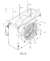
- FIG. 8 is a perspective view of a fan assembly 230 having the fan 32 of the motor drive 12.
- the fan assembly 230 may be separate from other internal components of the motor drive 12, as shown, or the fan 32 may be incorporated directly into a wall of a housing that surrounds the motor drive circuitry.
- the fan assembly 230 includes a fan housing 232 that encloses the fan 32, an impeller 234 of the fan 32 disposed in the fan housing 232, a fan motor (not shown), an air inlet 236, and a cable assembly 238.
- the fan motor turns the impeller 234 at a desired fan speed based on signals from the control circuitry 14.
- the fan 32 draws air in through the air inlet 236, as shown by arrows 240.
- the impeller 234 is designed so that the fan 32 pushes the air upward through the motor drive 12, as shown by arrows 242.
- Other arrangements of the fan assembly 230 may be possible as well.
- FIG. 9 is an exploded perspective view of the fan assembly 230, showing the temperature sensor 36 disposed near the air inlet 236.
- the temperature sensor 36 is located adjacent a back side of the fan housing 232, so that it is not in a direct path of the airflow through the motor drive 12. It may be desirable to position the temperature sensor 36 away from direct airflow so that the temperature measurement is not affected by changes in fan speed.
- the temperature sensor 36 is located within the cable assembly 238, and the temperature sensor 36 may make use of a cable connector 250 of the cable assembly 238.
- the cable connector 250 routes wires 252 between a fan motor 254 of the fan assembly 230 and circuitry of the motor drive 12. Control and feedback signals (e.g., indicative of fan speed) may flow between the control circuitry 14 and the fan motor 254 via the wires 252.
- one of the wires 252 may route power (e.g., 240 V) to the fan motor 254 from power conversion circuitry of the motor drive 12.
- one of the wires 252 may carry a signal indicative of the ambient temperature from the temperature sensor 36 to the control circuitry 14.
- Each of the wires 252 may be routed through the power/communication cable 38 from the fan assembly 230 to the control circuitry 14, as described above with reference to FIGS. 1 and 2 .
- the temperature sensor 36 may be incorporated into already existing structures of the fan assembly 230 of the motor drive 12.
- the temperature sensor 36 may be enclosed by a cover box 256, which protects the temperature sensor 36 from contamination by dirt and other foreign objects.
- the temperature sensor 36 may be a negative temperature coefficient (NTC) sensor, although other types of temperature sensors could be used in other embodiments.
- NTC negative temperature coefficient
- the temperature sensor 36 may be mounted or fastened to the fan housing 232.
- the fan housing 232 may be sheet metal or some other material with a high thermal conductivity so that the temperature of the fan housing 232 is approximately consistent with the ambient air temperature.
- the mass of the fan housing 232 may act as a dampening filter of the temperature, so that the temperature sensor 36 provides a stable signal to the control circuitry 14.
- the temperature sensor 36 may be positioned in open air to detect the ambient air temperature.
- the temperature sensor 36 may yield a relatively robust and dependable air temperature reading.
- the temperature sensor 36 may be incorporated in different ways with the fan assembly 230.
- the temperature sensor 36 may be mounted inside the fan housing 232. This may be particularly useful if the fan motor 254 and the wires 252 are located within the fan housing 232.
- the temperature sensor 36 may be mounted along an inlet air duct of the motor drive 12, such as a duct located just downstream (e.g., in a direction of the arrows 242 of FIG. 8 ) of the fan 32.
- other arrangements of the temperature sensor 36 located proximate an air inlet of the fan 32 may be utilized to directly sense an ambient temperature of the motor drive 12.
- FIG. 10 is a perspective view of components of the motor drive 12 having the fan assembly 230 of FIGS. 8 and 9 .
- the fan motor 254 may receive control and power from circuitry of the motor drive 12 via the power/control cable 38, and the same power/control cable 38 may provide the feedback temperature signals from the temperature sensor 36 to the control circuitry 14.
- the temperature sensor 36 may be configured to provide the feedback temperature signals to the control circuitry 14 wirelessly. That is, the temperature sensor 36 may be communicatively coupled to a processor of the control circuitry via a wireless connection.
- a power interface circuit board 272 is coupled to the power/control cable 38 (via a wire connection 274).
- the power interface circuit board 272 may provide the power needed to operate the fan 32 and communicate with the fan motor 254 in response to control signals from the control circuitry 14.
- the control circuitry 14, again, may be located in the motor drive 12 or outside of the motor drive 12. In some embodiments, the power interface circuit board 272 may form a part of the control circuitry 14.
- the fan assembly 230 may be located at the bottom of the motor drive 12, drawing air into and up through the motor drive 12 to cool the internal components (e.g., power circuitry 18).
- the relatively low cost temperature sensor 36 may leverage the hardware architecture already present in the motor drive 12 to enable relatively accurate prognostics and advanced drive control. This advanced control may allow the motor drive 12 to inform the customer of drive reliability and life during operation of the motor drive 12, increase an amount of product uptime, and ultimately extend the life of the motor drive 12.
Abstract
Description
- The present invention relates generally to the field of power electronic devices, and particularly to implementing diagnostics and prognostics for electric motor drives based on a measured drive inlet temperature.
- A myriad of applications exist in industry for motor drives of various types. In many applications, a motor drive includes a circuit for driving an electromagnetic machine, such as a brushed or brushless motor, stepper motor, or other electromechanical actuator. Such motors and actuators may be internal to or external from their respective motor drives. Multiple motor drives may be positioned across various parts of a factory or manufacturing site. In the case of higher power applications, multi-phase motors are commonly used with separate motor drives that may be positioned in cabinets in the general vicinity of the driven motor.
- Motor drives generally are designed to output only a certain percentage of a maximum power rating for the device. When new, and during most of the useful life of the machines, the power rating may remain as initially assigned, although some derating may be in order due to environmental conditions, machine age, and other factors. That is, the motor drive is derated from a maximum current output to meet a derating requirement specific to the motor drive, effectively lowering the output of the drive and motor. This derating requirement may be different when the motor drive is operated at different ambient temperatures, which may adversely impact both the performance of the machines, as well as shorten their useful life. In addition, a number of prognostics may be determined for the motor drive based on the ambient temperature at which the motor drive operates.
- To perform calculations of various diagnostics, prognostics, and so forth, motor drives often include temperature sensors located on a circuit board of the motor drive. Such temperature sensors are usually buried inside the motor drive itself, enclosed by a protective housing and surrounded by elements that may affect the temperature measurement. In some motor drives, a processor estimates the ambient temperature measurement from the internal operating temperature of the motor drive by applying an energy balance equation. This estimate may be very accurate upon initial operation of the motor drive. Unfortunately, over time this estimate may become less accurate because of operational inefficiencies and degradation of internal cooling mechanisms of the motor drive. Accordingly, it is now recognized that it is desirable to have a motor drive with improved ambient temperature sensing, in order to provide more accurate motor drive diagnostic and prognostic information to a user.
- In a first embodiment, an electric motor drive system includes a fan configured to cool power electronic components of the electric motor drive system. The electric motor drive system also includes a temperature sensor disposed proximate an air inlet of the fan and configured to sense an ambient temperature of air entering the air inlet. In addition, the electric motor drive system includes a processor communicatively coupled to the temperature sensor and configured to determine at least one of a drive prognostic and a drive diagnostic based on the sensed ambient temperature.
- In another embodiment, an electric motor drive system includes a first fan configured to cool power electronic components of a first motor drive and a second fan configured to cool power electronic components of a second motor drive. The electric motor drive system also includes a first temperature sensor disposed proximate a first air inlet of the first fan and configured to sense a first ambient temperature of air entering the first air inlet. In addition, the electric motor drive system includes a second temperature sensor disposed proximate a second air inlet of the second fan and configured to sense a second ambient temperature of air entering the second air inlet. Still further, the electric motor drive system includes a processor communicatively coupled to the first and second temperature sensors and configured to determine at least one of a drive prognostic and a drive diagnostic for each of the first and second motor drives based on the first and second sensed ambient temperatures.
- In a further embodiment, a method includes sensing an ambient air temperature via a temperature sensor disposed proximate an air inlet of a fan of an electric motor drive. The fan is configured to cool power electronic components of the electric motor drive via air drawn through the air inlet. The method also includes determining, via a processor communicatively coupled to the temperature sensor, at least one of a drive prognostic and a drive diagnostic based on the sensed ambient temperature.
- These and other features, aspects, and advantages of the presently disclosed embodiments will become better understood when the following detailed description is read with reference to the accompanying drawings in which like characters represent like parts throughout the drawings, wherein:
-
FIG. 1 is a schematic diagram of a motor drive with an inlet temperature sensor in accordance with an embodiment of the present disclosure; -
FIG. 2 is a schematic diagram of a motor drive system having multiple motor drive power modules to drive a single motor in accordance with an embodiment of the present disclosure; -
FIG. 3 is a schematic diagram of power electronic switching circuitry of the motor drive ofFIG. 1 in accordance with an embodiment of the present disclosure; -
FIG. 4 is a block diagram illustrating various functions performed by control circuitry of a motor drive equipped with an inlet temperature sensor in accordance with an embodiment of the present disclosure; -
FIG. 5 is a process flow diagram illustrating a method for determining thermal system defects in accordance with an embodiment of the present disclosure; -
FIG. 6 is a process flow diagram illustrating a method for determining power module life in accordance with an embodiment of the present disclosure; -
FIG. 7 is a process flow diagram illustrating a method for determining fan life in accordance with an embodiment of the present disclosure; -
FIG. 8 is a perspective view of a fan assembly of the motor drive ofFIG. 1 in accordance with an embodiment of the present disclosure; -
FIG. 9 is an exploded perspective view of the fan assembly ofFIG. 8 in accordance with an embodiment of the present disclosure; -
FIG. 10 is a perspective view of certain components of a motor drive having the fan assembly ofFIGS. 8 and9 in accordance with an embodiment of the present disclosure; and -
FIG. 11 is a perspective view of the motor drive having the fan assembly ofFIGS. 8 and9 in accordance with an embodiment of the present disclosure. - Presently disclosed embodiments are directed to systems and methods for determining prognostics and diagnostics for electric motor drive systems. Specifically, the systems and methods described herein use an ambient air temperature measurement to determine the drive prognostics and diagnostics. The ambient air temperature may be measured directly using a temperature sensor positioned near an air inlet of the motor drive. This inlet air temperature measurement may be more accurate than an ambient temperature estimate that is calculated from an internal temperature of the power module of the motor drive. Thus, the systems and methods disclosed herein may provide more accurate prognostics and diagnostics for the motor drive during operation of the motor drive. By implementing certain actions based on the determined prognostics and diagnostics, the motor drive systems may receive improved preventive maintenance and drive control, which may ultimately lead to more efficient drive operation and extended life of the motor drive. The techniques discussed below may be applied to any desirable electric motor drive system, including a system with multiple motor drives operating in parallel to drive a single process.
- Turning now to the drawings,
FIG. 1 is a block diagram of amotor drive system 10 illustrating various internal components of amotor drive 12. For example, themotor drive 12 may includecontrol circuitry 14,driver circuitry 16, andpower circuitry 18. Thepower circuitry 18 may receive three-phase power 20 and output threephase power 22 to amotor 24. Thepower circuitry 18 may include, for example, power electronic switching circuitry. Thecontrol circuitry 14 anddriver circuitry 16 may include a control circuit board and various optional function circuits. Thedriver circuitry 16 may signal switches of thepower circuitry 18 to rapidly close and open, resulting in a three phase waveform output acrossoutput terminals driver circuitry 16 is controlled by thecontrol circuitry 14, which may operate autonomously, or which may respond to command inputs from a remote control monitor through a network. Similarly, operation of thedriver circuitry 16 may be coordinated, via thecontrol circuitry 14, with that of other drives. Many different control schemes and functions may be implemented by a processor of thecontrol circuitry 14, and programs for such operation may be stored on the control board, such as for closed loop speed control, closed loop torque control, drive derating control, among many others. - The
motor drive 12 may include afan 32 to provide cooling to the circuitry (e.g., power circuitry 18) internal to themotor drive 12. Thefan 32 may be configured to draw relatively cool ambient air into themotor drive 12, as shown byarrows 34, and to direct the air through a duct or wind tunnel that houses the various circuitry. As discussed in detail below, present embodiments may include atemperature sensor 36 disposed proximate an air inlet of thefan 32 and used to sense the temperature of the ambient air entering the air inlet. Thetemperature sensor 36 may provide ambient temperature feedback signals to thecontrol circuitry 14, for example via a fan power/control cable 38 of themotor drive 12, or wirelessly. Thecontrol circuitry 14 may perform various calculations in substantially real time to determine diagnostics (e.g., drive derating requirements) and prognostics of themotor drive 12 based on the sensed inlet temperature. Such calculations may provide more accurate predictive prognostics to a user than would be available without theinlet temperature sensor 36. In addition, thecontrol circuitry 14 may provide enhanced control of themotor drive 12 based on these calculations to increase the expected lifetime and operating efficiency of themotor drive 12. - The
temperature sensor 36 may be located proximate a fan inlet in various other arrangements of themotor drive system 10. For example, inlet temperature sensing may be applied to amotor drive system 10 that uses multiple separate motor drives 12 to drive a single process.FIG. 2 is one such embodiment, having two or more motor drives or drivemodules 12 operably coupled in parallel to drive themotor 24. In the illustrated embodiment, each of the motor drives 12 is equipped with thedriver circuitry 16 and thepower circuitry 18. However, thecontrol circuitry 14 used to control thedriver circuitry 16 for each of the motor drives 12 may be located remotely from the motor drives 12. Any number of motor drives 12 may be added to or removed from themotor drive system 10 to condition a desired amount of power output to themotor 24. - In such embodiments, each of the motor drives 12 may be equipped with the
temperature sensor 36 disposed near an air inlet of thefan 32. For example, in the illustrated embodiment a first motor drive 50 includes a first fan 52 with a first temperature sensor 54. Similarly, a second motor drive 56 includes a second fan 58 with a second temperature sensor 60. Each of the temperature sensors 54 and 60 may be communicatively coupled to thecontrol circuitry 14 via respective cables 62 and 64. In such embodiments, thecontrol circuitry 14 may be configured to determine prognostics for each of the motor drives 50 and 56 based on the respective inlet air temperature measurements. - Calculations performed via the
control circuitry 14 may be utilized to identify one or more of the motor drives 12 that are experiencing operational difficulties. For example, if internal defects or contaminants are reducing the amount of cooling taking place in themotor drive 12, the change in temperature between ambient temperature and internal temperature of one drive may be significantly less than the change in temperature of another drive connected in parallel. In response, thecontrol circuitry 14 may output signals to provide a notification to a user that aparticular motor drive 12 is not operating effectively. In other embodiments, two or more motor drives 12 may be coupled in parallel, as shown, each having itsown control circuitry 14 with a processor for determining and/or implementing drive diagnostics or prognostics. In such cases, thecontrol circuitry 14 of each of the motor drives 12 may be linked together via another control structure to control operation of themotor 24. -
FIG. 3 is a schematic diagram that details components of thepower circuitry 18. In the illustrated embodiment, thepower circuitry 18 includes power electronic switching circuitry. Thepower circuitry 18 may be located within a power conversion module of themotor drive 12. As mentioned above, thepower circuitry 18 typically receives the threephase power 20 as an input, such as from the power grid. The three phase power source is electrically coupled to a set ofinput terminals rectifier circuitry 76. Therectifier circuitry 76 includes components, such asdiodes 78 that perform full wave rectification of the three phase voltage waveform. After rectification, all phases of the incoming power are combined to provide DC power to alow side 80 and to thehigh side 82 of a DC bus.Inductors 84 may be coupled to both the high and low sides of the DC bus and act as chokes for smoothing the rectified DC voltage waveform. One ormore filter capacitors 86 may link thehigh side 82 and thelow side 80 of the DC bus and are also configured to smooth the rectified DC voltage waveform. Together, theinductors 84 and thecapacitors 86 serve to remove most of the ripple from the waveform, so that the DC bus carries a waveform closely approximating a true DC voltage. It should be noted that the three-phase implementation described herein is not intended to be limiting, and the invention may be employed on single-phase circuitry, as well as on circuitry designed for applications other than motor drives. - An
inverter 88 is coupled to the DC bus and generates a three phase output waveform at a desired frequency for driving themotor 24 connected to theoutput terminals inverter 88, two insulated gate bipolar transistors (IGBT's) 90 are coupled in series for each phase. The pair oftransistors 90 may be coupled from collector to emitter, between thehigh side 82 andlow side 80 of the DC bus. Three of these transistor pairs are then coupled in parallel to the DC bus, for a total of sixtransistors 90. Each of theoutput terminals transistors 90. Thedriver circuitry 16 signals thetransistors 90 to rapidly close and open, resulting in a three phase waveform output acrossoutput terminals driver circuitry 16 is controlled by thecontrol circuitry 14, based on various inputs. Such inputs may include, for example, operator inputs received from an operator interface. In addition, thecontrol circuitry 14 may receivefeedback 91 representative of a current operational state of themotor drive 12.Such feedback 91 may include sensor feedback from one or more sensors (e.g., temperature sensor 36) disposed throughout themotor drive system 10. - In some embodiments, the
motor drive 12 may be a regenerative motor drive configured to operate in a regenerative phase of operation at times and in the driving operation described above at other times. In the regenerative phase of operation, therectifier circuitry 76 may allow for inertial energy or braking energy of the three-phase motor 24 to be redirected back into the supply mains (e.g., power grid) of the threephase power 20. As will be appreciated by those skilled in the art, during regenerative operation, themotor 24 behaves as a three-phase generator. Consequently, switches in therectifier circuitry 76 may be switched by thedriver circuitry 16 in such a way as to allow the alternating current flowing through the DC bus to pass back into the supply network, thereby recapturing inertial energy of themotor 24. - As noted above, the
motor drive 12 may be equipped with thefan 32 for cooling, thepower circuitry 18 throughout drive operation. As illustrated, thefan 32 may be positioned in themotor drive 12 such that air drawn through an air inlet of the fan 32 (e.g., arrows 34) is directed over thepower circuitry 18 of themotor drive 12. The air may provide cooling to the power electronic switching components, which may otherwise overheat due to the rapid opening and closing of thetransistors 90.Arrows 92 represent the air flowing over each of therectifier circuitry 76, thehigh side 82 andlow side 80 of the DC bus, and theinverter 88. Thepower circuitry 18 may all reside on a single circuit board that is disposed in a housing of themotor drive 12, and the fan may direct the cooling air over the circuit board. In some embodiments, the air may flow over thedriver circuitry 16 and/or thecontrol circuitry 14 as well, depending on whether these components are located in themotor drive 12 and depending on the spatial arrangement of the components relative to thefan 32. - As noted above, the
temperature sensor 36 located near an air inlet of thefan 32 may provide inlet temperature feedback for control of themotor drive 12 and for determining relatively accurate prognostics and diagnostics of themotor drive 12.FIGS. 1-3 represent embodiments ofmotor drive systems 10 that may utilize an inlet temperature measurement to determine reliability calculations, remaining life estimations, drive health evaluation, component health evaluation (e.g., the fan 32), derating requirements, and other information for promoting efficient operation of one or more motor drives 12. These embodiments are meant to be illustrative and not limiting, so that atemperature sensor 36 may be disposed near thefan 32 of any other type ofmotor drive system 10 as well. - Having now described several types of
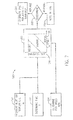
motor drive systems 10 that may utilize the disclosed inlet temperature sensor, a more detailed description of the uses of the sensed temperature will be provided. To that end,FIG. 4 is a block diagram providing several functions that may be performed by a processor of themotor drive 12, the processor being communicatively coupled to thetemperature sensor 36 in accordance with the disclosed techniques. The processor may include any desirable processing system used to carry out the calculations described herein. For example, the processor may include a microprocessor located in thecontrol circuitry 14 of themotor drive system 10. Thecontrol circuitry 14 may provide control signals to thedriver circuitry 16 for executing various actions determined based on the processor's calculations. -
Inputs 110 to the processor may include, among other things, anair temperature measurement 112 and any number of various drive counters 114. Theair temperature measurement 112 may include a signal indicative of air temperature sent from thetemperature sensor 36 to the processor at different times throughout operation of themotor drive 12. In some embodiments, thetemperature sensor 36 may provide such signals to the processor at a predetermined interval, especially when thetemperature measurement 112 is used asfeedback 91 for control functions of thecontrol circuitry 14. In other embodiments, thetemperature sensor 36 may provide theair temperature measurement 112 to the processor at desired times based upon receipt of a signal from the processor. This may be the case when thetemperature measurement 112 is used for determining prognostics and providing the prognostics to an operator upon request. - In addition to the
temperature measurement 112, the processor may receive signal inputs corresponding to the drive counters 114 present in themotor drive 12. These drive counters 114 may include any additional parameter that is determined or counted at a regular interval to providefeedback 91 for controlling themotor drive 12. For example, the drive counters 114 may include a fan run time, a fan speed, and a module temperature. The fan run time represents how long thefan 32 has been operating, and the fan speed represents the substantially instantaneous speed of thefan 32. The module temperature may represent a temperature of one or more components internal to themotor drive 12, as determined via embedded temperature sensors. For example, one or more temperature sensors may continuously monitor temperatures of thetransistors 90 in thepower circuitry 18. This may allow the processor to determine a change in temperature between the ambient air (e.g., sensed via temperature sensor 36) and the power circuitry 18 (e.g., sensed via embedded temperature sensors). Other drive counters 114 may be provided asinputs 110 to the processor as well. - The processor may utilize the
inputs 110 to perform any number of desiredcalculations 118.Such calculations 118 may be performed at any point of time during operation of themotor drive 12, so that they are substantially near real-time calculations. Based on thecalculations 118, the processor may determine at least one of a drive prognostic or a drive diagnostic during operation of themotor drive 12. Thecalculations 118 may be performed as code executed via the processor, the code being stored in a memory or other non-transitory computer-readable medium coupled to the processor. The processor may calculate several different parameters or diagnostics related to drive operation, and some non-limiting examples are provided in the illustrated embodiment. These calculated parameters may include, for example, afan life 120, adrive derating requirement 122, adrive reliability 124, apower module life 126, and arun time 128. - The
fan life 120 may be an expected lifetime or remaining lifetime of thefan 32, as determined based on fan speed, fan run time, and theair temperature measurement 112. Thedrive derating requirement 122 may be calculated based on theair temperature measurement 112, since the derating requirement for aparticular motor drive 12 is generally related to the ambient temperature at which themotor drive 12 is operated. Specifically, when themotor drive 12 runs at a higher ambient temperature, the maximum allowed power output of themotor drive 12 should be lower so that internal drive components (e.g., power circuitry 18) do not overheat. Similarly, themotor drive 12 may operate at higher amperages when run in an environment with a relatively lower ambient temperature. By adjusting (e.g., uprating or derating) the amperage of themotor drive 12 according to the ambient temperature, it may be possible to improve an overall lifetime of themotor drive 12. - The
drive reliability 124 may be a measure of the ability of themotor drive 12 to perform its designated function (e.g., output power at a desired rating) for a certain period of time. Thisdrive reliability 124 may be expressed in terms of a probability of themotor drive 12 failing, and may be determined based at least in part on theair temperature measurement 112. Thepower module life 126 may be an expected lifetime or remaining lifetime of the power conversion module (e.g., power circuitry 18) of themotor drive 12, as determined based on a change in temperature across the power module components. Therun time 128 may be an amount of time themotor drive 12 has been operating, as determined by adrive counter 114 in thecontrol circuitry 14, thedriver circuitry 16, or thepower circuitry 18. Therun time 128 may be useful for determining prognostics related to the efficiency or the remaining lifetime of themotor drive 12. - Some of the
calculations 118 performed by the processor may be used to provide relativelyaccurate prognostics 130 for themotor drive 12, while others may be used to generate control signals for performingvarious actions 132 via thecontrol circuitry 14. Theprognostics 130 may include any predictive information related to drive performance, including thefan life 120, thedrive reliability 124, thepower module life 126, acapacitor life 134, andthermal system defects 136. Thecapacitor life 134 may be an expected total lifetime or remaining lifetime of the one ormore capacitors 86 in thepower circuitry 18, and may be determined based on theair temperature measurement 112. The processor may signal an operator interface to indicate thecapacitor life 134 to the user or to provide a warning when thecapacitor 86 is almost in need of replacement. Thethermal system defects 136 may be determined based on an efficiency of a cooling system of themotor drive 12, or how much heat the cooling system removes from internal components of themotor drive 12 at a certain inlet air temperature. Based in part on theair temperature measurement 112, the processor may determine whether defects or degradation are present within the cooling system. Such defects may include, for example, dust accumulation on a heat sink of thepower circuitry 18, air not flowing through themotor drive 12 at a high enough flow rate, improper installation of thermal system components, a clogged filter, and so forth. An operator may perform maintenance on themotor drive 12 when such thermal defects are identified by themotor drive system 10 to increase an operating efficiency of themotor drive 12. - The processor may be configured to determine any number of the above-listed
prognostics 130, among others, related to operation of themotor drive 12. Again, theprognostics 130 may depend on the temperature of the environment in which themotor drive 12 is operated. Thus, an accurate measurement of the ambient temperature may be desirable for accurately determining theprognostics 130. A relatively more accurate measurement of the ambient temperature may be obtained via thetemperature sensor 36 placed at the fan inlet, as opposed to sensors embedded within the motor drive circuitry. - In addition to providing
prognostics 130 throughout operation of themotor drive 12, the processor may provide outputs to components (e.g., control circuitry 14) of themotor drive 12 for performingvarious actions 132. Theseactions 132 may include controlling operations of themotor drive 12 or providing information (e.g.,prognostics 130 or warnings) to an operator. - In the illustrated embodiment, the
actions 132 include adjusting (block 138) a drive amp rating so that themotor drive 12 operates within the calculateddrive derating requirement 122. This adjustment may involve derating the amperage output of themotor drive 12 when theair temperature measurement 112 is relatively high. Similarly, when theair temperature measurement 112 is relatively low the rating adjustment may involve uprating the amperage output of themotor drive 12. This may ensure that thepower circuitry 18 operates relatively efficiently (e.g., higher estimated power module life 126) while still operating within thederating requirement 122. That is, a processor of thecontrol circuitry 14 adjusts a performance of themotor drive 12 based on the determineddrive derating requirement 122. - Adjusting (block 140) a fan speed of the
fan 32 is anotheraction 132 that may be performed based on thecalculations 118 and/or theprognostics 130 determined by the processor. In some embodiments, the fan speed may be reduced when theair temperature measurement 112 is lower, in order to extend thefan life 120 and/or thepower module life 126. In other embodiments, the fan speed may be reduced to maintain a desired overall efficiency of themotor drive 12. As noted previously, the processor may provide outputs to an operator interface for warning a user of potential inefficiencies or a request for maintenance. As an example, theactions 132 prompted by the processor may include providing a clogged thermal system warning 142 based on the identifiedthermal system defects 136 within themotor drive 12. -
FIGS. 5-7 detail some examples of thecalculations 118,determined prognostics 130, andactions 132 performed by thecontrol circuitry 14 as outlined inFIG. 4 . Specifically,FIG. 5 is a process flow diagram of amethod 150 for determining thethermal system defects 136 and performingcertain actions 132 based on the determination. Themethod 150 includes measuring (block 152) the inlet air temperature Tin . This is theair temperature measurement 112 determined by thetemperature sensor 36 near the air inlet. In addition, themethod 150 includes measuring (block 154) an IGBT negative temperature coefficient (NTC) temperature TNTC . This is a temperature of one or more of thetransistors 90 in thepower circuitry 18 of themotor drive 12, and may be measured using a temperature sensor embedded in thepower circuitry 18. The temperature sensor may be a NTC sensor or any other desirable sensor. Using these monitored temperatures as inputs, thecontrol circuitry 14 may calculate (block 156) a temperature rise Trise . This value may represent a change in temperature of the air between the inlet of thefan 32 and thepower circuitry 18, calculated according to the following expression:
- In addition to determining Trise , the
method 150 may include calculating (block 158) IGBT losses PIGBT. These calculated losses represent power lost across thepower circuitry 18 through heat generated by the rapidly switchingtransistors 90. The calculation to determine the losses may be based on the controlled operation (e.g., switching speed) of thepower circuitry 18. Thecontrol circuitry 14 may determine this operation, and the expected losses associated therewith. In addition, thecontrol circuitry 14 may determine whetherthermal system defects 136 exist based on arelationship 160 between thecalculated T rise 162 and thecalculated P IGBT 164. Therelationship 160 betweenT rise 162 andP IGBT 164 may indicate that themotor drive 12 has particular thermal system defects 136 (e.g., clogged or missing) or that themotor drive 12 is operating as desired (e.g., normal). - The
control circuitry 14 may perform anassessment 166 based on therelationship 160 to determine a current operational state of the thermal system of themotor drive 12. Thecontrol circuitry 14 may determine, for example, that a thermal system component of themotor drive 12 is clogged. The "clogged" determination may be made when the Trise is higher than expected for the PIGBT of thepower circuitry 18. This may indicate that the cooling air and/or heat sink of themotor drive 12 are not providing the expected cooling to the internal components of themotor drive 12, and thus may be clogged. In response to this determination, thecontrol circuitry 14 may generate (block 168) a clogged air flow alarm. This alarm may correspond to the clogged thermal system warning 142 ofFIG. 4 . This alarm may indicate to an operator that an air filter or heat sink of themotor drive 12 is clogged, thefan 32 is degraded, or the air flow through themotor drive 12 is otherwise obstructed. - The
control circuitry 14 may determine via theassessment 166 that a thermal system component of themotor drive 12 is missing. The "missing" determination may be made when the Trise is lower than expected for the PIGBT of thepower circuitry 18. This may indicate that cooling air is flowing through themotor drive 12 at a higher flow rate than necessary to cool thepower circuitry 18. In response to this determination, thecontrol circuitry 14 may generate (block 170) a missing filter alarm to indicate to an operator that an air filter is missing from themotor drive 12, or that a wrong type offan 32 is in use. -
FIG. 6 is a process flow diagram of amethod 176 for determining thepower module life 126 of themotor drive 12 based in part on theair temperature measurement 112. Similar to themethod 150 ofFIG. 5 , thismethod 176 may compare the calculated Trise and the calculated PIGBT. In themethod 176, adifferent relationship 178 between the Trise and the PIGBT may be used to determine whether thetransistors 90 are operating normally, nearing the point of needing replacement, or in need replacement. Thisrelationship 178 may be related to thepower module life 126 discussed with reference toFIG. 4 . - The
control circuitry 14 may perform anassessment 180 based on therelationship 178 to determine a current operational state of thepower circuitry 18. For example, thecontrol circuitry 14 may determine that one or more of thetransistors 90 need to be replaced when, according to therelationship 178, the PIGBT is lower than expected for the heat output by the power circuitry 18 (e.g., based on Trise ). In response to this determination, thecontrol circuitry 14 may provide signals to generate (block 182) an IGBT replacement warning. This warning may include, for example, a visualization or text string on a display, or an alarm, of an operator interface in communication with thecontrol circuitry 14. The text may read, for example, "IGBTs are nearing the end of their useful life. Replace soon." Based on signals received from thecontrol circuitry 14, the operator interface may indicate to an operator that the power module (e.g., circuit board) that holds the IGBTs should be replaced. If theassessment 180 indicates that one or more of the IGBTs are nearing the end of their life ("warning"), the warning may be noted (block 184) in a log that is integral with or separate from thecontrol circuitry 14. Thecontrol circuitry 14 may access the log, utilizing this and other information stored in the log to improve thedetermined prognostics 130. -
FIG. 7 is a process flow diagram of amethod 190 for determining thefan life 120 of thefan 32 based in part on theair temperature measurement 112, and implementing various actions in response to thedetermined fan life 120. As with the previously describedmethods method 190 includes measuring (block 152) Tin . In addition, themethod 190 includes determining (block 192) a run time t of themotor drive 12, for example using aspecific drive counter 114 of themotor drive 12. Themethod 190 also includes determining (block 194) a fan speed (e.g., in RPMs) of thefan 32 using another of the drive counters 114 in themotor drive 12. Theair temperature measurement 112, the run time, and the fan speed all may be provided asinputs 196 to determine a remainingfan life 198 based on aspecific relationship 200 of theinputs 196. That is, the remainingfan life 198 is a function of each of theinputs 196. - The
control circuitry 14 may perform anassessment 202 of the remainingfan life 198 at regular intervals and implement certain actions in response to theassessment 202. For example, thecontrol circuitry 14 may determine that thefan 32 should be replaced. This may be the case when the fan speed decreases significantly, compared to what the fan speed should be when themotor drive 12 is operating at a certain ambient temperature, and the run time of themotor 12 continues to increase as the power electronics are operating. When this determination is made, thecontrol circuitry 14 may generate (block 204) a fan replacement warning, which may be a visualization, or a visible or audible message to an operator. For example, the warning message may include "Fan is nearing the end of useful life. Replace soon." In response to theassessment 202 yielding a relatively low remainingfan life 198, thecontrol circuitry 14 may note (block 206) a warning in a log. As noted above, thecontrol circuitry 14 may control operation of multiple motor drives 12 operating in parallel. The fan replacement warning may be specific to thefan 32 of aparticular motor drive 12, so that the operator knows whichmotor drive 12 has afan 32 that needs replacing. Similarly, thecontrol circuitry 14 may perform the warnings or actions in response to theother assessments - Having now described several examples of calculations, prognostics, and actions that may be performed based on an ambient air temperature,
FIGS. 8-11 provide a more detailed description of the physical arrangement of thetemperature sensor 36 that senses this temperature. Specifically,FIG. 8 is a perspective view of afan assembly 230 having thefan 32 of themotor drive 12. Thefan assembly 230 may be separate from other internal components of themotor drive 12, as shown, or thefan 32 may be incorporated directly into a wall of a housing that surrounds the motor drive circuitry. In the illustrated embodiment, thefan assembly 230 includes afan housing 232 that encloses thefan 32, animpeller 234 of thefan 32 disposed in thefan housing 232, a fan motor (not shown), anair inlet 236, and acable assembly 238. The fan motor turns theimpeller 234 at a desired fan speed based on signals from thecontrol circuitry 14. Thefan 32 draws air in through theair inlet 236, as shown byarrows 240. In the illustrated embodiment, theimpeller 234 is designed so that thefan 32 pushes the air upward through themotor drive 12, as shown byarrows 242. Other arrangements of thefan assembly 230 may be possible as well. -
FIG. 9 is an exploded perspective view of thefan assembly 230, showing thetemperature sensor 36 disposed near theair inlet 236. In the illustrated arrangement, thetemperature sensor 36 is located adjacent a back side of thefan housing 232, so that it is not in a direct path of the airflow through themotor drive 12. It may be desirable to position thetemperature sensor 36 away from direct airflow so that the temperature measurement is not affected by changes in fan speed. - In the illustrated embodiment, the
temperature sensor 36 is located within thecable assembly 238, and thetemperature sensor 36 may make use of acable connector 250 of thecable assembly 238. Thecable connector 250routes wires 252 between afan motor 254 of thefan assembly 230 and circuitry of themotor drive 12. Control and feedback signals (e.g., indicative of fan speed) may flow between thecontrol circuitry 14 and thefan motor 254 via thewires 252. In addition, one of thewires 252 may route power (e.g., 240 V) to thefan motor 254 from power conversion circuitry of themotor drive 12. Along with the communication and power routed to thefan motor 254, one of thewires 252 may carry a signal indicative of the ambient temperature from thetemperature sensor 36 to thecontrol circuitry 14. Each of thewires 252 may be routed through the power/communication cable 38 from thefan assembly 230 to thecontrol circuitry 14, as described above with reference toFIGS. 1 and2 . In this way, thetemperature sensor 36 may be incorporated into already existing structures of thefan assembly 230 of themotor drive 12. - The
temperature sensor 36, along with thewires 252, may be enclosed by acover box 256, which protects thetemperature sensor 36 from contamination by dirt and other foreign objects. In an embodiment, thetemperature sensor 36 may be a negative temperature coefficient (NTC) sensor, although other types of temperature sensors could be used in other embodiments. As illustrated, thetemperature sensor 36 may be mounted or fastened to thefan housing 232. Thefan housing 232 may be sheet metal or some other material with a high thermal conductivity so that the temperature of thefan housing 232 is approximately consistent with the ambient air temperature. The mass of thefan housing 232 may act as a dampening filter of the temperature, so that thetemperature sensor 36 provides a stable signal to thecontrol circuitry 14. In other embodiments, however, thetemperature sensor 36 may be positioned in open air to detect the ambient air temperature. - The illustrated location of the
temperature sensor 36 may yield a relatively robust and dependable air temperature reading. In other embodiments, thetemperature sensor 36 may be incorporated in different ways with thefan assembly 230. For example, thetemperature sensor 36 may be mounted inside thefan housing 232. This may be particularly useful if thefan motor 254 and thewires 252 are located within thefan housing 232. Still further, thetemperature sensor 36 may be mounted along an inlet air duct of themotor drive 12, such as a duct located just downstream (e.g., in a direction of thearrows 242 ofFIG. 8 ) of thefan 32. Again, other arrangements of thetemperature sensor 36 located proximate an air inlet of thefan 32 may be utilized to directly sense an ambient temperature of themotor drive 12. -
FIG. 10 is a perspective view of components of themotor drive 12 having thefan assembly 230 ofFIGS. 8 and9 . As noted above, thefan motor 254 may receive control and power from circuitry of themotor drive 12 via the power/control cable 38, and the same power/control cable 38 may provide the feedback temperature signals from thetemperature sensor 36 to thecontrol circuitry 14. In other embodiments, thetemperature sensor 36 may be configured to provide the feedback temperature signals to thecontrol circuitry 14 wirelessly. That is, thetemperature sensor 36 may be communicatively coupled to a processor of the control circuitry via a wireless connection. In the illustrated embodiment, a powerinterface circuit board 272 is coupled to the power/control cable 38 (via a wire connection 274). The powerinterface circuit board 272 may provide the power needed to operate thefan 32 and communicate with thefan motor 254 in response to control signals from thecontrol circuitry 14. Thecontrol circuitry 14, again, may be located in themotor drive 12 or outside of themotor drive 12. In some embodiments, the powerinterface circuit board 272 may form a part of thecontrol circuitry 14. - As shown in
FIG. 11 , all (or nearly all) of the components of themotor drive 12 may be enclosed in adrive housing 276. Thefan assembly 230 may be located at the bottom of themotor drive 12, drawing air into and up through themotor drive 12 to cool the internal components (e.g., power circuitry 18). By sensing the temperature near the air inlet of thefan 32, it may be possible to determine a more accurate ambient temperature of themotor drive 12 than would be possible by estimating the ambient temperature from feedback of sensors embedded in the circuitry of themotor drive 12. The relatively lowcost temperature sensor 36 may leverage the hardware architecture already present in themotor drive 12 to enable relatively accurate prognostics and advanced drive control. This advanced control may allow themotor drive 12 to inform the customer of drive reliability and life during operation of themotor drive 12, increase an amount of product uptime, and ultimately extend the life of themotor drive 12. - While only certain features of the invention have been illustrated and described herein, many modifications and changes will occur to those skilled in the art. It is, therefore, to be understood that the appended claims are intended to cover all such modifications and changes as fall within the true spirit of the invention.
- The following is a list of further preferred embodiments of the invention:
-
Embodiment 1. An electric motor drive system, comprising:- a fan configured to cool power electronic components of the electric motor drive system;
- a temperature sensor disposed proximate an air inlet of the fan and configured to sense an ambient temperature of air entering the air inlet; and
- a processor communicatively coupled to the temperature sensor and configured to determine at least one of a drive prognostic and a drive diagnostic based on the sensed ambient temperature.
- Embodiment 2. The electric motor drive system of
embodiment 1, wherein the processor is configured to determine at least one of the drive prognostic or the drive diagnostic during operation of the electric motor drive system. - Embodiment 3. The electric motor drive system of
embodiment 1, wherein at least one of the drive prognostic or the drive diagnostic comprises an expected lifetime of the fan. - Embodiment 4. The electric motor drive system of
embodiment 1, wherein at least one of the drive prognostic or the drive diagnostic comprises a reliability of the electric motor drive system - Embodiment 5. The electric motor drive system of
embodiment 1, wherein at least one of the drive prognostic or the drive diagnostic comprises an expected lifetime of a power conversion module. - Embodiment 6. The electric motor drive system of
embodiment 1, wherein at least one of the drive prognostic or the drive diagnostic comprises an expected lifetime of a capacitor of the electric motor drive system. - Embodiment 7. The electric motor drive system of
embodiment 1, wherein at least one of the drive prognostic or the drive diagnostic comprises a thermal system defect of the electric motor drive system. - Embodiment 8. The electric motor drive system of
embodiment 1, wherein the drive diagnostic comprises a derating requirement of the electric motor drive system. - Embodiment 9. The electric motor drive system of embodiment 8, wherein the processor is configured to output a control signal to adjust a performance of the electric motor drive system based on the determined derating requirement.
-
Embodiment 10. The electric motor drive system ofembodiment 1, wherein the processor is configured to output a control signal to adjust a speed of the fan based on the determined prognostic. - Embodiment 11. The electric motor drive system of
embodiment 1, wherein the processor is configured to output a control signal to provide a warning indication to an operator based on the determined prognostic. -
Embodiment 12. The electric motor drive system ofembodiment 1, wherein the temperature sensor is disposed in an inlet air duct of the electric motor drive system. - Embodiment 13. The electric motor drive system of
embodiment 1, wherein the temperature sensor is disposed adjacent a fan housing of the electric motor drive system. -
Embodiment 14. The drive system ofembodiment 1, comprising control circuitry communicatively coupled to the temperature sensor via a cable configured to route power and/or control signals between the control circuitry and the fan. - Embodiment 15. The drive system of
embodiment 1, comprising control circuitry communicatively coupled to the temperature sensor via a wireless connection. -
Embodiment 16. The electric motor drive system ofembodiment 1, wherein the processor is communicatively coupled to two or more temperature sensors disposed proximate air inlets of two or more respective motor drives, and wherein the processor is configured to determine at least one of a drive prognostic or a drive diagnostic for each of the motor drives. - Embodiment 17. An electric motor drive system, comprising:
- a first fan configured to cool power electronic components of a first motor drive;
- a first temperature sensor disposed proximate a first air inlet of the first fan and configured to sense a first ambient temperature of air entering the first air inlet;
- a second fan configured to cool power electronic components of a second motor drive;
- a second temperature sensor disposed proximate a second air inlet of the second fan and configured to sense a second ambient temperature of air entering the second air inlet; and
- one or more processors communicatively coupled to the first and second temperature sensors and configured to determine at least one of a drive prognostic and a drive diagnostic for each of the first and second motor drives based on the first and second sensed ambient temperatures.
-
Embodiment 18. The electric motor drive system of embodiment 17, comprising a single processor configured to determine the at least one of the drive prognostic or the drive diagnostic during operation of the first and second motor drives in parallel to drive a single process. - Embodiment 19. The electric motor drive system of embodiment 17, comprising a first processor configured to determine the at least one of the drive prognostic or the drive diagnostic for the first motor drive and a second processor configured to determine the at least one of the drive prognostic or the drive diagnostic for the second motor drive, during operation of the first and second motor drives in parallel to drive a single process.
-
Embodiment 20. A method, comprising:- sensing an ambient air temperature via a temperature sensor disposed proximate an air inlet of a fan of an electric motor drive, wherein the fan is configured to cool power electronic components of the electric motor drive via air drawn through the air inlet; and
- determining, via a processor communicatively coupled to the temperature sensor, at least one of a drive prognostic and a drive diagnostic based on the sensed ambient temperature.
- Embodiment 21. The method of
embodiment 20, comprising adjusting a performance of the drive device based on the determined drive diagnostic. -
Embodiment 22. The method ofembodiment 20, comprising generating an alarm based on the determined drive prognostic. - Embodiment 23. The method of
embodiment 20, comprising sensing a power module temperature via a temperature sensor disposed proximate the power electronic components, calculating a temperature difference between the sensed ambient air temperature and the sensed power module temperature, and determining the drive prognostic based on the calculated temperature difference. -
- 10
- motor drive system
- 12
- motor drive
- 14
- control circuitry
- 16
- driver circuitry
- 18
- power circuitry
- 20
- receive three phase power
- 22
- output three phase power
- 24
- motor
- 26
- output terminals
- 28
- output terminals
- 30
- output terminals
- 32
- fan
- 34
- arrows
- 36
- temperature sensor
- 38
- power/control cable
- 50
- first motor drive
- 52
- first fan
- 54
- first temperature sensor
- 56
- second motor drive
- 58
- second fan
- 60
- second temperature sensor
- 62
- respective cables
- 64
- respective cables
- 70
- input terminals
- 72
- input terminals
- 74
- input terminals
- 76
- rectifier circuitry
- 78
- diodes
- 80
- low side
- 82
- high side
- 84
- inductors
- 86
- filter capacitors
- 88
- inverter
- 90
- transistors
- 91
- feedback
- 92
- arrows
- 110
- inputs
- 112
- air temperature measurement
- 114
- drive counters
- 118
- calculations
- 120
- fan life
- 122
- drive derating requirement
- 124
- drive reliability
- 126
- power module life
- 128
- run time
- 130
- prognostics (determined by the processor)
- 132
- actions
- 134
- capacitor life
- 136
- thermal system defects
- 138
- block (adjusting a drive amp rating)
- 140
- block (adjusting a fan speed)
- 142
- clogged thermal system warning
- 150
- method (determining thermal system defects)
- 152
- block (measuring Tin )
- 154
- block (measuring an IGBT negative temperature coefficient (NTC) temperature TNTC )
- 156
- block (calculating a temperature rise Trise)
- 158
- block (calculating IGBT losses PIGBT)
- 160
- relationship (between the calculated Trise and the calculated PIGBT)
- 166
- assessment
- 168
- block (generate a clogged air flow alarm)
- 170
- block (generate a missing filter alarm)
- 176
- method (determining power module life)
- 178
- relationship (between the Trise and the PIGBT)
- 180
- assessment
- 182
- block (generate an IGBT replacement warning)
- 184
- block (warning may be noted)
- 190
- method (determining fan life)
- 192
- block (determining run time t)
- 194
- block (determining fan speed)
- 196
- inputs
- 198
- remaining fan life
- 200
- specific relationship
- 202
- assessment
- 204
- block (generate a fan replacement warning)
- 206
- block (note a warning in a log)
- 230
- fan assembly
- 232
- fan housing
- 234
- impeller
- 236
- air inlet
- 238
- cable assembly
- 240
- arrows
- 242
- arrows
- 250
- cable connector
- 252
- wires
- 254
- fan motor
- 256
- cover box
- 272
- power interface circuit board
- 274
- wire connection
- 276
- drive housing
Claims (15)
- An electric motor drive system (10), comprising:a fan (32) configured to cool power electronic components (18) of the electric motor drive system (10);a temperature sensor (36) disposed proximate an air inlet of the fan (32) and configured to sense an ambient temperature of air entering the air inlet; anda processor (14) communicatively coupled to the temperature sensor (36) and configured to determine at least one of a drive prognostic and a drive diagnostic based on the sensed ambient temperature.
- The electric motor drive system of claim 1, wherein the processor (14) is configured to determine at least one of the drive prognostic or the drive diagnostic during operation of the electric motor drive system (10).
- The electric motor drive system of claim 1, wherein at least one of the drive prognostic or the drive diagnostic comprises an expected lifetime of the fan (120).
- The electric motor drive system of claim 1. wherein at least one of the drive prognostic or the drive diagnostic comprises a reliability of the electric motor drive system (12).
- The electric motor drive system of claim 1, wherein at least one of the drive prognostic or the drive diagnostic comprises an expected lifetime of a power conversion module (126).
- The electric motor drive system of claim 1, wherein at least one of the drive prognostic or the drive diagnostic comprises an expected lifetime of a capacitor of the electric motor drive system (134).
- The electric motor drive system of claim 1, wherein at least one of the drive prognostic or the drive diagnostic comprises a thermal system defect of the electric motor drive system (136).
- The electric motor drive system of claim 1, wherein the drive diagnostic comprises a derating requirement (122) of the electric motor drive system (10).
- The electric motor drive system of claim 8, wherein the processor (14) is configured to output a control signal to adjust a performance of the electric motor drive system (10) based on the determined derating requirement (122).
- The electric motor drive system of claim 1, wherein the processor (14) is configured to output a control signal to adjust a speed of the fan based on the determine prognostic (140).
- The electric motor drive system of claim 1, wherein the processor (14) is configured to output a control signal to provide a warning indication to an operator based on the determined prognostic.
- The electric motor drive system of claim 1, wherein the processor (14) is communicatively coupled to two or more temperature sensors (36) disposed proximate air inlets of two or more respective motor drives (12), and wherein the processor (14) is configured to determine at least one of a drive prognostic or a drive diagnostic for each of the motor drives (12).
- A method, comprising:sensing an ambient air temperature via a temperature sensor (36) disposed proximate an air inlet of a fan (32) of an electric motor drive (12), wherein the fan (32) is configured to cool power electronic components (18) of the electric motor drive (12) via air drawn through the air inlet; anddetermining, via a processor (14) communicatively coupled to the temperature sensor (36), at least one of a drive prognostic and a drive diagnostic based on the sensed ambient temperature.
- The method of claim 13, comprising adjusting a performance of the drive device based on the determined drive diagnostic.
- The method of claim 13, comprising sensing a power module temperature via a temperature sensor (36) disposed proximate the power electronic components (18), calculating a temperature difference between the sensed ambient air temperature and the sensed power module temperature, and determining the drive prognostic based on the calculated temperature difference.
Applications Claiming Priority (1)
| Application Number | Priority Date | Filing Date | Title |
|---|---|---|---|
| US13/803,472 US9092030B2 (en) | 2013-03-14 | 2013-03-14 | Method to implement drive diagnostics and prognostics automatically |
Publications (3)
| Publication Number | Publication Date |
|---|---|
| EP2778822A2 true EP2778822A2 (en) | 2014-09-17 |
| EP2778822A3 EP2778822A3 (en) | 2015-03-25 |
| EP2778822B1 EP2778822B1 (en) | 2021-12-08 |
Family
ID=50440454
Family Applications (1)
| Application Number | Title | Priority Date | Filing Date |
|---|---|---|---|
| EP14159840.9A Active EP2778822B1 (en) | 2013-03-14 | 2014-03-14 | A method to implement drive diagnostics and prognostics automatically |
Country Status (4)
| Country | Link |
|---|---|
| US (1) | US9092030B2 (en) |
| EP (1) | EP2778822B1 (en) |
| CN (1) | CN104047880B (en) |
| BR (1) | BR102014006156B1 (en) |
Families Citing this family (20)
| Publication number | Priority date | Publication date | Assignee | Title |
|---|---|---|---|---|
| DE102013106838A1 (en) * | 2013-06-29 | 2014-12-31 | Ebm-Papst St. Georgen Gmbh & Co. Kg | Arrangement for estimating the life of an electric motor |
| DE102013221516A1 (en) * | 2013-10-23 | 2015-04-23 | Bayerische Motoren Werke Aktiengesellschaft | An air supply device for a vehicle seat and method for operating the air supply device |
| TWI510163B (en) * | 2014-06-04 | 2015-11-21 | Sunonwealth Electr Mach Ind Co | A jacket of hand-held electronic devices and a jacket with a hand-held electronic device |
| US10212844B2 (en) * | 2014-06-20 | 2019-02-19 | Dell Products, Lp | System and method for improving fan life in an information handling system |
| US10067483B1 (en) * | 2014-08-28 | 2018-09-04 | Apple Inc. | Controlling electrical device based on temperature and voltage |
| US10443509B2 (en) | 2014-10-31 | 2019-10-15 | General Electric Company | System and method for turbomachinery vane prognostics and diagnostics |
| US9851736B2 (en) * | 2015-04-30 | 2017-12-26 | Caterpillar Inc. | System and method for controlling power output of a power source |
| EP3106951A1 (en) * | 2015-06-15 | 2016-12-21 | Fronius International GmbH | Device with monitored device cooling |
| JP2017058146A (en) | 2015-09-14 | 2017-03-23 | 三菱電機株式会社 | Life estimation circuit and semiconductor device using the same |
| EP3141955B1 (en) * | 2015-09-14 | 2017-11-01 | Axis AB | Method for increasing reliability in monitoring systems |
| US10084396B2 (en) * | 2016-06-21 | 2018-09-25 | Rockwell Automation Technologies, Inc. | System and method for simplifying interconnection between panel controls and motor power units |
| US9869722B1 (en) | 2016-09-22 | 2018-01-16 | Rockwell Automation Technologies, Inc. | Method and apparatus for electrical component life estimation |
| US11460212B2 (en) * | 2016-11-01 | 2022-10-04 | Mcmillan Electric Company | Motor with integrated environmental sensor(s) |
| US10519964B2 (en) | 2016-12-06 | 2019-12-31 | General Electric Company | System and method for turbomachinery rotor and blade prognostics and diagnostics |
| US10125779B2 (en) | 2016-12-06 | 2018-11-13 | General Electric Company | System and method for turbomachinery vane diagnostics |
| WO2018189872A1 (en) * | 2017-04-13 | 2018-10-18 | 三菱電機株式会社 | Power conversion device, control system for power conversion device, electronic device, and control method for cooling fan |
| CN108319211B (en) * | 2018-04-03 | 2024-04-12 | 宁波易力加运动科技有限公司 | Remote monitoring and maintenance system of sports rehabilitation equipment |
| US11476792B2 (en) | 2020-06-16 | 2022-10-18 | Rockwell Automation Technologies, Inc. | Method and apparatus for electrical component life estimation with corrosion compensation |
| US11844194B2 (en) | 2021-06-22 | 2023-12-12 | Rockwell Automation Technologies, Inc. | Power electronic cooling system and method |
| US20240106382A1 (en) | 2022-09-27 | 2024-03-28 | Rockwell Automation Technologies, Inc. | Airflow health predictive maintenance for motor drives |
Citations (3)
| Publication number | Priority date | Publication date | Assignee | Title |
|---|---|---|---|---|
| US7308322B1 (en) * | 1998-09-29 | 2007-12-11 | Rockwell Automation Technologies, Inc. | Motorized system integrated control and diagnostics using vibration, pressure, temperature, speed, and/or current analysis |
| US20090167228A1 (en) * | 2007-12-27 | 2009-07-02 | Chu Te Chung | Apparatus, system, and method for controlling speed of a cooling fan |
| US20100095909A1 (en) * | 2008-10-22 | 2010-04-22 | Caterpillar Inc. | Engine cooling system onboard diagnostic strategy |
Family Cites Families (10)
| Publication number | Priority date | Publication date | Assignee | Title |
|---|---|---|---|---|
| JP3136926B2 (en) * | 1994-11-08 | 2001-02-19 | 松下電器産業株式会社 | Storage battery status management system |
| US20070017667A1 (en) * | 2005-07-22 | 2007-01-25 | Cohand Technology Co., Ltd. | Air conditioning system having a terminal chest to provide optimal airflow |
| US7719812B2 (en) * | 2007-05-15 | 2010-05-18 | Astec International Limited | Power converters with rate of change monitoring for fault prediction and/or detection |
| US9681587B2 (en) * | 2007-08-30 | 2017-06-13 | Pce, Inc. | System and method for cooling electronic equipment |
| US8066480B2 (en) * | 2007-11-09 | 2011-11-29 | AirMotion Sciences, Inc. | High volume low speed fan |
| US7826985B2 (en) | 2008-05-02 | 2010-11-02 | Rockwell Automation Technologies, Inc. | Power module life estimation fatigue function |
| US8148929B2 (en) | 2008-09-30 | 2012-04-03 | Rockwell Automation Technologies, Inc. | Power electronic module IGBT protection method and system |
| US8188693B2 (en) | 2009-11-04 | 2012-05-29 | Rockwell Automation Technologies, Inc. | DC bus boost method and system for regenerative brake |
| CN102080648B (en) * | 2009-11-30 | 2014-07-02 | 英业达股份有限公司 | Method for predicating service life of fan |
| US8471516B2 (en) | 2010-05-24 | 2013-06-25 | Rockwell Automation Technologies, Inc. | Adjustable speed drive lifetime improvement method |
-
2013
- 2013-03-14 US US13/803,472 patent/US9092030B2/en active Active
-
2014
- 2014-03-14 EP EP14159840.9A patent/EP2778822B1/en active Active
- 2014-03-14 CN CN201410096531.5A patent/CN104047880B/en active Active
- 2014-03-14 BR BR102014006156-8A patent/BR102014006156B1/en active IP Right Grant
Patent Citations (3)
| Publication number | Priority date | Publication date | Assignee | Title |
|---|---|---|---|---|
| US7308322B1 (en) * | 1998-09-29 | 2007-12-11 | Rockwell Automation Technologies, Inc. | Motorized system integrated control and diagnostics using vibration, pressure, temperature, speed, and/or current analysis |
| US20090167228A1 (en) * | 2007-12-27 | 2009-07-02 | Chu Te Chung | Apparatus, system, and method for controlling speed of a cooling fan |
| US20100095909A1 (en) * | 2008-10-22 | 2010-04-22 | Caterpillar Inc. | Engine cooling system onboard diagnostic strategy |
Non-Patent Citations (2)
| Title |
|---|
| PECHT M ET AL: "A prognostics and health management roadmap for information and electronics-rich systems", MICROELECTRONICS AND RELIABILITY, ELSEVIER SCIENCE LTD, GB, vol. 50, no. 3, 1 March 2010 (2010-03-01), pages 317-323, XP026917911, ISSN: 0026-2714, DOI: 10.1016/J.MICROREL.2010.01.006 [retrieved on 2010-02-09] * |
| XIONG Y ET AL: "A Prognostic and Warning System for Power Electronic Modules in Electric, Hybrid, and Fuel Cell Vehicles", THE 2006 IEEE INDUSTRY APPLICATIONS CONFERENCE FORTY-FIRST IAS ANNUAL MEETING, CONFERENCE RECORD OF, IEEE, PISCATAWAY, NJ, US, 1 October 2006 (2006-10-01), pages 1578-1584, XP031026234, DOI: 10.1109/IAS.2006.256739 ISBN: 978-1-4244-0364-6 * |
Also Published As
| Publication number | Publication date |
|---|---|
| US20140265976A1 (en) | 2014-09-18 |
| EP2778822A3 (en) | 2015-03-25 |
| US9092030B2 (en) | 2015-07-28 |
| EP2778822B1 (en) | 2021-12-08 |
| BR102014006156A2 (en) | 2016-02-10 |
| CN104047880A (en) | 2014-09-17 |
| BR102014006156B1 (en) | 2021-04-27 |
| CN104047880B (en) | 2017-06-16 |
Similar Documents
| Publication | Publication Date | Title |
|---|---|---|
| EP2778822B1 (en) | A method to implement drive diagnostics and prognostics automatically | |
| JP4591246B2 (en) | Power converter | |
| EP2527942B1 (en) | System and method for estimating remaining life for a device | |
| EP1983640B1 (en) | Power conversion apparatus and method of estimating power cycle life | |
| JP4554501B2 (en) | Motor insulation resistance deterioration detection method, insulation resistance deterioration detection device, and motor drive device | |
| CN107181444B (en) | Temperature monitoring device and method, and recording medium | |
| KR101398524B1 (en) | Motor drive device, fluid compression system and air conditioner | |
| EP3203250A1 (en) | Method and device for estimating a level of damage or a lifetime expectation of a power semiconductor module | |
| US6847187B2 (en) | Detection of loss of cooling air to traction motors | |
| CN110710095B (en) | Power conversion device, motor control system, and diagnostic method for power conversion device | |
| CN107872189A (en) | Method and apparatus for estimating the electric component life-span | |
| CN105453402A (en) | Power conversion device and air conditioner | |
| JP2014187789A (en) | Motor drive device having abnormality detection function | |
| CN103776556A (en) | Temperature estimation apparatus for estimating temperature of motor | |
| EP3926325A1 (en) | Method and apparatus for electrical component life estimation with corrosion compensation | |
| JP6342317B2 (en) | Motor control device | |
| JP2008206217A (en) | Semiconductor power converter having lifetime monitor circuit of semiconductor switching element | |
| JP6029796B1 (en) | Power converter | |
| Zhang et al. | Impaired-cooling-condition detection using DC-signal injection for soft-starter-connected induction motors | |
| US20220373374A1 (en) | Method for determining a target volumetric flow rate for a coolant | |
| WO2021014282A1 (en) | Overheating detection in an electric drive based on monitoring of thermal behaviour of semiconductor modules of the electric drive | |
| EP3819735A1 (en) | Prediction of faulty behaviour of a converter based on temperature estimation with machine learning algorithm | |
| JP2011087401A (en) | Temperature detector of electronic component and drive control unit of on-vehicle power element | |
| EP4053532A1 (en) | Rotating machine diagnosis system | |
| JP2023002245A (en) | Electric power conversion device, information processing device, and information processing method |
Legal Events
| Date | Code | Title | Description |
|---|---|---|---|
| 17P | Request for examination filed |
Effective date: 20140314 |
|
| AK | Designated contracting states |
Kind code of ref document: A2 Designated state(s): AL AT BE BG CH CY CZ DE DK EE ES FI FR GB GR HR HU IE IS IT LI LT LU LV MC MK MT NL NO PL PT RO RS SE SI SK SM TR |
|
| AX | Request for extension of the european patent |
Extension state: BA ME |
|
| PUAI | Public reference made under article 153(3) epc to a published international application that has entered the european phase |
Free format text: ORIGINAL CODE: 0009012 |
|
| PUAL | Search report despatched |
Free format text: ORIGINAL CODE: 0009013 |
|
| AK | Designated contracting states |
Kind code of ref document: A3 Designated state(s): AL AT BE BG CH CY CZ DE DK EE ES FI FR GB GR HR HU IE IS IT LI LT LU LV MC MK MT NL NO PL PT RO RS SE SI SK SM TR |
|
| AX | Request for extension of the european patent |
Extension state: BA ME |
|
| RIC1 | Information provided on ipc code assigned before grant |
Ipc: G05D 23/19 20060101AFI20150217BHEP Ipc: G05B 11/01 20060101ALI20150217BHEP Ipc: G05B 23/02 20060101ALI20150217BHEP Ipc: H02P 31/00 20060101ALI20150217BHEP |
|
| R17P | Request for examination filed (corrected) |
Effective date: 20150925 |
|
| RBV | Designated contracting states (corrected) |
Designated state(s): AL AT BE BG CH CY CZ DE DK EE ES FI FR GB GR HR HU IE IS IT LI LT LU LV MC MK MT NL NO PL PT RO RS SE SI SK SM TR |
|
| STAA | Information on the status of an ep patent application or granted ep patent |
Free format text: STATUS: EXAMINATION IS IN PROGRESS |
|
| 17Q | First examination report despatched |
Effective date: 20191219 |
|
| STAA | Information on the status of an ep patent application or granted ep patent |
Free format text: STATUS: EXAMINATION IS IN PROGRESS |
|
| GRAP | Despatch of communication of intention to grant a patent |
Free format text: ORIGINAL CODE: EPIDOSNIGR1 |
|
| STAA | Information on the status of an ep patent application or granted ep patent |
Free format text: STATUS: GRANT OF PATENT IS INTENDED |
|
| INTG | Intention to grant announced |
Effective date: 20210604 |
|
| GRAS | Grant fee paid |
Free format text: ORIGINAL CODE: EPIDOSNIGR3 |
|
| GRAA | (expected) grant |
Free format text: ORIGINAL CODE: 0009210 |
|
| STAA | Information on the status of an ep patent application or granted ep patent |
Free format text: STATUS: THE PATENT HAS BEEN GRANTED |
|
| AK | Designated contracting states |
Kind code of ref document: B1 Designated state(s): AL AT BE BG CH CY CZ DE DK EE ES FI FR GB GR HR HU IE IS IT LI LT LU LV MC MK MT NL NO PL PT RO RS SE SI SK SM TR |
|
| REG | Reference to a national code |
Ref country code: GB Ref legal event code: FG4D |
|
| REG | Reference to a national code |
Ref country code: AT Ref legal event code: REF Ref document number: 1454251 Country of ref document: AT Kind code of ref document: T Effective date: 20211215 Ref country code: CH Ref legal event code: EP |
|
| REG | Reference to a national code |
Ref country code: DE Ref legal event code: R096 Ref document number: 602014081611 Country of ref document: DE |
|
| REG | Reference to a national code |
Ref country code: IE Ref legal event code: FG4D |
|
| REG | Reference to a national code |
Ref country code: LT Ref legal event code: MG9D |
|
| REG | Reference to a national code |
Ref country code: NL Ref legal event code: MP Effective date: 20211208 |
|
| PG25 | Lapsed in a contracting state [announced via postgrant information from national office to epo] |
Ref country code: RS Free format text: LAPSE BECAUSE OF FAILURE TO SUBMIT A TRANSLATION OF THE DESCRIPTION OR TO PAY THE FEE WITHIN THE PRESCRIBED TIME-LIMIT Effective date: 20211208 Ref country code: LT Free format text: LAPSE BECAUSE OF FAILURE TO SUBMIT A TRANSLATION OF THE DESCRIPTION OR TO PAY THE FEE WITHIN THE PRESCRIBED TIME-LIMIT Effective date: 20211208 Ref country code: FI Free format text: LAPSE BECAUSE OF FAILURE TO SUBMIT A TRANSLATION OF THE DESCRIPTION OR TO PAY THE FEE WITHIN THE PRESCRIBED TIME-LIMIT Effective date: 20211208 Ref country code: BG Free format text: LAPSE BECAUSE OF FAILURE TO SUBMIT A TRANSLATION OF THE DESCRIPTION OR TO PAY THE FEE WITHIN THE PRESCRIBED TIME-LIMIT Effective date: 20220308 |
|
| REG | Reference to a national code |
Ref country code: AT Ref legal event code: MK05 Ref document number: 1454251 Country of ref document: AT Kind code of ref document: T Effective date: 20211208 |
|
| PG25 | Lapsed in a contracting state [announced via postgrant information from national office to epo] |
Ref country code: SE Free format text: LAPSE BECAUSE OF FAILURE TO SUBMIT A TRANSLATION OF THE DESCRIPTION OR TO PAY THE FEE WITHIN THE PRESCRIBED TIME-LIMIT Effective date: 20211208 Ref country code: NO Free format text: LAPSE BECAUSE OF FAILURE TO SUBMIT A TRANSLATION OF THE DESCRIPTION OR TO PAY THE FEE WITHIN THE PRESCRIBED TIME-LIMIT Effective date: 20220308 Ref country code: LV Free format text: LAPSE BECAUSE OF FAILURE TO SUBMIT A TRANSLATION OF THE DESCRIPTION OR TO PAY THE FEE WITHIN THE PRESCRIBED TIME-LIMIT Effective date: 20211208 Ref country code: HR Free format text: LAPSE BECAUSE OF FAILURE TO SUBMIT A TRANSLATION OF THE DESCRIPTION OR TO PAY THE FEE WITHIN THE PRESCRIBED TIME-LIMIT Effective date: 20211208 Ref country code: GR Free format text: LAPSE BECAUSE OF FAILURE TO SUBMIT A TRANSLATION OF THE DESCRIPTION OR TO PAY THE FEE WITHIN THE PRESCRIBED TIME-LIMIT Effective date: 20220309 Ref country code: ES Free format text: LAPSE BECAUSE OF FAILURE TO SUBMIT A TRANSLATION OF THE DESCRIPTION OR TO PAY THE FEE WITHIN THE PRESCRIBED TIME-LIMIT Effective date: 20211208 |
|
| PG25 | Lapsed in a contracting state [announced via postgrant information from national office to epo] |
Ref country code: NL Free format text: LAPSE BECAUSE OF FAILURE TO SUBMIT A TRANSLATION OF THE DESCRIPTION OR TO PAY THE FEE WITHIN THE PRESCRIBED TIME-LIMIT Effective date: 20211208 |
|
| PG25 | Lapsed in a contracting state [announced via postgrant information from national office to epo] |
Ref country code: SM Free format text: LAPSE BECAUSE OF FAILURE TO SUBMIT A TRANSLATION OF THE DESCRIPTION OR TO PAY THE FEE WITHIN THE PRESCRIBED TIME-LIMIT Effective date: 20211208 Ref country code: SK Free format text: LAPSE BECAUSE OF FAILURE TO SUBMIT A TRANSLATION OF THE DESCRIPTION OR TO PAY THE FEE WITHIN THE PRESCRIBED TIME-LIMIT Effective date: 20211208 Ref country code: RO Free format text: LAPSE BECAUSE OF FAILURE TO SUBMIT A TRANSLATION OF THE DESCRIPTION OR TO PAY THE FEE WITHIN THE PRESCRIBED TIME-LIMIT Effective date: 20211208 Ref country code: PT Free format text: LAPSE BECAUSE OF FAILURE TO SUBMIT A TRANSLATION OF THE DESCRIPTION OR TO PAY THE FEE WITHIN THE PRESCRIBED TIME-LIMIT Effective date: 20220408 Ref country code: EE Free format text: LAPSE BECAUSE OF FAILURE TO SUBMIT A TRANSLATION OF THE DESCRIPTION OR TO PAY THE FEE WITHIN THE PRESCRIBED TIME-LIMIT Effective date: 20211208 Ref country code: CZ Free format text: LAPSE BECAUSE OF FAILURE TO SUBMIT A TRANSLATION OF THE DESCRIPTION OR TO PAY THE FEE WITHIN THE PRESCRIBED TIME-LIMIT Effective date: 20211208 |
|
| PG25 | Lapsed in a contracting state [announced via postgrant information from national office to epo] |
Ref country code: PL Free format text: LAPSE BECAUSE OF FAILURE TO SUBMIT A TRANSLATION OF THE DESCRIPTION OR TO PAY THE FEE WITHIN THE PRESCRIBED TIME-LIMIT Effective date: 20211208 Ref country code: AT Free format text: LAPSE BECAUSE OF FAILURE TO SUBMIT A TRANSLATION OF THE DESCRIPTION OR TO PAY THE FEE WITHIN THE PRESCRIBED TIME-LIMIT Effective date: 20211208 |
|
| REG | Reference to a national code |
Ref country code: DE Ref legal event code: R097 Ref document number: 602014081611 Country of ref document: DE |
|
| PG25 | Lapsed in a contracting state [announced via postgrant information from national office to epo] |
Ref country code: IS Free format text: LAPSE BECAUSE OF FAILURE TO SUBMIT A TRANSLATION OF THE DESCRIPTION OR TO PAY THE FEE WITHIN THE PRESCRIBED TIME-LIMIT Effective date: 20220408 |
|
| PLBE | No opposition filed within time limit |
Free format text: ORIGINAL CODE: 0009261 |
|
| STAA | Information on the status of an ep patent application or granted ep patent |
Free format text: STATUS: NO OPPOSITION FILED WITHIN TIME LIMIT |
|
| PG25 | Lapsed in a contracting state [announced via postgrant information from national office to epo] |
Ref country code: MC Free format text: LAPSE BECAUSE OF FAILURE TO SUBMIT A TRANSLATION OF THE DESCRIPTION OR TO PAY THE FEE WITHIN THE PRESCRIBED TIME-LIMIT Effective date: 20211208 Ref country code: DK Free format text: LAPSE BECAUSE OF FAILURE TO SUBMIT A TRANSLATION OF THE DESCRIPTION OR TO PAY THE FEE WITHIN THE PRESCRIBED TIME-LIMIT Effective date: 20211208 Ref country code: AL Free format text: LAPSE BECAUSE OF FAILURE TO SUBMIT A TRANSLATION OF THE DESCRIPTION OR TO PAY THE FEE WITHIN THE PRESCRIBED TIME-LIMIT Effective date: 20211208 |
|
| REG | Reference to a national code |
Ref country code: CH Ref legal event code: PL |
|
| 26N | No opposition filed |
Effective date: 20220909 |
|
| PG25 | Lapsed in a contracting state [announced via postgrant information from national office to epo] |
Ref country code: SI Free format text: LAPSE BECAUSE OF FAILURE TO SUBMIT A TRANSLATION OF THE DESCRIPTION OR TO PAY THE FEE WITHIN THE PRESCRIBED TIME-LIMIT Effective date: 20211208 |
|
| REG | Reference to a national code |
Ref country code: BE Ref legal event code: MM Effective date: 20220331 |
|
| PG25 | Lapsed in a contracting state [announced via postgrant information from national office to epo] |
Ref country code: LU Free format text: LAPSE BECAUSE OF NON-PAYMENT OF DUE FEES Effective date: 20220314 Ref country code: LI Free format text: LAPSE BECAUSE OF NON-PAYMENT OF DUE FEES Effective date: 20220331 Ref country code: IE Free format text: LAPSE BECAUSE OF NON-PAYMENT OF DUE FEES Effective date: 20220314 Ref country code: CH Free format text: LAPSE BECAUSE OF NON-PAYMENT OF DUE FEES Effective date: 20220331 |
|
| PG25 | Lapsed in a contracting state [announced via postgrant information from national office to epo] |
Ref country code: BE Free format text: LAPSE BECAUSE OF NON-PAYMENT OF DUE FEES Effective date: 20220331 |
|
| PGFP | Annual fee paid to national office [announced via postgrant information from national office to epo] |
Ref country code: FR Payment date: 20230222 Year of fee payment: 10 |
|
| PG25 | Lapsed in a contracting state [announced via postgrant information from national office to epo] |
Ref country code: IT Free format text: LAPSE BECAUSE OF FAILURE TO SUBMIT A TRANSLATION OF THE DESCRIPTION OR TO PAY THE FEE WITHIN THE PRESCRIBED TIME-LIMIT Effective date: 20211208 |
|
| PGFP | Annual fee paid to national office [announced via postgrant information from national office to epo] |
Ref country code: GB Payment date: 20230222 Year of fee payment: 10 Ref country code: DE Payment date: 20230221 Year of fee payment: 10 |
|
| P01 | Opt-out of the competence of the unified patent court (upc) registered |
Effective date: 20230404 |
|
| PG25 | Lapsed in a contracting state [announced via postgrant information from national office to epo] |
Ref country code: HU Free format text: LAPSE BECAUSE OF FAILURE TO SUBMIT A TRANSLATION OF THE DESCRIPTION OR TO PAY THE FEE WITHIN THE PRESCRIBED TIME-LIMIT; INVALID AB INITIO Effective date: 20140314 |