EP2787261A1 - Valve integrated into a fluid distribution network, network and energy conversion installation comprising such a valve - Google Patents
Valve integrated into a fluid distribution network, network and energy conversion installation comprising such a valve Download PDFInfo
- Publication number
- EP2787261A1 EP2787261A1 EP14163221.6A EP14163221A EP2787261A1 EP 2787261 A1 EP2787261 A1 EP 2787261A1 EP 14163221 A EP14163221 A EP 14163221A EP 2787261 A1 EP2787261 A1 EP 2787261A1
- Authority
- EP
- European Patent Office
- Prior art keywords
- valve
- ring
- shut
- fluid
- screw
- Prior art date
- Legal status (The legal status is an assumption and is not a legal conclusion. Google has not performed a legal analysis and makes no representation as to the accuracy of the status listed.)
- Granted
Links
Images


Classifications
-
- F—MECHANICAL ENGINEERING; LIGHTING; HEATING; WEAPONS; BLASTING
- F16—ENGINEERING ELEMENTS AND UNITS; GENERAL MEASURES FOR PRODUCING AND MAINTAINING EFFECTIVE FUNCTIONING OF MACHINES OR INSTALLATIONS; THERMAL INSULATION IN GENERAL
- F16K—VALVES; TAPS; COCKS; ACTUATING-FLOATS; DEVICES FOR VENTING OR AERATING
- F16K1/00—Lift valves or globe valves, i.e. cut-off apparatus with closure members having at least a component of their opening and closing motion perpendicular to the closing faces
- F16K1/16—Lift valves or globe valves, i.e. cut-off apparatus with closure members having at least a component of their opening and closing motion perpendicular to the closing faces with pivoted closure-members
- F16K1/18—Lift valves or globe valves, i.e. cut-off apparatus with closure members having at least a component of their opening and closing motion perpendicular to the closing faces with pivoted closure-members with pivoted discs or flaps
- F16K1/22—Lift valves or globe valves, i.e. cut-off apparatus with closure members having at least a component of their opening and closing motion perpendicular to the closing faces with pivoted closure-members with pivoted discs or flaps with axis of rotation crossing the valve member, e.g. butterfly valves
- F16K1/226—Shaping or arrangements of the sealing
- F16K1/228—Movable sealing bodies
-
- F—MECHANICAL ENGINEERING; LIGHTING; HEATING; WEAPONS; BLASTING
- F16—ENGINEERING ELEMENTS AND UNITS; GENERAL MEASURES FOR PRODUCING AND MAINTAINING EFFECTIVE FUNCTIONING OF MACHINES OR INSTALLATIONS; THERMAL INSULATION IN GENERAL
- F16K—VALVES; TAPS; COCKS; ACTUATING-FLOATS; DEVICES FOR VENTING OR AERATING
- F16K43/00—Auxiliary closure means in valves, which in case of repair, e.g. rewashering, of the valve, can take over the function of the normal closure means; Devices for temporary replacement of parts of valves for the same purpose
Definitions
- the present invention relates to a valve which is integrated, in the use configuration, into a fluid distribution network, in particular upstream of a hydraulic machine, and makes it possible, in a controlled manner, to interrupt or authorize the flow of a fluid in a pipe.
- a hydraulic machine is understood to be a turbine, a pump or a turbine-pump.
- Such a valve comprises a shut-off member which is rotated by a control device of the valve so as to alternately block or authorize the passage of the fluid.
- the invention is applicable particularly in the field of valves of the butterfly type that are used upstream of a hydraulic machine.
- a hydraulic installation may comprise a number of hydraulic machines that are all supplied in parallel by an upstream pipe.
- a valve in order for example to replace the service seal of the valve, it is necessary to work on the valve in the dry state, that is to say without fluid inside.
- This has the drawback that it is necessary to stop the inlet of fluid, upstream of the valve, into the pipe, and thus to cease supplying the other hydraulic machines of the installation.
- This is particularly disadvantageous from an economical point of view, since the production or the distribution of the fluid is stopped during maintenance operations on the valves.
- a maintenance sealing mechanism the function of which is to seal the valve when a maintenance operation is carried out on the service seal.
- the maintenance sealing mechanism is thus positioned upstream of the service seal.
- the maintenance mechanism is, in this case, simply a seal having a profile in the form of a musical note, the round part of which is pressed radially against the shut-off member around the entire periphery of the latter by virtue of rods that are manipulated outside the valve.
- This mechanism is generally satisfactory.
- the seal is made of an elastomer material which does not make it as robust as a mechanism that uses metallic parts.
- a maintenance sealing mechanism composed of a metal ring that is able to move and has a conical internal surface which is complementary to the external surface of the shut-off member which it surrounds and which, in a controlled manner, is pressed against the latter in order to provide sealing during a maintenance operation.
- the use of a metal ring provides greater resistance to the pressure of the fluid inside the valve.
- a seal is disposed in a groove outside the valve and is compressed during contact between the ring and the shut-off member. This makes it possible to seal the assembly.
- shut-off member the external surface of the shut-off member will be complementary with the internal surface of the ring.
- the ring does not adapt correctly to all types of shut-off member.
- valves that comprise two shut-off members.
- a mobile ring bearing against the upstream shut-off member, compresses a seal made of elastomer.
- a valve having two shut-off members involves a greater head loss than a valve having a single shut-off member. This is because, when the shut-off member is in the open position, it nevertheless resists the passage of the fluid. This additional head loss results in a weaker jet power at the outlet of the pipe.
- maintenance sealing mechanisms comprising a flexible tongue made of metal material, in particular steel, which is pressed against the shut-off member in order to provide sealing are known from US-A-4 898 363 , US-A-3 834 663 and US-A-4 037 819 .
- the drawback of these mechanisms is that it is difficult to adapt the geometry of the tongue to that of the shut-off member, this making them poorly adaptable to different types of valve.
- they are only applicable for valves having small dimensions, in particular for a diameter of between 200 and 300 mm. Specifically, it is to be feared that, for valves having a diameter of between 1 and 8 m, these flexible tongues made of steel do not provide sufficient resistance to the pressure of the upstream fluid.
- the invention relates to a valve which is integrated into a fluid distribution network and makes it possible, in a selective manner, to interrupt or authorize the flow of a fluid in an axial direction of a pipe, this valve comprising an external body, inside which a shut-off member is disposed, a service seal which, in a shut-off position of the valve, provides sealing between the shut-off member and the body of the valve, and a maintenance sealing mechanism which is disposed upstream of the service seal and which provides sealing during maintenance operations on the service seal.
- This mechanism comprises a ring which is able to move axially, with respect to the body of the valve, between a retracted position, in which it does not prevent the passage of the fluid, and a forward position, where it bears in a sealing manner against the shut-off member.
- the ring carries, on its internal surface, an elastically deformable membrane which, when the ring is in the forward position, bears, at least partially, against the shut-off member.
- the sealing of the valve during maintenance operations is improved and the maintenance sealing mechanism resists a high pressure inside the valve and is adaptable to different valves.
- a valve may incorporate one or more of the following features in any technically admissible combination:
- the invention also relates to a fluid distribution network comprising at least one valve as described above, installed on a pipe.
- the invention also relates to an installation for converting hydraulic energy into electrical or mechanical energy, or vice versa, comprising a fluid distribution network as mentioned above, wherein the pipe is a supply pipe of a hydraulic machine belonging to the installation.
- the invention relates to a method for carrying out a maintenance operation on a service seal and/or on a downstream liner of a valve as described above, characterized in that it comprises at least the following steps of:
- the method may also comprise, for a valve which comprises a device for immobilizing the ring, a step, following step a) and preceding step b), that consists in manipulating the immobilizing device on the valve so as to insert the end of each locking rod radially between the ring and the annular frame.
- FIG. 1 shows an example of an installation 1 for converting hydraulic energy into electrical energy according to the invention, this hydraulic installation 1 comprising a dam B, an upstream pond R1, a plurality of hydraulic machines M1 and M2 and a downstream pond R2.
- This type of hydraulic installation makes it possible, inter alia, to store electrical energy in a simple manner: it is conceivable for each hydraulic machine to function as a turbine during the day, that is to say to use hydraulic energy resulting from the difference in height h between the upstream pond R1 and the hydraulic machine M1 or M2 in order for example to rotate an alternator and thus to produce electricity, and to function as a pump at night, thus conveying the water contained in the downstream pond R2 to the upstream pond R1.
- the hydraulic installation also comprises a supply pipe C which is connected to the upstream pond R1 and which supplies all of the hydraulic machines, in parallel, by means of a bifurcation D located upstream of all the hydraulic machines.
- a first valve 4 known as the pipe head valve, stops or alternatively authorizes the flow in the pipe C.
- a second valve 2, called the guard valve, is located downstream of the bifurcation and upstream of each hydraulic machine. It stops or alternatively supplies the hydraulic machine respectively located downstream of this valve.
- a supply line C1 of the hydraulic machine M1 and a supply line C2 of the hydraulic machine M2 are noted.
- the pipe C and the lines C1 and C2 together form a fluid distribution network.
- the following description thus relates more particularly to a guard valve 2 for authorizing or stopping the supplying of the hydraulic machine M1.
- a pipe head valve 4 to which the invention also applies. All of this is likewise transposable to a fluid distribution network without a hydraulic machine.
- the guard valve 2 is located in a line C1 which directly supplies the hydraulic machine M1 and through which water thus passes in a direction defined by an axis Y-Y. Furthermore defined are an axis Z-Z that is defined as the axis perpendicular to the axis Y-Y in the plane of Figure 1 , the axis Z-Z being vertical, and an axis X-X perpendicular to the axes Y-Y and Z-Z and to the plane of Figure 1 .
- the axes X-X, Y-Y and Z-Z intersect at the center of the valve 2.
- the forward direction is defined as the upstream direction and the rearward direction is defined as the downstream direction.
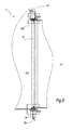
- the valve 2 has a cylindrical overall shape, centered on the axis Y-Y, and comprises an external body 20, inside which a shut-off member 22 is positioned.
- the valve 2 is a butterfly-type valve.
- the shut-off member 22 is a disk and, in the configuration of Figure 2 , the disk 22 is in the shut-off position of the valve 2.
- the valve 2 comprises a service seal 220.
- This seal 220 is disposed in a groove 224 that extends around the entire periphery of the disk 22.
- the service seal 220 seals the valve 2 when the disk 22 is in the shut-off position and the valve is in service.
- the valve 2 likewise comprises a maintenance sealing mechanism M which is disposed upstream of the service seal 220.
- the purpose of this maintenance sealing mechanism M is to seal the valve 2 when it is desired to carry out a maintenance operation on the service seal 220.
- the mechanism M is shown in the retracted position in Figure 4 and in the forward position in Figure 5 .
- This maintenance sealing mechanism M is formed by a plurality of screws 208 and a ring 206. More specifically, the secondary mechanism comprises sixteen screws 208, which are distributed regularly around the central axis Y-Y and which each extend along an axis Y208 parallel to the axis Y-Y.
- These screws 208 are inserted into threads 2040 in an annular frame 204 fixed to the external body 20, in the vicinity of the shut-off member 22 when the latter is in the shut-off position of the valve.
- the annular frame 204 is disposed, radially with respect to the axis Y-Y, around the shut-off member 22 and carries a lining 2042 for supporting the seal 220 in this position.
- the screws 208 each have a threaded part 2082 that has a thread pitch complementary to that of the thread 2040.
- Disposed around each screw 208 and upstream of the thread 2040 into which the latter is inserted is a self-lubricating bush 210 for guiding the screw 208 in rotation and in translation. Each screw 208 bears, upstream, against the ring 206.
- each screw 208 comprises, in the region of its upstream end, a screw head 2080 having a diameter larger than that of the body of the screw.
- This screw head 2080 is inserted into a slot 2060 that extends radially in the ring 206.
- the ring 206 has sixteen slots 2060 which are distributed regularly around the axis Y-Y. The ring 206 is thus secured axially, that is to say along the axis Y208, to each screw 208.
- An axial clearance J1 is defined as the clearance of the screw head 2080 inside the slot 2060. This clearance is measured parallel to the axis Y208 and is greater than 2 mm.
- the clearance J1 between the ring 206 and the screws 208 is such that a deformation of the ring 206 has a limited effect on the screws 208 and, consequently, on the annular frame 204.
- This deformation may be a radial extension or slight twisting about the axis Y-Y.
- These extension and twisting forces are respectively shown in Figure 7 by the arrows F3 and F4. In these two cases, the deformation of the ring 206 exerts a limited force on the screws 208, since the clearance between the screws 208 and the ring 206 authorizes a slight movement of the ring 206.
- the ring 206 is made of a metallic material, in particular austenitic or martensitic stainless steel. Thus, this provides sufficient resistance to the pressure of the fluid inside the valve 2.
- the external body 20 is formed by a downstream flange 200 and a downstream liner 202 that are fixed together by fixing members 212 which, in this example, are screws.
- the external body 20 has an internal volume V20 in which the fluid may flow.
- the downstream liner 202 has sixteen orifices 0202, each aligned with the threads 2040 in the angular frame 204.
- the number of screws 208, of slots 2060, of orifices 0202 and of threads 2040 is identical and is adapted depending on the size of the valve. In this way, it is it possible to insert a tool, such as a socket wrench, into the orifices 0202 in order to access the functional surfaces of the screws 208.
- each screw 208 comprises, in the region of its end opposite the screw head 208, a housing, the walls of which form the functional surfaces of the screw 208 since they are designed to engage with the socket wrench.
- the ring 206 has an internal surface 2062 which is frustoconical and converges in the downstream direction with respect to the axis Y-Y and to the axis Y208 of each screw 208.
- An inclination angle A2062 of the surface 2062 with respect to an axis Y208 is defined. This angle A2062 is in practice between 5° and 20°, preferably close to 12°.
- the screwing of the screw 208 entails, by engagement between the screw head 2080 and the slot 2060 in the ring 206, the axial movement of the ring 206 toward the front and parallel to the axis Y208.
- the ring 206 comes into contact with an outer surface 222 of the shut-off member 22.
- the axial travel, that is to say parallel to the axis Y208, of the movement of the ring 206 in order to pass from the retracted position shown in Figure 4 to the forward position shown in Figure 5 is denoted d1.
- the travel d1 is between 10 and 20 mm depending on the size of the valve. It is precisely this coming into contact of the ring 206 with the shut-off member 22 which makes it possible to seal the valve 2 when the service seal 220 is demounted.
- the ring 206 When the ring 206 has arrived in the forward position, it is subjected to forces associated with the pressure of the upstream fluid since there is no longer a pressure equilibrium between the front and the rear of the ring 206. Specifically, in the retracted position of the ring 206, the fluid is distributed homogeneously around it. There is thus fluid present downstream of the ring which exerts a pressure in the upstream direction. This means that the ring 206 is not subjected to forces associated with the pressure of the fluid.
- the ring 206 carries on its outside a membrane 2064 which is welded, by its two edges 2064A and 2064B, to the upstream and downstream walls of the ring 206.
- the membrane 2064 extends, in a rectilinear manner, along the internal surface 2062 of the ring 206.
- the width and the shape of the membrane 2064 are adapted such that the membrane 2064 deforms in dependence on its interactions with the shut-off member 22.
- An annular volume V2064 present between the internal surface 2062 of the ring 206 and the membrane 2064 is defined.
- This volume V2064 communicates, by way of a plurality of bores 2068 hollowed out at regular intervals in the ring 206, with the internal volume V20 of the valve.
- the fluid flowing inside the pipe arrives at the volume V2064 if the pipe has not been drained.
- This pressure equilibrium makes it possible not only to limit the compression of the membrane 2064 against the ring 206 but also to increase the contact surface area between the ring 206 and the shut-off member 22.
- Figure 6 shows the contact made in a prior art valve R between a mobile ring B and a shut-off member O.
- the contact surface area A between the shut-off member O and the ring B is point-wise in the plane of Figure 6 .
- this has a much greater area than the contact surface area A previously obtained for prior art valves R.
- the outer surface 222 of the shut-off member 22 is inclined in a complementary manner to the internal surface 2062 of the ring 206. This improves sealing, since this is the configuration in which the contact surface area 2064C is largest.
- the maintenance sealing mechanism M comprises a plurality of sensors 214, of the magnetostrictive type, which are inserted into the bores P204 in the annular frame 204 and into housings 0206 in the ring 206, all around the axis Y-Y.
- the sensor 214 has a head 2140 inserted into the ring 206 and is connected, by means of a cable 2142, to a measuring unit (not shown). This sensor 214 makes it possible to measure the forward movement of the ring 206 and thus to know if the maintenance sealing mechanism M is activated or not.
- valve 2 is equipped with sectors 216 which are fixed in the ring 206 by the screws 217. These sectors 216 are self-lubricating sectors which guide the ring 206 in translation along the axis Y-Y with respect to the frame 204.
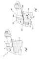
- FIGS 9 to 12 show a sealing mechanism M' according to a second embodiment of the invention.
- FIG. 9 shows a sealing mechanism M' according to a second embodiment of the invention.
- elements that are different from the first embodiment are described below. Elements having the same structure and having the same function retain their reference while the elements that are different from those in the first embodiment bear the same reference followed by a prime.
- the maintenance sealing mechanism M' differs from that in the first embodiment in that the screws 208' are each secured axially to a collar 2084 which is disposed downstream of the screw head 2080. This collar 2084 is immobilized around each screw 208 and has extensions 2084a that are curved toward the rear. Each screw 208' is likewise secured axially, downstream, to a piston 2086.
- the way in which the mechanism M' functions is described in detail below only for a single screw 208', since it is transposable to all the other screws 208'.
- the maintenance sealing mechanism M' comprises a manual pump, which is not shown in the figures, which supplies circuits 242 and 262 that are respectively connected to the outlet of fittings 24 and 26 and in which the pressure of oil injected does not exceed 650 bar.
- the second fitting 26 is supplied with pressurized oil.
- the second fitting 26 supplies the circuit 262 which communicates with a pulling chamber V2086 disposed between the piston 2086 and the annular frame 204.
- the pressurizing of this pulling chamber V2086 entails a force that pushes the hydraulic cylinder 2086 toward the rear. Since the screw 208' is secured to the hydraulic cylinder 2086, it is likewise moved toward the rear and, by means of the slot 2060, drives the ring 206 toward the rear. This direction is shown in Figure 9 by the arrow F6. In parallel, it is necessary to depressurize the pushing chamber V242 in order to optimize the retraction.
- this maintenance sealing mechanism M' is controlled in a semi-automatic manner, since there is no longer a need to manipulate a wrench in order to move the screws 208' forward.
- the forward movement or retraction of the maintenance sealing mechanism M' is controlled from outside the valve by an operator who acts directly on the manual pump. Thus, depending on which movement of the maintenance sealing mechanism M' is desired, the operator actuates the corresponding oil fitting.
- the ring 206 carries, on its internal surface 2062, the membrane 2064 which, during the forward movement of the ring 206, bears against the outer surface 222 of the shut-off member 22.
- the valve 2' thus has a device 226 for immobilizing the mechanism M' once the ring 206 has been moved forward. Specifically, the pressure forces inside the valve 2' are high and tend to push the ring 206 toward the rear. Thus, if the pressure of oil injected into the pushing chamber is not sufficient to compensate these forces (example: leak or rupture of fittings or of a hose), the ring 206 then risks moving toward the rear. In order to avoid this untimely movement of the ring 206, the immobilizing device 226 is actuated when the ring 206 has arrived in its forward position.
- the immobilizing device 226 comprises sixteen rods 2260 which are distributed regularly around the axis Y-Y and are inserted radially with respect to the axis Y-Y into orifices provided in the body of the valve 20.
- the number of rods 226 and the number of screws 208' is adapted depending on the diameter of the valve and the pressure of the fluid. However, the size of the screws 208 and 208' remains the same since the mechanisms must remain compact.
- the ring 204 is thus kept pressed forward and there is no risk of it retracting.
- the membrane 2064 is curvilinear and extends over the upstream wall of the ring 206.
- the surface 222 of the shut-off member 22 is not complementary with the surface 2062 of the ring 206.
- the fixing members 212 are studs.
- the ring 206 comprises a slot 2060 which extends around the entire periphery of the ring.
Abstract
Description
- The present invention relates to a valve which is integrated, in the use configuration, into a fluid distribution network, in particular upstream of a hydraulic machine, and makes it possible, in a controlled manner, to interrupt or authorize the flow of a fluid in a pipe. A hydraulic machine is understood to be a turbine, a pump or a turbine-pump. Such a valve comprises a shut-off member which is rotated by a control device of the valve so as to alternately block or authorize the passage of the fluid.
- The invention is applicable particularly in the field of valves of the butterfly type that are used upstream of a hydraulic machine.
- It is known that a hydraulic installation may comprise a number of hydraulic machines that are all supplied in parallel by an upstream pipe. Thus, during maintenance operations on a valve, in order for example to replace the service seal of the valve, it is necessary to work on the valve in the dry state, that is to say without fluid inside. This has the drawback that it is necessary to stop the inlet of fluid, upstream of the valve, into the pipe, and thus to cease supplying the other hydraulic machines of the installation. This is particularly disadvantageous from an economical point of view, since the production or the distribution of the fluid is stopped during maintenance operations on the valves.
- The same problem arises for valves that are used in other fluid distribution networks.
- In order to solve this problem, it is known to use a maintenance sealing mechanism, the function of which is to seal the valve when a maintenance operation is carried out on the service seal. The maintenance sealing mechanism is thus positioned upstream of the service seal. The maintenance mechanism is, in this case, simply a seal having a profile in the form of a musical note, the round part of which is pressed radially against the shut-off member around the entire periphery of the latter by virtue of rods that are manipulated outside the valve. This mechanism is generally satisfactory. However, the seal is made of an elastomer material which does not make it as robust as a mechanism that uses metallic parts.
- To this end, it is known to use a maintenance sealing mechanism composed of a metal ring that is able to move and has a conical internal surface which is complementary to the external surface of the shut-off member which it surrounds and which, in a controlled manner, is pressed against the latter in order to provide sealing during a maintenance operation. The use of a metal ring provides greater resistance to the pressure of the fluid inside the valve. Furthermore, a seal is disposed in a groove outside the valve and is compressed during contact between the ring and the shut-off member. This makes it possible to seal the assembly. However, if there is a desire to adapt this secondary sealing system to other valves, that is to say to valves having a different shut-off member, it is not certain that the external surface of the shut-off member will be complementary with the internal surface of the ring. Thus, the ring does not adapt correctly to all types of shut-off member.
- The same principle has been adopted for valves that comprise two shut-off members. In this case, a mobile ring, bearing against the upstream shut-off member, compresses a seal made of elastomer. Although this device works, a valve having two shut-off members involves a greater head loss than a valve having a single shut-off member. This is because, when the shut-off member is in the open position, it nevertheless resists the passage of the fluid. This additional head loss results in a weaker jet power at the outlet of the pipe.
- Furthermore, maintenance sealing mechanisms comprising a flexible tongue made of metal material, in particular steel, which is pressed against the shut-off member in order to provide sealing are known from
US-A-4 898 363 ,US-A-3 834 663 andUS-A-4 037 819 . The drawback of these mechanisms is that it is difficult to adapt the geometry of the tongue to that of the shut-off member, this making them poorly adaptable to different types of valve. In addition, they are only applicable for valves having small dimensions, in particular for a diameter of between 200 and 300 mm. Specifically, it is to be feared that, for valves having a diameter of between 1 and 8 m, these flexible tongues made of steel do not provide sufficient resistance to the pressure of the upstream fluid. - It is these drawbacks which the invention intends more particularly to remedy by proposing a valve having a maintenance sealing mechanism that is easily adaptable and is resistant to high pressures.
- To this end, the invention relates to a valve which is integrated into a fluid distribution network and makes it possible, in a selective manner, to interrupt or authorize the flow of a fluid in an axial direction of a pipe, this valve comprising an external body, inside which a shut-off member is disposed, a service seal which, in a shut-off position of the valve, provides sealing between the shut-off member and the body of the valve, and a maintenance sealing mechanism which is disposed upstream of the service seal and which provides sealing during maintenance operations on the service seal. This mechanism comprises a ring which is able to move axially, with respect to the body of the valve, between a retracted position, in which it does not prevent the passage of the fluid, and a forward position, where it bears in a sealing manner against the shut-off member.
- In accordance with the invention, the ring carries, on its internal surface, an elastically deformable membrane which, when the ring is in the forward position, bears, at least partially, against the shut-off member.
- By virtue of the invention, the sealing of the valve during maintenance operations is improved and the maintenance sealing mechanism resists a high pressure inside the valve and is adaptable to different valves.
- According to advantageous but not obligatory aspects of the invention, a valve may incorporate one or more of the following features in any technically admissible combination:
- The ring comprises at least one bore that allows the fluid to flow from an internal volume of the valve to a volume located between the internal surface of the ring and the membrane.
- The maintenance sealing mechanism also comprises a plurality of screws that are able to move the ring in translation in the axial direction.
- The ring comprises at least one slot and the screws each comprise a head that is inserted into the slot.
- The ring comprises as many slots as screws and the slots are distributed regularly around the periphery of the ring, and an axial clearance of the screw in the slot is greater than 2 mm.
- The screws are inserted into threads in an annular frame fixed to the body of the valve and are movable axially by a maneuvering member, in particular by a wrench.
- Each screw is secured to a collar which delimits a pushing chamber, the pressurizing of this pushing chamber involving the forward movement of the screw, while each screw is secured to a piston which delimits a pulling chamber, the pressurizing of this pulling chamber involving the retraction of the screw.
- The valve also comprises a device for immobilizing the ring.
- The immobilizing device comprises at least one locking rod, one end of which is able to be inserted, radially to the axis of the pipe, between the annular frame and the ring, when the ring of the maintenance sealing mechanism is in the forward position.
- The invention also relates to a fluid distribution network comprising at least one valve as described above, installed on a pipe.
- The invention also relates to an installation for converting hydraulic energy into electrical or mechanical energy, or vice versa, comprising a fluid distribution network as mentioned above, wherein the pipe is a supply pipe of a hydraulic machine belonging to the installation.
- Finally, the invention relates to a method for carrying out a maintenance operation on a service seal and/or on a downstream liner of a valve as described above, characterized in that it comprises at least the following steps of:
- a) manipulating the maintenance sealing mechanism such that the ring passes into its forward position,
- b) draining the fluid that remains trapped between the ring and the frame,
- c) removing the service seal and/or the downstream liner,
- d) repositioning or replacing the service seal and/or the downstream liner,
- e) manipulating the maintenance sealing mechanism in order to cause the ring to pass into its retracted position.
- The method may also comprise, for a valve which comprises a device for immobilizing the ring, a step, following step a) and preceding step b), that consists in manipulating the immobilizing device on the valve so as to insert the end of each locking rod radially between the ring and the annular frame.
- The invention will be better understood and further advantages thereof will become more clearly apparent in the light of the following description of the two embodiments of a valve according to the principle of the invention, this description being given solely by way of example and with reference to the appended drawings, in which:
-
Figure 1 is a schematic view of an installation for converting hydraulic energy into electrical or mechanical energy, -
Figure 2 is a front view of a valve according to the invention, -
Figure 3 is a section on the line III-III inFigure 2 , -
Figure 4 is view on a larger scale of the box IV inFigure 3 , which shows a maintenance sealing mechanism, -
Figure 5 is a section similar toFigure 4 in a configuration where the maintenance sealing mechanism is in the forward position, -
Figure 6 is a simplified partial view of a maintenance sealing mechanism belonging to a prior art valve in the use configuration, -
Figure 7 is a simplified partial view, comparable toFigure 6 , of the maintenance sealing mechanism of a valve according to the invention in the use configuration, -
Figure 8 is a view on a larger scale of the box VIII inFigure 3 , -
Figure 9 is a view similar toFigure 4 of a maintenance sealing mechanism belonging to a valve according to a second embodiment of the invention, -
Figure 10 is a view similar toFigure 8 for the maintenance sealing mechanism fromFigure 9 when the latter is in a forward position, -
Figure 11 is a section through an immobilizing device of the maintenance sealing mechanism when the latter is deactivated, -
Figure 12 is a section through the immobilizing device of the maintenance sealing mechanism when the latter is activated. -
Figure 1 shows an example of aninstallation 1 for converting hydraulic energy into electrical energy according to the invention, thishydraulic installation 1 comprising a dam B, an upstream pond R1, a plurality of hydraulic machines M1 and M2 and a downstream pond R2. This type of hydraulic installation makes it possible, inter alia, to store electrical energy in a simple manner: it is conceivable for each hydraulic machine to function as a turbine during the day, that is to say to use hydraulic energy resulting from the difference in height h between the upstream pond R1 and the hydraulic machine M1 or M2 in order for example to rotate an alternator and thus to produce electricity, and to function as a pump at night, thus conveying the water contained in the downstream pond R2 to the upstream pond R1. To this end, the hydraulic installation also comprises a supply pipe C which is connected to the upstream pond R1 and which supplies all of the hydraulic machines, in parallel, by means of a bifurcation D located upstream of all the hydraulic machines. Two types of valves are thus commonly used. Afirst valve 4, known as the pipe head valve, stops or alternatively authorizes the flow in the pipe C. Asecond valve 2, called the guard valve, is located downstream of the bifurcation and upstream of each hydraulic machine. It stops or alternatively supplies the hydraulic machine respectively located downstream of this valve. - A supply line C1 of the hydraulic machine M1 and a supply line C2 of the hydraulic machine M2 are noted. The pipe C and the lines C1 and C2 together form a fluid distribution network.
- The following description thus relates more particularly to a
guard valve 2 for authorizing or stopping the supplying of the hydraulic machine M1. However, it is transposable to apipe head valve 4 to which the invention also applies. All of this is likewise transposable to a fluid distribution network without a hydraulic machine. - The
guard valve 2 is located in a line C1 which directly supplies the hydraulic machine M1 and through which water thus passes in a direction defined by an axis Y-Y. Furthermore defined are an axis Z-Z that is defined as the axis perpendicular to the axis Y-Y in the plane ofFigure 1 , the axis Z-Z being vertical, and an axis X-X perpendicular to the axes Y-Y and Z-Z and to the plane ofFigure 1 . The axes X-X, Y-Y and Z-Z intersect at the center of thevalve 2. - In the rest of the description, the forward direction is defined as the upstream direction and the rearward direction is defined as the downstream direction.
- As can be seen in
Figures 4 and8 , thevalve 2 has a cylindrical overall shape, centered on the axis Y-Y, and comprises anexternal body 20, inside which a shut-off member 22 is positioned. Thevalve 2 is a butterfly-type valve. Thus, the shut-off member 22 is a disk and, in the configuration ofFigure 2 , thedisk 22 is in the shut-off position of thevalve 2. - As can be seen in
Figure 4 , thevalve 2 comprises aservice seal 220. Thisseal 220 is disposed in agroove 224 that extends around the entire periphery of thedisk 22. Theservice seal 220 seals thevalve 2 when thedisk 22 is in the shut-off position and the valve is in service. - The
valve 2 likewise comprises a maintenance sealing mechanism M which is disposed upstream of theservice seal 220. The purpose of this maintenance sealing mechanism M is to seal thevalve 2 when it is desired to carry out a maintenance operation on theservice seal 220. The mechanism M is shown in the retracted position inFigure 4 and in the forward position inFigure 5 . This maintenance sealing mechanism M is formed by a plurality ofscrews 208 and aring 206. More specifically, the secondary mechanism comprises sixteenscrews 208, which are distributed regularly around the central axis Y-Y and which each extend along an axis Y208 parallel to the axis Y-Y. Thesescrews 208 are inserted intothreads 2040 in anannular frame 204 fixed to theexternal body 20, in the vicinity of the shut-off member 22 when the latter is in the shut-off position of the valve. Theannular frame 204 is disposed, radially with respect to the axis Y-Y, around the shut-off member 22 and carries alining 2042 for supporting theseal 220 in this position. Thescrews 208 each have a threadedpart 2082 that has a thread pitch complementary to that of thethread 2040. Disposed around eachscrew 208 and upstream of thethread 2040 into which the latter is inserted is a self-lubricating bush 210 for guiding thescrew 208 in rotation and in translation. Eachscrew 208 bears, upstream, against thering 206. - Specifically, each
screw 208 comprises, in the region of its upstream end, ascrew head 2080 having a diameter larger than that of the body of the screw. Thisscrew head 2080 is inserted into aslot 2060 that extends radially in thering 206. In practice, thering 206 has sixteenslots 2060 which are distributed regularly around the axis Y-Y. Thering 206 is thus secured axially, that is to say along the axis Y208, to eachscrew 208. An axial clearance J1 is defined as the clearance of thescrew head 2080 inside theslot 2060. This clearance is measured parallel to the axis Y208 and is greater than 2 mm. - The clearance J1 between the
ring 206 and thescrews 208 is such that a deformation of thering 206 has a limited effect on thescrews 208 and, consequently, on theannular frame 204. Specifically, when thevalve 2 is in service, the pressure of the fluid inside the valve tends to deform thering 206. This deformation may be a radial extension or slight twisting about the axis Y-Y. These extension and twisting forces are respectively shown inFigure 7 by the arrows F3 and F4. In these two cases, the deformation of thering 206 exerts a limited force on thescrews 208, since the clearance between thescrews 208 and thering 206 authorizes a slight movement of thering 206. - The
ring 206 is made of a metallic material, in particular austenitic or martensitic stainless steel. Thus, this provides sufficient resistance to the pressure of the fluid inside thevalve 2. - The
external body 20 is formed by adownstream flange 200 and adownstream liner 202 that are fixed together by fixingmembers 212 which, in this example, are screws. Theexternal body 20 has an internal volume V20 in which the fluid may flow. Thedownstream liner 202 has sixteenorifices 0202, each aligned with thethreads 2040 in theangular frame 204. The number ofscrews 208, ofslots 2060, oforifices 0202 and ofthreads 2040 is identical and is adapted depending on the size of the valve. In this way, it is it possible to insert a tool, such as a socket wrench, into theorifices 0202 in order to access the functional surfaces of thescrews 208. To this end, eachscrew 208 comprises, in the region of its end opposite thescrew head 208, a housing, the walls of which form the functional surfaces of thescrew 208 since they are designed to engage with the socket wrench. - The
ring 206 has aninternal surface 2062 which is frustoconical and converges in the downstream direction with respect to the axis Y-Y and to the axis Y208 of eachscrew 208. An inclination angle A2062 of thesurface 2062 with respect to an axis Y208 is defined. This angle A2062 is in practice between 5° and 20°, preferably close to 12°. - In the retracted position of the
ring 206 shown inFigure 4 , said ring is not subjected to forces associated with the pressure of the fluid, since there is a pressure equilibrium between the front and rear of thering 206. The manipulation of the maintenance sealing mechanism M makes it possible to pass from the configuration inFigure 4 to the configuration inFigure 5 . Although the sealing mechanism M has sixteenscrews 208 that all act on thering 206, only the action of onescrew 208 on thering 206 is described in detail below, since this is transposable to theother screws 208 of the mechanism M. For this purpose, it is appropriate to insert a tool (not shown in the figures) into eachorifice 0202 of thedownstream liner 202 in order to access the functional surfaces of thecorresponding screw 208. A tightening torque can then be applied in order to move the screw forward along the axis Y208. The forward movement of thescrew 208 is shown inFigure 4 by the arrow F1. - The screwing of the
screw 208 entails, by engagement between thescrew head 2080 and theslot 2060 in thering 206, the axial movement of thering 206 toward the front and parallel to the axis Y208. - Thus, at the end of its travel, the
ring 206 comes into contact with anouter surface 222 of the shut-off member 22. The axial travel, that is to say parallel to the axis Y208, of the movement of thering 206 in order to pass from the retracted position shown inFigure 4 to the forward position shown inFigure 5 is denoted d1. In practice, the travel d1 is between 10 and 20 mm depending on the size of the valve. It is precisely this coming into contact of thering 206 with the shut-off member 22 which makes it possible to seal thevalve 2 when theservice seal 220 is demounted. - In this configuration, it is possible to remove the
seal 220 and also thedownstream liner 202 in order to repair or replace them. - When the
ring 206 has arrived in the forward position, it is subjected to forces associated with the pressure of the upstream fluid since there is no longer a pressure equilibrium between the front and the rear of thering 206. Specifically, in the retracted position of thering 206, the fluid is distributed homogeneously around it. There is thus fluid present downstream of the ring which exerts a pressure in the upstream direction. This means that thering 206 is not subjected to forces associated with the pressure of the fluid. - However, once the
ring 206 is in the forward position and it is desired to return it to its retracted position, the fluid present inside a volume V206 disposed downstream of thering 206 resists the retraction of thering 206. For this reason, it is suitable, in parallel with the forward movement of thering 206, to drain the fluid present inside the volume V206. This operation is carried out by means ofchannels 2002 hollowed out in thedownstream flange 200 which communicate with the volume V206. To this end,manual valves 218 that can be maneuvered outside the valve are used. - The effectiveness of the maintenance sealing mechanism M resides on the quality of the contact brought about between the
ring 206 and theouter surface 222 of the shut-off member 22. To this end, and as is illustrated best inFigure 7 , thering 206 carries on its outside amembrane 2064 which is welded, by its twoedges ring 206. Thus, themembrane 2064 extends, in a rectilinear manner, along theinternal surface 2062 of thering 206. The width and the shape of themembrane 2064 are adapted such that themembrane 2064 deforms in dependence on its interactions with the shut-off member 22. - An annular volume V2064 present between the
internal surface 2062 of thering 206 and themembrane 2064 is defined. This volume V2064 communicates, by way of a plurality ofbores 2068 hollowed out at regular intervals in thering 206, with the internal volume V20 of the valve. Thus, the fluid flowing inside the pipe arrives at the volume V2064 if the pipe has not been drained. There is thus a pressure equilibrium on either side of themembrane 2064. This pressure equilibrium makes it possible not only to limit the compression of themembrane 2064 against thering 206 but also to increase the contact surface area between thering 206 and the shut-off member 22. - Specifically,
Figure 6 shows the contact made in a prior art valve R between a mobile ring B and a shut-off member O. It will be noted that the contact surface area A between the shut-off member O and the ring B is point-wise in the plane ofFigure 6 . By way of comparison betweenFigures 6 and 7 , and with a contact surface area between themembrane 2064 and the shut-off member 22 being denoted 2064C, it will be noted that this has a much greater area than the contact surface area A previously obtained for prior art valves R. - Furthermore, the
outer surface 222 of the shut-off member 22 is inclined in a complementary manner to theinternal surface 2062 of thering 206. This improves sealing, since this is the configuration in which thecontact surface area 2064C is largest. - As can be seen in
Figure 8 , the maintenance sealing mechanism M comprises a plurality ofsensors 214, of the magnetostrictive type, which are inserted into the bores P204 in theannular frame 204 and intohousings 0206 in thering 206, all around the axis Y-Y. In the following text, only onesensor 214 is described in detail, since theother sensors 214 function in an identical manner. Thesensor 214 has ahead 2140 inserted into thering 206 and is connected, by means of acable 2142, to a measuring unit (not shown). Thissensor 214 makes it possible to measure the forward movement of thering 206 and thus to know if the maintenance sealing mechanism M is activated or not. - Furthermore, the
valve 2 is equipped withsectors 216 which are fixed in thering 206 by thescrews 217. Thesesectors 216 are self-lubricating sectors which guide thering 206 in translation along the axis Y-Y with respect to theframe 204. - With the position of the maintenance sealing mechanism M being known, it is possible to prevent the shut-off member opening while the maintenance sealing mechanism M is in the forward position.
- In the opposite direction, in order to retract the
ring 206, it is appropriate to apply a tightening torque opposite to that exerted in order to move thescrew 208 forward. In this way, thescrew 208 is retracted and, consequently, thering 206 is retracted since the latter is axially secured to thescrew 208. This retraction is shown, inFigure 5 , by an arrow F2. -
Figures 9 to 12 show a sealing mechanism M' according to a second embodiment of the invention. For the sake of clarity of the description, only the elements that are different from the first embodiment are described below. Elements having the same structure and having the same function retain their reference while the elements that are different from those in the first embodiment bear the same reference followed by a prime. - The maintenance sealing mechanism M' differs from that in the first embodiment in that the screws 208' are each secured axially to a
collar 2084 which is disposed downstream of thescrew head 2080. Thiscollar 2084 is immobilized around eachscrew 208 and hasextensions 2084a that are curved toward the rear. Each screw 208' is likewise secured axially, downstream, to apiston 2086. The way in which the mechanism M' functions is described in detail below only for a single screw 208', since it is transposable to all the other screws 208'. - The forward movement and retraction of the maintenance sealing mechanism M' is carried out by injection of oil. To this end, the maintenance sealing mechanism M' comprises a manual pump, which is not shown in the figures, which supplies
circuits fittings - In order to move the maintenance sealing mechanism M' forward, that is to say in order to pass from the configuration in
Figure 9 to that inFigure 10 , it is appropriate to supply the fitting 24 with pressurized oil. Thesupply circuit 242 opens and leads into a pushing chamber V242 in contact withextensions 2084a of thecollar 2084 of the screw 208'. The injection of oil into thechannel 242 thus brings about a pushing force on theextensions 2084a, which causes the screw 208' to move forward. This movement is shown inFigure 10 by the arrow F5. In similar manner to the first embodiment, the screw 208' pushes thering 206 forward into contact with the outer surface of the shut-off member 22. - In the opposite direction, when it is appropriate to deactivate the maintenance sealing mechanism M', the
second fitting 26 is supplied with pressurized oil. Thesecond fitting 26 supplies thecircuit 262 which communicates with a pulling chamber V2086 disposed between thepiston 2086 and theannular frame 204. The pressurizing of this pulling chamber V2086 entails a force that pushes thehydraulic cylinder 2086 toward the rear. Since the screw 208' is secured to thehydraulic cylinder 2086, it is likewise moved toward the rear and, by means of theslot 2060, drives thering 206 toward the rear. This direction is shown inFigure 9 by the arrow F6. In parallel, it is necessary to depressurize the pushing chamber V242 in order to optimize the retraction. - In comparison with the first embodiment, it is noted that this maintenance sealing mechanism M' is controlled in a semi-automatic manner, since there is no longer a need to manipulate a wrench in order to move the screws 208' forward. The forward movement or retraction of the maintenance sealing mechanism M' is controlled from outside the valve by an operator who acts directly on the manual pump. Thus, depending on which movement of the maintenance sealing mechanism M' is desired, the operator actuates the corresponding oil fitting.
- If the semi-automatic system malfunctions, it is possible to return to a manual system by removing the
piston 2086 from thescrew 208. This operation is possible since said piston is accessible through theorifices 0202 in thedownstream liner 202. Once thepiston 2086 has been removed, the screw 208' can be manipulated as desired. - In a similar manner to the first embodiment, the
ring 206 carries, on itsinternal surface 2062, themembrane 2064 which, during the forward movement of thering 206, bears against theouter surface 222 of the shut-off member 22. - However, during a maintenance operation on the service seal, it is necessary to ensure security by locking the system in the forward position in case of a head loss in the pushing chamber V242. The valve 2' thus has a
device 226 for immobilizing the mechanism M' once thering 206 has been moved forward. Specifically, the pressure forces inside the valve 2' are high and tend to push thering 206 toward the rear. Thus, if the pressure of oil injected into the pushing chamber is not sufficient to compensate these forces (example: leak or rupture of fittings or of a hose), thering 206 then risks moving toward the rear. In order to avoid this untimely movement of thering 206, the immobilizingdevice 226 is actuated when thering 206 has arrived in its forward position. - More specifically, and as can be seen in
Figures 11 and 12 , the immobilizingdevice 226 comprises sixteenrods 2260 which are distributed regularly around the axis Y-Y and are inserted radially with respect to the axis Y-Y into orifices provided in the body of thevalve 20. The number ofrods 226 and the number of screws 208' is adapted depending on the diameter of the valve and the pressure of the fluid. However, the size of thescrews 208 and 208' remains the same since the mechanisms must remain compact. When the maintenance sealing mechanism has arrived in its forward position, the operator inserts all therods 2260 successively into the interior of the volume V206 formed between thering 206 and theannular frame 204. This movement is shown, inFigure 11 , by an arrow F7. The width of theend 2260A of therods 2260 is designed for interposition between thering 206 and theannular frame 204. Once therods 2260 have been inserted, they are held in position by means of a non-reversible screw/nut system. - The
ring 204 is thus kept pressed forward and there is no risk of it retracting. - When it is desired to retract the
ring 206, it is appropriate to remove all the ends 2060A of therods 2260 from the volume V206. This movement is shown inFigure 12 by an arrow F8. Theimmobilizing device 226 thus no longer prevents the retraction of thering 206. In a variant which is not shown, themembrane 2064 is curvilinear and extends over the upstream wall of thering 206. - In a variant which is not shown, it is possible to use, instead of the
sensors 214, another type ofring 206 movement sensor, in particular a sensor of the inductive type, which measures the movement of thescrew 208. - In a variant which is not shown, the
surface 222 of the shut-off member 22 is not complementary with thesurface 2062 of thering 206. - In a variant, the fixing
members 212 are studs. - In a variant which is not shown, the
ring 206 comprises aslot 2060 which extends around the entire periphery of the ring. - The variants and embodiments mentioned above may be combined in order to provide new embodiments of the invention.
Claims (13)
- Valve (2; 2') which is integrated into a fluid distribution network and makes it possible, in a selective manner, to interrupt or authorize the flow of a fluid in an axial direction (Y-Y) of a pipe, this valve comprising:- an external body (20), inside which a shut-off member (22) is disposed,- a service seal (220) which, in a shut-off position of the valve, provides sealing between the shut-off member and the body (20) of the valve, and- a maintenance sealing mechanism (M; M') which is disposed upstream of the service seal (220) and which provides sealing during maintenance operations on the service seal (220), this mechanism (M; M') comprising a ring (206) which is able to move axially, with respect to the body (20) of the valve, between a retracted position (Figure 4), in which it does not prevent the passage of the fluid, and a forward position (Figure 5), where it bears in a sealing manner against the shut-off member (22),characterized in that the ring carries, on its internal surface (2062), an elastically deformable membrane (2064) which, when the ring is in the forward position, bears, at least partially, against the shut-off member (22).
- Valve (2; 2') according to Claim 1, characterized in that the ring (206) comprises at least one bore (2068) that allows the fluid to flow from an internal volume (V20) of the valve to a volume (V2064) located between the internal surface (2062) of the ring and the membrane (2064).
- Valve (2; 2') according to either of the preceding claims, characterized in that the maintenance sealing mechanism (M; M') also comprises a plurality of screws (208; 208') that are able to move the ring (206) in translation in the axial direction (Y-Y).
- Valve (2; 2') according to Claim 3, characterized in that the ring (206) comprises at least one slot (2060), and in that the screws (208) each comprise a head (2080) that is inserted into the slot (2060).
- Valve (2; 2') according to Claim 4, characterized in that the ring (206) comprises as many slots (2060) as screws (208), and in that the slots are distributed regularly around the entire periphery of the ring (206), and in that an axial clearance (J1) of the screw (208; 208') in the slot (2060) is greater than 2 mm.
- Valve (2) according to one of Claims 3 to 5, characterized in that the screws (208) are inserted into threads (2040) in an annular frame (204) fixed to the body (20) of the valve and are movable axially (Y208) by a maneuvering member, in particular by a wrench.
- Valve (2') according to one of Claims 1 to 5, characterized in that each screw (208') is secured to a collar (2084) which delimits a pushing chamber (V242), the pressurizing of this pushing chamber involving the forward movement of the screw, and in that each screw is secured to a piston (2086) which delimits a pulling chamber (V2086), the pressurizing of this pulling chamber (V2086) involving the retraction of the screw.
- Valve (2') according to Claim 7, characterized in that the valve (2') also comprises a device (266) for immobilizing the ring (206).
- Valve (2') according to Claim 8, characterized in that the immobilizing device (226) comprises at least one locking rod (2660), one end (2260A) of which is able to be inserted, radially to the axis (Y-Y) of the pipe, between the annular frame (204) and the ring (206), when the ring (206) of the maintenance sealing mechanism (M') is in the forward position (Figure 5).
- Fluid distribution network (C, C1, C2), characterized in that it comprises at least one valve according to one of the preceding claims, installed on a pipe.
- Installation (1) for converting hydraulic energy into electrical or mechanical energy, or vice versa, characterized in that it comprises a fluid distribution network (C, C1, C2) according to Claim 10, wherein the pipe is a supply pipe (C1) of a hydraulic machine (M1) belonging to the installation.
- Method for carrying out a maintenance operation on a service seal (220) and/or on a downstream liner (202) of a valve (2; 2') according to one of Claims 1 to 9, characterized in that it comprises at least the following steps of:a) manipulating the maintenance sealing mechanism (M; M') such that theb) draining the fluid that remains trapped between the ring (206) and the frame (204),
ring (206) passes into its forward position (Figure 5, Figure 10),c) removing the service seal (220) and/or the downstream liner (202),d) repositioning or replacing the service seal and/or the downstream liner (202),e) manipulating the maintenance sealing mechanism (M; M') in order to cause the ring (206) to pass into its retracted position (Figure 4; Figure 9). - Method according to Claim 12, used for a valve according to Claim 9, characterized in that it also comprises a step, following step a) and preceding step b), that consists in manipulating the immobilizing device (226) on the valve (2') so as to insert the end (2260A) of each locking rod (2260) radially between the ring (206) and the annular frame (204).
Applications Claiming Priority (1)
| Application Number | Priority Date | Filing Date | Title |
|---|---|---|---|
| FR1353074A FR3004232A1 (en) | 2013-04-05 | 2013-04-05 | INTEGRATED VALVE IN A FLUID DISTRIBUTION NETWORK, NETWORK AND ENERGY CONVERSION INSTALLATION COMPRISING SUCH A FAUCET |
Publications (2)
| Publication Number | Publication Date |
|---|---|
| EP2787261A1 true EP2787261A1 (en) | 2014-10-08 |
| EP2787261B1 EP2787261B1 (en) | 2016-06-29 |
Family
ID=48906282
Family Applications (1)
| Application Number | Title | Priority Date | Filing Date |
|---|---|---|---|
| EP14163221.6A Not-in-force EP2787261B1 (en) | 2013-04-05 | 2014-04-02 | Valve integrated into a fluid distribution network, network and energy conversion installation comprising such a valve |
Country Status (6)
| Country | Link |
|---|---|
| EP (1) | EP2787261B1 (en) |
| BR (1) | BR102014008142A2 (en) |
| CA (1) | CA2847941C (en) |
| CL (1) | CL2014000834A1 (en) |
| FR (1) | FR3004232A1 (en) |
| IN (1) | IN2014DE00978A (en) |
Cited By (1)
| Publication number | Priority date | Publication date | Assignee | Title |
|---|---|---|---|---|
| CN115962289A (en) * | 2022-11-03 | 2023-04-14 | 宁波一机阀门制造有限公司 | Intelligent bidirectional metal self-pressing sealing butterfly valve with self-generated power and control system thereof |
Citations (9)
| Publication number | Priority date | Publication date | Assignee | Title |
|---|---|---|---|---|
| GB197000A (en) * | 1922-02-02 | 1923-05-02 | John Beardsell Broadhead | An improvement in or relating to valves |
| US3834663A (en) | 1971-12-09 | 1974-09-10 | Jamesbury Corp | Metal seat butterfly valve |
| US4037819A (en) | 1976-03-03 | 1977-07-26 | Kamyr Valves Inc. | Butterfly valve having metal-to-metal sealing with conical angle-transported vane |
| CH637455A5 (en) * | 1980-08-27 | 1983-07-29 | Vevey Atel Const Mec | Butterfly valve |
| FR2573170A1 (en) * | 1984-11-09 | 1986-05-16 | Neyrpic | Butterfly valve with double sealing |
| AT388979B (en) * | 1987-03-17 | 1989-09-25 | Voest Alpine Ag | FLAP VALVE |
| US4898363A (en) | 1988-06-10 | 1990-02-06 | Charles Winn (Valves) Limited | Butterfly and ball valves |
| WO2002040903A1 (en) * | 2000-11-17 | 2002-05-23 | Mks Instruments, Inc. | Valve flapper with dynamic circumference seal |
| JP2005147234A (en) * | 2003-11-13 | 2005-06-09 | Toshiba Corp | Biplane valve and method for changing its packing |
-
2013
- 2013-04-05 FR FR1353074A patent/FR3004232A1/en not_active Withdrawn
-
2014
- 2014-04-01 CA CA2847941A patent/CA2847941C/en not_active Expired - Fee Related
- 2014-04-02 EP EP14163221.6A patent/EP2787261B1/en not_active Not-in-force
- 2014-04-04 BR BR102014008142A patent/BR102014008142A2/en not_active IP Right Cessation
- 2014-04-04 IN IN978DE2014 patent/IN2014DE00978A/en unknown
- 2014-04-04 CL CL2014000834A patent/CL2014000834A1/en unknown
Patent Citations (9)
| Publication number | Priority date | Publication date | Assignee | Title |
|---|---|---|---|---|
| GB197000A (en) * | 1922-02-02 | 1923-05-02 | John Beardsell Broadhead | An improvement in or relating to valves |
| US3834663A (en) | 1971-12-09 | 1974-09-10 | Jamesbury Corp | Metal seat butterfly valve |
| US4037819A (en) | 1976-03-03 | 1977-07-26 | Kamyr Valves Inc. | Butterfly valve having metal-to-metal sealing with conical angle-transported vane |
| CH637455A5 (en) * | 1980-08-27 | 1983-07-29 | Vevey Atel Const Mec | Butterfly valve |
| FR2573170A1 (en) * | 1984-11-09 | 1986-05-16 | Neyrpic | Butterfly valve with double sealing |
| AT388979B (en) * | 1987-03-17 | 1989-09-25 | Voest Alpine Ag | FLAP VALVE |
| US4898363A (en) | 1988-06-10 | 1990-02-06 | Charles Winn (Valves) Limited | Butterfly and ball valves |
| WO2002040903A1 (en) * | 2000-11-17 | 2002-05-23 | Mks Instruments, Inc. | Valve flapper with dynamic circumference seal |
| JP2005147234A (en) * | 2003-11-13 | 2005-06-09 | Toshiba Corp | Biplane valve and method for changing its packing |
Cited By (2)
| Publication number | Priority date | Publication date | Assignee | Title |
|---|---|---|---|---|
| CN115962289A (en) * | 2022-11-03 | 2023-04-14 | 宁波一机阀门制造有限公司 | Intelligent bidirectional metal self-pressing sealing butterfly valve with self-generated power and control system thereof |
| CN115962289B (en) * | 2022-11-03 | 2023-12-19 | 宁波一机阀门制造有限公司 | Self-generated power intelligent bidirectional metal self-pressing sealing butterfly valve and control system thereof |
Also Published As
| Publication number | Publication date |
|---|---|
| EP2787261B1 (en) | 2016-06-29 |
| IN2014DE00978A (en) | 2015-06-05 |
| BR102014008142A2 (en) | 2014-12-23 |
| CA2847941A1 (en) | 2014-10-05 |
| FR3004232A1 (en) | 2014-10-10 |
| CA2847941C (en) | 2016-11-22 |
| CL2014000834A1 (en) | 2014-08-29 |
Similar Documents
| Publication | Publication Date | Title |
|---|---|---|
| CA3000679C (en) | Sealing high pressure flow devices | |
| US10677389B2 (en) | Check valve | |
| US6015134A (en) | Pneumatic actuator assembly | |
| EP2449266B1 (en) | Methods and apparatus to charge accumulator apparatus | |
| RU121025U1 (en) | DEVICE FOR PIPELINE SEALING WHEN REPAIRING A BALL VALVE UNDER PRESSURE | |
| US5690139A (en) | Valve construction | |
| EP3022471B1 (en) | Axial fluid valves | |
| KR100950571B1 (en) | Relief valve of heavy equipment | |
| CN102272497A (en) | Fluid valves having an integral safety shut-off | |
| US20180372231A1 (en) | Pipeline control unit | |
| CA2847941C (en) | Valve integrated into a fluid distribution network, network and energy conversion installation comprising such a valve | |
| US20140097363A1 (en) | Floating seal retainer | |
| KR101685195B1 (en) | Ball valve with a dual pressure measuring device | |
| US20140034860A1 (en) | Industrial valve | |
| RU205201U1 (en) | All-mode shut-off and control valve | |
| KR101658102B1 (en) | A repairing apparatus of a pipeline and the method | |
| CN205190930U (en) | Release having a double meaning double break valve of function of improved generation area | |
| RU114742U1 (en) | SAFETY DEVICE FOR REPAIR OF A BALL VALVE UNDER PRESSURE (OPTIONS) | |
| KR101782196B1 (en) | Valve including a device for immobilizing a journal, energy conversion installation/fluid distribution network including such a valve and method of demounting such a valve | |
| US2975800A (en) | Internal-cylinder-operated valve | |
| CN110425323B (en) | Stop valve | |
| KR101425301B1 (en) | The valve sealant fitting double joint structure | |
| RU160383U1 (en) | HYDRAULIC VALVE | |
| KR101711137B1 (en) | Method for mending of water leakage interception inwater main and method thereof | |
| KR101782426B1 (en) | Control device of relief valve with test gag |
Legal Events
| Date | Code | Title | Description |
|---|---|---|---|
| PUAI | Public reference made under article 153(3) epc to a published international application that has entered the european phase |
Free format text: ORIGINAL CODE: 0009012 |
|
| 17P | Request for examination filed |
Effective date: 20140402 |
|
| AK | Designated contracting states |
Kind code of ref document: A1 Designated state(s): AL AT BE BG CH CY CZ DE DK EE ES FI FR GB GR HR HU IE IS IT LI LT LU LV MC MK MT NL NO PL PT RO RS SE SI SK SM TR |
|
| AX | Request for extension of the european patent |
Extension state: BA ME |
|
| 17Q | First examination report despatched |
Effective date: 20150527 |
|
| GRAP | Despatch of communication of intention to grant a patent |
Free format text: ORIGINAL CODE: EPIDOSNIGR1 |
|
| INTG | Intention to grant announced |
Effective date: 20160128 |
|
| GRAS | Grant fee paid |
Free format text: ORIGINAL CODE: EPIDOSNIGR3 |
|
| GRAA | (expected) grant |
Free format text: ORIGINAL CODE: 0009210 |
|
| AK | Designated contracting states |
Kind code of ref document: B1 Designated state(s): AL AT BE BG CH CY CZ DE DK EE ES FI FR GB GR HR HU IE IS IT LI LT LU LV MC MK MT NL NO PL PT RO RS SE SI SK SM TR |
|
| REG | Reference to a national code |
Ref country code: GB Ref legal event code: FG4D |
|
| REG | Reference to a national code |
Ref country code: CH Ref legal event code: EP |
|
| REG | Reference to a national code |
Ref country code: AT Ref legal event code: REF Ref document number: 809375 Country of ref document: AT Kind code of ref document: T Effective date: 20160715 |
|
| REG | Reference to a national code |
Ref country code: IE Ref legal event code: FG4D |
|
| REG | Reference to a national code |
Ref country code: DE Ref legal event code: R096 Ref document number: 602014002442 Country of ref document: DE |
|
| REG | Reference to a national code |
Ref country code: LT Ref legal event code: MG4D |
|
| PG25 | Lapsed in a contracting state [announced via postgrant information from national office to epo] |
Ref country code: NO Free format text: LAPSE BECAUSE OF FAILURE TO SUBMIT A TRANSLATION OF THE DESCRIPTION OR TO PAY THE FEE WITHIN THE PRESCRIBED TIME-LIMIT Effective date: 20160929 Ref country code: FI Free format text: LAPSE BECAUSE OF FAILURE TO SUBMIT A TRANSLATION OF THE DESCRIPTION OR TO PAY THE FEE WITHIN THE PRESCRIBED TIME-LIMIT Effective date: 20160629 Ref country code: LT Free format text: LAPSE BECAUSE OF FAILURE TO SUBMIT A TRANSLATION OF THE DESCRIPTION OR TO PAY THE FEE WITHIN THE PRESCRIBED TIME-LIMIT Effective date: 20160629 |
|
| REG | Reference to a national code |
Ref country code: NL Ref legal event code: MP Effective date: 20160629 |
|
| PG25 | Lapsed in a contracting state [announced via postgrant information from national office to epo] |
Ref country code: RS Free format text: LAPSE BECAUSE OF FAILURE TO SUBMIT A TRANSLATION OF THE DESCRIPTION OR TO PAY THE FEE WITHIN THE PRESCRIBED TIME-LIMIT Effective date: 20160629 Ref country code: SE Free format text: LAPSE BECAUSE OF FAILURE TO SUBMIT A TRANSLATION OF THE DESCRIPTION OR TO PAY THE FEE WITHIN THE PRESCRIBED TIME-LIMIT Effective date: 20160629 Ref country code: HR Free format text: LAPSE BECAUSE OF FAILURE TO SUBMIT A TRANSLATION OF THE DESCRIPTION OR TO PAY THE FEE WITHIN THE PRESCRIBED TIME-LIMIT Effective date: 20160629 Ref country code: NL Free format text: LAPSE BECAUSE OF FAILURE TO SUBMIT A TRANSLATION OF THE DESCRIPTION OR TO PAY THE FEE WITHIN THE PRESCRIBED TIME-LIMIT Effective date: 20160629 Ref country code: LV Free format text: LAPSE BECAUSE OF FAILURE TO SUBMIT A TRANSLATION OF THE DESCRIPTION OR TO PAY THE FEE WITHIN THE PRESCRIBED TIME-LIMIT Effective date: 20160629 |
|
| PG25 | Lapsed in a contracting state [announced via postgrant information from national office to epo] |
Ref country code: SK Free format text: LAPSE BECAUSE OF FAILURE TO SUBMIT A TRANSLATION OF THE DESCRIPTION OR TO PAY THE FEE WITHIN THE PRESCRIBED TIME-LIMIT Effective date: 20160629 Ref country code: CZ Free format text: LAPSE BECAUSE OF FAILURE TO SUBMIT A TRANSLATION OF THE DESCRIPTION OR TO PAY THE FEE WITHIN THE PRESCRIBED TIME-LIMIT Effective date: 20160629 Ref country code: RO Free format text: LAPSE BECAUSE OF FAILURE TO SUBMIT A TRANSLATION OF THE DESCRIPTION OR TO PAY THE FEE WITHIN THE PRESCRIBED TIME-LIMIT Effective date: 20160629 Ref country code: IS Free format text: LAPSE BECAUSE OF FAILURE TO SUBMIT A TRANSLATION OF THE DESCRIPTION OR TO PAY THE FEE WITHIN THE PRESCRIBED TIME-LIMIT Effective date: 20161029 Ref country code: EE Free format text: LAPSE BECAUSE OF FAILURE TO SUBMIT A TRANSLATION OF THE DESCRIPTION OR TO PAY THE FEE WITHIN THE PRESCRIBED TIME-LIMIT Effective date: 20160629 |
|
| PG25 | Lapsed in a contracting state [announced via postgrant information from national office to epo] |
Ref country code: ES Free format text: LAPSE BECAUSE OF FAILURE TO SUBMIT A TRANSLATION OF THE DESCRIPTION OR TO PAY THE FEE WITHIN THE PRESCRIBED TIME-LIMIT Effective date: 20160629 Ref country code: PT Free format text: LAPSE BECAUSE OF FAILURE TO SUBMIT A TRANSLATION OF THE DESCRIPTION OR TO PAY THE FEE WITHIN THE PRESCRIBED TIME-LIMIT Effective date: 20161031 Ref country code: SM Free format text: LAPSE BECAUSE OF FAILURE TO SUBMIT A TRANSLATION OF THE DESCRIPTION OR TO PAY THE FEE WITHIN THE PRESCRIBED TIME-LIMIT Effective date: 20160629 Ref country code: PL Free format text: LAPSE BECAUSE OF FAILURE TO SUBMIT A TRANSLATION OF THE DESCRIPTION OR TO PAY THE FEE WITHIN THE PRESCRIBED TIME-LIMIT Effective date: 20160629 Ref country code: BE Free format text: LAPSE BECAUSE OF FAILURE TO SUBMIT A TRANSLATION OF THE DESCRIPTION OR TO PAY THE FEE WITHIN THE PRESCRIBED TIME-LIMIT Effective date: 20160629 |
|
| REG | Reference to a national code |
Ref country code: DE Ref legal event code: R097 Ref document number: 602014002442 Country of ref document: DE |
|
| REG | Reference to a national code |
Ref country code: FR Ref legal event code: PLFP Year of fee payment: 4 |
|
| REG | Reference to a national code |
Ref country code: CH Ref legal event code: PFA Owner name: GE RENEWABLE TECHNOLOGIES, FR Free format text: FORMER OWNER: ALSTOM RENEWABLE TECHNOLOGIES, FR |
|
| PG25 | Lapsed in a contracting state [announced via postgrant information from national office to epo] |
Ref country code: DK Free format text: LAPSE BECAUSE OF FAILURE TO SUBMIT A TRANSLATION OF THE DESCRIPTION OR TO PAY THE FEE WITHIN THE PRESCRIBED TIME-LIMIT Effective date: 20160629 |
|
| 26N | No opposition filed |
Effective date: 20170330 |
|
| PLBE | No opposition filed within time limit |
Free format text: ORIGINAL CODE: 0009261 |
|
| STAA | Information on the status of an ep patent application or granted ep patent |
Free format text: STATUS: NO OPPOSITION FILED WITHIN TIME LIMIT |
|
| PG25 | Lapsed in a contracting state [announced via postgrant information from national office to epo] |
Ref country code: SI Free format text: LAPSE BECAUSE OF FAILURE TO SUBMIT A TRANSLATION OF THE DESCRIPTION OR TO PAY THE FEE WITHIN THE PRESCRIBED TIME-LIMIT Effective date: 20160629 Ref country code: BG Free format text: LAPSE BECAUSE OF FAILURE TO SUBMIT A TRANSLATION OF THE DESCRIPTION OR TO PAY THE FEE WITHIN THE PRESCRIBED TIME-LIMIT Effective date: 20160929 |
|
| REG | Reference to a national code |
Ref country code: AT Ref legal event code: HC Ref document number: 809375 Country of ref document: AT Kind code of ref document: T Owner name: GE RENEWABLE TECHNOLOGIES, FR Effective date: 20170814 |
|
| REG | Reference to a national code |
Ref country code: FR Ref legal event code: CD Owner name: GE RENEWABLE TECHNOLOGIES, FR Effective date: 20170929 Ref country code: DE Ref legal event code: R119 Ref document number: 602014002442 Country of ref document: DE |
|
| REG | Reference to a national code |
Ref country code: IE Ref legal event code: MM4A |
|
| PG25 | Lapsed in a contracting state [announced via postgrant information from national office to epo] |
Ref country code: DE Free format text: LAPSE BECAUSE OF NON-PAYMENT OF DUE FEES Effective date: 20171103 Ref country code: MC Free format text: LAPSE BECAUSE OF FAILURE TO SUBMIT A TRANSLATION OF THE DESCRIPTION OR TO PAY THE FEE WITHIN THE PRESCRIBED TIME-LIMIT Effective date: 20160629 |
|
| PG25 | Lapsed in a contracting state [announced via postgrant information from national office to epo] |
Ref country code: LU Free format text: LAPSE BECAUSE OF NON-PAYMENT OF DUE FEES Effective date: 20170402 |
|
| REG | Reference to a national code |
Ref country code: FR Ref legal event code: PLFP Year of fee payment: 5 |
|
| PG25 | Lapsed in a contracting state [announced via postgrant information from national office to epo] |
Ref country code: IE Free format text: LAPSE BECAUSE OF NON-PAYMENT OF DUE FEES Effective date: 20170402 |
|
| PGFP | Annual fee paid to national office [announced via postgrant information from national office to epo] |
Ref country code: TR Payment date: 20180321 Year of fee payment: 5 |
|
| PGFP | Annual fee paid to national office [announced via postgrant information from national office to epo] |
Ref country code: CH Payment date: 20180502 Year of fee payment: 5 |
|
| PGFP | Annual fee paid to national office [announced via postgrant information from national office to epo] |
Ref country code: FR Payment date: 20180425 Year of fee payment: 5 Ref country code: IT Payment date: 20180423 Year of fee payment: 5 |
|
| PG25 | Lapsed in a contracting state [announced via postgrant information from national office to epo] |
Ref country code: MT Free format text: LAPSE BECAUSE OF NON-PAYMENT OF DUE FEES Effective date: 20170402 |
|
| PG25 | Lapsed in a contracting state [announced via postgrant information from national office to epo] |
Ref country code: AL Free format text: LAPSE BECAUSE OF FAILURE TO SUBMIT A TRANSLATION OF THE DESCRIPTION OR TO PAY THE FEE WITHIN THE PRESCRIBED TIME-LIMIT Effective date: 20160629 |
|
| GBPC | Gb: european patent ceased through non-payment of renewal fee |
Effective date: 20180402 |
|
| REG | Reference to a national code |
Ref country code: AT Ref legal event code: UEP Ref document number: 809375 Country of ref document: AT Kind code of ref document: T Effective date: 20160629 |
|
| PG25 | Lapsed in a contracting state [announced via postgrant information from national office to epo] |
Ref country code: GB Free format text: LAPSE BECAUSE OF NON-PAYMENT OF DUE FEES Effective date: 20180402 |
|
| PG25 | Lapsed in a contracting state [announced via postgrant information from national office to epo] |
Ref country code: HU Free format text: LAPSE BECAUSE OF FAILURE TO SUBMIT A TRANSLATION OF THE DESCRIPTION OR TO PAY THE FEE WITHIN THE PRESCRIBED TIME-LIMIT; INVALID AB INITIO Effective date: 20140402 |
|
| PG25 | Lapsed in a contracting state [announced via postgrant information from national office to epo] |
Ref country code: CY Free format text: LAPSE BECAUSE OF FAILURE TO SUBMIT A TRANSLATION OF THE DESCRIPTION OR TO PAY THE FEE WITHIN THE PRESCRIBED TIME-LIMIT Effective date: 20160629 |
|
| PG25 | Lapsed in a contracting state [announced via postgrant information from national office to epo] |
Ref country code: MK Free format text: LAPSE BECAUSE OF FAILURE TO SUBMIT A TRANSLATION OF THE DESCRIPTION OR TO PAY THE FEE WITHIN THE PRESCRIBED TIME-LIMIT Effective date: 20160629 |
|
| REG | Reference to a national code |
Ref country code: CH Ref legal event code: PL |
|
| PG25 | Lapsed in a contracting state [announced via postgrant information from national office to epo] |
Ref country code: LI Free format text: LAPSE BECAUSE OF NON-PAYMENT OF DUE FEES Effective date: 20190430 Ref country code: CH Free format text: LAPSE BECAUSE OF NON-PAYMENT OF DUE FEES Effective date: 20190430 |
|
| PG25 | Lapsed in a contracting state [announced via postgrant information from national office to epo] |
Ref country code: FR Free format text: LAPSE BECAUSE OF NON-PAYMENT OF DUE FEES Effective date: 20190430 |
|
| PG25 | Lapsed in a contracting state [announced via postgrant information from national office to epo] |
Ref country code: IT Free format text: LAPSE BECAUSE OF NON-PAYMENT OF DUE FEES Effective date: 20190402 |
|
| PG25 | Lapsed in a contracting state [announced via postgrant information from national office to epo] |
Ref country code: GR Free format text: LAPSE BECAUSE OF FAILURE TO SUBMIT A TRANSLATION OF THE DESCRIPTION OR TO PAY THE FEE WITHIN THE PRESCRIBED TIME-LIMIT Effective date: 20160629 |
|
| REG | Reference to a national code |
Ref country code: AT Ref legal event code: MM01 Ref document number: 809375 Country of ref document: AT Kind code of ref document: T Effective date: 20190402 |
|
| PG25 | Lapsed in a contracting state [announced via postgrant information from national office to epo] |
Ref country code: AT Free format text: LAPSE BECAUSE OF NON-PAYMENT OF DUE FEES Effective date: 20190402 |
|
| PG25 | Lapsed in a contracting state [announced via postgrant information from national office to epo] |
Ref country code: TR Free format text: LAPSE BECAUSE OF NON-PAYMENT OF DUE FEES Effective date: 20190402 |