EP2796838A1 - Seal section for a fill level measuring unit for determining the fill level in a container - Google Patents
Seal section for a fill level measuring unit for determining the fill level in a container Download PDFInfo
- Publication number
- EP2796838A1 EP2796838A1 EP13165011.1A EP13165011A EP2796838A1 EP 2796838 A1 EP2796838 A1 EP 2796838A1 EP 13165011 A EP13165011 A EP 13165011A EP 2796838 A1 EP2796838 A1 EP 2796838A1
- Authority
- EP
- European Patent Office
- Prior art keywords
- measuring unit
- container
- level measuring
- sealing portion
- pressure sensor
- Prior art date
- Legal status (The legal status is an assumption and is not a legal conclusion. Google has not performed a legal analysis and makes no representation as to the accuracy of the status listed.)
- Withdrawn
Links
Images

Classifications
-
- G—PHYSICS
- G01—MEASURING; TESTING
- G01F—MEASURING VOLUME, VOLUME FLOW, MASS FLOW OR LIQUID LEVEL; METERING BY VOLUME
- G01F23/00—Indicating or measuring liquid level or level of fluent solid material, e.g. indicating in terms of volume or indicating by means of an alarm
- G01F23/14—Indicating or measuring liquid level or level of fluent solid material, e.g. indicating in terms of volume or indicating by means of an alarm by measurement of pressure
- G01F23/16—Indicating, recording, or alarm devices being actuated by mechanical or fluid means, e.g. using gas, mercury, or a diaphragm as transmitting element, or by a column of liquid
- G01F23/164—Indicating, recording, or alarm devices being actuated by mechanical or fluid means, e.g. using gas, mercury, or a diaphragm as transmitting element, or by a column of liquid using a diaphragm, bellow as transmitting element
Definitions
- the present invention relates to a sealing portion for a level measuring unit for determining the level in a container, wherein the level measuring unit comprises a pressure sensor for determining the pressure in the container and a connector with which the level measuring unit is connectable to the container and which encloses the pressure sensor, wherein the pressure sensor having a pressure-sensitive ceramic membrane. Furthermore, the invention relates to the connection piece and the level measuring unit itself and a method for gap-free connection of a sealing portion with a pressure-sensitive ceramic membrane of a pressure sensor and a connection piece of a level measuring unit for determining the level in a container.
- Level measuring units are used in very different areas of technology.
- a fed batch is understood as meaning a mode of operation of a reactor in which a specific substance is added to a reaction mixture present in the interior of the reactor. It is customary to stir the reaction mixture. To ensure adequate mixing, the volume in the reactor must not exceed a certain level. In particular, it should be prevented that the reaction mixture comes into contact with the upper wall of the reactor. Consequently, it is important to always get up-to-date information about the current level, so that the addition of the substance can be interrupted in time.
- Level measuring units enable automatic level control and are therefore an integral part of Process control systems.
- the level measuring units can be adapted to the respective state of aggregation of the substance whose level is to be determined, so that the level of solid, liquid or gaseous substances can be determined.
- the level measuring units comprise connecting pieces with which they are inserted into openings of the respective containers in which the substance whose level is to be determined is used and fastened to the walls of the containers.
- level measuring units which have a pressure sensor with a membrane made of stainless steel.
- the membrane in such pressure sensors is usually made of corrugated stainless steel, which responds to differences in the hydrostatic due to the changing level.
- the pressure sensor and the membrane are arranged so that the changing hydrostatic pressure causes a change in the electrical resistance of a current flowing through the stainless steel membrane, from which can be closed to the level.
- the membrane made of stainless steel can be welded gap-free with the wall of the pressure sensor. A gap-free seal is of particular importance in that the substance whose level is to be determined, not uncontrollably escape from the container and may penetrate into the pressure sensor.
- the corrugated membrane has a very small thickness of about 50 microns, which is thus very sensitive to wear.
- a diaphragm seal liquid is used, which is not always approved in certain applications, for example in the food and pharmaceutical industries.
- the sealant fluids often include so-called paint wetting impinging substances (LABS) such as silicone, which must not be used in paint shops.
- Another embodiment of the known level measuring units has pressure sensors with a membrane made of ceramic. This causes the hydrostatic pressure of the filling material or the process pressure in the container a deflection of the ceramic membrane. With changing hydrostatic pressures, a change in capacity occurs, from which it is possible to deduce the level.
- Pressure sensors with a ceramic membrane are always used when the hardness and robustness of the ceramic membrane brings a decisive advantage, especially with a very corrosive and abrasive filling material.
- the ceramic membranes can be made very flat, so that they can be flush mounted on the pressure sensor and can be easily cleaned.
- a disadvantage of pressure sensors with ceramic membranes is that they can not be welded like the pressure sensors made of stainless steel with the wall of the pressure sensor. Consequently, the sealing must be done using elastomers, but with some disadvantages. If the temperature in the container or in the vicinity of the container falls below a certain value, the elasticity of the elastomers is reduced so much that no gap-free sealing is possible, which is a particular problem when vibrations occur in the container. Furthermore, the use of elastomers in the pharmaceutical and food industries is only possible to a limited extent, since it can not be ruled out that parts of the elastomers migrate into the respective product in the container. In addition, the elastomers must be replaced regularly, so that the operation of the relevant level measuring unit more expensive.
- Object of the present invention is therefore to provide a sealing portion, with the pressure sensors with ceramic membranes gap-free with respect to the fittings gap-free without the above-mentioned disadvantages sealed in particular without the use of elastomers can be.
- the sealing portion comprises a material which is chosen so that the sealing portion is aufschrumpfbar on the ceramic membrane.
- shrinking the sealing portion can be provided in a relatively simple manner, a reliable gap-free connection between the ceramic membrane and the sealing portion.
- the material of the sealing portion is selected so that it expands when heated and contracts on cooling to the conditions prevailing in the container or in the environment of the container conditions. It is therefore not necessary to produce a material bond with the ceramic membrane, so that one is significantly freer in the choice of material than is the case in the known in the art solder joints between the ceramic membrane and sealing section.
- the sealing portion can be made of a material which is corrosion resistant.
- the pressure sensor according to the invention can also be used in applications which have to be LAB-free, for example in the pharmaceutical and food sectors and in paint shops.
- ceramic membranes are much more robust than stainless steel membranes, resistant to abrasion, and can be flush-mounted in the pressure sensor and flat and flat so that they are easier to clean, especially when compared to a corrugated stainless steel membrane.
- the material of the sealing portion is selected so that it is connectable to the connector by means of a fabric bond.
- a fabric bond With a fabric bond, a permanent bond is created, which is highly gap-free and thus diffusion-tight.
- the material bond is preferably provided by means of a melting process and in particular by means of a welding process.
- the material has a thermal expansion coefficient which is substantially equal to that of the ceramic membrane. This ensures that over a very large temperature range no thermal stresses occur, which lead to a gap formation between the sealing portion and the pressure sensor and thus could endanger the seal. Thus, this embodiment is particularly suitable for applications in which large temperature fluctuations occur.
- the person skilled in the art knows which deviations in the values of the thermal expansion coefficients of the materials used for the sealing section and the ceramic membrane can be accepted for which temperature range.
- the material is titanium.
- Titanium has a coefficient of thermal expansion very similar to that of commonly used ceramic membrane materials such as alumina (Al 2 O 3 ).
- alumina Al 2 O 3
- titanium can be welded well under a protective gas atmosphere and is temperature and corrosion resistant.
- the sealing portion has a coating of a ductile material.
- a ductile material for example, can be used as a ductile material Parylene.
- Parylene are hydrophobic, chemically resistant plastics with good barrier effect against inorganic and organic media, strong acids, alkalis, gases and water vapor. In addition, they are biostable and biocompatible. If the sealing section is shrunk onto the wall of the pressure sensor, as a result of production inaccuracies, voltage increases or gaps may form in the course of the contacting surfaces.
- the coating of a ductile material compensates for the manufacturing inaccuracies and thus prevents the formation of voltage increases in the wall of the pressure sensor or in the sealing section. As a result, the risk of cracking or deformation is reduced.
- the ductile material fills any resulting gaps, so that the tightness is increased. In this respect, the coating of the ductile material acts like a sealing layer.
- the sealing portion is configured annular.
- the sealing portion surrounds the pressure sensor, which preferably has a cylindrical shape.
- the shrinking is facilitated because the sealing portion with respect to the common axis does not have to be shrunk onto the pressure sensor at a certain angle. Due to the rotationally symmetrical shape, both the wall of the pressure sensor and the sealing section can be produced simply and inexpensively.
- Another aspect of the invention relates to a connecting piece for connecting a level measuring unit to a container, wherein the level measuring unit comprises a pressure sensor for determining the pressure in the container, and a sealing portion for sealing the level measuring unit, wherein the connecting piece is connected by means of a material connection with the sealing portion and the Pressure sensor has a pressure-sensitive ceramic membrane.
- a material connection can be a gap-free, diffusion-tight and durable connection between the sealing portion and the fitting provide that is highly dense.
- the object is further achieved by a level measuring unit for determining the level in a container, wherein the level measuring unit comprises a pressure sensor for determining the pressure in the container and a connecting piece, with which the Level measuring unit can be connected to the container and which encloses the pressure sensor, wherein the pressure sensor comprises a pressure-sensitive ceramic membrane and the level measuring unit has a sealing portion according to one of the previous embodiments.
- the sealing portion can be shrunk onto the ceramic membrane and connected to the connection piece by means of a material connection, so that the pressure sensor can be sealed diffusion-tight and without the use of elastomers with respect to the connection piece in a simple and cost-effective manner.
- the ceramic membrane has a coating of a ductile material. If the sealing section is shrunk onto the ceramic membrane of the pressure sensor, as a result of production inaccuracies, voltage increases or gaps may form in the course of the contacting surfaces.
- the coating of a ductile material compensates for manufacturing inaccuracies and thus prevents the formation of voltage increases in the ceramic membrane or in the sealing section. As a result, the risk of unwanted deformation or even destruction of the ceramic membrane is reduced.
- the ductile material compensates for any resulting gaps, so that the tightness is increased.
- the coating can dampen the transmission of vibrations from the container to the ceramic membrane, so that the influence of the vibrations on the measurement result is reduced.
- connection piece of the filling level measuring unit is designed according to one of the embodiments discussed in this regard.
- ceramic material comprises or consists of alumina (Al 2 O 3 ).
- Aluminum oxide is inexpensive to buy and can be easily processed into a ceramic material.
- a reliable sealing of the sealing section with respect to the ceramic membrane and with respect to the connecting piece can be provided in a simple manner. It may be dispensed with the use of elastomers, so that a gap-free and diffusion-tight connection over a wide temperature range can be created without the risk that constituents in the substance, which is in the container migrated.
- the advantages and technical effects of the method according to the invention correspond to those which have been explained for the sealing section according to the invention, the connecting piece according to the invention and the fill level measuring unit according to the invention.
- FIGS. 1 and 2 show an inventive embodiment of a pressure-based level measuring unit 10, which includes a pressure sensor 12 with a pressure-sensitive ceramic membrane 14.
- the level measuring unit 10 is inserted into a connecting piece 16, with which it can be connected to a container not shown in detail.
- the connecting piece 16 has a connecting piece 18 into which the filling level measuring unit 10 can be inserted, and a flange 20 with which the filling level measuring unit 10 can be releasably connected to the container.
- the nozzle 18 of the connector 16 is welded in the example shown with the flange 20, so that a first weld 21 is present.
- the nozzle 18 may be connected to the flange 20 in any other suitable manner.
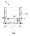
- the nozzle 18 has a recess 22 (see FIG. 2 ) into which a sealing portion 24 can be inserted.
- the sealing portion 24 in this case comprises a material which is selected so that the sealing portion 24 which is welded to the nozzle 18. Consequently, a second weld 25 is present.
- the sealing portion 24 has a recess 26 into which a corresponding projection 28 of a Wandungsablvess 30 of the pressure sensor 12 can be introduced.
- the sealing portion 24 may be connected to the wall portion 30 in any suitable manner.
- the nozzle 18, the sealing portion 24 and the wall portion 30 of the pressure sensor 12 are each formed annularly.
- the ceramic membrane 14 is made of, for example, aluminum oxide (Al 2 O 3 ), while the sealing portion 24 is made of titanium. Both materials have a similar coefficient of thermal expansion, so that keep thermoelectric voltages due to temperature fluctuations within narrow limits and thus caused damage largely avoided. In addition, temperature-related influences on the measurement result are reduced.
- the sealing portion 24 is shrunk onto the ceramic membrane 14.
- the sealing portion 24 is heated so far, so that its inner diameter d i increased so that the ceramic membrane 14 can be introduced into the sealing portion 24 and the sealing portion 24 surrounds the ceramic membrane 14.
- the sealing portion 24 is cooled, so that the inner diameter d i decreases again to the original degree, so that a gap-free connection is formed.
- Either the sealing portion 24 or the ceramic membrane 14 or both have a coating 32 of a ductile material, for example of parylene, on the surfaces coming into contact during shrinking.
- the coating 32 of ductile material can compensate for unevenness or other inaccuracies in the contacting surfaces, so that the coating 32 acts as a leveling and sealing layer.
- Level measurement unit 12 pressure sensor 14 ceramic membrane 16 connector 18
- Support 20 flange 21 first weld 22 recess 24 sealing portion 25 second weld 26 recess 28 head
Abstract
Die vorliegende Erfindung betrifft einen Dichtabschnitt für eine Füllstandsmesseinheit (10) zum Bestimmen des Füllstands in einem Behältnis, wobei die Füllstandsmesseinheit (10) einen Drucksensor (12) zum Bestimmen des Drucks im Behältnis, wobei der Drucksensor (12) eine druckempfindliche Keramikmembran (14) aufweist, und ein Anschlussstück (16) umfasst, mit dem die Füllstandsmesseinheit (10) am Behältnis anschließbar ist und das den Drucksensor (12) umschließt, wobei der Dichtabschnitt (24) ein Material umfasst, welches so gewählt ist, dass der Dichtabschnitt (24) auf die Keramikmembran (14) aufschrumpfbar ist.The present invention relates to a sealing section for a filling level measuring unit (10) for determining the filling level in a container, wherein the filling level measuring unit (10) comprises a pressure sensor (12) for determining the pressure in the container, wherein the pressure sensor (12) comprises a pressure-sensitive ceramic membrane (14). and a connecting piece (16) with which the filling level measuring unit (10) can be connected to the container and which encloses the pressure sensor (12), wherein the sealing portion (24) comprises a material which is chosen so that the sealing portion (24 ) is shrinkable on the ceramic membrane (14).
Description
Die vorliegende Erfindung betrifft einen Dichtabschnitt für eine Füllstandsmesseinheit zum Bestimmen des Füllstands in einem Behältnis, wobei die Füllstandsmesseinheit einen Drucksensor zum Bestimmen des Drucks im Behältnis und ein Anschlussstück umfasst, mit dem die Füllstandsmesseinheit am Behältnis anschließbar ist und das den Drucksensor umschließt, wobei der Drucksensor eine druckempfindliche Keramikmembran aufweist. Ferner betrifft die Erfindung das Anschlussstück und die Füllstandsmesseinheit selbst sowie ein Verfahren zum spaltfreien Verbinden eines Dichtabschnitts mit einer druckempfindlichen Keramikmembran eines Drucksensors und einem Anschlussstück einer Füllstandsmesseinheit zum Bestimmen des Füllstands in einem Behältnis.The present invention relates to a sealing portion for a level measuring unit for determining the level in a container, wherein the level measuring unit comprises a pressure sensor for determining the pressure in the container and a connector with which the level measuring unit is connectable to the container and which encloses the pressure sensor, wherein the pressure sensor having a pressure-sensitive ceramic membrane. Furthermore, the invention relates to the connection piece and the level measuring unit itself and a method for gap-free connection of a sealing portion with a pressure-sensitive ceramic membrane of a pressure sensor and a connection piece of a level measuring unit for determining the level in a container.
Füllstandsmesseinheiten werden in ganz unterschiedlichen Bereichen der Technik eingesetzt. In der Verfahrenstechnik wird unter einem Fed-Batch eine Betriebsweise eines Reaktors verstanden, bei der eine bestimmte Substanz einem im Innenraum des Reaktors befindlichen Reaktionsgemisch zugegeben wird. Dabei ist es üblich, das Reaktionsgemisch zu rühren. Um eine ausreichende Durchmischung gewährleisten zu können, darf das Volumen im Reaktor ein bestimmtes Maß nicht überschreiten. Insbesondere soll verhindert werden, dass das Reaktionsgemisch mit der oberen Wandung des Reaktors in Berührung kommt. Folglich ist es wichtig, immer eine aktuelle Information über den momentanen Füllstand zu bekommen, so dass die Zugabe der Substanz rechtzeitig unterbrochen werden kann.Level measuring units are used in very different areas of technology. In process engineering, a fed batch is understood as meaning a mode of operation of a reactor in which a specific substance is added to a reaction mixture present in the interior of the reactor. It is customary to stir the reaction mixture. To ensure adequate mixing, the volume in the reactor must not exceed a certain level. In particular, it should be prevented that the reaction mixture comes into contact with the upper wall of the reactor. Consequently, it is important to always get up-to-date information about the current level, so that the addition of the substance can be interrupted in time.
Es gibt aber auch Anwendungen, in denen ein gewisser Füllstand nicht unterschritten werden soll, beispielsweise in Futtersilos, wo das Unterschreiten eines Füllstands ein Hinweis darauf ist, dass der Futtervorrat demnächst verbraucht ist und das Futtersilo wieder aufgefüllt werden sollte.But there are also applications in which a certain level should not fall below, for example in feed silos, where falling below a level is an indication that the feed supply is soon consumed and the feed silo should be replenished.
Füllstandsmesseinheiten ermöglichen die automatische Kontrolle der Füllstände und sind daher integraler Bestandteil von Prozesssteuerungssystemen. Die Füllstandsmesseinheiten können an den jeweiligen Aggregatszustand der Substanz, deren Füllstand bestimmt werden soll, angepasst werden, so dass der Füllstand von festen, flüssigen oder gasförmigen Substanzen bestimmbar ist. Die Füllstandsmesseinheiten umfassen Anschlussstücke, mit denen sie in Öffnungen der jeweiligen Behältnisse, in denen sich die Substanz, deren Füllstand bestimmt werden soll, befindet, eingesetzt und an den Wandungen der Behältnisse befestigt werden.Level measuring units enable automatic level control and are therefore an integral part of Process control systems. The level measuring units can be adapted to the respective state of aggregation of the substance whose level is to be determined, so that the level of solid, liquid or gaseous substances can be determined. The level measuring units comprise connecting pieces with which they are inserted into openings of the respective containers in which the substance whose level is to be determined is used and fastened to the walls of the containers.
Eine bekannte Möglichkeit, den Füllstand eines Füllguts in einem Behältnis zu bestimmen, ist die Bestimmung des vom Füllgut erzeugten hydrostatischen Drucks. Hierzu sind Füllstandsmesseinheiten bekannt, die einen Drucksensor mit einer Membran aus Edelstahl aufweisen. Die Membran bei derartigen Drucksensoren besteht üblicherweise aus gewelltem Edelstahl, die auf Unterschiede im hydrostatischen infolge des sich ändernden Füllstands reagiert. Der Drucksensor und die Membran sind dabei so eingerichtet, dass der sich ändernde hydrostatische Druck eine Änderung im elektrischen Widerstand eines durch die Edelstahlmembran fließenden Stroms bewirkt, aus der auf den Füllstand geschlossen werden kann. Die Membran aus Edelstahl kann dabei spaltfrei mit der Wandung des Drucksensors verschweißt werden. Eine spaltfreie Abdichtung ist insofern von besonderer Wichtigkeit, als dass die Substanz, deren Füllstand ermittelt werden soll, nicht unkontrolliert aus dem Behältnis austreten und in den Drucksensor eindringen darf.One known way to determine the level of a product in a container, is the determination of the hydrostatic pressure generated by the product. For this purpose, level measuring units are known which have a pressure sensor with a membrane made of stainless steel. The membrane in such pressure sensors is usually made of corrugated stainless steel, which responds to differences in the hydrostatic due to the changing level. The pressure sensor and the membrane are arranged so that the changing hydrostatic pressure causes a change in the electrical resistance of a current flowing through the stainless steel membrane, from which can be closed to the level. The membrane made of stainless steel can be welded gap-free with the wall of the pressure sensor. A gap-free seal is of particular importance in that the substance whose level is to be determined, not uncontrollably escape from the container and may penetrate into the pressure sensor.
Die gewellte Membran weist eine sehr geringe Dicke von ca. 50 µm auf, die somit sehr empfindlich gegenüber Verschleiß ist. Darüber hinaus wird bei derartigen Drucksensoren häufig eine Druckmittler-Flüssigkeit eingesetzt, die aber bei bestimmten Anwendungen nicht immer zugelassen ist, beispielsweise im Lebensmittel- und Pharmabereich. Zudem umfassen die Druckmittler-Flüssigkeiten häufig sogenannte Lack-benetzungsstörende Substanzen (LABS) wie Silikon, die in Lackieranlagen nicht eingesetzt werden dürfen.The corrugated membrane has a very small thickness of about 50 microns, which is thus very sensitive to wear. In addition, in such pressure sensors often a diaphragm seal liquid is used, which is not always approved in certain applications, for example in the food and pharmaceutical industries. In addition, the sealant fluids often include so-called paint wetting impinging substances (LABS) such as silicone, which must not be used in paint shops.
Eine weitere Ausführungsform der bekannten Füllstandsmesseinheiten weist Drucksensoren mit einer Membran aus Keramik auf. Hierbei bewirkt der hydrostatische Druck des Füllgutes oder der Prozessdruck im Behältnis eine Auslenkung der Keramikmembran. Bei sich ändernden hydrostatischen Drücken stellt sich eine Kapazitätsänderung ein, aus der auf den Füllstand geschlossen werden kann. Drucksensoren mit einer Keramikmembran werden immer dann eingesetzt, wenn die Härte und Robustheit der Keramikmembran einen entscheidenden Vorteil bringt, insbesondere bei einem sehr korrosiven und abrasivem Füllgut. Zudem können die Keramikmembranen sehr flach ausgeführt sein, so dass sie frontbündig am Drucksensor angeordnet werden können und sich leicht reinigen lassen.Another embodiment of the known level measuring units has pressure sensors with a membrane made of ceramic. This causes the hydrostatic pressure of the filling material or the process pressure in the container a deflection of the ceramic membrane. With changing hydrostatic pressures, a change in capacity occurs, from which it is possible to deduce the level. Pressure sensors with a ceramic membrane are always used when the hardness and robustness of the ceramic membrane brings a decisive advantage, especially with a very corrosive and abrasive filling material. In addition, the ceramic membranes can be made very flat, so that they can be flush mounted on the pressure sensor and can be easily cleaned.
Nachteilig bei Drucksensoren mit Keramikmembranen ist jedoch, dass sie sich nicht wie die Drucksensoren aus Edelstahl mit der Wandung des Drucksensors verschweißen lassen. Folglich muss die Abdichtung unter Verwendung von Elastomeren erfolgen, was aber einige Nachteile mit sich bringt. Sinkt die Temperatur im Behältnis oder in der Umgebung des Behältnisses unter einen bestimmten Wert, so verringert sich die Elastizität der Elastomere so weit, dass keine spaltfreie Abdichtung mehr möglich ist, was insbesondere dann ein Problem darstellt, wenn Schwingungen im Behältnis auftreten. Ferner ist der Einsatz von Elastomeren in der Pharma- und Lebensmittelindustrie nur bedingt möglich, da es nicht ausgeschlossen werden kann, dass Teile der Elastomere in das jeweilige im Behältnis befindliche Produkt migrieren. Darüber hinaus müssen die Elastomere regelmäßig ausgetauscht werden, so dass sich der Betrieb der betreffenden Füllstandsmesseinheit verteuert.A disadvantage of pressure sensors with ceramic membranes, however, is that they can not be welded like the pressure sensors made of stainless steel with the wall of the pressure sensor. Consequently, the sealing must be done using elastomers, but with some disadvantages. If the temperature in the container or in the vicinity of the container falls below a certain value, the elasticity of the elastomers is reduced so much that no gap-free sealing is possible, which is a particular problem when vibrations occur in the container. Furthermore, the use of elastomers in the pharmaceutical and food industries is only possible to a limited extent, since it can not be ruled out that parts of the elastomers migrate into the respective product in the container. In addition, the elastomers must be replaced regularly, so that the operation of the relevant level measuring unit more expensive.
Es ist bekannt, die Keramikmembranen mit Metallen zu verlöten, die einen ähnlichen Temperaturausdehnungskoeffizienten wie die für die Membran verwendete Keramik aufweisen. Allerdings haben diese Metalle den Nachteil, dass sie nur eine begrenzte Korrosionsbeständigkeit aufweisen und daher nur für bestimmte Anwendungen geeignet sind.It is known to solder the ceramic membranes with metals having a similar coefficient of thermal expansion as the ceramic used for the membrane. However, these metals have the disadvantage that they have only a limited corrosion resistance and therefore are only suitable for certain applications.
Aufgabe der vorliegenden Erfindung ist es daher, einen Dichtabschnitt anzugeben, mit dem Drucksensoren mit Keramikmembranen spaltfrei gegenüber den Anschlussstücken spaltfrei ohne die oben genannten Nachteile abgedichtet insbesondere ohne den Einsatz von Elastomeren werden können.Object of the present invention is therefore to provide a sealing portion, with the pressure sensors with ceramic membranes gap-free with respect to the fittings gap-free without the above-mentioned disadvantages sealed in particular without the use of elastomers can be.
Gelöst wird die Aufgabe dadurch, dass der Dichtabschnitt ein Material umfasst, welches so gewählt ist, dass der Dichtabschnitt auf die Keramikmembran aufschrumpfbar ist. Durch das Aufschrumpfen des Dichtabschnitts lässt sich auf eine relativ einfache Weise eine zuverlässige spaltfreie Verbindung zwischen der Keramikmembran und dem Dichtabschnitt bereitstellen. Dabei wird das Material des Dichtabschnitts so gewählt, dass es sich bei Erwärmung ausdehnt und bei Abkühlung auf die üblicherweise im Behältnis oder in der Umgebung des Behältnisses herrschenden Bedingungen zusammenzieht. Es ist folglich nicht notwendig, einen Stoffschluss mit der Keramikmembran herzustellen, so dass man bei der Materialwahl deutlich freier ist als es bei den im Stand der Technik bekannten Lötverbindungen zwischen Keramikmembran und Dichtabschnitt der Fall ist. Insbesondere kann der Dichtabschnitt aus einem Material gefertigt werden, welches korrosionsbeständig ist. Auch ist es auf diese Weise möglich, auf die Verwendung von Elastomeren zu verzichten und ein Material auszuwählen, welches nicht in die Substanzen migriert, die sich im Behältnis befinden. Es wird eine spaltfreie und diffusionsdichte Verbindung zwischen dem Dichtabschnitt und der Keramikmembran des Drucksensors geschaffen, ohne dass Dichtungen kontrolliert und gegebenenfalls ausgetauscht werden müssten. Darüber hinaus kann auf eine Druckmittler-Flüssigkeit verzichtet werden, was insofern besonders vorteilhaft ist, als dass ein "trockener" Drucksensor bereitgestellt wird, so dass die Lage des Drucksensors keinen oder nahezu keinen Einfluss auf die Messergebnisse hat, was bei Drucksensoren mit Druckmittler-Flüssigkeit nicht der Fall ist. Weiterhin ist es ausgeschlossen, dass die Druckmittler-Flüssigkeit in Kontakt mit der im Behältnis befindlichen Substanz kommen kann, so dass der erfindungsgemäße Drucksensor auch in Anwendungen eingesetzt werden kann, die LABSfrei sein müssen, beispielsweise im Pharma- und Lebensmittelbereich sowie in Lackieranlagen. Zudem sind Keramikmembranen deutlich robuster als Edelstahlmembranen, abrasionsfest und lassen sich frontbündig im Drucksensor anordnen sowie flach und eben ausführen, so dass sie sich insbesondere im Vergleich zu einer gewellten Edelstahlmembran leichter reinigen lassen.The object is achieved in that the sealing portion comprises a material which is chosen so that the sealing portion is aufschrumpfbar on the ceramic membrane. By shrinking the sealing portion can be provided in a relatively simple manner, a reliable gap-free connection between the ceramic membrane and the sealing portion. In this case, the material of the sealing portion is selected so that it expands when heated and contracts on cooling to the conditions prevailing in the container or in the environment of the container conditions. It is therefore not necessary to produce a material bond with the ceramic membrane, so that one is significantly freer in the choice of material than is the case in the known in the art solder joints between the ceramic membrane and sealing section. In particular, the sealing portion can be made of a material which is corrosion resistant. Also, it is possible in this way to dispense with the use of elastomers and to select a material that does not migrate into the substances that are in the container. It creates a gap-free and diffusion-tight connection between the sealing portion and the ceramic membrane of the pressure sensor without seals must be controlled and replaced if necessary. In addition, can be dispensed with a diaphragm seal liquid, which is particularly advantageous in that a "dry" pressure sensor is provided so that the position of the pressure sensor has no or almost no influence on the measurement results, which in pressure sensors with diaphragm seal fluid not the case. Furthermore, it is impossible for the pressure-mediator liquid to come into contact with the substance in the container, so that the pressure sensor according to the invention can also be used in applications which have to be LAB-free, for example in the pharmaceutical and food sectors and in paint shops. In addition, ceramic membranes are much more robust than stainless steel membranes, resistant to abrasion, and can be flush-mounted in the pressure sensor and flat and flat so that they are easier to clean, especially when compared to a corrugated stainless steel membrane.
Vorzugsweise wird das Material des Dichtabschnitts so gewählt, dass es mit dem Anschlussstück mittels eines Stoffschlusses verbindbar ist. Mit einem Stoffschluss wird eine unlösbare Verbindung geschaffen, die in hohem Maße spaltfrei und damit diffusionsdicht ist. Dabei wird der Stoffschluss vorzugsweise mittels eines Schmelzverfahrens und insbesondere mittels eines Schweißverfahrens bereitgestellt. Diese Verfahren lassen sich heutzutage gut automatisieren und stellen sicher, dass eine robuste, spaltfreie und diffusionsdichte Verbindung zwischen dem Dichtabschnitt und dem Anschlussstück geschaffen wird. Zudem lässt sich eine große Anzahl von Materialien mittels eines Schmelzverfahrens zum Bereitstellen eines Stoffschlusses bearbeiten, so dass hierdurch die Auswahl der geeigneten Materialien unwesentlich eingeschränkt wird.Preferably, the material of the sealing portion is selected so that it is connectable to the connector by means of a fabric bond. With a fabric bond, a permanent bond is created, which is highly gap-free and thus diffusion-tight. In this case, the material bond is preferably provided by means of a melting process and in particular by means of a welding process. These methods can be well automated today and ensure that a robust, gap-free and diffusion-tight connection between the sealing portion and the connector is created. In addition, a large number of materials can be processed by means of a melting process to provide a material bond, so that the selection of suitable materials is insignificantly limited.
In einer vorteilhaften Ausgestaltung des erfindungsgemäßen Dichtabschnitts weist das Material einen Wärmeausdehnungskoeffizienten auf, welcher im Wesentlichen gleich dem der Keramikmembran ist. Hierdurch wird sichergestellt, dass über einen sehr großen Temperaturbereich keine Thermospannungen auftreten, die zu einer Spaltbildung zwischen dem Dichtabschnitt und dem Drucksensor führen und somit die Abdichtung gefährden könnten. So eignet sich diese Ausgestaltung insbesondere für Anwendungen, bei denen große Temperaturschwankungen auftreten. Der Fachmann weiß, welche Abweichungen in den Werten der Wärmeausdehnungskoeffizienten der für den Dichtabschnitt und die Keramikmembran verwendeten Materialien für welchen Temperaturbereich akzeptiert werden können.In an advantageous embodiment of the sealing section according to the invention, the material has a thermal expansion coefficient which is substantially equal to that of the ceramic membrane. This ensures that over a very large temperature range no thermal stresses occur, which lead to a gap formation between the sealing portion and the pressure sensor and thus could endanger the seal. Thus, this embodiment is particularly suitable for applications in which large temperature fluctuations occur. The person skilled in the art knows which deviations in the values of the thermal expansion coefficients of the materials used for the sealing section and the ceramic membrane can be accepted for which temperature range.
Vorzugsweise ist das Material Titan. Titan weist einen Wärmeausdehnungskoeffizient auf, der denjenigen von üblicherweise verwendeten Materialien für die Keramikmembran wie Aluminiumoxid (Al2O3) sehr ähnlich ist. Zudem lässt sich Titan unter einer Schutzgasatmosphäre gut schweißen und ist temperatur- und korrosionsbeständig.Preferably, the material is titanium. Titanium has a coefficient of thermal expansion very similar to that of commonly used ceramic membrane materials such as alumina (Al 2 O 3 ). In addition, titanium can be welded well under a protective gas atmosphere and is temperature and corrosion resistant.
In einer besonders bevorzugten Ausgestaltung weist der Dichtabschnitt eine Beschichtung aus einem duktilen Material auf. Beispielsweise können als duktiles Material Parylene verwendet werden. Parylene sind hydrophobe, chemisch resistente Kunststoffe mit guter Barrierenwirkung gegenüber anorganischen und organischen Medien, starken Säuren, Laugen, Gasen und Wasserdampf. Zudem sind sie biostabil und biokompatibel. Wird der Dichtabschnitt auf die Wandung des Drucksensors aufgeschrumpft, können sich infolge von Fertigungsungenauigkeiten im Verlauf der sich kontaktierenden Flächen Spannungserhöhungen oder Spalte ausbilden. Die Beschichtung aus einem duktilen Material gleicht die Fertigungsungenauigkeiten aus und verhindert somit die Ausbildung von Spannungserhöhungen in der Wandung des Drucksensors oder im Dichtabschnitt. Infolge davon wird die Gefahr einer Rissbildung oder Deformation verringert. Zudem füllt das duktile Material eventuell entstehende Spalte aus, so dass die Dichtigkeit erhöht wird. Insofern wirkt die Beschichtung aus dem duktilen Material wie eine Dichtschicht.In a particularly preferred embodiment, the sealing portion has a coating of a ductile material. For example, can be used as a ductile material Parylene. Parylene are hydrophobic, chemically resistant plastics with good barrier effect against inorganic and organic media, strong acids, alkalis, gases and water vapor. In addition, they are biostable and biocompatible. If the sealing section is shrunk onto the wall of the pressure sensor, as a result of production inaccuracies, voltage increases or gaps may form in the course of the contacting surfaces. The coating of a ductile material compensates for the manufacturing inaccuracies and thus prevents the formation of voltage increases in the wall of the pressure sensor or in the sealing section. As a result, the risk of cracking or deformation is reduced. In addition, the ductile material fills any resulting gaps, so that the tightness is increased. In this respect, the coating of the ductile material acts like a sealing layer.
Vorzugsweise ist der Dichtabschnitt ringförmig ausgestaltet. Dabei umschließt der Dichtabschnitt den Drucksensor, der vorzugsweise eine zylindrische Form hat. Hierdurch wird das Aufschrumpfen erleichtert, da der Dichtabschnitt bezüglich der gemeinsamen Achse nicht in einem gewissen Winkel auf den Drucksensor aufgeschrumpft werden muss. Aufgrund der rotationssymmetrischen Form lassen sich sowohl die Wandung des Drucksensors als auch der Dichtabschnitt einfach und kostengünstig herstellen.Preferably, the sealing portion is configured annular. In this case, the sealing portion surrounds the pressure sensor, which preferably has a cylindrical shape. As a result, the shrinking is facilitated because the sealing portion with respect to the common axis does not have to be shrunk onto the pressure sensor at a certain angle. Due to the rotationally symmetrical shape, both the wall of the pressure sensor and the sealing section can be produced simply and inexpensively.
Ein weiterer Aspekt der Erfindung betrifft ein Anschlussstück zum Anschließen einer Füllstandsmesseinheit an einem Behältnis, wobei die Füllstandsmesseinheit einen Drucksensor zum Bestimmen des Drucks im Behältnis, und einen Dichtabschnitt zum Abdichten der Füllstandsmesseinheit umfasst, wobei das Anschlussstück mittels eines Stoffschlusses mit dem Dichtabschnitt verbindbar ist und der Drucksensor eine druckempfindliche Keramikmembran aufweist. Mit einem Stoffschluss lässt sich eine spaltfreie, diffusionsdichte und dauerfeste Verbindung zwischen dem Dichtabschnitt und dem Anschlussstück bereitstellen, die in hohem Maße dicht ist.Another aspect of the invention relates to a connecting piece for connecting a level measuring unit to a container, wherein the level measuring unit comprises a pressure sensor for determining the pressure in the container, and a sealing portion for sealing the level measuring unit, wherein the connecting piece is connected by means of a material connection with the sealing portion and the Pressure sensor has a pressure-sensitive ceramic membrane. With a material connection can be a gap-free, diffusion-tight and durable connection between the sealing portion and the fitting provide that is highly dense.
Die Aufgabe wird ferner durch eine Füllstandsmesseinheit zum Bestimmen des Füllstands in einem Behältnis gelöst, wobei die Füllstandsmesseinheit einen Drucksensor zum Bestimmen des Drucks im Behältnis und ein Anschlussstück umfasst, mit dem die Füllstandsmesseinheit am Behältnis anschließbar ist und das den Drucksensor umschließt, wobei der Drucksensor eine druckempfindliche Keramikmembran und die Füllstandsmesseinheit ein Dichtabschnitt nach einem der vorherigen Ausführungsbeispiele aufweist. Die Vorteile und technischen Effekte, die mit der erfindungsgemäßen Füllstandsmesseinheit erzielt werden, entsprechen denjenigen, die für den erfindungsgemäßen Dichtabschnitt und für das erfindungsgemäße Anschlussstück beschrieben worden sind. Insbesondere kann der Dichtabschnitt auf die Keramikmembran aufgeschrumpft und mit dem Anschlussstück mittels eines Stoffschlusses verbunden werden, so dass der Drucksensor spaltfrei und ohne Verwendung von Elastomeren gegenüber dem Anschlussstück auf einfache und kostengünstige Weise diffusionsdicht abgedichtet werden kann.The object is further achieved by a level measuring unit for determining the level in a container, wherein the level measuring unit comprises a pressure sensor for determining the pressure in the container and a connecting piece, with which the Level measuring unit can be connected to the container and which encloses the pressure sensor, wherein the pressure sensor comprises a pressure-sensitive ceramic membrane and the level measuring unit has a sealing portion according to one of the previous embodiments. The advantages and technical effects which are achieved with the level measuring unit according to the invention, correspond to those which have been described for the sealing portion according to the invention and for the connector according to the invention. In particular, the sealing portion can be shrunk onto the ceramic membrane and connected to the connection piece by means of a material connection, so that the pressure sensor can be sealed diffusion-tight and without the use of elastomers with respect to the connection piece in a simple and cost-effective manner.
Vorzugsweise weist die Keramikmembran eine Beschichtung aus einem duktilen Material auf. Wird der Dichtabschnitt auf die Keramikmembran des Drucksensors aufgeschrumpft, können sich infolge von Fertigungsungenauigkeiten im Verlauf der sich kontaktierenden Flächen Spannungserhöhungen oder Spalte ausbilden. Die Beschichtung aus einem duktilen Material gleicht die Fertigungsungenauigkeiten aus und verhindert somit die Ausbildung von Spannungserhöhungen in der Keramikmembran oder im Dichtabschnitt. Infolge davon wird die Gefahr einer ungewollten Deformation oder gar Zerstörung der Keramikmembran verringert. Zudem gleicht das duktile Material eventuell entstehende Spalte aus, so dass die Dichtigkeit erhöht wird. Weiterhin kann die Beschichtung die Übertragung von Schwingungen vom Behältnis auf die Keramikmembran dämpfen, so dass der Einfluss der Schwingungen auf das Messergebnis verringert wird.Preferably, the ceramic membrane has a coating of a ductile material. If the sealing section is shrunk onto the ceramic membrane of the pressure sensor, as a result of production inaccuracies, voltage increases or gaps may form in the course of the contacting surfaces. The coating of a ductile material compensates for manufacturing inaccuracies and thus prevents the formation of voltage increases in the ceramic membrane or in the sealing section. As a result, the risk of unwanted deformation or even destruction of the ceramic membrane is reduced. In addition, the ductile material compensates for any resulting gaps, so that the tightness is increased. Furthermore, the coating can dampen the transmission of vibrations from the container to the ceramic membrane, so that the influence of the vibrations on the measurement result is reduced.
In einer bevorzugten Ausgestaltung ist das Anschlussstück der Füllstandsmesseinheit nach einem der diesbezüglich diskutierten Ausführungen ausgebildet. Die Vorteile und technischen Effekte, die mit dieser Ausgestaltung der erfindungsgemäßen Füllstandsmesseinheit erzielt werden, entsprechen denjenigen, die für das erfindungsgemäße Anschlussstück beschrieben worden sind.In a preferred embodiment, the connection piece of the filling level measuring unit is designed according to one of the embodiments discussed in this regard. The advantages and technical effects which are achieved with this embodiment of the level measuring unit according to the invention, correspond to those which have been described for the connector according to the invention.
Vorzugsweise umfasst keramische Material Aluminiumoxid (Al2O3) oder besteht hieraus. Aluminiumoxid ist günstig in der Anschaffung und lässt sich auf einfache Weise zu einem keramischen Material weiterverarbeiten.Preferably, ceramic material comprises or consists of alumina (Al 2 O 3 ). Aluminum oxide is inexpensive to buy and can be easily processed into a ceramic material.
Ein weiterer Aspekt der Erfindung betrifft ein Verfahren zum spaltfreien Verbinden eines Dichtabschnitts mit einer druckempfindlichen Keramikmembran eines Drucksensors und einem Anschlussstück einer Füllstandsmesseinheit zum Bestimmen des Füllstands in einem Behältnis, umfassend folgende Schritte:
- Erwärmen des Dichtabschnitts auf eine vorgebbare Temperatur,
- Einbringen der Keramikmembran in den Dichtabschnitt und Aufschrumpfen des Dichtabschnitts auf die Wandung, und
- stoffschlüssiges Verbinden des Dichtabschnitts mit dem Anschlussstück.
- Heating the sealing section to a predeterminable temperature,
- Introducing the ceramic membrane into the sealing section and shrinking the sealing section onto the wall, and
- integral connection of the sealing portion with the connector.
Mit dem erfindungsgemäßen Verfahren kann auf einfache Weise eine zuverlässige Abdichtung des Dichtabschnitts gegenüber der Keramikmembran und gegenüber dem Anschlussstück bereitgestellt werden. Es kann auf die Verwendung von Elastomeren verzichtet werden, so dass eine spaltfreie und diffusionsdichte Verbindung über einen großen Temperaturbereich geschaffen werden kann, ohne dass die Gefahr besteht, dass Bestandteile in die Substanz, die sich im Behältnis befindet, migriert. Im Übrigen entsprechen die Vorteile und technischen Effekte des erfindungsgemäßen Verfahrens denjenigen, die für den erfindungsgemäßen Dichtabschnitt, das erfindungsgemäße Anschlussstück und die erfindungsgemäße Füllstandsmesseinheit erläutert worden sind.With the method according to the invention, a reliable sealing of the sealing section with respect to the ceramic membrane and with respect to the connecting piece can be provided in a simple manner. It may be dispensed with the use of elastomers, so that a gap-free and diffusion-tight connection over a wide temperature range can be created without the risk that constituents in the substance, which is in the container migrated. Incidentally, the advantages and technical effects of the method according to the invention correspond to those which have been explained for the sealing section according to the invention, the connecting piece according to the invention and the fill level measuring unit according to the invention.
Die Erfindung wird im Folgenden anhand eines bevorzugten Ausführungsbeispiels unter Bezugnahme auf die anhängende Zeichnung im Detail erläutert. Es zeigen
- Figur 1
- eine Schnittzeichnung eines Ausführungsbeispiels der erfindungsgemäßen Füllstandsmesseinheit, und
- Figur 2
- einen vergrößerten, nicht maßstäblichen Ausschnitt aus
Figur 1 im Bereich des Kreises A, wobei nur die erfindungsrelevanten Teile berücksichtigt sind.
- FIG. 1
- a sectional drawing of an embodiment of the filling level measuring unit according to the invention, and
- FIG. 2
- an enlarged, not to scale section
FIG. 1 in the region of the circle A, whereby only the relevant parts are considered.
Die folgende Figurenbeschreibung bezieht sich sowohl auf
Die
The
Der Stutzen 18 weist eine Ausnehmung 22 auf (siehe
Der Dichtabschnitt 24 ist auf die Keramikmembran 14 aufgeschrumpft. Hierzu wird der Dichtabschnitt 24 so weit erwärmt, so dass sich sein Innendurchmesser di so weit vergrößert, dass die Keramikmembran 14 in den Dichtabschnitt 24 einbringbar ist und der Dichtabschnitt 24 die Keramikmembran 14 umschließt. Die Temperatur, auf die der Dichtabschnitt 24 hierbei erwärmt werden muss, kann der Fachmann problemlos ermitteln. Anschließend wird der Dichtabschnitt 24 abgekühlt, so dass sich der Innendurchmesser di wieder auf das ursprüngliche Maß verringert, so dass eine spaltfreie Verbindung entsteht. Entweder der Dichtabschnitt 24 oder die Keramikmembran 14 oder beide weisen auf den beim Aufschrumpfen in Kontakt kommenden Flächen eine Beschichtung 32 aus einem duktilen Material, beispielsweise aus Parylene, auf. Beim Aufschrumpfen des Dichtabschnitts 24 auf die Keramikmembran 14 kann die Beschichtung 32 aus duktilem Material Unebenheiten oder andere Ungenauigkeiten der sich kontaktierenden Flächen ausgleichen, so dass die Beschichtung 32 als Ausgleichs- und Dichtschicht wirkt.
Claims (13)
dadurch gekennzeichnet, dass das Material des Dichtabschnitts (24) mit dem Anschlussstück (16) mittels eines Stoffschlusses verbindbar ist.Sealing section according to claim 1,
characterized in that the material of the sealing portion (24) with the connecting piece (16) is connectable by means of a fabric closure.
dadurch gekennzeichnet, dass der Stoffschluss mittels eines Schmelzverfahrens und insbesondere mittels eines Schweißverfahrens bereitgestellt wird.Sealing section according to claim 2,
characterized in that the material bond is provided by means of a melting process and in particular by means of a welding process.
dass das Material einen Wärmeausdehnungskoeffizienten aufweist, welcher im Wesentlichen gleich dem der Keramikmembran (14) ist.Sealing section according to one of the preceding claims,
the material has a thermal expansion coefficient which is substantially equal to that of the ceramic membrane (14).
dadurch gekennzeichnet, dass das Material Titan ist.Sealing section according to one of the preceding claims,
characterized in that the material is titanium.
dadurch gekennzeichnet, dass der Dichtabschnitt (24) eine Beschichtung (32) aus einem duktilen Material aufweist.Sealing section according to one of the preceding claims,
characterized in that the sealing portion (24) comprises a coating (32) of a ductile material.
dadurch gekennzeichnet, dass der Dichtabschnitt (24) ringförmig ausgebildet ist.Sealing section according to one of the preceding claims,
characterized in that the sealing portion (24) is annular.
dadurch gekennzeichnet, dass die Wandung des Drucksensors (12) eine Beschichtung (32) aus einem duktilen Material aufweist.Level measuring unit (10) according to claim 9,
characterized in that the wall of the pressure sensor (12) has a coating (32) made of a ductile material.
dadurch gekennzeichnet, dass das Anschlussstück (16) nach einem der Ansprüche 8 oder 9 ausgebildet ist.Level measuring unit (10) according to claim 10,
characterized in that the connecting piece (16) according to one of claims 8 or 9 is formed.
dadurch gekennzeichnet, dass die Keramikmembran (14) Aluminiumoxid (Al2O3) umfasst oder hieraus besteht.Level measuring unit (10) according to one of claims 10 or 11,
characterized in that the ceramic membrane (14) comprises or consists of alumina (Al 2 O 3 ).
Priority Applications (1)
| Application Number | Priority Date | Filing Date | Title |
|---|---|---|---|
| EP13165011.1A EP2796838A1 (en) | 2013-04-23 | 2013-04-23 | Seal section for a fill level measuring unit for determining the fill level in a container |
Applications Claiming Priority (1)
| Application Number | Priority Date | Filing Date | Title |
|---|---|---|---|
| EP13165011.1A EP2796838A1 (en) | 2013-04-23 | 2013-04-23 | Seal section for a fill level measuring unit for determining the fill level in a container |
Publications (1)
| Publication Number | Publication Date |
|---|---|
| EP2796838A1 true EP2796838A1 (en) | 2014-10-29 |
Family
ID=48182767
Family Applications (1)
| Application Number | Title | Priority Date | Filing Date |
|---|---|---|---|
| EP13165011.1A Withdrawn EP2796838A1 (en) | 2013-04-23 | 2013-04-23 | Seal section for a fill level measuring unit for determining the fill level in a container |
Country Status (1)
| Country | Link |
|---|---|
| EP (1) | EP2796838A1 (en) |
Cited By (2)
| Publication number | Priority date | Publication date | Assignee | Title |
|---|---|---|---|---|
| CN106595804A (en) * | 2017-02-07 | 2017-04-26 | 浙江众邦机电科技有限公司 | Industrial sewing machine and fuel quantity detection system applied to same, and ceramic pressure sensing apparatus |
| CN114323193A (en) * | 2022-03-14 | 2022-04-12 | 山东省鲁南地质工程勘察院(山东省地质矿产勘查开发局第二地质大队) | Hydrogeological drilling water level monitoring device and method based on radio |
Citations (5)
| Publication number | Priority date | Publication date | Assignee | Title |
|---|---|---|---|---|
| US4462258A (en) * | 1982-03-18 | 1984-07-31 | King Engineering Corporation | Pressure sensor and method of producing same |
| US4898035A (en) * | 1988-01-16 | 1990-02-06 | Ngk Insulators, Ltd. | Pressure sensor having sealing member for sealing housing interior with respect to external space |
| US20050145035A1 (en) * | 2003-04-24 | 2005-07-07 | Thomas Kopp | Sensor, specifically a pressure sensor to be fastened to a receptacle |
| US20100038012A1 (en) * | 2006-07-28 | 2010-02-18 | The Regents Of The University Of California | Joined concentric tubes |
| US20120160025A1 (en) * | 2010-12-22 | 2012-06-28 | Vega Grieshaber Kg | Filling-level measuring device |
-
2013
- 2013-04-23 EP EP13165011.1A patent/EP2796838A1/en not_active Withdrawn
Patent Citations (5)
| Publication number | Priority date | Publication date | Assignee | Title |
|---|---|---|---|---|
| US4462258A (en) * | 1982-03-18 | 1984-07-31 | King Engineering Corporation | Pressure sensor and method of producing same |
| US4898035A (en) * | 1988-01-16 | 1990-02-06 | Ngk Insulators, Ltd. | Pressure sensor having sealing member for sealing housing interior with respect to external space |
| US20050145035A1 (en) * | 2003-04-24 | 2005-07-07 | Thomas Kopp | Sensor, specifically a pressure sensor to be fastened to a receptacle |
| US20100038012A1 (en) * | 2006-07-28 | 2010-02-18 | The Regents Of The University Of California | Joined concentric tubes |
| US20120160025A1 (en) * | 2010-12-22 | 2012-06-28 | Vega Grieshaber Kg | Filling-level measuring device |
Cited By (3)
| Publication number | Priority date | Publication date | Assignee | Title |
|---|---|---|---|---|
| CN106595804A (en) * | 2017-02-07 | 2017-04-26 | 浙江众邦机电科技有限公司 | Industrial sewing machine and fuel quantity detection system applied to same, and ceramic pressure sensing apparatus |
| CN114323193A (en) * | 2022-03-14 | 2022-04-12 | 山东省鲁南地质工程勘察院(山东省地质矿产勘查开发局第二地质大队) | Hydrogeological drilling water level monitoring device and method based on radio |
| CN114323193B (en) * | 2022-03-14 | 2022-05-24 | 山东省鲁南地质工程勘察院(山东省地质矿产勘查开发局第二地质大队) | Hydrogeological drilling water level monitoring device and method based on radio |
Similar Documents
| Publication | Publication Date | Title |
|---|---|---|
| DE102005005884B4 (en) | Seal for process control device | |
| DE2001267B2 (en) | Centrifugal pump with liner | |
| DE4407212C1 (en) | Pressure sensor | |
| DE102016204511B3 (en) | pressure monitor | |
| DE10392623B4 (en) | Pressure sensor assembly | |
| DE102012102834A1 (en) | Sealing ring and pressure transducer with at least one such sealing ring | |
| EP2213405B1 (en) | Plastic-metal compound | |
| EP3415759A1 (en) | Membrane with conductive structures | |
| DE3316319A1 (en) | CONNECTORS FOR A PRESSURE TANK | |
| EP2796838A1 (en) | Seal section for a fill level measuring unit for determining the fill level in a container | |
| WO2014154697A1 (en) | Pressure measurement cell having an installation assembly | |
| EP2729779A1 (en) | Method for connecting a diaphragm to a sensor housing | |
| EP2280201A1 (en) | Seal | |
| DE602004005056T2 (en) | DYNAMIC SELF-EQUALIZATION SEAL | |
| DE102009043503B4 (en) | Media distribution pipe for a chlorine electrolysis plant | |
| EP3580529A1 (en) | Method and device for placing a fill line on a vessel | |
| WO2013144280A1 (en) | Seal arrangement | |
| WO2013127464A1 (en) | Sealing arrangement, a conveying device having a sealing arrangement and a method for operating the sealing arrangement | |
| WO2021175574A1 (en) | Reference outgassing probe and reference outgassing system | |
| WO2018114282A1 (en) | Sealing ring and a pressure sensor comprising at least one such sealing ring | |
| EP3619447B1 (en) | Flange seal system and assembly method | |
| WO2012175256A1 (en) | Method for producing a pressure sensor | |
| DE102022110245B3 (en) | Method for detecting deposits and/or buildup on the outside of a measuring diaphragm of a pressure gauge | |
| DE102016102856B4 (en) | Pressure transmitter device for transmitting a pressure and method for producing such a pressure transmitter device | |
| EP3293432A1 (en) | Component with tube section having enamelled collar |
Legal Events
| Date | Code | Title | Description |
|---|---|---|---|
| PUAI | Public reference made under article 153(3) epc to a published international application that has entered the european phase |
Free format text: ORIGINAL CODE: 0009012 |
|
| 17P | Request for examination filed |
Effective date: 20140205 |
|
| AK | Designated contracting states |
Kind code of ref document: A1 Designated state(s): AL AT BE BG CH CY CZ DE DK EE ES FI FR GB GR HR HU IE IS IT LI LT LU LV MC MK MT NL NO PL PT RO RS SE SI SK SM TR |
|
| STAA | Information on the status of an ep patent application or granted ep patent |
Free format text: STATUS: THE APPLICATION IS DEEMED TO BE WITHDRAWN |
|
| 18D | Application deemed to be withdrawn |
Effective date: 20161101 |