EP2799019A1 - Apparatus for endoscopic procedures - Google Patents
Apparatus for endoscopic procedures Download PDFInfo
- Publication number
- EP2799019A1 EP2799019A1 EP14173043.2A EP14173043A EP2799019A1 EP 2799019 A1 EP2799019 A1 EP 2799019A1 EP 14173043 A EP14173043 A EP 14173043A EP 2799019 A1 EP2799019 A1 EP 2799019A1
- Authority
- EP
- European Patent Office
- Prior art keywords
- gear
- end effector
- rotation
- housing
- distal
- Prior art date
- Legal status (The legal status is an assumption and is not a legal conclusion. Google has not performed a legal analysis and makes no representation as to the accuracy of the status listed.)
- Granted
Links
- 238000000034 method Methods 0.000 title description 2
- 239000012636 effector Substances 0.000 claims abstract description 193
- 230000005540 biological transmission Effects 0.000 claims abstract description 78
- 238000010304 firing Methods 0.000 claims abstract description 37
- 238000004891 communication Methods 0.000 claims abstract description 6
- 230000007246 mechanism Effects 0.000 description 32
- 230000008878 coupling Effects 0.000 description 20
- 238000010168 coupling process Methods 0.000 description 20
- 238000005859 coupling reaction Methods 0.000 description 20
- 238000006073 displacement reaction Methods 0.000 description 10
- 230000005355 Hall effect Effects 0.000 description 7
- 239000000463 material Substances 0.000 description 4
- 230000002708 enhancing effect Effects 0.000 description 3
- 238000004519 manufacturing process Methods 0.000 description 3
- 229910000831 Steel Inorganic materials 0.000 description 2
- 230000000295 complement effect Effects 0.000 description 2
- 238000010276 construction Methods 0.000 description 2
- 230000013011 mating Effects 0.000 description 2
- 238000012986 modification Methods 0.000 description 2
- 230000004048 modification Effects 0.000 description 2
- 239000010959 steel Substances 0.000 description 2
- 235000010627 Phaseolus vulgaris Nutrition 0.000 description 1
- 244000046052 Phaseolus vulgaris Species 0.000 description 1
- 230000008901 benefit Effects 0.000 description 1
- 150000001875 compounds Chemical class 0.000 description 1
- 230000006835 compression Effects 0.000 description 1
- 238000007906 compression Methods 0.000 description 1
- 230000001419 dependent effect Effects 0.000 description 1
- 238000012976 endoscopic surgical procedure Methods 0.000 description 1
- 230000007935 neutral effect Effects 0.000 description 1
- 229920001296 polysiloxane Polymers 0.000 description 1
- 230000009467 reduction Effects 0.000 description 1
- 229910001220 stainless steel Inorganic materials 0.000 description 1
- 239000010935 stainless steel Substances 0.000 description 1
- 238000001356 surgical procedure Methods 0.000 description 1
Images


Classifications
-
- A—HUMAN NECESSITIES
- A61—MEDICAL OR VETERINARY SCIENCE; HYGIENE
- A61B—DIAGNOSIS; SURGERY; IDENTIFICATION
- A61B17/00—Surgical instruments, devices or methods, e.g. tourniquets
- A61B17/068—Surgical staplers, e.g. containing multiple staples or clamps
- A61B17/072—Surgical staplers, e.g. containing multiple staples or clamps for applying a row of staples in a single action, e.g. the staples being applied simultaneously
- A61B17/07207—Surgical staplers, e.g. containing multiple staples or clamps for applying a row of staples in a single action, e.g. the staples being applied simultaneously the staples being applied sequentially
-
- A—HUMAN NECESSITIES
- A61—MEDICAL OR VETERINARY SCIENCE; HYGIENE
- A61B—DIAGNOSIS; SURGERY; IDENTIFICATION
- A61B17/00—Surgical instruments, devices or methods, e.g. tourniquets
- A61B17/00234—Surgical instruments, devices or methods, e.g. tourniquets for minimally invasive surgery
-
- A—HUMAN NECESSITIES
- A61—MEDICAL OR VETERINARY SCIENCE; HYGIENE
- A61B—DIAGNOSIS; SURGERY; IDENTIFICATION
- A61B17/00—Surgical instruments, devices or methods, e.g. tourniquets
- A61B17/068—Surgical staplers, e.g. containing multiple staples or clamps
- A61B17/072—Surgical staplers, e.g. containing multiple staples or clamps for applying a row of staples in a single action, e.g. the staples being applied simultaneously
- A61B17/07292—Reinforcements for staple line, e.g. pledgets
-
- A—HUMAN NECESSITIES
- A61—MEDICAL OR VETERINARY SCIENCE; HYGIENE
- A61B—DIAGNOSIS; SURGERY; IDENTIFICATION
- A61B17/00—Surgical instruments, devices or methods, e.g. tourniquets
- A61B17/00234—Surgical instruments, devices or methods, e.g. tourniquets for minimally invasive surgery
- A61B2017/00292—Surgical instruments, devices or methods, e.g. tourniquets for minimally invasive surgery mounted on or guided by flexible, e.g. catheter-like, means
- A61B2017/003—Steerable
- A61B2017/00305—Constructional details of the flexible means
- A61B2017/00314—Separate linked members
-
- A—HUMAN NECESSITIES
- A61—MEDICAL OR VETERINARY SCIENCE; HYGIENE
- A61B—DIAGNOSIS; SURGERY; IDENTIFICATION
- A61B17/00—Surgical instruments, devices or methods, e.g. tourniquets
- A61B17/00234—Surgical instruments, devices or methods, e.g. tourniquets for minimally invasive surgery
- A61B2017/00292—Surgical instruments, devices or methods, e.g. tourniquets for minimally invasive surgery mounted on or guided by flexible, e.g. catheter-like, means
- A61B2017/003—Steerable
- A61B2017/00318—Steering mechanisms
- A61B2017/00323—Cables or rods
- A61B2017/00327—Cables or rods with actuating members moving in opposite directions
-
- A—HUMAN NECESSITIES
- A61—MEDICAL OR VETERINARY SCIENCE; HYGIENE
- A61B—DIAGNOSIS; SURGERY; IDENTIFICATION
- A61B17/00—Surgical instruments, devices or methods, e.g. tourniquets
- A61B2017/00367—Details of actuation of instruments, e.g. relations between pushing buttons, or the like, and activation of the tool, working tip, or the like
- A61B2017/00398—Details of actuation of instruments, e.g. relations between pushing buttons, or the like, and activation of the tool, working tip, or the like using powered actuators, e.g. stepper motors, solenoids
-
- A—HUMAN NECESSITIES
- A61—MEDICAL OR VETERINARY SCIENCE; HYGIENE
- A61B—DIAGNOSIS; SURGERY; IDENTIFICATION
- A61B17/00—Surgical instruments, devices or methods, e.g. tourniquets
- A61B2017/0046—Surgical instruments, devices or methods, e.g. tourniquets with a releasable handle; with handle and operating part separable
-
- A—HUMAN NECESSITIES
- A61—MEDICAL OR VETERINARY SCIENCE; HYGIENE
- A61B—DIAGNOSIS; SURGERY; IDENTIFICATION
- A61B17/00—Surgical instruments, devices or methods, e.g. tourniquets
- A61B2017/00477—Coupling
-
- A—HUMAN NECESSITIES
- A61—MEDICAL OR VETERINARY SCIENCE; HYGIENE
- A61B—DIAGNOSIS; SURGERY; IDENTIFICATION
- A61B17/00—Surgical instruments, devices or methods, e.g. tourniquets
- A61B2017/00681—Aspects not otherwise provided for
- A61B2017/00734—Aspects not otherwise provided for battery operated
-
- A—HUMAN NECESSITIES
- A61—MEDICAL OR VETERINARY SCIENCE; HYGIENE
- A61B—DIAGNOSIS; SURGERY; IDENTIFICATION
- A61B17/00—Surgical instruments, devices or methods, e.g. tourniquets
- A61B17/068—Surgical staplers, e.g. containing multiple staples or clamps
- A61B17/072—Surgical staplers, e.g. containing multiple staples or clamps for applying a row of staples in a single action, e.g. the staples being applied simultaneously
- A61B2017/07214—Stapler heads
- A61B2017/07278—Stapler heads characterised by its sled or its staple holder
-
- A—HUMAN NECESSITIES
- A61—MEDICAL OR VETERINARY SCIENCE; HYGIENE
- A61B—DIAGNOSIS; SURGERY; IDENTIFICATION
- A61B17/00—Surgical instruments, devices or methods, e.g. tourniquets
- A61B17/068—Surgical staplers, e.g. containing multiple staples or clamps
- A61B17/072—Surgical staplers, e.g. containing multiple staples or clamps for applying a row of staples in a single action, e.g. the staples being applied simultaneously
- A61B2017/07214—Stapler heads
- A61B2017/07285—Stapler heads characterised by its cutter
-
- A—HUMAN NECESSITIES
- A61—MEDICAL OR VETERINARY SCIENCE; HYGIENE
- A61B—DIAGNOSIS; SURGERY; IDENTIFICATION
- A61B17/00—Surgical instruments, devices or methods, e.g. tourniquets
- A61B17/28—Surgical forceps
- A61B17/29—Forceps for use in minimally invasive surgery
- A61B2017/2901—Details of shaft
- A61B2017/2902—Details of shaft characterized by features of the actuating rod
- A61B2017/2903—Details of shaft characterized by features of the actuating rod transferring rotary motion
-
- F—MECHANICAL ENGINEERING; LIGHTING; HEATING; WEAPONS; BLASTING
- F04—POSITIVE - DISPLACEMENT MACHINES FOR LIQUIDS; PUMPS FOR LIQUIDS OR ELASTIC FLUIDS
- F04C—ROTARY-PISTON, OR OSCILLATING-PISTON, POSITIVE-DISPLACEMENT MACHINES FOR LIQUIDS; ROTARY-PISTON, OR OSCILLATING-PISTON, POSITIVE-DISPLACEMENT PUMPS
- F04C2270/00—Control; Monitoring or safety arrangements
- F04C2270/04—Force
- F04C2270/041—Controlled or regulated
Definitions
- the present disclosure relates to surgical apparatus, devices and/or systems for performing endoscopic surgical procedures and methods of use thereof. More specifically, the present disclosure relates to selectable gear boxes for electromechanical, hand-held surgical apparatus, devices and/or systems configured for use with removable disposable loading units and/or single use loading units for clamping, cutting and/or stapling tissue.
- Some electromechanical surgical devices include a handle assembly, which is reusable, and replaceable loading units and/or single use loading units or the like that are selectively connected to the handle assembly prior to use and then disconnected from the handle assembly following use, in order to be disposed of or in some instances sterilized for re-use.
- electromechanical surgical devices are relatively expensive to manufacture, purchase and/or operate. There is a desire by manufactures and end users to develop electromechanical surgical devices that are relatively inexpensive to manufacture, purchase and/or operate.
- the present disclosure relates to selectable gear boxes for electromechanical, hand-held surgical apparatus, devices and/or systems configured for use with removable disposable loading units and/or single use loading units for clamping, cutting and/or stapling tissue.
- an electromechanical surgical system includes a hand-held surgical instrument including an instrument housing defining a connecting portion for selectively connecting with a shaft assembly, the surgical instrument having at least one rotatable drive member; an end effector configured to perform at least one function; and the shaft assembly being arranged for selectively interconnecting the end effector and the surgical device.
- the shaft assembly includes a transmission housing configured and adapted for selective connection to the connecting portion of the surgical device and to be in operative communication with each of the at least one rotatable drive member of the surgical device; an outer tubular body having a proximal end supported by the transmission housing and a distal end configured and adapted for operative connection with the end effector; a distal neck housing for interconnecting a rotatable drive member of the surgical instrument and a rotation receiving member supported in the end effector.
- the distal neck housing includes a first end that is connectable to one rotatable drive member of the surgical instrument and a second end that is connectable to the rotation receiving member of the end effector.
- the force transmitting assembly transmits a rotation of the rotatable drive member of the surgical instrument to the rotation receiving member of the end effector.
- the distal neck assembly includes at least one gear system configured to convert a rotational input of the rotatable drive member into at least two output forces to the end effector.
- the shaft assembly further includes an articulating neck assembly interconnecting the tubular body and the distal neck housing, wherein the articulating neck assembly is configured to enable off-axis articulation of the distal neck assembly, and wherein the rotatable drive member extends through the articulating neck assembly.
- a first output force of the at least one gear system of the distal neck housing may result in a firing of the end effector.
- a first output force of the at least one gear system of the distal neck housing may result in a rotation of the end effector relative to the shaft assembly.
- the distal neck housing may non-rotatably and slidably support a lock collar gear, wherein the lock collar gear includes a first position wherein the first output force of the at least one gear system of the distal neck housing results in the firing of the end effector, and wherein the first output force of the at least one gear system of the distal neck housing results in the rotation of the end effector relative to the shaft assembly.
- the distal neck housing may include an outer tubular housing defining at least one tooth extending radially inward therefrom; and a first gear system supported in the outer tubular housing.
- the first gear system may include a first sun gear drivable by the one rotatable drive member of the surgical instrument; a ring gear rotatably supported in the outer tubular housing; at least one first planet gear interposed and inter-engaging the first sun gear and the ring gear; and a carrier rotatably supported in the outer tubular housing, the carrier including a respective stem rotatably supporting each first planet gear.
- the distal neck housing may include a crown gear non-rotatably connected to the carrier; and a lock collar gear axially, non-rotatably and slidably supported in the outer tubular housing.
- the lock collar gear may include a first position wherein the lock collar gear engages the crown gear and prevents the crown gear from rotating, wherein non-rotation of the crown gear permits the rotation of the end effector.
- the lock collar gear may include a second position wherein the lock collar gear is disengaged from the crown gear and permits the crown gear to rotate, wherein rotation of the crown gear permits the firing of the end effector.
- the distal neck housing include a rotation hub non-rotatably supported in outer tubular housing; and a second gear system supported in the rotation hub.
- the second gear system may include a second sun gear non-rotatably connected to the carrier; and at least one second planet gear rotatably supported in the rotation hub and inter-engaged with the second sun gear; and a firing connector connected to one of the at least one second planet gear, wherein the firing connector is configured to engage a force receiving member of the end effector.
- the second sun gear may be rotated to rotate the at least one second planet gear and to fire the end effector.
- the distal neck housing may include a first clutch mechanism interposed between and interconnecting the lock collar gear and the crown gear, when the lock collar gear is in the first position.
- the distal neck housing may include a second clutch mechanism interposed between and interconnecting the lock collar gear and the first ring gear, when the lock collar gear is in the second position.
- At least one of the first clutch mechanism and the second clutch mechanism may include friction enhancing materials interposed between respective lock collar gear and crown gear, and lock collar gear and first ring gear.
- the hand-held surgical instrument may further include at least one drive motor supported in the instrument housing and being configured to rotate the at least one rotatable drive member; a battery disposed within the instrument housing for powering the at least one drive motor; and a circuit board disposed within the instrument housing for controlling power delivered from the battery to the motor.
- the end effector may include an upper jaw and a lower jaw, at least one of the upper jaw and the lower jaw being movable in relation to the other of the upper jaw and the lower jaw.
- the electromechanical surgical system may further comprise at least one surgical buttress releasably secured to a tissue contacting surface of at least one of the upper jaw and the lower jaw.
- the electromechanical surgical system may further comprise a drive beam translatable through at least one of the upper jaw and the lower jaw to move the lower jaw relative to the upper jaw.
- the end effector may include an upper jaw and a lower jaw, at least one of the upper jaw and the lower jaw being movable in relation to the other of the upper jaw and the lower jaw; a cartridge assembly supported in the lower jaw, the cartridge assembly including a plurality of staples therein; at least one surgical buttress releasably secured to a tissue contacting surface of at least one of the upper jaw and the lower jaw, the at least one surgical buttress secured to the at least one of the upper jaw and the lower jaw by at least one suture, the at least one of the upper jaw and the lower jaw being configured to receive a portion of the at least one suture.
- the lower jaw of the end effector may be configured to selectively receive a cartridge assembly.
- the cartridge assembly may include a cartridge body defining a longitudinally extending knife slot; a plurality of staples disposed in individual staple retaining slots formed in the cartridge body, wherein the staple retaining slots are arranged in multiple longitudinally extending rows disposed on opposed lateral sides of the knife slot; an actuation sled slidably supported in the cartridge body and being configured to expel at least a portion of the plurality of staples from the cartridge body upon a distal movement of the actuation sled from a proximal-most position; and a knife sled slidably supported in the cartridge body at a location proximal of the actuation sled, wherein the knife sled includes a knife blade extending into the knife slot.
- the drive beam may engage the knife sled and the actuation sled when the cartridge assembly is disposed in the lower jaw and when the drive beam is advanced.
- the actuation sled of the cartridge assembly may remain in a distally advanced position following any retraction of the drive beam.
- the knife sled of the cartridge assembly may include a lock-out spring extending therefrom, wherein the lock-out spring of the knife sled engages a lock-out notch defined in the cartridge body to inhibit advancement of the knife sled.
- the actuation sled may block engagement of the lock-out spring of the knife sled with the lock-out notch of the cartridge body.
- the knife sled of the cartridge assembly may be retracted upon any retraction of the drive beam.
- the drive beam may include a lock clip extending therefrom, wherein the lock clip of the drive beam engages the knife sled upon any distal advancement of the drive beam such that the knife sled retracts upon a retraction of the drive beam.
- the at least one rotation receiving member of the end effector may include a drive screw rotatably supported in the lower jaw, and wherein the drive beam may be threadably supported on the drive screw, whereby rotation of the drive screw results in axial translation of the drive beam.
- the at least one rotation receiving member of the end effector may include a drive screw rotatably supported in the lower jaw, and wherein the drive beam may be threadably supported on the drive screw, whereby rotation of the drive screw results in axial translation of the drive beam.
- the at least one force transmitting assembly of the shaft assembly may include a first gear train system interconnecting the at least one rotatable drive member of the surgical instrument and the at least one rotation receiving member of the end effector.
- the first gear train system varies at least one of a rate of rotation between the at least one rotatable drive member of the surgical instrument and the at least one rotation receiving member of the end effector; and an axis of rotation between the at least one rotatable drive member of the surgical instrument and the at least one rotation receiving member of the end effector.
- the shaft assembly may include an articulating neck assembly, and wherein the first gear train system is disposed proximal of the articulating neck assembly.
- the shaft assembly may include a neck housing disposed distal of the articulating neck assembly.
- the distal neck housing may support a neck first gear train of the at least one force transmitting assembly.
- the neck first gear train may interconnect an output of the first gear train system with the at least one rotation receiving member of the end effector.
- the neck first gear train may vary at least one of a rate of rotation between the output of the first gear train system and the at least one rotation receiving member of the end effector; and an axis of rotation between the output of the first gear train system and the at least one rotation receiving member of the end effector.
- the at least one rotation receiving member of the end effector may include a drive screw rotatably supported in the lower jaw.
- the drive beam may be threadably supported on the drive screw, whereby rotation of the drive screw results in axial translation of the drive beam.
- the at least one rotation receiving member of the end effector may include a drive screw rotatably supported in the lower jaw.
- the drive beam may be threadably supported on the drive screw, whereby rotation of the drive screw results in axial translation of the drive beam.
- the at least one force transmitting assembly of the shaft assembly may include a second gear train system interconnecting another of the at least one rotatable drive member of the surgical instrument and a rotation hub rotatably supported at a distal end of the neck housing.
- the second gear train system may vary at least one of a rate of rotation between the another at least one rotatable drive member of the surgical instrument and the rotation hub of the shaft assembly; and an axis of rotation between the another at least one rotatable drive member of the surgical instrument and the rotation hub of the shaft assembly.
- the shaft assembly may further include an articulating neck assembly supported at a distal end of the outer tube; a distal neck housing supported at a distal end of the articulating neck assembly, and first and second diametrically opposed articulation cables extending at least partially along the neck assembly, wherein each articulation cable includes a distal end anchored to the distal neck housing, and a proximal end extending into the outer tube, the proximal end of each articulation cable being secured to a respective first and second rack, each rack being operatively connected to one another by a spur gear.
- Axial displacement of the first rack in a first direction may result in axial displacement of the respective first articulation cable in the first direction; articulation of the neck assembly in a first off-axis direction; and axial displacement of the second articulation cable in a direction opposite to the first direction.
- the shaft assembly may further include a threaded rod extending proximally from the first rack; and a threaded shaft threadably connected to the threaded rod extending from the first rack, the threaded shaft being connected to another at least one drive member of the surgical instrument.
- rotation of the another at least one drive member of the surgical instrument imparts rotation to the threaded shaft and, in turn, axial displacement of the threaded rod and first rack.
- the shaft assembly may further include an articulating neck assembly supported at a distal end of the outer tube, the neck assembly defining a central axis and being articulatable in a first plane; a distal neck housing supported at a distal end of the articulating neck assembly, first and second diametrically opposed articulation cables extending at least partially along the neck assembly; a first drive cable extending at least partially along the neck assembly and defining a first drive axis spaced a radial distance from the central axis, the first drive axis being defined by a first drive plane extending orthogonal to the first plane; and a second drive cable extending at least partially along the neck assembly and defining a second drive axis spaced a radial distance from the central axis, the second drive axis being defined by a second drive plane extending orthogonal to the first plane.
- the first drive cable and the second drive cable may be diametrically opposed to one another.
- an electromechanical surgical system includes a hand-held surgical instrument including an instrument housing defining a connecting portion for selectively connecting with a shaft assembly, the surgical instrument having at least one rotatable drive member.
- the electromechanical surgical system includes an end effector configured to perform at least one function.
- the shaft assembly is arranged for selectively interconnecting the end effector and the surgical device.
- the shaft assembly includes a transmission housing configured and adapted for selective connection to the connecting portion of the surgical device and to be in operative communication with each of the at least one rotatable drive member of the surgical device; an outer tubular body having a proximal end supported by the transmission housing and a distal end configured and adapted for operative connection with the end effector; and a distal neck housing for interconnecting a rotatable drive member of the surgical instrument and a rotation receiving member supported in the end effector, wherein the distal neck housing includes a first end that is connectable to one rotatable drive member of the surgical instrument and a second end that is connectable to the rotation receiving member of the end effector, wherein the force transmitting assembly transmits a rotation of the rotatable drive member of the surgical instrument to the rotation receiving member of the end effector.
- the distal neck assembly includes an outer tubular housing defining at least one tooth extending radially inward therefrom; and a first gear system supported in the outer tubular housing.
- the first gear system includes a first sun gear drivable by the one rotatable drive member of the surgical instrument; a ring gear rotatably supported in the outer tubular housing; at least one first planet gear interposed and inter-engaging the first sun gear and the ring gear; and a carrier rotatably supported in the outer tubular housing, the carrier including a respective stem rotatably supporting each first planet gear.
- each first planet gear in one mode of operation, when the first sun gear is rotated, each first planet gear is caused to be revolved about a center axis of the first sun gear, resulting in a firing of the end effector. Also in accordance with an aspect of the present disclosure, in another mode of operation, when the first sun gear is rotated, each first planet gear is caused to be rotated about a respective axis of rotation thereof, resulting in a rotation of the end effector.
- the distal neck assembly includes a crown gear non-rotatably connected to the carrier; and a locking pin axially, non-rotatably and slidably supported in the outer tubular housing.
- the locking pin includes a first position wherein the locking pin engages the crown gear and prevents the crown gear from rotating, wherein non-rotation of the crown gear permits the rotation of the end effector, and the locking pin includes a second position wherein the locking pin is disengaged from the crown gear and permits the crown gear to rotate. wherein rotation of the crown gear permits the firing of the end effector.
- distal refers to that portion of the electromechanical surgical system, apparatus and/or device, or component thereof, that are farther from the user
- proximal refers to that portion of the electromechanical surgical system, apparatus and/or device, of component thereof, that are closer to the user.
- Electromechanical surgical system 10 includes a surgical apparatus or device in the form of an electromechanical, hand-held, powered surgical instrument 100 that is configured for selective attachment thereto of a plurality of different end effectors 400, via a shaft assembly 200, that are each configured for actuation and manipulation by the electromechanical, hand-held, powered surgical instrument 100.
- surgical instrument 100 is configured for selective connection with shaft assembly 200, and, in turn, shaft assembly 200 is configured for selective connection with any one of a plurality of different end effectors 400.
- surgical instrument 100 includes an instrument housing 102 having a lower housing portion 104, an intermediate housing portion 106 extending from and/or supported on lower housing portion 104, and an upper housing portion 108 extending from and/or supported on intermediate housing portion 106.
- the surgical instrument 100 has a controller for controlling certain functions of the surgical system, collecting data, and performing other functions.
- Instrument housing 102 defines a cavity therein in which a circuit board (not shown) and a drive mechanism (not shown) are situated.
- instrument housing 102 provides a housing in which a rechargeable battery (not shown), is removably situated.
- the battery is configured to supply power to any of the electrical components of surgical instrument 100.
- Upper housing portion 108 of instrument housing 102 defines a nose or connecting portion 108a configured to accept a corresponding shaft coupling assembly 214 of transmission housing 212 of shaft assembly 200.
- connecting portion 108a of upper housing portion 108 of surgical instrument 100 has a cylindrical recess 108b that receives shaft coupling assembly 214 of transmission housing 212 of shaft assembly 200 when shaft assembly 200 is mated to surgical instrument 100.
- the connecting portion 108a of the surgical instrument 100 has at least one rotatable drive member.
- connecting portion 108a houses three rotatable drive members or connectors 118, 120, 122, each independently actuatable and rotatable by the drive mechanism (not shown) housed within instrument housing 102.
- Upper housing portion 108 of instrument housing 102 provides a housing in which the drive mechanism (not shown) is situated.
- the drive mechanism is configured to drive shafts and/or gear components in order to perform the various operations of surgical instrument 100.
- the drive mechanism is configured to drive shafts and/or gear components in order to selectively move end effector 400 relative to shaft assembly 200; to rotate anvil assembly 200 and/or end effector 400, about a longitudinal axis "X" (sec FIGS.
- the shaft assembly 200 has a force transmitting assembly for interconnecting the at least one drive member of the surgical instrument to at least one rotation receiving member of the end effector.
- the force transmitting assembly has a first end that is connectable to the at least one rotatable drive member and a second end that is connectable to the at least one rotation receiving member of the end effector.
- the interface between corresponding first drive member or connector 118 and first connector sleeve 218, the interface between corresponding second drive member or connector 120 and second connector sleeve 220, and the interface between corresponding third drive member or connector 122 and third connector sleeve 222 are keyed such that rotation of each of drive members or connectors 118, 120, 122 of surgical instrument 100 causes a corresponding rotation of the corresponding connector sleeve 218, 220, 222 of shaft assembly 200.
- the mating of drive members or connectors 118, 120, 122 of surgical instrument 100 with connector sleeves 218, 220, 222 of shaft assembly 200 allows rotational forces to be independently transmitted via each of the three respective connector interfaces.
- the drive members or connectors 118, 120, 122 of surgical instrument 100 are configured to be independently rotated by the drive mechanism.
- the controller has a function selection module (not shown) of the drive mechanism selects which drive member or connector 118, 120, 122 of surgical instrument 100 is to be driven by an input drive component (not shown) of the drive mechanism.
- each of drive members or connectors 118, 120, 122 of surgical instrument 100 has a keyed and/or substantially non-rotatable interface with respective connector sleeves 218, 220, 222 of shaft assembly 200, when shaft assembly 200 is coupled to surgical instrument 100, rotational force(s) are selectively transferred from the drive mechanism of surgical instrument 100 to shaft assembly 200, and on to end effector 400, as will be discussed in greater detail below.
- the selective rotation of drive member(s) or connector(s) 118, 120 and/or 122 of surgical instrument 100 allows surgical instrument 100 to selectively actuate different functions of end effector 400.
- selective and independent rotation of first drive member or connector 118 of surgical instrument 100 corresponds to the selective and independent opening and closing of end effector 400, and driving of a stapling/cutting component of end effector 400.
- the selective and independent rotation of second drive member or connector 120 of surgical instrument 100 corresponds to the selective and independent articulation of end effector 400 transverse to longitudinal axis "X" (see FIG. 1 ).
- the selective and independent rotation of third drive member or connector 122 of surgical instrument 100 corresponds to the selective and independent rotation of end effector 400 about longitudinal axis "X" (see FIG. 1 ) relative to instrument housing 102 of surgical instrument 100.
- the drive mechanism may include a selector gearbox assembly (not shown); a function selection module (not shown), located proximal to the selector gearbox assembly, that functions to selectively move gear elements within the selector gearbox assembly into engagement with a second motor (not shown).
- the drive mechanism may be configured to selectively drive one of drive members or connectors 118, 120, 122 of surgical instrument 100, at a given time.
- instrument housing 102 supports a pair of finger-actuated control buttons 124, 126 and/or rocker device(s) 130 (only one rocker device being shown).
- Each one of the control buttons 124, 126 and rocker device(s) 130 includes a respective magnet (not shown) that is moved by the actuation of an operator.
- the circuit board (not shown) housed in instrument housing 102 includes, for each one of the control buttons 124, 126 and rocker device(s) 130, respective Hall-effect switches (not shown) that are actuated by the movement of the magnets in the control buttons 124, 126 and rocker device(s) 130.
- a respective Hall-effect switch located immediately proximal to the control button 124 is a respective Hall-effect switch (not shown) that is actuated upon the movement of a magnet within the control button 124 upon the operator actuating control button 124.
- the actuation of Hall-effect switch causes the circuit board to provide appropriate signals to the function selection module and the input drive component of the drive mechanism to close end effector 400 and/or to fire a stapling/cutting cartridge within end effector 400.
- control button 126 located immediately proximal to control button 126 is a respective Hall-effect switch (not shown) that is actuated upon the movement of a magnet (not shown) within control button 126 upon the operator actuating control button 126.
- the actuation of the Hall-effect switch, corresponding to control button 126, causes the circuit board to provide appropriate signals to the function selection module and the input drive component of the drive mechanism to open/close end effector 400.
- rocker device 130 located immediately proximal to rocker device 130 is a respective Hall-effect switch (not shown) that is actuated upon the movement of a magnet (not shown) within rocker device 130 upon the operator actuating rocker device 130.
- the actuation of the Hall-effect switch, corresponding to rocker device 130 causes the circuit board to provide appropriate signals to the function selection module and the input drive component of the drive mechanism to rotate end effector 400 relative to shaft assembly 200 or rotate end effector 400 and shaft assembly 200 relative to instrument housing 102 of surgical instrument 100.
- rocker device 130 in a first direction causes end effector 400 and/or shaft assembly 200 to rotate relative to instrument housing 102 in a first direction
- movement of rocker device 130 in an opposite, e.g., second, direction causes end effector 400 and/or shaft assembly 200 to rotate relative to instrument housing 102 in an opposite, e.g., second, direction.
- Shaft assembly 200 is configured to communicate the rotational forces of first, second and third rotatable drive members or connectors 118, 120, and 122 of surgical instrument 100 to end effector 400. As mentioned above, shaft assembly 200 is configured for selective connection to surgical instrument 100.
- shaft assembly 200 includes an elongate, substantially rigid, outer tubular body 210 having a proximal end 210a and a distal end 210; a transmission housing 212 connected to proximal end 210a of tubular body 210 and being configured for selective connection to surgical instrument 100; and an articulating neck assembly 230 connected to distal end 210b of elongate body portion 210.
- Transmission housing 212 is configured to house a pair of gear train systems therein for varying a speed/force of rotation (e.g., increase or decrease) of first, second and/or third rotatable drive members or connectors 118, 120, and/or 122 of surgical instrument 100 before transmission of such rotational speed/force to end effector 400.
- a speed/force of rotation e.g., increase or decrease
- Transmission housing 212 of shaft assembly 200 is configured and adapted to connect to connecting portion 108a of upper housing portion 108 of surgical instrument 100. As seen in FIGS. 3-5 , transmission housing 212 of shaft assembly 200 includes a shaft coupling assembly 214 supported at a proximal end thereof.
- transmission housing 212 and shaft coupling assembly 214 rotatably support a first proximal or input drive shaft 224a, a second proximal or input drive shaft 226a, and a third drive shaft 228.
- Shaft coupling assembly 214 is configured to rotatably support first, second and third connector sleeves 218, 220 and 222, respectively.
- Each of connector sleeves 218, 220, 222 is configured to mate with respective first, second and third drive members or connectors 118, 120, 122 of surgical instrument 100, as described above.
- Each of connector sleeves 218, 220, 222 is further configured to mate with a proximal end of respective first input drive shaft 224a, second input drive shaft 226a, and third drive shaft 228.
- Shaft drive coupling assembly 214 includes a first, a second and a third biasing member 218a, 220a and 222a disposed distally of respective first, second and third connector sleeves 218, 220, 222.
- Each of biasing members 218a, 220a and 222a is disposed about respective first proximal drive shaft 224a, second proximal drive shaft 226a, and third drive shaft 228.
- Biasing members 218a, 220a and 222a act on respective connector sleeves 218, 220 and 222 to help maintain connector sleeves 218, 220 and 222 engaged with the distal end of respective drive rotatable drive members or connectors 118, 120, 122 of surgical instrument 100 when shaft assembly 200 is connected to surgical instrument 100.
- first, second and third biasing members 218a, 220a and 222a function to bias respective connector sleeves 218, 220 and 222 in a proximal direction. In this manner, during connection of shaft assembly 200 to surgical instrument 100, if first, second and or third connector sleeves 218, 220 and/or 222 is/are misaligned with the drive members or connectors 118, 120, 122 of surgical instrument 100, first, second and/or third biasing member(s) 218a, 220a and/or 222a are compressed.
- drive members or connectors 118, 120, 122 of surgical instrument 100 will rotate and first, second and/or third biasing member(s) 218a, 220a and/or 222a will cause respective first, second and/or third connector sleeve(s) 218, 220 and/or 222 to slide back proximally, effectively coupling drive members or connectors 118, 120, 122 of surgical instrument 100 to respective first input drive shaft 224a, second input drive shaft 226a, and third drive shaft 228,
- each of drive connectors 118, 120, 122 of surgical instrument 100 is rotated and the bias on connector sleeve(s) 218, 220 and 222 properly seats connector sleeve(s) 218, 220 and 222 over the respective drive connectors 118, 120, 122 of surgical instrument 100 when the proper alignment is reached.
- Shaft assembly 200 includes a first and a second gear train system 240, 250, respectively, disposed within transmission housing 212 and tubular body 210, and adjacent coupling assembly 214.
- each gear train system 240, 250 is configured and adapted to vary a speed/force of rotation (e.g., increase or decrease) of first and second rotatable drive connectors 118 and 120 of surgical instrument 100 before transmission of such rotational speed/force to end effector 400.
- first gear train system 240 includes first input drive shaft 224a, and a first input drive shaft spur gear 242a keyed to first input drive shaft 224a.
- First gear train system 240 also includes a first transmission shaft 244 rotatably supported in transmission housing 212, a first input transmission spur gear 244a keyed to first transmission shaft 244 and engaged with first input drive shaft spur gear 242a, and a first output transmission spur gear 244b keyed to first transmission shaft 244.
- First gear train system 240 further includes a first output drive shaft 246a rotatably supported in transmission housing 212 and tubular body 110, and a first output drive shaft spur gear 246b keyed to first output drive shaft 246a and engaged with first output transmission spur gear 244b.
- first input drive shaft spur gear 242a includes 10 teeth; first input transmission spur gear 244a includes 18 teeth; first output transmission spur gear 244b includes 13 teeth; and first output drive shaft spur gear 246b includes 15 teeth.
- an input rotation of first input drive shaft 224a is conversed to an output rotation of first output drive shaft 246a by a ratio of 1:2.08.
- first input drive shaft 224a is configured to support first connector sleeve 218.
- first input drive shaft spur gear 242a engages first input transmission spur gear 244a causing first input transmission spur gear 244a to rotate.
- first transmission shaft 244 is rotated and thus causes first output drive shaft spur gear 246b, that is keyed to first transmission shaft 244, to rotate.
- first output drive shaft spur gear 246b rotates, since first output drive shaft spur gear 246b is engaged therewith, first output drive shaft spur gear 246b is also rotated.
- first output drive shaft spur gear 246b rotates, since first output drive shaft spur gear 246b is keyed to first output drive shaft 246a, first output drive shaft 246a is rotated.
- shaft assembly 200 functions to transmit operative forces from surgical instrument 100 to end effector 400 in order to operate, actuate and/or fire end effector 400.
- second gear train system 250 includes second input drive shaft 226a, and a second input drive shaft spur gear 252a keyed to second input drive shaft 226a.
- Second gear train system 250 also includes a first transmission shaft 254 rotatably supported in transmission housing 212, a first input transmission spur gear 254a keyed to first transmission shaft 254 and engaged with second input drive shaft spur gear 252a, and a first output transmission spur gear 254b keyed to first transmission shaft 254.
- Second gear train system 250 further includes a second transmission shaft 256 rotatably supported in transmission housing 212, a second input transmission spur gear 256a keyed to second transmission shaft 256 and engaged with first output transmission spur gear 254b that is keyed to first transmission shaft 254, and a second output transmission spur gear 256b keyed to second transmission shaft 256.
- Second gear train system 250 additionally includes a second output drive shaft 258a rotatably supported in transmission housing 212 and tubular body 210, and a second output drive shaft spur gear 258b keyed to second output drive shaft 258a and engaged with second output transmission spur gear 256b.
- second input drive shaft spur gear 252a includes 10 teeth; first input transmission spur gear 254a includes 20 teeth; first output transmission spur gear 254b includes 10 teeth; second input transmission spur gear 256a includes 20 teeth; second output transmission spur gear 256b includes 10 teeth; and second output drive shaft spur gear 258b includes 15 teeth.
- an input rotation of second input drive shaft 226a is conversed to an output rotation of second output drive shaft 258a by a ratio of 1:6.
- a proximal end of second input drive shaft 226a is configured to support second connector sleeve 220.
- second input drive shaft spur gear 252a engages first input transmission spur gear 254a causing first input transmission spur gear 254a to rotate.
- first transmission shaft 254 is rotated and thus causes first output transmission spur gear 254b, that is keyed to first transmission shaft 254, to rotate.
- first output transmission spur gear 254b rotates, since second input transmission spur gear 256a is engaged therewith, second input transmission spur gear 256a is also rotated.
- second transmission shaft 256 As second input transmission spur gear 256a rotates, second transmission shaft 256 is rotated and thus causes second output transmission spur gear 256b, that is keyed to second transmission shaft 256, to rotate. As second output transmission spur gear 256b rotates, since second output drive shaft spur gear 258b is engaged therewith, second output drive shaft spur gear 258b is rotated. As second output drive shaft spur gear 258b rotates, since second output drive shaft spur gear 258b is keyed to second output drive shaft 258a, second output drive shaft 258a is rotated.
- shaft assembly 200 functions to transmit operative forces from surgical instrument 100 to end effector 400 in order rotate shaft assembly 200 and/or end effector 400 relative to surgical instrument 100.
- Third drive shaft 228 includes a proximal end 228a configured to support third connector sleeve 222, and a distal end 228b extending to and operatively connected to an articulation assembly 270 as will be discussed in greater detail below.
- elongate, outer tubular body 210 of shaft assembly 200 includes a first half section 211a and a second half section 211b defining at least three longitudinally extending channels through outer tubular body 210 when half sections 211a, 211b are mated with one another.
- the channels are configured and dimensioned to rotatably receive and support first output drive shaft 246a, second output drive shaft 258a, and third drive shaft 228 as first output drive shaft 246a, second output drive shaft 258a, and third drive shaft 228 extend from transmission housing 212 to articulating neck assembly 230.
- first output drive shaft 246a, second output drive shaft 258a, and third drive shaft 228 are elongate and sufficiently rigid to transmit rotational forces from transmission housing 220 to articulating neck assembly 230.
- Articulating neck assembly 230 includes a proximal neck housing 232, a plurality of links 234 connected to and extending in series from proximal neck housing 232; and a distal neck housing 236 connected to and extending from a distal-most link of the plurality of links 234.
- Each link 234 includes cooperating knuckles and clevises formed on each of a proximal surface 234a and a distal surface 234b thereof.
- Proximal neck housing 232 includes knuckles and/or clevises that operatively engage with the knuckles and/or clevises of a proximal-most link.
- Distal neck housing 236 includes knuckles and/or clevises that operatively engage with the knuckles and/or clevises of a distal-most link.
- the knuckles and clevises of adjacent neck housings 232, 236 and links 234 operatively engage with one another to define a direction and a degree of articulation of neck assembly 230.
- Neck assembly 230 is configured to enable end effector 400 to move between a substantially linear configuration and a substantially angled, off-axis or articulated configuration. In accordance with the present disclosure, it is contemplated that neck assembly 230 is capable of articulating in a single plane and is capable of articulating approximately 90°, and even greater than 90°.
- Each link 234 defines a first lumen 234c (see FIG. 12 ) therein for passage of a distal drive cable 271 therethrough; a first pair of opposed lumens 234d 1 , 234d 2 , for passage of a pair of articulation cables 262, 264 therethrough; and a second lumen 234e opposite first lumen 234c.
- first and second lumens 234c, 234e are diametrically opposed to one another and offset 90° relative to lumens 234d 1 , 234d 2 .
- a first drive cable or a shirt cable 266 includes a proximal end keyed to a distal end of first output drive shaft 246a ( FIG.
- first and second drive cables 266, 268 and of distal drive cable 271 is fabricated from a material that is both flexible and torsionally stiff (capable of transmitting rotational forces or torque), such as, for example, stainless steel and the like.
- proximal neck housing 232 of neck assembly 230 supports an articulation assembly 270 configured and adapted to impart articulation to neck assembly 230 and/or end effector 400.
- Articulation assembly 270 includes a pair of opposed gear racks 272, 274 engaged with and on opposed sides of a pinion gear 276.
- Racks 272, 274 are axially slidably supported in proximal neck housing 232 and pinion gear 276 is rotatably supported in proximal neck housing 232.
- rack 274 is attached to a threaded shaft 272a extending proximally therefrom and that is in threaded engagement with a distal end of an internally threaded nut 278.
- Threaded nut 278 is rotatably supported and axially fixed within a pocket 232a formed in proximal neck housing 232.
- a proximal end of threaded nut 278 is keyed to a distal end of third drive shaft 228. While threaded shaft 272a is shown extending from rack 274, it is understood, and within the scope of the present disclosure, that the threaded shaft may extend from rack 272 without departing from the principles of the present disclosure.
- Articulation cables 262, 264 include proximal ends that are secured to and extend from a respective distal end of racks 272, 274. Each articulation cable 262, 264 includes a distal end that extends through respective opposed lumens 234d 1 , 234d 2 of links 234 and that is secured to or anchored in distal neck housing 234.
- third drive shaft 228 is rotated in a first direction, as described above, to rotate threaded nut 278 and axially displace threaded shaft 272a distally to axially displace rack 274 distally.
- rack 274 As rack 274 is displaced axially, in a distal direction, rack 274 causes pinion gear 276 to be rotated and to thus act on rack 272, to axially displace rack 272 in a proximal direction.
- rack 272 causes articulation cable 262 to be drawn in a proximal direction and thereby articulate neck assembly 230.
- Neck assembly 230 is permitted to articulate since axially displacement of rack 274, in a distal direction, results in axial, distal displacement of articulation cable 264.
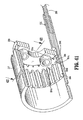
- distal neck housing 236 functions as a gear box and supports a first or proximal planetary gear system 280 and a second or distal cylindrical gear system 290.
- First planetary gear system 280 and the distal cylindrical gear system 290 function in cooperation with one another to transmit a respective translation/rotation of first drive cable or shift cable 266, or second drive cable 268 to end effector 400 to effectuate both a firing of end effector 400 and a rotation of end effector 400.
- first or proximal planetary gear system 280 and a second or distal cylindrical gear system 290 are configured to convert a rotational input of a single rotatable drive member (i.e., first drive cable or shift cable 266, second drive cable 268) into at least two output forces to end effector 400, a first output force effectuating a firing of end effector 400, and a second output force effectuating a rotation of end effector 400.
- a single rotatable drive member i.e., first drive cable or shift cable 266, second drive cable 268
- Distal neck housing 236 includes an outer tubular housing 237 defining a set of radial gear teeth 237a on an inner surface thereof, near a proximal end thereof.
- a distal end of second drive cable 268 rotatably engages a gear pair 269 supported in distal neck housing 236, wherein gear pair 269 transmits rotation to a distal drive cable 271.
- Distal drive cable 271 selectively engages a first spur gear 238a supported on distal neck housing 236.
- First spur gear 238a is in engagement with a second spur gear 238b that is non-rotatably supported on a central distal drive shaft 239, wherein distal drive shaft 239 is rotatably supported in distal neck housing 236 of articulating neck assembly 230.
- first planetary gear system 280 of distal neck housing 236 includes a first sun gear 282 non-rotatably supported on distal drive shaft 239, a first ring gear 284 surrounding first sun gear 282, and a plurality of first planet gears 286 interposed between and inter-engaging first spur gear 282 and first ring gear 284.
- the plurality of first planet gears 286 are rotatably supported on respective stems 288a of a carrier 288.
- Carrier 288 is rotatably supported in distal neck housing 236.
- Carrier 288 non-rotatably supports a crown gear 289 on stems 288a, such that rotation of crown gear 289 results in rotation of carrier 288 and first planet gears 286.
- Crown gear 289 defines a plurality of teeth 289a radially around an outer rim thereof, wherein teeth 289a extend only through or from a distal surface of crown gear 289.
- distal cylindrical gear system 290 of distal neck housing 236 includes a second sun gear 292 non-rotatably supported on and extending from carrier 288 and at least one second planet gear 296 engaged with second sun gear 292.
- an annular flange extends from first ring gear 284 to extend distally beyond distal cylindrical gear system 290 to non-rotatably engage (e.g., welded, bolted, press-fit to one another) a rotation hub 311 of an end effector coupling assembly 310 such that rotation of first ring gear 284 results in rotation of hub 311 of end effector coupling assembly 310.
- distal neck housing 236 supports a lock collar gear 240 thereon.
- Lock collar gear 240 is supported on distal neck housing 236 and includes a plurality of radially outward extending teeth 240a (in the form of a spur gear) engaged with the teeth 237a of tubular housing 237, and a plurality of distally facing teeth 240b (in the form of a crown gear) that extend radially inward of an inner-most surface of lock collar gear 240.
- Lock collar gear 240 is non-rotatably slidable, relative to crown gear 289, between a proximal position, engaged with crown gear 289 of first planetary gear system 280, and a distal position, disengaged from crown gear 289.
- lock collar gear 240 In operation, when lock collar gear 240 is in the proximal engaged position with crown gear 289, as seen in FIGS. 17, 18 and 22-24 , distally facing and inwardly projecting teeth 240b thereof engage with crown teeth 289a of crown gear 289, such that crown gear 289 and carrier 288 are prevented from rotating due to radially outward extending teeth 240a of lock collar gear 240 being engaged with teeth 237a of tubular housing 237.
- lock collar gear 240 when lock collar gear 240 is in the distal disengaged position with crown gear 289, as seen in FIGS. 25 and 26 , distally facing and inwardly projecting teeth 240b thereof are disengaged from crown teeth 289a of crown gear 289, such that crown gear 289 and carrier 288 rotate due to a rotation of spur gear 282. With lock collar gear 240 disengaged from crown gear 289, crown gear 289, and thus carrier 288, are permitted to rotate.
- central distal drive shaft 239 will result in either a closing/firing and opening/retraction of end effector 400, or a rotation of end effector 400.
- lock collar gear 240 when lock collar gear 240 is located in a distal position, disengaged from crown gear 289 and locked into engagement with first ring gear 284 (as described above and shown in FIGS. 25 and 26 ), rotation of central distal drive shaft 239 will result in a closing/firing and opening/retraction of end effector 400.
- lock collar gear 240 when lock collar gear 240 is located in a proximal position, engaged with crown gear 289 and disengaged from first ring gear 284 (as described above and shown in FIGS. 17, 18 and 22-24 ), rotation of central distal drive shaft 239 will result in a rotation of end effector 400.
- lock collar gear 240 is moved to the proximal position to engage crown gear 289, and since crown gear 289 is non-rotatably connected to carrier 288 via stems 288a, non-rotation of carrier 288 results in non-rotation of crown gear 289.
- crown gear 289 incapable of rotating, rotation of central distal drive shaft 239 is transmitted to and results in rotation of first sun gear 282 and, in turn, rotation of the plurality of first planet gears 286 about their respective central axes defined by stems 288a of carrier 288.
- first planet gears 286 As first planet gears 286 are rotated about their respective central axes defined by stems 288a of carrier 288, first planet gears 286 enmesh with teeth 284a of first ring gear 284 to transmit said rotation to first ring gear 284.
- first ring gear 284 is capable of rotation relative to tubular housing 237. As so positioned, rotation of central distal drive shaft 239 rotates first sun gear 282 which causes first planet gears 286 to rotate about their respective central axes (as defined by stems 288a of carrier 288). As first planet gears 286 rotate, first planet gears 286 drive first ring gear 284 which is fixedly or non-rotatably secured to distal housing or rotation hub 311.
- end effector 400 is connected to shaft assembly 200, and specifically, when alignment stems 424a, 424b of end effector 400 are connected to rotation hub 311, a rotation of rotation hub 311 results in rotation of end effector 400.
- lock collar gear 240 is moved to the distal position to be disengaged from crown gear 289 and locked into engagement with first ring gear 284.
- first ring gear 284 With crown gear 289 permitted to rotate, rotation of central distal drive shaft 239 results in rotation of carrier 288.
- carrier 288 transmits said rotation to second sun gear 292 of distal cylindrical gear system 290.
- second sun gear 292 transmits said rotation to the at least one second gear 296.
- the second gear 296 transmits said rotation to a firing connector 297 which is configured to selective engage with a drive axle 426 (see FIGS. 27 , 29 and 30 ) of end effector 400 to thereby effectuate a firing and a closing of end effector 400.
- lock collar gear 240 is biased to the distal position, wherein lock collar gear 240 is engaged with crown gear 289. Such an arrangement acts as a failsafe, wherein shaft assembly 200 will default to a fire (or retract) mode. It is contemplated that distal neck housing 236 may include a biasing member 244 positioned so as to act on lock collar gear 240 and urge lock collar gear 240 to the proximal position.
- first drive cable or shift cable 266 of shaft assembly 200 includes a first end attached to lock collar gear 240 and a second end extending through shaft assembly 200 to be accessible from a location external of an operative field or operative cavity.
- a distal end of shift cable 266 may be secured to lock collar gear 240, and a threaded proximal end 266a of shift cable 266 may be threadably connected to an elongate coupling member 274a, in the form of a threaded nut, rotatably supported in proximal neck housing 232.
- threaded nut 247a acts of threaded proximal end 266a of shift cable 266 to move shift cable in a first axial direction (either distally or proximally) to move lock collar gear 240 in a concomitant axial direction.
- threaded nut 247a acts of threaded proximal end 266a of shift cable 266 to move shift cable in a second axial direction (opposite the first axial direction) to move lock collar gear 240 in a concomitant axial direction.
- shift cable 266 may also be biased to a distal position.
- the spring rate/constant of the biasing member associated with shift cable 266 is greater than a spring rate/constant of biasing member 244 associated with lock collar gear 240.
- shift cable 266 is capable of being pulled completely (moved proximally), even if the teeth 240b of lock collar gear 240 are aligned with the teeth 289a of crown gear 289 thus preventing engagement, the biasing member associated with shift cable 266 will hold lock collar gear 240 against crown gear 289 until distal drive shaft 239 of distal neck housing 236 is rotated, in which the torque will rotate first sun gear 282 and crown gear 289, thereby permitting the teeth 240b of lock collar gear 240 to mesh with the teeth 289a of crown gear 289.
- first and second gear systems 280, 290 in distal neck housing 236 (at a location between articulating neck assembly 230 and end effector 400), only a single rotatable drive is required to be driven/rotated through articulating neck assembly 230. Additionally, the use of first and second planetary gear systems permits a greater torque reduction in an axially shorter assembly as compared to a gear system made up of a series of compound gears.
- shaft assembly 200 further includes an end effector coupling assembly 310 supported at a distal end of distal neck housing 236 of articulating neck assembly 230.
- End effector coupling assembly 310 includes a collar 312 rotatably supported on and extending distally from distal neck housing 236 and being biased to a first radial portion.
- Collar 312 is rotatable from a first radial position to a second radial position, wherein end effector 400 is matable to end effector coupling assembly 310, and returns, by way of the bias, to the first radial position, to lock end effector 400 to shaft assembly 200.
- the bias may be achieved by a compression spring disposed in an outer annular groove formed in rotation hub 311 and which acts on a tab or other feature provided in collar 312.
- collar 312 includes at least one nub 312a extending radially inward from inner surface thereof for receipt in a respective complementary structure 422a formed in an outer surface of end effector 400 to connect end effector 400 to shaft assembly 200 in the manner of a bayonet-type connection.
- Other forms of connection are contemplated, such as, detents, threaded connections, etc.
- end effector assembly 400 includes a drive axle 426 rotatably supported and projecting proximally from coupling member 422 and being configured for mating engagement with firing connector 297 of distal neck housing 236, when end effector 400 is coupled to shaft assembly 200.
- Drive axle 426 functions to transmit rotational drive forces from firing connector 297 of distal neck housing 236 of shaft assembly 200, to a drive screw 464 of a lower jaw of the jaw assembly of end effector 400.
- coupling member 422 includes a pair of spaced apart alignment stems 424a, 424b projecting proximally therefrom, for receipt in respective alignment bores 310a, 310b formed in a distal surface of end effector coupling assembly 310.
- shaft assembly 200 may be provided with at least one clutch mechanism (not shown) in order to reduce incidents of an end user over-torquing the gears of distal neck housing 236.
- the at least one clutch mechanism include a first clutch mechanism (not shown) interposed between lock collar gear 540 and crown gear 589, when lock collar gear 540 is in the proximal position, and a second clutch mechanism (not shown) interposed between lock collar gear 540 and first ring gear 584, when lock collar gear 540 is in the distal position. In this manner, if a user manually grabs the end effector and rotates the end effector relative to the adapter assembly, the lead screw of the end effector is not displaced.
- each clutch mechanism may include a friction enhancing material, such as, for example (steel on steel, or a rubber or silicone overmold).
- a clutch force between lock collar gear 540 and crown gear 589 may be controlled by an amount of tension exerted on lock collar gear 540 by shift cable 246.
- the clutch force is relatively higher (i.e., a relatively greater torque is required to rotate lock collar gear 540 relative to crown gear 589).
- the clutch force is relatively lower (i.e., a relatively reduced torque is required to rotate lock collar gear 540 relative to crown gear 589).
- a clutch force between lock collar gear 540 and first ring gear 584 may be controlled by an amount of any distally oriented force exerted on lock collar gear 540.
- the clutch force is relatively higher (i.e., a relatively greater torque is required to rotate lock collar gear 540 relative to first ring gear 584). It follows that when the distally oriented force exerted on lock collar gear 540 is relatively lower, the clutch force is relatively lower (i.e., a relatively reduced torque is required to rotate lock collar gear 540 relative to first ring gear 584).
- shaft assembly 200 may be provided with a clutch mechanism including a series of ramped gear teeth 540b formed on/in inner surface of a lock collar gear 540 and a series of ramped gear teeth 589a formed on/in outer surface of crown gear 589.
- a clutch force may be controlled by a number of gear teeth 540b, 589a, a dimension of gear teeth 540b, 589d, or the like.
- a proximal surface of each ramped gear tooth 540b of lock collar gear 540 is chamfered at an angle
- a distal surface of each ramped gear tooth 589a of crown gear 589 is chamfered at an angle. It is contemplated that the angle of the proximal surface of each ramped gear tooth 540b of lock collar gear 540 is substantially complementary to the angle of the distal surface of each ramped gear tooth 589a of crown gear 589.
- each ramped gear tooth 540b of lock collar gear 540 includes a pair of surfaces extending in opposite directions from one another along a plane extending radially from a central axis of lock collar gear 540, wherein the pair of surface diverge from one another in a distal direction.
- the distal surface of each ramped gear tooth 589a of crown gear 589 includes a pair of surfaces extending in opposite directions from one another along a plane extending radially from a central axis of crown gear 589, wherein the pair of surface diverge from one another in a proximal direction.
- the gears of distal neck housing 236 receives a torque or rotational force from surgical instrument 100. While this torque is highly controlled and may be precisely limited, it is possible that when lock collar gear 540 is in the proximal rotation position (as described above), a user may forcibly (i.e., manually) rotate or exert a torque on end effector 400, whereby the motors or other components of surgical instrument 100 and/or neck assembly 200 may be damaged.
- the angle of the ramped gear teeth 540b, 589a of the clutch mechanism functions to limit the amount of torque that an end user can overload.
- the amount of torque required to cause the clutch mechanism to slip is dependent on the number of gear teeth 540b, 589a; the angle of inclination of the pair of proximal surfaces of each ramped gear tooth 540b of lock collar gear 540 and the angle of inclination of the pair of distal surfaces of each ramped gear tooth 589a of crown gear 589, or the like.
- a failure mode of surgical instrument 100 from an over torquing of the motor of surgical instrument 100, may be reduced or eliminated.
- lock collar gear 540 of shaft assembly 200 have been replaced by a lock pin 560 translatably supported in distal neck housing 236 so as to selectively engage first ring gear 584, when in an advanced position, and crown gear 589, when in a retracted position.
- locking pin 560 includes a cylindrical body 562 defining a distal end 562a, and a proximal end 562b. Distal end 562a of cylindrical body 562 defines a flat or recess 562c formed in a side surface thereof.
- Locking pin 560 includes a tooth 564 supported or integrally formed at distal end 562a of cylindrical body 562. Tooth 564 includes a distal portion 564a extending distally from a distal-most end of cylindrical body 562. Tooth 564 includes a proximal portion 564b extending proximally from the distal-most end of cylindrical body 562 and projecting into the flat 562c of cylindrical body 562. Proximal portion 564b of tooth 564 defines a taper or the like.
- locking pin 560 is supported in distal neck housing 236 such that crown gear 589 is disposed within the flat 562c of locking pin 560 and adjacent proximal tapered portion 564b of tooth 564.
- first ring gear 584 is provided with an annular array of notches 584b formed in a proximal-most surface thereof. Each notch 584b is configured and dimensioned to selectively receive distal portion 564a of tooth 564 of locking pin 560.
- locking pin 560 is translatable between a retracted position, wherein proximal portion 564b of tooth 564 of locking pin 560 is engaged in teeth 589a of crown gear 589, and an advanced position, wherein distal portion 564a of tooth 564 of locking pin 560 is disposed in a notch 584a of first ring gear 584.
- Locking pin 560 is caused to be translated between the retracted and advanced positions by a push/pull or shift cable 246 that is secured to a proximal end of locking pin 560.
- a proximal end of locking pin 560 may be crimpled onto a distal end of shift cable 246. In this manner, as shift cable 246 is axially translated between retracted and advanced positions, shift cable 246 translates locking pin 560 between respective retracted and advanced positions.
- proximal portion 564b of tooth 564 of locking pin 560 engages with crown teeth 589a of crown gear 589, such that crown gear 589 and carrier 288 are prevented from rotating due to body 562 of locking pin 564 being engaged with teeth 237a of tubular housing 237 (see FIG. 37 ).
- distal portion 564a of locking pin 560 is disengaged from crown gear 589 and locked into engagement with first ring gear 584.
- rotation of central distal drive shaft 239 results in rotation of carrier 288.
- carrier 288 transmits said rotation to second sun gear 292 of distal cylindrical gear system 290.
- second sun gear 292 transmits said rotation to the at least one second gear 296.
- the second gear 296 transmits said rotation to a firing connector 297 which is configured to selective engage with a drive axle 426 (see FIGS. 27 , 29 and 30 ) of end effector 400 to thereby effectuate a firing and a closing of end effector 400.
- rotation of central distal drive shaft 239 will result in either a closing/firing and opening/retraction of end effector 400, or a rotation of end effector 400.
- rotation of central distal drive shaft 239 will result in a closing/firing and opening/retraction of end effector 400.
- rotation of central distal drive shaft 239 will result in a rotation of end effector 400.
- first ring gear 284 is capable of rotation relative to tubular housing 237. As so positioned, rotation of central distal drive shaft 239 rotates first sun gear 282 which causes first planet gears 286 to rotate about their respective central axes (as defined by stems 288a of carrier 288). As first planet gears 286 rotate, first planet gears 286 drive first ring gear 284 which is fixedly or non-rotatably secured to distal housing or rotation hub 311.
- end effector 400 is connected to shaft assembly 200, and specifically, when alignment stems 424a, 424b of end effector 400 are connected to rotation hub 311, a rotation of rotation hub 311 results in rotation of end effector 400.
- locking pin 560 is moved to the distal position to be disengaged from crown gear 589 and locked into engagement with first ring gear 284.
- crown gear 589 permitted to rotate, rotation of central distal drive shaft 239 results in rotation of carrier 288.
- carrier 288 transmits said rotation to second sun gear 292 of distal cylindrical gear system 290.
- second sun gear 292 transmits said rotation to the at least one second gear 296.
- the second gear 296 transmits said rotation to a firing connector 297 which is configured to selective engage with a drive axle 426 (see FIGS. 27 , 29 and 30 ) of end effector 400 to thereby effectuate a firing and a closing of end effector 400.
- surgical instrument 100 and/or cartridge assembly 410 need not apply staples but rather may apply two part fasteners as is known in the art.
- the length of the linear row of staples or fasteners may be modified to meet the requirements of a particular surgical procedure.
- the length of the linear row of staples and/or fasteners within a staple cartridge assembly may be varied accordingly. Therefore, the above description should not be construed as limiting, but merely as exemplifications of preferred embodiments. Those skilled in the art will envision other modifications within the scope and spirit of the claims appended thereto.
Abstract

Description
- This application claims the benefit of and priority to
U.S. Provisional Patent Application No. 61/673,792, filed July 20, 2012 - The present disclosure relates to surgical apparatus, devices and/or systems for performing endoscopic surgical procedures and methods of use thereof. More specifically, the present disclosure relates to selectable gear boxes for electromechanical, hand-held surgical apparatus, devices and/or systems configured for use with removable disposable loading units and/or single use loading units for clamping, cutting and/or stapling tissue.
- A number of surgical device manufacturers have developed product lines with proprietary drive systems for operating and/or manipulating electromechanical surgical devices. Some electromechanical surgical devices include a handle assembly, which is reusable, and replaceable loading units and/or single use loading units or the like that are selectively connected to the handle assembly prior to use and then disconnected from the handle assembly following use, in order to be disposed of or in some instances sterilized for re-use.
- Many of these electromechanical surgical devices are relatively expensive to manufacture, purchase and/or operate. There is a desire by manufactures and end users to develop electromechanical surgical devices that are relatively inexpensive to manufacture, purchase and/or operate.
- Accordingly, a need exists for electromechanical surgical apparatus, devices and/or systems that are relatively economical to develop and manufacture, to store and ship, as well as economical and convenient to purchase and use from the end user's perspective.
- An additional need exists for the electromechanical surgical apparatus to incorporate a gear box that reduces a number of drive cables extending through an articulating neck assembly.
- The present disclosure relates to selectable gear boxes for electromechanical, hand-held surgical apparatus, devices and/or systems configured for use with removable disposable loading units and/or single use loading units for clamping, cutting and/or stapling tissue.
- According to an aspect of the present disclosure, an electromechanical surgical system is provided and includes a hand-held surgical instrument including an instrument housing defining a connecting portion for selectively connecting with a shaft assembly, the surgical instrument having at least one rotatable drive member; an end effector configured to perform at least one function; and the shaft assembly being arranged for selectively interconnecting the end effector and the surgical device.
- The shaft assembly includes a transmission housing configured and adapted for selective connection to the connecting portion of the surgical device and to be in operative communication with each of the at least one rotatable drive member of the surgical device; an outer tubular body having a proximal end supported by the transmission housing and a distal end configured and adapted for operative connection with the end effector; a distal neck housing for interconnecting a rotatable drive member of the surgical instrument and a rotation receiving member supported in the end effector. The distal neck housing includes a first end that is connectable to one rotatable drive member of the surgical instrument and a second end that is connectable to the rotation receiving member of the end effector. The force transmitting assembly transmits a rotation of the rotatable drive member of the surgical instrument to the rotation receiving member of the end effector. The distal neck assembly includes at least one gear system configured to convert a rotational input of the rotatable drive member into at least two output forces to the end effector. The shaft assembly further includes an articulating neck assembly interconnecting the tubular body and the distal neck housing, wherein the articulating neck assembly is configured to enable off-axis articulation of the distal neck assembly, and wherein the rotatable drive member extends through the articulating neck assembly.
- A first output force of the at least one gear system of the distal neck housing may result in a firing of the end effector. A first output force of the at least one gear system of the distal neck housing may result in a rotation of the end effector relative to the shaft assembly.
- The distal neck housing may non-rotatably and slidably support a lock collar gear, wherein the lock collar gear includes a first position wherein the first output force of the at least one gear system of the distal neck housing results in the firing of the end effector, and wherein the first output force of the at least one gear system of the distal neck housing results in the rotation of the end effector relative to the shaft assembly.
- The distal neck housing may include an outer tubular housing defining at least one tooth extending radially inward therefrom; and a first gear system supported in the outer tubular housing. The first gear system may include a first sun gear drivable by the one rotatable drive member of the surgical instrument; a ring gear rotatably supported in the outer tubular housing; at least one first planet gear interposed and inter-engaging the first sun gear and the ring gear; and a carrier rotatably supported in the outer tubular housing, the carrier including a respective stem rotatably supporting each first planet gear. In use, when the first sun gear rotates each first planet gear about an axis of rotation of first sun gear, the end effector may be fired. Also in use, when the first sun gear rotates each first planet gear about a respective axis of rotation, the end effector may be rotated.
- The distal neck housing may include a crown gear non-rotatably connected to the carrier; and a lock collar gear axially, non-rotatably and slidably supported in the outer tubular housing. The lock collar gear may include a first position wherein the lock collar gear engages the crown gear and prevents the crown gear from rotating, wherein non-rotation of the crown gear permits the rotation of the end effector. The lock collar gear may include a second position wherein the lock collar gear is disengaged from the crown gear and permits the crown gear to rotate, wherein rotation of the crown gear permits the firing of the end effector.
- The distal neck housing include a rotation hub non-rotatably supported in outer tubular housing; and a second gear system supported in the rotation hub. The second gear system may include a second sun gear non-rotatably connected to the carrier; and at least one second planet gear rotatably supported in the rotation hub and inter-engaged with the second sun gear; and a firing connector connected to one of the at least one second planet gear, wherein the firing connector is configured to engage a force receiving member of the end effector. In use, when the carrier rotates, the second sun gear may be rotated to rotate the at least one second planet gear and to fire the end effector.
- The distal neck housing may include a first clutch mechanism interposed between and interconnecting the lock collar gear and the crown gear, when the lock collar gear is in the first position. The distal neck housing may include a second clutch mechanism interposed between and interconnecting the lock collar gear and the first ring gear, when the lock collar gear is in the second position. At least one of the first clutch mechanism and the second clutch mechanism may include friction enhancing materials interposed between respective lock collar gear and crown gear, and lock collar gear and first ring gear.
- The hand-held surgical instrument may further include at least one drive motor supported in the instrument housing and being configured to rotate the at least one rotatable drive member; a battery disposed within the instrument housing for powering the at least one drive motor; and a circuit board disposed within the instrument housing for controlling power delivered from the battery to the motor.
- The end effector may include an upper jaw and a lower jaw, at least one of the upper jaw and the lower jaw being movable in relation to the other of the upper jaw and the lower jaw.
- The electromechanical surgical system may further comprise at least one surgical buttress releasably secured to a tissue contacting surface of at least one of the upper jaw and the lower jaw.
- The electromechanical surgical system may further comprise a drive beam translatable through at least one of the upper jaw and the lower jaw to move the lower jaw relative to the upper jaw.
- The end effector may include an upper jaw and a lower jaw, at least one of the upper jaw and the lower jaw being movable in relation to the other of the upper jaw and the lower jaw; a cartridge assembly supported in the lower jaw, the cartridge assembly including a plurality of staples therein; at least one surgical buttress releasably secured to a tissue contacting surface of at least one of the upper jaw and the lower jaw, the at least one surgical buttress secured to the at least one of the upper jaw and the lower jaw by at least one suture, the at least one of the upper jaw and the lower jaw being configured to receive a portion of the at least one suture.
- The lower jaw of the end effector may be configured to selectively receive a cartridge assembly. The cartridge assembly may include a cartridge body defining a longitudinally extending knife slot; a plurality of staples disposed in individual staple retaining slots formed in the cartridge body, wherein the staple retaining slots are arranged in multiple longitudinally extending rows disposed on opposed lateral sides of the knife slot; an actuation sled slidably supported in the cartridge body and being configured to expel at least a portion of the plurality of staples from the cartridge body upon a distal movement of the actuation sled from a proximal-most position; and a knife sled slidably supported in the cartridge body at a location proximal of the actuation sled, wherein the knife sled includes a knife blade extending into the knife slot. In use, the drive beam may engage the knife sled and the actuation sled when the cartridge assembly is disposed in the lower jaw and when the drive beam is advanced.
- The actuation sled of the cartridge assembly may remain in a distally advanced position following any retraction of the drive beam.
- The knife sled of the cartridge assembly may include a lock-out spring extending therefrom, wherein the lock-out spring of the knife sled engages a lock-out notch defined in the cartridge body to inhibit advancement of the knife sled.
- In use, when the actuation sled and the knife sled are in a proximal-most position, the actuation sled may block engagement of the lock-out spring of the knife sled with the lock-out notch of the cartridge body.
- The knife sled of the cartridge assembly may be retracted upon any retraction of the drive beam. The drive beam may include a lock clip extending therefrom, wherein the lock clip of the drive beam engages the knife sled upon any distal advancement of the drive beam such that the knife sled retracts upon a retraction of the drive beam.
- The at least one rotation receiving member of the end effector may include a drive screw rotatably supported in the lower jaw, and wherein the drive beam may be threadably supported on the drive screw, whereby rotation of the drive screw results in axial translation of the drive beam.
- The at least one rotation receiving member of the end effector may include a drive screw rotatably supported in the lower jaw, and wherein the drive beam may be threadably supported on the drive screw, whereby rotation of the drive screw results in axial translation of the drive beam.
- The at least one force transmitting assembly of the shaft assembly may include a first gear train system interconnecting the at least one rotatable drive member of the surgical instrument and the at least one rotation receiving member of the end effector. The first gear train system varies at least one of a rate of rotation between the at least one rotatable drive member of the surgical instrument and the at least one rotation receiving member of the end effector; and an axis of rotation between the at least one rotatable drive member of the surgical instrument and the at least one rotation receiving member of the end effector.
- The shaft assembly may include an articulating neck assembly, and wherein the first gear train system is disposed proximal of the articulating neck assembly.
- The shaft assembly may include a neck housing disposed distal of the articulating neck assembly. The distal neck housing may support a neck first gear train of the at least one force transmitting assembly. The neck first gear train may interconnect an output of the first gear train system with the at least one rotation receiving member of the end effector. In use, the neck first gear train may vary at least one of a rate of rotation between the output of the first gear train system and the at least one rotation receiving member of the end effector; and an axis of rotation between the output of the first gear train system and the at least one rotation receiving member of the end effector.
- The at least one rotation receiving member of the end effector may include a drive screw rotatably supported in the lower jaw. The drive beam may be threadably supported on the drive screw, whereby rotation of the drive screw results in axial translation of the drive beam.
- The at least one rotation receiving member of the end effector may include a drive screw rotatably supported in the lower jaw. The drive beam may be threadably supported on the drive screw, whereby rotation of the drive screw results in axial translation of the drive beam.
- The at least one force transmitting assembly of the shaft assembly may include a second gear train system interconnecting another of the at least one rotatable drive member of the surgical instrument and a rotation hub rotatably supported at a distal end of the neck housing. In use, the second gear train system may vary at least one of a rate of rotation between the another at least one rotatable drive member of the surgical instrument and the rotation hub of the shaft assembly; and an axis of rotation between the another at least one rotatable drive member of the surgical instrument and the rotation hub of the shaft assembly.
- The shaft assembly may further include an articulating neck assembly supported at a distal end of the outer tube; a distal neck housing supported at a distal end of the articulating neck assembly, and first and second diametrically opposed articulation cables extending at least partially along the neck assembly, wherein each articulation cable includes a distal end anchored to the distal neck housing, and a proximal end extending into the outer tube, the proximal end of each articulation cable being secured to a respective first and second rack, each rack being operatively connected to one another by a spur gear.
- Axial displacement of the first rack in a first direction may result in axial displacement of the respective first articulation cable in the first direction; articulation of the neck assembly in a first off-axis direction; and axial displacement of the second articulation cable in a direction opposite to the first direction.
- The shaft assembly may further include a threaded rod extending proximally from the first rack; and a threaded shaft threadably connected to the threaded rod extending from the first rack, the threaded shaft being connected to another at least one drive member of the surgical instrument. In use, rotation of the another at least one drive member of the surgical instrument imparts rotation to the threaded shaft and, in turn, axial displacement of the threaded rod and first rack.
- The shaft assembly may further include an articulating neck assembly supported at a distal end of the outer tube, the neck assembly defining a central axis and being articulatable in a first plane; a distal neck housing supported at a distal end of the articulating neck assembly, first and second diametrically opposed articulation cables extending at least partially along the neck assembly; a first drive cable extending at least partially along the neck assembly and defining a first drive axis spaced a radial distance from the central axis, the first drive axis being defined by a first drive plane extending orthogonal to the first plane; and a second drive cable extending at least partially along the neck assembly and defining a second drive axis spaced a radial distance from the central axis, the second drive axis being defined by a second drive plane extending orthogonal to the first plane. The first drive cable and the second drive cable may be diametrically opposed to one another.
- According to another aspect of the present disclosure, an electromechanical surgical system is provided. The electromechanical surgical system includes a hand-held surgical instrument including an instrument housing defining a connecting portion for selectively connecting with a shaft assembly, the surgical instrument having at least one rotatable drive member. The electromechanical surgical system includes an end effector configured to perform at least one function. The shaft assembly is arranged for selectively interconnecting the end effector and the surgical device.
- The shaft assembly includes a transmission housing configured and adapted for selective connection to the connecting portion of the surgical device and to be in operative communication with each of the at least one rotatable drive member of the surgical device; an outer tubular body having a proximal end supported by the transmission housing and a distal end configured and adapted for operative connection with the end effector; and a distal neck housing for interconnecting a rotatable drive member of the surgical instrument and a rotation receiving member supported in the end effector, wherein the distal neck housing includes a first end that is connectable to one rotatable drive member of the surgical instrument and a second end that is connectable to the rotation receiving member of the end effector, wherein the force transmitting assembly transmits a rotation of the rotatable drive member of the surgical instrument to the rotation receiving member of the end effector.
- The distal neck assembly includes an outer tubular housing defining at least one tooth extending radially inward therefrom; and a first gear system supported in the outer tubular housing. The first gear system includes a first sun gear drivable by the one rotatable drive member of the surgical instrument; a ring gear rotatably supported in the outer tubular housing; at least one first planet gear interposed and inter-engaging the first sun gear and the ring gear; and a carrier rotatably supported in the outer tubular housing, the carrier including a respective stem rotatably supporting each first planet gear.
- In accordance with an aspect of the present disclosure, in one mode of operation, when the first sun gear is rotated, each first planet gear is caused to be revolved about a center axis of the first sun gear, resulting in a firing of the end effector. Also in accordance with an aspect of the present disclosure, in another mode of operation, when the first sun gear is rotated, each first planet gear is caused to be rotated about a respective axis of rotation thereof, resulting in a rotation of the end effector.
- The distal neck assembly includes a crown gear non-rotatably connected to the carrier; and a locking pin axially, non-rotatably and slidably supported in the outer tubular housing. The locking pin includes a first position wherein the locking pin engages the crown gear and prevents the crown gear from rotating, wherein non-rotation of the crown gear permits the rotation of the end effector, and the locking pin includes a second position wherein the locking pin is disengaged from the crown gear and permits the crown gear to rotate. wherein rotation of the crown gear permits the firing of the end effector.
- Further details and aspects of exemplary embodiments of the present invention are described in more detail below with reference to the appended figures.
- Embodiments of the present disclosure are described herein with reference to the accompanying drawings, wherein:
-
FIG. 1 is a perspective view of an electromechanical surgical system according to an embodiment of the present disclosure; -
FIG. 2 is a perspective view, with parts separated, of the electromechanical surgical system ofFIG. 1 ; -
FIG. 3 is a rear, perspective view of a shaft assembly and a powered surgical instrument, of the electromechanical surgical system ofFIGS. 1 and2 , illustrating a connection therebetween; -
FIG. 4 is a perspective view, with parts separated, of the shaft assembly ofFIGS. 1-3 ; -
FIG. 5 is a perspective view, with parts separated of a transmission housing of the shaft assembly; -
FIG. 6 is a perspective view of a first gear train system that is supported in the transmission housing; -
FIG. 7 is a perspective view of a second gear train system that is supported in the transmission housing; -
FIG. 8 is a perspective view of a third drive shaft that is supported in the transmission housing; -
FIG. 9 is a perspective view of a neck assembly of the shaft assembly, shown in a straight orientation; -
FIG. 10 is a perspective view of the neck assembly ofFIG. 9 , shown in an articulated condition; -
FIG. 11 is a perspective view of the neck assembly ofFIGS. 9 and 10 , with a threaded nut separated therefrom; -
FIG. 12 is a perspective view, with parts separated, of the neck assembly ofFIGS. 9-11 ; -
FIG. 13 is a cross-sectional view of the neck assembly ofFIGS. 9-12 , as taken through 13-13 ofFIG. 9 ; -
FIG. 14 an enlarged distal perspective view of a distal neck housing of the neck assembly ofFIGS. 9-12 ; -
FIG. 15 is an enlarged proximal perspective view of the distal neck housing ofFIG. 14 ; -
FIG. 16 is a perspective view, with parts separated, of the distal neck housing ofFIGS. 14 and 15 ; -
FIGS. 17 and 18 are perspective views of the distal neck housing ofFIGS. 14-16 , with an outer tubular housing removed therefrom; -
FIG. 19 is a cross-sectional view of the distal neck housing, as taken through 19-19 ofFIG. 18 ; -
FIG. 20 is a cross-sectional view of the distal neck housing, as taken through 20-20 ofFIG. 18 ; -
FIG. 21 is a cross-sectional view of the distal neck housing, as taken through 21-21 ofFIG. 18 ; -
FIG. 22 is a cross-sectional view of the distal neck housing, as taken through 22-22 ofFIG. 15 , illustrating the distal neck housing in a rotation configuration; -
FIG. 23 is a cross-sectional view of the distal neck housing, as taken through 23-23 ofFIG. 15 , illustrating the distal neck housing in a rotation configuration; -
FIG. 24 is an enlarged view of the indicated area of detail ofFIG. 22 ; -
FIG. 25 is a cross-sectional view of the distal neck housing, as taken through 22-22 ofFIG. 15 , illustrating the distal neck housing in a firing configuration; -
FIG. 26 is an enlarged view of the indicated area of detail ofFIG. 25 ; -
FIGS. 27-29 are perspective views illustrating a connection of an end effector to the distal neck housing ofFIGS. 14-26 ; -
FIG. 30 is a cross-sectional view of the end effector, as taken through 30-30 ofFIG. 27 ; -
FIG. 31 is a cross-sectional view of a distal neck housing according to another embodiment of the present disclosure, as taken through 22-22 ofFIG. 15 , illustrating a crown gear and a lock collar gear according to another embodiment of the present disclosure; -
FIG. 32 is an enlarged view of the indicated area of detail ofFIG. 31 ; -
FIG. 33 is a front, perspective view of the crown gear ofFIGS. 31 and 32 ; -
FIG. 34 is an enlarged view of the indicated area of detail ofFIG. 33 ; -
FIG. 35 is a rear, perspective view of the crown gear ofFIGS. 31 and 32 ; -
FIG. 36 is a cross-sectional view as taken through 36-36 ofFIG. 35 ; -
FIG. 37 is a rear, perspective view of a distal neck housing according to yet another embodiment of the present disclosure; -
FIG. 38 is a top, perspective view of a locking pin of the distal neck housing ofFIG. 37 ; -
FIG. 39 is a cross-sectional view of the distal neck housing ofFIGS. 37 and 38 , as taken through 39-39 ofFIG. 37 ; -
FIG. 40 is an enlarged view of the indicated area of detail ofFIG. 39 ; -
FIG. 41 is a cross-sectional view of the distal neck housing ofFIGS. 37 and 38 , with components removed therefrom, as taken through 39-39 ofFIG. 37 ; -
FIG. 42 is a plan view of the distal neck housing ofFIG. 41 ; and -
FIG. 43 is an enlarged view of the indicated area of detail ofFIG. 42 . - Embodiments of the presently disclosed electromechanical surgical system, apparatus and/or device are described in detail with reference to the drawings, in which like reference numerals designate identical or corresponding elements in each of the several views. As used herein the term "Distal" refers to that portion of the electromechanical surgical system, apparatus and/or device, or component thereof, that are farther from the user, while the term "proximal" refers to that portion of the electromechanical surgical system, apparatus and/or device, of component thereof, that are closer to the user.
- Referring initially to
FIGS. 1-3 , an electromechanical, hand-held, powered surgical system, in accordance with an embodiment of the present disclosure is shown and generally designated 10. Electromechanicalsurgical system 10 includes a surgical apparatus or device in the form of an electromechanical, hand-held, poweredsurgical instrument 100 that is configured for selective attachment thereto of a plurality ofdifferent end effectors 400, via ashaft assembly 200, that are each configured for actuation and manipulation by the electromechanical, hand-held, poweredsurgical instrument 100. In particular,surgical instrument 100 is configured for selective connection withshaft assembly 200, and, in turn,shaft assembly 200 is configured for selective connection with any one of a plurality ofdifferent end effectors 400. - Reference may be made to International Application No.
PCT/US2008/077249, filed September 22, 2008 (Inter. Pub. No.WO 2009/039506 ) andU.S. Patent Application Serial No. 12/622,827, filed on November 20, 2009 surgical instrument 100. - Generally, as illustrated in
FIGS. 1-3 ,surgical instrument 100 includes aninstrument housing 102 having alower housing portion 104, anintermediate housing portion 106 extending from and/or supported onlower housing portion 104, and anupper housing portion 108 extending from and/or supported onintermediate housing portion 106. Thesurgical instrument 100 has a controller for controlling certain functions of the surgical system, collecting data, and performing other functions.Instrument housing 102 defines a cavity therein in which a circuit board (not shown) and a drive mechanism (not shown) are situated. - The circuit board is configured to control the various operations of
surgical instrument 100, as will be set forth in additional detail below. In accordance with the present disclosure,instrument housing 102 provides a housing in which a rechargeable battery (not shown), is removably situated. The battery is configured to supply power to any of the electrical components ofsurgical instrument 100. -
Upper housing portion 108 ofinstrument housing 102 defines a nose or connectingportion 108a configured to accept a correspondingshaft coupling assembly 214 oftransmission housing 212 ofshaft assembly 200. As seen inFIG. 3 , connectingportion 108a ofupper housing portion 108 ofsurgical instrument 100 has acylindrical recess 108b that receivesshaft coupling assembly 214 oftransmission housing 212 ofshaft assembly 200 whenshaft assembly 200 is mated tosurgical instrument 100. The connectingportion 108a of thesurgical instrument 100 has at least one rotatable drive member. In particular, connectingportion 108a houses three rotatable drive members orconnectors instrument housing 102. -
Upper housing portion 108 ofinstrument housing 102 provides a housing in which the drive mechanism (not shown) is situated. The drive mechanism is configured to drive shafts and/or gear components in order to perform the various operations ofsurgical instrument 100. In particular, the drive mechanism is configured to drive shafts and/or gear components in order to selectively moveend effector 400 relative toshaft assembly 200; to rotateanvil assembly 200 and/orend effector 400, about a longitudinal axis "X" (secFIGS. 1 and2 ), relative toinstrument housing 102; to move an upper jaw or anvil assembly 442 ofend effector 400 relative to a lower jaw or cartridge assembly 432 ofend effector 400; to articulate and/or rotate the shaft assembly; and/or to fire a stapling and cutting cartridge within cartridge assembly 432 ofend effector 400. - The
shaft assembly 200 has a force transmitting assembly for interconnecting the at least one drive member of the surgical instrument to at least one rotation receiving member of the end effector. The force transmitting assembly has a first end that is connectable to the at least one rotatable drive member and a second end that is connectable to the at least one rotation receiving member of the end effector. Whenshaft assembly 200 is mated tosurgical instrument 100, each of rotatable drive members orconnectors surgical instrument 100 couples with a correspondingrotatable connector sleeve FIGS. 3 and5 ). In this regard, the interface between corresponding first drive member orconnector 118 andfirst connector sleeve 218, the interface between corresponding second drive member orconnector 120 andsecond connector sleeve 220, and the interface between corresponding third drive member orconnector 122 andthird connector sleeve 222 are keyed such that rotation of each of drive members orconnectors surgical instrument 100 causes a corresponding rotation of the correspondingconnector sleeve shaft assembly 200. - The mating of drive members or
connectors surgical instrument 100 withconnector sleeves shaft assembly 200 allows rotational forces to be independently transmitted via each of the three respective connector interfaces. The drive members orconnectors surgical instrument 100 are configured to be independently rotated by the drive mechanism. In this regard, the controller has a function selection module (not shown) of the drive mechanism selects which drive member orconnector surgical instrument 100 is to be driven by an input drive component (not shown) of the drive mechanism. - Since each of drive members or
connectors surgical instrument 100 has a keyed and/or substantially non-rotatable interface withrespective connector sleeves shaft assembly 200, whenshaft assembly 200 is coupled tosurgical instrument 100, rotational force(s) are selectively transferred from the drive mechanism ofsurgical instrument 100 toshaft assembly 200, and on to endeffector 400, as will be discussed in greater detail below. - The selective rotation of drive member(s) or connector(s) 118, 120 and/or 122 of
surgical instrument 100 allowssurgical instrument 100 to selectively actuate different functions ofend effector 400. As will be discussed in greater detail below, selective and independent rotation of first drive member orconnector 118 ofsurgical instrument 100 corresponds to the selective and independent opening and closing ofend effector 400, and driving of a stapling/cutting component ofend effector 400. Also, the selective and independent rotation of second drive member orconnector 120 ofsurgical instrument 100 corresponds to the selective and independent articulation ofend effector 400 transverse to longitudinal axis "X" (seeFIG. 1 ). Additionally, the selective and independent rotation of third drive member orconnector 122 ofsurgical instrument 100 corresponds to the selective and independent rotation ofend effector 400 about longitudinal axis "X" (seeFIG. 1 ) relative toinstrument housing 102 ofsurgical instrument 100. - In accordance with the present disclosure, the drive mechanism may include a selector gearbox assembly (not shown); a function selection module (not shown), located proximal to the selector gearbox assembly, that functions to selectively move gear elements within the selector gearbox assembly into engagement with a second motor (not shown). The drive mechanism may be configured to selectively drive one of drive members or
connectors surgical instrument 100, at a given time. - As illustrated in
FIGS. 1 and2 ,instrument housing 102 supports a pair of finger-actuatedcontrol buttons control buttons instrument housing 102 includes, for each one of thecontrol buttons control buttons control button 124 is a respective Hall-effect switch (not shown) that is actuated upon the movement of a magnet within thecontrol button 124 upon the operatoractuating control button 124. The actuation of Hall-effect switch (not shown), corresponding to controlbutton 124, causes the circuit board to provide appropriate signals to the function selection module and the input drive component of the drive mechanism to closeend effector 400 and/or to fire a stapling/cutting cartridge withinend effector 400. - Also, located immediately proximal to
control button 126 is a respective Hall-effect switch (not shown) that is actuated upon the movement of a magnet (not shown) withincontrol button 126 upon the operatoractuating control button 126. The actuation of the Hall-effect switch, corresponding to controlbutton 126, causes the circuit board to provide appropriate signals to the function selection module and the input drive component of the drive mechanism to open/close end effector 400. - In addition, located immediately proximal to
rocker device 130 is a respective Hall-effect switch (not shown) that is actuated upon the movement of a magnet (not shown) withinrocker device 130 upon the operatoractuating rocker device 130. The actuation of the Hall-effect switch, corresponding torocker device 130, causes the circuit board to provide appropriate signals to the function selection module and the input drive component of the drive mechanism to rotateend effector 400 relative toshaft assembly 200 or rotateend effector 400 andshaft assembly 200 relative toinstrument housing 102 ofsurgical instrument 100. Specifically, movement ofrocker device 130 in a first direction causesend effector 400 and/orshaft assembly 200 to rotate relative toinstrument housing 102 in a first direction, while movement ofrocker device 130 in an opposite, e.g., second, direction causesend effector 400 and/orshaft assembly 200 to rotate relative toinstrument housing 102 in an opposite, e.g., second, direction. - Turning now to
FIGS. 1-29 ,shaft assembly 200 will be shown in detail and described.Shaft assembly 200 is configured to communicate the rotational forces of first, second and third rotatable drive members orconnectors surgical instrument 100 to endeffector 400. As mentioned above,shaft assembly 200 is configured for selective connection tosurgical instrument 100. - As seen in
FIGS. 1 ,2 and4 ,shaft assembly 200 includes an elongate, substantially rigid, outertubular body 210 having aproximal end 210a and adistal end 210; atransmission housing 212 connected toproximal end 210a oftubular body 210 and being configured for selective connection tosurgical instrument 100; and an articulatingneck assembly 230 connected todistal end 210b ofelongate body portion 210. -
Transmission housing 212 is configured to house a pair of gear train systems therein for varying a speed/force of rotation (e.g., increase or decrease) of first, second and/or third rotatable drive members orconnectors surgical instrument 100 before transmission of such rotational speed/force to endeffector 400. -
Transmission housing 212 ofshaft assembly 200 is configured and adapted to connect to connectingportion 108a ofupper housing portion 108 ofsurgical instrument 100. As seen inFIGS. 3-5 ,transmission housing 212 ofshaft assembly 200 includes ashaft coupling assembly 214 supported at a proximal end thereof. - As seen in
FIG. 5 ,transmission housing 212 andshaft coupling assembly 214 rotatably support a first proximal orinput drive shaft 224a, a second proximal orinput drive shaft 226a, and athird drive shaft 228. -
Shaft coupling assembly 214 is configured to rotatably support first, second andthird connector sleeves connector sleeves connectors surgical instrument 100, as described above. Each ofconnector sleeves input drive shaft 224a, secondinput drive shaft 226a, andthird drive shaft 228. - Shaft
drive coupling assembly 214 includes a first, a second and athird biasing member third connector sleeves members proximal drive shaft 224a, secondproximal drive shaft 226a, andthird drive shaft 228.Biasing members respective connector sleeves connector sleeves connectors surgical instrument 100 whenshaft assembly 200 is connected tosurgical instrument 100. - In particular, first, second and
third biasing members respective connector sleeves shaft assembly 200 tosurgical instrument 100, if first, second and orthird connector sleeves connectors surgical instrument 100, first, second and/or third biasing member(s) 218a, 220a and/or 222a are compressed. Thus, when the drive mechanism ofsurgical instrument 100 is engaged, drive members orconnectors surgical instrument 100 will rotate and first, second and/or third biasing member(s) 218a, 220a and/or 222a will cause respective first, second and/or third connector sleeve(s) 218, 220 and/or 222 to slide back proximally, effectively coupling drive members orconnectors surgical instrument 100 to respective firstinput drive shaft 224a, secondinput drive shaft 226a, andthird drive shaft 228, - In use, during a calibration of
surgical instrument 100, each ofdrive connectors surgical instrument 100 is rotated and the bias on connector sleeve(s) 218, 220 and 222 properly seats connector sleeve(s) 218, 220 and 222 over therespective drive connectors surgical instrument 100 when the proper alignment is reached. -
Shaft assembly 200 includes a first and a secondgear train system transmission housing 212 andtubular body 210, andadjacent coupling assembly 214. As mentioned above, eachgear train system rotatable drive connectors surgical instrument 100 before transmission of such rotational speed/force to endeffector 400. - As seen in
FIGS. 5 and6 , firstgear train system 240 includes firstinput drive shaft 224a, and a first input driveshaft spur gear 242a keyed to firstinput drive shaft 224a. Firstgear train system 240 also includes afirst transmission shaft 244 rotatably supported intransmission housing 212, a first inputtransmission spur gear 244a keyed tofirst transmission shaft 244 and engaged with first input driveshaft spur gear 242a, and a first outputtransmission spur gear 244b keyed tofirst transmission shaft 244. Firstgear train system 240 further includes a firstoutput drive shaft 246a rotatably supported intransmission housing 212 and tubular body 110, and a first output driveshaft spur gear 246b keyed to firstoutput drive shaft 246a and engaged with first outputtransmission spur gear 244b. - In accordance with the present disclosure, first input drive
shaft spur gear 242a includes 10 teeth; first inputtransmission spur gear 244a includes 18 teeth; first outputtransmission spur gear 244b includes 13 teeth; and first output driveshaft spur gear 246b includes 15 teeth. As so configured, an input rotation of firstinput drive shaft 224a is conversed to an output rotation of firstoutput drive shaft 246a by a ratio of 1:2.08. - As mentioned above, a proximal end of first
input drive shaft 224a is configured to supportfirst connector sleeve 218. - In operation, as first input drive
shaft spur gear 242a is rotated, due to a rotation of first connector sleeve 258 and firstinput drive shaft 224a, as a result of the rotation of the firstrespective drive connector 118 ofsurgical instrument 100, first input driveshaft spur gear 242a engages first inputtransmission spur gear 244a causing first inputtransmission spur gear 244a to rotate. As first inputtransmission spur gear 244a rotates,first transmission shaft 244 is rotated and thus causes first output driveshaft spur gear 246b, that is keyed tofirst transmission shaft 244, to rotate. As first output driveshaft spur gear 246b rotates, since first output driveshaft spur gear 246b is engaged therewith, first output driveshaft spur gear 246b is also rotated. As first output driveshaft spur gear 246b rotates, since first output driveshaft spur gear 246b is keyed to firstoutput drive shaft 246a, firstoutput drive shaft 246a is rotated. - As will be discussed in greater detail below,
shaft assembly 200, includingfirst gear system 240, functions to transmit operative forces fromsurgical instrument 100 to endeffector 400 in order to operate, actuate and/orfire end effector 400. - As seen in
FIGS. 5 and7 , secondgear train system 250 includes secondinput drive shaft 226a, and a second input driveshaft spur gear 252a keyed to secondinput drive shaft 226a. Secondgear train system 250 also includes afirst transmission shaft 254 rotatably supported intransmission housing 212, a first inputtransmission spur gear 254a keyed tofirst transmission shaft 254 and engaged with second input driveshaft spur gear 252a, and a first outputtransmission spur gear 254b keyed tofirst transmission shaft 254. - Second
gear train system 250 further includes asecond transmission shaft 256 rotatably supported intransmission housing 212, a second inputtransmission spur gear 256a keyed tosecond transmission shaft 256 and engaged with first outputtransmission spur gear 254b that is keyed tofirst transmission shaft 254, and a second outputtransmission spur gear 256b keyed tosecond transmission shaft 256. - Second
gear train system 250 additionally includes a secondoutput drive shaft 258a rotatably supported intransmission housing 212 andtubular body 210, and a second output driveshaft spur gear 258b keyed to secondoutput drive shaft 258a and engaged with second outputtransmission spur gear 256b. - In accordance with the present disclosure, second input drive
shaft spur gear 252a includes 10 teeth; first inputtransmission spur gear 254a includes 20 teeth; first outputtransmission spur gear 254b includes 10 teeth; second inputtransmission spur gear 256a includes 20 teeth; second outputtransmission spur gear 256b includes 10 teeth; and second output driveshaft spur gear 258b includes 15 teeth. As so configured, an input rotation of secondinput drive shaft 226a is conversed to an output rotation of secondoutput drive shaft 258a by a ratio of 1:6. - As mentioned above, a proximal end of second
input drive shaft 226a is configured to supportsecond connector sleeve 220. - In operation, as second input drive
shaft spur gear 252a is rotated, due to a rotation ofsecond connector sleeve 260 and secondinput drive shaft 226a, as a result of the rotation of the secondrespective drive connector 120 ofsurgical instrument 100, second input driveshaft spur gear 252a engages first inputtransmission spur gear 254a causing first inputtransmission spur gear 254a to rotate. As first inputtransmission spur gear 254a rotates,first transmission shaft 254 is rotated and thus causes first outputtransmission spur gear 254b, that is keyed tofirst transmission shaft 254, to rotate. As first outputtransmission spur gear 254b rotates, since second inputtransmission spur gear 256a is engaged therewith, second inputtransmission spur gear 256a is also rotated. As second inputtransmission spur gear 256a rotates,second transmission shaft 256 is rotated and thus causes second outputtransmission spur gear 256b, that is keyed tosecond transmission shaft 256, to rotate. As second outputtransmission spur gear 256b rotates, since second output driveshaft spur gear 258b is engaged therewith, second output driveshaft spur gear 258b is rotated. As second output driveshaft spur gear 258b rotates, since second output driveshaft spur gear 258b is keyed to secondoutput drive shaft 258a, secondoutput drive shaft 258a is rotated. - As will be discussed in greater detail below,
shaft assembly 200, including secondgear train system 250, functions to transmit operative forces fromsurgical instrument 100 to endeffector 400 in order rotateshaft assembly 200 and/orend effector 400 relative tosurgical instrument 100. - As mentioned above and as seen in
FIGS. 5 and8 ,transmission housing 212 andshaft coupling assembly 214 rotatably support athird drive shaft 228.Third drive shaft 228 includes aproximal end 228a configured to supportthird connector sleeve 222, and adistal end 228b extending to and operatively connected to anarticulation assembly 270 as will be discussed in greater detail below. - As seen in
FIG. 4 , elongate, outertubular body 210 ofshaft assembly 200 includes afirst half section 211a and asecond half section 211b defining at least three longitudinally extending channels through outertubular body 210 whenhalf sections output drive shaft 246a, secondoutput drive shaft 258a, andthird drive shaft 228 as firstoutput drive shaft 246a, secondoutput drive shaft 258a, andthird drive shaft 228 extend fromtransmission housing 212 to articulatingneck assembly 230. Each of firstoutput drive shaft 246a, secondoutput drive shaft 258a, andthird drive shaft 228 are elongate and sufficiently rigid to transmit rotational forces fromtransmission housing 220 to articulatingneck assembly 230. - Turning now to
FIGS. 4 and9-13 , articulatingneck assembly 230 is shown and described. Articulatingneck assembly 230 includes aproximal neck housing 232, a plurality oflinks 234 connected to and extending in series fromproximal neck housing 232; and adistal neck housing 236 connected to and extending from a distal-most link of the plurality oflinks 234. - Each
link 234 includes cooperating knuckles and clevises formed on each of aproximal surface 234a and adistal surface 234b thereof.Proximal neck housing 232 includes knuckles and/or clevises that operatively engage with the knuckles and/or clevises of a proximal-most link.Distal neck housing 236 includes knuckles and/or clevises that operatively engage with the knuckles and/or clevises of a distal-most link. The knuckles and clevises ofadjacent neck housings links 234 operatively engage with one another to define a direction and a degree of articulation ofneck assembly 230. -
Neck assembly 230 is configured to enableend effector 400 to move between a substantially linear configuration and a substantially angled, off-axis or articulated configuration. In accordance with the present disclosure, it is contemplated thatneck assembly 230 is capable of articulating in a single plane and is capable of articulating approximately 90°, and even greater than 90°. - Each
link 234 defines afirst lumen 234c (seeFIG. 12 ) therein for passage of adistal drive cable 271 therethrough; a first pair of opposed lumens 234d1, 234d2, for passage of a pair ofarticulation cables second lumen 234e oppositefirst lumen 234c. As seen inFIG. 12 , first andsecond lumens shirt cable 266 includes a proximal end keyed to a distal end of firstoutput drive shaft 246a (FIG. 4 ) via acoupling member 247a. Asecond drive cable 268 is supported inneck assembly 230 and includes a proximal end keyed to the distal end of secondoutput drive shaft 258a (FIG. 4 ) via acoupling member 247b. Each of first andsecond drive cables distal drive cable 271 is fabricated from a material that is both flexible and torsionally stiff (capable of transmitting rotational forces or torque), such as, for example, stainless steel and the like. - As seen in
FIG. 13 ,proximal neck housing 232 ofneck assembly 230 supports anarticulation assembly 270 configured and adapted to impart articulation toneck assembly 230 and/orend effector 400.Articulation assembly 270 includes a pair of opposed gear racks 272, 274 engaged with and on opposed sides of apinion gear 276.Racks proximal neck housing 232 andpinion gear 276 is rotatably supported inproximal neck housing 232. - As seen in
FIGS. 12 and13 ,rack 274 is attached to a threadedshaft 272a extending proximally therefrom and that is in threaded engagement with a distal end of an internally threadednut 278. Threadednut 278 is rotatably supported and axially fixed within apocket 232a formed inproximal neck housing 232. A proximal end of threadednut 278 is keyed to a distal end ofthird drive shaft 228. While threadedshaft 272a is shown extending fromrack 274, it is understood, and within the scope of the present disclosure, that the threaded shaft may extend fromrack 272 without departing from the principles of the present disclosure. -
Articulation cables racks articulation cable links 234 and that is secured to or anchored indistal neck housing 234. - In operation, to articulate
neck assembly 230 in a first direction,third drive shaft 228 is rotated in a first direction, as described above, to rotate threadednut 278 and axially displace threadedshaft 272a distally to axially displacerack 274 distally. Asrack 274 is displaced axially, in a distal direction, rack 274 causespinion gear 276 to be rotated and to thus act onrack 272, to axially displacerack 272 in a proximal direction. Asrack 272 is axially displaced in a proximal direction, rack 272 causesarticulation cable 262 to be drawn in a proximal direction and therebyarticulate neck assembly 230.Neck assembly 230 is permitted to articulate since axially displacement ofrack 274, in a distal direction, results in axial, distal displacement ofarticulation cable 264. - Turning now to
FIGS. 14-29 ,distal neck housing 236 functions as a gear box and supports a first or proximalplanetary gear system 280 and a second or distalcylindrical gear system 290. Firstplanetary gear system 280 and the distalcylindrical gear system 290 function in cooperation with one another to transmit a respective translation/rotation of first drive cable orshift cable 266, orsecond drive cable 268 to endeffector 400 to effectuate both a firing ofend effector 400 and a rotation ofend effector 400. In other words, first or proximalplanetary gear system 280 and a second or distalcylindrical gear system 290 are configured to convert a rotational input of a single rotatable drive member (i.e., first drive cable orshift cable 266, second drive cable 268) into at least two output forces to endeffector 400, a first output force effectuating a firing ofend effector 400, and a second output force effectuating a rotation ofend effector 400. -
Distal neck housing 236 includes an outertubular housing 237 defining a set ofradial gear teeth 237a on an inner surface thereof, near a proximal end thereof. - In an embodiment, a distal end of
second drive cable 268 rotatably engages agear pair 269 supported indistal neck housing 236, whereingear pair 269 transmits rotation to adistal drive cable 271.Distal drive cable 271 selectively engages a first spur gear 238a supported ondistal neck housing 236. First spur gear 238a is in engagement with asecond spur gear 238b that is non-rotatably supported on a centraldistal drive shaft 239, whereindistal drive shaft 239 is rotatably supported indistal neck housing 236 of articulatingneck assembly 230. - As seen in
FIGS. 16-20 and22-26 , firstplanetary gear system 280 ofdistal neck housing 236 includes afirst sun gear 282 non-rotatably supported ondistal drive shaft 239, afirst ring gear 284 surroundingfirst sun gear 282, and a plurality of first planet gears 286 interposed between and inter-engagingfirst spur gear 282 andfirst ring gear 284. The plurality of first planet gears 286 are rotatably supported on respective stems 288a of acarrier 288.Carrier 288 is rotatably supported indistal neck housing 236.Carrier 288 non-rotatably supports acrown gear 289 onstems 288a, such that rotation ofcrown gear 289 results in rotation ofcarrier 288 and first planet gears 286.Crown gear 289 defines a plurality ofteeth 289a radially around an outer rim thereof, whereinteeth 289a extend only through or from a distal surface ofcrown gear 289. - As seen in
FIGS. 16-18 and21-26 , distalcylindrical gear system 290 ofdistal neck housing 236 includes asecond sun gear 292 non-rotatably supported on and extending fromcarrier 288 and at least onesecond planet gear 296 engaged withsecond sun gear 292. In an embodiment, it is contemplated that an annular flange extends fromfirst ring gear 284 to extend distally beyond distalcylindrical gear system 290 to non-rotatably engage (e.g., welded, bolted, press-fit to one another) arotation hub 311 of an endeffector coupling assembly 310 such that rotation offirst ring gear 284 results in rotation ofhub 311 of endeffector coupling assembly 310. - Turning back to
FIGS. 16-20 and22-26 ,distal neck housing 236 supports alock collar gear 240 thereon.Lock collar gear 240 is supported ondistal neck housing 236 and includes a plurality of radially outward extendingteeth 240a (in the form of a spur gear) engaged with theteeth 237a oftubular housing 237, and a plurality of distally facingteeth 240b (in the form of a crown gear) that extend radially inward of an inner-most surface oflock collar gear 240.Lock collar gear 240 is non-rotatably slidable, relative tocrown gear 289, between a proximal position, engaged withcrown gear 289 of firstplanetary gear system 280, and a distal position, disengaged fromcrown gear 289. - In operation, when
lock collar gear 240 is in the proximal engaged position withcrown gear 289, as seen inFIGS. 17, 18 and22-24 , distally facing and inwardly projectingteeth 240b thereof engage withcrown teeth 289a ofcrown gear 289, such thatcrown gear 289 andcarrier 288 are prevented from rotating due to radially outward extendingteeth 240a oflock collar gear 240 being engaged withteeth 237a oftubular housing 237. - Also in operation, when
lock collar gear 240 is in the distal disengaged position withcrown gear 289, as seen inFIGS. 25 and 26 , distally facing and inwardly projectingteeth 240b thereof are disengaged fromcrown teeth 289a ofcrown gear 289, such thatcrown gear 289 andcarrier 288 rotate due to a rotation ofspur gear 282. Withlock collar gear 240 disengaged fromcrown gear 289,crown gear 289, and thuscarrier 288, are permitted to rotate. - In an overall operation, as
second drive cable 268 is rotated, due to a rotation of secondoutput drive shaft 258a (as described above), as seen inFIGS. 15-21 , said rotation is transmitted todistal drive cable 271gear pair 269. Asdistal drive cable 271 is rotated, said rotation is transmitted directly to centraldistal drive shaft 239 since centraldistal drive shaft 239 is non-rotatably secured todistal drive cable 271. - Depending on a positioning of
lock collar gear 240, relative tocrown gear 289 of firstplanetary gear system 280, rotation of centraldistal drive shaft 239 will result in either a closing/firing and opening/retraction ofend effector 400, or a rotation ofend effector 400. For example, in an embodiment, whenlock collar gear 240 is located in a distal position, disengaged fromcrown gear 289 and locked into engagement with first ring gear 284 (as described above and shown inFIGS. 25 and 26 ), rotation of centraldistal drive shaft 239 will result in a closing/firing and opening/retraction ofend effector 400. Moreover, in an embodiment, whenlock collar gear 240 is located in a proximal position, engaged withcrown gear 289 and disengaged from first ring gear 284 (as described above and shown inFIGS. 17, 18 and22-24 ), rotation of centraldistal drive shaft 239 will result in a rotation ofend effector 400. - Continuing with a discussion of the operation, in order to rotate
end effector 400, as seen inFIGS. 17, 18 and22-24 ,lock collar gear 240 is moved to the proximal position to engagecrown gear 289, and sincecrown gear 289 is non-rotatably connected tocarrier 288 viastems 288a, non-rotation ofcarrier 288 results in non-rotation ofcrown gear 289. Thus, withcrown gear 289 incapable of rotating, rotation of centraldistal drive shaft 239 is transmitted to and results in rotation offirst sun gear 282 and, in turn, rotation of the plurality of first planet gears 286 about their respective central axes defined by stems 288a ofcarrier 288. As first planet gears 286 are rotated about their respective central axes defined by stems 288a ofcarrier 288, first planet gears 286 enmesh withteeth 284a offirst ring gear 284 to transmit said rotation tofirst ring gear 284. - With
lock collar gear 240 locked to crowngear 289,first ring gear 284 is capable of rotation relative totubular housing 237. As so positioned, rotation of centraldistal drive shaft 239 rotatesfirst sun gear 282 which causes first planet gears 286 to rotate about their respective central axes (as defined by stems 288a of carrier 288). As first planet gears 286 rotate, first planet gears 286 drivefirst ring gear 284 which is fixedly or non-rotatably secured to distal housing orrotation hub 311. Thus, whenend effector 400 is connected toshaft assembly 200, and specifically, when alignment stems 424a, 424b ofend effector 400 are connected torotation hub 311, a rotation ofrotation hub 311 results in rotation ofend effector 400. - Continuing with a discussion of the operation, in order to close/fire and open/retract
end effector 400, as seen inFIGS. 25 and 26 ,lock collar gear 240 is moved to the distal position to be disengaged fromcrown gear 289 and locked into engagement withfirst ring gear 284. Thus, withcrown gear 289 permitted to rotate, rotation of centraldistal drive shaft 239 results in rotation ofcarrier 288. - As
carrier 288 is rotated,carrier 288 transmits said rotation tosecond sun gear 292 of distalcylindrical gear system 290. Assecond sun gear 292 is rotated,second sun gear 292 transmits said rotation to the at least onesecond gear 296. As thesecond gear 296 is rotated, thesecond gear 296 transmits said rotation to afiring connector 297 which is configured to selective engage with a drive axle 426 (seeFIGS. 27 ,29 and30 ) ofend effector 400 to thereby effectuate a firing and a closing ofend effector 400. - In accordance with an embodiment of the present disclosure, it is contemplated that
lock collar gear 240 is biased to the distal position, whereinlock collar gear 240 is engaged withcrown gear 289. Such an arrangement acts as a failsafe, whereinshaft assembly 200 will default to a fire (or retract) mode. It is contemplated thatdistal neck housing 236 may include a biasingmember 244 positioned so as to act onlock collar gear 240 and urgelock collar gear 240 to the proximal position. - In accordance with an embodiment of the present disclosure, as seen in
FIGS. 9, 10 ,12 ,14-16 ,18 and 24-28 , it is contemplated that first drive cable orshift cable 266 ofshaft assembly 200 includes a first end attached to lockcollar gear 240 and a second end extending throughshaft assembly 200 to be accessible from a location external of an operative field or operative cavity. In particular, a distal end ofshift cable 266 may be secured to lockcollar gear 240, and a threadedproximal end 266a ofshift cable 266 may be threadably connected to anelongate coupling member 274a, in the form of a threaded nut, rotatably supported inproximal neck housing 232. In this manner, as threadednut 247a is rotated in a first direction, as by firstoutput drive shaft 266a, threadednut 247a acts of threadedproximal end 266a ofshift cable 266 to move shift cable in a first axial direction (either distally or proximally) to movelock collar gear 240 in a concomitant axial direction. Moreover, as threadednut 247a is rotated in a second direction (opposite the first direction), as by firstoutput drive shaft 266a, threadednut 247a acts of threadedproximal end 266a ofshift cable 266 to move shift cable in a second axial direction (opposite the first axial direction) to movelock collar gear 240 in a concomitant axial direction. - In a further embodiment, it is contemplated that
shift cable 266 may also be biased to a distal position. In an embodiment, the spring rate/constant of the biasing member associated withshift cable 266 is greater than a spring rate/constant of biasingmember 244 associated withlock collar gear 240. - As so configured,
shift cable 266 is capable of being pulled completely (moved proximally), even if theteeth 240b oflock collar gear 240 are aligned with theteeth 289a ofcrown gear 289 thus preventing engagement, the biasing member associated withshift cable 266 will holdlock collar gear 240 againstcrown gear 289 untildistal drive shaft 239 ofdistal neck housing 236 is rotated, in which the torque will rotatefirst sun gear 282 andcrown gear 289, thereby permitting theteeth 240b oflock collar gear 240 to mesh with theteeth 289a ofcrown gear 289. - The reverse occurs when
shift cable 266 is released from a proximal position. Withlock collar gear 240 spring loaded towardscrown gear 289, even if the teeth oflock collar gear 240 are aligned with the teeth ofcrown 289 thus preventing engagement, biasing member 242 will holdlock collar gear 240 againstcrown gear 289 untildistal drive shaft 239 ofdistal neck housing 236 is rotated, in which the torque will rotatefirst sun gear 282 andcrown gear 289, thereby permitting the teeth oflock collar gear 240 to en-mesh with the teeth ofcrown gear 289. - By providing first and
second gear systems neck assembly 230 and end effector 400), only a single rotatable drive is required to be driven/rotated through articulatingneck assembly 230. Additionally, the use of first and second planetary gear systems permits a greater torque reduction in an axially shorter assembly as compared to a gear system made up of a series of compound gears. - As seen in
FIGS. 14, 15 and27-29 ,shaft assembly 200 further includes an endeffector coupling assembly 310 supported at a distal end ofdistal neck housing 236 of articulatingneck assembly 230. Endeffector coupling assembly 310 includes acollar 312 rotatably supported on and extending distally fromdistal neck housing 236 and being biased to a first radial portion.Collar 312 is rotatable from a first radial position to a second radial position, whereinend effector 400 is matable to endeffector coupling assembly 310, and returns, by way of the bias, to the first radial position, to lockend effector 400 toshaft assembly 200. In an embodiment, the bias may be achieved by a compression spring disposed in an outer annular groove formed inrotation hub 311 and which acts on a tab or other feature provided incollar 312. - It is contemplated that
collar 312 includes at least onenub 312a extending radially inward from inner surface thereof for receipt in a respective complementary structure 422a formed in an outer surface ofend effector 400 to connectend effector 400 toshaft assembly 200 in the manner of a bayonet-type connection. Other forms of connection are contemplated, such as, detents, threaded connections, etc. - Turning now to
FIGS. 27-30 , anexemplary end effector 400, for use withsurgical instrument 100 andshaft assembly 200 is shown. Reference may be made toU.S. Patent Application Serial No. 13/280,898, filed on October 25, 2011 end effector 400. As seen inFIGS. 27-30 ,end effector assembly 400 includes adrive axle 426 rotatably supported and projecting proximally from couplingmember 422 and being configured for mating engagement with firingconnector 297 ofdistal neck housing 236, whenend effector 400 is coupled toshaft assembly 200. Driveaxle 426 functions to transmit rotational drive forces from firingconnector 297 ofdistal neck housing 236 ofshaft assembly 200, to adrive screw 464 of a lower jaw of the jaw assembly ofend effector 400. - As seen in
FIGS. 27-30 ,coupling member 422 includes a pair of spaced apart alignment stems 424a, 424b projecting proximally therefrom, for receipt in respective alignment bores 310a, 310b formed in a distal surface of endeffector coupling assembly 310. - In an embodiment, it is contemplated that
shaft assembly 200 may be provided with at least one clutch mechanism (not shown) in order to reduce incidents of an end user over-torquing the gears ofdistal neck housing 236. It is contemplated that the at least one clutch mechanism include a first clutch mechanism (not shown) interposed betweenlock collar gear 540 andcrown gear 589, whenlock collar gear 540 is in the proximal position, and a second clutch mechanism (not shown) interposed betweenlock collar gear 540 andfirst ring gear 584, whenlock collar gear 540 is in the distal position. In this manner, if a user manually grabs the end effector and rotates the end effector relative to the adapter assembly, the lead screw of the end effector is not displaced. - It is contemplated that, in an embodiment, each clutch mechanism may include a friction enhancing material, such as, for example (steel on steel, or a rubber or silicone overmold). In this embodiment, a clutch force between
lock collar gear 540 andcrown gear 589 may be controlled by an amount of tension exerted onlock collar gear 540 by shift cable 246. In particular, when the tension force exerted onlock collar gear 540 is relatively higher, the clutch force is relatively higher (i.e., a relatively greater torque is required to rotatelock collar gear 540 relative to crown gear 589). It follows that when the tension force exerted onlock collar gear 540 is relatively lower, the clutch force is relatively lower (i.e., a relatively reduced torque is required to rotatelock collar gear 540 relative to crown gear 589). - Additionally, a clutch force between
lock collar gear 540 andfirst ring gear 584 may be controlled by an amount of any distally oriented force exerted onlock collar gear 540. In particular, when the distally oriented force exerted onlock collar gear 540 is relatively higher, the clutch force is relatively higher (i.e., a relatively greater torque is required to rotatelock collar gear 540 relative to first ring gear 584). It follows that when the distally oriented force exerted onlock collar gear 540 is relatively lower, the clutch force is relatively lower (i.e., a relatively reduced torque is required to rotatelock collar gear 540 relative to first ring gear 584). - In an additional embodiment, it is further contemplated that, as seen in
FIGS. 31-36 , thatshaft assembly 200 may be provided with a clutch mechanism including a series of rampedgear teeth 540b formed on/in inner surface of alock collar gear 540 and a series of rampedgear teeth 589a formed on/in outer surface ofcrown gear 589. In this embodiment, a clutch force may be controlled by a number ofgear teeth gear teeth 540b, 589d, or the like. - In particular, a proximal surface of each ramped
gear tooth 540b oflock collar gear 540 is chamfered at an angle, and a distal surface of each rampedgear tooth 589a ofcrown gear 589 is chamfered at an angle. It is contemplated that the angle of the proximal surface of each rampedgear tooth 540b oflock collar gear 540 is substantially complementary to the angle of the distal surface of each rampedgear tooth 589a ofcrown gear 589. - More particularly, the proximal surface of each ramped
gear tooth 540b oflock collar gear 540 includes a pair of surfaces extending in opposite directions from one another along a plane extending radially from a central axis oflock collar gear 540, wherein the pair of surface diverge from one another in a distal direction. Additionally, the distal surface of each rampedgear tooth 589a ofcrown gear 589 includes a pair of surfaces extending in opposite directions from one another along a plane extending radially from a central axis ofcrown gear 589, wherein the pair of surface diverge from one another in a proximal direction. - In use, as described above, the gears of
distal neck housing 236 receives a torque or rotational force fromsurgical instrument 100. While this torque is highly controlled and may be precisely limited, it is possible that whenlock collar gear 540 is in the proximal rotation position (as described above), a user may forcibly (i.e., manually) rotate or exert a torque onend effector 400, whereby the motors or other components ofsurgical instrument 100 and/orneck assembly 200 may be damaged. The angle of the rampedgear teeth gear teeth gear tooth 540b oflock collar gear 540 and the angle of inclination of the pair of distal surfaces of each rampedgear tooth 589a ofcrown gear 589, or the like. - In operation, when
lock collar gear 540 is in the distal or fire position, torque fromsurgical instrument 100 is transmitted through the gears ofdistal neck housing 236 to rotate drive axle 426 (seeFIGS. 27 ,29 and30 ) ofend effector 400 to thereby effectuate a firing and a closing ofend effector 400. In this situation, the end user can not induce excessive external torque by pushing on a knife bar ofend effector 400. - However, by adding a clutch mechanism to drive
axle 426 of end effector 400 (not shown), a failure mode ofsurgical instrument 100, from an over torquing of the motor ofsurgical instrument 100, may be reduced or eliminated. - In a further embodiment, it is contemplated that, as seen in
FIGS. 37-43 , thatlock collar gear 540 ofshaft assembly 200 have been replaced by alock pin 560 translatably supported indistal neck housing 236 so as to selectively engagefirst ring gear 584, when in an advanced position, andcrown gear 589, when in a retracted position. - As seen in
FIG. 38 , lockingpin 560 includes acylindrical body 562 defining adistal end 562a, and a proximal end 562b.Distal end 562a ofcylindrical body 562 defines a flat orrecess 562c formed in a side surface thereof. Lockingpin 560 includes atooth 564 supported or integrally formed atdistal end 562a ofcylindrical body 562.Tooth 564 includes adistal portion 564a extending distally from a distal-most end ofcylindrical body 562.Tooth 564 includes aproximal portion 564b extending proximally from the distal-most end ofcylindrical body 562 and projecting into the flat 562c ofcylindrical body 562.Proximal portion 564b oftooth 564 defines a taper or the like. - As seen in
FIGS. 39-43 , lockingpin 560 is supported indistal neck housing 236 such thatcrown gear 589 is disposed within the flat 562c of lockingpin 560 and adjacent proximaltapered portion 564b oftooth 564. - With continued reference to
FIGS. 39-43 ,first ring gear 584 is provided with an annular array ofnotches 584b formed in a proximal-most surface thereof. Eachnotch 584b is configured and dimensioned to selectively receivedistal portion 564a oftooth 564 of lockingpin 560. - In operation, locking
pin 560 is translatable between a retracted position, whereinproximal portion 564b oftooth 564 of lockingpin 560 is engaged inteeth 589a ofcrown gear 589, and an advanced position, whereindistal portion 564a oftooth 564 of lockingpin 560 is disposed in a notch 584a offirst ring gear 584. - Locking
pin 560 is caused to be translated between the retracted and advanced positions by a push/pull or shift cable 246 that is secured to a proximal end of lockingpin 560. In particular, it is contemplated that a proximal end of lockingpin 560 may be crimpled onto a distal end of shift cable 246. In this manner, as shift cable 246 is axially translated between retracted and advanced positions, shift cable 246 translates lockingpin 560 between respective retracted and advanced positions. - In operation, when locking
pin 560 is in the retracted or proximal position, engaged withcrown gear 589,proximal portion 564b oftooth 564 of lockingpin 560 engages withcrown teeth 589a ofcrown gear 589, such thatcrown gear 589 andcarrier 288 are prevented from rotating due tobody 562 of lockingpin 564 being engaged withteeth 237a of tubular housing 237 (seeFIG. 37 ). - Also in operation, when locking
pin 560 is in the advanced or distal position, disengaged withcrown gear 589,proximal portion 564b oftooth 564 of lockingpin 560 is disengaged fromcrown teeth 589a ofcrown gear 589, such thatcrown gear 589 andcarrier 288 rotate due to a rotation ofspur gear 282. With lockingpin 560 disengaged fromcrown gear 589,crown gear 589, and thuscarrier 288, are permitted to rotate. - Additionally, when locking
pin 560 is in the advanced or distal position,distal portion 564a of lockingpin 560 is disengaged fromcrown gear 589 and locked into engagement withfirst ring gear 584. Thus, withcrown gear 589 permitted to rotate, rotation of centraldistal drive shaft 239 results in rotation ofcarrier 288. Ascarrier 288 is rotated,carrier 288 transmits said rotation tosecond sun gear 292 of distalcylindrical gear system 290. Assecond sun gear 292 is rotated,second sun gear 292 transmits said rotation to the at least onesecond gear 296. As thesecond gear 296 is rotated, thesecond gear 296 transmits said rotation to afiring connector 297 which is configured to selective engage with a drive axle 426 (seeFIGS. 27 ,29 and30 ) ofend effector 400 to thereby effectuate a firing and a closing ofend effector 400. - Depending on a positioning of locking
pin 560, relative tocrown gear 589 of firstplanetary gear system 280, rotation of centraldistal drive shaft 239 will result in either a closing/firing and opening/retraction ofend effector 400, or a rotation ofend effector 400. For example, in an embodiment, when lockingpin 560 is located in the advanced or distal position, disengaged from crown gear 589 (as described above), rotation of centraldistal drive shaft 239 will result in a closing/firing and opening/retraction ofend effector 400. Moreover, in an embodiment, when lockingpin 560 is located in the retracted or proximal position, engaged with crown gear 589 (as described above), rotation of centraldistal drive shaft 239 will result in a rotation ofend effector 400. - Continuing with a discussion of the operation, in order to rotate
end effector 400, lockingpin 560 is moved to the retracted or proximal position to engagecrown gear 589, and sincecrown gear 589 is non-rotatably connected tocarrier 288, via stems 288a, non-rotation ofcarrier 288 results in non-rotation ofcrown gear 589. Thus, withcrown gear 589 incapable of rotating, rotation of centraldistal drive shaft 239 is transmitted to and results in rotation offirst sun gear 282 and, in turn, rotation of the plurality of first planet gears 286 about their respective central axes defined by stems 288a ofcarrier 288. As first planet gears 286 are rotated about their respective central axes defined by stems 288a ofcarrier 288, first planet gears 286 enmesh withteeth 284a offirst ring gear 284 to transmit said rotation tofirst ring gear 284. - With
lock collar gear 540 locked to crowngear 589,first ring gear 284 is capable of rotation relative totubular housing 237. As so positioned, rotation of centraldistal drive shaft 239 rotatesfirst sun gear 282 which causes first planet gears 286 to rotate about their respective central axes (as defined by stems 288a of carrier 288). As first planet gears 286 rotate, first planet gears 286 drivefirst ring gear 284 which is fixedly or non-rotatably secured to distal housing orrotation hub 311. Thus, whenend effector 400 is connected toshaft assembly 200, and specifically, when alignment stems 424a, 424b ofend effector 400 are connected torotation hub 311, a rotation ofrotation hub 311 results in rotation ofend effector 400. - Continuing with a discussion of the operation, in order to close/fire and open/retract
end effector 400, lockingpin 560 is moved to the distal position to be disengaged fromcrown gear 589 and locked into engagement withfirst ring gear 284. Thus, withcrown gear 589 permitted to rotate, rotation of centraldistal drive shaft 239 results in rotation ofcarrier 288. - As
carrier 288 is rotated,carrier 288 transmits said rotation tosecond sun gear 292 of distalcylindrical gear system 290. Assecond sun gear 292 is rotated,second sun gear 292 transmits said rotation to the at least onesecond gear 296. As thesecond gear 296 is rotated, thesecond gear 296 transmits said rotation to afiring connector 297 which is configured to selective engage with a drive axle 426 (seeFIGS. 27 ,29 and30 ) ofend effector 400 to thereby effectuate a firing and a closing ofend effector 400. - It is contemplated that when locking
pin 560 is in a "neutral" position between the distal and proximal positions, the less restrictive of the closing/firing and rotation functions may be performed. - It will be understood that various modifications may be made to the embodiments disclosed herein. For example,
surgical instrument 100 and/or cartridge assembly 410 need not apply staples but rather may apply two part fasteners as is known in the art. Further, the length of the linear row of staples or fasteners may be modified to meet the requirements of a particular surgical procedure. Thus, the length of the linear row of staples and/or fasteners within a staple cartridge assembly may be varied accordingly. Therefore, the above description should not be construed as limiting, but merely as exemplifications of preferred embodiments. Those skilled in the art will envision other modifications within the scope and spirit of the claims appended thereto. - The invention may be described by reference to the following numbered paragraphs:-
- 1. An electromechanical surgical system, comprising:
- a hand-held surgical instrument including an instrument housing defining a connecting portion for selectively connecting with a shaft assembly, the surgical instrument having at least one rotatable drive member;
- an end effector configured to perform at least one function; and
- the shaft assembly being arranged for selectively interconnecting the end effector and the surgical device, the shaft assembly including:
- a transmission housing configured and adapted for selective connection to the connecting portion of the surgical device and to be in operative communication with each of the at least one rotatable drive member of the surgical device;
- an outer tubular body having a proximal end supported by the transmission housing and a distal end configured and adapted for operative connection with the end effector;
- a distal neck housing for interconnecting a rotatable drive member of the surgical instrument and a rotation receiving member supported in the end effector, wherein the distal neck housing includes a first end that is connectable to one rotatable drive member of the surgical instrument and a second end that is connectable to the rotation receiving member of the end effector, wherein the force transmitting assembly transmits a rotation of the rotatable drive member of the surgical instrument to the rotation receiving member of the end effector, the distal neck assembly including:
- at least one gear system configured to convert a rotational input of the rotatable drive member into at least two output forces to the end effector; and
- an articulating neck assembly interconnecting the tubular body and the distal neck housing, wherein the articulating neck assembly is configured to enable off-axis articulation of the distal neck assembly, and wherein the rotatable drive member extends through the articulating neck assembly.
- 2. The electromechanical surgical system according to
paragraph 1, wherein a first output force of the at least one gear system of the distal neck housing results in a firing of the end effector. - 3. The electromechanical surgical system according to paragraph 2, wherein a first output force of the at least one gear system of the distal neck housing results in a rotation of the end effector relative to the shaft assembly.
- 4. The electromechanical surgical system according to paragraph 3, wherein the distal neck housing non-rotatably and slidably supports a lock collar gear, wherein the lock collar gear includes a first position wherein the first output force of the at least one gear system of the distal neck housing results in the firing of the end effector, and wherein the first output force of the at least one gear system of the distal neck housing results in the rotation of the end effector relative to the shaft assembly.
- 5. The electromechanical surgical system according to paragraph 4, wherein the distal neck housing includes:
- an outer tubular housing defining at least one tooth extending radially inward therefrom; and
- a first gear system supported in the outer tubular housing, the first gear system includes:
- a first sun gear drivable by the one rotatable drive member of the surgical instrument;
- a ring gear rotatably supported in the outer tubular housing;
- at least one first planet gear interposed and inter-engaging the first sun gear and the ring gear; and
- a carrier rotatably supported in the outer tubular housing, the carrier including a respective stem rotatably supporting each first planet gear;
- wherein, in one mode of operation, when the first sun gear is rotated, each first planet gear is caused to be revolved about a center axis of the first sun gear, resulting in a firing of the end effector; and
- wherein, in another mode of operation, when the first sun gear is rotated, each first planet gear is caused to be rotated about a respective axis of rotation thereof, resulting in a rotation of the end effector.
- 6. The electromechanical surgical system according to paragraph 5, wherein the distal neck housing includes:
- a crown gear non-rotatably connected to the carrier; and
- a lock collar gear axially, non-rotatably and slidably supported in the outer tubular housing,
- wherein the lock collar gear includes a first position wherein the lock collar gear engages the crown gear and prevents the crown gear from rotate, wherein non-rotation of the crown gear permits the rotation of the end effector, and
- wherein the lock collar gear includes a second position wherein the lock collar gear is disengaged from the crown gear and permits the crown gear to rotating, wherein rotation of the crown gear permits the firing of the end effector.
- 7. The electromechanical surgical system according to paragraph 6, wherein the distal neck housing includes:
- a rotation hub non-rotatably supported in outer tubular housing; and
- a second gear system supported in the rotation hub, the second gear system includes:
- a second sun gear non-rotatably connected to the carrier; and
- at least one second planet gear rotatably supported in the rotation hub and interengaged with the second sun gear; and
- a firing connector connected to one of the at least one second planet gear, wherein the firing connector is configured to engage a force receiving member of the end effector;
- wherein when the carrier rotates, the second sun gear is rotated to rotate the at least one second planet gear and to fire the end effector.
- 8. The electromechanical surgical system according to paragraph 6, wherein the distal neck housing includes a first clutch mechanism interposed between and interconnecting the lock collar gear and the crown gear, when the lock collar gear is in the first position.
- 9. The electromechanical surgical system according to paragraph 8, wherein the distal neck housing includes a second clutch mechanism interposed between and interconnecting the lock collar gear and the first ring gear, when the lock collar gear is in the second position.
- 10. The electromechanical surgical system according to paragraph 9, wherein at least one of the first clutch mechanism and the second clutch mechanism includes friction enhancing materials interposed between respective lock collar gear and crown gear, and lock collar gear and first ring gear.
- 11. The electromechanical surgical system according to
paragraph 1, wherein the hand-held surgical instrument further includes:- at least one drive motor supported in the instrument housing and being configured to rotate the at least one rotatable drive member;
- a battery disposed within the instrument housing for powering the at least one drive motor; and
- a circuit board disposed within the instrument housing for controlling power delivered from the battery to the motor.
- 12. The electromechanical surgical system according to
paragraph 1, wherein the end effector includes:- an upper jaw and a lower jaw, at least one of the upper jaw and the lower jaw being movable in relation to the other of the upper jaw and the lower jaw.
- 13. The electromechanical surgical system according to paragraph 12, further comprising:
- at least one surgical buttress releasably secured to a tissue contacting surface of at least one of the upper jaw and the lower jaw.
- 14. The electromechanical surgical system according to paragraph 12, further comprising a drive beam translatable through at least one of the upper jaw and the lower jaw to move the lower jaw relative to the upper jaw.
- 15. The electromechanical surgical system according to paragraph 11, wherein the end effector includes:
- an upper jaw and a lower jaw, at least one of the upper jaw and the lower jaw being movable in relation to the other of the upper jaw and the lower jaw;
- a cartridge assembly supported in the lower jaw, the cartridge assembly including a plurality of staples therein;
- at least one surgical buttress releasably secured to a tissue contacting surface of at least one of the upper jaw and the lower jaw, the at least one surgical buttress secured to the at least one of the upper jaw and the lower jaw by at least one suture, the at least one of the upper jaw and the lower jaw being configured to receive a portion of the at least one suture.
- 16. The electromechanical surgical system according to paragraph 15, wherein the lower jaw of the end effector is configured to selectively receive a cartridge assembly, wherein the cartridge assembly includes:
- a cartridge body defining a longitudinally extending knife slot;
- a plurality of staples disposed in individual staple retaining slots formed in the cartridge body, wherein the staple retaining slots are arranged in multiple longitudinally extending rows disposed on opposed lateral sides of the knife slot;
- an actuation sled slidably supported in the cartridge body and being configured to expel at least a portion of the plurality of staples from the cartridge body upon a distal movement of the actuation sled from a proximal-most position; and
- a knife sled slidably supported in the cartridge body at a location proximal of the actuation sled, wherein the knife sled includes a knife blade extending into the knife slot;
- wherein the drive beam engages the knife sled and the actuation sled when the cartridge assembly is disposed in the lower jaw and when the drive beam is advanced.
- 17. The electromechanical surgical system according to paragraph 16, wherein the actuation sled of the cartridge assembly remains in a distally advanced position following any retraction of the drive beam.
- 18. The electromechanical surgical system according to paragraph 16, wherein the knife sled of the cartridge assembly includes a lock-out spring extending therefrom, wherein the lock-out spring of the knife sled engages a lock-out notch defined in the cartridge body to inhibit advancement of the knife sled.
- 19. The electromechanical surgical system according to paragraph 18, wherein, when the actuation sled and the knife sled are in a proximal-most position, the actuation sled blocks engagement of the lock-out spring of the knife sled with the lock-out notch of the cartridge body.
- 20. The electromechanical surgical system according to
paragraph 19, wherein the knife sled of the cartridge assembly is retracted upon any retraction of the drive beam. - 21. The electromechanical surgical system according to
paragraph 20, wherein the drive beam includes a lock clip extending therefrom, wherein the lock clip of the drive beam engages the knife sled upon any distal advancement of the drive beam such that the knife sled retracts upon a retraction of the drive bean. - 22. The electromechanical surgical system according to
paragraph 21, wherein the at least one rotation receiving member of the end effector includes a drive screw rotatably supported in the lower jaw, wherein the drive beam is threadably supported on the drive screw, whereby rotation of the drive screw results in axial translation of the drive beam. - 23. The electromechanical surgical system according to paragraph 12, wherein the at least one rotation receiving member of the end effector includes a drive screw rotatably supported in the lower jaw, wherein the drive beam is threadably supported on the drive screw, whereby rotation of the drive screw results in axial translation of the drive beam.
- 24. The electromechanical surgical system according to paragraph 11, wherein the at least one force transmitting assembly of the shaft assembly includes a first gear train system interconnecting the at least one rotatable drive member of the surgical instrument and the at least one rotation receiving member of the end effector, wherein the first gear train system varies at least one of:
- a rate of rotation between the at least one rotatable drive member of the surgical instrument and the at least one rotation receiving member of the end effector; and
- an axis of rotation between the at least one rotatable drive member of the surgical instrument and the at least one rotation receiving member of the end effector.
- 25. The electromechanical surgical system according to
paragraph 24, wherein the shaft assembly includes an articulating neck assembly, and wherein the first gear train system is disposed proximal of the articulating neck assembly. - 26. The electromechanical surgical system according to paragraph 25, wherein the shaft assembly includes a neck housing disposed distal of the articulating neck assembly, wherein the distal neck housing supports a neck first gear train of the at least one force transmitting assembly, wherein the neck first gear train interconnects an output of the first gear train system with the at least one rotation receiving member of the end effector, wherein the neck first gear train varies at least one of:
- a rate of rotation between the output of the first gear train system and the at least one rotation receiving member of the end effector; and
- an axis of rotation between the output of the first gear train system and the at least one rotation receiving member of the end effector.
- 27. The electromechanical surgical system according to
paragraph 24, wherein the at least one rotation receiving member of the end effector includes a drive screw rotatably supported in the lower jaw, wherein the drive beam is threadably supported on the drive screw, whereby rotation of the drive screw results in axial translation of the drive beam. - 28. The electromechanical surgical system according to
paragraph 26, wherein the at least one rotation receiving member of the end effector includes a drive screw rotatably supported in the lower jaw, wherein the drive beam is threadably supported on the drive screw, whereby rotation of the drive screw results in axial translation of the drive beam. - 29. The electromechanical surgical system according to paragraph 25, wherein the at least one force transmitting assembly of the shaft assembly includes a second gear train system interconnecting another of the at least one rotatable drive member of the surgical instrument and a rotation hub rotatably supported at a distal end of the neck housing, wherein the second gear train system varies at least one of:
- a rate of rotation between the another at least one rotatable drive member of the surgical instrument and the rotation hub of the shaft assembly; and
- an axis of rotation between the another at least one rotatable drive member of the surgical instrument and the rotation hub of the shaft assembly.
- 30. The electromechanical surgical system according to
paragraph 24, wherein the shaft assembly further includes:- an articulating neck assembly supported at a distal end of the outer tube;
- a distal neck housing supported at a distal end of the articulating neck assembly, and
- first and second diametrically opposed articulation cables extending at least partially along the neck assembly, wherein each articulation cable includes a distal end anchored to the distal neck housing, and a proximal end extending into the outer tube, the proximal end of each articulation cable being secured to a respective first and second rack, each rack being operatively connected to one another by a spur gear,
- wherein axial displacement of the first rack in a first direction results in:
- axial displacement of the respective first articulation cable in the first direction;
- articulation of the neck assembly in a first off-axis direction; and
- axial displacement of the second articulation cable in a direction opposite to the first direction.
- 31. The electromechanical surgical system according to
paragraph 30, wherein the shaft assembly further includes:- a threaded rod extending proximally from the first rack; and
- a threaded shaft threadably connected to the threaded rod extending from the first rack, the threaded shaft being connected to another at least one drive member of the surgical instrument,
- wherein rotation of the another at least one drive member of the surgical instrument imparts rotation to the threaded shaft and, in turn, axial displacement of the threaded rod and first rack.
- 32. The electromechanical surgical system according to
paragraph 24, wherein the shaft assembly further includes:- an articulating neck assembly supported at a distal end of the outer tube, the neck assembly defining a central axis and being articulatable in a first plane;
- a distal neck housing supported at a distal end of the articulating neck assembly,
- first and second diametrically opposed articulation cables extending at least partially along the neck assembly;
- a first drive cable extending at least partially along the neck assembly and defining a first drive axis spaced a radial distance from the central axis, the first drive axis being defined by a first drive plane extending orthogonal to the first plane; and
- a second drive cable extending at least partially along the neck assembly and defining a second drive axis spaced a radial distance from the central axis, the second drive axis being defined by a second drive plane extending orthogonal to the first plane;
- wherein the first drive cable and the second drive cable are diametrically opposed to one another.
- 33. An electromechanical surgical system, comprising:
- a hand-held surgical instrument including an instrument housing defining a connecting portion for selectively connecting with a shaft assembly, the surgical instrument having at least one rotatable drive member;
- an end effector configured to perform at least one function; and
- the shaft assembly being arranged for selectively interconnecting the end effector and the surgical device, the shaft assembly including:
- a transmission housing configured and adapted for selective connection to the connecting portion of the surgical device and to be in operative communication with each of the at least one rotatable drive member of the surgical device;
- an outer tubular body having a proximal end supported by the transmission housing and a distal end configured and adapted for operative connection with the end effector;
- a distal neck housing for interconnecting a rotatable drive member of the surgical instrument and a rotation receiving member supported in the end effector, wherein the distal neck housing includes a first end that is connectable to one rotatable drive member of the surgical instrument and a second end that is connectable to the rotation receiving member of the end effector, wherein the force transmitting assembly transmits a rotation of the rotatable drive member of the surgical instrument to the rotation receiving member of the end effector, the distal neck assembly including:
- an outer tubular housing defining at least one tooth extending radially inward therefrom;
- a first gear system supported in the outer tubular housing, the first gear system includes:
- a first sun gear drivable by the one rotatable drive member of the surgical instrument;
- a ring gear rotatably supported in the outer tubular housing;
- at least one first planet gear interposed and inter-engaging the first sun gear and the ring gear; and
- a carrier rotatably supported in the outer tubular housing, the carrier including a respective stem rotatably supporting each first planet gear;
- wherein when the first sun gear rotates each first planet gear about an axis of rotation of first sun gear, the end effector is fired; and
- wherein when the first sun gear rotates each first planet gear about a respective axis of rotation, the end effector is rotated;
- a crown gear non-rotatably connected to the carrier; and
- a locking pin axially, non-rotatably and slidably supported in the outer tubular housing,
wherein the locking pin includes a first position wherein the locking pin engages the crown gear and prevents the crown gear from rotating, wherein non-rotation of the crown gear permits the rotation of the end effector, and
wherein the locking pin includes a second position wherein the locking pin is disengaged from the crown gear and permits the crown gear to rotate, wherein rotation of the crown gear permits the firing of the end effector.
- 34. The electromechanical surgical system according to paragraph 33, wherein shaft assembly is configured to convert a rotational input of the rotatable drive member into at least two output forces to the end effector.
- 35. The electromechanical surgical system according to paragraph 33, wherein the shaft assembly further includes:
- an articulating neck assembly interconnecting the tubular body and the distal neck housing, wherein the articulating neck assembly is configured to enable off-axis articulation of the distal neck assembly, and wherein the rotatable drive member extends through the articulating neck assembly.
- 36. The electromechanical surgical system according to paragraph 35, wherein the distal neck housing includes:
- a rotation hub non-rotatably supported in outer tubular housing; and
- a second gear system supported in the rotation hub, the second gear system includes:
- a second sun gear non-rotatably connected to the carrier; and
- at least one second planet gear rotatably supported in the rotation hub and interengaged with the second sun gear; and
- a firing connector connected to one of the at least one second planet gear, wherein the firing connector is configured to engage a force receiving member of the end effector;
- 37. The electromechanical surgical system according to paragraph 33, wherein the hand-held surgical instrument further includes:
- at least one drive motor supported in the instrument housing and being configured to rotate the at least one rotatable drive member;
- a battery disposed within the instrument housing for powering the at least one drive motor; and
- a circuit board disposed within the instrument housing for controlling power delivered from the battery to the motor.
Claims (9)
- An electromechanical surgical system(10), comprising:a hand-held surgical instrument (100) including an instrument housing (102) defining a connecting portion (108a) for selectively connecting with a shaft assembly (200), the surgical instrument having at least one rotatable drive member (118, 120, 122);an end effector (400) configured to perform at least one function; andthe shaft assembly (200) being arranged for selectively interconnecting the end effector (400) and the surgical device, the shaft assembly including:a transmission housing (212) configured and adapted for selective connection to the connecting portion (108a) of the surgical device and to be in operative communication with each of the at least one rotatable drive member (118, 120, 122) of the surgical device;an outer tubular body (210) having a proximal end (210a) supported by the transmission housing (212) and a distal end (210b) configured and adapted for operative connection with the end effector (400);a distal neck housing (236) for interconnecting a rotatable drive member (118, 120, 122) of the surgical instrument and a rotation receiving member (239) supported in the end effector, wherein the distal neck housing (236) includes a first end that is connectable to one rotatable drive member of the surgical instrument and a second end that is connectable to the rotation receiving member of the end effector, wherein the distal neck housing (236) transmits a rotation of the rotatable drive member of the surgical instrument to the rotation receiving member of the end effector, the distal neck housing (236) including:an outer tubular housing (237) defining at least one tooth extending radially inward therefrom;a first gear system (280) supported in the outer tubular housing, the first gear system includes: a first sun gear (282) drivable by the one rotatable drive member of the surgical instrument; a ring gear (584) rotatably supported in the outer tubular housing; at least one first planet gear (286) interposed and inter-engaging the first sun gear and the ring gear; and a carrier (288) rotatably supported in the outer tubular housing (237), the carrier including a respective stem rotatably supporting each first planet gear; wherein when the first sun gear (282) rotates each first planet gear (286) about an axis of rotation of first sun gear, the end effector (400) is fired; and wherein when the first sun gear rotates each first planet gear about a respective axis of rotation, the end effector is rotated;a crown gear (589) non-rotatably connected to the carrier; anda locking pin (560) axially, non-rotatably and slidably supported in the outer tubular housing (237), wherein the locking pin (560) includes a first position wherein the locking pin engages the crown gear (589) and prevents the crown gear from rotating, wherein non-rotation of the crown gear permits the rotation of the end effector (400), and wherein the locking pin (560) includes a second position wherein the locking pin is disengaged from the crown gear (589) and permits the crown gear to rotate, wherein rotation of the crown gear permits the firing of the end effector (400).
- The electromechanical surgical system as claimed in claim 1, wherein shaft assembly (200) is configured to convert a rotational input of the rotatable drive member into at least two output forces to the end effector.
- The electromechanical surgical system as claimed in claim 3, wherein the shaft assembly further includes:an articulating neck assembly interconnecting the tubular body (210) and the distal neck housing (236), wherein the articulating neck assembly is configured to enable off-axis articulation of the distal neck assembly, and wherein the rotatable drive member extends through the articulating neck assembly.
- The electromechanical surgical system as claimed in claim 3, wherein the distal neck housing (236) includes:a rotation hub (311) non-rotatably supported in outer tubular housing (237); anda second gear system (290) supported in the rotation hub, the second gear system includes:a second sun gear (292) non-rotatably connected to the carrier (288); andat least one second planet gear (296) rotatably supported in the rotation hub and interengaged with the second sun gear; anda firing connector (297) connected to one of the at least one second planet gear, wherein the firing connector is configured to engage a force receiving member (426) of the end effector;wherein when the carrier (288) rotates, the second sun gear (292) is rotated to rotate the at least one second planet gear (296) and to fire the end effector (400).
- The electromechanical surgical system as claimed in any one of the preceding claims, wherein the hand-held surgical instrument further includes:at least one drive motor supported in the instrument housing and being configured to rotate the at least one rotatable drive member;a battery disposed within the instrument housing for powering the at least one drive motor; anda circuit board disposed within the instrument housing for controlling power delivered from the battery to the motor.
- The electromechanical surgical system as claimed in any one of the preceding claims wherein the locking pin (560) includes cylindrical body (562) defining a distal end (562a) and a proximal end (562b), the distal end defining a flat or recess (562c) formed in a side surface thereof and having a tooth (564) supported or integrally formed at the distal end of the cylindrical body (562), the tooth including proximal portion (564b) extending proximally from the distal-most end of the cylindrical body and projecting into the flat or recess (562c) of the cylindrical body.
- The electromechanical surgical system as claimed in claim 6 wherein the proximal portion of the tooth defines a taper and the locking pin is supported in the distal neck housing (236) such that the crown gear (589) is disposed within the flat or recess (562c) of the locking pin and adjacent proximal tapered portion (564b) of tooth (564).
- The electromechanical surgical system as claimed in claim 7 wherein the first ring gear (584) has an annular array of notches (584b) formed in a proximal surface thereof, each notch being configured and dimensioned to selectively receive distal portion (564a) of tooth (564) of locking pin (560).
- The electromechanical surgical system of any one of the preceding claims wherein translation of the locking pin between said first and second positions is caused by a push/pull or shift cable (246) secured to the proximal end of locking pin (560).
Applications Claiming Priority (3)
| Application Number | Priority Date | Filing Date | Title |
|---|---|---|---|
| US201261673792P | 2012-07-20 | 2012-07-20 | |
| US13/889,437 US9402604B2 (en) | 2012-07-20 | 2013-05-08 | Apparatus for endoscopic procedures |
| EP13177163.6A EP2687166B1 (en) | 2012-07-20 | 2013-07-19 | Apparatus for endoscopic procedures |
Related Parent Applications (2)
| Application Number | Title | Priority Date | Filing Date |
|---|---|---|---|
| EP13177163.6A Division EP2687166B1 (en) | 2012-07-20 | 2013-07-19 | Apparatus for endoscopic procedures |
| EP13177163.6A Division-Into EP2687166B1 (en) | 2012-07-20 | 2013-07-19 | Apparatus for endoscopic procedures |
Publications (2)
| Publication Number | Publication Date |
|---|---|
| EP2799019A1 true EP2799019A1 (en) | 2014-11-05 |
| EP2799019B1 EP2799019B1 (en) | 2015-11-18 |
Family
ID=48795488
Family Applications (3)
| Application Number | Title | Priority Date | Filing Date |
|---|---|---|---|
| EP14173043.2A Active EP2799019B1 (en) | 2012-07-20 | 2013-07-19 | Apparatus for endoscopic procedures |
| EP13177163.6A Active EP2687166B1 (en) | 2012-07-20 | 2013-07-19 | Apparatus for endoscopic procedures |
| EP15184915.5A Active EP2982314B1 (en) | 2012-07-20 | 2013-07-19 | Apparatus for endoscopic procedures |
Family Applications After (2)
| Application Number | Title | Priority Date | Filing Date |
|---|---|---|---|
| EP13177163.6A Active EP2687166B1 (en) | 2012-07-20 | 2013-07-19 | Apparatus for endoscopic procedures |
| EP15184915.5A Active EP2982314B1 (en) | 2012-07-20 | 2013-07-19 | Apparatus for endoscopic procedures |
Country Status (7)
| Country | Link |
|---|---|
| US (2) | US9402604B2 (en) |
| EP (3) | EP2799019B1 (en) |
| JP (1) | JP6276934B2 (en) |
| CN (1) | CN103565487B (en) |
| AU (1) | AU2013206664B2 (en) |
| CA (1) | CA2820234A1 (en) |
| ES (2) | ES2554753T3 (en) |
Cited By (1)
| Publication number | Priority date | Publication date | Assignee | Title |
|---|---|---|---|---|
| US10085728B2 (en) | 2014-07-28 | 2018-10-02 | Olympus Corporation | Treatment-tool driving device |
Families Citing this family (730)
| Publication number | Priority date | Publication date | Assignee | Title |
|---|---|---|---|---|
| US10285694B2 (en) | 2001-10-20 | 2019-05-14 | Covidien Lp | Surgical stapler with timer and feedback display |
| US20070084897A1 (en) | 2003-05-20 | 2007-04-19 | Shelton Frederick E Iv | Articulating surgical stapling instrument incorporating a two-piece e-beam firing mechanism |
| US9060770B2 (en) | 2003-05-20 | 2015-06-23 | Ethicon Endo-Surgery, Inc. | Robotically-driven surgical instrument with E-beam driver |
| US10041822B2 (en) | 2007-10-05 | 2018-08-07 | Covidien Lp | Methods to shorten calibration times for powered devices |
| US10022123B2 (en) | 2012-07-09 | 2018-07-17 | Covidien Lp | Surgical adapter assemblies for use between surgical handle assembly and surgical end effectors |
| US11311291B2 (en) | 2003-10-17 | 2022-04-26 | Covidien Lp | Surgical adapter assemblies for use between surgical handle assembly and surgical end effectors |
| US11896225B2 (en) | 2004-07-28 | 2024-02-13 | Cilag Gmbh International | Staple cartridge comprising a pan |
| US8215531B2 (en) | 2004-07-28 | 2012-07-10 | Ethicon Endo-Surgery, Inc. | Surgical stapling instrument having a medical substance dispenser |
| US11291443B2 (en) | 2005-06-03 | 2022-04-05 | Covidien Lp | Surgical stapler with timer and feedback display |
| US11484312B2 (en) | 2005-08-31 | 2022-11-01 | Cilag Gmbh International | Staple cartridge comprising a staple driver arrangement |
| US9237891B2 (en) | 2005-08-31 | 2016-01-19 | Ethicon Endo-Surgery, Inc. | Robotically-controlled surgical stapling devices that produce formed staples having different lengths |
| US20070194082A1 (en) | 2005-08-31 | 2007-08-23 | Morgan Jerome R | Surgical stapling device with anvil having staple forming pockets of varying depths |
| US10159482B2 (en) | 2005-08-31 | 2018-12-25 | Ethicon Llc | Fastener cartridge assembly comprising a fixed anvil and different staple heights |
| US11246590B2 (en) | 2005-08-31 | 2022-02-15 | Cilag Gmbh International | Staple cartridge including staple drivers having different unfired heights |
| US7669746B2 (en) | 2005-08-31 | 2010-03-02 | Ethicon Endo-Surgery, Inc. | Staple cartridges for forming staples having differing formed staple heights |
| US7934630B2 (en) | 2005-08-31 | 2011-05-03 | Ethicon Endo-Surgery, Inc. | Staple cartridges for forming staples having differing formed staple heights |
| US20070106317A1 (en) | 2005-11-09 | 2007-05-10 | Shelton Frederick E Iv | Hydraulically and electrically actuated articulation joints for surgical instruments |
| US11793518B2 (en) | 2006-01-31 | 2023-10-24 | Cilag Gmbh International | Powered surgical instruments with firing system lockout arrangements |
| US7845537B2 (en) | 2006-01-31 | 2010-12-07 | Ethicon Endo-Surgery, Inc. | Surgical instrument having recording capabilities |
| US11278279B2 (en) | 2006-01-31 | 2022-03-22 | Cilag Gmbh International | Surgical instrument assembly |
| US8186555B2 (en) | 2006-01-31 | 2012-05-29 | Ethicon Endo-Surgery, Inc. | Motor-driven surgical cutting and fastening instrument with mechanical closure system |
| US7753904B2 (en) | 2006-01-31 | 2010-07-13 | Ethicon Endo-Surgery, Inc. | Endoscopic surgical instrument with a handle that can articulate with respect to the shaft |
| US20110295295A1 (en) | 2006-01-31 | 2011-12-01 | Ethicon Endo-Surgery, Inc. | Robotically-controlled surgical instrument having recording capabilities |
| US8708213B2 (en) | 2006-01-31 | 2014-04-29 | Ethicon Endo-Surgery, Inc. | Surgical instrument having a feedback system |
| US8820603B2 (en) | 2006-01-31 | 2014-09-02 | Ethicon Endo-Surgery, Inc. | Accessing data stored in a memory of a surgical instrument |
| US11224427B2 (en) | 2006-01-31 | 2022-01-18 | Cilag Gmbh International | Surgical stapling system including a console and retraction assembly |
| US20120292367A1 (en) | 2006-01-31 | 2012-11-22 | Ethicon Endo-Surgery, Inc. | Robotically-controlled end effector |
| US20110024477A1 (en) | 2009-02-06 | 2011-02-03 | Hall Steven G | Driven Surgical Stapler Improvements |
| US20070225562A1 (en) | 2006-03-23 | 2007-09-27 | Ethicon Endo-Surgery, Inc. | Articulating endoscopic accessory channel |
| US8992422B2 (en) | 2006-03-23 | 2015-03-31 | Ethicon Endo-Surgery, Inc. | Robotically-controlled endoscopic accessory channel |
| WO2007137243A2 (en) | 2006-05-19 | 2007-11-29 | Applied Medical Resources Corporation | Surgical stapler |
| US8322455B2 (en) | 2006-06-27 | 2012-12-04 | Ethicon Endo-Surgery, Inc. | Manually driven surgical cutting and fastening instrument |
| US10568652B2 (en) | 2006-09-29 | 2020-02-25 | Ethicon Llc | Surgical staples having attached drivers of different heights and stapling instruments for deploying the same |
| US7506791B2 (en) | 2006-09-29 | 2009-03-24 | Ethicon Endo-Surgery, Inc. | Surgical stapling instrument with mechanical mechanism for limiting maximum tissue compression |
| US11291441B2 (en) | 2007-01-10 | 2022-04-05 | Cilag Gmbh International | Surgical instrument with wireless communication between control unit and remote sensor |
| US8684253B2 (en) | 2007-01-10 | 2014-04-01 | Ethicon Endo-Surgery, Inc. | Surgical instrument with wireless communication between a control unit of a robotic system and remote sensor |
| US8652120B2 (en) | 2007-01-10 | 2014-02-18 | Ethicon Endo-Surgery, Inc. | Surgical instrument with wireless communication between control unit and sensor transponders |
| US8701958B2 (en) | 2007-01-11 | 2014-04-22 | Ethicon Endo-Surgery, Inc. | Curved end effector for a surgical stapling device |
| US11039836B2 (en) | 2007-01-11 | 2021-06-22 | Cilag Gmbh International | Staple cartridge for use with a surgical stapling instrument |
| US7669747B2 (en) | 2007-03-15 | 2010-03-02 | Ethicon Endo-Surgery, Inc. | Washer for use with a surgical stapling instrument |
| US8893946B2 (en) | 2007-03-28 | 2014-11-25 | Ethicon Endo-Surgery, Inc. | Laparoscopic tissue thickness and clamp load measuring devices |
| US11564682B2 (en) | 2007-06-04 | 2023-01-31 | Cilag Gmbh International | Surgical stapler device |
| US8931682B2 (en) | 2007-06-04 | 2015-01-13 | Ethicon Endo-Surgery, Inc. | Robotically-controlled shaft based rotary drive systems for surgical instruments |
| US7753245B2 (en) | 2007-06-22 | 2010-07-13 | Ethicon Endo-Surgery, Inc. | Surgical stapling instruments |
| US11849941B2 (en) | 2007-06-29 | 2023-12-26 | Cilag Gmbh International | Staple cartridge having staple cavities extending at a transverse angle relative to a longitudinal cartridge axis |
| CA2698329C (en) | 2007-09-21 | 2016-04-26 | Power Medical Interventions, Llc | Surgical device |
| US8517241B2 (en) | 2010-04-16 | 2013-08-27 | Covidien Lp | Hand-held surgical devices |
| US10779818B2 (en) | 2007-10-05 | 2020-09-22 | Covidien Lp | Powered surgical stapling device |
| US10498269B2 (en) | 2007-10-05 | 2019-12-03 | Covidien Lp | Powered surgical stapling device |
| US7819298B2 (en) | 2008-02-14 | 2010-10-26 | Ethicon Endo-Surgery, Inc. | Surgical stapling apparatus with control features operable with one hand |
| US7866527B2 (en) | 2008-02-14 | 2011-01-11 | Ethicon Endo-Surgery, Inc. | Surgical stapling apparatus with interlockable firing system |
| US8573465B2 (en) | 2008-02-14 | 2013-11-05 | Ethicon Endo-Surgery, Inc. | Robotically-controlled surgical end effector system with rotary actuated closure systems |
| US8758391B2 (en) | 2008-02-14 | 2014-06-24 | Ethicon Endo-Surgery, Inc. | Interchangeable tools for surgical instruments |
| US8636736B2 (en) | 2008-02-14 | 2014-01-28 | Ethicon Endo-Surgery, Inc. | Motorized surgical cutting and fastening instrument |
| JP5410110B2 (en) | 2008-02-14 | 2014-02-05 | エシコン・エンド−サージェリィ・インコーポレイテッド | Surgical cutting / fixing instrument with RF electrode |
| US9179912B2 (en) | 2008-02-14 | 2015-11-10 | Ethicon Endo-Surgery, Inc. | Robotically-controlled motorized surgical cutting and fastening instrument |
| US11272927B2 (en) | 2008-02-15 | 2022-03-15 | Cilag Gmbh International | Layer arrangements for surgical staple cartridges |
| US20130153641A1 (en) | 2008-02-15 | 2013-06-20 | Ethicon Endo-Surgery, Inc. | Releasable layer of material and surgical end effector having the same |
| US8210411B2 (en) | 2008-09-23 | 2012-07-03 | Ethicon Endo-Surgery, Inc. | Motor-driven surgical cutting instrument |
| US11648005B2 (en) | 2008-09-23 | 2023-05-16 | Cilag Gmbh International | Robotically-controlled motorized surgical instrument with an end effector |
| US9005230B2 (en) | 2008-09-23 | 2015-04-14 | Ethicon Endo-Surgery, Inc. | Motorized surgical instrument |
| US9386983B2 (en) | 2008-09-23 | 2016-07-12 | Ethicon Endo-Surgery, Llc | Robotically-controlled motorized surgical instrument |
| US8608045B2 (en) | 2008-10-10 | 2013-12-17 | Ethicon Endo-Sugery, Inc. | Powered surgical cutting and stapling apparatus with manually retractable firing system |
| US8517239B2 (en) | 2009-02-05 | 2013-08-27 | Ethicon Endo-Surgery, Inc. | Surgical stapling instrument comprising a magnetic element driver |
| EP2393430A1 (en) | 2009-02-06 | 2011-12-14 | Ethicon Endo-Surgery, Inc. | Driven surgical stapler improvements |
| US8444036B2 (en) | 2009-02-06 | 2013-05-21 | Ethicon Endo-Surgery, Inc. | Motor driven surgical fastener device with mechanisms for adjusting a tissue gap within the end effector |
| US8220688B2 (en) | 2009-12-24 | 2012-07-17 | Ethicon Endo-Surgery, Inc. | Motor-driven surgical cutting instrument with electric actuator directional control assembly |
| US8851354B2 (en) | 2009-12-24 | 2014-10-07 | Ethicon Endo-Surgery, Inc. | Surgical cutting instrument that analyzes tissue thickness |
| US8783543B2 (en) | 2010-07-30 | 2014-07-22 | Ethicon Endo-Surgery, Inc. | Tissue acquisition arrangements and methods for surgical stapling devices |
| US8632525B2 (en) | 2010-09-17 | 2014-01-21 | Ethicon Endo-Surgery, Inc. | Power control arrangements for surgical instruments and batteries |
| US9289212B2 (en) | 2010-09-17 | 2016-03-22 | Ethicon Endo-Surgery, Inc. | Surgical instruments and batteries for surgical instruments |
| US9386988B2 (en) | 2010-09-30 | 2016-07-12 | Ethicon End-Surgery, LLC | Retainer assembly including a tissue thickness compensator |
| US9839420B2 (en) | 2010-09-30 | 2017-12-12 | Ethicon Llc | Tissue thickness compensator comprising at least one medicament |
| US8746535B2 (en) | 2010-09-30 | 2014-06-10 | Ethicon Endo-Surgery, Inc. | Tissue thickness compensator comprising detachable portions |
| US9220501B2 (en) | 2010-09-30 | 2015-12-29 | Ethicon Endo-Surgery, Inc. | Tissue thickness compensators |
| US9364233B2 (en) | 2010-09-30 | 2016-06-14 | Ethicon Endo-Surgery, Llc | Tissue thickness compensators for circular surgical staplers |
| EP2621356B1 (en) | 2010-09-30 | 2018-03-07 | Ethicon LLC | Fastener system comprising a retention matrix and an alignment matrix |
| US9517063B2 (en) | 2012-03-28 | 2016-12-13 | Ethicon Endo-Surgery, Llc | Movable member for use with a tissue thickness compensator |
| US11298125B2 (en) | 2010-09-30 | 2022-04-12 | Cilag Gmbh International | Tissue stapler having a thickness compensator |
| US10945731B2 (en) | 2010-09-30 | 2021-03-16 | Ethicon Llc | Tissue thickness compensator comprising controlled release and expansion |
| US9301753B2 (en) | 2010-09-30 | 2016-04-05 | Ethicon Endo-Surgery, Llc | Expandable tissue thickness compensator |
| US9277919B2 (en) | 2010-09-30 | 2016-03-08 | Ethicon Endo-Surgery, Llc | Tissue thickness compensator comprising fibers to produce a resilient load |
| US9566061B2 (en) | 2010-09-30 | 2017-02-14 | Ethicon Endo-Surgery, Llc | Fastener cartridge comprising a releasably attached tissue thickness compensator |
| US9216019B2 (en) | 2011-09-23 | 2015-12-22 | Ethicon Endo-Surgery, Inc. | Surgical stapler with stationary staple drivers |
| US11812965B2 (en) | 2010-09-30 | 2023-11-14 | Cilag Gmbh International | Layer of material for a surgical end effector |
| US11849952B2 (en) | 2010-09-30 | 2023-12-26 | Cilag Gmbh International | Staple cartridge comprising staples positioned within a compressible portion thereof |
| US9629814B2 (en) | 2010-09-30 | 2017-04-25 | Ethicon Endo-Surgery, Llc | Tissue thickness compensator configured to redistribute compressive forces |
| US8695866B2 (en) | 2010-10-01 | 2014-04-15 | Ethicon Endo-Surgery, Inc. | Surgical instrument having a power control circuit |
| AU2012250197B2 (en) | 2011-04-29 | 2017-08-10 | Ethicon Endo-Surgery, Inc. | Staple cartridge comprising staples positioned within a compressible portion thereof |
| US11207064B2 (en) | 2011-05-27 | 2021-12-28 | Cilag Gmbh International | Automated end effector component reloading system for use with a robotic system |
| US9072535B2 (en) | 2011-05-27 | 2015-07-07 | Ethicon Endo-Surgery, Inc. | Surgical stapling instruments with rotatable staple deployment arrangements |
| US9050084B2 (en) | 2011-09-23 | 2015-06-09 | Ethicon Endo-Surgery, Inc. | Staple cartridge including collapsible deck arrangement |
| US9480492B2 (en) | 2011-10-25 | 2016-11-01 | Covidien Lp | Apparatus for endoscopic procedures |
| US8672206B2 (en) | 2011-10-25 | 2014-03-18 | Covidien Lp | Apparatus for endoscopic procedures |
| US9492146B2 (en) | 2011-10-25 | 2016-11-15 | Covidien Lp | Apparatus for endoscopic procedures |
| US11207089B2 (en) | 2011-10-25 | 2021-12-28 | Covidien Lp | Apparatus for endoscopic procedures |
| US9364231B2 (en) | 2011-10-27 | 2016-06-14 | Covidien Lp | System and method of using simulation reload to optimize staple formation |
| US9044230B2 (en) | 2012-02-13 | 2015-06-02 | Ethicon Endo-Surgery, Inc. | Surgical cutting and fastening instrument with apparatus for determining cartridge and firing motion status |
| MX358135B (en) | 2012-03-28 | 2018-08-06 | Ethicon Endo Surgery Inc | Tissue thickness compensator comprising a plurality of layers. |
| RU2639857C2 (en) | 2012-03-28 | 2017-12-22 | Этикон Эндо-Серджери, Инк. | Tissue thickness compensator containing capsule for medium with low pressure |
| RU2644272C2 (en) | 2012-03-28 | 2018-02-08 | Этикон Эндо-Серджери, Инк. | Limitation node with tissue thickness compensator |
| US9597104B2 (en) | 2012-06-01 | 2017-03-21 | Covidien Lp | Handheld surgical handle assembly, surgical adapters for use between surgical handle assembly and surgical end effectors, and methods of use |
| US10080563B2 (en) | 2012-06-01 | 2018-09-25 | Covidien Lp | Loading unit detection assembly and surgical device for use therewith |
| US9101358B2 (en) | 2012-06-15 | 2015-08-11 | Ethicon Endo-Surgery, Inc. | Articulatable surgical instrument comprising a firing drive |
| US9364220B2 (en) * | 2012-06-19 | 2016-06-14 | Covidien Lp | Apparatus for endoscopic procedures |
| US9289256B2 (en) | 2012-06-28 | 2016-03-22 | Ethicon Endo-Surgery, Llc | Surgical end effectors having angled tissue-contacting surfaces |
| BR112014032776B1 (en) | 2012-06-28 | 2021-09-08 | Ethicon Endo-Surgery, Inc | SURGICAL INSTRUMENT SYSTEM AND SURGICAL KIT FOR USE WITH A SURGICAL INSTRUMENT SYSTEM |
| US20140005718A1 (en) | 2012-06-28 | 2014-01-02 | Ethicon Endo-Surgery, Inc. | Multi-functional powered surgical device with external dissection features |
| US9226751B2 (en) | 2012-06-28 | 2016-01-05 | Ethicon Endo-Surgery, Inc. | Surgical instrument system including replaceable end effectors |
| US9649111B2 (en) | 2012-06-28 | 2017-05-16 | Ethicon Endo-Surgery, Llc | Replaceable clip cartridge for a clip applier |
| US20140001231A1 (en) | 2012-06-28 | 2014-01-02 | Ethicon Endo-Surgery, Inc. | Firing system lockout arrangements for surgical instruments |
| US11202631B2 (en) | 2012-06-28 | 2021-12-21 | Cilag Gmbh International | Stapling assembly comprising a firing lockout |
| EP2866686A1 (en) | 2012-06-28 | 2015-05-06 | Ethicon Endo-Surgery, Inc. | Empty clip cartridge lockout |
| US10492814B2 (en) | 2012-07-09 | 2019-12-03 | Covidien Lp | Apparatus for endoscopic procedures |
| US8906001B2 (en) | 2012-10-10 | 2014-12-09 | Covidien Lp | Electromechanical surgical apparatus including wire routing clock spring |
| US9421014B2 (en) | 2012-10-18 | 2016-08-23 | Covidien Lp | Loading unit velocity and position feedback |
| US9463022B2 (en) * | 2012-12-17 | 2016-10-11 | Ethicon Endo-Surgery, Llc | Motor driven rotary input circular stapler with lockable flexible shaft |
| US9532783B2 (en) * | 2012-12-17 | 2017-01-03 | Ethicon Endo-Surgery, Llc | Circular stapler with selectable motorized and manual control, including a control ring |
| US10918364B2 (en) | 2013-01-24 | 2021-02-16 | Covidien Lp | Intelligent adapter assembly for use with an electromechanical surgical system |
| CN103110441B (en) * | 2013-01-29 | 2016-06-15 | 北京派尔特医疗科技股份有限公司 | The universal handle of electric surgery binding instrument |
| US9216013B2 (en) | 2013-02-18 | 2015-12-22 | Covidien Lp | Apparatus for endoscopic procedures |
| US9421003B2 (en) | 2013-02-18 | 2016-08-23 | Covidien Lp | Apparatus for endoscopic procedures |
| RU2672520C2 (en) | 2013-03-01 | 2018-11-15 | Этикон Эндо-Серджери, Инк. | Hingedly turnable surgical instruments with conducting ways for signal transfer |
| RU2669463C2 (en) | 2013-03-01 | 2018-10-11 | Этикон Эндо-Серджери, Инк. | Surgical instrument with soft stop |
| US9358003B2 (en) | 2013-03-01 | 2016-06-07 | Ethicon Endo-Surgery, Llc | Electromechanical surgical device with signal relay arrangement |
| KR102257030B1 (en) | 2013-03-14 | 2021-05-27 | 어플라이드 메디컬 리소시스 코포레이션 | Surgical stapler with partial pockets |
| US9629629B2 (en) | 2013-03-14 | 2017-04-25 | Ethicon Endo-Surgey, LLC | Control systems for surgical instruments |
| US9332987B2 (en) | 2013-03-14 | 2016-05-10 | Ethicon Endo-Surgery, Llc | Control arrangements for a drive member of a surgical instrument |
| WO2014143699A1 (en) | 2013-03-15 | 2014-09-18 | Applied Medical Resources Corporation | Surgical stapler with expandable jaw |
| US9668732B2 (en) | 2013-03-15 | 2017-06-06 | Applied Medical Resources Corporation | Surgical stapler handle assembly having actuation mechanism with longitudinally rotatable shaft |
| US9700318B2 (en) | 2013-04-09 | 2017-07-11 | Covidien Lp | Apparatus for endoscopic procedures |
| US9775610B2 (en) | 2013-04-09 | 2017-10-03 | Covidien Lp | Apparatus for endoscopic procedures |
| US9867612B2 (en) | 2013-04-16 | 2018-01-16 | Ethicon Llc | Powered surgical stapler |
| BR112015026109B1 (en) | 2013-04-16 | 2022-02-22 | Ethicon Endo-Surgery, Inc | surgical instrument |
| US9801646B2 (en) | 2013-05-30 | 2017-10-31 | Covidien Lp | Adapter load button decoupled from loading unit sensor |
| US9574644B2 (en) | 2013-05-30 | 2017-02-21 | Ethicon Endo-Surgery, Llc | Power module for use with a surgical instrument |
| US9797486B2 (en) | 2013-06-20 | 2017-10-24 | Covidien Lp | Adapter direct drive with manual retraction, lockout and connection mechanisms |
| US9629633B2 (en) * | 2013-07-09 | 2017-04-25 | Covidien Lp | Surgical device, surgical adapters for use between surgical handle assembly and surgical loading units, and methods of use |
| MX369362B (en) | 2013-08-23 | 2019-11-06 | Ethicon Endo Surgery Llc | Firing member retraction devices for powered surgical instruments. |
| US9775609B2 (en) | 2013-08-23 | 2017-10-03 | Ethicon Llc | Tamper proof circuit for surgical instrument battery pack |
| US9955966B2 (en) | 2013-09-17 | 2018-05-01 | Covidien Lp | Adapter direct drive with manual retraction, lockout, and connection mechanisms for improper use prevention |
| US10271840B2 (en) | 2013-09-18 | 2019-04-30 | Covidien Lp | Apparatus and method for differentiating between tissue and mechanical obstruction in a surgical instrument |
| US9974540B2 (en) | 2013-10-18 | 2018-05-22 | Covidien Lp | Adapter direct drive twist-lock retention mechanism |
| CN110063762B (en) | 2013-11-04 | 2022-04-15 | 柯惠Lp公司 | Surgical fastener applying apparatus |
| JP2016534796A (en) | 2013-11-04 | 2016-11-10 | コヴィディエン リミテッド パートナーシップ | Surgical fastener application device |
| AU2013403916A1 (en) | 2013-11-04 | 2016-04-28 | Covidien Lp | Surgical fastener applying apparatus |
| US9295522B2 (en) | 2013-11-08 | 2016-03-29 | Covidien Lp | Medical device adapter with wrist mechanism |
| US10236616B2 (en) | 2013-12-04 | 2019-03-19 | Covidien Lp | Adapter assembly for interconnecting surgical devices and surgical attachments, and surgical systems thereof |
| ES2755485T3 (en) | 2013-12-09 | 2020-04-22 | Covidien Lp | Adapter assembly for the interconnection of electromechanical surgical devices and surgical load units, and surgical systems thereof |
| US10561417B2 (en) | 2013-12-09 | 2020-02-18 | Covidien Lp | Adapter assembly for interconnecting electromechanical surgical devices and surgical loading units, and surgical systems thereof |
| CN105813582B (en) | 2013-12-11 | 2019-05-28 | 柯惠Lp公司 | Wrist units and clamp assemblies for robotic surgical system |
| US10220522B2 (en) | 2013-12-12 | 2019-03-05 | Covidien Lp | Gear train assemblies for robotic surgical systems |
| US9808245B2 (en) | 2013-12-13 | 2017-11-07 | Covidien Lp | Coupling assembly for interconnecting an adapter assembly and a surgical device, and surgical systems thereof |
| US9681870B2 (en) | 2013-12-23 | 2017-06-20 | Ethicon Llc | Articulatable surgical instruments with separate and distinct closing and firing systems |
| US9642620B2 (en) * | 2013-12-23 | 2017-05-09 | Ethicon Endo-Surgery, Llc | Surgical cutting and stapling instruments with articulatable end effectors |
| US9839428B2 (en) | 2013-12-23 | 2017-12-12 | Ethicon Llc | Surgical cutting and stapling instruments with independent jaw control features |
| US9724092B2 (en) | 2013-12-23 | 2017-08-08 | Ethicon Llc | Modular surgical instruments |
| US9763662B2 (en) | 2013-12-23 | 2017-09-19 | Ethicon Llc | Fastener cartridge comprising a firing member configured to directly engage and eject fasteners from the fastener cartridge |
| US20150173756A1 (en) | 2013-12-23 | 2015-06-25 | Ethicon Endo-Surgery, Inc. | Surgical cutting and stapling methods |
| US9839424B2 (en) | 2014-01-17 | 2017-12-12 | Covidien Lp | Electromechanical surgical assembly |
| US9655616B2 (en) | 2014-01-22 | 2017-05-23 | Covidien Lp | Apparatus for endoscopic procedures |
| US9962161B2 (en) | 2014-02-12 | 2018-05-08 | Ethicon Llc | Deliverable surgical instrument |
| US10219869B2 (en) | 2014-02-12 | 2019-03-05 | Covidien Lp | Surgical end effectors and pulley assemblies thereof |
| US9301691B2 (en) | 2014-02-21 | 2016-04-05 | Covidien Lp | Instrument for optically detecting tissue attributes |
| US20140166725A1 (en) | 2014-02-24 | 2014-06-19 | Ethicon Endo-Surgery, Inc. | Staple cartridge including a barbed staple. |
| JP6462004B2 (en) | 2014-02-24 | 2019-01-30 | エシコン エルエルシー | Fastening system with launcher lockout |
| US9826977B2 (en) | 2014-03-26 | 2017-11-28 | Ethicon Llc | Sterilization verification circuit |
| US9913642B2 (en) | 2014-03-26 | 2018-03-13 | Ethicon Llc | Surgical instrument comprising a sensor system |
| US20150272557A1 (en) | 2014-03-26 | 2015-10-01 | Ethicon Endo-Surgery, Inc. | Modular surgical instrument system |
| BR112016021943B1 (en) | 2014-03-26 | 2022-06-14 | Ethicon Endo-Surgery, Llc | SURGICAL INSTRUMENT FOR USE BY AN OPERATOR IN A SURGICAL PROCEDURE |
| US10028761B2 (en) | 2014-03-26 | 2018-07-24 | Ethicon Llc | Feedback algorithms for manual bailout systems for surgical instruments |
| US10660713B2 (en) | 2014-03-31 | 2020-05-26 | Covidien Lp | Wrist and jaw assemblies for robotic surgical systems |
| JP6532889B2 (en) | 2014-04-16 | 2019-06-19 | エシコン エルエルシーEthicon LLC | Fastener cartridge assembly and staple holder cover arrangement |
| CN106456176B (en) | 2014-04-16 | 2019-06-28 | 伊西康内外科有限责任公司 | Fastener cartridge including the extension with various configuration |
| JP6612256B2 (en) | 2014-04-16 | 2019-11-27 | エシコン エルエルシー | Fastener cartridge with non-uniform fastener |
| US10206677B2 (en) | 2014-09-26 | 2019-02-19 | Ethicon Llc | Surgical staple and driver arrangements for staple cartridges |
| US20150297223A1 (en) | 2014-04-16 | 2015-10-22 | Ethicon Endo-Surgery, Inc. | Fastener cartridges including extensions having different configurations |
| US9844369B2 (en) | 2014-04-16 | 2017-12-19 | Ethicon Llc | Surgical end effectors with firing element monitoring arrangements |
| US10164466B2 (en) | 2014-04-17 | 2018-12-25 | Covidien Lp | Non-contact surgical adapter electrical interface |
| US10080552B2 (en) | 2014-04-21 | 2018-09-25 | Covidien Lp | Adapter assembly with gimbal for interconnecting electromechanical surgical devices and surgical loading units, and surgical systems thereof |
| US9861366B2 (en) | 2014-05-06 | 2018-01-09 | Covidien Lp | Ejecting assembly for a surgical stapler |
| WO2015174985A1 (en) | 2014-05-15 | 2015-11-19 | Lp Covidien | Surgical fastener applying apparatus |
| US9713466B2 (en) | 2014-05-16 | 2017-07-25 | Covidien Lp | Adaptor for surgical instrument for converting rotary input to linear output |
| US9751176B2 (en) | 2014-05-30 | 2017-09-05 | Black & Decker Inc. | Power tool accessory attachment system |
| ES2758511T3 (en) | 2014-06-11 | 2020-05-05 | Applied Med Resources | Circumferential trigger surgical stapler |
| US10045781B2 (en) | 2014-06-13 | 2018-08-14 | Ethicon Llc | Closure lockout systems for surgical instruments |
| US9763661B2 (en) | 2014-06-26 | 2017-09-19 | Covidien Lp | Adapter assembly for interconnecting electromechanical surgical devices and surgical loading units, and surgical systems thereof |
| US9839425B2 (en) | 2014-06-26 | 2017-12-12 | Covidien Lp | Adapter assembly for interconnecting electromechanical surgical devices and surgical loading units, and surgical systems thereof |
| US9987095B2 (en) | 2014-06-26 | 2018-06-05 | Covidien Lp | Adapter assemblies for interconnecting electromechanical handle assemblies and surgical loading units |
| US10163589B2 (en) | 2014-06-26 | 2018-12-25 | Covidien Lp | Adapter assemblies for interconnecting surgical loading units and handle assemblies |
| US10561418B2 (en) | 2014-06-26 | 2020-02-18 | Covidien Lp | Adapter assemblies for interconnecting surgical loading units and handle assemblies |
| US9821097B2 (en) * | 2014-06-27 | 2017-11-21 | Merit Medical Systems, Inc. | Body cavity drainage devices including drainage tubes having inline portions and related methods |
| US20160066913A1 (en) | 2014-09-05 | 2016-03-10 | Ethicon Endo-Surgery, Inc. | Local display of tissue parameter stabilization |
| BR112017004361B1 (en) | 2014-09-05 | 2023-04-11 | Ethicon Llc | ELECTRONIC SYSTEM FOR A SURGICAL INSTRUMENT |
| US11311294B2 (en) | 2014-09-05 | 2022-04-26 | Cilag Gmbh International | Powered medical device including measurement of closure state of jaws |
| EP3949872B1 (en) | 2014-09-15 | 2023-11-22 | Applied Medical Resources Corporation | Surgical stapler with self-adjusting staple height |
| US10105142B2 (en) | 2014-09-18 | 2018-10-23 | Ethicon Llc | Surgical stapler with plurality of cutting elements |
| US11523821B2 (en) | 2014-09-26 | 2022-12-13 | Cilag Gmbh International | Method for creating a flexible staple line |
| JP6648119B2 (en) | 2014-09-26 | 2020-02-14 | エシコン エルエルシーEthicon LLC | Surgical stapling buttress and accessory materials |
| WO2016057225A1 (en) | 2014-10-07 | 2016-04-14 | Covidien Lp | Handheld electromechanical surgical system |
| US10076325B2 (en) | 2014-10-13 | 2018-09-18 | Ethicon Llc | Surgical stapling apparatus comprising a tissue stop |
| US9924944B2 (en) | 2014-10-16 | 2018-03-27 | Ethicon Llc | Staple cartridge comprising an adjunct material |
| WO2016061291A1 (en) * | 2014-10-18 | 2016-04-21 | Stryker European Holdings I, Llc | Surgical tool with a selectively bendable shaft and cables that selectively bend the shaft and that, when the shaft is bent, are in tension |
| US10226254B2 (en) | 2014-10-21 | 2019-03-12 | Covidien Lp | Adapter, extension, and connector assemblies for surgical devices |
| US10729443B2 (en) | 2014-10-21 | 2020-08-04 | Covidien Lp | Adapter, extension, and connector assemblies for surgical devices |
| US10085750B2 (en) | 2014-10-22 | 2018-10-02 | Covidien Lp | Adapter with fire rod J-hook lockout |
| US9949737B2 (en) | 2014-10-22 | 2018-04-24 | Covidien Lp | Adapter assemblies for interconnecting surgical loading units and handle assemblies |
| US11141153B2 (en) | 2014-10-29 | 2021-10-12 | Cilag Gmbh International | Staple cartridges comprising driver arrangements |
| US10517594B2 (en) | 2014-10-29 | 2019-12-31 | Ethicon Llc | Cartridge assemblies for surgical staplers |
| US9844376B2 (en) | 2014-11-06 | 2017-12-19 | Ethicon Llc | Staple cartridge comprising a releasable adjunct material |
| US10736636B2 (en) | 2014-12-10 | 2020-08-11 | Ethicon Llc | Articulatable surgical instrument system |
| US10117649B2 (en) | 2014-12-18 | 2018-11-06 | Ethicon Llc | Surgical instrument assembly comprising a lockable articulation system |
| RU2703684C2 (en) | 2014-12-18 | 2019-10-21 | ЭТИКОН ЭНДО-СЕРДЖЕРИ, ЭлЭлСи | Surgical instrument with anvil which is selectively movable relative to staple cartridge around discrete fixed axis |
| US10085748B2 (en) | 2014-12-18 | 2018-10-02 | Ethicon Llc | Locking arrangements for detachable shaft assemblies with articulatable surgical end effectors |
| US9987000B2 (en) | 2014-12-18 | 2018-06-05 | Ethicon Llc | Surgical instrument assembly comprising a flexible articulation system |
| US9844375B2 (en) | 2014-12-18 | 2017-12-19 | Ethicon Llc | Drive arrangements for articulatable surgical instruments |
| US10004501B2 (en) | 2014-12-18 | 2018-06-26 | Ethicon Llc | Surgical instruments with improved closure arrangements |
| US10188385B2 (en) | 2014-12-18 | 2019-01-29 | Ethicon Llc | Surgical instrument system comprising lockable systems |
| US9844374B2 (en) | 2014-12-18 | 2017-12-19 | Ethicon Llc | Surgical instrument systems comprising an articulatable end effector and means for adjusting the firing stroke of a firing member |
| US10111665B2 (en) | 2015-02-19 | 2018-10-30 | Covidien Lp | Electromechanical surgical systems |
| US10039545B2 (en) | 2015-02-23 | 2018-08-07 | Covidien Lp | Double fire stapling |
| US10285698B2 (en) | 2015-02-26 | 2019-05-14 | Covidien Lp | Surgical apparatus |
| US10085749B2 (en) | 2015-02-26 | 2018-10-02 | Covidien Lp | Surgical apparatus with conductor strain relief |
| US11154301B2 (en) | 2015-02-27 | 2021-10-26 | Cilag Gmbh International | Modular stapling assembly |
| US20160249910A1 (en) | 2015-02-27 | 2016-09-01 | Ethicon Endo-Surgery, Llc | Surgical charging system that charges and/or conditions one or more batteries |
| US10180463B2 (en) | 2015-02-27 | 2019-01-15 | Ethicon Llc | Surgical apparatus configured to assess whether a performance parameter of the surgical apparatus is within an acceptable performance band |
| US10226250B2 (en) | 2015-02-27 | 2019-03-12 | Ethicon Llc | Modular stapling assembly |
| JP2020121162A (en) | 2015-03-06 | 2020-08-13 | エシコン エルエルシーEthicon LLC | Time dependent evaluation of sensor data to determine stability element, creep element and viscoelastic element of measurement |
| US10441279B2 (en) | 2015-03-06 | 2019-10-15 | Ethicon Llc | Multiple level thresholds to modify operation of powered surgical instruments |
| US10245033B2 (en) | 2015-03-06 | 2019-04-02 | Ethicon Llc | Surgical instrument comprising a lockable battery housing |
| US9895148B2 (en) | 2015-03-06 | 2018-02-20 | Ethicon Endo-Surgery, Llc | Monitoring speed control and precision incrementing of motor for powered surgical instruments |
| US9901342B2 (en) | 2015-03-06 | 2018-02-27 | Ethicon Endo-Surgery, Llc | Signal and power communication system positioned on a rotatable shaft |
| US10045776B2 (en) | 2015-03-06 | 2018-08-14 | Ethicon Llc | Control techniques and sub-processor contained within modular shaft with select control processing from handle |
| US9993248B2 (en) | 2015-03-06 | 2018-06-12 | Ethicon Endo-Surgery, Llc | Smart sensors with local signal processing |
| US10617412B2 (en) | 2015-03-06 | 2020-04-14 | Ethicon Llc | System for detecting the mis-insertion of a staple cartridge into a surgical stapler |
| US10052044B2 (en) | 2015-03-06 | 2018-08-21 | Ethicon Llc | Time dependent evaluation of sensor data to determine stability, creep, and viscoelastic elements of measures |
| US9924961B2 (en) | 2015-03-06 | 2018-03-27 | Ethicon Endo-Surgery, Llc | Interactive feedback system for powered surgical instruments |
| US9808246B2 (en) | 2015-03-06 | 2017-11-07 | Ethicon Endo-Surgery, Llc | Method of operating a powered surgical instrument |
| US10687806B2 (en) | 2015-03-06 | 2020-06-23 | Ethicon Llc | Adaptive tissue compression techniques to adjust closure rates for multiple tissue types |
| US10190888B2 (en) | 2015-03-11 | 2019-01-29 | Covidien Lp | Surgical stapling instruments with linear position assembly |
| US10433844B2 (en) | 2015-03-31 | 2019-10-08 | Ethicon Llc | Surgical instrument with selectively disengageable threaded drive systems |
| US10463368B2 (en) | 2015-04-10 | 2019-11-05 | Covidien Lp | Endoscopic stapler |
| US11432902B2 (en) | 2015-04-10 | 2022-09-06 | Covidien Lp | Surgical devices with moisture control |
| US10327779B2 (en) | 2015-04-10 | 2019-06-25 | Covidien Lp | Adapter, extension, and connector assemblies for surgical devices |
| US10226239B2 (en) | 2015-04-10 | 2019-03-12 | Covidien Lp | Adapter assembly with gimbal for interconnecting electromechanical surgical devices and surgical loading units, and surgical systems thereof |
| AU2016251639B2 (en) | 2015-04-22 | 2021-01-14 | Covidien Lp | Handheld electromechanical surgical system |
| US11278286B2 (en) | 2015-04-22 | 2022-03-22 | Covidien Lp | Handheld electromechanical surgical system |
| US10349941B2 (en) | 2015-05-27 | 2019-07-16 | Covidien Lp | Multi-fire lead screw stapling device |
| US10172615B2 (en) | 2015-05-27 | 2019-01-08 | Covidien Lp | Multi-fire push rod stapling device |
| US10368861B2 (en) | 2015-06-18 | 2019-08-06 | Ethicon Llc | Dual articulation drive system arrangements for articulatable surgical instruments |
| RU2721296C2 (en) * | 2015-06-18 | 2020-05-18 | ЭТИКОН ЭлЭлСи | Surgical tools with possibility of hinged rotation with composite structures of launching bar with central launching support element to support articulation |
| BR112017027281B1 (en) | 2015-06-18 | 2022-12-13 | Ethicon Llc | SURGICAL INSTRUMENT |
| US10751058B2 (en) | 2015-07-28 | 2020-08-25 | Covidien Lp | Adapter assemblies for surgical devices |
| US10064622B2 (en) | 2015-07-29 | 2018-09-04 | Covidien Lp | Surgical stapling loading unit with stroke counter and lockout |
| US10045782B2 (en) | 2015-07-30 | 2018-08-14 | Covidien Lp | Surgical stapling loading unit with stroke counter and lockout |
| EP3331455B1 (en) | 2015-08-06 | 2019-10-09 | Applied Medical Resources Corporation | Surgical stapler having locking articulation joint |
| US10835249B2 (en) | 2015-08-17 | 2020-11-17 | Ethicon Llc | Implantable layers for a surgical instrument |
| MX2022009705A (en) | 2015-08-26 | 2022-11-07 | Ethicon Llc | Surgical staples comprising hardness variations for improved fastening of tissue. |
| US10357251B2 (en) | 2015-08-26 | 2019-07-23 | Ethicon Llc | Surgical staples comprising hardness variations for improved fastening of tissue |
| BR112018003693B1 (en) | 2015-08-26 | 2022-11-22 | Ethicon Llc | SURGICAL STAPLE CARTRIDGE FOR USE WITH A SURGICAL STAPPING INSTRUMENT |
| MX2022006189A (en) | 2015-09-02 | 2022-06-16 | Ethicon Llc | Surgical staple configurations with camming surfaces located between portions supporting surgical staples. |
| US10251648B2 (en) | 2015-09-02 | 2019-04-09 | Ethicon Llc | Surgical staple cartridge staple drivers with central support features |
| US9980730B2 (en) | 2015-09-21 | 2018-05-29 | Covidien Lp | Loading unit locking collar with rotational actuated release |
| US10327769B2 (en) | 2015-09-23 | 2019-06-25 | Ethicon Llc | Surgical stapler having motor control based on a drive system component |
| US10105139B2 (en) | 2015-09-23 | 2018-10-23 | Ethicon Llc | Surgical stapler having downstream current-based motor control |
| US10363036B2 (en) | 2015-09-23 | 2019-07-30 | Ethicon Llc | Surgical stapler having force-based motor control |
| US10085751B2 (en) | 2015-09-23 | 2018-10-02 | Ethicon Llc | Surgical stapler having temperature-based motor control |
| US10238386B2 (en) | 2015-09-23 | 2019-03-26 | Ethicon Llc | Surgical stapler having motor control based on an electrical parameter related to a motor current |
| US10076326B2 (en) | 2015-09-23 | 2018-09-18 | Ethicon Llc | Surgical stapler having current mirror-based motor control |
| US10299878B2 (en) | 2015-09-25 | 2019-05-28 | Ethicon Llc | Implantable adjunct systems for determining adjunct skew |
| WO2017053363A1 (en) | 2015-09-25 | 2017-03-30 | Covidien Lp | Robotic surgical assemblies and instrument drive connectors thereof |
| US10271849B2 (en) | 2015-09-30 | 2019-04-30 | Ethicon Llc | Woven constructs with interlocked standing fibers |
| US10980539B2 (en) | 2015-09-30 | 2021-04-20 | Ethicon Llc | Implantable adjunct comprising bonded layers |
| US10603039B2 (en) | 2015-09-30 | 2020-03-31 | Ethicon Llc | Progressively releasable implantable adjunct for use with a surgical stapling instrument |
| US11890015B2 (en) | 2015-09-30 | 2024-02-06 | Cilag Gmbh International | Compressible adjunct with crossing spacer fibers |
| US10213204B2 (en) | 2015-10-02 | 2019-02-26 | Covidien Lp | Micro surgical instrument and loading unit for use therewith |
| US10371238B2 (en) | 2015-10-09 | 2019-08-06 | Covidien Lp | Adapter assembly for surgical device |
| US10413298B2 (en) | 2015-10-14 | 2019-09-17 | Covidien Lp | Adapter assembly for surgical devices |
| US10772632B2 (en) | 2015-10-28 | 2020-09-15 | Covidien Lp | Surgical stapling device with triple leg staples |
| US10512466B2 (en) * | 2015-11-05 | 2019-12-24 | Covidien Lp | Adapter assembly for surgical device |
| US10292705B2 (en) | 2015-11-06 | 2019-05-21 | Covidien Lp | Surgical apparatus |
| US10939952B2 (en) | 2015-11-06 | 2021-03-09 | Covidien Lp | Adapter, extension, and connector assemblies for surgical devices |
| US10729435B2 (en) | 2015-11-06 | 2020-08-04 | Covidien Lp | Adapter assemblies for interconnecting surgical loading units and handle assemblies |
| US10595864B2 (en) | 2015-11-24 | 2020-03-24 | Covidien Lp | Adapter assembly for interconnecting electromechanical surgical devices and surgical loading units, and surgical systems thereof |
| US10617411B2 (en) | 2015-12-01 | 2020-04-14 | Covidien Lp | Adapter assembly for surgical device |
| US10111660B2 (en) | 2015-12-03 | 2018-10-30 | Covidien Lp | Surgical stapler flexible distal tip |
| US10433841B2 (en) | 2015-12-10 | 2019-10-08 | Covidien Lp | Adapter assembly for surgical device |
| US10952726B2 (en) * | 2015-12-10 | 2021-03-23 | Covidien Lp | Handheld electromechanical surgical instruments |
| US10420554B2 (en) | 2015-12-22 | 2019-09-24 | Covidien Lp | Personalization of powered surgical devices |
| US10253847B2 (en) | 2015-12-22 | 2019-04-09 | Covidien Lp | Electromechanical surgical devices with single motor drives and adapter assemblies therfor |
| US10265068B2 (en) | 2015-12-30 | 2019-04-23 | Ethicon Llc | Surgical instruments with separable motors and motor control circuits |
| US10368865B2 (en) | 2015-12-30 | 2019-08-06 | Ethicon Llc | Mechanisms for compensating for drivetrain failure in powered surgical instruments |
| US10292704B2 (en) | 2015-12-30 | 2019-05-21 | Ethicon Llc | Mechanisms for compensating for battery pack failure in powered surgical instruments |
| US10314579B2 (en) | 2016-01-07 | 2019-06-11 | Covidien Lp | Adapter assemblies for interconnecting surgical loading units and handle assemblies |
| US10966717B2 (en) | 2016-01-07 | 2021-04-06 | Covidien Lp | Surgical fastener apparatus |
| US10524797B2 (en) | 2016-01-13 | 2020-01-07 | Covidien Lp | Adapter assembly including a removable trocar assembly |
| US10660623B2 (en) | 2016-01-15 | 2020-05-26 | Covidien Lp | Centering mechanism for articulation joint |
| US10508720B2 (en) | 2016-01-21 | 2019-12-17 | Covidien Lp | Adapter assembly with planetary gear drive for interconnecting electromechanical surgical devices and surgical loading units, and surgical systems thereof |
| WO2017132970A1 (en) * | 2016-02-05 | 2017-08-10 | Covidien Lp | Articulation assemblies for use with endoscopic surgical instruments |
| US11213293B2 (en) | 2016-02-09 | 2022-01-04 | Cilag Gmbh International | Articulatable surgical instruments with single articulation link arrangements |
| BR112018016098B1 (en) | 2016-02-09 | 2023-02-23 | Ethicon Llc | SURGICAL INSTRUMENT |
| US10433837B2 (en) | 2016-02-09 | 2019-10-08 | Ethicon Llc | Surgical instruments with multiple link articulation arrangements |
| US10349937B2 (en) | 2016-02-10 | 2019-07-16 | Covidien Lp | Surgical stapler with articulation locking mechanism |
| US10398439B2 (en) * | 2016-02-10 | 2019-09-03 | Covidien Lp | Adapter, extension, and connector assemblies for surgical devices |
| US10420559B2 (en) | 2016-02-11 | 2019-09-24 | Covidien Lp | Surgical stapler with small diameter endoscopic portion |
| US10258331B2 (en) | 2016-02-12 | 2019-04-16 | Ethicon Llc | Mechanisms for compensating for drivetrain failure in powered surgical instruments |
| US11224426B2 (en) | 2016-02-12 | 2022-01-18 | Cilag Gmbh International | Mechanisms for compensating for drivetrain failure in powered surgical instruments |
| US10448948B2 (en) | 2016-02-12 | 2019-10-22 | Ethicon Llc | Mechanisms for compensating for drivetrain failure in powered surgical instruments |
| US11207119B2 (en) | 2016-03-11 | 2021-12-28 | RELIGN Corporation | Arthroscopic devices and methods |
| US10617413B2 (en) | 2016-04-01 | 2020-04-14 | Ethicon Llc | Closure system arrangements for surgical cutting and stapling devices with separate and distinct firing shafts |
| US10314582B2 (en) | 2016-04-01 | 2019-06-11 | Ethicon Llc | Surgical instrument comprising a shifting mechanism |
| WO2017173524A1 (en) * | 2016-04-07 | 2017-10-12 | Titan Medical Inc. | Camera positioning method and apparatus for capturing images during a medical procedure |
| US11172953B2 (en) | 2016-04-11 | 2021-11-16 | RELIGN Corporation | Arthroscopic devices and methods |
| US10595889B2 (en) | 2016-04-11 | 2020-03-24 | RELIGN Corporation | Arthroscopic devices and methods |
| ES2878152T3 (en) | 2016-04-12 | 2021-11-18 | Applied Med Resources | Articulating Mechanism Surgical Stapler |
| EP3442430B1 (en) | 2016-04-12 | 2021-07-14 | Applied Medical Resources Corporation | Reload shaft assembly for surgical stapler |
| WO2017180746A1 (en) | 2016-04-12 | 2017-10-19 | Applied Medical Resources Corporation | Surgical stapler having a powered handle |
| US10357247B2 (en) | 2016-04-15 | 2019-07-23 | Ethicon Llc | Surgical instrument with multiple program responses during a firing motion |
| US10335145B2 (en) | 2016-04-15 | 2019-07-02 | Ethicon Llc | Modular surgical instrument with configurable operating mode |
| US11179150B2 (en) | 2016-04-15 | 2021-11-23 | Cilag Gmbh International | Systems and methods for controlling a surgical stapling and cutting instrument |
| US10456137B2 (en) | 2016-04-15 | 2019-10-29 | Ethicon Llc | Staple formation detection mechanisms |
| US10405859B2 (en) | 2016-04-15 | 2019-09-10 | Ethicon Llc | Surgical instrument with adjustable stop/start control during a firing motion |
| US10492783B2 (en) | 2016-04-15 | 2019-12-03 | Ethicon, Llc | Surgical instrument with improved stop/start control during a firing motion |
| US10828028B2 (en) | 2016-04-15 | 2020-11-10 | Ethicon Llc | Surgical instrument with multiple program responses during a firing motion |
| US10426467B2 (en) | 2016-04-15 | 2019-10-01 | Ethicon Llc | Surgical instrument with detection sensors |
| US11607239B2 (en) | 2016-04-15 | 2023-03-21 | Cilag Gmbh International | Systems and methods for controlling a surgical stapling and cutting instrument |
| US10426469B2 (en) | 2016-04-18 | 2019-10-01 | Ethicon Llc | Surgical instrument comprising a primary firing lockout and a secondary firing lockout |
| US20170296173A1 (en) | 2016-04-18 | 2017-10-19 | Ethicon Endo-Surgery, Llc | Method for operating a surgical instrument |
| US11317917B2 (en) | 2016-04-18 | 2022-05-03 | Cilag Gmbh International | Surgical stapling system comprising a lockable firing assembly |
| US10561419B2 (en) | 2016-05-04 | 2020-02-18 | Covidien Lp | Powered end effector assembly with pivotable channel |
| US10799239B2 (en) | 2016-05-09 | 2020-10-13 | Covidien Lp | Adapter assembly with pulley system and worm gear drive for interconnecting electromechanical surgical devices and surgical end effectors |
| US10736637B2 (en) | 2016-05-10 | 2020-08-11 | Covidien Lp | Brake for adapter assemblies for surgical devices |
| US10588610B2 (en) | 2016-05-10 | 2020-03-17 | Covidien Lp | Adapter assemblies for surgical devices |
| US11065022B2 (en) | 2016-05-17 | 2021-07-20 | Covidien Lp | Cutting member for a surgical instrument |
| US10463374B2 (en) | 2016-05-17 | 2019-11-05 | Covidien Lp | Adapter assembly for a flexible circular stapler |
| US10702302B2 (en) | 2016-05-17 | 2020-07-07 | Covidien Lp | Adapter assembly including a removable trocar assembly |
| JP6945560B2 (en) | 2016-05-26 | 2021-10-06 | コヴィディエン リミテッド パートナーシップ | Robot Surgical Surgery Assembly |
| USD826405S1 (en) | 2016-06-24 | 2018-08-21 | Ethicon Llc | Surgical fastener |
| USD847989S1 (en) | 2016-06-24 | 2019-05-07 | Ethicon Llc | Surgical fastener cartridge |
| US11000278B2 (en) | 2016-06-24 | 2021-05-11 | Ethicon Llc | Staple cartridge comprising wire staples and stamped staples |
| USD822206S1 (en) | 2016-06-24 | 2018-07-03 | Ethicon Llc | Surgical fastener |
| USD850617S1 (en) | 2016-06-24 | 2019-06-04 | Ethicon Llc | Surgical fastener cartridge |
| CN109310431B (en) | 2016-06-24 | 2022-03-04 | 伊西康有限责任公司 | Staple cartridge comprising wire staples and punch staples |
| US10653398B2 (en) | 2016-08-05 | 2020-05-19 | Covidien Lp | Adapter assemblies for surgical devices |
| WO2018071763A1 (en) * | 2016-10-14 | 2018-04-19 | Intuitive Surgical Operations, Inc. | Systems to apply preload tension for surgical instruments and related methods |
| US10631857B2 (en) | 2016-11-04 | 2020-04-28 | Covidien Lp | Loading unit for surgical instruments with low profile pushers |
| US11642126B2 (en) | 2016-11-04 | 2023-05-09 | Covidien Lp | Surgical stapling apparatus with tissue pockets |
| US11116594B2 (en) | 2016-11-08 | 2021-09-14 | Covidien Lp | Surgical systems including adapter assemblies for interconnecting electromechanical surgical devices and end effectors |
| US10492784B2 (en) | 2016-11-08 | 2019-12-03 | Covidien Lp | Surgical tool assembly with compact firing assembly |
| US10463371B2 (en) | 2016-11-29 | 2019-11-05 | Covidien Lp | Reload assembly with spent reload indicator |
| US11191540B2 (en) | 2016-12-21 | 2021-12-07 | Cilag Gmbh International | Protective cover arrangements for a joint interface between a movable jaw and actuator shaft of a surgical instrument |
| US10687810B2 (en) | 2016-12-21 | 2020-06-23 | Ethicon Llc | Stepped staple cartridge with tissue retention and gap setting features |
| US20180168625A1 (en) | 2016-12-21 | 2018-06-21 | Ethicon Endo-Surgery, Llc | Surgical stapling instruments with smart staple cartridges |
| US10588630B2 (en) | 2016-12-21 | 2020-03-17 | Ethicon Llc | Surgical tool assemblies with closure stroke reduction features |
| US10945727B2 (en) | 2016-12-21 | 2021-03-16 | Ethicon Llc | Staple cartridge with deformable driver retention features |
| JP7010956B2 (en) | 2016-12-21 | 2022-01-26 | エシコン エルエルシー | How to staple tissue |
| US11419606B2 (en) | 2016-12-21 | 2022-08-23 | Cilag Gmbh International | Shaft assembly comprising a clutch configured to adapt the output of a rotary firing member to two different systems |
| US10568624B2 (en) | 2016-12-21 | 2020-02-25 | Ethicon Llc | Surgical instruments with jaws that are pivotable about a fixed axis and include separate and distinct closure and firing systems |
| US10695055B2 (en) | 2016-12-21 | 2020-06-30 | Ethicon Llc | Firing assembly comprising a lockout |
| US10568625B2 (en) | 2016-12-21 | 2020-02-25 | Ethicon Llc | Staple cartridges and arrangements of staples and staple cavities therein |
| US10888322B2 (en) | 2016-12-21 | 2021-01-12 | Ethicon Llc | Surgical instrument comprising a cutting member |
| MX2019007311A (en) | 2016-12-21 | 2019-11-18 | Ethicon Llc | Surgical stapling systems. |
| US10993715B2 (en) | 2016-12-21 | 2021-05-04 | Ethicon Llc | Staple cartridge comprising staples with different clamping breadths |
| US20180168648A1 (en) | 2016-12-21 | 2018-06-21 | Ethicon Endo-Surgery, Llc | Durability features for end effectors and firing assemblies of surgical stapling instruments |
| US11090048B2 (en) | 2016-12-21 | 2021-08-17 | Cilag Gmbh International | Method for resetting a fuse of a surgical instrument shaft |
| US10856868B2 (en) | 2016-12-21 | 2020-12-08 | Ethicon Llc | Firing member pin configurations |
| US11684367B2 (en) | 2016-12-21 | 2023-06-27 | Cilag Gmbh International | Stepped assembly having and end-of-life indicator |
| US10610224B2 (en) | 2016-12-21 | 2020-04-07 | Ethicon Llc | Lockout arrangements for surgical end effectors and replaceable tool assemblies |
| JP6983893B2 (en) | 2016-12-21 | 2021-12-17 | エシコン エルエルシーEthicon LLC | Lockout configuration for surgical end effectors and replaceable tool assemblies |
| US11134942B2 (en) | 2016-12-21 | 2021-10-05 | Cilag Gmbh International | Surgical stapling instruments and staple-forming anvils |
| US10675025B2 (en) | 2016-12-21 | 2020-06-09 | Ethicon Llc | Shaft assembly comprising separately actuatable and retractable systems |
| US20180168598A1 (en) | 2016-12-21 | 2018-06-21 | Ethicon Endo-Surgery, Llc | Staple forming pocket arrangements comprising zoned forming surface grooves |
| US10426471B2 (en) | 2016-12-21 | 2019-10-01 | Ethicon Llc | Surgical instrument with multiple failure response modes |
| US20180168615A1 (en) | 2016-12-21 | 2018-06-21 | Ethicon Endo-Surgery, Llc | Method of deforming staples from two different types of staple cartridges with the same surgical stapling instrument |
| US10709901B2 (en) | 2017-01-05 | 2020-07-14 | Covidien Lp | Implantable fasteners, applicators, and methods for brachytherapy |
| US10952767B2 (en) | 2017-02-06 | 2021-03-23 | Covidien Lp | Connector clip for securing an introducer to a surgical fastener applying apparatus |
| US20180235618A1 (en) | 2017-02-22 | 2018-08-23 | Covidien Lp | Loading unit for surgical instruments with low profile pushers |
| US10849621B2 (en) | 2017-02-23 | 2020-12-01 | Covidien Lp | Surgical stapler with small diameter endoscopic portion |
| US11350915B2 (en) | 2017-02-23 | 2022-06-07 | Covidien Lp | Surgical stapler with small diameter endoscopic portion |
| US10631945B2 (en) | 2017-02-28 | 2020-04-28 | Covidien Lp | Autoclavable load sensing device |
| US11272929B2 (en) | 2017-03-03 | 2022-03-15 | Covidien Lp | Dynamically matching input and output shaft speeds of articulating adapter assemblies for surgical instruments |
| US10299790B2 (en) | 2017-03-03 | 2019-05-28 | Covidien Lp | Adapter with centering mechanism for articulation joint |
| US10660641B2 (en) | 2017-03-16 | 2020-05-26 | Covidien Lp | Adapter with centering mechanism for articulation joint |
| US10390858B2 (en) | 2017-05-02 | 2019-08-27 | Covidien Lp | Powered surgical device with speed and current derivative motor shut off |
| US11324502B2 (en) | 2017-05-02 | 2022-05-10 | Covidien Lp | Surgical loading unit including an articulating end effector |
| US10603035B2 (en) | 2017-05-02 | 2020-03-31 | Covidien Lp | Surgical loading unit including an articulating end effector |
| US10524784B2 (en) | 2017-05-05 | 2020-01-07 | Covidien Lp | Surgical staples with expandable backspan |
| US10390826B2 (en) | 2017-05-08 | 2019-08-27 | Covidien Lp | Surgical stapling device with elongated tool assembly and methods of use |
| US11311295B2 (en) | 2017-05-15 | 2022-04-26 | Covidien Lp | Adaptive powered stapling algorithm with calibration factor |
| US10420551B2 (en) | 2017-05-30 | 2019-09-24 | Covidien Lp | Authentication and information system for reusable surgical instruments |
| US10478185B2 (en) | 2017-06-02 | 2019-11-19 | Covidien Lp | Tool assembly with minimal dead space |
| US10881399B2 (en) | 2017-06-20 | 2021-01-05 | Ethicon Llc | Techniques for adaptive control of motor velocity of a surgical stapling and cutting instrument |
| US10307170B2 (en) | 2017-06-20 | 2019-06-04 | Ethicon Llc | Method for closed loop control of motor velocity of a surgical stapling and cutting instrument |
| US11071554B2 (en) | 2017-06-20 | 2021-07-27 | Cilag Gmbh International | Closed loop feedback control of motor velocity of a surgical stapling and cutting instrument based on magnitude of velocity error measurements |
| US11090046B2 (en) | 2017-06-20 | 2021-08-17 | Cilag Gmbh International | Systems and methods for controlling displacement member motion of a surgical stapling and cutting instrument |
| US10327767B2 (en) | 2017-06-20 | 2019-06-25 | Ethicon Llc | Control of motor velocity of a surgical stapling and cutting instrument based on angle of articulation |
| US10881396B2 (en) | 2017-06-20 | 2021-01-05 | Ethicon Llc | Surgical instrument with variable duration trigger arrangement |
| USD879809S1 (en) | 2017-06-20 | 2020-03-31 | Ethicon Llc | Display panel with changeable graphical user interface |
| US10390841B2 (en) | 2017-06-20 | 2019-08-27 | Ethicon Llc | Control of motor velocity of a surgical stapling and cutting instrument based on angle of articulation |
| US10980537B2 (en) | 2017-06-20 | 2021-04-20 | Ethicon Llc | Closed loop feedback control of motor velocity of a surgical stapling and cutting instrument based on measured time over a specified number of shaft rotations |
| US10646220B2 (en) | 2017-06-20 | 2020-05-12 | Ethicon Llc | Systems and methods for controlling displacement member velocity for a surgical instrument |
| US10624633B2 (en) | 2017-06-20 | 2020-04-21 | Ethicon Llc | Systems and methods for controlling motor velocity of a surgical stapling and cutting instrument |
| USD879808S1 (en) | 2017-06-20 | 2020-03-31 | Ethicon Llc | Display panel with graphical user interface |
| US11382638B2 (en) | 2017-06-20 | 2022-07-12 | Cilag Gmbh International | Closed loop feedback control of motor velocity of a surgical stapling and cutting instrument based on measured time over a specified displacement distance |
| US11653914B2 (en) | 2017-06-20 | 2023-05-23 | Cilag Gmbh International | Systems and methods for controlling motor velocity of a surgical stapling and cutting instrument according to articulation angle of end effector |
| US11517325B2 (en) | 2017-06-20 | 2022-12-06 | Cilag Gmbh International | Closed loop feedback control of motor velocity of a surgical stapling and cutting instrument based on measured displacement distance traveled over a specified time interval |
| US10368864B2 (en) | 2017-06-20 | 2019-08-06 | Ethicon Llc | Systems and methods for controlling displaying motor velocity for a surgical instrument |
| US10813639B2 (en) | 2017-06-20 | 2020-10-27 | Ethicon Llc | Closed loop feedback control of motor velocity of a surgical stapling and cutting instrument based on system conditions |
| USD890784S1 (en) | 2017-06-20 | 2020-07-21 | Ethicon Llc | Display panel with changeable graphical user interface |
| US10779820B2 (en) | 2017-06-20 | 2020-09-22 | Ethicon Llc | Systems and methods for controlling motor speed according to user input for a surgical instrument |
| US10888321B2 (en) | 2017-06-20 | 2021-01-12 | Ethicon Llc | Systems and methods for controlling velocity of a displacement member of a surgical stapling and cutting instrument |
| US10631859B2 (en) | 2017-06-27 | 2020-04-28 | Ethicon Llc | Articulation systems for surgical instruments |
| US10856869B2 (en) | 2017-06-27 | 2020-12-08 | Ethicon Llc | Surgical anvil arrangements |
| US11266405B2 (en) | 2017-06-27 | 2022-03-08 | Cilag Gmbh International | Surgical anvil manufacturing methods |
| US10772629B2 (en) | 2017-06-27 | 2020-09-15 | Ethicon Llc | Surgical anvil arrangements |
| US11324503B2 (en) | 2017-06-27 | 2022-05-10 | Cilag Gmbh International | Surgical firing member arrangements |
| US10993716B2 (en) | 2017-06-27 | 2021-05-04 | Ethicon Llc | Surgical anvil arrangements |
| US10716614B2 (en) | 2017-06-28 | 2020-07-21 | Ethicon Llc | Surgical shaft assemblies with slip ring assemblies with increased contact pressure |
| USD869655S1 (en) | 2017-06-28 | 2019-12-10 | Ethicon Llc | Surgical fastener cartridge |
| USD851762S1 (en) | 2017-06-28 | 2019-06-18 | Ethicon Llc | Anvil |
| USD906355S1 (en) | 2017-06-28 | 2020-12-29 | Ethicon Llc | Display screen or portion thereof with a graphical user interface for a surgical instrument |
| US10903685B2 (en) | 2017-06-28 | 2021-01-26 | Ethicon Llc | Surgical shaft assemblies with slip ring assemblies forming capacitive channels |
| US10765427B2 (en) | 2017-06-28 | 2020-09-08 | Ethicon Llc | Method for articulating a surgical instrument |
| US10211586B2 (en) | 2017-06-28 | 2019-02-19 | Ethicon Llc | Surgical shaft assemblies with watertight housings |
| USD854151S1 (en) | 2017-06-28 | 2019-07-16 | Ethicon Llc | Surgical instrument shaft |
| US20190000461A1 (en) | 2017-06-28 | 2019-01-03 | Ethicon Llc | Surgical cutting and fastening devices with pivotable anvil with a tissue locating arrangement in close proximity to an anvil pivot axis |
| EP4070740A1 (en) | 2017-06-28 | 2022-10-12 | Cilag GmbH International | Surgical instrument comprising selectively actuatable rotatable couplers |
| US11259805B2 (en) | 2017-06-28 | 2022-03-01 | Cilag Gmbh International | Surgical instrument comprising firing member supports |
| US11678880B2 (en) | 2017-06-28 | 2023-06-20 | Cilag Gmbh International | Surgical instrument comprising a shaft including a housing arrangement |
| US11246592B2 (en) | 2017-06-28 | 2022-02-15 | Cilag Gmbh International | Surgical instrument comprising an articulation system lockable to a frame |
| US11564686B2 (en) | 2017-06-28 | 2023-01-31 | Cilag Gmbh International | Surgical shaft assemblies with flexible interfaces |
| US11007022B2 (en) | 2017-06-29 | 2021-05-18 | Ethicon Llc | Closed loop velocity control techniques based on sensed tissue parameters for robotic surgical instrument |
| US10398434B2 (en) | 2017-06-29 | 2019-09-03 | Ethicon Llc | Closed loop velocity control of closure member for robotic surgical instrument |
| US10932772B2 (en) | 2017-06-29 | 2021-03-02 | Ethicon Llc | Methods for closed loop velocity control for robotic surgical instrument |
| US10258418B2 (en) | 2017-06-29 | 2019-04-16 | Ethicon Llc | System for controlling articulation forces |
| US10898183B2 (en) | 2017-06-29 | 2021-01-26 | Ethicon Llc | Robotic surgical instrument with closed loop feedback techniques for advancement of closure member during firing |
| US11304695B2 (en) | 2017-08-03 | 2022-04-19 | Cilag Gmbh International | Surgical system shaft interconnection |
| US11471155B2 (en) | 2017-08-03 | 2022-10-18 | Cilag Gmbh International | Surgical system bailout |
| US11944300B2 (en) | 2017-08-03 | 2024-04-02 | Cilag Gmbh International | Method for operating a surgical system bailout |
| US10624636B2 (en) | 2017-08-23 | 2020-04-21 | Covidien Lp | Surgical stapling device with floating staple cartridge |
| US10772700B2 (en) | 2017-08-23 | 2020-09-15 | Covidien Lp | Contactless loading unit detection |
| US10806452B2 (en) | 2017-08-24 | 2020-10-20 | Covidien Lp | Loading unit for a surgical stapling instrument |
| US10966720B2 (en) | 2017-09-01 | 2021-04-06 | RevMedica, Inc. | Surgical stapler with removable power pack |
| US11331099B2 (en) | 2017-09-01 | 2022-05-17 | Rev Medica, Inc. | Surgical stapler with removable power pack and interchangeable battery pack |
| US10695060B2 (en) | 2017-09-01 | 2020-06-30 | RevMedica, Inc. | Loadable power pack for surgical instruments |
| EP3678573A4 (en) | 2017-09-06 | 2021-06-02 | Covidien LP | Boundary scaling of surgical robots |
| US10729501B2 (en) | 2017-09-29 | 2020-08-04 | Ethicon Llc | Systems and methods for language selection of a surgical instrument |
| USD917500S1 (en) | 2017-09-29 | 2021-04-27 | Ethicon Llc | Display screen or portion thereof with graphical user interface |
| US10796471B2 (en) | 2017-09-29 | 2020-10-06 | Ethicon Llc | Systems and methods of displaying a knife position for a surgical instrument |
| USD907648S1 (en) | 2017-09-29 | 2021-01-12 | Ethicon Llc | Display screen or portion thereof with animated graphical user interface |
| USD907647S1 (en) | 2017-09-29 | 2021-01-12 | Ethicon Llc | Display screen or portion thereof with animated graphical user interface |
| US10743872B2 (en) | 2017-09-29 | 2020-08-18 | Ethicon Llc | System and methods for controlling a display of a surgical instrument |
| US11399829B2 (en) | 2017-09-29 | 2022-08-02 | Cilag Gmbh International | Systems and methods of initiating a power shutdown mode for a surgical instrument |
| US10765429B2 (en) | 2017-09-29 | 2020-09-08 | Ethicon Llc | Systems and methods for providing alerts according to the operational state of a surgical instrument |
| US10932804B2 (en) | 2017-10-30 | 2021-03-02 | Ethicon Llc | Surgical instrument with sensor and/or control systems |
| US11129634B2 (en) | 2017-10-30 | 2021-09-28 | Cilag Gmbh International | Surgical instrument with rotary drive selectively actuating multiple end effector functions |
| US10952708B2 (en) | 2017-10-30 | 2021-03-23 | Ethicon Llc | Surgical instrument with rotary drive selectively actuating multiple end effector functions |
| US11090075B2 (en) | 2017-10-30 | 2021-08-17 | Cilag Gmbh International | Articulation features for surgical end effector |
| US11134944B2 (en) | 2017-10-30 | 2021-10-05 | Cilag Gmbh International | Surgical stapler knife motion controls |
| US10779903B2 (en) | 2017-10-31 | 2020-09-22 | Ethicon Llc | Positive shaft rotation lock activated by jaw closure |
| US10842490B2 (en) | 2017-10-31 | 2020-11-24 | Ethicon Llc | Cartridge body design with force reduction based on firing completion |
| US10925603B2 (en) | 2017-11-14 | 2021-02-23 | Covidien Lp | Reload with articulation stabilization system |
| US10863987B2 (en) | 2017-11-16 | 2020-12-15 | Covidien Lp | Surgical instrument with imaging device |
| US11071543B2 (en) | 2017-12-15 | 2021-07-27 | Cilag Gmbh International | Surgical end effectors with clamping assemblies configured to increase jaw aperture ranges |
| US10687813B2 (en) | 2017-12-15 | 2020-06-23 | Ethicon Llc | Adapters with firing stroke sensing arrangements for use in connection with electromechanical surgical instruments |
| US10743874B2 (en) | 2017-12-15 | 2020-08-18 | Ethicon Llc | Sealed adapters for use with electromechanical surgical instruments |
| US11033267B2 (en) | 2017-12-15 | 2021-06-15 | Ethicon Llc | Systems and methods of controlling a clamping member firing rate of a surgical instrument |
| US10779826B2 (en) | 2017-12-15 | 2020-09-22 | Ethicon Llc | Methods of operating surgical end effectors |
| US11006955B2 (en) | 2017-12-15 | 2021-05-18 | Ethicon Llc | End effectors with positive jaw opening features for use with adapters for electromechanical surgical instruments |
| US10743875B2 (en) | 2017-12-15 | 2020-08-18 | Ethicon Llc | Surgical end effectors with jaw stiffener arrangements configured to permit monitoring of firing member |
| US11197670B2 (en) | 2017-12-15 | 2021-12-14 | Cilag Gmbh International | Surgical end effectors with pivotal jaws configured to touch at their respective distal ends when fully closed |
| US10966718B2 (en) | 2017-12-15 | 2021-04-06 | Ethicon Llc | Dynamic clamping assemblies with improved wear characteristics for use in connection with electromechanical surgical instruments |
| US10869666B2 (en) | 2017-12-15 | 2020-12-22 | Ethicon Llc | Adapters with control systems for controlling multiple motors of an electromechanical surgical instrument |
| US10779825B2 (en) | 2017-12-15 | 2020-09-22 | Ethicon Llc | Adapters with end effector position sensing and control arrangements for use in connection with electromechanical surgical instruments |
| US10828033B2 (en) | 2017-12-15 | 2020-11-10 | Ethicon Llc | Handheld electromechanical surgical instruments with improved motor control arrangements for positioning components of an adapter coupled thereto |
| US11045270B2 (en) | 2017-12-19 | 2021-06-29 | Cilag Gmbh International | Robotic attachment comprising exterior drive actuator |
| US10835330B2 (en) | 2017-12-19 | 2020-11-17 | Ethicon Llc | Method for determining the position of a rotatable jaw of a surgical instrument attachment assembly |
| US10716565B2 (en) | 2017-12-19 | 2020-07-21 | Ethicon Llc | Surgical instruments with dual articulation drivers |
| USD910847S1 (en) | 2017-12-19 | 2021-02-16 | Ethicon Llc | Surgical instrument assembly |
| US11020112B2 (en) | 2017-12-19 | 2021-06-01 | Ethicon Llc | Surgical tools configured for interchangeable use with different controller interfaces |
| US10729509B2 (en) | 2017-12-19 | 2020-08-04 | Ethicon Llc | Surgical instrument comprising closure and firing locking mechanism |
| US11311290B2 (en) | 2017-12-21 | 2022-04-26 | Cilag Gmbh International | Surgical instrument comprising an end effector dampener |
| US11337691B2 (en) | 2017-12-21 | 2022-05-24 | Cilag Gmbh International | Surgical instrument configured to determine firing path |
| US11129680B2 (en) | 2017-12-21 | 2021-09-28 | Cilag Gmbh International | Surgical instrument comprising a projector |
| US11076853B2 (en) | 2017-12-21 | 2021-08-03 | Cilag Gmbh International | Systems and methods of displaying a knife position during transection for a surgical instrument |
| US11730552B2 (en) | 2018-01-04 | 2023-08-22 | Covidien Lp | Robotic surgical instrument including high articulation wrist assembly with torque transmission and mechanical manipulation |
| EP4115840A1 (en) * | 2018-01-09 | 2023-01-11 | Covidien LP | Sterile interface module for robotic surgical assemblies |
| US10945732B2 (en) | 2018-01-17 | 2021-03-16 | Covidien Lp | Surgical stapler with self-returning assembly |
| EP3758620A1 (en) | 2018-02-27 | 2021-01-06 | Applied Medical Resources Corporation | Surgical stapler having a powered handle |
| CA3090020A1 (en) | 2018-03-02 | 2019-09-06 | Covidien Lp | Surgical stapling instrument |
| JP7069334B2 (en) * | 2018-03-29 | 2022-05-17 | コヴィディエン リミテッド パートナーシップ | Robotic surgery system and instrument drive assembly |
| US11160556B2 (en) | 2018-04-23 | 2021-11-02 | Covidien Lp | Threaded trocar for adapter assemblies |
| US11896230B2 (en) | 2018-05-07 | 2024-02-13 | Covidien Lp | Handheld electromechanical surgical device including load sensor having spherical ball pivots |
| US11534172B2 (en) | 2018-05-07 | 2022-12-27 | Covidien Lp | Electromechanical surgical stapler including trocar assembly release mechanism |
| US11399839B2 (en) | 2018-05-07 | 2022-08-02 | Covidien Lp | Surgical devices including trocar lock and trocar connection indicator |
| US10849622B2 (en) | 2018-06-21 | 2020-12-01 | Covidien Lp | Articulated stapling with fire lock |
| US20190388091A1 (en) | 2018-06-21 | 2019-12-26 | Covidien Lp | Powered surgical devices including strain gauges incorporated into flex circuits |
| US11241233B2 (en) | 2018-07-10 | 2022-02-08 | Covidien Lp | Apparatus for ensuring strain gauge accuracy in medical reusable device |
| US10736631B2 (en) | 2018-08-07 | 2020-08-11 | Covidien Lp | End effector with staple cartridge ejector |
| US11596496B2 (en) | 2018-08-13 | 2023-03-07 | Covidien Lp | Surgical devices with moisture control |
| US11076858B2 (en) | 2018-08-14 | 2021-08-03 | Covidien Lp | Single use electronics for surgical devices |
| EP3836826B1 (en) * | 2018-08-17 | 2024-02-21 | Cook Medical Technologies LLC | Endoscope with control for tip deflection |
| US11045192B2 (en) | 2018-08-20 | 2021-06-29 | Cilag Gmbh International | Fabricating techniques for surgical stapler anvils |
| US10779821B2 (en) | 2018-08-20 | 2020-09-22 | Ethicon Llc | Surgical stapler anvils with tissue stop features configured to avoid tissue pinch |
| USD914878S1 (en) | 2018-08-20 | 2021-03-30 | Ethicon Llc | Surgical instrument anvil |
| US10856870B2 (en) | 2018-08-20 | 2020-12-08 | Ethicon Llc | Switching arrangements for motor powered articulatable surgical instruments |
| US11324501B2 (en) | 2018-08-20 | 2022-05-10 | Cilag Gmbh International | Surgical stapling devices with improved closure members |
| US10842492B2 (en) | 2018-08-20 | 2020-11-24 | Ethicon Llc | Powered articulatable surgical instruments with clutching and locking arrangements for linking an articulation drive system to a firing drive system |
| US11253256B2 (en) | 2018-08-20 | 2022-02-22 | Cilag Gmbh International | Articulatable motor powered surgical instruments with dedicated articulation motor arrangements |
| US10912559B2 (en) | 2018-08-20 | 2021-02-09 | Ethicon Llc | Reinforced deformable anvil tip for surgical stapler anvil |
| US11207065B2 (en) | 2018-08-20 | 2021-12-28 | Cilag Gmbh International | Method for fabricating surgical stapler anvils |
| US11083458B2 (en) | 2018-08-20 | 2021-08-10 | Cilag Gmbh International | Powered surgical instruments with clutching arrangements to convert linear drive motions to rotary drive motions |
| US11039834B2 (en) | 2018-08-20 | 2021-06-22 | Cilag Gmbh International | Surgical stapler anvils with staple directing protrusions and tissue stability features |
| US11291440B2 (en) | 2018-08-20 | 2022-04-05 | Cilag Gmbh International | Method for operating a powered articulatable surgical instrument |
| US11564691B2 (en) * | 2018-08-24 | 2023-01-31 | Covidien Lp | Powered circular stapling device |
| US10849620B2 (en) | 2018-09-14 | 2020-12-01 | Covidien Lp | Connector mechanisms for surgical stapling instruments |
| US11510669B2 (en) | 2020-09-29 | 2022-11-29 | Covidien Lp | Hand-held surgical instruments |
| US11090051B2 (en) | 2018-10-23 | 2021-08-17 | Covidien Lp | Surgical stapling device with floating staple cartridge |
| US10646104B1 (en) * | 2018-10-29 | 2020-05-12 | G.I. View Ltd. | Disposable endoscope |
| US11717276B2 (en) | 2018-10-30 | 2023-08-08 | Covidien Lp | Surgical devices including adapters and seals |
| US11197673B2 (en) | 2018-10-30 | 2021-12-14 | Covidien Lp | Surgical stapling instruments and end effector assemblies thereof |
| US10912563B2 (en) | 2019-01-02 | 2021-02-09 | Covidien Lp | Stapling device including tool assembly stabilizing member |
| US10888387B2 (en) * | 2019-02-15 | 2021-01-12 | Covidien Lp | Articulation mechanisms for surgical instruments such as for use in robotic surgical systems |
| EP3930588A1 (en) | 2019-02-27 | 2022-01-05 | Applied Medical Resources Corporation | Surgical stapling instrument having a two-position lockout mechanism |
| US11344297B2 (en) | 2019-02-28 | 2022-05-31 | Covidien Lp | Surgical stapling device with independently movable jaws |
| US11259808B2 (en) | 2019-03-13 | 2022-03-01 | Covidien Lp | Tool assemblies with a gap locking member |
| US11696761B2 (en) | 2019-03-25 | 2023-07-11 | Cilag Gmbh International | Firing drive arrangements for surgical systems |
| US11147553B2 (en) | 2019-03-25 | 2021-10-19 | Cilag Gmbh International | Firing drive arrangements for surgical systems |
| US11147551B2 (en) | 2019-03-25 | 2021-10-19 | Cilag Gmbh International | Firing drive arrangements for surgical systems |
| US11172929B2 (en) | 2019-03-25 | 2021-11-16 | Cilag Gmbh International | Articulation drive arrangements for surgical systems |
| AU2020253285A1 (en) | 2019-03-29 | 2021-09-30 | Applied Medical Resources Corporation | Reload cover for surgical stapling system |
| US11284892B2 (en) | 2019-04-01 | 2022-03-29 | Covidien Lp | Loading unit and adapter with modified coupling assembly |
| US11284893B2 (en) | 2019-04-02 | 2022-03-29 | Covidien Lp | Stapling device with articulating tool assembly |
| US11241228B2 (en) | 2019-04-05 | 2022-02-08 | Covidien Lp | Surgical instrument including an adapter assembly and an articulating surgical loading unit |
| US11903581B2 (en) | 2019-04-30 | 2024-02-20 | Cilag Gmbh International | Methods for stapling tissue using a surgical instrument |
| US11452528B2 (en) | 2019-04-30 | 2022-09-27 | Cilag Gmbh International | Articulation actuators for a surgical instrument |
| US11471157B2 (en) | 2019-04-30 | 2022-10-18 | Cilag Gmbh International | Articulation control mapping for a surgical instrument |
| US11432816B2 (en) | 2019-04-30 | 2022-09-06 | Cilag Gmbh International | Articulation pin for a surgical instrument |
| US11253254B2 (en) | 2019-04-30 | 2022-02-22 | Cilag Gmbh International | Shaft rotation actuator on a surgical instrument |
| US11426251B2 (en) | 2019-04-30 | 2022-08-30 | Cilag Gmbh International | Articulation directional lights on a surgical instrument |
| US11648009B2 (en) | 2019-04-30 | 2023-05-16 | Cilag Gmbh International | Rotatable jaw tip for a surgical instrument |
| US11446035B2 (en) | 2019-06-24 | 2022-09-20 | Covidien Lp | Retaining mechanisms for trocar assemblies |
| US11426168B2 (en) | 2019-07-05 | 2022-08-30 | Covidien Lp | Trocar coupling assemblies for a surgical stapler |
| US11123101B2 (en) | 2019-07-05 | 2021-09-21 | Covidien Lp | Retaining mechanisms for trocar assemblies |
| US11058429B2 (en) | 2019-06-24 | 2021-07-13 | Covidien Lp | Load sensing assemblies and methods of manufacturing load sensing assemblies |
| US11464541B2 (en) | 2019-06-24 | 2022-10-11 | Covidien Lp | Retaining mechanisms for trocar assembly |
| US11660163B2 (en) | 2019-06-28 | 2023-05-30 | Cilag Gmbh International | Surgical system with RFID tags for updating motor assembly parameters |
| US11298132B2 (en) | 2019-06-28 | 2022-04-12 | Cilag GmbH Inlernational | Staple cartridge including a honeycomb extension |
| US11497492B2 (en) | 2019-06-28 | 2022-11-15 | Cilag Gmbh International | Surgical instrument including an articulation lock |
| US11399837B2 (en) | 2019-06-28 | 2022-08-02 | Cilag Gmbh International | Mechanisms for motor control adjustments of a motorized surgical instrument |
| US11771419B2 (en) | 2019-06-28 | 2023-10-03 | Cilag Gmbh International | Packaging for a replaceable component of a surgical stapling system |
| US11224497B2 (en) | 2019-06-28 | 2022-01-18 | Cilag Gmbh International | Surgical systems with multiple RFID tags |
| US11426167B2 (en) | 2019-06-28 | 2022-08-30 | Cilag Gmbh International | Mechanisms for proper anvil attachment surgical stapling head assembly |
| US11051807B2 (en) | 2019-06-28 | 2021-07-06 | Cilag Gmbh International | Packaging assembly including a particulate trap |
| US11246678B2 (en) | 2019-06-28 | 2022-02-15 | Cilag Gmbh International | Surgical stapling system having a frangible RFID tag |
| US11627959B2 (en) | 2019-06-28 | 2023-04-18 | Cilag Gmbh International | Surgical instruments including manual and powered system lockouts |
| US11464601B2 (en) | 2019-06-28 | 2022-10-11 | Cilag Gmbh International | Surgical instrument comprising an RFID system for tracking a movable component |
| US11241235B2 (en) | 2019-06-28 | 2022-02-08 | Cilag Gmbh International | Method of using multiple RFID chips with a surgical assembly |
| US11684434B2 (en) | 2019-06-28 | 2023-06-27 | Cilag Gmbh International | Surgical RFID assemblies for instrument operational setting control |
| US11523822B2 (en) | 2019-06-28 | 2022-12-13 | Cilag Gmbh International | Battery pack including a circuit interrupter |
| US11553971B2 (en) | 2019-06-28 | 2023-01-17 | Cilag Gmbh International | Surgical RFID assemblies for display and communication |
| US11219455B2 (en) | 2019-06-28 | 2022-01-11 | Cilag Gmbh International | Surgical instrument including a lockout key |
| US11259803B2 (en) | 2019-06-28 | 2022-03-01 | Cilag Gmbh International | Surgical stapling system having an information encryption protocol |
| US11638587B2 (en) | 2019-06-28 | 2023-05-02 | Cilag Gmbh International | RFID identification systems for surgical instruments |
| US11298127B2 (en) | 2019-06-28 | 2022-04-12 | Cilag GmbH Interational | Surgical stapling system having a lockout mechanism for an incompatible cartridge |
| US11291451B2 (en) | 2019-06-28 | 2022-04-05 | Cilag Gmbh International | Surgical instrument with battery compatibility verification functionality |
| US11478241B2 (en) | 2019-06-28 | 2022-10-25 | Cilag Gmbh International | Staple cartridge including projections |
| US11376098B2 (en) | 2019-06-28 | 2022-07-05 | Cilag Gmbh International | Surgical instrument system comprising an RFID system |
| US11564685B2 (en) | 2019-07-19 | 2023-01-31 | RevMedica, Inc. | Surgical stapler with removable power pack |
| US11224424B2 (en) | 2019-08-02 | 2022-01-18 | Covidien Lp | Linear stapling device with vertically movable knife |
| CN112336397B (en) * | 2019-08-07 | 2022-05-10 | 江苏风和医疗器材股份有限公司 | Surgical instrument |
| US11406385B2 (en) | 2019-10-11 | 2022-08-09 | Covidien Lp | Stapling device with a gap locking member |
| CN110710996A (en) * | 2019-10-18 | 2020-01-21 | 淄博科智星机器人有限公司 | Surgical instrument |
| US11123068B2 (en) | 2019-11-08 | 2021-09-21 | Covidien Lp | Surgical staple cartridge |
| US11076850B2 (en) | 2019-11-26 | 2021-08-03 | Covidien Lp | Surgical instrument including an adapter assembly and an articulating surgical loading unit |
| US11707274B2 (en) | 2019-12-06 | 2023-07-25 | Covidien Lp | Articulating mechanism for surgical instrument |
| US11109862B2 (en) | 2019-12-12 | 2021-09-07 | Covidien Lp | Surgical stapling device with flexible shaft |
| US11737747B2 (en) | 2019-12-17 | 2023-08-29 | Covidien Lp | Hand-held surgical instruments |
| US11291446B2 (en) | 2019-12-18 | 2022-04-05 | Covidien Lp | Surgical instrument including an adapter assembly and an articulating surgical loading unit |
| US11931033B2 (en) | 2019-12-19 | 2024-03-19 | Cilag Gmbh International | Staple cartridge comprising a latch lockout |
| US11911032B2 (en) | 2019-12-19 | 2024-02-27 | Cilag Gmbh International | Staple cartridge comprising a seating cam |
| US11559304B2 (en) | 2019-12-19 | 2023-01-24 | Cilag Gmbh International | Surgical instrument comprising a rapid closure mechanism |
| US11304696B2 (en) | 2019-12-19 | 2022-04-19 | Cilag Gmbh International | Surgical instrument comprising a powered articulation system |
| US11446029B2 (en) | 2019-12-19 | 2022-09-20 | Cilag Gmbh International | Staple cartridge comprising projections extending from a curved deck surface |
| US11607219B2 (en) | 2019-12-19 | 2023-03-21 | Cilag Gmbh International | Staple cartridge comprising a detachable tissue cutting knife |
| US11291447B2 (en) | 2019-12-19 | 2022-04-05 | Cilag Gmbh International | Stapling instrument comprising independent jaw closing and staple firing systems |
| US11504122B2 (en) | 2019-12-19 | 2022-11-22 | Cilag Gmbh International | Surgical instrument comprising a nested firing member |
| US11576672B2 (en) | 2019-12-19 | 2023-02-14 | Cilag Gmbh International | Surgical instrument comprising a closure system including a closure member and an opening member driven by a drive screw |
| US11529137B2 (en) | 2019-12-19 | 2022-12-20 | Cilag Gmbh International | Staple cartridge comprising driver retention members |
| US11701111B2 (en) | 2019-12-19 | 2023-07-18 | Cilag Gmbh International | Method for operating a surgical stapling instrument |
| US11464512B2 (en) | 2019-12-19 | 2022-10-11 | Cilag Gmbh International | Staple cartridge comprising a curved deck surface |
| US11844520B2 (en) | 2019-12-19 | 2023-12-19 | Cilag Gmbh International | Staple cartridge comprising driver retention members |
| US11529139B2 (en) | 2019-12-19 | 2022-12-20 | Cilag Gmbh International | Motor driven surgical instrument |
| US11234698B2 (en) | 2019-12-19 | 2022-02-01 | Cilag Gmbh International | Stapling system comprising a clamp lockout and a firing lockout |
| US11583275B2 (en) | 2019-12-27 | 2023-02-21 | Covidien Lp | Surgical instruments including sensor assembly |
| CA3163998A1 (en) | 2019-12-31 | 2021-07-08 | Applied Medical Resources Corporation | Electrosurgical system with tissue and maximum current identification |
| US11452524B2 (en) | 2020-01-31 | 2022-09-27 | Covidien Lp | Surgical stapling device with lockout |
| US11278282B2 (en) | 2020-01-31 | 2022-03-22 | Covidien Lp | Stapling device with selective cutting |
| EP4103070A4 (en) | 2020-02-14 | 2023-11-08 | Covidien LP | Cartridge holder for surgical staples and having ridges in peripheral walls for gripping tissue |
| US11779343B2 (en) * | 2020-02-26 | 2023-10-10 | Covidien Lp | Staple reload assembly with releasable knife |
| US11344301B2 (en) | 2020-03-02 | 2022-05-31 | Covidien Lp | Surgical stapling device with replaceable reload assembly |
| US11344302B2 (en) | 2020-03-05 | 2022-05-31 | Covidien Lp | Articulation mechanism for surgical stapling device |
| US11707278B2 (en) | 2020-03-06 | 2023-07-25 | Covidien Lp | Surgical stapler tool assembly to minimize bleeding |
| US11246593B2 (en) | 2020-03-06 | 2022-02-15 | Covidien Lp | Staple cartridge |
| US11317911B2 (en) | 2020-03-10 | 2022-05-03 | Covidien Lp | Tool assembly with replaceable cartridge assembly |
| US11357505B2 (en) | 2020-03-10 | 2022-06-14 | Covidien Lp | Surgical stapling apparatus with firing lockout mechanism |
| US11406383B2 (en) | 2020-03-17 | 2022-08-09 | Covidien Lp | Fire assisted powered EGIA handle |
| US11331098B2 (en) | 2020-04-01 | 2022-05-17 | Covidien Lp | Sled detection device |
| US11426159B2 (en) | 2020-04-01 | 2022-08-30 | Covidien Lp | Sled detection device |
| US11504117B2 (en) | 2020-04-02 | 2022-11-22 | Covidien Lp | Hand-held surgical instruments |
| US11937794B2 (en) | 2020-05-11 | 2024-03-26 | Covidien Lp | Powered handle assembly for surgical devices |
| US11191537B1 (en) | 2020-05-12 | 2021-12-07 | Covidien Lp | Stapling device with continuously parallel jaws |
| US11406387B2 (en) | 2020-05-12 | 2022-08-09 | Covidien Lp | Surgical stapling device with replaceable staple cartridge |
| US11534167B2 (en) | 2020-05-28 | 2022-12-27 | Covidien Lp | Electrotaxis-conducive stapling |
| USD974560S1 (en) | 2020-06-02 | 2023-01-03 | Cilag Gmbh International | Staple cartridge |
| USD975851S1 (en) | 2020-06-02 | 2023-01-17 | Cilag Gmbh International | Staple cartridge |
| USD967421S1 (en) | 2020-06-02 | 2022-10-18 | Cilag Gmbh International | Staple cartridge |
| USD966512S1 (en) | 2020-06-02 | 2022-10-11 | Cilag Gmbh International | Staple cartridge |
| USD976401S1 (en) | 2020-06-02 | 2023-01-24 | Cilag Gmbh International | Staple cartridge |
| USD975850S1 (en) | 2020-06-02 | 2023-01-17 | Cilag Gmbh International | Staple cartridge |
| USD975278S1 (en) | 2020-06-02 | 2023-01-10 | Cilag Gmbh International | Staple cartridge |
| US11191538B1 (en) | 2020-06-08 | 2021-12-07 | Covidien Lp | Surgical stapling device with parallel jaw closure |
| US11844517B2 (en) | 2020-06-25 | 2023-12-19 | Covidien Lp | Linear stapling device with continuously parallel jaws |
| US11324500B2 (en) | 2020-06-30 | 2022-05-10 | Covidien Lp | Surgical stapling device |
| US11517305B2 (en) | 2020-07-09 | 2022-12-06 | Covidien Lp | Contoured staple pusher |
| US11446028B2 (en) | 2020-07-09 | 2022-09-20 | Covidien Lp | Tool assembly with pivotable clamping beam |
| US11883024B2 (en) * | 2020-07-28 | 2024-01-30 | Cilag Gmbh International | Method of operating a surgical instrument |
| US11266402B2 (en) | 2020-07-30 | 2022-03-08 | Covidien Lp | Sensing curved tip for surgical stapling instruments |
| US11439392B2 (en) | 2020-08-03 | 2022-09-13 | Covidien Lp | Surgical stapling device and fastener for pathological exam |
| US11395654B2 (en) | 2020-08-07 | 2022-07-26 | Covidien Lp | Surgical stapling device with articulation braking assembly |
| US11602342B2 (en) | 2020-08-27 | 2023-03-14 | Covidien Lp | Surgical stapling device with laser probe |
| CN114098867B (en) * | 2020-08-28 | 2024-01-16 | 江苏风和医疗器材股份有限公司 | Surgical instrument |
| US11660091B2 (en) | 2020-09-08 | 2023-05-30 | Covidien Lp | Surgical device with seal assembly |
| US11678878B2 (en) | 2020-09-16 | 2023-06-20 | Covidien Lp | Articulation mechanism for surgical stapling device |
| US11571192B2 (en) | 2020-09-25 | 2023-02-07 | Covidien Lp | Adapter assembly for surgical devices |
| US11660092B2 (en) | 2020-09-29 | 2023-05-30 | Covidien Lp | Adapter for securing loading units to handle assemblies of surgical stapling instruments |
| US11406384B2 (en) | 2020-10-05 | 2022-08-09 | Covidien Lp | Stapling device with drive assembly stop member |
| US11576674B2 (en) | 2020-10-06 | 2023-02-14 | Covidien Lp | Surgical stapling device with articulation lock assembly |
| US11896217B2 (en) | 2020-10-29 | 2024-02-13 | Cilag Gmbh International | Surgical instrument comprising an articulation lock |
| USD1013170S1 (en) | 2020-10-29 | 2024-01-30 | Cilag Gmbh International | Surgical instrument assembly |
| AU2021368128A1 (en) | 2020-10-29 | 2023-06-01 | Applied Medical Resources Corporation | Actuation shaft retention mechanism for surgical stapler |
| US11779330B2 (en) | 2020-10-29 | 2023-10-10 | Cilag Gmbh International | Surgical instrument comprising a jaw alignment system |
| AU2021369828A1 (en) | 2020-10-29 | 2023-06-01 | Applied Medical Resources Corporation | Surgical stapler having a powered handle |
| USD980425S1 (en) | 2020-10-29 | 2023-03-07 | Cilag Gmbh International | Surgical instrument assembly |
| US11617577B2 (en) | 2020-10-29 | 2023-04-04 | Cilag Gmbh International | Surgical instrument comprising a sensor configured to sense whether an articulation drive of the surgical instrument is actuatable |
| US11717289B2 (en) | 2020-10-29 | 2023-08-08 | Cilag Gmbh International | Surgical instrument comprising an indicator which indicates that an articulation drive is actuatable |
| US11517390B2 (en) | 2020-10-29 | 2022-12-06 | Cilag Gmbh International | Surgical instrument comprising a limited travel switch |
| US11931025B2 (en) | 2020-10-29 | 2024-03-19 | Cilag Gmbh International | Surgical instrument comprising a releasable closure drive lock |
| US11452526B2 (en) | 2020-10-29 | 2022-09-27 | Cilag Gmbh International | Surgical instrument comprising a staged voltage regulation start-up system |
| US11844518B2 (en) | 2020-10-29 | 2023-12-19 | Cilag Gmbh International | Method for operating a surgical instrument |
| US11534259B2 (en) | 2020-10-29 | 2022-12-27 | Cilag Gmbh International | Surgical instrument comprising an articulation indicator |
| US11890007B2 (en) | 2020-11-18 | 2024-02-06 | Covidien Lp | Stapling device with flex cable and tensioning mechanism |
| US11744581B2 (en) | 2020-12-02 | 2023-09-05 | Cilag Gmbh International | Powered surgical instruments with multi-phase tissue treatment |
| US11678882B2 (en) | 2020-12-02 | 2023-06-20 | Cilag Gmbh International | Surgical instruments with interactive features to remedy incidental sled movements |
| US11890010B2 (en) | 2020-12-02 | 2024-02-06 | Cllag GmbH International | Dual-sided reinforced reload for surgical instruments |
| US11627960B2 (en) | 2020-12-02 | 2023-04-18 | Cilag Gmbh International | Powered surgical instruments with smart reload with separately attachable exteriorly mounted wiring connections |
| US11737751B2 (en) | 2020-12-02 | 2023-08-29 | Cilag Gmbh International | Devices and methods of managing energy dissipated within sterile barriers of surgical instrument housings |
| US11849943B2 (en) | 2020-12-02 | 2023-12-26 | Cilag Gmbh International | Surgical instrument with cartridge release mechanisms |
| US11653915B2 (en) | 2020-12-02 | 2023-05-23 | Cilag Gmbh International | Surgical instruments with sled location detection and adjustment features |
| US11653920B2 (en) | 2020-12-02 | 2023-05-23 | Cilag Gmbh International | Powered surgical instruments with communication interfaces through sterile barrier |
| US11944296B2 (en) | 2020-12-02 | 2024-04-02 | Cilag Gmbh International | Powered surgical instruments with external connectors |
| US11737774B2 (en) | 2020-12-04 | 2023-08-29 | Covidien Lp | Surgical instrument with articulation assembly |
| US11819200B2 (en) | 2020-12-15 | 2023-11-21 | Covidien Lp | Surgical instrument with articulation assembly |
| US11553914B2 (en) | 2020-12-22 | 2023-01-17 | Covidien Lp | Surgical stapling device with parallel jaw closure |
| US11759206B2 (en) | 2021-01-05 | 2023-09-19 | Covidien Lp | Surgical stapling device with firing lockout mechanism |
| US11744582B2 (en) | 2021-01-05 | 2023-09-05 | Covidien Lp | Surgical stapling device with firing lockout mechanism |
| CN112754564B (en) * | 2021-01-18 | 2022-07-19 | 常州安康医疗器械有限公司 | Minimally invasive endoscope anastomat convenient to adjust clamping angle |
| US11517313B2 (en) | 2021-01-27 | 2022-12-06 | Covidien Lp | Surgical stapling device with laminated drive member |
| US11759207B2 (en) | 2021-01-27 | 2023-09-19 | Covidien Lp | Surgical stapling apparatus with adjustable height clamping member |
| US11925349B2 (en) | 2021-02-26 | 2024-03-12 | Cilag Gmbh International | Adjustment to transfer parameters to improve available power |
| US11723657B2 (en) | 2021-02-26 | 2023-08-15 | Cilag Gmbh International | Adjustable communication based on available bandwidth and power capacity |
| US11749877B2 (en) | 2021-02-26 | 2023-09-05 | Cilag Gmbh International | Stapling instrument comprising a signal antenna |
| US11751869B2 (en) | 2021-02-26 | 2023-09-12 | Cilag Gmbh International | Monitoring of multiple sensors over time to detect moving characteristics of tissue |
| US11744583B2 (en) | 2021-02-26 | 2023-09-05 | Cilag Gmbh International | Distal communication array to tune frequency of RF systems |
| US11730473B2 (en) | 2021-02-26 | 2023-08-22 | Cilag Gmbh International | Monitoring of manufacturing life-cycle |
| US11793514B2 (en) | 2021-02-26 | 2023-10-24 | Cilag Gmbh International | Staple cartridge comprising sensor array which may be embedded in cartridge body |
| US11950779B2 (en) | 2021-02-26 | 2024-04-09 | Cilag Gmbh International | Method of powering and communicating with a staple cartridge |
| US11812964B2 (en) | 2021-02-26 | 2023-11-14 | Cilag Gmbh International | Staple cartridge comprising a power management circuit |
| US11701113B2 (en) | 2021-02-26 | 2023-07-18 | Cilag Gmbh International | Stapling instrument comprising a separate power antenna and a data transfer antenna |
| US11696757B2 (en) | 2021-02-26 | 2023-07-11 | Cilag Gmbh International | Monitoring of internal systems to detect and track cartridge motion status |
| US11950777B2 (en) | 2021-02-26 | 2024-04-09 | Cilag Gmbh International | Staple cartridge comprising an information access control system |
| US11717300B2 (en) | 2021-03-11 | 2023-08-08 | Covidien Lp | Surgical stapling apparatus with integrated visualization |
| US11759202B2 (en) | 2021-03-22 | 2023-09-19 | Cilag Gmbh International | Staple cartridge comprising an implantable layer |
| US11737749B2 (en) | 2021-03-22 | 2023-08-29 | Cilag Gmbh International | Surgical stapling instrument comprising a retraction system |
| US11723658B2 (en) | 2021-03-22 | 2023-08-15 | Cilag Gmbh International | Staple cartridge comprising a firing lockout |
| US11826042B2 (en) | 2021-03-22 | 2023-11-28 | Cilag Gmbh International | Surgical instrument comprising a firing drive including a selectable leverage mechanism |
| US11826012B2 (en) | 2021-03-22 | 2023-11-28 | Cilag Gmbh International | Stapling instrument comprising a pulsed motor-driven firing rack |
| US11717291B2 (en) | 2021-03-22 | 2023-08-08 | Cilag Gmbh International | Staple cartridge comprising staples configured to apply different tissue compression |
| US11806011B2 (en) | 2021-03-22 | 2023-11-07 | Cilag Gmbh International | Stapling instrument comprising tissue compression systems |
| US11744603B2 (en) | 2021-03-24 | 2023-09-05 | Cilag Gmbh International | Multi-axis pivot joints for surgical instruments and methods for manufacturing same |
| US11793516B2 (en) | 2021-03-24 | 2023-10-24 | Cilag Gmbh International | Surgical staple cartridge comprising longitudinal support beam |
| US11903582B2 (en) | 2021-03-24 | 2024-02-20 | Cilag Gmbh International | Leveraging surfaces for cartridge installation |
| US11786239B2 (en) | 2021-03-24 | 2023-10-17 | Cilag Gmbh International | Surgical instrument articulation joint arrangements comprising multiple moving linkage features |
| US11896219B2 (en) | 2021-03-24 | 2024-02-13 | Cilag Gmbh International | Mating features between drivers and underside of a cartridge deck |
| US11832816B2 (en) | 2021-03-24 | 2023-12-05 | Cilag Gmbh International | Surgical stapling assembly comprising nonplanar staples and planar staples |
| US11849945B2 (en) | 2021-03-24 | 2023-12-26 | Cilag Gmbh International | Rotary-driven surgical stapling assembly comprising eccentrically driven firing member |
| US11849944B2 (en) | 2021-03-24 | 2023-12-26 | Cilag Gmbh International | Drivers for fastener cartridge assemblies having rotary drive screws |
| US11944336B2 (en) | 2021-03-24 | 2024-04-02 | Cilag Gmbh International | Joint arrangements for multi-planar alignment and support of operational drive shafts in articulatable surgical instruments |
| US11786243B2 (en) | 2021-03-24 | 2023-10-17 | Cilag Gmbh International | Firing members having flexible portions for adapting to a load during a surgical firing stroke |
| US11857183B2 (en) | 2021-03-24 | 2024-01-02 | Cilag Gmbh International | Stapling assembly components having metal substrates and plastic bodies |
| US11896218B2 (en) | 2021-03-24 | 2024-02-13 | Cilag Gmbh International | Method of using a powered stapling device |
| US11497495B2 (en) | 2021-03-31 | 2022-11-15 | Covidien Lp | Continuous stapler strip for use with a surgical stapling device |
| US11666330B2 (en) | 2021-04-05 | 2023-06-06 | Covidien Lp | Surgical stapling device with lockout mechanism |
| CN113100949B (en) * | 2021-04-16 | 2022-03-29 | 天津大学医疗机器人与智能系统研究院 | Front end execution device for surgical robot |
| US11576670B2 (en) | 2021-05-06 | 2023-02-14 | Covidien Lp | Surgical stapling device with optimized drive assembly |
| US11812956B2 (en) | 2021-05-18 | 2023-11-14 | Covidien Lp | Dual firing radial stapling device |
| US11696755B2 (en) | 2021-05-19 | 2023-07-11 | Covidien Lp | Surgical stapling device with reload assembly removal lockout |
| US11771423B2 (en) | 2021-05-25 | 2023-10-03 | Covidien Lp | Powered stapling device with manual retraction |
| US11510673B1 (en) | 2021-05-25 | 2022-11-29 | Covidien Lp | Powered stapling device with manual retraction |
| US11701119B2 (en) | 2021-05-26 | 2023-07-18 | Covidien Lp | Powered stapling device with rack release |
| US11826047B2 (en) | 2021-05-28 | 2023-11-28 | Cilag Gmbh International | Stapling instrument comprising jaw mounts |
| US11576675B2 (en) | 2021-06-07 | 2023-02-14 | Covidien Lp | Staple cartridge with knife |
| US11617579B2 (en) | 2021-06-29 | 2023-04-04 | Covidien Lp | Ultra low profile surgical stapling instrument for tissue resections |
| US11707275B2 (en) | 2021-06-29 | 2023-07-25 | Covidien Lp | Asymmetrical surgical stapling device |
| US11602344B2 (en) | 2021-06-30 | 2023-03-14 | Covidien Lp | Surgical stapling apparatus with firing lockout assembly |
| US11786248B2 (en) | 2021-07-09 | 2023-10-17 | Covidien Lp | Surgical stapling device including a buttress retention assembly |
| US11819209B2 (en) | 2021-08-03 | 2023-11-21 | Covidien Lp | Hand-held surgical instruments |
| US11540831B1 (en) | 2021-08-12 | 2023-01-03 | Covidien Lp | Staple cartridge with actuation sled detection |
| US11862884B2 (en) | 2021-08-16 | 2024-01-02 | Covidien Lp | Surgical instrument with electrical connection |
| US11779334B2 (en) | 2021-08-19 | 2023-10-10 | Covidien Lp | Surgical stapling device including a manual retraction assembly |
| US11707277B2 (en) | 2021-08-20 | 2023-07-25 | Covidien Lp | Articulating surgical stapling apparatus with pivotable knife bar guide assembly |
| US11576671B1 (en) | 2021-08-20 | 2023-02-14 | Covidien Lp | Small diameter linear surgical stapling apparatus |
| US11864761B2 (en) | 2021-09-14 | 2024-01-09 | Covidien Lp | Surgical instrument with illumination mechanism |
| US11653922B2 (en) | 2021-09-29 | 2023-05-23 | Covidien Lp | Surgical stapling device with firing lockout mechanism |
| US11660094B2 (en) | 2021-09-29 | 2023-05-30 | Covidien Lp | Surgical fastening instrument with two-part surgical fasteners |
| US11849949B2 (en) | 2021-09-30 | 2023-12-26 | Covidien Lp | Surgical stapling device with firing lockout member |
| US11877745B2 (en) | 2021-10-18 | 2024-01-23 | Cilag Gmbh International | Surgical stapling assembly having longitudinally-repeating staple leg clusters |
| US11957337B2 (en) | 2021-10-18 | 2024-04-16 | Cilag Gmbh International | Surgical stapling assembly with offset ramped drive surfaces |
| US11937816B2 (en) | 2021-10-28 | 2024-03-26 | Cilag Gmbh International | Electrical lead arrangements for surgical instruments |
| WO2024023682A1 (en) * | 2022-07-25 | 2024-02-01 | Covidien Lp | Powered surgical stapling device with end effector articulation |
Citations (4)
| Publication number | Priority date | Publication date | Assignee | Title |
|---|---|---|---|---|
| US20070023477A1 (en) * | 2005-07-27 | 2007-02-01 | Whitman Michael P | Surgical device |
| EP1813211A2 (en) * | 2006-01-31 | 2007-08-01 | Ethicon Endo-Surgery, Inc. | Surgical fastener and cutter with cable actuator |
| WO2009039506A1 (en) | 2007-09-21 | 2009-03-26 | Power Medical Interventions, Inc. | Surgical device |
| US20110295269A1 (en) * | 2008-09-23 | 2011-12-01 | Ethicon Endo-Surgery, Inc. | Robotically-controlled motorized surgical instrument |
Family Cites Families (306)
| Publication number | Priority date | Publication date | Assignee | Title |
|---|---|---|---|---|
| US2777340A (en) | 1955-09-28 | 1957-01-15 | Leonard J Hettwer | Offset drilling attachment |
| US2957353A (en) | 1958-08-26 | 1960-10-25 | Teleflex Inc | Connector |
| US3111328A (en) | 1961-07-03 | 1963-11-19 | Rito Vincent L J Di | Multiuse adapter for manipulators |
| US3734515A (en) | 1971-01-29 | 1973-05-22 | Thor Power Tool Co | Power wrench with interchangeable adapters |
| US3695058A (en) | 1971-05-26 | 1972-10-03 | Marvin W Keith Jr | Flexible link rotatable drive coupling |
| US3759336A (en) | 1972-01-21 | 1973-09-18 | D Marcovitz | Interchangeable power operated tools |
| US4162399A (en) | 1977-09-16 | 1979-07-24 | Bei Electronics, Inc. | Optical encoder with fiber optics |
| US4274304A (en) * | 1978-03-29 | 1981-06-23 | Cooper Industries, Inc. | In-line reversing mechanism |
| US4606343A (en) | 1980-08-18 | 1986-08-19 | United States Surgical Corporation | Self-powered surgical fastening instrument |
| US4705038A (en) | 1985-01-23 | 1987-11-10 | Dyonics, Inc. | Surgical system for powered instruments |
| US4722685A (en) | 1985-05-30 | 1988-02-02 | Estrada Juan M De | Tool for adapting a portable lathe to treat the back molar teeth of horses |
| US4823807A (en) | 1988-02-11 | 1989-04-25 | Board Of Regents, Univ. Of Texas System | Device for non-invasive diagnosis and monitoring of articular and periarticular pathology |
| US4874181A (en) | 1988-05-31 | 1989-10-17 | Hsu Shing Wang | Coupling member for securing a drilling head to the rotatable rod of a pneumatic tool body |
| US5301061A (en) | 1989-07-27 | 1994-04-05 | Olympus Optical Co., Ltd. | Endoscope system |
| US5025903A (en) * | 1990-01-09 | 1991-06-25 | Black & Decker Inc. | Dual mode rotary power tool with adjustable output torque |
| US5152744A (en) | 1990-02-07 | 1992-10-06 | Smith & Nephew Dyonics | Surgical instrument |
| JP3034019B2 (en) | 1990-11-26 | 2000-04-17 | 旭光学工業株式会社 | Endoscope tip |
| US5129570A (en) | 1990-11-30 | 1992-07-14 | Ethicon, Inc. | Surgical stapler |
| US5413267A (en) | 1991-05-14 | 1995-05-09 | United States Surgical Corporation | Surgical stapler with spent cartridge sensing and lockout means |
| US5129118A (en) | 1991-07-29 | 1992-07-14 | Walmesley Mark W | Accessory tool apparatus for use on power drills |
| US5312023A (en) | 1991-10-18 | 1994-05-17 | United States Surgical Corporation | Self contained gas powered surgical apparatus |
| US5326013A (en) | 1991-10-18 | 1994-07-05 | United States Surgical Corporation | Self contained gas powered surgical apparatus |
| US5478003A (en) | 1991-10-18 | 1995-12-26 | United States Surgical Corporation | Surgical apparatus |
| US5197649A (en) | 1991-10-29 | 1993-03-30 | The Trustees Of Columbia University In The City Of New York | Gastrointestinal endoscoptic stapler |
| US5383874A (en) | 1991-11-08 | 1995-01-24 | Ep Technologies, Inc. | Systems for identifying catheters and monitoring their use |
| US5383880A (en) | 1992-01-17 | 1995-01-24 | Ethicon, Inc. | Endoscopic surgical system with sensing means |
| US5433721A (en) | 1992-01-17 | 1995-07-18 | Ethicon, Inc. | Endoscopic instrument having a torsionally stiff drive shaft for applying fasteners to tissue |
| US5350355A (en) | 1992-02-14 | 1994-09-27 | Automated Medical Instruments, Inc. | Automated surgical instrument |
| US5389098A (en) | 1992-05-19 | 1995-02-14 | Olympus Optical Co., Ltd. | Surgical device for stapling and/or fastening body tissues |
| US5658300A (en) | 1992-06-04 | 1997-08-19 | Olympus Optical Co., Ltd. | Tissue fixing surgical instrument, tissue-fixing device, and method of fixing tissues |
| US5381943A (en) | 1992-10-09 | 1995-01-17 | Ethicon, Inc. | Endoscopic surgical stapling instrument with pivotable and rotatable staple cartridge |
| US5431323A (en) | 1992-10-09 | 1995-07-11 | Ethicon, Inc. | Endoscopic surgical instrument with pivotable and rotatable staple cartridge |
| US5626587A (en) | 1992-10-09 | 1997-05-06 | Ethicon Endo-Surgery, Inc. | Method for operating a surgical instrument |
| US5400267A (en) | 1992-12-08 | 1995-03-21 | Hemostatix Corporation | Local in-device memory feature for electrically powered medical equipment |
| US5540706A (en) | 1993-01-25 | 1996-07-30 | Aust; Gilbert M. | Surgical instrument |
| GB9304540D0 (en) * | 1993-03-05 | 1993-04-21 | Black & Decker Inc | Power tool and mechanism |
| US5540375A (en) | 1993-04-20 | 1996-07-30 | United States Surgical Corporation | Endoscopic stapler |
| US5467911A (en) | 1993-04-27 | 1995-11-21 | Olympus Optical Co., Ltd. | Surgical device for stapling and fastening body tissues |
| CA2124109A1 (en) | 1993-05-24 | 1994-11-25 | Mark T. Byrne | Endoscopic surgical instrument with electromagnetic sensor |
| US5542594A (en) | 1993-10-06 | 1996-08-06 | United States Surgical Corporation | Surgical stapling apparatus with biocompatible surgical fabric |
| US5487499A (en) | 1993-10-08 | 1996-01-30 | United States Surgical Corporation | Surgical apparatus for applying surgical fasteners including a counter |
| US5476379A (en) | 1993-11-04 | 1995-12-19 | Disel; Jimmy D. | Illumination system and connector assembly for a dental handpiece |
| US5782397A (en) | 1994-01-04 | 1998-07-21 | Alpha Surgical Technologies, Inc. | Stapling device |
| US5526822A (en) | 1994-03-24 | 1996-06-18 | Biopsys Medical, Inc. | Method and apparatus for automated biopsy and collection of soft tissue |
| CA2145723A1 (en) | 1994-03-30 | 1995-10-01 | Steven W. Hamblin | Surgical stapling instrument with remotely articulated stapling head assembly on rotatable support shaft |
| US5529235A (en) | 1994-04-28 | 1996-06-25 | Ethicon Endo-Surgery, Inc. | Identification device for surgical instrument |
| US5779130A (en) | 1994-08-05 | 1998-07-14 | United States Surgical Corporation | Self-contained powered surgical apparatus |
| EP0699418A1 (en) | 1994-08-05 | 1996-03-06 | United States Surgical Corporation | Self-contained powered surgical apparatus |
| EP0705571A1 (en) | 1994-10-07 | 1996-04-10 | United States Surgical Corporation | Self-contained powered surgical apparatus |
| US5868760A (en) | 1994-12-07 | 1999-02-09 | Mcguckin, Jr.; James F. | Method and apparatus for endolumenally resectioning tissue |
| US5713505A (en) | 1996-05-13 | 1998-02-03 | Ethicon Endo-Surgery, Inc. | Articulation transmission mechanism for surgical instruments |
| US5704534A (en) | 1994-12-19 | 1998-01-06 | Ethicon Endo-Surgery, Inc. | Articulation assembly for surgical instruments |
| US5632432A (en) | 1994-12-19 | 1997-05-27 | Ethicon Endo-Surgery, Inc. | Surgical instrument |
| US6321855B1 (en) | 1994-12-29 | 2001-11-27 | George Edward Barnes | Anti-vibration adaptor |
| US5649956A (en) | 1995-06-07 | 1997-07-22 | Sri International | System and method for releasably holding a surgical instrument |
| US6032849A (en) | 1995-08-28 | 2000-03-07 | United States Surgical | Surgical stapler |
| US5762256A (en) | 1995-08-28 | 1998-06-09 | United States Surgical Corporation | Surgical stapler |
| US5782396A (en) | 1995-08-28 | 1998-07-21 | United States Surgical Corporation | Surgical stapler |
| BR9607702A (en) | 1995-09-15 | 1998-01-13 | Robert Lee Thompson | Surgical device / diagnostic imaging |
| US7141049B2 (en) | 1999-03-09 | 2006-11-28 | Thermage, Inc. | Handpiece for treatment of tissue |
| US6699177B1 (en) | 1996-02-20 | 2004-03-02 | Computer Motion, Inc. | Method and apparatus for performing minimally invasive surgical procedures |
| US5820009A (en) | 1996-02-20 | 1998-10-13 | Richard-Allan Medical Industries, Inc. | Articulated surgical instrument with improved jaw closure mechanism |
| US6010054A (en) | 1996-02-20 | 2000-01-04 | Imagyn Medical Technologies | Linear stapling instrument with improved staple cartridge |
| US6119913A (en) | 1996-06-14 | 2000-09-19 | Boston Scientific Corporation | Endoscopic stapler |
| US6017354A (en) | 1996-08-15 | 2000-01-25 | Stryker Corporation | Integrated system for powered surgical tools |
| US6129547A (en) | 1997-05-06 | 2000-10-10 | Ballard Medical Products | Oral care system |
| US6126651A (en) | 1997-08-11 | 2000-10-03 | Mayer; Paul W. | Motorized motion-canceling suture tool holder |
| US6434507B1 (en) | 1997-09-05 | 2002-08-13 | Surgical Navigation Technologies, Inc. | Medical instrument and method for use with computer-assisted image guided surgery |
| US5865361A (en) | 1997-09-23 | 1999-02-02 | United States Surgical Corporation | Surgical stapling apparatus |
| US5863159A (en) | 1997-12-12 | 1999-01-26 | Lasko; Leonard J. | Drill angle attachment coupling |
| DE69922791T2 (en) | 1998-02-19 | 2005-12-08 | California Institute Of Technology, Pasadena | DEVICE FOR PROVIDING A SPHERICAL SEA FIELD DURING ENDOSCOPIC INTERVENTION |
| US6239732B1 (en) | 1998-04-13 | 2001-05-29 | Dallas Semiconductor Corporation | One-wire device with A-to-D converter |
| US6126058A (en) | 1998-06-19 | 2000-10-03 | Scimed Life Systems, Inc. | Method and device for full thickness resectioning of an organ |
| DE19833600A1 (en) | 1998-07-25 | 2000-03-02 | Storz Karl Gmbh & Co Kg | Medical forceps with two independently movable jaw parts |
| US6256859B1 (en) | 1998-09-25 | 2001-07-10 | Sherwood Services Ag | Method of manufacturing an aspiring tool |
| US5993454A (en) | 1998-09-29 | 1999-11-30 | Stryker Corporation | Drill attachment for a surgical drill |
| US7238021B1 (en) | 1998-12-03 | 2007-07-03 | Johnson Gary E | Powered cutting surface with protective guard for equine teeth |
| US6860892B1 (en) | 1999-05-28 | 2005-03-01 | General Surgical Innovations, Inc. | Specially shaped balloon device for use in surgery and method of use |
| US6264087B1 (en) | 1999-07-12 | 2001-07-24 | Powermed, Inc. | Expanding parallel jaw device for use with an electromechanical driver device |
| US6315184B1 (en) | 1999-06-02 | 2001-11-13 | Powermed, Inc. | Stapling device for use with an electromechanical driver device for use with anastomosing, stapling, and resecting instruments |
| US6491201B1 (en) | 2000-02-22 | 2002-12-10 | Power Medical Interventions, Inc. | Fluid delivery mechanism for use with anastomosing, stapling, and resecting instruments |
| US6981941B2 (en) | 1999-06-02 | 2006-01-03 | Power Medical Interventions | Electro-mechanical surgical device |
| US7032798B2 (en) | 1999-06-02 | 2006-04-25 | Power Medical Interventions, Inc. | Electro-mechanical surgical device |
| US6716233B1 (en) | 1999-06-02 | 2004-04-06 | Power Medical Interventions, Inc. | Electromechanical driver and remote surgical instrument attachment having computer assisted control capabilities |
| US6443973B1 (en) | 1999-06-02 | 2002-09-03 | Power Medical Interventions, Inc. | Electromechanical driver device for use with anastomosing, stapling, and resecting instruments |
| US8025199B2 (en) | 2004-02-23 | 2011-09-27 | Tyco Healthcare Group Lp | Surgical cutting and stapling device |
| US7951071B2 (en) | 1999-06-02 | 2011-05-31 | Tyco Healthcare Group Lp | Moisture-detecting shaft for use with an electro-mechanical surgical device |
| US6793652B1 (en) | 1999-06-02 | 2004-09-21 | Power Medical Interventions, Inc. | Electro-mechanical surgical device |
| US6451007B1 (en) | 1999-07-29 | 2002-09-17 | Dale E. Koop | Thermal quenching of tissue |
| US6611793B1 (en) | 1999-09-07 | 2003-08-26 | Scimed Life Systems, Inc. | Systems and methods to identify and disable re-use single use devices based on detecting environmental changes |
| EP1235522B1 (en) | 1999-09-09 | 2007-05-30 | Tuebingen Scientific Medical GmbH | Surgical instrument for minimally invasive surgical interventions |
| US6368324B1 (en) | 1999-09-24 | 2002-04-09 | Medtronic Xomed, Inc. | Powered surgical handpiece assemblies and handpiece adapter assemblies |
| US6415675B1 (en) * | 1999-11-12 | 2002-07-09 | Actuant Corporation | Slide-out drive gear box lock |
| US7770773B2 (en) | 2005-07-27 | 2010-08-10 | Power Medical Interventions, Llc | Surgical device |
| US6348061B1 (en) | 2000-02-22 | 2002-02-19 | Powermed, Inc. | Vessel and lumen expander attachment for use with an electromechanical driver device |
| US8016855B2 (en) | 2002-01-08 | 2011-09-13 | Tyco Healthcare Group Lp | Surgical device |
| US6488197B1 (en) | 2000-02-22 | 2002-12-03 | Power Medical Interventions, Inc. | Fluid delivery device for use with anastomosing resecting and stapling instruments |
| US6533157B1 (en) | 2000-02-22 | 2003-03-18 | Power Medical Interventions, Inc. | Tissue stapling attachment for use with an electromechanical driver device |
| US6830174B2 (en) | 2000-08-30 | 2004-12-14 | Cerebral Vascular Applications, Inc. | Medical instrument |
| US6817508B1 (en) | 2000-10-13 | 2004-11-16 | Tyco Healthcare Group, Lp | Surgical stapling device |
| US20050004559A1 (en) | 2003-06-03 | 2005-01-06 | Senorx, Inc. | Universal medical device control console |
| US7699835B2 (en) | 2001-02-15 | 2010-04-20 | Hansen Medical, Inc. | Robotically controlled surgical instruments |
| US7905897B2 (en) | 2001-03-14 | 2011-03-15 | Tyco Healthcare Group Lp | Trocar device |
| US6994708B2 (en) | 2001-04-19 | 2006-02-07 | Intuitive Surgical | Robotic tool with monopolar electro-surgical scissors |
| WO2002085218A2 (en) | 2001-04-20 | 2002-10-31 | Power Medical Interventions, Inc. | Bipolar or ultrasonic surgical device |
| WO2003001329A2 (en) | 2001-06-20 | 2003-01-03 | Power Medical Interventions, Inc. | A method and system for integrated medical tracking |
| CA2814279C (en) | 2001-06-22 | 2015-12-29 | Tyco Healthcare Group Lp | Electro-mechanical surgical device with data memory unit |
| US7044911B2 (en) | 2001-06-29 | 2006-05-16 | Philometron, Inc. | Gateway platform for biological monitoring and delivery of therapeutic compounds |
| DE10147145C2 (en) | 2001-09-25 | 2003-12-18 | Kunz Reiner | Multi-function instrument for micro-invasive surgery |
| ES2547219T3 (en) | 2001-10-05 | 2015-10-02 | Covidien Lp | Surgical stapling device |
| US10285694B2 (en) | 2001-10-20 | 2019-05-14 | Covidien Lp | Surgical stapler with timer and feedback display |
| US7464847B2 (en) | 2005-06-03 | 2008-12-16 | Tyco Healthcare Group Lp | Surgical stapler with timer and feedback display |
| US6783533B2 (en) | 2001-11-21 | 2004-08-31 | Sythes Ag Chur | Attachable/detachable reaming head for surgical reamer |
| IL148702A (en) | 2002-03-14 | 2008-04-13 | Innoventions Inc | Insertion and retrieval system for inflatable devices |
| AU2003245246B2 (en) | 2002-04-25 | 2009-01-08 | Covidien Lp | Surgical instruments including micro-electromechanical systems (MEMS) |
| JP4464816B2 (en) | 2002-06-14 | 2010-05-19 | パワー メディカル インターベンションズ, エルエルシー | Surgical device |
| US20030038938A1 (en) | 2002-06-20 | 2003-02-27 | Jung Wayne D. | Apparatus and method for measuring optical characteristics of an object or material |
| US8182494B1 (en) | 2002-07-31 | 2012-05-22 | Cardica, Inc. | Minimally-invasive surgical system |
| US6645218B1 (en) | 2002-08-05 | 2003-11-11 | Endius Incorporated | Surgical instrument |
| US20040176751A1 (en) | 2002-08-14 | 2004-09-09 | Endovia Medical, Inc. | Robotic medical instrument system |
| CN1684626A (en) | 2002-09-30 | 2005-10-19 | 能量医学介入公司 | Self-contained sterilizable surgical system |
| CA2500785C (en) | 2002-10-04 | 2011-04-26 | Philip C. Roy | Pneumatic powered surgical stapling device |
| US7559927B2 (en) | 2002-12-20 | 2009-07-14 | Medtronic Xomed, Inc. | Surgical instrument with telescoping attachment |
| JP2004208922A (en) | 2002-12-27 | 2004-07-29 | Olympus Corp | Medical apparatus, medical manipulator and control process for medical apparatus |
| US7044352B2 (en) | 2003-05-20 | 2006-05-16 | Ethicon Endo-Surgery, Inc. | Surgical stapling instrument having a single lockout mechanism for prevention of firing |
| US7380696B2 (en) | 2003-05-20 | 2008-06-03 | Ethicon Endo-Surgery, Inc. | Articulating surgical stapling instrument incorporating a two-piece E-beam firing mechanism |
| US6988649B2 (en) | 2003-05-20 | 2006-01-24 | Ethicon Endo-Surgery, Inc. | Surgical stapling instrument having a spent cartridge lockout |
| US7143923B2 (en) | 2003-05-20 | 2006-12-05 | Ethicon Endo-Surgery, Inc. | Surgical stapling instrument having a firing lockout for an unclosed anvil |
| US7380695B2 (en) | 2003-05-20 | 2008-06-03 | Ethicon Endo-Surgery, Inc. | Surgical stapling instrument having a single lockout mechanism for prevention of firing |
| US20070084897A1 (en) | 2003-05-20 | 2007-04-19 | Shelton Frederick E Iv | Articulating surgical stapling instrument incorporating a two-piece e-beam firing mechanism |
| US7140528B2 (en) | 2003-05-20 | 2006-11-28 | Ethicon Endo-Surgery, Inc. | Surgical stapling instrument having an electroactive polymer actuated single lockout mechanism for prevention of firing |
| EP2591820B1 (en) | 2003-05-21 | 2015-02-18 | The Johns Hopkins University | Devices and systems for minimally invasive surgery of the throat and other portions of mammalian body |
| US7159750B2 (en) | 2003-06-17 | 2007-01-09 | Tyco Healtcare Group Lp | Surgical stapling device |
| ES2551683T3 (en) | 2003-06-20 | 2015-11-23 | Covidien Lp | Surgical stapling instrument |
| US6981628B2 (en) | 2003-07-09 | 2006-01-03 | Ethicon Endo-Surgery, Inc. | Surgical instrument with a lateral-moving articulation control |
| US7111769B2 (en) | 2003-07-09 | 2006-09-26 | Ethicon Endo-Surgery, Inc. | Surgical instrument incorporating an articulation mechanism having rotation about the longitudinal axis |
| US6964363B2 (en) | 2003-07-09 | 2005-11-15 | Ethicon Endo-Surgery, Inc. | Surgical stapling instrument having articulation joint support plates for supporting a firing bar |
| US7055731B2 (en) | 2003-07-09 | 2006-06-06 | Ethicon Endo-Surgery Inc. | Surgical stapling instrument incorporating a tapered firing bar for increased flexibility around the articulation joint |
| JP4398813B2 (en) | 2003-07-18 | 2010-01-13 | ヤーマン株式会社 | Skin care equipment |
| US6905057B2 (en) | 2003-09-29 | 2005-06-14 | Ethicon Endo-Surgery, Inc. | Surgical stapling instrument incorporating a firing mechanism having a linked rack transmission |
| US6959852B2 (en) | 2003-09-29 | 2005-11-01 | Ethicon Endo-Surgery, Inc. | Surgical stapling instrument with multistroke firing incorporating an anti-backup mechanism |
| US7364061B2 (en) | 2003-09-29 | 2008-04-29 | Ethicon Endo-Surgery, Inc. | Surgical stapling instrument incorporating a multistroke firing position indicator and retraction mechanism |
| EP1677684B1 (en) | 2003-10-17 | 2012-12-05 | Tyco Healthcare Group LP | Surgical stapling device with independent tip rotation |
| US9055943B2 (en) | 2007-09-21 | 2015-06-16 | Covidien Lp | Hand held surgical handle assembly, surgical adapters for use between surgical handle assembly and surgical end effectors, and methods of use |
| US10105140B2 (en) | 2009-11-20 | 2018-10-23 | Covidien Lp | Surgical console and hand-held surgical device |
| US20090090763A1 (en) | 2007-10-05 | 2009-04-09 | Tyco Healthcare Group Lp | Powered surgical stapling device |
| US10588629B2 (en) | 2009-11-20 | 2020-03-17 | Covidien Lp | Surgical console and hand-held surgical device |
| US8806973B2 (en) | 2009-12-02 | 2014-08-19 | Covidien Lp | Adapters for use between surgical handle assembly and surgical end effector |
| US8968276B2 (en) | 2007-09-21 | 2015-03-03 | Covidien Lp | Hand held surgical handle assembly, surgical adapters for use between surgical handle assembly and surgical end effectors, and methods of use |
| US9113880B2 (en) | 2007-10-05 | 2015-08-25 | Covidien Lp | Internal backbone structural chassis for a surgical device |
| US20050143774A1 (en) | 2003-10-21 | 2005-06-30 | Polo Oscar R. | Laparoscopic needle manipulator |
| US7641655B2 (en) | 2003-10-31 | 2010-01-05 | Medtronic, Inc. | Coupling system for surgical instrument |
| US7172415B2 (en) | 2003-11-22 | 2007-02-06 | Flexi-Float, Llc | Equine dental grinding apparatus |
| DE10357105B3 (en) | 2003-12-06 | 2005-04-07 | Richard Wolf Gmbh | Medical instrument for medical applications comprises an insert and a handle detachedly connected to each other |
| US7172104B2 (en) | 2004-02-17 | 2007-02-06 | Tyco Healthcare Group Lp | Surgical stapling apparatus |
| WO2005084556A1 (en) | 2004-03-10 | 2005-09-15 | Olympus Corporation | Treatment tool for surgery |
| US7059508B2 (en) | 2004-06-30 | 2006-06-13 | Ethicon Endo-Surgery, Inc. | Surgical stapling instrument incorporating an uneven multistroke firing mechanism having a rotary transmission |
| US7147138B2 (en) | 2004-07-28 | 2006-12-12 | Ethicon Endo-Surgery, Inc. | Surgical stapling instrument having an electroactive polymer actuated buttress deployment mechanism |
| US7487899B2 (en) | 2004-07-28 | 2009-02-10 | Ethicon Endo-Surgery, Inc. | Surgical instrument incorporating EAP complete firing system lockout mechanism |
| US7143926B2 (en) | 2005-02-07 | 2006-12-05 | Ethicon Endo-Surgery, Inc. | Surgical stapling instrument incorporating a multi-stroke firing mechanism with return spring rotary manual retraction system |
| US7143925B2 (en) | 2004-07-28 | 2006-12-05 | Ethicon Endo-Surgery, Inc. | Surgical instrument incorporating EAP blocking lockout mechanism |
| WO2006015319A2 (en) | 2004-07-30 | 2006-02-09 | Power Medical Interventions, Inc. | Flexible shaft extender and method of using same |
| US7922719B2 (en) | 2004-10-06 | 2011-04-12 | Biodynamics, Llc | Adjustable angle pawl handle for surgical instruments |
| EP1802245B8 (en) | 2004-10-08 | 2016-09-28 | Ethicon Endo-Surgery, LLC | Ultrasonic surgical instrument |
| US20060142656A1 (en) | 2004-12-09 | 2006-06-29 | Don Malackowski | Wireless system for providing instrument and implant data to a surgical navigation unit |
| US7822458B2 (en) | 2005-05-19 | 2010-10-26 | The Johns Hopkins University | Distal bevel-tip needle control device and algorithm |
| EP1736112B1 (en) | 2005-06-20 | 2011-08-17 | Heribert Schmid | Medical device |
| US8579176B2 (en) | 2005-07-26 | 2013-11-12 | Ethicon Endo-Surgery, Inc. | Surgical stapling and cutting device and method for using the device |
| US8627995B2 (en) | 2006-05-19 | 2014-01-14 | Ethicon Endo-Sugery, Inc. | Electrically self-powered surgical instrument with cryptographic identification of interchangeable part |
| CN101495046B (en) | 2005-07-27 | 2012-12-12 | Tyco医疗健康集团 | Shaft, e.g., for an electro-mechanical surgical device |
| US20070029363A1 (en) | 2005-08-07 | 2007-02-08 | Sergey Popov | Surgical apparatus with remote drive |
| US8348855B2 (en) | 2005-08-29 | 2013-01-08 | Galil Medical Ltd. | Multiple sensor device for measuring tissue temperature during thermal treatment |
| JP4125311B2 (en) | 2005-08-30 | 2008-07-30 | 株式会社東芝 | Robots and manipulators |
| US7407078B2 (en) | 2005-09-21 | 2008-08-05 | Ehthicon Endo-Surgery, Inc. | Surgical stapling instrument having force controlled spacing end effector |
| CA2561653C (en) | 2005-09-30 | 2014-07-08 | Ethicon Endo-Surgery, Inc. | Electroactive polymer-based articulation mechanism for linear surgical stapler |
| US7641091B2 (en) | 2005-10-04 | 2010-01-05 | Tyco Healthcare Group Lp | Staple drive assembly |
| US20070102472A1 (en) | 2005-11-04 | 2007-05-10 | Ethicon Endo-Surgery, Inc. | Electrosurgical stapling instrument with disposable severing / stapling unit |
| US7328828B2 (en) | 2005-11-04 | 2008-02-12 | Ethicon Endo-Surgery, Inc, | Lockout mechanisms and surgical instruments including same |
| US7799039B2 (en) | 2005-11-09 | 2010-09-21 | Ethicon Endo-Surgery, Inc. | Surgical instrument having a hydraulically actuated end effector |
| US7673780B2 (en) | 2005-11-09 | 2010-03-09 | Ethicon Endo-Surgery, Inc. | Articulation joint with improved moment arm extension for articulating an end effector of a surgical instrument |
| US20070106317A1 (en) | 2005-11-09 | 2007-05-10 | Shelton Frederick E Iv | Hydraulically and electrically actuated articulation joints for surgical instruments |
| US7246734B2 (en) | 2005-12-05 | 2007-07-24 | Ethicon Endo-Surgery, Inc. | Rotary hydraulic pump actuated multi-stroke surgical instrument |
| US7481824B2 (en) | 2005-12-30 | 2009-01-27 | Ethicon Endo-Surgery, Inc. | Surgical instrument with bending articulation controlled articulation pivot joint |
| US7670334B2 (en) | 2006-01-10 | 2010-03-02 | Ethicon Endo-Surgery, Inc. | Surgical instrument having an articulating end effector |
| US20110006101A1 (en) | 2009-02-06 | 2011-01-13 | EthiconEndo-Surgery, Inc. | Motor driven surgical fastener device with cutting member lockout arrangements |
| US8186555B2 (en) * | 2006-01-31 | 2012-05-29 | Ethicon Endo-Surgery, Inc. | Motor-driven surgical cutting and fastening instrument with mechanical closure system |
| US20070175951A1 (en) | 2006-01-31 | 2007-08-02 | Shelton Frederick E Iv | Gearing selector for a powered surgical cutting and fastening instrument |
| US7464849B2 (en) | 2006-01-31 | 2008-12-16 | Ethicon Endo-Surgery, Inc. | Electro-mechanical surgical instrument with closure system and anvil alignment components |
| US20070175950A1 (en) | 2006-01-31 | 2007-08-02 | Shelton Frederick E Iv | Disposable staple cartridge having an anvil with tissue locator for use with a surgical cutting and fastening instrument and modular end effector system therefor |
| US7644848B2 (en) | 2006-01-31 | 2010-01-12 | Ethicon Endo-Surgery, Inc. | Electronic lockouts and surgical instrument including same |
| US20070175955A1 (en) | 2006-01-31 | 2007-08-02 | Shelton Frederick E Iv | Surgical cutting and fastening instrument with closure trigger locking mechanism |
| US7464846B2 (en) | 2006-01-31 | 2008-12-16 | Ethicon Endo-Surgery, Inc. | Surgical instrument having a removable battery |
| US7770775B2 (en) | 2006-01-31 | 2010-08-10 | Ethicon Endo-Surgery, Inc. | Motor-driven surgical cutting and fastening instrument with adaptive user feedback |
| US7766210B2 (en) * | 2006-01-31 | 2010-08-03 | Ethicon Endo-Surgery, Inc. | Motor-driven surgical cutting and fastening instrument with user feedback system |
| US8708213B2 (en) | 2006-01-31 | 2014-04-29 | Ethicon Endo-Surgery, Inc. | Surgical instrument having a feedback system |
| US7422139B2 (en) | 2006-01-31 | 2008-09-09 | Ethicon Endo-Surgery, Inc. | Motor-driven surgical cutting fastening instrument with tactile position feedback |
| US7416101B2 (en) | 2006-01-31 | 2008-08-26 | Ethicon Endo-Surgery, Inc. | Motor-driven surgical cutting and fastening instrument with loading force feedback |
| US7568603B2 (en) | 2006-01-31 | 2009-08-04 | Ethicon Endo-Surgery, Inc. | Motor-driven surgical cutting and fastening instrument with articulatable end effector |
| US7845537B2 (en) | 2006-01-31 | 2010-12-07 | Ethicon Endo-Surgery, Inc. | Surgical instrument having recording capabilities |
| US8992422B2 (en) | 2006-03-23 | 2015-03-31 | Ethicon Endo-Surgery, Inc. | Robotically-controlled endoscopic accessory channel |
| EP2486870A3 (en) | 2006-05-19 | 2013-02-13 | Ethicon Endo-Surgery, Inc. | Electrically operated surgical instrument |
| US8551076B2 (en) | 2006-06-13 | 2013-10-08 | Intuitive Surgical Operations, Inc. | Retrograde instrument |
| US7740159B2 (en) | 2006-08-02 | 2010-06-22 | Ethicon Endo-Surgery, Inc. | Pneumatically powered surgical cutting and fastening instrument with a variable control of the actuating rate of firing with mechanical power assist |
| US20080029574A1 (en) | 2006-08-02 | 2008-02-07 | Shelton Frederick E | Pneumatically powered surgical cutting and fastening instrument with actuator at distal end |
| US20080029575A1 (en) | 2006-08-02 | 2008-02-07 | Shelton Frederick E | Surgical cutting and fastening instrument with distally mounted pneumatically powered rotary drive member |
| US9554843B2 (en) | 2006-09-01 | 2017-01-31 | Conmed Corporation | Adapter and method for converting gas-enhanced electrosurgical coagulation instrument for cutting |
| US7967178B2 (en) | 2006-10-06 | 2011-06-28 | Tyco Healthcare Group Lp | Grasping jaw mechanism |
| US7637410B2 (en) | 2006-10-06 | 2009-12-29 | Tyco Healthcare Group Lp | Surgical instrument including a locking assembly |
| JP5085996B2 (en) | 2006-10-25 | 2012-11-28 | テルモ株式会社 | Manipulator system |
| US7845533B2 (en) * | 2007-06-22 | 2010-12-07 | Tyco Healthcare Group Lp | Detachable buttress material retention systems for use with a surgical stapling device |
| US20080109012A1 (en) | 2006-11-03 | 2008-05-08 | General Electric Company | System, method and apparatus for tableside remote connections of medical instruments and systems using wireless communications |
| JP2008114339A (en) | 2006-11-06 | 2008-05-22 | Terumo Corp | Manipulator |
| US8882113B2 (en) | 2006-11-09 | 2014-11-11 | Westport Medical, Inc. | Bit holders |
| US7721930B2 (en) | 2006-11-10 | 2010-05-25 | Thicon Endo-Surgery, Inc. | Disposable cartridge with adhesive for use with a stapling device |
| WO2008061313A1 (en) | 2006-11-24 | 2008-05-29 | Mems-Id Pty Ltd | Tagging methods and apparatus |
| US7954682B2 (en) | 2007-01-10 | 2011-06-07 | Ethicon Endo-Surgery, Inc. | Surgical instrument with elements to communicate between control unit and end effector |
| US7721931B2 (en) | 2007-01-10 | 2010-05-25 | Ethicon Endo-Surgery, Inc. | Prevention of cartridge reuse in a surgical instrument |
| US7900805B2 (en) | 2007-01-10 | 2011-03-08 | Ethicon Endo-Surgery, Inc. | Surgical instrument with enhanced battery performance |
| US7738971B2 (en) | 2007-01-10 | 2010-06-15 | Ethicon Endo-Surgery, Inc. | Post-sterilization programming of surgical instruments |
| US7950562B2 (en) | 2007-01-31 | 2011-05-31 | Tyco Healthcare Group Lp | Surgical instrument with replaceable loading unit |
| ATE534341T1 (en) | 2007-02-05 | 2011-12-15 | Novian Health Inc | INTERSTITIAL LASER THERAPY SETS AND INTERSTITIAL LASER THERAPY CONTROL SYSTEM |
| US8011550B2 (en) | 2009-03-31 | 2011-09-06 | Tyco Healthcare Group Lp | Surgical stapling apparatus |
| US8413871B2 (en) * | 2007-03-06 | 2013-04-09 | Covidien Lp | Surgical stapling apparatus |
| US7422136B1 (en) | 2007-03-15 | 2008-09-09 | Tyco Healthcare Group Lp | Powered surgical stapling device |
| US8391957B2 (en) | 2007-03-26 | 2013-03-05 | Hansen Medical, Inc. | Robotic catheter systems and methods |
| US8056787B2 (en) | 2007-03-28 | 2011-11-15 | Ethicon Endo-Surgery, Inc. | Surgical stapling and cutting instrument with travel-indicating retraction member |
| US20080251561A1 (en) | 2007-04-13 | 2008-10-16 | Chad Eades | Quick connect base plate for powder actuated tool |
| US20080255413A1 (en) | 2007-04-13 | 2008-10-16 | Michael Zemlok | Powered surgical instrument |
| US8800837B2 (en) | 2007-04-13 | 2014-08-12 | Covidien Lp | Powered surgical instrument |
| US20080281301A1 (en) | 2007-04-20 | 2008-11-13 | Deboer Charles | Personal Surgical Center |
| WO2008131357A1 (en) | 2007-04-20 | 2008-10-30 | Doheny Eye Institute | Independent surgical center |
| WO2008133956A2 (en) | 2007-04-23 | 2008-11-06 | Hansen Medical, Inc. | Robotic instrument control system |
| US7549564B2 (en) | 2007-06-22 | 2009-06-23 | Ethicon Endo-Surgery, Inc. | Surgical stapling instrument with an articulating end effector |
| US8931682B2 (en) | 2007-06-04 | 2015-01-13 | Ethicon Endo-Surgery, Inc. | Robotically-controlled shaft based rotary drive systems for surgical instruments |
| US7588175B2 (en) | 2007-06-18 | 2009-09-15 | Ethicon Endo-Surgery, Inc. | Surgical stapling and cutting instrument with improved firing system |
| CA2698329C (en) | 2007-09-21 | 2016-04-26 | Power Medical Interventions, Llc | Surgical device |
| US9023014B2 (en) | 2007-09-21 | 2015-05-05 | Covidien Lp | Quick connect assembly for use between surgical handle assembly and surgical accessories |
| US8960520B2 (en) | 2007-10-05 | 2015-02-24 | Covidien Lp | Method and apparatus for determining parameters of linear motion in a surgical instrument |
| US8517241B2 (en) | 2010-04-16 | 2013-08-27 | Covidien Lp | Hand-held surgical devices |
| US8012170B2 (en) | 2009-04-27 | 2011-09-06 | Tyco Healthcare Group Lp | Device and method for controlling compression of tissue |
| CA2640345C (en) | 2007-10-05 | 2017-11-07 | Tyco Healthcare Group Lp | Surgical stapler having an articulation mechanism |
| US20130214025A1 (en) | 2007-10-05 | 2013-08-22 | Covidien Lp | Powered surgical stapling device |
| US8967443B2 (en) | 2007-10-05 | 2015-03-03 | Covidien Lp | Method and apparatus for determining parameters of linear motion in a surgical instrument |
| US7922063B2 (en) | 2007-10-31 | 2011-04-12 | Tyco Healthcare Group, Lp | Powered surgical instrument |
| US20090171147A1 (en) | 2007-12-31 | 2009-07-02 | Woojin Lee | Surgical instrument |
| CN101969858B (en) | 2008-01-10 | 2013-11-27 | 柯惠Lp公司 | Imaging system for surgical device |
| US8647258B2 (en) | 2008-01-10 | 2014-02-11 | Covidien Lp | Apparatus for endoscopic procedures |
| TW200934621A (en) | 2008-02-01 | 2009-08-16 | Mobiletron Electronics Co Ltd | Extended transmission rod for power tool |
| US7819298B2 (en) | 2008-02-14 | 2010-10-26 | Ethicon Endo-Surgery, Inc. | Surgical stapling apparatus with control features operable with one hand |
| US8752749B2 (en) | 2008-02-14 | 2014-06-17 | Ethicon Endo-Surgery, Inc. | Robotically-controlled disposable motor-driven loading unit |
| US8758391B2 (en) | 2008-02-14 | 2014-06-24 | Ethicon Endo-Surgery, Inc. | Interchangeable tools for surgical instruments |
| US8657174B2 (en) | 2008-02-14 | 2014-02-25 | Ethicon Endo-Surgery, Inc. | Motorized surgical cutting and fastening instrument having handle based power source |
| US7857185B2 (en) | 2008-02-14 | 2010-12-28 | Ethicon Endo-Surgery, Inc. | Disposable loading unit for surgical stapling apparatus |
| US7793812B2 (en) | 2008-02-14 | 2010-09-14 | Ethicon Endo-Surgery, Inc. | Disposable motor-driven loading unit for use with a surgical cutting and stapling apparatus |
| US7959051B2 (en) | 2008-02-15 | 2011-06-14 | Ethicon Endo-Surgery, Inc. | Closure systems for a surgical cutting and stapling instrument |
| US8733611B2 (en) | 2008-03-12 | 2014-05-27 | Covidien Lp | Ratcheting mechanism for surgical stapling device |
| US20090254094A1 (en) | 2008-04-08 | 2009-10-08 | Knapp Troy D | Ratcheting mechanical driver for cannulated surgical systems |
| EP2278927A2 (en) | 2008-04-25 | 2011-02-02 | Downey, Earl C. | Laparoscopic surgical instrument |
| US7922061B2 (en) | 2008-05-21 | 2011-04-12 | Ethicon Endo-Surgery, Inc. | Surgical instrument with automatically reconfigurable articulating end effector |
| US8403926B2 (en) | 2008-06-05 | 2013-03-26 | Ethicon Endo-Surgery, Inc. | Manually articulating devices |
| US8303581B2 (en) | 2008-09-02 | 2012-11-06 | Covidien Lp | Catheter with remotely extendible instruments |
| US20100069942A1 (en) | 2008-09-18 | 2010-03-18 | Ethicon Endo-Surgery, Inc. | Surgical instrument with apparatus for measuring elapsed time between actions |
| US9050083B2 (en) | 2008-09-23 | 2015-06-09 | Ethicon Endo-Surgery, Inc. | Motorized surgical instrument |
| US8210411B2 (en) | 2008-09-23 | 2012-07-03 | Ethicon Endo-Surgery, Inc. | Motor-driven surgical cutting instrument |
| US8372057B2 (en) | 2008-10-10 | 2013-02-12 | Coeur, Inc. | Luer lock adapter |
| US8020743B2 (en) | 2008-10-15 | 2011-09-20 | Ethicon Endo-Surgery, Inc. | Powered articulatable surgical cutting and fastening instrument with flexible drive member |
| DE102008053842B4 (en) | 2008-10-30 | 2010-08-26 | Kirchner, Hilmar O. | Surgical cutting device |
| US8016178B2 (en) | 2009-03-31 | 2011-09-13 | Tyco Healthcare Group Lp | Surgical stapling apparatus |
| US8365972B2 (en) | 2009-03-31 | 2013-02-05 | Covidien Lp | Surgical stapling apparatus |
| US7967179B2 (en) | 2009-03-31 | 2011-06-28 | Tyco Healthcare Group Lp | Center cinch and release of buttress material |
| US8827134B2 (en) | 2009-06-19 | 2014-09-09 | Covidien Lp | Flexible surgical stapler with motor in the head |
| US8146790B2 (en) | 2009-07-11 | 2012-04-03 | Tyco Healthcare Group Lp | Surgical instrument with safety mechanism |
| US20110077673A1 (en) | 2009-09-29 | 2011-03-31 | Cardiovascular Systems, Inc. | Rotational atherectomy device with frictional clutch having magnetic normal force |
| ES2333509B2 (en) | 2009-10-07 | 2011-01-03 | Universidad De Cantabria | INSTRUMENT FOR ENDOSCOPIC SURGERY. |
| US8157151B2 (en) | 2009-10-15 | 2012-04-17 | Tyco Healthcare Group Lp | Staple line reinforcement for anvil and cartridge |
| EP2333509A1 (en) | 2009-12-08 | 2011-06-15 | Dingens BG bvba | Precision Anaeroid barometer with a capillary tube as a pressure indicator. |
| US8561871B2 (en) | 2009-12-31 | 2013-10-22 | Covidien Lp | Indicators for surgical staplers |
| WO2011108840A2 (en) | 2010-03-05 | 2011-09-09 | 주식회사 이턴 | Surgical instrument, coupling structure of the surgical instrument, and method for adjusting origin point |
| CN101856251B (en) | 2010-06-07 | 2011-10-05 | 常州威克医疗器械有限公司 | Disposable linear anastomat |
| CN101966093B (en) | 2010-09-28 | 2012-01-11 | 常州市康迪医用吻合器有限公司 | Cavity mirror surgical incision anastomat with replaceable nail bin |
| US8292150B2 (en) | 2010-11-02 | 2012-10-23 | Tyco Healthcare Group Lp | Adapter for powered surgical devices |
| US8523043B2 (en) | 2010-12-07 | 2013-09-03 | Immersion Corporation | Surgical stapler having haptic feedback |
| US8348130B2 (en) | 2010-12-10 | 2013-01-08 | Covidien Lp | Surgical apparatus including surgical buttress |
| US8936614B2 (en) | 2010-12-30 | 2015-01-20 | Covidien Lp | Combined unilateral/bilateral jaws on a surgical instrument |
| CH704516B1 (en) | 2011-02-22 | 2014-06-30 | Walter Schneider | Flat heat exchangers. |
| US20120211542A1 (en) | 2011-02-23 | 2012-08-23 | Tyco Healthcare Group I.P | Controlled tissue compression systems and methods |
| CN102247182A (en) | 2011-04-29 | 2011-11-23 | 常州市康迪医用吻合器有限公司 | Electric anastomat for surgical department |
| US9017314B2 (en) | 2011-06-01 | 2015-04-28 | Covidien Lp | Surgical articulation assembly |
| US9492146B2 (en) | 2011-10-25 | 2016-11-15 | Covidien Lp | Apparatus for endoscopic procedures |
| US8672206B2 (en) | 2011-10-25 | 2014-03-18 | Covidien Lp | Apparatus for endoscopic procedures |
| US8657177B2 (en) | 2011-10-25 | 2014-02-25 | Covidien Lp | Surgical apparatus and method for endoscopic surgery |
| US9480492B2 (en) | 2011-10-25 | 2016-11-01 | Covidien Lp | Apparatus for endoscopic procedures |
| US8899462B2 (en) | 2011-10-25 | 2014-12-02 | Covidien Lp | Apparatus for endoscopic procedures |
| US9364220B2 (en) | 2012-06-19 | 2016-06-14 | Covidien Lp | Apparatus for endoscopic procedures |
| US9421014B2 (en) | 2012-10-18 | 2016-08-23 | Covidien Lp | Loading unit velocity and position feedback |
| US9782187B2 (en) | 2013-01-18 | 2017-10-10 | Covidien Lp | Adapter load button lockout |
| US9216013B2 (en) | 2013-02-18 | 2015-12-22 | Covidien Lp | Apparatus for endoscopic procedures |
| US9421003B2 (en) | 2013-02-18 | 2016-08-23 | Covidien Lp | Apparatus for endoscopic procedures |
| US9492189B2 (en) | 2013-03-13 | 2016-11-15 | Covidien Lp | Apparatus for endoscopic procedures |
| US9700318B2 (en) | 2013-04-09 | 2017-07-11 | Covidien Lp | Apparatus for endoscopic procedures |
| US9775610B2 (en) | 2013-04-09 | 2017-10-03 | Covidien Lp | Apparatus for endoscopic procedures |
| US9801646B2 (en) | 2013-05-30 | 2017-10-31 | Covidien Lp | Adapter load button decoupled from loading unit sensor |
| US9797486B2 (en) | 2013-06-20 | 2017-10-24 | Covidien Lp | Adapter direct drive with manual retraction, lockout and connection mechanisms |
| US9955966B2 (en) | 2013-09-17 | 2018-05-01 | Covidien Lp | Adapter direct drive with manual retraction, lockout, and connection mechanisms for improper use prevention |
| US10271840B2 (en) | 2013-09-18 | 2019-04-30 | Covidien Lp | Apparatus and method for differentiating between tissue and mechanical obstruction in a surgical instrument |
| US10220522B2 (en) | 2013-12-12 | 2019-03-05 | Covidien Lp | Gear train assemblies for robotic surgical systems |
-
2013
- 2013-05-08 US US13/889,437 patent/US9402604B2/en active Active
- 2013-06-17 CA CA2820234A patent/CA2820234A1/en not_active Abandoned
- 2013-07-03 AU AU2013206664A patent/AU2013206664B2/en not_active Ceased
- 2013-07-19 JP JP2013150423A patent/JP6276934B2/en not_active Expired - Fee Related
- 2013-07-19 CN CN201310306670.1A patent/CN103565487B/en active Active
- 2013-07-19 ES ES13177163.6T patent/ES2554753T3/en active Active
- 2013-07-19 ES ES14173043.2T patent/ES2557055T3/en active Active
- 2013-07-19 EP EP14173043.2A patent/EP2799019B1/en active Active
- 2013-07-19 EP EP13177163.6A patent/EP2687166B1/en active Active
- 2013-07-19 EP EP15184915.5A patent/EP2982314B1/en active Active
-
2016
- 2016-06-27 US US15/193,139 patent/US10342536B2/en active Active
Patent Citations (4)
| Publication number | Priority date | Publication date | Assignee | Title |
|---|---|---|---|---|
| US20070023477A1 (en) * | 2005-07-27 | 2007-02-01 | Whitman Michael P | Surgical device |
| EP1813211A2 (en) * | 2006-01-31 | 2007-08-01 | Ethicon Endo-Surgery, Inc. | Surgical fastener and cutter with cable actuator |
| WO2009039506A1 (en) | 2007-09-21 | 2009-03-26 | Power Medical Interventions, Inc. | Surgical device |
| US20110295269A1 (en) * | 2008-09-23 | 2011-12-01 | Ethicon Endo-Surgery, Inc. | Robotically-controlled motorized surgical instrument |
Cited By (1)
| Publication number | Priority date | Publication date | Assignee | Title |
|---|---|---|---|---|
| US10085728B2 (en) | 2014-07-28 | 2018-10-02 | Olympus Corporation | Treatment-tool driving device |
Also Published As
| Publication number | Publication date |
|---|---|
| EP2799019B1 (en) | 2015-11-18 |
| ES2554753T3 (en) | 2015-12-23 |
| ES2557055T3 (en) | 2016-01-21 |
| AU2013206664A1 (en) | 2014-02-06 |
| JP6276934B2 (en) | 2018-02-07 |
| US20140025046A1 (en) | 2014-01-23 |
| CN103565487B (en) | 2017-06-13 |
| AU2013206664B2 (en) | 2017-03-30 |
| EP2687166B1 (en) | 2015-10-28 |
| JP2014039809A (en) | 2014-03-06 |
| EP2982314B1 (en) | 2017-11-01 |
| EP2687166A2 (en) | 2014-01-22 |
| EP2982314A1 (en) | 2016-02-10 |
| CN103565487A (en) | 2014-02-12 |
| US9402604B2 (en) | 2016-08-02 |
| US20160302790A1 (en) | 2016-10-20 |
| US10342536B2 (en) | 2019-07-09 |
| EP2687166A3 (en) | 2014-03-12 |
| CA2820234A1 (en) | 2014-01-20 |
Similar Documents
| Publication | Publication Date | Title |
|---|---|---|
| EP2687166B1 (en) | Apparatus for endoscopic procedures | |
| AU2017232100B2 (en) | Apparatus for endoscopic procedures | |
| US11589866B2 (en) | Apparatus for endoscopic procedures | |
| EP2687164B1 (en) | Apparatus for endoscopic procedures | |
| JP6383223B2 (en) | Adapter direct drive with manual retraction mechanism, lockout mechanism, and connection mechanism to prevent inappropriate use | |
| EP2789300B1 (en) | Apparatus for endoscopic procedures | |
| EP2777528B1 (en) | Apparatus for endoscopic procedures | |
| EP2767243A2 (en) | Apparatus for endoscopic procedures |
Legal Events
| Date | Code | Title | Description |
|---|---|---|---|
| PUAI | Public reference made under article 153(3) epc to a published international application that has entered the european phase |
Free format text: ORIGINAL CODE: 0009012 |
|
| 17P | Request for examination filed |
Effective date: 20140618 |
|
| AC | Divisional application: reference to earlier application |
Ref document number: 2687166 Country of ref document: EP Kind code of ref document: P |
|
| AK | Designated contracting states |
Kind code of ref document: A1 Designated state(s): AL AT BE BG CH CY CZ DE DK EE ES FI FR GB GR HR HU IE IS IT LI LT LU LV MC MK MT NL NO PL PT RO RS SE SI SK SM TR |
|
| AX | Request for extension of the european patent |
Extension state: BA ME |
|
| R17P | Request for examination filed (corrected) |
Effective date: 20150122 |
|
| RBV | Designated contracting states (corrected) |
Designated state(s): AL AT BE BG CH CY CZ DE DK EE ES FI FR GB GR HR HU IE IS IT LI LT LU LV MC MK MT NL NO PL PT RO RS SE SI SK SM TR |
|
| GRAP | Despatch of communication of intention to grant a patent |
Free format text: ORIGINAL CODE: EPIDOSNIGR1 |
|
| INTG | Intention to grant announced |
Effective date: 20150611 |
|
| GRAS | Grant fee paid |
Free format text: ORIGINAL CODE: EPIDOSNIGR3 |
|
| GRAA | (expected) grant |
Free format text: ORIGINAL CODE: 0009210 |
|
| AC | Divisional application: reference to earlier application |
Ref document number: 2687166 Country of ref document: EP Kind code of ref document: P |
|
| AK | Designated contracting states |
Kind code of ref document: B1 Designated state(s): AL AT BE BG CH CY CZ DE DK EE ES FI FR GB GR HR HU IE IS IT LI LT LU LV MC MK MT NL NO PL PT RO RS SE SI SK SM TR |
|
| REG | Reference to a national code |
Ref country code: GB Ref legal event code: FG4D |
|
| REG | Reference to a national code |
Ref country code: CH Ref legal event code: EP |
|
| REG | Reference to a national code |
Ref country code: AT Ref legal event code: REF Ref document number: 761116 Country of ref document: AT Kind code of ref document: T Effective date: 20151215 |
|
| REG | Reference to a national code |
Ref country code: IE Ref legal event code: FG4D |
|
| REG | Reference to a national code |
Ref country code: DE Ref legal event code: R096 Ref document number: 602013003923 Country of ref document: DE |
|
| REG | Reference to a national code |
Ref country code: ES Ref legal event code: FG2A Ref document number: 2557055 Country of ref document: ES Kind code of ref document: T3 Effective date: 20160121 |
|
| REG | Reference to a national code |
Ref country code: NL Ref legal event code: MP Effective date: 20160218 |
|
| REG | Reference to a national code |
Ref country code: LT Ref legal event code: MG4D |
|
| REG | Reference to a national code |
Ref country code: AT Ref legal event code: MK05 Ref document number: 761116 Country of ref document: AT Kind code of ref document: T Effective date: 20151118 |
|
| PG25 | Lapsed in a contracting state [announced via postgrant information from national office to epo] |
Ref country code: HR Free format text: LAPSE BECAUSE OF FAILURE TO SUBMIT A TRANSLATION OF THE DESCRIPTION OR TO PAY THE FEE WITHIN THE PRESCRIBED TIME-LIMIT Effective date: 20151118 Ref country code: NL Free format text: LAPSE BECAUSE OF FAILURE TO SUBMIT A TRANSLATION OF THE DESCRIPTION OR TO PAY THE FEE WITHIN THE PRESCRIBED TIME-LIMIT Effective date: 20151118 Ref country code: IS Free format text: LAPSE BECAUSE OF FAILURE TO SUBMIT A TRANSLATION OF THE DESCRIPTION OR TO PAY THE FEE WITHIN THE PRESCRIBED TIME-LIMIT Effective date: 20160318 Ref country code: LT Free format text: LAPSE BECAUSE OF FAILURE TO SUBMIT A TRANSLATION OF THE DESCRIPTION OR TO PAY THE FEE WITHIN THE PRESCRIBED TIME-LIMIT Effective date: 20151118 Ref country code: NO Free format text: LAPSE BECAUSE OF FAILURE TO SUBMIT A TRANSLATION OF THE DESCRIPTION OR TO PAY THE FEE WITHIN THE PRESCRIBED TIME-LIMIT Effective date: 20160218 |
|
| PG25 | Lapsed in a contracting state [announced via postgrant information from national office to epo] |
Ref country code: SE Free format text: LAPSE BECAUSE OF FAILURE TO SUBMIT A TRANSLATION OF THE DESCRIPTION OR TO PAY THE FEE WITHIN THE PRESCRIBED TIME-LIMIT Effective date: 20151118 Ref country code: GR Free format text: LAPSE BECAUSE OF FAILURE TO SUBMIT A TRANSLATION OF THE DESCRIPTION OR TO PAY THE FEE WITHIN THE PRESCRIBED TIME-LIMIT Effective date: 20160219 Ref country code: PL Free format text: LAPSE BECAUSE OF FAILURE TO SUBMIT A TRANSLATION OF THE DESCRIPTION OR TO PAY THE FEE WITHIN THE PRESCRIBED TIME-LIMIT Effective date: 20151118 Ref country code: LV Free format text: LAPSE BECAUSE OF FAILURE TO SUBMIT A TRANSLATION OF THE DESCRIPTION OR TO PAY THE FEE WITHIN THE PRESCRIBED TIME-LIMIT Effective date: 20151118 Ref country code: PT Free format text: LAPSE BECAUSE OF FAILURE TO SUBMIT A TRANSLATION OF THE DESCRIPTION OR TO PAY THE FEE WITHIN THE PRESCRIBED TIME-LIMIT Effective date: 20160318 Ref country code: AT Free format text: LAPSE BECAUSE OF FAILURE TO SUBMIT A TRANSLATION OF THE DESCRIPTION OR TO PAY THE FEE WITHIN THE PRESCRIBED TIME-LIMIT Effective date: 20151118 Ref country code: RS Free format text: LAPSE BECAUSE OF FAILURE TO SUBMIT A TRANSLATION OF THE DESCRIPTION OR TO PAY THE FEE WITHIN THE PRESCRIBED TIME-LIMIT Effective date: 20151118 Ref country code: FI Free format text: LAPSE BECAUSE OF FAILURE TO SUBMIT A TRANSLATION OF THE DESCRIPTION OR TO PAY THE FEE WITHIN THE PRESCRIBED TIME-LIMIT Effective date: 20151118 |
|
| REG | Reference to a national code |
Ref country code: FR Ref legal event code: PLFP Year of fee payment: 4 |
|
| PG25 | Lapsed in a contracting state [announced via postgrant information from national office to epo] |
Ref country code: CZ Free format text: LAPSE BECAUSE OF FAILURE TO SUBMIT A TRANSLATION OF THE DESCRIPTION OR TO PAY THE FEE WITHIN THE PRESCRIBED TIME-LIMIT Effective date: 20151118 |
|
| REG | Reference to a national code |
Ref country code: DE Ref legal event code: R097 Ref document number: 602013003923 Country of ref document: DE |
|
| PG25 | Lapsed in a contracting state [announced via postgrant information from national office to epo] |
Ref country code: EE Free format text: LAPSE BECAUSE OF FAILURE TO SUBMIT A TRANSLATION OF THE DESCRIPTION OR TO PAY THE FEE WITHIN THE PRESCRIBED TIME-LIMIT Effective date: 20151118 Ref country code: SK Free format text: LAPSE BECAUSE OF FAILURE TO SUBMIT A TRANSLATION OF THE DESCRIPTION OR TO PAY THE FEE WITHIN THE PRESCRIBED TIME-LIMIT Effective date: 20151118 Ref country code: DK Free format text: LAPSE BECAUSE OF FAILURE TO SUBMIT A TRANSLATION OF THE DESCRIPTION OR TO PAY THE FEE WITHIN THE PRESCRIBED TIME-LIMIT Effective date: 20151118 Ref country code: SM Free format text: LAPSE BECAUSE OF FAILURE TO SUBMIT A TRANSLATION OF THE DESCRIPTION OR TO PAY THE FEE WITHIN THE PRESCRIBED TIME-LIMIT Effective date: 20151118 Ref country code: RO Free format text: LAPSE BECAUSE OF FAILURE TO SUBMIT A TRANSLATION OF THE DESCRIPTION OR TO PAY THE FEE WITHIN THE PRESCRIBED TIME-LIMIT Effective date: 20151118 |
|
| PLBE | No opposition filed within time limit |
Free format text: ORIGINAL CODE: 0009261 |
|
| STAA | Information on the status of an ep patent application or granted ep patent |
Free format text: STATUS: NO OPPOSITION FILED WITHIN TIME LIMIT |
|
| 26N | No opposition filed |
Effective date: 20160819 |
|
| PG25 | Lapsed in a contracting state [announced via postgrant information from national office to epo] |
Ref country code: SI Free format text: LAPSE BECAUSE OF FAILURE TO SUBMIT A TRANSLATION OF THE DESCRIPTION OR TO PAY THE FEE WITHIN THE PRESCRIBED TIME-LIMIT Effective date: 20151118 |
|
| PG25 | Lapsed in a contracting state [announced via postgrant information from national office to epo] |
Ref country code: BE Free format text: LAPSE BECAUSE OF FAILURE TO SUBMIT A TRANSLATION OF THE DESCRIPTION OR TO PAY THE FEE WITHIN THE PRESCRIBED TIME-LIMIT Effective date: 20151118 |
|
| REG | Reference to a national code |
Ref country code: CH Ref legal event code: PL |
|
| PG25 | Lapsed in a contracting state [announced via postgrant information from national office to epo] |
Ref country code: MC Free format text: LAPSE BECAUSE OF FAILURE TO SUBMIT A TRANSLATION OF THE DESCRIPTION OR TO PAY THE FEE WITHIN THE PRESCRIBED TIME-LIMIT Effective date: 20151118 |
|
| PG25 | Lapsed in a contracting state [announced via postgrant information from national office to epo] |
Ref country code: LI Free format text: LAPSE BECAUSE OF NON-PAYMENT OF DUE FEES Effective date: 20160731 Ref country code: CH Free format text: LAPSE BECAUSE OF NON-PAYMENT OF DUE FEES Effective date: 20160731 |
|
| REG | Reference to a national code |
Ref country code: FR Ref legal event code: PLFP Year of fee payment: 5 |
|
| PG25 | Lapsed in a contracting state [announced via postgrant information from national office to epo] |
Ref country code: LU Free format text: LAPSE BECAUSE OF NON-PAYMENT OF DUE FEES Effective date: 20160719 |
|
| PG25 | Lapsed in a contracting state [announced via postgrant information from national office to epo] |
Ref country code: HU Free format text: LAPSE BECAUSE OF FAILURE TO SUBMIT A TRANSLATION OF THE DESCRIPTION OR TO PAY THE FEE WITHIN THE PRESCRIBED TIME-LIMIT; INVALID AB INITIO Effective date: 20130719 |
|
| REG | Reference to a national code |
Ref country code: FR Ref legal event code: PLFP Year of fee payment: 6 |
|
| PG25 | Lapsed in a contracting state [announced via postgrant information from national office to epo] |
Ref country code: CY Free format text: LAPSE BECAUSE OF FAILURE TO SUBMIT A TRANSLATION OF THE DESCRIPTION OR TO PAY THE FEE WITHIN THE PRESCRIBED TIME-LIMIT Effective date: 20151118 Ref country code: MK Free format text: LAPSE BECAUSE OF FAILURE TO SUBMIT A TRANSLATION OF THE DESCRIPTION OR TO PAY THE FEE WITHIN THE PRESCRIBED TIME-LIMIT Effective date: 20151118 Ref country code: MT Free format text: LAPSE BECAUSE OF NON-PAYMENT OF DUE FEES Effective date: 20160731 |
|
| PG25 | Lapsed in a contracting state [announced via postgrant information from national office to epo] |
Ref country code: BG Free format text: LAPSE BECAUSE OF FAILURE TO SUBMIT A TRANSLATION OF THE DESCRIPTION OR TO PAY THE FEE WITHIN THE PRESCRIBED TIME-LIMIT Effective date: 20151118 |
|
| PGFP | Annual fee paid to national office [announced via postgrant information from national office to epo] |
Ref country code: IE Payment date: 20180621 Year of fee payment: 6 |
|
| PG25 | Lapsed in a contracting state [announced via postgrant information from national office to epo] |
Ref country code: TR Free format text: LAPSE BECAUSE OF FAILURE TO SUBMIT A TRANSLATION OF THE DESCRIPTION OR TO PAY THE FEE WITHIN THE PRESCRIBED TIME-LIMIT Effective date: 20151118 Ref country code: AL Free format text: LAPSE BECAUSE OF FAILURE TO SUBMIT A TRANSLATION OF THE DESCRIPTION OR TO PAY THE FEE WITHIN THE PRESCRIBED TIME-LIMIT Effective date: 20151118 |
|
| PG25 | Lapsed in a contracting state [announced via postgrant information from national office to epo] |
Ref country code: IE Free format text: LAPSE BECAUSE OF NON-PAYMENT OF DUE FEES Effective date: 20190719 |
|
| PGFP | Annual fee paid to national office [announced via postgrant information from national office to epo] |
Ref country code: GB Payment date: 20200624 Year of fee payment: 8 |
|
| PGFP | Annual fee paid to national office [announced via postgrant information from national office to epo] |
Ref country code: IT Payment date: 20200622 Year of fee payment: 8 |
|
| GBPC | Gb: european patent ceased through non-payment of renewal fee |
Effective date: 20210719 |
|
| PG25 | Lapsed in a contracting state [announced via postgrant information from national office to epo] |
Ref country code: GB Free format text: LAPSE BECAUSE OF NON-PAYMENT OF DUE FEES Effective date: 20210719 |
|
| PG25 | Lapsed in a contracting state [announced via postgrant information from national office to epo] |
Ref country code: IT Free format text: LAPSE BECAUSE OF NON-PAYMENT OF DUE FEES Effective date: 20210719 |
|
| PGFP | Annual fee paid to national office [announced via postgrant information from national office to epo] |
Ref country code: FR Payment date: 20230621 Year of fee payment: 11 |
|
| PGFP | Annual fee paid to national office [announced via postgrant information from national office to epo] |
Ref country code: ES Payment date: 20230801 Year of fee payment: 11 |
|
| PGFP | Annual fee paid to national office [announced via postgrant information from national office to epo] |
Ref country code: DE Payment date: 20230620 Year of fee payment: 11 |