EP2803868A1 - Closed specimen collection system - Google Patents
Closed specimen collection system Download PDFInfo
- Publication number
- EP2803868A1 EP2803868A1 EP14176599.0A EP14176599A EP2803868A1 EP 2803868 A1 EP2803868 A1 EP 2803868A1 EP 14176599 A EP14176599 A EP 14176599A EP 2803868 A1 EP2803868 A1 EP 2803868A1
- Authority
- EP
- European Patent Office
- Prior art keywords
- seal
- specimen container
- specimen
- aperture
- actuating rod
- Prior art date
- Legal status (The legal status is an assumption and is not a legal conclusion. Google has not performed a legal analysis and makes no representation as to the accuracy of the status listed.)
- Granted
Links
- 239000008280 blood Substances 0.000 claims abstract description 22
- 210000004369 blood Anatomy 0.000 claims abstract description 22
- 230000007246 mechanism Effects 0.000 claims description 25
- 239000012528 membrane Substances 0.000 claims description 14
- 230000013011 mating Effects 0.000 claims description 11
- 230000001681 protective effect Effects 0.000 claims description 9
- 239000001963 growth medium Substances 0.000 claims description 3
- 230000000149 penetrating effect Effects 0.000 claims description 3
- 230000035515 penetration Effects 0.000 claims description 3
- 210000002700 urine Anatomy 0.000 description 21
- 230000002485 urinary effect Effects 0.000 description 15
- 238000007789 sealing Methods 0.000 description 12
- 230000000845 anti-microbial effect Effects 0.000 description 5
- 239000004599 antimicrobial Substances 0.000 description 4
- 230000000844 anti-bacterial effect Effects 0.000 description 3
- 239000003899 bactericide agent Substances 0.000 description 3
- 239000012530 fluid Substances 0.000 description 3
- 230000036541 health Effects 0.000 description 3
- 208000015181 infectious disease Diseases 0.000 description 3
- 239000000463 material Substances 0.000 description 3
- 238000000034 method Methods 0.000 description 3
- 210000001124 body fluid Anatomy 0.000 description 2
- 239000010839 body fluid Substances 0.000 description 2
- 239000003814 drug Substances 0.000 description 2
- 229940079593 drug Drugs 0.000 description 2
- 244000052769 pathogen Species 0.000 description 2
- 239000012858 resilient material Substances 0.000 description 2
- 230000001720 vestibular Effects 0.000 description 2
- 206010069803 Injury associated with device Diseases 0.000 description 1
- 241001313288 Labia Species 0.000 description 1
- 210000001015 abdomen Anatomy 0.000 description 1
- 230000003213 activating effect Effects 0.000 description 1
- 230000036770 blood supply Effects 0.000 description 1
- 239000003795 chemical substances by application Substances 0.000 description 1
- 238000011109 contamination Methods 0.000 description 1
- 238000012258 culturing Methods 0.000 description 1
- 230000007812 deficiency Effects 0.000 description 1
- 230000000694 effects Effects 0.000 description 1
- 230000002458 infectious effect Effects 0.000 description 1
- 230000005012 migration Effects 0.000 description 1
- 238000013508 migration Methods 0.000 description 1
- 238000012986 modification Methods 0.000 description 1
- 230000004048 modification Effects 0.000 description 1
- 239000000126 substance Substances 0.000 description 1
- 230000002459 sustained effect Effects 0.000 description 1
Images


Classifications
-
- A—HUMAN NECESSITIES
- A61—MEDICAL OR VETERINARY SCIENCE; HYGIENE
- A61B—DIAGNOSIS; SURGERY; IDENTIFICATION
- A61B5/00—Measuring for diagnostic purposes; Identification of persons
- A61B5/15—Devices for taking samples of blood
- A61B5/150992—Blood sampling from a fluid line external to a patient, such as a catheter line, combined with an infusion line; blood sampling from indwelling needle sets, e.g. sealable ports, luer couplings, valves
-
- A—HUMAN NECESSITIES
- A61—MEDICAL OR VETERINARY SCIENCE; HYGIENE
- A61B—DIAGNOSIS; SURGERY; IDENTIFICATION
- A61B5/00—Measuring for diagnostic purposes; Identification of persons
- A61B5/15—Devices for taking samples of blood
- A61B5/150007—Details
- A61B5/150015—Source of blood
- A61B5/15003—Source of blood for venous or arterial blood
-
- A—HUMAN NECESSITIES
- A61—MEDICAL OR VETERINARY SCIENCE; HYGIENE
- A61B—DIAGNOSIS; SURGERY; IDENTIFICATION
- A61B5/00—Measuring for diagnostic purposes; Identification of persons
- A61B5/15—Devices for taking samples of blood
- A61B5/150007—Details
- A61B5/150206—Construction or design features not otherwise provided for; manufacturing or production; packages; sterilisation of piercing element, piercing device or sampling device
- A61B5/150236—Pistons, i.e. cylindrical bodies that sit inside the syringe barrel, typically with an air tight seal, and slide in the barrel to create a vacuum or to expel blood
-
- A—HUMAN NECESSITIES
- A61—MEDICAL OR VETERINARY SCIENCE; HYGIENE
- A61B—DIAGNOSIS; SURGERY; IDENTIFICATION
- A61B5/00—Measuring for diagnostic purposes; Identification of persons
- A61B5/15—Devices for taking samples of blood
- A61B5/150007—Details
- A61B5/150206—Construction or design features not otherwise provided for; manufacturing or production; packages; sterilisation of piercing element, piercing device or sampling device
- A61B5/150244—Rods for actuating or driving the piston, i.e. the cylindrical body that sits inside the syringe barrel, typically with an air tight seal, and slides in the barrel to create a vacuum or to expel blood
-
- A—HUMAN NECESSITIES
- A61—MEDICAL OR VETERINARY SCIENCE; HYGIENE
- A61B—DIAGNOSIS; SURGERY; IDENTIFICATION
- A61B5/00—Measuring for diagnostic purposes; Identification of persons
- A61B5/15—Devices for taking samples of blood
- A61B5/150007—Details
- A61B5/150351—Caps, stoppers or lids for sealing or closing a blood collection vessel or container, e.g. a test-tube or syringe barrel
-
- A—HUMAN NECESSITIES
- A61—MEDICAL OR VETERINARY SCIENCE; HYGIENE
- A61B—DIAGNOSIS; SURGERY; IDENTIFICATION
- A61B5/00—Measuring for diagnostic purposes; Identification of persons
- A61B5/15—Devices for taking samples of blood
- A61B5/150007—Details
- A61B5/150885—Preventing re-use
- A61B5/150908—Preventing re-use by disconnecting components, e.g. breaking or rupturing of connected parts, e.g. piston and rod
-
- A—HUMAN NECESSITIES
- A61—MEDICAL OR VETERINARY SCIENCE; HYGIENE
- A61B—DIAGNOSIS; SURGERY; IDENTIFICATION
- A61B5/00—Measuring for diagnostic purposes; Identification of persons
- A61B5/15—Devices for taking samples of blood
- A61B5/153—Devices specially adapted for taking samples of venous or arterial blood, e.g. with syringes
-
- B—PERFORMING OPERATIONS; TRANSPORTING
- B01—PHYSICAL OR CHEMICAL PROCESSES OR APPARATUS IN GENERAL
- B01L—CHEMICAL OR PHYSICAL LABORATORY APPARATUS FOR GENERAL USE
- B01L3/00—Containers or dishes for laboratory use, e.g. laboratory glassware; Droppers
- B01L3/56—Labware specially adapted for transferring fluids
- B01L3/563—Joints or fittings ; Separable fluid transfer means to transfer fluids between at least two containers, e.g. connectors
- B01L3/5635—Joints or fittings ; Separable fluid transfer means to transfer fluids between at least two containers, e.g. connectors connecting two containers face to face, e.g. comprising a filter
-
- A—HUMAN NECESSITIES
- A61—MEDICAL OR VETERINARY SCIENCE; HYGIENE
- A61B—DIAGNOSIS; SURGERY; IDENTIFICATION
- A61B10/00—Other methods or instruments for diagnosis, e.g. instruments for taking a cell sample, for biopsy, for vaccination diagnosis; Sex determination; Ovulation-period determination; Throat striking implements
- A61B10/0045—Devices for taking samples of body liquids
- A61B10/007—Devices for taking samples of body liquids for taking urine samples
-
- A—HUMAN NECESSITIES
- A61—MEDICAL OR VETERINARY SCIENCE; HYGIENE
- A61M—DEVICES FOR INTRODUCING MEDIA INTO, OR ONTO, THE BODY; DEVICES FOR TRANSDUCING BODY MEDIA OR FOR TAKING MEDIA FROM THE BODY; DEVICES FOR PRODUCING OR ENDING SLEEP OR STUPOR
- A61M5/00—Devices for bringing media into the body in a subcutaneous, intra-vascular or intramuscular way; Accessories therefor, e.g. filling or cleaning devices, arm-rests
- A61M5/178—Syringes
- A61M5/31—Details
- A61M2005/3117—Means preventing contamination of the medicament compartment of a syringe
- A61M2005/3121—Means preventing contamination of the medicament compartment of a syringe via the proximal end of a syringe, i.e. syringe end opposite to needle cannula mounting end
-
- A—HUMAN NECESSITIES
- A61—MEDICAL OR VETERINARY SCIENCE; HYGIENE
- A61M—DEVICES FOR INTRODUCING MEDIA INTO, OR ONTO, THE BODY; DEVICES FOR TRANSDUCING BODY MEDIA OR FOR TAKING MEDIA FROM THE BODY; DEVICES FOR PRODUCING OR ENDING SLEEP OR STUPOR
- A61M5/00—Devices for bringing media into the body in a subcutaneous, intra-vascular or intramuscular way; Accessories therefor, e.g. filling or cleaning devices, arm-rests
- A61M5/178—Syringes
- A61M5/31—Details
- A61M5/32—Needles; Details of needles pertaining to their connection with syringe or hub; Accessories for bringing the needle into, or holding the needle on, the body; Devices for protection of needles
- A61M5/3205—Apparatus for removing or disposing of used needles or syringes, e.g. containers; Means for protection against accidental injuries from used needles
- A61M5/321—Means for protection against accidental injuries by used needles
- A61M5/3216—Caps placed transversally onto the needle, e.g. pivotally attached to the needle base
- A61M2005/3217—Means to impede repositioning of protection cap from needle covering to needle uncovering position, e.g. catch mechanisms
-
- B—PERFORMING OPERATIONS; TRANSPORTING
- B01—PHYSICAL OR CHEMICAL PROCESSES OR APPARATUS IN GENERAL
- B01L—CHEMICAL OR PHYSICAL LABORATORY APPARATUS FOR GENERAL USE
- B01L2200/00—Solutions for specific problems relating to chemical or physical laboratory apparatus
- B01L2200/02—Adapting objects or devices to another
- B01L2200/025—Align devices or objects to ensure defined positions relative to each other
Definitions
- This invention relates to the field of fluid specimen collection, and more specifically to a system for obtaining sterile urine and blood specimens without the use of aspirating needles.
- Health care providers are frequently required to obtain urine and blood specimens from patients for laboratory testing. In hospital environments, patients are often catheterized when their conditions require them to be bedridden. While present systems allow for nurses and other health care workers to obtain urine or blood specimens from the patient's indwelling catheter or centrally inserted venal catheter, such systems require the use of syringes and are difficult and potentially dangerous, both to the health care provider and to the patient. The dangers arise from the use of syringes, which can result in accidental needle sticks, and from infections introduced through non-sterile interfaces for obtaining the specimens.
- the present systems use a rubber membrane on a fixed port of tubing attached to the catheter. This membrane is penetrated with a syringe which is used to withdraw the specimen. The rubber membrane may become contaminated and thereby compromise the specimen or infect the patient.
- the present invention seeks to eliminate these problems and provide a system that is both safer and easier to use.
- U.S. Patent No. 6,793,651 issued to Bennett et al , discloses a urinary catheter system that includes a urinary catheter, a connector and a medical implement which is readily attached to or removed from the connector.
- a medical implement such as a collection appliance
- fluid such as urine can flow from the patent and into the collection appliance.
- the catheter system may be irrigated to remove debris and other foreign matter, or the syringe may be used to provide medication to the patient.
- the system is preferably a closed system in which the connector includes a resealable valve which prevents the flow of fluid through the connector if a medical implement is not attached.
- U.S. Patent No. 6,045,542 issued to Cawood is directed to a flat urinary drainage bag that can be worn by a patient over the abdomen with the bag suspended from a waist-encircling belt is disclosed.
- the device includes an inlet tube for connection to a urethral catheter and a valve-equipped drain tube that extends downwardly from the bag when the drain tube is used to drain the contents there from.
- the lower end of the bag is foldable upwardly to position the drain tube in an upwardly- facing raised position against the bag's front wall, and a retaining strap is located across the front wall for holding the drain tube in its raised position.
- Spot attachments that secure the ends of the strap to the bag's front wall also secure the front and rear walls of the bag together, thereby performing multiple functions of limiting bulging of the bag in use, reducing sloshing of the bag's contents, and securing the retaining strap (and the raised drainage tube) in place.
- U.S. Patent No. 5,176,665 issued to Watanabe et al. discloses an antimicrobial device adapted for passage through the drainage port of a urinary drainage container.
- This invention concerns also a patient-care system comprising, in combination, a urinary drainage container comprising a drainage port for inserting an antimicrobial device into the container, and an antimicrobial delivery device.
- the antimicrobial device delivers an agent into the container for preventing and eliminating unwanted pathogens inside the container.
- the invention relates also to a method for preventing and eliminating unwanted pathogens in a urine receiving container by inserting through the drainage exit into the container, a device for delivering an antimicrobial agent in the container.
- U.S. Patent No. 4,723,950, issued to Lee discloses a urine drainage bag having an outlet tube housing a microcidal tube is disclosed.
- the microcidal tube is manufactured from polymeric materials capable of absorbing and releasing antimicrobial substances in a controllable sustained time release mechanism, activated upon contact with droplets of urine, thereby preventing the retrograde migration of infectious organisms into the drainage bag.
- U.S. Patent No. 4,784,654 issued to Beecher is directed to an improved female urinary appliance is disclosed.
- the appliance includes a mouth surrounding a urine-receiving cavity, and a drainage channel.
- the mouth is adapted to be positioned within the labia folds of the user, in contact with the vestibular tissue around the meatus and held in place by gentle vacuum.
- a valve is preferably used in combination with the appliance, and includes an inlet and an outlet, for maintaining a pre-selected vacuum condition at the valve inlet and a predetermined pressure condition at the valve outlet is disclosed.
- the drainage channel is suitable connected in spaced relation to the valve inlet.
- the valve contains a flow control element adapted to control flow of urine from the cavity.
- valve While the mouth is held against the vestibular tissue by gentle vacuum, urine flowing through the appliance and valve entrains gas present in the cavity. In the cavity, a desired vacuum condition is maintained, over time, because the valve includes a semipermeable membrane adapted to permit air and other gas to diffuse through a portion of the valve and thereby to counteract the effects of entrainment and relieve or maintain the vacuum condition at a predetermined level.
- U.S. Patent No. 4,702,740 issued to Bates discloses a collection system for body fluids comprising, a receptacle having a collection chamber for retaining the body fluids, a first container having a supply chamber for retaining a bactericide, and a second container having a holding chamber, with the holding chamber being located above a lower portion of the collection chamber, and the supply chamber being located above a lower portion of the holding chamber.
- the system has a first valve member permitting the passage of bactericide from the supply chamber into the holding chamber, and a second valve member permitting the passage of the bactericide from the holding chamber into the collection chamber.
- the present invention addresses all of the deficiencies of prior art closed specimen collection system inventions and satisfies all of the objectives described above.
- a closed specimen collection system for urine samples providing the desired features may be constructed from the following components.
- a port tube is provided.
- the port tube has a first end, a second end and is rotatably attached at the first end to tubing of a urinary drainage system attached to an indwelling urinary catheter.
- the port tube has a one-way valve located adjacent the second end. The second end is formed to fit sealably with a shaped nozzle.
- a collection tube is provided.
- the collection tube has a proximal end and a distal end and has a shaped nozzle at the proximal end.
- the shaped nozzle is adapted to fit sealably into the port tube at the second end adjacent the one-way valve.
- a protective cover is provided. The cover is attached to the collection tube adjacent the proximal end, has a hollow interior and extends a first predetermined distance past an outer end of the shaped nozzle.
- a specimen container is provided.
- the container has a hollow body, a front end and a back end.
- the front end has an aperture.
- the aperture is sized and shaped to attach to the distal end of the collection tube.
- the aperture is sealable after removal of the distal end of the collection tube there from.
- a piston is provided.
- the piston fits closely within the hollow body and is attached to an actuating rod.
- the port tube is connected to the collection tube
- the collection tube is connected to the specimen container and the actuating rod is moved away from the front end of the container, urine will flow into the specimen container in a sterile condition.
- the collection tube further includes a flexible portion between the proximal end and the distal end.
- the front end of the specimen container includes a rotating lid, the lid sealably closing the aperture.
- a latching mechanism is provided.
- the latching mechanism controls rotation of the lid.
- the latching mechanism further includes a rotating portion.
- the rotating portion is affixed to a leading edge of the rotating lid and has a projecting ledge located parallel to the leading edge.
- a fixed portion is provided. The fixed portion is attached to the front end of the specimen container and has a receiving slot sized, shaped and located to mate frictionally with the projecting ledge. When the rotating lid is positioned to seal the aperture, the projecting ledge will be secured within the receiving slot.
- the latching mechanism further includes a retracting tab attached to the rotating portion, the retracting tab assisting in opening the aperture.
- the piston further includes a seal.
- the seal has a front side and a back side and is sized and shaped to fit closely within the hollow body.
- the seal is located adjacent the front end of the specimen container.
- the seal has a central receiving port located at its center portion.
- a first end of the actuating rod is sized and shaped to removably engage the central receiving port.
- the piston further includes a first seal.
- the first seal has a front side and a back side and is sized and shaped to fit closely within the hollow body.
- the first seal is located adjacent the front end of the specimen container.
- a second seal is provided.
- the second seal is sized and shaped to fit closely within the hollow body and has a central receiving port located at a center portion of the second seal.
- the second seal is spaced from the back side of the first seal and attached thereto at an outer surface of the receiving port.
- a first end of the actuating rod is sized and shaped to removably engage the central receiving port. When the actuating rod has withdrawn the piston toward the back end of the specimen container, the actuating rod is removed from the receiving port, the aperture is sealed and the specimen container will contain a sterile urine sample.
- the actuating rod has a male thread at the first end and the central receiving port has a mating female thread.
- the distal end of the collection tube has an external thread and the aperture located at the front end of the specimen container has a mating internal thread.
- the collection tube further includes at least one lever to assist in attaching the collection tube to the aperture of the specimen container.
- the one-way valve further includes a membrane formed of pliable material, the membrane has a central opening, and the opening is urged closed by an elastic nature of the membrane.
- the port tube is formed of resilient material, is rotatably attached at an opening in a side wall of the tubing of the urinary drainage system and further includes first and second sealing gaskets located adjacent the first end.
- the first sealing gasket is located upon an interior wall of the tubing and the second sealing gasket is located upon an exterior wall of the tubing.
- the port tube further includes a base portion.
- the base portion has a hollow core with an attachment end and a first fitting end.
- the base portion is attached at the attachment end at an opening in a side wall of the tubing of the urinary drainage system.
- Inner and outer sealing gaskets are located adjacent the attachment end.
- the inner sealing gasket is located upon an interior wall of the tubing.
- the outer sealing gasket is located upon an exterior wall of the tubing.
- a tube portion is provided.
- the tube portion has a hollow interior, a second fitting end and a valve end.
- the second fitting end of the tube portion is rotatably attached to the first fitting end of the base portion.
- the tube portion has a one-way valve located adjacent the valve end.
- a closed specimen collection system for blood samples may be constructed from the following components.
- a collection tube is provided.
- the collection tube has a proximal end and a distal end and has a shaped nozzle at the proximal end.
- the shaped nozzle is adapted to fit sealably into a port connected to a centrally inserted venal catheter.
- a protective cover is provided.
- the cover is attached to the collection tube adjacent the proximal end, has a hollow interior and extends outwardly from a base of the shaped nozzle for a first predetermined distance.
- the cover has an internal, female thread.
- the female thread mates to a male thread on the port.
- a specimen container is provided.
- the container has a hollow body, a front end and a back end.
- the front end has an aperture.
- the aperture is sized and shaped to attach to the distal end of the collection tube.
- the aperture is sealable after removal of the distal end of the collection tube.
- a piston is provided. The piston fits closely within the hollow body and is attached to an actuating rod. When the port is connected to the collection tube, the collection tube is connected to the specimen container and the actuating rod is moved away from the front end of the container, blood will flow into the specimen container in a sterile condition.
- the protective cover further includes at least one lever to assist in attaching the cover to the port.
- the front end of the specimen container further includes a sample opening.
- the opening is sealed with a rubber membrane adapted to accommodate needle penetration.
- the front end of the specimen container includes a rotating lid. The lid closes and seals the aperture.
- the lid for the specimen container further includes a latching mechanism.
- the latching mechanism controls rotation of the lid.
- the latching mechanism further includes a rotating portion.
- the rotating portion is affixed to a leading edge of the rotating lid and has a projecting ledge located parallel to the leading edge.
- a fixed portion is provided.
- the fixed portion is affixed to the front end of the specimen container.
- the fixed portion has a receiving slot sized, shaped and located to mate frictionally with the projecting ledge. When the rotating lid is positioned to seal the aperture, the projecting ledge will be secured within the receiving slot.
- the latching mechanism further includes a retracting tab attached to the rotating portion, the retracting tab assists in opening the aperture.
- the piston further includes a seal.
- the seal has a front side and a back side and is sized and shaped to fit closely within the hollow body.
- the seal is located adjacent the front end of the specimen container.
- the seal has a central receiving port located at a center portion of the seal.
- a first end of the actuating rod is sized and shaped to removably engage the central receiving port.
- the piston further includes a first seal.
- the first seal has a front side and a back side and is sized and shaped to fit closely within the hollow body.
- the first seal is located adjacent the front end of the specimen container.
- a second seal is provided.
- the second seal is sized and shaped to fit closely within the hollow body and has a central receiving port penetrating a center portion of the second seal.
- the second seal is spaced from the back side of the first seal and attached to it at an outer surface of the receiving port.
- a first end of the actuating rod is sized and shaped to removably engage the central receiving port. When the actuating rod has withdrawn the piston toward the back end of the specimen container, the actuating rod is removed from the receiving port, the aperture is sealed and the specimen container will contain a sterile blood sample.
- the actuating rod has a male thread at the first end and the central receiving port has a mating female thread.
- the distal end of the collection tube has an external thread and the aperture located at the front end of the specimen container has a mating internal thread.
- the specimen container further includes a sterile culture medium.
- Figures 1-8 illustrate a closed specimen collection system for urine 10 providing the desired features that may be constructed from the following components.
- a port tube 14 is provided.
- the port tube 14 has a first end 18, a second end 22 and is rotatably attached at the first end 18 to tubing 20 of a urinary drainage system 26 attached to an indwelling urinary catheter 30.
- the port tube 14 has a one-way valve 34 located adjacent the second end 22.
- the second end 22 is formed to fit sealably with a shaped nozzle 38.
- a collection tube 42 is provided.
- the collection tube 42 has a proximal end 46 and a distal end 50 and has a shaped nozzle 38 at the proximal end 46.
- the shaped nozzle 38 is adapted to fit sealably into the port tube 14 at the second end 22 adjacent the one-way valve 34.
- a protective cover 54 is provided.
- the cover 54 is attached to the collection tube 42 adjacent the proximal end 46, has a hollow interior 58 and extends a first predetermined distance 62 past an outer end 66 of the shaped nozzle 38.
- a specimen container 70 is provided.
- the container 70 has a hollow body 74, a front end 78 and a back end 82.
- the front end 78 has an aperture 86.
- the aperture 86 is sized and shaped to attach to the distal end 50 of the collection tube 42.
- the aperture 86 is sealable after removal of the distal end 50 of the collection tube 42 there from.
- a piston 90 is provided.
- the piston 90 fits closely within the hollow body 74 and is attached to an actuating rod 94.
- the collection tube 42 further includes a flexible portion 80 between the proximal end 46 and the distal end 50.
- the front end 78 of the specimen container 70 includes a rotating lid 102, the lid 102 sealably closing the aperture 86.
- a latching mechanism 106 is provided.
- the latching mechanism 106 controls rotation of the lid 102.
- the latching mechanism 106 further includes a rotating portion 110.
- the rotating portion 110 is affixed to a leading edge 114 of the rotating lid 102 and has a projecting ledge 118 located parallel to the leading edge 114.
- a fixed portion 122 is provided.
- the fixed portion 122 is attached to the front end 78 of the specimen container 70 and has a receiving slot 126 sized, shaped and located to mate frictionally with the projecting ledge 118.
- the latching mechanism 106 further includes a retracting tab 130 attached to the rotating portion 110, the retracting tab 130 assisting in opening the aperture 86.
- the piston 90 further includes a seal 134.
- the seal 134 has a front side 138 and a back side 142 and is sized and shaped to fit closely within the hollow body 74.
- the seal 134 is located adjacent the front end 78 of the specimen container 70.
- the seal 134 has a central receiving port 146 located at its center portion 150.
- a first end 154 of the actuating rod 94 is sized and shaped to removably engage the central receiving port 146.
- the piston 90 further includes a first seal 158.
- the first seal 158 has a front side 162 and a back side 166 and is sized and shaped to fit closely within the hollow body 74.
- the first seal 158 is located adjacent the front end 78 of the specimen container 70.
- a second seal 170 is provided.
- the second seal 170 is sized and shaped to fit closely within the hollow body 74 and has a central receiving port 146 located at a center portion 150 of the second seal 170.
- the second seal 170 is spaced from the back side 166 of the first seal 158 and attached thereto at an outer surface 174 of the receiving port 146.
- a first end 154 of the actuating rod 94 is sized and shaped to removably engage the central receiving port 146.
- the actuating rod 94 has a male thread 178 at the first end 154 and the central receiving port 146 has a mating female thread 182.
- the distal end 50 of the collection tube 42 has an external thread 186 and the aperture 86 located at the front end 78 of the specimen container 70 has a mating internal thread 190.
- the collection tube 42 further includes at least one lever 194 to assist in attaching the collection tube 42 to the aperture 86 of the specimen container 70.
- the one-way valve 34 further includes a membrane 198 formed of pliable material 202, the membrane 198 has a central opening 206, and the opening 206 is urged closed by an elastic nature of the membrane 198.
- the port tube 14 is formed of resilient material 210, is rotatably attached at an opening 214 in a side wall 218 of the tubing 20 of the urinary drainage system 26 and further includes first 222 and second 226 sealing gaskets located adjacent the first end 18.
- the first sealing gasket 222 is located upon an interior wall 230 of the tubing 20 and the second sealing gasket 226 is located upon an exterior wall 234 of the tubing 20.
- the port tube 14 further includes a base portion 238.
- the base portion 238 has a hollow core 242 with an attachment end 246 and a first fitting end 250.
- the base portion 238 is attached at the attachment end 246 at an opening 254 in a side wall 258 of the tubing 20 of the urinary drainage system 26.
- Inner 262 and outer 266 sealing gaskets are located adjacent the attachment end 246.
- the inner sealing gasket 262 is located upon an interior wall 230 of the tubing 20.
- the outer sealing gasket 266 is located upon an exterior wall 234 of the tubing 20.
- a tube portion 270 is provided.
- the tube portion 270 has a hollow interior 274, a second fitting end 278 and a valve end 282.
- the second fitting end 278 of the tube portion 270 is rotatably attached to the first fitting end 250 of the base portion 238.
- the tube portion 270 has a one-way valve 34 located adjacent the valve end 282.
- a closed specimen collection system for blood samples 300 may be constructed from the following components.
- a collection tube 304 is provided.
- the collection tube 304 has a proximal end 308 and a distal end 312 and has a shaped nozzle 316 at the proximal end 308.
- the shaped nozzle 316 is adapted to fit sealably into a port 320 connected to a centrally inserted venal catheter 324.
- a protective cover 328 is provided.
- the cover 328 is attached to the collection tube 304 adjacent the proximal end 308, has a hollow interior 332 and extends outwardly from a base 336 of the shaped nozzle 316 for a first predetermined distance 340.
- the cover 328 has an internal, female thread 344.
- a specimen container 352 is provided.
- the container 352 has a hollow body 356, a front end 360 and a back end 364.
- the front end 360 has an aperture 368.
- the aperture 368 is sized and shaped to attach to the distal end 312 of the collection tube 304.
- the aperture 368 is sealable after removal of the distal end 312 of the collection tube 304.
- a piston 372 is provided. The piston 372 fits closely within the hollow body 356 and is attached to an actuating rod 376.
- the collection tube 304 When the port 320 is connected to the collection tube 304, the collection tube 304 is connected to the specimen container 352 and the actuating rod 376 is moved away from the front end 360 of the container 352, blood will flow into the specimen container 352 in a sterile condition.
- the protective cover 328 further includes at least one lever 380 to assist in attaching the cover 328 to the port 320.
- the front end 360 of the specimen container 352 further includes a sample opening 384.
- the opening 384 is sealed with a rubber membrane 388 adapted to accommodate needle penetration.
- the front end 360 of the specimen container 352 includes a rotating lid 396.
- the lid 396 closes and seals the aperture 368.
- the lid 396 for the specimen container 352 further includes a latching mechanism 400.
- the latching mechanism 400 controls rotation of the lid 396.
- the latching mechanism 400 further includes a rotating portion 404.
- the rotating portion 404 is affixed to a leading edge 408 of the rotating lid 396 and has a projecting ledge 410 located parallel to the leading edge 408.
- a fixed portion 412 is provided.
- the fixed portion 412 is affixed to the front end 360 of the specimen container 352.
- the fixed portion 412 has a receiving slot 416 sized, shaped and located to mate frictionally with the projecting ledge 408. When the rotating lid 396 is positioned to seal the aperture 368, the projecting ledge 408 will be secured within the receiving slot 416.
- the latching mechanism 400 further includes a retracting tab 420 attached to the rotating portion 404, the retracting tab 420 assists in opening the aperture 368.
- the piston 372 further includes a seal 424.
- the seal 424 has a front side 428 and a back side 432 and is sized and shaped to fit closely within the hollow body 356.
- the seal 424 is located adjacent the front end 360 of the specimen container 352.
- the seal 424 has a central receiving port 436 located at a center portion 440 of the seal 424.
- a first end 444 of the actuating rod 376 is sized and shaped to removably engage the central receiving port 436.
- the actuating rod 376 When the actuating rod 376 has withdrawn the piston 372 toward the back end 364 of the specimen container 352, the actuating rod 376 is removed from the receiving port 436, the aperture 368 is sealed and the specimen container 352 will contain a sterile blood sample.
- the piston 372 further includes a first seal 448.
- the first seal 448 has a front side 452 and a back side 456 and is sized and shaped to fit closely within the hollow body 356.
- the first seal 448 is located adjacent the front end 360 of the specimen container 352.
- a second seal 460 is provided.
- the second seal 460 is sized and shaped to fit closely within the hollow body 356 and has a central receiving port 464 penetrating a center portion 468 of the second seal 460.
- the second seal 460 is spaced from the back side 456 of the first seal 448 and attached to it at an outer surface 470 of the receiving port 464.
- a first end 472 of the actuating rod 376 is sized and shaped to removably engage the central receiving port 464.
- the actuating rod 376 has a male thread 476 at the first end 472 and the central receiving port 464 has a mating female thread 480.
- the distal end 312 of the collection tube 304 has an external thread 484 and the aperture 368 located at the front end 360 of the specimen container 352 has a mating internal thread 488.
- the specimen container 352 further includes a sterile culture medium 496.
Abstract
Description
- This invention relates to the field of fluid specimen collection, and more specifically to a system for obtaining sterile urine and blood specimens without the use of aspirating needles.
- Health care providers are frequently required to obtain urine and blood specimens from patients for laboratory testing. In hospital environments, patients are often catheterized when their conditions require them to be bedridden. While present systems allow for nurses and other health care workers to obtain urine or blood specimens from the patient's indwelling catheter or centrally inserted venal catheter, such systems require the use of syringes and are difficult and potentially dangerous, both to the health care provider and to the patient. The dangers arise from the use of syringes, which can result in accidental needle sticks, and from infections introduced through non-sterile interfaces for obtaining the specimens. The present systems use a rubber membrane on a fixed port of tubing attached to the catheter. This membrane is penetrated with a syringe which is used to withdraw the specimen. The rubber membrane may become contaminated and thereby compromise the specimen or infect the patient. The present invention seeks to eliminate these problems and provide a system that is both safer and easier to use.
-
U.S. Patent No. 6,793,651, issued to Bennett et al , discloses a urinary catheter system that includes a urinary catheter, a connector and a medical implement which is readily attached to or removed from the connector. When a medical implement such as a collection appliance is attached to the connector, fluid such as urine can flow from the patent and into the collection appliance. Alternatively, when a syringe is attached to the connector, the catheter system may be irrigated to remove debris and other foreign matter, or the syringe may be used to provide medication to the patient. The system is preferably a closed system in which the connector includes a resealable valve which prevents the flow of fluid through the connector if a medical implement is not attached. -
U.S. Patent No. 6,045,542, issued to Cawood is directed to a flat urinary drainage bag that can be worn by a patient over the abdomen with the bag suspended from a waist-encircling belt is disclosed. The device includes an inlet tube for connection to a urethral catheter and a valve-equipped drain tube that extends downwardly from the bag when the drain tube is used to drain the contents there from. The lower end of the bag is foldable upwardly to position the drain tube in an upwardly- facing raised position against the bag's front wall, and a retaining strap is located across the front wall for holding the drain tube in its raised position. Spot attachments that secure the ends of the strap to the bag's front wall also secure the front and rear walls of the bag together, thereby performing multiple functions of limiting bulging of the bag in use, reducing sloshing of the bag's contents, and securing the retaining strap (and the raised drainage tube) in place. -
U.S. Patent No. 5,176,665, issued to Watanabe et al. discloses an antimicrobial device adapted for passage through the drainage port of a urinary drainage container. This invention concerns also a patient-care system comprising, in combination, a urinary drainage container comprising a drainage port for inserting an antimicrobial device into the container, and an antimicrobial delivery device. The antimicrobial device delivers an agent into the container for preventing and eliminating unwanted pathogens inside the container. The invention relates also to a method for preventing and eliminating unwanted pathogens in a urine receiving container by inserting through the drainage exit into the container, a device for delivering an antimicrobial agent in the container. -
U.S. Patent No. 4,723,950, issued to Lee discloses a urine drainage bag having an outlet tube housing a microcidal tube is disclosed. The microcidal tube is manufactured from polymeric materials capable of absorbing and releasing antimicrobial substances in a controllable sustained time release mechanism, activated upon contact with droplets of urine, thereby preventing the retrograde migration of infectious organisms into the drainage bag. -
U.S. Patent No. 4,784,654, issued to Beecher is directed to an improved female urinary appliance is disclosed. The appliance includes a mouth surrounding a urine-receiving cavity, and a drainage channel. The mouth is adapted to be positioned within the labia folds of the user, in contact with the vestibular tissue around the meatus and held in place by gentle vacuum. A valve is preferably used in combination with the appliance, and includes an inlet and an outlet, for maintaining a pre-selected vacuum condition at the valve inlet and a predetermined pressure condition at the valve outlet is disclosed. In preferred use, the drainage channel is suitable connected in spaced relation to the valve inlet. The valve contains a flow control element adapted to control flow of urine from the cavity. While the mouth is held against the vestibular tissue by gentle vacuum, urine flowing through the appliance and valve entrains gas present in the cavity. In the cavity, a desired vacuum condition is maintained, over time, because the valve includes a semipermeable membrane adapted to permit air and other gas to diffuse through a portion of the valve and thereby to counteract the effects of entrainment and relieve or maintain the vacuum condition at a predetermined level. -
U.S. Patent No. 4,702,740, issued to Bates discloses a collection system for body fluids comprising, a receptacle having a collection chamber for retaining the body fluids, a first container having a supply chamber for retaining a bactericide, and a second container having a holding chamber, with the holding chamber being located above a lower portion of the collection chamber, and the supply chamber being located above a lower portion of the holding chamber. The system has a first valve member permitting the passage of bactericide from the supply chamber into the holding chamber, and a second valve member permitting the passage of the bactericide from the holding chamber into the collection chamber. - It is an objective of the present invention to provide a system for collection of urine or blood from patients with indwelling catheters or a centrally inserted venal catheter that will prevent the contamination of the urine or blood so that it can be used for laboratory procedures. It is a further objective to provide such a system that will prevent infection of the patient due to procedures used for obtaining the samples. It is a still further objective of the invention to provide the above features without the use of syringes. It is yet a further objective to provide a system that is easy for hospital personnel to use. It is yet a further objective to provide a system that can be used for introducing medication to a patient's blood supply. It is yet another objective to provide a system that can be used for easily culturing blood samples without transferring the sampled blood to another container. Finally, it is an objective of the present invention to provide such a system that is reliable, inexpensive to produce and disposable. While some of the objectives of the present invention are disclosed in the prior art, none of the inventions found include all of the requirements identified.
- The present invention addresses all of the deficiencies of prior art closed specimen collection system inventions and satisfies all of the objectives described above.
- A closed specimen collection system for urine samples providing the desired features may be constructed from the following components. A port tube is provided. The port tube has a first end, a second end and is rotatably attached at the first end to tubing of a urinary drainage system attached to an indwelling urinary catheter. The port tube has a one-way valve located adjacent the second end. The second end is formed to fit sealably with a shaped nozzle.
- In a variant of the invention, a collection tube is provided. The collection tube has a proximal end and a distal end and has a shaped nozzle at the proximal end. The shaped nozzle is adapted to fit sealably into the port tube at the second end adjacent the one-way valve. A protective cover is provided. The cover is attached to the collection tube adjacent the proximal end, has a hollow interior and extends a first predetermined distance past an outer end of the shaped nozzle. A specimen container is provided. The container has a hollow body, a front end and a back end. The front end has an aperture. The aperture is sized and shaped to attach to the distal end of the collection tube. The aperture is sealable after removal of the distal end of the collection tube there from. A piston is provided. The piston fits closely within the hollow body and is attached to an actuating rod. When the port tube is connected to the collection tube, the collection tube is connected to the specimen container and the actuating rod is moved away from the front end of the container, urine will flow into the specimen container in a sterile condition.
- In another variant, the collection tube further includes a flexible portion between the proximal end and the distal end.
- In still another variant, the front end of the specimen container includes a rotating lid, the lid sealably closing the aperture.
- In yet another variant, a latching mechanism is provided. The latching mechanism controls rotation of the lid.
- In a further variant, the latching mechanism further includes a rotating portion. The rotating portion is affixed to a leading edge of the rotating lid and has a projecting ledge located parallel to the leading edge. A fixed portion is provided. The fixed portion is attached to the front end of the specimen container and has a receiving slot sized, shaped and located to mate frictionally with the projecting ledge. When the rotating lid is positioned to seal the aperture, the projecting ledge will be secured within the receiving slot.
- In still a further variant, the latching mechanism further includes a retracting tab attached to the rotating portion, the retracting tab assisting in opening the aperture.
- In yet a further variant, the piston further includes a seal. The seal has a front side and a back side and is sized and shaped to fit closely within the hollow body. The seal is located adjacent the front end of the specimen container. The seal has a central receiving port located at its center portion. A first end of the actuating rod is sized and shaped to removably engage the central receiving port. When the actuating rod has withdrawn the piston toward the back end of the specimen container, the actuating rod is removed from the receiving port, the aperture is sealed and the specimen container will contain a sterile urine sample.
- In another variant of the invention, the piston further includes a first seal. The first seal has a front side and a back side and is sized and shaped to fit closely within the hollow body. The first seal is located adjacent the front end of the specimen container. A second seal is provided. The second seal is sized and shaped to fit closely within the hollow body and has a central receiving port located at a center portion of the second seal. The second seal is spaced from the back side of the first seal and attached thereto at an outer surface of the receiving port. A first end of the actuating rod is sized and shaped to removably engage the central receiving port. When the actuating rod has withdrawn the piston toward the back end of the specimen container, the actuating rod is removed from the receiving port, the aperture is sealed and the specimen container will contain a sterile urine sample.
- In still another variant, the actuating rod has a male thread at the first end and the central receiving port has a mating female thread.
- In yet another variant, the distal end of the collection tube has an external thread and the aperture located at the front end of the specimen container has a mating internal thread.
- In a further variant, the collection tube further includes at least one lever to assist in attaching the collection tube to the aperture of the specimen container.
- In still a further variant, the one-way valve further includes a membrane formed of pliable material, the membrane has a central opening, and the opening is urged closed by an elastic nature of the membrane.
- In yet a further variant, the port tube is formed of resilient material, is rotatably attached at an opening in a side wall of the tubing of the urinary drainage system and further includes first and second sealing gaskets located adjacent the first end. The first sealing gasket is located upon an interior wall of the tubing and the second sealing gasket is located upon an exterior wall of the tubing.
- In another variant of the invention, the port tube further includes a base portion. The base portion has a hollow core with an attachment end and a first fitting end. The base portion is attached at the attachment end at an opening in a side wall of the tubing of the urinary drainage system. Inner and outer sealing gaskets are located adjacent the attachment end. The inner sealing gasket is located upon an interior wall of the tubing. The outer sealing gasket is located upon an exterior wall of the tubing. A tube portion is provided. The tube portion has a hollow interior, a second fitting end and a valve end. The second fitting end of the tube portion is rotatably attached to the first fitting end of the base portion. The tube portion has a one-way valve located adjacent the valve end.
- A closed specimen collection system for blood samples may be constructed from the following components. A collection tube is provided. The collection tube has a proximal end and a distal end and has a shaped nozzle at the proximal end. The shaped nozzle is adapted to fit sealably into a port connected to a centrally inserted venal catheter. A protective cover is provided. The cover is attached to the collection tube adjacent the proximal end, has a hollow interior and extends outwardly from a base of the shaped nozzle for a first predetermined distance. The cover has an internal, female thread. The female thread mates to a male thread on the port. A specimen container is provided. The container has a hollow body, a front end and a back end. The front end has an aperture. The aperture is sized and shaped to attach to the distal end of the collection tube. The aperture is sealable after removal of the distal end of the collection tube. A piston is provided. The piston fits closely within the hollow body and is attached to an actuating rod. When the port is connected to the collection tube, the collection tube is connected to the specimen container and the actuating rod is moved away from the front end of the container, blood will flow into the specimen container in a sterile condition.
- In a variant of the invention, the protective cover further includes at least one lever to assist in attaching the cover to the port.
- In another variant, the front end of the specimen container further includes a sample opening. The opening is sealed with a rubber membrane adapted to accommodate needle penetration.
- In yet another variant, the front end of the specimen container includes a rotating lid. The lid closes and seals the aperture.
- In a further variant, the lid for the specimen container further includes a latching mechanism. The latching mechanism controls rotation of the lid.
- In still a further variant, the latching mechanism further includes a rotating portion. The rotating portion is affixed to a leading edge of the rotating lid and has a projecting ledge located parallel to the leading edge. A fixed portion is provided. The fixed portion is affixed to the front end of the specimen container. The fixed portion has a receiving slot sized, shaped and located to mate frictionally with the projecting ledge. When the rotating lid is positioned to seal the aperture, the projecting ledge will be secured within the receiving slot.
- In yet a further variant, the latching mechanism further includes a retracting tab attached to the rotating portion, the retracting tab assists in opening the aperture.
- In another variant of the invention, the piston further includes a seal. The seal has a front side and a back side and is sized and shaped to fit closely within the hollow body. The seal is located adjacent the front end of the specimen container. The seal, has a central receiving port located at a center portion of the seal. A first end of the actuating rod is sized and shaped to removably engage the central receiving port. When the actuating rod has withdrawn the piston toward the back end of the specimen container, the actuating rod is removed from the receiving port, the aperture is sealed and the specimen container will contain a sterile blood sample.
- In still another variant, the piston further includes a first seal. The first seal has a front side and a back side and is sized and shaped to fit closely within the hollow body. The first seal is located adjacent the front end of the specimen container. A second seal is provided. The second seal is sized and shaped to fit closely within the hollow body and has a central receiving port penetrating a center portion of the second seal. The second seal is spaced from the back side of the first seal and attached to it at an outer surface of the receiving port. A first end of the actuating rod is sized and shaped to removably engage the central receiving port. When the actuating rod has withdrawn the piston toward the back end of the specimen container, the actuating rod is removed from the receiving port, the aperture is sealed and the specimen container will contain a sterile blood sample.
- In yet another variant, the actuating rod has a male thread at the first end and the central receiving port has a mating female thread.
- In a further variant, the distal end of the collection tube has an external thread and the aperture located at the front end of the specimen container has a mating internal thread.
- In a final variant of the invention the specimen container further includes a sterile culture medium.
- An appreciation of the other aims and objectives of the present invention and an understanding of it may be achieved by referring to the accompanying drawings and the detailed description of a preferred embodiment.
-
-
Figure 1 is a side elevational view of the preferred embodiment of the invention attached to an indwelling catheter and urinary drainage system; -
Figure 2 is a perspective view of theFigure 1 embodiment illustrating an internal one-way valve;Figure 3 is a side elevational view of a second embodiment providing an internal swivel feature; -
Figure 4 is a cross-sectional view of theFigure 1 embodiment and a perspective view of a specimen container, with attached collection tube and shaped nozzle and protective cover; -
Figure 5 is a partial perspective view of an alternative specimen container in which the piston for urine withdrawal has two seals; -
Figure 5A is a partial perspective view of an alternative specimen container in which the piston is attached to the actuating rod with a round connector on a single seal; -
Figure 5B is a partial perspective view of an alternative specimen container in which the piston for urine withdrawal has two seals and the piston is attached to the actuating rod with a threaded connector; -
Figure 6 is a partial perspective view of a threaded attachment to the collection tube to the specimen container; -
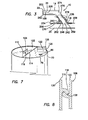
Figure 7 is a partial perspective view of the specimen container illustrating a latching mechanism; -
Figure 8 is a cross-sectional side elevational view of a detail of the latching mechanism; -
Figure 9 is a perspective view of the collection tube of a closed specimen collection system for blood and a receiving port for a centrally inserted venal catheter; -
Figure 10 is an enlarged perspective view of a specimen container illustrating a latching mechanism, sample port and aperture for attachment of the collection tube; -
Figure 11 is a cross-sectional detail view of the latching mechanism; -
Figure 12 is a perspective view of the closed specimen collection system for blood; -
Figure 13 is a perspective view of the back end of the specimen container of theFigure 12 embodiment illustrating details of a first embodiment of the piston of the specimen container; -
Figure 14 is a perspective view of the back end of the specimen container of theFigure 12 embodiment illustrating details of a second embodiment of the piston of the specimen container having two seals and a screw fitting for attachment of an activating rod to the piston; and -
Figure 15 is a perspective view of the front end of the specimen container illustrating the sample port and a screw fitting for attachment of the collection tube to the aperture. -
Figures 1-8 illustrate a closed specimen collection system forurine 10 providing the desired features that may be constructed from the following components. Aport tube 14 is provided. Theport tube 14 has afirst end 18, asecond end 22 and is rotatably attached at thefirst end 18 totubing 20 of aurinary drainage system 26 attached to an indwellingurinary catheter 30. Theport tube 14 has a one-way valve 34 located adjacent thesecond end 22. Thesecond end 22 is formed to fit sealably with a shapednozzle 38. - In a variant of the invention, as illustrated in
Figure 4 , acollection tube 42 is provided. Thecollection tube 42 has aproximal end 46 and adistal end 50 and has a shapednozzle 38 at theproximal end 46. The shapednozzle 38 is adapted to fit sealably into theport tube 14 at thesecond end 22 adjacent the one-way valve 34. Aprotective cover 54 is provided. Thecover 54 is attached to thecollection tube 42 adjacent theproximal end 46, has ahollow interior 58 and extends a firstpredetermined distance 62 past anouter end 66 of the shapednozzle 38. Aspecimen container 70 is provided. Thecontainer 70 has ahollow body 74, afront end 78 and aback end 82. Thefront end 78 has anaperture 86. Theaperture 86 is sized and shaped to attach to thedistal end 50 of thecollection tube 42. Theaperture 86 is sealable after removal of thedistal end 50 of thecollection tube 42 there from. Apiston 90 is provided. Thepiston 90 fits closely within thehollow body 74 and is attached to anactuating rod 94. When theport tube 14 is connected to thecollection tube 42, thecollection tube 42 is connected to thespecimen container 70 and theactuating rod 94 is moved away from thefront end 78 of thecontainer 70, urine (not shown) will flow into thespecimen container 70 in a sterile condition. - In another variant, the
collection tube 42 further includes aflexible portion 80 between theproximal end 46 and thedistal end 50. - In still another variant, as illustrated in
Figures 4 and7 , thefront end 78 of thespecimen container 70 includes arotating lid 102, thelid 102 sealably closing theaperture 86. - In yet another variant, as illustrated in
Figures 7 and 8 , alatching mechanism 106 is provided. Thelatching mechanism 106 controls rotation of thelid 102. - In a further variant, the
latching mechanism 106 further includes arotating portion 110. The rotatingportion 110 is affixed to aleading edge 114 of therotating lid 102 and has a projectingledge 118 located parallel to theleading edge 114. A fixedportion 122 is provided. The fixedportion 122 is attached to thefront end 78 of thespecimen container 70 and has a receivingslot 126 sized, shaped and located to mate frictionally with the projectingledge 118. When therotating lid 102 is positioned to seal theaperture 86, the projectingledge 118 will be secured within the receivingslot 126. - In still a further variant, the
latching mechanism 106 further includes aretracting tab 130 attached to therotating portion 110, theretracting tab 130 assisting in opening theaperture 86. - In yet a further variant, as illustrated in
Figures 4 and 5A , thepiston 90 further includes aseal 134. Theseal 134 has afront side 138 and aback side 142 and is sized and shaped to fit closely within thehollow body 74. Theseal 134 is located adjacent thefront end 78 of thespecimen container 70. Theseal 134 has a central receivingport 146 located at itscenter portion 150. Afirst end 154 of the actuatingrod 94 is sized and shaped to removably engage the central receivingport 146. When the actuatingrod 94 has withdrawn thepiston 90 toward theback end 82 of thespecimen container 70, the actuatingrod 94 is removed from the receivingport 146, theaperture 86 is sealed and thespecimen container 70 will contain a sterile urine sample. - In another variant of the invention, as illustrated in
Figures 5 and 5B , thepiston 90 further includes afirst seal 158. Thefirst seal 158 has afront side 162 and aback side 166 and is sized and shaped to fit closely within thehollow body 74. Thefirst seal 158 is located adjacent thefront end 78 of thespecimen container 70. Asecond seal 170 is provided. Thesecond seal 170 is sized and shaped to fit closely within thehollow body 74 and has a central receivingport 146 located at acenter portion 150 of thesecond seal 170. Thesecond seal 170 is spaced from theback side 166 of thefirst seal 158 and attached thereto at anouter surface 174 of the receivingport 146. Afirst end 154 of the actuatingrod 94 is sized and shaped to removably engage the central receivingport 146. When the actuatingrod 94 has withdrawn thepiston 90 toward theback end 82 of thespecimen container 70, the actuatingrod 94 is removed from the receivingport 146, theaperture 86 is sealed and thespecimen container 70 will contain a sterile urine sample 98. - In still another variant, as illustrated in
Figure 5B , the actuatingrod 94 has amale thread 178 at thefirst end 154 and the central receivingport 146 has a matingfemale thread 182. - In yet another variant, as illustrated in
Figure 6 , thedistal end 50 of thecollection tube 42 has anexternal thread 186 and theaperture 86 located at thefront end 78 of thespecimen container 70 has a matinginternal thread 190. - In a further variant, the
collection tube 42 further includes at least onelever 194 to assist in attaching thecollection tube 42 to theaperture 86 of thespecimen container 70. - In still a further variant, as illustrated in
Figures 1-4 , the one-way valve 34 further includes amembrane 198 formed ofpliable material 202, themembrane 198 has acentral opening 206, and theopening 206 is urged closed by an elastic nature of themembrane 198. - In yet a further variant, as illustrated in
Figure 1 , theport tube 14 is formed ofresilient material 210, is rotatably attached at anopening 214 in aside wall 218 of thetubing 20 of theurinary drainage system 26 and further includes first 222 and second 226 sealing gaskets located adjacent thefirst end 18. Thefirst sealing gasket 222 is located upon aninterior wall 230 of thetubing 20 and thesecond sealing gasket 226 is located upon anexterior wall 234 of thetubing 20. - In another variant of the invention, as illustrated in
Figure 3 , theport tube 14 further includes abase portion 238. Thebase portion 238 has ahollow core 242 with anattachment end 246 and a firstfitting end 250. Thebase portion 238 is attached at theattachment end 246 at an opening 254 in aside wall 258 of thetubing 20 of theurinary drainage system 26. Inner 262 and outer 266 sealing gaskets are located adjacent theattachment end 246. Theinner sealing gasket 262 is located upon aninterior wall 230 of thetubing 20. Theouter sealing gasket 266 is located upon anexterior wall 234 of thetubing 20. Atube portion 270 is provided. Thetube portion 270 has ahollow interior 274, a secondfitting end 278 and avalve end 282. The secondfitting end 278 of thetube portion 270 is rotatably attached to the firstfitting end 250 of thebase portion 238. Thetube portion 270 has a one-way valve 34 located adjacent thevalve end 282. - A closed specimen collection system for
blood samples 300, as illustrated inFigures 9 and 12 , may be constructed from the following components. Acollection tube 304 is provided. Thecollection tube 304 has aproximal end 308 and adistal end 312 and has a shapednozzle 316 at theproximal end 308. The shapednozzle 316 is adapted to fit sealably into aport 320 connected to a centrally insertedvenal catheter 324. Aprotective cover 328 is provided. Thecover 328 is attached to thecollection tube 304 adjacent theproximal end 308, has ahollow interior 332 and extends outwardly from abase 336 of the shapednozzle 316 for a firstpredetermined distance 340. Thecover 328 has an internal,female thread 344. Thefemale thread 344 mates to amale thread 348 on theport 320. Aspecimen container 352 is provided. Thecontainer 352 has ahollow body 356, afront end 360 and aback end 364. Thefront end 360 has anaperture 368. Theaperture 368 is sized and shaped to attach to thedistal end 312 of thecollection tube 304. Theaperture 368 is sealable after removal of thedistal end 312 of thecollection tube 304. Apiston 372 is provided. Thepiston 372 fits closely within thehollow body 356 and is attached to anactuating rod 376. When theport 320 is connected to thecollection tube 304, thecollection tube 304 is connected to thespecimen container 352 and theactuating rod 376 is moved away from thefront end 360 of thecontainer 352, blood will flow into thespecimen container 352 in a sterile condition. - In a variant of the invention, the
protective cover 328 further includes at least onelever 380 to assist in attaching thecover 328 to theport 320. - In another variant, as illustrated in
Figures 10 and12 , thefront end 360 of thespecimen container 352 further includes asample opening 384. Theopening 384 is sealed with arubber membrane 388 adapted to accommodate needle penetration. - In yet another variant, the
front end 360 of thespecimen container 352 includes arotating lid 396. Thelid 396 closes and seals theaperture 368. - In a further variant, the
lid 396 for thespecimen container 352 further includes alatching mechanism 400. Thelatching mechanism 400 controls rotation of thelid 396. - In still a further variant, as illustrated in
Figures 10 and 11 , thelatching mechanism 400 further includes arotating portion 404. The rotatingportion 404 is affixed to aleading edge 408 of therotating lid 396 and has a projectingledge 410 located parallel to theleading edge 408. A fixedportion 412 is provided. The fixedportion 412 is affixed to thefront end 360 of thespecimen container 352. The fixedportion 412 has a receivingslot 416 sized, shaped and located to mate frictionally with the projectingledge 408. When therotating lid 396 is positioned to seal theaperture 368, the projectingledge 408 will be secured within the receivingslot 416. - In yet a further variant, the
latching mechanism 400 further includes aretracting tab 420 attached to therotating portion 404, theretracting tab 420 assists in opening theaperture 368. - In another variant of the invention, as illustrated in
Figure 13 , thepiston 372 further includes aseal 424. Theseal 424 has afront side 428 and aback side 432 and is sized and shaped to fit closely within thehollow body 356. Theseal 424 is located adjacent thefront end 360 of thespecimen container 352. Theseal 424, has a central receivingport 436 located at acenter portion 440 of theseal 424. Afirst end 444 of theactuating rod 376 is sized and shaped to removably engage the central receivingport 436. When theactuating rod 376 has withdrawn thepiston 372 toward theback end 364 of thespecimen container 352, theactuating rod 376 is removed from the receivingport 436, theaperture 368 is sealed and thespecimen container 352 will contain a sterile blood sample. - In still another variant, as illustrated in
Figure 14 , thepiston 372 further includes afirst seal 448. Thefirst seal 448 has afront side 452 and aback side 456 and is sized and shaped to fit closely within thehollow body 356. Thefirst seal 448 is located adjacent thefront end 360 of thespecimen container 352. Asecond seal 460 is provided. Thesecond seal 460 is sized and shaped to fit closely within thehollow body 356 and has a central receivingport 464 penetrating acenter portion 468 of thesecond seal 460. Thesecond seal 460 is spaced from theback side 456 of thefirst seal 448 and attached to it at anouter surface 470 of the receivingport 464. Afirst end 472 of theactuating rod 376 is sized and shaped to removably engage the central receivingport 464. When theactuating rod 376 has withdrawn thepiston 372 toward theback end 364 of thespecimen container 352, theactuating rod 376 is removed from the receivingport 464, theaperture 368 is sealed and thespecimen container 352 will contain a sterile blood sample. - In yet another variant, the
actuating rod 376 has amale thread 476 at thefirst end 472 and the central receivingport 464 has a matingfemale thread 480. - In a further variant, as illustrated in
Figure 15 , thedistal end 312 of thecollection tube 304 has anexternal thread 484 and theaperture 368 located at thefront end 360 of thespecimen container 352 has a matinginternal thread 488. - In a final variant of the invention the
specimen container 352 further includes asterile culture medium 496. - The closed
specimen collection systems
Claims (12)
- A closed specimen collection system, comprising:a collection tube, said collection tube having a proximal end and a distal end and having a shaped nozzle at said proximal end, said shaped nozzle being adapted to fit sealably into a port connected to a centrally inserted venal catheter;a protective cover, said cover being attached to said collection tube adjacent said proximal end, having a hollow interior and extending outwardly from a base of said shaped nozzle a first predetermined distance, said cover having an internal, female thread, said female thread mating to a male thread on said port;a specimen container, said container having a hollow body, a front end and a back end, said front end having an aperture, said aperture being sized and shaped to attach to said distal end of said collection tube, said aperture being sealable after removal of said distal end of said collection tube; anda piston, said piston fitting closely within said hollow body and being attached to an actuating rod,whereby, when said port is connected to said collection tube, said collection tube is connected to said specimen container and said actuating rod is moved away from said front end of said container, blood will flow into said specimen container in a sterile condition.
- The closed specimen collection system, as described in Claim 1, wherein said protective cover further comprises at least one lever to assist in attaching said cover to said port.
- The closed specimen collection system, as described in Claim 1, wherein said front end of said specimen container further comprises a sample opening, said opening being sealed with a rubber membrane, said membrane adapted to accommodate needle penetration.
- The closed specimen collection system, as described in Claim 1, wherein said front end of said specimen container includes a rotating lid, said lid sealably closing said aperture.
- The closed specimen collection system, as described in Claim 4, further comprising a latching mechanism, said latching mechanism controlling rotation of said lid.
- The closed specimen collection system, as described in Claim 5, wherein said latching mechanism further comprises:a rotating portion, said rotating portion affixed to a leading edge of said rotating lid and having a projecting ledge disposed parallel to said leading edge; anda fixed portion, said fixed portion affixed to said front end of said specimen container, having a receiving slot sized, shaped and disposed to mate frictionally with said projecting ledge,whereby, when said rotating lid is positioned to seal said aperture, said projecting ledge will be secured within said receiving slot.
- The closed specimen collection system, as described in Claim 6, wherein said latching mechanism further comprises a retracting tab attached to said rotating portion, said retracting tab assisting in opening said aperture.
- The closed specimen collection system, as described in Claim 1, wherein said piston further comprises:a seal, said seal having a front side and a back side and being sized and shaped to fit closely within said hollow body and disposed adjacent said front end of said specimen container, said seal, having a central receiving port disposed at a center portion thereof, a first end of said actuating rod be sized and shaped to removably engage said central receiving port,whereby, when said actuating rod has withdrawn said piston toward said back end of said specimen container, said actuating rod is removed from said receiving port, said aperture is sealed and said specimen container will contain a sterile blood sample.
- The closed specimen collection system, as described in Claim 1, wherein said piston further comprises:a first seal, said first seal having a front side and a back side and being sized and shaped to fit closely within said hollow body and disposed adjacent said front end of said specimen container; anda second seal, said second seal being sized and shaped to fit closely within said hollow body and having a central receiving port penetrating a center portion of said second seal, said second seal being spaced from said back side of said first seal and attached thereto at an outer surface of said receiving port a first end of said actuating rod being sized and shaped to removably engage said central receiving port,whereby, when said actuating rod has withdrawn said piston toward said back end of said specimen container, said actuating rod is removed from said receiving port, said aperture is sealed and said specimen container will contain a sterile blood sample.
- The closed specimen collection system, as described in Claim 8, wherein said actuating rod has a male thread at said first end and said central receiving port has a mating female thread.
- The closed specimen collection system, as described in Claim 1, wherein said distal end of said collection tube has an external thread and said aperture disposed at said front end of said specimen container has a mating internal thread.
- The closed specimen collection system, as described in Claim 1, wherein said specimen container further comprises a sterile culture medium.
Applications Claiming Priority (3)
| Application Number | Priority Date | Filing Date | Title |
|---|---|---|---|
| US11/858,073 US7875021B2 (en) | 2007-09-19 | 2007-09-19 | Closed specimen collection system |
| US12/209,025 US8246552B2 (en) | 2007-09-19 | 2008-09-11 | Closed specimen collection system |
| EP08799526.2A EP2247859B1 (en) | 2007-09-19 | 2008-09-12 | Closed specimen collection system |
Related Parent Applications (1)
| Application Number | Title | Priority Date | Filing Date |
|---|---|---|---|
| EP08799526.2A Division EP2247859B1 (en) | 2007-09-19 | 2008-09-12 | Closed specimen collection system |
Publications (2)
| Publication Number | Publication Date |
|---|---|
| EP2803868A1 true EP2803868A1 (en) | 2014-11-19 |
| EP2803868B1 EP2803868B1 (en) | 2016-03-23 |
Family
ID=40455328
Family Applications (2)
| Application Number | Title | Priority Date | Filing Date |
|---|---|---|---|
| EP14176599.0A Active EP2803868B1 (en) | 2007-09-19 | 2008-09-12 | Closed specimen collection system |
| EP08799526.2A Not-in-force EP2247859B1 (en) | 2007-09-19 | 2008-09-12 | Closed specimen collection system |
Family Applications After (1)
| Application Number | Title | Priority Date | Filing Date |
|---|---|---|---|
| EP08799526.2A Not-in-force EP2247859B1 (en) | 2007-09-19 | 2008-09-12 | Closed specimen collection system |
Country Status (5)
| Country | Link |
|---|---|
| US (1) | US8246552B2 (en) |
| EP (2) | EP2803868B1 (en) |
| AU (1) | AU2008302455B2 (en) |
| CA (1) | CA2699883C (en) |
| WO (1) | WO2009039044A1 (en) |
Cited By (1)
| Publication number | Priority date | Publication date | Assignee | Title |
|---|---|---|---|---|
| WO2022033615A1 (en) * | 2020-08-14 | 2022-02-17 | Forschungszentrum Jülich GmbH | Device for a sterile liquid transfer |
Families Citing this family (4)
| Publication number | Priority date | Publication date | Assignee | Title |
|---|---|---|---|---|
| MY149078A (en) * | 2009-12-07 | 2013-07-15 | Ratnarajah A L Vemalarajah | A specimen collecting and testing apparatus |
| CN105711301A (en) * | 2016-04-01 | 2016-06-29 | 陈庭 | Universal ruler for study |
| US10633631B1 (en) | 2017-03-01 | 2020-04-28 | Gerald R. Harris | Platelet rich plasma preparation system and devices |
| DE102019121841A1 (en) * | 2019-08-13 | 2021-02-18 | B.Braun Avitum Ag | Medical fluid sampling system with a sample / collection container with culture medium or test field and culture medium preparation procedure |
Citations (11)
| Publication number | Priority date | Publication date | Assignee | Title |
|---|---|---|---|---|
| US4702740A (en) | 1982-07-21 | 1987-10-27 | The Kendall Company | Collection system with valve members |
| US4723950A (en) | 1984-12-12 | 1988-02-09 | C. R. Bard, Inc. | Urine drainage bag outlet with barrier against microbial infection |
| US4784654A (en) | 1982-11-16 | 1988-11-15 | Illinois Tool Works, Inc. | Urinary collection system and improved female urinary appliance |
| EP0462814A1 (en) * | 1990-06-19 | 1991-12-27 | Lawrence A. Lynn | Blood withdrawal apparatus |
| US5158554A (en) * | 1988-01-25 | 1992-10-27 | Baxter International Inc. | Pre-slit injection site and associated cannula |
| US5176665A (en) | 1991-01-18 | 1993-01-05 | Alza Corporation | Antimicrobial device for urine drainage container |
| EP0592391A1 (en) * | 1989-04-10 | 1994-04-20 | Baxter Int | Pre-slit injection site and tapered cannula. |
| US6045542A (en) | 1999-01-13 | 2000-04-04 | Cawood Family Limited Partnership | Urine collection device |
| WO2000071196A1 (en) * | 1999-05-21 | 2000-11-30 | Micro Therapeutics, Inc. | Interface needle and method for creating a blunt interface between delivered liquids |
| EP1366711A1 (en) * | 2002-05-31 | 2003-12-03 | KABE Labortechnik Gesellschaft mit beschränkter Haftung | Adapter for a blood sampling device |
| US6793651B1 (en) | 2000-02-23 | 2004-09-21 | Icu Medical, Inc. | Urinary catheter system with a releasable connector |
Family Cites Families (45)
| Publication number | Priority date | Publication date | Assignee | Title |
|---|---|---|---|---|
| US2871857A (en) * | 1957-06-12 | 1959-02-03 | Lee Barry Lab Inc | Hypodermic and body fluids sampling syringes |
| US2992974A (en) * | 1960-04-04 | 1961-07-18 | Allan S Belcove | Biological testing device |
| US3579303A (en) | 1968-03-06 | 1971-05-18 | Donald E Pickering | System for handling specimens and other substances in medicine and physical sciences |
| US3894540A (en) | 1973-10-09 | 1975-07-15 | Bonner F J Jun | Catheter |
| US4136680A (en) * | 1976-06-04 | 1979-01-30 | Transmed Corp. | Self-contained apparatus for collection and maintenance of medical specimen and methods of using same |
| US4068659A (en) | 1976-07-12 | 1978-01-17 | Deseret Pharmaceutical Co., Inc. | Catheter placement assembly |
| US4190059A (en) | 1978-10-25 | 1980-02-26 | Colonics Diversified, Inc. | Apparatus for colonic lavage and specimen collection |
| US4327723A (en) | 1980-05-13 | 1982-05-04 | Arrow International, Inc. | Catheter shield |
| US4515592A (en) | 1980-05-13 | 1985-05-07 | Arrow International, Inc. | Catheter shield |
| JPS57190567A (en) * | 1981-05-20 | 1982-11-24 | Terumo Corp | Blood sampler with air removing and shielding mechanism |
| GB8509301D0 (en) | 1985-04-11 | 1985-05-15 | Clinical Products Dev Ltd | Device for surgical procedures |
| US4972844A (en) | 1985-05-06 | 1990-11-27 | The Kendall Company | Sampling chamber assembly for in-line measurements of fluid within a collection system |
| CA1264275A (en) | 1985-09-04 | 1990-01-09 | Wadley Technologies, Inc. | Stabilization of specimens for microbial analysis |
| US4981469A (en) * | 1988-04-18 | 1991-01-01 | Dij Catheter Corp. | Septum adapter assembly and external needle adapter fitting |
| US4966585A (en) * | 1988-05-31 | 1990-10-30 | Gangemi Ronald J | Infusion apparatus |
| US4932938A (en) | 1989-05-05 | 1990-06-12 | Medical Engineering Corporation | Urethral indwelling catheter with incontinence control |
| US4941580A (en) * | 1989-05-26 | 1990-07-17 | Sunbeam Plastics Corporation | Dispensing closure |
| US5670111A (en) | 1990-01-10 | 1997-09-23 | Rochester Medical Corporation | Method of shaping structures with an overcoat layer including female urinary catheter |
| US5096454A (en) | 1990-08-16 | 1992-03-17 | Samples Charles R | Method of catheterization and bladder drainage |
| US5176655A (en) * | 1990-11-08 | 1993-01-05 | Mbo Laboratories, Inc. | Disposable medical needle and catheter placement assembly having full safety enclosure means |
| US5140999A (en) | 1991-09-30 | 1992-08-25 | Primed International Corp. | Urinary incontinence valve device |
| US5373684A (en) * | 1992-12-14 | 1994-12-20 | Mallinckrodt Medical, Inc. | Process and apparatus used in producing prefilled, sterile delivery devices |
| CA2116724A1 (en) | 1993-03-12 | 1994-09-13 | Richard A. Gambale | Windowed catheter and method of use |
| US6827705B2 (en) | 1993-03-19 | 2004-12-07 | Venetec International, Inc. | Catheter anchoring system |
| US5365960A (en) | 1993-04-05 | 1994-11-22 | Verteq, Inc. | Megasonic transducer assembly |
| US5511557A (en) | 1993-11-09 | 1996-04-30 | Hazard; James T. | Urine specimen collection device |
| US5536258A (en) * | 1994-02-14 | 1996-07-16 | Fresenius Usa, Inc. | Antibacterial medical tubing connector |
| US5979475A (en) | 1994-04-28 | 1999-11-09 | Hitachi, Ltd. | Specimen holding method and fluid treatment method of specimen surface and systems therefor |
| US5595187A (en) * | 1994-06-20 | 1997-01-21 | Urocath Corporation | Analytical specimen cup system and method |
| US6743198B1 (en) | 1995-03-20 | 2004-06-01 | Conticare Medical, Inc. | Self-cleansing bladder drainage device |
| US6315145B1 (en) * | 1995-07-13 | 2001-11-13 | Sticksafe Llc | Lid for a specimen container that is adapted to minimize spills and leaks |
| US5637091A (en) | 1995-08-31 | 1997-06-10 | Hakky; Said I. | Collapsible catheter |
| US5785694A (en) | 1995-12-01 | 1998-07-28 | Cohen; Kenneth L. | Internal urinary catheter |
| EP0893137B1 (en) | 1997-07-22 | 2004-03-31 | Terumo Kabushiki Kaisha | Assembly for an indwelling catheter and method of making it |
| JP3734962B2 (en) | 1997-11-10 | 2006-01-11 | テルモ株式会社 | Indwelling catheter |
| US6235010B1 (en) | 1999-08-06 | 2001-05-22 | Becton Dickinson And Company | Closed system specimen collection container |
| US6511459B1 (en) * | 2000-09-29 | 2003-01-28 | Mallinckrodt Inc. | Syringe plunger having an improved sealing ability |
| US6732875B2 (en) | 2001-08-06 | 2004-05-11 | Solo Cup Company | Reclosable container lid |
| US6830563B1 (en) | 2001-08-24 | 2004-12-14 | Scott Singer | Syringe tip providing nonlaminar spiral flow and method of use for flushing catheters |
| US6820506B2 (en) * | 2002-03-27 | 2004-11-23 | 3M Innovative Properties Company | Multi-chambered pump-valve device |
| US8353895B2 (en) * | 2002-04-16 | 2013-01-15 | Ronald D Russo | Closed system irrigation connector for urinary catheters |
| US6783522B2 (en) | 2002-09-09 | 2004-08-31 | Angel Medical Systems, Inc. | Implantable catheter having an improved check valve |
| US20040181192A1 (en) * | 2003-03-11 | 2004-09-16 | Cuppy Michael John | Vascular access device and method of using same |
| US6913244B1 (en) | 2003-05-02 | 2005-07-05 | Gordon Edgar Atkinson | Urinary slide valve |
| US20060185448A1 (en) * | 2005-02-23 | 2006-08-24 | Cytyc Corporation | Biological specimen container cap with actuated access |
-
2008
- 2008-09-11 US US12/209,025 patent/US8246552B2/en active Active
- 2008-09-12 WO PCT/US2008/076277 patent/WO2009039044A1/en active Application Filing
- 2008-09-12 AU AU2008302455A patent/AU2008302455B2/en active Active
- 2008-09-12 EP EP14176599.0A patent/EP2803868B1/en active Active
- 2008-09-12 EP EP08799526.2A patent/EP2247859B1/en not_active Not-in-force
- 2008-09-12 CA CA2699883A patent/CA2699883C/en active Active
Patent Citations (11)
| Publication number | Priority date | Publication date | Assignee | Title |
|---|---|---|---|---|
| US4702740A (en) | 1982-07-21 | 1987-10-27 | The Kendall Company | Collection system with valve members |
| US4784654A (en) | 1982-11-16 | 1988-11-15 | Illinois Tool Works, Inc. | Urinary collection system and improved female urinary appliance |
| US4723950A (en) | 1984-12-12 | 1988-02-09 | C. R. Bard, Inc. | Urine drainage bag outlet with barrier against microbial infection |
| US5158554A (en) * | 1988-01-25 | 1992-10-27 | Baxter International Inc. | Pre-slit injection site and associated cannula |
| EP0592391A1 (en) * | 1989-04-10 | 1994-04-20 | Baxter Int | Pre-slit injection site and tapered cannula. |
| EP0462814A1 (en) * | 1990-06-19 | 1991-12-27 | Lawrence A. Lynn | Blood withdrawal apparatus |
| US5176665A (en) | 1991-01-18 | 1993-01-05 | Alza Corporation | Antimicrobial device for urine drainage container |
| US6045542A (en) | 1999-01-13 | 2000-04-04 | Cawood Family Limited Partnership | Urine collection device |
| WO2000071196A1 (en) * | 1999-05-21 | 2000-11-30 | Micro Therapeutics, Inc. | Interface needle and method for creating a blunt interface between delivered liquids |
| US6793651B1 (en) | 2000-02-23 | 2004-09-21 | Icu Medical, Inc. | Urinary catheter system with a releasable connector |
| EP1366711A1 (en) * | 2002-05-31 | 2003-12-03 | KABE Labortechnik Gesellschaft mit beschränkter Haftung | Adapter for a blood sampling device |
Cited By (1)
| Publication number | Priority date | Publication date | Assignee | Title |
|---|---|---|---|---|
| WO2022033615A1 (en) * | 2020-08-14 | 2022-02-17 | Forschungszentrum Jülich GmbH | Device for a sterile liquid transfer |
Also Published As
| Publication number | Publication date |
|---|---|
| EP2803868B1 (en) | 2016-03-23 |
| CA2699883A1 (en) | 2009-03-26 |
| WO2009039044A1 (en) | 2009-03-26 |
| AU2008302455A1 (en) | 2009-03-26 |
| US8246552B2 (en) | 2012-08-21 |
| EP2247859A4 (en) | 2013-04-10 |
| EP2247859B1 (en) | 2014-07-16 |
| US20090076414A1 (en) | 2009-03-19 |
| AU2008302455B2 (en) | 2013-09-12 |
| CA2699883C (en) | 2015-04-07 |
| EP2247859A1 (en) | 2010-11-10 |
Similar Documents
| Publication | Publication Date | Title |
|---|---|---|
| US6793651B1 (en) | Urinary catheter system with a releasable connector | |
| JP2670290B2 (en) | Cassette assembly | |
| US9687628B2 (en) | Systems and methods for removal of urine | |
| US7713246B2 (en) | Automatic valve | |
| EP1825835B1 (en) | Urine collection system with needleless sampling port | |
| EP0232600B1 (en) | Apparatus for draining fluid from a body cavity | |
| US20050010189A1 (en) | Body fluid collection apparatus | |
| EP2803868B1 (en) | Closed specimen collection system | |
| GB2032401A (en) | Sterile air vent | |
| US7875021B2 (en) | Closed specimen collection system | |
| JPH0374584B2 (en) | ||
| AU2013276103A1 (en) | Novel tubing valve and uses thereof | |
| DK2345450T3 (en) | Application set, comprising an applicator and a hose-sheathing to the applicator, and implantationsinstrumenter | |
| CN209826787U (en) | Integrated sterile negative pressure urine collector for urine culture of indwelling ureter patient | |
| EP3349819A1 (en) | Fully disposable suction and irrigation apparatus for use in medical procedures | |
| CN201701582U (en) | Automatic transfusion sealing dripping stop device | |
| CN109481761A (en) | A kind of operation attraction configurator and its method |
Legal Events
| Date | Code | Title | Description |
|---|---|---|---|
| PUAI | Public reference made under article 153(3) epc to a published international application that has entered the european phase |
Free format text: ORIGINAL CODE: 0009012 |
|
| 17P | Request for examination filed |
Effective date: 20140710 |
|
| AC | Divisional application: reference to earlier application |
Ref document number: 2247859 Country of ref document: EP Kind code of ref document: P |
|
| AK | Designated contracting states |
Kind code of ref document: A1 Designated state(s): AT BE BG CH CY CZ DE DK EE ES FI FR GB GR HR HU IE IS IT LI LT LU LV MC MT NL NO PL PT RO SE SI SK TR |
|
| GRAP | Despatch of communication of intention to grant a patent |
Free format text: ORIGINAL CODE: EPIDOSNIGR1 |
|
| R17P | Request for examination filed (corrected) |
Effective date: 20150519 |
|
| RBV | Designated contracting states (corrected) |
Designated state(s): AT BE BG CH CY CZ DE DK EE ES FI FR GB GR HR HU IE IS IT LI LT LU LV MC MT NL NO PL PT RO SE SI SK TR |
|
| INTG | Intention to grant announced |
Effective date: 20150701 |
|
| GRAS | Grant fee paid |
Free format text: ORIGINAL CODE: EPIDOSNIGR3 |
|
| GRAA | (expected) grant |
Free format text: ORIGINAL CODE: 0009210 |
|
| AC | Divisional application: reference to earlier application |
Ref document number: 2247859 Country of ref document: EP Kind code of ref document: P |
|
| AK | Designated contracting states |
Kind code of ref document: B1 Designated state(s): AT BE BG CH CY CZ DE DK EE ES FI FR GB GR HR HU IE IS IT LI LT LU LV MC MT NL NO PL PT RO SE SI SK TR |
|
| REG | Reference to a national code |
Ref country code: GB Ref legal event code: FG4D |
|
| REG | Reference to a national code |
Ref country code: CH Ref legal event code: EP |
|
| REG | Reference to a national code |
Ref country code: AT Ref legal event code: REF Ref document number: 783452 Country of ref document: AT Kind code of ref document: T Effective date: 20160415 |
|
| REG | Reference to a national code |
Ref country code: IE Ref legal event code: FG4D |
|
| REG | Reference to a national code |
Ref country code: DE Ref legal event code: R096 Ref document number: 602008043129 Country of ref document: DE |
|
| REG | Reference to a national code |
Ref country code: SE Ref legal event code: TRGR |
|
| REG | Reference to a national code |
Ref country code: LT Ref legal event code: MG4D |
|
| PG25 | Lapsed in a contracting state [announced via postgrant information from national office to epo] |
Ref country code: NO Free format text: LAPSE BECAUSE OF FAILURE TO SUBMIT A TRANSLATION OF THE DESCRIPTION OR TO PAY THE FEE WITHIN THE PRESCRIBED TIME-LIMIT Effective date: 20160623 Ref country code: HR Free format text: LAPSE BECAUSE OF FAILURE TO SUBMIT A TRANSLATION OF THE DESCRIPTION OR TO PAY THE FEE WITHIN THE PRESCRIBED TIME-LIMIT Effective date: 20160323 Ref country code: GR Free format text: LAPSE BECAUSE OF FAILURE TO SUBMIT A TRANSLATION OF THE DESCRIPTION OR TO PAY THE FEE WITHIN THE PRESCRIBED TIME-LIMIT Effective date: 20160624 Ref country code: FI Free format text: LAPSE BECAUSE OF FAILURE TO SUBMIT A TRANSLATION OF THE DESCRIPTION OR TO PAY THE FEE WITHIN THE PRESCRIBED TIME-LIMIT Effective date: 20160323 |
|
| REG | Reference to a national code |
Ref country code: NL Ref legal event code: FP |
|
| PG25 | Lapsed in a contracting state [announced via postgrant information from national office to epo] |
Ref country code: LT Free format text: LAPSE BECAUSE OF FAILURE TO SUBMIT A TRANSLATION OF THE DESCRIPTION OR TO PAY THE FEE WITHIN THE PRESCRIBED TIME-LIMIT Effective date: 20160323 Ref country code: LV Free format text: LAPSE BECAUSE OF FAILURE TO SUBMIT A TRANSLATION OF THE DESCRIPTION OR TO PAY THE FEE WITHIN THE PRESCRIBED TIME-LIMIT Effective date: 20160323 |
|
| REG | Reference to a national code |
Ref country code: FR Ref legal event code: PLFP Year of fee payment: 9 |
|
| PG25 | Lapsed in a contracting state [announced via postgrant information from national office to epo] |
Ref country code: PL Free format text: LAPSE BECAUSE OF FAILURE TO SUBMIT A TRANSLATION OF THE DESCRIPTION OR TO PAY THE FEE WITHIN THE PRESCRIBED TIME-LIMIT Effective date: 20160323 Ref country code: EE Free format text: LAPSE BECAUSE OF FAILURE TO SUBMIT A TRANSLATION OF THE DESCRIPTION OR TO PAY THE FEE WITHIN THE PRESCRIBED TIME-LIMIT Effective date: 20160323 Ref country code: IS Free format text: LAPSE BECAUSE OF FAILURE TO SUBMIT A TRANSLATION OF THE DESCRIPTION OR TO PAY THE FEE WITHIN THE PRESCRIBED TIME-LIMIT Effective date: 20160723 |
|
| PGFP | Annual fee paid to national office [announced via postgrant information from national office to epo] |
Ref country code: NL Payment date: 20160926 Year of fee payment: 9 Ref country code: IE Payment date: 20160923 Year of fee payment: 9 |
|
| PG25 | Lapsed in a contracting state [announced via postgrant information from national office to epo] |
Ref country code: RO Free format text: LAPSE BECAUSE OF FAILURE TO SUBMIT A TRANSLATION OF THE DESCRIPTION OR TO PAY THE FEE WITHIN THE PRESCRIBED TIME-LIMIT Effective date: 20160323 Ref country code: ES Free format text: LAPSE BECAUSE OF FAILURE TO SUBMIT A TRANSLATION OF THE DESCRIPTION OR TO PAY THE FEE WITHIN THE PRESCRIBED TIME-LIMIT Effective date: 20160323 Ref country code: CZ Free format text: LAPSE BECAUSE OF FAILURE TO SUBMIT A TRANSLATION OF THE DESCRIPTION OR TO PAY THE FEE WITHIN THE PRESCRIBED TIME-LIMIT Effective date: 20160323 Ref country code: PT Free format text: LAPSE BECAUSE OF FAILURE TO SUBMIT A TRANSLATION OF THE DESCRIPTION OR TO PAY THE FEE WITHIN THE PRESCRIBED TIME-LIMIT Effective date: 20160725 Ref country code: SK Free format text: LAPSE BECAUSE OF FAILURE TO SUBMIT A TRANSLATION OF THE DESCRIPTION OR TO PAY THE FEE WITHIN THE PRESCRIBED TIME-LIMIT Effective date: 20160323 |
|
| PGFP | Annual fee paid to national office [announced via postgrant information from national office to epo] |
Ref country code: AT Payment date: 20160921 Year of fee payment: 9 Ref country code: FR Payment date: 20160926 Year of fee payment: 9 |
|
| PG25 | Lapsed in a contracting state [announced via postgrant information from national office to epo] |
Ref country code: IT Free format text: LAPSE BECAUSE OF FAILURE TO SUBMIT A TRANSLATION OF THE DESCRIPTION OR TO PAY THE FEE WITHIN THE PRESCRIBED TIME-LIMIT Effective date: 20160323 Ref country code: BE Free format text: LAPSE BECAUSE OF FAILURE TO SUBMIT A TRANSLATION OF THE DESCRIPTION OR TO PAY THE FEE WITHIN THE PRESCRIBED TIME-LIMIT Effective date: 20160323 |
|
| REG | Reference to a national code |
Ref country code: DE Ref legal event code: R097 Ref document number: 602008043129 Country of ref document: DE |
|
| PLBE | No opposition filed within time limit |
Free format text: ORIGINAL CODE: 0009261 |
|
| STAA | Information on the status of an ep patent application or granted ep patent |
Free format text: STATUS: NO OPPOSITION FILED WITHIN TIME LIMIT |
|
| PG25 | Lapsed in a contracting state [announced via postgrant information from national office to epo] |
Ref country code: DK Free format text: LAPSE BECAUSE OF FAILURE TO SUBMIT A TRANSLATION OF THE DESCRIPTION OR TO PAY THE FEE WITHIN THE PRESCRIBED TIME-LIMIT Effective date: 20160323 |
|
| PGFP | Annual fee paid to national office [announced via postgrant information from national office to epo] |
Ref country code: DE Payment date: 20160928 Year of fee payment: 9 |
|
| PG25 | Lapsed in a contracting state [announced via postgrant information from national office to epo] |
Ref country code: BG Free format text: LAPSE BECAUSE OF FAILURE TO SUBMIT A TRANSLATION OF THE DESCRIPTION OR TO PAY THE FEE WITHIN THE PRESCRIBED TIME-LIMIT Effective date: 20160623 |
|
| 26N | No opposition filed |
Effective date: 20170102 |
|
| PG25 | Lapsed in a contracting state [announced via postgrant information from national office to epo] |
Ref country code: MC Free format text: LAPSE BECAUSE OF FAILURE TO SUBMIT A TRANSLATION OF THE DESCRIPTION OR TO PAY THE FEE WITHIN THE PRESCRIBED TIME-LIMIT Effective date: 20160323 |
|
| PG25 | Lapsed in a contracting state [announced via postgrant information from national office to epo] |
Ref country code: SI Free format text: LAPSE BECAUSE OF FAILURE TO SUBMIT A TRANSLATION OF THE DESCRIPTION OR TO PAY THE FEE WITHIN THE PRESCRIBED TIME-LIMIT Effective date: 20160323 |
|
| PG25 | Lapsed in a contracting state [announced via postgrant information from national office to epo] |
Ref country code: LU Free format text: LAPSE BECAUSE OF NON-PAYMENT OF DUE FEES Effective date: 20160912 |
|
| REG | Reference to a national code |
Ref country code: DE Ref legal event code: R119 Ref document number: 602008043129 Country of ref document: DE |
|
| REG | Reference to a national code |
Ref country code: NL Ref legal event code: MM Effective date: 20171001 |
|
| REG | Reference to a national code |
Ref country code: AT Ref legal event code: MM01 Ref document number: 783452 Country of ref document: AT Kind code of ref document: T Effective date: 20170912 |
|
| PG25 | Lapsed in a contracting state [announced via postgrant information from national office to epo] |
Ref country code: HU Free format text: LAPSE BECAUSE OF FAILURE TO SUBMIT A TRANSLATION OF THE DESCRIPTION OR TO PAY THE FEE WITHIN THE PRESCRIBED TIME-LIMIT; INVALID AB INITIO Effective date: 20080912 |
|
| REG | Reference to a national code |
Ref country code: IE Ref legal event code: MM4A |
|
| PG25 | Lapsed in a contracting state [announced via postgrant information from national office to epo] |
Ref country code: NL Free format text: LAPSE BECAUSE OF NON-PAYMENT OF DUE FEES Effective date: 20171001 Ref country code: MT Free format text: LAPSE BECAUSE OF NON-PAYMENT OF DUE FEES Effective date: 20160930 Ref country code: CY Free format text: LAPSE BECAUSE OF FAILURE TO SUBMIT A TRANSLATION OF THE DESCRIPTION OR TO PAY THE FEE WITHIN THE PRESCRIBED TIME-LIMIT Effective date: 20160323 |
|
| REG | Reference to a national code |
Ref country code: FR Ref legal event code: ST Effective date: 20180531 |
|
| PG25 | Lapsed in a contracting state [announced via postgrant information from national office to epo] |
Ref country code: DE Free format text: LAPSE BECAUSE OF NON-PAYMENT OF DUE FEES Effective date: 20180404 Ref country code: IE Free format text: LAPSE BECAUSE OF NON-PAYMENT OF DUE FEES Effective date: 20170912 |
|
| PG25 | Lapsed in a contracting state [announced via postgrant information from national office to epo] |
Ref country code: FR Free format text: LAPSE BECAUSE OF NON-PAYMENT OF DUE FEES Effective date: 20171002 Ref country code: AT Free format text: LAPSE BECAUSE OF NON-PAYMENT OF DUE FEES Effective date: 20170912 |
|
| PG25 | Lapsed in a contracting state [announced via postgrant information from national office to epo] |
Ref country code: TR Free format text: LAPSE BECAUSE OF FAILURE TO SUBMIT A TRANSLATION OF THE DESCRIPTION OR TO PAY THE FEE WITHIN THE PRESCRIBED TIME-LIMIT Effective date: 20160323 |
|
| PGFP | Annual fee paid to national office [announced via postgrant information from national office to epo] |
Ref country code: GB Payment date: 20231018 Year of fee payment: 16 |
|
| PGFP | Annual fee paid to national office [announced via postgrant information from national office to epo] |
Ref country code: SE Payment date: 20231018 Year of fee payment: 16 Ref country code: CH Payment date: 20231025 Year of fee payment: 16 |