EP2805633B1 - Trays made of conductive plastic and device and method for automatically unloading trays filled with rod-shaped articles - Google Patents
Trays made of conductive plastic and device and method for automatically unloading trays filled with rod-shaped articles Download PDFInfo
- Publication number
- EP2805633B1 EP2805633B1 EP14164574.7A EP14164574A EP2805633B1 EP 2805633 B1 EP2805633 B1 EP 2805633B1 EP 14164574 A EP14164574 A EP 14164574A EP 2805633 B1 EP2805633 B1 EP 2805633B1
- Authority
- EP
- European Patent Office
- Prior art keywords
- tray
- trays
- electrically conductive
- emptying
- rod
- Prior art date
- Legal status (The legal status is an assumption and is not a legal conclusion. Google has not performed a legal analysis and makes no representation as to the accuracy of the status listed.)
- Active
Links
Images


Classifications
-
- A—HUMAN NECESSITIES
- A24—TOBACCO; CIGARS; CIGARETTES; SIMULATED SMOKING DEVICES; SMOKERS' REQUISITES
- A24C—MACHINES FOR MAKING CIGARS OR CIGARETTES
- A24C5/00—Making cigarettes; Making tipping materials for, or attaching filters or mouthpieces to, cigars or cigarettes
- A24C5/35—Adaptations of conveying apparatus for transporting cigarettes from making machine to packaging machine
- A24C5/352—Adaptations of conveying apparatus for transporting cigarettes from making machine to packaging machine using containers, i.e. boats
- A24C5/356—Emptying the boats into the hopper of the packaging machine
-
- A—HUMAN NECESSITIES
- A24—TOBACCO; CIGARS; CIGARETTES; SIMULATED SMOKING DEVICES; SMOKERS' REQUISITES
- A24C—MACHINES FOR MAKING CIGARS OR CIGARETTES
- A24C5/00—Making cigarettes; Making tipping materials for, or attaching filters or mouthpieces to, cigars or cigarettes
- A24C5/35—Adaptations of conveying apparatus for transporting cigarettes from making machine to packaging machine
- A24C5/352—Adaptations of conveying apparatus for transporting cigarettes from making machine to packaging machine using containers, i.e. boats
- A24C5/358—Boat constructions
Definitions
- the present invention relates to trays for receiving rod-shaped products of the tobacco-processing industry, comprising an inclined body formed by a rear wall, two at least substantially parallel and spaced apart side walls and a bottom wall forming a forward and upwardly open receiving space for the products, wherein the tray may be formed as a shaft tray.
- the invention further relates to a tray emptying device for automatically discharging sticks filled with rod-shaped products into a production or packaging machine of the tobacco-processing industry, comprising a feeder for feeding sticks filled with rod-shaped products, an emptying station with an emptying position for emptying the trays overhead
- a removal device for removing the emptied trays and a transfer device for transporting the trays within the tray emptying device during a discharge cycle
- a method for automatically emptying rod-shaped product filled trays comprising the steps of feeding product-filled trays by means of a feeder, transporting the trays of the feeder in an emptying position of an emptying station by means of a transfer device, so that the Schragen overhead in the Entle erposition are, overhead emptying of the trays, transporting the empty trays by means of the transfer device from the emptying position on a Abtransport obstacles, and transporting the empty trays using the Abtransport interference.
- the Schrage described are used in particular in the tobacco processing industry in the processing of rod-shaped products used. Tobacco sticks, cigarettes, filter rods and in particular filter rod segments or the like are stored in containers, the so-called Schragen, in particular for transport and storage.
- the containers may be designed as standard trays with a single receiving space for all products or as shaft trays in which the products are located in several separate shafts.
- the stored products are delivered to downstream devices, such as packing machines or the like or introduced into an existing mass flow.
- Such skins today are usually made of plastic such as polystyrene (PS) or acrylonitrile-butadiene-styrene (ABS), since this material is stable and at the same time easy and inexpensive.
- PS polystyrene
- ABS acrylonitrile-butadiene-styrene
- Schragen are for example in DE-Gbm. 1 882 950.
- a subordinate device in which trays are used is a tray emptying device by means of which rod-shaped articles, which are stored for different reasons in trays, are reintroduced into the production process.
- the tray emptying devices are combined with production machines to form a production arrangement for carrying out corresponding production methods, which include the cigarette production, the filter production and also the packaging thereof.
- Known tray emptying devices have transfer devices for handling or handling the trays, which are designed as a pivoting mechanism. With the known pivot mechanism all Schragen, so the full trays and the Leerschragen, handled during the Entleerzyklus.
- An emptying cycle comprises removing the full trays from the feeder, emptying the full trays in the emptying station overhead and discharging the empty trays to the removal device.
- tray emptying devices are for example in DE 10 2008 027 636 described.
- Another charge is made by the fact that the Schragen come into contact with other plastic objects on their transport.
- the conveyor belts on the one hand the feeder on the other hand, the removal device usually made of plastic.
- the friction between the carriage and the conveyor belt produces electrical charge. Particularly relevant occurs such a charge in the transfer of the tray of feed to emptying station when the Schrage is stopped by means of a stopper for the purpose of transfer to the emptying while the conveyor belt of the feeder continues under the Schragen.
- the drier the ambient air is, the greater the resulting electrostatic charge.
- Object of the present invention is therefore to provide a Schragen available, the complete emptying can be ensured and at the same time is simple and inexpensive to manufacture.
- An electrically conductive plastic according to the invention is a plastic which - unlike plastics usually, which are considered excellent insulators - has an electrical conductivity of at least 10 -10 S cm -1 .
- electrically conductive plastics are understood as meaning both the so-called intrinsically conductive polymers which have a conductivity per se, as well as those plastics which are given electrical conductivity by the addition of additives.
- the Schragen is integrally formed and manufactured by injection molding. In this way, a very stable Schragen is obtained, which is also inexpensive to manufacture. Also existing forms for Schragenher ein can be used because only the material changes while the Schragenform remains identical.
- the tray according to the invention may also be a tray tray, i. a Schragen, in which the products lie in several mutually separated by partitions shafts.
- the intermediate walls also consist of electrically conductive plastic.
- a particularly suitable group of electrically conductive plastics are polymers containing an electrically conductive additive.
- inorganic additives as well as organic additives can be used.
- Preferred inorganic additives are carbon fibers, conductivity black, graphite, stainless steel, copper, aluminum, silver and iron oxide.
- the metals may be added in the form of fibers, powders, flakes or particles.
- stainless steel is advantageously used in the form of fibers, copper, aluminum and iron oxide in the form of particles and silver in the form of powder.
- CRP carbon fiber reinforced plastic
- CPP carbon fiber reinforced plastic
- electrical conductivity, strength and rigidity are imparted by the carbon fibers, these properties are dependent on the fiber direction. They are much higher in the fiber direction than perpendicular to it.
- This property can be used in the manufacture of the Schragen.
- it is possible, for example by production by injection molding, to choose the fiber arrangement so that a particularly favorable dissipation of the charge can take place, for example in the direction of the Schragen side walls or perpendicular to along the Schragen cleansewand.
- the orientation may be chosen, for example, depending on the diverters that divert the electrical charge from the tray on the machine.
- a chaotic arrangement of the fibers can also be achieved, for example by producing the casings in the pressing process.
- the electrically conductive additive is an organic, electrostatic dissipative additive, in particular selected from at least one substance from the group consisting of polyanilines, polyurethanes, Polyethylendioxythiophenen and polyacrylates.
- organic additives are particularly suitable because can be realized by a suitable choice of the respective compound conductivities in a wide range. Also, such additives are miscible with other additives to adjust other properties of the Schragen.
- the electrically conductive plastic is an intrinsically conductive polymer, in particular a doped intrinsically conductive polymer.
- the intrinsically conductive polymers are in particular the cis-polyactetylene (cis-PA), the trans-polyacetylene (trans-PA), poly (paraphenylene) (PPP), polythiophene, polypyrrole, poly (para-phenylene-vinylene) (PPV) and polyaniline (PANI).
- cis-PA cis-polyactetylene
- trans-PA trans-polyacetylene
- PPP poly (paraphenylene)
- PPP polythiophene
- polypyrrole polypyrrole
- PV poly (para-phenylene-vinylene)
- PANI polyaniline
- the conductive plastic tray according to the invention has a greatly reduced adhesion of the articles to its inner walls. This has an advantageous effect on the filling and emptying operations, but this could potentially be detrimental to the safe transport of upright strands filled with rod-shaped articles, particularly during acceleration and / or deceleration operations.
- the rear wall of the tray is inclined on its inner side by at least 1 degree from the vertical relative to the vertical outside, the wall thickness of the rear wall increases from top to bottom to the bottom wall.
- the bottom wall of the tray is inclined on its inside by at least 1 degree from the horizontal relative to the horizontal outside, the wall thickness of the bottom wall decreases from front to back to the rear wall.
- the inner sides of the rear wall and the bottom wall are inclined by approximately the same angular amount, so that the included angle is about 90 degrees.
- a tray emptying device of the type mentioned in which at least one device, selected from feeder, emptying, Abtransportleaned and transfer device, at least one charge dissipating element is provided, which is designed and adapted to make contact between the Schragen and to produce the grounded machine base frame.
- the trays are made of electrically conductive plastic, since thus a derivative of the resulting charge by friction is possible.
- it is necessary that the charge is discharged from the tray.
- Conventional machines and equipment in the tobacco processing industry have a machine base on which the individual components and parts are mounted. This machine base is always earthed. It is therefore ideally suited to dissipate the resulting charge.
- this is provided by at least one charge-discharging element, which is attached either to the feed device, to the emptying station, to the removal device or to the transfer device.
- the charge-removing element or the charge-dissipating elements may in particular be designed as contact surfaces made of metal. It is particularly suitable as metals silver, copper and iron, which are good electrical conductors.
- the transfer device thereof has a swivel mechanism which executes a swivel movement limited to 180 ° with a swiveling cassette pivotable about a stationary swiveling axis S, which is designed and arranged for fixing, pivoting and releasing the chutes, wherein the swiveling axis is the charge-removing element is.
- a particularly good dissipation is ensured if the swivel mechanism is additionally provided with a copper braid. Since the pivoting movement of the cassette is limited to 180 °, problems are excluded by a possible twisting of the braid.
- feed and / or Abtransport instruments is designed as a conveyor belt or are, wherein the conveyor belt consists of an electrically conductive plastic. In this way, even the charge that results from the friction between the tray and conveyor belt, as far as possible avoided.
- the object is also achieved by a method of the type mentioned, in which as the Schragen the struts of the present invention are used and in which takes place in at least one of the method steps, a charge removal.
- a method of the type mentioned in which as the Schragen the struts of the present invention are used and in which takes place in at least one of the method steps, a charge removal.
- FIGS. 1 to 3 Schragen exemplified occurs in the tobacco processing industry in particular for the transport and storage of rod-shaped products such as cigarettes, filter rods or the like. for use.
- the in the FIGS. 4 to 6 emptying device exemplified serves for the successive emptying of containers filled with rod-shaped products in an emptying magazine or the like.
- the features and feature combinations described below can also be realized in combinations other than those shown.
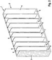
- FIGS. 1 to 3 show a shaft tray 1, which has two side walls 3 and 4, a bottom wall 5 and a rear wall 6 to form an inclined body 2.
- the side walls 3, 4 are arranged substantially parallel spaced (may not be seen from the figures have Entformungsschrägen) and limit a defined by the Schragen Sciences 2 receiving space 7 side.
- the bottom wall 5 limits the receiving space 7 down.
- the shaft trays 1 are formed open to the front and top. Of course, front walls and cover elements can be provided.
- the tray body 2 may be formed in one piece or in several parts.
- the receiving space 7 itself is subdivided.
- the shaft walls 8 can also be formed integrally with the tray body 2.
- the shaft walls 8 run parallel and spaced from each other or to the side walls 3, 4th
- the tray 1 can also be formed without shaft walls 8 as standard trays.
- the Schragen is made of electrically conductive plastic.
- This may be either a so-called intrinsically conductive polymer which has a conductivity per se, as well as a plastic, which is given an electrical conductivity by the addition of additives.
- the in the Figures 2 and 3 shown Schragen is made of a plastic with the addition of additives.
- fibers of an inorganic substance are included. Such fibers may in particular be stainless steel fibers or carbon fibers.
- the conductivity in the fiber direction is much higher than perpendicular to it.
- the fibers are substantially parallel to the longitudinal extent of the Schragen cleanse- and dividing walls 3, 8 is formed.
- the fibers extend substantially parallel to the longitudinal extent of the sloping floor 5.
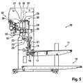
- the in the FIGS. 4 to 6 Emptying device 10 shown comprises a feed device 11, a removal device 12, a discharge station 32 and a transfer device 13.
- the feeder 11 is used for feeding and storing products filled (full) slants 14 of electrically conductive material.
- the feed device 11 is arranged above the removal device 12 and, like the removal device 12, runs substantially horizontally.
- Substantially horizontal also expressly includes a slight inclination with an angle greater than 0 ° and less than 5 ° with respect to a horizontal plane, such that the feeder 11 drops slightly in the direction of the transfer device 13, so that the containers 14 with respect to a vertical orientation about the corresponding angle ⁇ inclined on the feeder 11 stand.
- an inclination of 3 ° is selected from the vertical.
- the full trays 14 can be transported from a pick-up position 17 into the region of an emptying magazine 18 and back into a dispensing position 19.
- the emptying magazine 18 may be part of the emptying station 32 or arranged as a separate part under the emptying position.
- a stopper 15 In the region of the pick-up position 17 is a stopper 15 which holds the tray in the pick-up position 17 until it is received by the transfer device.
- the feeder 11 continues to run below the tray 14, which in conventional devices builds up electrostatic charge in the tray.
- the feed device 11 is designed as a conveyor belt, wherein the conveyor belt consists of a conductive plastic.
- the transfer device 13 comprises a cassette 21, which is designed to be vertically movable up and down and pivotable. The vertical and pivotal movements are direct or indirectly through the cassette 21 executable. Further, the cassette 21 for holding a tray 14, 16 is formed and set up during the entire unloading operation. This means that the cassette has means for holding and / or gripping the casings 14, 16, by means of which the casings 14, 16 are fixed in a defined position, which may also be inclined to the vertical, within the cassette 21. Preferably, pneumatic gripping elements are provided.
- the holding of the casings 14, 16 itself can be realized, for example, by metallic spring elements or the like. Of course, all other conventional holding and / or gripping mechanisms are used, which consist of conductive material.
- the cassette 21 is optionally associated with a pick-up element 22.
- the pick-up element 22 is further adapted and adapted to position the full tray 14 within the cassette 21 so that it is fixable in the "center-product" position.
- the "center-product” position which is also known by the term “constant edge”, is advantageous for handling different product lengths in the course of a format changeover.
- the pick-up element 22 can furthermore also have a push-off element (not shown) by means of which the ejection of the emptied tray 16 from the cassette 21 is assisted.
- the Abschiebelement can also be provided as a separate device.
- the emptying device 10 preferably has a lifting device 23 as part of the transfer device 13.
- the lifting device 23 comprises vertically extending guide rails 24 or the like, on which or in which a lift fork 25 or the like is guided and a drive unit 26.
- the transfer device 13 comprises a pivoting device 27.
- the pivoting device 27 is between the transfer position 20 and the emptying position arranged and executed to perform an over-head pivotal movement of the full tray 14 holding cassette 21 via the discharge magazine 18 and the then emptied tray 16 holding cassette 21 back and formed.
- the pivoting device 27 is arranged at the upper end of the guide rails 24 and forms a pivoting head.
- the pivoting device 27 has a latching device 28 and a rotatable and stationary shaft 29, wherein the latching device 28 is mounted on the shaft 29.
- the shaft 29 itself is fixed to a frame or the like but rotatably mounted.
- the shaft 29 together with the cassette 21 forms the charge-removing element, by means of which the charge present in the carriage can be discharged via the base frame 33 of the emptying device 10.
- a copper braid (not shown) may be provided, which supports the charge dissipation.
- the latching device 28 comprises a plurality of latching bolts (not shown), e.g. by means of (also not shown) pneumatic cylinders or the like can be actuated.
- the cassette 21 is detachable from the lifting device 23 and can be connected to the pivoting device 27 and vice versa.
- the locking of the cassette 21 on the pivoting device 27 and the corresponding unlocking can be done in other usual ways, provided that the conductive connection between the pivoting device 27, cassette 21 and tray 14 is made.
- the distance between the axis of rotation D of the shaft 29 and the means of the latching device 28 on the shaft 29 rotatably or pivotally mounted cassette 21 is made small.
- the locking device 28 is designed to be very short with respect to the design, so that the cassette 21 during the pivoting movement describes a very narrow envelope with a small radius.
- the cassette 21 is arranged in the immediate vicinity of the shaft 29 or directly thereon.
- a drive 30 for carrying out the pivoting movement is associated with the transfer device 13 and arranged in extension of the shaft 29.
- the collection position 17 for the full trays 14 and the discharge position 19 for the empty containers 16 may be at different positions.
- the pickup position 17 corresponds to the dispensing position 19.
- both the pickup position 17 and the dispensing position 19 are at the same level, namely at the level of the feed device 11.
- the lift device 31 for transporting the empty containers 16 from the discharge position 19 on the Abtransport Ran is formed separately to the lifting device 23 for transporting the full tray 14 from the pickup position 17 in the emptying position and back to the dispensing position 19.
- At least one full tray 14, but preferably several full trays 14 are arranged or stored on the feeder 11.
- the trays 14 stand with a narrow side on the slightly sloping in the direction of the transfer device 13 feeder 11, so that the trays 14 are inclined by the angle ⁇ to the vertical in the direction of the transfer device 13 in the pickup position 17.
- the Schragen 14 can of course be transported without inclination.
- a full tray 14 is transported from the pick-up position 17 to the emptying position in the region of the emptying magazine 18.
- the transport preferably takes place in that the full tray 14 is pulled by the pick-up element 22 into the cassette 21 and positioned there.
- either the tray 14 itself or the cassette 21 is pivoted at an angle to the vertical which is greater than the angle ⁇ . With this overall inclination by the angle ⁇ to the vertical, the cassette 21 with the tray 14 is moved by means of the lifting device 23 vertically upwards into the region of the emptying magazine 18.
- the cassette 21 is released from the lifting device 23 and connected to the pivoting device 27.
- latching pins of the latching device 28 are moved from a waiting position into the latching position, so that the cassette 21 is fixedly connected to the shaft 29 of the pivoting device 27.
- the shaft 29 is simultaneously connected to the machine base frame 33, so that a charge dissipation takes place possibly in the tray 14 existing electrostatic charge.
- the pivoting device 27 performs a pivoting movement, so that the tray 14 is above the discharge hopper 18.
- the closing element of the tray 14 is opened so that the products fall down from the container 14 into the discharge tray 18.
- the cassette 21 pivots back with the emptied tray 16.
- the cassette 21 with the emptied tray 16 is released from the pivoting device 27 and reconnected to the lifting device 23.
- the lifting device 23 transports the emptied tray 16 down to the dispensing position 19. During the entire emptying process from the picking position 17 to the area of the emptying magazine 18 and back to the dispensing position 19, the tray 14, 16 in the up and down movable and pivotable cassette 21 held.
- a new full tray 14 is picked up by the feeder 11 and positioned in the cassette 21, while at the same time in the cassette 21 located emptied tray 16 is pushed or pushed out of the cassette 21.
- the ejection or ejection can be done by the full tray 14 and / or by a Abschiebelement.
- the emptied tray 16 is pushed out of the cassette 21 onto the lifting device 31, by means of which the emptied tray 16 is transported from the level of the feed device 11 downwards into the area of the removal device 12 and delivered to it.
Description
Die vorliegende Erfindung betrifft Schragen zur Aufnahme stabförmiger Produkte der Tabak verarbeitenden Industrie, umfassend einen durch eine Rückwand, zwei zumindest im Wesentlichen parallele und beabstandet zueinander angeordnete Seitenwände sowie eine Bodenwand gebildeten Schragenkörper unter Bildung eines nach vorn und nach oben offen ausgebildeten Aufnahmeraumes für die Produkte, wobei der Schragen als Schachtschragen ausgebildet sein kann.The present invention relates to trays for receiving rod-shaped products of the tobacco-processing industry, comprising an inclined body formed by a rear wall, two at least substantially parallel and spaced apart side walls and a bottom wall forming a forward and upwardly open receiving space for the products, wherein the tray may be formed as a shaft tray.
Die Erfindung betrifft ferner eine Schragenentleereinrichtung zum automatischen Entleeren von mit stabförmigen Produkten gefüllten Schragen in eine Produktions- oder Verpackungsmaschine der Tabak verarbeitenden Industrie, umfassend eine Zuführeinrichtung zum Zuführen mit stabförmigen Produkten gefüllter Schragen, eine Entleerstation mit einer Entleerposition zum über Kopf Entleeren der Schragen, eine Abtransporteinrichtung zum Abtransportieren der entleerten Schragen sowie eine Übergabeeinrichtung zum Transportieren der Schragen innerhalb der Schragenentleereinrichtung während eines Entleerzyklus, sowie ein Verfahren zum automatischen Entleeren von mit stabförmigen Produkten gefüllten Schragen, umfassend die Schritte Zuführen von mit Produkten gefüllten Schragen mittels einer Zuführeinrichtung, Transportieren der Schragen von der Zuführeinrichtung in eine Entleerposition einer Entleerstation mittels einer Übergabeeinrichtung, so dass die Schragen über Kopf in der Entleerposition stehen, über Kopf Entleeren der Schragen, Transportieren der Leerschragen mittels der Übergabeeinrichtung von der Entleerposition auf eine Abtransporteinrichtung, und Abtransportieren der Leerschragen mittels der Abtransporteinrichtung.The invention further relates to a tray emptying device for automatically discharging sticks filled with rod-shaped products into a production or packaging machine of the tobacco-processing industry, comprising a feeder for feeding sticks filled with rod-shaped products, an emptying station with an emptying position for emptying the trays overhead A removal device for removing the emptied trays and a transfer device for transporting the trays within the tray emptying device during a discharge cycle, and a method for automatically emptying rod-shaped product filled trays, comprising the steps of feeding product-filled trays by means of a feeder, transporting the trays of the feeder in an emptying position of an emptying station by means of a transfer device, so that the Schragen overhead in the Entle erposition are, overhead emptying of the trays, transporting the empty trays by means of the transfer device from the emptying position on a Abtransporteinrichtung, and transporting the empty trays using the Abtransporteinrichtung.
Die beschriebenen Schragen kommen insbesondere in der Tabak verarbeitenden Industrie bei der Verarbeitung stabförmiger Produkte zum Einsatz. Tabakstöcke, Zigaretten, Filterstäbe und insbesondere Filterstabsegmente oder dergleichen werden in Behältern, den so genannten Schragen, insbesondere zum Transport und zur Speicherung aufbewahrt. Dabei können die Behälter als Standardschragen mit einem einzigen Aufnahmeraum für alle Produkte oder als Schachtschragen ausgebildet sein, in denen die Produkte in mehreren voneinander getrennten Schächten liegen. Zur Weiterverarbeitung der gespeicherten Produkte werden diese an nachgeordnete Vorrichtungen, wie z.B. Packmaschinen oder dergleichen abgegeben oder in einen vorhandenen Massenstrom eingeschleust.The Schrage described are used in particular in the tobacco processing industry in the processing of rod-shaped products used. Tobacco sticks, cigarettes, filter rods and in particular filter rod segments or the like are stored in containers, the so-called Schragen, in particular for transport and storage. The containers may be designed as standard trays with a single receiving space for all products or as shaft trays in which the products are located in several separate shafts. For further processing the stored products are delivered to downstream devices, such as packing machines or the like or introduced into an existing mass flow.
Solche Schragen sind heutzutage üblicherweise aus Kunststoff wie beispielsweise Polystyrol (PS) oder Acrylnitril-Butadien-Styrol (ABS) hergestellt, da dieses Material stabil und gleichzeitig leicht sowie kostengünstig ist. Derartige Schragen sind zum Beispiel im DE-Gbm. 1 882 950 beschrieben.Such skins today are usually made of plastic such as polystyrene (PS) or acrylonitrile-butadiene-styrene (ABS), since this material is stable and at the same time easy and inexpensive. Such Schragen are for example in DE-Gbm. 1 882 950.
Eine nachgeordnete Vorrichtung, in der Schragen zum Einsatz kommen, ist eine Schragenentleereinrichtung, mit Hilfe derer stabförmige Artikel, die aus unterschiedlichen Gründen in Schragen, gelagert werden, wieder in den Produktionsprozess einführt werden. Dazu sind die Schragenentleereinrichtungen mit Produktionsmaschinen zu einer Produktionsanordnung zum Ausführen entsprechender Herstellungsverfahren, zu denen die Zigarettenherstellung, die Filterherstellung und auch das Verpacken derselben gehören, kombiniert.A subordinate device in which trays are used is a tray emptying device by means of which rod-shaped articles, which are stored for different reasons in trays, are reintroduced into the production process. For this purpose, the tray emptying devices are combined with production machines to form a production arrangement for carrying out corresponding production methods, which include the cigarette production, the filter production and also the packaging thereof.
Bekannte Schragenentleereinrichtungen weisen Übergabeeinrichtungen zum Handhaben bzw. zum Handling der Schragen auf, die als Schwenkmechanismus ausgebildet sind. Mit dem bekannten Schwenkmechanismus werden sämtliche Schragen, also die Vollschragen und die Leerschragen, während des Entleerzyklus gehandhabt. Ein Entleerzyklus umfasst das Abnehmen der Vollschragen von der Zuführeinrichtung, das über Kopf Entleeren der Vollschragen in der Entleerstation und das Abgeben der Leerschragen an die Abtransporteinrichtung.Known tray emptying devices have transfer devices for handling or handling the trays, which are designed as a pivoting mechanism. With the known pivot mechanism all Schragen, so the full trays and the Leerschragen, handled during the Entleerzyklus. An emptying cycle comprises removing the full trays from the feeder, emptying the full trays in the emptying station overhead and discharging the empty trays to the removal device.
Solche Schragenentleereinrichtungen sind zum Beispiel in der
Bei den bekannten Schragenentleereinrichtungen tritt das Problem auf, dass bei bzw. nach dem Entleeren stabförmige Produkte in dem Schragen verbleiben, obwohl der Schragen in der Schragenentleereinrichtung vollständig hätte entladen werden sollen. An Boden und/oder Wand des Schragens bleiben stabförmige Produkte hängen, da sich ein elektrostatisches Feld im Schragen gebildet hat, das die stabförmigen Produkte am Herausfallen hindert. Ein solches elektrostatisches Feld bildet sich aufgrund des Umstandes, dass die Schragen aus Kunststoff, einem dielektrischen Material hergestellt sind, durch Reibung. Reibung tritt auf der einen Seite auf, wenn die stabförmigen Produkte in den Schragen gefüllt werden, wobei sie gegen die Wände und den Boden des Schragens reiben. Dabei laden sich Schragenwände bzw. -boden und stabförmige Produkte mit unterschiedlichen Ladungen auf, was zur Bildung eines elektrostatischen Feldes führt, das verhindert, dass sich die Schragen in der Entleereinrichtung vollständig entleeren lassen, wie eigentlich gewünscht. Eine weitere Aufladung erfolgt dadurch, dass die Schragen auf ihrem Transport mit anderen Gegenständen aus Kunststoff in Berührung kommen. So sind zum Beispiel die Transportbänder zum einen der Zuführeinrichtung, zum anderen der Abtransporteinrichtung üblicherweise aus Kunststoff hergestellt. Durch die Reibung zwischen Schragen und Transportband entsteht wiederum elektrische Ladung. Besonders relevant tritt eine solche Ladung bei der Übergabe des Schragens von Zuführeinrichtung zu Entleerstation auf, wenn der Schragen mittels eines Stoppers zwecks Übergabe an die Entleereinrichtung angehalten wird, während das Transportband der Zuführeinrichtung unter dem Schragen weiterläuft. Je trockener die Umgebungsluft ist, umso größer ist dabei die entstehende elektrostatische Aufladung.In the known tray emptying devices, the problem arises that rod-shaped products remain in the tray during emptying, even though the tray in the tray emptying device should have been completely unloaded. At the bottom and / or wall of the tray stick rod-shaped products hang because an electrostatic field has formed in the Schragen, which prevents the rod-shaped products from falling out. Such an electrostatic field is due to the fact that the plastic trays are made of a dielectric material by friction. Friction occurs on one side when the rod-shaped Products are filled in the trays, rubbing against the walls and floor of the tray. It load Schragenwände or floor and rod-shaped products with different charges, resulting in the formation of an electrostatic field, which prevents the Schragen can be completely empty in the emptying, as actually desired. Another charge is made by the fact that the Schragen come into contact with other plastic objects on their transport. Thus, for example, the conveyor belts on the one hand the feeder, on the other hand, the removal device usually made of plastic. The friction between the carriage and the conveyor belt produces electrical charge. Particularly relevant occurs such a charge in the transfer of the tray of feed to emptying station when the Schrage is stopped by means of a stopper for the purpose of transfer to the emptying while the conveyor belt of the feeder continues under the Schragen. The drier the ambient air is, the greater the resulting electrostatic charge.
Bislang wird diesem Problem Rechnung getragen, in dem die Leerschragen von einer Person kontrolliert und ggf. verbliebene stabförmige Produkte manuell entfernt werden. Mit einem zunehmenden Grad an Automatisierung in der Produktion, der insbesondere zur einer Kostensenkung führen soll, fehlt es im gesamten Prozess jedoch zunehmend an Personen, die eine solche Kontrollfunktion ausüben könnten.So far, this problem is taken into account, in which the empty trays controlled by a person and possibly remaining rod-shaped products are removed manually. However, with an increasing degree of automation in production, in particular with the aim of reducing costs, the whole process is increasingly lacking people who could exercise such a control function.
Es ist daher wünschenswert, sicherzustellen, dass nach Möglichkeit keine stabförmigen Produkte nach dem Entleervorgang im Schragen verbleiben.It is therefore desirable to ensure that, if possible, no rod-shaped products remain in the tray after the emptying process.
Hierzu schlägt die
Das Vorsehen einer Einrichtung zum Einblasen ionisierter Druckluft ist konstruktiv aufwendig und mit erhöhten Kosten verbunden. Auch das Vorsehen von Einlagen oder Einsätzen ist aufwendig, da bei der Herstellung der Schragen ein zusätzlicher Arbeitsschritt des Einsetzens der Einlage erforderlich ist, was wiederum die Kosten erhöht. Auch besteht die Gefahr, dass sich Einlage oder Einsatz vom Schragen lösen, in die Maschinen geraten und zu Beschädigungen führen.The provision of a device for blowing ionized compressed air is structurally complex and associated with increased costs. Also, the provision of deposits or inserts is expensive, since in the production of the Schragen an additional step of inserting the insert is required, which in turn costs elevated. There is also the risk that the insert or insert will come off the tray, get into the machine and cause damage.
Aufgabe der vorliegenden Erfindung ist es daher, einen Schragen zur Verfügung zu stellen, dessen vollständige Entleerung sichergestellt werden kann und der gleichzeitig einfach und kostengünstig herzustellen ist.Object of the present invention is therefore to provide a Schragen available, the complete emptying can be ensured and at the same time is simple and inexpensive to manufacture.
Diese Aufgabe wird erfindungsgemäß durch einen Schragen der eingangs genannten Art gelöst, der zumindest teilweise aus elektrisch leitfähigem Kunststoff gebildet ist. Durch die Verwendung von elektrisch leitfähigem Kunststoff als Schragenmaterial kann entstehende Aufladung unmittelbar abgeleitet werden. Es ist kein Aufbringen einer zusätzlichen Schicht, einer Einlage oder dergleichen erforderlich. Der Schragen kann konstruktiv sehr einfach hergestellt werden. Ein elektrisch leitfähiger Kunststoff im Sinne der Erfindung ist dabei ein Kunststoff, der - anders als Kunststoffe üblicherweise, die als hervorragende Isolatoren gelten - eine elektrische Leitfähigkeit von mindestens 10-10 S cm-1 aufweist. Im Sinne der Erfindung werden unter elektrisch leitfähigen Kunststoffen dabei sowohl die sogenannten intrinsisch leitfähigen Polymere verstanden, die per se eine Leitfähigkeit aufweisen, wie auch solche Kunststoffe, denen durch Zusatz von Additiven eine elektrische Leitfähigkeit verliehen wird.This object is achieved by a Schragen of the type mentioned, which is at least partially formed of electrically conductive plastic. By using electrically conductive plastic as Schragen material resulting charge can be derived immediately. No application of an additional layer, liner or the like is required. The Schragen can be made structurally very easy. An electrically conductive plastic according to the invention is a plastic which - unlike plastics usually, which are considered excellent insulators - has an electrical conductivity of at least 10 -10 S cm -1 . For the purposes of the invention, electrically conductive plastics are understood as meaning both the so-called intrinsically conductive polymers which have a conductivity per se, as well as those plastics which are given electrical conductivity by the addition of additives.
Dies gelingt besonders gut, wenn der gesamte Schragen aus elektrisch leitfähigem Kunststoff gebildet ist. Vorteilhafterweise ist der Schragen dabei einstückig ausgebildet und im Spritzgussverfahren hergestellt. Auf diese Weise wird ein sehr stabiler Schragen erhalten, der gleichzeitig kostengünstig in der Herstellung ist. Auch können bereits vorhandene Formen zur Schragenherstellung weiter verwendet werden, da sich lediglich das Material ändert, während die Schragenform identisch bleibt.This is particularly well when the entire Schragen is formed of electrically conductive plastic. Advantageously, the Schragen is integrally formed and manufactured by injection molding. In this way, a very stable Schragen is obtained, which is also inexpensive to manufacture. Also existing forms for Schragenherstellung can be used because only the material changes while the Schragenform remains identical.
Der erfindungsgemäße Schragen kann auch ein Schachtschragen sein, d.h. ein Schragen, in dem die Produkte in mehreren voneinander durch Zwischenwände getrennten Schächten liegen. Vorteilhafterweise bestehen dabei auch die Zwischenwände aus elektrisch leitfähigem Kunststoff.The tray according to the invention may also be a tray tray, i. a Schragen, in which the products lie in several mutually separated by partitions shafts. Advantageously, the intermediate walls also consist of electrically conductive plastic.
Eine besonders geeignete Gruppe elektrisch leitfähiger Kunststoffe sind Polymere, die ein elektrisch leitendes Additiv enthalten. Hierbei können anorganische Additive wie auch organische Additive zum Einsatz kommen. Bevorzugte anorganische Additive sind Kohlenstofffasern, Leitfähigkeitsruß, Graphit, Edelstahl, Kupfer, Aluminium, Silber und Eisenoxid. Die Metalle können in Form von Fasern, Pulver, Flocken oder Teilchen zugesetzt werden. Dabei kommt bzw. kommen Edelstahl vorteilhafterweise in Form von Fasern, Kupfer, Aluminium und Eisenoxid in Form von Teilchen und Silber in Form von Pulver zur Anwendung.A particularly suitable group of electrically conductive plastics are polymers containing an electrically conductive additive. In this case, inorganic additives as well as organic additives can be used. Preferred inorganic additives are carbon fibers, conductivity black, graphite, stainless steel, copper, aluminum, silver and iron oxide. The metals may be added in the form of fibers, powders, flakes or particles. In this case, stainless steel is advantageously used in the form of fibers, copper, aluminum and iron oxide in the form of particles and silver in the form of powder.
Besonders bevorzugt ist die Verwendung von Kohlenstofffasern. Solche sogenannten kohlenstofffaserverstärkten Kunststoffe (CFK = Carbon-faserverstärkter Kunststoff) weisen neben der gewünschten elektrischen Leitfähigkeit Festigkeit und Steifigkeit auf. Da elektrische Leitfähigkeit, Festigkeit und Steifigkeit durch die Kohlenstofffasern verliehen werden, sind diese Eigenschaften abhängig von der Faserrichtung. Sie sind in Faserrichtung deutlich höher als senkrecht dazu. Diese Eigenschaft kann man sich bei der Herstellung der Schragen zunutze machen. So ist es möglich, beispielsweise durch Herstellung im Spritzgussverfahren, die Faseranordnung so zu wählen, dass eine besonders günstige Ableitung der Ladung erfolgen kann, zum Beispiel in Richtung zu den Schragenseitenwänden hin oder senkrecht zu entlang der Schragenseitenwand. Die Ausrichtung kann zum Beispiel in Abhängigkeit der Ableitelemente gewählt werden, die die elektrische Ladung vom Schragen an der Maschine ableiten. Auf der anderen Seite lässt sich, wenn gewünscht, auch eine chaotische Anordnung der Fasern erreichen, zum Beispiel durch Herstellung der Schragen im Pressverfahren.Particularly preferred is the use of carbon fibers. Such so-called carbon fiber reinforced plastics (CRP = carbon fiber reinforced plastic) have in addition to the desired electrical conductivity strength and rigidity. Since electrical conductivity, strength and rigidity are imparted by the carbon fibers, these properties are dependent on the fiber direction. They are much higher in the fiber direction than perpendicular to it. This property can be used in the manufacture of the Schragen. Thus, it is possible, for example by production by injection molding, to choose the fiber arrangement so that a particularly favorable dissipation of the charge can take place, for example in the direction of the Schragen side walls or perpendicular to along the Schragenseitenwand. The orientation may be chosen, for example, depending on the diverters that divert the electrical charge from the tray on the machine. On the other hand, if desired, a chaotic arrangement of the fibers can also be achieved, for example by producing the casings in the pressing process.
In einer anderen bevorzugten Ausführungsform ist das elektrisch leitende Additiv ein organisches elektrostatisch dissipatives Additiv, insbesondere ausgewählt aus mindestens einer Substanz der Gruppe bestehend aus Polyanilinen, Polyurethanen, Polyethylendioxythiophenen und Polyacrylaten. Solche organischen Additive sind besonders geeignet, da sich durch geeignete Wahl der jeweiligen Verbindung Leitfähigkeiten in einem breiten Spektrum realisieren lassen. Auch sind solche Additive mit anderen Additiven mischbar, um weitere Eigenschaften der Schragen einzustellen.In another preferred embodiment, the electrically conductive additive is an organic, electrostatic dissipative additive, in particular selected from at least one substance from the group consisting of polyanilines, polyurethanes, Polyethylendioxythiophenen and polyacrylates. Such organic additives are particularly suitable because can be realized by a suitable choice of the respective compound conductivities in a wide range. Also, such additives are miscible with other additives to adjust other properties of the Schragen.
In noch einer anderen bevorzugten Ausführungsform ist der elektrisch leitfähige Kunststoff ein intrinsisch leitfähiges Polymer, insbesondere ein dotiertes intrinsisch leitfähiges Polymer. Unter den intrinsisch leitfähigen Polymeren sind insbesondere das cis-Polyactetylen (cis-PA), das trans-Polyacetylen (trans-PA), Poly(paraphenylen) (PPP), Polythiophen, Polypyrrol, Poly(para-phenylen-vinylen) (PPV) und Polyanilin (PANI) zu nennen. Besonders bevorzugt, weil eine um mehrere Zehnerpotenzen höhere Leitfähigkeit aufweisend, sind solche Polymere, die dotiert sind, d.h. in die eine geringe Menge Fremdatome eingebaut sind.In yet another preferred embodiment, the electrically conductive plastic is an intrinsically conductive polymer, in particular a doped intrinsically conductive polymer. Among the intrinsically conductive polymers are in particular the cis-polyactetylene (cis-PA), the trans-polyacetylene (trans-PA), poly (paraphenylene) (PPP), polythiophene, polypyrrole, poly (para-phenylene-vinylene) (PPV) and polyaniline (PANI). Particularly preferred, because having a conductivity of several orders of magnitude higher, are those polymers which are doped, ie in which a small amount of foreign atoms are incorporated.
Der erfindungsgemäße leitfähige Kunststoffschragen weist eine stark reduzierte Haftung der Artikel an dessen Innenwänden auf. Dies wirkt sich vorteilhaft auf die Füll- und die Entleervorgänge aus, jedoch könnte sich dies möglicherweise nachteilig hinsichtlich eines sicheren Transports der mit stabförmigen Artikeln gefüllten aufrecht stehenden Schragen, insbesondere bei Beschleunigungs- und/oder Verzögerungsvorgängen auswirken.The conductive plastic tray according to the invention has a greatly reduced adhesion of the articles to its inner walls. This has an advantageous effect on the filling and emptying operations, but this could potentially be detrimental to the safe transport of upright strands filled with rod-shaped articles, particularly during acceleration and / or deceleration operations.
In einer Weiterbildung des erfindungsgemäßen Schragen ist deshalb vorgesehen, dass die Rückwand des Schragens auf ihrer Inneseite um wenigstens 1 Grad aus der Senkrechten gegenüber der senkrechten Außenseite geneigt ist, wobei die Wandstärke der Rückwand von oben nach unten zur Bodenwand zunimmt.In a further development of the invention Schragen is therefore provided that the rear wall of the tray is inclined on its inner side by at least 1 degree from the vertical relative to the vertical outside, the wall thickness of the rear wall increases from top to bottom to the bottom wall.
Aufgrund der sich zur offenen Oberseite hin verjüngenden Rückwand ergeben sich zudem Vorteile bei der Herstellung des Kunststoffschragens, es ist hiermit nämlich eine sogenannte Entformungsschräge geschaffen.Due to the tapering towards the open top rear wall also benefits in the production of the plastic tray, there is hereby created a so-called Entformungsschräge.
In einer Weiterbildung des erfindungsgemäßen Schragens ist weiterhin vorgesehen, dass die Bodenwand des Schragens auf ihrer Innenseite um wenigstens 1 Grad aus der Waagerechten gegenüber der waagerechten Außenseite geneigt ist, wobei die Wandstärke der Bodenwand von vorn nach hinten zur Rückwand abnimmt.In a further development of the invention Schrägens is further provided that the bottom wall of the tray is inclined on its inside by at least 1 degree from the horizontal relative to the horizontal outside, the wall thickness of the bottom wall decreases from front to back to the rear wall.
Vorzugsweise sind die Innenseiten der Rückwand und der Bodenwand um etwa denselben Winkelbetrag geneigt, so dass der eingeschlossene Winkel etwa 90 Grad beträgt.Preferably, the inner sides of the rear wall and the bottom wall are inclined by approximately the same angular amount, so that the included angle is about 90 degrees.
Durch die vorbeschriebenen Weiterbildungen ist nunmehr ein sicherer Transport der Artikel in aufrecht stehenden Schragen möglich, ohne dass die Fördermittel, insbesondere für den Transport von Vollschragen wie üblich in Schragenfülleinrichtungen und Schragenentleereinrichtungen geneigt ausgeführt sind. Um ein sicheres Füllen oder Entleeren der Schragen in den Schragenfülleinrichtungen bzw. in den Schragenentleereinrichtungen zu gewährleisten werden die Schragen zum Füllen bzw. zum Entleeren mittels einer Schwenkvorrichtung derart geneigt, dass die Innenseite der Rückwand des Schragens in derselben, vorzugsweise vertikalen Ebene liegt, wie die vorgeordnete oder nachgeordnete Rückwand des Zwischen- oder Pufferspeichers der Schragenfülleinrichtung bzw. der Schragenentleereinrichtung.The above-described developments now secure transport of the article in upright Schragen is possible without the funding, especially for the transport of solid trays are carried out as usual in Schragenfülleinrichtungen and Schragenentleereinrichtungen inclined. In order to ensure a safe filling or emptying of the trays in the Schragenfülleinrichtungen or in Schragenentleereinrichtungen the trays for filling or emptying by means of a pivoting device are inclined so that the inside of the rear wall of the tray is in the same, preferably vertical plane as the upstream or downstream rear wall of the intermediate or buffer memory of the Schragenfülleinrichtung or the Schragenentleereinrichtung.
Die Aufgabe wird auch durch eine Schragenentleereinrichtung der eingangs genannten Art gelöst, bei der an zumindest einer Einrichtung, ausgewählt aus Zuführeinrichtung, Entleerstation, Abtransporteinrichtung und Übergabeeinrichtung, zumindest ein ladungsabführendes Element vorgesehen ist, das ausgebildet und eingerichtet ist, um einen Kontakt zwischen dem Schragen und dem geerdeten Maschinengrundgestell herzustellen.The object is also achieved by a tray emptying device of the type mentioned, in which at least one device, selected from feeder, emptying, Abtransporteinrichtung and transfer device, at least one charge dissipating element is provided, which is designed and adapted to make contact between the Schragen and to produce the grounded machine base frame.
Wie vorstehend ausgeführt ist es sehr vorteilhaft, wenn die Schragen aus elektrisch leitfähigem Kunststoff bestehen, da somit eine Ableitung der durch Reibung entstehenden Ladung möglich ist. Um den gewünschten Effekt zu erzielen ist es erforderlich, dass die Ladung aus dem Schragen abgeleitet wird. Übliche Maschinen und Einrichtungen in der tabakverarbeitenden Industrie weisen ein Maschinengrundgestell auf, an dem die einzelnen Komponenten und Teile angebracht sind. Dieses Maschinengrundgestell ist stets geerdet. Es ist daher bestens geeignet, die entstandene Ladung abzuleiten. Dazu ist es erforderlich, eine leitende Verbindung zwischen den mit Ladung behafteten Schragen und dem Maschinengrundgestell herzustellen. Erfindungsgemäß wird diese durch mindestens ein ladungsabführendes Element vorgesehen, das entweder an der Zuführeinrichtung, an der Entleerstation, an der Abtransporteinrichtung oder an der Übergabeeinrichtung angebracht ist. Das ladungsabführende Element bzw. die ladungsabführenden Elemente können insbesondere als Kontaktflächen aus Metall ausgebildet sein. Dabei als Metalle Silber, Kupfer und Eisen, die gute elektrische Leiter sind, besonders geeignet.As stated above, it is very advantageous if the trays are made of electrically conductive plastic, since thus a derivative of the resulting charge by friction is possible. In order to achieve the desired effect, it is necessary that the charge is discharged from the tray. Conventional machines and equipment in the tobacco processing industry have a machine base on which the individual components and parts are mounted. This machine base is always earthed. It is therefore ideally suited to dissipate the resulting charge. For this purpose, it is necessary to establish a conductive connection between the load-bearing Schragen and the machine base frame. According to the invention, this is provided by at least one charge-discharging element, which is attached either to the feed device, to the emptying station, to the removal device or to the transfer device. The charge-removing element or the charge-dissipating elements may in particular be designed as contact surfaces made of metal. It is particularly suitable as metals silver, copper and iron, which are good electrical conductors.
In einer bevorzugten Ausführungsform der Schragenentleereinrichtung weist deren Übergabeeinrichtung einen eine auf 180° begrenzte Schwenkbewegung ausführenden Schwenkmechanismus mit einer um eine ortsfeste Schwenkachse S schwenkbaren Schwenkkassette, die zum Fixieren, Schwenken und Freigeben der Schragen ausgebildet und eingerichtet ist, auf, wobei die Schwenkachse das ladungsabführende Element ist. Eine besonders gute Ableitung ist gewährleistet, wenn der Schwenkmechanismus zusätzlich mit einem Kupfergeflecht versehen ist. Da die Schwenkbewegung der Kassette auf 180° beschränkt ist, sind Probleme durch ein etwaiges Verdrehen des Geflechtes ausgeschlossen.In a preferred embodiment of the tray emptying device, the transfer device thereof has a swivel mechanism which executes a swivel movement limited to 180 ° with a swiveling cassette pivotable about a stationary swiveling axis S, which is designed and arranged for fixing, pivoting and releasing the chutes, wherein the swiveling axis is the charge-removing element is. A particularly good dissipation is ensured if the swivel mechanism is additionally provided with a copper braid. Since the pivoting movement of the cassette is limited to 180 °, problems are excluded by a possible twisting of the braid.
Besonders vorteilhaft ist es, wenn im gesamten Prozess möglichst wenig elektrostatische Aufladung generiert wird. Gemäß einer vorteilhaften Ausführungsform ist es daher vorgesehen, dass Zuführeinrichtung und/oder Abtransporteinrichtung als Förderband ausgebildet ist bzw. sind, wobei das Förderband aus einem elektrisch leitfähigen Kunststoff besteht. Auf diese Weise wird bereits die Aufladung, die durch die Reibung zwischen Schragen und Förderband entsteht, weitestgehend vermieden.It is particularly advantageous if as little electrostatic charge as possible is generated in the entire process. According to an advantageous embodiment, it is therefore provided that feed and / or Abtransporteinrichtung is designed as a conveyor belt or are, wherein the conveyor belt consists of an electrically conductive plastic. In this way, even the charge that results from the friction between the tray and conveyor belt, as far as possible avoided.
Schließlich wird die Aufgabe auch durch ein Verfahren der eingangs genannten Art gelöst, bei dem als Schragen die Schragen der vorliegenden Erfindung zum Einsatz kommen und bei dem in mindestens einem der Verfahrensschritte eine Ladungsabführung erfolgt. Mit einem solchen Verfahren wird die statische Aufladung in den Schragen so weit reduziert, dass ein Hängenbleiben von stabförmigen Produkten in den Schragen nach dem Entleervorgang im Wesentlichen ausgeschlossen sein sollte. Das Verfahren ist besonders effektiv und gleichzeitig einfach, da keine aufwendigen zusätzlichen Vorrichtungen zum Beispiel zur Deionisierung vorgesehen werden müssen.Finally, the object is also achieved by a method of the type mentioned, in which as the Schragen the struts of the present invention are used and in which takes place in at least one of the method steps, a charge removal. With such a method, the static charge in the tray is reduced so much that a sticking of rod-shaped products in the tray after the emptying process should be substantially excluded. The method is particularly effective and at the same time simple, since no expensive additional devices have to be provided, for example for deionization.
Weitere zweckmäßige und/oder vorteilhafte Merkmale und Ausgestaltungen ergeben sich aus den Unteransprüchen und der Beschreibung. Eine besonders bevorzugte Ausführungsform sowie das Verfahrensprinzip werden anhand der beigefügten Zeichnung näher erläutert. In der Zeichnung zeigt:
- Fig. 1
- eine perspektivische Darstellung eines erfindungsgemäßen als Schachtschragen ausgebildeten Schragens,
- Fig. 2
- eine Ausführungsform des in
Fig. 1 gezeigten Schragens mit Veranschaulichung der Ausrichtung der Kohlenstofffasern parallel zur Längsrichtung der Schragenwand, - Fig. 3
- eine weitere Ausführungsform des in
Fig. 1 gezeigten Schragens mit Veranschaulichung der Ausrichtung der Kohlenstofffasern parallel zur Längsrichtung des Schragenbodens, - Fig. 4
- eine Seitenansicht der erfindungsgemäßen Entleereinrichtung mit einem auf der Zuführeinrichtung befindlichen Schragen in der Abholposition,
- Fig. 5
- die
Entleereinrichtung gemäß Figur 4 mit dem in eine Kassette aufgenommenen Schragen während der vertikalen Aufwärtsbewegung und - Fig. 6
- die
Entleereinrichtung gemäß Figur 4 mit einer in die Entleerposition geschwenkten Kassette.
- Fig. 1
- a perspective view of a tray according to the invention designed as a shaft tray,
- Fig. 2
- an embodiment of the in
Fig. 1 with an illustration of the orientation of the carbon fibers parallel to the longitudinal direction of the slash wall, - Fig. 3
- another embodiment of the in
Fig. 1 with an illustration of the orientation of the carbon fibers parallel to the longitudinal direction of the slate floor, - Fig. 4
- a side view of the emptying device according to the invention with an on the feeder Schrägen in the pick-up position,
- Fig. 5
- the emptying device according to
FIG. 4 with the recorded in a cassette Schragen during the vertical upward movement and - Fig. 6
- the emptying device according to
FIG. 4 with a cassette pivoted into the emptying position.
Der in den
Die
Der Schragen 1 kann auch ohne Schachtwände 8 als Standardschragen ausgebildet sein.The tray 1 can also be formed without
Der Schragen ist aus elektrisch leitfähigem Kunststoff hergestellt. Dabei kann es sich sowohl um ein sogenanntes intrinsisch leitfähiges Polymere handeln, das per se eine Leitfähigkeit aufweist, wie auch um einen Kunststoff, dem durch Zusatz von Additiven eine elektrische Leitfähigkeit verliehen wird.The Schragen is made of electrically conductive plastic. This may be either a so-called intrinsically conductive polymer which has a conductivity per se, as well as a plastic, which is given an electrical conductivity by the addition of additives.
Der in den
Die in den
Die Übergabeeinrichtung 13 umfasst eine Kassette 21, die vertikal auf und ab bewegbar und schwenkbar ausgebildet ist. Die Vertikal- und Schwenkbewegungen sind direkt oder indirekt durch die Kassette 21 ausführbar. Des Weiteren ist die Kassette 21 zum Halten eines Schragens 14, 16 während des gesamten Entleervorgangs ausgebildet und eingerichtet. Das bedeutet, dass die Kassette Einrichtungen zum Halten und/oder Greifen der Schragen 14, 16 aufweist, mittels der die Schragen 14, 16 in einer definierten Position, die auch geneigt zur Vertikalen sein kann, innerhalb der Kassette 21 fixiert sind. Bevorzugt sind pneumatische Greifelemente vorgesehen. Das Halten der Schragen 14, 16 selbst kann z.B. durch metallische Federelemente oder dergleichen realisiert sein. Selbstverständlich sind auch alle anderen üblichen Halte- und/oder Greifmechanismen einsetzbar, welche aus leitfähigem Material bestehen. Zum Aufnehmen bzw. Abholen der vollen Schragen 14 von der Zuführeinrichtung 11 ist der Kassette 21 optional ein Abholelement 22 zugeordnet. Das Abholelement 22 ist des Weiteren dafür eingerichtet und ausgebildet, den vollen Schragen 14 innerhalb der Kassette 21 zu positionieren, so dass dieser in der "Mitte-Produkt"-Position fixierbar ist. Die auch unter dem Begriff "Konstante Kante" bekannte "Mitte-Produkt"-Position ist für eine Handhabung verschiedener Produktlängen im Zuge einer Formatumstellung vorteilhaft. Das Abholelement 22 kann weiterhin auch ein (nicht dargestelltes) Abschiebelement aufweisen, mittels der das Ausstoßen des entleerten Schragens 16 aus der Kassette 21 unterstützt wird. Das Abschiebelement kann auch als separate Einrichtung vorgesehen sein.The
Zur Ausübung der vertikalen Bewegungen von der Abholposition 17 in die Übergabeposition 20 im Bereich der Schwenkeinrichtung 27 und zurück in die Abgabeposition 19 weist die Entleereinrichtung 10 bevorzugt eine Lifteinrichtung 23 als Bestandteil der Übergabeeinrichtung 13 auf. Die Lifteinrichtung 23 umfasst vertikal verlaufende Führungsschienen 24 oder dergleichen, auf denen bzw. in denen eine Liftgabel 25 oder dergleichen geführt ist sowie eine Antriebseinheit 26. Des Weiteren umfasst die Übergabeeinrichtung 13 eine Schwenkeinrichtung 27. Die Schwenkeinrichtung 27 ist zwischen der Übergabeposition 20 und der Entleerposition angeordnet und zur Ausführung einer über-Kopf-Schwenkbewegung der den vollen Schragen 14 haltenden Kassette 21 über das Entleermagazin 18 sowie der den dann entleerten Schragen 16 haltenden Kassette 21 zurück eingerichtet und ausgebildet. Die Schwenkeinrichtung 27 ist am oberen Ende der Führungsschienen 24 angeordnet und bildet einen Schwenkkopf. Die Schwenkeinrichtung 27 weist eine Rastvorrichtung 28 und eine drehbare und ortsfeste Welle 29 auf, wobei die Rastvorrichtung 28 an der Welle 29 gelagert ist. Die Welle 29 selbst ist an einem Rahmen oder dergleichen ortsfest aber drehbar gelagert. Die Welle 29 bildet zusammen mit der Kassette 21 das ladungsabführende Element, mit Hilfe dessen die im Schragen vorhandene Ladung über das Grundgestell 33 der Entleereinrichtung 10 abgeleitet werden kann. Zusätzlich kann im Bereich der Welle 29 noch ein Kupfergeflecht (nicht gezeigt) vorgesehen sein, das die Ladungsableitung unterstützt.To exercise the vertical movements of the pick-up
Die Rastvorrichtung 28 umfasst mehrere (nicht dargestellte) Rastbolzen auf, die z.B. mittels (ebenfalls nicht dargestellten) Pneumatikzylindern oder dergleichen betätigbar sind. Das bedeutet, dass die beweglich gelagerten Rastbolzen aus einer zurückgezogenen Warteposition, in der die Kassette 21 bei der Übergabe von der Lifteinrichtung 23 an die Schwenkeinrichtung 27 und zurück ein- oder auskoppelbar ist, in eine Rastposition, in der die Kassette 21 fest mit der Schwenkeinrichtung 27 verbunden ist, und zurück bewegbar sind. Mit anderen Worten ist die Kassette 21 von der Lifteinrichtung 23 lösbar und mit der Schwenkeinrichtung 27 verbindbar und umgekehrt. Selbstverständlich kann die Verriegelung der Kassette 21 an der Schwenkeinrichtung 27 und die entsprechende Entriegelung auch auf andere übliche Weise erfolgen, sofern die leitfähige Verbindung zwischen Schwenkeinrichtung 27, Kassette 21 und Schragen 14 hergestellt ist. Der Abstand zwischen der Drehachse D der Welle 29 und der mittels der Rastvorrichtung 28 an der Welle 29 drehbar bzw. schwenkbar gelagerten Kassette 21 ist gering ausgebildet. Das bedeutet, dass die Rastvorrichtung 28 in Bezug auf die Bauform sehr kurz ausgebildet ist, so dass die Kassette 21 bei der Schwenkbewegung eine sehr enge Hüllkurve mit einem kleinen Radius beschreibt. Idealerweise ist die Kassette 21 in unmittelbarer Nähe zur Welle 29 bzw. direkt an dieser angeordnet. Ein Antrieb 30 zur Ausführung der Schwenkbewegung ist der Übergabeeinrichtung 13 zugeordnet und in Verlängerung der Welle 29 angeordnet.The latching
Die Abholposition 17 für die vollen Schragen 14 und die Abgabeposition 19 für die entleerten Behälter 16 können an unterschiedlichen Positionen liegen. Vorzugsweise entspricht die Abholposition 17 aber der Abgabeposition 19. Dadurch kann das Abholen eines vollen Schragens 14 von der Zuführeinrichtung 11 in die Kassette 21 und das Abgeben eines entleerten Behälters 16 aus der Kassette 21 gleichzeitig stattfinden. Dabei liegen in der bevorzugten Ausführungsform sowohl die Abholposition 17 als auch die Abgabeposition 19 auf demselben Niveau, nämlich auf der Höhe der Zuführeinrichtung 11. Um die aus der Kassette 21 abgeschobenen bzw. ausgestoßenen entleerten Schragen 16 in den Bereich der Abtransporteinrichtung 12 zu transportieren, ist im Bereich der unteren Abtransporteinrichtung 12 eine Lifteinrichtung 31 angeordnet. Die Lifteinrichtung 31 zum Transport der entleerten Behälter 16 von der Abgabeposition 19 auf die Abtransporteinrichtung ist separat zur Lifteinrichtung 23 zum Transport der vollen Schragen 14 von der Abholposition 17 in die Entleerposition und zurück in die Abgabeposition 19 ausgebildet. Es ist jedoch auch möglich, für den gesamten Transport der Schragen 14, 16 eine einzige Lifteinrichtung vorzusehen.The
Im Folgenden wird das Verfahrensprinzip anhand der
Mindestens ein voller Schragen 14, vorzugsweise jedoch mehrere volle Schragen 14 sind auf der Zuführeinrichtung 11 angeordnet bzw. bevorratet. Die Schragen 14 stehen mit einer Schmalseite auf der leicht in Richtung der Übergabeeinrichtung 13 abfallenden Zuführeinrichtung 11, so dass die Schragen 14 um den Winkel α zur Vertikalen geneigt in Richtung der Übergabeeinrichtung 13 in die Abholposition 17 transportiert werden. Die Schragen 14 können selbstverständlich auch ohne Neigung transportiert werden. Jeweils ein voller Schragen 14 wird aus der Abholposition 17 in die Entleerposition im Bereich des Entleermagazins 18 transportiert. Der Transport erfolgt vorzugsweise dadurch, dass der volle Schragen 14 durch das Abholelement 22 in die Kassette 21 gezogen und dort positioniert wird. Nachdem der Schragen 14 in der Kassette 21 fixiert worden ist, wird entweder der Schragen 14 selbst oder die Kassette 21 um einen Winkel zur Vertikalen geschwenkt, der größer ist als der Winkel α. Mit dieser Gesamtneigung um den Winkel β zur Vertikalen wird die Kassette 21 mit dem Schragen 14 mittels der Lifteinrichtung 23 vertikal nach oben in den Bereich des Entleermagazins 18 bewegt.At least one
Im Bereich der Übergabeposition 20 wird die Kassette 21 von der Lifteinrichtung 23 gelöst und mit der Schwenkeinrichtung 27 verbunden. Dazu werden Rastbolzen der Rastvorrichtung 28 aus einer Warteposition in die Rastposition bewegt, so dass die Kassette 21 fest mit der Welle 29 der Schwenkeinrichtung 27 verbunden ist. Die Welle 29 ist gleichzeitig mit dem Maschinengrundgestell 33 verbunden, so dass eine Ladungsableitung eventuell in dem Schragen 14 vorhandener elektrostatischer Aufladung erfolgt. Durch eine Drehung der Welle 29 führt die Schwenkeinrichtung 27 eine Schwenkbewegung aus, so dass der Schragen 14 über-Kopf über dem Entleermagazin 18 steht. Das Schließelement des Schragens 14 wird geöffnet, so dass die Produkte nach unten aus dem Behälter 14 in das Entleermagazin 18 fallen. Da die elektrostatische Ladung kurz zuvor über die Welle 29 und das Maschinengrundgestell 33 abgeleitet wird, besteht keine Anziehung mehr zwischen Produkten und Schragen 14, so dass der Schragen 14 vollständig entleert wird und keine Produkte am Boden 5 oder an den Wänden 3, 4, 6 des Schragen zurückbleiben. Nach dem vollständigen Entleeren des Schragens 14 schwenkt die Kassette 21 mit dem entleerten Schragen 16 zurück. Die Kassette 21 mit dem entleerten Schragen 16 wird von der Schwenkeinrichtung 27 gelöst und wieder mit der Lifteinrichtung 23 verbunden. Die Lifteinrichtung 23 transportiert den entleerten Schragen 16 nach unten in die Abgabeposition 19. Während des gesamten Entleervorgangs von der Abholposition 17 in den Bereich des Entleermagazins 18 und zurück in die Abgabeposition 19 wird der Schragen 14, 16 in der auf und ab bewegbaren und schwenkbaren Kassette 21 gehalten.In the region of the
Sobald sich die Kassette 21 nach dem Entleeren eines Schragens 14, 16 wieder in der Abgabeposition 19 befindet, die der Abholposition 17 entspricht, wird ein neuer voller Schragen 14 von der Zuführeinrichtung 11 abgeholt und in der Kassette 21 positioniert, während gleichzeitig der in der Kassette 21 befindliche entleerte Schragen 16 aus der Kassette 21 geschoben oder gestoßen wird. Das Ausschieben bzw. Ausstoßen kann durch den vollen Schragen 14 und/oder durch ein Abschiebelement erfolgen. Der entleerte Schragen 16 wird aus der Kassette 21 auf die Lifteinrichtung 31 geschoben, mittels der der entleerte Schragen 16 vom Niveau der Zuführeinrichtung 11 nach unten in den Bereich der Abtransporteinrichtung 12 transportiert und an diese abgegeben wird.Once the
Wie bereits erwähnt, sind nicht alle für das bevorzugte Ausführen des Verfahrens genannten Schritte notwendig. Entscheidend für ein einfaches und zuverlässiges Verfahren ist es, dass der Schragen 14, 16 während des gesamten Entleervorgangs, also während des Transports und des Entleerens, permanent in der Kassette 21 gehalten wird. Außerdem ist es für ein vollständiges Entleeren erforderlich, dass eine Ableitung der im Prozess am Schragen 14, 16 entstandenen elektrostatischen Ladung erfolgt.As already mentioned, not all steps mentioned for the preferred execution of the method are necessary. It is crucial for a simple and reliable method that the
Claims (12)
- Tray (1) for receiving rod-shaped articles of the tobacco-processing industry, comprising a tray body (2) formed by a rear wall (6), two side walls (3, 4) arranged at least substantially parallel and spaced-apart from each other and a bottom wall (5) providing a receiving space (7) for the products which is designed to be open to the front and above, wherein the tray (1) may be designed as a shaft tray, characterised in that the tray (1) is at least partially constructed of electrically conductive plastic material.
- Tray (1) according to claim 1, characterised in that the entire tray (1) is constructed of electrically conductive plastic material.
- Tray (1) according to claim 1 or 2, characterised in that it is constructed in one piece and is manufactured by injection moulding.
- Tray (1) according to any one of claims 1 to 3, characterised in that the electrically conductive plastic material is a polymer containing an electrically conductive additive.
- Tray (1) according to claim 4, characterised in that the electrically conductive additive is an inorganic additive, selected in particular from at least one substance of the group comprising carbon fibres, stainless steel fibres, conductive carbon black, copper, aluminium and graphite, wherein carbon fibres are particularly preferred.
- Tray (1) according to claim 4, characterised in that the electrically conductive additive is an organic electrostatically dissipative additive, selected in particular from at least one substance of the group comprising polyanilines, polyurethanes, polyethylene dioxythiophenes and polyacrylates.
- Tray (1) according to any one of claims 1 to 3, characterised in that the electrically conductive plastic material is an intrinsically conductive polymer, in particular a doped intrinsically conductive polymer.
- Tray (1) according to any one of claims 1 to 7, characterised in that the rear wall (6) of the tray (1) is inclined on its inside by at least 1 degree from the perpendicular with respect to the vertical outer side, wherein the wall thickness of the rear wall (6) increases from top to bottom towards the bottom wall (5) and/or that the bottom wall (5) of the tray (1) is inclined on its inside by at least 1 degree from the horizontal with respect to the horizontal outer side, wherein the wall thickness of the bottom wall (5) decreases from front to rear towards the back wall (6).
- Tray discharging device (10) for automatically discharging trays (1, 14) filled with rod-shaped articles, in particular according to any one of claims 1 to 7, into a production or packaging machine of the tobacco-processing industry, comprising
a feed device (11) for feeding in trays (14) filled with rod-shaped articles,
a discharge station (32) with a discharge position for overhead emptying of the trays (14),
a removal device (12) for transporting away the emptied trays (16) and
a transfer unit (13) for transporting the trays (14, 16) within the tray discharging device (10) during a discharge cycle,
characterised in that on at least one device, selected from feed device (11), discharge station (32), removal device (12) and transfer unit (13), at least one charge discharging element is provided, which is configured and adapted to establish a contact between the tray (1) and the earthed machine base frame (33). - Tray discharging device (10) according to claim 9, characterised in that the transfer device (13) has a pivoting mechanism executing a pivoting movement limited to 180° with a pivot cassette (21) pivotable about a fixed pivot axis S which is configured and adapted for fixing, pivoting and releasing the trays (14, 16), wherein the pivot axis S is the charge discharging element.
- Tray discharging device (10), according to claim 9 or 10, characterised in that at least one of a feed device (11) and removal device (12) is configured as a conveyor belt, wherein the conveyor belt consists of an electrically conductive plastic material.
- Method for automatically discharging trays (14) filled with rod-shaped articles, comprising the steps- feeding in trays (14) filled with rod-shaped articles by means of a feed device (11),- transporting the trays (14) from the feed device (11) into a discharge position of a discharge station (32) by means of a transfer unit (13), so that the trays are overhead in the discharge position, overhead emptying of the trays,- transporting the empty trays (16) by means of the transfer unit (13) from the discharge station (32) onto a removal device (12), and- transporting away the empty trays (16) by means of the removal device (12),characterised in that the trays (14, 16) are trays according to any one of claims 1 to 7 and that charge discharging takes place in at least one of the method steps.
Priority Applications (1)
| Application Number | Priority Date | Filing Date | Title |
|---|---|---|---|
| PL14164574T PL2805633T5 (en) | 2013-04-15 | 2014-04-14 | Trays made of conductive plastic and device and method for automatically unloading trays filled with rod-shaped articles |
Applications Claiming Priority (1)
| Application Number | Priority Date | Filing Date | Title |
|---|---|---|---|
| DE102013103767.4A DE102013103767A1 (en) | 2013-04-15 | 2013-04-15 | Slides of conductive plastic and device and method for automatically emptying filled with rod-shaped products Schragen |
Publications (5)
| Publication Number | Publication Date |
|---|---|
| EP2805633A1 EP2805633A1 (en) | 2014-11-26 |
| EP2805633B1 true EP2805633B1 (en) | 2016-05-25 |
| EP2805633B8 EP2805633B8 (en) | 2016-07-13 |
| EP2805633B2 EP2805633B2 (en) | 2021-12-29 |
| EP2805633B9 EP2805633B9 (en) | 2022-03-23 |
Family
ID=50478753
Family Applications (1)
| Application Number | Title | Priority Date | Filing Date |
|---|---|---|---|
| EP14164574.7A Active EP2805633B9 (en) | 2013-04-15 | 2014-04-14 | Trays made of conductive plastic material and device and method for automatically discharching trays filled with rod-shaped articles |
Country Status (4)
| Country | Link |
|---|---|
| EP (1) | EP2805633B9 (en) |
| CN (1) | CN104097852B (en) |
| DE (1) | DE102013103767A1 (en) |
| PL (1) | PL2805633T5 (en) |
Families Citing this family (5)
| Publication number | Priority date | Publication date | Assignee | Title |
|---|---|---|---|---|
| DE102013114071A1 (en) * | 2013-12-16 | 2015-06-18 | Hauni Maschinenbau Ag | Tray and tray emptying device and method for automatically emptying trays filled with rod-shaped articles of the tobacco processing industry |
| DE102014116578A1 (en) * | 2014-10-24 | 2016-04-28 | Hauni Maschinenbau Ag | Arrangement and method for conveying a product mass flow formed from rod-shaped articles of the tobacco processing industry and containers for receiving and dispensing portions of the product mass flow |
| DE102014016161A1 (en) * | 2014-11-04 | 2016-05-04 | Hauni Maschinenbau Ag | Tray for receiving rod-shaped articles of the tobacco-processing industry and transport and / or storage arrangement comprising at least two trays for receiving rod-shaped articles of the tobacco-processing industry |
| DE202015105643U1 (en) * | 2015-10-23 | 2015-11-23 | Hauni Maschinenbau Ag | Slides of conductive plastic |
| EP3465225B1 (en) * | 2016-06-03 | 2021-03-10 | Roche Diagnostics GmbH | Laboratory sample distribution system and laboratory automation system |
Citations (16)
| Publication number | Priority date | Publication date | Assignee | Title |
|---|---|---|---|---|
| GB694334A (en) | 1950-12-14 | 1953-07-15 | James Ernest Morris | Improvements in or relating to receptacles |
| DE1882950U (en) | 1962-10-04 | 1963-11-14 | Hauni Werke Koerber & Co Kg | CIGARETTE SLOPE. |
| US3406126A (en) | 1966-12-07 | 1968-10-15 | Avco Corp | Conductive synthetic resin composition containing carbon filaments |
| US4228194A (en) | 1979-05-14 | 1980-10-14 | Meeder Ernest P | Electrically conductive article and method of making the same |
| EP0032379A2 (en) | 1980-01-15 | 1981-07-22 | Bayer Ag | Electrically conductive polycarbonate |
| US4664971A (en) | 1981-12-30 | 1987-05-12 | N.V. Bekaert S.A. | Plastic article containing electrically conductive fibers |
| US5057370A (en) | 1985-12-07 | 1991-10-15 | Rohm Gmbh Chemische Fabrik | Electrically conducting solid plastics |
| US5830983A (en) | 1995-12-21 | 1998-11-03 | Elf Atochem S.A. | Antistatic belts |
| WO2000074074A1 (en) | 1999-05-27 | 2000-12-07 | 3M Innovative Properties Company | Water-borne ceramer compositions and antistatic abrasion resistant ceramers made therefrom |
| US20030015394A1 (en) | 1998-09-15 | 2003-01-23 | Rolcon, Inc. | Conveyor roller assembly |
| WO2005022603A2 (en) | 2003-09-02 | 2005-03-10 | Integral Technologies, Inc. | Low cost conductive containers manufactured from conductive loaded resin-based materials |
| US20080223803A1 (en) | 2007-03-17 | 2008-09-18 | Hauni Maschinenbau Ag | Modular shaft trays |
| WO2009145651A1 (en) | 2008-05-29 | 2009-12-03 | International Tobacco Machinery | Device for unloading compartment trays, used in tobacco industry, filled with rod shaped elements |
| EP2130445A1 (en) | 2008-06-07 | 2009-12-09 | Hauni Maschinenbau Aktiengesellschaft | Device and method for subsequent emptying of containers filled with rod-shaped products |
| WO2011090395A2 (en) | 2010-01-21 | 2011-07-28 | International Tobacco Machinery Poland Sp. Z O.O. | Method of removal of electrostatic charges from trays used for transporting rod shaped elements, tray protected against negative action of electrostatic field and device for unloading trays filled with rod shaped elements with simultaneous removal of electrostatic charges |
| WO2012144914A1 (en) | 2011-04-19 | 2012-10-26 | International Tobacco Machinery Poland Sp. Z O.O. | Modular multi-segment tray, carrying element and modular tray insert |
Family Cites Families (8)
| Publication number | Priority date | Publication date | Assignee | Title |
|---|---|---|---|---|
| JP2552625B2 (en) * | 1993-11-09 | 1996-11-13 | 淀川化成株式会社 | Box for transporting glass substrates |
| IT1309297B1 (en) * | 1999-06-22 | 2002-01-22 | Gd Spa | POCKET CONVEYOR. |
| DE10007479A1 (en) * | 2000-02-18 | 2001-08-23 | Hauni Maschinenbau Ag | Device for conveying a fiber strand of the tobacco processing industry |
| DE102004055629A1 (en) * | 2004-11-12 | 2006-05-24 | Hauni Maschinenbau Ag | Apparatus and method for successively emptying containers filled with articles |
| DE102007022868A1 (en) * | 2007-05-12 | 2008-11-13 | Hauni Maschinenbau Ag | Emptying magazine and transfer device for a tray emptying, a tray emptying and a method for emptying filled with rod-shaped products Schragen and forwarding the products to downstream devices |
| DE102009025568A1 (en) * | 2009-06-13 | 2010-12-16 | Hauni Maschinenbau Ag | Device and method for the successive emptying of containers filled with rod-shaped products |
| CN201634598U (en) * | 2010-03-25 | 2010-11-17 | 龙建萍 | Bamboo and plastic plate for baking firework powder particles |
| DE102011053602A1 (en) * | 2011-09-14 | 2013-03-14 | Hauni Maschinenbau Ag | A tray handling aid for transporting and / or stocking rod-shaped articles of the tobacco processing industry, tray with such a tray handling aid, tray emptying magazine for emptying such trays and tray emptiers with such a tray emptying magazine |
-
2013
- 2013-04-15 DE DE102013103767.4A patent/DE102013103767A1/en not_active Ceased
-
2014
- 2014-04-14 CN CN201410147361.9A patent/CN104097852B/en active Active
- 2014-04-14 PL PL14164574T patent/PL2805633T5/en unknown
- 2014-04-14 EP EP14164574.7A patent/EP2805633B9/en active Active
Patent Citations (16)
| Publication number | Priority date | Publication date | Assignee | Title |
|---|---|---|---|---|
| GB694334A (en) | 1950-12-14 | 1953-07-15 | James Ernest Morris | Improvements in or relating to receptacles |
| DE1882950U (en) | 1962-10-04 | 1963-11-14 | Hauni Werke Koerber & Co Kg | CIGARETTE SLOPE. |
| US3406126A (en) | 1966-12-07 | 1968-10-15 | Avco Corp | Conductive synthetic resin composition containing carbon filaments |
| US4228194A (en) | 1979-05-14 | 1980-10-14 | Meeder Ernest P | Electrically conductive article and method of making the same |
| EP0032379A2 (en) | 1980-01-15 | 1981-07-22 | Bayer Ag | Electrically conductive polycarbonate |
| US4664971A (en) | 1981-12-30 | 1987-05-12 | N.V. Bekaert S.A. | Plastic article containing electrically conductive fibers |
| US5057370A (en) | 1985-12-07 | 1991-10-15 | Rohm Gmbh Chemische Fabrik | Electrically conducting solid plastics |
| US5830983A (en) | 1995-12-21 | 1998-11-03 | Elf Atochem S.A. | Antistatic belts |
| US20030015394A1 (en) | 1998-09-15 | 2003-01-23 | Rolcon, Inc. | Conveyor roller assembly |
| WO2000074074A1 (en) | 1999-05-27 | 2000-12-07 | 3M Innovative Properties Company | Water-borne ceramer compositions and antistatic abrasion resistant ceramers made therefrom |
| WO2005022603A2 (en) | 2003-09-02 | 2005-03-10 | Integral Technologies, Inc. | Low cost conductive containers manufactured from conductive loaded resin-based materials |
| US20080223803A1 (en) | 2007-03-17 | 2008-09-18 | Hauni Maschinenbau Ag | Modular shaft trays |
| WO2009145651A1 (en) | 2008-05-29 | 2009-12-03 | International Tobacco Machinery | Device for unloading compartment trays, used in tobacco industry, filled with rod shaped elements |
| EP2130445A1 (en) | 2008-06-07 | 2009-12-09 | Hauni Maschinenbau Aktiengesellschaft | Device and method for subsequent emptying of containers filled with rod-shaped products |
| WO2011090395A2 (en) | 2010-01-21 | 2011-07-28 | International Tobacco Machinery Poland Sp. Z O.O. | Method of removal of electrostatic charges from trays used for transporting rod shaped elements, tray protected against negative action of electrostatic field and device for unloading trays filled with rod shaped elements with simultaneous removal of electrostatic charges |
| WO2012144914A1 (en) | 2011-04-19 | 2012-10-26 | International Tobacco Machinery Poland Sp. Z O.O. | Modular multi-segment tray, carrying element and modular tray insert |
Non-Patent Citations (35)
| Title |
|---|
| "Chromatographic Methods Used to Identify and Quantify Organic Polymer Additives", JOURNAL OF LIQUID CHROMATOGRAPHY & RELATED TECHNOLOGIES, 2003, pages 2417 - 2447, XP055582148 |
| "Mass spectrometry for analysis of additives in polymers", 1985, article MASS SPECTROMETRY, pages: 369 - 390, XP055582140 |
| "Nomeclature Overview", RTP COMPANY, 2 February 2017 (2017-02-02), XP055433992, Retrieved from the Internet <URL:http://web.rtpcompany.com/info/data/number.htm> |
| A CLEAN COPY OF ITM'S ORDER NO. 262758 |
| A CLEAN COPY OF ORDER NO. 264855 |
| A CLEAN PRODUCT DATA SHEET OF RTP IMAGINEERING PLASTICS RELATING TO RTP699X98302, 26 May 2010 (2010-05-26) |
| A CLEAN TECHNICAL DRAWING OF A COMPARTMENT TRAY, NUMBERED 28-054412 REV 00 |
| A COPY OF AN EMAIL FROM MR JEFF KRONENBUSCH OF RTP IMAGINEERING PLASTICS TO MR JÜRGEN HUMMER OF THE SAME COMPANY AND MR JACEK KOZLOWSKI OF THE OPPONENT |
| A SWORN STATEMENT OF MR. ADAM GIELNIEWSKI WITH A COPY OF A DRAWING 28-054412 REV 00 |
| A SWORN STATEMENT OF MR. BALINT NEMETH, ALONG WITH COPIES OF ORDER PD6333/2011 AND A PRODUCT DATA SHEET OF RTP699X98302 |
| A SWORN STATEMENT OF MR. BOGUS?AW FILIPIAK WITH AN ORDER 262758 AND A DRAWING 28- 054412 REV 00 |
| A SWORN STATEMENT OF MR. BOGUS?AW FILIPIAK WITH AN ORDER 264855 AND A DRAWING 28- 054412 REV 00 |
| A SWORN STATEMENT OF MR. KRZYSZTOF CHETKIEWICZ ALONG WITH AN ORDER NO. 262758, A TECHNICAL DRAWING 28-054412 REV. 00 AND AN INVOICE S10/31100280 |
| A SWORN STATEMENT OF MR. MACIEJ PIETRASZEK ALONG WITH COPIES OF THE ITM'S DRAWING 28- 054412 REV 00, AND ITM'S ORDER NO. 262758 |
| A SWORN STATEMENT OF MR. MACIEJ PIETRASZEK, ALONG WITH COPIES OF A DRAWING 28-054412 REV 00 AND AN ORDER NO. 262758 |
| A SWORN STATEMENT OF MR. THOMAS BUDI SANTOSO |
| A SWORN STATEMENT OF MRS. RENATA ZIELIŃSKA ALONG WITH INVOICES S10/32300494 AND S10/32300538 |
| ACCREDITATION OF THE INSTITUTE MENTIONED IN E18A AND E18B |
| AT : TRANSLATION INTO ENGLISH OF E18A |
| BART J. C. J.: "Polymer additive analysis at the limits", POLYMER DEGRADATION AND STABI, 2003, pages 197 - 205, XP004463012 |
| D. V. ROSATO ET AL., INJECTION MOLDING HANDBOOK, vol. 1, no. Third Edition, 2000 |
| ELKE FRIES ET AL.: "Identification of polymer types and additives in marine microplastic particles using pyrolysis-GC/MS and scanning electron microscopy", ENVIRON. SCI.: PROCESSES IMPACTS, vol. 15, no. 10, 2013, pages 1949 - 1956, XP055465186 |
| G VIJAYARAGHAVAN ET AL., PRACTICAL GROUNDING, BONDING, SHIELDING AND SURGE PROTECTION, 2004 |
| G. PRITCHARD, PLASTICS ADDITIVES, 1998 |
| HERRERA M., ET AL.: "Fast identification of polymer additives by pyrolysis-gas chromatography/mass spectrometry", JOURNAL OF ANALYTICAL PYROLYSIS, vol. 70, 2003, pages 35 - 70, XP055582144 |
| KAYE AND LABY, TABLES OF PHYSICAL AND CHEMICAL CONSTANTS, 1995 |
| L. RUPRECHT: "Conductive Polymers and Plastics in Industrial Applications", PLASTICS DESIGN LIBRARY, 1999 |
| PICTURES TAKEN, 7 September 2016 (2016-09-07) |
| PROTOCOL NO. 24/BCE/2016 OF LABORATORY TESTS OF CONSERVED SAMPLES |
| PROTOCOL OF NOTARY PUBLIC MR. WALDEMAR JEZIORSKI IN CONSERVATION OF SAMPLES |
| REPORT NO. 70/E/2016 OF LABORATORY TESTS OF CONSERVED SAMPLES |
| SCANNED COPY OF E16 AS EXECUTED SHOWING NOTARIAL SEAL AND STRING |
| SHIPPING DOCUMENTS RELATING TO TWO DELIVERIES OF FCT-140 FROM ITM TO JTI POLSKA |
| TRANSLATION INTO ENGLISH OF E18A |
| TRANSLATION OF E16 INTO ENGLISH |
Also Published As
| Publication number | Publication date |
|---|---|
| CN104097852A (en) | 2014-10-15 |
| EP2805633B8 (en) | 2016-07-13 |
| EP2805633B2 (en) | 2021-12-29 |
| DE102013103767A1 (en) | 2014-10-16 |
| CN104097852B (en) | 2020-09-01 |
| PL2805633T5 (en) | 2022-05-02 |
| EP2805633B9 (en) | 2022-03-23 |
| PL2805633T3 (en) | 2016-11-30 |
| EP2805633A1 (en) | 2014-11-26 |
Similar Documents
| Publication | Publication Date | Title |
|---|---|---|
| EP2805633B1 (en) | Trays made of conductive plastic and device and method for automatically unloading trays filled with rod-shaped articles | |
| EP3568364B1 (en) | Conveyed goods container having an ejection device and associated suspended conveying device | |
| EP3380416B1 (en) | Transport bag and method for filling and emptying a transport bag of this type | |
| EP2838806B1 (en) | Container for a baggage conveyor of a baggage processing system | |
| DE2817094A1 (en) | DEVICE FOR COMPRESSING AND PACKING ITEMS | |
| EP2130445B9 (en) | Device and method for subsequent emptying of containers filled with rod-shaped products | |
| DE102007007068A1 (en) | Apparatus and method for filling containers with rod-shaped products | |
| EP2762034B1 (en) | Buffer for brushes | |
| DE102014206534A1 (en) | Filling device for filling a container | |
| EP2100834B1 (en) | Handheld device for transporting containers filled and/or to be filled with products | |
| EP3364786B1 (en) | Tray made of conductive plastics material | |
| WO2018083292A1 (en) | Transfer station, arrangement, and method for transferring container blocks, which are filled with products of the tobacco-processing industry and/or empty and which are formed from at least one container, from a storage system | |
| EP2596708B1 (en) | Handling assembly for transport containers for rod-shaped articles for the tobacco industry and method for changing of the fill level of transport containers | |
| CH715814A1 (en) | Transfer system for objects to be conveyed with a conveying device and a transfer device. | |
| EP2759216A9 (en) | Chute unloading device and method for automatically unloading chutes filled with rod-like articles into a production machine for the tobacco processing industry and a production assembly with a production machine and at least two chute unloading devices | |
| DE102013208407A1 (en) | Apparatus and method for changing the level of transport containers that can be filled or filled with rod-shaped articles | |
| DE102013114071A1 (en) | Tray and tray emptying device and method for automatically emptying trays filled with rod-shaped articles of the tobacco processing industry | |
| DE102012002019B4 (en) | Method and device for equalized packaging of bags in collecting containers | |
| DE202009014960U1 (en) | Packing device for logs | |
| WO2005051806A2 (en) | Handling device for a container used in the tobacco industry | |
| DE102013218833A1 (en) | Portioning device for a machine of the tobacco processing industry | |
| DE102017005261A1 (en) | Container for the occasional discharge of bulk material and method for operation with a transport robot or a longitudinal conveyor | |
| DE2653826A1 (en) | PROCESS FOR MANUFACTURING ARTICLES FROM AGGLOMERATED WOODY PARTICLES, DEVICE FOR CARRYING OUT THE PROCESS AND THE PRODUCTS RECEIVED | |
| EP3183069A1 (en) | Truck, loading bridge, sorting system for items being dispatched and retrofit kit for a sorting machine for items being dispatched | |
| WO2022022866A1 (en) | Storage device and method for filling a storage device |
Legal Events
| Date | Code | Title | Description |
|---|---|---|---|
| PUAI | Public reference made under article 153(3) epc to a published international application that has entered the european phase |
Free format text: ORIGINAL CODE: 0009012 |
|
| 17P | Request for examination filed |
Effective date: 20140414 |
|
| AK | Designated contracting states |
Kind code of ref document: A1 Designated state(s): AL AT BE BG CH CY CZ DE DK EE ES FI FR GB GR HR HU IE IS IT LI LT LU LV MC MK MT NL NO PL PT RO RS SE SI SK SM TR |
|
| AX | Request for extension of the european patent |
Extension state: BA ME |
|
| R17P | Request for examination filed (corrected) |
Effective date: 20150513 |
|
| RBV | Designated contracting states (corrected) |
Designated state(s): AL AT BE BG CH CY CZ DE DK EE ES FI FR GB GR HR HU IE IS IT LI LT LU LV MC MK MT NL NO PL PT RO RS SE SI SK SM TR |
|
| GRAP | Despatch of communication of intention to grant a patent |
Free format text: ORIGINAL CODE: EPIDOSNIGR1 |
|
| INTG | Intention to grant announced |
Effective date: 20151125 |
|
| RAP1 | Party data changed (applicant data changed or rights of an application transferred) |
Owner name: HAUNI MASCHINENBAU AG |
|
| GRAS | Grant fee paid |
Free format text: ORIGINAL CODE: EPIDOSNIGR3 |
|
| GRAA | (expected) grant |
Free format text: ORIGINAL CODE: 0009210 |
|
| STAA | Information on the status of an ep patent application or granted ep patent |
Free format text: STATUS: THE PATENT HAS BEEN GRANTED |
|
| GRAT | Correction requested after decision to grant or after decision to maintain patent in amended form |
Free format text: ORIGINAL CODE: EPIDOSNCDEC |
|
| AK | Designated contracting states |
Kind code of ref document: B1 Designated state(s): AL AT BE BG CH CY CZ DE DK EE ES FI FR GB GR HR HU IE IS IT LI LT LU LV MC MK MT NL NO PL PT RO RS SE SI SK SM TR |
|
| REG | Reference to a national code |
Ref country code: GB Ref legal event code: FG4D Free format text: NOT ENGLISH |
|
| REG | Reference to a national code |
Ref country code: CH Ref legal event code: EP |
|
| REG | Reference to a national code |
Ref country code: IE Ref legal event code: FG4D Free format text: LANGUAGE OF EP DOCUMENT: GERMAN Ref country code: AT Ref legal event code: REF Ref document number: 801480 Country of ref document: AT Kind code of ref document: T Effective date: 20160615 |
|
| REG | Reference to a national code |
Ref country code: DE Ref legal event code: R096 Ref document number: 502014000828 Country of ref document: DE |
|
| REG | Reference to a national code |
Ref country code: DE Ref legal event code: R081 Ref document number: 502014000828 Country of ref document: DE Owner name: HAUNI MASCHINENBAU GMBH, DE Free format text: FORMER OWNER: HAUNI MASCHINENBAU AG, 21033 HAMBURG, DE |
|
| REG | Reference to a national code |
Ref country code: NL Ref legal event code: FP |
|
| REG | Reference to a national code |
Ref country code: LT Ref legal event code: MG4D |
|
| REG | Reference to a national code |
Ref country code: NL Ref legal event code: PD Owner name: HAUNI MASCHINENBAU GMBH; DE Free format text: DETAILS ASSIGNMENT: VERANDERING VAN EIGENAAR(S), VERANDERING VAN DE JURIDISCHE ENTITEIT; FORMER OWNER NAME: HAUNI MASCHINENBAU AG Effective date: 20160928 |
|
| PG25 | Lapsed in a contracting state [announced via postgrant information from national office to epo] |
Ref country code: NO Free format text: LAPSE BECAUSE OF FAILURE TO SUBMIT A TRANSLATION OF THE DESCRIPTION OR TO PAY THE FEE WITHIN THE PRESCRIBED TIME-LIMIT Effective date: 20160825 Ref country code: FI Free format text: LAPSE BECAUSE OF FAILURE TO SUBMIT A TRANSLATION OF THE DESCRIPTION OR TO PAY THE FEE WITHIN THE PRESCRIBED TIME-LIMIT Effective date: 20160525 Ref country code: LT Free format text: LAPSE BECAUSE OF FAILURE TO SUBMIT A TRANSLATION OF THE DESCRIPTION OR TO PAY THE FEE WITHIN THE PRESCRIBED TIME-LIMIT Effective date: 20160525 |
|
| RAP2 | Party data changed (patent owner data changed or rights of a patent transferred) |
Owner name: HAUNI MASCHINENBAU GMBH |
|
| PG25 | Lapsed in a contracting state [announced via postgrant information from national office to epo] |
Ref country code: RS Free format text: LAPSE BECAUSE OF FAILURE TO SUBMIT A TRANSLATION OF THE DESCRIPTION OR TO PAY THE FEE WITHIN THE PRESCRIBED TIME-LIMIT Effective date: 20160525 Ref country code: LV Free format text: LAPSE BECAUSE OF FAILURE TO SUBMIT A TRANSLATION OF THE DESCRIPTION OR TO PAY THE FEE WITHIN THE PRESCRIBED TIME-LIMIT Effective date: 20160525 Ref country code: HR Free format text: LAPSE BECAUSE OF FAILURE TO SUBMIT A TRANSLATION OF THE DESCRIPTION OR TO PAY THE FEE WITHIN THE PRESCRIBED TIME-LIMIT Effective date: 20160525 Ref country code: ES Free format text: LAPSE BECAUSE OF FAILURE TO SUBMIT A TRANSLATION OF THE DESCRIPTION OR TO PAY THE FEE WITHIN THE PRESCRIBED TIME-LIMIT Effective date: 20160525 Ref country code: PT Free format text: LAPSE BECAUSE OF FAILURE TO SUBMIT A TRANSLATION OF THE DESCRIPTION OR TO PAY THE FEE WITHIN THE PRESCRIBED TIME-LIMIT Effective date: 20160926 Ref country code: SE Free format text: LAPSE BECAUSE OF FAILURE TO SUBMIT A TRANSLATION OF THE DESCRIPTION OR TO PAY THE FEE WITHIN THE PRESCRIBED TIME-LIMIT Effective date: 20160525 Ref country code: GR Free format text: LAPSE BECAUSE OF FAILURE TO SUBMIT A TRANSLATION OF THE DESCRIPTION OR TO PAY THE FEE WITHIN THE PRESCRIBED TIME-LIMIT Effective date: 20160826 |
|
| PG25 | Lapsed in a contracting state [announced via postgrant information from national office to epo] |
Ref country code: EE Free format text: LAPSE BECAUSE OF FAILURE TO SUBMIT A TRANSLATION OF THE DESCRIPTION OR TO PAY THE FEE WITHIN THE PRESCRIBED TIME-LIMIT Effective date: 20160525 Ref country code: SK Free format text: LAPSE BECAUSE OF FAILURE TO SUBMIT A TRANSLATION OF THE DESCRIPTION OR TO PAY THE FEE WITHIN THE PRESCRIBED TIME-LIMIT Effective date: 20160525 Ref country code: RO Free format text: LAPSE BECAUSE OF FAILURE TO SUBMIT A TRANSLATION OF THE DESCRIPTION OR TO PAY THE FEE WITHIN THE PRESCRIBED TIME-LIMIT Effective date: 20160525 Ref country code: CZ Free format text: LAPSE BECAUSE OF FAILURE TO SUBMIT A TRANSLATION OF THE DESCRIPTION OR TO PAY THE FEE WITHIN THE PRESCRIBED TIME-LIMIT Effective date: 20160525 Ref country code: DK Free format text: LAPSE BECAUSE OF FAILURE TO SUBMIT A TRANSLATION OF THE DESCRIPTION OR TO PAY THE FEE WITHIN THE PRESCRIBED TIME-LIMIT Effective date: 20160525 |
|
| REG | Reference to a national code |
Ref country code: DE Ref legal event code: R026 Ref document number: 502014000828 Country of ref document: DE |
|
| PLBI | Opposition filed |
Free format text: ORIGINAL CODE: 0009260 |
|
| PG25 | Lapsed in a contracting state [announced via postgrant information from national office to epo] |
Ref country code: SM Free format text: LAPSE BECAUSE OF FAILURE TO SUBMIT A TRANSLATION OF THE DESCRIPTION OR TO PAY THE FEE WITHIN THE PRESCRIBED TIME-LIMIT Effective date: 20160525 |
|
| PLBI | Opposition filed |
Free format text: ORIGINAL CODE: 0009260 |
|
| 26 | Opposition filed |
Opponent name: INTERNATIONAL TOBACCO MACHINERY POLAND SP. Z O.O. Effective date: 20170220 |
|
| PLAX | Notice of opposition and request to file observation + time limit sent |
Free format text: ORIGINAL CODE: EPIDOSNOBS2 |
|
| 26 | Opposition filed |
Opponent name: G.D S.P.A. Effective date: 20170227 |
|
| PG25 | Lapsed in a contracting state [announced via postgrant information from national office to epo] |
Ref country code: SI Free format text: LAPSE BECAUSE OF FAILURE TO SUBMIT A TRANSLATION OF THE DESCRIPTION OR TO PAY THE FEE WITHIN THE PRESCRIBED TIME-LIMIT Effective date: 20160525 |
|
| PLBB | Reply of patent proprietor to notice(s) of opposition received |
Free format text: ORIGINAL CODE: EPIDOSNOBS3 |
|
| REG | Reference to a national code |
Ref country code: CH Ref legal event code: PL |
|
| REG | Reference to a national code |
Ref country code: IE Ref legal event code: MM4A |
|
| REG | Reference to a national code |
Ref country code: FR Ref legal event code: ST Effective date: 20171229 |
|
| PG25 | Lapsed in a contracting state [announced via postgrant information from national office to epo] |
Ref country code: FR Free format text: LAPSE BECAUSE OF NON-PAYMENT OF DUE FEES Effective date: 20170502 Ref country code: MC Free format text: LAPSE BECAUSE OF FAILURE TO SUBMIT A TRANSLATION OF THE DESCRIPTION OR TO PAY THE FEE WITHIN THE PRESCRIBED TIME-LIMIT Effective date: 20160525 |
|
| PG25 | Lapsed in a contracting state [announced via postgrant information from national office to epo] |
Ref country code: LI Free format text: LAPSE BECAUSE OF NON-PAYMENT OF DUE FEES Effective date: 20170430 Ref country code: CH Free format text: LAPSE BECAUSE OF NON-PAYMENT OF DUE FEES Effective date: 20170430 Ref country code: LU Free format text: LAPSE BECAUSE OF NON-PAYMENT OF DUE FEES Effective date: 20170414 |
|
| REG | Reference to a national code |
Ref country code: BE Ref legal event code: MM Effective date: 20170430 |
|
| PG25 | Lapsed in a contracting state [announced via postgrant information from national office to epo] |
Ref country code: IE Free format text: LAPSE BECAUSE OF NON-PAYMENT OF DUE FEES Effective date: 20170414 |
|
| PG25 | Lapsed in a contracting state [announced via postgrant information from national office to epo] |
Ref country code: BE Free format text: LAPSE BECAUSE OF NON-PAYMENT OF DUE FEES Effective date: 20170430 |
|
| PG25 | Lapsed in a contracting state [announced via postgrant information from national office to epo] |
Ref country code: MT Free format text: LAPSE BECAUSE OF FAILURE TO SUBMIT A TRANSLATION OF THE DESCRIPTION OR TO PAY THE FEE WITHIN THE PRESCRIBED TIME-LIMIT Effective date: 20160525 |
|
| PG25 | Lapsed in a contracting state [announced via postgrant information from national office to epo] |
Ref country code: AL Free format text: LAPSE BECAUSE OF FAILURE TO SUBMIT A TRANSLATION OF THE DESCRIPTION OR TO PAY THE FEE WITHIN THE PRESCRIBED TIME-LIMIT Effective date: 20160525 |
|
| GBPC | Gb: european patent ceased through non-payment of renewal fee |
Effective date: 20180414 |
|
| APBM | Appeal reference recorded |
Free format text: ORIGINAL CODE: EPIDOSNREFNO |
|
| APBP | Date of receipt of notice of appeal recorded |
Free format text: ORIGINAL CODE: EPIDOSNNOA2O |
|
| APAH | Appeal reference modified |
Free format text: ORIGINAL CODE: EPIDOSCREFNO |
|
| APAJ | Date of receipt of notice of appeal modified |
Free format text: ORIGINAL CODE: EPIDOSCNOA2O |
|
| APBM | Appeal reference recorded |
Free format text: ORIGINAL CODE: EPIDOSNREFNO |
|
| APBP | Date of receipt of notice of appeal recorded |
Free format text: ORIGINAL CODE: EPIDOSNNOA2O |
|
| PG25 | Lapsed in a contracting state [announced via postgrant information from national office to epo] |
Ref country code: GB Free format text: LAPSE BECAUSE OF NON-PAYMENT OF DUE FEES Effective date: 20180414 |
|
| APBQ | Date of receipt of statement of grounds of appeal recorded |
Free format text: ORIGINAL CODE: EPIDOSNNOA3O |
|
| APBQ | Date of receipt of statement of grounds of appeal recorded |
Free format text: ORIGINAL CODE: EPIDOSNNOA3O |
|
| PG25 | Lapsed in a contracting state [announced via postgrant information from national office to epo] |
Ref country code: HU Free format text: LAPSE BECAUSE OF FAILURE TO SUBMIT A TRANSLATION OF THE DESCRIPTION OR TO PAY THE FEE WITHIN THE PRESCRIBED TIME-LIMIT; INVALID AB INITIO Effective date: 20140414 |
|
| PG25 | Lapsed in a contracting state [announced via postgrant information from national office to epo] |
Ref country code: BG Free format text: LAPSE BECAUSE OF FAILURE TO SUBMIT A TRANSLATION OF THE DESCRIPTION OR TO PAY THE FEE WITHIN THE PRESCRIBED TIME-LIMIT Effective date: 20160525 |
|
| APAH | Appeal reference modified |
Free format text: ORIGINAL CODE: EPIDOSCREFNO |
|
| PG25 | Lapsed in a contracting state [announced via postgrant information from national office to epo] |
Ref country code: CY Free format text: LAPSE BECAUSE OF FAILURE TO SUBMIT A TRANSLATION OF THE DESCRIPTION OR TO PAY THE FEE WITHIN THE PRESCRIBED TIME-LIMIT Effective date: 20160525 |
|
| PG25 | Lapsed in a contracting state [announced via postgrant information from national office to epo] |
Ref country code: MK Free format text: LAPSE BECAUSE OF FAILURE TO SUBMIT A TRANSLATION OF THE DESCRIPTION OR TO PAY THE FEE WITHIN THE PRESCRIBED TIME-LIMIT Effective date: 20160525 |
|
| PG25 | Lapsed in a contracting state [announced via postgrant information from national office to epo] |
Ref country code: TR Free format text: LAPSE BECAUSE OF FAILURE TO SUBMIT A TRANSLATION OF THE DESCRIPTION OR TO PAY THE FEE WITHIN THE PRESCRIBED TIME-LIMIT Effective date: 20160525 |
|
| PG25 | Lapsed in a contracting state [announced via postgrant information from national office to epo] |
Ref country code: IS Free format text: LAPSE BECAUSE OF FAILURE TO SUBMIT A TRANSLATION OF THE DESCRIPTION OR TO PAY THE FEE WITHIN THE PRESCRIBED TIME-LIMIT Effective date: 20160925 |
|
| REG | Reference to a national code |
Ref country code: AT Ref legal event code: MM01 Ref document number: 801480 Country of ref document: AT Kind code of ref document: T Effective date: 20190414 |
|
| PG25 | Lapsed in a contracting state [announced via postgrant information from national office to epo] |
Ref country code: AT Free format text: LAPSE BECAUSE OF NON-PAYMENT OF DUE FEES Effective date: 20190414 |
|
| APBU | Appeal procedure closed |
Free format text: ORIGINAL CODE: EPIDOSNNOA9O |
|
| PUAH | Patent maintained in amended form |
Free format text: ORIGINAL CODE: 0009272 |
|
| STAA | Information on the status of an ep patent application or granted ep patent |
Free format text: STATUS: PATENT MAINTAINED AS AMENDED |
|
| 27A | Patent maintained in amended form |
Effective date: 20211229 |
|
| AK | Designated contracting states |
Kind code of ref document: B2 Designated state(s): AL AT BE BG CH CY CZ DE DK EE ES FI FR GB GR HR HU IE IS IT LI LT LU LV MC MK MT NL NO PL PT RO RS SE SI SK SM TR |
|
| REG | Reference to a national code |
Ref country code: DE Ref legal event code: R102 Ref document number: 502014000828 Country of ref document: DE |
|
| REG | Reference to a national code |
Ref country code: NL Ref legal event code: FP |
|
| REG | Reference to a national code |
Ref country code: DE Ref legal event code: R081 Ref document number: 502014000828 Country of ref document: DE Owner name: KOERBER TECHNOLOGIES GMBH, DE Free format text: FORMER OWNER: HAUNI MASCHINENBAU GMBH, 21033 HAMBURG, DE |
|
| REG | Reference to a national code |
Ref country code: NL Ref legal event code: HC Owner name: KOERBER TECHNOLOGIES GMBH; DE Free format text: DETAILS ASSIGNMENT: CHANGE OF OWNER(S), CHANGE OF OWNER(S) NAME; FORMER OWNER NAME: HAUNI MASCHINENBAU GMBH Effective date: 20221020 |
|
| PGFP | Annual fee paid to national office [announced via postgrant information from national office to epo] |
Ref country code: PL Payment date: 20230324 Year of fee payment: 10 |
|
| PGFP | Annual fee paid to national office [announced via postgrant information from national office to epo] |
Ref country code: NL Payment date: 20230422 Year of fee payment: 10 |
|
| P01 | Opt-out of the competence of the unified patent court (upc) registered |
Effective date: 20230621 |
|
| PGFP | Annual fee paid to national office [announced via postgrant information from national office to epo] |
Ref country code: IT Payment date: 20230428 Year of fee payment: 10 Ref country code: DE Payment date: 20230426 Year of fee payment: 10 |