EP2808847A1 - Electronic key - Google Patents
Electronic key Download PDFInfo
- Publication number
- EP2808847A1 EP2808847A1 EP14168383.9A EP14168383A EP2808847A1 EP 2808847 A1 EP2808847 A1 EP 2808847A1 EP 14168383 A EP14168383 A EP 14168383A EP 2808847 A1 EP2808847 A1 EP 2808847A1
- Authority
- EP
- European Patent Office
- Prior art keywords
- functional body
- clamping
- cover shell
- sliding element
- face
- Prior art date
- Legal status (The legal status is an assumption and is not a legal conclusion. Google has not performed a legal analysis and makes no representation as to the accuracy of the status listed.)
- Granted
Links
Images


Classifications
-
- G—PHYSICS
- G07—CHECKING-DEVICES
- G07C—TIME OR ATTENDANCE REGISTERS; REGISTERING OR INDICATING THE WORKING OF MACHINES; GENERATING RANDOM NUMBERS; VOTING OR LOTTERY APPARATUS; ARRANGEMENTS, SYSTEMS OR APPARATUS FOR CHECKING NOT PROVIDED FOR ELSEWHERE
- G07C9/00—Individual registration on entry or exit
- G07C9/00174—Electronically operated locks; Circuits therefor; Nonmechanical keys therefor, e.g. passive or active electrical keys or other data carriers without mechanical keys
- G07C9/00944—Details of construction or manufacture
-
- E—FIXED CONSTRUCTIONS
- E05—LOCKS; KEYS; WINDOW OR DOOR FITTINGS; SAFES
- E05B—LOCKS; ACCESSORIES THEREFOR; HANDCUFFS
- E05B19/00—Keys; Accessories therefor
- E05B19/0082—Keys or shanks being removably stored in a larger object, e.g. a remote control or a key fob
Definitions
- the invention is directed to an electronic key, comprising a functional body which is used to accommodate electrical and electronic components and has a housing-shaped design, and at least one key element which is attached to the functional body.
- An electronic key of the type described is, for example, from the DE 101 21 045 A1 known, which refers to an electronic key housing.
- the housing in this case consists of an upper shell and a lower shell, wherein the upper shell has a recess in which a key element is inserted with individual keys.
- electrical and electronic components are arranged on a circuit board. By the key element can be actuated as a switching element component on the board.
- Such a known electronic key is now commonly used in motor vehicles and is used to make it easier and more comfortable to open or close doors and / or a trunk of the motor vehicle.
- the electronic keys known from the prior art have the disadvantage that they are not user-friendly and have limited comfort.
- a battery compartment cover which can be pushed onto the upper shell or lower shell, with a certain effort and a certain dexterity are always required to remove the lid to the battery change the lid of the upper or lower shell of the Move away housing.
- a lid which can cover not only a battery compartment but also a mechanical emergency key, is used as standard in electronic keys.
- such a lid does not do justice to the increased comfort demands and the demand for easy handling by a user.
- the invention has for its object to provide a solution that provides an electronic key in a structurally simple manner and cost, which ensures better comfort and at the same time a simple and flawless operation.
- the object is achieved in that a cover by means of a locking mechanism is releasably locked to the functional body and covers at least the top and / or bottom of the functional body over the entire surface.
- an electronic key is provided, which is characterized by a simple and compact design with simultaneous operation with a high level of comfort.
- the cover serves to protect the functional body and attached thereto or components therein from damage.
- the cover covers the entire surface of the top and / or bottom of the functional body, thereby giving the electronic key according to the invention an exclusive and high-quality appearance.
- the invention provides in an embodiment of the electronic key, that the cover at least one for full-surface coverage of the top or the bottom serving cover shell or that the cover has a the top of the functional body over the entire surface covering the first cover shell and the underside of the functional body over the entire surface covering the second cover shell.
- the cover can thus be formed by at least two cover shells, whereby it is possible that only one of the two cover shells is released from the functional body and the other cover shell still covers the top or bottom of the functional body and thus protects.
- the at least two cover shells at their respective outer edge on a collar which is at least partially adapted to the outer contour of the functional body and this encompasses such that only portions of the longitudinal sides of the functional body are accessible from the outside, the cover shells except for Area of the long sides of the functional body surrounded gapless and sealing.
- the at least one key element is fastened on one of the two longitudinal sides of the functional body connecting the upper side with the underside.
- the locking mechanism comprises at least one arranged on a first end side and / or on at least one longitudinal side of the functional body hooking and at least one arranged on the second end side of the functional body form-fitting connection through which at least one cover shell is releasably attached to the functional body in a tightening manner.
- the hooking connection between the functional body and the corresponding cover shell is first produced for attaching a respective cover shell, before the cover shell is subsequently locked to the functional body by means of the clamping connection.
- the invention provides in a further development that the at least one positive connection of at least one arranged on the second end face of the functional body clamping jaw and at least one clamping web is formed, wherein the clamping web in the vicinity of a longitudinal end of at least a cover shell is formed, which is arranged on the second end side of the functional body, and wherein the at least one clamping lug relative to the at least one clamping web against the force of an elastic return element from a locking position, in which the at least one clamping lug is applied to the at least one clamping web and a relative movement between the clamping bar and Clamping approach prevents, in a release position, in which the at least one clamping jaw releases the at least one clamping web, is designed to be movable.
- a respective cover shell is locked to the functional body by first the plug neck of the cover shell is brought into engagement with the recess in the functional body before the clamping collar of the functional body presses against the clamping web and pushes it in a direction remote from the plug approach to the cover shell to lock on the functional body.
- a structurally particularly simple way of configuring the hooked connection is provided according to the invention in that the at least one hooking connection is formed by at least one locking rib formed on one longitudinal side of the functional body and one receptacle associated with the respective locking rib, the respective associated receptacle being formed on a longitudinal side of the corresponding receptacle Deck shell is formed, and wherein the at least one positive connection, the corresponding cover shell in the direction of the second end side of the functional body urging and thereby the at least one locking rib in the receptacle is designed to be locked pushing.
- the invention further provides in an embodiment that at least one transversely to the longitudinal side of the functional body operable sliding element is provided on which the at least one clamping lug is formed, wherein the at least one clamping lug and thus at least a sliding member in a receiving recess, which is formed on the second end face of the functional body, housed and slidably formed in the receiving recess against the force of the elastic return element between the locking position and the release position.
- the unactuated state of the sliding element this is held in the locking position, so that the clamping jaw presses against the clamping web and a total of a corresponding cover shell in clamped and tightening manner is held on the functional body.
- a first sliding element of the first cover shell and a second sliding element of the second cover shell is assigned, wherein the first and the second sliding element each have a clamping attachment and a sliding button, wherein the clamping attachment of the first Sliding element is arranged in a first, extending from the upper side in the direction of the underside of the functional body receiving recess and is coupled to the outside of the functional body arranged shift key of the first sliding element, and wherein the clamping attachment of the second sliding element in a second, from the bottom in the direction the upper side of the functional body extending receiving recess is arranged and is movably coupled to the outside of the functional body arranged shift key of the second sliding element.
- both cover shells are independently detachable from the functional body, so that only a single cover shell can be removed, while the other cover shell is still firmly attached to the functional body and does not dissolve when the other cover shell is dismantled.
- the first sliding element is arranged in a corner region of the second end side of the functional body and the second sliding element is arranged in a corner region of the functional body opposite the first sliding element, wherein the first and second sliding element are designed to be movable towards each other.
- the electronic key can thus be conveniently held in the palm of a user, for releasing a cover then the user can operate, for example with the thumb of the same hand, the sliding element and move in the direction of the other sliding element, whereby the motion-coupled with the sliding element clamping attachment out of investment the clamping bar passes, so that the cover shell does not continue braced on the functional body is held, but can be solved and dismantled from the functional body.
- an alternative possibility for the design of the hooking, but also structurally particularly simple, according to the invention is that the hooking of at least one formed on the first end face of the functional body recess and at least one plug-neck is formed, wherein the at least one plug-in approach to the first End face is formed on at least one cover shell, and wherein the clamping connection at least one cover shell in the direction of the second end face of the functional body urging and thereby the at least one plug-in projection in the at least one recess is formed oppressive
- the sliding element is I-shaped, wherein the central web of the I-shaped sliding element, in particular centrally, is motion-coupled with a slide button and are arranged at its respective arranged at the top or bottom of the functional body longitudinal end transversely to this of the clamping collar and to the opposite serving for fixing the sliding element to the functional body latching projection.
- the sliding element which is of I-shaped design, engages with its latching lugs formed at the longitudinal ends, as it were, the second front end of the functional body, so that the sliding element with the latching lugs can be releasably secured to the functional body in the manner of a clamp.
- the sliding button is manageable to pick up the positive connection for disassembly of a cover shell.
- a respective latching lug of the I-shaped sliding element is hook-shaped and engages behind a locking projection formed on the functional body, wherein the clamping lug of the I-shaped sliding element is arranged in a receiving pocket of a corresponding cover shell, wherein a side wall of the receiving exchanges the clamping web of the corresponding cover shell is.
- the clamping attachment thus corresponds to a form-locking connection produced a kind of latch which is inserted into the receiving pocket and thus fixes the cover shell.
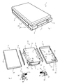
- FIG. 1 an inventive electronic key 1 according to a first embodiment is shown in a perspective view
- FIG. 2 an individual perspective view of the electronic key 1 shows.
- the electronic key 1 is used for a keyless activation of a locking device of a motor vehicle and has a cover 2, which is formed for the illustrated first embodiment of a first cover shell 3 and a second cover shell 4.
- the electronic key 1, as in the Figures 1 and 2 can be seen, in each case on its longitudinal sides 9 an elastic key element 5.
- the two key elements 5 offer different functions, such as opening and locking a closure device of the motor vehicle or the opening of the trunk.
- the two key elements 5 are arranged laterally on the electronic key 1.
- first cover shell 3 and the second cover shell 4 which together form the cup-shaped cover 2, of a functional body 6, which is part of the electronic key 1, disassembled.
- the two cover shells 3 and 4 are of identical construction, so that the in FIG. 2 Given plan view of the first cover shell 3 is synonymous with a plan view of the second cover shell 4. Likewise, the in FIG. 2 given view of the underside of the second cover shell 4 synonymous with a view of the underside of the first cover shell 3. Due to the design similarity is therefore omitted a top view of the second cover shell 4 and a bottom view of the first cover shell 3.
- the first cover shell 3 covers the upper side 7 of the functional body 6 over the entire area
- the second cover shell 4 covers the underside 8 of the functional body 6 over its entire area.
- the cover 2 which is formed by at least one of the cover shells 3 or 4, covering the entire surface of the top 7 and / or the bottom 8 of the functional body 6.
- the second cover shell 4 could also be fastened on the upper side 7 and the first cover shell 3 on the lower side 9 of the functional body.
- the functional body 6 is formed housing-shaped and serves to accommodate electrical and electronic components, which are set up for keyless activation of the locking device of the motor vehicle.
- the key elements 5 are mounted on the functional body 6 and are operatively connected to switches of the electrics and / or electronics arranged in the interior of the functional body 6, sealing elements, not shown, interspacing between the key elements 5 and the interior of the Seal functional body 6 so that no moisture can penetrate into the interior of the functional body 6.
- the two key element 5, which extends from a first end face 10 of the functional body 6 to a second end face 11 of the functional body 6, are fastened on a respective longitudinal side 9 of the functional body 6 connecting the upper side 7 with the lower side 8.
- the key element 5 may alternatively also have a plurality of keys, which may be attached to the longitudinal sides 9 of the functional body 6.
- the item view in FIG. 2 shows further that due to the cup-shaped design, the two cover shells 3 and 4 have at their respective outer edge a collar 34 which is at least partially adapted to the outer contour of the functional body 6.
- This collar 34 surrounds the outer contour of the functional body 6 such that only a section-wise region of the second end face 11 is visible from the outside.
- the cover shells 3, 4 surround the functional body 6 except for the region of the longitudinal sides 9 and the second end face 11 substantially gapless and sealing, in particular the top and bottom 7, 8 of the functional body 6 is sealingly surrounded by the cover shells 3, 4 ,
- the inventive electronic key 1 is shown in each case in a lateral sectional view, wherein the representations each show an enlargement of the area of the second end face 11.
- the runs in FIG. 5 shown section through a first sliding element 12, whereas the in FIG. 6 section shown by a second sliding element 13 extends.
- the representations of the FIGS. 3 to 7 Parts of a locking mechanism 14 (see FIG. 7 ), through which the cover 2 formed by the first cover shell 3 and the second cover shell 4 detachably attached to the functional body 6 of the electronic key 1 according to the first embodiment attached and locked.
- the locking mechanism 14 comprises at least one hooking connection 15 and at least one positive connection 16, which is designed in the manner of a clamping connection.
- FIG. 7 On the left half is a sectional view in the vicinity of a longitudinal side 9 of the functional body 6 and a longitudinal side 19 of the cover shells 3, 4 shown to more detail the hook connection 15, which is arranged and formed in the first embodiment on the longitudinal sides 9 of the functional body 6.
- a respective hooking connection 15 is formed by a locking rib 17 and a receptacle 18.
- a respective locking rib 17 is integrally formed on a longitudinal side 9 of the functional body 6 and is laterally from the functional body 6 from.
- each one longitudinal side 9 of the functional body 6 thus four locking ribs 17 are formed, as the Figures 2 and 4 can be seen.
- Each one of the two cover shells 3, 4 has corresponding receptacles 18 for the locking ribs 17, in particular from the FIG. 2 evident.
- a respective cover shell 3, 4 on each of its longitudinal sides 19 two receptacles.
- the locking ribs 17 of the functional body 6 have a first end face 10 sloping inclined locking surface 20 (see FIG. 7 ), which for attachment of the cover shells 3, 4 with the correspondingly shaped in the cover shells 3, 4 receptacles 18, each having a locking surface 21, which is also inclined to the first end 10 to fall down, cooperate.
- the locking surfaces 20 of the functional body 6 and the locking surfaces 21 of the cover shells 3, 4 are wedged with each other on the functional body 6 fixed cover shell 3 or 4.
- a respective cover shell 3 4 corresponding locking ribs 17 are inserted into the receptacles 18 of the corresponding cover shell 3, 4, as in FIG. 8 in the left illustration is shown.
- the first cover shell 3 is placed on the top 7 of the functional body 6, as indicated by the arrow A.
- the second cover shell 4 which is placed from below on the bottom 8 of the functional body 6, as indicated by the arrow B in FIG. 8 is indicated.
- the receptacles 18 of the cover shells 3, 4 are aligned such that the locking ribs 17 dive into the associated receptacles 18 and are inserted.
- a corresponding force must act in the direction of the second end face 11, which is effected by the user and by the arrows C and D in FIG. 8 is shown.
- the respective clamping lugs 22 come into abutment with the associated clamping webs 3, whereby positive connections 16 are made on the second end face 11, as will be described in more detail below.
- the positive connection 16 for fastening the first cover shell 3 to the functional body 6 has a clamping attachment 22, which is arranged on the second end face 11 of the functional body 6, and a clamping web 23, each at the disposed on the second end face 11 longitudinal end 24 of the cover shell 3 is formed on (see, for example FIGS. 5 and 7 ).
- the locking ribs 17 of the functional body 6 are first in the associated receptacles 18 of the corresponding cover shell 3, 4 (see FIGS. 7 and 8th ), as previously described. Subsequently, the first cover shell 3 is moved or pressed in the direction of the second end face 11 of the functional body 6 (see the direction of the arrow C in FIG FIG.
- clamping collar 22 and clamping bar 23 corresponds to a locking position.
- first outer shell 3 Due to the clamping effect present between clamping web 23 and clamping jaw 22, which extends over a certain clamping height in the direction of upper side 7 to lower side 8 of functional body 6, it is essentially not possible for first outer shell 3 to be arranged on second end side 11 of functional body 6 can be moved away from the top 7. This is only possible if the clamping web 23 and the clamping collar 22 are disengaged, i. when the clamping collar 22 no longer presses the clamping web 23 in the direction of the second end face 11.
- the tension of the cover shell 3 is repealed by the clamping collar 22 is moved transversely to the longitudinal side 6 of the functional body 6 until the clamping web 23 of the cover shell 3 can move in the direction of the first end face 10 and the clamping attachment 22 this movement gets in the way.
- the first sliding element 12 has to be provided in a corner region of the second end face 11 of the functional body 6 and attached there to the functional body 6 , be operated.
- the first sliding element 12 comprises a parallelepiped-shaped body 26 on which the clamping attachment 22 is formed and from which the elastic restoring element 25 protrudes laterally, a sliding button 28 and a connecting web 27 which connects the block-shaped body 26 to the sliding button 28.
- the individual parts of the multi-part sliding element 12 are assembled only when the sliding element 12 is mounted on the functional body 6 and before the first cover shell 3 is fastened.
- a first receiving recess 29 (see, for example FIG. 2 or FIG. 4 ) is provided, which extends from the top 7 in the direction of the bottom 8 of the functional body 6.
- the elastic return element 25 In the first receiving recess 29 of the cuboid body 26 is used with the elastic return element 25.
- the connecting bar 27 through a first passage opening 31 which is formed in the second end face 11 of the functional body 6, passed and fixedly connected to the cuboid body 26.
- the connecting web 27 may already be the sliding button 28 is attached, or it is attached to the connecting web 27.
- the first sliding element 12 for disassembling the first cover shell 3 must be moved by the user from the locking position against the force of the elastic return element 25 in the release position.
- the elastic return element 25 is formed in the illustrated first embodiment as a compression spring and holds the first sliding element 12 in the locking position, as long as no counterforce is applied by the user to release the first cover shell 3 from the functional body 6.
- the first sliding element 12 is in the first receiving recess 29 (see Figures 2 . 4 and 5 ) housed, which is formed on the second end face 11 of the functional body 6. In the first receiving recess 29, the first sliding member 12 is then slidably movable against the force of the elastic return element 25 between the locking position and the release position.
- the clamping collar 22 is relative to the clamping web 23 against the force of the elastic return element 25 from the locking position, in which the at least one clamping collar 22 rests against the clamping web 23 and this in the direction of the first End face 10 of the functional body 6 presses, in a release position in which the at least one clamping attachment 22 releases the at least one clamping web 23, is designed to be movable.
- the positive connection 16 ensures that the first cover shell 3 is attached to the functional body 6 in a tensioning manner by the clamping collar 22 presses against the clamping web 23.
- the electronic key 1 can only be provided with a single cover shell 3, so that the assembly and disassembly of the (first and) single cover shell 3 can be carried out as described above.
- the underside 8 of the functional body 6 is covered over the entire surface, in addition to the top surface 7 covered by the first cover shell 3 over the whole area, for which purpose the second cover shell 4 is used.
- the locking mechanism 14 of the electronic key 1 of the first embodiment a further hooking 15 on the first end face 10 and another positive connection 16 at the second end face 11 includes, but now formed between the second cover shell 4 and the functional body 6 on the underside 8, such as for example FIG.
- the second sliding element 13 is provided, which is arranged in the other corner region of the second end face 11.
- the second sliding element 13 is constructed identical to the first sliding element 12, as the FIG. 2 can be seen. Due to the identical design of cover shells 3, 4 and sliding elements 12, 13 results in a cost-effective production of the electronic key 1. In FIG. 2 the second sliding element 13 is compared to the first sliding element 12 only rotated by 180 ° and is literally upside down. Due to the identical construction, the second sliding element 13 is described only briefly and instead refer to the detailed explanations of the first sliding element 13.
- the cuboid body of the second sliding element 13 is in a second receiving recess 30 is inserted, which in contrast to the first receiving recess 29 now extends from the bottom 8 of the functional body 6 in the direction of the top 7, as in particular in the FIG. 4 can be seen, which shows a section in the region of the second end face 11 of the functional body 6 through the first and second receiving recess 29, 30.
- a second passage opening 32 is provided to connect the cuboid body 26 with the outside of the functional body 6 arranged shift key 28.
- the positive connection 16 between the second sliding element 12 and the second cover shell 4 is formed substantially identical to the positive connection 16 between the first sliding element 11 and the first cover shell 3, wherein also a similar operation for fixing and dismounting the cover shell 4 is given , so that reference can be made to the corresponding explanations for the first cover shell 3.
- the elastic return element 25 of the second sliding element 13 is likewise designed as a compression spring and holds the second sliding element 13 in the locking position, in which the second cover shell 4 is fastened to the functional body 6. Only when a force is applied by a user against the force of the elastic return element 25, whereby the second slide switch 13 is moved in the direction of the first slide switch 12, the second cover shell 4 can be detached from the functional body 6 and removed.
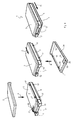
- FIGS. 9 to 14 show an electronic key 101 according to the invention according to a second embodiment and details and individual components of the key 101, which also serves a closing device of a motor vehicle and having a cover 102 which is formed by a first cover shell 103 and a second cover shell 104.
- the electronic key 101 of the second embodiment has, like the first embodiment, elastic key elements 105 attached to a functional body 106 of the electronic key 101. With regard to conceivable functions of the key elements 105, reference is made to the comments on the first embodiment.
- the two cover shells 103 and 104 are in turn designed to be identical, so that the in FIG.
- the first cover shell 103 covers the upper side 107 of the functional body 6 over the entire surface
- the second cover shell 104 covers the underside 108 of the functional body 6 over its entire surface. Due to the identical construction of the two cover shells 103, 104 and the first cover shell 103 can be attached to the bottom 108 and the second cover shell 104 at the top 107 of the functional body 106.
- the key elements 105 further extend from a first end face 110 to a second end face 111 of the housing-shaped functional body 106, wherein the key elements 105 are mounted on a respective longitudinal side 109 of the functional body 106.
- a respective key element 105 of the second embodiment may alternatively consist of a plurality of keys.
- FIG. 13 the inventive electronic key 101 according to the second embodiment is shown in a perspective sectional view.
- This view of the electronic key 101 can be seen from a locking mechanism 114, by means of which the cover 102 formed by the first cover shell 103 and the second cover shell 104 is detachably attached and locked to the functional body 106.
- the locking mechanism 114 includes a hooking connection 115 and a clamping connection 116.
- the hooking connection 115 is provided on the first end face 110 of the functional body 106 and, in the illustrated embodiment, comprises two recesses 117 (see FIG FIG. 12 ), which are formed on the first end face 110 of the functional body 106, and corresponding to the recesses 117 formed plug lugs 118 (see, for example FIG.
- the respective insertion lugs 118 of the cover shells 103, 104 are introduced into the recesses 117 of the functional body 106 in order to produce the hooking connection 115.
- the hooking connection 115 can be formed by at least one recess 117 formed on the first end side 110 of the functional body 106 and by at least one plug-in projection 118, wherein the at least one plug-in projection 118 on the first End face 119 is formed on at least one cover shell 103, 104.
- the clamping connection 116 is then produced, as by FIG. 14 is clarified.
- the clamping connection 116 is provided on the second end face 111 of the functional body 106 and designed such that it urges the cover shells 103 and 104 in the direction of the second end face 111 of the functional body 106 and thereby pushes the insertion lugs 118 of the cover shells 103, 104 into the corresponding recess 117 ,
- the clamping connection 116 has a clamping attachment 120, which is arranged on the second end face 111 of the functional body 106, and a clamping web 121, which is respectively formed on the end face of the cover shells 103 and 104 opposite the first end face 119.
- the respective insertion lugs 118 (see, for example FIG. 13 ) is first introduced into the recesses 117 of the functional body 6, as already described above. Subsequently, the end faces 119 of the respective cover shells 103, 104 opposite the first end faces 119 are pivoted in the direction of the second end face 111 of the functional body 106 (see arrow E in FIG FIG. 14 ), until the respective clamping bar 121 of each cover shell 103, 104 rests on the associated clamping attachment 120 in a clamping manner such that the clamping attachment 120 presses the corresponding cover shell 103, 104 in a direction away from the first end face 110 of the functional body 106.
- clamping lug 120 and clamping bar 121 corresponds to the locking position. Due to the clamping effect between the clamping web 121 and clamping attachment 120 or cover shell 103 or 104, it is not possible for the cover shells 103, 104 on the second end face 111 of the functional body 106 to be moved away from the upper side 107 or from the lower side 108. This is only possible if the clamping bar 121 and the clamping collar 120 are disengaged, ie when the clamping collar 120 no longer blocks the clamping bar 121. As especially the FIG.
- a sliding element 124 provided on the second end face 111 of the functional body 106 must be actuated by a user when the first and second cover shell 103, 104 are locked on the functional body 106.
- the sliding element 124 has the clamping lug 120 and is displaceably movable in the direction of the first end face 110 of the functional body 106 between the locking position and a release position, in which the clamping lug 120 is brought out of engagement with the clamping web 121.
- the sliding element 124 is substantially I-shaped in cross-section (see, for example FIG. 13 ) and has a central web 125 which is coupled for movement with a shift key 126. Again FIG.
- the slide button 126 has elastic and hook-shaped coupling arms 140 which engage with the I-shaped slide member 124, wherein the hook-shaped ends of the coupling arms 140 are inserted through an opening 141 of the sliding member 124 and a decoupling of the sliding element 124 prevent.
- the longitudinal ends 127 and 128 of the central web 125 are arranged on top and bottom 107, 108 of the functional body 106. At a respective longitudinal end 127 or 128 are transverse to the central web 125 of the clamping collar 120 and oppositely directed serving for fixing the sliding member 124 on the functional body 106 locking projection 129 formed.
- a respective latching projection 129 of the I-shaped sliding element 124 is hook-shaped and engages behind a locking projection 130 formed on the functional body 106, wherein the clamping attachment 120 of the I-shaped sliding element 124 is arranged in the manner of a bolt in the receiving pocket 122 of a corresponding cover shell 103, 104 and prevents the corresponding cover shell 103, 104 from being moved away from the functional body 106.
- the sliding button 126 is externally manageable for a user by pushing the sliding button 126 or sliding element 124 toward the first end face 110 of the functional body 106, where the user wants to move the sliding element 124 against the force of an elastic return element 131 solve the positive connections 116 for the first and second cover shell 103, 104 or even for only one of the two cover shells 103 or 104.
- the clamping device 121 By pressing the sliding element 124 in the direction of the first end face 110 of the functional body 106, the clamping device 121, which acts in the manner of a bolt, is brought out of engagement with the clamping web 121 and thus passes out of the receiving pocket 122 of the cover shell 103, 104, so that the cover shell 103, 104 can be pivoted away from the functional body 106 for disassembly.
- the elastic return element 131 is inserted into an opening in the second end face 111 of the functional body 106 and is arranged in extension of the sliding button 126 and in its operating direction.
- the sliding button 126 is in any case to operate when disassembling a cover shell 103, 104, because the second embodiment provides only a single slide button 126, with both the first cover shell 103 and the second cover shell 104 (together or separately or only one of both) can be released from the functional body 106.
- the one single shift key 126 in the second embodiment is no longer arranged in a corner area but centrally on the second end face 111 of the functional body 106.
Abstract
Bei einem elektronischen Schlüssel (1; 101), der einen zur Unterbringung von elektrischen und elektronischen Bauteilen dienenden und gehäuseförmig ausgebildeten Funktionskorpus (6; 106) und zumindest ein Tastenelement (5; 105), das an dem Funktionskorpus (6; 106) angebracht ist, aufweist, soll eine Lösung geschaffen werden, durch die auf konstruktiv einfache Weise ein elektronischer Schlüssel bereitgestellt wird, der einen besseren Komfort und zugleich eine einfache sowie einwandfreie Bedienung gewährleistet. Dies wird dadurch erreicht, dass eine Abdeckung (2; 102) mittels einer Arretierungsmechanik (14; 114) lösbar am Funktionskorpus (6; 106) arretiert ist und zumindest die Oberseite (7; 107) und/oder die Unterseite (8; 108) des Funktionskorpus (6; 106) vollflächig abdeckt.An electronic key (1; 101) having a functional body (6; 106) designed to house electrical and electronic components and shaped like a housing, and at least one key element (5; 105) attached to the functional body (6; 106) , A solution is to be created by the structurally simple way an electronic key is provided, which ensures better comfort and at the same time a simple and flawless operation. This is achieved in that a cover (2, 102) is releasably locked to the functional body (6, 106) by means of a locking mechanism (14, 114) and at least the upper side (7, 107) and / or the lower side (8, 108). the functional body (6, 106) covers the entire surface.
Description
Die Erfindung richtet sich auf einen elektronischen Schlüssel, aufweisend einen zur Unterbringung von elektrischen und elektronischen Bauteilen dienenden und gehäuseförmig ausgebildeten Funktionskorpus und zumindest ein Tastenelement, das an dem Funktionskorpus angebracht ist.The invention is directed to an electronic key, comprising a functional body which is used to accommodate electrical and electronic components and has a housing-shaped design, and at least one key element which is attached to the functional body.
Ein elektronischer Schlüssel der eingangs bezeichneten Art ist beispielsweise aus der
Der Erfindung liegt die Aufgabe zugrunde eine Lösung zu schaffen, die auf konstruktiv einfache Weise und kostengünstig einen elektronischen Schlüssel bereitstellt, der einen besseren Komfort und zugleich eine einfache sowie einwandfreie Bedienung gewährleistet.The invention has for its object to provide a solution that provides an electronic key in a structurally simple manner and cost, which ensures better comfort and at the same time a simple and flawless operation.
Bei einem elektronischen Schlüssel der eingangs bezeichneten Art wird die Aufgabe erfindungsgemäß dadurch gelöst, dass eine Abdeckung mittels einer Arretierungsmechanik lösbar am Funktionskorpus arretiert ist und zumindest die Oberseite und/oder die Unterseite des Funktionskorpus vollflächig abdeckt.In an electronic key of the type described, the object is achieved in that a cover by means of a locking mechanism is releasably locked to the functional body and covers at least the top and / or bottom of the functional body over the entire surface.
Vorteilhafte und zweckmäßige Ausgestaltungen und Weiterbildungen der Erfindung ergeben sich aus den Unteransprüchen.Advantageous and expedient refinements and developments of the invention will become apparent from the dependent claims.
Durch die Erfindung wird ein elektronischer Schlüssel zur Verfügung gestellt, welcher sich durch eine einfache und kompakte Bauweise bei gleichzeitiger Bedienung mit einem hohen Komfort auszeichnet. Die Abdeckung dient dazu, den Funktionskorpus und daran oder auch darin angebrachte Bauteile vor Beschädigung zu schützen. Im Gegensatz zu aus dem Stand der Technik bekannten Abdeckungen oder Batteriefachdeckeln deckt die Abdeckung vollflächig die Oberseite und/oder Unterseite des Funktionskorpus ab, wodurch sie dem erfindungsgemäßen elektronischen Schlüssel ein exklusives und hochwertiges Erscheinungsbild verleiht. Mit Hilfe der Arretierungsmechanik ist darüber hinaus die Abdeckung problemlos und ohne große Kraftanstrengung von dem Funktionskorpus abnehmbar, um beispielsweise Zugriff auf einen am Funktionskorpus angebrachten mechanischen Notschlüssel oder auf ein Batteriefach zu erhalten. Die Arretierungsmechanik gestattet aber auch einen komfortablen Austausch der Abdeckung, was nicht nur im Fall einer Beschädigung der Abdeckung erwünscht sein muss. Zum Beispiel kann ein Austausch der Abdeckung auch gewünscht sein, um dem elektronischen Schlüssel insgesamt ein neues und aktuelles optisches Erscheinungsbild zu geben.By the invention, an electronic key is provided, which is characterized by a simple and compact design with simultaneous operation with a high level of comfort. The cover serves to protect the functional body and attached thereto or components therein from damage. In contrast to known from the prior art covers or battery compartment covers the cover covers the entire surface of the top and / or bottom of the functional body, thereby giving the electronic key according to the invention an exclusive and high-quality appearance. With the help of the locking mechanism beyond the cover is easily removed without much effort from the functional body to get, for example, access to a mounted on the functional body mechanical emergency key or on a battery compartment. But the locking mechanism also allows a comfortable replacement of the cover, which must be desirable not only in the event of damage to the cover. For example, replacement of the cover may also be desired to give the electronic key overall a new and up-to-date visual appearance.
Die Erfindung sieht in Ausgestaltung des elektronischen Schlüssels vor, dass die Abdeckung wenigstens eine zur vollflächigen Abdeckung der Oberseite oder der Unterseite dienend ausgebildete Deckschale oder dass die Abdeckung eine die Oberseite des Funktionskorpus vollflächig abdeckende erste Deckschale und eine die Unterseite des Funktionskorpus vollflächig abdeckende zweite Deckschale aufweist. Die Abdeckung kann somit von wenigstens zwei Deckschalen gebildet sein, wodurch es möglich ist, dass nur eine der beiden Deckschalen von dem Funktionskorpus gelöst wird und die andere Deckschale die Ober- oder Unterseite des Funktionskorpus nach wie vor abdeckt und damit schützt. Durch die schalenförmige Ausbildung weisen die wenigstens zwei Deckschalen an ihrem jeweiligen äußeren Rand einen Kragen auf, welcher zumindest abschnittsweise der Außenkontur des Funktionskorpus angepasst ist und diese derart umgreift, dass nur Bereiche der Längsseiten des Funktionskorpus von außen zugänglich sind, wobei die Deckschalen bis auf den Bereich der Längsseiten den Funktionskorpus spaltlos und dichtend umgeben.The invention provides in an embodiment of the electronic key, that the cover at least one for full-surface coverage of the top or the bottom serving cover shell or that the cover has a the top of the functional body over the entire surface covering the first cover shell and the underside of the functional body over the entire surface covering the second cover shell. The cover can thus be formed by at least two cover shells, whereby it is possible that only one of the two cover shells is released from the functional body and the other cover shell still covers the top or bottom of the functional body and thus protects. Due to the cup-shaped design, the at least two cover shells at their respective outer edge on a collar which is at least partially adapted to the outer contour of the functional body and this encompasses such that only portions of the longitudinal sides of the functional body are accessible from the outside, the cover shells except for Area of the long sides of the functional body surrounded gapless and sealing.
Bei einer Anordnung des Tastenelementes auf der Ober- und/oder Unterseite eines gehäuseartig ausgebildeten Schlüssels des Standes der Technik kommt es immer wieder zu einer ungewünschten Betätigung einer Taste, insbesondere wenn der aus dem Stand der Technik bekannte Schlüssel zum Beispiel in der Hosentasche mittransportiert wird. Auch stellt die Befestigung der Tastenelemente insbesondere dann ein Problem dar, wenn die Batterie des elektronischen Schlüssels getauscht oder wenn auf einen im oder am Gehäuseelement angebrachten Notschlüssel zugegriffen werden soll, denn hierbei besteht in beiden Fällen die Gefahr, dass sich einzelne Tasten vom Gehäuseelement lösen können. Aus diesem Grund ist in weiterer Ausgestaltung des elektronischen Schlüssels erfindungsgemäß vorgesehen, dass das zumindest eine Tastenelement auf einer der beiden die Oberseite mit der Unterseite verbindenden Längsseiten des Funktionskorpus befestigt ist. Dadurch, dass ein jeweiliges Tastenelement auf den Längsseiten des Funktionskorpus und nicht wie im Stand der Technik auf Ober- und/oder Unterseite des gehäuseartig ausgebildeten Funktionskorpus angeordnet und angebracht ist, wird eine unbeabsichtigte Betätigung der Tasten vermieden. Insbesondere wird durch die Anordnung der Tasten an den Längsseiten (oder auch nur an einer Längsseite) des Funktionskorpus auf der Oberseite und/oder der Unterseite des Funktionskorpus Platz geschaffen, der zur Anbringung von anderen Elementen genutzt werden kann. Die erfindungsgemäße Anordnung der Deckschalen ermöglicht eine Betätigung des wenigstens einen Tastenelements und gibt dieses frei, so dass es vor Betätigung des Tastenelements nicht notwendig ist, zum Beispiel eine Abdeckung des Tastenelements zu entfernen. Jedoch liegen die Deckschalen derart an dem wenigstens einen Tastenelement an, dass der Funktionskorpus insgesamt spaltlos bzw. spaltfrei und dichtend von den Deckschalen umgeben ist.In an arrangement of the key element on the top and / or bottom of a housing-like key of the prior art, it always comes back to an unwanted operation of a button, especially if the known from the prior art key, for example, in the pocket is transported. Also, the attachment of the key elements in particular is a problem when the battery of the electronic key exchanged or if you want to access an attached in or on the housing element emergency key, because this is in both cases the risk that individual keys can be detached from the housing element , For this reason, in a further embodiment of the electronic key according to the invention, it is provided that the at least one key element is fastened on one of the two longitudinal sides of the functional body connecting the upper side with the underside. Characterized in that a respective key element on the longitudinal sides of the functional body and not as in the prior art on the top and / or bottom of the housing-like functional body is arranged and mounted, an unintentional operation of the keys is avoided. In particular, by the arrangement of the buttons to the Long sides (or even only on one longitudinal side) of the functional body on the top and / or the bottom of the functional body created space that can be used for attaching other elements. The inventive arrangement of the cover shells allows actuation of the at least one key element and releases it so that it is not necessary to remove a cover of the key element prior to actuation of the key element. However, the cover shells abut against the at least one key element in such a way that the functional body as a whole is surrounded gap-free or gap-free and sealingly by the cover shells.
Die Erfindung sieht in weiterer Ausgestaltung des elektronischen Schlüssels vor, dass die Arretierungsmechanik wenigstens eine an einer ersten Stirnseite und/oder an zumindest einer Längsseite des Funktionskorpus angeordnete Einhakverbindung und wenigstens eine an der zweiten Stirnseite des Funktionskorpus angeordnete formschlüssige Verbindung umfasst, durch welche wenigstens eine Deckschale am Funktionskorpus in verspannender Weise lösbar angebracht ist. Gemäß der Erfindung wird zur Anbringung einer jeweiligen Deckschale zunächst die Einhakverbindung zwischen Funktionskorpus und der entsprechenden Deckschale hergestellt, bevor dann im Anschluss daran die Deckschale mit Hilfe der Klemmverbindung an dem Funktionskorpus arretiert wird.The invention provides in a further embodiment of the electronic key that the locking mechanism comprises at least one arranged on a first end side and / or on at least one longitudinal side of the functional body hooking and at least one arranged on the second end side of the functional body form-fitting connection through which at least one cover shell is releasably attached to the functional body in a tightening manner. According to the invention, the hooking connection between the functional body and the corresponding cover shell is first produced for attaching a respective cover shell, before the cover shell is subsequently locked to the functional body by means of the clamping connection.
Hinsichtlich einer konstruktiv einfachen Möglichkeit zur Ausgestaltung der Klemmverbindung sieht die Erfindung in Weiterbildung vor, dass die wenigstens eine formschlüssige Verbindung von zumindest einem an der zweiten Stirnseite des Funktionskorpus angeordneten Klemmansatz und von zumindest einem Klemmsteg gebildet ist, wobei der Klemmsteg in Nähe eines Längsendes der wenigstens einen Deckschale ausgebildet ist, das an der zweiten Stirnseite des Funktionskorpus angeordnet ist, und wobei der zumindest eine Klemmansatz relativ zu dem zumindest einen Klemmsteg gegen die Kraft eines elastischen Rückstellelements aus einer Arretierungsposition, in welcher der zumindest eine Klemmansatz an dem zumindest einen Klemmsteg anliegt und eine Relativbewegung zwischen Klemmsteg und Klemmansatz verhindert, in eine Freigabeposition, in welcher der zumindest eine Klemmansatz den zumindest einen Klemmsteg freigibt, bewegbar ausgebildet ist. Auf diese Weise wird eine jeweilige Deckschale an dem Funktionskorpus arretiert, indem zunächst der Steckansatz der Deckschale mit der Ausnehmung im Funktionskorpus in Eingriff gebracht wird, bevor der Klemmansatz des Funktionskorpus gegen den Klemmsteg drückt und diesen in eine dem Steckansatz abgewandte Richtung drängt, um die Deckschale an dem Funktionskorpus zu arretieren.With regard to a structurally simple way to design the clamping connection, the invention provides in a further development that the at least one positive connection of at least one arranged on the second end face of the functional body clamping jaw and at least one clamping web is formed, wherein the clamping web in the vicinity of a longitudinal end of at least a cover shell is formed, which is arranged on the second end side of the functional body, and wherein the at least one clamping lug relative to the at least one clamping web against the force of an elastic return element from a locking position, in which the at least one clamping lug is applied to the at least one clamping web and a relative movement between the clamping bar and Clamping approach prevents, in a release position, in which the at least one clamping jaw releases the at least one clamping web, is designed to be movable. In this way, a respective cover shell is locked to the functional body by first the plug neck of the cover shell is brought into engagement with the recess in the functional body before the clamping collar of the functional body presses against the clamping web and pushes it in a direction remote from the plug approach to the cover shell to lock on the functional body.
Eine konstruktiv besonders einfache Möglichkeit zur Ausgestaltung der Einhakverbindung ist erfindungsgemäß dadurch gegeben, dass die wenigstens eine Einhakverbindung von wenigstens einer jeweils an einer Längsseite des Funktionskorpus angeformten Verriegelungsrippe und einer der jeweiligen Verriegelungsrippe zugeordneten Aufnahme gebildet ist, wobei die jeweilige zugeordnete Aufnahme an einer Längsseite der entsprechenden Deckschale ausgeformt ist, und wobei die wenigstens eine formschlüssige Verbindung die entsprechende Deckschale in Richtung der zweiten Stirnseite des Funktionskorpus drängend und dadurch die wenigstens eine Verriegelungsrippe in die Aufnahme verriegelnd drückend ausgebildet ist.A structurally particularly simple way of configuring the hooked connection is provided according to the invention in that the at least one hooking connection is formed by at least one locking rib formed on one longitudinal side of the functional body and one receptacle associated with the respective locking rib, the respective associated receptacle being formed on a longitudinal side of the corresponding receptacle Deck shell is formed, and wherein the at least one positive connection, the corresponding cover shell in the direction of the second end side of the functional body urging and thereby the at least one locking rib in the receptacle is designed to be locked pushing.
Zur Lösung der Klemmverbindung an der zweiten Stirnseite des Funktionskorpus sieht die Erfindung in Ausgestaltung dann weiter vor, dass zumindest ein quer zur Längsseite des Funktionskorpus betätigbares Schiebeelement vorgesehen ist, an dem der zumindest eine Klemmansatz ausgebildet ist, wobei der zumindest eine Klemmansatz und damit das zumindest eine Schiebeelement in einer Aufnahmeausnehmung, die an der zweiten Stirnseite des Funktionskorpus ausgeformt ist, untergebracht und in der Aufnahmeausnehmung gegen die Kraft des elastischen Rückstellelements zwischen der Arretierungsposition und der Freigabeposition verschieblich bewegbar ausgebildet ist. Im unbetätigten Zustand des Schiebeelements ist dieses in der Arretierungsposition gehalten, so dass der Klemmansatz gegen den Klemmsteg drückt und insgesamt eine entsprechende Deckschale in klemmender und verspannender Weise an dem Funktionskorpus gehalten ist.To solve the clamping connection on the second end face of the functional body, the invention further provides in an embodiment that at least one transversely to the longitudinal side of the functional body operable sliding element is provided on which the at least one clamping lug is formed, wherein the at least one clamping lug and thus at least a sliding member in a receiving recess, which is formed on the second end face of the functional body, housed and slidably formed in the receiving recess against the force of the elastic return element between the locking position and the release position. In the unactuated state of the sliding element this is held in the locking position, so that the clamping jaw presses against the clamping web and a total of a corresponding cover shell in clamped and tightening manner is held on the functional body.
Bei einem elektronischen Schlüssel mit zwei Deckschalen ist es von besonderem Vorteil, wenn ein erstes Schiebeelement der ersten Deckschale und ein zweites Schiebeelement der zweiten Deckschale zugeordnet ist, wobei das erste und das zweite Schiebeelement jeweils einen Klemmansatz und eine Schiebetaste aufweisen, wobei der Klemmansatz des ersten Schiebeelements in einer ersten, sich von der Oberseite in Richtung der Unterseite des Funktionskorpus erstreckenden Aufnahmeausnehmung angeordnet ist und mit der außerhalb des Funktionskorpus angeordneten Schiebetaste des ersten Schiebeelements bewegungsgekoppelt ist, und wobei der Klemmansatz des zweiten Schiebeelements in einer zweiten, sich von der Unterseite in Richtung der Oberseite des Funktionskorpus erstreckenden Aufnahmeausnehmung angeordnet ist und mit der außerhalb des Funktionskorpus angeordneten Schiebetaste des zweiten Schiebeelements bewegungsgekoppelt ist. Auf diese Weise sind beide Deckschalen unabhängig voneinander von dem Funktionskorpus lösbar, so dass auch nur eine einzige Deckschale entfernt werden kann, während die andere Deckschale weiterhin am Funktionskorpus fest angebracht ist und sich nicht löst, wenn die andere Deckschale demontiert wird.In an electronic key with two cover shells, it is of particular advantage if a first sliding element of the first cover shell and a second sliding element of the second cover shell is assigned, wherein the first and the second sliding element each have a clamping attachment and a sliding button, wherein the clamping attachment of the first Sliding element is arranged in a first, extending from the upper side in the direction of the underside of the functional body receiving recess and is coupled to the outside of the functional body arranged shift key of the first sliding element, and wherein the clamping attachment of the second sliding element in a second, from the bottom in the direction the upper side of the functional body extending receiving recess is arranged and is movably coupled to the outside of the functional body arranged shift key of the second sliding element. In this way, both cover shells are independently detachable from the functional body, so that only a single cover shell can be removed, while the other cover shell is still firmly attached to the functional body and does not dissolve when the other cover shell is dismantled.
Im Hinblick auf eine ergonomische Handhabung des elektronischen Schlüssels zur Demontage der Deckschalen ist in Ausgestaltung der Erfindung vorgesehen, dass das erste Schiebeelement in einem Eckbereich der zweiten Stirnseite des Funktionskorpus angeordnet ist und das zweite Schiebelement in einem dem ersten Schiebeelement gegenüberliegenden Eckbereich des Funktionskorpus angeordnet ist, wobei das erste und zweite Schiebelement aufeinander zu bewegbar ausgebildet sind. Der elektronische Schlüssel kann somit bequem in der Handfläche eines Benutzers gehalten werden, wobei zum Lösen einer Deckschale dann der Benutzer beispielsweise mit dem Daumen derselben Hand das Schiebeelement betätigen und in Richtung des anderen Schiebeelements bewegen kann, wodurch der mit dem Schiebeelement bewegungsgekoppelte Klemmansatz außer Anlage zu dem Klemmsteg gelangt, so dass die Deckschale nicht weiter verspannt an dem Funktionskorpus gehalten ist, sondern von dem Funktionskorpus gelöst und demontiert werden kann.With regard to an ergonomic handling of the electronic key for dismantling the cover shells, it is provided in an embodiment of the invention that the first sliding element is arranged in a corner region of the second end side of the functional body and the second sliding element is arranged in a corner region of the functional body opposite the first sliding element, wherein the first and second sliding element are designed to be movable towards each other. The electronic key can thus be conveniently held in the palm of a user, for releasing a cover then the user can operate, for example with the thumb of the same hand, the sliding element and move in the direction of the other sliding element, whereby the motion-coupled with the sliding element clamping attachment out of investment the clamping bar passes, so that the cover shell does not continue braced on the functional body is held, but can be solved and dismantled from the functional body.
Eine alternative Möglichkeit zur Ausgestaltung der Einhakverbindung, die aber ebenfalls konstruktiv besonders einfach ist, besteht erfindungsgemäß darin, dass die Einhakverbindung von wenigstens einer an der ersten Stirnseite des Funktionskorpus ausgeformten Ausnehmung und von wenigstens einem Steckansatz gebildet ist, wobei der wenigstens eine Steckansatz an der ersten Stirnseite an zumindest einer Deckschale ausgebildet ist, und wobei die Klemmverbindung zumindest eine Deckschale in Richtung der zweiten Stirnseite des Funktionskorpus drängend und dadurch den wenigstens einen Steckansatz in die wenigstens eine Ausnehmung drückend ausgebildet istAn alternative possibility for the design of the hooking, but also structurally particularly simple, according to the invention is that the hooking of at least one formed on the first end face of the functional body recess and at least one plug-neck is formed, wherein the at least one plug-in approach to the first End face is formed on at least one cover shell, and wherein the clamping connection at least one cover shell in the direction of the second end face of the functional body urging and thereby the at least one plug-in projection in the at least one recess is formed oppressive
Ebenfalls ergonomisch günstig im Hinblick auf die Handhabung des elektronischen Schlüssels ist es, wenn ein an der zweiten Stirnseite angeordnetes Schiebeelement vorgesehen ist, welches den zumindest einen Klemmansatz aufweist und gegen die Kraft des elastischen Rückstellelements zwischen der Arretierungsposition und der Freigabeposition in Richtung der ersten Stirnseite verschieblich bewegbar ausgebildet ist.It is also ergonomically favorable with regard to the handling of the electronic key when a sliding element arranged on the second end side is provided which has the at least one clamping attachment and is displaceable against the force of the elastic restoring element between the locking position and the release position in the direction of the first end side is designed to be movable.
Aus Gründen der Kostenersparnis und der Bauteilreduzierung kann entsprechend einer Ausgestaltung der Erfindung auf ein zweites Schieberelement bei zwei Deckschalen verzichtet werden, wenn das Schiebeelement I-förmig ausgebildet ist, wobei der Mittelsteg des I-förmigen Schiebeelements, insbesondere mittig, mit einer Schiebetaste bewegungsgekoppelt ist und an seinem jeweiligen an Ober- oder Unterseite des Funktionskorpus angeordneten Längsende quer zu diesem der Klemmansatz und dazu entgegengesetzt ein zur Fixierung des Schiebeelements an dem Funktionskorpus dienender Rastansatz angeformt sind. Das Schiebeelement, welches I-förmig ausgebildet ist, umgreift mit seinen an den Längsenden ausgebildeten Rastansätzen quasi das zweite Stirnende des Funktionskorpus, so dass das Schiebeelement mit den Rastansätzen nach Art einer Klammer an dem Funktionskorpus lösbar befestigbar ist. Über die Schiebetaste ist dann das Schiebeelement handhabbar, um die formschlüssige Verbindung zur Demontage einer Deckschale aufzuheben.For reasons of cost savings and component reduction can be dispensed according to an embodiment of the invention to a second slider element with two cover shells, when the sliding element is I-shaped, wherein the central web of the I-shaped sliding element, in particular centrally, is motion-coupled with a slide button and are arranged at its respective arranged at the top or bottom of the functional body longitudinal end transversely to this of the clamping collar and to the opposite serving for fixing the sliding element to the functional body latching projection. The sliding element, which is of I-shaped design, engages with its latching lugs formed at the longitudinal ends, as it were, the second front end of the functional body, so that the sliding element with the latching lugs can be releasably secured to the functional body in the manner of a clamp. About the sliding button then the sliding element is manageable to pick up the positive connection for disassembly of a cover shell.
Konstruktiv besonders günstig ist es schließlich in weiterer Ausgestaltung der Erfindung, wenn ein jeweiliger Rastansatz des I-förmigen Schiebeelements hakenförmig ausgebildet ist und einen am Funktionskorpus ausgebildeten Rastvorsprung hintergreift, wobei der Klemmansatz des I-förmigen Schiebeelements in einer Aufnahmetasche einer entsprechenden Deckschale angeordnet ist, wobei eine Seitenwandung der Aufnahmetausche der Klemmsteg der entsprechenden Deckschale ist. Der Klemmansatz entspricht somit bei hergestellter formschlüssiger Verbindung einer Art Riegel, der in die Aufnahmetasche eingeschoben ist und damit die Deckschale fixiert.Finally, it is structurally particularly favorable in a further embodiment of the invention when a respective latching lug of the I-shaped sliding element is hook-shaped and engages behind a locking projection formed on the functional body, wherein the clamping lug of the I-shaped sliding element is arranged in a receiving pocket of a corresponding cover shell, wherein a side wall of the receiving exchanges the clamping web of the corresponding cover shell is. The clamping attachment thus corresponds to a form-locking connection produced a kind of latch which is inserted into the receiving pocket and thus fixes the cover shell.
Es versteht sich, dass die vorstehend genannten und nachstehend noch zu erläuternden Merkmale nicht nur in der jeweils angegebenen Kombination, sondern auch in anderen Kombinationen oder in Alleinstellung verwendbar sind, ohne den Rahmen der vorliegenden Erfindung zu verlassen. Der Rahmen der Erfindung ist nur durch die Ansprüche definiert.It is understood that the features mentioned above and those yet to be explained can be used not only in the particular combination given, but also in other combinations or in isolation, without departing from the scope of the present invention. The scope of the invention is defined only by the claims.
Weitere Einzelheiten, Merkmale und Vorteile des Gegenstandes der Erfindung ergeben sich aus der nachfolgenden Beschreibung im Zusammenhang mit der Zeichnung, in der beispielhaft bevorzugte Ausführungsbeispiele der Erfindung dargestellt sind. In der Zeichnung zeigt:
-
Figur 1 einen erfindungsgemäßen elektronischen Schlüssel gemäß einer ersten Ausführungsform in perspektivischer Ansicht, -
Figur 2 eine Einzelteildarstellung des erfindungsgemäßen elektronischen Schlüssels ausFigur 1 , -
Figur 3Figur 1 , -
Figur 4Figur 1 , -
Figur 5Figur 1 , -
Figur 6Figur 1 , -
Figur 7Figur 1 für zwei verschiedene Schnittebenen, -
Figur 8Figur 1 , -
Figur 9 einen erfindungsgemäßen, elektronischen Schlüssel gemäß einer zweiten Ausführungsform in perspektivischer Ansicht, -
Figur 10Figur 9 , -
Figur 11Figur 9 , -
Figur 12Figur 9 , -
Figur 13Figur 9 mit einer demontierten Deckschale und -
Figur 14Figur 9 .
-
FIG. 1 an electronic key according to the invention according to a first embodiment in perspective view, -
FIG. 2 an itemized view of the electronic key according to the inventionFIG. 1 . -
FIG. 3 a perspective view from above of a functional body of the electronic keyFIG. 1 . -
FIG. 4 a perspective sectional view of an end face of the functional body of the electronic keyFIG. 1 . -
FIG. 5 an enlarged sectional side view of the electronic key according to the invention in the region of a first sliding elementFIG. 1 . -
FIG. 6 an enlarged sectional side view of the electronic key according to the invention in the region of a second sliding elementFIG. 1 . -
FIG. 7 a side perspective view of the inventive electronic keyFIG. 1 for two different cutting planes, -
FIG. 8 in a perspective view of individual assembly steps for attaching cover shells on the functional body of the electronic key according to the inventionFIG. 1 . -
FIG. 9 an electronic key according to the invention according to a second embodiment in perspective view, -
FIG. 10 an itemized view of the electronic key according to the inventionFIG. 9 . -
FIG. 11 an itemized view of a sliding element of the electronic key according to the inventionFIG. 9 . -
FIG. 12 a perspective view of a cover shell and a functional body of the electronic key according to the inventionFIG. 9 . -
FIG. 13 an enlarged sectional side view of the electronic key according to the inventionFIG. 9 with a disassembled cover shell and -
FIG. 14 in a perspective view of individual assembly steps for attaching cover shells on the functional body of the electronic key according to the inventionFIG. 9 ,
In
In der Einzelteildarstellung der
In der dargestellten ersten Ausführungsform deckt die erste Deckschale 3 die Oberseite 7 des Funktionskorpus 6 vollflächig ab, wohingegen die zweite Deckschale 4 die Unterseite 8 des Funktionskorpus 6 vollflächig abdeckt. Allgemeiner ausgedrückt deckt die Abdeckung 2, die wenigstens von einer der Deckschalen 3 oder 4 gebildet ist, vollflächig die Oberseite 7 und/oder die Unterseite 8 des Funktionskorpus 6 ab. Eine Folge der baugleichen Ausführung der Deckschalen 3 und 4 ist, dass die zweite Deckschale 4 auch auf der Oberseite 7 und die erste Deckschale 3 auf der Unterseite 9 des Funktionskorpus befestigt werden könnte. Der Funktionskorpus 6 ist gehäuseförmig ausgebildet und dient zur Unterbringung von elektrischen und elektronischen Bauteilen, die zur schlüssellosen Aktivierung der Schließvorrichtung des Kraftfahrzeugs eingerichtet sind. Darüber hinaus sind die Tastenelemente 5 an dem Funktionskorpus 6 angebracht und stehen mit im Inneren des Funktionskorpus 6 angeordneten Schaltern der Elektrik und/oder Elektronik in Wirkverbindung, wobei nicht gezeigte Dichtungselemente die Zwischenräume zwischen den Tastenelementen 5 und dem Inneren des Funktionskorpus 6 abdichten, damit keine Feuchtigkeit in das Innere des Funktionskorpus 6 eindringen kann. Die beiden Tastenelement 5, welche sich von einer ersten Stirnseite 10 des Funktionskorpus 6 bis zu einer zweiten Stirnseite 11 des Funktionskorpus 6 erstreckt, sind auf einer jeweiligen die Oberseite 7 mit der Unterseite 8 verbindenden Längsseite 9 des Funktionskorpus 6 befestigt. Das Tastenelement 5 kann alternativ auch mehrere Tasten aufweisen, die an den Längsseiten 9 des Funktionskorpus 6 angebracht sein können.In the illustrated first embodiment, the
Die Einzelteildarstellung in
In den
In
Damit dann entsprechende Verriegelungsflächen 20 und zugeordnete Riegelflächen 21 aufeinanderliegend verkeilt werden können, muss eine entsprechende Kraft in Richtung der zweiten Stirnseite 11 wirken, die durch den Benutzer bewirkt wird und durch die Pfeile C und D in
Die formschlüssige Verbindung 16 zur Befestigung der ersten Deckschale 3 an dem Funktionskorpus 6 weist einen Klemmansatz 22, der an der zweiten Stirnseite 11 des Funktionskorpus 6 angeordnet ist, und einen Klemmsteg 23, der jeweils an dem an der zweiten Stirnseite 11 angeordneten Längsende 24 der Deckschale 3 ausgebildet ist, auf (siehe zum Beispiel
Aufgrund der zwischen Klemmsteg 23 und Klemmansatz 22 vorliegenden Klemmwirkung, die sich über eine gewisse Klemmhöhe in Richtung von Oberseite 7 zur Unterseite 8 des Funktionskorpus 6 erstreckt, ist es im Wesentlichen nicht möglich, dass die erste Deckschale 3 an der zweiten Stirnseite 11 des Funktionskorpus 6 von der Oberseite 7 wegbewegt werden kann. Dies ist nur dann möglich, wenn der Klemmsteg 23 und der Klemmansatz 22 außer Eingriff gebracht werden, d.h. wenn der Klemmansatz 22 den Klemmsteg 23 nicht mehr in Richtung der zweiten Stirnseite 11 drückt. Mit anderen Worten wird die Verspannung der Deckschale 3 dadurch aufgehoben, indem der Klemmansatz 22 derart quer zur Längsseite 6 des Funktionskörpers 6 bewegt wird, bis sich der Klemmsteg 23 der Deckschale 3 in Richtung der ersten Stirnseite 10 bewegen kann und der Klemmansatz 22 dieser Bewegung nicht mehr im Wege steht.Due to the clamping effect present between clamping
Damit der Klemmansatz 22 nicht mehr an dem Klemmsteg 23 anliegt, muss bei an dem Funktionskorpus 6 arretierter erster Deckschale 3 von einem Benutzer das erste Schiebeelement 12, das in einem Eckbereich der zweiten Stirnseite 11 des Funktionskorpus 6 vorgesehen und dort an dem Funktionskorpus 6 angebracht ist, betätigt werden. Das erste Schiebeelement 12 umfasst einen quaderförmigen Körper 26, an dem der Klemmansatz 22 ausgebildet ist und von dem seitlich das elastische Rückstellelement 25 absteht, eine Schiebetaste 28 und einen Verbindungssteg 27, der den quaderförmigen Körper 26 mit der Schiebetaste 28 verbindet. Die Einzelteile des mehrteiligen Schiebeelements 12 werden erst bei Montage des Schiebeelements 12 an dem Funktionskorpus 6 und vor Befestigung der ersten Deckschale 3 zusammengebaut. Für das erste Schiebeelement 12 ist an dem Funktionskorpus 6 eine erste Aufnahmeausnehmung 29 (siehe zum Beispiel
Der elektronische Schlüssel 1 kann lediglich mit einer einzigen Deckschale 3 versehen sein, so dass die Montage und Demontage der (ersten und) einzigen Deckschale 3 wie vorstehend beschrieben erfolgen kann. In dem dargestellten Ausführungsbeispiel ist jedoch neben der von der ersten Deckschale 3 vollflächig abgedeckten Oberseite 7 auch die Unterseite 8 des Funktionskorpus 6 vollflächig abgedeckt, wozu die zweite Deckschale 4 verwendet wird. Um die zweite Deckschale 4 an dem Funktionskorpus 6 zu befestigen und von dem Funktionskorpus 6 wieder zu demontieren, ist vorgesehen, dass die Arretierungsmechanik 14 des elektronischen Schlüssels 1 der ersten Ausführungsform eine weitere Einhakverbindung 15 an der ersten Stirnseite 10 und eine weitere formschlüssige Verbindung 16 an der zweiten Stirnseite 11 umfasst, die nun aber zwischen der zweiten Deckschale 4 und dem Funktionskorpus 6 an dessen Unterseite 8 ausgebildet ist, wie zum Beispiel aus
Bei montierten Deckschalen 3, 4 bewirkt somit die Betätigung eines entsprechenden Schiebeelements 12, 13 eine Bewegung des zugeordneten Klemmansatzes 22 des quaderförmigen Körpers 26 relativ zu dem Klemmsteg 23 der entsprechenden Deckschale 3, 4. Um den quaderförmigen Körper 26 bei seiner Bewegung zwischen Arretierungsposition und Freigabeposition zu leiten, ist eine Bewegungsführungsausnehmung 33 vorgesehen, die jeweils in der dem Funktionskorpus 6 zugewandten Innenseite der entsprechenden Deckschale 3, 4 ausgeformt ist und eine seitliche Bewegung des Schiebeelements 12 oder 13 quer zur Längsseite 6 in Richtung des nicht betätigten Schiebeelements 12 oder 13 quasi führt und bei Demontage eine Bewegung der Deckschale 3, 4 in Richtung der ersten Stirnseite 10 ermöglicht.When mounted
Die
In
Nach Herstellung der Einhakverbindung wird anschließend dann die Klemmverbindung 116 hergestellt, wie durch
Mit Bezug auf
Zur Arretierung der ersten und zweiten Deckschale 103, 104 an dem Funktionskorpus 106 werden die jeweiligen Steckansätze 118 (siehe zum Beispiel
Damit der Klemmansatz 120 nicht mehr an dem Klemmsteg 121 anliegt, muss bei an dem Funktionskorpus 106 arretierter erster und zweiter Deckschale 103, 104 von einem Benutzer ein Schiebeelement 124, das an der zweiten Stirnseite 111 des Funktionskorpus 106 vorgesehen ist, betätigt werden. Das Schiebeelement 124 weist den Klemmansatz 120 auf und ist zwischen der Arretierungsposition und einer Freigabeposition, in welcher der Klemmansatz 120 außer Anlage zu dem Klemmsteg 121 gebracht ist, in Richtung der ersten Stirnseite 110 des Funktionskorpus 106 verschieblich bewegbar ausgebildet. Das Schiebeelement 124 ist im Wesentlichen im Querschnitt I-förmig ausgebildet (siehe zum Beispiel
Die Schiebetaste 126 ist von außen für einen Benutzer handhabbar, indem die Schiebetaste 126 bzw. das Schiebeelement 124 in Richtung der ersten Stirnseite 110 des Funktionskorpus 106 gedrückt wird, wobei der Benutzer das Schiebeelement 124 entgegen der Kraft eines elastischen Rückstellelements 131 bewegen muss, will er die formschlüssigen Verbindungen 116 für die erste und zweite Deckschale 103, 104 oder auch nur für eine der beiden Deckschalen 103 oder 104 lösen. Durch das Drücken des Schiebeelements 124 in Richtung der ersten Stirnseite 110 des Funktionskorpus 106 wird der nach Art eines Riegels wirkende Klemmansatz 120 außer Anlage mit dem Klemmsteg 121 gebracht und gelangt dadurch aus der Aufnahmetasche 122 der Deckschale 103, 104, so dass die Deckschale 103, 104 zur Demontage von dem Funktionskörper 106 weggeschwenkt werden kann.The sliding
Das elastische Rückstellelement 131 ist in eine Öffnung in der zweiten Stirnseite 111 des Funktionskorpus 106 eingesetzt und ist in Verlängerung der Schiebetaste 126 und in ihrer Betätigungsrichtung angeordnet. Die Schiebetaste 126 ist in jedem Fall bei Demontage einer Deckschale 103, 104 zu betätigen, denn die zweite Ausführungsform sieht nur eine einzige Schiebetaste 126 vor, mit der sowohl die erste Deckschale 103 als auch die zweite Deckschale 104 (gemeinsam oder separat oder nur eine von beiden) von dem Funktionskorpus 106 gelöst werden können. Im Gegensatz zum ersten Ausführungsbeispiel ist die eine einzige Schiebetaste 126 bei dem zweiten Ausführungsbeispiel nicht mehr in einem Eckbereich sondern zentral an der zweiten Stirnseite 111 des Funktionskorpus 106 angeordnet.The
Die vorstehend beschriebene Erfindung ist selbstverständlich nicht auf die beschriebenen und dargestellten Ausführungsformen beschränkt. Es ist ersichtlich, dass an den in der Zeichnung dargestellten Ausführungsformen zahlreiche, dem Fachmann entsprechend der beabsichtigten Anwendung naheliegende Abänderungen vorgenommen werden können, ohne dass dadurch der Bereich der Erfindung verlassen wird. Beispielsweise können auch mehr als zwei Deckschalen oder nur eine einzige Deckschale die Abdeckung 2, 102 bilden. Auch denkbar ist es, dass die Einhakverbindung 15, 115 bei der ersten Ausführungsform statt an wenigstens einer der beiden Längsseiten 9 an der ersten Stirnseite 10 und bei der zweiten Ausführungsform statt an der ersten Stirnseite 110 wenigstens an einer der beiden Längsseiten 109 oder für beide Ausführungsformen sowohl an der ersten Stirnseite 10, 110 als auch an wenigstens einer der beiden Längsseiten 9, 109 ausgebildet ist. Es gehört zur Erfindung alles dasjenige, was in der Beschreibung enthalten und/oder in der Zeichnung dargestellt ist, einschließlich dessen, was abweichend von den konkreten Ausführungsbeispielen für den Fachmann naheliegt.Of course, the invention described above is not limited to the described and illustrated embodiments. It will be appreciated that numerous modifications which are obvious to a person skilled in the art according to the intended application can be made to the embodiments shown in the drawing without departing from the scope of the invention. For example, more than two cover shells or only a single cover shell the
Claims (13)
einen zur Unterbringung von elektrischen und elektronischen Bauteilen dienenden und gehäuseförmig ausgebildeten Funktionskorpus (6; 106) und
zumindest ein Tastenelement (5; 105), das an dem Funktionskorpus (6; 106) angebracht ist,
dadurch gekennzeichnet, dass eine Abdeckung (2; 102) mittels einer Arretierungsmechanik (14; 114) lösbar am Funktionskorpus (6; 106) arretiert ist und zumindest die Oberseite (7; 107) und/oder die Unterseite (8; 108) des Funktionskorpus (6; 106) vollflächig abdeckt.Electronic key (1; 101), comprising
a functional body (6, 106), which is used to accommodate electrical and electronic components and has a housing-shaped design;
at least one key element (5; 105) attached to the functional body (6; 106),
characterized in that a cover (2; 102) is releasably locked to the functional body (6; 106) by means of a locking mechanism (14; 114) and at least the upper side (7; 107) and / or lower side (8; 108) of the functional body (6, 106) covers the entire surface.
Applications Claiming Priority (3)
| Application Number | Priority Date | Filing Date | Title |
|---|---|---|---|
| DE102013105535 | 2013-05-29 | ||
| DE102013111125 | 2013-10-08 | ||
| DE102014100154.0A DE102014100154A1 (en) | 2013-05-29 | 2014-01-08 | Electronic key |
Publications (2)
| Publication Number | Publication Date |
|---|---|
| EP2808847A1 true EP2808847A1 (en) | 2014-12-03 |
| EP2808847B1 EP2808847B1 (en) | 2018-04-11 |
Family
ID=50721630
Family Applications (1)
| Application Number | Title | Priority Date | Filing Date |
|---|---|---|---|
| EP14168383.9A Not-in-force EP2808847B1 (en) | 2013-05-29 | 2014-05-15 | Electronic key |
Country Status (3)
| Country | Link |
|---|---|
| EP (1) | EP2808847B1 (en) |
| CN (1) | CN104217476B (en) |
| DE (1) | DE102014100154A1 (en) |
Families Citing this family (1)
| Publication number | Priority date | Publication date | Assignee | Title |
|---|---|---|---|---|
| CN106481148B (en) * | 2016-11-09 | 2018-11-16 | 泉州格罗特机电设备有限公司 | Combined key storage device |
Citations (6)
| Publication number | Priority date | Publication date | Assignee | Title |
|---|---|---|---|---|
| DE19605201A1 (en) * | 1996-02-13 | 1997-08-14 | Marquardt Gmbh | Electronic vehicle lock |
| DE10121045A1 (en) | 2001-04-28 | 2002-11-07 | Huf Huelsbeck & Fuerst Gmbh | Housing for an electronic key |
| US20040201512A1 (en) * | 2003-04-10 | 2004-10-14 | Denso Corporation | Portable transmitter having space for containing mechanical key |
| EP1847970A2 (en) * | 2006-04-19 | 2007-10-24 | Marquardt GmbH | Casing, in particular for an electronic key |
| EP2172910A1 (en) * | 2008-10-01 | 2010-04-07 | Valeo Securité Habitacle | Electronic key with ignition connector technology for an automobile |
| WO2014102005A1 (en) * | 2012-12-29 | 2014-07-03 | Marquardt Gmbh | Housing, in particular for an electronic key |
Family Cites Families (8)
| Publication number | Priority date | Publication date | Assignee | Title |
|---|---|---|---|---|
| GB2346759B (en) * | 1999-02-12 | 2003-06-18 | Nokia Mobile Phones Ltd | Radiotelephone |
| US6424056B1 (en) * | 2000-11-30 | 2002-07-23 | Telefonaktiebolaget (Lme) | Keyless entry system for a vehicle |
| DE60229348D1 (en) * | 2001-12-28 | 2008-11-27 | Matsushita Electric Works Ltd | Use of an electronic key and electronic security system |
| DE102007017492A1 (en) * | 2006-04-19 | 2007-10-25 | Marquardt Gmbh | Housing particularly for electronic key of motor vehicle locking system, has two housing parts, and transmitter present in housing for electromagnetic signal, where housing part is made up permeable material for electromagnetic radiation |
| DE102007008170A1 (en) * | 2007-02-19 | 2008-08-21 | Siemens Ag | Notschlüsselverwahrung |
| CN101472409A (en) * | 2007-12-28 | 2009-07-01 | 旭丽电子(广州)有限公司 | Case of electronic device |
| CN102386001A (en) * | 2010-08-31 | 2012-03-21 | 深圳富泰宏精密工业有限公司 | Button, button assembly possessing the same and portable electronic device |
| CN202544522U (en) * | 2012-01-19 | 2012-11-21 | 上海海拉电子有限公司 | Modularly-designed car remote control key |
-
2014
- 2014-01-08 DE DE102014100154.0A patent/DE102014100154A1/en not_active Withdrawn
- 2014-05-15 EP EP14168383.9A patent/EP2808847B1/en not_active Not-in-force
- 2014-05-28 CN CN201410230936.3A patent/CN104217476B/en not_active Expired - Fee Related
Patent Citations (6)
| Publication number | Priority date | Publication date | Assignee | Title |
|---|---|---|---|---|
| DE19605201A1 (en) * | 1996-02-13 | 1997-08-14 | Marquardt Gmbh | Electronic vehicle lock |
| DE10121045A1 (en) | 2001-04-28 | 2002-11-07 | Huf Huelsbeck & Fuerst Gmbh | Housing for an electronic key |
| US20040201512A1 (en) * | 2003-04-10 | 2004-10-14 | Denso Corporation | Portable transmitter having space for containing mechanical key |
| EP1847970A2 (en) * | 2006-04-19 | 2007-10-24 | Marquardt GmbH | Casing, in particular for an electronic key |
| EP2172910A1 (en) * | 2008-10-01 | 2010-04-07 | Valeo Securité Habitacle | Electronic key with ignition connector technology for an automobile |
| WO2014102005A1 (en) * | 2012-12-29 | 2014-07-03 | Marquardt Gmbh | Housing, in particular for an electronic key |
Also Published As
| Publication number | Publication date |
|---|---|
| EP2808847B1 (en) | 2018-04-11 |
| CN104217476B (en) | 2018-10-09 |
| DE102014100154A1 (en) | 2014-12-04 |
| CN104217476A (en) | 2014-12-17 |
Similar Documents
| Publication | Publication Date | Title |
|---|---|---|
| EP2070055B1 (en) | Electric operator control unit | |
| DE2410871C2 (en) | Electric switch with locking device | |
| DE102007044069A1 (en) | Installation switching device with a screwless terminal connection | |
| DE102006016277A1 (en) | Quick release fastener for closing housing of switchgear e.g. switch cabinet, has spring part and pin configured such that pin is insertable into spring part with translatory movement for installation of pin head at spring part | |
| DE102015220484A1 (en) | filler cap | |
| EP1470624B1 (en) | Withdrawable unit for a switch device with auxiliary disconnector contacts | |
| DE202011108753U1 (en) | Hand-held device with a control lever | |
| DE102008050477A1 (en) | Cookware with removable handle or handle element | |
| EP2853665B1 (en) | Door handle | |
| DE112018004506T5 (en) | Connection locking actuator device for vehicle input connection | |
| EP2808847B1 (en) | Electronic key | |
| DE10349660B4 (en) | locking device | |
| DE102008014430A1 (en) | Electric switch | |
| EP2762899B1 (en) | Electricity meter with interlocking housing parts | |
| DE102010038266A1 (en) | Locking device for a connector housing | |
| DE60101974T2 (en) | Key with metal shaft and plastic head, provided with a locking box | |
| DE3123825C2 (en) | ||
| DE10040682C1 (en) | Verification device for movable switching device in switch field only permits insertion of hand crank when safety conditions are met | |
| EP1460721B1 (en) | Electric appliance with quick fastening means | |
| EP2853664B1 (en) | Door handle | |
| EP2781811B1 (en) | Valve device | |
| DE102016203700A1 (en) | Rail fastening system with system coupling | |
| DE10215500A1 (en) | Adapter for putting switching device on bus bars, has current bridge, hook attached to upper part, upper and lower parts joined by latching elements; hook actuation element can be operated externally | |
| DE10034670A1 (en) | Device for mechanically securing the ON and OFF switch position of an electrical pressure switch | |
| DE3800373A1 (en) | DEVICE FOR CONNECTING AN ELECTRICAL COMPONENT TO A CONTROL AND / OR SIGNALING, WHICH IS HOUSED IN A PANEL OPENING |
Legal Events
| Date | Code | Title | Description |
|---|---|---|---|
| PUAI | Public reference made under article 153(3) epc to a published international application that has entered the european phase |
Free format text: ORIGINAL CODE: 0009012 |
|
| 17P | Request for examination filed |
Effective date: 20140515 |
|
| AK | Designated contracting states |
Kind code of ref document: A1 Designated state(s): AL AT BE BG CH CY CZ DE DK EE ES FI FR GB GR HR HU IE IS IT LI LT LU LV MC MK MT NL NO PL PT RO RS SE SI SK SM TR |
|
| AX | Request for extension of the european patent |
Extension state: BA ME |
|
| R17P | Request for examination filed (corrected) |
Effective date: 20150603 |
|
| RBV | Designated contracting states (corrected) |
Designated state(s): AL AT BE BG CH CY CZ DE DK EE ES FI FR GB GR HR HU IE IS IT LI LT LU LV MC MK MT NL NO PL PT RO RS SE SI SK SM TR |
|
| 17Q | First examination report despatched |
Effective date: 20160114 |
|
| STAA | Information on the status of an ep patent application or granted ep patent |
Free format text: STATUS: EXAMINATION IS IN PROGRESS |
|
| GRAP | Despatch of communication of intention to grant a patent |
Free format text: ORIGINAL CODE: EPIDOSNIGR1 |
|
| STAA | Information on the status of an ep patent application or granted ep patent |
Free format text: STATUS: GRANT OF PATENT IS INTENDED |
|
| INTG | Intention to grant announced |
Effective date: 20171128 |
|
| GRAS | Grant fee paid |
Free format text: ORIGINAL CODE: EPIDOSNIGR3 |
|
| GRAA | (expected) grant |
Free format text: ORIGINAL CODE: 0009210 |
|
| STAA | Information on the status of an ep patent application or granted ep patent |
Free format text: STATUS: THE PATENT HAS BEEN GRANTED |
|
| AK | Designated contracting states |
Kind code of ref document: B1 Designated state(s): AL AT BE BG CH CY CZ DE DK EE ES FI FR GB GR HR HU IE IS IT LI LT LU LV MC MK MT NL NO PL PT RO RS SE SI SK SM TR |
|
| REG | Reference to a national code |
Ref country code: GB Ref legal event code: FG4D Free format text: NOT ENGLISH |
|
| REG | Reference to a national code |
Ref country code: CH Ref legal event code: EP |
|
| REG | Reference to a national code |
Ref country code: AT Ref legal event code: REF Ref document number: 988800 Country of ref document: AT Kind code of ref document: T Effective date: 20180415 |
|
| REG | Reference to a national code |
Ref country code: IE Ref legal event code: FG4D Free format text: LANGUAGE OF EP DOCUMENT: GERMAN |
|
| REG | Reference to a national code |
Ref country code: DE Ref legal event code: R096 Ref document number: 502014007905 Country of ref document: DE |
|
| REG | Reference to a national code |
Ref country code: FR Ref legal event code: PLFP Year of fee payment: 5 |
|
| REG | Reference to a national code |
Ref country code: NL Ref legal event code: MP Effective date: 20180411 |
|
| REG | Reference to a national code |
Ref country code: LT Ref legal event code: MG4D |
|
| PG25 | Lapsed in a contracting state [announced via postgrant information from national office to epo] |
Ref country code: NL Free format text: LAPSE BECAUSE OF FAILURE TO SUBMIT A TRANSLATION OF THE DESCRIPTION OR TO PAY THE FEE WITHIN THE PRESCRIBED TIME-LIMIT Effective date: 20180411 |
|
| PG25 | Lapsed in a contracting state [announced via postgrant information from national office to epo] |
Ref country code: AL Free format text: LAPSE BECAUSE OF FAILURE TO SUBMIT A TRANSLATION OF THE DESCRIPTION OR TO PAY THE FEE WITHIN THE PRESCRIBED TIME-LIMIT Effective date: 20180411 Ref country code: ES Free format text: LAPSE BECAUSE OF FAILURE TO SUBMIT A TRANSLATION OF THE DESCRIPTION OR TO PAY THE FEE WITHIN THE PRESCRIBED TIME-LIMIT Effective date: 20180411 Ref country code: LT Free format text: LAPSE BECAUSE OF FAILURE TO SUBMIT A TRANSLATION OF THE DESCRIPTION OR TO PAY THE FEE WITHIN THE PRESCRIBED TIME-LIMIT Effective date: 20180411 Ref country code: NO Free format text: LAPSE BECAUSE OF FAILURE TO SUBMIT A TRANSLATION OF THE DESCRIPTION OR TO PAY THE FEE WITHIN THE PRESCRIBED TIME-LIMIT Effective date: 20180711 Ref country code: BG Free format text: LAPSE BECAUSE OF FAILURE TO SUBMIT A TRANSLATION OF THE DESCRIPTION OR TO PAY THE FEE WITHIN THE PRESCRIBED TIME-LIMIT Effective date: 20180711 Ref country code: PL Free format text: LAPSE BECAUSE OF FAILURE TO SUBMIT A TRANSLATION OF THE DESCRIPTION OR TO PAY THE FEE WITHIN THE PRESCRIBED TIME-LIMIT Effective date: 20180411 Ref country code: SE Free format text: LAPSE BECAUSE OF FAILURE TO SUBMIT A TRANSLATION OF THE DESCRIPTION OR TO PAY THE FEE WITHIN THE PRESCRIBED TIME-LIMIT Effective date: 20180411 Ref country code: FI Free format text: LAPSE BECAUSE OF FAILURE TO SUBMIT A TRANSLATION OF THE DESCRIPTION OR TO PAY THE FEE WITHIN THE PRESCRIBED TIME-LIMIT Effective date: 20180411 |
|
| PG25 | Lapsed in a contracting state [announced via postgrant information from national office to epo] |
Ref country code: GR Free format text: LAPSE BECAUSE OF FAILURE TO SUBMIT A TRANSLATION OF THE DESCRIPTION OR TO PAY THE FEE WITHIN THE PRESCRIBED TIME-LIMIT Effective date: 20180712 Ref country code: RS Free format text: LAPSE BECAUSE OF FAILURE TO SUBMIT A TRANSLATION OF THE DESCRIPTION OR TO PAY THE FEE WITHIN THE PRESCRIBED TIME-LIMIT Effective date: 20180411 Ref country code: LV Free format text: LAPSE BECAUSE OF FAILURE TO SUBMIT A TRANSLATION OF THE DESCRIPTION OR TO PAY THE FEE WITHIN THE PRESCRIBED TIME-LIMIT Effective date: 20180411 Ref country code: HR Free format text: LAPSE BECAUSE OF FAILURE TO SUBMIT A TRANSLATION OF THE DESCRIPTION OR TO PAY THE FEE WITHIN THE PRESCRIBED TIME-LIMIT Effective date: 20180411 |
|
| REG | Reference to a national code |
Ref country code: CH Ref legal event code: PL |
|
| PG25 | Lapsed in a contracting state [announced via postgrant information from national office to epo] |
Ref country code: PT Free format text: LAPSE BECAUSE OF FAILURE TO SUBMIT A TRANSLATION OF THE DESCRIPTION OR TO PAY THE FEE WITHIN THE PRESCRIBED TIME-LIMIT Effective date: 20180813 |
|
| REG | Reference to a national code |
Ref country code: DE Ref legal event code: R097 Ref document number: 502014007905 Country of ref document: DE |
|
| REG | Reference to a national code |
Ref country code: BE Ref legal event code: MM Effective date: 20180531 |
|
| PG25 | Lapsed in a contracting state [announced via postgrant information from national office to epo] |
Ref country code: CZ Free format text: LAPSE BECAUSE OF FAILURE TO SUBMIT A TRANSLATION OF THE DESCRIPTION OR TO PAY THE FEE WITHIN THE PRESCRIBED TIME-LIMIT Effective date: 20180411 Ref country code: RO Free format text: LAPSE BECAUSE OF FAILURE TO SUBMIT A TRANSLATION OF THE DESCRIPTION OR TO PAY THE FEE WITHIN THE PRESCRIBED TIME-LIMIT Effective date: 20180411 Ref country code: MC Free format text: LAPSE BECAUSE OF FAILURE TO SUBMIT A TRANSLATION OF THE DESCRIPTION OR TO PAY THE FEE WITHIN THE PRESCRIBED TIME-LIMIT Effective date: 20180411 Ref country code: SK Free format text: LAPSE BECAUSE OF FAILURE TO SUBMIT A TRANSLATION OF THE DESCRIPTION OR TO PAY THE FEE WITHIN THE PRESCRIBED TIME-LIMIT Effective date: 20180411 Ref country code: DK Free format text: LAPSE BECAUSE OF FAILURE TO SUBMIT A TRANSLATION OF THE DESCRIPTION OR TO PAY THE FEE WITHIN THE PRESCRIBED TIME-LIMIT Effective date: 20180411 Ref country code: EE Free format text: LAPSE BECAUSE OF FAILURE TO SUBMIT A TRANSLATION OF THE DESCRIPTION OR TO PAY THE FEE WITHIN THE PRESCRIBED TIME-LIMIT Effective date: 20180411 |
|
| PLBE | No opposition filed within time limit |
Free format text: ORIGINAL CODE: 0009261 |
|
| STAA | Information on the status of an ep patent application or granted ep patent |
Free format text: STATUS: NO OPPOSITION FILED WITHIN TIME LIMIT |
|
| REG | Reference to a national code |
Ref country code: IE Ref legal event code: MM4A |
|
| PG25 | Lapsed in a contracting state [announced via postgrant information from national office to epo] |
Ref country code: IT Free format text: LAPSE BECAUSE OF FAILURE TO SUBMIT A TRANSLATION OF THE DESCRIPTION OR TO PAY THE FEE WITHIN THE PRESCRIBED TIME-LIMIT Effective date: 20180411 Ref country code: SM Free format text: LAPSE BECAUSE OF FAILURE TO SUBMIT A TRANSLATION OF THE DESCRIPTION OR TO PAY THE FEE WITHIN THE PRESCRIBED TIME-LIMIT Effective date: 20180411 Ref country code: LI Free format text: LAPSE BECAUSE OF NON-PAYMENT OF DUE FEES Effective date: 20180531 Ref country code: CH Free format text: LAPSE BECAUSE OF NON-PAYMENT OF DUE FEES Effective date: 20180531 |
|
| 26N | No opposition filed |
Effective date: 20190114 |
|
| GBPC | Gb: european patent ceased through non-payment of renewal fee |
Effective date: 20180711 |
|
| PG25 | Lapsed in a contracting state [announced via postgrant information from national office to epo] |
Ref country code: LU Free format text: LAPSE BECAUSE OF NON-PAYMENT OF DUE FEES Effective date: 20180515 |
|
| PG25 | Lapsed in a contracting state [announced via postgrant information from national office to epo] |
Ref country code: GB Free format text: LAPSE BECAUSE OF NON-PAYMENT OF DUE FEES Effective date: 20180711 Ref country code: IE Free format text: LAPSE BECAUSE OF NON-PAYMENT OF DUE FEES Effective date: 20180515 |
|
| PG25 | Lapsed in a contracting state [announced via postgrant information from national office to epo] |
Ref country code: SI Free format text: LAPSE BECAUSE OF FAILURE TO SUBMIT A TRANSLATION OF THE DESCRIPTION OR TO PAY THE FEE WITHIN THE PRESCRIBED TIME-LIMIT Effective date: 20180411 Ref country code: BE Free format text: LAPSE BECAUSE OF NON-PAYMENT OF DUE FEES Effective date: 20180531 |
|
| PG25 | Lapsed in a contracting state [announced via postgrant information from national office to epo] |
Ref country code: MT Free format text: LAPSE BECAUSE OF FAILURE TO SUBMIT A TRANSLATION OF THE DESCRIPTION OR TO PAY THE FEE WITHIN THE PRESCRIBED TIME-LIMIT Effective date: 20180411 |
|
| PG25 | Lapsed in a contracting state [announced via postgrant information from national office to epo] |
Ref country code: TR Free format text: LAPSE BECAUSE OF FAILURE TO SUBMIT A TRANSLATION OF THE DESCRIPTION OR TO PAY THE FEE WITHIN THE PRESCRIBED TIME-LIMIT Effective date: 20180411 |
|
| PG25 | Lapsed in a contracting state [announced via postgrant information from national office to epo] |
Ref country code: HU Free format text: LAPSE BECAUSE OF FAILURE TO SUBMIT A TRANSLATION OF THE DESCRIPTION OR TO PAY THE FEE WITHIN THE PRESCRIBED TIME-LIMIT; INVALID AB INITIO Effective date: 20140515 |
|
| PG25 | Lapsed in a contracting state [announced via postgrant information from national office to epo] |
Ref country code: CY Free format text: LAPSE BECAUSE OF FAILURE TO SUBMIT A TRANSLATION OF THE DESCRIPTION OR TO PAY THE FEE WITHIN THE PRESCRIBED TIME-LIMIT Effective date: 20180411 Ref country code: MK Free format text: LAPSE BECAUSE OF NON-PAYMENT OF DUE FEES Effective date: 20180411 |
|
| PG25 | Lapsed in a contracting state [announced via postgrant information from national office to epo] |
Ref country code: IS Free format text: LAPSE BECAUSE OF FAILURE TO SUBMIT A TRANSLATION OF THE DESCRIPTION OR TO PAY THE FEE WITHIN THE PRESCRIBED TIME-LIMIT Effective date: 20180811 |
|
| REG | Reference to a national code |
Ref country code: AT Ref legal event code: MM01 Ref document number: 988800 Country of ref document: AT Kind code of ref document: T Effective date: 20190515 |
|
| PG25 | Lapsed in a contracting state [announced via postgrant information from national office to epo] |
Ref country code: AT Free format text: LAPSE BECAUSE OF NON-PAYMENT OF DUE FEES Effective date: 20190515 |
|
| PGFP | Annual fee paid to national office [announced via postgrant information from national office to epo] |
Ref country code: DE Payment date: 20210531 Year of fee payment: 8 Ref country code: FR Payment date: 20210521 Year of fee payment: 8 |
|
| REG | Reference to a national code |
Ref country code: DE Ref legal event code: R119 Ref document number: 502014007905 Country of ref document: DE |
|
| PG25 | Lapsed in a contracting state [announced via postgrant information from national office to epo] |
Ref country code: FR Free format text: LAPSE BECAUSE OF NON-PAYMENT OF DUE FEES Effective date: 20220531 |
|
| PG25 | Lapsed in a contracting state [announced via postgrant information from national office to epo] |
Ref country code: DE Free format text: LAPSE BECAUSE OF NON-PAYMENT OF DUE FEES Effective date: 20221201 |