EP2813188A2 - Anvil assembly with sliding sleeve - Google Patents
Anvil assembly with sliding sleeve Download PDFInfo
- Publication number
- EP2813188A2 EP2813188A2 EP14172389.0A EP14172389A EP2813188A2 EP 2813188 A2 EP2813188 A2 EP 2813188A2 EP 14172389 A EP14172389 A EP 14172389A EP 2813188 A2 EP2813188 A2 EP 2813188A2
- Authority
- EP
- European Patent Office
- Prior art keywords
- assembly
- anvil
- center rod
- head assembly
- head
- Prior art date
- Legal status (The legal status is an assumption and is not a legal conclusion. Google has not performed a legal analysis and makes no representation as to the accuracy of the status listed.)
- Granted
Links
Images


Classifications
-
- A—HUMAN NECESSITIES
- A61—MEDICAL OR VETERINARY SCIENCE; HYGIENE
- A61B—DIAGNOSIS; SURGERY; IDENTIFICATION
- A61B17/00—Surgical instruments, devices or methods, e.g. tourniquets
- A61B17/11—Surgical instruments, devices or methods, e.g. tourniquets for performing anastomosis; Buttons for anastomosis
- A61B17/115—Staplers for performing anastomosis in a single operation
- A61B17/1155—Circular staplers comprising a plurality of staples
-
- A—HUMAN NECESSITIES
- A61—MEDICAL OR VETERINARY SCIENCE; HYGIENE
- A61B—DIAGNOSIS; SURGERY; IDENTIFICATION
- A61B17/00—Surgical instruments, devices or methods, e.g. tourniquets
- A61B17/068—Surgical staplers, e.g. containing multiple staples or clamps
- A61B17/072—Surgical staplers, e.g. containing multiple staples or clamps for applying a row of staples in a single action, e.g. the staples being applied simultaneously
- A61B17/07207—Surgical staplers, e.g. containing multiple staples or clamps for applying a row of staples in a single action, e.g. the staples being applied simultaneously the staples being applied sequentially
-
- A—HUMAN NECESSITIES
- A61—MEDICAL OR VETERINARY SCIENCE; HYGIENE
- A61B—DIAGNOSIS; SURGERY; IDENTIFICATION
- A61B17/00—Surgical instruments, devices or methods, e.g. tourniquets
- A61B17/11—Surgical instruments, devices or methods, e.g. tourniquets for performing anastomosis; Buttons for anastomosis
- A61B17/1114—Surgical instruments, devices or methods, e.g. tourniquets for performing anastomosis; Buttons for anastomosis of the digestive tract, e.g. bowels or oesophagus
-
- A—HUMAN NECESSITIES
- A61—MEDICAL OR VETERINARY SCIENCE; HYGIENE
- A61B—DIAGNOSIS; SURGERY; IDENTIFICATION
- A61B17/00—Surgical instruments, devices or methods, e.g. tourniquets
- A61B17/068—Surgical staplers, e.g. containing multiple staples or clamps
- A61B17/072—Surgical staplers, e.g. containing multiple staples or clamps for applying a row of staples in a single action, e.g. the staples being applied simultaneously
- A61B2017/07214—Stapler heads
- A61B2017/07257—Stapler heads characterised by its anvil
Definitions
- the present disclosure relates generally to an anvil assembly which is suitable for use with a circular anastomosis stapler. More specifically, the present disclosure relates to an anvil assembly having a tiltable head with a sliding sleeve.
- Circular anastomosis staplers which include an anvil assembly having a tiltable anvil head are known in the art.
- One such circular anastomosis stapler is disclosed in commonly owned U.S. Patent No. 8,109,426 ("the '426 Patent") which is incorporated herein by reference in its entirety.
- the anvil assembly includes an anvil head pivotally secured on a distal end of a connection post of the anvil assembly.
- the anvil assembly is pivotable from a first tilted position to facilitate insertion of the anvil assembly trans-orally, to a non-tilted operative position wherein the anvil head is perpendicular to the connection post.
- the anvil head continues to pivot about the distal end of the connection post to a second tilted position, thereby reducing the profile of the anvil head to permit removal of the anvil assembly through the newly created anastomosis ring.
- the anvil assembly is spring loaded to tilt to a maximum angle allowed by the circular stapler and/or anvil head geometry. Tilting the anvil head to its maximum angle facilitates pulling the anvil head through the anastomosis ring and removing the anvil assembly from within the patient.
- an anastomosis donut i.e., the tissue severed by an annular knife of the stapling assembly during the anastomosis procedure
- anvil head When pinching of the anastomosis donut occurs, the anvil head is inhibited from tilting to its maximum angle. As a result, the anvil head may require a greater force to withdraw the anvil head through the anastomosis ring, thereby causing undesirable and unnecessary trauma to the anastomosis ring and/or.
- an anvil assembly that prevents pinching of tissue or another obstruction by the tiltable anvil head, and, thus, allow complete tilting of the anvil head.
- an anvil assembly having a sliding sleeve includes an anvil center rod assembly, a head assembly pivotally secured to the anvil center rod assembly, and a sleeve member slidably disposed about the anvil center rod assembly.
- the sleeve member is configured to slide relative to the anvil center rod assembly as the head assembly pivots relative to the anvil center rod assembly.
- the sleeve member includes a sleeve body disposed about the anvil center rod assembly.
- the sleeve body may include a plurality of teeth for engaging the head assembly.
- the head assembly may include a housing and a post extending proximally from the housing.
- the post may include a plurality of teeth configured to engage the plurality of teeth formed on the sleeve body as the head assembly pivots relative to the anvil center rod assembly.
- the head assembly is configured to pivot between a first tilted position, a non-tilted operated position, and a second tilted position. Pivoting of the anvil assembly from the non-tilted position to the second tilted position may cause the sleeve body to move proximally relative to anvil center rod assembly. Pivoting of the anvil assembly from the non-tilted position to the first tilted position may cause the sleeve body to move distally relative to anvil center rod assembly.
- the head assembly may be, for example, tilted seventy degrees (70°) relative to the anvil center rod assembly when the head assembly is in the first tilted position.
- the head assembly may be perpendicular to the anvil center rod when the head assembly is in the non-tilted operative position.
- the head assembly may be tilted seventy degrees (70°) relative to the anvil center rod assembly when the head assembly is in the second tilted position.
- the head assembly moves through one hundred-forty degrees (140°) when the head assembly tilts from the first tilted position, through the non-tilted position, to the second tilted position.
- a surgical stapler having an anvil assembly with a sleeve member.
- the surgical stapler includes a handle assembly, an elongated body portion extending distally from the handle assembly, a shell assembly secured to a distal end of the elongated body portion, and an anvil assembly selectively secured relative to the shell assembly.
- the anvil assembly includes an anvil center rod assembly, a head assembly pivotally secured to the anvil center rod assembly, and a sleeve member slidably disposed about the anvil center rod assembly. The sleeve member is slidable relative to the anvil center rod assembly as the head assembly pivots relative to the anvil center rod assembly.
- the sleeve member is disposed between the shell assembly and the head assembly during firing of the surgical stapler to receive an anastomosis donut.
- the sleeve member may be configured to move proximally as the head assembly is moved away from the shell assembly subsequent to firing of the surgical stapler.
- proximal refers to that part or component closer to the user or operator, i.e. surgeon or clinician
- distal refers to that part or component further away from the user.
- FIGS. 1-16 illustrate an anvil assembly 110 for use with a surgical stapling device 10 ( FIG. 1 ) suitable for performing, for example, circular anastomoses of hollow tissue organs and hemorrohoid surgeries.
- a surgical stapling device 10 FIG. 1
- FIGS. 1-16 illustrate an anvil assembly 110 for use with a surgical stapling device 10 ( FIG. 1 ) suitable for performing, for example, circular anastomoses of hollow tissue organs and hemorrohoid surgeries.
- FIGS. 1-16 illustrate an anvil assembly 110 for use with a surgical stapling device 10 ( FIG. 1 ) suitable for performing, for example, circular anastomoses of hollow tissue organs and hemorrohoid surgeries.
- FIG. 1 illustrates an embodiment of a surgical stapling device configured for use with a tilt anvil assembly according to the present disclosure.
- surgical stapling device 10 includes a proximal handle assembly 12, an elongated central body portion 14 including a curved elongated outer tube 14a, and a distal head portion 16.
- proximal handle assembly 12 an elongated central body portion 14 including a curved elongated outer tube 14a
- distal head portion 16 Alternately, in some surgical procedures, e.g., the treatment of hemorrhoids, it is desirable to have a substantially straight, shortened, central body portion.
- the length, shape and/or the diameter of body portion 14 and distal head portion 16 may also be varied to suit a particular surgical procedure.
- handle assembly 12 includes a stationary handle 18, a firing trigger 20, a rotatable approximation knob 22, and an indicator 24.
- a pivotally mounted trigger lock 26 is fastened to handle assembly 12 and is manually positioned to prevent inadvertent firing of stapling device 10.
- Indicator 24 is positioned on the stationary handle 18 and includes indicia, e.g., color coding, alpha-numeric labeling, etc., to identify to a surgeon whether the device is approximated and is ready to be fired.
- Head portion 16 includes an anvil assembly 110 and a shell assembly 31.
- the stapling apparatus 10 can include the manually actuated handle assembly of FIG. 1 and as described above, or can include a powered actuator assembly having drive members.
- a powered actuator assembly having drive members.
- U.S. Patent Application No. 12/946,082 filed November 15, 2010 , the entire disclosure of which is hereby incorporated by reference herein, discloses a surgical device having a powered actuator assembly.
- Such actuator assembly can be powered by a motorized handle.
- the handle may include a power source, such as one or more batteries, or may be configured to be attached to a power source, such as a transformer, generator, or electrical outlet.
- the apparatus has a replaceable head or replaceable loading unit which includes the cartridge assembly, anvil member and associated mechanisms. In those embodiments, the entire distal end of the instrument is removable and replaceable. It is also contemplated that, in any of the embodiments disclosed herein, the instrument can be disposable, re-sterilizable and reusable, or certain portions of the instrument can be re-sterilizable and reusable (e.g., reposable).
- anvil assembly 110 is shown in a non-tilted or operative position wherein the staple deforming pockets 130 face the staple slots (not shown) of surgical stapler 10 ( FIG. 1 ).
- Anvil assembly 110 includes a head assembly 112, a center rod assembly 114, and a sleeve member 115.
- Head assembly 112 includes a post 116, a housing 118, a backup member or plate 120 ( FIG. 3 ), a cutting ring 122 ( FIG. 3 ), a cutting ring cover 123 ( FIG. 3 ), an anvil plate 124, a spacer or washer 125( FIG. 3 ), a cam latch member 126( FIG. 5 ), and a retainer member 127 ( FIG. 3 ).
- post 116 is monolithically formed with and centrally positioned within housing 118.
- housing 118 and post 116 may be formed separately and fastened together using a known fastening technique, e.g., welding.
- a plurality of teeth 116a are formed on a proximal end of post 116.
- teeth 116a are configured to selectively engage sleeve member 115 during operation of head assembly 112.
- an outward facing surface 116b of post 116 is configured to engage sleeve member 115 during movement of anvil head assembly 112 from the non-tilted operational position ( FIG. 14 ) to the second tilted position ( FIG. 16 ).
- housing 118 includes openings 119a, 119b sized and dimensioned to receive one or more sutures "S".
- a first suture “S 1 " is inserted through openings 119a and is used to retain head assembly 112 in the first tilted position (as shown in FIGS. 8 and 9 ) during insertion of anvil assembly 110 within a patient. More particularly, first suture “S 1 " operates as a tensioning member to maintain the head assembly in the first tilted position.
- a second suture “S 2 " is inserted through openings 119b and is configured to permit retrieval of tilt anvil assembly 110 from within a patient if desired.
- second suture "S 2 " extends from the mouth of patient, permitting the anvil assembly 110 to be retrieved trans-orally. As shown, second suture "S 2 " extends in a direction opposite the direction of suture "S 1 ".
- anvil plate 124 is supported in an outer annular recess 128 of housing 118 and includes a plurality of staple deforming pockets 130 for receiving and deforming staples. At least one tab 124a extends radially outwardly from anvil plate 124 and is received within a cutout 132 ( FIG. 2 ) formed in an outer rim of housing 118. Tab 124a and cutout 132 function to align or properly position anvil plate 124 within annular recess 128 of housing 118.
- Backup plate 120 includes a central opening 134 which is positioned about post 116 within an inner annular recess 136 of housing 118 between post 116 and outer annular recess 128.
- Backup plate 120 includes a raised platform 120a.
- Cutting ring 122 includes an opening 122a having a configuration substantially the same as platform 120a.
- Cutting ring cover 123 is secured to an outwardly facing or proximal surface of cutting ring 122 using, for example, an adhesive. Alternately, cutting ring 122 need not have a cover.
- Cutting ring 122 and backup plate 120 are slidably mounted about post 116.
- Backup plate 120 includes a pair of inwardly extending fingers 138 which will be described in further detail below.
- retainer member 127 is positioned in inner annular recess 136 between backup plate 120 and a back wall 118a of housing 118.
- retainer member 127 is annular and includes a plurality of deformable tabs 127a which engage a rear surface of backup plate 120. Retainer member 127 prevents backup plate 120 and cutting ring 122 from moving or being pushed into inner annular recess 136 of housing 118 until a predetermined force sufficient to deform tabs 127a has been applied to the backup plate/cutting ring assembly.
- the predetermined force can be close to, but is less than, the force applied by an annular cutting blade of a surgical stapling device when it engages, for example, the cutting ring of anvil assembly 110.
- backup plate 120 is urged into inner annular recess 136 and compresses retainer member 127.
- other crushable, deformable, collapsible or movement restricting members may be used to retain the backup plate/cutting ring assembly in a fixed position until a predetermined force has been applied to the backup plate/cutting ring assembly.
- anvil center rod assembly 114 includes a center rod 152, a plunger 154, and plunger spring 156.
- a first end of center rod 152 includes a pair of arms 159 which defines a cavity 159a.
- Each arm 159 has a transverse throughbore 158 which is aligned with a central longitudinal axis of center rod 152.
- Post 116 of anvil head assembly 112 is dimensioned to be positioned within cavity 159a and also includes a transverse throughbore (not shown).
- a pivot member 162 pivotally secures post 116 to center rod 152 via the throughbores such that anvil head assembly 112 may be pivotally mounted to anvil center rod assembly 114.
- cam latch member 126 includes a body 126a having a throughbore 126b. Throughbore 126b is dimensioned to receive pivot member 162 ( FIG. 3 ) such that cam latch member 126 is pivotally mounted within transverse slot 172 ( FIG. 2 ) of post 116 about pivot member 162.
- cam latch member 126 includes a first body portion 126c which extends partially from slot 172 ( FIG. 2 ) of post 116 and is positioned to be engaged by a finger 166 of plunger 154.
- First body portion 126c is configured such that the distance between the surface of first body portion 126c and throughbore 126b increase in a clockwise direction about cam latch member 126. In this manner, plunger 154 is able to move forward as cam latch member 126 rotates in a clockwise direction. Additionally, this configuration of first body portion 126c permits plunger 154 to be retracted as cam latch member 126 rotates in a counter-clockwise direction.
- Cam latch member 126 also includes an edge 126f, including a tab 126g.
- a leading portion of edge 126f is configured to be urged into engagement with an inner periphery 120b of backup plate 120 by an engagement finger 166 of plunger 154 when anvil head 112 is in the non-tilted operative position ( FIG. 11 ).
- Tab 126g is configured to engage backwall 118a of housing 118 to prevent cam latch member 126 from rotating counter-clockwise relative to housing 118.
- Tab 126g prevents the cam for over rotation once the cut ring backup plate 120 is depressed. The tab 126g contacts with the bore of 120b to prevent over rotation.
- plunger 154 is slidably positioned in a bore 164 formed in the first end of center rod 152.
- Plunger 154 includes an engagement finger 166 which is offset a radial distance from the pivot axis of anvil head assembly 112 and is biased into engagement with edge 126c of cam latch 126. Engagement of finger 166 with edge 126c of cam latch 126 presses a leading portion of edge 126f against an inner periphery of back plate 120 to urge anvil head assembly 112 to the non-tilted operative position on center rod 152.
- a second end of center rod 152 includes a bore 180 defined by a plurality of flexible arms 182.
- Flexible arms 182 each include an opening 182a dimensioned to receive a projection formed on or connected to a shell assembly 31 ( FIG. 1 ).
- the proximal ends of each of the flexible arms 182 include an internal shoulder 184 dimensioned to releasably engage shell assembly 31 of surgical stapling device 10 to secure anvil assembly 110 to the surgical stapling device.
- a plurality of splines 186 are formed about center rod 152. Splines 186 function to align anvil assembly 110 with the staple holding portion of a surgical stapling device.
- sleeve member 115 includes a sleeve body 190.
- Sleeve body 190 forms a substantially tubular member having top and bottom walls 190a, 190b, and a pair of sidewalls 190c.
- Sleeve body 190 defines a throughbore 191 configured to be slidingly received about a distal end of center rod 152.
- Top wall 190a defines a notch 191a and a slot 191b in a distal end of sleeve body 190.
- notch 191a is configured to permit receipt of sleeve body 190 about post 116 of head assembly 112.
- FIG. 1 As also seen in FIG.
- slot 191b is configured to accommodate finger 166 of plunger 154 when sleeve member 115 is in a distal-most position.
- Sleeve body 190 includes a plurality of teeth 194 formed on the distal end of bottom wall 190b and extending into throughbore 191. As will be described in further detail below, teeth 194 of sleeve body 190 are configured to engage teeth 116a formed on post 116 of head assembly 112 to cause sliding movement of sleeve body 190 from a first, distal-most position ( FIG. 9 ), through a second, operable position ( FIG. 14 ) to a third, proximal-most position ( FIG. 16 ).
- Sleeve body 190 may optionally include an annular flange (not shown) on the outer surface of either or both of the first and second ends to facilitate retention of the anastomosis donut (not shown) about sleeve body 190 as sleeve body 190 moves during a procedure.
- anvil head assembly 112 may be tilted " ⁇ " degrees relative to anvil center rod assembly 114 to the first tilted position by first suture “S 1 ". Titling of anvil head assembly 112 relative to anvil center rod assembly 114 by first suture “S 1 " causes cam latch member 126 positioned within the inner periphery of the backup plate 120 to rotate, causing body portion 126c of cam latch member 126 to engage finger 166 of plunger 154. As cam latch assembly 126 rotates counterclockwise (as viewed in FIG. 8 ) with the tilting of anvil head assembly 112, plunger 154 is retracted within bore 164 of anvil center rod assembly 114, thereby compressing spring 156.
- severing of suture “S 1 " permits plunger 154 to extend from within bore 164, thereby causing finger 166 to engage body portion 126c of cam latch member 126.
- Rotation of cam latch member 126 causes edge 126f of latch member 126, engaged with the inner periphery of backup plate 120, to urge anvil head assembly 112 to return to the non-tilted operative position (e.g. the position of FIG. 11 ).
- the distal end of stapling device 10 may be configured to engage finger 166 of plunger 154 as anvil assembly 110 is attached to surgical stapling device 10.
- the distal end of surgical stapling device 10 urges plunger 154 distally, thereby ensuring the rotation of cam latch 126 and anvil head assembly 112 to the non-tilted operative position.
- teeth 116a formed on post 116 of head assembly 112 mesh with teeth 194 formed on sleeve body 190 of sleeve member 115 to cause the proximal advancement of sleeve body 190, in the direction indicated by arrow "A" ( FIG. 9 ).
- sleeve member 115 is positioned to receive an anastomosis donut (not shown) about sleeve body 190.
- anvil assembly 110 is operably received on an anvil retainer 32 extending from shell assembly 31 formed on a distal end of surgical stapling device 10.
- the rotation knob 22 is rotated to approximate anvil assembly 110 and distal head portion 16 to clamp tissue therebetween, and then firing trigger 20 is actuated to fire the staples (not shown) as disclosed in the '060 Patent.
- firing trigger 20 is actuated to fire the staples (not shown) as disclosed in the '060 Patent.
- sleeve body 190 of sleeve member 115 is disposed adjacent to and between anvil head assembly 112 and shell assembly 31 ( FIG. 1 ) to receive the anastomosis donut created during the anastomosis procedure.
- anvil assembly 110 When anvil assembly 110 is in its pre-fired non-tilted, operative position (e.g. FIGS. 11 and 12 ), backup plate 120 is spaced from backwall 118a of housing 118 by retainer 127 and protrusions 152b of center rod 152 engage fingers 138 of backup plate 120 to prevent tilting of anvil head assembly 112 about pivot member 162. Finger 166 of plunger 154 is urged by spring 156 into engagement with body portion 126c of cam latch member 126 to urge cam latch member 126 in a clockwise direction (as viewed in FIG. 11 ), about pivot member 162 such that edge 126f of cam latch member 126 engages inner periphery 120b of backup member 120.
- FIG. 1 The firing of surgical stapling device 10 ( FIG. 1 ) causes a knife blade (not shown) to engage cutting ring 122 to move cutting ring 122 and backup plate 120 into annular recess 136 of housing 118 of anvil head assembly 112. Arrows "W" in FIG. 13 indicate how cutting ring 122 and backup plate 120 move as a result of the firing of surgical stapling device 10.
- deformable tabs 127a of retainer 127 are deformed against backwall 118a of housing 118 and fingers 138 of backup member 120 move away from protrusions 152b of center rod 152.
- inner periphery 120b of backup plate 120 moves past edge 126f of cam latch member 126 such that cam latch member 126 is urged to pivot about pivot member 162, in the direction indicated by arrow "B" ( FIG. 15 ), by plunger 154 (spring biased distally) to a position in which body portion 126e of cam latch 126 is positioned in front of and engages backup plate 120.
- Engagement of plunger 154 with cam latch member 126 urges cam member 126 to further rotate clockwise which due to its configuration enables spring biased plunger 154 to move further distally so angled surface 167 of plunger 154 contacts a proximal surface of post 116 of anvil head assembly 112 to move the anvil head assembly 118 to the third, tilted position ( FIG.
- anvil head assembly 112 will not immediately tilt to the second tilted position upon firing of surgical stapling device 10 ( FIG. 1 ) because, upon firing, anvil head assembly 112 is in an approximated position, i.e., the anvil head assembly 112 is in close alignment with shell assembly 31 of stapling device 10, and, therefore, does not provide room for head assembly 112 to pivot. As such, the anvil head assembly 112 will only begin to tilt when anvil assembly 110 and shell assembly 31 of surgical stapling device 10 are being unapproximated and there is a sufficient gap between the anvil assembly 110 and the distal head portion 16 of the stapling device 10.
- cam latch member 126 As anvil head assembly 112 pivots towards the second tilted position, finger 166 of plunger 154 maintains surface 126e of cam latch member 126 in contact with backup plate 120 to prevent backup plate 120 from sticking to the knife blade as the knife blade is retracted. It is noted that curved surface 126e of cam latch member is configured to eliminate any gap and ensure contact between surface 126e of cam latch member 126 and backup plate 120 to hold backup plate 120 in place during and after the knife blade is retracted such that the cutting ring and backup plate assembly stay in their correct position during continued tilting of anvil assembly 112.
- teeth 116a formed on post 116 of anvil head assembly 112 continue to engage teeth 194 formed on sleeve body 190 of sleeve member 115 causing continued proximal advancement of sleeve body 190.
- teeth 116a formed on post 116 disengage teeth 194 formed on sleeve body 190.
- sleeve member 115 is configured such that an anastomosis donut (not shown) is formed about sleeve body 190 during firing of surgical stapling device 10. In this manner, as sleeve body 190 is advanced proximally by the movement of anvil head assembly 112, the anastomosis donut is also advanced proximally.
- anastomosis donut is moved away from anvil head assembly 112, thereby preventing the anastomosis donut from being pinched by anvil head assembly 112 and permitting a full range of movement of anvil head assembly 112 relative to center rod assembly 114.
- Anvil assembly 110 is configured such that anvil head assembly 12 tilts to the second tilted position " ⁇ " degrees ( FIG. 16 ) relative to center rod assembly 114. As can be appreciated, anvil head assembly 112 therefore pivots in a first direction from the first, tilted position to the non-tilted operative position for application of staples. After firing of the instrument, the anvil head pivots in the same clockwise direction to the second tilted position.
- anvil head assembly 112 is tilted less than ninety degrees and preferably about seventy degrees (70°) to its second tilted position such that the total pivoting movement of the anvil from the retracted or first tilted position to the forward or second tilted position is about one-hundred and forty degrees (140°). It should however be noted that the tilting of anvil head assembly 112 to other degrees for the first and/or second tilted position is also contemplated.'
Abstract
Description
- The present disclosure relates generally to an anvil assembly which is suitable for use with a circular anastomosis stapler. More specifically, the present disclosure relates to an anvil assembly having a tiltable head with a sliding sleeve.
- Circular anastomosis staplers which include an anvil assembly having a tiltable anvil head are known in the art. One such circular anastomosis stapler is disclosed in commonly owned
U.S. Patent No. 8,109,426 ("the '426 Patent") which is incorporated herein by reference in its entirety. The anvil assembly includes an anvil head pivotally secured on a distal end of a connection post of the anvil assembly. The anvil assembly is pivotable from a first tilted position to facilitate insertion of the anvil assembly trans-orally, to a non-tilted operative position wherein the anvil head is perpendicular to the connection post. Following the firing operation of the circular stapler and as the anvil head is separated from the cartridge assembly of the circular stapler, the anvil head continues to pivot about the distal end of the connection post to a second tilted position, thereby reducing the profile of the anvil head to permit removal of the anvil assembly through the newly created anastomosis ring. The anvil assembly is spring loaded to tilt to a maximum angle allowed by the circular stapler and/or anvil head geometry. Tilting the anvil head to its maximum angle facilitates pulling the anvil head through the anastomosis ring and removing the anvil assembly from within the patient. - In certain instances, an anastomosis donut, i.e., the tissue severed by an annular knife of the stapling assembly during the anastomosis procedure, may become pinched by the anvil head as the anvil head is pivoted. When pinching of the anastomosis donut occurs, the anvil head is inhibited from tilting to its maximum angle. As a result, the anvil head may require a greater force to withdraw the anvil head through the anastomosis ring, thereby causing undesirable and unnecessary trauma to the anastomosis ring and/or.
- Therefore, it would be beneficial to have an anvil assembly that prevents pinching of tissue or another obstruction by the tiltable anvil head, and, thus, allow complete tilting of the anvil head.
- Accordingly, an anvil assembly having a sliding sleeve is provided. The anvil assembly includes an anvil center rod assembly, a head assembly pivotally secured to the anvil center rod assembly, and a sleeve member slidably disposed about the anvil center rod assembly. The sleeve member is configured to slide relative to the anvil center rod assembly as the head assembly pivots relative to the anvil center rod assembly.
- In one embodiment, the sleeve member includes a sleeve body disposed about the anvil center rod assembly. The sleeve body may include a plurality of teeth for engaging the head assembly. The head assembly may include a housing and a post extending proximally from the housing. The post may include a plurality of teeth configured to engage the plurality of teeth formed on the sleeve body as the head assembly pivots relative to the anvil center rod assembly.
- In some embodiments, the head assembly is configured to pivot between a first tilted position, a non-tilted operated position, and a second tilted position. Pivoting of the anvil assembly from the non-tilted position to the second tilted position may cause the sleeve body to move proximally relative to anvil center rod assembly. Pivoting of the anvil assembly from the non-tilted position to the first tilted position may cause the sleeve body to move distally relative to anvil center rod assembly. The head assembly may be, for example, tilted seventy degrees (70°) relative to the anvil center rod assembly when the head assembly is in the first tilted position. The head assembly may be perpendicular to the anvil center rod when the head assembly is in the non-tilted operative position. The head assembly may be tilted seventy degrees (70°) relative to the anvil center rod assembly when the head assembly is in the second tilted position. In one embodiment, the head assembly moves through one hundred-forty degrees (140°) when the head assembly tilts from the first tilted position, through the non-tilted position, to the second tilted position.
- Also provided is a surgical stapler having an anvil assembly with a sleeve member. The surgical stapler includes a handle assembly, an elongated body portion extending distally from the handle assembly, a shell assembly secured to a distal end of the elongated body portion, and an anvil assembly selectively secured relative to the shell assembly. The anvil assembly includes an anvil center rod assembly, a head assembly pivotally secured to the anvil center rod assembly, and a sleeve member slidably disposed about the anvil center rod assembly. The sleeve member is slidable relative to the anvil center rod assembly as the head assembly pivots relative to the anvil center rod assembly.
- In the embodiments, the sleeve member is disposed between the shell assembly and the head assembly during firing of the surgical stapler to receive an anastomosis donut. The sleeve member may be configured to move proximally as the head assembly is moved away from the shell assembly subsequent to firing of the surgical stapler.
- Various embodiments of the presently disclosed tilt anvil assembly are disclosed herein with reference to the drawings wherein:
-
FIG. 1 is a side perspective view of a surgical stapling device including an anvil assembly according to an embodiment of the present disclosure; -
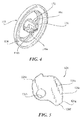
FIG. 2 is a side perspective view of the anvil assembly shown inFIG. 1 , in a second or operable position; -
FIG. 3 is an exploded prospective view of the anvil assembly shown inFIG. 2 ; -
FIG. 4 is bottom perspective view of the housing of the anvil head assembly of the anvil assembly shown inFIGS. 2 and3 ; -
FIG. 5 is a side view of a cam latch member of the anvil assembly shown inFIGS. 2 and3 ; -
FIG. 6 is a side view of the sleeve body of the sleeve assembly of the anvil assembly shown inFIGS. 2 and3 ; -
FIG. 6A is a cross-sectional view taken alongline 6A-6A shown inFIG. 6 ; -
FIG. 6B is a cross-sectional view taken alongline 6B-6B shown inFIG. 6 ; -
FIG. 6C is a cross-sectional view taken alongline 6C-6C shown inFIG. 6 ; -
FIG. 6D is a cross-sectional view taken alongline 6D-6D shown inFIG. 6 ; -
FIG. 7 is a top view of the anvil assembly shown inFIGS. 2 and3 , in the first position and including a pair of sutures received through the head assembly; -
FIG. 8 is an enlarged cross-sectional view taken along line 8-8 shown inFIG. 7 ; -
FIG. 9 is a cross-sectional view taken along line 9-9 shown inFIG. 7 ; -
FIG. 10 is an end view of the anvil assembly shown inFIGS. 2 and3 , in the operable position; -
FIG. 11 is an enlarged cross-sectional view taken along line 11-11 shown inFIG. 10 , with sleeve assembly removed; -
FIG. 12 is an enlarged cross-sectional view taken along line 12-12 shown inFIG. 10 , with sleeve assembly removed; -
FIG. 13 is a cross-sectional view of the anvil assembly shown inFIG. 2 and3 subsequent to firing of the surgical stapling device shown inFIG. 1 ; -
FIG. 14 is an alternative cross-sectional view of the anvil assembly as shown inFIG. 13 ; -
FIG. 15 is a cross-sectional view of the anvil assembly shown inFIG. 2 and3 in a second, tilted position; and, -
FIG. 16 is an alternative cross-sectional view of the anvil assembly as shown inFIG. 15 . - Embodiments of the presently disclosed anvil assembly will now be described in detail with reference to the drawings in which like reference numerals designate identical or corresponding elements in each of the several views. As is common in the art, the term "proximal" refers to that part or component closer to the user or operator, i.e. surgeon or clinician, while the term "distal" refers to that part or component further away from the user.
-
FIGS. 1-16 illustrate ananvil assembly 110 for use with a surgical stapling device 10 (FIG. 1 ) suitable for performing, for example, circular anastomoses of hollow tissue organs and hemorrohoid surgeries. Although shown as relates toanvil assembly 110 for use withsurgical stapling device 10, it is envisioned that the aspects of the present disclosure may be modified for use with any anvil assembly having an anvil head capable of being pivoted from a first tilted position, through a non-tilted operable position, to a second tilted position. It is further envisioned that the aspects of the present disclosure may also be modified for use with an anvil assembly in which the anvil head is not capable of pivoting to a first tilted position and is instead provided to a clinician in the non-tilted operable position. -
FIG. 1 illustrates an embodiment of a surgical stapling device configured for use with a tilt anvil assembly according to the present disclosure. Briefly,surgical stapling device 10 includes aproximal handle assembly 12, an elongatedcentral body portion 14 including a curved elongatedouter tube 14a, and adistal head portion 16. Alternately, in some surgical procedures, e.g., the treatment of hemorrhoids, it is desirable to have a substantially straight, shortened, central body portion. The length, shape and/or the diameter ofbody portion 14 anddistal head portion 16 may also be varied to suit a particular surgical procedure. - With reference still to
FIG. 1 , handleassembly 12 includes astationary handle 18, a firingtrigger 20, arotatable approximation knob 22, and anindicator 24. A pivotally mountedtrigger lock 26 is fastened to handleassembly 12 and is manually positioned to prevent inadvertent firing of staplingdevice 10.Indicator 24 is positioned on thestationary handle 18 and includes indicia, e.g., color coding, alpha-numeric labeling, etc., to identify to a surgeon whether the device is approximated and is ready to be fired.Head portion 16 includes ananvil assembly 110 and ashell assembly 31. A more detailed discussion ofsurgical stapler 10 is disclosed in commonly ownedU.S. Pat. Nos. 7,364,060 and7,303,106 ("the '060 Patent" and "the '106 Patent"), the contents of which are incorporated herein by reference in their entirety. - In any of the embodiments disclosed herein, the stapling
apparatus 10 can include the manually actuated handle assembly ofFIG. 1 and as described above, or can include a powered actuator assembly having drive members. For example,U.S. Patent Application No. 12/946,082, filed November 15, 2010 - Referring now to
FIGS. 2-9 , an embodiment of the anvil assembly of the present disclosure is shown generally asreference numeral 110. Referring initially toFIGS. 2-5 ,anvil assembly 110 is shown in a non-tilted or operative position wherein thestaple deforming pockets 130 face the staple slots (not shown) of surgical stapler 10 (FIG. 1 ).Anvil assembly 110 includes ahead assembly 112, acenter rod assembly 114, and asleeve member 115.Head assembly 112 includes apost 116, ahousing 118, a backup member or plate 120 (FIG. 3 ), a cutting ring 122 (FIG. 3 ), a cutting ring cover 123 (FIG. 3 ), ananvil plate 124, a spacer or washer 125(FIG. 3 ), a cam latch member 126(FIG. 5 ), and a retainer member 127 (FIG. 3 ). - With reference to
FIG. 4 , post 116 is monolithically formed with and centrally positioned withinhousing 118. Alternately,housing 118 and post 116 may be formed separately and fastened together using a known fastening technique, e.g., welding. A plurality ofteeth 116a are formed on a proximal end ofpost 116. As will be described in greater detail below,teeth 116a are configured to selectively engagesleeve member 115 during operation ofhead assembly 112. As will also be described in greater detail below, an outward facingsurface 116b ofpost 116 is configured to engagesleeve member 115 during movement ofanvil head assembly 112 from the non-tilted operational position (FIG. 14 ) to the second tilted position (FIG. 16 ). - With particular reference now to
FIG. 7 ,housing 118 includesopenings openings 119a and is used to retainhead assembly 112 in the first tilted position (as shown inFIGS. 8 and9 ) during insertion ofanvil assembly 110 within a patient. More particularly, first suture "S1" operates as a tensioning member to maintain the head assembly in the first tilted position. A second suture "S2" is inserted throughopenings 119b and is configured to permit retrieval oftilt anvil assembly 110 from within a patient if desired. During trans-oral insertion ofanvil assembly 110, second suture "S2" extends from the mouth of patient, permitting theanvil assembly 110 to be retrieved trans-orally. As shown, second suture "S2" extends in a direction opposite the direction of suture "S1". - With reference back to
FIGS. 2 and3 ,anvil plate 124 is supported in an outerannular recess 128 ofhousing 118 and includes a plurality ofstaple deforming pockets 130 for receiving and deforming staples. At least onetab 124a extends radially outwardly fromanvil plate 124 and is received within a cutout 132 (FIG. 2 ) formed in an outer rim ofhousing 118.Tab 124a andcutout 132 function to align or properly positionanvil plate 124 withinannular recess 128 ofhousing 118. - With particular reference to
FIGS. 2-4 and8 ,head assembly 112 will be described in detail.Backup plate 120 includes acentral opening 134 which is positioned aboutpost 116 within an innerannular recess 136 ofhousing 118 betweenpost 116 and outerannular recess 128.Backup plate 120 includes a raisedplatform 120a. Cuttingring 122 includes anopening 122a having a configuration substantially the same asplatform 120a. Cuttingring cover 123 is secured to an outwardly facing or proximal surface of cuttingring 122 using, for example, an adhesive. Alternately, cuttingring 122 need not have a cover. Cuttingring 122 andbackup plate 120 are slidably mounted aboutpost 116.Backup plate 120 includes a pair of inwardly extendingfingers 138 which will be described in further detail below. - With reference still to
FIGS. 2-4 and8 ,retainer member 127 is positioned in innerannular recess 136 betweenbackup plate 120 and aback wall 118a ofhousing 118. In one embodiment, and as shown,retainer member 127 is annular and includes a plurality ofdeformable tabs 127a which engage a rear surface ofbackup plate 120.Retainer member 127 preventsbackup plate 120 and cuttingring 122 from moving or being pushed into innerannular recess 136 ofhousing 118 until a predetermined force sufficient to deformtabs 127a has been applied to the backup plate/cutting ring assembly. The predetermined force can be close to, but is less than, the force applied by an annular cutting blade of a surgical stapling device when it engages, for example, the cutting ring ofanvil assembly 110. When the predetermined force is reached, e.g., during cutting of tissue,backup plate 120 is urged into innerannular recess 136 and compressesretainer member 127. It is envisioned that other crushable, deformable, collapsible or movement restricting members may be used to retain the backup plate/cutting ring assembly in a fixed position until a predetermined force has been applied to the backup plate/cutting ring assembly. - As illustrated in
FIGS. 2 ,3 , and8 , anvilcenter rod assembly 114 includes acenter rod 152, aplunger 154, andplunger spring 156. A first end ofcenter rod 152 includes a pair ofarms 159 which defines a cavity 159a. Eacharm 159 has atransverse throughbore 158 which is aligned with a central longitudinal axis ofcenter rod 152.Post 116 ofanvil head assembly 112 is dimensioned to be positioned within cavity 159a and also includes a transverse throughbore (not shown). Apivot member 162 pivotally securespost 116 tocenter rod 152 via the throughbores such thatanvil head assembly 112 may be pivotally mounted to anvilcenter rod assembly 114. - Turning briefly to
FIG. 5 ,cam latch member 126 includes abody 126a having a throughbore 126b.Throughbore 126b is dimensioned to receive pivot member 162 (FIG. 3 ) such thatcam latch member 126 is pivotally mounted within transverse slot 172 (FIG. 2 ) ofpost 116 aboutpivot member 162. - Referring now to
FIGS. 3 ,5 , and8 ,cam latch member 126 includes afirst body portion 126c which extends partially from slot 172 (FIG. 2 ) ofpost 116 and is positioned to be engaged by afinger 166 ofplunger 154.First body portion 126c is configured such that the distance between the surface offirst body portion 126c andthroughbore 126b increase in a clockwise direction aboutcam latch member 126. In this manner,plunger 154 is able to move forward ascam latch member 126 rotates in a clockwise direction. Additionally, this configuration offirst body portion 126c permits plunger 154 to be retracted ascam latch member 126 rotates in a counter-clockwise direction.Cam latch member 126 also includes anedge 126f, including atab 126g. A leading portion ofedge 126f is configured to be urged into engagement with aninner periphery 120b ofbackup plate 120 by anengagement finger 166 ofplunger 154 whenanvil head 112 is in the non-tilted operative position (FIG. 11 ).Tab 126g is configured to engagebackwall 118a ofhousing 118 to preventcam latch member 126 from rotating counter-clockwise relative tohousing 118.Tab 126g prevents the cam for over rotation once the cutring backup plate 120 is depressed. Thetab 126g contacts with the bore of 120b to prevent over rotation. - With reference to
FIGS. 3 and8 ,plunger 154 is slidably positioned in abore 164 formed in the first end ofcenter rod 152.Plunger 154 includes anengagement finger 166 which is offset a radial distance from the pivot axis ofanvil head assembly 112 and is biased into engagement withedge 126c ofcam latch 126. Engagement offinger 166 withedge 126c ofcam latch 126 presses a leading portion ofedge 126f against an inner periphery ofback plate 120 to urgeanvil head assembly 112 to the non-tilted operative position oncenter rod 152. - With reference to
FIGS. 2 and9 , a second end ofcenter rod 152 includes abore 180 defined by a plurality offlexible arms 182.Flexible arms 182 each include anopening 182a dimensioned to receive a projection formed on or connected to a shell assembly 31 (FIG. 1 ). The proximal ends of each of theflexible arms 182 include aninternal shoulder 184 dimensioned to releasably engageshell assembly 31 ofsurgical stapling device 10 to secureanvil assembly 110 to the surgical stapling device. A plurality ofsplines 186 are formed aboutcenter rod 152.Splines 186 function to alignanvil assembly 110 with the staple holding portion of a surgical stapling device. - With reference now to
FIGS. 2 ,3 , and6-6D ,sleeve member 115 includes asleeve body 190.Sleeve body 190 forms a substantially tubular member having top andbottom walls sidewalls 190c.Sleeve body 190 defines athroughbore 191 configured to be slidingly received about a distal end ofcenter rod 152.Top wall 190a defines anotch 191a and aslot 191b in a distal end ofsleeve body 190. As seen inFIG. 2 ,notch 191a is configured to permit receipt ofsleeve body 190 aboutpost 116 ofhead assembly 112. As also seen inFIG. 2 ,slot 191b is configured to accommodatefinger 166 ofplunger 154 whensleeve member 115 is in a distal-most position.Sleeve body 190 includes a plurality ofteeth 194 formed on the distal end ofbottom wall 190b and extending intothroughbore 191. As will be described in further detail below,teeth 194 ofsleeve body 190 are configured to engageteeth 116a formed onpost 116 ofhead assembly 112 to cause sliding movement ofsleeve body 190 from a first, distal-most position (FIG. 9 ), through a second, operable position (FIG. 14 ) to a third, proximal-most position (FIG. 16 ).Sleeve body 190 may optionally include an annular flange (not shown) on the outer surface of either or both of the first and second ends to facilitate retention of the anastomosis donut (not shown) aboutsleeve body 190 assleeve body 190 moves during a procedure. - With reference to
FIG. 8 ,anvil head assembly 112 may be tilted "α" degrees relative to anvilcenter rod assembly 114 to the first tilted position by first suture "S1". Titling ofanvil head assembly 112 relative to anvilcenter rod assembly 114 by first suture "S1" causescam latch member 126 positioned within the inner periphery of thebackup plate 120 to rotate, causingbody portion 126c ofcam latch member 126 to engagefinger 166 ofplunger 154. Ascam latch assembly 126 rotates counterclockwise (as viewed inFIG. 8 ) with the tilting ofanvil head assembly 112,plunger 154 is retracted withinbore 164 of anvilcenter rod assembly 114, thereby compressingspring 156. In this manner,finger 166 ofplunger 154 is distally biased againstbody portion 126c ofcam latch member 126. As can be appreciated with reference toFIGS. 9 and14 , asanvil head assembly 112 is pivoted from the non-tilted operative position (FIG. 14 ) to the first tilted position (FIG. 9 ),teeth 116a formed onpost 116 ofhousing 118 engageteeth 194 formed onsleeve body 190 ofsleeve member 115 causingsleeve body 190 to advance distally, in a direction opposite to that indicated by arrow "A" inFIG. 9 . - With reference back to
FIG. 8 , severing of suture "S1" permitsplunger 154 to extend from withinbore 164, thereby causingfinger 166 to engagebody portion 126c ofcam latch member 126. Rotation of cam latch member 126 (clockwise as viewed in the orientation ofFIG. 8 ) causesedge 126f oflatch member 126, engaged with the inner periphery ofbackup plate 120, to urgeanvil head assembly 112 to return to the non-tilted operative position (e.g. the position ofFIG. 11 ). Additionally, the distal end of stapling device 10 (FIG. 1 ) may be configured to engagefinger 166 ofplunger 154 asanvil assembly 110 is attached tosurgical stapling device 10. In this manner, the distal end ofsurgical stapling device 10 urges plunger 154 distally, thereby ensuring the rotation ofcam latch 126 andanvil head assembly 112 to the non-tilted operative position. With reference briefly toFIGS. 9 and14 , ashead assembly 112 is urged to the non-tilted position (FIG. 14 ),teeth 116a formed onpost 116 ofhead assembly 112 mesh withteeth 194 formed onsleeve body 190 ofsleeve member 115 to cause the proximal advancement ofsleeve body 190, in the direction indicated by arrow "A" (FIG. 9 ). In this manner,sleeve member 115 is positioned to receive an anastomosis donut (not shown) aboutsleeve body 190. - Referring briefly to
FIG. 12 , in the pre-fired operative position ofhead assembly 112, i.e. whenhead assembly 112 has been pivoted to the non-tilted operative position and before firing ofsurgical stapler device 10,fingers 138 formed onbackup plate 120 engageprotrusions 152b adjacenttop surface 152a ofcenter rod 152 to preventhead assembly 112 from pivoting aboutpivot member 162. - With reference back to
FIG. 1 ,anvil assembly 110 is operably received on ananvil retainer 32 extending fromshell assembly 31 formed on a distal end ofsurgical stapling device 10. Onceanvil assembly 110 is received onsurgical stapling device 10,surgical stapling device 10 operates in the manner discussed in the '060 Patent, the content of which was previously incorporated herein in its entirety. Note that alternatively, first suture "S1" (FIG. 7 ) may be severed after thedistal head portion 16 of thesurgical stapling device 10 receivesanvil assembly 110. After attachment, therotation knob 22 is rotated toapproximate anvil assembly 110 anddistal head portion 16 to clamp tissue therebetween, and then firingtrigger 20 is actuated to fire the staples (not shown) as disclosed in the '060 Patent. As seen inFIG. 2 , whenanvil head assembly 112 is in the non-tilted operative position,sleeve body 190 ofsleeve member 115 is disposed adjacent to and betweenanvil head assembly 112 and shell assembly 31 (FIG. 1 ) to receive the anastomosis donut created during the anastomosis procedure. - The operation of
anvil assembly 110 will now be described with reference toFIGS. 10-16 . Whenanvil assembly 110 is in its pre-fired non-tilted, operative position (e.g.FIGS. 11 and 12 ),backup plate 120 is spaced from backwall 118a ofhousing 118 byretainer 127 andprotrusions 152b ofcenter rod 152 engagefingers 138 ofbackup plate 120 to prevent tilting ofanvil head assembly 112 aboutpivot member 162.Finger 166 ofplunger 154 is urged byspring 156 into engagement withbody portion 126c ofcam latch member 126 to urgecam latch member 126 in a clockwise direction (as viewed inFIG. 11 ), aboutpivot member 162 such thatedge 126f ofcam latch member 126 engagesinner periphery 120b ofbackup member 120. - The firing of surgical stapling device 10 (
FIG. 1 ) causes a knife blade (not shown) to engage cuttingring 122 to move cuttingring 122 andbackup plate 120 intoannular recess 136 ofhousing 118 ofanvil head assembly 112. Arrows "W" inFIG. 13 indicate how cuttingring 122 andbackup plate 120 move as a result of the firing ofsurgical stapling device 10. When such movement occurs,deformable tabs 127a ofretainer 127 are deformed againstbackwall 118a ofhousing 118 andfingers 138 ofbackup member 120 move away fromprotrusions 152b ofcenter rod 152. Further,inner periphery 120b ofbackup plate 120 movespast edge 126f ofcam latch member 126 such thatcam latch member 126 is urged to pivot aboutpivot member 162, in the direction indicated by arrow "B" (FIG. 15 ), by plunger 154 (spring biased distally) to a position in whichbody portion 126e ofcam latch 126 is positioned in front of and engagesbackup plate 120. Engagement ofplunger 154 withcam latch member 126 urgescam member 126 to further rotate clockwise which due to its configuration enables springbiased plunger 154 to move further distally soangled surface 167 ofplunger 154 contacts a proximal surface ofpost 116 ofanvil head assembly 112 to move theanvil head assembly 118 to the third, tilted position (FIG. 16 ). It is noted thatanvil head assembly 112 will not immediately tilt to the second tilted position upon firing of surgical stapling device 10 (FIG. 1 ) because, upon firing,anvil head assembly 112 is in an approximated position, i.e., theanvil head assembly 112 is in close alignment withshell assembly 31 of staplingdevice 10, and, therefore, does not provide room forhead assembly 112 to pivot. As such, theanvil head assembly 112 will only begin to tilt whenanvil assembly 110 andshell assembly 31 ofsurgical stapling device 10 are being unapproximated and there is a sufficient gap between theanvil assembly 110 and thedistal head portion 16 of the staplingdevice 10. - As
anvil head assembly 112 pivots towards the second tilted position,finger 166 ofplunger 154 maintainssurface 126e ofcam latch member 126 in contact withbackup plate 120 to preventbackup plate 120 from sticking to the knife blade as the knife blade is retracted. It is noted thatcurved surface 126e of cam latch member is configured to eliminate any gap and ensure contact betweensurface 126e ofcam latch member 126 andbackup plate 120 to holdbackup plate 120 in place during and after the knife blade is retracted such that the cutting ring and backup plate assembly stay in their correct position during continued tilting ofanvil assembly 112. - With particular reference to
FIG. 16 , asanvil head assembly 112 pivots towards the second tilted position,teeth 116a formed onpost 116 ofanvil head assembly 112 continue to engageteeth 194 formed onsleeve body 190 ofsleeve member 115 causing continued proximal advancement ofsleeve body 190. Asanvil head assembly 112 continues to pivot,teeth 116a formed onpost 116disengage teeth 194 formed onsleeve body 190. Asteeth 116a andteeth 194 disengage, outwardly facingsurface 116b ofpost 116 engages the distal end ofbottom wall 190b ofsleeve body 190, thereby further advancingsleeve body 190 distally asanvil head assembly 112 pivots. As discussed above,sleeve member 115 is configured such that an anastomosis donut (not shown) is formed aboutsleeve body 190 during firing ofsurgical stapling device 10. In this manner, assleeve body 190 is advanced proximally by the movement ofanvil head assembly 112, the anastomosis donut is also advanced proximally. As such, the anastomosis donut is moved away fromanvil head assembly 112, thereby preventing the anastomosis donut from being pinched byanvil head assembly 112 and permitting a full range of movement ofanvil head assembly 112 relative to centerrod assembly 114. -
Anvil assembly 110 is configured such thatanvil head assembly 12 tilts to the second tilted position "β" degrees (FIG. 16 ) relative to centerrod assembly 114. As can be appreciated,anvil head assembly 112 therefore pivots in a first direction from the first, tilted position to the non-tilted operative position for application of staples. After firing of the instrument, the anvil head pivots in the same clockwise direction to the second tilted position. In one embodiment,anvil head assembly 112 is tilted less than ninety degrees and preferably about seventy degrees (70°) to its second tilted position such that the total pivoting movement of the anvil from the retracted or first tilted position to the forward or second tilted position is about one-hundred and forty degrees (140°). It should however be noted that the tilting ofanvil head assembly 112 to other degrees for the first and/or second tilted position is also contemplated.' - It will be understood that various modifications may be made to the embodiments disclosed herein. For example, the presently disclosed sleeve assemblies may be modified for use on an anvil assembly having a head assembly capable of one hundred and twenty degrees (120°) of tilt, i.e., capable of being pivoted in a counter-clockwise direction prior to firing to facilitate positioning of the anvil assembly within a lumen. Those skilled in the art will envision other modifications within the scope and spirit of the claims appended hereto.
- The invention may be described by reference to the following numbered paragraphs:-
- 1. An anvil assembly comprising:
- an anvil center rod assembly;
- a head assembly pivotally secured to the anvil center rod assembly; and
- a sleeve member slidably disposed about the anvil center rod assembly and configured to slide relative to the anvil center rod assembly as the head assembly pivots relative to the anvil center rod assembly.
- 2. The anvil assembly of paragraph 1, wherein the sleeve member includes a sleeve body disposed about the anvil center rod assembly, the sleeve body including a plurality of teeth for engaging the head assembly.
- 3. The anvil assembly of
paragraph 2, wherein the head assembly includes a housing and a post extending proximally from the housing, the post includes a plurality of teeth configured to engage the plurality of teeth formed on the sleeve body as the head assembly pivots relative to the anvil center rod assembly. - 4. The anvil assembly of paragraph 3, wherein the head assembly is configured to pivot between a first tilted position, a non-tilted operated position, and a second tilted position.
- 5. The anvil assembly of paragraph 4, wherein pivoting of the anvil assembly from the non-tilted position to the second tilted position causes the sleeve body to move proximally relative to anvil center rod assembly.
- 6. The anvil assembly of paragraph 4, wherein pivoting of the anvil assembly from the non-tilted position to the first tilted position causes the sleeve body to move distally relative to anvil center rod assembly.
- 7. The anvil assembly of paragraph 3, wherein the head assembly is tilted seventy degrees (70°) relative to the anvil center rod assembly when the head assembly is in the first tilted position.
- 8. The anvil assembly of paragraph 3, wherein the head assembly is perpendicular to the anvil center rod when the head assembly is in the non-tilted operative position.
- 9. The anvil assembly of paragraph 3, wherein the head assembly is tilted seventy degrees (70°) relative to the anvil center rod assembly when the head assembly is in the second tilted position.
- 10. The anvil assembly of paragraph 3, wherein the head assembly moves through one hundred-forty degrees (140°) when the head assembly tilts from the first tilted position, through the non-tilted position, to the second tilted position.
- 11. A surgical stapler comprising:
- a handle assembly;
- an elongated body portion extending distally from the handle assembly;
- a shell assembly secured to a distal end of the elongated body portion; and
- an anvil assembly selectively secured relative to the shell assembly, the anvil assembly including an anvil center rod assembly, a head assembly pivotally secured to the anvil center rod assembly, and a sleeve member slidably disposed about the anvil center rod assembly, the sleeve member slidable relative to the anvil center rod assembly as the head assembly pivots relative to the anvil center rod assembly.
- 12. The surgical stapler of
paragraph 11, wherein the sleeve member is disposed between the shell assembly and the head assembly during firing of the surgical stapler to receive an anastomosis donut. - 13. The surgical stapler of
paragraph 11, wherein the sleeve is member is configured to move proximally as the head assembly is moved away from the shell assembly subsequent to firing of the surgical stapler.
Claims (13)
- An anvil assembly comprising:an anvil center rod assembly;a head assembly pivotally secured to the anvil center rod assembly; anda sleeve member slidably disposed about the anvil center rod assembly and configured to slide relative to the anvil center rod assembly as the head assembly pivots relative to the anvil center rod assembly.
- The anvil assembly of claim 1, wherein the sleeve member includes a sleeve body disposed about the anvil center rod assembly, the sleeve body including a plurality of teeth for engaging the head assembly.
- The anvil assembly of claim 1 or claim 2, wherein the head assembly includes a housing and a post extending proximally from the housing, the post includes a plurality of teeth configured to engage the plurality of teeth formed on the sleeve body as the head assembly pivots relative to the anvil center rod assembly.
- The anvil assembly of claim 3, wherein the head assembly is configured to pivot between a first tilted position, a non-tilted operated position, and a second tilted position.
- The anvil assembly of claim 4, wherein pivoting of the anvil assembly from the non-tilted position to the second tilted position causes the sleeve body to move proximally relative to anvil center rod assembly.
- The anvil assembly of claim 4, wherein pivoting of the anvil assembly from the non-tilted position to the first tilted position causes the sleeve body to move distally relative to anvil center rod assembly.
- The anvil assembly of any preceding claim, wherein the head assembly is tilted seventy degrees (70°) relative to the anvil center rod assembly when the head assembly is in the first tilted position.
- The anvil assembly of any preceding claim, wherein the head assembly is perpendicular to the anvil center rod when the head assembly is in the non-tilted operative position.
- The anvil assembly of any preceding claim, wherein the head assembly is tilted seventy degrees (70°) relative to the anvil center rod assembly when the head assembly is in the second tilted position.
- The anvil assembly of claim 3, wherein the head assembly moves through one hundred-forty degrees (140°) when the head assembly tilts from the first tilted position, through the non-tilted position, to the second tilted position.
- A surgical stapler comprising:a handle assembly;an elongated body portion extending distally from the handle assembly;a shell assembly secured to a distal end of the elongated body portion; andan anvil assembly selectively secured relative to the shell assembly, the anvil assembly including an anvil center rod assembly, a head assembly pivotally secured to the anvil center rod assembly, and a sleeve member slidably disposed about the anvil center rod assembly, the sleeve member slidable relative to the anvil center rod assembly as the head assembly pivots relative to the anvil center rod assembly.
- The surgical stapler of claim 11, wherein the sleeve member is disposed between the shell assembly and the head assembly during firing of the surgical stapler to receive an anastomosis donut.
- The surgical stapler of claim 11 or claim 12, wherein the sleeve is member is configured to move proximally as the head assembly is moved away from the shell assembly subsequent to firing of the surgical stapler.
Priority Applications (1)
| Application Number | Priority Date | Filing Date | Title |
|---|---|---|---|
| EP17161304.5A EP3205292B1 (en) | 2013-06-14 | 2014-06-13 | Anvil assembly with sliding sleeve |
Applications Claiming Priority (1)
| Application Number | Priority Date | Filing Date | Title |
|---|---|---|---|
| US13/917,729 US9668740B2 (en) | 2013-06-14 | 2013-06-14 | Anvil assembly with sliding sleeve |
Related Child Applications (1)
| Application Number | Title | Priority Date | Filing Date |
|---|---|---|---|
| EP17161304.5A Division EP3205292B1 (en) | 2013-06-14 | 2014-06-13 | Anvil assembly with sliding sleeve |
Publications (3)
| Publication Number | Publication Date |
|---|---|
| EP2813188A2 true EP2813188A2 (en) | 2014-12-17 |
| EP2813188A3 EP2813188A3 (en) | 2014-12-24 |
| EP2813188B1 EP2813188B1 (en) | 2017-04-05 |
Family
ID=50972500
Family Applications (2)
| Application Number | Title | Priority Date | Filing Date |
|---|---|---|---|
| EP17161304.5A Active EP3205292B1 (en) | 2013-06-14 | 2014-06-13 | Anvil assembly with sliding sleeve |
| EP14172389.0A Active EP2813188B1 (en) | 2013-06-14 | 2014-06-13 | Anvil assembly with sliding sleeve |
Family Applications Before (1)
| Application Number | Title | Priority Date | Filing Date |
|---|---|---|---|
| EP17161304.5A Active EP3205292B1 (en) | 2013-06-14 | 2014-06-13 | Anvil assembly with sliding sleeve |
Country Status (7)
| Country | Link |
|---|---|
| US (2) | US9668740B2 (en) |
| EP (2) | EP3205292B1 (en) |
| JP (1) | JP2015000346A (en) |
| CN (1) | CN104224264B (en) |
| AU (1) | AU2014202747B2 (en) |
| CA (1) | CA2852294A1 (en) |
| ES (1) | ES2624414T3 (en) |
Cited By (2)
| Publication number | Priority date | Publication date | Assignee | Title |
|---|---|---|---|---|
| CN104490438A (en) * | 2014-12-31 | 2015-04-08 | 苏州天臣国际医疗科技有限公司 | Staple bin assembly and medical stapler using staple bin assembly |
| EP2851011A3 (en) * | 2013-09-11 | 2015-04-15 | Covidien LP | Anvil assembly with sliding sleeve |
Families Citing this family (43)
| Publication number | Priority date | Publication date | Assignee | Title |
|---|---|---|---|---|
| JP2013537056A (en) * | 2010-09-09 | 2013-09-30 | クイーン マリー アンド ウエストフィールド カレッジ、ユニバーシティ オブ ロンドン | Stoma trephine and anastomosis forming method and forming apparatus |
| US9016547B2 (en) * | 2011-10-26 | 2015-04-28 | Covidien Lp | EEA tilt top anvil with ratchet/locking mechanism |
| US9668740B2 (en) | 2013-06-14 | 2017-06-06 | Covidien Lp | Anvil assembly with sliding sleeve |
| US9554802B2 (en) * | 2013-11-13 | 2017-01-31 | Covidien Lp | Anvil assembly with frangible retaining member |
| DK3228254T3 (en) | 2014-02-21 | 2020-03-23 | 3Dintegrated Aps | KEEP INCLUDING A SURGICAL INSTRUMENT |
| US9861367B2 (en) * | 2014-06-24 | 2018-01-09 | Covidien Lp | Anvil assembly delivery systems |
| US9730694B2 (en) * | 2014-07-01 | 2017-08-15 | Covidien Lp | Loading unit including shipping assembly |
| US10426480B2 (en) * | 2015-04-29 | 2019-10-01 | Covidien Lp | Cutting ring assembly with rigid cutting member |
| US9987001B2 (en) | 2015-06-12 | 2018-06-05 | Covidien Lp | Surgical anastomosis apparatus |
| US10111668B2 (en) * | 2015-07-02 | 2018-10-30 | Covidien Lp | Anvil assembly with snap backup ring |
| US11020144B2 (en) | 2015-07-21 | 2021-06-01 | 3Dintegrated Aps | Minimally invasive surgery system |
| CN108024806B (en) | 2015-07-21 | 2022-07-01 | 3D集成公司 | Cannula assembly kit, trocar assembly kit, sleeve assembly, minimally invasive surgical system and method thereof |
| US10085756B2 (en) * | 2015-07-24 | 2018-10-02 | Covidien Lp | Anvil assembly and anvil assembly delivery system |
| DK178899B1 (en) | 2015-10-09 | 2017-05-08 | 3Dintegrated Aps | A depiction system |
| WO2017096502A1 (en) * | 2015-12-07 | 2017-06-15 | Covidien Lp | Anvil assembly and delivery system |
| GB201611306D0 (en) | 2016-06-29 | 2016-08-10 | Norwegian Univ Of Science And Tech (Ntnu) | Surgical stapler and a method of stapling tissue |
| CN110461253B (en) * | 2017-03-23 | 2023-03-10 | 柯惠有限合伙公司 | Circular suturing device with aligned splines |
| US10828026B2 (en) * | 2017-08-08 | 2020-11-10 | Covidien Lp | Tiltable anvil assembly |
| US11589871B2 (en) * | 2017-11-10 | 2023-02-28 | Cilag Gmbh International | Laparoscopic stapler with flippable housing assembly and flippable anvil assembly |
| US11006960B2 (en) * | 2018-03-28 | 2021-05-18 | Covidien Lp | Surgical anvil assemblies for surgical stapling instruments |
| US11197676B2 (en) * | 2018-06-28 | 2021-12-14 | Covidien Lp | Tie-down method for anvil assembly delivery system |
| US11141163B2 (en) * | 2018-10-04 | 2021-10-12 | Covidien Lp | Circular stapling device with anvil rotation locking structure |
| US11457921B2 (en) * | 2019-03-26 | 2022-10-04 | Covidien Lp | Anvil assembly for surgical stapling instrument |
| AU2019448247A1 (en) | 2019-05-31 | 2021-12-16 | Covidien Lp | Circular stapling device |
| US11622767B2 (en) | 2020-02-19 | 2023-04-11 | Covidien Lp | Sealed trocar assembly for stapling device |
| US11779343B2 (en) | 2020-02-26 | 2023-10-10 | Covidien Lp | Staple reload assembly with releasable knife |
| CN111407347B (en) * | 2020-03-31 | 2021-03-19 | 杭州乐守科技有限公司 | Nail anvil seat of folding anastomat |
| US11653925B2 (en) | 2020-05-21 | 2023-05-23 | Covidien Lp | Tissue relaxation monitoring for optimized tissue stapling |
| US11547405B2 (en) | 2020-05-22 | 2023-01-10 | Covidien Lp | Surgical stapling device |
| US11553921B2 (en) | 2020-07-15 | 2023-01-17 | Covidien Lp | Surgical stapling device with flexible shaft |
| US11627966B2 (en) | 2020-08-26 | 2023-04-18 | Covidien Lp | Surgical stapling device |
| US11801054B2 (en) * | 2020-09-22 | 2023-10-31 | Covidien Lp | Surgical stapler with oval tool assembly |
| US11712509B2 (en) | 2020-10-02 | 2023-08-01 | Covidien Lp | Seal assembly for circular stapling instrument |
| US11627967B2 (en) | 2020-11-23 | 2023-04-18 | Covidien Lp | Trans-anastomotic insertion device |
| US11877750B2 (en) | 2021-01-21 | 2024-01-23 | Covidien Lp | Surgical stapler with powered and manual functions |
| US11786241B2 (en) | 2021-02-16 | 2023-10-17 | Covidien Lp | Surgical stapling device including a hydraulic staple formation mechanism |
| US11553920B2 (en) | 2021-05-03 | 2023-01-17 | Covidien Lp | Trocar retainer assembly for surgical stapler |
| US11490894B1 (en) | 2021-05-12 | 2022-11-08 | Covidien Lp | Surgical device with grease filter |
| US11642131B2 (en) | 2021-05-17 | 2023-05-09 | Covidien Lp | Devices and methods for shortening a rectal stump during a lower anterior resection procedure |
| US11612400B2 (en) | 2021-05-24 | 2023-03-28 | Covidien Lp | Trocar assembly with bearing assembly for load sharing |
| US11737759B2 (en) | 2021-08-05 | 2023-08-29 | Covidien Lp | Surgical stapling device accommodating prolapsed tissue |
| US11883028B2 (en) | 2021-09-08 | 2024-01-30 | Covidien Lp | Systems and methods for post-operative anastomotic leak detection |
| US11717299B2 (en) | 2021-10-12 | 2023-08-08 | Covidien Lp | Surgical stapling device with probiotics |
Citations (3)
| Publication number | Priority date | Publication date | Assignee | Title |
|---|---|---|---|---|
| US7303106B2 (en) | 2002-10-04 | 2007-12-04 | Tyco Healthcare Group Lp | Surgical stapling device with visual indicator |
| US7364060B2 (en) | 2003-10-17 | 2008-04-29 | Tyco Healthcare Group Lp | Surgical stapling device with tiltable anvil head |
| US8109426B2 (en) | 2008-08-12 | 2012-02-07 | Tyco Healthcare Group Lp | Surgical tilt anvil assembly |
Family Cites Families (307)
| Publication number | Priority date | Publication date | Assignee | Title |
|---|---|---|---|---|
| CA908529A (en) | 1972-08-29 | V. Astafiev Georgy | Surgical instrument for suturing hollow organs in infants | |
| DE1057729B (en) | 1954-03-29 | 1959-05-21 | Lameris Instr N V | Surgical device for connecting two parts of the intestine |
| CA736256A (en) | 1962-08-27 | 1966-06-14 | S. Kasoolin Viacheslav | Instrument for suturing esophagus to intestine or stomach |
| FR1461464A (en) | 1965-08-20 | 1966-02-25 | Niiex Khirurgicheskoi Apparatu | Surgical device for suturing organs |
| CH470170A (en) | 1968-02-02 | 1969-03-31 | Vnii Khirurgicheskoi Apparatur | Device for applying round anastomoses |
| US3638652A (en) | 1970-06-01 | 1972-02-01 | James L Kelley | Surgical instrument for intraluminal anastomosis |
| US3771526A (en) | 1972-02-07 | 1973-11-13 | P Rudie | Anastomosis clamp |
| US4573468A (en) | 1977-05-26 | 1986-03-04 | United States Surgical Corporation | Hollow body organ stapling instrument and disposable cartridge employing relief vents |
| US4304236A (en) | 1977-05-26 | 1981-12-08 | United States Surgical Corporation | Stapling instrument having an anvil-carrying part of particular geometric shape |
| US4603693A (en) | 1977-05-26 | 1986-08-05 | United States Surgical Corporation | Instrument for circular surgical stapling of hollow body organs and disposable cartridge therefor |
| NL7711347A (en) | 1977-10-17 | 1979-04-19 | Carl Robert Erik Daantje | Stapling instrument for joining intestine ends - has head coupling rod in two parts screwing together with hand grip |
| US4207898A (en) | 1978-03-27 | 1980-06-17 | Senco Products, Inc. | Intralumenal anastomosis surgical stapling instrument |
| US4198982A (en) | 1978-03-31 | 1980-04-22 | Memorial Hospital For Cancer And Allied Diseases | Surgical stapling instrument and method |
| DE2947107A1 (en) | 1978-12-07 | 1980-06-26 | United States Surgical Corp | ACCURATELY ALIGNED CARTRIDGE AND INSTRUMENT FOR CLAMPING ANASTOMOSES |
| SU1088712A1 (en) | 1979-11-14 | 1984-04-30 | Всесоюзный научно-исследовательский и испытательный институт медицинской техники | Apparatus for circular suture of blood vessels |
| AU534210B2 (en) | 1980-02-05 | 1984-01-12 | United States Surgical Corporation | Surgical staples |
| US4319576A (en) | 1980-02-26 | 1982-03-16 | Senco Products, Inc. | Intralumenal anastomosis surgical stapling instrument |
| US4289133A (en) | 1980-02-28 | 1981-09-15 | Senco Products, Inc. | Cut-through backup washer for the scalpel of an intraluminal surgical stapling instrument |
| US4606343A (en) | 1980-08-18 | 1986-08-19 | United States Surgical Corporation | Self-powered surgical fastening instrument |
| US4351466A (en) | 1980-10-16 | 1982-09-28 | United States Surgical Corporation | Disposable instrument for surgical fastening |
| US4379457A (en) | 1981-02-17 | 1983-04-12 | United States Surgical Corporation | Indicator for surgical stapler |
| US4476863A (en) | 1981-03-09 | 1984-10-16 | Kanshin Nikolai N | Surgical instrument for establishing circular coloanastomoses |
| US4632290A (en) | 1981-08-17 | 1986-12-30 | United States Surgical Corporation | Surgical stapler apparatus |
| US4576167A (en) | 1981-09-03 | 1986-03-18 | United States Surgical Corporation | Surgical stapler apparatus with curved shaft |
| SU1114405A1 (en) | 1982-02-23 | 1984-09-23 | Всесоюзный научно-исследовательский и испытательный институт медицинской техники | Surgical suturing apparatus for placing compression anastomoses on the organs of digestive tract |
| US4485817A (en) | 1982-05-28 | 1984-12-04 | United States Surgical Corporation | Surgical stapler apparatus with flexible shaft |
| US4473077A (en) | 1982-05-28 | 1984-09-25 | United States Surgical Corporation | Surgical stapler apparatus with flexible shaft |
| US4488523A (en) | 1982-09-24 | 1984-12-18 | United States Surgical Corporation | Flexible, hydraulically actuated device for applying surgical fasteners |
| DE3301713A1 (en) | 1983-01-20 | 1984-07-26 | Horst Dr. 3004 Isernhagen Ziegler | Surgical clip suture apparatus for producing circular joins |
| US4592354A (en) | 1983-10-11 | 1986-06-03 | Senmed, Inc. | Tissue retention spool for intraluminal anastomotic surgical stapling instrument and methods |
| US4505414A (en) | 1983-10-12 | 1985-03-19 | Filipi Charles J | Expandable anvil surgical stapler |
| US4550870A (en) | 1983-10-13 | 1985-11-05 | Alchemia Ltd. Partnership | Stapling device |
| IT1173284B (en) | 1984-02-16 | 1987-06-18 | Riccardo Rosati | CIRCULAR MECHANICAL STAPLING MACHINE |
| US4667673A (en) | 1984-03-12 | 1987-05-26 | American Cyanamid Company | Anastomotic device applicator and method |
| US4754909A (en) | 1984-08-09 | 1988-07-05 | Barker John M | Flexible stapler |
| US4671445A (en) | 1984-08-09 | 1987-06-09 | Baxter Travenol Laboratories, Inc. | Flexible surgical stapler assembly |
| AU582625B2 (en) | 1985-01-28 | 1989-04-06 | Ethicon Inc. | Tissue gripper for use with intraluminal stapling device |
| US4665917A (en) | 1985-01-28 | 1987-05-19 | Ethicon, Inc. | Tissue gripper for use with intraluminal stapling device |
| US4703887A (en) | 1985-01-28 | 1987-11-03 | Ethicon, Inc. | Collapsible purse string aid for use with intraluminal stapling device |
| JPS635697Y2 (en) | 1985-04-04 | 1988-02-17 | ||
| JPS62140776A (en) | 1985-12-16 | 1987-06-24 | 海老原 代師行 | Stapler |
| US4903697A (en) | 1986-03-27 | 1990-02-27 | Semion Resnick | Cartridge assembly for a surgical stapling instrument |
| US4700703A (en) | 1986-03-27 | 1987-10-20 | Semion Resnick | Cartridge assembly for a surgical stapling instrument |
| AU7286587A (en) | 1986-04-21 | 1987-11-24 | Globe Control Finanzaktiengesellschaft | Anastomosis process and device |
| US4752024A (en) | 1986-10-17 | 1988-06-21 | Green David T | Surgical fastener and surgical stapling apparatus |
| US4917114A (en) | 1986-10-17 | 1990-04-17 | United States Surgical Corporation | Surgical fastener and surgical stapling apparatus |
| US4893622A (en) | 1986-10-17 | 1990-01-16 | United States Surgical Corporation | Method of stapling tubular body organs |
| US4776506A (en) | 1986-11-13 | 1988-10-11 | United States Surgical Corporation | Surgical stapler apparatus |
| US4873977A (en) | 1987-02-11 | 1989-10-17 | Odis L. Avant | Stapling method and apparatus for vesicle-urethral re-anastomosis following retropubic prostatectomy and other tubular anastomosis |
| US5119983A (en) | 1987-05-26 | 1992-06-09 | United States Surgical Corporation | Surgical stapler apparatus |
| US5285944A (en) | 1987-05-26 | 1994-02-15 | United States Surgical Corporation | Surgical stapler apparatus |
| US5158222A (en) | 1987-05-26 | 1992-10-27 | United States Surgical Corp. | Surgical stapler apparatus |
| SU1616624A1 (en) | 1987-07-14 | 1990-12-30 | Предприятие П/Я А-3697 | Surgical suturing apparatus |
| SU1509052A1 (en) | 1988-01-18 | 1989-09-23 | С. А. Попов | Surgical suturing apparatus |
| US4907591A (en) | 1988-03-29 | 1990-03-13 | Pfizer Hospital Products Group, Inc. | Surgical instrument for establishing compression anastomosis |
| US5193731A (en) | 1988-07-01 | 1993-03-16 | United States Surgical Corporation | Anastomosis surgical stapling instrument |
| US5005749A (en) | 1988-07-01 | 1991-04-09 | United States Surgical Corp. | Anastomosis surgical stapling instrument |
| ES2011110A6 (en) | 1988-09-02 | 1989-12-16 | Lopez Hervas Pedro | Hydraulic device with flexible body for surgical anastomosts |
| US5197648A (en) | 1988-11-29 | 1993-03-30 | Gingold Bruce S | Surgical stapling apparatus |
| AU4742190A (en) | 1988-11-29 | 1990-06-26 | Bruce S. Gingold | Surgical stapling apparatus |
| CH677728A5 (en) | 1989-10-17 | 1991-06-28 | Bieffe Medital Sa | |
| US5403333A (en) | 1990-08-28 | 1995-04-04 | Robert L. Kaster | Side-to-end vascular anastomotic staple apparatus |
| US5047039A (en) | 1990-09-14 | 1991-09-10 | Odis Lynn Avant | Method and apparatus for effecting dorsal vein ligation and tubular anastomosis and laparoscopic prostatectomy |
| US5253793A (en) | 1990-09-17 | 1993-10-19 | United States Surgical Corporation | Apparatus for applying two-part surgical fasteners |
| US5104025A (en) | 1990-09-28 | 1992-04-14 | Ethicon, Inc. | Intraluminal anastomotic surgical stapler with detached anvil |
| US5042707A (en) | 1990-10-16 | 1991-08-27 | Taheri Syde A | Intravascular stapler, and method of operating same |
| CA2055943C (en) | 1990-12-06 | 2003-09-23 | Daniel P. Rodak | Surgical fastening apparatus with locking mechanism |
| US5122156A (en) | 1990-12-14 | 1992-06-16 | United States Surgical Corporation | Apparatus for securement and attachment of body organs |
| US5222963A (en) | 1991-01-17 | 1993-06-29 | Ethicon, Inc. | Pull-through circular anastomosic intraluminal stapler with absorbable fastener means |
| EP0533897B1 (en) | 1991-03-29 | 1996-03-13 | Laboratoire Perouse Implant | Surgical stapler |
| US5221036A (en) | 1991-06-11 | 1993-06-22 | Haruo Takase | Surgical stapler |
| US5333773A (en) | 1991-08-23 | 1994-08-02 | Ethicon, Inc. | Sealing means for endoscopic surgical anastomosis stapling instrument |
| US5350104A (en) | 1991-08-23 | 1994-09-27 | Ethicon, Inc. | Sealing means for endoscopic surgical anastomosis stapling instrument |
| GR920100358A (en) | 1991-08-23 | 1993-06-07 | Ethicon Inc | Surgical anastomosis stapling instrument. |
| US5474223A (en) | 1991-10-18 | 1995-12-12 | United States Surgical Corporation | Surgical fastener applying apparatus |
| US5443198A (en) | 1991-10-18 | 1995-08-22 | United States Surgical Corporation | Surgical fastener applying apparatus |
| US5197649A (en) | 1991-10-29 | 1993-03-30 | The Trustees Of Columbia University In The City Of New York | Gastrointestinal endoscoptic stapler |
| US5433721A (en) | 1992-01-17 | 1995-07-18 | Ethicon, Inc. | Endoscopic instrument having a torsionally stiff drive shaft for applying fasteners to tissue |
| US5188638A (en) | 1992-02-06 | 1993-02-23 | Tzakis Andreas G | Apparatus and method for preforming anastomosis fastener securement of hollow organs |
| US5271543A (en) | 1992-02-07 | 1993-12-21 | Ethicon, Inc. | Surgical anastomosis stapling instrument with flexible support shaft and anvil adjusting mechanism |
| US5348259A (en) | 1992-02-10 | 1994-09-20 | Massachusetts Institute Of Technology | Flexible, articulable column |
| US5282810A (en) | 1992-04-08 | 1994-02-01 | American Cyanamid Company | Surgical anastomosis device |
| US5425738A (en) | 1992-04-08 | 1995-06-20 | American Cyanamid Company | Endoscopic anastomosis ring insertion device and method of use thereof |
| US5355897A (en) | 1992-04-16 | 1994-10-18 | Ethicon, Inc. | Method of performing a pyloroplasty/pylorectomy using a stapler having a shield |
| US5314435A (en) | 1992-05-19 | 1994-05-24 | United States Surgical Corporation | Anvil delivery system |
| US5344059A (en) | 1992-05-19 | 1994-09-06 | United States Surgical Corporation | Surgical apparatus and anvil delivery system therefor |
| US5658300A (en) | 1992-06-04 | 1997-08-19 | Olympus Optical Co., Ltd. | Tissue fixing surgical instrument, tissue-fixing device, and method of fixing tissues |
| JPH0647050A (en) | 1992-06-04 | 1994-02-22 | Olympus Optical Co Ltd | Tissue suture and ligature device |
| US5360154A (en) | 1992-07-17 | 1994-11-01 | United States Surgical Corporation | Apparatus for creating partial anastomoses |
| US5330486A (en) | 1992-07-29 | 1994-07-19 | Wilk Peter J | Laparoscopic or endoscopic anastomosis technique and associated instruments |
| US5261920A (en) | 1992-08-21 | 1993-11-16 | Ethicon, Inc. | Anvil bushing for circular stapler |
| US5368215A (en) | 1992-09-08 | 1994-11-29 | United States Surgical Corporation | Surgical apparatus and detachable anvil rod therefor |
| US5381943A (en) * | 1992-10-09 | 1995-01-17 | Ethicon, Inc. | Endoscopic surgical stapling instrument with pivotable and rotatable staple cartridge |
| US5309927A (en) | 1992-10-22 | 1994-05-10 | Ethicon, Inc. | Circular stapler tissue retention spring method |
| US5314436A (en) | 1992-10-30 | 1994-05-24 | Wilk Peter J | Method and apparatus for performing end-to-end anastomoses |
| US5404870A (en) | 1993-05-28 | 1995-04-11 | Ethicon, Inc. | Method of using a transanal inserter |
| US5503320A (en) | 1993-08-19 | 1996-04-02 | United States Surgical Corporation | Surgical apparatus with indicator |
| US5454825A (en) | 1993-10-01 | 1995-10-03 | United States Surgical Corporation | Circular anastomosis device with seal |
| US5447514A (en) | 1993-10-01 | 1995-09-05 | United States Surgical Corporation | Circular anastomosis device |
| US5437684A (en) | 1993-10-01 | 1995-08-01 | United States Surgical Corporation | Circular anastomosis device |
| US5522534A (en) | 1993-10-01 | 1996-06-04 | United States Surgical Corporation | Anvil for surgical stapler |
| CA2132917C (en) | 1993-10-07 | 2004-12-14 | John Charles Robertson | Circular anastomosis device |
| US5503635A (en) | 1993-11-12 | 1996-04-02 | United States Surgical Corporation | Apparatus and method for performing compressional anastomoses |
| DE4407668A1 (en) | 1994-03-09 | 1995-09-14 | Ferdinand Dr Koeckerling | Surgical anastomotic ring setting device |
| US5464415A (en) | 1994-03-15 | 1995-11-07 | Chen; Te-Chuan | Sutureless intestinal anastomosis gun |
| US5860581A (en) | 1994-03-24 | 1999-01-19 | United States Surgical Corporation | Anvil for circular stapler |
| US5715987A (en) | 1994-04-05 | 1998-02-10 | Tracor Incorporated | Constant width, adjustable grip, staple apparatus and method |
| CA2147800C (en) | 1994-05-26 | 2006-07-11 | John Charles Robertson | Circular anastomosis device |
| US5881943A (en) | 1994-06-17 | 1999-03-16 | Heartport, Inc. | Surgical anastomosis apparatus and method thereof |
| US5732872A (en) | 1994-06-17 | 1998-03-31 | Heartport, Inc. | Surgical stapling instrument |
| CA2192819A1 (en) | 1994-06-17 | 1995-12-28 | Christopher Francis Heck | Surgical stapling instrument and method thereof |
| CA2146508C (en) | 1994-08-25 | 2006-11-14 | Robert H. Schnut | Anvil for circular stapler |
| US5685474A (en) | 1994-10-04 | 1997-11-11 | United States Surgical Corporation | Tactile indicator for surgical instrument |
| US5868760A (en) | 1994-12-07 | 1999-02-09 | Mcguckin, Jr.; James F. | Method and apparatus for endolumenally resectioning tissue |
| US7235089B1 (en) | 1994-12-07 | 2007-06-26 | Boston Scientific Corporation | Surgical apparatus and method |
| US5720755A (en) | 1995-01-18 | 1998-02-24 | Dakov; Pepi | Tubular suturing device and methods of use |
| US5904697A (en) | 1995-02-24 | 1999-05-18 | Heartport, Inc. | Devices and methods for performing a vascular anastomosis |
| DE19509115C2 (en) | 1995-03-16 | 1997-11-27 | Deutsche Forsch Luft Raumfahrt | Surgical device for preparing an anastomosis using minimally invasive surgical techniques |
| US5769841A (en) | 1995-06-13 | 1998-06-23 | Electroscope, Inc. | Electrosurgical apparatus for laparoscopic and like procedures |
| US5641111A (en) | 1995-06-28 | 1997-06-24 | Ethicon Endo-Surgery, Inc. | Surgical stapling instrument with anvil cutting guide |
| US5749896A (en) | 1995-07-18 | 1998-05-12 | Cook; Melvin S. | Staple overlap |
| US5839639A (en) | 1995-08-17 | 1998-11-24 | Lasersurge, Inc. | Collapsible anvil assembly and applicator instrument |
| US5814055A (en) | 1995-09-19 | 1998-09-29 | Ethicon Endo-Surgery, Inc. | Surgical clamping mechanism |
| WO1997016122A1 (en) | 1995-10-31 | 1997-05-09 | Oticon A/S | Method and anastomotic instrument for use when performing an end-to-side anastomosis |
| US5836503A (en) | 1996-04-22 | 1998-11-17 | United States Surgical Corporation | Insertion device for surgical apparatus |
| US6050472A (en) | 1996-04-26 | 2000-04-18 | Olympus Optical Co., Ltd. | Surgical anastomosis stapler |
| US6119913A (en) | 1996-06-14 | 2000-09-19 | Boston Scientific Corporation | Endoscopic stapler |
| US5833698A (en) | 1996-07-23 | 1998-11-10 | United States Surgical Corporation | Anastomosis instrument and method |
| US6440146B2 (en) | 1996-07-23 | 2002-08-27 | United States Surgical Corporation | Anastomosis instrument and method |
| US20020019642A1 (en) | 1996-07-23 | 2002-02-14 | Keith Milliman | Anastomosis instrument and method for performing same |
| US6024748A (en) | 1996-07-23 | 2000-02-15 | United States Surgical Corporation | Singleshot anastomosis instrument with detachable loading unit and method |
| US5855312A (en) | 1996-07-25 | 1999-01-05 | Toledano; Haviv | Flexible annular stapler for closed surgery of hollow organs |
| US6338737B1 (en) | 1997-07-17 | 2002-01-15 | Haviv Toledano | Flexible annular stapler for closed surgery of hollow organs |
| US5865361A (en) | 1997-09-23 | 1999-02-02 | United States Surgical Corporation | Surgical stapling apparatus |
| US6117148A (en) | 1997-10-17 | 2000-09-12 | Ravo; Biagio | Intraluminal anastomotic device |
| US5951576A (en) | 1998-03-02 | 1999-09-14 | Wakabayashi; Akio | End-to-side vascular anastomosing stapling device |
| US6279809B1 (en) | 1998-03-10 | 2001-08-28 | Enrico Nicolo | Circular stapler for side to end, side to side and end to side anastomosis |
| EP1077647A2 (en) | 1998-05-11 | 2001-02-28 | Claire T. Hovland | Devices and methods for treating e.g. urinary stress incontinence |
| US6517566B1 (en) | 1998-05-11 | 2003-02-11 | Surgical Connections, Inc. | Devices and methods for treating e.g. urinary stress incontinence |
| US6601749B2 (en) | 1998-06-19 | 2003-08-05 | Scimed Life Systems, Inc. | Multi fire full thickness resectioning device |
| US6629630B2 (en) | 1998-06-19 | 2003-10-07 | Scimed Life Systems, Inc. | Non-circular resection device and endoscope |
| US6478210B2 (en) | 2000-10-25 | 2002-11-12 | Scimed Life Systems, Inc. | Method and device for full thickness resectioning of an organ |
| US6585144B2 (en) | 1998-06-19 | 2003-07-01 | Acimed Life Systems, Inc. | Integrated surgical staple retainer for a full thickness resectioning device |
| US6126058A (en) | 1998-06-19 | 2000-10-03 | Scimed Life Systems, Inc. | Method and device for full thickness resectioning of an organ |
| DE19836950B4 (en) | 1998-08-17 | 2004-09-02 | Deutsches Zentrum für Luft- und Raumfahrt e.V. | Surgical instrument in the form of a suturing device |
| DE19837258A1 (en) | 1998-08-17 | 2000-03-02 | Deutsch Zentr Luft & Raumfahrt | Device for operating a surgical instrument for anastomosis of hollow organs |
| US6203553B1 (en) | 1999-09-08 | 2001-03-20 | United States Surgical | Stapling apparatus and method for heart valve replacement |
| US6142933A (en) | 1998-11-23 | 2000-11-07 | Ethicon Endo-Surgery, Inc. | Anoscope for hemorrhoidal surgery |
| US6083241A (en) | 1998-11-23 | 2000-07-04 | Ethicon Endo-Surgery, Inc. | Method of use of a circular stapler for hemorrhoidal procedure |
| US6102271A (en) | 1998-11-23 | 2000-08-15 | Ethicon Endo-Surgery, Inc. | Circular stapler for hemorrhoidal surgery |
| US6626921B2 (en) | 1999-04-16 | 2003-09-30 | Integrated Vascular Interventional Technologies, L.C. | Externally positioned anvil apparatus for cutting anastomosis |
| US6652542B2 (en) | 1999-04-16 | 2003-11-25 | Integrated Vascular Interventional Technologies, L.C. (Ivit, Lc) | External anastomosis operators and related systems for anastomosis |
| US6551334B2 (en) | 1999-04-16 | 2003-04-22 | Integrated Vascular Interventional Technologies, Lc | Externally directed anastomosis systems and externally positioned anastomosis fenestra cutting apparatus |
| US6743244B2 (en) | 1999-04-16 | 2004-06-01 | Integrated Vascular Interventional Technologies, L.C. | Soft anvil apparatus for cutting anastomosis fenestra |
| US6402008B1 (en) | 1999-04-19 | 2002-06-11 | Deborah A. Lucas | Surgical stapler assembly with interchangeable heads |
| US6068636A (en) | 1999-04-23 | 2000-05-30 | Chen; Te-Chuan | Intra-intestinal bypass gun |
| US6716233B1 (en) | 1999-06-02 | 2004-04-06 | Power Medical Interventions, Inc. | Electromechanical driver and remote surgical instrument attachment having computer assisted control capabilities |
| US6443973B1 (en) | 1999-06-02 | 2002-09-03 | Power Medical Interventions, Inc. | Electromechanical driver device for use with anastomosing, stapling, and resecting instruments |
| US7032798B2 (en) | 1999-06-02 | 2006-04-25 | Power Medical Interventions, Inc. | Electro-mechanical surgical device |
| US8025199B2 (en) | 2004-02-23 | 2011-09-27 | Tyco Healthcare Group Lp | Surgical cutting and stapling device |
| US6793652B1 (en) | 1999-06-02 | 2004-09-21 | Power Medical Interventions, Inc. | Electro-mechanical surgical device |
| US6315184B1 (en) | 1999-06-02 | 2001-11-13 | Powermed, Inc. | Stapling device for use with an electromechanical driver device for use with anastomosing, stapling, and resecting instruments |
| US6264087B1 (en) | 1999-07-12 | 2001-07-24 | Powermed, Inc. | Expanding parallel jaw device for use with an electromechanical driver device |
| US6491201B1 (en) | 2000-02-22 | 2002-12-10 | Power Medical Interventions, Inc. | Fluid delivery mechanism for use with anastomosing, stapling, and resecting instruments |
| US6981941B2 (en) | 1999-06-02 | 2006-01-03 | Power Medical Interventions | Electro-mechanical surgical device |
| EP1251786B1 (en) | 2000-01-18 | 2007-03-14 | Tyco Healthcare Group Lp | Anastomosis instrument |
| US6193129B1 (en) | 2000-01-24 | 2001-02-27 | Ethicon Endo-Surgery, Inc. | Cutting blade for a surgical anastomosis stapling instrument |
| HU225908B1 (en) | 2000-01-24 | 2007-12-28 | Ethicon Endo Surgery Europe | Surgical circular stapling head |
| US6533157B1 (en) | 2000-02-22 | 2003-03-18 | Power Medical Interventions, Inc. | Tissue stapling attachment for use with an electromechanical driver device |
| US6488197B1 (en) | 2000-02-22 | 2002-12-03 | Power Medical Interventions, Inc. | Fluid delivery device for use with anastomosing resecting and stapling instruments |
| US6273897B1 (en) | 2000-02-29 | 2001-08-14 | Ethicon, Inc. | Surgical bettress and surgical stapling apparatus |
| ES2316441T3 (en) | 2000-03-06 | 2009-04-16 | Tyco Healthcare Group Lp | APPARATUS TO PERFORM A PROCEDURE OF BAIPAS IN A DIGESTIVE SYSTEM. |
| IL139788A (en) | 2000-11-20 | 2006-10-05 | Minelu Zonnenschein | Stapler for endoscopes |
| US6592596B1 (en) | 2000-05-10 | 2003-07-15 | Scimed Life Systems, Inc. | Devices and related methods for securing a tissue fold |
| US20040267310A1 (en) | 2000-10-20 | 2004-12-30 | Racenet David C | Directionally biased staple and anvil assembly for forming the staple |
| US6821282B2 (en) | 2000-11-27 | 2004-11-23 | Scimed Life Systems, Inc. | Full thickness resection device control handle |
| US8286845B2 (en) | 2000-11-27 | 2012-10-16 | Boston Scientific Scimed, Inc. | Full thickness resection device control handle |
| US6398795B1 (en) | 2000-11-30 | 2002-06-04 | Scimed Life Systems, Inc. | Stapling and cutting in resectioning for full thickness resection devices |
| US6439446B1 (en) | 2000-12-01 | 2002-08-27 | Stephen J. Perry | Safety lockout for actuator shaft |
| US6503259B2 (en) | 2000-12-27 | 2003-01-07 | Ethicon, Inc. | Expandable anastomotic device |
| US6632237B2 (en) | 2001-01-11 | 2003-10-14 | Bio-Seal Tech, Inc. | Device and method for sealing a puncture in a blood vessel |
| CA2435209C (en) | 2001-01-24 | 2009-08-25 | Tyco Healthcare Group Lp | Anastomosis instrument and method for performing same |
| EP1359851B1 (en) | 2001-01-31 | 2010-09-22 | Rex Medical, Inc. | Apparatus for stapling and resectioning gastro-edophageal tissue |
| US6769590B2 (en) | 2001-04-02 | 2004-08-03 | Susan E. Vresh | Luminal anastomotic device and method |
| EP2397080B1 (en) | 2001-04-03 | 2018-08-01 | Covidien LP | Surgical stapling device |
| US6632227B2 (en) | 2001-08-24 | 2003-10-14 | Scimed Life Systems, Inc. | Endoscopic resection devices |
| US20050107813A1 (en) | 2001-09-17 | 2005-05-19 | Vincente Gilete Garcia | Bone fixing device for cranial surgery |
| US6578751B2 (en) | 2001-09-26 | 2003-06-17 | Scimed Life Systems, Inc. | Method of sequentially firing staples using springs and a rotary or linear shutter |
| US20070060952A1 (en) | 2005-09-02 | 2007-03-15 | Roby Mark S | Surgical stapling device with coated knife blade |
| US6605098B2 (en) | 2001-09-28 | 2003-08-12 | Ethicon, Inc. | Surgical device for creating an anastomosis between first and second hollow organs |
| EP1437970B1 (en) | 2001-10-05 | 2010-12-08 | Tyco Healthcare Group LP | Tilt top anvil for a surgical fastener device |
| US6605078B2 (en) | 2001-11-26 | 2003-08-12 | Scimed Life Systems, Inc. | Full thickness resection device |
| DE10158246C1 (en) | 2001-11-28 | 2003-08-21 | Ethicon Endo Surgery Europe | Surgical stapling instrument |
| US6981979B2 (en) | 2001-12-14 | 2006-01-03 | Enrico Nicolo | Surgical anastomotic devices |
| US20030111507A1 (en) | 2001-12-14 | 2003-06-19 | George Nunez | Balloon actuator for use in a resectioning device |
| US6905504B1 (en) | 2002-02-26 | 2005-06-14 | Cardica, Inc. | Tool for performing end-to-end anastomosis |
| US7128748B2 (en) | 2002-03-26 | 2006-10-31 | Synovis Life Technologies, Inc. | Circular stapler buttress combination |
| AU2003234239A1 (en) | 2002-04-24 | 2003-11-10 | Surgical Connections, Inc. | Resection and anastomosis devices and methods |
| WO2003090630A2 (en) | 2002-04-25 | 2003-11-06 | Tyco Healthcare Group, Lp | Surgical instruments including micro-electromechanical systems (mems) |
| US6685079B2 (en) | 2002-05-24 | 2004-02-03 | Scimed Life Systems, Inc. | Full thickness resectioning device |
| US6769594B2 (en) | 2002-05-31 | 2004-08-03 | Tyco Healthcare Group, Lp | End-to-end anastomosis instrument and method for performing same |
| US7195142B2 (en) | 2003-05-30 | 2007-03-27 | Tyco Healthcare Group Lp | End-to-end anastomosis instrument and method for performing same |
| EP1515645B1 (en) | 2002-06-17 | 2006-08-16 | Tyco Healthcare Group Lp | Annular support structures |
| IL150855A (en) | 2002-07-22 | 2007-06-03 | Leonid Monassevitch | Intratubular anastomosis apparatus |
| WO2004032760A2 (en) | 2002-10-04 | 2004-04-22 | Tyco Healthcare Group, Lp | Pneumatic powered surgical stapling device |
| US7220237B2 (en) | 2002-10-23 | 2007-05-22 | Satiety, Inc. | Method and device for use in endoscopic organ procedures |
| WO2004058078A1 (en) | 2002-12-16 | 2004-07-15 | Edrich Vascular Devices, Inc. | Multiple stapling device for narrow blood vessels |
| WO2004058080A2 (en) | 2002-12-20 | 2004-07-15 | Tyco Healthcare Group, Lp | Vacuum assisted surgical stapler |
| US6852122B2 (en) | 2003-01-23 | 2005-02-08 | Cordis Corporation | Coated endovascular AAA device |
| KR100547166B1 (en) | 2003-04-11 | 2006-01-26 | 허윤석 | Improved circular stapler |
| EP2633822B1 (en) | 2003-06-20 | 2015-09-23 | Covidien LP | Surgical stapling device |
| EP2620104A3 (en) | 2003-07-16 | 2014-05-14 | Covidien LP | Surgical stapling device with tissue tensioner |
| US7686201B2 (en) | 2003-09-01 | 2010-03-30 | Tyco Healthcare Group Lp | Circular stapler for hemorrhoid operations |
| US7547312B2 (en) | 2003-09-17 | 2009-06-16 | Gore Enterprise Holdings, Inc. | Circular stapler buttress |
| US7309341B2 (en) | 2003-09-30 | 2007-12-18 | Ethicon Endo-Surgery, Inc. | Single lumen anastomosis applier for self-deploying fastener |
| US8590764B2 (en) | 2003-12-24 | 2013-11-26 | Boston Scientific Scimed, Inc. | Circumferential full thickness resectioning device |
| US7585306B2 (en) | 2003-12-24 | 2009-09-08 | Maquet Cardiovascular Llc | Anastomosis device, tools and methods of using |
| US6953138B1 (en) | 2004-02-18 | 2005-10-11 | Frank W. Dworak | Surgical stapler anvil with nested staple forming pockets |
| US7086267B2 (en) | 2004-02-18 | 2006-08-08 | Frank W. Dworak | Metal-forming die and method for manufacturing same |
| US7118528B1 (en) | 2004-03-16 | 2006-10-10 | Gregory Piskun | Hemorrhoids treatment method and associated instrument assembly including anoscope and cofunctioning tissue occlusion device |
| US8181840B2 (en) | 2004-03-19 | 2012-05-22 | Tyco Healthcare Group Lp | Tissue tensioner assembly and approximation mechanism for surgical stapling device |
| ES2400050T3 (en) * | 2004-03-19 | 2013-04-05 | Covidien Lp | Anvil set with improved cutting ring |
| US7585307B2 (en) | 2004-05-17 | 2009-09-08 | Edrich Health Technologies, Inc. | Surgical stapling system |
| JP4257270B2 (en) | 2004-07-14 | 2009-04-22 | オリンパス株式会社 | Biological tissue suturing method and biological tissue suturing device |
| US8317074B2 (en) | 2004-07-28 | 2012-11-27 | Ethicon Endo-Surgery, Inc. | Electroactive polymer-based articulation mechanism for circular stapler |
| US7182239B1 (en) | 2004-08-27 | 2007-02-27 | Myers Stephan R | Segmented introducer device for a circular surgical stapler |
| KR100646762B1 (en) | 2004-09-10 | 2006-11-23 | 인하대학교 산학협력단 | A staple for operation and a stapler for operation provided with the same |
| EP1804682B1 (en) | 2004-10-18 | 2017-11-29 | Covidien LP | Structure for applying sprayable wound treatment material |
| US7717313B2 (en) | 2004-10-18 | 2010-05-18 | Tyco Healthcare Group Lp | Surgical apparatus and structure for applying sprayable wound treatment material |
| ES2389208T3 (en) | 2004-10-18 | 2012-10-24 | Tyco Healthcare Group Lp | Annular adhesive structure |
| CA2583867C (en) | 2004-10-18 | 2014-12-23 | Frank J. Viola | Adhesive suture structure and methods of using the same |
| US7455682B2 (en) | 2004-10-18 | 2008-11-25 | Tyco Healthcare Group Lp | Structure containing wound treatment material |
| US7845536B2 (en) | 2004-10-18 | 2010-12-07 | Tyco Healthcare Group Lp | Annular adhesive structure |
| WO2006044194A2 (en) | 2004-10-18 | 2006-04-27 | Tyco Healthcare Group, Lp | Compression anastomosis device and method |
| US7938307B2 (en) | 2004-10-18 | 2011-05-10 | Tyco Healthcare Group Lp | Support structures and methods of using the same |
| ITMI20042132A1 (en) | 2004-11-05 | 2005-02-05 | Ethicon Endo Surgery Inc | DEVICE AND METHOD FOR OBESITY THERAPY |
| US7207168B2 (en) | 2004-11-19 | 2007-04-24 | The Schnipke Family Limited Liability Company | Apparatus and method for inserting staple drivers in a cartridge |
| WO2006079260A1 (en) | 2005-01-26 | 2006-08-03 | Suzhou Touchstone International Medical Science Co., Ltd | A rotatable cutter head of a surgical stapler |
| US20060201989A1 (en) | 2005-03-11 | 2006-09-14 | Ojeda Herminio F | Surgical anvil and system for deploying the same |
| US9364229B2 (en) | 2005-03-15 | 2016-06-14 | Covidien Lp | Circular anastomosis structures |
| US7717312B2 (en) | 2005-06-03 | 2010-05-18 | Tyco Healthcare Group Lp | Surgical instruments employing sensors |
| US8028885B2 (en) | 2006-05-19 | 2011-10-04 | Ethicon Endo-Surgery, Inc. | Electric surgical instrument with optimized power supply and drive |
| US8627995B2 (en) | 2006-05-19 | 2014-01-14 | Ethicon Endo-Sugery, Inc. | Electrically self-powered surgical instrument with cryptographic identification of interchangeable part |
| US7959050B2 (en) | 2005-07-26 | 2011-06-14 | Ethicon Endo-Surgery, Inc | Electrically self-powered surgical instrument with manual release |
| US20070029363A1 (en) | 2005-08-07 | 2007-02-08 | Sergey Popov | Surgical apparatus with remote drive |
| US7398908B2 (en) | 2005-08-15 | 2008-07-15 | Tyco Healthcare Group Lp | Surgical stapling instruments including a cartridge having multiple staple sizes |
| US7401721B2 (en) | 2005-08-15 | 2008-07-22 | Tyco Healthcare Group Lp | Surgical stapling instruments including a cartridge having multiple staple sizes |
| US7407075B2 (en) | 2005-08-15 | 2008-08-05 | Tyco Healthcare Group Lp | Staple cartridge having multiple staple sizes for a surgical stapling instrument |
| US7771440B2 (en) | 2005-08-18 | 2010-08-10 | Ethicon Endo-Surgery, Inc. | Method and apparatus for endoscopically performing gastric reduction surgery in a single pass |
| US7673781B2 (en) | 2005-08-31 | 2010-03-09 | Ethicon Endo-Surgery, Inc. | Surgical stapling device with staple driver that supports multiple wire diameter staples |
| CN2868208Y (en) | 2005-12-14 | 2007-02-14 | 苏州天臣国际医疗科技有限公司 | Tubular binding instrument having automatic safety unit |
| US7422138B2 (en) | 2006-02-01 | 2008-09-09 | Ethicon Endo-Surgery, Inc. | Elliptical intraluminal surgical stapler for anastomosis |
| US7793813B2 (en) | 2006-02-28 | 2010-09-14 | Tyco Healthcare Group Lp | Hub for positioning annular structure on a surgical device |
| US20100019016A1 (en) | 2006-03-23 | 2010-01-28 | Edoga John K | Vascular Anastomotic Staplers |
| US8540132B2 (en) * | 2006-05-16 | 2013-09-24 | Covidien Lp | Tilt anvil assembly |
| EP1875870B1 (en) | 2006-07-07 | 2009-12-02 | Ethicon Endo-Surgery, Inc. | A surgical stapling instrument. |
| US8205782B2 (en) | 2006-07-12 | 2012-06-26 | Niti Surgical Solutions Ltd. | Compression assemblies and applicators for use therewith |
| US7527185B2 (en) | 2006-07-12 | 2009-05-05 | Niti Surgical Solutions Ltd. | Compression anastomosis ring assembly and applicator for use therewith |
| US8348131B2 (en) | 2006-09-29 | 2013-01-08 | Ethicon Endo-Surgery, Inc. | Surgical stapling instrument with mechanical indicator to show levels of tissue compression |
| AU2007348492B9 (en) | 2007-03-07 | 2013-04-18 | Covidien Ag | Stapler for mucosectomy |
| US7438209B1 (en) | 2007-03-15 | 2008-10-21 | Ethicon Endo-Surgery, Inc. | Surgical stapling instruments having a releasable staple-forming pocket |
| US8038045B2 (en) | 2007-05-25 | 2011-10-18 | Tyco Healthcare Group Lp | Staple buttress retention system |
| US7600663B2 (en) | 2007-07-05 | 2009-10-13 | Green David T | Apparatus for stapling and incising tissue |
| US7967181B2 (en) | 2007-08-29 | 2011-06-28 | Tyco Healthcare Group Lp | Rotary knife cutting systems |
| US8011554B2 (en) | 2008-01-09 | 2011-09-06 | Tyco Healthcare Group, Lp | Raised boss for staple guide |
| US8733611B2 (en) | 2008-03-12 | 2014-05-27 | Covidien Lp | Ratcheting mechanism for surgical stapling device |
| US8020741B2 (en) | 2008-03-18 | 2011-09-20 | Barosense, Inc. | Endoscopic stapling devices and methods |
| US8231041B2 (en) | 2008-04-14 | 2012-07-31 | Tyco Healthcare Group Lp | Variable compression surgical fastener cartridge |
| KR101565441B1 (en) | 2008-04-30 | 2015-11-03 | 각코우호우진 지치 이카다이가쿠 | Surgical system for natural orifice transluminal endoscopic surgery(notes) |
| US8011551B2 (en) | 2008-07-01 | 2011-09-06 | Tyco Healthcare Group Lp | Retraction mechanism with clutch-less drive for use with a surgical apparatus |
| US8678264B2 (en) | 2008-07-07 | 2014-03-25 | Covidien Lp | Surgical instrument with elongated channel |
| US20100051668A1 (en) | 2008-09-03 | 2010-03-04 | Milliman Keith L | Surgical instrument with indicator |
| US8181838B2 (en) | 2008-09-10 | 2012-05-22 | Tyco Healthcare Group Lp | Surgical stapling device |
| US7837080B2 (en) | 2008-09-18 | 2010-11-23 | Ethicon Endo-Surgery, Inc. | Surgical stapling instrument with device for indicating when the instrument has cut through tissue |
| US20100084453A1 (en) | 2008-10-03 | 2010-04-08 | Changzhou Waston Medical Appliance Co., Ltd | Circular stapler |
| US7918377B2 (en) | 2008-10-16 | 2011-04-05 | Ethicon Endo-Surgery, Inc. | Surgical stapling instrument with apparatus for providing anvil position feedback |
| US8231042B2 (en) | 2008-11-06 | 2012-07-31 | Tyco Healthcare Group Lp | Surgical stapler |
| US7886951B2 (en) | 2008-11-24 | 2011-02-15 | Tyco Healthcare Group Lp | Pouch used to deliver medication when ruptured |
| US8770460B2 (en) | 2008-12-23 | 2014-07-08 | George E. Belzer | Shield for surgical stapler and method of use |
| US8408441B2 (en) | 2009-01-06 | 2013-04-02 | Covidien Lp | Surgical stapler |
| US8453913B2 (en) * | 2009-02-06 | 2013-06-04 | Covidien Lp | Anvil for surgical stapler |
| US8066167B2 (en) | 2009-03-23 | 2011-11-29 | Ethicon Endo-Surgery, Inc. | Circular surgical stapling instrument with anvil locking system |
| US8418909B2 (en) | 2009-06-02 | 2013-04-16 | Covidien Lp | Surgical instrument and method for performing a resection |
| US8276802B2 (en) | 2009-07-11 | 2012-10-02 | Tyco Healthcare Group Lp | Surgical instrument with double cartridge and anvil assemblies |
| US8146790B2 (en) | 2009-07-11 | 2012-04-03 | Tyco Healthcare Group Lp | Surgical instrument with safety mechanism |
| US20110011916A1 (en) | 2009-07-16 | 2011-01-20 | New York University | Anastomosis device |
| US8328062B2 (en) | 2009-07-21 | 2012-12-11 | Covidien Lp | Surgical instrument with curvilinear tissue-contacting surfaces |
| US8267301B2 (en) | 2009-08-19 | 2012-09-18 | Tyco Healthcare Group Lp | Surgical stapler |
| US8430292B2 (en) | 2009-10-28 | 2013-04-30 | Covidien Lp | Surgical fastening apparatus |
| US8322590B2 (en) | 2009-10-28 | 2012-12-04 | Covidien Lp | Surgical stapling instrument |
| US8413872B2 (en) | 2009-10-28 | 2013-04-09 | Covidien Lp | Surgical fastening apparatus |
| US8899466B2 (en) | 2009-11-19 | 2014-12-02 | Ethicon Endo-Surgery, Inc. | Devices and methods for introducing a surgical circular stapling instrument into a patient |
| US8136712B2 (en) | 2009-12-10 | 2012-03-20 | Ethicon Endo-Surgery, Inc. | Surgical stapler with discrete staple height adjustment and tactile feedback |
| US8662370B2 (en) | 2010-04-08 | 2014-03-04 | Hidehisa Thomas Takei | Introducer system and assembly for surgical staplers |
| US8708212B2 (en) * | 2011-10-18 | 2014-04-29 | Covidien Lp | Tilt top anvil with torsion spring |
| US9016547B2 (en) | 2011-10-26 | 2015-04-28 | Covidien Lp | EEA tilt top anvil with ratchet/locking mechanism |
| US8967448B2 (en) | 2011-12-14 | 2015-03-03 | Covidien Lp | Surgical stapling apparatus including buttress attachment via tabs |
| US9220505B2 (en) * | 2011-12-16 | 2015-12-29 | Ethicon Endo-Surgery, Inc. | Surgical stapling instrument with locking feature to lock anvil actuator |
| US9010605B2 (en) | 2012-01-12 | 2015-04-21 | Covidien Lp | Sliding sleeve for circular stapling instrument reloads |
| US10213205B2 (en) | 2012-07-06 | 2019-02-26 | Covidien Lp | T-slot tilt anvil for circular stapling instrument |
| DE102012110312A1 (en) * | 2012-10-29 | 2014-04-30 | Aesculap Ag | Anastomosis instrument with swiveling anvil |
| US9498222B2 (en) * | 2012-11-29 | 2016-11-22 | Ethicon Endo-Surgery, Llc | Pivoting anvil for surgical circular stapler |
| US9504470B2 (en) | 2013-02-25 | 2016-11-29 | Covidien Lp | Circular stapling device with buttress |
| US9532780B2 (en) * | 2013-06-12 | 2017-01-03 | Covidien Lp | EEA anvil snap ring activator |
| US9668740B2 (en) | 2013-06-14 | 2017-06-06 | Covidien Lp | Anvil assembly with sliding sleeve |
| US9693773B2 (en) * | 2013-09-11 | 2017-07-04 | Covidien Lp | Anvil assembly with sliding sleeve |
| US9554802B2 (en) * | 2013-11-13 | 2017-01-31 | Covidien Lp | Anvil assembly with frangible retaining member |
-
2013
- 2013-06-14 US US13/917,729 patent/US9668740B2/en active Active
-
2014
- 2014-05-20 AU AU2014202747A patent/AU2014202747B2/en not_active Ceased
- 2014-05-27 CA CA2852294A patent/CA2852294A1/en not_active Abandoned
- 2014-06-12 JP JP2014121470A patent/JP2015000346A/en active Pending
- 2014-06-13 ES ES14172389.0T patent/ES2624414T3/en active Active
- 2014-06-13 CN CN201410265718.3A patent/CN104224264B/en active Active
- 2014-06-13 EP EP17161304.5A patent/EP3205292B1/en active Active
- 2014-06-13 EP EP14172389.0A patent/EP2813188B1/en active Active
-
2017
- 2017-05-01 US US15/582,788 patent/US11065004B2/en active Active
Patent Citations (3)
| Publication number | Priority date | Publication date | Assignee | Title |
|---|---|---|---|---|
| US7303106B2 (en) | 2002-10-04 | 2007-12-04 | Tyco Healthcare Group Lp | Surgical stapling device with visual indicator |
| US7364060B2 (en) | 2003-10-17 | 2008-04-29 | Tyco Healthcare Group Lp | Surgical stapling device with tiltable anvil head |
| US8109426B2 (en) | 2008-08-12 | 2012-02-07 | Tyco Healthcare Group Lp | Surgical tilt anvil assembly |
Cited By (5)
| Publication number | Priority date | Publication date | Assignee | Title |
|---|---|---|---|---|
| EP2851011A3 (en) * | 2013-09-11 | 2015-04-15 | Covidien LP | Anvil assembly with sliding sleeve |
| EP3120784A1 (en) * | 2013-09-11 | 2017-01-25 | Covidien LP | Anvil assembly with sliding sleeve |
| US9693773B2 (en) | 2013-09-11 | 2017-07-04 | Covidien Lp | Anvil assembly with sliding sleeve |
| US10653414B2 (en) | 2013-09-11 | 2020-05-19 | Covidien Lp | Anvil assembly with sliding sleeve |
| CN104490438A (en) * | 2014-12-31 | 2015-04-08 | 苏州天臣国际医疗科技有限公司 | Staple bin assembly and medical stapler using staple bin assembly |
Also Published As
| Publication number | Publication date |
|---|---|
| ES2624414T3 (en) | 2017-07-14 |
| EP2813188A3 (en) | 2014-12-24 |
| CN104224264A (en) | 2014-12-24 |
| CN104224264B (en) | 2019-04-23 |
| EP3205292B1 (en) | 2020-03-25 |
| CA2852294A1 (en) | 2014-12-14 |
| US9668740B2 (en) | 2017-06-06 |
| JP2015000346A (en) | 2015-01-05 |
| EP3205292A1 (en) | 2017-08-16 |
| US20140367444A1 (en) | 2014-12-18 |
| AU2014202747B2 (en) | 2018-05-31 |
| US20170231636A1 (en) | 2017-08-17 |
| US11065004B2 (en) | 2021-07-20 |
| AU2014202747A1 (en) | 2015-01-22 |
| EP2813188B1 (en) | 2017-04-05 |
Similar Documents
| Publication | Publication Date | Title |
|---|---|---|
| EP2813188B1 (en) | Anvil assembly with sliding sleeve | |
| US10653414B2 (en) | Anvil assembly with sliding sleeve | |
| EP2153781B1 (en) | Surgical tilt anvil assembly | |
| EP3108820B1 (en) | Anvil assembly and delivery system | |
| US8348122B2 (en) | Surgical stapling device | |
| US8919630B2 (en) | Ratcheting mechanism for surgical stapling device | |
| EP2959846A1 (en) | System for delivering an anvil assembly to a surgical site | |
| JP2015208676A (en) | Anvil assembly delivery system | |
| EP3441014A1 (en) | Tiltable anvil assembly | |
| AU2016210627B2 (en) | Surgical tilt anvil assembly |
Legal Events
| Date | Code | Title | Description |
|---|---|---|---|
| PUAL | Search report despatched |
Free format text: ORIGINAL CODE: 0009013 |
|
| 17P | Request for examination filed |
Effective date: 20140613 |
|
| AK | Designated contracting states |
Kind code of ref document: A2 Designated state(s): AL AT BE BG CH CY CZ DE DK EE ES FI FR GB GR HR HU IE IS IT LI LT LU LV MC MK MT NL NO PL PT RO RS SE SI SK SM TR |
|
| AX | Request for extension of the european patent |
Extension state: BA ME |
|
| PUAI | Public reference made under article 153(3) epc to a published international application that has entered the european phase |
Free format text: ORIGINAL CODE: 0009012 |
|
| AK | Designated contracting states |
Kind code of ref document: A3 Designated state(s): AL AT BE BG CH CY CZ DE DK EE ES FI FR GB GR HR HU IE IS IT LI LT LU LV MC MK MT NL NO PL PT RO RS SE SI SK SM TR |
|
| AX | Request for extension of the european patent |
Extension state: BA ME |
|
| RIC1 | Information provided on ipc code assigned before grant |
Ipc: A61B 17/115 20060101AFI20141118BHEP |
|
| R17P | Request for examination filed (corrected) |
Effective date: 20150619 |
|
| RBV | Designated contracting states (corrected) |
Designated state(s): AL AT BE BG CH CY CZ DE DK EE ES FI FR GB GR HR HU IE IS IT LI LT LU LV MC MK MT NL NO PL PT RO RS SE SI SK SM TR |
|
| GRAP | Despatch of communication of intention to grant a patent |
Free format text: ORIGINAL CODE: EPIDOSNIGR1 |
|
| INTG | Intention to grant announced |
Effective date: 20161124 |
|
| GRAS | Grant fee paid |
Free format text: ORIGINAL CODE: EPIDOSNIGR3 |
|
| GRAA | (expected) grant |
Free format text: ORIGINAL CODE: 0009210 |
|
| AK | Designated contracting states |
Kind code of ref document: B1 Designated state(s): AL AT BE BG CH CY CZ DE DK EE ES FI FR GB GR HR HU IE IS IT LI LT LU LV MC MK MT NL NO PL PT RO RS SE SI SK SM TR |
|
| REG | Reference to a national code |
Ref country code: GB Ref legal event code: FG4D |
|
| REG | Reference to a national code |
Ref country code: CH Ref legal event code: EP |
|
| REG | Reference to a national code |
Ref country code: AT Ref legal event code: REF Ref document number: 881030 Country of ref document: AT Kind code of ref document: T Effective date: 20170415 |
|
| REG | Reference to a national code |
Ref country code: IE Ref legal event code: FG4D |
|
| REG | Reference to a national code |
Ref country code: DE Ref legal event code: R096 Ref document number: 602014008232 Country of ref document: DE |
|
| REG | Reference to a national code |
Ref country code: FR Ref legal event code: PLFP Year of fee payment: 4 |
|
| REG | Reference to a national code |
Ref country code: ES Ref legal event code: FG2A Ref document number: 2624414 Country of ref document: ES Kind code of ref document: T3 Effective date: 20170714 |
|
| REG | Reference to a national code |
Ref country code: NL Ref legal event code: MP Effective date: 20170405 |
|
| REG | Reference to a national code |
Ref country code: LT Ref legal event code: MG4D |
|
| REG | Reference to a national code |
Ref country code: AT Ref legal event code: MK05 Ref document number: 881030 Country of ref document: AT Kind code of ref document: T Effective date: 20170405 |
|
| PG25 | Lapsed in a contracting state [announced via postgrant information from national office to epo] |
Ref country code: NL Free format text: LAPSE BECAUSE OF FAILURE TO SUBMIT A TRANSLATION OF THE DESCRIPTION OR TO PAY THE FEE WITHIN THE PRESCRIBED TIME-LIMIT Effective date: 20170405 |
|
| PG25 | Lapsed in a contracting state [announced via postgrant information from national office to epo] |
Ref country code: GR Free format text: LAPSE BECAUSE OF FAILURE TO SUBMIT A TRANSLATION OF THE DESCRIPTION OR TO PAY THE FEE WITHIN THE PRESCRIBED TIME-LIMIT Effective date: 20170706 Ref country code: FI Free format text: LAPSE BECAUSE OF FAILURE TO SUBMIT A TRANSLATION OF THE DESCRIPTION OR TO PAY THE FEE WITHIN THE PRESCRIBED TIME-LIMIT Effective date: 20170405 Ref country code: HR Free format text: LAPSE BECAUSE OF FAILURE TO SUBMIT A TRANSLATION OF THE DESCRIPTION OR TO PAY THE FEE WITHIN THE PRESCRIBED TIME-LIMIT Effective date: 20170405 Ref country code: LT Free format text: LAPSE BECAUSE OF FAILURE TO SUBMIT A TRANSLATION OF THE DESCRIPTION OR TO PAY THE FEE WITHIN THE PRESCRIBED TIME-LIMIT Effective date: 20170405 Ref country code: AT Free format text: LAPSE BECAUSE OF FAILURE TO SUBMIT A TRANSLATION OF THE DESCRIPTION OR TO PAY THE FEE WITHIN THE PRESCRIBED TIME-LIMIT Effective date: 20170405 Ref country code: NO Free format text: LAPSE BECAUSE OF FAILURE TO SUBMIT A TRANSLATION OF THE DESCRIPTION OR TO PAY THE FEE WITHIN THE PRESCRIBED TIME-LIMIT Effective date: 20170705 |
|
| PG25 | Lapsed in a contracting state [announced via postgrant information from national office to epo] |
Ref country code: SE Free format text: LAPSE BECAUSE OF FAILURE TO SUBMIT A TRANSLATION OF THE DESCRIPTION OR TO PAY THE FEE WITHIN THE PRESCRIBED TIME-LIMIT Effective date: 20170405 Ref country code: PL Free format text: LAPSE BECAUSE OF FAILURE TO SUBMIT A TRANSLATION OF THE DESCRIPTION OR TO PAY THE FEE WITHIN THE PRESCRIBED TIME-LIMIT Effective date: 20170405 Ref country code: RS Free format text: LAPSE BECAUSE OF FAILURE TO SUBMIT A TRANSLATION OF THE DESCRIPTION OR TO PAY THE FEE WITHIN THE PRESCRIBED TIME-LIMIT Effective date: 20170405 Ref country code: BG Free format text: LAPSE BECAUSE OF FAILURE TO SUBMIT A TRANSLATION OF THE DESCRIPTION OR TO PAY THE FEE WITHIN THE PRESCRIBED TIME-LIMIT Effective date: 20170705 Ref country code: IS Free format text: LAPSE BECAUSE OF FAILURE TO SUBMIT A TRANSLATION OF THE DESCRIPTION OR TO PAY THE FEE WITHIN THE PRESCRIBED TIME-LIMIT Effective date: 20170805 Ref country code: LV Free format text: LAPSE BECAUSE OF FAILURE TO SUBMIT A TRANSLATION OF THE DESCRIPTION OR TO PAY THE FEE WITHIN THE PRESCRIBED TIME-LIMIT Effective date: 20170405 |
|
| REG | Reference to a national code |
Ref country code: DE Ref legal event code: R097 Ref document number: 602014008232 Country of ref document: DE |
|
| PG25 | Lapsed in a contracting state [announced via postgrant information from national office to epo] |
Ref country code: DK Free format text: LAPSE BECAUSE OF FAILURE TO SUBMIT A TRANSLATION OF THE DESCRIPTION OR TO PAY THE FEE WITHIN THE PRESCRIBED TIME-LIMIT Effective date: 20170405 Ref country code: SK Free format text: LAPSE BECAUSE OF FAILURE TO SUBMIT A TRANSLATION OF THE DESCRIPTION OR TO PAY THE FEE WITHIN THE PRESCRIBED TIME-LIMIT Effective date: 20170405 Ref country code: CZ Free format text: LAPSE BECAUSE OF FAILURE TO SUBMIT A TRANSLATION OF THE DESCRIPTION OR TO PAY THE FEE WITHIN THE PRESCRIBED TIME-LIMIT Effective date: 20170405 Ref country code: EE Free format text: LAPSE BECAUSE OF FAILURE TO SUBMIT A TRANSLATION OF THE DESCRIPTION OR TO PAY THE FEE WITHIN THE PRESCRIBED TIME-LIMIT Effective date: 20170405 Ref country code: MC Free format text: LAPSE BECAUSE OF FAILURE TO SUBMIT A TRANSLATION OF THE DESCRIPTION OR TO PAY THE FEE WITHIN THE PRESCRIBED TIME-LIMIT Effective date: 20170405 Ref country code: RO Free format text: LAPSE BECAUSE OF FAILURE TO SUBMIT A TRANSLATION OF THE DESCRIPTION OR TO PAY THE FEE WITHIN THE PRESCRIBED TIME-LIMIT Effective date: 20170405 |
|
| REG | Reference to a national code |
Ref country code: CH Ref legal event code: PL |
|
| PLBE | No opposition filed within time limit |
Free format text: ORIGINAL CODE: 0009261 |
|
| STAA | Information on the status of an ep patent application or granted ep patent |
Free format text: STATUS: NO OPPOSITION FILED WITHIN TIME LIMIT |
|
| PG25 | Lapsed in a contracting state [announced via postgrant information from national office to epo] |
Ref country code: SM Free format text: LAPSE BECAUSE OF FAILURE TO SUBMIT A TRANSLATION OF THE DESCRIPTION OR TO PAY THE FEE WITHIN THE PRESCRIBED TIME-LIMIT Effective date: 20170405 |
|
| 26N | No opposition filed |
Effective date: 20180108 |
|
| PG25 | Lapsed in a contracting state [announced via postgrant information from national office to epo] |
Ref country code: LU Free format text: LAPSE BECAUSE OF NON-PAYMENT OF DUE FEES Effective date: 20170613 Ref country code: CH Free format text: LAPSE BECAUSE OF NON-PAYMENT OF DUE FEES Effective date: 20170630 Ref country code: LI Free format text: LAPSE BECAUSE OF NON-PAYMENT OF DUE FEES Effective date: 20170630 |
|
| REG | Reference to a national code |
Ref country code: FR Ref legal event code: PLFP Year of fee payment: 5 |
|
| PG25 | Lapsed in a contracting state [announced via postgrant information from national office to epo] |
Ref country code: SI Free format text: LAPSE BECAUSE OF FAILURE TO SUBMIT A TRANSLATION OF THE DESCRIPTION OR TO PAY THE FEE WITHIN THE PRESCRIBED TIME-LIMIT Effective date: 20170405 |
|
| REG | Reference to a national code |
Ref country code: BE Ref legal event code: MM Effective date: 20170630 |
|
| PGFP | Annual fee paid to national office [announced via postgrant information from national office to epo] |
Ref country code: IE Payment date: 20180524 Year of fee payment: 5 |
|
| PG25 | Lapsed in a contracting state [announced via postgrant information from national office to epo] |
Ref country code: BE Free format text: LAPSE BECAUSE OF NON-PAYMENT OF DUE FEES Effective date: 20170630 |
|
| PG25 | Lapsed in a contracting state [announced via postgrant information from national office to epo] |
Ref country code: MT Free format text: LAPSE BECAUSE OF NON-PAYMENT OF DUE FEES Effective date: 20170613 |
|
| PG25 | Lapsed in a contracting state [announced via postgrant information from national office to epo] |
Ref country code: HU Free format text: LAPSE BECAUSE OF FAILURE TO SUBMIT A TRANSLATION OF THE DESCRIPTION OR TO PAY THE FEE WITHIN THE PRESCRIBED TIME-LIMIT; INVALID AB INITIO Effective date: 20140613 |
|
| PG25 | Lapsed in a contracting state [announced via postgrant information from national office to epo] |
Ref country code: CY Free format text: LAPSE BECAUSE OF FAILURE TO SUBMIT A TRANSLATION OF THE DESCRIPTION OR TO PAY THE FEE WITHIN THE PRESCRIBED TIME-LIMIT Effective date: 20170405 |
|
| PG25 | Lapsed in a contracting state [announced via postgrant information from national office to epo] |
Ref country code: MK Free format text: LAPSE BECAUSE OF FAILURE TO SUBMIT A TRANSLATION OF THE DESCRIPTION OR TO PAY THE FEE WITHIN THE PRESCRIBED TIME-LIMIT Effective date: 20170405 |
|
| PG25 | Lapsed in a contracting state [announced via postgrant information from national office to epo] |
Ref country code: TR Free format text: LAPSE BECAUSE OF FAILURE TO SUBMIT A TRANSLATION OF THE DESCRIPTION OR TO PAY THE FEE WITHIN THE PRESCRIBED TIME-LIMIT Effective date: 20170405 |
|
| PG25 | Lapsed in a contracting state [announced via postgrant information from national office to epo] |
Ref country code: IE Free format text: LAPSE BECAUSE OF NON-PAYMENT OF DUE FEES Effective date: 20190613 |
|
| PG25 | Lapsed in a contracting state [announced via postgrant information from national office to epo] |
Ref country code: PT Free format text: LAPSE BECAUSE OF FAILURE TO SUBMIT A TRANSLATION OF THE DESCRIPTION OR TO PAY THE FEE WITHIN THE PRESCRIBED TIME-LIMIT Effective date: 20170405 |
|
| PG25 | Lapsed in a contracting state [announced via postgrant information from national office to epo] |
Ref country code: AL Free format text: LAPSE BECAUSE OF FAILURE TO SUBMIT A TRANSLATION OF THE DESCRIPTION OR TO PAY THE FEE WITHIN THE PRESCRIBED TIME-LIMIT Effective date: 20170405 |
|
| PGFP | Annual fee paid to national office [announced via postgrant information from national office to epo] |
Ref country code: GB Payment date: 20200525 Year of fee payment: 7 Ref country code: IT Payment date: 20200519 Year of fee payment: 7 |
|
| GBPC | Gb: european patent ceased through non-payment of renewal fee |
Effective date: 20210613 |
|
| PG25 | Lapsed in a contracting state [announced via postgrant information from national office to epo] |
Ref country code: GB Free format text: LAPSE BECAUSE OF NON-PAYMENT OF DUE FEES Effective date: 20210613 |
|
| PG25 | Lapsed in a contracting state [announced via postgrant information from national office to epo] |
Ref country code: IT Free format text: LAPSE BECAUSE OF NON-PAYMENT OF DUE FEES Effective date: 20210613 |
|
| PGFP | Annual fee paid to national office [announced via postgrant information from national office to epo] |
Ref country code: FR Payment date: 20230523 Year of fee payment: 10 Ref country code: DE Payment date: 20230523 Year of fee payment: 10 |
|
| PGFP | Annual fee paid to national office [announced via postgrant information from national office to epo] |
Ref country code: ES Payment date: 20230703 Year of fee payment: 10 |