EP2825973B1 - Network resource deployment for cloud-based services - Google Patents
Network resource deployment for cloud-based services Download PDFInfo
- Publication number
- EP2825973B1 EP2825973B1 EP13760815.4A EP13760815A EP2825973B1 EP 2825973 B1 EP2825973 B1 EP 2825973B1 EP 13760815 A EP13760815 A EP 13760815A EP 2825973 B1 EP2825973 B1 EP 2825973B1
- Authority
- EP
- European Patent Office
- Prior art keywords
- network
- environment
- resources
- network resources
- services
- Prior art date
- Legal status (The legal status is an assumption and is not a legal conclusion. Google has not performed a legal analysis and makes no representation as to the accuracy of the status listed.)
- Active
Links
- 238000000034 method Methods 0.000 claims description 28
- 230000004044 response Effects 0.000 claims description 13
- 238000004590 computer program Methods 0.000 claims description 8
- 230000009471 action Effects 0.000 claims description 6
- 230000005012 migration Effects 0.000 claims description 3
- 238000013508 migration Methods 0.000 claims description 3
- 230000000977 initiatory effect Effects 0.000 claims description 2
- 230000001902 propagating effect Effects 0.000 claims 1
- 238000004891 communication Methods 0.000 description 20
- 238000007726 management method Methods 0.000 description 14
- 238000012360 testing method Methods 0.000 description 10
- 239000002184 metal Substances 0.000 description 7
- 239000008186 active pharmaceutical agent Substances 0.000 description 6
- 238000010586 diagram Methods 0.000 description 5
- 230000010354 integration Effects 0.000 description 5
- 230000001360 synchronised effect Effects 0.000 description 5
- 230000008859 change Effects 0.000 description 4
- 230000004048 modification Effects 0.000 description 3
- 238000012986 modification Methods 0.000 description 3
- 238000013461 design Methods 0.000 description 2
- 238000009434 installation Methods 0.000 description 2
- 230000003993 interaction Effects 0.000 description 2
- 238000004519 manufacturing process Methods 0.000 description 2
- 238000013515 script Methods 0.000 description 2
- 238000012384 transportation and delivery Methods 0.000 description 2
- 230000004888 barrier function Effects 0.000 description 1
- 238000010367 cloning Methods 0.000 description 1
- 230000000694 effects Effects 0.000 description 1
- 238000013507 mapping Methods 0.000 description 1
- 239000002957 persistent organic pollutant Substances 0.000 description 1
- 230000008569 process Effects 0.000 description 1
- 230000000644 propagated effect Effects 0.000 description 1
- 238000000638 solvent extraction Methods 0.000 description 1
- 230000003068 static effect Effects 0.000 description 1
- 238000013024 troubleshooting Methods 0.000 description 1
Images


Classifications
-
- H—ELECTRICITY
- H04—ELECTRIC COMMUNICATION TECHNIQUE
- H04L—TRANSMISSION OF DIGITAL INFORMATION, e.g. TELEGRAPHIC COMMUNICATION
- H04L41/00—Arrangements for maintenance, administration or management of data switching networks, e.g. of packet switching networks
- H04L41/50—Network service management, e.g. ensuring proper service fulfilment according to agreements
- H04L41/5041—Network service management, e.g. ensuring proper service fulfilment according to agreements characterised by the time relationship between creation and deployment of a service
-
- G—PHYSICS
- G06—COMPUTING; CALCULATING OR COUNTING
- G06F—ELECTRIC DIGITAL DATA PROCESSING
- G06F8/00—Arrangements for software engineering
- G06F8/60—Software deployment
-
- H—ELECTRICITY
- H04—ELECTRIC COMMUNICATION TECHNIQUE
- H04L—TRANSMISSION OF DIGITAL INFORMATION, e.g. TELEGRAPHIC COMMUNICATION
- H04L41/00—Arrangements for maintenance, administration or management of data switching networks, e.g. of packet switching networks
- H04L41/08—Configuration management of networks or network elements
- H04L41/0803—Configuration setting
- H04L41/0806—Configuration setting for initial configuration or provisioning, e.g. plug-and-play
-
- H—ELECTRICITY
- H04—ELECTRIC COMMUNICATION TECHNIQUE
- H04L—TRANSMISSION OF DIGITAL INFORMATION, e.g. TELEGRAPHIC COMMUNICATION
- H04L47/00—Traffic control in data switching networks
- H04L47/70—Admission control; Resource allocation
-
- H—ELECTRICITY
- H04—ELECTRIC COMMUNICATION TECHNIQUE
- H04L—TRANSMISSION OF DIGITAL INFORMATION, e.g. TELEGRAPHIC COMMUNICATION
- H04L67/00—Network arrangements or protocols for supporting network services or applications
- H04L67/01—Protocols
- H04L67/10—Protocols in which an application is distributed across nodes in the network
-
- H—ELECTRICITY
- H04—ELECTRIC COMMUNICATION TECHNIQUE
- H04L—TRANSMISSION OF DIGITAL INFORMATION, e.g. TELEGRAPHIC COMMUNICATION
- H04L41/00—Arrangements for maintenance, administration or management of data switching networks, e.g. of packet switching networks
- H04L41/50—Network service management, e.g. ensuring proper service fulfilment according to agreements
- H04L41/508—Network service management, e.g. ensuring proper service fulfilment according to agreements based on type of value added network service under agreement
- H04L41/5096—Network service management, e.g. ensuring proper service fulfilment according to agreements based on type of value added network service under agreement wherein the managed service relates to distributed or central networked applications
-
- Y—GENERAL TAGGING OF NEW TECHNOLOGICAL DEVELOPMENTS; GENERAL TAGGING OF CROSS-SECTIONAL TECHNOLOGIES SPANNING OVER SEVERAL SECTIONS OF THE IPC; TECHNICAL SUBJECTS COVERED BY FORMER USPC CROSS-REFERENCE ART COLLECTIONS [XRACs] AND DIGESTS
- Y10—TECHNICAL SUBJECTS COVERED BY FORMER USPC
- Y10S—TECHNICAL SUBJECTS COVERED BY FORMER USPC CROSS-REFERENCE ART COLLECTIONS [XRACs] AND DIGESTS
- Y10S707/00—Data processing: database and file management or data structures
- Y10S707/99951—File or database maintenance
- Y10S707/99956—File allocation
Definitions
- the present invention relates to systems and methods for deploying network resources in heterogeneous network environments to support, for example, cloud-based services.
- cloud computing refers to computing models for enabling ubiquitous, convenient, on-demand network access to a shared pool of configurable computing resources (e.g., networks, servers, storage, applications, and services). Cloud-based services are rapidly becoming the primary way in which services are provided to businesses and consumers over the Internet and the World Wide Web.
- configurable computing resources e.g., networks, servers, storage, applications, and services.
- US Patent application US2010/153527 A1 describes a network engineering automation system.
- one or more user interfaces configured to facilitate specification of at least a portion of a logical structure of an environment by a user are provided.
- the logical structure of the environment interrelates the one or more network-based services and one or more corresponding configurations.
- the one or more network services and the one or more configurations are to be implemented by one or more network resources and one or more software components.
- the one or more network resources are selected from a pool of available network resources.
- the one or more network resources are removed from the pool of available network resources.
- the one or more network resources are allocated to the environment with reference to the logical structure of the environment.
- the one or more network resources and the one or more software components are deployed to the network with reference to the logical structure of the environment, thereby enabling provision of the one or more services.
- the one or more user interfaces are further configured to enable the user to initiate deployment of the environment, and allocation of the one or more network resources and the one or more software components occurs in response to the initiation of the deployment of the environment.
- the one or more user interfaces are further configured to enable the user to initiate provision of the one or more services once the environment has been deployed even where one or more tests of the environment failed.
- the one or more user interfaces are further configured to enable the user to initiate undeployment of the environment, and the one or more network resources are returned to the pool of available network resources in response to undeployment of the environment.
- the one or more user interfaces are further configured to enable the user to initiate pausing of operation of the environment, and provision of the one or more services is stopped in conjunction with the pausing of the operation of the environment.
- the environment includes an updated version of a previously deployed environment, the previously deployed environment having a plurality of end users associated therewith, and the one or more user interfaces are further configured to enable the user to initiate migration of a subset of the end users from the previously deployed environment to the environment without interrupting provision of the one or more services to the subset of the end users.
- the pool of available network resources includes both hardware computing resources and software computing resources, and the allocation and deployment of the one or more network resources is accomplished using the hardware and software computing resources interchangeably.
- the environment interrelates a plurality of the network resources and a plurality of the software components.
- the plurality of network resources are situated in a plurality of geographically distinct data centers, and the logical structure of the environment includes one or more logical groupings of the network resources or software components across the geographically distinct data centers.
- the environment interrelates a plurality of the network resources and a plurality of the software components, and the plurality of network resources employ a plurality of different operating systems to provide the one or more services.
- the one or more user interfaces are further configured to enable the user to select an environment template in which the user may specify the portion of the logical structure of the environment, the environment template specifying a remainder of the logical structure of the environment.
- the one or more network resources by which the one or more network-based services and one or more configurations are implemented are modified.
- Embodiments of the present invention provide methods, apparatus, systems and computer program products which simplify and/or automate many of the tasks associated with the configuration, deployment, and management of network resources (including both computing resources and software) to support network services, e.g., cloud-based services.
- Such methods, systems and computer program products provide user interfaces that support the discovery, configuration, deployment, and management of network services and resources including, in some implementations, deployment of services and/or resources without interruption of currently operating systems and/or the delivery of services.
- ADS Automatic Deployment System
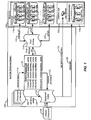
- FIG. 1 The high-level architecture of a particular implementation of an Automatic Deployment System (ADS) capable of configuring, deploying, and managing network resources for a cloud-based service (e.g., a telephony service such as that described above) will now be described with reference to FIG. 1 .
- ADS Automatic Deployment System
- FIG. 1 the term “automatic” should not be interpreted to mean that deployment occurs without human interaction. Rather, it will become clear with reference to the description below that human involvement in the configuration, deployment and management of network services and/or resources is advantageously facilitated through the selective automation of various aspects of those tasks. And it is again worth noting that network services and/or resources may be configured, deployed, and managed for any type of service or system using a system like ADS 100.
- An environment 102 is a set of services, configurations, and dependencies, which may be implemented by software components and configuration files installed on resources.
- Resources 104 may include, for example, "bare metal" resources 106, e.g., actual computing hardware, as well as virtual resources, e.g., virtual machines (VMs) 108. These resources may be owned, associated with, or under control of different entities, e.g., resource pool 110 associated with communication service provider RingCentral, and resource pools 112 associated with third party platform-as-a-service (PaaS) providers #1 through #N.
- multiple services may be installed on the same resource, and services can be transferred across resources without changing the logical structure of the environment.
- Dependencies may include, for example, relationships between services, relationships between configurations, and relationships between services and configurations.
- a telephony service may require a voicemail service, which could be expressed in a dependency.
- the configuration of a service may depend on the configuration of another service, such as a common directory shared between the services, which could be expressed in another dependency.
- services, configurations, and dependencies, as well as the corresponding software components, configuration files, and resources may be expressed in static or dynamic Extensible Markup Language (XML) format, which would allow for the hierarchical and modular definition of environments.
- XML Extensible Markup Language
- Resources may interface with ADS 100 directly, or through cloud gateway 113, via various application programming interfaces (APIs).
- APIs application programming interfaces
- "bare metal" resource 106 and virtual resource (VM) 108 may be abstracted or virtualized at a service provider level and may interface with ADS 100 directly, or through cloud gateway 113, via virtual center (vCenter) API 115.
- "bare metal" resource 106 and virtual resource 108 may interface with ADS 100 directly, or through cloud gateway 113, via separate APIs.
- Third party PaaS resources may interface with ADS 100 directly, or through cloud gateway 113, via various platform APIs 117, 119.
- cloud gateway includes a main module connected to ADS 100 via cloud gateway API 121 and one or more connector modules which work with the API(s) of particular resources (e.g., APIs 115, 117, 119).
- Cloud gateway API 121 provides a set of operations for resources which may be used by environments during their lifecycles. Examples of such operations may include, for example, creating, deleting, rebooting, getting the state of, starting, stopping, and creating or deleting a snapshot of a resource. Other examples of such operations may include getting a list of resources, getting sizes of resources (e.g., CPU, RAM or storage capacity), getting a list of instance templates, uploading instance templates, deleting instance templates, and getting a list of snapshots.
- Dynamic resource pool 114 identifies all of the resources among resources 104 that are available for inclusion in any new or existing environment. Dynamic resource pool 114 provides a view of resources which is agnostic to the underlying software and hardware resources. Note that dynamic resource pool 114 may include information about whether or not a resource has been deployed, e.g., in deployed environment 116, or whether a resource is available, partially available, or unavailable. Dynamic resource pool 114 can also contain aggregate information about resources, such as, for example, the number of small, medium, and large servers available for deployment.
- the ADS may periodically request a list of available resources, or a list of changes in available resources, from resource pools, for example, using the cloud gateway API 121 or APIs connecting to resource pools (e.g., APIs 115, 117, 119), and automatically update the list of available resources (e.g., dynamic resource pool 114).
- the resource pools can notify the ADS of changes in resources, for example, through the cloud gateway using various APIs (e.g., APIs 115, 117, 119).
- dynamic resource pool 114 When a user of the ADS wishes to deploy a new environment or new resources to an existing environment, a resource request 118 is generated to dynamic resource pool 114, in response to which appropriate resources are provisioned 120 and identified to deployment engine 122.
- resources may be generated on the fly, e.g., new VMs may be instantiated. That is, dynamic resource pool 114 may be a dynamic pool of resources in which resources may be added in response to demand. This can be particularly advantageous from a cost perspective where third party PaaS resources are used in that they may be created and deployed as needed.
- resources may be added, deleted, or modified based on determinations by the resource pools or based on determinations by the ADS. For example, if a given resource pool is approaching load capacity, it may provision additional servers and notify the ADS of those servers. In another example, if the ADS determines that particular services are performing slower than expected, ADS could request additional resources and shift those services to those new resources.
- deployment engine 122 employs the open-source integration tool Chef as a foundation.
- Chef from Opscode is open source software under the Apache license 2.0 and provides a systems integration framework that facilitates configuration management of network infrastructure.
- Chef uses "cookbooks” or “recipes” to enable management of network resources by writing code rather than running commands.
- Chef also uses "libraries” to enable integration of network resources with applications, databases, LDAP directories, etc. For more information regarding Chef, please refer to http://www.opscode.com/chef/.
- Chef requires highly specialized knowledge and programming skills to manually configure and manage network resources.
- An ADS implemented as described herein provides one or more additional layers of abstraction and functionality on top of the Chef framework which allow a higher degree of automation in the configuration, deployment, and management of network resources without requiring the specialized knowledge or programing skills of the typical Chef user. This, in turn, enables cloud-based services and systems to be highly scalable, eliminating a critical bottleneck in meeting rapidly increasing demand.
- Chef is merely one example of a systems integration framework upon which implementations of an ADS may be built. Others examples include Puppet Enterprise and AutomateIt.
- Scenarios and/or configurations 124 include specifications of what services and configurations will be used in a deployment, as well as any dependencies between them, all of which may be implemented as software components and configuration files installed on resources.
- Deployment engine 122 receives the scenarios/configurations 124, the provisioned resources 120, and any software components 126 to be integrated with the resources, and deploys the environment 128.
- Software components 126 might correspond, for example, to any of the various aspects of the services being deployed on the network resources, such as installation packages, programs, or scripts, and configuration files (including dependencies).
- Deployment engine 122 then verifies that the deployment was correct and successful, and once verified, changes the environment status from "not deployed” to "deployed,” or possibly even “live.”
- deployment engine 122 also provides a load balancer configuration 130 to common layer 132.
- Common layer 132 may correspond, for example, to a set of resources that is shared by multiple environments.
- ADS 100 supports "continuous integration,” i.e., the configuration, deployment, and/or management of network resources and software components without interruption of services. This may be accomplished, for example, by migrating services and users from one environment to another, i.e., "hot swapping" a currently active environment with an updated version of that environment.
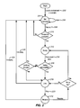
- the flowchart of FIG. 2 illustrates the lifecycle of an environment or one or more services (i.e., referred to herein as a scenario) according to a particular implementation of the ADS.
- the user creates an environment or scenario from scratch, from a template, or by cloning it from one of the existing environments (202).
- the user may choose between a fixed deployment or an auto deployment. If fixed deployment is chosen, the user may specify any part of the environment or scenario, e.g., services, configurations, dependencies, software components, resources, software component to resource mappings, etc.
- the ADS will specify some or all of these parts of the environment or scenario, e.g., based on existing services, configurations, dependencies (e.g., software component dependencies), available resources, etc. At this point, the environment or scenario is in the "not deployed" state (204).
- the environment or scenario can be edited (206) until the user wishes to deploy it.
- the ADS checks the dynamic resource pool for necessary resources (210), and locks them for use. If insufficient resources are available, the ADS reports this to the user and returns the environment or scenario to the "not deployed" state (204).
- the system could initiate the creation of additional resources, or resource pools could initiate the creation of additional resources in response to requests by the ADS. If, on the other hand, the ADS has all necessary resources the deployment process begins, at which point the ADS activates the deployed environment or scenario ("ready" state 212) and runs all necessary post-install tests 214.
- the deployed environment or scenario may be used and its state is changed to the "live" state (218) in which it becomes operational and is used for its target purpose, e.g., to provide cloud-based services. Otherwise, the ADS reports the test failure(s) to the user and may return the environment or scenario to the "not deployed" state (204).
- the state of the environment or scenario becomes "stopped” (222).
- This may be useful where, for example, an environment or scenario employs third party resources which, when operating, represent cost, i.e., when the resources of an environment or scenario are not being utilized, operation of the environment or scenario may be paused.
- This state may have various implications for the underlying network resources. For example, the operation of "bare metal" servers in a deployed environment or scenario might not literally be stopped, but might instead take one of three states, e.g., "ready,” “live,” or “not deployed.”
- the ADS might run a shutdown procedure that saves images of the VMs to storage.
- the ADS undeploys the environment or scenario (224) and returns it to the "not deployed” state (204). Similarly, if a live environment or scenario is no longer needed it may be undeployed (224).
- the ADS deletes all saved images of VMs registered for the environment or scenario, releases and/or reformats all "bare metal" servers registered for the environment or scenario, and returns all resources to the dynamic resource pool.
- An environment or scenario may also be returned to the "ready" state (212), e.g., for rerunning post-install tests, or to the "live” state (218), e.g., to resume normal operation.
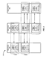
- FIG. 3 shows a communication system 300 which can be, for example, a cloud-based telephony system.
- Communication system 300 includes data centers 301, 302, and 303.
- Each data center is a point of presence (POP) that includes the network resources (e.g., servers, routers, switches, network connections, etc.) necessary to support the services provided by communication system 300.
- POP point of presence
- Each data center is typically located in a different geographical region.
- communication system 300 includes three user points of data (pods), i.e., pods 1, 2 and 3, each of which is a logical grouping of two or more pod units situated in different data centers. Each pod serves a different subset of user accounts.
- each pod unit e.g., unit 2A
- serves the same subset of users as the other pod units within the same pod e.g., pod units 2B and 2C.
- Each pod unit includes a communication server 319a-319g configured to provide substantially the same services to the same subset of users as the other pod units within the same pod.
- Each pod unit also includes an account database 321a-321g configured to support the respective communication servers for the corresponding subset of users.
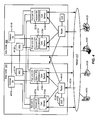
- FIG. 4 shows various components of communication system 300 of FIG. 3 . Specifically, FIG. 4 shows the various interconnections within and between data centers 301 and 302. Both data centers are in communication with network 417. Service requests from various communication devices 443A-443D are routed through network 417 to either or both of the data centers.
- Data center 301 includes pod units 1A and 2A, a common database (CDB) 407A, a message storage system (MSS) 411A, a router 413A, and a global user directory (GUD) 415A. Additional pod units (not shown) may also be included in data center 301.
- Data center 302 is similarly configured and includes components that operate substantially the same as those in data center 301. Data centers 301 and 302 provide backup and redundancy to one another in the event of failure.
- Communication servers 319 provide telecommunication services (e.g., voice, video, email, and/or facsimile) to corresponding subsets of users. Each server 319 may also provide other services including, for example, user account management and configuration, billing services, accounting services, etc.
- Each pod unit includes an account database 321 to support the communication server(s) for that particular pod unit, storing configuration details and other information regarding each user's account.
- Data center 301 includes router 413A to receive an incoming service request 431A from network 417.
- Router 413A parses the incoming service request to identify or extract a user key and queries GUD 415A to determine which pod is associated with the user key. Once the associated pod has been identified router 413A routes the service request to the pod unit in the data center associated with the identified pod. If the pod unit associated with the identified pod is not associated with data center 301, router 413A may route the service request to another data center (e.g., data center 302 as indicated by the arrow 441 A).
- another data center e.g., data center 302 as indicated by the arrow 441 A.
- Each pod unit of the data center 301 is also coupled to MSS 411A which stores files for the users served by pod units 1A and 2A. These files may include, for example, messages (e.g., voicemails and facsimiles), user logs, system messages, system and user call prompts (e.g., auto-attendant or user-recorded greetings), and other types of call-related or electronic messages.
- the contents of MSS 411A are synchronized with other data centers (e.g., synchronized with MSS 411B of data center 302).
- Each pod unit in data center 301 is coupled to common database 407A which stores shared data for all of the pods, and stores consolidated information from account databases 321.
- Common database 407A also facilitates changes to the pod databases.
- common database 407A may store data for applications that provide the services on communication servers 319. Different versions of the applications data may be stored in common database 407A which allow changes and upgrades to communication servers 319 to be implemented efficiently and conveniently. Changes may be made to common database 407A and propagated to pod units 1A and 2A.
- Common database 407A is synchronized across data centers to other common databases (e.g., common database 407B of data center 302).
- Common database 407A, MSS 411A, router 413A, and GUD 415A form a common layer of resources that are shared by all pod units in data center 301.
- the logical structure of an environment may be fixed to varying degrees (from the user's perspective) to facilitate the configuration, deployment, and management of a particular type of system or service set such as the communication system described above.
- the user's options in specifying or selecting elements of the structure may be constrained to achieve a desired level of uniformity of the environments deployed.
- the use of XML to define the logical structure of the environment allows the user to define a hierarchical and modular configuration of services and configurations, which may be easily stored, versioned, and updated in a source code repository.
- Tables 1-7 An example of the logical structure of an environment and deployment information similar to those discussed above with reference to FIGs. 3 and 4 is illustrated in Tables 1-7 below in which the various levels of an environment hierarchy are defined.
- the structure of an environment may itself be specified using the ADS.
- Such implementations would allow an ADS to be customizable so that it might be used to configure, deploy, and manage network resources for a wider variety of different types of services and systems.
- FIG. 5 is a flow diagram illustrating the relationship among user interface screens of an ADS that enables configuration, deployment, and management of environments of a cloud-based communication system such as the one described above with reference to FIGs. 3-4 and Tables 1-7.
- FIGs. 6-13 provide examples of the UI screens and the options presented to the user. Note that, with the exception of the login screen, a user can reach any list or add screen from the navigation menu shown at the right of several of the interfaces. Also note that a deployment sequence initiated using such interfaces can be asynchronous for a service or group of services, and can be synchronous between services or among a defined group of services.
- the sequence by which services or groups of services are be deployed may be specified in the ADS using a deployment configuration file, ADS database, or similar data structure.
- a deployment configuration file may specify that common layer services are deployed synchronously prior to user-specific services such as message services, but the message services are deployed asynchronously with respect to each other.
- a deployment configuration file may define groups of services that can be deployed asynchronously with respect to the services in each group, as well as a sequence for the groups of services to be deployed synchronously.
- the default screen is the Deployed Environments List screen 502 shown in FIG. 6 in which environments in various stages of the environment lifecycle (e.g., see FIG. 2 ) are listed.
- environments in various stages of the environment lifecycle e.g., see FIG. 2
- Various action options are available to the user for the listed environments depending on the current state of each including, for example, deploy, stop, undeploy, etc.
- a Deployed Environments Details screen 504A shown in FIG. 7 is reached by selecting one of the listed environments.
- the logical structure of the environment is shown, i.e., data centers (POPs), pods, pod units, etc., including the services associated with each pod unit.
- An alternative view is provided in screen 504B of FIG. 8 in which the servers associated with each pod unit are displayed instead of the services.
- POPs data centers
- FIG. 8 An alternative view is provided in screen 504B of FIG. 8 in which the servers associated with each pod unit are displayed instead of the services.
- a variety of user actions are available for various levels of the logical hierarchy including the ability to set databases to read only, start or stop a particular resource, to activate or deactivate a portion of the structure, or to migrate users, e.g., from one pod unit in a pod to another.
- a variety of actions are also available at the environment level to change the state of the environment including, for example, updating or editing the environment, various types of deployment of the environment (e.g., live or off-line), starting or stopping the environment (including scheduling of starts and stops), undeployment of an environment, etc.
- One environment-level option enables the migration of users from one environment to another which might be used, for example, when an environment needs to be taken offline or replaced by an updated or otherwise modified version. This allows such actions to be taken without interruption of service to the affected users.
- Environment Templates List screen 510 of FIG. 9 provides the user with a list of available template environments (i.e., templates) from which a new environment may be created and configured. Selection of one of the templates results in presentation of Environment Modification screen 512 of FIG. 10 in which the user may create a new environment. The user may also reach this screen to modify an existing environment by selecting, for example, the "edit" option in the Deployed Environment Details screens 504A and 504B discussed above with reference to FIGs. 7 and 8 .
- Add Service Popup screen 516 by which the user may select a service to add to the environment is presented in response to selection of the add service type options in screen 512.
- Add/Change Server Popup screen 514 is presented in response to the selection of the set server option in screen 512, and allows the user to add servers from among a list of available "bare metal" and virtual servers, the list of which may be filtered by different attributes, such server type or size.
- the logical structure of the selected template or environment is relatively fixed with the user's options being largely constrained to adding pod units to a pod and services to a pod unit (including specification of a load balancing pool).
- the user may modify any part of the logical structure of the selected template or environment, which can then be saved as a new template or environment.
- Resources List screen 518 of FIG. 11 provides a view to the user of all available resources in the dynamic resource pool (e.g., dynamic resource pool 114 of FIG. 1 ). Both "bare metal" and virtual resources may be added to the pool using Resource Creation/Modification screen 520 which may be reached by selecting "Add new" or a particular one of the existing resources in screen 518.
- a locations list can be used to filter the list of available resources based on the physical locations of resources.
- Users List screen 522 of FIG. 12 facilitates management of user permissions for users authorized to configure, deploy, and manage environments and network resources using an ADS and, in particular, allows an authorized user to grant, remove or modify permissions to create environments on a user-specific basis.
- ADS Logs screen 524 of FIG. 13 provides a view to the user of events associated with various environments organized, in this example, by time.
- the user may search or filter the log entries by description, date (e.g., by specifying a window of time), event level (e.g., debug, info, warning, error, critical), user, or environment. This enables the user to reduce the log entries to only those of interest.
- event level e.g., debug, info, warning, error, critical
- FIG. 14 illustrates the manner in which information flows according to a particular implementation of an ADS 1400.
- One or more ADS core servers 1452 employ a Web user interface 1454 to enable user interaction with ADS engine 1456.
- Web UI 1454 is based on Django, an open source web application framework written in Python.
- UI 1454 may be configured, for example, to provide user interfaces such as those discussed above with reference to FIGs. 5-13 .
- One or more ADS data stores 1458 are PostgreSQL systems, object-relational management systems used for storing data used by ADS 1400 (e.g., environments configurations, users, etc.), as well as jobs run by ADS 1400.
- ADS 1400 includes one or more Chef servers 1460 to support deployment of environments.
- ADS 1400 also includes one or more RabbitMQ servers 1462 to support message exchange, e.g., between ADS core server 1452 and other servers in the system.
- One or more Chef client servers 1464 instantiate and run chef clients 1466 which are responsible for retrieving environment templates from Apache Subversion (SVN) server(s) 1468 and software components, such as installation packages, programs, or scripts from Builder server(s) 1470.
- Apache Subversion (SVN) server(s) 1468 Apache Subversion
- software components such as installation packages, programs, or scripts from Builder server(s) 1470.
- an ADS may be designed for high availability.
- separate ADS instances may be used to configure, deploy and manage different types of environments, e.g., test environments, pre-production environments, and production environments.
- Redundancy of system components within an ADS e.g., ADS core servers, ADS data stores, Chef servers, RabbitMQ servers, etc.
- CARP Common Address Redundancy Protocol
- distributed storage e.g., using Distributed Replicated Block Devices (DRBDs) or Network-attached Storage (NAS).
- DRBDs Distributed Replicated Block Devices
- NAS Network-attached Storage
- ADS core server 1452 also queries RabbitMQ server 1462 for creating a pool of messages (1403).
- Message pool 1472 polls demon 1474 on Chef client server 1464 (1404) which starts chef client 1466 on the Chef client server (1405).
- Chef client 1466 retrieves the role and cookbook or recipe from Chef server 1460 (1406).
- Chef client 1466 also retrieves software components from Builder server 1470 and environment template configurations 1476 from SVN server 1468 (1407).
- An exit status is returned from Chef client 1466 to demon 1474 (1408), which places the exit status on the message bus of RabbitMQ server 1462 (1409).
- the exit status message is then returned to ADS engine 1456 (1410), written into data store 1458 (1411), and returned to UI 1454 (1412).
- an ADS designed as described herein may be used to configure, deploy, and manage network resources in a variety of homogeneous and heterogeneous network contexts to support wide variety of systems and network-based services including, for example, cloud-based systems and services. It follows then that the scope of the invention is not limited to any particular type of network or network topology, or to particular types or configurations of computing devices. This is true with respect to the nature of the network and computing devices in which and onto which systems and services are configured, deployed, and managed with an ADS, as well as the network and computing devices in and on which the ADS operates to facilitate the configuration, deployment, and management of network resources to support such systems and services.
- the computer program instructions with which embodiments of the invention may be implemented may correspond to any of a wide variety of programming languages and software tools, and be stored in any type of volatile or nonvolatile, non-transitory computer-readable storage medium or memory device, and may be executed according to a variety of computing models including, for example, a client/server model, a peer-to-peer model, on a stand-alone computing device, or according to a distributed computing model in which various of the functionalities described herein may be effected or employed at different locations.
Description
- The present application claims priority to
U.S. Patent Application No. 13/418,181 - The present invention relates to systems and methods for deploying network resources in heterogeneous network environments to support, for example, cloud-based services.
- The term "cloud computing" refers to computing models for enabling ubiquitous, convenient, on-demand network access to a shared pool of configurable computing resources (e.g., networks, servers, storage, applications, and services). Cloud-based services are rapidly becoming the primary way in which services are provided to businesses and consumers over the Internet and the World Wide Web.
- The predominant way in which such resources are configured, deployed, and managed today involves the manual configuration, deployment, and management of individual system resources. This may not present an issue when the number of resources is small, e.g., 5 or 10 servers. However, as a cloud-based service or suite of services scales to meet increased customer demand, e.g., hundreds or thousands of servers across multiple geographically distinct colocations, manual techniques become a serious bottleneck to the scalability and delivery of such services.
- In addition, manual deployment of network resources requires a relatively high level of programming skill and a detailed knowledge of the current configuration of deployed resources and, due to the complexity of the tasks involved, often requires time consuming trial-and-error troubleshooting of resource components and parameters before deployment is successful. The level of professional skill and institutional knowledge required for such key activities also represents a single point of failure from a system perspective, e.g., when a key employee moves on. These are undesirable technical and economic barriers to the deployment of cloud-based services.
- US Patent application
US2010/153527 A1 describes a network engineering automation system. - According to the present invention, methods, apparatus, systems, and computer program products are provided for deploying one or more network-based services in a network. According to various embodiments, one or more user interfaces configured to facilitate specification of at least a portion of a logical structure of an environment by a user are provided. The logical structure of the environment interrelates the one or more network-based services and one or more corresponding configurations. The one or more network services and the one or more configurations are to be implemented by one or more network resources and one or more software components. The one or more network resources are selected from a pool of available network resources. The one or more network resources are removed from the pool of available network resources. The one or more network resources are allocated to the environment with reference to the logical structure of the environment. The one or more network resources and the one or more software components are deployed to the network with reference to the logical structure of the environment, thereby enabling provision of the one or more services.
- According to some embodiments, the one or more user interfaces are further configured to enable the user to initiate deployment of the environment, and allocation of the one or more network resources and the one or more software components occurs in response to the initiation of the deployment of the environment.
- According to some embodiments, the one or more user interfaces are further configured to enable the user to initiate provision of the one or more services once the environment has been deployed even where one or more tests of the environment failed.
- According to some embodiments, the one or more user interfaces are further configured to enable the user to initiate undeployment of the environment, and the one or more network resources are returned to the pool of available network resources in response to undeployment of the environment.
- According to some embodiments, the one or more user interfaces are further configured to enable the user to initiate pausing of operation of the environment, and provision of the one or more services is stopped in conjunction with the pausing of the operation of the environment.
- According to some embodiments, the environment includes an updated version of a previously deployed environment, the previously deployed environment having a plurality of end users associated therewith, and the one or more user interfaces are further configured to enable the user to initiate migration of a subset of the end users from the previously deployed environment to the environment without interrupting provision of the one or more services to the subset of the end users.
- According to some embodiments, the pool of available network resources includes both hardware computing resources and software computing resources, and the allocation and deployment of the one or more network resources is accomplished using the hardware and software computing resources interchangeably.
- According to some embodiments, the environment interrelates a plurality of the network resources and a plurality of the software components. The plurality of network resources are situated in a plurality of geographically distinct data centers, and the logical structure of the environment includes one or more logical groupings of the network resources or software components across the geographically distinct data centers.
- According to some embodiments, the environment interrelates a plurality of the network resources and a plurality of the software components, and the plurality of network resources employ a plurality of different operating systems to provide the one or more services.
- According to some embodiments, the one or more user interfaces are further configured to enable the user to select an environment template in which the user may specify the portion of the logical structure of the environment, the environment template specifying a remainder of the logical structure of the environment.
- According to some embodiments, the one or more network resources by which the one or more network-based services and one or more configurations are implemented are modified.
- A further understanding of the nature and advantages of the present invention may be realized by reference to the remaining portions of the specification and the drawings.
-
-
FIG. 1 is a simplified system diagram of a particular implementation of a deployment system. -
FIG. 2 is a flowchart illustrating the lifecycle of an environment or scenario configured, deployed and managed by a particular implementation of a deployment system. -
FIGs. 3 and4 are simplified block diagrams of an example of a communication system in which network resources may be deployed using a particular implementation of a deployment system. -
FIG. 5 is a diagram illustrating the relationship among user interface screens of a particular implementation of a deployment system. -
FIGs. 6-13 are examples of the user interface screens ofFIG. 5 . -
FIG. 14 is a simplified system diagram of a particular implementation of a deployment system. - Reference will now be made in detail to specific embodiments of the invention including the best modes contemplated by the inventors for carrying out the invention. Examples of these specific embodiments are illustrated in the accompanying drawings. While the invention is described in conjunction with these specific embodiments, it will be understood that it is not intended to limit the invention to the described embodiments. On the contrary, it is intended to cover alternatives, modifications, and equivalents as may be included within the spirit and scope of the invention as defined by the appended claims. In the following description, specific details are set forth in order to provide a thorough understanding of the present invention. The present invention may be practiced without some or all of these specific details. In addition, well known features may not have been described in detail to avoid unnecessarily obscuring the invention.
- Embodiments of the present invention provide methods, apparatus, systems and computer program products which simplify and/or automate many of the tasks associated with the configuration, deployment, and management of network resources (including both computing resources and software) to support network services, e.g., cloud-based services. Such methods, systems and computer program products provide user interfaces that support the discovery, configuration, deployment, and management of network services and resources including, in some implementations, deployment of services and/or resources without interruption of currently operating systems and/or the delivery of services.
- Various implementations are described herein in the context cloud-based communication services, e.g., telephony and fax services. However, it should be understood that the scope of the invention is much broader, encompassing a wide variety of systems and services provided using virtually any network-based computing paradigm. To be clear, the techniques described herein may be used to support any type of network or cloud-based service or set of services. Therefore, references to specific applications herein are not intended and should not be used to limit the scope of the invention.
- The high-level architecture of a particular implementation of an Automatic Deployment System (ADS) capable of configuring, deploying, and managing network resources for a cloud-based service (e.g., a telephony service such as that described above) will now be described with reference to
FIG. 1 . It should be noted that the term "automatic" should not be interpreted to mean that deployment occurs without human interaction. Rather, it will become clear with reference to the description below that human involvement in the configuration, deployment and management of network services and/or resources is advantageously facilitated through the selective automation of various aspects of those tasks. And it is again worth noting that network services and/or resources may be configured, deployed, and managed for any type of service or system using a system like ADS 100. - The main object with which ADS 100 operates and the user interacts is referred to as an "environment." An
environment 102 is a set of services, configurations, and dependencies, which may be implemented by software components and configuration files installed on resources.Resources 104 may include, for example, "bare metal"resources 106, e.g., actual computing hardware, as well as virtual resources, e.g., virtual machines (VMs) 108. These resources may be owned, associated with, or under control of different entities, e.g.,resource pool 110 associated with communication service provider RingCentral, andresource pools 112 associated with third party platform-as-a-service (PaaS)providers # 1 through #N. According to various implementations, multiple services may be installed on the same resource, and services can be transferred across resources without changing the logical structure of the environment. - Dependencies may include, for example, relationships between services, relationships between configurations, and relationships between services and configurations. For example, a telephony service may require a voicemail service, which could be expressed in a dependency. In another example, the configuration of a service may depend on the configuration of another service, such as a common directory shared between the services, which could be expressed in another dependency. In some implementations, services, configurations, and dependencies, as well as the corresponding software components, configuration files, and resources, may be expressed in static or dynamic Extensible Markup Language (XML) format, which would allow for the hierarchical and modular definition of environments.
- Resources may interface with
ADS 100 directly, or throughcloud gateway 113, via various application programming interfaces (APIs). For example, "bare metal"resource 106 and virtual resource (VM) 108 may be abstracted or virtualized at a service provider level and may interface withADS 100 directly, or throughcloud gateway 113, via virtual center (vCenter)API 115. In another example, "bare metal"resource 106 andvirtual resource 108 may interface withADS 100 directly, or throughcloud gateway 113, via separate APIs. Third party PaaS resources may interface withADS 100 directly, or throughcloud gateway 113, viavarious platform APIs - According to a particular implementation, cloud gateway includes a main module connected to
ADS 100 viacloud gateway API 121 and one or more connector modules which work with the API(s) of particular resources (e.g.,APIs Cloud gateway API 121 provides a set of operations for resources which may be used by environments during their lifecycles. Examples of such operations may include, for example, creating, deleting, rebooting, getting the state of, starting, stopping, and creating or deleting a snapshot of a resource. Other examples of such operations may include getting a list of resources, getting sizes of resources (e.g., CPU, RAM or storage capacity), getting a list of instance templates, uploading instance templates, deleting instance templates, and getting a list of snapshots. -
Dynamic resource pool 114 identifies all of the resources amongresources 104 that are available for inclusion in any new or existing environment.Dynamic resource pool 114 provides a view of resources which is agnostic to the underlying software and hardware resources. Note thatdynamic resource pool 114 may include information about whether or not a resource has been deployed, e.g., in deployedenvironment 116, or whether a resource is available, partially available, or unavailable.Dynamic resource pool 114 can also contain aggregate information about resources, such as, for example, the number of small, medium, and large servers available for deployment. - According to some implementations, the ADS may periodically request a list of available resources, or a list of changes in available resources, from resource pools, for example, using the
cloud gateway API 121 or APIs connecting to resource pools (e.g.,APIs APIs - When a user of the ADS wishes to deploy a new environment or new resources to an existing environment, a
resource request 118 is generated todynamic resource pool 114, in response to which appropriate resources are provisioned 120 and identified todeployment engine 122. According to some implementations, ifdynamic resource pool 114 does not include sufficient resources to fulfill the resource request, resources may be generated on the fly, e.g., new VMs may be instantiated. That is,dynamic resource pool 114 may be a dynamic pool of resources in which resources may be added in response to demand. This can be particularly advantageous from a cost perspective where third party PaaS resources are used in that they may be created and deployed as needed. More specifically, resources may be added, deleted, or modified based on determinations by the resource pools or based on determinations by the ADS. For example, if a given resource pool is approaching load capacity, it may provision additional servers and notify the ADS of those servers. In another example, if the ADS determines that particular services are performing slower than expected, ADS could request additional resources and shift those services to those new resources. - According to a particular implementation,
deployment engine 122 employs the open-source integration tool Chef as a foundation. Chef from Opscode is open source software under the Apache license 2.0 and provides a systems integration framework that facilitates configuration management of network infrastructure. Chef uses "cookbooks" or "recipes" to enable management of network resources by writing code rather than running commands. Chef also uses "libraries" to enable integration of network resources with applications, databases, LDAP directories, etc. For more information regarding Chef, please refer to http://www.opscode.com/chef/. - Conventionally used, Chef requires highly specialized knowledge and programming skills to manually configure and manage network resources. An ADS implemented as described herein provides one or more additional layers of abstraction and functionality on top of the Chef framework which allow a higher degree of automation in the configuration, deployment, and management of network resources without requiring the specialized knowledge or programing skills of the typical Chef user. This, in turn, enables cloud-based services and systems to be highly scalable, eliminating a critical bottleneck in meeting rapidly increasing demand. It should be noted that Chef is merely one example of a systems integration framework upon which implementations of an ADS may be built. Others examples include Puppet Enterprise and AutomateIt.
- Referring back to
FIG. 1 , the user specifies scenarios (i.e., one or more services) and/or configurations for the requested resources and requests deployment. Scenarios and/orconfigurations 124 include specifications of what services and configurations will be used in a deployment, as well as any dependencies between them, all of which may be implemented as software components and configuration files installed on resources.Deployment engine 122 receives the scenarios/configurations 124, the provisionedresources 120, and anysoftware components 126 to be integrated with the resources, and deploys theenvironment 128.Software components 126 might correspond, for example, to any of the various aspects of the services being deployed on the network resources, such as installation packages, programs, or scripts, and configuration files (including dependencies).Deployment engine 122 then verifies that the deployment was correct and successful, and once verified, changes the environment status from "not deployed" to "deployed," or possibly even "live." In the implementation shown,deployment engine 122 also provides aload balancer configuration 130 tocommon layer 132.Common layer 132 may correspond, for example, to a set of resources that is shared by multiple environments. - According to some implementations,
ADS 100 supports "continuous integration," i.e., the configuration, deployment, and/or management of network resources and software components without interruption of services. This may be accomplished, for example, by migrating services and users from one environment to another, i.e., "hot swapping" a currently active environment with an updated version of that environment. - The flowchart of
FIG. 2 illustrates the lifecycle of an environment or one or more services (i.e., referred to herein as a scenario) according to a particular implementation of the ADS. The user creates an environment or scenario from scratch, from a template, or by cloning it from one of the existing environments (202). According to a particular implementation, the user may choose between a fixed deployment or an auto deployment. If fixed deployment is chosen, the user may specify any part of the environment or scenario, e.g., services, configurations, dependencies, software components, resources, software component to resource mappings, etc. If auto deployment is chosen, the ADS will specify some or all of these parts of the environment or scenario, e.g., based on existing services, configurations, dependencies (e.g., software component dependencies), available resources, etc. At this point, the environment or scenario is in the "not deployed" state (204). - In the "not deployed" state the environment or scenario can be edited (206) until the user wishes to deploy it. In response to a "deploy" request (208), the ADS checks the dynamic resource pool for necessary resources (210), and locks them for use. If insufficient resources are available, the ADS reports this to the user and returns the environment or scenario to the "not deployed" state (204). Alternatively, or in addition, the system could initiate the creation of additional resources, or resource pools could initiate the creation of additional resources in response to requests by the ADS. If, on the other hand, the ADS has all necessary resources the deployment process begins, at which point the ADS activates the deployed environment or scenario ("ready" state 212) and runs all necessary
post-install tests 214. If the post-install tests are successful (216) the deployed environment or scenario may be used and its state is changed to the "live" state (218) in which it becomes operational and is used for its target purpose, e.g., to provide cloud-based services. Otherwise, the ADS reports the test failure(s) to the user and may return the environment or scenario to the "not deployed" state (204). - Alternatively, there may be circumstances in which, even though the post-install tests are not entirely successful, the user may still want to allow the environment or scenario to go live. For example, during the testing phase of a particular environment or scenario configuration it may be useful to allow test engineers the flexibility to have an environment or scenario go live even though some of the post-install tests may have failed.
- If the user wants to stop operation of the environment or scenario (220), the state of the environment or scenario becomes "stopped" (222). This may be useful where, for example, an environment or scenario employs third party resources which, when operating, represent cost, i.e., when the resources of an environment or scenario are not being utilized, operation of the environment or scenario may be paused. This state may have various implications for the underlying network resources. For example, the operation of "bare metal" servers in a deployed environment or scenario might not literally be stopped, but might instead take one of three states, e.g., "ready," "live," or "not deployed." By contrast, for VMs, the ADS might run a shutdown procedure that saves images of the VMs to storage.
- If the user wants to modify a live environment or scenario in some way (e.g., change software component versions or configurations, add or change resources, etc.), the ADS undeploys the environment or scenario (224) and returns it to the "not deployed" state (204). Similarly, if a live environment or scenario is no longer needed it may be undeployed (224). When a deployed environment or scenario is undeployed (224 or 226), the ADS deletes all saved images of VMs registered for the environment or scenario, releases and/or reformats all "bare metal" servers registered for the environment or scenario, and returns all resources to the dynamic resource pool.
- An environment or scenario may also be returned to the "ready" state (212), e.g., for rerunning post-install tests, or to the "live" state (218), e.g., to resume normal operation.
- According to a particular implementation, an ADS is customized to facilitate deployment of network resources in a cloud-based communication system such as the one illustrated in
FIGs. 3 and4 .FIG. 3 shows acommunication system 300 which can be, for example, a cloud-based telephony system.Communication system 300 includesdata centers communication system 300. Each data center is typically located in a different geographical region. - In this example,
communication system 300 includes three user points of data (pods), i.e.,pods unit 2A) serves the same subset of users as the other pod units within the same pod (e.g.,pod units communication server 319a-319g configured to provide substantially the same services to the same subset of users as the other pod units within the same pod. Each pod unit also includes anaccount database 321a-321g configured to support the respective communication servers for the corresponding subset of users. -
FIG. 4 shows various components ofcommunication system 300 ofFIG. 3 . Specifically,FIG. 4 shows the various interconnections within and betweendata centers network 417. Service requests fromvarious communication devices 443A-443D are routed throughnetwork 417 to either or both of the data centers.Data center 301 includespod units router 413A, and a global user directory (GUD) 415A. Additional pod units (not shown) may also be included indata center 301.Data center 302 is similarly configured and includes components that operate substantially the same as those indata center 301.Data centers - Communication servers 319 provide telecommunication services (e.g., voice, video, email, and/or facsimile) to corresponding subsets of users. Each server 319 may also provide other services including, for example, user account management and configuration, billing services, accounting services, etc. Each pod unit includes an account database 321 to support the communication server(s) for that particular pod unit, storing configuration details and other information regarding each user's account.
-
Pod units Data center 301 includesrouter 413A to receive anincoming service request 431A fromnetwork 417.Router 413A parses the incoming service request to identify or extract a user key andqueries GUD 415A to determine which pod is associated with the user key. Once the associated pod has been identifiedrouter 413A routes the service request to the pod unit in the data center associated with the identified pod. If the pod unit associated with the identified pod is not associated withdata center 301,router 413A may route the service request to another data center (e.g.,data center 302 as indicated by thearrow 441 A). - Each pod unit of the
data center 301 is also coupled toMSS 411A which stores files for the users served bypod units MSS 411A are synchronized with other data centers (e.g., synchronized withMSS 411B of data center 302). - Each pod unit in
data center 301 is coupled tocommon database 407A which stores shared data for all of the pods, and stores consolidated information from account databases 321.Common database 407A also facilitates changes to the pod databases. For example,common database 407A may store data for applications that provide the services on communication servers 319. Different versions of the applications data may be stored incommon database 407A which allow changes and upgrades to communication servers 319 to be implemented efficiently and conveniently. Changes may be made tocommon database 407A and propagated topod units Common database 407A is synchronized across data centers to other common databases (e.g.,common database 407B of data center 302).Common database 407A,MSS 411A,router 413A, andGUD 415A form a common layer of resources that are shared by all pod units indata center 301. - For more information regarding the nature of such a system with which an ADS constructed as described herein may be used, please refer to
U.S. Patent Application No. 12/957,125 - According to some implementations, the logical structure of an environment (e.g., specified using XML, dynamic XML, databases, graphical design environments, etc.) may be fixed to varying degrees (from the user's perspective) to facilitate the configuration, deployment, and management of a particular type of system or service set such as the communication system described above. In such implementations, the user's options in specifying or selecting elements of the structure may be constrained to achieve a desired level of uniformity of the environments deployed. For example, the use of XML to define the logical structure of the environment allows the user to define a hierarchical and modular configuration of services and configurations, which may be easily stored, versioned, and updated in a source code repository. An example of the logical structure of an environment and deployment information similar to those discussed above with reference to
FIGs. 3 and4 is illustrated in Tables 1-7 below in which the various levels of an environment hierarchy are defined. -
Table 1 Attributes ID :== Unique unsigned integer Name :== String Type :== [Pro | Custom | Dev ] Subtype :== [QA | AppDev | StressTests] # only if Type==Dev, else empty CDB IDs :== Array of TNS # links to DBs in Common Layer Downlinks POD quantity :== Unsigned Integer # not 0 PODs :== Array of used PODs # elements are POD IDs -
Table 2 Attributes ID :== Unique unsigned integer Name :== String # from preconfigured list Downlinks UNITs :== Array of UNIT IDs # at least two elements -
Table 3 Attributes ID :== <POD ID>[ 1 | 2 ] Location :== String # POP name, preconfigured State :== [Active | Standby ] # Boolean Database ID :== TNS of ADB Downlinks Roles := Hash of used Service Roles -
Table 4 Attributes ID :== <POD ID><UNIT ID><Integer> Role Name :== String Role Description :== String Load Balancer using :== Boolean Downlinks Software Components :== Array of used RingCentral Software Components # elements are software ID. -
Table 5 Attributes ID :== Integer Name :== String Major version :== Integer Minor version :== Integer Branch ID :== Integer Branch Name :== String Commit number :== Integer OS compatability :== [ Win2K | Win2K3 | Win2K8 | RHEL | CentOS ] Configuration :== Hash Number :== Integer # Number of this component in Service Role Downlinks Server ID :== Integer # ServerID in Dynamic Resource Pool Major dependencies :== Array of RingCentral Software Components # elements are RingCentral Software Components IDs Minor dependencies :== Array of 3rd party Software Components # elements are RingCentral Software Components IDs -
Table 6 Attributes ID :== Integer Name :== String Major version :== Integer Minor version :== Integer Configuration :== Hash -
Table 7 Attributes ID :== Integer # ServerID in Dynamic Resource Pool Name :== String # Hostname Domain :== String # DNS right part IP :== IP address OS :== [Win2K | Win2K3 | Win2K8 | RHEL | CentOS ] Virtual mark :== Boolean Virtualization API type :== [VMWARE | AWS ] # only if Virtual mark is TRUE, else empty Size :== [ small | medium | large ] # server power indicator Priority :== Integer - According to other implementations, the structure of an environment may itself be specified using the ADS. Such implementations would allow an ADS to be customizable so that it might be used to configure, deploy, and manage network resources for a wider variety of different types of services and systems.
-
FIG. 5 is a flow diagram illustrating the relationship among user interface screens of an ADS that enables configuration, deployment, and management of environments of a cloud-based communication system such as the one described above with reference toFIGs. 3-4 and Tables 1-7.FIGs. 6-13 provide examples of the UI screens and the options presented to the user. Note that, with the exception of the login screen, a user can reach any list or add screen from the navigation menu shown at the right of several of the interfaces. Also note that a deployment sequence initiated using such interfaces can be asynchronous for a service or group of services, and can be synchronous between services or among a defined group of services. - According to some implementations, the sequence by which services or groups of services are be deployed may be specified in the ADS using a deployment configuration file, ADS database, or similar data structure. For example, a deployment configuration file may specify that common layer services are deployed synchronously prior to user-specific services such as message services, but the message services are deployed asynchronously with respect to each other. In another example, a deployment configuration file may define groups of services that can be deployed asynchronously with respect to the services in each group, as well as a sequence for the groups of services to be deployed synchronously.
- In the depicted implementation, when a user logs in, the default screen is the Deployed
Environments List screen 502 shown inFIG. 6 in which environments in various stages of the environment lifecycle (e.g., seeFIG. 2 ) are listed. Various action options are available to the user for the listed environments depending on the current state of each including, for example, deploy, stop, undeploy, etc. - A Deployed Environments Details screen 504A shown in
FIG. 7 is reached by selecting one of the listed environments. The logical structure of the environment is shown, i.e., data centers (POPs), pods, pod units, etc., including the services associated with each pod unit. An alternative view is provided inscreen 504B ofFIG. 8 in which the servers associated with each pod unit are displayed instead of the services. A variety of user actions are available for various levels of the logical hierarchy including the ability to set databases to read only, start or stop a particular resource, to activate or deactivate a portion of the structure, or to migrate users, e.g., from one pod unit in a pod to another. - A variety of actions are also available at the environment level to change the state of the environment including, for example, updating or editing the environment, various types of deployment of the environment (e.g., live or off-line), starting or stopping the environment (including scheduling of starts and stops), undeployment of an environment, etc. One environment-level option enables the migration of users from one environment to another which might be used, for example, when an environment needs to be taken offline or replaced by an updated or otherwise modified version. This allows such actions to be taken without interruption of service to the affected users.
- Environment
Templates List screen 510 ofFIG. 9 provides the user with a list of available template environments (i.e., templates) from which a new environment may be created and configured. Selection of one of the templates results in presentation ofEnvironment Modification screen 512 ofFIG. 10 in which the user may create a new environment. The user may also reach this screen to modify an existing environment by selecting, for example, the "edit" option in the Deployed Environment Details screens 504A and 504B discussed above with reference toFIGs. 7 and8 . - Add
Service Popup screen 516 by which the user may select a service to add to the environment is presented in response to selection of the add service type options inscreen 512. Add/ChangeServer Popup screen 514 is presented in response to the selection of the set server option inscreen 512, and allows the user to add servers from among a list of available "bare metal" and virtual servers, the list of which may be filtered by different attributes, such server type or size. According to the implementation shown, the logical structure of the selected template or environment is relatively fixed with the user's options being largely constrained to adding pod units to a pod and services to a pod unit (including specification of a load balancing pool). In other implementations, the user may modify any part of the logical structure of the selected template or environment, which can then be saved as a new template or environment. -
Resources List screen 518 ofFIG. 11 provides a view to the user of all available resources in the dynamic resource pool (e.g.,dynamic resource pool 114 ofFIG. 1 ). Both "bare metal" and virtual resources may be added to the pool using Resource Creation/Modification screen 520 which may be reached by selecting "Add new" or a particular one of the existing resources inscreen 518. A locations list can be used to filter the list of available resources based on the physical locations of resources. -
Users List screen 522 ofFIG. 12 facilitates management of user permissions for users authorized to configure, deploy, and manage environments and network resources using an ADS and, in particular, allows an authorized user to grant, remove or modify permissions to create environments on a user-specific basis. - ADS Logs
screen 524 ofFIG. 13 provides a view to the user of events associated with various environments organized, in this example, by time. The user may search or filter the log entries by description, date (e.g., by specifying a window of time), event level (e.g., debug, info, warning, error, critical), user, or environment. This enables the user to reduce the log entries to only those of interest. -
FIG. 14 illustrates the manner in which information flows according to a particular implementation of anADS 1400. One or moreADS core servers 1452 employ aWeb user interface 1454 to enable user interaction withADS engine 1456. In the example shown,Web UI 1454 is based on Django, an open source web application framework written in Python.UI 1454 may be configured, for example, to provide user interfaces such as those discussed above with reference toFIGs. 5-13 . - One or more
ADS data stores 1458 are PostgreSQL systems, object-relational management systems used for storing data used by ADS 1400 (e.g., environments configurations, users, etc.), as well as jobs run byADS 1400. As discussed above,ADS 1400 includes one ormore Chef servers 1460 to support deployment of environments.ADS 1400 also includes one ormore RabbitMQ servers 1462 to support message exchange, e.g., betweenADS core server 1452 and other servers in the system. One or moreChef client servers 1464 instantiate and runchef clients 1466 which are responsible for retrieving environment templates from Apache Subversion (SVN) server(s) 1468 and software components, such as installation packages, programs, or scripts from Builder server(s) 1470. - According to some implementations, an ADS may be designed for high availability. For example, separate ADS instances may be used to configure, deploy and manage different types of environments, e.g., test environments, pre-production environments, and production environments. Redundancy of system components within an ADS (e.g., ADS core servers, ADS data stores, Chef servers, RabbitMQ servers, etc.) may be supported using, for example, the Common Address Redundancy Protocol (CARP) and distributed storage, e.g., using Distributed Replicated Block Devices (DRBDs) or Network-attached Storage (NAS). A wide variety of other high availability design techniques may be used to ensure the desired level of reliability and availability.
- Referring once again to
FIG. 14 , a query (1401), e.g., with the configuration of an environment, is transmitted fromUI 1454 toADS engine 1456 which queriesdata store 1458 for the state of the environment (1402).ADS core server 1452 also queriesRabbitMQ server 1462 for creating a pool of messages (1403).Message pool 1472polls demon 1474 on Chef client server 1464 (1404) which startschef client 1466 on the Chef client server (1405).Chef client 1466 retrieves the role and cookbook or recipe from Chef server 1460 (1406).Chef client 1466 also retrieves software components from Builder server 1470 andenvironment template configurations 1476 from SVN server 1468 (1407). An exit status is returned fromChef client 1466 to demon 1474 (1408), which places the exit status on the message bus of RabbitMQ server 1462 (1409). The exit status message is then returned to ADS engine 1456 (1410), written into data store 1458 (1411), and returned to UI 1454 (1412). - As mentioned above, an ADS designed as described herein may be used to configure, deploy, and manage network resources in a variety of homogeneous and heterogeneous network contexts to support wide variety of systems and network-based services including, for example, cloud-based systems and services. It follows then that the scope of the invention is not limited to any particular type of network or network topology, or to particular types or configurations of computing devices. This is true with respect to the nature of the network and computing devices in which and onto which systems and services are configured, deployed, and managed with an ADS, as well as the network and computing devices in and on which the ADS operates to facilitate the configuration, deployment, and management of network resources to support such systems and services.
- And despite references to particular computing paradigms and software tools herein, the computer program instructions with which embodiments of the invention may be implemented may correspond to any of a wide variety of programming languages and software tools, and be stored in any type of volatile or nonvolatile, non-transitory computer-readable storage medium or memory device, and may be executed according to a variety of computing models including, for example, a client/server model, a peer-to-peer model, on a stand-alone computing device, or according to a distributed computing model in which various of the functionalities described herein may be effected or employed at different locations.
- While the invention has been particularly shown and described with reference to specific embodiments thereof, it will be understood by those skilled in the art that changes in the form and details of the disclosed embodiments may be made. In addition, although various advantages, aspects, and objects of the present invention have been discussed herein with reference to various embodiments, it will be understood that the scope of the invention should not be limited by reference to such advantages, aspects, and objects. Rather, the scope of the invention should be determined with reference to the appended claims.
Claims (15)
- A computer-implemented method for deploying one or more network-based services in a network, comprising:providing one or more user interfaces (502-524, 1454) configured to facilitate specification of at least a portion of a logical structure (Tables 1-7) of an environment (102) by a user, the logical structure of the environment interrelating the one or more network-based services (319) and one or more corresponding configurations, the one or more network-based services (319) and the one or more configurations to be implemented by one or more network resources (104) and one or more software components (126), the one or more network resources (104) being selected from a pool (110, 112) of available network resources, the logical structure being organized in a hierarchy having a plurality of levels, each level of the hierarchy comprising one or more modular components, the logical structure including one or more dependencies among the modular components, the one or more services, and the one or more configurations, the one or more interfaces being configured to enable the user to take one or more actions with respect to the one or more modular components on multiple levels of the hierarchy, at least one of the one or more actions automatically propagating in the logical structure according to the one or more dependencies;removing (114) the one or more network resources (104) from the pool of available network resources;allocating (120) the one or more network resources (104) to the environment (102) with reference to the logical structure of the environment (102); anddeploying (122) the one or more network resources (104) and the one or more software components (126) to the network with reference to the logical structure of the environment (102), thereby enabling provision of the one or more network-based services.
- The method of claim 1 wherein the one or more user interfaces (502-524, 1454) are further configured to enable the user to initiate at least one of:deployment of the environment (102), and wherein allocating the one or more network resources (104) and the one or more software components (126) occurs in response to the initiation of the deployment of the environment (102);undeployment of the environment (102), the method further comprising returning the one or more network resources (104) to the pool of available network resources in response to undeployment of the environment (102);pausing of operation of the environment (102), the method further comprising stopping provision of the one or more network-based services (319) in conjunction with the pausing of the operation of the environment (102).
- The method of any preceding claim wherein the environment (102) comprises an updated version of a previously deployed environment, the previously deployed environment having a plurality of end users associated therewith, the one or more user interfaces (502-524, 1454) being further configured to enable the user to initiate migration of a subset of the end users from the previously deployed environment to the environment (102) without interrupting provision of the one or more network-based services (319) to the subset of the end users.
- The method of any preceding claim wherein the pool of available network resources (104) includes both hardware computing resources (106) and software computing resources (108), and wherein the allocation and deployment of the one or more network resources (104) is accomplished using the hardware and software computing resources interchangeably.
- The method of any preceding claim wherein the environment (102) interrelates at least one of:a plurality of the network resources (104) and a plurality of the software components (126), wherein the plurality of network resources are situated in a plurality of geographically distinct data centers, and wherein the logical structure of the environment (102) includes one or more logical groupings of the network resources or software components across the geographically distinct data centers;a plurality of the network resources (104) and a plurality of the software components (126), and wherein the plurality of network resources employ a plurality of different operating systems to provide the one or more network-based services.
- The method of any preceding claim wherein the one or more user interfaces (502-524, 1454) are further configured to enable the user to select an environment template in which the user may specify the portion of the logical structure of the environment (102), the environment template specifying a remainder of the logical structure of the environment (102).
- The method of any preceding claim further comprising modifying the one or more network resources (104) by which the one or more network-based services (319) and one or more configurations are implemented.
- A computer program product for deploying one or more network-based services (319) in a network, the computer program product comprising one or more non-transitory computer-readable media having computer program instructions stored therein and configured such that, when executed by one or more computing devices, cause the one or more computing devices to perform the method of any of claims 1-7.
- A system for deploying one or more network-based services (319) in a network, the system comprising one or more computing devices configured to perform the method of any of claims 1-7.
- A computer-implemented method for managing one or more network-based services (319) in a network, comprising:deploying one or more network resources (104) and one or more software components (126) to the network to implement the one or more network-based services (319) using a logical structure specifying an environment (102) for providing the network based services, the logical structure (Tables 1-7) interrelating the one or more network-based services (319) and one or more corresponding configurations, the logical structure being organized in a hierarchy having a plurality of levels, each level of the hierarchy comprising one or more modular components, the logical structure including dependencies among the modular components; andin response to a command to modify operation (512) of at least one of the one or more modular components corresponding to a particular level of the hierarchy, modifying operation of a corresponding subset of the one or more network resources (104) and the one or more software components (126) in accordance with the dependencies.
- The computer-implemented method of claim 10, wherein deploying the one or more network resources (104) and the one or more software components (126) to the network to implement the one or more network-based services (319) comprises effecting deployment in a specified sequence.
- The computer-implemented method of claim 11, wherein the specified sequence specifies either or both of a first group of services to be deployed asynchronously relative to each other, or a second group of services to be deployed synchronously relative to each other.
- The computer-implemented method of any of claims 10-12, wherein the command to modify operation of the at least one of the one or more modular components comprises at least one of:a command to start or stop operation of a server, a software component, a service, a group of services, or the environment (102);a command to stop operation of the at least one of the one or more modular components, the method further comprising, in response to a command to replace the at least one of the one or more modular components with an updated version of the at least one of the one or more modular components, modifying the logical structure of the environment (102) to include the updated version, and optionally further comprising, allocating one or more new network resources (104) or one or more new software components (126) for the updated version of the at least one of the one or more modular components;a command to stop operation of the at least one of the one or more modular components, the method further comprising migrating a population of users from the at least one of the one or more modular components to a different instance of the at least one of the one or more modular components.
- The computer-implemented method of any of claims 10-13 further comprising, starting or stopping operation of a particular one of the network resources (104) or a particular one of the software components (126) in response to a command to start or stop operation of the particular one of the network resources (104) or the particular one of the software components (126).
- A system or a computer program product for managing one or more network-based services (319) in a network, the system comprising one or more computing devices configured to perform the method of any of claims 10-14.
Applications Claiming Priority (2)
| Application Number | Priority Date | Filing Date | Title |
|---|---|---|---|
| US13/418,181 US8335851B1 (en) | 2012-03-12 | 2012-03-12 | Network resource deployment for cloud-based services |
| PCT/US2013/028626 WO2013138091A1 (en) | 2012-03-12 | 2013-03-01 | Network resource deployment for cloud-based services |
Publications (3)
| Publication Number | Publication Date |
|---|---|
| EP2825973A1 EP2825973A1 (en) | 2015-01-21 |
| EP2825973A4 EP2825973A4 (en) | 2015-02-25 |
| EP2825973B1 true EP2825973B1 (en) | 2015-10-14 |
Family
ID=47325343
Family Applications (1)
| Application Number | Title | Priority Date | Filing Date |
|---|---|---|---|
| EP13760815.4A Active EP2825973B1 (en) | 2012-03-12 | 2013-03-01 | Network resource deployment for cloud-based services |
Country Status (6)
| Country | Link |
|---|---|
| US (4) | US8335851B1 (en) |
| EP (1) | EP2825973B1 (en) |
| CN (1) | CN104272292B (en) |
| CA (1) | CA2867126C (en) |
| HK (1) | HK1200555A1 (en) |
| WO (1) | WO2013138091A1 (en) |
Families Citing this family (84)
| Publication number | Priority date | Publication date | Assignee | Title |
|---|---|---|---|---|
| US9026668B2 (en) | 2012-05-26 | 2015-05-05 | Free Stream Media Corp. | Real-time and retargeted advertising on multiple screens of a user watching television |
| US10631068B2 (en) | 2008-11-26 | 2020-04-21 | Free Stream Media Corp. | Content exposure attribution based on renderings of related content across multiple devices |
| US10880340B2 (en) | 2008-11-26 | 2020-12-29 | Free Stream Media Corp. | Relevancy improvement through targeting of information based on data gathered from a networked device associated with a security sandbox of a client device |
| US10567823B2 (en) | 2008-11-26 | 2020-02-18 | Free Stream Media Corp. | Relevant advertisement generation based on a user operating a client device communicatively coupled with a networked media device |
| US9519772B2 (en) | 2008-11-26 | 2016-12-13 | Free Stream Media Corp. | Relevancy improvement through targeting of information based on data gathered from a networked device associated with a security sandbox of a client device |
| US9986279B2 (en) | 2008-11-26 | 2018-05-29 | Free Stream Media Corp. | Discovery, access control, and communication with networked services |
| US9154942B2 (en) | 2008-11-26 | 2015-10-06 | Free Stream Media Corp. | Zero configuration communication between a browser and a networked media device |
| US10334324B2 (en) | 2008-11-26 | 2019-06-25 | Free Stream Media Corp. | Relevant advertisement generation based on a user operating a client device communicatively coupled with a networked media device |
| US10419541B2 (en) | 2008-11-26 | 2019-09-17 | Free Stream Media Corp. | Remotely control devices over a network without authentication or registration |
| US9961388B2 (en) | 2008-11-26 | 2018-05-01 | David Harrison | Exposure of public internet protocol addresses in an advertising exchange server to improve relevancy of advertisements |
| US8180891B1 (en) | 2008-11-26 | 2012-05-15 | Free Stream Media Corp. | Discovery, access control, and communication with networked services from within a security sandbox |
| US10977693B2 (en) | 2008-11-26 | 2021-04-13 | Free Stream Media Corp. | Association of content identifier of audio-visual data with additional data through capture infrastructure |
| US9386356B2 (en) | 2008-11-26 | 2016-07-05 | Free Stream Media Corp. | Targeting with television audience data across multiple screens |
| US10079716B2 (en) * | 2009-03-04 | 2018-09-18 | Amazon Technologies, Inc. | User controlled environment updates in server cluster |
| US8707111B2 (en) | 2011-02-09 | 2014-04-22 | Ebay Inc. | High-volume distributed script error handling |
| US8335851B1 (en) | 2012-03-12 | 2012-12-18 | Ringcentral, Inc. | Network resource deployment for cloud-based services |
| US8949930B1 (en) * | 2012-03-19 | 2015-02-03 | Amazon Technologies, Inc. | Template representation of security resources |
| JP5537600B2 (en) * | 2012-05-15 | 2014-07-02 | 株式会社Nttドコモ | Control node and communication control method |
| US8904402B2 (en) * | 2012-05-30 | 2014-12-02 | Red Hat, Inc. | Controlling capacity in a multi-tenant platform-as-a-service environment in a cloud computing system |
| US9003406B1 (en) * | 2012-06-29 | 2015-04-07 | Emc Corporation | Environment-driven application deployment in a virtual infrastructure |
| US9043786B1 (en) * | 2012-06-29 | 2015-05-26 | Emc Corporation | Blueprint-driven environment template creation in a virtual infrastructure |
| WO2014007810A1 (en) | 2012-07-03 | 2014-01-09 | Hewlett-Packard Development Company, L.P. | Managing a cloud service |
| US8978035B2 (en) | 2012-09-06 | 2015-03-10 | Red Hat, Inc. | Scaling of application resources in a multi-tenant platform-as-a-service environment in a cloud computing system |
| US9841929B1 (en) * | 2012-09-28 | 2017-12-12 | EMC IP Holding Company LLC | Distributed system software infrastructure |
| US9378064B2 (en) * | 2012-11-15 | 2016-06-28 | Bank Of America Corporation | Orchestration management of information technology |
| US20160285734A1 (en) * | 2012-11-21 | 2016-09-29 | Nec Corporation | Cloud-environment provision system, route control method, and medium |
| US9336118B2 (en) * | 2013-01-28 | 2016-05-10 | Hewlett Packard Enterprise Development Lp | Allocating test capacity from cloud systems |
| CN104937581A (en) * | 2013-01-31 | 2015-09-23 | 高通股份有限公司 | Providing access to information across multiple computing devices |
| US9628399B2 (en) * | 2013-03-14 | 2017-04-18 | International Business Machines Corporation | Software product instance placement |
| GB2512051A (en) * | 2013-03-18 | 2014-09-24 | Ibm | Robust service deployment |
| US9122804B2 (en) * | 2013-05-15 | 2015-09-01 | Oracle Internation Corporation | Logic validation and deployment |
| EP2852124A4 (en) * | 2013-07-09 | 2015-12-02 | Cloud Technology Ltd G | Resource deployment method for cloud computing environment |
| US8874755B1 (en) * | 2013-07-31 | 2014-10-28 | Splunk, Inc. | Provisioning of cloud networks with services |
| US9083653B2 (en) * | 2013-10-21 | 2015-07-14 | Hewlett-Packard Development Company, L.P. | Automated cloud set up |
| US9749257B2 (en) * | 2013-10-24 | 2017-08-29 | Kcura Llc | Method and apparatus for dynamically deploying software agents |
| EP3063663A4 (en) | 2013-10-30 | 2017-04-19 | Hewlett-Packard Enterprise Development LP | Stitching an application model to an infrastructure template |
| US11245588B2 (en) | 2013-10-30 | 2022-02-08 | Micro Focus Llc | Modifying realized topologies |
| EP3063657B1 (en) | 2013-10-30 | 2021-12-01 | Hewlett Packard Enterprise Development LP | Monitoring a cloud service modeled as a topology |
| EP3063658A4 (en) | 2013-10-30 | 2017-05-24 | Hewlett-Packard Enterprise Development LP | Realized topology system management database |
| EP3063668A4 (en) | 2013-10-30 | 2017-05-31 | Hewlett-Packard Enterprise Development LP | Managing the lifecycle of a cloud service modeled as topology decorated by a number of policies |
| WO2015065356A1 (en) | 2013-10-30 | 2015-05-07 | Hewlett-Packard Development Company, L.P. | Topology remediation |
| US10447538B2 (en) | 2013-10-30 | 2019-10-15 | Micro Focus Llc | Facilitating autonomous computing within a cloud service |
| EP3063655A4 (en) | 2013-10-30 | 2017-08-30 | Hewlett-Packard Enterprise Development LP | Management of the lifecycle of a cloud service modeled as a topology |
| US10567231B2 (en) | 2013-10-30 | 2020-02-18 | Hewlett Packard Enterprise Development Lp | Execution of a topology |
| US9509560B2 (en) | 2014-02-25 | 2016-11-29 | Sap Se | Unified configuration for cloud integration |
| US9639742B2 (en) | 2014-04-28 | 2017-05-02 | Microsoft Technology Licensing, Llc | Creation of representative content based on facial analysis |
| US9773156B2 (en) | 2014-04-29 | 2017-09-26 | Microsoft Technology Licensing, Llc | Grouping and ranking images based on facial recognition data |
| US9874914B2 (en) | 2014-05-19 | 2018-01-23 | Microsoft Technology Licensing, Llc | Power management contracts for accessory devices |
| US10037202B2 (en) * | 2014-06-03 | 2018-07-31 | Microsoft Technology Licensing, Llc | Techniques to isolating a portion of an online computing service |
| US9717006B2 (en) | 2014-06-23 | 2017-07-25 | Microsoft Technology Licensing, Llc | Device quarantine in a wireless network |
| CN104090799B (en) * | 2014-07-11 | 2017-10-27 | 百度在线网络技术(北京)有限公司 | A kind of environment dispositions method and device |
| US20160011882A1 (en) * | 2014-07-12 | 2016-01-14 | Lenovo Enterprise Solutions (Singapore) Pte. Ltd. | Resource advisor for automated bare-metal operating system installation |
| US10235460B2 (en) | 2014-09-30 | 2019-03-19 | Splunk Inc. | Sharing configuration information for searches in data intake and query systems |
| US9922099B2 (en) | 2014-09-30 | 2018-03-20 | Splunk Inc. | Event limited field picker |
| US9990423B2 (en) | 2014-09-30 | 2018-06-05 | Splunk Inc. | Hybrid cluster-based data intake and query |
| US9720737B2 (en) * | 2014-10-31 | 2017-08-01 | Microsoft Technology Licensing, Llc | Controlling resource allocation with automated consumption against a work breakdown structure |
| US10257040B1 (en) | 2014-11-10 | 2019-04-09 | Amazon Technologies, Inc. | Resource configuration history service |
| CN104598592A (en) * | 2015-01-20 | 2015-05-06 | 北京仿真中心 | XML (Extensive Markup Language)-based database custom method and system |
| CN104615466B (en) * | 2015-02-05 | 2017-08-25 | 广州亦云信息技术有限公司 | A kind of cloud platform dispositions method and system |
| US10951473B1 (en) * | 2015-03-25 | 2021-03-16 | Amazon Technologies, Inc. | Asynchronous fleet configuration service |
| US9871857B2 (en) | 2015-04-29 | 2018-01-16 | Microsoft Technology Licensing, Llc | Optimal allocation of dynamic cloud computing platform resources |
| US10200246B1 (en) * | 2015-09-01 | 2019-02-05 | Vmware, Inc. | Importing parameters from nested information-technology blueprints |
| TW201712563A (en) * | 2015-09-25 | 2017-04-01 | 鴻海精密工業股份有限公司 | Public cloud system and public resource allocation method |
| US10411954B2 (en) | 2015-10-13 | 2019-09-10 | International Business Machines Corporation | Pattern based network configuration |
| US10523591B2 (en) | 2015-12-08 | 2019-12-31 | Microsoft Technology Licensing, Llc | Discovering resource availability across regions |
| US9542219B1 (en) * | 2015-12-17 | 2017-01-10 | International Business Machines Corporation | Automatic analysis based scheduling of jobs to appropriate cloud resources |
| US9985827B2 (en) * | 2016-05-24 | 2018-05-29 | Futurewei Technologies, Inc. | Automated generation of deployment workflows for cloud platforms based on logical stacks |
| US10305750B1 (en) * | 2016-07-29 | 2019-05-28 | Juniper Networks, Inc. | Methods and apparatus for centralized configuration management of heterogenous network devices through software-based node unification |
| CN106209602B (en) * | 2016-08-04 | 2019-11-22 | 北京迅达云成科技有限公司 | Across data center multipath high reliability message delivery system |
| US10761827B2 (en) * | 2016-11-30 | 2020-09-01 | Vmware, Inc. | WIN32 software distribution architecture |
| CN106899518B (en) * | 2017-02-27 | 2022-08-19 | 腾讯科技(深圳)有限公司 | Resource processing method and device based on Internet data center |
| US10809989B2 (en) * | 2017-05-05 | 2020-10-20 | Servicenow, Inc. | Service release tool |
| US20190108112A1 (en) * | 2017-10-05 | 2019-04-11 | Hcl Technologies Limited | System and method for generating a log analysis report from a set of data sources |
| CN108255501A (en) * | 2017-12-29 | 2018-07-06 | 三盟科技股份有限公司 | A kind of management method and system of the application engine based under cloud computing environment |
| CN109298859A (en) * | 2018-11-01 | 2019-02-01 | 郑州云海信息技术有限公司 | A kind of method and device of application under processing cloud platform |
| CN110096284B (en) * | 2019-04-19 | 2023-06-02 | 北京金山云网络技术有限公司 | Method and device for visually releasing software, electronic equipment and storage medium |
| US11095644B2 (en) | 2019-06-04 | 2021-08-17 | Bank Of America Corporation | Monitoring security configurations of cloud-based services |
| US11251982B2 (en) * | 2019-06-12 | 2022-02-15 | Nextiva, Inc. | System and method of creating and organizing private chat messages |
| US20210142249A1 (en) * | 2019-10-22 | 2021-05-13 | FinancialForce.com, Inc. | Consolidated resource management across multiple services |
| CN110601911A (en) * | 2019-11-14 | 2019-12-20 | 紫光云(南京)数字技术有限公司 | Implementation method and system of internet of things cloud gateway based on python |
| US11422862B1 (en) * | 2019-11-29 | 2022-08-23 | Amazon Technologies, Inc. | Serverless computation environment with persistent storage |
| CA3191970A1 (en) * | 2020-09-16 | 2022-03-24 | Christian Hofer | Systems and methods for implementing trans-cloud application templates |
| US11711282B2 (en) * | 2020-12-16 | 2023-07-25 | Capital One Services, Llc | TCP/IP socket resiliency and health management |
| CN113360164B (en) * | 2021-05-27 | 2022-09-23 | 上海信宝博通电子商务有限公司 | Method, device and storage medium for rapidly deploying application |
Family Cites Families (80)
| Publication number | Priority date | Publication date | Assignee | Title |
|---|---|---|---|---|
| AU721341B2 (en) * | 1995-11-02 | 2000-06-29 | British Telecommunications Public Limited Company | Service creation apparatus for a communications network |
| IL121181A0 (en) * | 1997-06-27 | 1997-11-20 | Agentics Ltd | A method and system for unifying multiple information resources into hierarchial integrated information resource accessible by means of user interface |
| US6073172A (en) * | 1997-07-14 | 2000-06-06 | Freegate Corporation | Initializing and reconfiguring a secure network interface |
| US6418445B1 (en) * | 1998-03-06 | 2002-07-09 | Perot Systems Corporation | System and method for distributed data collection and storage |
| US6335733B1 (en) * | 1998-05-21 | 2002-01-01 | International Business Machines Corporation | Method and system for displaying and editing a resource schedule |
| US6356900B1 (en) * | 1999-12-30 | 2002-03-12 | Decode Genetics Ehf | Online modifications of relations in multidimensional processing |
| US20020091681A1 (en) * | 2000-04-03 | 2002-07-11 | Jean-Yves Cras | Report then query capability for a multidimensional database model |
| US7334216B2 (en) * | 2000-04-04 | 2008-02-19 | Sosy, Inc. | Method and apparatus for automatic generation of information system user interfaces |
| US7023845B1 (en) * | 2000-06-13 | 2006-04-04 | Ciena Corporation | Network device including multiple mid-planes |
| US20020087665A1 (en) * | 2000-12-29 | 2002-07-04 | Marshall Donald Brent | Method and system for integrated resource management |
| US20040117439A1 (en) * | 2001-02-12 | 2004-06-17 | Levett David Lawrence | Client software enabling a client to run a network based application |
| US7099938B2 (en) * | 2001-03-23 | 2006-08-29 | Hewlett-Packard Development Company, L.P. | Method, computer system, and computer program product for monitoring services of an information technology environment |
| US7415671B2 (en) * | 2001-06-08 | 2008-08-19 | Computer Associates Think, Inc. | Interactive hierarchical status display |
| US20060010425A1 (en) * | 2001-10-29 | 2006-01-12 | Willadsen Gloria J | Methods and apparatus for automated mangement of software |
| US7574496B2 (en) * | 2001-11-30 | 2009-08-11 | Surgient, Inc. | Virtual server cloud interfacing |
| EP1322066B1 (en) * | 2001-12-19 | 2006-12-20 | Alcatel Canada Inc. | Command line interface processor |
| US7093259B2 (en) * | 2001-12-20 | 2006-08-15 | Cadence Design Systems, Inc. | Hierarchically structured logging for computer work processing |
| US7353464B1 (en) * | 2002-04-01 | 2008-04-01 | Microsoft Corporation | Hierarchical data navigation tool populated by a web service |
| EP1363187A1 (en) * | 2002-05-15 | 2003-11-19 | Sony International (Europe) GmbH | Dispatching application steps in a client/server environment |
| FI20021833A0 (en) | 2002-10-09 | 2002-10-15 | Nokia Corp | Controlling the delivery of certificates in a mobile communication system |
| AU2003293933A1 (en) * | 2003-12-09 | 2005-07-05 | Sap Ag | A method of planning demand for a configurable product in a managed supply chain and a demand planner apparatus for planning demand for a configurable product in a managed supply chain |
| EP1762054B1 (en) * | 2004-01-16 | 2018-01-03 | CA, Inc. | Information processing and display for network management |
| US8655997B2 (en) * | 2004-01-30 | 2014-02-18 | International Business Machines Corporation | Hierarchical resource management for a computing utility |
| EP1628248A1 (en) * | 2004-08-20 | 2006-02-22 | Sap Ag | Modelling a bill of materials for a configurable product in a managed supply chain. |
| EP1628250A1 (en) * | 2004-08-20 | 2006-02-22 | Sap Ag | A methof of automatically modelling a relationship between a configurable product and a plurality of components of the configurable products as a bill of materials, a computer system for automatically modelling a relationship between configurable product and a plurality of components of the configurable product as a bill of materials |
| US8028250B2 (en) * | 2004-08-31 | 2011-09-27 | Microsoft Corporation | User interface having a carousel view for representing structured data |
| US8000451B1 (en) * | 2005-02-08 | 2011-08-16 | Sprint Communications Company L.P. | System and method for managing network switch transaction dependencies |
| US8429630B2 (en) * | 2005-09-15 | 2013-04-23 | Ca, Inc. | Globally distributed utility computing cloud |
| US8201189B2 (en) * | 2005-12-30 | 2012-06-12 | Sap Ag | System and method for filtering components |
| US7761493B1 (en) * | 2006-04-11 | 2010-07-20 | Oracle America, Inc. | Population of sparse information model hierarchies |
| US7640223B2 (en) * | 2006-11-16 | 2009-12-29 | University Of Tennessee Research Foundation | Method of organizing and presenting data in a table using stutter peak rule |
| US8108855B2 (en) * | 2007-01-02 | 2012-01-31 | International Business Machines Corporation | Method and apparatus for deploying a set of virtual software resource templates to a set of nodes |
| CN101311903B (en) * | 2007-05-22 | 2011-05-18 | 国际商业机器公司 | Method and device for reusing component of software system based on component |
| US7747750B1 (en) * | 2007-06-27 | 2010-06-29 | Emc Corporation | Method for reserving resources in a storage area network with selective capabilities |
| US8650306B2 (en) * | 2007-10-24 | 2014-02-11 | Honeywell International Inc. | Interoperable network programmable controller generation system |
| US8572033B2 (en) * | 2008-03-20 | 2013-10-29 | Microsoft Corporation | Computing environment configuration |
| US8230269B2 (en) * | 2008-06-17 | 2012-07-24 | Microsoft Corporation | Monitoring data categorization and module-based health correlations |
| US8250215B2 (en) * | 2008-08-12 | 2012-08-21 | Sap Ag | Method and system for intelligently leveraging cloud computing resources |
| US7596620B1 (en) * | 2008-11-04 | 2009-09-29 | Aptana, Inc. | System and method for developing, deploying, managing and monitoring a web application in a single environment |
| JP2010092455A (en) * | 2008-09-10 | 2010-04-22 | Ricoh Co Ltd | System for managing file, and program |
| US9300532B2 (en) * | 2008-10-24 | 2016-03-29 | Microsoft Technology Licensing, Llc | Automating deployment of service applications by exposing hosting environment constraints |
| US8645837B2 (en) * | 2008-11-26 | 2014-02-04 | Red Hat, Inc. | Graphical user interface for managing services in a distributed computing system |
| US8615606B2 (en) * | 2008-12-10 | 2013-12-24 | At&T Intellectual Property I, L.P. | Methods and apparatus to manipulate services in a distributed business intelligence computing environment |
| US8601091B2 (en) | 2008-12-12 | 2013-12-03 | Verizon Patent And Licensing Inc. | Method and system for automating network engineering |
| US7904540B2 (en) * | 2009-03-24 | 2011-03-08 | International Business Machines Corporation | System and method for deploying virtual machines in a computing environment |
| AU2010242812A1 (en) * | 2009-05-01 | 2011-11-24 | Citrix Systems, Inc. | Systems and methods for providing a virtual appliance in an application delivery fabric |
| US9329951B2 (en) * | 2009-07-31 | 2016-05-03 | Paypal, Inc. | System and method to uniformly manage operational life cycles and service levels |
| US9047350B2 (en) * | 2009-08-18 | 2015-06-02 | Disney Enterprises, Inc. | System and method for managing relationships among resources |
| US8316125B2 (en) * | 2009-08-31 | 2012-11-20 | Red Hat, Inc. | Methods and systems for automated migration of cloud processes to external clouds |
| US20110126197A1 (en) * | 2009-11-25 | 2011-05-26 | Novell, Inc. | System and method for controlling cloud and virtualized data centers in an intelligent workload management system |
| US20120253869A1 (en) * | 2009-12-14 | 2012-10-04 | Rebecca Ansley | System and Method for Process Improvement and Associated Products and Services |
| US8433802B2 (en) * | 2010-01-26 | 2013-04-30 | International Business Machines Corporation | System and method for fair and economical resource partitioning using virtual hypervisor |
| US8301746B2 (en) * | 2010-01-26 | 2012-10-30 | International Business Machines Corporation | Method and system for abstracting non-functional requirements based deployment of virtual machines |
| US8880700B2 (en) * | 2010-05-28 | 2014-11-04 | Red Hat, Inc. | Delivery of user-controlled resources in cloud environments via a resource specification language wrapper |
| US8504689B2 (en) * | 2010-05-28 | 2013-08-06 | Red Hat, Inc. | Methods and systems for cloud deployment analysis featuring relative cloud resource importance |
| US20110302003A1 (en) * | 2010-06-04 | 2011-12-08 | Deodhar Swati Shirish | System And Method To Measure, Aggregate And Analyze Exact Effort And Time Productivity |
| US20120089951A1 (en) * | 2010-06-10 | 2012-04-12 | Cricket Communications, Inc. | Method and apparatus for navigation within a multi-level application |
| US8924198B2 (en) * | 2010-07-26 | 2014-12-30 | Radiant Logic, Inc. | Searching and browsing of contextual information |
| US9342368B2 (en) * | 2010-08-31 | 2016-05-17 | International Business Machines Corporation | Modular cloud computing system |
| US9235442B2 (en) * | 2010-10-05 | 2016-01-12 | Accenture Global Services Limited | System and method for cloud enterprise services |
| US8645529B2 (en) * | 2010-10-06 | 2014-02-04 | Infosys Limited | Automated service level management of applications in cloud computing environment |
| US20120096389A1 (en) * | 2010-10-19 | 2012-04-19 | Ran J Flam | Integrated web-based workspace with curated tree-structure database schema |
| US9442771B2 (en) * | 2010-11-24 | 2016-09-13 | Red Hat, Inc. | Generating configurable subscription parameters |
| US8787367B2 (en) | 2010-11-30 | 2014-07-22 | Ringcentral, Inc. | User partitioning in a communication system |
| US20120144364A1 (en) * | 2010-12-03 | 2012-06-07 | Intuit Inc. | Application user interface for networked-computing environments |
| US8745233B2 (en) * | 2010-12-14 | 2014-06-03 | International Business Machines Corporation | Management of service application migration in a networked computing environment |
| US8910172B2 (en) * | 2010-12-29 | 2014-12-09 | Symantec Corporation | Application resource switchover systems and methods |
| US8984506B2 (en) * | 2011-01-07 | 2015-03-17 | International Business Machines Corporation | Techniques for dynamically discovering and adapting resource and relationship information in virtualized computing environments |
| US8707111B2 (en) * | 2011-02-09 | 2014-04-22 | Ebay Inc. | High-volume distributed script error handling |
| WO2012115875A2 (en) * | 2011-02-21 | 2012-08-30 | Social Communications Company | Persistent network resource and virtual area associations for realtime collaboration |
| US8949427B2 (en) * | 2011-02-25 | 2015-02-03 | International Business Machines Corporation | Administering medical digital images with intelligent analytic execution of workflows |
| US20130205028A1 (en) * | 2012-02-07 | 2013-08-08 | Rackspace Us, Inc. | Elastic, Massively Parallel Processing Data Warehouse |
| US8261295B1 (en) * | 2011-03-16 | 2012-09-04 | Google Inc. | High-level language for specifying configurations of cloud-based deployments |
| US8452786B2 (en) * | 2011-05-06 | 2013-05-28 | Sap Ag | Systems and methods for business process logging |
| US8732665B2 (en) * | 2011-06-28 | 2014-05-20 | Microsoft Corporation | Deploying environments for testing by providing instantaneous availability of prebuilt environments |
| US8775728B2 (en) * | 2012-01-03 | 2014-07-08 | International Business Machines Corporation | Extended address volume (EAV) allocation verification |
| US9038065B2 (en) * | 2012-01-30 | 2015-05-19 | International Business Machines Corporation | Integrated virtual infrastructure system |
| US9047133B2 (en) * | 2012-03-02 | 2015-06-02 | Vmware, Inc. | Single, logical, multi-tier application blueprint used for deployment and management of multiple physical applications in a cloud environment |
| US8335851B1 (en) | 2012-03-12 | 2012-12-18 | Ringcentral, Inc. | Network resource deployment for cloud-based services |
| US8832649B2 (en) * | 2012-05-22 | 2014-09-09 | Honeywell International Inc. | Systems and methods for augmenting the functionality of a monitoring node without recompiling |
-
2012
- 2012-03-12 US US13/418,181 patent/US8335851B1/en active Active
- 2012-11-14 US US13/677,138 patent/US8452864B1/en active Active
-
2013
- 2013-03-01 CA CA2867126A patent/CA2867126C/en active Active
- 2013-03-01 WO PCT/US2013/028626 patent/WO2013138091A1/en active Application Filing
- 2013-03-01 CN CN201380022780.3A patent/CN104272292B/en active Active
- 2013-03-01 EP EP13760815.4A patent/EP2825973B1/en active Active
- 2013-04-30 US US13/874,142 patent/US8918513B2/en active Active
-
2014
- 2014-11-18 US US14/546,904 patent/US9338067B2/en active Active
-
2015
- 2015-01-27 HK HK15100910.0A patent/HK1200555A1/en unknown
Also Published As
| Publication number | Publication date |
|---|---|
| CN104272292A (en) | 2015-01-07 |
| EP2825973A1 (en) | 2015-01-21 |
| US8918513B2 (en) | 2014-12-23 |
| HK1200555A1 (en) | 2015-08-07 |
| WO2013138091A1 (en) | 2013-09-19 |
| US9338067B2 (en) | 2016-05-10 |
| US8452864B1 (en) | 2013-05-28 |
| CN104272292B (en) | 2017-09-26 |
| US20150074281A1 (en) | 2015-03-12 |
| US20130246625A1 (en) | 2013-09-19 |
| EP2825973A4 (en) | 2015-02-25 |
| CA2867126A1 (en) | 2013-09-19 |
| US8335851B1 (en) | 2012-12-18 |
| CA2867126C (en) | 2017-01-17 |
Similar Documents
| Publication | Publication Date | Title |
|---|---|---|
| EP2825973B1 (en) | Network resource deployment for cloud-based services | |
| CN106537338B (en) | Self-expanding clouds | |
| CN107515776B (en) | Method for upgrading service continuously, node to be upgraded and readable storage medium | |
| US11157304B2 (en) | System for peering container clusters running on different container orchestration systems | |
| CN111193782B (en) | PAAS cloud cluster construction method and device, electronic equipment and storage medium | |
| CN108475251B (en) | Virtual network, hot swapping, hot scaling and disaster recovery for containers | |
| US11095714B2 (en) | Orchestration of data services in multiple cloud infrastructures | |
| US11321130B2 (en) | Container orchestration in decentralized network computing environments | |
| US10452372B2 (en) | Method and deployment module for managing a container to be deployed on a software platform | |
| JP2021530801A (en) | How to allocate and manage cluster resources on a cloud platform | |
| US10133646B1 (en) | Fault tolerance in a distributed file system | |
| CN111026414B (en) | HDP platform deployment method based on kubernetes | |
| US10462009B1 (en) | Replicating customers' information technology (IT) infrastructures at service provider networks | |
| US10324701B1 (en) | Rapid deployment of computing instances | |
| US11861342B2 (en) | Enhanced cloud-computing environment deployment | |
| US10686654B2 (en) | Configuration management as a service | |
| US11954473B2 (en) | Deployment architecture for multi-tenant cloud computing systems | |
| US20230088202A1 (en) | Deployment architecture for multi-tenant cloud computing systems | |
| US11954469B2 (en) | Bases for pattern-based cloud computing | |
| US20230337064A1 (en) | Stretching clusters for radio access networks across multiple availability zones | |
| US20230401045A1 (en) | Bases for pattern-based cloud computing | |
| US20230393876A1 (en) | Landing zones for pattern-based cloud computing | |
| WO2024074196A1 (en) | Methods and apparatus for data sharing for services | |
| CN116107688A (en) | Method, device, equipment and medium for deploying application | |
| US20200236059A1 (en) | Systems and methods for acquiring server resources at schedule time |
Legal Events
| Date | Code | Title | Description |
|---|---|---|---|
| PUAI | Public reference made under article 153(3) epc to a published international application that has entered the european phase |
Free format text: ORIGINAL CODE: 0009012 |
|
| 17P | Request for examination filed |
Effective date: 20140910 |
|
| AK | Designated contracting states |
Kind code of ref document: A1 Designated state(s): AL AT BE BG CH CY CZ DE DK EE ES FI FR GB GR HR HU IE IS IT LI LT LU LV MC MK MT NL NO PL PT RO RS SE SI SK SM TR |
|
| AX | Request for extension of the european patent |
Extension state: BA ME |
|
| A4 | Supplementary search report drawn up and despatched |
Effective date: 20150122 |
|
| RIC1 | Information provided on ipc code assigned before grant |
Ipc: H04L 12/24 20060101AFI20150116BHEP |
|
| DAX | Request for extension of the european patent (deleted) | ||
| REG | Reference to a national code |
Ref country code: DE Ref legal event code: R079 Ref document number: 602013003495 Country of ref document: DE Free format text: PREVIOUS MAIN CLASS: G06F0015173000 Ipc: H04L0012240000 |
|
| GRAP | Despatch of communication of intention to grant a patent |
Free format text: ORIGINAL CODE: EPIDOSNIGR1 |
|
| RIC1 | Information provided on ipc code assigned before grant |
Ipc: H04L 12/24 20060101AFI20150626BHEP |
|
| RIN1 | Information on inventor provided before grant (corrected) |
Inventor name: VENDROW, VLAD |
|
| INTG | Intention to grant announced |
Effective date: 20150721 |
|
| GRAS | Grant fee paid |
Free format text: ORIGINAL CODE: EPIDOSNIGR3 |
|
| GRAA | (expected) grant |
Free format text: ORIGINAL CODE: 0009210 |
|
| AK | Designated contracting states |
Kind code of ref document: B1 Designated state(s): AL AT BE BG CH CY CZ DE DK EE ES FI FR GB GR HR HU IE IS IT LI LT LU LV MC MK MT NL NO PL PT RO RS SE SI SK SM TR |
|
| REG | Reference to a national code |
Ref country code: GB Ref legal event code: FG4D |
|
| REG | Reference to a national code |
Ref country code: AT Ref legal event code: REF Ref document number: 755795 Country of ref document: AT Kind code of ref document: T Effective date: 20151015 Ref country code: CH Ref legal event code: EP |
|
| REG | Reference to a national code |
Ref country code: NL Ref legal event code: MP Effective date: 20151014 |
|
| REG | Reference to a national code |
Ref country code: IE Ref legal event code: FG4D |
|
| REG | Reference to a national code |
Ref country code: DE Ref legal event code: R096 Ref document number: 602013003495 Country of ref document: DE |
|
| REG | Reference to a national code |
Ref country code: LT Ref legal event code: MG4D |
|
| REG | Reference to a national code |
Ref country code: AT Ref legal event code: MK05 Ref document number: 755795 Country of ref document: AT Kind code of ref document: T Effective date: 20151014 |
|
| PG25 | Lapsed in a contracting state [announced via postgrant information from national office to epo] |
Ref country code: NL Free format text: LAPSE BECAUSE OF FAILURE TO SUBMIT A TRANSLATION OF THE DESCRIPTION OR TO PAY THE FEE WITHIN THE PRESCRIBED TIME-LIMIT Effective date: 20151014 Ref country code: ES Free format text: LAPSE BECAUSE OF FAILURE TO SUBMIT A TRANSLATION OF THE DESCRIPTION OR TO PAY THE FEE WITHIN THE PRESCRIBED TIME-LIMIT Effective date: 20151014 Ref country code: IT Free format text: LAPSE BECAUSE OF FAILURE TO SUBMIT A TRANSLATION OF THE DESCRIPTION OR TO PAY THE FEE WITHIN THE PRESCRIBED TIME-LIMIT Effective date: 20151014 Ref country code: NO Free format text: LAPSE BECAUSE OF FAILURE TO SUBMIT A TRANSLATION OF THE DESCRIPTION OR TO PAY THE FEE WITHIN THE PRESCRIBED TIME-LIMIT Effective date: 20160114 Ref country code: LT Free format text: LAPSE BECAUSE OF FAILURE TO SUBMIT A TRANSLATION OF THE DESCRIPTION OR TO PAY THE FEE WITHIN THE PRESCRIBED TIME-LIMIT Effective date: 20151014 Ref country code: HR Free format text: LAPSE BECAUSE OF FAILURE TO SUBMIT A TRANSLATION OF THE DESCRIPTION OR TO PAY THE FEE WITHIN THE PRESCRIBED TIME-LIMIT Effective date: 20151014 Ref country code: IS Free format text: LAPSE BECAUSE OF FAILURE TO SUBMIT A TRANSLATION OF THE DESCRIPTION OR TO PAY THE FEE WITHIN THE PRESCRIBED TIME-LIMIT Effective date: 20160214 |
|
| PG25 | Lapsed in a contracting state [announced via postgrant information from national office to epo] |
Ref country code: PL Free format text: LAPSE BECAUSE OF FAILURE TO SUBMIT A TRANSLATION OF THE DESCRIPTION OR TO PAY THE FEE WITHIN THE PRESCRIBED TIME-LIMIT Effective date: 20151014 Ref country code: FI Free format text: LAPSE BECAUSE OF FAILURE TO SUBMIT A TRANSLATION OF THE DESCRIPTION OR TO PAY THE FEE WITHIN THE PRESCRIBED TIME-LIMIT Effective date: 20151014 Ref country code: GR Free format text: LAPSE BECAUSE OF FAILURE TO SUBMIT A TRANSLATION OF THE DESCRIPTION OR TO PAY THE FEE WITHIN THE PRESCRIBED TIME-LIMIT Effective date: 20160115 Ref country code: SE Free format text: LAPSE BECAUSE OF FAILURE TO SUBMIT A TRANSLATION OF THE DESCRIPTION OR TO PAY THE FEE WITHIN THE PRESCRIBED TIME-LIMIT Effective date: 20151014 Ref country code: RS Free format text: LAPSE BECAUSE OF FAILURE TO SUBMIT A TRANSLATION OF THE DESCRIPTION OR TO PAY THE FEE WITHIN THE PRESCRIBED TIME-LIMIT Effective date: 20151014 Ref country code: AT Free format text: LAPSE BECAUSE OF FAILURE TO SUBMIT A TRANSLATION OF THE DESCRIPTION OR TO PAY THE FEE WITHIN THE PRESCRIBED TIME-LIMIT Effective date: 20151014 Ref country code: LV Free format text: LAPSE BECAUSE OF FAILURE TO SUBMIT A TRANSLATION OF THE DESCRIPTION OR TO PAY THE FEE WITHIN THE PRESCRIBED TIME-LIMIT Effective date: 20151014 Ref country code: PT Free format text: LAPSE BECAUSE OF FAILURE TO SUBMIT A TRANSLATION OF THE DESCRIPTION OR TO PAY THE FEE WITHIN THE PRESCRIBED TIME-LIMIT Effective date: 20160215 |
|
| REG | Reference to a national code |
Ref country code: DE Ref legal event code: R097 Ref document number: 602013003495 Country of ref document: DE |
|
| PG25 | Lapsed in a contracting state [announced via postgrant information from national office to epo] |
Ref country code: CZ Free format text: LAPSE BECAUSE OF FAILURE TO SUBMIT A TRANSLATION OF THE DESCRIPTION OR TO PAY THE FEE WITHIN THE PRESCRIBED TIME-LIMIT Effective date: 20151014 |
|
| PLBE | No opposition filed within time limit |
Free format text: ORIGINAL CODE: 0009261 |
|
| STAA | Information on the status of an ep patent application or granted ep patent |
Free format text: STATUS: NO OPPOSITION FILED WITHIN TIME LIMIT |
|
| PG25 | Lapsed in a contracting state [announced via postgrant information from national office to epo] |
Ref country code: SM Free format text: LAPSE BECAUSE OF FAILURE TO SUBMIT A TRANSLATION OF THE DESCRIPTION OR TO PAY THE FEE WITHIN THE PRESCRIBED TIME-LIMIT Effective date: 20151014 Ref country code: SK Free format text: LAPSE BECAUSE OF FAILURE TO SUBMIT A TRANSLATION OF THE DESCRIPTION OR TO PAY THE FEE WITHIN THE PRESCRIBED TIME-LIMIT Effective date: 20151014 Ref country code: EE Free format text: LAPSE BECAUSE OF FAILURE TO SUBMIT A TRANSLATION OF THE DESCRIPTION OR TO PAY THE FEE WITHIN THE PRESCRIBED TIME-LIMIT Effective date: 20151014 Ref country code: RO Free format text: LAPSE BECAUSE OF FAILURE TO SUBMIT A TRANSLATION OF THE DESCRIPTION OR TO PAY THE FEE WITHIN THE PRESCRIBED TIME-LIMIT Effective date: 20151014 Ref country code: DK Free format text: LAPSE BECAUSE OF FAILURE TO SUBMIT A TRANSLATION OF THE DESCRIPTION OR TO PAY THE FEE WITHIN THE PRESCRIBED TIME-LIMIT Effective date: 20151014 Ref country code: BE Free format text: LAPSE BECAUSE OF NON-PAYMENT OF DUE FEES Effective date: 20160331 |
|
| 26N | No opposition filed |
Effective date: 20160715 |
|
| PG25 | Lapsed in a contracting state [announced via postgrant information from national office to epo] |
Ref country code: MC Free format text: LAPSE BECAUSE OF FAILURE TO SUBMIT A TRANSLATION OF THE DESCRIPTION OR TO PAY THE FEE WITHIN THE PRESCRIBED TIME-LIMIT Effective date: 20151014 Ref country code: LU Free format text: LAPSE BECAUSE OF FAILURE TO SUBMIT A TRANSLATION OF THE DESCRIPTION OR TO PAY THE FEE WITHIN THE PRESCRIBED TIME-LIMIT Effective date: 20160301 |
|
| REG | Reference to a national code |
Ref country code: CH Ref legal event code: PL |
|
| PG25 | Lapsed in a contracting state [announced via postgrant information from national office to epo] |
Ref country code: SI Free format text: LAPSE BECAUSE OF FAILURE TO SUBMIT A TRANSLATION OF THE DESCRIPTION OR TO PAY THE FEE WITHIN THE PRESCRIBED TIME-LIMIT Effective date: 20151014 |
|
| PG25 | Lapsed in a contracting state [announced via postgrant information from national office to epo] |
Ref country code: BE Free format text: LAPSE BECAUSE OF FAILURE TO SUBMIT A TRANSLATION OF THE DESCRIPTION OR TO PAY THE FEE WITHIN THE PRESCRIBED TIME-LIMIT Effective date: 20151014 |
|
| REG | Reference to a national code |
Ref country code: FR Ref legal event code: ST Effective date: 20161130 |
|
| PG25 | Lapsed in a contracting state [announced via postgrant information from national office to epo] |
Ref country code: FR Free format text: LAPSE BECAUSE OF NON-PAYMENT OF DUE FEES Effective date: 20160331 Ref country code: CH Free format text: LAPSE BECAUSE OF NON-PAYMENT OF DUE FEES Effective date: 20160331 Ref country code: LI Free format text: LAPSE BECAUSE OF NON-PAYMENT OF DUE FEES Effective date: 20160331 |
|
| PG25 | Lapsed in a contracting state [announced via postgrant information from national office to epo] |
Ref country code: MT Free format text: LAPSE BECAUSE OF FAILURE TO SUBMIT A TRANSLATION OF THE DESCRIPTION OR TO PAY THE FEE WITHIN THE PRESCRIBED TIME-LIMIT Effective date: 20151014 |
|
| PG25 | Lapsed in a contracting state [announced via postgrant information from national office to epo] |
Ref country code: HU Free format text: LAPSE BECAUSE OF FAILURE TO SUBMIT A TRANSLATION OF THE DESCRIPTION OR TO PAY THE FEE WITHIN THE PRESCRIBED TIME-LIMIT; INVALID AB INITIO Effective date: 20130301 |
|
| PG25 | Lapsed in a contracting state [announced via postgrant information from national office to epo] |
Ref country code: MK Free format text: LAPSE BECAUSE OF FAILURE TO SUBMIT A TRANSLATION OF THE DESCRIPTION OR TO PAY THE FEE WITHIN THE PRESCRIBED TIME-LIMIT Effective date: 20151014 Ref country code: CY Free format text: LAPSE BECAUSE OF FAILURE TO SUBMIT A TRANSLATION OF THE DESCRIPTION OR TO PAY THE FEE WITHIN THE PRESCRIBED TIME-LIMIT Effective date: 20151014 Ref country code: MT Free format text: LAPSE BECAUSE OF FAILURE TO SUBMIT A TRANSLATION OF THE DESCRIPTION OR TO PAY THE FEE WITHIN THE PRESCRIBED TIME-LIMIT Effective date: 20160331 |
|
| PG25 | Lapsed in a contracting state [announced via postgrant information from national office to epo] |
Ref country code: BG Free format text: LAPSE BECAUSE OF FAILURE TO SUBMIT A TRANSLATION OF THE DESCRIPTION OR TO PAY THE FEE WITHIN THE PRESCRIBED TIME-LIMIT Effective date: 20151014 |
|
| PG25 | Lapsed in a contracting state [announced via postgrant information from national office to epo] |
Ref country code: AL Free format text: LAPSE BECAUSE OF FAILURE TO SUBMIT A TRANSLATION OF THE DESCRIPTION OR TO PAY THE FEE WITHIN THE PRESCRIBED TIME-LIMIT Effective date: 20151014 Ref country code: TR Free format text: LAPSE BECAUSE OF FAILURE TO SUBMIT A TRANSLATION OF THE DESCRIPTION OR TO PAY THE FEE WITHIN THE PRESCRIBED TIME-LIMIT Effective date: 20151014 |
|
| REG | Reference to a national code |
Ref country code: DE Ref legal event code: R079 Ref document number: 602013003495 Country of ref document: DE Free format text: PREVIOUS MAIN CLASS: H04L0012240000 Ipc: H04L0041000000 |
|
| PGFP | Annual fee paid to national office [announced via postgrant information from national office to epo] |
Ref country code: IE Payment date: 20230327 Year of fee payment: 11 |
|
| PGFP | Annual fee paid to national office [announced via postgrant information from national office to epo] |
Ref country code: GB Payment date: 20230327 Year of fee payment: 11 Ref country code: DE Payment date: 20230329 Year of fee payment: 11 |
|
| P01 | Opt-out of the competence of the unified patent court (upc) registered |
Effective date: 20231025 |