EP2826598A1 - Pressing tool with a mechanically acting pressing force limiter - Google Patents
Pressing tool with a mechanically acting pressing force limiter Download PDFInfo
- Publication number
- EP2826598A1 EP2826598A1 EP13176918.4A EP13176918A EP2826598A1 EP 2826598 A1 EP2826598 A1 EP 2826598A1 EP 13176918 A EP13176918 A EP 13176918A EP 2826598 A1 EP2826598 A1 EP 2826598A1
- Authority
- EP
- European Patent Office
- Prior art keywords
- pressing
- tool
- pressing force
- jaw
- spring
- Prior art date
- Legal status (The legal status is an assumption and is not a legal conclusion. Google has not performed a legal analysis and makes no representation as to the accuracy of the status listed.)
- Granted
Links
Images


Classifications
-
- B—PERFORMING OPERATIONS; TRANSPORTING
- B25—HAND TOOLS; PORTABLE POWER-DRIVEN TOOLS; MANIPULATORS
- B25B—TOOLS OR BENCH DEVICES NOT OTHERWISE PROVIDED FOR, FOR FASTENING, CONNECTING, DISENGAGING OR HOLDING
- B25B25/00—Implements for fastening, connecting or tensioning of wire or strip
- B25B25/005—Implements for fastening, connecting or tensioning of wire or strip for applying wire clasps to hose couplings
-
- B—PERFORMING OPERATIONS; TRANSPORTING
- B25—HAND TOOLS; PORTABLE POWER-DRIVEN TOOLS; MANIPULATORS
- B25B—TOOLS OR BENCH DEVICES NOT OTHERWISE PROVIDED FOR, FOR FASTENING, CONNECTING, DISENGAGING OR HOLDING
- B25B27/00—Hand tools, specially adapted for fitting together or separating parts or objects whether or not involving some deformation, not otherwise provided for
- B25B27/14—Hand tools, specially adapted for fitting together or separating parts or objects whether or not involving some deformation, not otherwise provided for for assembling objects other than by press fit or detaching same
- B25B27/146—Clip clamping hand tools
-
- H—ELECTRICITY
- H01—ELECTRIC ELEMENTS
- H01R—ELECTRICALLY-CONDUCTIVE CONNECTIONS; STRUCTURAL ASSOCIATIONS OF A PLURALITY OF MUTUALLY-INSULATED ELECTRICAL CONNECTING ELEMENTS; COUPLING DEVICES; CURRENT COLLECTORS
- H01R43/00—Apparatus or processes specially adapted for manufacturing, assembling, maintaining, or repairing of line connectors or current collectors or for joining electric conductors
- H01R43/04—Apparatus or processes specially adapted for manufacturing, assembling, maintaining, or repairing of line connectors or current collectors or for joining electric conductors for forming connections by deformation, e.g. crimping tool
- H01R43/042—Hand tools for crimping
Definitions
- the invention relates to a pressing tool for pressing a workpiece.
- a pressing tool for pressing a workpiece for example, the pressing of the workpiece for frictional or tight connection of components, in particular a nozzle with a pipe or a hose, a sleeve with a shaft o. ⁇ . (Under some circumstances, a plastically pressed clamp), use, wherein during compression of the Workpiece a plastic deformation of the same can take place.
- the invention relates to a manually operated pressing tongs and a new use of a special pressing tool or a pressing tongs.
- the pressing tool can be any tool by means of which a pressing or "crimping" of any workpiece takes place.
- An exemplary possible application of the invention is a crimping pliers used for hose clamps of a particular type.
- Hose clamps are known in which the clamping force is generated via a worm drive actuated by means of a worm screw, the tightening torque of the worm screw predetermining the clamping force.
- the clamping force for the particular type of hose clamps can not be brought about by such a worm drive but by means of a plastic deformation produced by a pressing tongs according to the invention.
- hose clamps is used, for example, in the automotive sector, for example for fixing an axle collar on an axle shaft via a plastically deformed hose clamp.
- the clamping force in this case determines a sealing force between the sleeve and the axle shaft and a holding force or fixing force.
- Another field of application of such hose clamps is, for example, the "white goods" with all products in which a hose must be clamped onto a nozzle to produce a sealing effect.
- the maximum pressing force during pressing of a workpiece by means of a pressing tool by the applied operating force for example, manually applied to the hand lever of a pressing tongs applied hand forces or the force of an actuator in a pressing machine.
- the extent of pressing a workpiece by means of a manually operated pressing tongs is thus dependent on the skills and a reproducible, sensitive operation of the user on the hands.
- the reproducible pressing of a workpiece with a predetermined set pressing force by means of an actuator of a pressing machine requires the use of sensors for detecting the pressing force during the pressing stroke and / or a control or regulation of the actuation by the actuator.
- DE 42 41 971 C1 discloses a hydraulic pressing tool in which the hydraulic pressure used to actuate the pressing tool is monitored by means of a pressure sensor. Upon reaching a predetermined limit value, a drive motor for a pump, which generates the hydraulic pressure, switched off, whereby ultimately the pressing force of the pressing tool is specified.
- a pressure relief or pressure relief valve may be present, which limits the hydraulic pressure and thus the pressing force.
- DE 101 40 270 B4 discloses a manually operated crimping tool for pressing a plurality of notches on the circumference of a contact element.
- the pressing tongs have a pressing stroke limiting device, which is designed as an adjusting screw on which a drive element comes into contact with reaching the adjustable desired pressing stroke.
- a compulsory locking mechanism is used in the manually operated pressing tongs.
- the object of the present invention is to optimize a pressing tool or a pressing tongs for pressing a workpiece in such a way that defined pressing conditions are present at the end of the pressing stroke, whereby the process reliability can be increased.
- a pressing force limiting device is used in the pressing tool.
- This is (different from DE 42 41 971 C1 not designed as a pressure sensor with electrical or hydraulic control or as a pressure relief valve, but) designed as a mechanical pressing force limiting device, whereby a high reliability (while avoiding non-mechanical measures such as electrical sensors and / or hydraulic, pneumatic or electrical control devices) can be ensured.
- the mechanical pressing force limiting device limits the pressing force which can be brought about with the pressing tool to a predetermined set pressing force.
- this limitation to the predetermined desired pressing force is independent of a size of a pressing stroke, ie not as a pressing stroke limiting device. This will be explained by the following non-limiting example:
- the pressing force not limited to a predetermined set pressing force, regardless of a size of the press stroke.
- the mechanical pressing force limiting device according to the invention limits the desired pressing force regardless of the size of the pressing stroke, which may mean that the desired pressing force is independent of a geometry and any tolerances of the workpiece and regardless of the respective positioning and alignment of the workpiece in the tool can be ensured.
- the pressing tool has a return device.
- the return device automatically moves the pressing tool back to an initial position upon reaching the predetermined threshold value (and activation of the pressing force limiting device).
- this is preferably a mechanical restoring device, which can use, for example, an energy stored in a spring during the pressing stroke.
- the pressing tool has a fixed predetermined desired pressing force.
- the desired pressing force is adjustable. This allows a fine adjustment of the working range of the pressing tool done. It is also possible that the pressing tool is made multifunctional by the adjustability of the predetermined desired pressing force, by this for pressing different workpieces, which require different predetermined set pressing forces, (possibly also with the use of different dies held on the tool) can be used.
- the setting of the desired pressing force on the setting of a game is dependent on the movement of the pressing jaw or a component moved with the pressing jaw during the pressing process.
- the activation of the pressing force limiting device takes place with complete closing of the game, whereby an activation connection, a mechanical contact o. ⁇ . Is created, which has the activation of the pressing force-limiting device result.
- the contact or the activation connection can generate contact forces, which cause a release of a Zwangsgesperres and / or a return movement of the pressing tool in a starting position.
- a drive connection is present in the pressing tool.
- This drive connection can be achieved by activating the pressing force limiting device, so that no further drive is possible and thus no further increase in the pressing force beyond the set pressing force is possible. It is also possible that by activating the pressing force limiting device, the drive connection is blocked.
- the supported via the spring pressing jaw or a moving with this device is equipped with a display unit.
- the display unit is visible from the outside. By means of the display unit, the extent of the movement of the supported via the spring pressing jaw and thus the pressing force can be displayed, whereby a further increase in process reliability can be done and the user additional monitoring options are provided.
- the display unit is preferably formed mechanically, wherein a display element can be mechanically coupled to the resiliently supported pressing jaw.
- the display unit is multifunctional in that it not only displays the pressing force, but also serves to adjust the predetermined target pressing force and the display of the set predetermined set pressing force. It is advantageous if the display unit is coupled or connected to a component which is moved both with the movement of the pressing jaw with increasing the pressing force and is moved in the course of setting the target pressing force.
- the present pressing tool can be any drive mechanism, such as a scissor-type drive, a drive according to DE 101 40 270 B4 with pull tabs, a toggle drive u. ⁇ ., Own, wherein the movement of the pressing jaws can also be translational or can be done by means of a pivoting movement.
- the pressing tool has a drive mechanism by means of which several pressing stages can be executed before reaching the predetermined desired pressing force.
- actuating members for example hand levers, pass through the same stroke several times, which ultimately ensures a large total stroke, which results from the sum of the strokes in the individual several pressing stages. In this way, the conflict of objectives of a compact embodiment of the pressing tool on the one hand and the enabling of small actuating forces, which require a large translation, can be resolved.
- a Zwangsgesperre is present, which only allows a return to the starting position of the pressing tool when the pressing force limiting device is activated or a predetermined or set movement of the supported via the spring pressing jaw is done.
- the Zwangsgesperre ensures that a once achieved press position is maintained even if a Actuating force is at least temporarily eliminated. Faulty operations in which the pressing stroke has not gone so far that the pressing force-limiting device has been activated, can be avoided by using the Zwangsgesperres.
- the Zwangsgesperre is unlocked after or at the time at which the pressing force limiting device is activated. In a preferred embodiment of the invention, however, the unlocking of Zwangsgesperres before the press force limiting device is activated.
- the pressing tool according to the invention may be a pressing tool of any desired configuration.
- the mechanical pressing force limiting device for an embodiment of the pressing tool as a pressing machine with an electric, pneumatic or hydraulic actuator may advantageously be used, the mechanical pressing force limiting device.
- a manually operated pressing tongs as a pressing tool as has been previously described, formed.
- the pressing force limiting means ensures that the pressing force can not become larger than the target pressing force, regardless of the operation by the user and the manual force applied by the users.
- the pressing tool according to the invention or the manually operated pressing tongs can be used for the compression of any workpieces.
- a press shop of the type described above or a manually operated pressing tongs of the type described above use for pressing a (pipe) clamp, which is mounted with a plastic pressing the clamp, for example by the clamp on a hose or a pipe is pressed, which in turn is to be pressed against the outer surface of a nozzle arranged in the interior, a pipe end or a shaft o.
- the crimping tool is designed as a so-called ear clamp.
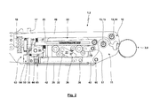
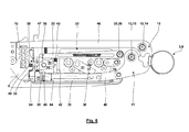
- the Fig. 1 to 6 show the relevant part of a pressing tool 1 in different operating positions during the pressing process and the return to a starting position.
- the pressing tool 1 is shown in exploded view.
- the pressing tool 1 is a manually operated pressing tongs 2.
- the crimping tool 2 is used for crimping and plastically deforming a (pipe) clamp 3, for example, to connect two radially inwardly arranged from this components frictionally and / or positively and mechanically permanently with each other and / or seal against each other. It is possible that the clamp 3 is used for attaching an axle cuff on a shaft.
- the pressing tongs 2 is manually operated by hand lever 4, 5, wherein in the in Fig. 1 to 6 shown section of the pressing tongs 2 only the hand lever 4 can be seen.
- the hand lever 4 is pivotally mounted about a bearing pin 6 formed by a pivot bearing 7 relative to a housing 8 or pliers head.
- the hand lever 5 is rigidly connected to the housing 8.
- the pressing of a workpiece 9, here the clamp 3 with further components arranged therein, takes place between two pressing jaws 10, 11, which are spaced apart from each other, formed by bearing pins 12, 13 pivot bearing 14, 15th from the starting position according to Fig. 1 are pivotable in a closed position and back to the starting position.
- the bearing pins 12, 13 are fixed relative to the housing 8.
- the hand lever 4 is L-shaped, wherein in the free end region of the much longer leg, the manual operation is performed by the user.
- the pivot bearing 7 is arranged in the connecting region of the two legs of the L.
- the free end portion of the shorter leg of the L carries a bearing pin 17, which is pivoted about the pivot bearing 7 with the hand lever 4.
- the bearing pin 17 forms a pivot bearing 18 for an end region of a pull tab 19.
- a pivot bearing 21 is formed with a bearing pin 20, via which the pull tab 19 is hinged to a feed unit 22.
- the feed unit 22 has a guide 23, which is designed here as a pivot bar and in Fig. 1 on the bottom has a sliding or guide surface 24.
- the guide 23 is supported via a bearing pin 25 to form a pivot bearing 26 pivotally relative to the housing.
- a spring 27 the guide 23 in Fig. 1 counteracted about the pivot bearing 26 counterclockwise.
- a housing 28 of the feed unit 22 is guided on the guide surface 24 of the guide 23 via rollers 29, 30.
- the feed unit 22 has a feed lever 31, which by means of a bearing pin 32 with the formation of a pivot bearing 33 relative to the housing 28 of the feed unit 22 is pivotable.
- the feed lever 31 is in this case in Fig. 1 clockwise acted upon by a spring 34.
- a feed rod 35 Opposite the housing 8 is in Fig. 1 slidably guided in the horizontal direction, a feed rod 35.
- the feed lever 31 and the feed rod 35 are interacting with locking teeth 36, 37, wherein the locking teeth 36 of the feed lever 31 is formed in the region of the abutting on the feed rod 35 end face, while the locking teeth 37 of the feed rod 35 in the contact area on the top of the same is.
- the locking teeth 36. 37 are pressed together by the spring 34 and the spring 27.
- the locking teeth 36, 37 are formed such that at pressure forces in the feed lever 31 as a result of movement of the feed unit 22 in Fig.
- a thrust pocket 40 which is hinged in the end of the feed rod 35 end portion via a bearing pin 60 on the pressing jaw 11.
- the effective direction of the push rod 40 which results from the connecting axis of the bearing bolt formed with the pivot bearing 61 and the pivot bearing 39 extends eccentrically to the pivot bearing 14 of the pressing jaw 11, so that a thrust force in the push rod 40 applies a closing moment on the pressing jaw 11.
- the feed rod 35 has a further toothing 41, in which a locking element 42 engages with a tooth or a toothing.
- the blocking element 42 is guided vertically to the guide direction of the feed rod 35 and acted upon by a spring 43 in the direction of the toothing 41 of the feed rod 35.
- the feed rod 35 is in Fig. 1 via a spring 44, in particular a tension spring, acted upon by the pressing jaw 11 away.
- the feed rod 35 can be in Fig. 1 in the direction of the press jaw 11 ratchet-like move relative to the locking element 42, while for movement of the feed rod 35 in the opposite direction due to the positive engagement of the locking element 42 in the teeth 41, the movement of the feed rod 35 is blocked.
- a Zwangsgesperre 45 is formed.
- the teeth 36, 37 on the one hand and the Zwangsgesperre 35 thus block a movement of the feed rod 35 in mutually opposite directions.
- the pressing jaw 10 is (integrally formed for the illustrated embodiment) of a cranked or L-shaped lever 46 in the region of the much shorter leg of the L, wherein the pivot bearing 14 in the region of the crank or the connecting portion the leg of the L is arranged.
- the spring 16 In the press jaw 10 facing away from the end portion of the lever 46 is supported by the spring 16 on the housing 8, which can be done without or with bias of the spring 16.
- With increasing pressing force on the pressing jaw 10 (and for prestressed spring 16 only when exceeding a predetermined by the bias threshold force) pivots the lever 46 in Fig. 1 counterclockwise about the pivot bearing 14 relative to the housing 8, which corresponds to an opening movement of the pressing jaw 10.
- this opening movement of the pressing jaw 10 is smaller or much smaller than the corresponding closing movement of the other pressing jaw eleventh
- the lever 46 carries, in particular adjacent to the end region, which interacts with the spring 16, an adjusting screw 47 or a Einstellpin which or which is oriented tangentially to the pivot axis of the pivot bearing 14.
- An actuation and display unit 49 is pressed against the front of the adjusting screw 47 arranged inside the pressing tongs 2 via a spring 48 supported on the housing 8.
- the actuation and display unit 49 is L-shaped with a shorter leg 50 which abuts the end face of the adjusting screw 47, and a longer leg 51 which has a bore in the region of which a guide parallel to the adjusting screw 47 is carried by a housing 8 carried by the guide rod formed.
- an activating element 54 is rotatably mounted relative to the housing 8 by means of a pivot bearing 53 formed with a bearing pin 52.
- the activation element 54 has approximately in a 3 o'clock position via a projection 55 and in a 12 o'clock position via a projection 56.
- the projection 55 engages in the in Fig. 1
- the guide 23 is supported in such a way that the projection 56 obstructs a pivoting of the guide 23 of the feed rod 35 away.
- a spring 66 acts on the activation element 54 in Fig. 1 in the clockwise direction and in the direction of the explained blocking a movement of the guide 23, which is oriented away from the feed rod 35.
- FIG. 2 shows the end position of the hand lever 4 with completion of the first pressing stage, for which the hand lever 4 is oriented parallel to the hand lever 5, wherein Fig. 2 the hand lever 4 is covered by the other components.
- the hand lever 4 is then pivoted back away from the user of the hand lever 5, until the in Fig. 3 shown position of the hand lever 4 is reached.
- ratchet-like sliding of the feed lever 31 with its locking teeth 36 via the locking teeth 37 of the feed rod 35 so that the feed unit 22 can be moved back to the left and away from the pressing jaw 11 without the feed rod 35 is taken.
- the reached at the end of the first pressing stage position of the feed rod 35 is hereby secured by the Zwangsgesperre 45.
- the tooth spacing of the toothing 41 of the forced locking mechanism 45 corresponds to the extent of movement of the feed rod 35, which can be brought about with the stroke of the hand lever 4 in the first pressing stage.
- a blocking element 64 (shown in phantom in the figures) is pushed under the guide 23, which the Guide 23 (and thus the feed unit 22) at a distance from the feed rod 35 holds, so that the locking teeth 36, 37 do not interact with each other ( Fig. 5 ).
- the blocking element 64 is displaceably guided relative to the housing 8 and supported by a spring, not shown here so that the blocking element 64 is acted upon in the direction of the feed unit 22. The movement of the feed rod 35 of the pressing jaw 11 away is caused by the spring 44.
- a pressing force limiting means 63 is formed. This is activated at the moment in which the guide 23 fixing effect of the projection 56 is removed and the locking teeth 36, 37 are disengaged and the locking element 42 is lifted out of the toothing 41. With this activation, no further increase in a pressing force can take place - on the contrary, the pressing tongs 2 automatically return (at least partially) to the initial position Fig. 1 with open pressing jaws 10, 11 back.
- the spring stiffness of the spring 16 and the lever ratios to the lever 46 can be specified for which pressing force the pressing force limiting device 63 is activated.
- This maximum pressing force which is also referred to as desired pressing force, can thus be adjusted by changing the screwing of the adjusting screw 47, whereby the game 59 increases or decreases.
- the actuating and display unit 49 moves.
- This can have a pointer, not shown in the figures, which is visible from the outside of the pressing tongs 2. It is possible that in the area of the pointer, the housing 8 has a scale.
- the pointer moves along the scale, whereby the size of the game 59 and thus the size of the target pressing force for which the pressing force limiting device 63 is activated, is visible from the outside and also a setting process of the adjusting screw 47 can be visually monitored by the operator.
- a return device 65 which automatically moves the pressing tool at least partially back to an initial position upon reaching the predetermined pressing force, is formed with the spring 44. If a temporary blockage of the return movement of the feed unit 22 is required, the return device 65 is also formed with the blocking element 64 and the associated spring.
Abstract
Die Erfindung betrifft ein Presswerkzeug (1), welches vorzugsweise als Presszange ausgebildet ist. Erfindungsgemäß besitzt das Presswerkzeug eine mechanische Presskraft-Begrenzungs-einrichtung (63). Die Presskraft-Begrenzungseinrichtung (63) begrenzt die mit dem Presswerkzeug (1) herbeiführbare Presskraft unabhängig von einer Größe eines Presshubs auf eine vorgegebene Soll-Presskraft. Das erfindungsgemäße Presswerkzeug findet insbesondere Einsatz für Schellen (3), welche mittels plastischer Verformung montiert werden.The invention relates to a pressing tool (1), which is preferably designed as pressing tongs. According to the invention, the pressing tool has a mechanical pressing force limiting device (63). The pressing force limiting device (63) restricts the pressing force which can be brought about with the pressing tool (1) to a predetermined set pressing force independently of a magnitude of a pressing stroke. The pressing tool according to the invention finds particular use for clamps (3), which are mounted by means of plastic deformation.
Description
Die Erfindung betrifft ein Presswerkzeug zum Verpressen eines Werkstücks. Beispielsweise kann das Verpressen des Werkstücks zum reibschlüssigen oder dichten Verbinden von Bauelementen, insbesondere eines Stutzens mit einer Leitung oder einem Schlauch, einer Manschette mit einer Welle o. ä. (unter Umständen über eine plastisch verpresste Schelle), Einsatz finden, wobei beim Verpressen des Werkstücks eine plastische Verformung desselben erfolgen kann. Des Weiteren betrifft die Erfindung eine manuell betätigte Presszange sowie eine neue Verwendung eines besonderen Presswerkzeugs oder einer Presszange.The invention relates to a pressing tool for pressing a workpiece. For example, the pressing of the workpiece for frictional or tight connection of components, in particular a nozzle with a pipe or a hose, a sleeve with a shaft o. Ä. (Under some circumstances, a plastically pressed clamp), use, wherein during compression of the Workpiece a plastic deformation of the same can take place. Furthermore, the invention relates to a manually operated pressing tongs and a new use of a special pressing tool or a pressing tongs.
Bei dem Presswerkzeug kann es sich um ein beliebiges Werkzeug handeln, mittels dessen ein Vepressen oder "Crimpen" eines beliebigen Werkstücks erfolgt. Ein beispielhafter möglicher Anwendungsbereich der Erfindung ist eine Presszange, die für Schlauchklemmen eines besonderen Typs eingesetzt wird. Bekannt sind Schlauchklemmen, bei welchen die Klemmkraft über einen über eine Schneckenschraube betätigten Schneckentrieb erzeugt wird, wobei das Anzugsmoment der Schneckenschraube die Klemmkraft vorgibt. Abweichend kann für den besonderen Typ von Schlauchklemmen die Klemmkraft nicht durch einen derartigen Schneckentrieb, sondern mittels einer durch eine erfindungsgemäße Presszange erzeugten plastischen Verformung herbeigeführt werden. Einsatz findet dieser Typ von Schlauchklemmen bspw. im Automotive-Bereich, beispielsweise für eine Fixierung einer Achsmanschette auf einer Achswelle über eine plastisch verformte Schlauchklemme. Die Klemmkraft bestimmt hierbei eine Dichtkraft zwischen der Manschette und der Achswelle und eine Haltekraft oder Fixierkraft. Ein weiterer Anwendungsbereich derartiger Schlauchklemmen ist beispielsweise die "weiße Ware" mit sämtlichen Produkten, bei welchen ein Schlauch auf einen Stutzen unter Erzeugung einer Dichtwirkung aufgeklemmt werden muss.The pressing tool can be any tool by means of which a pressing or "crimping" of any workpiece takes place. An exemplary possible application of the invention is a crimping pliers used for hose clamps of a particular type. Hose clamps are known in which the clamping force is generated via a worm drive actuated by means of a worm screw, the tightening torque of the worm screw predetermining the clamping force. By way of derogation, the clamping force for the particular type of hose clamps can not be brought about by such a worm drive but by means of a plastic deformation produced by a pressing tongs according to the invention. This type of hose clamps is used, for example, in the automotive sector, for example for fixing an axle collar on an axle shaft via a plastically deformed hose clamp. The clamping force in this case determines a sealing force between the sleeve and the axle shaft and a holding force or fixing force. Another field of application of such hose clamps is, for example, the "white goods" with all products in which a hose must be clamped onto a nozzle to produce a sealing effect.
Üblicherweise wird die maximale Presskraft beim Verpressen eines Werkstücks mittels eines Presswerkzeugs durch die applizierte Betätigungskraft, beispielsweise manuell auf Handhebel einer Presszange aufgebrachte Handkräfte oder die Kraft eines Aktuators bei einer Pressmaschine, vorgegeben. Das Ausmaß des Verpressens eines Werkstücks mittels einer manuell betätigten Presszange ist somit abhängig von den Fertigkeiten und einer reproduzierbaren, feinfühligen Betätigung des Benutzers über dessen Hände. Hingegen bedarf das reproduzierbare Verpressen eines Werkstücks mit vorgegebener Soll-Presskraft mittels eines Aktuators einer Pressmaschine des Einsatzes von Sensoren zur Erfassung der Presskraft während des Presshubs und/oder einer Steuerung oder Regelung der Betätigung durch den Aktuator.Usually, the maximum pressing force during pressing of a workpiece by means of a pressing tool by the applied operating force, for example, manually applied to the hand lever of a pressing tongs applied hand forces or the force of an actuator in a pressing machine. The extent of pressing a workpiece by means of a manually operated pressing tongs is thus dependent on the skills and a reproducible, sensitive operation of the user on the hands. By contrast, the reproducible pressing of a workpiece with a predetermined set pressing force by means of an actuator of a pressing machine requires the use of sensors for detecting the pressing force during the pressing stroke and / or a control or regulation of the actuation by the actuator.
Der vorliegenden Erfindung liegt die Aufgabe zugrunde, ein Presswerkzeug oder eine Presszange zum Verpressen eines Werkstücks dahingehend zu optimieren, dass am Ende des Presshubs definierte Pressbedingungen vorliegen, womit die Prozesssicherheit erhöht werden kann.The object of the present invention is to optimize a pressing tool or a pressing tongs for pressing a workpiece in such a way that defined pressing conditions are present at the end of the pressing stroke, whereby the process reliability can be increased.
Die Aufgabe der Erfindung wird erfindungsgemäß mit den Merkmalen der unabhängigen Patentansprüche gelöst. Weitere bevorzugte erfindungsgemäße Ausgestaltungen sind den abhängigen Patentansprüchen zu entnehmen.The object of the invention is achieved with the features of the independent claims. Further preferred embodiments according to the invention can be found in the dependent claims.
Die Erfindung schlägt ein Presswerkzeug vor, mittels welchem unabhängig von etwaigen Fertigungstoleranzen oder Imperfektionen des Werkstücks und Ungenauigkeiten bei dem Kontakt des Werkstücks mit dem Presswerkzeug oder bei einem Einlegen des Werkstücks in das Werkzeug oder auch unabhängig von der Größe und des Typs des Werkstücks und damit von der Größe eines Presshubs am Ende des Presshubs eine Presskraft herbeigeführt wird, welche möglichst exakt einer vorgegebenen Soll-Presskraft entspricht. Dies hat beispielsweise die folgenden Vorteile:
- Handelt es sich bei dem zu verpressenden Werkstück um ein Kontaktelement, beispielsweise eine Verbindung zwischen einem Stecker und einem Leiter, führt die vorgegebene Soll-Presskraft am Ende des Pressvorgangs zu der Gewährleistung der gewünschten Kontaktierung, wobei auch Beschädigungen von Stecker oder Leiter infolge von zu großen Presskräften vermieden sein können. Andererseits kann eine definierte mechanische Verbindung zwischen Stecker und Leiter herbeigeführt werden, wodurch beispielsweise vermieden werden kann, dass sich im Betrieb des Werkstücks nach Beendigung des Pressvorgangs der Stecker von dem Leiter löst.
- Bei einem Werkstück in Form einer Verbindung von Schläuchen, Stutzen, Steckern, Anschlüssen und/oder Schellen führt die definierte Soll-Presskraft am Ende des Pressvorgangs dazu, dass eine zuverlässige mechanische Verbindung geschaffen ist. Soll die mechanische Verbindung gleichzeitig die Dichtigkeit gewährleisten, trägt die definierte Soll-Presskraft am Ende des Pressvorgangs auch zu einer hohen Zuverlässigkeit der Abdichtung bei.
- If the workpiece to be compacted is a contact element, for example a connection between a plug and a conductor, the predetermined desired pressing force at the end of the pressing operation leads to ensuring the desired contacting, whereby damage to the plug or conductor as a result of too large pressing forces can be avoided. On the other hand, a defined mechanical connection between plug and conductor can be brought about, for example, whereby it can be avoided that the plug is released from the conductor during operation of the workpiece after completion of the pressing operation.
- In the case of a workpiece in the form of a connection of hoses, nozzles, plugs, connections and / or clamps, the defined nominal pressing force at the end of the pressing operation results in a reliable mechanical connection being created. If the mechanical connection at the same time to ensure the tightness, the defined target pressing force at the end of the pressing process also contributes to a high reliability of the seal.
Erfindungsgemäß findet eine Presskraft-Begrenzungseinrichtung in dem Presswerkzeug Einsatz. Diese ist (abweichend zu
Wird in die Presszange gemäß
Durchaus möglich ist, dass mit Beendigung des Pressvorgangs und der Begrenzung der Presskraft durch die mechanische Presskraft-Begrenzungseinrichtung durch eine Steuerung, einen Aktuator oder den Benutzer weitere Schritte einzuleiten sind, um das Presswerkzeug wieder in die Ausgangsstellung zu bewegen, bei welcher es sich beispielsweise um eine Stellung mit geöffneten Pressbacken handeln kann. Für einen besonderen Vorschlag der Erfindung verfügt das Presswerkzeug über eine Rückstelleinrichtung. Die Rückstelleinrichtung bewegt mit Erreichen des vorgegebenen Schwellwerts (und Aktivierung der Presskraft-Begrenzungseinrichtung) automatisch das Presswerkzeug wieder in eine Ausgangsstellung zurück. Während grundsätzlich beliebige Ausgestaltungen der Rückstelleinrichtung möglich sind, handelt es sich hierbei vorzugsweise um eine mechanische Rückstelleinrichtung, welche beispielsweise eine in einer Feder während des Presshubs gespeicherte Energie nutzen kann. Für ein Presswerkzeug in dieser Ausgestaltung ergibt sich unter Umständen eine besonders einfache Handhabung oder Betätigung, für welche nach Beendigung des Presshubs und Aktivierung der Presskraft-Begrenzungseinrichtung automatisiert eine Bewegung in die Ausgangsstellung erfolgt, womit dann auch eine Entnahme des Werkstücks aus dem Presswerkzeug erfolgen kann.It is entirely possible that with the completion of the pressing process and the limitation of the pressing force by the mechanical pressing force limiting device by a controller, an actuator or the user to initiate further steps to move the pressing tool back to the starting position, which for example at a position with open pressing jaws can act. For a particular proposal of the invention, the pressing tool has a return device. The return device automatically moves the pressing tool back to an initial position upon reaching the predetermined threshold value (and activation of the pressing force limiting device). While basically any embodiments of the restoring device are possible, this is preferably a mechanical restoring device, which can use, for example, an energy stored in a spring during the pressing stroke. For a pressing tool in this embodiment, under certain circumstances results in a particularly simple handling or actuation, for which after completion of the press stroke and activation of the pressing force limiting device automatically moves to the starting position, which then can take place a removal of the workpiece from the pressing tool.
Möglich ist, dass das Presswerkzeug über eine fest vorgegebene Soll-Presskraft verfügt. In weiterer Ausgestaltung der Erfindung ist die Soll-Presskraft einstellbar. Hierdurch kann eine Feinjustage des Arbeitsbereichs des Presswerkzeugs erfolgen. Ebenfalls möglich ist, dass durch die Einstellbarkeit der vorgegebenen Soll-Presskraft das Presswerkzeug multifunktional gestaltet wird, indem dieses zum Verpressen unterschiedlicher Werkstücke, welche unterschiedliche vorgegebene Soll-Presskräfte erfordern, (u. U. auch mit dem Einsatz unterschiedlicher an dem Werkzeug gehaltener Gesenke) verwendet werden kann.It is possible that the pressing tool has a fixed predetermined desired pressing force. In a further embodiment of the invention, the desired pressing force is adjustable. This allows a fine adjustment of the working range of the pressing tool done. It is also possible that the pressing tool is made multifunctional by the adjustability of the predetermined desired pressing force, by this for pressing different workpieces, which require different predetermined set pressing forces, (possibly also with the use of different dies held on the tool) can be used.
Für die konkrete Ausgestaltung der mechanischen Presskraft-Begrenzungseinrichtung gibt es vielfältige Möglichkeiten, welche nicht auf die in der vorliegenden Patentanmeldung offenbarten Ausgestaltungsformen begrenzt sind. Für eine erfindungsgemäße Ausgestaltung verfügt hierbei das Presswerkzeug über eine Pressbacke, welche über eine Feder abgestützt ist. Während des Presshubs kann somit die Pressbacke unter Beaufschlagung der Feder bewegt werden oder in Pressrichtung "nachgeben". In diesem Fall wird die Presskraft-Begrenzungseinrichtung durch die über die Feder abgestützte Pressbacke (oder ein mit dieser bewegtes Bauelement) bewegungsgesteuert aktiviert. Umfasst sind hierbei Ausgestaltungsformen, bei welcher die Pressbacke unmittelbar oder mittelbar unter Verwendung weiterer, mit der Pressbacke bewegter Bauelemente, über die Feder abgestützt ist. Möglich ist hierbei
- die Abstützung der Pressbacke über eine nicht vorgespannte Feder, so dass sich mit Erhöhung der Presskraft kontinuierlich die Pressbacke unter Beaufschlagung der Feder bewegen kann, oder
- die Abstützung der Pressbacke an der Feder mit Vorspannung derselben, womit sich die Pressbacke mit Erhöhung der Presskraft erst bewegt, wenn die Vorspannkraft der Feder überwunden ist.
- the support of the pressing jaw over a non-preloaded spring, so that can move continuously with increasing the pressing force, the pressing jaw under the action of the spring, or
- the support of the pressing jaw on the spring with bias thereof, whereby the pressing jaw moves with increasing the pressing force only when the biasing force of the spring is overcome.
In weiterer Ausgestaltung der Erfindung erfolgt die Einstellung der Soll-Presskraft über die Einstellung eines Spiels. Die Größe des Spiels ist während des Pressvorgangs von der Bewegung der Pressbacke oder eines mit der Pressbacke bewegten Bauelements abhängig. Die Aktivierung der Presskraft-Begrenzungseinrichtung erfolgt mit vollständigem Schließen des Spiels, womit eine Aktivierungs-Verbindung, ein mechanischer Kontakt o. ä. geschaffen ist, welcher die Aktivierung der Presskraft-Begrenzungseinrichtung zur Folge hat. Um lediglich ein Beispiel zu nennen, kann der Kontakt oder die Aktivierungs-Verbindung Kontaktkräfte erzeugen, welche ein Lösen eines Zwangsgesperres und/oder eine Rückbewegung des Presswerkzeugs in eine Ausgangsstellung bewirken.In a further embodiment of the invention, the setting of the desired pressing force on the setting of a game. The size of the game is dependent on the movement of the pressing jaw or a component moved with the pressing jaw during the pressing process. The activation of the pressing force limiting device takes place with complete closing of the game, whereby an activation connection, a mechanical contact o. Ä. Is created, which has the activation of the pressing force-limiting device result. To name just one example, the contact or the activation connection can generate contact forces, which cause a release of a Zwangsgesperres and / or a return movement of the pressing tool in a starting position.
In weiterer Ausgestaltung der Erfindung ist in dem Presswerkzeug eine Antriebsverbindung vorhanden. Diese Antriebsverbindung kann durch Aktivieren der Presskraft-Begrenzungseinrichtung gelöst werden, so dass kein weiterer Antrieb mehr möglich ist und somit keine weitere Erhöhung der Presskraft über die Soll-Presskraft hinaus möglich ist. Ebenfalls möglich ist, dass durch Aktivieren der Presskraft-Begrenzungseinrichtung die Antriebsverbindung blockiert wird.In a further embodiment of the invention, a drive connection is present in the pressing tool. This drive connection can be achieved by activating the pressing force limiting device, so that no further drive is possible and thus no further increase in the pressing force beyond the set pressing force is possible. It is also possible that by activating the pressing force limiting device, the drive connection is blocked.
In weiterer Ausgestaltung der Erfindung ist die über die Feder abgestützte Pressbacke oder ein mit dieser bewegtes Bauelement mit einer Anzeigeeinheit ausgestattet. Die Anzeigeeinheit ist von außen sichtbar. Mittels der Anzeigeeinheit kann das Ausmaß der Bewegung der über die Feder abgestützten Pressbacke und damit der Presskraft angezeigt werden, womit eine weitere Erhöhung der Prozesssicherheit erfolgen kann und dem Benutzer ergänzende Überwachungsmöglichkeiten zur Verfügung gestellt werden. Die Anzeigeeinheit ist vorzugsweise mechanisch ausgebildet, wobei ein Anzeigeelement mechanisch mit der federnd abgestützten Pressbacke gekoppelt sein kann.In a further embodiment of the invention, the supported via the spring pressing jaw or a moving with this device is equipped with a display unit. The display unit is visible from the outside. By means of the display unit, the extent of the movement of the supported via the spring pressing jaw and thus the pressing force can be displayed, whereby a further increase in process reliability can be done and the user additional monitoring options are provided. The display unit is preferably formed mechanically, wherein a display element can be mechanically coupled to the resiliently supported pressing jaw.
Für einen besonderen Vorschlag der Erfindung ist die Anzeigeeinheit multifunktional ausgebildet, indem diese nicht nur die Presskraft anzeigt, sondern auch der Einstellung der vorgegebenen Soll-Presskraft und der Anzeige der eingestellten vorgegebenen Soll-Presskraft dient. Hierbei ist es von Vorteil, wenn die Anzeigeinheit mit einem Bauelement gekoppelt oder verbunden ist, welches sowohl mit der Bewegung der Pressbacke mit Erhöhung der Presskraft bewegt wird als auch im Zuge der Einstellung der Soll-Presskraft bewegt wird.For a particular proposal of the invention, the display unit is multifunctional in that it not only displays the pressing force, but also serves to adjust the predetermined target pressing force and the display of the set predetermined set pressing force. It is advantageous if the display unit is coupled or connected to a component which is moved both with the movement of the pressing jaw with increasing the pressing force and is moved in the course of setting the target pressing force.
Das vorliegende Presswerkzeug kann einen beliebigen Antriebsmechanismus, beispielsweise einen scherenartigen Antrieb, einen Antrieb gemäß
In weiterer Ausgestaltung der Erfindung ist ein Zwangsgesperre vorhanden, welches eine Rückkehr in die Ausgangsstellung des Presswerkzeugs nur dann ermöglicht, wenn die Presskraft-Begrenzungseinrichtung aktiviert wird oder eine vorgegebene oder eingestellte Bewegung der über die Feder abgestützten Pressbacke erfolgt ist. Somit gewährleistet das Zwangsgesperre, dass eine einmal erreichte Pressstellung auch aufrechterhalten bleibt, wenn eine Betätigungskraft zumindest temporär beseitigt wird. Fehlbetätigungen, bei welchen der Presshub nicht so weit durchlaufen ist, dass die Presskraft-Begrenzungseinrichtung aktiviert worden ist, können durch Einsatz des Zwangsgesperres vermieden werden.In a further embodiment of the invention, a Zwangsgesperre is present, which only allows a return to the starting position of the pressing tool when the pressing force limiting device is activated or a predetermined or set movement of the supported via the spring pressing jaw is done. Thus, the Zwangsgesperre ensures that a once achieved press position is maintained even if a Actuating force is at least temporarily eliminated. Faulty operations in which the pressing stroke has not gone so far that the pressing force-limiting device has been activated, can be avoided by using the Zwangsgesperres.
Grundsätzlich möglich ist, dass das Zwangsgesperre nach oder zu dem Zeitpunkt entsperrt wird, an dem die Presskraft-Begrenzungseinrichtung aktiviert wird. In bevorzugter Ausgestaltung der Erfindung erfolgt aber die Entsperrung des Zwangsgesperres bevor die Presskraft-Begrenzungseinrichtung aktiviert wird.In principle, it is possible that the Zwangsgesperre is unlocked after or at the time at which the pressing force limiting device is activated. In a preferred embodiment of the invention, however, the unlocking of Zwangsgesperres before the press force limiting device is activated.
Wie zuvor erwähnt, kann es sich bei dem erfindungsgemäßen Presswerkzeug um ein Presswerkzeug beliebiger Ausgestaltung handeln. Auch für eine Ausgestaltung des Presswerkzeugs als Pressmaschine mit einem elektrischen, pneumatischen oder hydraulischen Aktuator kann vorteilhaft die mechanische Presskraft-Begrenzungseinrichtung eingesetzt werden. Für eine Lösung der der Erfindung zugrunde liegenden Aufgabe wird aber eine manuell betätigte Presszange als Presswerkzeug, wie dieses zuvor beschrieben worden ist, ausgebildet. In dieser Presszange gewährleistet die Presskraft-Begrenzungseinrichtung, dass unabhängig von der Bedienung durch den Benutzer und unabhängig von den von den Benutzern aufgebrachten Handkräften die Presskraft nicht größer werden kann als die Soll-Presskraft.As mentioned above, the pressing tool according to the invention may be a pressing tool of any desired configuration. Also for an embodiment of the pressing tool as a pressing machine with an electric, pneumatic or hydraulic actuator may advantageously be used, the mechanical pressing force limiting device. For a solution to the problem underlying the invention but a manually operated pressing tongs as a pressing tool, as has been previously described, formed. In this pressing tongs, the pressing force limiting means ensures that the pressing force can not become larger than the target pressing force, regardless of the operation by the user and the manual force applied by the users.
Das erfindungsgemäße Presswerkzeug oder die manuell betätigte Presszange können für das Verpressen beliebiger Werkstücke verwendet werden. Für einen weiteren Vorschlag der Erfindung findet ein Presswerk der zuvor erläuterten Art oder eine manuell betätigte Presszange der zuvor erläuterten Art Verwendung für ein Verpressen einer (Rohr-)Schelle, welche mit einem plastischen Verpressen der Schelle montiert wird, beispielsweise indem die Schelle auf einen Schlauch oder eine Rohrleitung aufgepresst wird, welche wiederum gegen die Mantelfläche eines im Inneren angeordneten Stutzens, eines Rohrendes oder einer Welle o. ä. aufgepresst werden soll. Vorzugsweise ist die Presszange als sogenannte Ohrschellenklemme ausgebildet.The pressing tool according to the invention or the manually operated pressing tongs can be used for the compression of any workpieces. For a further proposal of the invention finds a press shop of the type described above or a manually operated pressing tongs of the type described above use for pressing a (pipe) clamp, which is mounted with a plastic pressing the clamp, for example by the clamp on a hose or a pipe is pressed, which in turn is to be pressed against the outer surface of a nozzle arranged in the interior, a pipe end or a shaft o. Ä. Preferably, the crimping tool is designed as a so-called ear clamp.
Vorteilhafte Weiterbildungen der Erfindung ergeben sich aus den Patentansprüchen, der Beschreibung und den Zeichnungen. Die in der Beschreibung genannten Vorteile von Merkmalen und von Kombinationen mehrerer Merkmale sind lediglich beispielhaft und können alternativ oder kumulativ zur Wirkung kommen, ohne dass die Vorteile zwingend von erfindungsgemäßen Ausführungsformen erzielt werden müssen. Ohne dass hierdurch der Gegenstand der beigefügten Patentansprüche verändert wird, gilt hinsichtlich des Offenbarungsgehalts der ursprünglichen Anmeldungsunterlagen und des Patents Folgendes: weitere Merkmale sind den Zeichnungen - insbesondere den dargestellten Geometrien und den relativen Abmessungen mehrerer Bauteile zueinander sowie deren relativer Anordnung und Wirkverbindung - zu entnehmen. Die Kombination von Merkmalen unterschiedlicher Ausführungsformen der Erfindung oder von Merkmalen unterschiedlicher Patentansprüche ist ebenfalls abweichend von den gewählten Rückbeziehungen der Patentansprüche möglich und wird hiermit angeregt. Dies betrifft auch solche Merkmale, die in separaten Zeichnungen dargestellt sind oder bei deren Beschreibung genannt werden. Diese Merkmale können auch mit Merkmalen unterschiedlicher Patentansprüche kombiniert werden. Ebenso können in den Patentansprüchen aufgeführte Merkmale für weitere Ausführungsformen der Erfindung entfallen.Advantageous developments of the invention will become apparent from the claims, the description and the drawings. The advantages of features and of combinations of several features mentioned in the description are merely exemplary and can take effect alternatively or cumulatively, without the advantages having to be achieved by embodiments according to the invention. Without thereby the subject of attached As regards the disclosure content of the original application documents and the patent, the following applies: Further features can be taken from the drawings-in particular the illustrated geometries and the relative dimensions of several components relative to one another and their relative arrangement and operative connection. The combination of features of different embodiments of the invention or of features of different claims is also possible deviating from the chosen relationships of the claims and is hereby stimulated. This also applies to those features which are shown in separate drawings or are mentioned in their description. These features can also be combined with features of different claims. Likewise, in the claims listed features for further embodiments of the invention can be omitted.
Die in den Patentansprüchen und der Beschreibung genannten Merkmale sind bezüglich ihrer Anzahl so zu verstehen, dass genau diese Anzahl oder eine größere Anzahl als die genannte Anzahl vorhanden ist, ohne dass es einer expliziten Verwendung des Adverbs "mindestens" bedarf. Wenn also beispielsweise von einem Element die Rede ist, ist dies so zu verstehen, dass genau ein Element, zwei Elemente oder mehr Elemente vorhanden sind. Diese Merkmale können durch andere Merkmale ergänzt werden oder die einzigen Merkmale sein, aus denen das jeweilige Erzeugnis besteht.The features mentioned in the patent claims and the description are to be understood in terms of their number that exactly this number or a greater number than the said number is present, without requiring an explicit use of the adverb "at least". For example, when talking about an element, it should be understood that there is exactly one element, two elements or more elements. These features may be supplemented by other features or be the only characteristics that make up the product in question.
Im Folgenden wird die Erfindung anhand in den Figuren dargestellter bevorzugter Ausführungsbeispiele weiter erläutert und beschrieben.
- Fig. 1
- zeigt einen relevanten Teil eines Presswerkzeugs in einer geschnittenen Seitenansicht.
- Fig. 2
- zeigt das Presswerkzeug gemäß
Fig. 1 am Ende einer ersten Pressstufe. - Fig. 3
- zeigt das Presswerkzeug gemäß
Fig. 1 und2 zu Beginn einer zweiten Pressstufe.
- Fig. 4
- zeigt das Presswerkzeug gemäß
Fig. 1 bis 3 zum Zeitpunkt des Aktivierens der Presskraft-Begrenzungseinrichtung. - Fig. 5
- zeigt die automatische Rückstellung des Presswerkzeugs gemäß
Fig. 1 in Richtung der Ausgangsstellung nach Aktivieren der Presskraft-Begrenzungseinrichtung, wobei ein Sperrelement eine Führung in einer gelösten Stellung hält.bis 4 - Fig. 6
- zeigt das Presswerkzeug gemäß
Fig. 1 bis 5 nach Aktivieren der PresskraftBegrenzungseinrichtung, wobei die Führung von dem Sperrelement wieder freigegeben worden ist und eine Vorschubeinheit als Bestandteil des Antriebsmechanismus wieder in Eingriff gebracht worden ist. - Fig. 7
- zeigt das Presswerkzeug gemäß
Fig. 1 bis 6 in einer Explosionsdarstellung.
- Fig. 1
- shows a relevant part of a pressing tool in a sectional side view.
- Fig. 2
- shows the pressing tool according to
Fig. 1 at the end of a first pressing stage. - Fig. 3
- shows the pressing tool according to
Fig. 1 and2 at the beginning of a second pressing stage.
- Fig. 4
- shows the pressing tool according to
Fig. 1 to 3 at the time of activating the pressing force limiting means. - Fig. 5
- shows the automatic recovery of the pressing tool according to
Fig. 1 to 4 in the direction of the initial position after activating the pressing force limiting device, wherein a blocking element holds a guide in a released position. - Fig. 6
- shows the pressing tool according to
Fig. 1 to 5 after activating the pressing force limiting device, wherein the guide has been released from the locking element and a feed unit has been re-engaged as part of the drive mechanism. - Fig. 7
- shows the pressing tool according to
Fig. 1 to 6 in an exploded view.
Die
Die Presszange 2 findet Einsatz zum Verpressen und plastischen Verformen einer (Rohr-)Schelle 3, beispielsweise um zwei radial innenliegend von dieser angeordnete Bauelemente reibschlüssig und/oder formschlüssig und mechanisch dauerhaft miteinander zu verbinden und/oder gegeneinander abzudichten. Möglich ist, dass die Schelle 3 Einsatz findet zur Befestigung einer Achsmanschette auf einer Welle.The crimping
Die Presszange 2 wird manuell über Handhebel 4, 5 betätigt, wobei in dem in
Der Handhebel 4 ist L-förmig ausgebildet, wobei in dem freien Endbereich des sehr viel längeren Schenkels die manuelle Betätigung durch den Benutzer erfolgt. Das Schwenklager 7 ist im Verbindungsbereich der beiden Schenkel des L angeordnet. Der freie Endbereich des kürzeren Schenkels des L trägt einen Lagerbolzen 17, der mit dem Handhebel 4 um das Schwenklager 7 verschwenkt wird. Der Lagerbolzen 17 bildet ein Schwenklager 18 für einen Endbereich einer Zuglasche 19. In dem anderen Endbereich der Zuglasche 19 ist mit einem Lagerbolzen 20 ein Schwenklager 21 gebildet, über welches die Zuglasche 19 an einer Vorschubeinheit 22 angelenkt ist.The
Die Vorschubeinheit 22 verfügt über eine Führung 23, welche hier als Schwenkbalken ausgebildet ist und in
Gegenüber dem Gehäuse 8 ist in
In dem der Pressbacke 11 zugewandten Endbereich der Vorschubstange 35 ist an dieser über ein mit einem Lagerbolzen 38 gebildetes Schwenklager 39 eine Schublasche 40 angelenkt, welche in dem der Vorschubstange 35 abgewandten Endbereich über einen Lagerbolzen 60 an der Pressbacke 11 angelenkt ist. Die Wirkrichtung der Schubstange 40, welche sich durch die Verbindungsachse des mit dem Lagerbolzen gebildeten Schenklagers 61 und des Schwenklagers 39 ergibt, verläuft exzentrisch zu dem Schwenklager 14 der Pressbacke 11, so dass eine Schubkraft in der Schubstange 40 ein Schließmoment auf die Pressbacke 11 aufbringt.In which the
Abseits der Rastverzahnung 37 verfügt die Vorschubstange 35 über eine weitere Verzahnung 41, in welche ein Sperrelement 42 mit einem Zahn oder einer Verzahnung eingreift. Das Sperrelement 42 ist vertikal zur Führungsrichtung der Vorschubstange 35 geführt und über eine Feder 43 in Richtung der Verzahnung 41 der Vorschubstange 35 beaufschlagt. Die Vorschubstange 35 wird in
Die Pressbacke 10 wird (für das dargestellte Ausführungsbeispiel einstückig) von einem gekröpften oder L-förmigen Hebel 46 im Bereich des sehr viel kürzeren Schenkels des L ausgebildet, wobei das Schwenklager 14 im Bereich der Kröpfung oder des Verbindungsbereichs der Schenkel des L angeordnet ist. In dem der Pressbacke 10 abgewandten Endbereich ist der Hebel 46 über die Feder 16 am Gehäuse 8 abgestützt, was ohne oder mit Vorspannung der Feder 16 erfolgen kann. Mit ansteigender Presskraft an der Pressbacke 10 (und für vorgespannte Feder 16 erst mit Überschreiten einer durch die Vorspannung vorgegebenen Schwellkraft) verschwenkt der Hebel 46 in
Der Hebel 46 trägt, insbesondere benachbart dem Endbereich, welcher mit der Feder 16 in Wechselwirkung steht, eine Einstellschraube 47 oder einen Einstellpin, welche oder welcher tangential zur Schwenkachse des Schwenklagers 14 orientiert ist. An die innerhalb der Presszange 2 angeordnete Stirnseite der Einstellschraube 47 wird über eine am Gehäuse 8 abgestützte Feder 48 eine Betätigungs- und Anzeigeeinheit 49 angepresst. Für das dargestellte Ausführungsbeispiel ist die Betätigungs- und Anzeigeeinheit 49 L-förmig mit einem kürzeren Schenkel 50, welcher an der Stirnseite der Einstellschraube 47 anliegt, und einem längeren Schenkel 51, welcher über eine Bohrung verfügt, im Bereich welcher eine Führung parallel zu der Einstellschraube 47 durch eine vom Gehäuse 8 getragene Führungsstange erfolgt, ausgebildet.The
Gegenüber dem Gehäuse 8 ist des Weiteren mittels eines mit einem Lagerbolzen 52 gebildeten Schwenklagers 53 ein Aktivierungselement 54 verdrehbar gelagert. Das Aktivierungselement 54 verfügt ungefähr in einer 3-Uhr-Position über einen Vorsprung 55 sowie in einer 12-Uhr-Position über einen Vorsprung 56. Der Vorsprung 55 greift in der in
Die Funktion der Presszange 2 wird im Folgenden anhand der unterschiedlichen Betriebsstellungen gemäß
In der Ausgangsstellung gemäß
Wird ausgehend von der Ausgangsstellung gemäß
Zu erkennen ist in
Um eine weitere Pressstufe zu ermöglichen, wird hieran anschließend der Handhebel 4 wieder vom Benutzer von dem Handhebel 5 weg verschwenkt, bis die in
Mit dem Hebel 46, der Feder 16, der Einstellschraube 47, der Betätigungs- und Anzeigeeinheit 49, dem Aktivierungselement 54 und dessen Wechselwirkung über den Vorsprung 55 mit dem Sperrelement 42, des Vorsprungs 56 mit der Führung 23 und des Fortsatzes 58 mit der Betätigungs- und Anzeigeeinheit 49 ist eine Presskraft-Begrenzungseinrichtung 63 gebildet. Diese wird aktiviert in dem Moment, in welchem die die Führung 23 fixierende Wirkung des Vorsprungs 56 beseitigt wird und die Rastverzahnungen 36, 37 außer Eingriff kommen sowie das Sperrelement 42 aus der Verzahnung 41 herausgehoben wird. Mit dieser Aktivierung kann keine weitere Erhöhung einer Presskraft erfolgen - vielmehr kehrt hiermit automatisch die Presszange 2 wieder (zumindest teilweise) in die Ausgangslage gemäß
Über die Größe des Spiels 59, die Federsteifigkeit der Feder 16 und die Hebelverhältnisse an dem Hebel 46 kann vorgegeben werden, für welche Presskraft die Presskraft-Begrenzungseinrichtung 63 aktiviert wird. Diese maximale Presskraft, die auch als Soll-Presskraft bezeichnet ist, kann somit eingestellt werden, indem die Verschraubung der Einstellschraube 47 verändert wird, womit sich das Spiel 59 vergrößert oder verkleinert. Mit der Verschraubung der Einstellschraube 47 bewegt sich auch die Betätigungs- und Anzeigeeinheit 49. Dieses kann über einen in den Figuren nicht dargestellten Zeiger verfügen, welcher von außen an der Presszange 2 sichtbar ist. Möglich ist, dass im Bereich des Zeigers das Gehäuse 8 über eine Skala verfügt. Mit Veränderung der Verschraubung der Einstellschraube 47 bewegt sich der Zeiger entlang der Skala, womit die Größe des Spiels 59 und damit die Größe der Soll- Presskraft, für welche die Presskraft-Begrenzungseinrichtung 63 aktiviert wird, von außen sichtbar ist und auch ein Einstellprozess der Einstellschraube 47 optisch durch den Bediener überwacht werden kann.About the size of the
Eine Rückstelleinrichtung 65, welche mit Erreichen der vorgegebenen Presskraft automatisch das Presswerkzeug zumindest teilweise wieder in eine Ausgangsstellung zurückbewegt, ist mit der Feder 44 gebildet. Sofern auch eine zeitweise Blockade der Rückbewegung der Vorschubeinheit 22 erforderlich ist, ist die Rückstelleinrichtung 65 auch mit dem Sperrelement 64 und der zugeordneten Feder gebildet.A
- 11
- Presswerkzeugpress tool
- 22
- Presszangecrimping pliers
- 33
- Schelleclamp
- 44
- Handhebelhand lever
- 55
- Handhebelhand lever
- 66
- Lagerbolzenbearing bolt
- 77
- Schwenklagerpivot bearing
- 88th
- Gehäusecasing
- 99
- Werkstückworkpiece
- 1010
- Pressbackepressing jaw
- 1111
- Pressbackepressing jaw
- 1212
- Lagerbolzenbearing bolt
- 1313
- Lagerbolzenbearing bolt
- 1414
- Schwenklagerpivot bearing
- 1515
- Schwenklagerpivot bearing
- 1616
- Federfeather
- 1717
- Lagerbolzenbearing bolt
- 1818
- Schwenklagerpivot bearing
- 1919
- Zuglaschepull tab
- 2020
- Lagerbolzenbearing bolt
- 2121
- Schwenklagerpivot bearing
- 2222
- Vorschubeinheitfeed unit
- 2323
- Führungguide
- 2424
- Führungsflächeguide surface
- 2525
- Lagerbolzenbearing bolt
- 2626
- Schwenklagerpivot bearing
- 2727
- Federfeather
- 2828
- Gehäusecasing
- 2929
- Rollerole
- 3030
- Rollerole
- 3131
- Vorschubhebelfeed lever
- 3232
- Lagerbolzenbearing bolt
- 3333
- Schwenklagerpivot bearing
- 3434
- Federfeather
- 3535
- Vorschubstangestinger
- 3636
- Rastverzahnunglocking teeth
- 3737
- Rastverzahnunglocking teeth
- 3838
- Lagerbolzenbearing bolt
- 3939
- Schwenklagerpivot bearing
- 4040
- Schubstangepushrod
- 4141
- Verzahnunggearing
- 4242
- Sperrelementblocking element
- 4343
- Federfeather
- 4444
- Federfeather
- 4545
- ZwangsgesperreZwangsgesperre
- 4646
- Hebellever
- 4747
- Einstellschraubeadjustment
- 4848
- Federfeather
- 4949
- Betätigungs- und AnzeigeeinheitActuator and display unit
- 5050
- Schenkelleg
- 5151
- Schenkelleg
- 5252
- Lagerbolzenbearing bolt
- 5353
- Schwenklagerpivot bearing
- 5454
- Aktivierungselementenergizer
- 5555
- Vorsprunghead Start
- 5656
- Vorsprunghead Start
- 5757
- Ausnehmungrecess
- 5858
- Fortsatzextension
- 5959
- Spielgame
- 6060
- Lagerbolzenbearing bolt
- 6161
- Schwenklagerpivot bearing
- 6262
- Anschlagattack
- 6363
- Presskraft-BegrenzungseinrichtungPressing force-limiting device
- 6464
- Sperrelementblocking element
- 6565
- RückstelleinrichtungReset device
- 6666
- Federfeather
Claims (13)
Priority Applications (1)
| Application Number | Priority Date | Filing Date | Title |
|---|---|---|---|
| EP13176918.4A EP2826598B1 (en) | 2013-07-17 | 2013-07-17 | Pressing tool with a mechanically acting pressing force limiter |
Applications Claiming Priority (1)
| Application Number | Priority Date | Filing Date | Title |
|---|---|---|---|
| EP13176918.4A EP2826598B1 (en) | 2013-07-17 | 2013-07-17 | Pressing tool with a mechanically acting pressing force limiter |
Publications (2)
| Publication Number | Publication Date |
|---|---|
| EP2826598A1 true EP2826598A1 (en) | 2015-01-21 |
| EP2826598B1 EP2826598B1 (en) | 2016-12-28 |
Family
ID=48793098
Family Applications (1)
| Application Number | Title | Priority Date | Filing Date |
|---|---|---|---|
| EP13176918.4A Not-in-force EP2826598B1 (en) | 2013-07-17 | 2013-07-17 | Pressing tool with a mechanically acting pressing force limiter |
Country Status (1)
| Country | Link |
|---|---|
| EP (1) | EP2826598B1 (en) |
Cited By (4)
| Publication number | Priority date | Publication date | Assignee | Title |
|---|---|---|---|---|
| US9634451B2 (en) | 2014-10-20 | 2017-04-25 | Wezag Gmbh Werkzeugfabrik | Crimping pliers |
| US9864948B2 (en) | 2014-09-11 | 2018-01-09 | Wezag Gmbh Werkzeugfabrik | Hand pliers |
| EP3396796A1 (en) | 2017-04-25 | 2018-10-31 | Wezag GmbH Werkzeugfabrik | Press, crimping or cutting tool and tool group |
| EP3834989A1 (en) | 2019-12-11 | 2021-06-16 | WEZAG GmbH & Co. KG | Hand-held clamping tool and method for assembling the same |
Citations (12)
| Publication number | Priority date | Publication date | Assignee | Title |
|---|---|---|---|---|
| FR2317051A1 (en) * | 1975-07-08 | 1977-02-04 | Ligarex Sa | Pincers for fastening metal binders - has force transmitted from pressure bar to lever arm by ball between cammed face and spring |
| US4809534A (en) * | 1987-12-30 | 1989-03-07 | The Bares Group | Torque limiting pliers |
| US4947672A (en) * | 1989-04-03 | 1990-08-14 | Burndy Corporation | Hydraulic compression tool having an improved relief and release valve |
| US5129350A (en) * | 1991-09-06 | 1992-07-14 | Band-It-Idex, Inc. | Tension indicating device for use with a banding tool |
| DE4241971C1 (en) | 1992-12-12 | 1993-12-02 | Pfisterer Elektrotech Karl | Contact carrier sleeve compression procedure using hydraulic press - requires independent sensors for limiting force exerted on contact carrier sleeve and displacement of hydraulic press tool |
| US5312410A (en) * | 1992-12-07 | 1994-05-17 | Danek Medical, Inc. | Surgical cable tensioner |
| DE29806179U1 (en) * | 1998-04-03 | 1998-10-08 | Connectool Gmbh & Co | Crimping tool |
| US6073472A (en) * | 1999-04-07 | 2000-06-13 | Hollingsworth; Elmont | Measuring terminal crimper |
| US20020148265A1 (en) * | 1998-02-26 | 2002-10-17 | Ulrich Meier | Device for placing a mechanical retaining means |
| DE10140270B4 (en) | 2001-08-16 | 2004-09-30 | Wezag Gmbh Werkzeugfabrik | Crimping pliers for pressing in several notches on the circumference of a contact element |
| WO2005043692A1 (en) * | 2003-10-30 | 2005-05-12 | Bernhard Schäfer Werkzeug-Und Sondermaschinenbau Gmbh | Crimping pliers |
| WO2008022649A1 (en) * | 2006-08-25 | 2008-02-28 | Hans Oetiker Ag Maschinen- Und Apparatefabrik | Manually actuated tongs having force monitoring |
-
2013
- 2013-07-17 EP EP13176918.4A patent/EP2826598B1/en not_active Not-in-force
Patent Citations (12)
| Publication number | Priority date | Publication date | Assignee | Title |
|---|---|---|---|---|
| FR2317051A1 (en) * | 1975-07-08 | 1977-02-04 | Ligarex Sa | Pincers for fastening metal binders - has force transmitted from pressure bar to lever arm by ball between cammed face and spring |
| US4809534A (en) * | 1987-12-30 | 1989-03-07 | The Bares Group | Torque limiting pliers |
| US4947672A (en) * | 1989-04-03 | 1990-08-14 | Burndy Corporation | Hydraulic compression tool having an improved relief and release valve |
| US5129350A (en) * | 1991-09-06 | 1992-07-14 | Band-It-Idex, Inc. | Tension indicating device for use with a banding tool |
| US5312410A (en) * | 1992-12-07 | 1994-05-17 | Danek Medical, Inc. | Surgical cable tensioner |
| DE4241971C1 (en) | 1992-12-12 | 1993-12-02 | Pfisterer Elektrotech Karl | Contact carrier sleeve compression procedure using hydraulic press - requires independent sensors for limiting force exerted on contact carrier sleeve and displacement of hydraulic press tool |
| US20020148265A1 (en) * | 1998-02-26 | 2002-10-17 | Ulrich Meier | Device for placing a mechanical retaining means |
| DE29806179U1 (en) * | 1998-04-03 | 1998-10-08 | Connectool Gmbh & Co | Crimping tool |
| US6073472A (en) * | 1999-04-07 | 2000-06-13 | Hollingsworth; Elmont | Measuring terminal crimper |
| DE10140270B4 (en) | 2001-08-16 | 2004-09-30 | Wezag Gmbh Werkzeugfabrik | Crimping pliers for pressing in several notches on the circumference of a contact element |
| WO2005043692A1 (en) * | 2003-10-30 | 2005-05-12 | Bernhard Schäfer Werkzeug-Und Sondermaschinenbau Gmbh | Crimping pliers |
| WO2008022649A1 (en) * | 2006-08-25 | 2008-02-28 | Hans Oetiker Ag Maschinen- Und Apparatefabrik | Manually actuated tongs having force monitoring |
Cited By (5)
| Publication number | Priority date | Publication date | Assignee | Title |
|---|---|---|---|---|
| US9864948B2 (en) | 2014-09-11 | 2018-01-09 | Wezag Gmbh Werkzeugfabrik | Hand pliers |
| US9634451B2 (en) | 2014-10-20 | 2017-04-25 | Wezag Gmbh Werkzeugfabrik | Crimping pliers |
| EP3396796A1 (en) | 2017-04-25 | 2018-10-31 | Wezag GmbH Werkzeugfabrik | Press, crimping or cutting tool and tool group |
| US10958030B2 (en) | 2017-04-25 | 2021-03-23 | Wezag Gmbh Werkzeugfabrik | Jaw tool and jaw tool group |
| EP3834989A1 (en) | 2019-12-11 | 2021-06-16 | WEZAG GmbH & Co. KG | Hand-held clamping tool and method for assembling the same |
Also Published As
| Publication number | Publication date |
|---|---|
| EP2826598B1 (en) | 2016-12-28 |
Similar Documents
| Publication | Publication Date | Title |
|---|---|---|
| EP3614507B1 (en) | Pressing or crimping tool | |
| EP2082837A1 (en) | Crimping pliers | |
| EP2826598B1 (en) | Pressing tool with a mechanically acting pressing force limiter | |
| EP3551514B1 (en) | Master cylinder with position sensing element and coupling | |
| EP3010665A1 (en) | Bending tool | |
| EP3553899B1 (en) | Crimping tool | |
| EP3177433A1 (en) | Clamping device | |
| EP2399712B1 (en) | Setting device with a variable setting lift configuration | |
| WO2007112720A1 (en) | Forming method and tool | |
| WO2013010762A1 (en) | Handheld pressing tool | |
| DE19512664C2 (en) | Support device | |
| DE19819716C1 (en) | Pressure medium actuated clamp for adjusting collar | |
| EP1792679A2 (en) | Hydraulic clamping device | |
| EP2672585B1 (en) | Solar connector assembly tool | |
| WO2006079302A1 (en) | Handling device for detaching and/or connecting, in particular elastic tubes of plug-in connection systems | |
| EP2233086A1 (en) | Tick removing device | |
| EP3939746B1 (en) | Press apparatus with fuse | |
| DE60211326T2 (en) | BRAKE OPERATING DEVICE AND METHOD FOR ACTUATING A BRAKE | |
| EP3638464B1 (en) | Device for compensating joining motions | |
| EP2672582A1 (en) | Solar connector assembly tool | |
| DE102020007819B3 (en) | key pliers | |
| EP2672583A1 (en) | Solar connector assembly tool | |
| DE19612774C2 (en) | Insert valve assembly tool | |
| EP3825063A1 (en) | Manual machine tool | |
| EP3880100A1 (en) | Bipolar sealing instrument with partly automated actuating mechanism |
Legal Events
| Date | Code | Title | Description |
|---|---|---|---|
| 17P | Request for examination filed |
Effective date: 20130717 |
|
| AK | Designated contracting states |
Kind code of ref document: A1 Designated state(s): AL AT BE BG CH CY CZ DE DK EE ES FI FR GB GR HR HU IE IS IT LI LT LU LV MC MK MT NL NO PL PT RO RS SE SI SK SM TR |
|
| AX | Request for extension of the european patent |
Extension state: BA ME |
|
| PUAI | Public reference made under article 153(3) epc to a published international application that has entered the european phase |
Free format text: ORIGINAL CODE: 0009012 |
|
| RIN1 | Information on inventor provided before grant (corrected) |
Inventor name: EDLER, CHRISTIAN Inventor name: BATTENFELD, KURT |
|
| R17P | Request for examination filed (corrected) |
Effective date: 20150505 |
|
| RBV | Designated contracting states (corrected) |
Designated state(s): AL AT BE BG CH CY CZ DE DK EE ES FI FR GB GR HR HU IE IS IT LI LT LU LV MC MK MT NL NO PL PT RO RS SE SI SK SM TR |
|
| GRAP | Despatch of communication of intention to grant a patent |
Free format text: ORIGINAL CODE: EPIDOSNIGR1 |
|
| RIC1 | Information provided on ipc code assigned before grant |
Ipc: B25B 27/14 20060101ALI20160607BHEP Ipc: H01R 43/042 20060101ALI20160607BHEP Ipc: B25B 25/00 20060101AFI20160607BHEP |
|
| INTG | Intention to grant announced |
Effective date: 20160623 |
|
| GRAS | Grant fee paid |
Free format text: ORIGINAL CODE: EPIDOSNIGR3 |
|
| GRAJ | Information related to disapproval of communication of intention to grant by the applicant or resumption of examination proceedings by the epo deleted |
Free format text: ORIGINAL CODE: EPIDOSDIGR1 |
|
| GRAL | Information related to payment of fee for publishing/printing deleted |
Free format text: ORIGINAL CODE: EPIDOSDIGR3 |
|
| INTC | Intention to grant announced (deleted) | ||
| GRAR | Information related to intention to grant a patent recorded |
Free format text: ORIGINAL CODE: EPIDOSNIGR71 |
|
| GRAA | (expected) grant |
Free format text: ORIGINAL CODE: 0009210 |
|
| AK | Designated contracting states |
Kind code of ref document: B1 Designated state(s): AL AT BE BG CH CY CZ DE DK EE ES FI FR GB GR HR HU IE IS IT LI LT LU LV MC MK MT NL NO PL PT RO RS SE SI SK SM TR |
|
| INTG | Intention to grant announced |
Effective date: 20161121 |
|
| REG | Reference to a national code |
Ref country code: GB Ref legal event code: FG4D Free format text: NOT ENGLISH |
|
| REG | Reference to a national code |
Ref country code: CH Ref legal event code: EP |
|
| REG | Reference to a national code |
Ref country code: AT Ref legal event code: REF Ref document number: 856881 Country of ref document: AT Kind code of ref document: T Effective date: 20170115 |
|
| REG | Reference to a national code |
Ref country code: IE Ref legal event code: FG4D Free format text: LANGUAGE OF EP DOCUMENT: GERMAN |
|
| REG | Reference to a national code |
Ref country code: DE Ref legal event code: R096 Ref document number: 502013005883 Country of ref document: DE |
|
| PG25 | Lapsed in a contracting state [announced via postgrant information from national office to epo] |
Ref country code: LV Free format text: LAPSE BECAUSE OF FAILURE TO SUBMIT A TRANSLATION OF THE DESCRIPTION OR TO PAY THE FEE WITHIN THE PRESCRIBED TIME-LIMIT Effective date: 20161228 |
|
| REG | Reference to a national code |
Ref country code: CH Ref legal event code: NV Representative=s name: RIEDERER HASLER AND PARTNER PATENTANWAELTE AG, CH |
|
| REG | Reference to a national code |
Ref country code: SE Ref legal event code: TRGR |
|
| REG | Reference to a national code |
Ref country code: LT Ref legal event code: MG4D |
|
| PG25 | Lapsed in a contracting state [announced via postgrant information from national office to epo] |
Ref country code: NO Free format text: LAPSE BECAUSE OF FAILURE TO SUBMIT A TRANSLATION OF THE DESCRIPTION OR TO PAY THE FEE WITHIN THE PRESCRIBED TIME-LIMIT Effective date: 20170328 Ref country code: GR Free format text: LAPSE BECAUSE OF FAILURE TO SUBMIT A TRANSLATION OF THE DESCRIPTION OR TO PAY THE FEE WITHIN THE PRESCRIBED TIME-LIMIT Effective date: 20170329 Ref country code: LT Free format text: LAPSE BECAUSE OF FAILURE TO SUBMIT A TRANSLATION OF THE DESCRIPTION OR TO PAY THE FEE WITHIN THE PRESCRIBED TIME-LIMIT Effective date: 20161228 |
|
| REG | Reference to a national code |
Ref country code: NL Ref legal event code: MP Effective date: 20161228 |
|
| PG25 | Lapsed in a contracting state [announced via postgrant information from national office to epo] |
Ref country code: FI Free format text: LAPSE BECAUSE OF FAILURE TO SUBMIT A TRANSLATION OF THE DESCRIPTION OR TO PAY THE FEE WITHIN THE PRESCRIBED TIME-LIMIT Effective date: 20161228 Ref country code: RS Free format text: LAPSE BECAUSE OF FAILURE TO SUBMIT A TRANSLATION OF THE DESCRIPTION OR TO PAY THE FEE WITHIN THE PRESCRIBED TIME-LIMIT Effective date: 20161228 Ref country code: HR Free format text: LAPSE BECAUSE OF FAILURE TO SUBMIT A TRANSLATION OF THE DESCRIPTION OR TO PAY THE FEE WITHIN THE PRESCRIBED TIME-LIMIT Effective date: 20161228 |
|
| PG25 | Lapsed in a contracting state [announced via postgrant information from national office to epo] |
Ref country code: NL Free format text: LAPSE BECAUSE OF FAILURE TO SUBMIT A TRANSLATION OF THE DESCRIPTION OR TO PAY THE FEE WITHIN THE PRESCRIBED TIME-LIMIT Effective date: 20161228 |
|
| REG | Reference to a national code |
Ref country code: FR Ref legal event code: PLFP Year of fee payment: 5 |
|
| PG25 | Lapsed in a contracting state [announced via postgrant information from national office to epo] |
Ref country code: EE Free format text: LAPSE BECAUSE OF FAILURE TO SUBMIT A TRANSLATION OF THE DESCRIPTION OR TO PAY THE FEE WITHIN THE PRESCRIBED TIME-LIMIT Effective date: 20161228 Ref country code: SK Free format text: LAPSE BECAUSE OF FAILURE TO SUBMIT A TRANSLATION OF THE DESCRIPTION OR TO PAY THE FEE WITHIN THE PRESCRIBED TIME-LIMIT Effective date: 20161228 Ref country code: IS Free format text: LAPSE BECAUSE OF FAILURE TO SUBMIT A TRANSLATION OF THE DESCRIPTION OR TO PAY THE FEE WITHIN THE PRESCRIBED TIME-LIMIT Effective date: 20170428 Ref country code: CZ Free format text: LAPSE BECAUSE OF FAILURE TO SUBMIT A TRANSLATION OF THE DESCRIPTION OR TO PAY THE FEE WITHIN THE PRESCRIBED TIME-LIMIT Effective date: 20161228 Ref country code: RO Free format text: LAPSE BECAUSE OF FAILURE TO SUBMIT A TRANSLATION OF THE DESCRIPTION OR TO PAY THE FEE WITHIN THE PRESCRIBED TIME-LIMIT Effective date: 20161228 |
|
| PG25 | Lapsed in a contracting state [announced via postgrant information from national office to epo] |
Ref country code: ES Free format text: LAPSE BECAUSE OF FAILURE TO SUBMIT A TRANSLATION OF THE DESCRIPTION OR TO PAY THE FEE WITHIN THE PRESCRIBED TIME-LIMIT Effective date: 20161228 Ref country code: BG Free format text: LAPSE BECAUSE OF FAILURE TO SUBMIT A TRANSLATION OF THE DESCRIPTION OR TO PAY THE FEE WITHIN THE PRESCRIBED TIME-LIMIT Effective date: 20170328 Ref country code: PT Free format text: LAPSE BECAUSE OF FAILURE TO SUBMIT A TRANSLATION OF THE DESCRIPTION OR TO PAY THE FEE WITHIN THE PRESCRIBED TIME-LIMIT Effective date: 20170428 Ref country code: SM Free format text: LAPSE BECAUSE OF FAILURE TO SUBMIT A TRANSLATION OF THE DESCRIPTION OR TO PAY THE FEE WITHIN THE PRESCRIBED TIME-LIMIT Effective date: 20161228 Ref country code: PL Free format text: LAPSE BECAUSE OF FAILURE TO SUBMIT A TRANSLATION OF THE DESCRIPTION OR TO PAY THE FEE WITHIN THE PRESCRIBED TIME-LIMIT Effective date: 20161228 |
|
| REG | Reference to a national code |
Ref country code: DE Ref legal event code: R097 Ref document number: 502013005883 Country of ref document: DE |
|
| PGFP | Annual fee paid to national office [announced via postgrant information from national office to epo] |
Ref country code: GB Payment date: 20170724 Year of fee payment: 5 Ref country code: FR Payment date: 20170720 Year of fee payment: 5 Ref country code: CH Payment date: 20170724 Year of fee payment: 5 Ref country code: DE Payment date: 20170428 Year of fee payment: 5 Ref country code: IT Payment date: 20170721 Year of fee payment: 5 |
|
| PLBE | No opposition filed within time limit |
Free format text: ORIGINAL CODE: 0009261 |
|
| STAA | Information on the status of an ep patent application or granted ep patent |
Free format text: STATUS: NO OPPOSITION FILED WITHIN TIME LIMIT |
|
| PG25 | Lapsed in a contracting state [announced via postgrant information from national office to epo] |
Ref country code: DK Free format text: LAPSE BECAUSE OF FAILURE TO SUBMIT A TRANSLATION OF THE DESCRIPTION OR TO PAY THE FEE WITHIN THE PRESCRIBED TIME-LIMIT Effective date: 20161228 |
|
| PGFP | Annual fee paid to national office [announced via postgrant information from national office to epo] |
Ref country code: SE Payment date: 20170724 Year of fee payment: 5 |
|
| 26N | No opposition filed |
Effective date: 20170929 |
|
| PG25 | Lapsed in a contracting state [announced via postgrant information from national office to epo] |
Ref country code: SI Free format text: LAPSE BECAUSE OF FAILURE TO SUBMIT A TRANSLATION OF THE DESCRIPTION OR TO PAY THE FEE WITHIN THE PRESCRIBED TIME-LIMIT Effective date: 20161228 |
|
| REG | Reference to a national code |
Ref country code: IE Ref legal event code: MM4A |
|
| PG25 | Lapsed in a contracting state [announced via postgrant information from national office to epo] |
Ref country code: IE Free format text: LAPSE BECAUSE OF NON-PAYMENT OF DUE FEES Effective date: 20170717 |
|
| REG | Reference to a national code |
Ref country code: BE Ref legal event code: MM Effective date: 20170731 |
|
| PG25 | Lapsed in a contracting state [announced via postgrant information from national office to epo] |
Ref country code: LU Free format text: LAPSE BECAUSE OF NON-PAYMENT OF DUE FEES Effective date: 20170717 |
|
| PG25 | Lapsed in a contracting state [announced via postgrant information from national office to epo] |
Ref country code: BE Free format text: LAPSE BECAUSE OF NON-PAYMENT OF DUE FEES Effective date: 20170731 |
|
| PG25 | Lapsed in a contracting state [announced via postgrant information from national office to epo] |
Ref country code: MT Free format text: LAPSE BECAUSE OF FAILURE TO SUBMIT A TRANSLATION OF THE DESCRIPTION OR TO PAY THE FEE WITHIN THE PRESCRIBED TIME-LIMIT Effective date: 20161228 |
|
| REG | Reference to a national code |
Ref country code: DE Ref legal event code: R119 Ref document number: 502013005883 Country of ref document: DE |
|
| REG | Reference to a national code |
Ref country code: CH Ref legal event code: PL |
|
| GBPC | Gb: european patent ceased through non-payment of renewal fee |
Effective date: 20180717 |
|
| PG25 | Lapsed in a contracting state [announced via postgrant information from national office to epo] |
Ref country code: DE Free format text: LAPSE BECAUSE OF NON-PAYMENT OF DUE FEES Effective date: 20190201 Ref country code: CH Free format text: LAPSE BECAUSE OF NON-PAYMENT OF DUE FEES Effective date: 20180731 Ref country code: LI Free format text: LAPSE BECAUSE OF NON-PAYMENT OF DUE FEES Effective date: 20180731 Ref country code: GB Free format text: LAPSE BECAUSE OF NON-PAYMENT OF DUE FEES Effective date: 20180717 Ref country code: FR Free format text: LAPSE BECAUSE OF NON-PAYMENT OF DUE FEES Effective date: 20180731 |
|
| PG25 | Lapsed in a contracting state [announced via postgrant information from national office to epo] |
Ref country code: SE Free format text: LAPSE BECAUSE OF NON-PAYMENT OF DUE FEES Effective date: 20180718 |
|
| PG25 | Lapsed in a contracting state [announced via postgrant information from national office to epo] |
Ref country code: HU Free format text: LAPSE BECAUSE OF FAILURE TO SUBMIT A TRANSLATION OF THE DESCRIPTION OR TO PAY THE FEE WITHIN THE PRESCRIBED TIME-LIMIT; INVALID AB INITIO Effective date: 20130717 Ref country code: MC Free format text: LAPSE BECAUSE OF FAILURE TO SUBMIT A TRANSLATION OF THE DESCRIPTION OR TO PAY THE FEE WITHIN THE PRESCRIBED TIME-LIMIT Effective date: 20161228 |
|
| PG25 | Lapsed in a contracting state [announced via postgrant information from national office to epo] |
Ref country code: IT Free format text: LAPSE BECAUSE OF NON-PAYMENT OF DUE FEES Effective date: 20180717 |
|
| REG | Reference to a national code |
Ref country code: AT Ref legal event code: MM01 Ref document number: 856881 Country of ref document: AT Kind code of ref document: T Effective date: 20180717 |
|
| PG25 | Lapsed in a contracting state [announced via postgrant information from national office to epo] |
Ref country code: CY Free format text: LAPSE BECAUSE OF FAILURE TO SUBMIT A TRANSLATION OF THE DESCRIPTION OR TO PAY THE FEE WITHIN THE PRESCRIBED TIME-LIMIT Effective date: 20161228 |
|
| PG25 | Lapsed in a contracting state [announced via postgrant information from national office to epo] |
Ref country code: MK Free format text: LAPSE BECAUSE OF FAILURE TO SUBMIT A TRANSLATION OF THE DESCRIPTION OR TO PAY THE FEE WITHIN THE PRESCRIBED TIME-LIMIT Effective date: 20161228 |
|
| PG25 | Lapsed in a contracting state [announced via postgrant information from national office to epo] |
Ref country code: AT Free format text: LAPSE BECAUSE OF NON-PAYMENT OF DUE FEES Effective date: 20180717 |
|
| PG25 | Lapsed in a contracting state [announced via postgrant information from national office to epo] |
Ref country code: TR Free format text: LAPSE BECAUSE OF FAILURE TO SUBMIT A TRANSLATION OF THE DESCRIPTION OR TO PAY THE FEE WITHIN THE PRESCRIBED TIME-LIMIT Effective date: 20161228 |
|
| PG25 | Lapsed in a contracting state [announced via postgrant information from national office to epo] |
Ref country code: AL Free format text: LAPSE BECAUSE OF FAILURE TO SUBMIT A TRANSLATION OF THE DESCRIPTION OR TO PAY THE FEE WITHIN THE PRESCRIBED TIME-LIMIT Effective date: 20161228 |