EP2844190B1 - Aortic valve holder with stent protection and/or ability to decrease valve profile - Google Patents
Aortic valve holder with stent protection and/or ability to decrease valve profile Download PDFInfo
- Publication number
- EP2844190B1 EP2844190B1 EP13722640.3A EP13722640A EP2844190B1 EP 2844190 B1 EP2844190 B1 EP 2844190B1 EP 13722640 A EP13722640 A EP 13722640A EP 2844190 B1 EP2844190 B1 EP 2844190B1
- Authority
- EP
- European Patent Office
- Prior art keywords
- valve
- holder
- commissure posts
- legs
- base
- Prior art date
- Legal status (The legal status is an assumption and is not a legal conclusion. Google has not performed a legal analysis and makes no representation as to the accuracy of the status listed.)
- Active
Links
- 210000001765 aortic valve Anatomy 0.000 title description 2
- 238000002513 implantation Methods 0.000 description 17
- 210000003709 heart valve Anatomy 0.000 description 15
- 230000007246 mechanism Effects 0.000 description 11
- 210000001519 tissue Anatomy 0.000 description 11
- 238000000034 method Methods 0.000 description 7
- 230000008901 benefit Effects 0.000 description 4
- 210000005003 heart tissue Anatomy 0.000 description 3
- 238000003780 insertion Methods 0.000 description 3
- 230000037431 insertion Effects 0.000 description 3
- 210000004115 mitral valve Anatomy 0.000 description 3
- 230000004048 modification Effects 0.000 description 3
- 238000012986 modification Methods 0.000 description 3
- 239000008280 blood Substances 0.000 description 2
- 210000004369 blood Anatomy 0.000 description 2
- 239000007943 implant Substances 0.000 description 2
- 239000007788 liquid Substances 0.000 description 2
- 238000002324 minimally invasive surgery Methods 0.000 description 2
- 238000009958 sewing Methods 0.000 description 2
- 210000000591 tricuspid valve Anatomy 0.000 description 2
- MWCLLHOVUTZFKS-UHFFFAOYSA-N Methyl cyanoacrylate Chemical compound COC(=O)C(=C)C#N MWCLLHOVUTZFKS-UHFFFAOYSA-N 0.000 description 1
- 230000008859 change Effects 0.000 description 1
- 230000008878 coupling Effects 0.000 description 1
- 238000010168 coupling process Methods 0.000 description 1
- 238000005859 coupling reaction Methods 0.000 description 1
- 230000002950 deficient Effects 0.000 description 1
- 230000001419 dependent effect Effects 0.000 description 1
- 230000000881 depressing effect Effects 0.000 description 1
- 230000001627 detrimental effect Effects 0.000 description 1
- 230000002427 irreversible effect Effects 0.000 description 1
- 230000007774 longterm Effects 0.000 description 1
- 239000000463 material Substances 0.000 description 1
- 229920000642 polymer Polymers 0.000 description 1
- 230000002035 prolonged effect Effects 0.000 description 1
- 230000002441 reversible effect Effects 0.000 description 1
- 238000001356 surgical procedure Methods 0.000 description 1
- 238000012800 visualization Methods 0.000 description 1
Images


Classifications
-
- A—HUMAN NECESSITIES
- A61—MEDICAL OR VETERINARY SCIENCE; HYGIENE
- A61F—FILTERS IMPLANTABLE INTO BLOOD VESSELS; PROSTHESES; DEVICES PROVIDING PATENCY TO, OR PREVENTING COLLAPSING OF, TUBULAR STRUCTURES OF THE BODY, e.g. STENTS; ORTHOPAEDIC, NURSING OR CONTRACEPTIVE DEVICES; FOMENTATION; TREATMENT OR PROTECTION OF EYES OR EARS; BANDAGES, DRESSINGS OR ABSORBENT PADS; FIRST-AID KITS
- A61F2/00—Filters implantable into blood vessels; Prostheses, i.e. artificial substitutes or replacements for parts of the body; Appliances for connecting them with the body; Devices providing patency to, or preventing collapsing of, tubular structures of the body, e.g. stents
- A61F2/02—Prostheses implantable into the body
- A61F2/24—Heart valves ; Vascular valves, e.g. venous valves; Heart implants, e.g. passive devices for improving the function of the native valve or the heart muscle; Transmyocardial revascularisation [TMR] devices; Valves implantable in the body
- A61F2/2409—Support rings therefor, e.g. for connecting valves to tissue
-
- A—HUMAN NECESSITIES
- A61—MEDICAL OR VETERINARY SCIENCE; HYGIENE
- A61F—FILTERS IMPLANTABLE INTO BLOOD VESSELS; PROSTHESES; DEVICES PROVIDING PATENCY TO, OR PREVENTING COLLAPSING OF, TUBULAR STRUCTURES OF THE BODY, e.g. STENTS; ORTHOPAEDIC, NURSING OR CONTRACEPTIVE DEVICES; FOMENTATION; TREATMENT OR PROTECTION OF EYES OR EARS; BANDAGES, DRESSINGS OR ABSORBENT PADS; FIRST-AID KITS
- A61F2/00—Filters implantable into blood vessels; Prostheses, i.e. artificial substitutes or replacements for parts of the body; Appliances for connecting them with the body; Devices providing patency to, or preventing collapsing of, tubular structures of the body, e.g. stents
- A61F2/02—Prostheses implantable into the body
- A61F2/24—Heart valves ; Vascular valves, e.g. venous valves; Heart implants, e.g. passive devices for improving the function of the native valve or the heart muscle; Transmyocardial revascularisation [TMR] devices; Valves implantable in the body
- A61F2/2412—Heart valves ; Vascular valves, e.g. venous valves; Heart implants, e.g. passive devices for improving the function of the native valve or the heart muscle; Transmyocardial revascularisation [TMR] devices; Valves implantable in the body with soft flexible valve members, e.g. tissue valves shaped like natural valves
-
- A—HUMAN NECESSITIES
- A61—MEDICAL OR VETERINARY SCIENCE; HYGIENE
- A61F—FILTERS IMPLANTABLE INTO BLOOD VESSELS; PROSTHESES; DEVICES PROVIDING PATENCY TO, OR PREVENTING COLLAPSING OF, TUBULAR STRUCTURES OF THE BODY, e.g. STENTS; ORTHOPAEDIC, NURSING OR CONTRACEPTIVE DEVICES; FOMENTATION; TREATMENT OR PROTECTION OF EYES OR EARS; BANDAGES, DRESSINGS OR ABSORBENT PADS; FIRST-AID KITS
- A61F2/00—Filters implantable into blood vessels; Prostheses, i.e. artificial substitutes or replacements for parts of the body; Appliances for connecting them with the body; Devices providing patency to, or preventing collapsing of, tubular structures of the body, e.g. stents
- A61F2/02—Prostheses implantable into the body
- A61F2/24—Heart valves ; Vascular valves, e.g. venous valves; Heart implants, e.g. passive devices for improving the function of the native valve or the heart muscle; Transmyocardial revascularisation [TMR] devices; Valves implantable in the body
- A61F2/2427—Devices for manipulating or deploying heart valves during implantation
-
- A—HUMAN NECESSITIES
- A61—MEDICAL OR VETERINARY SCIENCE; HYGIENE
- A61F—FILTERS IMPLANTABLE INTO BLOOD VESSELS; PROSTHESES; DEVICES PROVIDING PATENCY TO, OR PREVENTING COLLAPSING OF, TUBULAR STRUCTURES OF THE BODY, e.g. STENTS; ORTHOPAEDIC, NURSING OR CONTRACEPTIVE DEVICES; FOMENTATION; TREATMENT OR PROTECTION OF EYES OR EARS; BANDAGES, DRESSINGS OR ABSORBENT PADS; FIRST-AID KITS
- A61F2/00—Filters implantable into blood vessels; Prostheses, i.e. artificial substitutes or replacements for parts of the body; Appliances for connecting them with the body; Devices providing patency to, or preventing collapsing of, tubular structures of the body, e.g. stents
- A61F2/02—Prostheses implantable into the body
- A61F2/24—Heart valves ; Vascular valves, e.g. venous valves; Heart implants, e.g. passive devices for improving the function of the native valve or the heart muscle; Transmyocardial revascularisation [TMR] devices; Valves implantable in the body
- A61F2/2412—Heart valves ; Vascular valves, e.g. venous valves; Heart implants, e.g. passive devices for improving the function of the native valve or the heart muscle; Transmyocardial revascularisation [TMR] devices; Valves implantable in the body with soft flexible valve members, e.g. tissue valves shaped like natural valves
- A61F2/2418—Scaffolds therefor, e.g. support stents
Definitions
- the current disclosure relates to prosthetic heart valves, and more particularly to apparatus for use in holding such valves prior to and during implantation of the valve in a patient.
- Prosthetic heart valves are used for replacing diseased and/or deficient valves in a patient's heart. For example, a patient's mitral and/or aortic valves may need to be replaced by such prostheses.
- One illustrative type of prosthetic heart valve includes animal tissue that has been treated to make it suitable for long-term use in a patient's body. The valve implantation may be done in an "open heart" surgical procedure or a minimally invasive procedure.
- this temporary shape modification may include deflecting free end portions of the commissural posts of the prosthetic tissue valve radially inwardly.
- This shape modification is preferably done just prior to the implantation procedure to avoid any part of the valve taking an undesirable "set" during prolonged deformation, and may be especially useful in minimally invasive procedures in which there is limited space for a surgeon to work.
- Typical valve holders are disclosed, for example, in U.S. Patent Nos.
- US 2004/024451 A1 relates to a prosthetic heart valve system including a prosthetic heart valve and a deflection device.
- the deflection device includes a line and a connector assembly including a tensioning component.
- the line interconnects and passes through free ends of stent posts associated with the heart valve, and is further connected to the tensioning component.
- a holder body, coupled to the heart valve apart from the deflection device, may also be included.
- prosthetic tissue valve handling may be aided by associating the valve with a so-called holder.
- This association may include, for example, a suture connection between the valve and the holder.
- the holder can be used to hold the valve in its storage liquid.
- a handle can be removably attached to the holder to remove the holder and valve from the storage liquid and to hold those components during the rinsing of the valve. Attachment of the handle to the holder (or subsequent manipulation of the handle relative to the holder) may also be used to cause the above-described temporary deformation of the valve.
- the handle may also be used to place the holder and valve in the patient.
- the handle may be removed from the holder during suturing of the valve into the patient.
- the handle may then be re-attached to the holder so that when the sutures connecting the valve to the holder are cut, the handle can be used to remove the holder from the patient, leaving only the valve in the patient.
- Holders that are large, bulky, or that increase the effective diameter of the valve being held may be undesirable. For example, if a surgeon is implanting a valve connected to a holder into a patient, a bulky holder may limit the ability for the surgeon to visualize the surgical working area. A surgeon may thus be provoked into removing the valve from a bulky holder during implantation. Without the protection of the holder, the valve may be more likely to be damaged during implantation.
- the present disclosure relates to a holder adapted for connection to a prosthetic valve in an assembled condition.
- the prosthetic valve may include a stent having a plurality of commissure posts.
- the holder may include a base.
- the holder may also include a plurality of legs extending in a direction from a first end connected to the base toward a free end, the direction including a component in an axial direction.
- the holder may further include a hub extending from the base in the axial direction, the hub having a plurality of pads extending radially outward and defining a circle having a hub diameter.
- the commissure posts of the stent may define a circle having a stent diameter, the stent diameter being greater than the hub diameter.
- each of the pads may be adapted to align with a respective one of the commissure posts.
- the base may include a shaft extending in the axial direction.
- the hub may include a bore defined by a wall of the hub, the bore being configured to slidingly mate with the shaft.
- the shaft may include a resilient tab and the wall of the hub may include an aperture configured to matingly receive the tab in an assembled relationship.
- the invention in accordance with claim 1 relates to a combination of a prosthetic valve including a stent having a plurality of commissure posts and a plurality of leaflets connected to the stent, and a holder adapted for connection to a prosthetic valve in an assembled condition.
- the holder includes a base and a plurality of legs, each leg extending downward and radially outward from the base in a direction from a first end connected to the base toward a free end.
- the holder further comprises a ring holder extending radially outward from each one of the plurality of legs.
- the holder also includes a wire ring having a central axis and a plurality of substantially straight sides joined by a plurality of connectors.
- the plurality of substantially straight sides are spaced closer to the central axis than the plurality of connectors, the wire ring being mounted in the ring holders in the assembled condition so as to surround the plurality of commissure posts and being rotatable about the central axis.
- the rotation of the wire ring causes the substantially straight sides of the wire ring to contact the commissure posts and deflect the commissure posts radially inward.
- the prosthetic valve may in the assembled condition have a constricted configuration and an unconstricted configuration, each of the plurality of connectors being positioned radially outward of a respective one of the commissure posts and the plurality of commissure posts defining a circle having an unconstricted diameter in the unconstricted configuration.
- Each of the plurality of substantially straight sides may be positioned radially outward of a respective one of the commissure posts and the plurality of commissure posts may define a circle having a constricted diameter in the constricted configuration.
- the constricted diameter may be smaller than the unconstricted diameter.
- the prosthetic valve may include three commissure posts, and the wire ring may be generally triangular with three connectors and three substantially straight sides.
- the present disclosure also relates to a holder adapted for connection to a prosthetic valve in an assembled condition.
- the prosthetic valve may include a stent having a plurality of commissure posts.
- the holder may include a base and a plurality of legs extending in a direction from a first end connected to the base toward a free end, the direction including a component in an axial direction.
- the holder may further include a finger pivotably coupled to each one of the plurality of legs.
- Each one of the fingers may be arcuate with a concave surface and a convex surface, the concave surface being adapted to contact one of the plurality of commissure posts.
- the convex surface of each one of the fingers may include a groove and at least one retaining element extending across the groove.
- a suture may extend between the groove and the at least one retaining element of each one of the fingers, the suture having a tensioned state and a relaxed state.
- Each one of the fingers may be positioned radially outward of a respective one of the commissure posts and the plurality of commissure posts define a circle having an unconstricted diameter in the relaxed state of the suture.
- Each one of the fingers may be positioned radially outward of a respective one of the commissure posts and the plurality of commissure posts may define a circle having a constricted diameter in the tensioned state of the suture. The constricted diameter may be smaller than the unconstricted diameter.
- a plurality of teeth may be associated with each one of the plurality of legs.
- a pawl may be included on each one of the fingers, the pawl being adapted to engage respective ones of the plurality of teeth to temporarily lock the finger in a fixed position relative to a respective one of the commissure posts.
- Each one of the fingers may be configured to move independently of the other ones of the fingers.
- Each one of the pawls may be configured to mate with successive ones of the plurality of teeth in an incremental fashion, such that as the pawl moves from one of the plurality of teeth to an adjacent one of the plurality of teeth, the concave surface of the finger applies increasing force to deflect the respective one of the commissure posts radially inward.
- the present disclosure relates to a holder adapted for connection to a prosthetic valve in an assembled condition.
- the prosthetic valve may include a stent having a plurality of commissure posts.
- the holder may include a base having a plurality of radially oriented bores and a plurality of legs extending in a direction from a first end connected to the base toward a free end.
- the direction may include a component in a first axial direction.
- the holder may further include a plurality of fingers extending radially outward from the base, each one of the fingers including a rod like portion slidably disposed in one of the radially oriented bores and a tip extending generally orthogonal to the rod like portion.
- Each one of the rod like portions may include a protrusion and the base may include a plurality of recesses arranged in multiple series, each series of recesses being associated with one of the radially oriented bores and being arranged in a linear array radially aligned with a respective one of the rod like portions.
- the protrusion of the rod like portion may be configured to mate with the plurality of recesses in the series.
- Each one of the fingers may movable from a first position in which the protrusion of the rod like member mates with a first one of the recesses in the series to a second position in which the protrusion of the rod like portion mates with a second one of the recesses in the series.
- Each one of the tips may be positioned radially outward of a respective one of the commissure posts and the plurality of commissure posts may define a circle having an unconstricted diameter when each one of the fingers is in the first position.
- the plurality of commissure posts may define a circle having a constricted diameter when each one of the fingers is in the second position. The constricted diameter may be smaller than the unconstricted diameter.
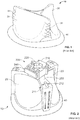
- FIG. 1 illustrates a typical prosthetic heart valve 10 according to the prior art to be used as a replacement for an excised native heart valve of a patient.
- the valve 10 includes a plurality of leaflets 20. Although a tricuspid valve is illustrated in FIG. 1 , other configurations, such as bicuspid valves, may be used to replace a native heart valve.
- the leaflets 20 may be connected to a stent that provides structural support to the leaflets. For example, each leaflet 20 may be attached to commissure posts 30 extending generally axially from a base of the stent. In the valve 10 illustrated in FIG. 1 , the leaflets 20 are positioned on an external portion of the stent. In other valves, the leaflets 20 may be positioned on an internal portion of the stent.
- a suture ring or sewing cuff 40 may be attached to the stent and/or valve 10 at an inflow end of the valve.
- the cuff 40 is used to attach the valve 10 to the patient's heart tissue.
- the leaflets 20 may open at an outflow end to allow blood to flow through the valve in the antegrade direction, and coapt with one another to prevent blood from flowing back through the valve in the retrograde direction.
- sutures are generally passed through the sewing cuff 40 and heart tissue at the site of implantation while the valve is held approximately 6-8 inches above the heart. This positioning allows the surgeon working room and visibility for the procedure. Once the sutures are in place, the surgeon tightens the sutures to "parachute" the valve 10 into place and knots the sutures to fix the valve in its final position.
- Valve holder 200 generally includes a base 210 with an aperture 220 shaped to accept the shaft 232 of an elongated handle 230 (as seen in FIG. 3 ).
- the base may also include a locking mechanism 240 to lock the shaft 232 into base 210. Depressing the locking mechanism 240 releases the shaft 232 from the base 210 of the valve holder 200.
- Three fingers 250 extend radially outwardly from the base 210 and then downward generally parallel to a longitudinal axis of the valve 10. The fingers 250 are spaced from one another so as to correspond to the positions of commissure posts 30 of valve 10. Therefore, when the valve holder 200 is coupled to valve 10, fingers 250 will abut the commissure posts 30.
- the fingers 250 may be sutured to the valve 10 to fix the holder 200 in place relative to the valve.
- a suture 211 may pass through tracks in the finger 250, across the cuff 40, and further across a groove.
- the groove 212 allows a surgeon to easily cut the suture 211 when desired with a scalpel or other tool, by sliding the scalpel across the suture at the location of the groove.
- the surgeon may begin suturing the cuff 40 to the heart tissue as he or another person holds the valve 10 using the handle. Once the sutures are in place, the surgeon may use the handle 230 with the valve holder 200 to facilitate parachuting the valve 10 into its final position in the heart. When the valve 10 is near its final position, the surgeon may remove the handle 230 from the valve holder 200 and manually position the valve into its final position. The surgeon may confirm the position and knot the sutures to secure the valve 10 in this final position. Once the valve 10 is secure in its final position, the surgeon may cut the sutures fixing the valve 10 to the holder, and remove the holder (and the handle if still attached) from the patient. Although described with three fingers 250 for a tricuspid valve, it should be understood that the holder 200 may take on other configurations, such as a two finger configuration for supporting a bicuspid valve.
- the valve holder 200 generally functions to protect part of the valve 10 or the entire valve and to provide structural support to the valve during the implant procedure.
- a valve holder could also facilitate deflection of the commissure posts 30 radially inward. Inward deflection of the commissure posts 30 makes the valve 10 somewhat smaller to give the surgeon a better view and more room in the surgical space, and may facilitate movement of the valve through the body into its final position in the heart. If the surgeon finds the holder too bulky, he may remove the holder during the suture tying and/or parachuting steps, leaving the valve 10 unprotected and more likely to be damaged during final insertion and positioning of the valve in the heart. It would be preferable to have a valve holder with a smaller effective diameter, as well as a valve holder that facilitates inward deflection of the commissure posts 30 to decrease the size of the valve during implantation.
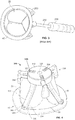
- FIG. 4 illustrates a valve holder 300 coupled to prosthetic heart valve 10. This configuration is outside the claimed scope.
- Valve holder 300 includes a generally cylindrical base 310 having a central aperture 320 for accepting the shaft of an elongated handle (not shown).
- a plurality of legs 330 extend downward and radially outward from the base 310. Three legs 330 are illustrated in this particular embodiment, but more or fewer legs may be provided depending on the number of leaflets in the particular prosthetic valve being implanted.
- the legs 330 are dimensioned to extend from the base 310 adjacent the outflow portion of the valve 10 to free ends 334 intended to lie adjacent cuff 40 when the valve holder 300 is assembled to the valve.
- the free ends 334 of the legs 330 may include an outwardly directed flange 336 which may include one or more apertures 340.
- sutures may be passed through the apertures 340 and through the cuff 40.
- the legs 330 When the valve holder 300 is coupled to the valve 10, the legs 330 generally run down cusps of the leaflets 20 between the commissure posts 30, and the flanges 336 of the legs 330 are generally parallel to the cuff 40.
- the legs 330 may be generally straight or may be curved to follow the contour of a respective valve leaflet 20.
- Valve holder 300 also includes a plurality of fingers 350. While there are three fingers 350 in the illustrated embodiment, a greater or lesser number of fingers may be provided depending on the number of commissure posts 30 in the particular prosthetic valve being implanted.
- Each finger 350 may include a rod-like portion 352 extending radially outward from an inner end fitted into a correspondingly shaped bore in the annular sidewall of base 310 to an outer end.
- a tip 354 may extend downwardly from the outer end of rod-like portion 352 in a direction generally perpendicular thereto.
- rod-like portion 352 may include a tab or protrusion 338 that projects in a direction opposite to tip 354. More particular, protrusion 338 projects toward the inner flat surface of base 310. In FIG. 4 , the protrusion 338 is not visible but is located in the base 310 in contact with a recess 356, described more fully below.
- the inner flat surface of base 310 may include multiple series of notches or recesses 356, with each series arranged in a linear array radially aligned with the rod-like portion 352 of a finger 350.
- recesses 356 are sized and shaped to receive the protrusions 338 on rod-like portions 352, thereby defining discrete positions at which the radial extension of fingers 350 is locked relative to base 310.
- the tip 354 of that finger may just barely contact a commissure post 30 without exerting much (or any) force on the particular commissure post.
- the finger 350 may be pushed radially inwardly toward the center of the base 310, with the applied force overcoming the engagement of protrusion 338 in recess 356, until the protrusion mates with another recess closer to the center of the base 310.
- the tip 354 of the finger 350 applies more force to the particular commissure post 30, causing the commissure post to deflect radially inwardly.
- the protrusions 338 may have a pawl shape such that the protrusions and the recesses 356 together act as a ratcheting mechanism.
- the fingers 350 may be pushed radially inwards toward the center of base 310 relatively easily to deflect the commissure posts 30 while resisting movement in the opposite direction. As a result, the inward deflection of the commissure posts 30 is generally irreversible until the holder 300 is removed from the valve 10.
- FIG. 4 illustrates holder 300 as having two recesses 356 for each finger 350
- more recesses may be provided for each finger so as to define additional positions at which the radial extension of the fingers may be locked relative to base 310.
- the commissure posts 30 may be deflected inwardly in more gradual increments.
- each finger 350 may move independently of the other fingers, each finger may deflect its respective commissure post 30 to a different degree. This independence of operation, as well as the provision of multiple recesses 356 for each finger 350, allows the surgeon a large degree of choice in determining how the valve 10 is to be constricted during an implantation procedure.
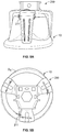
- FIGS. 5A-D depict valve holders 200 and 300 connected to the same size valve 10 in side-by-side views.
- valve holder 300 has a smaller effective diameter D 2 at the outflow end of the valve 10 when the valve is constricted compared with the effective diameter D 1 of valve holder 200 at the outflow end of the valve.
- valve holder 200 may have an effective diameter D 1 of approximately 27.0 mm at the outflow end of a 23 mm valve.
- valve holder 300 may have an effective diameter D 2 of approximately 22.5 mm at the outflow end of a 23 mm valve. This smaller diameter may make it easier for a surgeon to work in the surgical field during implantation of valve 10.
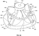
- FIG. 6A illustrates an embodiment of the claimed combination comprising a valve holder 400 coupled to the prosthetic heart valve 10.
- Valve holder 400 is similar to valve holder 300 in many respects.
- valve holder 400 includes a generally cylindrical base 410 having a central aperture 420 for accepting the shaft of an elongated handle (not shown).
- a plurality of legs 430 extend downward and radially outward from the base 410. Three legs 430 are illustrated in this particular embodiment, but a greater or lesser number of legs may be provided depending on the number of leaflets in the prosthetic valve being implanted.
- the legs 430 are dimensioned to extend from the base 410 adjacent the outflow portion of the valve 10 to free ends 434 intended to lie adjacent cuff 40 when the valve holder 400 is assembled to the valve.
- the free ends 434 of the legs 430 may include an outwardly directed flange 436 which may include one or more apertures 440.
- sutures may be passed through the apertures 440 and through the cuff 40.
- the legs 430 When the valve holder 400 is coupled to the valve 10, the legs 430 generally run down cusps of the leaflets 20 between the commissure posts 30, and the flanges 436 of the legs 430 are generally parallel to the cuff 40.
- the legs 430 may be straight or may be curved to follow the contour of a respective valve leaflet 20.
- a ring holder 450 projects radially outward from each leg 430 at about the midpoint between base 410 and the flange 436 at the end of the leg. Ring holders 450 are fully enclosed on three sides and have an open slot 452 on a side facing toward base 410.
- a wire ring 460 may be assembled in ring holders 450 so as to be rotatable relative to legs 430 about an axis passing through the center of base 410.
- the wire ring 460 has a generally triangular shape with three substantially straight sides 464 joined by rounded connectors 462. As a result of its triangular configuration, the distance between the center of the wire ring 460 and the rounded corners 462 is greater than the distance between the center of the wire ring and the substantially straight sides 464.
- the rounded connectors 462 are radially aligned with the commissure posts 30. Because the distance between the center of wire ring 460 and the connectors 462 is about equal to or greater than the distance between the center of valve 10 and the unconstricted commissure posts 30, the rounded connectors may barely contact the commissure posts in this position, and thus apply little or no inward pressure to the commissure posts.
- the wire ring 460 is rotated 60° to a constricted configuration as illustrated in FIG. 6C , the substantially straight sides 464 of the ring are radially aligned with the commissure posts 30.
- one or more bosses 466 may be provided on the wire ring for the user to grasp.
- a tool (not illustrated) may be provided to releasably connect to the bosses 466 to facilitate rotation.
- such a tool may be a generally hollow cylinder with recesses in the wall of the cylinder corresponding to the location of the bosses 466.
- wire ring 460 is illustrated as having a triangular shape, other shapes may be effective to achieve a similar result.
- a generally elliptically shaped wire ring may be effective to constrict a valve with two coapting leaflets and two commissure posts.
- FIG. 7A illustrates a further valve holder 500 coupled to the prosthetic heart valve 10. This configuration is outside the claimed scope.
- Valve holder 500 is similar to valve holders 200, 300 and 400 in many respects.
- valve holder 500 includes a generally cylindrical base 510 having a central aperture 520 for accepting the shaft of an elongated handle (not shown).
- a plurality of legs 530 extend downward and radially outward from the base 510. Although this particular embodiment shows three legs 530, a greater or lesser number of legs may be provided depending on the number of leaflets in the prosthetic valve being implanted.
- the legs 530 are dimensioned to extend from the base 510 adjacent the outflow portion of the valve 10 to free ends 534 intended to lie adjacent cuff 40 when the valve holder 500 is assembled to the valve.
- the free ends 534 of the legs 530 may include an outwardly directed flange 536 which may include one or more apertures 540.
- sutures may be passed through the apertures 540 and through the cuff 40.
- the legs 530 When the valve holder 500 is coupled to the valve 10, the legs 530 generally run down cusps of the leaflets 20 between the commissure posts 30, and the flanges 536 of the legs 530 are generally parallel to the cuff 40.
- the legs 530 may be straight or may be curved to follow the contour of a respective valve leaflet 20.
- the valve holder 500 includes a plurality of generally arcuate fingers 550, with each finger projecting laterally from a leg 530 at a point just below the point at which the leg joins base 510.
- each leg 530 may include a pair of laterally projecting spaced tabs 552 each having an aperture 553 therein.
- One end of each finger 550 may include a transverse through bore (not shown). The end of finger 550 may be inserted between tabs 552 with the through bore aligned with apertures 553.
- a pin 554 extending through the apertures 553 and the through bore in the finger 550 may pivotally join the finger to leg 530.
- Fingers 550 may be joined to legs 530 so that, when holder 500 is mounted to a valve 10, the concave sides of the fingers face toward the valve with the free ends of the fingers disposed radially outward of the commissure posts 30.
- each finger 550 may include a groove 556, with one or more retaining features 558 extending across the groove.
- One or more sutures may be threaded under retaining features 558 and through the grooves 556 before coupling to a handle 535, shown in FIG. 7B .
- a length of suture may be threaded from the free end of one finger 550 under the retaining features 558 and through the groove 556 of the finger, around the retaining feature farthest from the free end of the finger, and then back over the retaining features to the free end of the finger.
- the two free ends of the suture may then be coupled to handle 535 so that the suture wraps around a shaft or other structure of the handle and is drawn in as the handle is rotated.
- the suture exerts a radially inward force on the free end of the finger 550 to which it is attached, causing the finger to pivot radially inwardly and to simultaneously deflect the adjacent commissure post 30 radially inwardly to a constricted condition.
- a similar length of suture may couple each of the other fingers 550 to the handle 535 and may operate in the same manner to draw the other fingers radially inwardly, and with them, the other commissure posts 30.
- one (or more) sutures may extend to the top base 510 the holder 500 around a spool feature in the base 510. That spool feature may be rotated by a user via the handle similar to that shown in FIG. 3 . As the spool rotates, it takes up the suture and thus pulls the fingers radially inward to deflect the commissure posts 30.
- the spool feature may also contain a ratchet mechanism that allows the user to remove the handle and keep the fingers 550 and commissure posts 30 constricted. After implantation, the suture coupled to the fingers 550 may be cut to release the fingers 550 from the restricted configuration. Alternately or in addition, the user may cut the suture connecting the legs 530 of the holder 500 to the cuff 40 of the valve 10 to release the holder from the valve.
- one end of the length of suture may be secured to that retaining feature or to another point on the finger with the suture extending around the free end of the finger.
- the other end of the suture may be coupled to handle 535 for takeup by the handle as it is rotated, thereby pivoting the finger radially inwardly and simultaneously deflecting the adjacent commissure post 30 radially inwardly to the constricted condition.
- a single length of suture may be coupled to all of the fingers 550 and to handle 535. More particularly, one end of the length of suture may be secured to a retaining feature 558 or other structure on a first finger 550. That length of suture may then be threaded under the other retaining features 558 and through the groove 556 toward the free end of that first finger 550. The suture may then be directed to the connected or pivoting end of the next adjacent finger 550, and under the retaining features 558 and through the groove 556 of that finger toward its free end. This suture threading procedure may be repeated for the other two fingers 550, following which the free end of the suture may be coupled to handle 535.
- the suture will wrap around a shaft or other structure of the handle and cause each of fingers 550 to pivot radially inwardly.
- the inward pivoting of fingers 550 will simultaneously deflect the adjacent commissure posts 30 radially inwardly to the constricted condition.
- the handle 535 may include a known type of ratcheting mechanism so that, if the handle is released after inward deflection of the commissure posts 30, 10, the handle does not rotate in the opposite direction to unwind the suture and thereby release the commissure posts 30 from the constricted condition.
- the holders themselves may include a ratcheted spool mechanism. This may be preferable over a spool and ratcheting mechanism in the handle 535 as the handle 535 may be removed without disturbing the position of the spool and ratcheting mechanism in the holder.
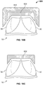
- FIG. 7C is a top view of the valve holder 500 and valve 10 in an unconstricted configuration prior to the suture being spooled onto the handle 535.
- FIG. 7D is a top view of the valve holder 500 and valve 10 in a constricted configuration after the suture has been spooled onto the handle 535, pulling the fingers 550 and the commissure posts 30 radially inward.
- fingers 550 protect the tissue portions of valve 10, preventing the suture from cutting or otherwise damaging the leaflets 20 or other portions of valve tissue.
- each of fingers 550' may have a ratcheting mechanism 560', as illustrated in FIG. 7E .
- Ratcheting mechanism 560' eliminates the need for any sutures, and allows for independent inward deflection of each finger 550' and the commissure post 30 associated therewith.
- fingers 550' are identical to fingers 550, except the connected or pivoting end of fingers 550' include a pawl 560'.
- Each leg 530' includes a plurality of teeth 570' positioned between the tabs (not shown in this embodiment) to which the finger is pivotally connected.
- the pawl 560' will engage successive teeth 570'.
- the pawl 560' and teeth 570' may have a ratcheting relationship such that the finger 550' may pivot in the radially inward direction D, but not in the reverse direction.
- a stop (not illustrated) may be provided on the leg 530' after a final tooth 570' such that the finger 550' may pivot radially inward by only a predetermined amount.
- FIG. 8A illustrates still another valve holder 600 coupled to a prosthetic heart valve 10. This configuration is outside the claimed scope.
- the valve 10 is shown as partially transparent to illustrate portions of the valve holder 600 located within the valve.
- Valve holder 600 is similar to valve holders 200, 300, 400 and 500 in many respects.
- valve holder 600 includes a generally cylindrical or hemispherical base 610 having a central aperture 620 for accepting the shaft of an elongated handle (not shown).
- a plurality of legs 630 extend downward and radially outward from the base 610. Three legs 630 are illustrated in this particular embodiment, but the valve holder 600 may include a greater or lesser number of legs depending on the number of leaflets in the prosthetic valve being implanted.
- the legs 630 are dimensioned to extend from the base 610 adjacent the outflow portion of the valve 10 to free ends 634 intended to lie adjacent cuff 40 when the valve holder 600 is assembled to the valve.
- the free ends 634 of the legs 630 may include an outwardly directed flange 636 which may include one or more apertures 640.
- sutures may be passed through the apertures 640 and through the cuff 40.
- Apertures 642 may also be included in legs 630 adjacent base 610. If desired, the suture connecting the cuff 40 to the legs 630 through apertures 640 may extend further across apertures 642. By using these extra apertures 642, the suture extends across a gap closer to the surgeon than the sutures in the cuff 40.
- valve holder 600 This allows a surgeon to release the valve holder 600 form the valve 10 by cutting the suture where it extends through apertures 642. This may be more convenient than if the surgeon attempted to cut a suture only attached to cuff 40 with apertures 640.
- This or similar features may be added to other embodiments of valve holders described herein to facilitate easy release of the valve 10 from the particular valve holder.
- the legs 630 When the valve holder 600 is coupled to the valve 10, the legs 630 generally run down cusps of the leaflets 20 between the commissure posts 30, and the flanges 636 of the legs 630 are generally parallel to the cuff 40.
- the legs 630 may be generally straight or may be curved to follow the contour of a respective leaflet 20 of the valve 10.
- Valve holder 600 further includes a hub 650 intended to be positioned below leaflets 20 of valve 10, and to project upward through the interface between the leaflets for connection to the underside of base 610.
- the hub 650 includes a plurality of pads 652 extending radially outward therefrom.
- the hub 650 includes three pads 652, but a greater or lesser number of pads may be provided depending on the number of leaflets in the valve being implanted.
- the pads 652 are configured to extend radially outward, each pad extending toward a respective commissure post 30.
- the pads 652 are dimensioned such that they do not extend fully to their respective commissure posts 30, but rather define a gap between the ends of the pads and the commissure posts.
- the diameter of the commissure posts may be approximately 20 mm and the diameter of a circle defined by the outer surfaces of the pads 652 may be approximately 18 mm, leaving a gap of about 2 mm therebetween.
- valve holder 600 does not significantly change the outer diameter of the valve 10 since it does not include any mechanisms for inwardly deflecting the commissure posts 30.
- the configuration and positions of the pads 652 allows for only limited inward deflection of the commissure posts 30 during implantation. For example, if the valve 10 is passed through a tube or other constricted area and inward forces are applied to the commissure posts 30, the commissure posts may deflect inwardly only until contacting a respective pad 652. Similarly, a user may manually deflect the commissure posts 30 during implantation only up to the point at which the commissure posts contact their respective pads 652. This type of inward deflection may be referred to as passive constriction.
- valve holder 600 may be connected to valve 10 prior to storage of the valve, such that the end user need not assemble the valve holder to the valve. This is due, at least in part, to the fact that the pads 652 do not exert any force on the commissure posts 30 when the valve is in an unconstricted state. This reduces or eliminates the likelihood that the valve 10 will be deformed by the holder 600 during storage prior to use.
- Each leg 630 may optionally include a pocket 645.
- the pocket 645 is generally defined by an inner wall and an outer wall.
- the inner wall may be the leg 630, with the outer wall extending out from the leg 630.
- the inner wall may be defined by a recess in the leg 630, with the space between the inner wall recess and leg 630 defining the pocket.
- a pocket 645 is formed in the leg 630 that may function to accept a tool, such as forceps or another guiding tool.
- One benefit of having one or more pockets 645 is that, during insertion of the valve, it surgeon may wish to grab the valve holder 600 manually or with a tool to facilitate positioning of the valve 10.
- the pockets 645 may accept forceps (or other tools) to facilitate the surgeon's ability to more precisely guide the valve 10 and valve holder 600. Particularly, this may be useful for valves 10 with tissue leaflets on the outer surfaces, as any handling, especially forceful handling, of the outer tissue surface of the valve 10 may compromise the valve. With the addition of one or more pockets 645, the surgeon may more easily guide the valve 10 into its proper position. Pockets 645 may also be provided with other embodiments of valve holders described herein.
- FIGS. 8B-C An alternate configuration of the base 610 and hub 650 is illustrated in FIGS. 8B-C .
- the hub 650' has a plurality of radially projecting pads 652' which are similar to pads 652 of valve holder 600. That is, pads 652' project toward the commissure posts 30 of valve 10 when hub 650' is connected to the valve, but are spaced therefrom so as to define a gap between the ends of the pads and the commissure posts. Although three pads 652' are shown on hub 650', a greater or lesser number of pads may be provided depending on the number of leaflets in the valve being implanted.
- a plurality of legs, similar to legs 630 of valve holder 600, extend from base 610' but have been omitted in the illustration for clarity.
- Base 610' includes a generally cylindrical shaft 655' configured for insertion into a corresponding bore 656' in the hub 650'.
- Shaft 655' may include a resilient tab 657' configured to snap into a similarly shaped aperture 658' in the hub 650' to lock the base 610' to the hub.
- This two-piece configuration may be useful so that the hub 650' may be inserted into the valve 10 through the inflow end, and the base 610' may be passed through the outflow end of the valve, as illustrated in FIG. 8C , for connection to the hub. Assembling the valve holder in this manner may be easier than attempting to insert the entire holder through the inflow or outflow portion of the valve 10.
- This embodiment may also be of further benefit by reducing extended contact of the pads 652' with the tissue of leaflets 20 during extended storage.
- the valve 10 and holder may be stored together for upwards of three years without any or significant detrimental effect on the valve 10 due to the holder, and particularly the pads 652'.
- FIG. 9 illustrates yet a further valve holder 700.
- Valve holder 700 includes a shield 710 having three generally upright curved walls 712 that conform to the shape of the leaflets 20 when the leaflets are in a mostly or fully coapted condition.
- the shield 710 may be formed of a polymer or any other suitable material, preferably as a single continuous structure, and acts to protect the tissue leaflets 20 as well as other structural components of the valve 10, such as a stent, during implantation of the valve 10.
- a plurality of flanges 720 are spaced around the bottom circumference of the shield 710, each flange having apertures 730.
- a suture may be passed through the apertures 730 into the cuff 40 to secure the valve holder 700 to the valve 10.
- the top of the shield 710 may include a base similar to other embodiments described above for attaching a handle to the valve holder 700.
- FIG. 10A illustrates a cross-sectional view of a further valve holder 800.
- the valve holder 800 includes a generally cylindrical outer body 810 having a circular top 812 with a cylindrical wall 814 depending therefrom.
- the free end of the cylindrical wall 814 is tapered such that the outermost surface of the wall extends farther from the circular top 812 than the innermost surface of the wall.
- This tapered end of wall 814 forms a first guide surface 816.
- Valve holder 800 also includes a generally cylindrical inner body 820 which is substantially identical to, but smaller than, the outer body 810.
- the inner body 820 has a circular top 822 with a cylindrical wall 824 depending therefrom.
- the free end of the wall 824 is also tapered similarly to the free end of cylindrical wall 814 to form a second guide surface 826.
- the inner body 820 is sized to fit within the cylindrical wall 814 of the outer body 810.
- the first guide surface 816 and the second guide surface 826 generally align with one another to form a continuous or nearly continuous guide surface.
- the inner body 820 Prior to implantation of valve 10, the inner body 820 may be assembled in the outer body 810 and advanced over the outflow portion of valve 10, as illustrated in FIG. 10B .
- the first guide surface 816 of the outer body may contact the commissure posts 30, deflecting them radially inward.
- the second guide surface 826 of the inner body 820 may also contact the commissure posts 30, deflecting them radially inward even farther.
- the outer body 810 may be removed, leaving the inner body 820 in place, as illustrated in FIG. 10C .
- the commissure posts 30 remain constricted, but the effective diameter of the valve holder 800 is reduced by removal of the larger outer body 810.
- the inner body 820 and/or the outer body 810 may include an aperture for connecting a handle to the holder 800 in a manner similar to those described above in connection with the other embodiments of the valve holder.
- the valve holder 800 has been described as including outer and inner bodies with circular top portions 812, 822 and cylindrical walls 814, 824, the bodies need not have fully circular top portions or fully cylindrical walls.
- the holder 800 may have a tri-lobe shape with walls extending from the tri-lobe shape in three discrete locations corresponding to the locations of the commissure posts.
- more than two bodies may be provided, with the ultimate goal of minimizing the size of the innermost body that remains in place while still enabling that body to provide sufficient support to the commissure posts 30 to keep them in a constricted configuration.
Description
- The present application claims the benefit of the filing date of
U.S. Provisional Application No. 61/640,522, filed April 30, 2012 U.S. Patent Application No. 13/826,148, filed March 14, 2013 - The current disclosure relates to prosthetic heart valves, and more particularly to apparatus for use in holding such valves prior to and during implantation of the valve in a patient.
- Prosthetic heart valves are used for replacing diseased and/or deficient valves in a patient's heart. For example, a patient's mitral and/or aortic valves may need to be replaced by such prostheses. One illustrative type of prosthetic heart valve includes animal tissue that has been treated to make it suitable for long-term use in a patient's body. The valve implantation may be done in an "open heart" surgical procedure or a minimally invasive procedure.
- During the implantation procedure, it may be desirable to temporarily modify the shape of the prosthetic tissue valve in certain respects in order to facilitate placement of the valve in the patient with good visualization and with good access for suturing the valve to the native tissue of the patient. For example, this temporary shape modification may include deflecting free end portions of the commissural posts of the prosthetic tissue valve radially inwardly. This shape modification is preferably done just prior to the implantation procedure to avoid any part of the valve taking an undesirable "set" during prolonged deformation, and may be especially useful in minimally invasive procedures in which there is limited space for a surgeon to work. Typical valve holders are disclosed, for example, in
U.S. Patent Nos. 4,865,600 ,6,214,043 ,6,409,758 ,7,568,073 ,7,503,929 andRE42,395 .US 2004/024451 A1 relates to a prosthetic heart valve system including a prosthetic heart valve and a deflection device. The deflection device includes a line and a connector assembly including a tensioning component. The line interconnects and passes through free ends of stent posts associated with the heart valve, and is further connected to the tensioning component. A holder body, coupled to the heart valve apart from the deflection device, may also be included. - The above aspects of prosthetic tissue valve handling may be aided by associating the valve with a so-called holder. This association may include, for example, a suture connection between the valve and the holder. The holder can be used to hold the valve in its storage liquid. When it is desired to use, or implant, the valve, a handle can be removably attached to the holder to remove the holder and valve from the storage liquid and to hold those components during the rinsing of the valve. Attachment of the handle to the holder (or subsequent manipulation of the handle relative to the holder) may also be used to cause the above-described temporary deformation of the valve. The handle may also be used to place the holder and valve in the patient. The handle may be removed from the holder during suturing of the valve into the patient. The handle may then be re-attached to the holder so that when the sutures connecting the valve to the holder are cut, the handle can be used to remove the holder from the patient, leaving only the valve in the patient.
- Holders that are large, bulky, or that increase the effective diameter of the valve being held, may be undesirable. For example, if a surgeon is implanting a valve connected to a holder into a patient, a bulky holder may limit the ability for the surgeon to visualize the surgical working area. A surgeon may thus be provoked into removing the valve from a bulky holder during implantation. Without the protection of the holder, the valve may be more likely to be damaged during implantation.
- From the foregoing it will be seen that a less bulky prosthetic valve holder that protects the valve and has the ability to decrease the valve profile is desired.
- The present disclosure relates to a holder adapted for connection to a prosthetic valve in an assembled condition. The prosthetic valve may include a stent having a plurality of commissure posts. The holder may include a base. The holder may also include a plurality of legs extending in a direction from a first end connected to the base toward a free end, the direction including a component in an axial direction. The holder may further include a hub extending from the base in the axial direction, the hub having a plurality of pads extending radially outward and defining a circle having a hub diameter. The commissure posts of the stent may define a circle having a stent diameter, the stent diameter being greater than the hub diameter. In the assembled condition, each of the pads may be adapted to align with a respective one of the commissure posts. The base may include a shaft extending in the axial direction. The hub may include a bore defined by a wall of the hub, the bore being configured to slidingly mate with the shaft. The shaft may include a resilient tab and the wall of the hub may include an aperture configured to matingly receive the tab in an assembled relationship.
- The invention in accordance with claim 1 relates to a combination of a prosthetic valve including a stent having a plurality of commissure posts and a plurality of leaflets connected to the stent, and a holder adapted for connection to a prosthetic valve in an assembled condition. The holder includes a base and a plurality of legs, each leg extending downward and radially outward from the base in a direction from a first end connected to the base toward a free end. The holder further comprises a ring holder extending radially outward from each one of the plurality of legs. The holder also includes a wire ring having a central axis and a plurality of substantially straight sides joined by a plurality of connectors. The plurality of substantially straight sides are spaced closer to the central axis than the plurality of connectors, the wire ring being mounted in the ring holders in the assembled condition so as to surround the plurality of commissure posts and being rotatable about the central axis. The rotation of the wire ring causes the substantially straight sides of the wire ring to contact the commissure posts and deflect the commissure posts radially inward. The prosthetic valve may in the assembled condition have a constricted configuration and an unconstricted configuration, each of the plurality of connectors being positioned radially outward of a respective one of the commissure posts and the plurality of commissure posts defining a circle having an unconstricted diameter in the unconstricted configuration. Each of the plurality of substantially straight sides may be positioned radially outward of a respective one of the commissure posts and the plurality of commissure posts may define a circle having a constricted diameter in the constricted configuration. The constricted diameter may be smaller than the unconstricted diameter. The prosthetic valve may include three commissure posts, and the wire ring may be generally triangular with three connectors and three substantially straight sides.
- The present disclosure also relates to a holder adapted for connection to a prosthetic valve in an assembled condition. The prosthetic valve may include a stent having a plurality of commissure posts. The holder may include a base and a plurality of legs extending in a direction from a first end connected to the base toward a free end, the direction including a component in an axial direction. The holder may further include a finger pivotably coupled to each one of the plurality of legs. Each one of the fingers may be arcuate with a concave surface and a convex surface, the concave surface being adapted to contact one of the plurality of commissure posts. The convex surface of each one of the fingers may include a groove and at least one retaining element extending across the groove. A suture may extend between the groove and the at least one retaining element of each one of the fingers, the suture having a tensioned state and a relaxed state. Each one of the fingers may be positioned radially outward of a respective one of the commissure posts and the plurality of commissure posts define a circle having an unconstricted diameter in the relaxed state of the suture. Each one of the fingers may be positioned radially outward of a respective one of the commissure posts and the plurality of commissure posts may define a circle having a constricted diameter in the tensioned state of the suture. The constricted diameter may be smaller than the unconstricted diameter. A plurality of teeth may be associated with each one of the plurality of legs. A pawl may be included on each one of the fingers, the pawl being adapted to engage respective ones of the plurality of teeth to temporarily lock the finger in a fixed position relative to a respective one of the commissure posts. Each one of the fingers may be configured to move independently of the other ones of the fingers. Each one of the pawls may be configured to mate with successive ones of the plurality of teeth in an incremental fashion, such that as the pawl moves from one of the plurality of teeth to an adjacent one of the plurality of teeth, the concave surface of the finger applies increasing force to deflect the respective one of the commissure posts radially inward.
- The present disclosure relates to a holder adapted for connection to a prosthetic valve in an assembled condition. The prosthetic valve may include a stent having a plurality of commissure posts. The holder may include a base having a plurality of radially oriented bores and a plurality of legs extending in a direction from a first end connected to the base toward a free end. The direction may include a component in a first axial direction. The holder may further include a plurality of fingers extending radially outward from the base, each one of the fingers including a rod like portion slidably disposed in one of the radially oriented bores and a tip extending generally orthogonal to the rod like portion. Each one of the rod like portions may include a protrusion and the base may include a plurality of recesses arranged in multiple series, each series of recesses being associated with one of the radially oriented bores and being arranged in a linear array radially aligned with a respective one of the rod like portions. The protrusion of the rod like portion may be configured to mate with the plurality of recesses in the series. Each one of the fingers may movable from a first position in which the protrusion of the rod like member mates with a first one of the recesses in the series to a second position in which the protrusion of the rod like portion mates with a second one of the recesses in the series. Each one of the tips may be positioned radially outward of a respective one of the commissure posts and the plurality of commissure posts may define a circle having an unconstricted diameter when each one of the fingers is in the first position. The plurality of commissure posts may define a circle having a constricted diameter when each one of the fingers is in the second position. The constricted diameter may be smaller than the unconstricted diameter.
-
-
FIG. 1 is a top perspective view of a prosthetic heart valve according to the prior art. -
FIG. 2 is a top perspective view of a valve holder according to the prior art coupled to the valve ofFIG. 1 . -
FIG. 3 is a bottom perspective view of a removable handle according to the prior art attached to the combination valve and valve holder ofFIG. 2 . -
FIG. 4 is a top perspective view of a valve holder in partial phantom lines coupled to the valve ofFIG. 1 . This configuration is outside the claimed scope. -
FIGS. 5A-B are side and top views of the combination valve and valve holder ofFIG. 2 according to the prior art. -
FIGS. 5C-D are side and top views of the combination valve and valve holder ofFIG. 4 . This configuration is outside the claimed scope. -
FIG. 6A is a top perspective view of an embodiment of the claimed combination of a valve holder coupled to a valve, in this embodiment the valve ofFIG. 1 . -
FIGS. 6B-C are top views of the combination valve and valve holder ofFIG. 6A in unconstricted and constricted configurations, respectively. -
FIG. 7A is a top perspective view of a further a valve holder coupled to the valve ofFIG. 1 . This configuration is outside the claimed scope. -
FIG. 7B is a side view of a handle attached to the valve holder ofFIG. 7A . This configuration is outside the claimed scope. -
FIGS. 7C-D are top views of the combination valve and valve holder ofFIG. 7A in unconstricted and constricted configurations, respectively. This configuration is outside the claimed scope -
FIG. 7E is an enlarged partial top view of an alternate embodiment of a finger and leg of the valve holder ofFIG. 7A . This configuration is outside the claimed scope -
FIG. 8A is a top perspective view of a a valve holder coupled to the valve ofFIG. 1 . This configuration is outside the claimed scope -
FIG. 8B is an exploded view of a hub component of the valve holder ofFIG. 8A . This configuration is outside the claimed scope -
FIG. 8C is a side view showing the assembly of the valve ofFIG. 1 to the hub component ofFIG. 8B . This configuration is outside the claimed scope -
FIG. 9 is a top perspective view of a valve holder coupled to the valve ofFIG. 1 . This configuration is outside the claimed scope -
FIG. 10A is a cross-sectional view of a valve holder before it is coupled to the valve ofFIG. 1 . This configuration is outside the claimed scope -
FIG. 10B is a cross-sectional view of the valve holder ofFIG. 10A coupled to the valve ofFIG. 1 . This configuration is outside the claimed scope -
FIG. 10C is a cross-sectional view of the valve holder ofFIG. 10A after a component thereof has been removed from the valve. This configuration is outside the claimed scope -
FIG. 1 illustrates a typicalprosthetic heart valve 10 according to the prior art to be used as a replacement for an excised native heart valve of a patient. Thevalve 10 includes a plurality ofleaflets 20. Although a tricuspid valve is illustrated inFIG. 1 , other configurations, such as bicuspid valves, may be used to replace a native heart valve. Theleaflets 20 may be connected to a stent that provides structural support to the leaflets. For example, eachleaflet 20 may be attached tocommissure posts 30 extending generally axially from a base of the stent. In thevalve 10 illustrated inFIG. 1 , theleaflets 20 are positioned on an external portion of the stent. In other valves, theleaflets 20 may be positioned on an internal portion of the stent. - A suture ring or
sewing cuff 40 may be attached to the stent and/orvalve 10 at an inflow end of the valve. Thecuff 40 is used to attach thevalve 10 to the patient's heart tissue. Theleaflets 20 may open at an outflow end to allow blood to flow through the valve in the antegrade direction, and coapt with one another to prevent blood from flowing back through the valve in the retrograde direction. - During implantation of the
valve 10 into a patient's heart, sutures are generally passed through thesewing cuff 40 and heart tissue at the site of implantation while the valve is held approximately 6-8 inches above the heart. This positioning allows the surgeon working room and visibility for the procedure. Once the sutures are in place, the surgeon tightens the sutures to "parachute" thevalve 10 into place and knots the sutures to fix the valve in its final position. - A
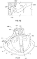
valve holder 200 according to the prior art is illustrated inFIG. 2 attached tovalve 10.Valve holder 200 generally includes a base 210 with anaperture 220 shaped to accept theshaft 232 of an elongated handle 230 (as seen inFIG. 3 ). The base may also include alocking mechanism 240 to lock theshaft 232 intobase 210. Depressing thelocking mechanism 240 releases theshaft 232 from thebase 210 of thevalve holder 200. Threefingers 250 extend radially outwardly from thebase 210 and then downward generally parallel to a longitudinal axis of thevalve 10. Thefingers 250 are spaced from one another so as to correspond to the positions of commissure posts 30 ofvalve 10. Therefore, when thevalve holder 200 is coupled tovalve 10,fingers 250 will abut the commissure posts 30. Thefingers 250 may be sutured to thevalve 10 to fix theholder 200 in place relative to the valve. Asuture 211 may pass through tracks in thefinger 250, across thecuff 40, and further across a groove. Thegroove 212 allows a surgeon to easily cut thesuture 211 when desired with a scalpel or other tool, by sliding the scalpel across the suture at the location of the groove. - After the
handle 230 is attached to theholder 200, the surgeon may begin suturing thecuff 40 to the heart tissue as he or another person holds thevalve 10 using the handle. Once the sutures are in place, the surgeon may use thehandle 230 with thevalve holder 200 to facilitate parachuting thevalve 10 into its final position in the heart. When thevalve 10 is near its final position, the surgeon may remove thehandle 230 from thevalve holder 200 and manually position the valve into its final position. The surgeon may confirm the position and knot the sutures to secure thevalve 10 in this final position. Once thevalve 10 is secure in its final position, the surgeon may cut the sutures fixing thevalve 10 to the holder, and remove the holder (and the handle if still attached) from the patient. Although described with threefingers 250 for a tricuspid valve, it should be understood that theholder 200 may take on other configurations, such as a two finger configuration for supporting a bicuspid valve. - The
valve holder 200 generally functions to protect part of thevalve 10 or the entire valve and to provide structural support to the valve during the implant procedure. - It would be preferable if a valve holder could also facilitate deflection of the commissure posts 30 radially inward. Inward deflection of the commissure posts 30 makes the
valve 10 somewhat smaller to give the surgeon a better view and more room in the surgical space, and may facilitate movement of the valve through the body into its final position in the heart. If the surgeon finds the holder too bulky, he may remove the holder during the suture tying and/or parachuting steps, leaving thevalve 10 unprotected and more likely to be damaged during final insertion and positioning of the valve in the heart. It would be preferable to have a valve holder with a smaller effective diameter, as well as a valve holder that facilitates inward deflection of the commissure posts 30 to decrease the size of the valve during implantation. -
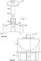
FIG. 4 illustrates avalve holder 300 coupled toprosthetic heart valve 10. This configuration is outside the claimed scope.Valve holder 300 includes a generallycylindrical base 310 having acentral aperture 320 for accepting the shaft of an elongated handle (not shown). A plurality oflegs 330 extend downward and radially outward from thebase 310. Threelegs 330 are illustrated in this particular embodiment, but more or fewer legs may be provided depending on the number of leaflets in the particular prosthetic valve being implanted. Thelegs 330 are dimensioned to extend from the base 310 adjacent the outflow portion of thevalve 10 to free ends 334 intended to lieadjacent cuff 40 when thevalve holder 300 is assembled to the valve. The free ends 334 of thelegs 330 may include an outwardly directedflange 336 which may include one ormore apertures 340. To fix thevalve holder 300 to thevalve 10, sutures may be passed through theapertures 340 and through thecuff 40. When thevalve holder 300 is coupled to thevalve 10, thelegs 330 generally run down cusps of theleaflets 20 between the commissure posts 30, and theflanges 336 of thelegs 330 are generally parallel to thecuff 40. Thelegs 330 may be generally straight or may be curved to follow the contour of arespective valve leaflet 20. -
Valve holder 300 also includes a plurality offingers 350. While there are threefingers 350 in the illustrated embodiment, a greater or lesser number of fingers may be provided depending on the number of commissure posts 30 in the particular prosthetic valve being implanted. Eachfinger 350 may include a rod-like portion 352 extending radially outward from an inner end fitted into a correspondingly shaped bore in the annular sidewall ofbase 310 to an outer end. Atip 354 may extend downwardly from the outer end of rod-like portion 352 in a direction generally perpendicular thereto. At its inner end, rod-like portion 352 may include a tab orprotrusion 338 that projects in a direction opposite to tip 354. More particular,protrusion 338 projects toward the inner flat surface ofbase 310. InFIG. 4 , theprotrusion 338 is not visible but is located in the base 310 in contact with arecess 356, described more fully below. - The inner flat surface of
base 310 may include multiple series of notches or recesses 356, with each series arranged in a linear array radially aligned with the rod-like portion 352 of afinger 350. Preferably, recesses 356 are sized and shaped to receive theprotrusions 338 on rod-like portions 352, thereby defining discrete positions at which the radial extension offingers 350 is locked relative tobase 310. - For example, when the
protrusion 338 of afinger 350 is in theoutermost recess 356, thetip 354 of that finger may just barely contact acommissure post 30 without exerting much (or any) force on the particular commissure post. Thefinger 350 may be pushed radially inwardly toward the center of thebase 310, with the applied force overcoming the engagement ofprotrusion 338 inrecess 356, until the protrusion mates with another recess closer to the center of thebase 310. In this new position, thetip 354 of thefinger 350 applies more force to theparticular commissure post 30, causing the commissure post to deflect radially inwardly. - The
protrusions 338 may have a pawl shape such that the protrusions and therecesses 356 together act as a ratcheting mechanism. In such arrangement, thefingers 350 may be pushed radially inwards toward the center ofbase 310 relatively easily to deflect the commissure posts 30 while resisting movement in the opposite direction. As a result, the inward deflection of the commissure posts 30 is generally irreversible until theholder 300 is removed from thevalve 10. - Although
FIG. 4 illustratesholder 300 as having tworecesses 356 for eachfinger 350, more recesses may be provided for each finger so as to define additional positions at which the radial extension of the fingers may be locked relative tobase 310. As a result of these additional positions, the commissure posts 30 may be deflected inwardly in more gradual increments. Further, since eachfinger 350 may move independently of the other fingers, each finger may deflect its respective commissure post 30 to a different degree. This independence of operation, as well as the provision ofmultiple recesses 356 for eachfinger 350, allows the surgeon a large degree of choice in determining how thevalve 10 is to be constricted during an implantation procedure. -
FIGS. 5A-D depictvalve holders same size valve 10 in side-by-side views. As can be seen, particularly from comparingFIGS. 5B and5D ,valve holder 300 has a smaller effective diameter D2 at the outflow end of thevalve 10 when the valve is constricted compared with the effective diameter D1 ofvalve holder 200 at the outflow end of the valve. For example,valve holder 200 may have an effective diameter D1 of approximately 27.0 mm at the outflow end of a 23 mm valve. When in the most constricted configuration,valve holder 300 may have an effective diameter D2 of approximately 22.5 mm at the outflow end of a 23 mm valve. This smaller diameter may make it easier for a surgeon to work in the surgical field during implantation ofvalve 10. -
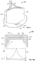
FIG. 6A illustrates an embodiment of the claimed combination comprising avalve holder 400 coupled to theprosthetic heart valve 10.Valve holder 400 is similar tovalve holder 300 in many respects. For example,valve holder 400 includes a generallycylindrical base 410 having acentral aperture 420 for accepting the shaft of an elongated handle (not shown). A plurality oflegs 430 extend downward and radially outward from thebase 410. Threelegs 430 are illustrated in this particular embodiment, but a greater or lesser number of legs may be provided depending on the number of leaflets in the prosthetic valve being implanted. Thelegs 430 are dimensioned to extend from the base 410 adjacent the outflow portion of thevalve 10 to free ends 434 intended to lieadjacent cuff 40 when thevalve holder 400 is assembled to the valve. The free ends 434 of thelegs 430 may include an outwardly directedflange 436 which may include one ormore apertures 440. To fix thevalve holder 400 to thevalve 10, sutures may be passed through theapertures 440 and through thecuff 40. When thevalve holder 400 is coupled to thevalve 10, thelegs 430 generally run down cusps of theleaflets 20 between the commissure posts 30, and theflanges 436 of thelegs 430 are generally parallel to thecuff 40. Thelegs 430 may be straight or may be curved to follow the contour of arespective valve leaflet 20. - A
ring holder 450 projects radially outward from eachleg 430 at about the midpoint betweenbase 410 and theflange 436 at the end of the leg.Ring holders 450 are fully enclosed on three sides and have an open slot 452 on a side facing towardbase 410. Awire ring 460 may be assembled inring holders 450 so as to be rotatable relative tolegs 430 about an axis passing through the center ofbase 410. Thewire ring 460 has a generally triangular shape with three substantiallystraight sides 464 joined byrounded connectors 462. As a result of its triangular configuration, the distance between the center of thewire ring 460 and therounded corners 462 is greater than the distance between the center of the wire ring and the substantially straight sides 464. Whenwire ring 460 is rotated to an unconstricted configuration as illustrated inFIGS. 6A and6B , therounded connectors 462 are radially aligned with the commissure posts 30. Because the distance between the center ofwire ring 460 and theconnectors 462 is about equal to or greater than the distance between the center ofvalve 10 and the unconstricted commissure posts 30, the rounded connectors may barely contact the commissure posts in this position, and thus apply little or no inward pressure to the commissure posts. When thewire ring 460 is rotated 60° to a constricted configuration as illustrated inFIG. 6C , the substantiallystraight sides 464 of the ring are radially aligned with the commissure posts 30. Because the distance between the center ofwire ring 460 andsides 464 is less than the distance between the center ofvalve 10 and the unconstricted commissure posts 30, the sides of the ring contact the commissure posts and deflect them radially inwardly. To facilitate the rotation ofwire ring 460 relative tolegs 430, one ormore bosses 466 may be provided on the wire ring for the user to grasp. Alternately, a tool (not illustrated) may be provided to releasably connect to thebosses 466 to facilitate rotation. For example, such a tool may be a generally hollow cylinder with recesses in the wall of the cylinder corresponding to the location of thebosses 466. Although thewire ring 460 is illustrated as having a triangular shape, other shapes may be effective to achieve a similar result. For example, a generally elliptically shaped wire ring may be effective to constrict a valve with two coapting leaflets and two commissure posts. -
FIG. 7A illustrates afurther valve holder 500 coupled to theprosthetic heart valve 10. This configuration is outside the claimed scope.Valve holder 500 is similar tovalve holders valve holder 500 includes a generallycylindrical base 510 having acentral aperture 520 for accepting the shaft of an elongated handle (not shown). A plurality oflegs 530 extend downward and radially outward from thebase 510. Although this particular embodiment shows threelegs 530, a greater or lesser number of legs may be provided depending on the number of leaflets in the prosthetic valve being implanted. Thelegs 530 are dimensioned to extend from the base 510 adjacent the outflow portion of thevalve 10 to free ends 534 intended to lieadjacent cuff 40 when thevalve holder 500 is assembled to the valve. The free ends 534 of thelegs 530 may include an outwardly directedflange 536 which may include one ormore apertures 540. To fix thevalve holder 500 to thevalve 10, sutures may be passed through theapertures 540 and through thecuff 40. When thevalve holder 500 is coupled to thevalve 10, thelegs 530 generally run down cusps of theleaflets 20 between the commissure posts 30, and theflanges 536 of thelegs 530 are generally parallel to thecuff 40. Thelegs 530 may be straight or may be curved to follow the contour of arespective valve leaflet 20. - The
valve holder 500 includes a plurality of generallyarcuate fingers 550, with each finger projecting laterally from aleg 530 at a point just below the point at which the leg joinsbase 510. In that regard, eachleg 530 may include a pair of laterally projecting spacedtabs 552 each having anaperture 553 therein. One end of eachfinger 550 may include a transverse through bore (not shown). The end offinger 550 may be inserted betweentabs 552 with the through bore aligned withapertures 553. Apin 554 extending through theapertures 553 and the through bore in thefinger 550 may pivotally join the finger toleg 530.Fingers 550 may be joined tolegs 530 so that, whenholder 500 is mounted to avalve 10, the concave sides of the fingers face toward the valve with the free ends of the fingers disposed radially outward of the commissure posts 30. - The outer convex surface of each
finger 550 may include agroove 556, with one or more retaining features 558 extending across the groove. One or more sutures (not illustrated) may be threaded under retainingfeatures 558 and through thegrooves 556 before coupling to ahandle 535, shown inFIG. 7B . In one arrangement, a length of suture may be threaded from the free end of onefinger 550 under the retaining features 558 and through thegroove 556 of the finger, around the retaining feature farthest from the free end of the finger, and then back over the retaining features to the free end of the finger. The two free ends of the suture may then be coupled to handle 535 so that the suture wraps around a shaft or other structure of the handle and is drawn in as the handle is rotated. As the suture is drawn in, it exerts a radially inward force on the free end of thefinger 550 to which it is attached, causing the finger to pivot radially inwardly and to simultaneously deflect theadjacent commissure post 30 radially inwardly to a constricted condition. A similar length of suture may couple each of theother fingers 550 to thehandle 535 and may operate in the same manner to draw the other fingers radially inwardly, and with them, the other commissure posts 30. - In a similar embodiment, one (or more) sutures may extend to the
top base 510 theholder 500 around a spool feature in thebase 510. That spool feature may be rotated by a user via the handle similar to that shown inFIG. 3 . As the spool rotates, it takes up the suture and thus pulls the fingers radially inward to deflect the commissure posts 30. The spool feature may also contain a ratchet mechanism that allows the user to remove the handle and keep thefingers 550 andcommissure posts 30 constricted. After implantation, the suture coupled to thefingers 550 may be cut to release thefingers 550 from the restricted configuration. Alternately or in addition, the user may cut the suture connecting thelegs 530 of theholder 500 to thecuff 40 of thevalve 10 to release the holder from the valve. - In another arrangement, rather than looping around the retaining
feature 558 farthest from the free end of afinger 550, one end of the length of suture may be secured to that retaining feature or to another point on the finger with the suture extending around the free end of the finger. The other end of the suture may be coupled to handle 535 for takeup by the handle as it is rotated, thereby pivoting the finger radially inwardly and simultaneously deflecting theadjacent commissure post 30 radially inwardly to the constricted condition. - In a still further arrangement, a single length of suture may be coupled to all of the
fingers 550 and to handle 535. More particularly, one end of the length of suture may be secured to aretaining feature 558 or other structure on afirst finger 550. That length of suture may then be threaded under the other retaining features 558 and through thegroove 556 toward the free end of thatfirst finger 550. The suture may then be directed to the connected or pivoting end of the nextadjacent finger 550, and under the retaining features 558 and through thegroove 556 of that finger toward its free end. This suture threading procedure may be repeated for the other twofingers 550, following which the free end of the suture may be coupled to handle 535. As thehandle 535 is rotated, the suture will wrap around a shaft or other structure of the handle and cause each offingers 550 to pivot radially inwardly. The inward pivoting offingers 550 will simultaneously deflect the adjacent commissure posts 30 radially inwardly to the constricted condition. - In each of the arrangements described above, the
handle 535 may include a known type of ratcheting mechanism so that, if the handle is released after inward deflection of the commissure posts 30, 10, the handle does not rotate in the opposite direction to unwind the suture and thereby release the commissure posts 30 from the constricted condition. Also, as described above, the holders themselves may include a ratcheted spool mechanism. This may be preferable over a spool and ratcheting mechanism in thehandle 535 as thehandle 535 may be removed without disturbing the position of the spool and ratcheting mechanism in the holder. -
FIG. 7C is a top view of thevalve holder 500 andvalve 10 in an unconstricted configuration prior to the suture being spooled onto thehandle 535.FIG. 7D is a top view of thevalve holder 500 andvalve 10 in a constricted configuration after the suture has been spooled onto thehandle 535, pulling thefingers 550 and the commissure posts 30 radially inward. In each of the arrangements described above,fingers 550 protect the tissue portions ofvalve 10, preventing the suture from cutting or otherwise damaging theleaflets 20 or other portions of valve tissue. - Generally, the inward deflection or constriction described in connection with
valve holder 500 inFIGS. 7A-D causes simultaneous constriction of eachcommissure post 30 as the suture is spooled onto thehandle 535. In a variant ofvalve holder 500, each of fingers 550' may have a ratcheting mechanism 560', as illustrated inFIG. 7E . Ratcheting mechanism 560' eliminates the need for any sutures, and allows for independent inward deflection of each finger 550' and thecommissure post 30 associated therewith. Generally, fingers 550' are identical tofingers 550, except the connected or pivoting end of fingers 550' include a pawl 560'. Each leg 530' includes a plurality of teeth 570' positioned between the tabs (not shown in this embodiment) to which the finger is pivotally connected. As the finger 550' is pivoted radially inwardly in the direction of arrow D, the pawl 560' will engage successive teeth 570'. The pawl 560' and teeth 570' may have a ratcheting relationship such that the finger 550' may pivot in the radially inward direction D, but not in the reverse direction. A stop (not illustrated) may be provided on the leg 530' after a final tooth 570' such that the finger 550' may pivot radially inward by only a predetermined amount. With this configuration, a user may manually manipulate each finger 550' to inwardly deflect eachcommissure post 30 independently to a desired level of constriction and hold it in the constricted condition during the implantation procedure. -
FIG. 8A illustrates still anothervalve holder 600 coupled to aprosthetic heart valve 10. This configuration is outside the claimed scope. Thevalve 10 is shown as partially transparent to illustrate portions of thevalve holder 600 located within the valve.Valve holder 600 is similar tovalve holders valve holder 600 includes a generally cylindrical orhemispherical base 610 having a central aperture 620 for accepting the shaft of an elongated handle (not shown). A plurality oflegs 630 extend downward and radially outward from thebase 610. Threelegs 630 are illustrated in this particular embodiment, but thevalve holder 600 may include a greater or lesser number of legs depending on the number of leaflets in the prosthetic valve being implanted. Thelegs 630 are dimensioned to extend from the base 610 adjacent the outflow portion of thevalve 10 to free ends 634 intended to lieadjacent cuff 40 when thevalve holder 600 is assembled to the valve. The free ends 634 of thelegs 630 may include an outwardly directedflange 636 which may include one ormore apertures 640. To fix thevalve holder 600 to thevalve 10, sutures may be passed through theapertures 640 and through thecuff 40.Apertures 642 may also be included inlegs 630adjacent base 610. If desired, the suture connecting thecuff 40 to thelegs 630 throughapertures 640 may extend further acrossapertures 642. By using theseextra apertures 642, the suture extends across a gap closer to the surgeon than the sutures in thecuff 40. This allows a surgeon to release thevalve holder 600 form thevalve 10 by cutting the suture where it extends throughapertures 642. This may be more convenient than if the surgeon attempted to cut a suture only attached to cuff 40 withapertures 640. This or similar features may be added to other embodiments of valve holders described herein to facilitate easy release of thevalve 10 from the particular valve holder. When thevalve holder 600 is coupled to thevalve 10, thelegs 630 generally run down cusps of theleaflets 20 between the commissure posts 30, and theflanges 636 of thelegs 630 are generally parallel to thecuff 40. Thelegs 630 may be generally straight or may be curved to follow the contour of arespective leaflet 20 of thevalve 10. -
Valve holder 600 further includes ahub 650 intended to be positioned belowleaflets 20 ofvalve 10, and to project upward through the interface between the leaflets for connection to the underside ofbase 610. Thehub 650 includes a plurality ofpads 652 extending radially outward therefrom. In the illustrated embodiment, thehub 650 includes threepads 652, but a greater or lesser number of pads may be provided depending on the number of leaflets in the valve being implanted. When thevalve holder 600 is coupled to thevalve 10, thepads 652 are configured to extend radially outward, each pad extending toward arespective commissure post 30. Thepads 652 are dimensioned such that they do not extend fully to their respective commissure posts 30, but rather define a gap between the ends of the pads and the commissure posts. For example, the diameter of the commissure posts may be approximately 20 mm and the diameter of a circle defined by the outer surfaces of thepads 652 may be approximately 18 mm, leaving a gap of about 2 mm therebetween. - In operation,
valve holder 600 does not significantly change the outer diameter of thevalve 10 since it does not include any mechanisms for inwardly deflecting the commissure posts 30. In addition, the configuration and positions of thepads 652 allows for only limited inward deflection of the commissure posts 30 during implantation. For example, if thevalve 10 is passed through a tube or other constricted area and inward forces are applied to the commissure posts 30, the commissure posts may deflect inwardly only until contacting arespective pad 652. Similarly, a user may manually deflect the commissure posts 30 during implantation only up to the point at which the commissure posts contact theirrespective pads 652. This type of inward deflection may be referred to as passive constriction. In addition to the benefits of a small profile and the provision of support to the leaflets, thevalve holder 600 may be connected tovalve 10 prior to storage of the valve, such that the end user need not assemble the valve holder to the valve. This is due, at least in part, to the fact that thepads 652 do not exert any force on the commissure posts 30 when the valve is in an unconstricted state. This reduces or eliminates the likelihood that thevalve 10 will be deformed by theholder 600 during storage prior to use. - Each
leg 630 may optionally include apocket 645. Thepocket 645 is generally defined by an inner wall and an outer wall. The inner wall may be theleg 630, with the outer wall extending out from theleg 630. Alternatively, the inner wall may be defined by a recess in theleg 630, with the space between the inner wall recess andleg 630 defining the pocket. In either case, apocket 645 is formed in theleg 630 that may function to accept a tool, such as forceps or another guiding tool. One benefit of having one ormore pockets 645 is that, during insertion of the valve, it surgeon may wish to grab thevalve holder 600 manually or with a tool to facilitate positioning of thevalve 10. Thepockets 645 may accept forceps (or other tools) to facilitate the surgeon's ability to more precisely guide thevalve 10 andvalve holder 600. Particularly, this may be useful forvalves 10 with tissue leaflets on the outer surfaces, as any handling, especially forceful handling, of the outer tissue surface of thevalve 10 may compromise the valve. With the addition of one ormore pockets 645, the surgeon may more easily guide thevalve 10 into its proper position.Pockets 645 may also be provided with other embodiments of valve holders described herein. - An alternate configuration of the
base 610 andhub 650 is illustrated inFIGS. 8B-C . The hub 650' has a plurality of radially projecting pads 652' which are similar topads 652 ofvalve holder 600. That is, pads 652' project toward the commissure posts 30 ofvalve 10 when hub 650' is connected to the valve, but are spaced therefrom so as to define a gap between the ends of the pads and the commissure posts. Although three pads 652' are shown on hub 650', a greater or lesser number of pads may be provided depending on the number of leaflets in the valve being implanted. A plurality of legs, similar tolegs 630 ofvalve holder 600, extend from base 610' but have been omitted in the illustration for clarity. Base 610' includes a generally cylindrical shaft 655' configured for insertion into a corresponding bore 656' in the hub 650'. Shaft 655' may include a resilient tab 657' configured to snap into a similarly shaped aperture 658' in the hub 650' to lock the base 610' to the hub. This two-piece configuration may be useful so that the hub 650' may be inserted into thevalve 10 through the inflow end, and the base 610' may be passed through the outflow end of the valve, as illustrated inFIG. 8C , for connection to the hub. Assembling the valve holder in this manner may be easier than attempting to insert the entire holder through the inflow or outflow portion of thevalve 10. This embodiment may also be of further benefit by reducing extended contact of the pads 652' with the tissue ofleaflets 20 during extended storage. Preferably, thevalve 10 and holder may be stored together for upwards of three years without any or significant detrimental effect on thevalve 10 due to the holder, and particularly the pads 652'. -
FIG. 9 illustrates yet afurther valve holder 700. This configuration is outside the claimed scope.Valve holder 700 includes ashield 710 having three generally uprightcurved walls 712 that conform to the shape of theleaflets 20 when the leaflets are in a mostly or fully coapted condition. Theshield 710 may be formed of a polymer or any other suitable material, preferably as a single continuous structure, and acts to protect thetissue leaflets 20 as well as other structural components of thevalve 10, such as a stent, during implantation of thevalve 10. A plurality offlanges 720 are spaced around the bottom circumference of theshield 710, eachflange having apertures 730. Similar to other embodiments described above, a suture may be passed through theapertures 730 into thecuff 40 to secure thevalve holder 700 to thevalve 10. Although not illustrated, the top of theshield 710 may include a base similar to other embodiments described above for attaching a handle to thevalve holder 700. -
FIG. 10A illustrates a cross-sectional view of afurther valve holder 800. This configuration is outside the claimed scope. Thevalve holder 800 includes a generally cylindricalouter body 810 having a circular top 812 with acylindrical wall 814 depending therefrom. The free end of thecylindrical wall 814 is tapered such that the outermost surface of the wall extends farther from the circular top 812 than the innermost surface of the wall. This tapered end ofwall 814 forms afirst guide surface 816.Valve holder 800 also includes a generally cylindricalinner body 820 which is substantially identical to, but smaller than, theouter body 810. Theinner body 820 has a circular top 822 with acylindrical wall 824 depending therefrom. The free end of thewall 824 is also tapered similarly to the free end ofcylindrical wall 814 to form asecond guide surface 826. - The
inner body 820 is sized to fit within thecylindrical wall 814 of theouter body 810. When theinner body 820 is positioned in theouter body 810, thefirst guide surface 816 and thesecond guide surface 826 generally align with one another to form a continuous or nearly continuous guide surface. Prior to implantation ofvalve 10, theinner body 820 may be assembled in theouter body 810 and advanced over the outflow portion ofvalve 10, as illustrated inFIG. 10B . As theassembly 810/820 is advanced, thefirst guide surface 816 of the outer body may contact the commissure posts 30, deflecting them radially inward. As advancement continues further, thesecond guide surface 826 of theinner body 820 may also contact the commissure posts 30, deflecting them radially inward even farther. - After the
assembly 810/820 has been advanced fully intovalve 10, theouter body 810 may be removed, leaving theinner body 820 in place, as illustrated inFIG. 10C . In this configuration, the commissure posts 30 remain constricted, but the effective diameter of thevalve holder 800 is reduced by removal of the largerouter body 810. Although not illustrated, theinner body 820 and/or theouter body 810 may include an aperture for connecting a handle to theholder 800 in a manner similar to those described above in connection with the other embodiments of the valve holder. Similarly, although thevalve holder 800 has been described as including outer and inner bodies with circulartop portions cylindrical walls valve 10. For avalve 10 with threeleaflets 20 and threecommissure posts 30, theholder 800 may have a tri-lobe shape with walls extending from the tri-lobe shape in three discrete locations corresponding to the locations of the commissure posts. Similarly, more than two bodies may be provided, with the ultimate goal of minimizing the size of the innermost body that remains in place while still enabling that body to provide sufficient support to the commissure posts 30 to keep them in a constricted configuration. - Although the invention herein has been described with reference to particular embodiments, it is to be understood that these embodiments are merely illustrative of the principles and applications of the present invention. It is therefore to be understood that numerous modifications may be made to the illustrative embodiments and that other arrangements may be devised without departing from the scope of the present invention as defined by the appended claims. Further components of certain embodiments disclosed herein may be combined with other described embodiments without departing from the scope of the invention.
- It will be appreciated that the various dependent claims and the features set forth therein can be combined in different ways than presented in the initial claims. It will also be appreciated that the features described in connection with individual embodiments may be shared with others of the described embodiments.
Claims (10)
- A combination of a prosthetic valve (10) including a stent having a plurality of commissure posts and a plurality of leaflets (20) connected to the stent; and
a holder (400) adapted for connection to the prosthetic valve in an assembled condition, the holder comprising:a base (410); anda plurality of legs (430), each leg extending downward and radially outward from the base in a direction from a first end connected to the base toward a free end (434); wherein the holder further comprisesa ring holder (450) extending radially outward from each one of the plurality of legs; anda wire ring (460) having a central axis and a plurality of substantially straight sides joined by a plurality of connectors, the plurality of substantially straight sides being spaced closer to the central axis than the plurality of connectors, the wire ring being mounted in the ring holders in the assembled condition so as to surround the plurality of commissure posts and being rotatable about the central axis, the rotation of the wire ring causing the substantially straight sides of the wire ring to contact the commissure posts and deflect the commissure posts radially inward. - The combination of claim 1, wherein the prosthetic valve in the assembled condition has a constricted configuration and an unconstricted configuration, each of the plurality of connectors being positioned radially outward of a respective one of the commissure posts and the plurality of commissure posts defining a circle having an unconstricted diameter in the unconstricted configuration, and each of the plurality of substantially straight sides being positioned radially outward of a respective one of the commissure posts and the plurality of commissure posts defining a circle having a constricted diameter in the constricted configuration, the constricted diameter being smaller than the unconstricted diameter.
- The combination of claim 2, wherein the prosthetic valve includes three commissure posts, and the wire ring is generally triangular with three connectors and three substantially straight sides.
- The combination of any one of the preceding claims, further comprising at least one boss (466) protruding from the wire ring.
- The combination of any one of the preceding claims, wherein each free end of the plurality of legs includes an outwardly directed flange (436).
- The combination of claim 5, wherein the flange includes at least one aperture (440).
- The combination of any one of the preceding claims, wherein each of the ring holders is positioned approximately at a mid-point in the direction between the first end connected to the base and the free end of the leg.
- The combination of any one of the preceding claims, wherein each of the ring holders is fully enclosed on three sides and has an open slot (452) on a side facing toward the base.
- The combination of any one of the claims 1-8, wherein the legs are straight from the first end to the free end.
- The combination of any one of the claims 1-8, wherein the legs are curved between the first end and the free end.
Applications Claiming Priority (3)
| Application Number | Priority Date | Filing Date | Title |
|---|---|---|---|
| US201261640522P | 2012-04-30 | 2012-04-30 | |
| US13/826,148 US20130289699A1 (en) | 2012-04-30 | 2013-03-14 | Aortic valve holder with stent protection and/or ability to decrease valve profile |
| PCT/US2013/038737 WO2013165937A1 (en) | 2012-04-30 | 2013-04-30 | Aortic valve holder with stent protection and/or ability to decrease valve profile |
Publications (2)
| Publication Number | Publication Date |
|---|---|
| EP2844190A1 EP2844190A1 (en) | 2015-03-11 |
| EP2844190B1 true EP2844190B1 (en) | 2017-08-02 |
Family
ID=49477974
Family Applications (1)
| Application Number | Title | Priority Date | Filing Date |
|---|---|---|---|
| EP13722640.3A Active EP2844190B1 (en) | 2012-04-30 | 2013-04-30 | Aortic valve holder with stent protection and/or ability to decrease valve profile |
Country Status (5)
| Country | Link |
|---|---|
| US (3) | US20130289699A1 (en) |
| EP (1) | EP2844190B1 (en) |
| JP (1) | JP6193359B2 (en) |
| ES (1) | ES2638940T3 (en) |
| WO (1) | WO2013165937A1 (en) |
Cited By (13)
| Publication number | Priority date | Publication date | Assignee | Title |
|---|---|---|---|---|
| US10856984B2 (en) | 2017-08-25 | 2020-12-08 | Neovasc Tiara Inc. | Sequentially deployed transcatheter mitral valve prosthesis |
| US10940001B2 (en) | 2012-05-30 | 2021-03-09 | Neovasc Tiara Inc. | Methods and apparatus for loading a prosthesis onto a delivery system |
| US11311376B2 (en) | 2019-06-20 | 2022-04-26 | Neovase Tiara Inc. | Low profile prosthetic mitral valve |
| US11357622B2 (en) | 2016-01-29 | 2022-06-14 | Neovase Tiara Inc. | Prosthetic valve for avoiding obstruction of outflow |
| US11389291B2 (en) | 2013-04-04 | 2022-07-19 | Neovase Tiara Inc. | Methods and apparatus for delivering a prosthetic valve to a beating heart |
| US11413139B2 (en) | 2011-11-23 | 2022-08-16 | Neovasc Tiara Inc. | Sequentially deployed transcatheter mitral valve prosthesis |
| US11419720B2 (en) | 2010-05-05 | 2022-08-23 | Neovasc Tiara Inc. | Transcatheter mitral valve prosthesis |
| US11464631B2 (en) | 2016-11-21 | 2022-10-11 | Neovasc Tiara Inc. | Methods and systems for rapid retraction of a transcatheter heart valve delivery system |
| US11491006B2 (en) | 2019-04-10 | 2022-11-08 | Neovasc Tiara Inc. | Prosthetic valve with natural blood flow |
| US11497602B2 (en) | 2012-02-14 | 2022-11-15 | Neovasc Tiara Inc. | Methods and apparatus for engaging a valve prosthesis with tissue |
| US11602429B2 (en) | 2019-04-01 | 2023-03-14 | Neovasc Tiara Inc. | Controllably deployable prosthetic valve |
| US11737872B2 (en) | 2018-11-08 | 2023-08-29 | Neovasc Tiara Inc. | Ventricular deployment of a transcatheter mitral valve prosthesis |
| US11779742B2 (en) | 2019-05-20 | 2023-10-10 | Neovasc Tiara Inc. | Introducer with hemostasis mechanism |
Families Citing this family (24)
| Publication number | Priority date | Publication date | Assignee | Title |
|---|---|---|---|---|
| EP1819304B1 (en) | 2004-12-09 | 2023-01-25 | Twelve, Inc. | Aortic valve repair |
| JP6010545B2 (en) | 2010-12-23 | 2016-10-19 | トゥエルヴ, インコーポレイテッド | System for mitral valve repair and replacement |
| WO2012177942A2 (en) | 2011-06-21 | 2012-12-27 | Hanson Gifford, Iii | Prosthetic heart valve devices and associated systems and methods |
| EA201400478A1 (en) | 2011-10-19 | 2014-10-30 | Твелв, Инк. | DEVICES, SYSTEMS AND METHODS OF PROTESIZING THE HEART VALVE |
| US9655722B2 (en) | 2011-10-19 | 2017-05-23 | Twelve, Inc. | Prosthetic heart valve devices, prosthetic mitral valves and associated systems and methods |
| US9039757B2 (en) | 2011-10-19 | 2015-05-26 | Twelve, Inc. | Prosthetic heart valve devices, prosthetic mitral valves and associated systems and methods |
| EA201400481A1 (en) | 2011-10-19 | 2014-10-30 | Твелв, Инк. | ARTIFICIAL HEART VALVE DEVICES, ARTIFICIAL MITRAL VALVES AND RELATED SYSTEMS AND METHODS |
| US11202704B2 (en) | 2011-10-19 | 2021-12-21 | Twelve, Inc. | Prosthetic heart valve devices, prosthetic mitral valves and associated systems and methods |
| US9579198B2 (en) | 2012-03-01 | 2017-02-28 | Twelve, Inc. | Hydraulic delivery systems for prosthetic heart valve devices and associated methods |
| US9693862B2 (en) * | 2012-07-31 | 2017-07-04 | Edwards Lifesciences Corporation | Holders for prosthetic heart valves |
| WO2014189974A1 (en) | 2013-05-20 | 2014-11-27 | Twelve, Inc. | Implantable heart valve devices, mitral valve repair devices and associated systems and methods |
| WO2017035002A1 (en) | 2015-08-21 | 2017-03-02 | Twelve Inc. | Implantable heart valve devices, mitral valve repair devices and associated systems and methods |
| CN109069272A (en) | 2016-04-29 | 2018-12-21 | 美敦力瓦斯科尔勒公司 | Prosthetic heart valve equipment and associated system and method with the anchor log with tether |
| US10463485B2 (en) | 2017-04-06 | 2019-11-05 | Edwards Lifesciences Corporation | Prosthetic valve holders with automatic deploying mechanisms |
| US10702378B2 (en) | 2017-04-18 | 2020-07-07 | Twelve, Inc. | Prosthetic heart valve device and associated systems and methods |
| US10433961B2 (en) | 2017-04-18 | 2019-10-08 | Twelve, Inc. | Delivery systems with tethers for prosthetic heart valve devices and associated methods |
| US10575950B2 (en) | 2017-04-18 | 2020-03-03 | Twelve, Inc. | Hydraulic systems for delivering prosthetic heart valve devices and associated methods |
| US10792151B2 (en) | 2017-05-11 | 2020-10-06 | Twelve, Inc. | Delivery systems for delivering prosthetic heart valve devices and associated methods |
| US10646338B2 (en) | 2017-06-02 | 2020-05-12 | Twelve, Inc. | Delivery systems with telescoping capsules for deploying prosthetic heart valve devices and associated methods |
| US10709591B2 (en) | 2017-06-06 | 2020-07-14 | Twelve, Inc. | Crimping device and method for loading stents and prosthetic heart valves |
| US10729541B2 (en) | 2017-07-06 | 2020-08-04 | Twelve, Inc. | Prosthetic heart valve devices and associated systems and methods |
| US10786352B2 (en) | 2017-07-06 | 2020-09-29 | Twelve, Inc. | Prosthetic heart valve devices and associated systems and methods |
| US10959838B2 (en) * | 2017-10-31 | 2021-03-30 | W. L. Gore & Associates, Inc. | Suture guard for a prosthetic valve |
| WO2023099940A1 (en) * | 2021-12-01 | 2023-06-08 | Corcym S.R.L. | A supporting structure for a prosthetic heart valve, a related heart valve prosthesis, and a storage kit for a heart valve prosthesis |
Citations (3)
| Publication number | Priority date | Publication date | Assignee | Title |
|---|---|---|---|---|
| US5476510A (en) * | 1994-04-21 | 1995-12-19 | Medtronic, Inc. | Holder for heart valve |
| US20030125805A1 (en) * | 2002-01-02 | 2003-07-03 | Medtronic, Inc. | Heart valve system |
| US20040024451A1 (en) * | 2002-01-02 | 2004-02-05 | Medtronic, Inc. | Prosthetic heart valve system |
Family Cites Families (25)
| Publication number | Priority date | Publication date | Assignee | Title |
|---|---|---|---|---|
| US2071887A (en) * | 1934-07-11 | 1937-02-23 | Domine | Stand |
| FR1593027A (en) * | 1968-09-25 | 1970-05-25 | ||
| US4865600A (en) * | 1981-08-25 | 1989-09-12 | Baxter International Inc. | Mitral valve holder |
| US4399856A (en) * | 1981-08-27 | 1983-08-23 | Hunter Douglas, Inc. | Adjustable valance suspension bracket |
| US7018407B1 (en) | 1981-10-29 | 2006-03-28 | Medtronic | Valve holder for tricuspid heart valve |
| US6214043B1 (en) | 1995-05-24 | 2001-04-10 | St. Jude Medical, Inc. | Releasable hanger for heart valve prosthesis low profile holder |
| ATE379998T1 (en) * | 1999-01-26 | 2007-12-15 | Edwards Lifesciences Corp | FLEXIBLE HEART VALVE |
| US6736845B2 (en) * | 1999-01-26 | 2004-05-18 | Edwards Lifesciences Corporation | Holder for flexible heart valve |
| US6065744A (en) * | 1999-08-09 | 2000-05-23 | Lawrence; Joseph W. | Work holder precisely adjustable jaws |
| US6279762B1 (en) * | 2000-03-13 | 2001-08-28 | Steelcase Development Corporation | Knockdown frame storage system |
| US6409758B2 (en) | 2000-07-27 | 2002-06-25 | Edwards Lifesciences Corporation | Heart valve holder for constricting the valve commissures and methods of use |
| US6964682B2 (en) * | 2000-12-21 | 2005-11-15 | Edwards Lifesciences Corporation | Heart valve holder that resist suture looping |
| US7988724B2 (en) * | 2003-12-23 | 2011-08-02 | Sadra Medical, Inc. | Systems and methods for delivering a medical implant |
| US8057538B2 (en) * | 2005-02-18 | 2011-11-15 | Medtronic, Inc. | Valve holder |
| US7628433B2 (en) * | 2005-03-30 | 2009-12-08 | Global Market Connections Ltd | Crucible holder |
| US8454684B2 (en) * | 2006-08-02 | 2013-06-04 | Medtronic, Inc. | Heart valve holder for use in valve implantation procedures |
| US7568073B2 (en) | 2006-11-06 | 2009-07-28 | International Business Machines Corporation | Mechanisms and methods of cache coherence in network-based multiprocessor systems with ring-based snoop response collection |
| US8460369B2 (en) * | 2007-01-18 | 2013-06-11 | Valvexchange Inc. | Tools for removal and installation of exchangeable cardiovascular valves |
| US8273118B2 (en) * | 2007-09-17 | 2012-09-25 | Medtronic, Inc. | Heart valve holder assembly for use in valve implantation procedures |
| US20090259305A1 (en) * | 2008-04-12 | 2009-10-15 | Fred Lane | Implantable Prosthetic Holder and Handle |
| WO2010042950A2 (en) * | 2008-10-10 | 2010-04-15 | Sadra Medical, Inc. | Medical devices and delivery systems for delivering medical devices |
| US20100174363A1 (en) * | 2009-01-07 | 2010-07-08 | Endovalve, Inc. | One Piece Prosthetic Valve Support Structure and Related Assemblies |
| EP2488125A1 (en) * | 2009-10-15 | 2012-08-22 | ValveXchange Inc. | Multi-function valve exchange apparatus and method of using same |
| IT1400327B1 (en) * | 2010-05-21 | 2013-05-24 | Sorin Biomedica Cardio Srl | SUPPORT DEVICE FOR VALVULAR PROSTHESIS AND CORRESPONDING CORRESPONDENT. |
| US8562663B2 (en) * | 2010-10-26 | 2013-10-22 | Medtronic Ventor Technologies Ltd. | Devices and methods for loading a prosthesis onto a delivery system |
-
2013
- 2013-03-14 US US13/826,148 patent/US20130289699A1/en not_active Abandoned
- 2013-04-30 WO PCT/US2013/038737 patent/WO2013165937A1/en active Application Filing
- 2013-04-30 JP JP2015510370A patent/JP6193359B2/en not_active Expired - Fee Related
- 2013-04-30 ES ES13722640.3T patent/ES2638940T3/en active Active
- 2013-04-30 EP EP13722640.3A patent/EP2844190B1/en active Active
-
2015
- 2015-04-10 US US14/683,354 patent/US9259316B2/en active Active
-
2016
- 2016-01-06 US US14/989,448 patent/US9636220B2/en active Active
Patent Citations (3)
| Publication number | Priority date | Publication date | Assignee | Title |
|---|---|---|---|---|
| US5476510A (en) * | 1994-04-21 | 1995-12-19 | Medtronic, Inc. | Holder for heart valve |
| US20030125805A1 (en) * | 2002-01-02 | 2003-07-03 | Medtronic, Inc. | Heart valve system |
| US20040024451A1 (en) * | 2002-01-02 | 2004-02-05 | Medtronic, Inc. | Prosthetic heart valve system |
Cited By (17)
| Publication number | Priority date | Publication date | Assignee | Title |
|---|---|---|---|---|
| US11419720B2 (en) | 2010-05-05 | 2022-08-23 | Neovasc Tiara Inc. | Transcatheter mitral valve prosthesis |
| US11413139B2 (en) | 2011-11-23 | 2022-08-16 | Neovasc Tiara Inc. | Sequentially deployed transcatheter mitral valve prosthesis |
| US11497602B2 (en) | 2012-02-14 | 2022-11-15 | Neovasc Tiara Inc. | Methods and apparatus for engaging a valve prosthesis with tissue |
| US11617650B2 (en) | 2012-05-30 | 2023-04-04 | Neovasc Tiara Inc. | Methods and apparatus for loading a prosthesis onto a delivery system |
| US11389294B2 (en) | 2012-05-30 | 2022-07-19 | Neovasc Tiara Inc. | Methods and apparatus for loading a prosthesis onto a delivery system |
| US10940001B2 (en) | 2012-05-30 | 2021-03-09 | Neovasc Tiara Inc. | Methods and apparatus for loading a prosthesis onto a delivery system |
| US11389291B2 (en) | 2013-04-04 | 2022-07-19 | Neovase Tiara Inc. | Methods and apparatus for delivering a prosthetic valve to a beating heart |
| US11357622B2 (en) | 2016-01-29 | 2022-06-14 | Neovase Tiara Inc. | Prosthetic valve for avoiding obstruction of outflow |
| US11464631B2 (en) | 2016-11-21 | 2022-10-11 | Neovasc Tiara Inc. | Methods and systems for rapid retraction of a transcatheter heart valve delivery system |
| US10856984B2 (en) | 2017-08-25 | 2020-12-08 | Neovasc Tiara Inc. | Sequentially deployed transcatheter mitral valve prosthesis |
| US11793640B2 (en) | 2017-08-25 | 2023-10-24 | Neovasc Tiara Inc. | Sequentially deployed transcatheter mitral valve prosthesis |
| US11737872B2 (en) | 2018-11-08 | 2023-08-29 | Neovasc Tiara Inc. | Ventricular deployment of a transcatheter mitral valve prosthesis |
| US11602429B2 (en) | 2019-04-01 | 2023-03-14 | Neovasc Tiara Inc. | Controllably deployable prosthetic valve |
| US11491006B2 (en) | 2019-04-10 | 2022-11-08 | Neovasc Tiara Inc. | Prosthetic valve with natural blood flow |
| US11779742B2 (en) | 2019-05-20 | 2023-10-10 | Neovasc Tiara Inc. | Introducer with hemostasis mechanism |
| US11311376B2 (en) | 2019-06-20 | 2022-04-26 | Neovase Tiara Inc. | Low profile prosthetic mitral valve |
| US11931254B2 (en) | 2019-06-20 | 2024-03-19 | Neovasc Tiara Inc. | Low profile prosthetic mitral valve |
Also Published As
| Publication number | Publication date |
|---|---|
| US9636220B2 (en) | 2017-05-02 |
| US9259316B2 (en) | 2016-02-16 |
| ES2638940T3 (en) | 2017-10-24 |
| JP2015519114A (en) | 2015-07-09 |
| WO2013165937A1 (en) | 2013-11-07 |
| US20150209145A1 (en) | 2015-07-30 |
| US20160113763A1 (en) | 2016-04-28 |
| JP6193359B2 (en) | 2017-09-06 |
| EP2844190A1 (en) | 2015-03-11 |
| US20130289699A1 (en) | 2013-10-31 |
Similar Documents
| Publication | Publication Date | Title |
|---|---|---|
| US9636220B2 (en) | Aortic valve holder with stent protection and/or ability to decrease valve profile | |
| US20220096227A1 (en) | Ergonomic methods of delivering mitral heart valves | |
| US8454684B2 (en) | Heart valve holder for use in valve implantation procedures | |
| US7819915B2 (en) | Heart valve holders and handling clips therefor | |
| US7871432B2 (en) | Heart valve holder for use in valve implantation procedures | |
| US20160250051A1 (en) | Set comprising a catheter and a valve supporting implant | |
| AU2001282885A1 (en) | Heart valve holder for constricting the valve commissures | |
| CN110662511B (en) | Prosthetic heart valve with collapsible retainer | |
| US20220313429A1 (en) | Valve holder assembly with suture looping protection | |
| US20210259841A1 (en) | Implant holder assembly with actuator for heart valve repair and replacement |
Legal Events
| Date | Code | Title | Description |
|---|---|---|---|
| PUAI | Public reference made under article 153(3) epc to a published international application that has entered the european phase |
Free format text: ORIGINAL CODE: 0009012 |
|
| 17P | Request for examination filed |
Effective date: 20141016 |
|
| AK | Designated contracting states |
Kind code of ref document: A1 Designated state(s): AL AT BE BG CH CY CZ DE DK EE ES FI FR GB GR HR HU IE IS IT LI LT LU LV MC MK MT NL NO PL PT RO RS SE SI SK SM TR |
|
| AX | Request for extension of the european patent |
Extension state: BA ME |
|
| DAX | Request for extension of the european patent (deleted) | ||
| PUAG | Search results despatched under rule 164(2) epc together with communication from examining division |
Free format text: ORIGINAL CODE: 0009017 |
|
| 17Q | First examination report despatched |
Effective date: 20170109 |
|
| B565 | Issuance of search results under rule 164(2) epc |
Effective date: 20170109 |
|
| GRAP | Despatch of communication of intention to grant a patent |
Free format text: ORIGINAL CODE: EPIDOSNIGR1 |
|
| INTG | Intention to grant announced |
Effective date: 20170410 |
|
| GRAS | Grant fee paid |
Free format text: ORIGINAL CODE: EPIDOSNIGR3 |
|
| GRAA | (expected) grant |
Free format text: ORIGINAL CODE: 0009210 |
|
| AK | Designated contracting states |
Kind code of ref document: B1 Designated state(s): AL AT BE BG CH CY CZ DE DK EE ES FI FR GB GR HR HU IE IS IT LI LT LU LV MC MK MT NL NO PL PT RO RS SE SI SK SM TR |
|
| REG | Reference to a national code |
Ref country code: CH Ref legal event code: EP Ref country code: AT Ref legal event code: REF Ref document number: 913628 Country of ref document: AT Kind code of ref document: T Effective date: 20170815 |
|
| REG | Reference to a national code |
Ref country code: IE Ref legal event code: FG4D |
|
| REG | Reference to a national code |
Ref country code: DE Ref legal event code: R096 Ref document number: 602013024361 Country of ref document: DE |
|
| REG | Reference to a national code |
Ref country code: ES Ref legal event code: FG2A Ref document number: 2638940 Country of ref document: ES Kind code of ref document: T3 Effective date: 20171024 |
|
| REG | Reference to a national code |
Ref country code: NL Ref legal event code: MP Effective date: 20170802 |
|
| REG | Reference to a national code |
Ref country code: AT Ref legal event code: MK05 Ref document number: 913628 Country of ref document: AT Kind code of ref document: T Effective date: 20170802 |
|
| REG | Reference to a national code |
Ref country code: LT Ref legal event code: MG4D |
|
| PG25 | Lapsed in a contracting state [announced via postgrant information from national office to epo] |
Ref country code: FI Free format text: LAPSE BECAUSE OF FAILURE TO SUBMIT A TRANSLATION OF THE DESCRIPTION OR TO PAY THE FEE WITHIN THE PRESCRIBED TIME-LIMIT Effective date: 20170802 Ref country code: NO Free format text: LAPSE BECAUSE OF FAILURE TO SUBMIT A TRANSLATION OF THE DESCRIPTION OR TO PAY THE FEE WITHIN THE PRESCRIBED TIME-LIMIT Effective date: 20171102 Ref country code: LT Free format text: LAPSE BECAUSE OF FAILURE TO SUBMIT A TRANSLATION OF THE DESCRIPTION OR TO PAY THE FEE WITHIN THE PRESCRIBED TIME-LIMIT Effective date: 20170802 Ref country code: HR Free format text: LAPSE BECAUSE OF FAILURE TO SUBMIT A TRANSLATION OF THE DESCRIPTION OR TO PAY THE FEE WITHIN THE PRESCRIBED TIME-LIMIT Effective date: 20170802 Ref country code: NL Free format text: LAPSE BECAUSE OF FAILURE TO SUBMIT A TRANSLATION OF THE DESCRIPTION OR TO PAY THE FEE WITHIN THE PRESCRIBED TIME-LIMIT Effective date: 20170802 Ref country code: AT Free format text: LAPSE BECAUSE OF FAILURE TO SUBMIT A TRANSLATION OF THE DESCRIPTION OR TO PAY THE FEE WITHIN THE PRESCRIBED TIME-LIMIT Effective date: 20170802 Ref country code: SE Free format text: LAPSE BECAUSE OF FAILURE TO SUBMIT A TRANSLATION OF THE DESCRIPTION OR TO PAY THE FEE WITHIN THE PRESCRIBED TIME-LIMIT Effective date: 20170802 |
|
| PG25 | Lapsed in a contracting state [announced via postgrant information from national office to epo] |
Ref country code: BG Free format text: LAPSE BECAUSE OF FAILURE TO SUBMIT A TRANSLATION OF THE DESCRIPTION OR TO PAY THE FEE WITHIN THE PRESCRIBED TIME-LIMIT Effective date: 20171102 Ref country code: PL Free format text: LAPSE BECAUSE OF FAILURE TO SUBMIT A TRANSLATION OF THE DESCRIPTION OR TO PAY THE FEE WITHIN THE PRESCRIBED TIME-LIMIT Effective date: 20170802 Ref country code: RS Free format text: LAPSE BECAUSE OF FAILURE TO SUBMIT A TRANSLATION OF THE DESCRIPTION OR TO PAY THE FEE WITHIN THE PRESCRIBED TIME-LIMIT Effective date: 20170802 Ref country code: IS Free format text: LAPSE BECAUSE OF FAILURE TO SUBMIT A TRANSLATION OF THE DESCRIPTION OR TO PAY THE FEE WITHIN THE PRESCRIBED TIME-LIMIT Effective date: 20171202 Ref country code: GR Free format text: LAPSE BECAUSE OF FAILURE TO SUBMIT A TRANSLATION OF THE DESCRIPTION OR TO PAY THE FEE WITHIN THE PRESCRIBED TIME-LIMIT Effective date: 20171103 Ref country code: LV Free format text: LAPSE BECAUSE OF FAILURE TO SUBMIT A TRANSLATION OF THE DESCRIPTION OR TO PAY THE FEE WITHIN THE PRESCRIBED TIME-LIMIT Effective date: 20170802 |
|
| REG | Reference to a national code |
Ref country code: FR Ref legal event code: PLFP Year of fee payment: 6 |
|
| PG25 | Lapsed in a contracting state [announced via postgrant information from national office to epo] |
Ref country code: CZ Free format text: LAPSE BECAUSE OF FAILURE TO SUBMIT A TRANSLATION OF THE DESCRIPTION OR TO PAY THE FEE WITHIN THE PRESCRIBED TIME-LIMIT Effective date: 20170802 Ref country code: RO Free format text: LAPSE BECAUSE OF FAILURE TO SUBMIT A TRANSLATION OF THE DESCRIPTION OR TO PAY THE FEE WITHIN THE PRESCRIBED TIME-LIMIT Effective date: 20170802 Ref country code: DK Free format text: LAPSE BECAUSE OF FAILURE TO SUBMIT A TRANSLATION OF THE DESCRIPTION OR TO PAY THE FEE WITHIN THE PRESCRIBED TIME-LIMIT Effective date: 20170802 |
|
| REG | Reference to a national code |
Ref country code: DE Ref legal event code: R097 Ref document number: 602013024361 Country of ref document: DE |
|
| PG25 | Lapsed in a contracting state [announced via postgrant information from national office to epo] |
Ref country code: EE Free format text: LAPSE BECAUSE OF FAILURE TO SUBMIT A TRANSLATION OF THE DESCRIPTION OR TO PAY THE FEE WITHIN THE PRESCRIBED TIME-LIMIT Effective date: 20170802 Ref country code: SK Free format text: LAPSE BECAUSE OF FAILURE TO SUBMIT A TRANSLATION OF THE DESCRIPTION OR TO PAY THE FEE WITHIN THE PRESCRIBED TIME-LIMIT Effective date: 20170802 Ref country code: SM Free format text: LAPSE BECAUSE OF FAILURE TO SUBMIT A TRANSLATION OF THE DESCRIPTION OR TO PAY THE FEE WITHIN THE PRESCRIBED TIME-LIMIT Effective date: 20170802 |
|
| PLBE | No opposition filed within time limit |
Free format text: ORIGINAL CODE: 0009261 |
|
| STAA | Information on the status of an ep patent application or granted ep patent |
Free format text: STATUS: NO OPPOSITION FILED WITHIN TIME LIMIT |
|
| 26N | No opposition filed |
Effective date: 20180503 |
|
| PG25 | Lapsed in a contracting state [announced via postgrant information from national office to epo] |
Ref country code: SI Free format text: LAPSE BECAUSE OF FAILURE TO SUBMIT A TRANSLATION OF THE DESCRIPTION OR TO PAY THE FEE WITHIN THE PRESCRIBED TIME-LIMIT Effective date: 20170802 |
|
| PG25 | Lapsed in a contracting state [announced via postgrant information from national office to epo] |
Ref country code: MC Free format text: LAPSE BECAUSE OF FAILURE TO SUBMIT A TRANSLATION OF THE DESCRIPTION OR TO PAY THE FEE WITHIN THE PRESCRIBED TIME-LIMIT Effective date: 20170802 |
|
| REG | Reference to a national code |
Ref country code: CH Ref legal event code: PL |
|
| REG | Reference to a national code |
Ref country code: BE Ref legal event code: MM Effective date: 20180430 |
|
| REG | Reference to a national code |
Ref country code: IE Ref legal event code: MM4A |
|
| PG25 | Lapsed in a contracting state [announced via postgrant information from national office to epo] |
Ref country code: LU Free format text: LAPSE BECAUSE OF NON-PAYMENT OF DUE FEES Effective date: 20180430 |
|
| PG25 | Lapsed in a contracting state [announced via postgrant information from national office to epo] |
Ref country code: BE Free format text: LAPSE BECAUSE OF NON-PAYMENT OF DUE FEES Effective date: 20180430 Ref country code: CH Free format text: LAPSE BECAUSE OF NON-PAYMENT OF DUE FEES Effective date: 20180430 Ref country code: LI Free format text: LAPSE BECAUSE OF NON-PAYMENT OF DUE FEES Effective date: 20180430 |
|
| PG25 | Lapsed in a contracting state [announced via postgrant information from national office to epo] |
Ref country code: IE Free format text: LAPSE BECAUSE OF NON-PAYMENT OF DUE FEES Effective date: 20180430 |
|
| PG25 | Lapsed in a contracting state [announced via postgrant information from national office to epo] |
Ref country code: MT Free format text: LAPSE BECAUSE OF NON-PAYMENT OF DUE FEES Effective date: 20180430 |
|
| PG25 | Lapsed in a contracting state [announced via postgrant information from national office to epo] |
Ref country code: TR Free format text: LAPSE BECAUSE OF FAILURE TO SUBMIT A TRANSLATION OF THE DESCRIPTION OR TO PAY THE FEE WITHIN THE PRESCRIBED TIME-LIMIT Effective date: 20170802 |
|
| PG25 | Lapsed in a contracting state [announced via postgrant information from national office to epo] |
Ref country code: HU Free format text: LAPSE BECAUSE OF FAILURE TO SUBMIT A TRANSLATION OF THE DESCRIPTION OR TO PAY THE FEE WITHIN THE PRESCRIBED TIME-LIMIT; INVALID AB INITIO Effective date: 20130430 Ref country code: PT Free format text: LAPSE BECAUSE OF FAILURE TO SUBMIT A TRANSLATION OF THE DESCRIPTION OR TO PAY THE FEE WITHIN THE PRESCRIBED TIME-LIMIT Effective date: 20170802 |
|
| PG25 | Lapsed in a contracting state [announced via postgrant information from national office to epo] |
Ref country code: MK Free format text: LAPSE BECAUSE OF NON-PAYMENT OF DUE FEES Effective date: 20170802 Ref country code: CY Free format text: LAPSE BECAUSE OF FAILURE TO SUBMIT A TRANSLATION OF THE DESCRIPTION OR TO PAY THE FEE WITHIN THE PRESCRIBED TIME-LIMIT Effective date: 20170802 |
|
| PG25 | Lapsed in a contracting state [announced via postgrant information from national office to epo] |
Ref country code: AL Free format text: LAPSE BECAUSE OF FAILURE TO SUBMIT A TRANSLATION OF THE DESCRIPTION OR TO PAY THE FEE WITHIN THE PRESCRIBED TIME-LIMIT Effective date: 20170802 |
|
| PGFP | Annual fee paid to national office [announced via postgrant information from national office to epo] |
Ref country code: IT Payment date: 20210416 Year of fee payment: 9 |
|
| PGFP | Annual fee paid to national office [announced via postgrant information from national office to epo] |
Ref country code: ES Payment date: 20210505 Year of fee payment: 9 |
|
| PGFP | Annual fee paid to national office [announced via postgrant information from national office to epo] |
Ref country code: FR Payment date: 20220324 Year of fee payment: 10 |
|
| PG25 | Lapsed in a contracting state [announced via postgrant information from national office to epo] |
Ref country code: IT Free format text: LAPSE BECAUSE OF NON-PAYMENT OF DUE FEES Effective date: 20220430 |
|
| PGFP | Annual fee paid to national office [announced via postgrant information from national office to epo] |
Ref country code: GB Payment date: 20230315 Year of fee payment: 11 |
|
| REG | Reference to a national code |
Ref country code: ES Ref legal event code: FD2A Effective date: 20230630 |
|
| P01 | Opt-out of the competence of the unified patent court (upc) registered |
Effective date: 20230616 |
|
| PG25 | Lapsed in a contracting state [announced via postgrant information from national office to epo] |
Ref country code: ES Free format text: LAPSE BECAUSE OF NON-PAYMENT OF DUE FEES Effective date: 20220501 |
|
| PGFP | Annual fee paid to national office [announced via postgrant information from national office to epo] |
Ref country code: DE Payment date: 20230320 Year of fee payment: 11 |
|
| PG25 | Lapsed in a contracting state [announced via postgrant information from national office to epo] |
Ref country code: FR Free format text: LAPSE BECAUSE OF NON-PAYMENT OF DUE FEES Effective date: 20230430 |