EP2845994A2 - Drilling fluid pressure control system for a floating rig - Google Patents
Drilling fluid pressure control system for a floating rig Download PDFInfo
- Publication number
- EP2845994A2 EP2845994A2 EP20140190305 EP14190305A EP2845994A2 EP 2845994 A2 EP2845994 A2 EP 2845994A2 EP 20140190305 EP20140190305 EP 20140190305 EP 14190305 A EP14190305 A EP 14190305A EP 2845994 A2 EP2845994 A2 EP 2845994A2
- Authority
- EP
- European Patent Office
- Prior art keywords
- riser
- fluid
- tubular
- pressure
- annulus
- Prior art date
- Legal status (The legal status is an assumption and is not a legal conclusion. Google has not performed a legal analysis and makes no representation as to the accuracy of the status listed.)
- Withdrawn
Links
- 239000012530 fluid Substances 0.000 title claims abstract description 367
- 238000007667 floating Methods 0.000 title claims abstract description 97
- 238000005553 drilling Methods 0.000 title abstract description 143
- 230000033001 locomotion Effects 0.000 claims abstract description 44
- 239000007788 liquid Substances 0.000 claims abstract description 28
- 238000000034 method Methods 0.000 claims description 82
- 238000004891 communication Methods 0.000 claims description 48
- 239000008186 active pharmaceutical agent Substances 0.000 claims description 35
- 238000007789 sealing Methods 0.000 claims description 15
- 230000004044 response Effects 0.000 claims description 10
- 238000005094 computer simulation Methods 0.000 claims description 4
- 238000005086 pumping Methods 0.000 claims description 4
- 230000001419 dependent effect Effects 0.000 claims description 2
- 238000009844 basic oxygen steelmaking Methods 0.000 description 88
- 239000007789 gas Substances 0.000 description 62
- 230000015572 biosynthetic process Effects 0.000 description 12
- 238000005755 formation reaction Methods 0.000 description 12
- XLYOFNOQVPJJNP-UHFFFAOYSA-N water Substances O XLYOFNOQVPJJNP-UHFFFAOYSA-N 0.000 description 11
- 238000005259 measurement Methods 0.000 description 10
- 230000000694 effects Effects 0.000 description 9
- 239000011148 porous material Substances 0.000 description 8
- 238000010008 shearing Methods 0.000 description 8
- 230000000875 corresponding effect Effects 0.000 description 7
- IJGRMHOSHXDMSA-UHFFFAOYSA-N Atomic nitrogen Chemical compound N#N IJGRMHOSHXDMSA-UHFFFAOYSA-N 0.000 description 6
- 230000003466 anti-cipated effect Effects 0.000 description 5
- 238000003032 molecular docking Methods 0.000 description 5
- 238000013459 approach Methods 0.000 description 4
- 230000001105 regulatory effect Effects 0.000 description 4
- 230000008859 change Effects 0.000 description 3
- 238000005520 cutting process Methods 0.000 description 3
- 230000002706 hydrostatic effect Effects 0.000 description 3
- 230000004941 influx Effects 0.000 description 3
- 229910052757 nitrogen Inorganic materials 0.000 description 3
- 239000003129 oil well Substances 0.000 description 3
- 239000003208 petroleum Substances 0.000 description 3
- 241000239290 Araneae Species 0.000 description 2
- 230000009471 action Effects 0.000 description 2
- 239000000654 additive Substances 0.000 description 2
- 230000000996 additive effect Effects 0.000 description 2
- 230000008901 benefit Effects 0.000 description 2
- 230000001010 compromised effect Effects 0.000 description 2
- 230000001276 controlling effect Effects 0.000 description 2
- 230000009977 dual effect Effects 0.000 description 2
- 238000003801 milling Methods 0.000 description 2
- 239000013535 sea water Substances 0.000 description 2
- 238000004904 shortening Methods 0.000 description 2
- 238000012360 testing method Methods 0.000 description 2
- ORILYTVJVMAKLC-UHFFFAOYSA-N Adamantane Natural products C1C(C2)CC3CC1CC2C3 ORILYTVJVMAKLC-UHFFFAOYSA-N 0.000 description 1
- 206010043458 Thirst Diseases 0.000 description 1
- 230000001133 acceleration Effects 0.000 description 1
- 230000004913 activation Effects 0.000 description 1
- 230000003044 adaptive effect Effects 0.000 description 1
- 238000004458 analytical method Methods 0.000 description 1
- 230000000712 assembly Effects 0.000 description 1
- 238000000429 assembly Methods 0.000 description 1
- 244000309464 bull Species 0.000 description 1
- 238000010276 construction Methods 0.000 description 1
- 230000002596 correlated effect Effects 0.000 description 1
- 238000013480 data collection Methods 0.000 description 1
- 230000003247 decreasing effect Effects 0.000 description 1
- 230000001934 delay Effects 0.000 description 1
- 238000011161 development Methods 0.000 description 1
- 238000005516 engineering process Methods 0.000 description 1
- 238000011156 evaluation Methods 0.000 description 1
- 229930195733 hydrocarbon Natural products 0.000 description 1
- 150000002430 hydrocarbons Chemical class 0.000 description 1
- 238000012423 maintenance Methods 0.000 description 1
- 238000004519 manufacturing process Methods 0.000 description 1
- 238000012986 modification Methods 0.000 description 1
- 230000004048 modification Effects 0.000 description 1
- 238000005457 optimization Methods 0.000 description 1
- 230000010355 oscillation Effects 0.000 description 1
- 230000008569 process Effects 0.000 description 1
- 239000003643 water by type Substances 0.000 description 1
Images


Classifications
-
- E—FIXED CONSTRUCTIONS
- E21—EARTH DRILLING; MINING
- E21B—EARTH DRILLING, e.g. DEEP DRILLING; OBTAINING OIL, GAS, WATER, SOLUBLE OR MELTABLE MATERIALS OR A SLURRY OF MINERALS FROM WELLS
- E21B19/00—Handling rods, casings, tubes or the like outside the borehole, e.g. in the derrick; Apparatus for feeding the rods or cables
- E21B19/002—Handling rods, casings, tubes or the like outside the borehole, e.g. in the derrick; Apparatus for feeding the rods or cables specially adapted for underwater drilling
- E21B19/004—Handling rods, casings, tubes or the like outside the borehole, e.g. in the derrick; Apparatus for feeding the rods or cables specially adapted for underwater drilling supporting a riser from a drilling or production platform
- E21B19/006—Handling rods, casings, tubes or the like outside the borehole, e.g. in the derrick; Apparatus for feeding the rods or cables specially adapted for underwater drilling supporting a riser from a drilling or production platform including heave compensators
-
- B—PERFORMING OPERATIONS; TRANSPORTING
- B63—SHIPS OR OTHER WATERBORNE VESSELS; RELATED EQUIPMENT
- B63B—SHIPS OR OTHER WATERBORNE VESSELS; EQUIPMENT FOR SHIPPING
- B63B35/00—Vessels or similar floating structures specially adapted for specific purposes and not otherwise provided for
- B63B35/44—Floating buildings, stores, drilling platforms, or workshops, e.g. carrying water-oil separating devices
- B63B35/4413—Floating drilling platforms, e.g. carrying water-oil separating devices
-
- E—FIXED CONSTRUCTIONS
- E21—EARTH DRILLING; MINING
- E21B—EARTH DRILLING, e.g. DEEP DRILLING; OBTAINING OIL, GAS, WATER, SOLUBLE OR MELTABLE MATERIALS OR A SLURRY OF MINERALS FROM WELLS
- E21B19/00—Handling rods, casings, tubes or the like outside the borehole, e.g. in the derrick; Apparatus for feeding the rods or cables
- E21B19/08—Apparatus for feeding the rods or cables; Apparatus for increasing or decreasing the pressure on the drilling tool; Apparatus for counterbalancing the weight of the rods
- E21B19/09—Apparatus for feeding the rods or cables; Apparatus for increasing or decreasing the pressure on the drilling tool; Apparatus for counterbalancing the weight of the rods specially adapted for drilling underwater formations from a floating support using heave compensators supporting the drill string
-
- E—FIXED CONSTRUCTIONS
- E21—EARTH DRILLING; MINING
- E21B—EARTH DRILLING, e.g. DEEP DRILLING; OBTAINING OIL, GAS, WATER, SOLUBLE OR MELTABLE MATERIALS OR A SLURRY OF MINERALS FROM WELLS
- E21B21/00—Methods or apparatus for flushing boreholes, e.g. by use of exhaust air from motor
- E21B21/08—Controlling or monitoring pressure or flow of drilling fluid, e.g. automatic filling of boreholes, automatic control of bottom pressure
- E21B21/085—Underbalanced techniques, i.e. where borehole fluid pressure is below formation pressure
-
- E—FIXED CONSTRUCTIONS
- E21—EARTH DRILLING; MINING
- E21B—EARTH DRILLING, e.g. DEEP DRILLING; OBTAINING OIL, GAS, WATER, SOLUBLE OR MELTABLE MATERIALS OR A SLURRY OF MINERALS FROM WELLS
- E21B33/00—Sealing or packing boreholes or wells
- E21B33/02—Surface sealing or packing
- E21B33/03—Well heads; Setting-up thereof
- E21B33/06—Blow-out preventers, i.e. apparatus closing around a drill pipe, e.g. annular blow-out preventers
- E21B33/064—Blow-out preventers, i.e. apparatus closing around a drill pipe, e.g. annular blow-out preventers specially adapted for underwater well heads
-
- E—FIXED CONSTRUCTIONS
- E21—EARTH DRILLING; MINING
- E21B—EARTH DRILLING, e.g. DEEP DRILLING; OBTAINING OIL, GAS, WATER, SOLUBLE OR MELTABLE MATERIALS OR A SLURRY OF MINERALS FROM WELLS
- E21B33/00—Sealing or packing boreholes or wells
- E21B33/02—Surface sealing or packing
- E21B33/08—Wipers; Oil savers
- E21B33/085—Rotatable packing means, e.g. rotating blow-out preventers
-
- E—FIXED CONSTRUCTIONS
- E21—EARTH DRILLING; MINING
- E21B—EARTH DRILLING, e.g. DEEP DRILLING; OBTAINING OIL, GAS, WATER, SOLUBLE OR MELTABLE MATERIALS OR A SLURRY OF MINERALS FROM WELLS
- E21B34/00—Valve arrangements for boreholes or wells
- E21B34/02—Valve arrangements for boreholes or wells in well heads
- E21B34/04—Valve arrangements for boreholes or wells in well heads in underwater well heads
-
- E—FIXED CONSTRUCTIONS
- E21—EARTH DRILLING; MINING
- E21B—EARTH DRILLING, e.g. DEEP DRILLING; OBTAINING OIL, GAS, WATER, SOLUBLE OR MELTABLE MATERIALS OR A SLURRY OF MINERALS FROM WELLS
- E21B47/00—Survey of boreholes or wells
- E21B47/001—Survey of boreholes or wells for underwater installation
-
- E—FIXED CONSTRUCTIONS
- E21—EARTH DRILLING; MINING
- E21B—EARTH DRILLING, e.g. DEEP DRILLING; OBTAINING OIL, GAS, WATER, SOLUBLE OR MELTABLE MATERIALS OR A SLURRY OF MINERALS FROM WELLS
- E21B7/00—Special methods or apparatus for drilling
- E21B7/12—Underwater drilling
Definitions
- This invention relates to conventional and/or managed pressure drilling from a floating rig.
- Rotating control devices have been used in the drilling industry for drilling wells.
- An internal sealing element fixed with an internal rotatable member of the RCD seals around the outside diameter of a tubular and rotates with the tubular.
- the tubular may be a drill string, casing, coil tubing, or any connected oilfield component.
- the tubular may be run slidingly through the RCD as the tubular rotates, or when the tubular is not rotating. Examples of some proposed RCDs are shown in US Pat. Nos. 5,213,158 ; 5,647,444 and 5,662,181 .
- RCDs have been proposed to be positioned with marine risers.
- An example of a marine riser and some of the associated drilling components is proposed in U.S. Pat. No. 4,626,135 .
- US Pat. No. 6,913,092 proposes a seal housing with a RCD positioned above sea level on the upper section of a marine riser to facilitate a mechanically controlled pressurized system.
- US Pat. No. 7,237,623 proposes a method for drilling from a floating structure using an RCD positioned on a marine riser.
- Pub. No. US 2008/0210471 proposes a docking station housing positioned above the surface of the water for latching with an RCD.
- 6,470,975 ; 7,159,669 ; and 7,258,171 propose positioning an RCD assembly in a housing disposed in a marine riser.
- An RCD has also been proposed in US Pat. No. 6,138,774 to be positioned subsea without a marine riser.
- US Pat. Nos. 3,976,148 and 4,282,939 proposes methods for determining the flow rate of drilling fluid flowing out of a telescoping marine riser that moves relative to a floating vessel heave.
- US Pat. No. 4,291,772 proposes a method and apparatus to reduce the tension required on a riser by maintaining a pressure on a lightweight fluid in the riser over the heavier drilling fluid.
- Latching assemblies have been proposed in the past for positioning an RCD.
- US Pat. No. 7,487,837 proposes a latch assembly for use with a riser for positioning an RCD.
- Pub. No. US 2006/0144622 proposes a latching system to latch an RCD to a housing.
- Pub. No. US 2009/0139724 proposes a latch position indicator system for remotely determining whether a latch assembly is latched or unlatched.
- RCDs have been used to contain annular fluids under pressure, and thereby manage the pressure within the wellbore relative to the pressure in the surrounding earth formation.
- it may be desirable to drill in an underbalanced condition which facilitates production of formation fluid to the surface of the wellbore since the formation pressure is higher than the wellbore pressure.
- US Pat. No. 7,448,454 proposes underbalanced drilling with an RCD.
- Pub. No. US 2006/0157282 generally proposes Managed Pressure Drilling (MPD)
- MPD is an adaptive drilling process used to control the annulus pressure profile throughout the wellbore. The objectives are to ascertain the downhole pressure environment limits and to manage the hydraulic annulus pressure profile accordingly.
- the CBHP MPD variation is achieved using non-return valves (e.g., check valves) on the influent or front end of the drill string, an RCD and a pressure regulator, such as a drilling choke valve, on the effluent or back return side of the system.
- non-return valves e.g., check valves
- RCD e.g., check valves
- a pressure regulator such as a drilling choke valve
- a drilling choke valve is proposed in US Pat. No. 4,355,784 .
- a commercial hydraulically operated choke valve is sold by M-I Swaco of Houston, Texas under the name SUPER AUTOCHOKE.
- Secure Drilling International, L.P. of Houston, Texas now owned by Weatherford International, Inc., has developed an electronic operated automatic choke valve that could be used with its underbalanced drilling system proposed in US Pat. Nos.
- the CBHP MPD variation is accomplished with the drilling choke valve open when circulating and the drilling choke valve closed when not circulating.
- CBHP MPD sometimes there is a 10 choke-closing pressure setting when shutting down the rig mud pumps, and a 10 choke-opening setting when starting them up.
- the mud weight may be changed occasionally as the well is drilled deeper when circulating with the choke valve open so the well does not flow.
- Surface backpressure within the available pressure containment capability rating of an RCD, is used when the pumps are turned off (resulting in no AFP) during the making of pipe connections to keep the well from flowing.
- the mud weight is reduced by about .5 ppg from conventional drilling mud weight for the similar environment.
- the CBHP variation of MPD is uniquely applicable for drilling within narrow drilling windows between the formation pore pressure and fracture pressure by drilling with precise management of the wellbore pressure profile. Its key characteristic is that of maintaining a constant effective bottomhole pressure whether drilling ahead or shut in to make jointed pipe connections.
- CBHP is practiced with a closed and pressurizable circulating fluids system, which may be viewed as a pressure vessel. When drilling with a hydrostatically underbalanced drilling fluid, a predetermined amount of surface backpressure must be applied via an RCD and choke manifold when the rig's mud pumps are off to make connections.
- ocean wave heave of the rig may cause the drill string or other tubular to act like a piston moving up and down within the "pressure vessel" in the riser below the RCD, resulting in fluctuations of wellbore pressure that are in harmony with the frequency and magnitude of the rig heave. This can cause surge and swab pressures that will effect the bottom hole pressures and may in turn lead to lost circulation or an influx of formation fluid, particularly in drilling formations with narrow drilling windows.
- Annulus returns may be displaced by the piston effect of the drill string heaving up and down within the wellbore along with the rig.
- a vessel or rig heave of 30 feet (peak to valley and back to peak) with a 6 5/8 inch (16.8 cm) diameter drill string may displace about 1.3 barrels of annulus returns on the heave up, and the same amount on heave down. Although the amount of fluid may not appear large, in some wellbore geometries it may cause pressure fluctuations up to 350 psi.
- BHP bottomhole pressure
- MODU Mobile Offshore Drilling Unit
- a proposed solution when using drilling fluid with density greater than the pore pressure is a dual gradient drilling fluid system with a subsea mud lift pump, riser, and RCD.
- Another proposed solution when using drilling fluid with density greater than the pore pressure is a single gradient drilling fluid system with a subsea mud lift pump, riser, and RCD.
- a disadvantage with both methods is that a rapid response is required at the fluid level interface to compensate for pressure.
- Subsea mud lift systems utilizing only an adjustable mud/water or mud/air level in the riser will have difficulty controlling surge and swab effects.
- Another disadvantage is the high cost of a subsea pump operation.
- a swab pressure may be compensated for by increasing the opening of a subsea bypass choke valve to allow hydrostatic pressure from a subsea lift pump return line to be applied to increase pressure in the borehole, and that a surge pressure may be compensated for by decreasing the opening of the subsea bypass choke valve to allow the subsea lift pump to reduce the pressure in the borehole.
- the '476 publication admits that compensating for surge and swab pressure is a challenge on a MODU, and it proposes that its method is feasible if given proper measurements of the rig heave motion, and predictive control. However, accurate measurements are difficult to obtain and then respond to, particularly in such a short time frame.
- US Pat. No. 5,960,881 proposes a system for reducing surge pressure while running a casing liner.
- Wave heave induced pressure fluctuations also occur during tripping the drill string out of and returning it to the wellbore.
- each heave up is an additive to the tripping out speed
- each heave down is an additive to the tripping in speed.
- these heave-related accelerations of the drill string must be considered.
- the result is slower than desired tripping speeds to avoid surge-swab effects. This can create significant delays, particularly with deepwater rigs commanding rental rates of $500,000 per day.
- the problem of maintaining a substantially constant pressure may also exist in certain applications of conventional drilling with a floating rig.
- the riser In conventional drilling in deepwater with a marine riser, the riser is not pressurized by mechanical devices during normal operations. The only pressure induced by the rig operator and contained by the riser is that generated by the density of the drilling mud held in the riser (hydrostatic pressure).
- a typical marine riser is 211 ⁇ 4 inches (54 cm) in diameter and has a maximum pressure rating of 500 psi.
- a high strength riser such as a 16 inch (40.6 cm) casing with a pressure rating around 5000 psi, known as a slim riser, may be advantageously used in deepwater drilling.
- a surface BOP may be positioned on such a riser, resulting in lower maintenance and routine stack testing costs.
- heave induced pressure fluctuations may occur as the drill string or other tubular moves up and down notwithstanding the seal against it from the annular BOP.
- the annular BOP is often closed for this purpose rather than the ram-type BOP in part because the annular BOP seal inserts can be more easily replaced after becoming worn.
- the heave induced pressure fluctuations below the annular BOP seal may destabilize an un-cased hole on heave down (surge), and suck in additional influx on heave up (swab).
- Drill string motion compensators have been used in the past to maintain constant weight on the drill bit during drilling in spite of oscillation of the floating rig due to wave motion.
- One such device is a bumper sub, or slack joint, which is used as a component of a drill string, and is placed near the top of the drill collars.
- a mandrel composing an upper portion of the bumper sub slides in and out of a body of the bumper sub like a telescope in response to the heave of the rig, and this telescopic action of the bumper sub keeps the drill bit stable on the wellbore during drilling.
- a bumper sub only has a maximum 5 foot (1.5 m) stroke range, and its 37 foot (11.3 m) length limits the ability to stack bumper subs in tandem or in triples for use in rough seas.
- Drill string heave compensator devices have been used in the past to decrease the influence of the heave of a floating rig on the drill string when the drill bit is on bottom and the drill string is rotating for drilling.
- the prior art heave compensators attempt to keep a desired weight on the drill bit while the drill bit is on bottom and drilling.
- a passive heave compensator known as an in-line compensator may consist of one or more hydraulic cylinders positioned between the traveling block and hook, and may be connected to the deck-mounted air pressure vessels via standpipes and a hose loop, such as the Shaffer Drill String Compensator available from National Oilwell Varco of Houston, Texas.
- the passive heave compensator system typically compensates through hydropneumatic action of compressing a volume of air and throttling of fluid via cylinders and pistons. As the rig heaves up or down, the set air pressure will support the weight corresponding to that pressure. As the drilling gets deeper and more weight is added to the drill string, more pressure needs to be added.
- a passive crown mounted heave compensator may consist of vertically mounted compression-type cylinders attached to a rigid frame mounted to the derrick water table, such as the Shaffer Crown Mounted Compensator also available from National Oilwell Varco of Houston, Texas.
- Both the in-line and crown mounted heave compensators use either hydraulic or pneumatic cylinders that act as springs supporting the drill string load, and allow the top of the drill string to remain stationary as the rig heaves.
- Passive heave compensators may be only about 45% efficient in mild seas, and about 85% efficient in more violent seas, again while the drill bit is on bottom and drilling.
- An active heave compensator may be a hydraulic power assist device to overcome the passive heave compensator seal friction and the drill string guide horn friction.
- An active system may rely on sensors (such as accelerometers), pumps and a processor that actively interface with the passive heave compensator to maintain the weight needed on the drill bit while on bottom and drilling.
- An active heave compensator may be used alone, or in combination with a passive heave compensator, again when the drill bit is on bottom and the drill string is rotating for drilling.
- An active heave compensator is available from National Oilwell Varco of Houston, Texas.
- SDMCTM Subsea Downhole Motion Compensator
- the SDMCTM motion compensator tool is installed in the work string that is used for critical milling operations, and lands in or on either the wellhead or wear bushing of the wellhead.
- the tool relies on slackoff weight to activate miniature metering flow regulators that are contained within a piston disposed in a chamber.
- the tool contains two hydraulic cylinders, with metering devices installed in the piston sections.
- US Pat. Nos. 6,039,118 and 6,070,670 propose downhole motion compensator tools.
- the inventors have appreciated that a need exists when drilling from a floating drilling rig for an approach to rapidly compensate for the change in pressure caused by the vertical movement of the drill string or other tubular when the rig's mud pumps are off and the drill string or tubular is lifted off bottom as joint connections are being made, particularly in moderate to rough seas and in geologic formations with narrow drilling windows between pore pressure and fracture pressure.
- a system for both conventional and MPD drilling is provided to compensate for heave induced pressure fluctuations on a floating rig when a drill string or other tubular is lifted off bottom and suspended on the rig. When suspended, the tubular moves vertically within a riser, such as when tubular connections are made during MPD, when tripping, or when a gas kick is circulated out during conventional drilling.
- the system may also be used to compensate for heave induced pressure fluctuations on a floating rig from a telescoping joint located below an RCD when a drill string or other tubular is rotating for drilling.
- the system may be used to better maintain a substantially constant BHP below an RCD or a closed annular BOP.
- a method for use of the below system is provided.
- a valve may be remotely activated to an open position to allow the movement of liquid between the riser annulus below an RCD or annular BOP and a flow line in communication with a gas accumulator containing a pressurized gas.
- a gas source may be in fluid communication with the flow line and/or the gas accumulator through a gas pressure regulator.
- a liquid and gas interface preferably in the flow line moves as the tubular moves, allowing liquid to move into and out of the riser annulus to compensate for the vertical movement of the tubular. When the tubular moves up, the interface may move further along the flow line toward the riser. When the tubular moves down, the interface may move further along the flow line toward or into the gas accumulator.
- a valve may be remotely activated to an open position to allow the liquid in the riser annulus below an RCD or annular BOP to communicate with a flow line.
- a pressure relief valve or an adjustable choke connected with the flow line may be set at a predetermined pressure.
- the pressure relief valve or choke allows the fluid to move through the flow line toward a trip tank.
- the fluid may be allowed to move through the flow line toward the riser above the RCD or annular BOP.
- a pressure regulator set at a first predetermined pressure allows the mud pump to move fluid along the flow line to the riser annulus below the RCD or annular BOP.
- a pressure compensation device such as an adjustable choke, may also be set at a second predetermined pressure and positioned with the flow line to allow fluid to move past it when the second predetermined pressure is reached or exceeded.
- a first valve in a slip joint piston method, may be remotely activated to an open position to allow the liquid in the riser annulus below the RCD or annular BOP to communicate with a flow line.
- the flow line may be in fluid communication with a fluid container that houses a piston.
- a piston rod may be attached to the floating rig or the movable barrel of the riser telescoping joint, which is in turn attached to the floating rig.
- the fluid container may be in fluid communication with the riser annulus above the RCD or annular BOP through a first conduit.
- the fluid container may also be in fluid communication with the riser annulus above the RCD or annular BOP through a second conduit and second valve.
- the piston can move in the same direction and the same distance as the tubular to move the required amount of fluid into or out of the riser annulus below the RCD or annular BOP.
- the piston when the tubular moves down, the piston moves down, moving fluid from the riser annulus located below the RCD or annular BOP into the fluid container.
- the piston moves up, moving fluid from the fluid container to the riser annulus located below the RCD or annular BOP.
- a shear member may be used to allow the piston rod to be sheared from the rig during extreme heave conditions.
- a volume adjustment member may be positioned with the piston in the fluid container to compensate for different tubular and riser sizes.
- a first valve may be remotely activated to an open position to allow the liquid in the riser annulus below the RCD or annular BOP to communicate with a flow line.
- the flow line may be in fluid communication with a fluid container that houses a piston.
- the piston rod may be attached to the floating rig or the movable barrel of the riser telescoping joint, which is in turn attached to the floating rig.
- the fluid container may be in fluid communication with a trip tank through a trip tank conduit.
- the fluid container may have a fluid container conduit with a second valve.
- the piston can move in the same direction and the same distance as the tubular to move the required amount of fluid into or out of the riser annulus below the RCD or annular BOP.
- any of the embodiments may be used with a riser having a telescoping joint located below an RCD to compensate for the pressure fluctuations caused by the heaving movement of the telescoping joint when the drill bit is on bottom and drilling.
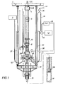
- FIG. 1 is an elevational view of a riser with a telescoping or slip joint, an RCD housing with a RCD shown in phantom, an annular BOP, and a drill string or other tubular in the riser with the drill bit spaced apart from the wellbore, and on the right side of the riser a first T-connector with a first valve attached with a first flexible flow line in fluid communication with an accumulator and a gas supply source through a pressure regulator, and on the left side of the riser a second T-connector with a second valve attached with a second flexible flow line connected with a choke manifold.
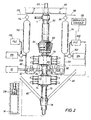
- FIG. 2 is an elevational view of a riser with a telescoping joint, an annular BOP in cut away section showing the annular BOP seal sealing on a tubular, two ram-type BOPs, and a drill string or other tubular in the riser with the drill bit spaced apart from the wellbore, and on the right side of the riser a first T-connector with a first valve attached with a first flexible flow line in fluid communication with a first accumulator and a first gas supply source through a first pressure regulator, and on the left side of the riser a second T-connector with a second valve attached with a second flexible flow line in fluid communication with a second accumulator and a second gas supply source through a second pressure regulator, and a well control choke in fluid communication with the second T-connector.
- FIG. 3 is an elevational view of a riser with a telescoping joint, an RCD housing with a RCD shown in phantom, an annular BOP, and a drill string or other tubular in the riser with the drill bit spaced apart from the wellbore, and on the right side of the riser a first T-connector with a first valve attached with a first flexible flow line in fluid communication with a mud pump with a pressure regulator, a pressure compensation device, and a first trip tank through a pressure relief valve, and on the left side of the riser a second T-connector with a second valve attached with a second flexible flow line in fluid communication with a second trip tank.
- FIG. 4 is an elevational view of a riser with a telescoping joint, an RCD housing with a RCD shown in phantom, an annular BOP, and a drill string or other tubular in the riser with the drill bit spaced apart from the wellbore, and on the right side of the riser a first valve and a flow line in fluid communication with a fluid container shown in cut away section having a fluid container piston, a first conduit shown in cut away section in fluid communication between the fluid container and the riser, and a second conduit in fluid communication between the fluid container and the riser through a second valve.
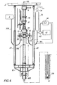
- FIG. 5 is an elevational view of a riser, an RCD in partial cut away section disposed with an RCD housing, and on the right side of the riser a first valve and a flow line in fluid communication with a fluid container shown in cut away section having a fluid container piston and a fluid container conduit with a second valve, and a trip tank conduit in fluid communication with a trip tank.
- FIG. 6 is an elevational view of a riser with an RCD housing with a RCD shown in phantom, an annular BOP, a telescoping or slip joint below the annular BOP, and a drill string or other tubular in the riser with the drill bit in contact with the wellbore, and on the right side of the riser a first T-connector with a first valve attached with a first flexible flow line in fluid communication with an accumulator and a gas supply source through a pressure regulator, and on the left side of the riser a second T-connector with a second valve attached with a second flexible flow line connected with a choke manifold.
- the below systems and methods may be used in many different drilling environments with many different types of floating drilling rigs, including floating semi-submersible rigs, submersible rigs, drill ships, and barge rigs.
- the below systems and methods may be used with MPD, such as with CBHP to maintain a substantially constant BHP, during tripping including drill string connections and disconnections.
- the below systems and methods may also be used with other variations of MPD practiced from floating rigs, such as dual gradient drilling and pressurized mud cap.
- the below systems and methods may be used with conventional drilling, such as when the annular BOP is closed to circulate out a kick or riser gas, and also during the time mud density changes are being made to get the well under control, while the floating rig experiences heaving motion.
- drill bit includes, but is not limited to, any device disposed with a drill string or other tubular for cutting or boring the wellbore.
- riser tensioner members (20, 22) are attached at one end with beam 2 of a floating rig, and at the other end with riser support member or platform 18.
- Beam 2 may be a rotary table beam, but other structural support members on the rig are contemplated for FIG. 1 and for all embodiments shown in all the Figures.
- Riser support member 18 is positioned with riser 16.
- Riser tensioner members (20, 22) may put approximately 2 million pounds of tension on the riser 16 to aid it in dealing with subsea currents, and may advantageously pull down on the floating rig to aid its stability.
- riser tensioner members (20, 22) and riser support member 18 may be used with all embodiments shown in all of the Figures.
- riser tensioner cables connected to a riser tensioner ring disposed with the riser, such as shown in FIGS. 2-5 .
- Riser tensioner members (20, 22) may also be attached with a riser tensioner ring rather than a support member or platform 18.
- marine diverter 4 is attached above riser telescoping joint 6 below the rig beam 2.
- Riser telescoping joint 6, like all the telescoping joints shown in all the Figures, may lengthen or shorten the riser, such as riser 16.
- RCD 10 is disposed in RCD housing 8 over an annular BOP 12.
- the annular BOP 12 is optional.
- a surface ram-type BOP is also optional. There may also be a subsea ram-type BOP and/or a subsea annular BOP, which are not shown.
- RCD housing 8 may be a housing such as the docking station housing in Pub. No. US 2008/0210471 positioned above the surface of the water for latching with an RCD. However, other RCD housings are contemplated, such as the RCD housings disposed in a marine riser proposed in US Pat. Nos. 6,470,975 ; 7,159,669 ; and 7,258,171 .
- the RCD 10 may allow for MPD including, but not limited to, the CBHP variation of MPD.
- Drill string DS is disposed in riser 16 with the drill bit DB spaced apart from the wellbore W, such as when tubular connections are made.
- First T-connector 23 extends from the right side of the riser 16, and first valve 26 is disposed with the first T-connector 23 and fluidly connected with first flexible flow line 30.
- First valve 26 may be remotely actuatable.
- First valve may be in hardwire connection with a PLC 38.
- Sensor 25 may be positioned within first T-connector 23 , as shown in FIG. 1 , or with first valve 26. As shown, sensor 25 may be in hardwire connection with PLC 38.
- Sensor 25 upon sensing a predetermined pressure or pressure range, may transmit a signal to PLC 38 through the hardwire connection or wirelessly to remotely actuate valve 26 to move the valve to the open position and/or the closed position.
- Sensor 25 may measure pressure, although other measurements are also contemplated, such as temperature or flow.
- First flow line 30 may be longer than the flow line or hose to the choke manifold, although other lengths are contemplated.
- a fluid container or gas accumulator 34 is in fluid communication with first flow line 30.
- Accumulator 34 may be any shape or size for containing a compressible gas under pressure, but it is contemplated that a pressure vessel with a greater height than width may be used.
- Accumulator 34 may be a casing closed at both ends, such as a 30 foot (9.1 m) tall casing with 30 inch (76.2 cm) diameter, although other sizes are contemplated.
- a bladder may be used at any liquid and gas interface in the accumulator 34 depending on relative position of the accumulator 34 to the first T-connector 23 and if the accumulator 34 height is substantially the same as the width or if the accumulator width is greater than the height.
- a liquid and gas interface, such as at interface position 5, may be in first flow line 30.
- a vent valve 36 may be disposed with accumulator 34 to allow the movement of vent gas or other fluids through vent line 44.
- a gas source 42 may be in fluid communication with first flow line 30 through a pressure regulator 40. Gas source 42 may provide a compressible gas, such as Nitrogen or air. It is also contemplated that the gas source 42 and/or pressure regulator 40 may be in fluid communication directly with accumulator 34. Pressure regulator 40 may be in hardwire connection with PLC 38. However, pressure regulator 40 may be operated manually, semi-automatically, or automatically to maintain a predetermined pressure. For all embodiments shown in all of the Figures, any connection with a PLC may also be wireless and/or may actively interface with other systems, such as the rig's data collection system and/or MPD choke control systems.
- Second T-connector 24 extends from the left side of the riser 16, and second valve 28 is fluidly connected with the second T-connector 24 and fluidly connected with second flexible flow line 32, which is fluidly connected with choke manifold 3. It is contemplated that other devices besides a choke manifold 3 may be connected with second flow line 32.
- a mirror-image second accumulator, second gas source, and second pressure regulator may be fluidly connected with second flow line 32 similar to what is shown on the right side of the riser 16 in FIG. 1 and on the left side of the riser in FIG. 2 .
- one accumulator, such as accumulator 34 may be fluidly connected with both flow lines (30, 32).
- a redundant system similar to any embodiment shown in any of the Figures or described therewith may be positioned on the left side of the embodiment shown in FIG. 1 .
- accumulator 34, gas source 42, and/or pressure regulator 40 may be positioned on or over the rig floor, above beam 2.
- flow lines (30, 32) may have a diameter of 6 inches (15.2 cm), but other sizes are contemplated. Although flow lines (30, 32) are preferably flexible lines, partial rigid lines are also contemplated with flexible portions.
- First valve 26 and second valve 28 may be hydraulically remotely actuated controlled or operated gate (HCR) valves, although other types of valves are contemplated.
- HCR operated gate
- each of the additional fluid lines may be fluidly connected to T-connectors with valves, such as HCR valves.
- a plurality of riser tensioner cables 80 are attached at one end with a beam 60 of a floating rig, and at the other end with a riser tensioner ring 78.
- Riser tensioner ring 78 is positioned with riser 76.
- Riser tensioner ring 78 and riser tensioner cables 80 may be used with all embodiments shown in all of the Figures.
- Marine diverter 4 is positioned above telescoping joint 62 and below the rig beam 60.
- the non-movable end of telescoping joint 62 is disposed above the annular BOP 64.
- Annular BOP seal 66 is sealed on drill string or tubular DS.
- FIG. 1 there is no RCD in FIG. 2 , since FIG.
- BOP spool 72 is positioned between upper ram-type BOP 70 and lower ram-type BOP 74.
- Other configurations and numbers of ram-type BOPs are contemplated.
- Drill string or tubular DS is shown with the drill bit DB spaced apart from the wellbore W, such as when tubular connections are made.
- First T-connector 82 extends from the right side of the BOP spool 72, and first valve 86 is disposed with the first T-connector 82 and fluidly connected with first flexible flow line or hose 90.
- flexible flow lines are preferred, it is contemplated that partial rigid flow lines may also be used with flexible portions.
- First valve 86 may be remotely actuatable, and it may be in hardwire connection with a PLC 100.
- An operator console 115 may be in hardwire connection with PLC 100. The operator console 115 may be located on the rig for use by rig personnel. A similar operator console may be in hardwire connection with any PLC shown in any of the Figures.
- Sensor 83 may be positioned within first T-connector 82, as shown in FIG.
- sensor 83 may be in hardwire connection with PLC 100. Sensor 83 may measure pressure, although other measurements are also contemplated, such as temperature or flow. Sensor 83, upon sensing a predetermined pressure or pressure range, may transmit a signal to PLC 100 through the hardwire connection or wirelessly to remotely actuate valve 86 to move the valve to the open position and/or the closed position. Additional sensors are contemplated, such as a sensor positioned with second T-connector 84 or second valve 88.
- First flow line 90 may be longer than the flow line or hose to the choke manifold, although other lengths are contemplated.
- a first gas accumulator 94 may be in fluid communication with first flow line 90.
- a first vent valve 96 may be disposed with first accumulator 94 to allow the movement of vent gas or other fluid through first vent line 98.
- a first gas source 104 may be in fluid communication with first flow line 90 through a first pressure regulator 102.
- First gas source 104 may provide a compressible gas, such as nitrogen or air. It is also contemplated that the first gas source 104 and/or pressure regulator 102 may be in fluid communication directly with first accumulator 94.
- First pressure regulator 102 may be in hardwire connection with PLC 100. However, the first pressure regulator 102 may be operated manually, semi-automatically, or automatically to maintain a predetermined pressure.
- Second T-connector 84 extends from the left side of the BOP spool 72, and a second valve 88 is fluidly connected with the second T-connector 84 and fluidly connected with second flexible flow line or hose 92.
- a mirror-image second flow line 92 is fluidly connected with a second accumulator 112, a second gas source 106, a second pressure regulator 108, and a second PLC 110 similar to what is shown on the right side of the riser 76.
- Second vent valve 114 and second vent line 116 are in fluid communication with second accumulator 112. Alternatively, one accumulator may be fluidly connected with both flow lines (90, 92).
- a well control choke 81 such as used to circulate out a well kick, may also be in fluid connection with second T-connector 84. It is contemplated that other devices may be connected with first or second T-connectors (82, 84). First valve 86 and second valve 88 may be hydraulically remotely actuated controlled or operated gate (HCR) valves, although other types of valves are contemplated.
- HCR operated gate
- riser 76 may be a casing type riser or slim riser with a pressure rating of 5000 psi or higher, although other types of risers are contemplated.
- the pressure rating of the system may correspond to that of the riser 76, although the pressure rating of the first flow line 90 and second flow line 92 must also be considered if they are lower than that of the riser 76.
- first accumulator 94, second accumulator 112, first gas source 104, second gas source 106, first pressure regulator 102, and/or second pressure regulator 108 may be positioned on or over the rig floor, such as over beam 60.
- the first valve 26 When drilling using the embodiment shown in FIG. 1 , such as for the CBHP variation of MPD, the first valve 26 is closed.
- the gas accumulator 34 contains a compressible gas, such as nitrogen or air, at a predetermined pressure, such as the desired BHP. Other gases and pressures are contemplated.
- the first valve 26 may have previously been opened and then closed to allow a predetermined amount of drilling fluid, such as the amount a heaving drill string may be anticipated to displace, to enter first flow line 30.
- the amount of liquid allowed to enter the line 30 may be 2 barrels or less. However, other amounts are contemplated.
- the liquid allowed to enter the first flow line 30 will create a liquid and gas interface, preferably in the first flow line 30 in the vertical section to the right of the flow line's catenary, such as at interface position 5 in first flow line 30. Other methods of creating the interface position 5 are contemplated.
- the rig's mud pumps are turned off and the first valve 26 may be opened.
- the rotation of the drill string DS is stopped and the drill string DS is lifted off bottom and suspended from the rig, such as with slips.
- Drill string or tubular DS is shown lifted in FIG. 1 so the drill bit DB is spaced apart from the wellbore W or off bottom, such as when tubular connections are made. If the floating rig has a prior art drill sting heave compensator device, it is no longer operating since the drill bit DB is lifted off bottom. It is otherwise turned off.
- the telescoping joint 6 will telescope, and the inserted drill string tubular will move in harmony with the rig.
- the tubular moves downward, the volume of drilling fluid displaced by the downward movement will flow through first valve 26 into first flow line 30, moving the liquid and gas interface toward the gas accumulator 34.
- the interface may move into the accumulator 34. In either scenario, the liquid volume displaced by the movement of the drill string DS may be accommodated.
- the pressure regulator 40 may be used in conjunction with the gas source 42 to insure that a predetermined pressure of gas is maintained in the first flow line 30 and/or the gas accumulator 34.
- the pressure regulator 40 may be monitored or operated with a PLC 38. However, the pressure regulator 40 may be operated manually, semi-automatically, or automatically.
- a valve that may regulate pressure may be used instead of a pressure regulator. If the pressure regulator 40 or valve is PLC controlled, it may be controlled by an automated choke manifold system, and may be set to be the same as the targeted choke manifold's surface back pressure to be held when the rig's mud pumps are turned off.
- the choke manifold back pressure and matching accumulator gas pressure setting are different values for each bit-off-bottom occasion, and determined by the circulating annular friction pressure while the last stand was drilled. It is contemplated that the values may be adjusted or constant.
- first valve 26 is remotely actuated to a closed position and drilling or rotation of the tubular may resume.
- second valve 28 may remain open for drilling.
- a redundant system may also be used in combination with the first flow line 30 system as discussed above.
- the annular BOP seal 66 When drilling using the embodiment shown in FIG. 2 , for conventional drilling, the annular BOP seal 66 is open during drilling (unlike shown in FIG. 2 ), and the first valve 86 and second valve 88 are closed. To circulate out a kick, the annular BOP seal 66 may be sealed on the drill string or tubular DS as shown in FIG. 2 . The seals in the ram-type BOPs (70, 74) remain open. The rig's mud pumps are turned off. If the floating rig has a prior art drill sting heave compensator device, it is no longer operating since the drill bit is lifted off bottom. It is otherwise turned off. If heave induced pressure fluctuations are anticipated while the seal 66 is sealed, the first valve 86 may be opened.
- a redundant system is attached to second flow line 92 as shown in FIG. 2 , then it may be operated instead of the system attached to the first flow line 90 by keeping first valve 86 closed and opening second valve 88 when annular BOP seal 66 is closed on the drill string DS.
- a redundant system may be used in combination with the system attached with first flow line 30.
- the systems and methods may be used when tripping the drill string out of and returning it to the wellbore.
- the drill bit DB is lifted off bottom, and the same methods may be used as described for when the drill bit DB is lifted off bottom for a drill string connection.
- the systems and methods offer the advantage of allowing for the optimization and/or maximization of tripping speeds by, in effect, cancelling the heave-up and heave down pressure fluctuations otherwise caused by a heaving drill string or other tubular.
- the drill string or other tubular may be moved relative to the riser at a predetermined speed, and that any of the embodiments shown in any of the Figures may be positioned with the riser and operated to substantially eliminate the heave induced pressure fluctuations in the "pressure vessel" so that a substantially constant pressure may be maintained in the annulus between the tubular and the riser while the predetermined speed of the tubular is substantially maintained. Otherwise, a lower or variable tripping speed may need to be used.
- pressure sensors 25, 83, 139, 211, 259 and a respective PLC (38, 100, 155, 219, 248) may be used to monitor pressures, heave-induced fluctuations of those pressures, and their rates of change, among other measurements.
- Actual heave may also be monitored, such as via riser tensioners, such as the riser tensioners (20, 22) shown in FIGS. 1 and 6 , the movement of slip joints, such as the slip joint ( 6 , 62, 124, 204, 280, 302) and/or with GPS. It is contemplated that actual heave may be correlated to measured pressures. For example, in FIG.
- first sensor 25 may measure pressure within first T-connector 23, and the information may be transmitted by a signal to and monitored and processed by a PLC. Additional sensors may be positioned with riser tensioners and/or telescoping slip joints to measure movement related to actual heave. Again, the information may be transmitted by a signal to and monitored and processed by a PLC. The information may be used to remotely open and close first valve 26, such as in FIG. 1 through a signal transmitted from PLC 38 to first valve 26. In addition, all of the information may be used to build and/or update a dynamic computer software model of the system, which model may be used to control the heave compensation system and/or to initiate predictive control, such as by controlling when valves, such a first valve 26 in FIG.
- pressure regulators and pumps such as mud pump 156 with pressure regulator shown in FIG. 3 , or other devices are activated or deactivated.
- the sensing of the drill bit DB off bottom may cause a PLC (38, 100, 155, 219, 248) to open the HCR valve, such as first valve 26 in FIG. 1 .
- the drill string may then be held by spider slips.
- An integrated safety interlock system available from Weatherford International, Inc. of Houston, Texas may be used to prevent inadvertent opening or closing of the spider slips.
- riser tensioner cables 136 are attached at one end with beam 120 of a floating rig, and at the other end with riser tensioner ring 134.
- Beam 120 may be a rotary table beam, but other structural support members on the rig are contemplated.
- Riser tensioner ring 134 is positioned with riser 132 below telescoping joint 124 but above the RCD 126 and T-connectors (138, 140).
- Tensioner ring 134 may be disposed with riser 132 in other locations, such as shown in FIG. 4 .
- diverter 122 is attached above telescoping joint 124 and below the rig beam 120.
- RCD 126 is disposed in RCD housing 128 over annular BOP 130.
- Annular BOP 130 is optional.
- RCD housing 128 may be a housing such as the docking station housing in Pub. No. US 2008/0210471 positioned above the surface of the water for latching with an RCD.
- RCD housings are contemplated, such as the RCD housings disposed in a marine riser proposed in US Pat. Nos. 6,470,975 ; 7,159,669 ; and 7,258,171 .
- the RCD 126 may allow for MPD, including the CBHP variation of MPD.
- a subsea BOP 170 is positioned on the wellhead at the sea floor.
- the subsea BOP 170 may be a ram-type BOP and/or an annular BOP. Although the subsea BOP 170 is only shown in FIG.
- Drill string or tubular DS is disposed in riser 132 and shown lifted so the drill bit DB is spaced apart from the wellbore W, such as when tubular connections are made.
- First T-connector 138 extends from the right side of the riser 132, and first valve 142 is fluidly connected with the first T-connector 138 and fluidly connected with first flexible flow line 146.
- First valve 142 may be remotely actuatable.
- First valve 142 may be in hardwire connection with a PLC 155.
- Sensor 139 may be positioned within first T-connector 138, as shown in FIG. 3 , or with first valve 142.
- Sensor 139 may be in hardwire connection with PLC 155.
- Sensor 139 may measure pressure, although other measurements are also contemplated, such as temperature or flow.
- Sensor 139 may signal PLC 155 through the hardwire connection or wirelessly to remotely actuate valve 142 to move the valve to the open position and/or the closed position.
- First fluid line 146 may be in fluid communication through a four-way mud cross 158 with a mud pump 156 with a pressure regulator, a pressure compensation device 154, and a first trip tank or fluid container 150 through a pressure relief valve 160.
- a pressure regulator that is independent of mud pump 156 may be used.
- First trip tank 150 may be a dedicated trip tank, or an existing trip tank on the rig used for multiple purposes. The pressure regulator may be set at a first predetermined pressure for activation of mud pump 156.
- Pressure compensation device 154 may be adjustable chokes that may be set at a second predetermined pressure to allow fluid to pass.
- Pressure relief valve 160 may be in hardwire connection with PLC 155. However, it may also be operated manually, semi-automatically, or automatically.
- Mud pump 156 may be in fluid communication with a fluid source through mud pump line 180.
- Tank valve 152 may be fluidly connected with tank line 184, and riser valve 162 may be fluidly connected with riser line 164.
- riser line 164 and tank line 184 provide a redundancy, and only one line (164, 184) may preferably be used at a time.
- First valve 142 may be an HCR valve, although other types of valves are contemplated.
- Mud pump 156, tank valve 152, and/or riser valve 162 may each be in hardwire connection with PLC 155.
- Second T-connector 140 extends from the left side of the riser 132, and second valve 144 is fluidly connected with the second T-connector 140 and fluidly connected with second flexible flow line 148, which is fluidly connected with a second trip tank 181, such as a dedicated trip tank, or an existing trip tank on the rig used for multiple purposes. It is also contemplated that there may be only first trip tank 150, and that second flow line 148 may be connected with first trip tank 150. It is also contemplated that instead of second trip tank 181, there may be a MPD drilling choke connected with second flow line 148.
- the MPD drilling choke may be a dedicated choke manifold that is manual, semi-automatic, or automatic. Such an MPD drilling choke is available from Secure Drilling International, L.P. of Houston, Texas, now owned by Weatherford International, Inc.
- Second valve 144 may be remotely actuatable. It is also contemplated that second valve 144 may be a settable overpressure relief valve, or that it may be a rupture disk device that ruptures at a predetermined pressure to allow fluid to pass, such as a predetermined pressure less than the maximum allowable pressure capability of the riser 132. It is also contemplated that for redundancy, a mirror-image configuration identical to that shown on the right side of the riser 132 may also be used on the left side of the riser 132, such as second fluid line 148 being in fluid communication through a second four-way mud cross with a second mud pump, a second pressure compensation device, and a second trip tank through a second pressure relief valve. It is contemplated that mud pump 156, pressure compensation device 154, pressure relief valve 160, first trip tank 150, and/or second trip tank 180 may be positioned on or over the rig floor, such as over beam 120.
- the first valve 142 When drilling using the embodiment shown in FIG. 3 , such as for the CBHP variation of MPD, the first valve 142 is closed. When a connection to the drill string or tubular DS needs to be made, the rig's mud pumps are turned off and the first valve 142 is opened. If a redundant system (not shown in FIG. 3 ) on the left of the riser 132 is going to be used, then the second valve 144 is opened and the first valve 142 is kept closed. The rotation of the drill string DS is stopped and the drill string is lifted off bottom and suspended from the rig, such as with slips. Drill string or tubular DS is shown lifted in FIG. 3 with the drill bit DB spaced apart from the wellbore W or off bottom, such as when tubular connections are made.
- the telescoping joint 124 will telescope, and the inserted drill string or tubular DS will move in harmony with the rig. If the floating rig has a prior art drill sting heave compensator device, it is no longer operating since the drill bit is lifted off bottom. It is otherwise turned off.
- First pressure relief valve 160 may be pre-set to open at a predetermined pressure, such as the same setting as the drill choke manifold during that connection, although other settings are contemplated. At the predetermined pressure, first pressure relief valve 160 allows a volume of fluid to move through it until the pressure of the fluid is less than the predetermined pressure. The downward movement of the tubular will urge the fluid in first flow line 146 past the first pressure relief valve 160.
- tank line 184 and riser line 164 are both present as shown in FIG. 3 , then either tank valve 152 will be open and riser valve 162 will be closed, or riser valve 162 will be open and tank valve 152 will be closed. If tank valve 152 is open, the fluid from line 146 will flow into first trip tank 150. If riser valve 162 is open, then the fluid from line 146 will flow into riser 132 above sealed RCD 126. As can now be understood, riser line 164 and tank line 184 are alternative and redundant lines, and only one line (164, 184) is preferably used at a time, although it is contemplated that both lines (164, 184) may be used simultaneously. As can also now be understood, first trip tank 150 and the riser 132 above sealed RCD 126 both act as fluid containers.
- the mud pump 156 with pressure regulator is activated and moves fluid through the first fluid line 146 and into the riser 132 below the sealed RCD 126.
- the pressure regulator with the mud pump 156 and/or the pressure compensation device 154 may be pre-set at whatever pressure the shut-in manifold surface backpressure target should be during the tubular connection, although other settings are contemplated.
- mud pump 156 may alternatively be in communication with the flow line serving the choke manifold rather than a dedicated flow line such as first flow line 146. It is also contemplated that mud pump 156 may alternatively be the rig's mud kill pump, or a dedicated auxiliary mud pump such as shown in FIG. 3 .
- mud pump 156 may be an auxiliary mud pump such as proposed in the auxiliary pumping systems shown in Figure 1 of US Pat. Nos. 6,352,129 , Figures 2 and 2a of US Pat. No. 6,904,981 , and Figure 5 of 7,044,237 , all of which patents are hereby incorporated by reference for all purposes in their entirety. It is contemplated that mud pump 156 may be used in combination with the auxiliary pumping systems proposed in the '129, '981, and '237 patents. Mud pump 156 may receive fluid through mud pump line 180 from a fluid source, such as first trip tank 150, the rig's drilling fluid source, or a dedicated mud source. When the drill string connection is completed, first valve 142 is closed and rotation of the tubular or drilling may resume.
- a fluid source such as first trip tank 150, the rig's drilling fluid source, or a dedicated mud source.
- FIG. 3 may be positioned with a riser configuration such as shown in FIG. 2 .
- the annular BOP seal 66 may be sealed on the drill string or tubular DS to circulate out a kick. If heave induced pressure fluctuations are anticipated while the seal 66 is sealed, the first valve 142 of FIG. 3 may be opened. The operation of the system is the same as described above for FIG. 3 . If a redundant system is fluidly connected to second flow line 148 (not shown in FIG. 3 ), then it may be operated instead of the system attached to the first flow line 146 by keeping first valve 142 closed and opening second valve 144.
- riser tensioner cables 215 are attached at one end with beam 200 of a floating rig, and at the other end with riser tensioner ring 213.
- Beam 200 may be a rotary table beam, but other structural support members on the rig are contemplated.
- Riser tensioner ring 213 is positioned with riser 216.
- Tensioner ring 213 may be disposed with riser 216 in other locations, such as shown in FIG. 3 .
- marine diverter 202 is disposed above telescoping joint 204 and below rig beam 200.
- RCD 206 is disposed in RCD housing 208 above annular BOP 210.
- Annular BOP 210 is optional. There may also be a surface ram-type BOP, as well as a subsea annular BOP and/or a subsea ram-type BOP.
- RCD housing 208 may be a housing such as the docking station housing proposed in Pub. No. US 2008/0210471 . However, other RCD housings are contemplated, such as the RCD housings disposed in a marine riser proposed in US Pat. Nos. 6,470,975 ; 7,159,669 ; and 7,258,171 .
- the RCD 206 allows for MPD, including the CBHP variation of MPD.
- First T-connector 232 and second T-connector 234 with fluidly connected valves and flow lines are shown extending outwardly from the riser 216. However, they are optional for this embodiment.
- Drill string DS is disposed in riser 216 with drill bit DB spaced apart from the wellbore W, such as when tubular connections are made.
- Flow line 214 with first valve 212 may be fluidly connected with RCD housing 208. It is also contemplated that flow line 214 with first valve 212 may alternatively be fluidly connected below the RCD housing 208 with riser 216 or it components. Flow line 214 may be flexible, rigid, or a combination of flexible and rigid. First valve 212 may be remotely actuatable and in hardwire connection with a PLC 219. Sensor 211 may be positioned within flow line 214, as shown in FIG. 4 , or with first valve 212. Sensor 211 may be in hardwire connection with PLC 219.
- Sensor 211 upon sensing a predetermined pressure or pressure range, may transmit a signal to PLC 219 through the hardwire connection or wirelessly to remotely actuate valve 212 to move the valve to the open position and/or closed position. Sensor 211 may measure pressure, although other measurements are also contemplated, such as temperature or flow. Additional sensors are contemplated.
- a fluid container 217 that is slidably sealed with a fluid container piston 224 may be in fluid communication with flow line 214.
- One end of piston rod 218 may be attached with rig beam 200. It is contemplated that piston rod 218 may alternatively be attached with the floating rig at other locations, or with the movable or inner barrel of the telescoping joint 204, that is in turn attached to the floating rig. It is contemplated that piston rod 218 may have an outside diameter of 3 inches (7.6 cm), although other sizes are contemplated.
- fluid container 217 may have an outside diameter of 10 inches (25.4 cm), although other sizes are contemplated. It is contemplated that the pressure rating of the fluid container 217 may be a multiple of the maximum surface back pressure during connections, such as 3000 psi, although other pressure ratings are contemplated. It is contemplated that the volume capacity of the fluid container 217 may be approximately twice the displaced annulus volume resulting from the drill string or tubular DS at maximum wave heave, such as for example 2.6 barrels (1.3 barrels x 2) assuming a 6 5/8 inch (16.8 cm) diameter drill string and 30 foot (9.1 m) heave (peak to valley and back to peak).
- the height of the fluid container 217 and the length of the piston rod 218 in the fluid container 217 should be greater than the maximum heave distance to insure that the piston 224 remains in the fluid container 217.
- the height of the fluid container 217 may be about the same height as the outer barrel of the slip joint 204.
- the piston rod may be in 10 foot (3 m) threaded sections to accommodate a range of wave heaves.
- the fluid container and piston could be fabricated by The Sheffer Corporation of Cincinnati, Ohio.
- a shearing device such as shear pin 220 may be disposed with piston rod 218 at its connection with rig beam 200 to allow a predetermined location and force shearing of the piston rod 218 from the rig.
- Piston rod 218 may extend through a sealed opening in fluid container cap 236.
- a volume adjustment member 222 may be positioned with piston 224 to compensate for different annulus areas including sizes of tubulars inserted through the riser 216, or different riser sizes, and therefore the different volumes of fluid displaced. Volume adjustment member 222 may be clamped or otherwise positioned with piston rod 218 above piston 224. Drill string or tubular DS is shown lifted with the drill bit spaced apart from the wellbore, such as when tubular connections are made.
- piston rods with different diameters may be used to compensate for different annulus areas including sizes of tubulars inserted through the riser 216 and risers.
- different fluid containers 217 with different volumes such as having the same height but different diameters, may be used to compensate for different diameter tubulars. A smaller tubular diameter may correspond with a smaller fluid container diameter.
- First conduit 226, such as an open flanged spool, provides fluid communication between the fluid container 217 and the riser 216 above the sealed RCD 206.
- Second conduit 228 provides fluid communication between the fluid container 217 and the riser 216 above the sealed RCD 206 through second valve 229.
- Second valve 229 may be remotely actuatable and in hardwire connection with PLC 219.
- Fluid such as drilling fluid, seawater, or water, may be in fluid container 217 above and below piston 224.
- the fluid may be in riser 216 at a fluid level, such as fluid level 230, to insure that there is fluid in fluid container 217 regardless of the position of piston 224.
- First conduit 226 and second conduit 228 may be 10 inches (25.4 cm) in diameter, although other diameters are also contemplated.
- First valve 212 and/or second valve 229 may be HCR valves, although other types of valves are contemplated. Although not shown, it is contemplated that a redundant system may be attached to the left side of riser 216 similar to the system shown on the right side of the riser 216 or similar to any embodiment shown in any of the Figures. It is also contemplated that as an alternative embodiment to FIG. 4 , the fluid container 217 may be positioned on or over the rig floor, such as over rig beam 200. The piston rod 218 would extend upward from the rig, rather than downward as shown in FIG. 4 , and flow line 214 and first and second conduits (226, 228) would need to be longer and preferably flexible.
- riser tensioner cables 274 are attached at one end with beam 240 of a floating rig, and at the other end with riser tensioner brackets 276.
- Riser tensioner brackets 276 are positioned with riser 268.
- Riser tensioner brackets 276 may be disposed with riser 268 in other locations.
- Riser tensioner brackets 276 may be disposed with a riser tensioner ring, such as tensioner ring 213 shown in FIG. 4 .
- RCD 266 is clamped with clamp 270 to RCD housing 272, which is disposed above a telescoping joint 280 and below rig beam 240.
- RCD housing 272 may be a housing such as proposed in Figure 3 of US Pat. No.
- telescoping joint 280 can be locked or unlocked as desired when used with the RCD system in FIG. 5 .
- RCD 266 allows for MPD, including the CBHP variation of MPD.
- Drill string DS is disposed in riser 268. When unlocked, telescoping joint 280 may lengthen or shorten the riser 268 by extending or retracting, respectively.
- Flow line 256 with first valve 258 may be fluidly connected with RCD housing 272. It is also contemplated that flow line 256 with first valve 258 may alternatively be fluidly connected below the RCD housing 272 with riser 268 or any of its components. Flow line 256 may be rigid, flexible, or a combination of flexible and rigid. First valve 258 may be remotely actuatable and in hardwire connection with a PLC 248. Sensor 259 may be positioned within flow line 256, as shown in FIG. 5 , or with first valve 258. Sensor 259 may be in hardwire connection with PLC 248.
- Sensor 259 upon sensing a predetermined pressure or range of pressure, may transmit a signal to PLC 248 through the hardwire connection or wirelessly to remotely actuate valve 258 to move the valve to the open position and/or closed position. Sensor 259 may measure pressure, although other measurements are also contemplated, such as temperature or flow. Additional sensors are contemplated.
- a fluid container 282 that is slidably sealed with a fluid container piston 284 may be in fluid communication with flow line 256.
- One end of piston rod 244 may be attached with rig beam 240. It is contemplated that piston rod 244 may alternatively be attached with the floating rig at other locations, or with the movable or inner barrel of the telescoping joint 280, that is in turn attached to the floating rig. It is contemplated that piston rod 244 may have an outside diameter of 3 inches (7.6 cm), although other sizes are contemplated.
- fluid container 282 may have an outside diameter of 10 inches (25.4 cm), although other sizes are contemplated. It is contemplated that the pressure rating of the fluid container 282 may be a multiple of the maximum surface back pressure during connections, such as 3000 psi, although other pressure ratings are contemplated. It is contemplated that the volume capacity of the fluid container 282 may be approximately twice the displaced annulus volume resulting from the drill string or tubular at maximum wave heave, such as for example 2.6 barrels (1.3 barrels x 2) assuming a 6 5/8 inch (16.8 cm) diameter drill string and 30 foot (9.1 m) heave (peak to valley and back to peak).
- the height of the fluid container 282 and the length of the piston rod 244 in the fluid container 282 should be greater than the maximum heave distance to insure that the piston 284 remains in the fluid container 282.
- the height of the fluid container 282 may be about the same height as the outer barrel of the slip joint 280.
- the piston rod may be in 10 foot (3 m) threaded sections to accommodate a range of wave heaves.
- the fluid container and piston could be fabricated by The Sheffer Corporation of Cincinnati, Ohio.
- a shearing device such as shear pin 242 may be disposed with piston rod 244 at its connection with rig beam 240 to allow a predetermined location and force shearing of the piston rod 244 from the rig.
- Piston rod 244 may extend through a sealed opening in fluid container cap 288.
- a volume adjustment member 286 may be positioned with piston 244 to compensate for different annulus areas including sizes of tubulars inserted through the riser 268, or different riser sizes, and therefore the different volumes of fluid displaced.
- Volume adjustment member 286 may be clamped or otherwise positioned with piston rod 244 above piston 284.
- piston rods with different diameters may be used to compensate for different annulus areas including sizes of tubulars inserted through the riser 268 and risers.
- different fluid containers 282 with different volumes such as having the same height but different diameters, may be used to compensate for different diameter tubulars. A smaller tubular diameter may correspond with a smaller fluid container diameter.
- Fluid container conduit 252 is in fluid communication through second valve 254 between the portion of fluid container 282 above the piston 284 and the portion of fluid container 282 below piston 284. Second valve 254 may be remotely actuatable, and in hardwire connection with PLC 248. Any hardwire connections with a PLC in any of the embodiments in any of the Figures may also be wireless.
- Trip tank conduit 250 is in fluid communication between the fluid container 282 and trip tank 246. Trip tank 246 may be a dedicated trip tank, or it may be an existing trip tank on the rig that may be used for multiple purposes. Trip tank 246 may be located on or over the rig floor, such as over rig beam 240.
- Bracket support member 260 such as a blank flanged spool, may support fluid container 282 from riser 268. Other types of attachment are contemplated.
- Fluid such as drilling fluid, seawater, or water, may be in fluid container 282 above and below piston 284.
- the fluid may be in riser 268 at a sufficient fluid level to insure that there is fluid in fluid container 282 regardless of the position of piston 284.
- the fluid may also be in the trip tank 246 at a sufficient level to insure that there is fluid in fluid container 282 regardless of the position of piston 284.
- Flow line 256 may be 10 inches (25.4 cm) in diameter, although other diameters are also contemplated.
- First valve 258 and/or second valve 254 may be HCR valves, although other types of valves are contemplated.
- a redundant system may be attached to the left side of riser 268 similar to the system shown on the right side of the riser 216 or similar to any embodiment shown in any of the Figures.
- flow hose 264 is fluidly connected with RCD housing 272 through T-connector 262.
- Flow hose 264 may be in fluid communication with the rig's choke manifold, or other devices. It is also contemplated that as an alternative embodiment to FIG.
- the fluid container 282 may be positioned on or over the rig floor, such as over rig beam 240.
- the piston rod 244 would extend upward from the rig, rather than downward as shown in FIG. 5 , and flow line 256 would need to be longer and preferably flexible.
- an alternative embodiment system may be identical with the fluid container 282, piston 284 and trip tank 246 system shown on the right side of riser 268 in FIG. 5 , except that rather than there being a flow line 256 with first valve 258 in fluid communication between the RCD housing 272 and the fluid container 282 as shown in FIG. 5 , there may be a flexible flow line with first valve in fluid communication between the fluid container and the riser below the RCD or annular BOP, such as with one end of the flow line connected to a BOP spool between two ram-type surface BOPs and the other end connected with the side of the fluid container near its top.
- the flow line may connect with the fluid container on the same side as the fluid container conduit, although other locations are contemplated.
- the alternative embodiment would work with any riser configuration shown in any of the Figures.
- the alternative fluid container may be attached with some part of the riser or its components using one or more attachment support members, similar to bracket support member 260 in FIG. 5 . It is also contemplated that riser tensioner members, such as riser tensioner members (20, 22) in FIG. 1 , may be used instead of the tension cables 274 in FIG. 5 .
- the alternative fluid container similar to container 282 in FIG. 5 but with the difference described above, may alternatively be attached to the outer barrel of one of the tensioner members.
- the alternative fluid container with piston system could be used in conventional drilling such as with the riser and annular BOP shown in FIG. 2 , either attached with the riser or its components or attached to a riser tensioner member that may be used instead of riser tension cables.
- the first valve 212 When drilling using the embodiment shown in FIG. 4 , such as for the CBHP variation of MPD, the first valve 212 is closed and the second valve 229 is opened.
- the piston 224 moves fluid into and out of the riser 216 above the RCD 206 through first conduit 226 and second conduit 228.
- the rig's mud pumps are turned off, first valve 212 is opened, and second valve 229 is closed.
- the drill string or tubular DS is lifted off bottom as shown in FIG. 4 and suspended from the rig, such as with slips.
- the telescoping joint 204 will telescope, and the inserted drill string or tubular DS will move in harmony with the rig. If the floating rig has a prior art drill sting or heave compensator device, it is no longer operating since the drill bit is lifted off bottom. It is otherwise turned off.
- the piston 224 connected by piston rod 218 to rig beam 200 will move downward a corresponding distance.
- the volume of fluid displaced by the downward movement of the drill string or tubular will flow through the open first valve 212 through flow line 214 into fluid container 217. Piston 224 will move a corresponding amount of fluid from the portion of fluid container 217 below piston 224 through first conduit 226 into riser 216.
- the piston 224 When the drill string or tubular moves upward, the piston 224, which is connected with the rig beam 200, will also move a corresponding distance upward.
- the piston 224 will displace fluid above it in fluid container 217 through fluid line 214 into riser 216 below RCD 206.
- the amount of fluid displaced by piston 224 desirably corresponds with the amount of fluid displaced by the tubular. Fluid will flow from the riser 216 above the RCD 206 or annular BOP through first conduit 226 into the fluid container 217 below the piston 224.
- a volume adjustment member 222 may be positioned with the piston 224 to compensate for a different diameter tubular.
- a shearing member such as shear pin 220, allows piston rod 218 to be sheared from rig beam 200 in extreme heave conditions, such as hurricane type conditions.
- FIG. 4 may be positioned with a riser configuration such as shown in FIG. 2 .
- the annular BOP seal 66 is sealed on the drill string tubular DS to circulate out a kick. If heave induced pressure fluctuations are anticipated while the seal 66 is sealed, the first valve 212 of FIG. 4 may be opened and the second valve 229 closed.
- the operation of the system is the same as described above for FIG. 4 .
- Other embodiments of FIG. 4 are contemplated, such as the downward movement of a piston moving fluid into the riser annulus below an RCD or annular BOP, and the upward movement of the piston moving fluid out of the riser annulus below an RCD or annular BOP.
- the piston moves in the same direction and the same distance as the tubular, and moves the required amount of fluid into or out of the riser annulus below the RCD or annular BOP.
- the first valve 258 When drilling using the embodiment shown in FIG. 5 , such as for the CBHP variation of MPD with the telescoping joint 280 in the locked position, the first valve 258 is closed and the second valve 254 is opened. The heaving movement of the rig will cause the piston 284 to move fluid through the fluid container conduit 252 and between the fluid container 282 and the trip tank 246.
- the rig's mud pumps When a connection to the drill string or tubular needs to be made, the rig's mud pumps are turned off, first valve 258 is opened, and second valve 254 is closed. The drill string or tubular DS is lifted off bottom and suspended from the rig, such as with slips. If the floating rig has a prior art drill sting or heave compensator device, it is no longer operating since the drill bit is lifted off bottom. It is otherwise turned off.
- the telescoping joint 280 can telescope if in the unlocked position or remains fixed if in the locked position, and, in any case, the inserted drill string or tubular DS will move in harmony with the rig.
- the piston 284 connected by piston rod 244 to rig beam 240 will move downward a corresponding distance.
- the volume of fluid displaced by the downward movement of the drill string or tubular DS will flow through the open first valve 258 through flow line 256 into fluid container 282.
- Piston 284 will move a corresponding amount of fluid from the portion of fluid container 282 below piston 284 through trip tank conduit 250 into trip tank 246.
- the piston 284 When the drill string or tubular moves upward, the piston 284, which is connected with the rig beam 240, will also move a corresponding distance upward.
- the piston 284 will displace fluid above it in fluid container 282 through flow line 256 into RCD housing 272 or riser 268 below RCD 266.
- the amount of fluid displaced by piston 284 desirably corresponds with the amount of fluid displaced by the tubular. Fluid will move from trip tank 246 through trip tank flexible conduit 250 into fluid container 282 below piston 284.
- a volume adjustment member 286 may be positioned with the piston 284 to compensate for a different diameter tubular. It is contemplated that there may be a different volume adjustment member for each tubular size, such as for different diameter drill pipe and risers.
- a shearing member such as shear pin 242 allows piston rod 244 to be sheared from rig beam 240 in extreme heave conditions, such as hurricane type conditions.
- first valve 258 may be closed, second valve 254 opened, the drill string DS lowered so that the drill bit DB is on bottom, the mud pumps turned on, and rotation of the tubular begun so drilling may resume.
- FIG. 5 may be positioned with a riser configuration such as shown in FIG. 2 .
- the annular BOP seal 66 is sealed on the drill string tubular to circulate out a kick. If heave induced pressure fluctuations are anticipated while the seal 66 is sealed, the first valve 258 of FIG. 5 may be opened and the second valve 254 may be closed. The operation of the system is the same as described above for FIG. 5 .
- Other embodiments of FIG. 5 are contemplated, such as the downward movement of a piston moving fluid into the riser annulus below an RCD or annular BOP, and the upward movement of the piston moving fluid out of the riser annulus below an RCD or annular BOP.
- the piston moves in the same direction and the same distance as the tubular, and moves the required amount of fluid into or out of the riser annulus below the RCD or annular BOP.
- the first valve is closed during drilling, and the second valve is opened.
- the heaving movement of the rig will cause the piston to move fluid through the fluid container conduit and between the fluid container and the trip tank.
- the rig's mud pumps are turned off, the first valve is opened, and second valve is closed.
- the drill string or tubular is lifted off bottom and suspended from the rig, such as with slips. The method is otherwise the same as described above for FIG. 5 .
- the drill bit may be on bottom for drilling. Any of the embodiments shown in FIGS. 1-5 may be used to compensate for the change in annulus pressure that would otherwise occur below the RCD 266 due to the lengthening and shortening of the riser 268.
- FIG. 6 is similar to FIG. 1 , except in FIG 6 the telescoping or slip joint 302 is located below the RCD 10 and annular BOP 12, and the drill bit DB is in contact with the wellbore W for drilling.
- the "slip joint piston" embodiment of FIG. 5 is similar to FIG. 6 when the telescoping joint 280, below the RCD 266, is in the unlocked position. When telescoping joint 280 is in the unlocked position, the below method with the drill bit DB on bottom may be used.
- FIG. 1 is shown on the right side of the riser 300 in FIG. 6
- any embodiment shown in any of the Figures may be used with the riser 300 configuration shown in FIG. 6 to compensate for the heave induced pressure fluctuations caused by the telescoping movement of the slip joint 302 while drilling.
- telescoping joint 302 is disposed in the MPD "pressure vessel" in the riser 300 below the RCD 10.
- Marine diverter 4 is disposed below the rig beam 2 and above RCD housing 8.
- RCD 10 is disposed in RCD housing 8 over annular BOP 12.
- the annular BOP 12 is optional.
- a surface ram-type BOP is also optional.
- RCD housing 8 may be a housing such as the docking station housing in Pub. No. US 2008/0210471 ; however, other RCD housings are contemplated, such as the RCD housings disposed in a marine riser proposed in US Pat. Nos. 6,470,975 ; 7,159,669 ; and 7,258,171 .
- the RCD 10 may allow for MPD including, but not limited to, the CBHP variation of MPD.
- Drill string DS is disposed in riser 300 with the drill bit DB in contact with the wellbore W, such as when drilling is occurring.
- First flow line 304 is fluidly connected with accumulator 34, and second flow line 306 is fluidly connected with drilling choke manifold 3.
- first valve 26 When the telescoping joint 302 is heaving, the first valve 26 may be opened, including during drilling with the mud pumps turned on. It is contemplated that first valve 26 may be optional, since the systems and methods may be used both with the drill bit DB in contact with the wellbore W during drilling as shown in FIGS. 5 and 6 when their respective telescoping joint is unlocked or free to extend or retract, and with the drill bit DB spaced apart from the wellbore W during tubular connections or tripping.
- the unlocked telescoping joint 280 of FIG. 5 and/or the telescoping joint 302 of FIG. 6 will telescope.
- the volume of drilling fluid displaced by the riser shortening will flow through first valve 258 in flow line 256 to fluid container 282 of FIG. 5 and/or first valve 26 into first flow line 304 of FIG. 6 moving the liquid and gas interface toward the gas accumulator 34.
- the interface may move into the accumulator 34. In either scenario, the liquid volume displaced by the movement of the telescoping joint may be accommodated.
- FIGS. 1-5 and/or discussed therewith address the cause of the pressure fluctuations when the well is shut in for connections or tripping, or the rig's mud pumps are shut off for other reasons, which is the fluid volumes of the annulus returns that are displaced by the piston effect of the drill string or tubular heaving up and down within the riser and wellbore along with the rig.
- the embodiments shown in FIGS. 1-5 and/or discussed therewith may be used with a riser configuration such as shown in FIGS.
- any redundancy shown in any of the Figures for one embodiment may be used in any other embodiment shown in any of the Figures. It is contemplated that different embodiments may be used together for redundancy, such as for example the system shown in FIG. 1 on one side of the riser, and one of the two redundant systems shown in FIG. 3 on another side of the riser. It should be understood that the systems and methods for all embodiments may be applicable when the drill string is lifted off bottom regardless of the reason, and not just for the making of tubular connections during MPD or to circulate out a kick during conventional drilling.
Abstract
Description
- This invention relates to conventional and/or managed pressure drilling from a floating rig.
- Rotating control devices (RCDs) have been used in the drilling industry for drilling wells. An internal sealing element fixed with an internal rotatable member of the RCD seals around the outside diameter of a tubular and rotates with the tubular. The tubular may be a drill string, casing, coil tubing, or any connected oilfield component. The tubular may be run slidingly through the RCD as the tubular rotates, or when the tubular is not rotating. Examples of some proposed RCDs are shown in
US Pat. Nos. 5,213,158 ;5,647,444 and5,662,181 . - RCDs have been proposed to be positioned with marine risers. An example of a marine riser and some of the associated drilling components is proposed in
U.S. Pat. No. 4,626,135 .US Pat. No. 6,913,092 proposes a seal housing with a RCD positioned above sea level on the upper section of a marine riser to facilitate a mechanically controlled pressurized system.US Pat. No. 7,237,623 proposes a method for drilling from a floating structure using an RCD positioned on a marine riser. Pub. No.US 2008/0210471 proposes a docking station housing positioned above the surface of the water for latching with an RCD.US Pat. Nos. 6,470,975 ;7,159,669 ; and7,258,171 propose positioning an RCD assembly in a housing disposed in a marine riser. An RCD has also been proposed inUS Pat. No. 6,138,774 to be positioned subsea without a marine riser. -
US Pat. Nos. 3,976,148 and4,282,939 proposes methods for determining the flow rate of drilling fluid flowing out of a telescoping marine riser that moves relative to a floating vessel heave.US Pat. No. 4,291,772 proposes a method and apparatus to reduce the tension required on a riser by maintaining a pressure on a lightweight fluid in the riser over the heavier drilling fluid. - Latching assemblies have been proposed in the past for positioning an RCD.
US Pat. No. 7,487,837 proposes a latch assembly for use with a riser for positioning an RCD. Pub. No.US 2006/0144622 proposes a latching system to latch an RCD to a housing. Pub. No.US 2009/0139724 proposes a latch position indicator system for remotely determining whether a latch assembly is latched or unlatched. - In more recent years, RCDs have been used to contain annular fluids under pressure, and thereby manage the pressure within the wellbore relative to the pressure in the surrounding earth formation. In some circumstances, it may be desirable to drill in an underbalanced condition, which facilitates production of formation fluid to the surface of the wellbore since the formation pressure is higher than the wellbore pressure.
US Pat. No. 7,448,454 proposes underbalanced drilling with an RCD. At other times, it may be desirable to drill in an overbalanced condition, which helps to control the well and prevent blowouts since the wellbore pressure is greater than the formation pressure. While Pub. No.US 2006/0157282 generally proposes Managed Pressure Drilling (MPD), International Pub. No.WO 2007/092956 proposes MPD with an RCD. MPD is an adaptive drilling process used to control the annulus pressure profile throughout the wellbore. The objectives are to ascertain the downhole pressure environment limits and to manage the hydraulic annulus pressure profile accordingly. - One equation used in the drilling industry to determine the equivalent weight of the mud and cuttings in the wellbore when circulating with the rig mud pumps on is:

This equation would be changed to conform the units of measurements as needed. In one variation of MPD, the above Circulating Annulus Friction Pressure (AFP), with the rig mud pumps on, is swapped for an increase of surface backpressure, with the rig mud pumps off, resulting in a Constant Bottomhole Pressure (CBHP) variation of MPD, or a constant EMW, whether the mud pumps are circulating or not. Another variation of MPD is proposed inU.S. Pat. No. 7,237,623 for a method where a predetermined column height of heavy viscous mud (most often called kill fluid) is pumped into the annulus. This mud cap controls drilling fluid and cuttings from returning to surface. This pressurized mud cap drilling method is sometimes referred to as bull heading or drilling blind. - The CBHP MPD variation is achieved using non-return valves (e.g., check valves) on the influent or front end of the drill string, an RCD and a pressure regulator, such as a drilling choke valve, on the effluent or back return side of the system. One such drilling choke valve is proposed in
US Pat. No. 4,355,784 . A commercial hydraulically operated choke valve is sold by M-I Swaco of Houston, Texas under the name SUPER AUTOCHOKE. Also, Secure Drilling International, L.P. of Houston, Texas, now owned by Weatherford International, Inc., has developed an electronic operated automatic choke valve that could be used with its underbalanced drilling system proposed inUS Pat. Nos. 7,044,237 ;7,278,496 ;7,367,411 and7,650,950 . In summary, in the past, an operator of a well has used a manual choke valve, a semi-automatic choke valve and/or a fully automatic choke valve for an MPD program. - Generally, the CBHP MPD variation is accomplished with the drilling choke valve open when circulating and the drilling choke valve closed when not circulating. In CBHP MPD, sometimes there is a 10 choke-closing pressure setting when shutting down the rig mud pumps, and a 10 choke-opening setting when starting them up. The mud weight may be changed occasionally as the well is drilled deeper when circulating with the choke valve open so the well does not flow. Surface backpressure, within the available pressure containment capability rating of an RCD, is used when the pumps are turned off (resulting in no AFP) during the making of pipe connections to keep the well from flowing. Also, in a typical CBHP application, the mud weight is reduced by about .5 ppg from conventional drilling mud weight for the similar environment. Applying the above EMW equation, the operator navigates generally within a shifting drilling window, defined by the pore pressure and fracture pressure of the formation, by swapping surface backpressure, for when the pumps are off and the AFP is eliminated, to achieve CBHP.
- The CBHP variation of MPD is uniquely applicable for drilling within narrow drilling windows between the formation pore pressure and fracture pressure by drilling with precise management of the wellbore pressure profile. Its key characteristic is that of maintaining a constant effective bottomhole pressure whether drilling ahead or shut in to make jointed pipe connections. CBHP is practiced with a closed and pressurizable circulating fluids system, which may be viewed as a pressure vessel. When drilling with a hydrostatically underbalanced drilling fluid, a predetermined amount of surface backpressure must be applied via an RCD and choke manifold when the rig's mud pumps are off to make connections.
- While making drill string or other tubular connections on a floating rig, the drill string or other tubular is set on slips with the drill bit lifted off the bottom. The mud pumps are turned off. During such operations, ocean wave heave of the rig may cause the drill string or other tubular to act like a piston moving up and down within the "pressure vessel" in the riser below the RCD, resulting in fluctuations of wellbore pressure that are in harmony with the frequency and magnitude of the rig heave. This can cause surge and swab pressures that will effect the bottom hole pressures and may in turn lead to lost circulation or an influx of formation fluid, particularly in drilling formations with narrow drilling windows. Annulus returns may be displaced by the piston effect of the drill string heaving up and down within the wellbore along with the rig.
- The vertical heave caused by ocean waves that have an average time period of more than 5 seconds have been reported to create surge and swab pressures in the wellbore while the drill string is suspended from the slips. See GROSSO, J.A., "An Analysis of Well Kicks on Offshore Floating Drilling Vessels," SPE 4134, October 1972, pages 1-20, © 1972 Society of Petroleum Engineers. The theoretical surge and swab pressures due to heave motion may be calculated using fluid movement differential equations and average drilling parameters. See BOURGOYNE, JR., ADAM T., et al, "Applied Drilling Engineering," pages 168-171, © 1991 Society of Petroleum Engineers.
- In benign seas of less than a few feet of wave heave, the ability of the CBHP MPD method to maintain a more constant equivalent mud weight is not substantially compromised to a point of non-commerciality. However, in moderate to rough seas, it is desirable that this technology gap be addressed to enable CBHP and other variations of MPD to be practiced in the world's bodies of water where it is most needed, such as deep waters where wave heave may approach 30 feet (9.1 m) or more and where the geologic formations have narrow drilling windows. A vessel or rig heave of 30 feet (peak to valley and back to peak) with a 6 5/8 inch (16.8 cm) diameter drill string may displace about 1.3 barrels of annulus returns on the heave up, and the same amount on heave down. Although the amount of fluid may not appear large, in some wellbore geometries it may cause pressure fluctuations up to 350 psi.
- Studies show that pulling the tubular with a velocity of .5 m/s creates a swab effect of 150 to 300 psi depending on the bottomhole assembly, casing, and drilling fluid configuration. See WAGNER, R.R. et al., "Surge Field Tests Highlight Dynamic Fluid Response," SPE/IADC 25771, February 1993, pages 883-892, © 1993 SPE/IADC Drilling Conference. One deepwater field in the North Sea reportedly faced heave effects between 75 to 150 psi. See SOLVANG, S.A. et al., "Managed Pressure Drilling Resolves Pressure Depletion Related Problems in the Development of the HPHT Kristin Field," SPE/IADC 113672, January 2008, pages 1-9, © 2008 IADC/SPE Managed Pressure Drilling and Underbalanced Operations Conference and Exhibition. However, there are depleted reservoirs and deepwater prospects, such as in the North Sea, offshore Brazil, and elsewhere, where the pressure fluctuation from wave heaving must be lowered to 15 psi to stay within the narrow drilling window between the fracture and the pore pressure gradients. Otherwise, damage to the formation or a well kick or blow out may occur.
- The problem of maintaining a bottomhole pressure (BHP) within acceptable limits in a narrow drilling window when drilling from a heaving Mobile Offshore Drilling Unit (MODU) is discussed in RASMUSSEN, OVLE SUNDE et al, "Evaluation of MPD Methods for Compensation of Surge-and-Swab Pressures in Floating Drilling Operations," IADC/SPE 108346, March 2007, pages 1-11, © 2007 IADC/SPE Managed Pressure Drilling and Underbalanced Operations Conference and Exhibition. One proposed solution when using drilling fluid with density less than the pore pressure gradient is a continuous circulation method in which drilling fluid is continuously circulated through the drill string and the annulus during tripping and drill pipe connection. An identified disadvantage with the method is that the flow rate must be rapidly and continuously adjusted, which is described as likely to be challenging. Otherwise, fracturing or influx is a possibility. Another proposed solution using drilling fluid with density less than the pore pressure gradient is to use an RCD with a choke valve for back pressure control. However, again a rapid system response is required to compensate for the rapid heave motions, which is difficult in moderate to high heave conditions and narrow drilling windows.
- A proposed solution when using drilling fluid with density greater than the pore pressure is a dual gradient drilling fluid system with a subsea mud lift pump, riser, and RCD. Another proposed solution when using drilling fluid with density greater than the pore pressure is a single gradient drilling fluid system with a subsea mud lift pump, riser, and RCD. A disadvantage with both methods is that a rapid response is required at the fluid level interface to compensate for pressure. Subsea mud lift systems utilizing only an adjustable mud/water or mud/air level in the riser will have difficulty controlling surge and swab effects. Another disadvantage is the high cost of a subsea pump operation.
- The authors in the above IADC/SPE 108346 technical paper conclude that given the large heave motion of the MODU (± 2 to 3 m), and the short time between surge and swab pressure peaks (6 to 7 seconds), it may be difficult to achieve complete surge and swab pressure compensation with any of the proposed methods. They suggest that a real-time hydraulics computer model is required to control wellbore pressures during connections and tripping. They propose that the capability of measuring BHP using a wired drill string telemetry system may make equivalent circulating density control easier, but when more accurate control of BHP is required, the computer model will be needed to predict the surge and swab pressure scenarios for the specific conditions. However, such a proposed solution presents a formidable task given the heave intervals of less than 30 seconds, since even programmable logic controller (PLC) controlled chokes consume that amount of time each heave direction to receive measurement while drilling (MWD) data, interpreting it, instructing a choke setting, and then reacting to it.
- International Pub. No.
WO 2009/123476 proposes that a swab pressure may be compensated for by increasing the opening of a subsea bypass choke valve to allow hydrostatic pressure from a subsea lift pump return line to be applied to increase pressure in the borehole, and that a surge pressure may be compensated for by decreasing the opening of the subsea bypass choke valve to allow the subsea lift pump to reduce the pressure in the borehole. The '476 publication admits that compensating for surge and swab pressure is a challenge on a MODU, and it proposes that its method is feasible if given proper measurements of the rig heave motion, and predictive control. However, accurate measurements are difficult to obtain and then respond to, particularly in such a short time frame. Moreover, predictive control is difficult to achieve, since rogue waves or other unusual wave conditions, such as induced by bad weather, cannot be predicted with accuracy.US Pat. No. 5,960,881 proposes a system for reducing surge pressure while running a casing liner. - Wave heave induced pressure fluctuations also occur during tripping the drill string out of and returning it to the wellbore. When surface backpressure is being applied while tripping from a floating rig, such as during deepwater MPD, each heave up is an additive to the tripping out speed, and each heave down is an additive to the tripping in speed. Whether tripping in or out, these heave-related accelerations of the drill string must be considered. Often, the result is slower than desired tripping speeds to avoid surge-swab effects. This can create significant delays, particularly with deepwater rigs commanding rental rates of $500,000 per day.
- The problem of maintaining a substantially constant pressure may also exist in certain applications of conventional drilling with a floating rig. In conventional drilling in deepwater with a marine riser, the riser is not pressurized by mechanical devices during normal operations. The only pressure induced by the rig operator and contained by the riser is that generated by the density of the drilling mud held in the riser (hydrostatic pressure). A typical marine riser is 21¼ inches (54 cm) in diameter and has a maximum pressure rating of 500 psi. However, a high strength riser, such as a 16 inch (40.6 cm) casing with a pressure rating around 5000 psi, known as a slim riser, may be advantageously used in deepwater drilling. A surface BOP may be positioned on such a riser, resulting in lower maintenance and routine stack testing costs.
- To circulate out a kick and also during the time mud density changes are being made to get the well under control, the drill bit is lifted off bottom and the annular BOP closed against the drill string. The annular BOP is typically located over a ram-type BOP. Ram type blow out preventers have also been proposed in the past for drilling operations, such as proposed in
US Pat. Nos. 4,488,703 ;4,508,313 ;4,519,577 ; and5,735,502 . As with annular BOPs, drilling must cease when the internal ram BOP seal is closed or sealed against the drill string, or seal wear will occur. When floating rigs are used, heave induced pressure fluctuations may occur as the drill string or other tubular moves up and down notwithstanding the seal against it from the annular BOP. The annular BOP is often closed for this purpose rather than the ram-type BOP in part because the annular BOP seal inserts can be more easily replaced after becoming worn. The heave induced pressure fluctuations below the annular BOP seal may destabilize an un-cased hole on heave down (surge), and suck in additional influx on heave up (swab). - There appears to be a general consensus that the use of deepwater floating rigs with surface BOPs and slim risers presents a higher risk of the kick coming to surface before a BOP can be closed. With the surface BOP annular seal closed, it sometimes takes hours to circulate out riser gas. Significant heaving on intervals such as 30 seconds (peak to valley and back to peak) may cause or exacerbate many time consuming problems and complications resulting therefrom, such as (1) rubble in the wellbore, (2) out of gauge wellbore, and (3) increased quantities of produced-to-surface hydrocarbons. Wellbore stability may be compromised.
- Drill string motion compensators have been used in the past to maintain constant weight on the drill bit during drilling in spite of oscillation of the floating rig due to wave motion. One such device is a bumper sub, or slack joint, which is used as a component of a drill string, and is placed near the top of the drill collars. A mandrel composing an upper portion of the bumper sub slides in and out of a body of the bumper sub like a telescope in response to the heave of the rig, and this telescopic action of the bumper sub keeps the drill bit stable on the wellbore during drilling. However, a bumper sub only has a maximum 5 foot (1.5 m) stroke range, and its 37 foot (11.3 m) length limits the ability to stack bumper subs in tandem or in triples for use in rough seas.
- Drill string heave compensator devices have been used in the past to decrease the influence of the heave of a floating rig on the drill string when the drill bit is on bottom and the drill string is rotating for drilling. The prior art heave compensators attempt to keep a desired weight on the drill bit while the drill bit is on bottom and drilling. A passive heave compensator known as an in-line compensator may consist of one or more hydraulic cylinders positioned between the traveling block and hook, and may be connected to the deck-mounted air pressure vessels via standpipes and a hose loop, such as the Shaffer Drill String Compensator available from National Oilwell Varco of Houston, Texas.
- The passive heave compensator system typically compensates through hydropneumatic action of compressing a volume of air and throttling of fluid via cylinders and pistons. As the rig heaves up or down, the set air pressure will support the weight corresponding to that pressure. As the drilling gets deeper and more weight is added to the drill string, more pressure needs to be added. A passive crown mounted heave compensator may consist of vertically mounted compression-type cylinders attached to a rigid frame mounted to the derrick water table, such as the Shaffer Crown Mounted Compensator also available from National Oilwell Varco of Houston, Texas. Both the in-line and crown mounted heave compensators use either hydraulic or pneumatic cylinders that act as springs supporting the drill string load, and allow the top of the drill string to remain stationary as the rig heaves. Passive heave compensators may be only about 45% efficient in mild seas, and about 85% efficient in more violent seas, again while the drill bit is on bottom and drilling.
- An active heave compensator may be a hydraulic power assist device to overcome the passive heave compensator seal friction and the drill string guide horn friction. An active system may rely on sensors (such as accelerometers), pumps and a processor that actively interface with the passive heave compensator to maintain the weight needed on the drill bit while on bottom and drilling. An active heave compensator may be used alone, or in combination with a passive heave compensator, again when the drill bit is on bottom and the drill string is rotating for drilling. An active heave compensator is available from National Oilwell Varco of Houston, Texas.
- A downhole motion compensator tool, known as the Subsea Downhole Motion Compensator (SDMC™) available from Weatherford International, Inc. of Houston, Texas, has been successfully used in the past in numerous milling operations. SDMC™ is a trademark of Weatherford International, Inc. See DURST, DOUG et al, "Subsea Downhole Motion Compensator: Field History, Enhancements, and the Next Generation," IADC/SPE 59152, February 2000, pages 1-12, © 2000 Society of Petroleum Engineers Inc. The authors in the above technical paper IADC/SPE 59152 report that although semisubmersible drilling vessels may provide active rig-heave equipment, residual heave is expected when the seas are rough. The authors propose that rig-motion compensators, which operate when the drill bit is drilling, can effectively remove no more than about 90% of heave motion. The SDMC™ motion compensator tool is installed in the work string that is used for critical milling operations, and lands in or on either the wellhead or wear bushing of the wellhead. The tool relies on slackoff weight to activate miniature metering flow regulators that are contained within a piston disposed in a chamber. The tool contains two hydraulic cylinders, with metering devices installed in the piston sections.
US Pat. Nos. 6,039,118 and6,070,670 propose downhole motion compensator tools. - Riser slip joints have been used in the past to compensate for the vertical movement of the floating rig on the riser, such as proposed in
Figure 1 of bothUS Pat. Nos. 4,282,939 and7,237,623 . However, when a riser slip joint is located within the "pressure vessel" in the riser below the RCD, its telescoping movement may result in fluctuations of wellbore pressure much greater than 350 psi that are in harmony with the frequency and magnitude of the rig heave. This creates problems with MPD in formations with narrow drilling windows, particularly with the CBHP variation of MPD. - The above discussed
US Pat. Nos. 3,976,148 ;4,282,939 ;4,291,772 ;4,355,784 ;4,488,703 ;4,508,313 ;4,519,577 ;4,626,135 ;5,213,158 ;5,647,444 ;5,662,181 ;5,735,502 ;5,960,881 ;6,039,118 ;6,070,670 ;6,138,774 ;6,470,975 ;6,913,092 ;7,044,237 ;7,159,669 ;7,237,623 ;7,258,171 ;7,278,496 ;7,367,411 ;7,448,454 ;7,487,837 ; and7,650,950 ; and Pub. Nos.US 2006/0144622 ;2006/0157282; 2008/0210471 2009/0139724 ; and International Pub. Nos.WO 2007/092956 andWO 2009/123476 are all hereby incorporated by reference for all purposes in their entirety.US Patent Nos. 5,647,444 ;5,662,181 ;6,039,118 ;6,070,670 ;6,138,774 ;6,470,975 ;6,913,092 ;7,044,237 ;7,159,669 ;7,237,623 ;7,258,171 ;7,278,496 ;7,367,411 ;7,448,454 and7,487,837 ; and Pub. Nos.US 2006/0144622 ;2006/0157282 ;2008/0210471 ; and2009/0139724 ; and International Pub. No.WO 2007/092956 are assigned to the assignee of the present invention. - The inventors have appreciated that a need exists when drilling from a floating drilling rig for an approach to rapidly compensate for the change in pressure caused by the vertical movement of the drill string or other tubular when the rig's mud pumps are off and the drill string or tubular is lifted off bottom as joint connections are being made, particularly in moderate to rough seas and in geologic formations with narrow drilling windows between pore pressure and fracture pressure. They have also found that a need exists when drilling from floating rigs for an approach to rapidly compensate for the heave induced pressure fluctuations when the rig's mud pumps are off, the drill string or tubular is lifted off bottom, the annular BOP seal is closed, and the drill string or tubular nevertheless continues to move up and down from wave induced heave on the rig while riser gas is circulated out. They have also found that a need exists when tripping the drill string into or out of the hole to optimize tripping speeds by canceling the rig heave-related swab-surge effects. They have also found that a need exists when drilling from floating rigs for an approach to rapidly compensate for the heave induced pressure fluctuations when the rig's mud pumps are on, the drill bit is on bottom with the drill string or tubular rotating during drilling, and a telescoping joint in the riser located below an RCD telescopes from the heaving.
- A system for both conventional and MPD drilling is provided to compensate for heave induced pressure fluctuations on a floating rig when a drill string or other tubular is lifted off bottom and suspended on the rig. When suspended, the tubular moves vertically within a riser, such as when tubular connections are made during MPD, when tripping, or when a gas kick is circulated out during conventional drilling. The system may also be used to compensate for heave induced pressure fluctuations on a floating rig from a telescoping joint located below an RCD when a drill string or other tubular is rotating for drilling. The system may be used to better maintain a substantially constant BHP below an RCD or a closed annular BOP. Advantageously, a method for use of the below system is provided.
- In one embodiment, a valve may be remotely activated to an open position to allow the movement of liquid between the riser annulus below an RCD or annular BOP and a flow line in communication with a gas accumulator containing a pressurized gas. A gas source may be in fluid communication with the flow line and/or the gas accumulator through a gas pressure regulator. A liquid and gas interface preferably in the flow line moves as the tubular moves, allowing liquid to move into and out of the riser annulus to compensate for the vertical movement of the tubular. When the tubular moves up, the interface may move further along the flow line toward the riser. When the tubular moves down, the interface may move further along the flow line toward or into the gas accumulator.
- In another embodiment, a valve may be remotely activated to an open position to allow the liquid in the riser annulus below an RCD or annular BOP to communicate with a flow line. A pressure relief valve or an adjustable choke connected with the flow line may be set at a predetermined pressure. When the tubular moves down and the set pressure is obtained, the pressure relief valve or choke allows the fluid to move through the flow line toward a trip tank. Alternatively, or in addition, the fluid may be allowed to move through the flow line toward the riser above the RCD or annular BOP. When the tubular moves up, a pressure regulator set at a first predetermined pressure allows the mud pump to move fluid along the flow line to the riser annulus below the RCD or annular BOP. A pressure compensation device, such as an adjustable choke, may also be set at a second predetermined pressure and positioned with the flow line to allow fluid to move past it when the second predetermined pressure is reached or exceeded.
- In yet another embodiment, in a slip joint piston method, a first valve may be remotely activated to an open position to allow the liquid in the riser annulus below the RCD or annular BOP to communicate with a flow line. The flow line may be in fluid communication with a fluid container that houses a piston. A piston rod may be attached to the floating rig or the movable barrel of the riser telescoping joint, which is in turn attached to the floating rig. The fluid container may be in fluid communication with the riser annulus above the RCD or annular BOP through a first conduit. The fluid container may also be in fluid communication with the riser annulus above the RCD or annular BOP through a second conduit and second valve. The piston can move in the same direction and the same distance as the tubular to move the required amount of fluid into or out of the riser annulus below the RCD or annular BOP.
- In one embodiment of the slip joint piston method, when the tubular moves down, the piston moves down, moving fluid from the riser annulus located below the RCD or annular BOP into the fluid container. When the tubular heaves up, the piston moves up, moving fluid from the fluid container to the riser annulus located below the RCD or annular BOP. A shear member may be used to allow the piston rod to be sheared from the rig during extreme heave conditions. A volume adjustment member may be positioned with the piston in the fluid container to compensate for different tubular and riser sizes.
- In another embodiment of the slip joint piston method, a first valve may be remotely activated to an open position to allow the liquid in the riser annulus below the RCD or annular BOP to communicate with a flow line. The flow line may be in fluid communication with a fluid container that houses a piston. The piston rod may be attached to the floating rig or the movable barrel of the riser telescoping joint, which is in turn attached to the floating rig. The fluid container may be in fluid communication with a trip tank through a trip tank conduit. The fluid container may have a fluid container conduit with a second valve. The piston can move in the same direction and the same distance as the tubular to move the required amount of fluid into or out of the riser annulus below the RCD or annular BOP.
- Any of the embodiments may be used with a riser having a telescoping joint located below an RCD to compensate for the pressure fluctuations caused by the heaving movement of the telescoping joint when the drill bit is on bottom and drilling. For all of the embodiments, there may be redundancies. Two or more different embodiments may be used together for redundancy. There may be dedicated flow lines, valves, pumps, or other apparatuses for a single function, or there may be shared flow lines, valves, pumps, or apparatuses for different functions.
- Some embodiments of the invention will now be described by way of example only and with reference to the accompanying drawings, in which:
-
FIG. 1 is an elevational view of a riser with a telescoping or slip joint, an RCD housing with a RCD shown in phantom, an annular BOP, and a drill string or other tubular in the riser with the drill bit spaced apart from the wellbore, and on the right side of the riser a first T-connector with a first valve attached with a first flexible flow line in fluid communication with an accumulator and a gas supply source through a pressure regulator, and on the left side of the riser a second T-connector with a second valve attached with a second flexible flow line connected with a choke manifold. -
FIG. 2 is an elevational view of a riser with a telescoping joint, an annular BOP in cut away section showing the annular BOP seal sealing on a tubular, two ram-type BOPs, and a drill string or other tubular in the riser with the drill bit spaced apart from the wellbore, and on the right side of the riser a first T-connector with a first valve attached with a first flexible flow line in fluid communication with a first accumulator and a first gas supply source through a first pressure regulator, and on the left side of the riser a second T-connector with a second valve attached with a second flexible flow line in fluid communication with a second accumulator and a second gas supply source through a second pressure regulator, and a well control choke in fluid communication with the second T-connector. -
FIG. 3 is an elevational view of a riser with a telescoping joint, an RCD housing with a RCD shown in phantom, an annular BOP, and a drill string or other tubular in the riser with the drill bit spaced apart from the wellbore, and on the right side of the riser a first T-connector with a first valve attached with a first flexible flow line in fluid communication with a mud pump with a pressure regulator, a pressure compensation device, and a first trip tank through a pressure relief valve, and on the left side of the riser a second T-connector with a second valve attached with a second flexible flow line in fluid communication with a second trip tank. -
FIG. 4 is an elevational view of a riser with a telescoping joint, an RCD housing with a RCD shown in phantom, an annular BOP, and a drill string or other tubular in the riser with the drill bit spaced apart from the wellbore, and on the right side of the riser a first valve and a flow line in fluid communication with a fluid container shown in cut away section having a fluid container piston, a first conduit shown in cut away section in fluid communication between the fluid container and the riser, and a second conduit in fluid communication between the fluid container and the riser through a second valve. -
FIG. 5 is an elevational view of a riser, an RCD in partial cut away section disposed with an RCD housing, and on the right side of the riser a first valve and a flow line in fluid communication with a fluid container shown in cut away section having a fluid container piston and a fluid container conduit with a second valve, and a trip tank conduit in fluid communication with a trip tank. -
FIG. 6 is an elevational view of a riser with an RCD housing with a RCD shown in phantom, an annular BOP, a telescoping or slip joint below the annular BOP, and a drill string or other tubular in the riser with the drill bit in contact with the wellbore, and on the right side of the riser a first T-connector with a first valve attached with a first flexible flow line in fluid communication with an accumulator and a gas supply source through a pressure regulator, and on the left side of the riser a second T-connector with a second valve attached with a second flexible flow line connected with a choke manifold. - The below systems and methods may be used in many different drilling environments with many different types of floating drilling rigs, including floating semi-submersible rigs, submersible rigs, drill ships, and barge rigs. The below systems and methods may be used with MPD, such as with CBHP to maintain a substantially constant BHP, during tripping including drill string connections and disconnections. The below systems and methods may also be used with other variations of MPD practiced from floating rigs, such as dual gradient drilling and pressurized mud cap. The below systems and methods may be used with conventional drilling, such as when the annular BOP is closed to circulate out a kick or riser gas, and also during the time mud density changes are being made to get the well under control, while the floating rig experiences heaving motion. The more compressible the drilling fluid, the more benefit that will be obtained from the below systems and methods when underbalanced drilling. The below systems and methods may also be used with a riser having a telescoping joint located below an RCD to compensate for the pressure fluctuations caused by the heaving movement of the telescoping joint when the drill bit is in contact with the wellbore and drilling. As used herein, drill bit includes, but is not limited to, any device disposed with a drill string or other tubular for cutting or boring the wellbore.
- Turning to
FIG. 1 , riser tensioner members (20, 22) are attached at one end with beam 2 of a floating rig, and at the other end with riser support member orplatform 18. Beam 2 may be a rotary table beam, but other structural support members on the rig are contemplated forFIG. 1 and for all embodiments shown in all the Figures. There may be a plurality of tensioner members (20, 22) positioned between rig beam 2 andsupport member 18 as is known in the art.Riser support member 18 is positioned withriser 16. Riser tensioner members (20, 22) may put approximately 2 million pounds of tension on theriser 16 to aid it in dealing with subsea currents, and may advantageously pull down on the floating rig to aid its stability. Although only shown inFIG. 1 , riser tensioner members (20, 22) andriser support member 18 may be used with all embodiments shown in all of the Figures. - Other riser tension systems are contemplated for all embodiments shown in all of the Figures, such as riser tensioner cables connected to a riser tensioner ring disposed with the riser, such as shown in
FIGS. 2-5 . Riser tensioner members (20, 22) may also be attached with a riser tensioner ring rather than a support member orplatform 18. Returning toFIG. 1 ,marine diverter 4 is attached above riser telescoping joint 6 below the rig beam 2. Riser telescoping joint 6, like all the telescoping joints shown in all the Figures, may lengthen or shorten the riser, such asriser 16.RCD 10 is disposed inRCD housing 8 over anannular BOP 12. Theannular BOP 12 is optional. A surface ram-type BOP is also optional. There may also be a subsea ram-type BOP and/or a subsea annular BOP, which are not shown.RCD housing 8 may be a housing such as the docking station housing in Pub. No.US 2008/0210471 positioned above the surface of the water for latching with an RCD. However, other RCD housings are contemplated, such as the RCD housings disposed in a marine riser proposed inUS Pat. Nos. 6,470,975 ;7,159,669 ; and7,258,171 . TheRCD 10 may allow for MPD including, but not limited to, the CBHP variation of MPD. Drill string DS is disposed inriser 16 with the drill bit DB spaced apart from the wellbore W, such as when tubular connections are made. - First T-
connector 23 extends from the right side of theriser 16, andfirst valve 26 is disposed with the first T-connector 23 and fluidly connected with firstflexible flow line 30.First valve 26 may be remotely actuatable. First valve may be in hardwire connection with aPLC 38.Sensor 25 may be positioned within first T-connector 23 , as shown inFIG. 1 , or withfirst valve 26. As shown,sensor 25 may be in hardwire connection withPLC 38.Sensor 25, upon sensing a predetermined pressure or pressure range, may transmit a signal toPLC 38 through the hardwire connection or wirelessly to remotely actuatevalve 26 to move the valve to the open position and/or the closed position.Sensor 25 may measure pressure, although other measurements are also contemplated, such as temperature or flow.First flow line 30 may be longer than the flow line or hose to the choke manifold, although other lengths are contemplated. A fluid container orgas accumulator 34 is in fluid communication withfirst flow line 30.Accumulator 34 may be any shape or size for containing a compressible gas under pressure, but it is contemplated that a pressure vessel with a greater height than width may be used.Accumulator 34 may be a casing closed at both ends, such as a 30 foot (9.1 m) tall casing with 30 inch (76.2 cm) diameter, although other sizes are contemplated. It is contemplated that a bladder may be used at any liquid and gas interface in theaccumulator 34 depending on relative position of theaccumulator 34 to the first T-connector 23 and if theaccumulator 34 height is substantially the same as the width or if the accumulator width is greater than the height. A liquid and gas interface, such as atinterface position 5, may be infirst flow line 30. - A
vent valve 36 may be disposed withaccumulator 34 to allow the movement of vent gas or other fluids throughvent line 44. Agas source 42 may be in fluid communication withfirst flow line 30 through apressure regulator 40.Gas source 42 may provide a compressible gas, such as Nitrogen or air. It is also contemplated that thegas source 42 and/orpressure regulator 40 may be in fluid communication directly withaccumulator 34.Pressure regulator 40 may be in hardwire connection withPLC 38. However,pressure regulator 40 may be operated manually, semi-automatically, or automatically to maintain a predetermined pressure. For all embodiments shown in all of the Figures, any connection with a PLC may also be wireless and/or may actively interface with other systems, such as the rig's data collection system and/or MPD choke control systems. Second T-connector 24 extends from the left side of theriser 16, andsecond valve 28 is fluidly connected with the second T-connector 24 and fluidly connected with secondflexible flow line 32, which is fluidly connected withchoke manifold 3. It is contemplated that other devices besides achoke manifold 3 may be connected withsecond flow line 32. - For redundancy, it is contemplated that a mirror-image second accumulator, second gas source, and second pressure regulator may be fluidly connected with
second flow line 32 similar to what is shown on the right side of theriser 16 inFIG. 1 and on the left side of the riser inFIG. 2 . Alternatively, one accumulator, such asaccumulator 34, may be fluidly connected with both flow lines (30, 32). It is also contemplated that a redundant system similar to any embodiment shown in any of the Figures or described therewith may be positioned on the left side of the embodiment shown inFIG. 1 . It is contemplated thataccumulator 34,gas source 42, and/orpressure regulator 40 may be positioned on or over the rig floor, above beam 2. It is contemplated that flow lines (30, 32) may have a diameter of 6 inches (15.2 cm), but other sizes are contemplated. Although flow lines (30, 32) are preferably flexible lines, partial rigid lines are also contemplated with flexible portions.First valve 26 andsecond valve 28 may be hydraulically remotely actuated controlled or operated gate (HCR) valves, although other types of valves are contemplated. - For
FIG. 1 , and for all embodiments shown in all the Figures, there may be additional flexible fluid lines fluidly connected with the T-connectors, such as the first and second T-connectors (23, 24) inFIG. 1 . The additional fluid lines are not shown in any of the Figures for clarity. For example, there may be two additional fluid lines, one of which is redundant, for drilling fluid returns. There may also be an additional fluid line to a trip tank. There may also be an additional fluid line for over-pressure relief. Other additional fluid lines are contemplated. It is contemplated that each of the additional fluid lines may be fluidly connected to T-connectors with valves, such as HCR valves. - In
FIG. 2 , a plurality ofriser tensioner cables 80 are attached at one end with abeam 60 of a floating rig, and at the other end with ariser tensioner ring 78.Riser tensioner ring 78 is positioned withriser 76.Riser tensioner ring 78 andriser tensioner cables 80 may be used with all embodiments shown in all of the Figures.Marine diverter 4 is positioned above telescoping joint 62 and below therig beam 60. The non-movable end of telescoping joint 62 is disposed above theannular BOP 64.Annular BOP seal 66 is sealed on drill string or tubular DS. UnlikeFIG. 1 , there is no RCD inFIG. 2 , sinceFIG. 2 shows a configuration for conventional drilling operations. Although a conventional drilling operation configuration is only shown inFIG. 2 , a similar conventional drilling configuration may be used with all embodiments shown in all of the Figures.BOP spool 72 is positioned between upper ram-type BOP 70 and lower ram-type BOP 74. Other configurations and numbers of ram-type BOPs are contemplated. Drill string or tubular DS is shown with the drill bit DB spaced apart from the wellbore W, such as when tubular connections are made. - First T-
connector 82 extends from the right side of theBOP spool 72, andfirst valve 86 is disposed with the first T-connector 82 and fluidly connected with first flexible flow line orhose 90. Although flexible flow lines are preferred, it is contemplated that partial rigid flow lines may also be used with flexible portions.First valve 86 may be remotely actuatable, and it may be in hardwire connection with aPLC 100. Anoperator console 115 may be in hardwire connection withPLC 100. Theoperator console 115 may be located on the rig for use by rig personnel. A similar operator console may be in hardwire connection with any PLC shown in any of the Figures.Sensor 83 may be positioned within first T-connector 82, as shown inFIG. 2 , or withfirst valve 86. As shown,sensor 83 may be in hardwire connection withPLC 100.Sensor 83 may measure pressure, although other measurements are also contemplated, such as temperature or flow.Sensor 83, upon sensing a predetermined pressure or pressure range, may transmit a signal toPLC 100 through the hardwire connection or wirelessly to remotely actuatevalve 86 to move the valve to the open position and/or the closed position. Additional sensors are contemplated, such as a sensor positioned with second T-connector 84 orsecond valve 88.First flow line 90 may be longer than the flow line or hose to the choke manifold, although other lengths are contemplated. Afirst gas accumulator 94 may be in fluid communication withfirst flow line 90. Afirst vent valve 96 may be disposed withfirst accumulator 94 to allow the movement of vent gas or other fluid throughfirst vent line 98. Afirst gas source 104 may be in fluid communication withfirst flow line 90 through afirst pressure regulator 102.First gas source 104 may provide a compressible gas, such as nitrogen or air. It is also contemplated that thefirst gas source 104 and/orpressure regulator 102 may be in fluid communication directly withfirst accumulator 94.First pressure regulator 102 may be in hardwire connection withPLC 100. However, thefirst pressure regulator 102 may be operated manually, semi-automatically, or automatically to maintain a predetermined pressure. - Second T-
connector 84 extends from the left side of theBOP spool 72, and asecond valve 88 is fluidly connected with the second T-connector 84 and fluidly connected with second flexible flow line orhose 92. For redundancy, a mirror-imagesecond flow line 92 is fluidly connected with asecond accumulator 112, asecond gas source 106, asecond pressure regulator 108, and asecond PLC 110 similar to what is shown on the right side of theriser 76.Second vent valve 114 and second vent line 116 are in fluid communication withsecond accumulator 112. Alternatively, one accumulator may be fluidly connected with both flow lines (90, 92). A well controlchoke 81, such as used to circulate out a well kick, may also be in fluid connection with second T-connector 84. It is contemplated that other devices may be connected with first or second T-connectors (82, 84).First valve 86 andsecond valve 88 may be hydraulically remotely actuated controlled or operated gate (HCR) valves, although other types of valves are contemplated. - It is contemplated that
riser 76 may be a casing type riser or slim riser with a pressure rating of 5000 psi or higher, although other types of risers are contemplated. The pressure rating of the system may correspond to that of theriser 76, although the pressure rating of thefirst flow line 90 andsecond flow line 92 must also be considered if they are lower than that of theriser 76. The use of surface BOPs and slim risers, such as 16 inch (40.6 cm) casing, allows older rigs to drill in deeper water than originally designed because the overall weight to buoy is less, and the rig has deck space for deeper water depths with a slim riser system than it would have available if it were carrying a typical 21 ¼ inch (54 cm) diameter riser with a 500 psi pressure rating. It is contemplated thatfirst accumulator 94,second accumulator 112,first gas source 104,second gas source 106,first pressure regulator 102, and/orsecond pressure regulator 108 may be positioned on or over the rig floor, such as overbeam 60. - When drilling using the embodiment shown in
FIG. 1 , such as for the CBHP variation of MPD, thefirst valve 26 is closed. Thegas accumulator 34 contains a compressible gas, such as nitrogen or air, at a predetermined pressure, such as the desired BHP. Other gases and pressures are contemplated. Thefirst valve 26 may have previously been opened and then closed to allow a predetermined amount of drilling fluid, such as the amount a heaving drill string may be anticipated to displace, to enterfirst flow line 30. The amount of liquid allowed to enter theline 30 may be 2 barrels or less. However, other amounts are contemplated. The liquid allowed to enter thefirst flow line 30 will create a liquid and gas interface, preferably in thefirst flow line 30 in the vertical section to the right of the flow line's catenary, such as atinterface position 5 infirst flow line 30. Other methods of creating theinterface position 5 are contemplated. - When a connection to the drill string DS needs to be made, or when tripping, the rig's mud pumps are turned off and the
first valve 26 may be opened. The rotation of the drill string DS is stopped and the drill string DS is lifted off bottom and suspended from the rig, such as with slips. Drill string or tubular DS is shown lifted inFIG. 1 so the drill bit DB is spaced apart from the wellbore W or off bottom, such as when tubular connections are made. If the floating rig has a prior art drill sting heave compensator device, it is no longer operating since the drill bit DB is lifted off bottom. It is otherwise turned off. As the rig heaves while the drill string connection is being made, the telescoping joint 6 will telescope, and the inserted drill string tubular will move in harmony with the rig. When the tubular moves downward, the volume of drilling fluid displaced by the downward movement will flow throughfirst valve 26 intofirst flow line 30, moving the liquid and gas interface toward thegas accumulator 34. However, the interface may move into theaccumulator 34. In either scenario, the liquid volume displaced by the movement of the drill string DS may be accommodated. - When the tubular moves upward, the pressure of the gas, and the suction or swab created by the tubular in the
riser 16, will cause the liquid and gas interface to move along thefirst flow line 30 toward theriser 16, replacing the volume of drilling fluid moved by the tubular. A substantially equal amount of volume to that previously removed from the annulus is moved back into the annulus. The compressibility of the gas may significantly dampen the pressure fluctuations during connections. For a 6 5/8 inch (16.8 cm) casing and 30 feet (9.1 m) of heave, it is contemplated that approximately 150 cubic feet of gas volume may be needed in theaccumulator 34 andfirst flow line 30, although other amounts are contemplated - The
pressure regulator 40 may be used in conjunction with thegas source 42 to insure that a predetermined pressure of gas is maintained in thefirst flow line 30 and/or thegas accumulator 34. Thepressure regulator 40 may be monitored or operated with aPLC 38. However, thepressure regulator 40 may be operated manually, semi-automatically, or automatically. A valve that may regulate pressure may be used instead of a pressure regulator. If thepressure regulator 40 or valve is PLC controlled, it may be controlled by an automated choke manifold system, and may be set to be the same as the targeted choke manifold's surface back pressure to be held when the rig's mud pumps are turned off. It is contemplated that the choke manifold back pressure and matching accumulator gas pressure setting are different values for each bit-off-bottom occasion, and determined by the circulating annular friction pressure while the last stand was drilled. It is contemplated that the values may be adjusted or constant. - Although the
accumulator vent valve 36 usually remains closed, it may be opened to relieve undesirable pressure sensed in theaccumulator 34. When the drill string connection is completed,first valve 26 is remotely actuated to a closed position and drilling or rotation of the tubular may resume. If a redundant system is connected withsecond flow line 32 as described above, it may be used instead of the system connected withfirst flow line 30, such as by keepingfirst valve 26 closed and openingsecond valve 28 when drill string connections need to be made. It is contemplated thatsecond valve 28 may remain open for drilling. A redundant system may also be used in combination with thefirst flow line 30 system as discussed above. - When drilling using the embodiment shown in
FIG. 2 , for conventional drilling, theannular BOP seal 66 is open during drilling (unlike shown inFIG. 2 ), and thefirst valve 86 andsecond valve 88 are closed. To circulate out a kick, theannular BOP seal 66 may be sealed on the drill string or tubular DS as shown inFIG. 2 . The seals in the ram-type BOPs (70, 74) remain open. The rig's mud pumps are turned off. If the floating rig has a prior art drill sting heave compensator device, it is no longer operating since the drill bit is lifted off bottom. It is otherwise turned off. If heave induced pressure fluctuations are anticipated while theseal 66 is sealed, thefirst valve 86 may be opened. The operation of the system is the same as described above forFIG. 1 . If a redundant system is attached tosecond flow line 92 as shown inFIG. 2 , then it may be operated instead of the system attached to thefirst flow line 90 by keepingfirst valve 86 closed and openingsecond valve 88 whenannular BOP seal 66 is closed on the drill string DS. Alternatively, a redundant system may be used in combination with the system attached withfirst flow line 30. - For all embodiments shown in all of the Figures and/or discussed therewith, it is contemplated that the systems and methods may be used when tripping the drill string out of and returning it to the wellbore. During tripping, the drill bit DB is lifted off bottom, and the same methods may be used as described for when the drill bit DB is lifted off bottom for a drill string connection. The systems and methods offer the advantage of allowing for the optimization and/or maximization of tripping speeds by, in effect, cancelling the heave-up and heave down pressure fluctuations otherwise caused by a heaving drill string or other tubular. It is contemplated that the drill string or other tubular may be moved relative to the riser at a predetermined speed, and that any of the embodiments shown in any of the Figures may be positioned with the riser and operated to substantially eliminate the heave induced pressure fluctuations in the "pressure vessel" so that a substantially constant pressure may be maintained in the annulus between the tubular and the riser while the predetermined speed of the tubular is substantially maintained. Otherwise, a lower or variable tripping speed may need to be used.
- For all embodiments shown in all of the Figures and/or discussed therewith, it is contemplated that pressure sensors (25, 83, 139, 211, 259) and a respective PLC (38, 100, 155, 219, 248) may be used to monitor pressures, heave-induced fluctuations of those pressures, and their rates of change, among other measurements. Actual heave may also be monitored, such as via riser tensioners, such as the riser tensioners (20, 22) shown in
FIGS. 1 and6 , the movement of slip joints, such as the slip joint (6, 62, 124, 204, 280, 302) and/or with GPS. It is contemplated that actual heave may be correlated to measured pressures. For example, inFIG. 1 sensor 25 may measure pressure within first T-connector 23, and the information may be transmitted by a signal to and monitored and processed by a PLC. Additional sensors may be positioned with riser tensioners and/or telescoping slip joints to measure movement related to actual heave. Again, the information may be transmitted by a signal to and monitored and processed by a PLC. The information may be used to remotely open and closefirst valve 26, such as inFIG. 1 through a signal transmitted fromPLC 38 tofirst valve 26. In addition, all of the information may be used to build and/or update a dynamic computer software model of the system, which model may be used to control the heave compensation system and/or to initiate predictive control, such as by controlling when valves, such afirst valve 26 inFIG. 1 , pressure regulators and pumps, such asmud pump 156 with pressure regulator shown inFIG. 3 , or other devices are activated or deactivated. The sensing of the drill bit DB off bottom may cause a PLC (38, 100, 155, 219, 248) to open the HCR valve, such asfirst valve 26 inFIG. 1 . The drill string may then be held by spider slips. An integrated safety interlock system available from Weatherford International, Inc. of Houston, Texas may be used to prevent inadvertent opening or closing of the spider slips. - Turning to
FIG. 3 ,riser tensioner cables 136 are attached at one end withbeam 120 of a floating rig, and at the other end withriser tensioner ring 134.Beam 120 may be a rotary table beam, but other structural support members on the rig are contemplated.Riser tensioner ring 134 is positioned withriser 132 below telescoping joint 124 but above theRCD 126 and T-connectors (138, 140).Tensioner ring 134 may be disposed withriser 132 in other locations, such as shown inFIG. 4 . Returning toFIG. 3 ,diverter 122 is attached above telescoping joint 124 and below therig beam 120.RCD 126 is disposed inRCD housing 128 overannular BOP 130.Annular BOP 130 is optional. -
RCD housing 128 may be a housing such as the docking station housing in Pub. No.US 2008/0210471 positioned above the surface of the water for latching with an RCD. However, other RCD housings are contemplated, such as the RCD housings disposed in a marine riser proposed inUS Pat. Nos. 6,470,975 ;7,159,669 ; and7,258,171 . TheRCD 126 may allow for MPD, including the CBHP variation of MPD. Asubsea BOP 170 is positioned on the wellhead at the sea floor. Thesubsea BOP 170 may be a ram-type BOP and/or an annular BOP. Although thesubsea BOP 170 is only shown inFIG. 3 , it may be used with all embodiments shown in all of the Figures. Drill string or tubular DS is disposed inriser 132 and shown lifted so the drill bit DB is spaced apart from the wellbore W, such as when tubular connections are made. - First T-
connector 138 extends from the right side of theriser 132, andfirst valve 142 is fluidly connected with the first T-connector 138 and fluidly connected with firstflexible flow line 146.First valve 142 may be remotely actuatable.First valve 142 may be in hardwire connection with aPLC 155.Sensor 139 may be positioned within first T-connector 138, as shown inFIG. 3 , or withfirst valve 142.Sensor 139 may be in hardwire connection withPLC 155.Sensor 139 may measure pressure, although other measurements are also contemplated, such as temperature or flow.Sensor 139 may signalPLC 155 through the hardwire connection or wirelessly to remotely actuatevalve 142 to move the valve to the open position and/or the closed position. Additional sensors are contemplated, such as positioned with second T-connector 140 orsecond valve 144. Firstfluid line 146 may be in fluid communication through a four-way mud cross 158 with amud pump 156 with a pressure regulator, apressure compensation device 154, and a first trip tank orfluid container 150 through apressure relief valve 160. Other configurations are contemplated. It is also contemplated that a pressure regulator that is independent ofmud pump 156 may be used.First trip tank 150 may be a dedicated trip tank, or an existing trip tank on the rig used for multiple purposes. The pressure regulator may be set at a first predetermined pressure for activation ofmud pump 156. -
Pressure compensation device 154 may be adjustable chokes that may be set at a second predetermined pressure to allow fluid to pass.Pressure relief valve 160 may be in hardwire connection withPLC 155. However, it may also be operated manually, semi-automatically, or automatically.Mud pump 156 may be in fluid communication with a fluid source throughmud pump line 180.Tank valve 152 may be fluidly connected withtank line 184, andriser valve 162 may be fluidly connected withriser line 164. As will become apparent with the discussion of the method below,riser line 164 andtank line 184 provide a redundancy, and only one line (164, 184) may preferably be used at a time.First valve 142 may be an HCR valve, although other types of valves are contemplated.Mud pump 156,tank valve 152, and/orriser valve 162 may each be in hardwire connection withPLC 155. - Second T-
connector 140 extends from the left side of theriser 132, andsecond valve 144 is fluidly connected with the second T-connector 140 and fluidly connected with secondflexible flow line 148, which is fluidly connected with asecond trip tank 181, such as a dedicated trip tank, or an existing trip tank on the rig used for multiple purposes. It is also contemplated that there may be onlyfirst trip tank 150, and thatsecond flow line 148 may be connected withfirst trip tank 150. It is also contemplated that instead ofsecond trip tank 181, there may be a MPD drilling choke connected withsecond flow line 148. The MPD drilling choke may be a dedicated choke manifold that is manual, semi-automatic, or automatic. Such an MPD drilling choke is available from Secure Drilling International, L.P. of Houston, Texas, now owned by Weatherford International, Inc. -
Second valve 144 may be remotely actuatable. It is also contemplated thatsecond valve 144 may be a settable overpressure relief valve, or that it may be a rupture disk device that ruptures at a predetermined pressure to allow fluid to pass, such as a predetermined pressure less than the maximum allowable pressure capability of theriser 132. It is also contemplated that for redundancy, a mirror-image configuration identical to that shown on the right side of theriser 132 may also be used on the left side of theriser 132, such assecond fluid line 148 being in fluid communication through a second four-way mud cross with a second mud pump, a second pressure compensation device, and a second trip tank through a second pressure relief valve. It is contemplated thatmud pump 156,pressure compensation device 154,pressure relief valve 160,first trip tank 150, and/orsecond trip tank 180 may be positioned on or over the rig floor, such as overbeam 120. - When drilling using the embodiment shown in
FIG. 3 , such as for the CBHP variation of MPD, thefirst valve 142 is closed. When a connection to the drill string or tubular DS needs to be made, the rig's mud pumps are turned off and thefirst valve 142 is opened. If a redundant system (not shown inFIG. 3 ) on the left of theriser 132 is going to be used, then thesecond valve 144 is opened and thefirst valve 142 is kept closed. The rotation of the drill string DS is stopped and the drill string is lifted off bottom and suspended from the rig, such as with slips. Drill string or tubular DS is shown lifted inFIG. 3 with the drill bit DB spaced apart from the wellbore W or off bottom, such as when tubular connections are made. As the rig heaves while the drill string connection is being made, the telescoping joint 124 will telescope, and the inserted drill string or tubular DS will move in harmony with the rig. If the floating rig has a prior art drill sting heave compensator device, it is no longer operating since the drill bit is lifted off bottom. It is otherwise turned off. - Using the system shown to the right of the
riser 132, when the drill string or tubular moves downward, the volume of drilling fluid displaced by the downward movement will flow through the openfirst valve 142 intofirst flow line 146, which contains the same type of drilling fluid or water as is in theriser 132. Firstpressure relief valve 160 may be pre-set to open at a predetermined pressure, such as the same setting as the drill choke manifold during that connection, although other settings are contemplated. At the predetermined pressure, firstpressure relief valve 160 allows a volume of fluid to move through it until the pressure of the fluid is less than the predetermined pressure. The downward movement of the tubular will urge the fluid infirst flow line 146 past the firstpressure relief valve 160. - If
tank line 184 andriser line 164 are both present as shown inFIG. 3 , then eithertank valve 152 will be open andriser valve 162 will be closed, orriser valve 162 will be open andtank valve 152 will be closed. Iftank valve 152 is open, the fluid fromline 146 will flow intofirst trip tank 150. Ifriser valve 162 is open, then the fluid fromline 146 will flow intoriser 132 above sealedRCD 126. As can now be understood,riser line 164 andtank line 184 are alternative and redundant lines, and only one line (164, 184) is preferably used at a time, although it is contemplated that both lines (164, 184) may be used simultaneously. As can also now be understood,first trip tank 150 and theriser 132 above sealedRCD 126 both act as fluid containers. - When the drill string or tubular DS moves upward, the
mud pump 156 with pressure regulator is activated and moves fluid through thefirst fluid line 146 and into theriser 132 below the sealedRCD 126. The pressure regulator with themud pump 156 and/or thepressure compensation device 154 may be pre-set at whatever pressure the shut-in manifold surface backpressure target should be during the tubular connection, although other settings are contemplated. It is contemplated thatmud pump 156 may alternatively be in communication with the flow line serving the choke manifold rather than a dedicated flow line such asfirst flow line 146. It is also contemplated thatmud pump 156 may alternatively be the rig's mud kill pump, or a dedicated auxiliary mud pump such as shown inFIG. 3 . - It is also contemplated that
mud pump 156 may be an auxiliary mud pump such as proposed in the auxiliary pumping systems shown inFigure 1 ofUS Pat. Nos. 6,352,129 ,Figures 2 and 2a ofUS Pat. No. 6,904,981 , andFigure 5 of7,044,237 , all of which patents are hereby incorporated by reference for all purposes in their entirety. It is contemplated thatmud pump 156 may be used in combination with the auxiliary pumping systems proposed in the '129, '981, and '237 patents.Mud pump 156 may receive fluid throughmud pump line 180 from a fluid source, such asfirst trip tank 150, the rig's drilling fluid source, or a dedicated mud source. When the drill string connection is completed,first valve 142 is closed and rotation of the tubular or drilling may resume. - It should be understood that when drilling conventionally, the embodiment shown in
FIG. 3 may be positioned with a riser configuration such as shown inFIG. 2 . Theannular BOP seal 66 may be sealed on the drill string or tubular DS to circulate out a kick. If heave induced pressure fluctuations are anticipated while theseal 66 is sealed, thefirst valve 142 ofFIG. 3 may be opened. The operation of the system is the same as described above forFIG. 3 . If a redundant system is fluidly connected to second flow line 148 (not shown inFIG. 3 ), then it may be operated instead of the system attached to thefirst flow line 146 by keepingfirst valve 142 closed and openingsecond valve 144. - Turning to
FIG. 4 ,riser tensioner cables 215 are attached at one end withbeam 200 of a floating rig, and at the other end withriser tensioner ring 213.Beam 200 may be a rotary table beam, but other structural support members on the rig are contemplated.Riser tensioner ring 213 is positioned withriser 216.Tensioner ring 213 may be disposed withriser 216 in other locations, such as shown inFIG. 3 . Returning toFIG. 4 ,marine diverter 202 is disposed above telescoping joint 204 and belowrig beam 200.RCD 206 is disposed inRCD housing 208 aboveannular BOP 210.Annular BOP 210 is optional. There may also be a surface ram-type BOP, as well as a subsea annular BOP and/or a subsea ram-type BOP. -
RCD housing 208 may be a housing such as the docking station housing proposed in Pub. No.US 2008/0210471 . However, other RCD housings are contemplated, such as the RCD housings disposed in a marine riser proposed inUS Pat. Nos. 6,470,975 ;7,159,669 ; and7,258,171 . TheRCD 206 allows for MPD, including the CBHP variation of MPD. First T-connector 232 and second T-connector 234 with fluidly connected valves and flow lines are shown extending outwardly from theriser 216. However, they are optional for this embodiment. Drill string DS is disposed inriser 216 with drill bit DB spaced apart from the wellbore W, such as when tubular connections are made. -
Flow line 214 withfirst valve 212 may be fluidly connected withRCD housing 208. It is also contemplated thatflow line 214 withfirst valve 212 may alternatively be fluidly connected below theRCD housing 208 withriser 216 or it components.Flow line 214 may be flexible, rigid, or a combination of flexible and rigid.First valve 212 may be remotely actuatable and in hardwire connection with aPLC 219.Sensor 211 may be positioned withinflow line 214, as shown inFIG. 4 , or withfirst valve 212.Sensor 211 may be in hardwire connection withPLC 219.Sensor 211, upon sensing a predetermined pressure or pressure range, may transmit a signal toPLC 219 through the hardwire connection or wirelessly to remotely actuatevalve 212 to move the valve to the open position and/or closed position.Sensor 211 may measure pressure, although other measurements are also contemplated, such as temperature or flow. Additional sensors are contemplated. Afluid container 217 that is slidably sealed with afluid container piston 224 may be in fluid communication withflow line 214. One end ofpiston rod 218 may be attached withrig beam 200. It is contemplated thatpiston rod 218 may alternatively be attached with the floating rig at other locations, or with the movable or inner barrel of the telescoping joint 204, that is in turn attached to the floating rig. It is contemplated thatpiston rod 218 may have an outside diameter of 3 inches (7.6 cm), although other sizes are contemplated. - It is contemplated that
fluid container 217 may have an outside diameter of 10 inches (25.4 cm), although other sizes are contemplated. It is contemplated that the pressure rating of thefluid container 217 may be a multiple of the maximum surface back pressure during connections, such as 3000 psi, although other pressure ratings are contemplated. It is contemplated that the volume capacity of thefluid container 217 may be approximately twice the displaced annulus volume resulting from the drill string or tubular DS at maximum wave heave, such as for example 2.6 barrels (1.3 barrels x 2) assuming a 6 5/8 inch (16.8 cm) diameter drill string and 30 foot (9.1 m) heave (peak to valley and back to peak). The height of thefluid container 217 and the length of thepiston rod 218 in thefluid container 217 should be greater than the maximum heave distance to insure that thepiston 224 remains in thefluid container 217. The height of thefluid container 217 may be about the same height as the outer barrel of the slip joint 204. The piston rod may be in 10 foot (3 m) threaded sections to accommodate a range of wave heaves. The fluid container and piston could be fabricated by The Sheffer Corporation of Cincinnati, Ohio. - A shearing device such as
shear pin 220 may be disposed withpiston rod 218 at its connection withrig beam 200 to allow a predetermined location and force shearing of thepiston rod 218 from the rig. Other shearing methods and systems are contemplated.Piston rod 218 may extend through a sealed opening influid container cap 236. Avolume adjustment member 222 may be positioned withpiston 224 to compensate for different annulus areas including sizes of tubulars inserted through theriser 216, or different riser sizes, and therefore the different volumes of fluid displaced.Volume adjustment member 222 may be clamped or otherwise positioned withpiston rod 218 abovepiston 224. Drill string or tubular DS is shown lifted with the drill bit spaced apart from the wellbore, such as when tubular connections are made. - As an alternative to using a different
volume adjustment member 222 for different tubular sizes, it is contemplated that piston rods with different diameters may be used to compensate for different annulus areas including sizes of tubulars inserted through theriser 216 and risers. As another alternative, it is contemplated that differentfluid containers 217 with different volumes, such as having the same height but different diameters, may be used to compensate for different diameter tubulars. A smaller tubular diameter may correspond with a smaller fluid container diameter. -
First conduit 226, such as an open flanged spool, provides fluid communication between thefluid container 217 and theriser 216 above the sealedRCD 206.Second conduit 228 provides fluid communication between thefluid container 217 and theriser 216 above the sealedRCD 206 throughsecond valve 229.Second valve 229 may be remotely actuatable and in hardwire connection withPLC 219. Fluid, such as drilling fluid, seawater, or water, may be influid container 217 above and belowpiston 224. The fluid may be inriser 216 at a fluid level, such asfluid level 230, to insure that there is fluid influid container 217 regardless of the position ofpiston 224.First conduit 226 andsecond conduit 228 may be 10 inches (25.4 cm) in diameter, although other diameters are also contemplated.First valve 212 and/orsecond valve 229 may be HCR valves, although other types of valves are contemplated. Although not shown, it is contemplated that a redundant system may be attached to the left side ofriser 216 similar to the system shown on the right side of theriser 216 or similar to any embodiment shown in any of the Figures. It is also contemplated that as an alternative embodiment toFIG. 4 , thefluid container 217 may be positioned on or over the rig floor, such as overrig beam 200. Thepiston rod 218 would extend upward from the rig, rather than downward as shown inFIG. 4 , andflow line 214 and first and second conduits (226, 228) would need to be longer and preferably flexible. - Turning to
FIG. 5 ,riser tensioner cables 274 are attached at one end withbeam 240 of a floating rig, and at the other end withriser tensioner brackets 276.Riser tensioner brackets 276 are positioned withriser 268.Riser tensioner brackets 276 may be disposed withriser 268 in other locations.Riser tensioner brackets 276 may be disposed with a riser tensioner ring, such astensioner ring 213 shown inFIG. 4 . Returning toFIG. 5 ,RCD 266 is clamped withclamp 270 toRCD housing 272, which is disposed above a telescoping joint 280 and belowrig beam 240.RCD housing 272 may be a housing such as proposed inFigure 3 ofUS Pat. No. 6,913,092 . As discussed in the '092 patent, telescoping joint 280 can be locked or unlocked as desired when used with the RCD system inFIG. 5 . However, other RCD housings are contemplated. TheRCD 266 allows for MPD, including the CBHP variation of MPD. Drill string DS is disposed inriser 268. When unlocked, telescoping joint 280 may lengthen or shorten theriser 268 by extending or retracting, respectively. -
Flow line 256 withfirst valve 258 may be fluidly connected withRCD housing 272. It is also contemplated thatflow line 256 withfirst valve 258 may alternatively be fluidly connected below theRCD housing 272 withriser 268 or any of its components.Flow line 256 may be rigid, flexible, or a combination of flexible and rigid.First valve 258 may be remotely actuatable and in hardwire connection with aPLC 248.Sensor 259 may be positioned withinflow line 256, as shown inFIG. 5 , or withfirst valve 258.Sensor 259 may be in hardwire connection withPLC 248.Sensor 259, upon sensing a predetermined pressure or range of pressure, may transmit a signal toPLC 248 through the hardwire connection or wirelessly to remotely actuatevalve 258 to move the valve to the open position and/or closed position.Sensor 259 may measure pressure, although other measurements are also contemplated, such as temperature or flow. Additional sensors are contemplated. Afluid container 282 that is slidably sealed with afluid container piston 284 may be in fluid communication withflow line 256. One end ofpiston rod 244 may be attached withrig beam 240. It is contemplated thatpiston rod 244 may alternatively be attached with the floating rig at other locations, or with the movable or inner barrel of the telescoping joint 280, that is in turn attached to the floating rig. It is contemplated thatpiston rod 244 may have an outside diameter of 3 inches (7.6 cm), although other sizes are contemplated. - It is contemplated that
fluid container 282 may have an outside diameter of 10 inches (25.4 cm), although other sizes are contemplated. It is contemplated that the pressure rating of thefluid container 282 may be a multiple of the maximum surface back pressure during connections, such as 3000 psi, although other pressure ratings are contemplated. It is contemplated that the volume capacity of thefluid container 282 may be approximately twice the displaced annulus volume resulting from the drill string or tubular at maximum wave heave, such as for example 2.6 barrels (1.3 barrels x 2) assuming a 6 5/8 inch (16.8 cm) diameter drill string and 30 foot (9.1 m) heave (peak to valley and back to peak). The height of thefluid container 282 and the length of thepiston rod 244 in thefluid container 282 should be greater than the maximum heave distance to insure that thepiston 284 remains in thefluid container 282. The height of thefluid container 282 may be about the same height as the outer barrel of the slip joint 280. The piston rod may be in 10 foot (3 m) threaded sections to accommodate a range of wave heaves. The fluid container and piston could be fabricated by The Sheffer Corporation of Cincinnati, Ohio. - A shearing device such as
shear pin 242 may be disposed withpiston rod 244 at its connection withrig beam 240 to allow a predetermined location and force shearing of thepiston rod 244 from the rig. Other shearing methods and systems are contemplated.Piston rod 244 may extend through a sealed opening influid container cap 288. Avolume adjustment member 286 may be positioned withpiston 244 to compensate for different annulus areas including sizes of tubulars inserted through theriser 268, or different riser sizes, and therefore the different volumes of fluid displaced. -
Volume adjustment member 286 may be clamped or otherwise positioned withpiston rod 244 abovepiston 284. As an alternative to using a differentvolume adjustment member 286 for different tubular sizes, it is contemplated that piston rods with different diameters may be used to compensate for different annulus areas including sizes of tubulars inserted through theriser 268 and risers. As another alternative, it is contemplated that differentfluid containers 282 with different volumes, such as having the same height but different diameters, may be used to compensate for different diameter tubulars. A smaller tubular diameter may correspond with a smaller fluid container diameter. -
Fluid container conduit 252 is in fluid communication throughsecond valve 254 between the portion offluid container 282 above thepiston 284 and the portion offluid container 282 belowpiston 284.Second valve 254 may be remotely actuatable, and in hardwire connection withPLC 248. Any hardwire connections with a PLC in any of the embodiments in any of the Figures may also be wireless.Trip tank conduit 250 is in fluid communication between thefluid container 282 andtrip tank 246.Trip tank 246 may be a dedicated trip tank, or it may be an existing trip tank on the rig that may be used for multiple purposes.Trip tank 246 may be located on or over the rig floor, such as overrig beam 240.Bracket support member 260, such as a blank flanged spool, may supportfluid container 282 fromriser 268. Other types of attachment are contemplated. Fluid, such as drilling fluid, seawater, or water, may be influid container 282 above and belowpiston 284. The fluid may be inriser 268 at a sufficient fluid level to insure that there is fluid influid container 282 regardless of the position ofpiston 284. The fluid may also be in thetrip tank 246 at a sufficient level to insure that there is fluid influid container 282 regardless of the position ofpiston 284. -
Flow line 256 may be 10 inches (25.4 cm) in diameter, although other diameters are also contemplated.First valve 258 and/orsecond valve 254 may be HCR valves, although other types of valves are contemplated. Although not shown, it is contemplated that a redundant system may be attached to the left side ofriser 268 similar to the system shown on the right side of theriser 216 or similar to any embodiment shown in any of the Figures. On the left side ofriser 268,flow hose 264 is fluidly connected withRCD housing 272 through T-connector 262.Flow hose 264 may be in fluid communication with the rig's choke manifold, or other devices. It is also contemplated that as an alternative embodiment toFIG. 5 , thefluid container 282 may be positioned on or over the rig floor, such as overrig beam 240. Thepiston rod 244 would extend upward from the rig, rather than downward as shown inFIG. 5 , andflow line 256 would need to be longer and preferably flexible. - As another alternative to
FIG. 5 , an alternative embodiment system may be identical with thefluid container 282,piston 284 andtrip tank 246 system shown on the right side ofriser 268 inFIG. 5 , except that rather than there being aflow line 256 withfirst valve 258 in fluid communication between theRCD housing 272 and thefluid container 282 as shown inFIG. 5 , there may be a flexible flow line with first valve in fluid communication between the fluid container and the riser below the RCD or annular BOP, such as with one end of the flow line connected to a BOP spool between two ram-type surface BOPs and the other end connected with the side of the fluid container near its top. The flow line may connect with the fluid container on the same side as the fluid container conduit, although other locations are contemplated. The alternative embodiment would work with any riser configuration shown in any of the Figures. - The alternative fluid container may be attached with some part of the riser or its components using one or more attachment support members, similar to
bracket support member 260 inFIG. 5 . It is also contemplated that riser tensioner members, such as riser tensioner members (20, 22) inFIG. 1 , may be used instead of thetension cables 274 inFIG. 5 . The alternative fluid container, similar tocontainer 282 inFIG. 5 but with the difference described above, may alternatively be attached to the outer barrel of one of the tensioner members. As another alternative embodiment, the alternative fluid container with piston system could be used in conventional drilling such as with the riser and annular BOP shown inFIG. 2 , either attached with the riser or its components or attached to a riser tensioner member that may be used instead of riser tension cables. - When drilling using the embodiment shown in
FIG. 4 , such as for the CBHP variation of MPD, thefirst valve 212 is closed and thesecond valve 229 is opened. When the rig heaves while the drill bit DB is on bottom and the drill string DS is rotating during drilling, thepiston 224 moves fluid into and out of theriser 216 above theRCD 206 throughfirst conduit 226 andsecond conduit 228. When a connection to the drill string or tubular needs to be made, the rig's mud pumps are turned off,first valve 212 is opened, andsecond valve 229 is closed. The drill string or tubular DS is lifted off bottom as shown inFIG. 4 and suspended from the rig, such as with slips. - As the rig heaves while the drill string or tubular connection is being made, the telescoping joint 204 will telescope, and the inserted drill string or tubular DS will move in harmony with the rig. If the floating rig has a prior art drill sting or heave compensator device, it is no longer operating since the drill bit is lifted off bottom. It is otherwise turned off. When the drill string or tubular DS moves downward, the
piston 224 connected bypiston rod 218 to rigbeam 200 will move downward a corresponding distance. The volume of fluid displaced by the downward movement of the drill string or tubular will flow through the openfirst valve 212 throughflow line 214 intofluid container 217.Piston 224 will move a corresponding amount of fluid from the portion offluid container 217 belowpiston 224 throughfirst conduit 226 intoriser 216. - When the drill string or tubular moves upward, the
piston 224, which is connected with therig beam 200, will also move a corresponding distance upward. Thepiston 224 will displace fluid above it influid container 217 throughfluid line 214 intoriser 216 belowRCD 206. The amount of fluid displaced bypiston 224 desirably corresponds with the amount of fluid displaced by the tubular. Fluid will flow from theriser 216 above theRCD 206 or annular BOP throughfirst conduit 226 into thefluid container 217 below thepiston 224. Avolume adjustment member 222 may be positioned with thepiston 224 to compensate for a different diameter tubular. - It is contemplated that there may be a different volume adjustment member for each tubular size, such as for different diameter drill pipe and risers. A shearing member, such as
shear pin 220, allowspiston rod 218 to be sheared fromrig beam 200 in extreme heave conditions, such as hurricane type conditions. When the drill string or tubular connection is completed, thefirst valve 212 may be closed, thesecond valve 229 opened, the drill string DS lowered so that the drill bit is on bottom, the mud pumps turned on, and rotation of the tubular begun so drilling may resume. - It should be understood that when drilling conventionally, the embodiment shown in
FIG. 4 may be positioned with a riser configuration such as shown inFIG. 2 . Theannular BOP seal 66 is sealed on the drill string tubular DS to circulate out a kick. If heave induced pressure fluctuations are anticipated while theseal 66 is sealed, thefirst valve 212 ofFIG. 4 may be opened and thesecond valve 229 closed. The operation of the system is the same as described above forFIG. 4 . Other embodiments ofFIG. 4 are contemplated, such as the downward movement of a piston moving fluid into the riser annulus below an RCD or annular BOP, and the upward movement of the piston moving fluid out of the riser annulus below an RCD or annular BOP. The piston moves in the same direction and the same distance as the tubular, and moves the required amount of fluid into or out of the riser annulus below the RCD or annular BOP. - When drilling using the embodiment shown in
FIG. 5 , such as for the CBHP variation of MPD with the telescoping joint 280 in the locked position, thefirst valve 258 is closed and thesecond valve 254 is opened. The heaving movement of the rig will cause thepiston 284 to move fluid through thefluid container conduit 252 and between thefluid container 282 and thetrip tank 246. When a connection to the drill string or tubular needs to be made, the rig's mud pumps are turned off,first valve 258 is opened, andsecond valve 254 is closed. The drill string or tubular DS is lifted off bottom and suspended from the rig, such as with slips. If the floating rig has a prior art drill sting or heave compensator device, it is no longer operating since the drill bit is lifted off bottom. It is otherwise turned off. - As the rig heaves while the drill string or tubular connection is being made, the telescoping joint 280 can telescope if in the unlocked position or remains fixed if in the locked position, and, in any case, the inserted drill string or tubular DS will move in harmony with the rig. When the drill string or tubular moves downward, the
piston 284 connected bypiston rod 244 to rigbeam 240 will move downward a corresponding distance. The volume of fluid displaced by the downward movement of the drill string or tubular DS will flow through the openfirst valve 258 throughflow line 256 intofluid container 282.Piston 284 will move a corresponding amount of fluid from the portion offluid container 282 belowpiston 284 throughtrip tank conduit 250 intotrip tank 246. - When the drill string or tubular moves upward, the
piston 284, which is connected with therig beam 240, will also move a corresponding distance upward. Thepiston 284 will displace fluid above it influid container 282 throughflow line 256 intoRCD housing 272 orriser 268 belowRCD 266. The amount of fluid displaced bypiston 284 desirably corresponds with the amount of fluid displaced by the tubular. Fluid will move fromtrip tank 246 through trip tankflexible conduit 250 intofluid container 282 belowpiston 284. Avolume adjustment member 286 may be positioned with thepiston 284 to compensate for a different diameter tubular. It is contemplated that there may be a different volume adjustment member for each tubular size, such as for different diameter drill pipe and risers. - A shearing member, such as
shear pin 242, allowspiston rod 244 to be sheared fromrig beam 240 in extreme heave conditions, such as hurricane type conditions. When the drill string or tubular connection is completed,first valve 258 may be closed,second valve 254 opened, the drill string DS lowered so that the drill bit DB is on bottom, the mud pumps turned on, and rotation of the tubular begun so drilling may resume. - It should be understood that when drilling conventionally, the embodiment shown in
FIG. 5 may be positioned with a riser configuration such as shown inFIG. 2 . Theannular BOP seal 66 is sealed on the drill string tubular to circulate out a kick. If heave induced pressure fluctuations are anticipated while theseal 66 is sealed, thefirst valve 258 ofFIG. 5 may be opened and thesecond valve 254 may be closed. The operation of the system is the same as described above forFIG. 5 . Other embodiments ofFIG. 5 are contemplated, such as the downward movement of a piston moving fluid into the riser annulus below an RCD or annular BOP, and the upward movement of the piston moving fluid out of the riser annulus below an RCD or annular BOP. The piston moves in the same direction and the same distance as the tubular, and moves the required amount of fluid into or out of the riser annulus below the RCD or annular BOP. - For the alternative embodiment to
FIG. 5 described above having a flow line with valve between the fluid container and the riser below the RCD or annular BOP, and fluid container mounted to the riser or its components or to the outer barrel of a riser tensioner member, such as riser tensioner members (20, 22) inFIG. 1 , the first valve is closed during drilling, and the second valve is opened. The heaving movement of the rig will cause the piston to move fluid through the fluid container conduit and between the fluid container and the trip tank. When a connection to the drill string or tubular needs to be made, the rig's mud pumps are turned off, the first valve is opened, and second valve is closed. The drill string or tubular is lifted off bottom and suspended from the rig, such as with slips. The method is otherwise the same as described above forFIG. 5 . - As will be discussed below in conjunction with
FIG. 6 , when thetelescoping joint 280 ofFIG. 5 is unlocked and allowed to extend and retract, the drill bit may be on bottom for drilling. Any of the embodiments shown inFIGS. 1-5 may be used to compensate for the change in annulus pressure that would otherwise occur below theRCD 266 due to the lengthening and shortening of theriser 268. -
FIG. 6 is similar toFIG. 1 , except inFIG 6 the telescoping or slip joint 302 is located below theRCD 10 andannular BOP 12, and the drill bit DB is in contact with the wellbore W for drilling. The "slip joint piston" embodiment ofFIG. 5 is similar toFIG. 6 when the telescoping joint 280, below theRCD 266, is in the unlocked position. When telescoping joint 280 is in the unlocked position, the below method with the drill bit DB on bottom may be used. Although the embodiment fromFIG. 1 is shown on the right side of theriser 300 inFIG. 6 , any embodiment shown in any of the Figures may be used with theriser 300 configuration shown inFIG. 6 to compensate for the heave induced pressure fluctuations caused by the telescoping movement of the slip joint 302 while drilling. As can be understood, telescoping joint 302 is disposed in the MPD "pressure vessel" in theriser 300 below theRCD 10. -
Marine diverter 4 is disposed below the rig beam 2 and aboveRCD housing 8.RCD 10 is disposed inRCD housing 8 overannular BOP 12. Theannular BOP 12 is optional. A surface ram-type BOP is also optional. There may also be a subsea ram-type BOP and/or a subsea annular BOP, which are not shown, but were discussed above and illustrated inFIG. 3 .RCD housing 8 may be a housing such as the docking station housing in Pub. No.US 2008/0210471 ; however, other RCD housings are contemplated, such as the RCD housings disposed in a marine riser proposed inUS Pat. Nos. 6,470,975 ;7,159,669 ; and7,258,171 . TheRCD 10 may allow for MPD including, but not limited to, the CBHP variation of MPD. Drill string DS is disposed inriser 300 with the drill bit DB in contact with the wellbore W, such as when drilling is occurring.First flow line 304 is fluidly connected withaccumulator 34, andsecond flow line 306 is fluidly connected withdrilling choke manifold 3. - The methods described above for each of the embodiments shown in any of the Figures may be used with the
riser 300 configuration shown inFIG. 6 . When the telescoping joint 302 is heaving, thefirst valve 26 may be opened, including during drilling with the mud pumps turned on. It is contemplated thatfirst valve 26 may be optional, since the systems and methods may be used both with the drill bit DB in contact with the wellbore W during drilling as shown inFIGS. 5 and6 when their respective telescoping joint is unlocked or free to extend or retract, and with the drill bit DB spaced apart from the wellbore W during tubular connections or tripping. - As the rig heaves while the drill bit DB is drilling, the
unlocked telescoping joint 280 ofFIG. 5 and/or thetelescoping joint 302 ofFIG. 6 will telescope. When the rig heaves downward and the telescoping joint retracts, or shortens the riser, the volume of drilling fluid displaced by the riser shortening will flow throughfirst valve 258 inflow line 256 tofluid container 282 ofFIG. 5 and/orfirst valve 26 intofirst flow line 304 ofFIG. 6 moving the liquid and gas interface toward thegas accumulator 34. However, the interface may move into theaccumulator 34. In either scenario, the liquid volume displaced by the movement of the telescoping joint may be accommodated. - In
FIG. 5 , when theunlocked telescoping joint 280 extends, or lengthens theriser 268, thepiston 284 moves upward influid container 282, moving fluid throughflow line 256 into theriser 268. InFIG. 6 , when the telescoping joint 302 extends, or lengthens theriser 300, the pressure of the gas, and the suction caused by the movement of the telescoping joint 302, will cause the liquid and gas interface to move along thefirst flow line 304 toward theriser 300, adding a volume of drilling fluid to theriser 300. A substantially equal amount of volume to that previously removed from the annulus is moved back into the annulus. - As can now be understood, all embodiments shown in
FIGS. 1-5 and/or discussed therewith address the cause of the pressure fluctuations when the well is shut in for connections or tripping, or the rig's mud pumps are shut off for other reasons, which is the fluid volumes of the annulus returns that are displaced by the piston effect of the drill string or tubular heaving up and down within the riser and wellbore along with the rig. Further, the embodiments shown inFIGS. 1-5 and/or discussed therewith may be used with a riser configuration such as shown inFIGS. 5 and6 , with a riser telescoping joint located below an RCD, to address the cause of the pressure fluctuations when drilling is occurring and the rig's mud pumps are on, which is the fluid volumes of the annulus returns that are displaced by the telescoping movement of the telescoping joint heaving up and down along with the rig. - Any redundancy shown in any of the Figures for one embodiment may be used in any other embodiment shown in any of the Figures. It is contemplated that different embodiments may be used together for redundancy, such as for example the system shown in
FIG. 1 on one side of the riser, and one of the two redundant systems shown inFIG. 3 on another side of the riser. It should be understood that the systems and methods for all embodiments may be applicable when the drill string is lifted off bottom regardless of the reason, and not just for the making of tubular connections during MPD or to circulate out a kick during conventional drilling. - The foregoing disclosure and description of the invention are illustrative and explanatory thereof, and various changes in the details of the illustrated apparatus and system, and the construction and method of operation may be made without departing from the spirit of the invention.
- The invention can also be defined by the following numbered clauses.
- 1. A system for managing pressure from a floating rig heaving relative to an ocean floor, comprising:
- a riser in communication with a wellbore and extending from the ocean floor;
- a tubular suspended from the floating rig and heaving within said riser;
- an annulus formed between said tubular and said riser;
- a drill bit disposed with said tubular, wherein said drill bit is spaced apart from said wellbore;
- a fluid container for receiving a volume of a fluid when said tubular heaving in said riser toward said wellbore;
- a line for communicating said annulus with said first fluid container; and
- a first valve in said line movable between a closed position when said drill bit is contacting said wellbore and an open position when said drill bit is spaced apart from said wellbore to manage pressure from the floating rig heaving relative to the ocean floor.
- 2. The system of clause 1, further comprising an annular blowout preventer having a seal, said annular blowout preventer seal movable between an open position and a sealing position on said tubular, wherein when said annular blowout preventer seal is in said sealing position on said tubular, said first valve is in said open position to manage pressure from the floating rig heaving relative to the ocean floor.
- 3. The system of clause 1, wherein said first fluid container is an accumulator, and said line and said accumulator are regulated to maintain a predetermined pressure.
- 4. The system of
clause 3, wherein said line comprising a flexible flow line and wherein said fluid in said accumulator is a gas and the fluid in said annulus is a liquid and said gas and said liquid interface is in said flexible flow line. - 5. The system of
clause 4, wherein said accumulator gas providing a volume of liquid to said annulus when said tubular heaving from said wellbore. - 6. The system of clause 1, further comprising:
- a programmable controller; and
- a sensor for transmitting a signal to said programmable controller;
- wherein said first valve remotely actuatable and controllable by said programmable controller in response to said sensor transmitted signal.
- 7. The system of clause 1, wherein said fluid container is a trip tank.
- 8. The system of clause 1, further comprising a pressure relief valve, said pressure relief valve allows said volume of fluid to be received in said fluid container.
- 9. The system of
clause 8, further comprising a mud pump and a pressure regulator to provide said volume of fluid through said line to said annulus. - 10. The system of clause 1 wherein said fluid container being a cylinder, said cylinder having a piston.
- 11. The system of
clause 10, further comprising a piston rod connected between said piston and the floating rig. - 12. The system of
clause 10, further comprising a first conduit, said first conduit communicating said fluid from said cylinder. - 13. The system of
clause 12, further comprising a second valve in fluid communication with said first conduit and movable being an open position when said drill bit is contacting said wellbore and a closed position when said drill bit is spaced apart from said wellbore. - 14. The system of clause 13, further comprising a rotating control device to seal said annulus, wherein said first conduit communicates said fluid between said riser and said cylinder above said sealed rotating control device and said line communicates fluid between said riser and said cylinder below said sealed rotating control device.
- 15. A method for managing pressure from a floating rig heaving relative to an ocean floor, comprising the steps of:
- communicating a riser with a wellbore, wherein said riser extending from the ocean floor;
- moving a tubular having a drill bit in said riser to form an annulus between said tubular and said riser;
- drilling the wellbore with said drill bit;
- spacing apart said drill bit from said wellbore;
- suspending said tubular from the floating rig so that said tubular heaves relative to said riser;
- positioning a first fluid container with said floating rig to receive a volume of fluid when said tubular heaving toward the wellbore; and
- opening a first valve in a line to communicate said volume of fluid between said annulus and said first fluid container to manage pressure from the floating rig heaving relative to the ocean floor.
- 16. The method of clause 15, further comprising the steps of:
- moving an annular blowout preventer seal between an open position and a sealing position on said tubular, wherein when said annular blowout preventer seal is in said sealing position on said tubular, said first valve is in said open position to manage pressure from the floating rig heaving relative to the ocean floor.
- 17. The method of clause 15, further comprising the steps of:
- closing said first valve; and
- drilling the wellbore with said drill bit.
- 18. The method of clause 17, further comprising the steps of:
- opening said first valve after the step of closing said first valve; and
- moving said drill between the floating rig and the wellbore.
- 19. The method of clause 15, wherein said first fluid container is an accumulator and further comprising the step of:
- regulating pressure to maintain a predetermined pressure in said accumulator and said line, wherein said fluid in said accumulator is a gas and said fluid in said annulus is a liquid.
- 20. The method of clause 15, further comprising the steps of:
- sensing a pressure in said annulus with a sensor;
- transmitting a signal of said pressure from said sensor to a programmable controller; and
- remotely actuating said first valve with said programmable controller in response to said transmitted signal.
- 21. The method of clause 15, wherein said first fluid container is a trip tank and the method further comprising the steps of:
- allowing the volume of fluid to be received in said trip tank when said tubular heaving towards the wellbore; and
- providing the volume of fluid through said line to said annulus when said tubular heaving from the wellbore.
- 22. The method of clause 15, wherein said first fluid container being a cylinder, said cylinder having a piston, wherein said cylinder piston having a piston rod connected between said cylinder piston and the floating rig, and the method further comprising the steps of:
- communicating said volume of fluid between said cylinder and below a sealed rotating control device in said riser when said first valve is in said open position; and
- communicating said volume of fluid between said cylinder and above said sealed rotating control device in said riser when said first valve is in said closed position.
- 23. A method for managing pressure from a floating rig heaving relative to an ocean floor, comprising the steps of:
- communicating a riser with a wellbore, wherein said riser extending from the ocean floor;
- moving a tubular having a drill bit relative to said riser at a predetermined speed;
- sealing an annulus formed between said tubular and said riser with a rotating control device to maintain a predetermined pressure in said annulus below said rotating control device; and
- receiving a volume of fluid from said annulus in a fluid container when said rig heaving toward said wellbore during said step of moving, wherein the step of receiving a volume of fluid allowing said predetermined pressure to be substantially maintained.
- 24. The method of
clause 23, further comprising the steps of:- moving a telescoping joint positioned below said rotating control device between an extended position and a retracted position; and
- receiving a volume of fluid in said fluid container when said telescoping joint moves to the retracted position to substantially maintain said predetermined pressure.
- 25. A system for managing pressure from a floating rig heaving relative to an ocean floor, comprising:
- a riser in communication with a wellbore and extending from the ocean floor, wherein said riser having a telescoping joint movable between an extended position and a retracted position;
- a tubular positioned within said riser;
- an annulus formed between said tubular and said riser;
- a drill bit disposed with said tubular, wherein said drill bit is in contact with said wellbore;
- a rotating control device disposed above said telescoping joint to seal said annulus;
- a first fluid container for receiving a volume of a fluid when said telescoping joint is in said retracted position; and
- a line positioned between said rotating control device and said telescoping joint for communicating said annulus with said first fluid container to manage pressure from the floating rig heaving relative to the ocean floor.
- 26. The system of
clause 25, wherein said first fluid container is an accumulator, wherein said line and said accumulator are regulated to maintain a predetermined pressure, and wherein said fluid in said accumulator is a gas and the fluid in said annulus is a liquid. - 27. The system of
clause 25, wherein said system further comprising a mud pump and a pressure regulator, said pressure regulator allowing the mud pump to move fluid in said line when an annulus pressure from said tubular heaving is less than a predetermined pressure setting of said pressure regulator. - 28. The system of
clause 25, wherein said first fluid container is a cylinder, said cylinder having a piston and the system further comprising a piston rod connected between said cylinder piston and the floating rig. - 29. The system of
clause 28, further comprising a first conduit for communicating said volume of fluid between said cylinder and a second fluid container. - 30. A method for managing pressure from a floating rig heaving relative to an ocean floor, comprising the steps of:
- communicating a riser with a wellbore, wherein said riser extending from the ocean floor and having a telescoping joint;
- moving said telescoping joint between an extended position and a retracted position;
- moving a tubular having a drill bit in said riser to form an annulus;
- sealing said annulus above said telescoping joint with a rotating control device;
- drilling the wellbore with said drill bit; and
- receiving a volume of fluid in a first fluid container when said telescoping joint moves to the retracted position to manage pressure from the floating rig heaving relative to the ocean floor.
- 31. The method of
clause 30, wherein said first fluid container being a cylinder, said cylinder having a piston, wherein said piston having a piston rod connected between said cylinder piston and the floating rig, and the method further comprising the steps of:- communicating said volume of fluid between said cylinder and said annulus below said sealed rotating control device when a first valve is in an open position;
- communicating said volume of fluid between said cylinder and a second fluid container when said first valve is in said closed position ; and
- closing a second valve in a conduit to block fluid communication from said cylinder above said piston to said second fluid container when said first valve is in said open position.
- 1a. A system for managing pressure from a floating rig heaving relative to an ocean floor, comprising:
- a riser in communication with a wellbore and extending from the ocean floor;
- a tubular positioned within said riser;
- an annulus formed between said tubular and said riser;
- a drill bit disposed with said tubular;
- means arranged to enable fluid to move into, and out of, said annulus due to said floating rig heaving relative to said wellbore;
- and
- means for managing pressure due to the floating rig heaving relative to the ocean floor.
- 2a. A system according to clause 1a, wherein the tubular is suspended from the floating rig and heaving within said riser;
- wherein said drill bit is spaced apart from said wellbore;
- the system comprising:
- a fluid container for receiving a volume of a fluid when said tubular is heaving in said riser towards said wellbore;
- a line for communicating said annulus with said fluid container; and
- a valve in said line movable between a closed position when said drill bit is contacting said wellbore and an open position when said drill bit is spaced apart from said wellbore to manage pressure from the floating rig heaving relative to the ocean floor.
- 3a. The system of clause 2a, further comprising an annular blowout preventer having a seal, said annular blowout preventer seal movable between an open position and a sealing position on said tubular, wherein when said annular blowout preventer seal is in said sealing position on said tubular, said valve is in said open position to manage pressure from the floating rig heaving relative to the ocean floor.
- 4a. The system of clause 2a or 3a, further comprising:
- a programmable controller; and
- a sensor for transmitting a signal to said programmable controller;
- wherein said valve is remotely actuatable and controllable by said programmable controller in response to said sensor transmitted signal.
- 5a. A system according to clause 1a, wherein said riser has a telescoping joint movable between an extended position and a retracted position;
- wherein said drill bit is in contact with said wellbore;
- the system comprising:
- a rotating control device disposed above said telescoping joint to seal said annulus;
- a first fluid container for receiving a volume of a fluid when said telescoping joint is in said retracted position; and
- a line positioned between said rotating control device and said telescoping joint for communicating said annulus with said first fluid container to manage pressure from the floating rig heaving relative to the ocean floor.
- 6a. The system of any one of clauses 1a-5a, wherein said fluid container is an accumulator, and said pressure managing means is arranged to regulate said line and said accumulator to maintain a predetermined pressure, wherein preferably said fluid in said accumulator is a gas and the fluid in said annulus is a liquid, wherein said line preferably comprises a flexible flow line and wherein said gas and said liquid interface is preferably in said flexible flow line.
- 7a. The system of clause 6a, wherein said accumulator gas is arranged to provide a volume of liquid to said annulus when said tubular is heaving from said wellbore.
- 8a. The system of any one of clauses 1a to 5a, wherein said fluid container is a trip tank,
and/or
the system further comprising a pressure relief valve, said pressure relief valve allowing said volume of fluid to be received in said fluid container
and/or
the system further comprising a mud pump and a pressure regulator, either to provide said volume of fluid through said line to said annulus, or to allow the mud pump to move fluid in said line when an annulus pressure from said tubular heaving is less than a predetermined pressure setting of said pressure regulator. - 9a. The system of any one of clauses 1a to 5a, wherein said fluid container is a cylinder, said cylinder having a piston, the system preferably further comprising a piston rod connected between said piston and the floating rig,
and/or
the system preferably further comprising a conduit, said conduit being arranged to communicate said fluid from said fluid container, preferably between said fluid container and a further fluid container. - 10a. The system of clause 9a as directly or indirectly dependent on any one of clauses 1a to 4a, further comprising a further valve in fluid communication with said conduit and movable between an open position when said drill bit is contacting said wellbore and a closed position when said drill bit is spaced apart from said wellbore, the system preferably further comprising a rotating control device to seal said annulus, wherein said conduit is arranged to communicate said fluid between said riser and said cylinder above said sealed rotating control device and said line communicates fluid between said riser and said cylinder below said sealed rotating control device.
- 11a. A method of managing pressure from a floating rig heaving relative to an ocean floor, comprising:
- communicating a riser with a wellbore, said riser extending from the ocean floor;
- positioning a tubular within said riser to form an annulus between said tubular and said riser;
- enabling a fluid to move into, and out of, said annulus due to said floating rig heaving relative to said wellbore; and
- managing pressure due to the floating rig heaving relative to the ocean floor.
- 12a. A method according to clause 11a, further comprising:
- moving the tubular having a drill bit in said riser;
- drilling the wellbore with said drill bit;
- spacing apart said drill bit from said wellbore;
- suspending said tubular from the floating rig so that said tubular heaves relative to said riser;
- positioning a fluid container with said floating rig to receive a volume of fluid when said tubular is heaving toward the wellbore; and
- opening a valve in a line to communicate said volume of fluid between said annulus and said fluid container to manage pressure from the floating rig heaving relative to the ocean floor;
- the method preferably further comprising:
- moving an annular blowout preventer seal between an open position and a sealing position on said tubular, wherein when said annular blowout preventer seal is in said sealing position on said tubular, said valve is in said open position to manage pressure from the floating rig heaving relative to the ocean floor;
- and/or
- the method further comprising:
- closing said valve; and
- drilling the wellbore with said drill bit;
- the method preferably further comprising:
- opening said valve after the step of closing said valve; and
- moving said drill between the floating rig and the wellbore;
and/or
wherein said fluid container is an accumulator and the method preferably further comprising
regulating pressure to maintain a predetermined pressure in said accumulator and said line, wherein said fluid in said accumulator is a gas and said fluid in said annulus is a liquid;
and/or - the method further comprising:
- sensing a pressure in said annulus with a sensor;
- transmitting a signal of said pressure from said sensor to a programmable controller; and
- remotely actuating said valve with said programmable controller in response to said transmitted signal.
- 13a. The method of clause 12a, wherein said fluid container is a trip tank and the method further comprises:
- allowing the volume of fluid to be received in said trip tank when said tubular heaves towards the wellbore; and
- providing the volume of fluid through said line to said annulus when said tubular is heaving from the wellbore;
or
wherein said fluid container is a cylinder, said cylinder having a piston, wherein said cylinder piston has a piston rod connected between said cylinder piston and the floating rig, and the method further comprises:- communicating said volume of fluid between said cylinder and below a sealed rotating control device in said riser when said valve is in said open position; and communicating said volume of fluid between said cylinder and above said sealed rotating control device in said riser when said valve is in said closed position.
- 14a. A method according to clause 11a, further comprising:
- moving the tubular having a drill bit relative to said riser at a predetermined speed;
- sealing the annulus with a rotating control device to maintain a predetermined pressure in said annulus below said rotating control device; and
- receiving a volume of fluid from said annulus in a fluid container when said rig is heaving toward said wellbore during said step of moving, wherein the step of receiving a volume of fluid allowing said predetermined pressure to be substantially maintained;
the method preferably, further comprising:- moving a telescoping joint positioned below said rotating control device between an extended position and a retracted position; and
- receiving a volume of fluid in said fluid container when said telescoping joint moves to the retracted position to substantially maintain said predetermined pressure.
- 15a. A method according to clause 11a, wherein said riser has a telescoping joint;
the method further comprising:- moving said telescoping joint between an extended position and a retracted position;
- moving the tubular having a drill bit in said riser;
- sealing said annulus above said telescoping joint with a rotating control device;
- drilling the wellbore with said drill bit; and
- receiving a volume of fluid in a fluid container when said telescoping joint moves to the retracted position to manage pressure from the floating rig heaving relative to the ocean floor;
- wherein preferably:
- said fluid container is a cylinder, said cylinder having a piston, wherein said piston has a piston rod connected between said cylinder piston and the floating rig, and the method preferably further comprising:
- communicating said volume of fluid between said cylinder and said annulus below said sealed rotating control device when a first valve is in an open position;
- communicating said volume of fluid between said cylinder and a further fluid container when said first valve is in said closed position ; and
- closing a second valve in a conduit to block fluid communication from said cylinder above said piston to said further fluid container when said first valve is in said open position.
- said fluid container is a cylinder, said cylinder having a piston, wherein said piston has a piston rod connected between said cylinder piston and the floating rig, and the method preferably further comprising:
- 1a. A system for managing pressure from a floating rig heaving relative to an ocean floor, comprising:
Claims (17)
- A system for managing pressure from a floating rig heaving relative to an ocean floor, comprising:a riser (16, 76, 132, 216, 268, 300) in communication with a wellbore (W), said riser extending from the ocean floor;a tubular (DS) suspended from the floating rig and heaving within said riser;an annulus formed between said tubular and said riser;a drill bit (DB) disposed with said tubular;a pump (156) for pumping a fluid;a fluid container (34, 94, 112, 150, 181, 217, 282) for receiving and communicating fluid when said tubular is heaving in said riser;a line (30, 90, 92, 146, 148, 214, 256, 304) for communicating fluid between said annulus and said fluid container wherein an adjustable choke (154) is disposed within said line between said annulus and said fluid container, to manage pressure due to the floating rig heaving relative to the ocean floor.
- The system of claim 1, further comprising an annular blowout preventer (12, 64, 130, 210) having a seal (66), said annular blowout preventer seal movable between an open position and a sealing position on said tubular.
- The system of claim 1 or 2, further comprising:a programmable controller (PLC); anda sensor (25, 83, 139, 211, 259) for transmitting a signal to said programmable controller;wherein said adjustable choke is remotely adjustable and controllable by said programmable controller in response to said sensor transmitted signal.
- The system according to claim 1, wherein said riser has a telescoping joint (6, 62, 124, 204, 280, 302) movable between an extended position and a retracted position;
wherein said drill bit is in contact with said wellbore;
the system comprising a rotating control device (10, 126, 206, 266) disposed above said telescoping joint to seal said annulus;
wherein said line is positioned between said rotating control device and said telescoping joint for communicating said annulus with said fluid container to manage pressure from the floating rig heaving relative to the ocean floor. - The system of any one of claims 1 to 4, wherein said fluid container is a trip tank,
and/or
the system further comprising a pressure relief valve, said pressure relief valve allowing fluid to be received in said fluid container
and/or
the system further comprising a pressure regulator, either to provide fluid through said line to said annulus, or to allow the pump to move fluid in said line when an annulus pressure from said tubular heaving is less than a predetermined pressure setting of said pressure regulator. - The system of any one of claims 1 to 4, wherein said fluid container is a cylinder, said cylinder having a piston, the system preferably further comprising a piston rod connected between said piston and the floating rig,
and/or
the system preferably further comprising a conduit, said conduit being arranged to communicate said fluid from said fluid container, preferably between said fluid container and a further fluid container. - The system of claim 6 as directly or indirectly dependent on any one of claims 1 to 3, further comprising a valve in fluid communication with said conduit and movable between an open position when said drill bit is contacting said wellbore and a closed position when said drill bit is spaced apart from said wellbore, the system preferably further comprising a rotating control device to seal said annulus, wherein said conduit is arranged to communicate said fluid between said riser and said cylinder above said sealed rotating control device and said line is arranged to communicate fluid between said riser and said cylinder below said sealed rotating control device.
- A method of managing pressure from a floating rig heaving relative to an ocean floor, comprising:communicating a riser (16, 76, 132, 216, 268, 300) with a wellbore (W), said riser extending from the ocean floor;positioning a tubular (DS) having a drill bit (DB) within said riser to form an annulus between said tubular and said riser;suspending said tubular from the floating rig so that said tubular heaves relative to said riser;positioning a fluid container (34, 94, 112, 150, 181, 217, 282) with said floating rig;pumping fluid from the fluid container using a pump (156);communicating fluid through a line (30, 90, 92, 146, 148, 214, 256, 304) connected between said annulus and said container via an adjustable choke (154), to manage pressure due to the floating rig heaving relative to the ocean floor.
- The method of claim 8 wherein said fluid in said annulus is a liquid;
and/or
the method further comprising:sensing a pressure in said annulus with a sensor;transmitting a signal of said pressure from said sensor to a programmable controller; andremotely controlling said adjustable choke with said programmable controller in response to said transmitted signal. - The method of claim 8 wherein said fluid container is a trip tank and the method further comprises:allowing fluid to be received in said trip tank when said tubular heaves towards the wellbore; andproviding fluid through said line to said annulus when said tubular is heaving from the wellbore.
- The method of claim 8 wherein said adjustable choke is set to pass fluid when a predetermined pressure is reached or exceeded.
- The method of claim 8 further comprising sensing fluid pressure with one or more pressure sensors.
- The method of claim 8 further comprising positioning one or more sensors with riser tensioners and/or telescoping slip joints to measure movement related to heaving motion of the floating rig.
- The method of claims 12 and 13 further comprising:transmitting information from the pressure and position sensors by a signal to a programmable controller;and updating a computer model of the system based on at least part of the information received from the pressure and/or position sensors.
- The method of claim 14 further comprising:using the computer model to control a heave compensation system and/or to initiate predictive control of the adjustable choke and/or pump.
- The method of claim 14 or 15 wherein derivatives of one or more pressure readings are determined and/or wherein correlations between position and pressure readings are monitored.
- A method of managing pressure from a floating rig heaving relative to an ocean floor, comprising:communicating a riser (16, 76, 132, 216, 268, 300) with a wellbore (W), said riser extending from the ocean floor;positioning a tubular (DS) having a drill bit (DB) within said riser to form an annulus between said tubular and said riser;spacing apart said drill bit from said wellbore;suspending said tubular from the floating rig so that said tubular heaves relative to said riser;positioning a fluid container (34, 94, 112, 150, 181, 217, 282) with said floating rig to receive a volume of fluid when said tubular is heaving toward said wellbore;communicating said volume of fluid through a line (30, 90, 92, 146, 148, 214, 256, 304) to said container to manage pressure due to the floating rig heaving relative to the ocean floor;characterized in that said fluid container is a cylinder, said cylinder having a piston, wherein said piston is in connection with the floating rig by means of a piston rod.
Applications Claiming Priority (2)
| Application Number | Priority Date | Filing Date | Title |
|---|---|---|---|
| US12/761,714 US8347982B2 (en) | 2010-04-16 | 2010-04-16 | System and method for managing heave pressure from a floating rig |
| EP11162891.3A EP2378056B1 (en) | 2010-04-16 | 2011-04-18 | Drilling fluid pressure control system for a floating rig |
Related Parent Applications (1)
| Application Number | Title | Priority Date | Filing Date |
|---|---|---|---|
| EP11162891.3A Division EP2378056B1 (en) | 2010-04-16 | 2011-04-18 | Drilling fluid pressure control system for a floating rig |
Publications (2)
| Publication Number | Publication Date |
|---|---|
| EP2845994A2 true EP2845994A2 (en) | 2015-03-11 |
| EP2845994A3 EP2845994A3 (en) | 2015-08-12 |
Family
ID=44063153
Family Applications (2)
| Application Number | Title | Priority Date | Filing Date |
|---|---|---|---|
| EP11162891.3A Not-in-force EP2378056B1 (en) | 2010-04-16 | 2011-04-18 | Drilling fluid pressure control system for a floating rig |
| EP14190305.4A Withdrawn EP2845994A3 (en) | 2010-04-16 | 2011-04-18 | Drilling fluid pressure control system for a floating rig |
Family Applications Before (1)
| Application Number | Title | Priority Date | Filing Date |
|---|---|---|---|
| EP11162891.3A Not-in-force EP2378056B1 (en) | 2010-04-16 | 2011-04-18 | Drilling fluid pressure control system for a floating rig |
Country Status (5)
| Country | Link |
|---|---|
| US (3) | US8347982B2 (en) |
| EP (2) | EP2378056B1 (en) |
| AU (2) | AU2011201664B2 (en) |
| BR (1) | BRPI1101694A2 (en) |
| CA (1) | CA2737172A1 (en) |
Families Citing this family (110)
| Publication number | Priority date | Publication date | Assignee | Title |
|---|---|---|---|---|
| EP3696373A1 (en) * | 2008-04-04 | 2020-08-19 | Enhanced Drilling AS | Systems and methods for subsea drilling |
| US9359853B2 (en) | 2009-01-15 | 2016-06-07 | Weatherford Technology Holdings, Llc | Acoustically controlled subsea latching and sealing system and method for an oilfield device |
| WO2011106004A1 (en) | 2010-02-25 | 2011-09-01 | Halliburton Energy Services, Inc. | Pressure control device with remote orientation relative to a rig |
| US8347982B2 (en) * | 2010-04-16 | 2013-01-08 | Weatherford/Lamb, Inc. | System and method for managing heave pressure from a floating rig |
| US8353351B2 (en) * | 2010-05-20 | 2013-01-15 | Chevron U.S.A. Inc. | System and method for regulating pressure within a well annulus |
| US9163473B2 (en) | 2010-11-20 | 2015-10-20 | Halliburton Energy Services, Inc. | Remote operation of a rotating control device bearing clamp and safety latch |
| US8739863B2 (en) | 2010-11-20 | 2014-06-03 | Halliburton Energy Services, Inc. | Remote operation of a rotating control device bearing clamp |
| US9260934B2 (en) | 2010-11-20 | 2016-02-16 | Halliburton Energy Services, Inc. | Remote operation of a rotating control device bearing clamp |
| NO346910B1 (en) * | 2011-03-24 | 2023-02-27 | Schlumberger Technology Bv | CONTROLLED PRESSURE DRILLING WITH RIG LIFT COMPENSATION |
| CA2829779C (en) | 2011-03-31 | 2017-07-25 | National Oilwell Varco Norway As | Method and device for preventing a mud relief valve from incorrect opening |
| EP2565374A1 (en) * | 2011-08-29 | 2013-03-06 | Services Pétroliers Schlumberger | Downhole pressure compensator and method of same |
| CA2876482C (en) | 2011-11-16 | 2019-04-09 | Weatherford/Lamb, Inc. | Managed pressure cementing |
| US20130233560A1 (en) * | 2012-03-09 | 2013-09-12 | Andy Lee Davidson | Remotely operated system for use in hydraulic fracturing of ground formations, and method of using same |
| GB2515419B (en) * | 2012-03-12 | 2019-07-31 | Managed Pressure Operations | Method of and apparatus for drilling a subterranean wellbore |
| WO2013135694A2 (en) * | 2012-03-12 | 2013-09-19 | Managed Pressure Operations Pte. Ltd. | Method of and apparatus for drilling a subterranean wellbore |
| US10309191B2 (en) * | 2012-03-12 | 2019-06-04 | Managed Pressure Operations Pte. Ltd. | Method of and apparatus for drilling a subterranean wellbore |
| GB2501094A (en) * | 2012-04-11 | 2013-10-16 | Managed Pressure Operations | Method of handling a gas influx in a riser |
| US9191266B2 (en) | 2012-03-23 | 2015-11-17 | Petrolink International | System and method for storing and retrieving channel data |
| US8967271B2 (en) * | 2012-06-07 | 2015-03-03 | Kellogg Brown & Root Llc | Subsea overpressure relief device |
| US9512707B1 (en) | 2012-06-15 | 2016-12-06 | Petrolink International | Cross-plot engineering system and method |
| US9518459B1 (en) | 2012-06-15 | 2016-12-13 | Petrolink International | Logging and correlation prediction plot in real-time |
| US9097064B2 (en) * | 2012-06-21 | 2015-08-04 | Superior Energy Services—North America Services, Inc. | Snubbing assemblies and methods for inserting and removing tubulars from a wellbore |
| US10138707B2 (en) | 2012-11-13 | 2018-11-27 | Exxonmobil Upstream Research Company | Method for remediating a screen-out during well completion |
| WO2014100269A1 (en) | 2012-12-19 | 2014-06-26 | Exxonmobil Upstream Research Company | Apparatus and method for evaluating cement integrity in a wellbore using acoustic telemetry |
| US9557434B2 (en) | 2012-12-19 | 2017-01-31 | Exxonmobil Upstream Research Company | Apparatus and method for detecting fracture geometry using acoustic telemetry |
| WO2014100262A1 (en) | 2012-12-19 | 2014-06-26 | Exxonmobil Upstream Research Company | Telemetry for wireless electro-acoustical transmission of data along a wellbore |
| WO2014100276A1 (en) | 2012-12-19 | 2014-06-26 | Exxonmobil Upstream Research Company | Electro-acoustic transmission of data along a wellbore |
| US10100635B2 (en) | 2012-12-19 | 2018-10-16 | Exxonmobil Upstream Research Company | Wired and wireless downhole telemetry using a logging tool |
| US10480308B2 (en) | 2012-12-19 | 2019-11-19 | Exxonmobil Upstream Research Company | Apparatus and method for monitoring fluid flow in a wellbore using acoustic signals |
| WO2014099207A1 (en) | 2012-12-21 | 2014-06-26 | Exxonmobil Upstream Research Company | Fluid plugs as downhole sealing devices and systems and methods including the same |
| CA2894504C (en) | 2012-12-21 | 2016-10-11 | Exxonmobil Upstream Research Company | Flow control assemblies for downhole operations and systems and methods including the same |
| CA2894495C (en) | 2012-12-21 | 2017-01-10 | Exxonmobil Upstream Research Company | Flow control assemblies for downhole operations and systems and methods including the same |
| CA2892997C (en) | 2012-12-21 | 2017-05-16 | Exxonmobil Upstream Research Company | Systems and methods for stimulating a multi-zone subterranean formation |
| US9109420B2 (en) * | 2013-01-30 | 2015-08-18 | Rowan Deepwater Drilling (Gibraltar) Ltd. | Riser fluid handling system |
| US10294746B2 (en) | 2013-03-15 | 2019-05-21 | Cameron International Corporation | Riser gas handling system |
| WO2014161073A1 (en) * | 2013-04-02 | 2014-10-09 | Quantum Downhole Systems Inc. | Method and apparatus for clearing a well bore |
| US11125040B2 (en) | 2013-04-02 | 2021-09-21 | Quantum Downhole Systems Inc. | Method and apparatus for clearing a well bore |
| WO2014179532A1 (en) | 2013-05-03 | 2014-11-06 | Ameriforge Group Inc. | Mpd-capable flow spools |
| WO2014179538A1 (en) | 2013-05-03 | 2014-11-06 | Ameriforge Group Inc. | Large-width/diameter riser segment lowerable through a rotary of a drilling rig |
| US9834998B2 (en) | 2013-05-20 | 2017-12-05 | Maersk Drilling A/S | Dual activity off-shore drilling rig |
| US9664003B2 (en) * | 2013-08-14 | 2017-05-30 | Canrig Drilling Technology Ltd. | Non-stop driller manifold and methods |
| US10590761B1 (en) * | 2013-09-04 | 2020-03-17 | Petrolink International Ltd. | Systems and methods for real-time well surveillance |
| US10041600B2 (en) | 2013-09-09 | 2018-08-07 | Saudi Arabian Oil Company | Mud pump pressure switch |
| NO338020B1 (en) * | 2013-09-10 | 2016-07-18 | Mhwirth As | A deep water drill riser pressure relief system comprising a pressure release device, as well as use of the pressure release device. |
| WO2015080754A1 (en) | 2013-11-26 | 2015-06-04 | Exxonmobil Upstream Research Company | Remotely actuated screenout relief valves and systems and methods including the same |
| GB2521373A (en) | 2013-12-17 | 2015-06-24 | Managed Pressure Operations | Apparatus and method for degassing drilling fluid |
| GB2521374A (en) | 2013-12-17 | 2015-06-24 | Managed Pressure Operations | Drilling system and method of operating a drilling system |
| US9631442B2 (en) | 2013-12-19 | 2017-04-25 | Weatherford Technology Holdings, Llc | Heave compensation system for assembling a drill string |
| US9790762B2 (en) | 2014-02-28 | 2017-10-17 | Exxonmobil Upstream Research Company | Corrodible wellbore plugs and systems and methods including the same |
| US9416620B2 (en) | 2014-03-20 | 2016-08-16 | Weatherford Technology Holdings, Llc | Cement pulsation for subsea wellbore |
| EP3128120B1 (en) | 2014-05-13 | 2021-08-11 | Weatherford Technology Holdings, LLC | Marine diverter system |
| CA2949675C (en) | 2014-05-19 | 2022-10-25 | Danny Spencer | A system for controlling wellbore pressure during pump shutdowns |
| WO2015183492A1 (en) * | 2014-05-27 | 2015-12-03 | Halliburton Energy Services, Inc. | Elastic pipe control and compensation with managed pressure drilling |
| WO2016028414A1 (en) | 2014-08-21 | 2016-02-25 | Exxonmobil Upstream Research Company | Bidirectional flow control device for facilitating stimulation treatments in a subterranean formation |
| AU2014221195B2 (en) * | 2014-09-02 | 2016-07-21 | Icon Engineering Pty Ltd | Riser tension protector and method of use thereof |
| CA2955381C (en) | 2014-09-12 | 2022-03-22 | Exxonmobil Upstream Research Company | Discrete wellbore devices, hydrocarbon wells including a downhole communication network and the discrete wellbore devices and systems and methods including the same |
| US9951596B2 (en) | 2014-10-16 | 2018-04-24 | Exxonmobil Uptream Research Company | Sliding sleeve for stimulating a horizontal wellbore, and method for completing a wellbore |
| US9863222B2 (en) | 2015-01-19 | 2018-01-09 | Exxonmobil Upstream Research Company | System and method for monitoring fluid flow in a wellbore using acoustic telemetry |
| US9644450B2 (en) | 2015-01-26 | 2017-05-09 | Halliburton Energy Services, Inc. | Well flow control assemblies and associated methods |
| US10408047B2 (en) | 2015-01-26 | 2019-09-10 | Exxonmobil Upstream Research Company | Real-time well surveillance using a wireless network and an in-wellbore tool |
| GB201501477D0 (en) * | 2015-01-29 | 2015-03-18 | Norwegian Univ Sci & Tech Ntnu | Drill apparatus for a floating drill rig |
| US9891131B1 (en) * | 2015-02-19 | 2018-02-13 | Bay Worx Laboratories, Llc | Blowout preventer test system |
| GB201515284D0 (en) * | 2015-08-28 | 2015-10-14 | Managed Pressure Operations | Well control method |
| WO2017044101A1 (en) | 2015-09-10 | 2017-03-16 | Halliburton Energy Services, Inc. | Integrated rotating control device and gas handling system for a marine drilling system |
| NO342709B1 (en) * | 2015-10-12 | 2018-07-23 | Cameron Tech Ltd | Flow sensor assembly |
| US10221669B2 (en) | 2015-12-02 | 2019-03-05 | Exxonmobil Upstream Research Company | Wellbore tubulars including a plurality of selective stimulation ports and methods of utilizing the same |
| US10196886B2 (en) | 2015-12-02 | 2019-02-05 | Exxonmobil Upstream Research Company | Select-fire, downhole shockwave generation devices, hydrocarbon wells that include the shockwave generation devices, and methods of utilizing the same |
| US10309195B2 (en) | 2015-12-04 | 2019-06-04 | Exxonmobil Upstream Research Company | Selective stimulation ports including sealing device retainers and methods of utilizing the same |
| US10344583B2 (en) | 2016-08-30 | 2019-07-09 | Exxonmobil Upstream Research Company | Acoustic housing for tubulars |
| US10364669B2 (en) | 2016-08-30 | 2019-07-30 | Exxonmobil Upstream Research Company | Methods of acoustically communicating and wells that utilize the methods |
| US10465505B2 (en) | 2016-08-30 | 2019-11-05 | Exxonmobil Upstream Research Company | Reservoir formation characterization using a downhole wireless network |
| US11828172B2 (en) | 2016-08-30 | 2023-11-28 | ExxonMobil Technology and Engineering Company | Communication networks, relay nodes for communication networks, and methods of transmitting data among a plurality of relay nodes |
| US10590759B2 (en) | 2016-08-30 | 2020-03-17 | Exxonmobil Upstream Research Company | Zonal isolation devices including sensing and wireless telemetry and methods of utilizing the same |
| US10526888B2 (en) | 2016-08-30 | 2020-01-07 | Exxonmobil Upstream Research Company | Downhole multiphase flow sensing methods |
| US10415376B2 (en) | 2016-08-30 | 2019-09-17 | Exxonmobil Upstream Research Company | Dual transducer communications node for downhole acoustic wireless networks and method employing same |
| US10697287B2 (en) | 2016-08-30 | 2020-06-30 | Exxonmobil Upstream Research Company | Plunger lift monitoring via a downhole wireless network field |
| GB201614974D0 (en) | 2016-09-02 | 2016-10-19 | Electro-Flow Controls Ltd | Riser gas handling system and method of use |
| CA2958979C (en) * | 2017-02-24 | 2021-11-16 | Secure Energy (Drilling Services) Inc. | Adjustable passive chokes |
| WO2018187726A1 (en) | 2017-04-06 | 2018-10-11 | Ameriforge Group Inc. | Integral dsit & flow spool |
| EP3607166B1 (en) | 2017-04-06 | 2021-12-15 | Ameriforge Group Inc. | Splittable riser component |
| US10435963B2 (en) * | 2017-06-08 | 2019-10-08 | Aquamarine Subsea Houston, Inc. | Passive inline motion compensator |
| US10697288B2 (en) | 2017-10-13 | 2020-06-30 | Exxonmobil Upstream Research Company | Dual transducer communications node including piezo pre-tensioning for acoustic wireless networks and method employing same |
| US10837276B2 (en) | 2017-10-13 | 2020-11-17 | Exxonmobil Upstream Research Company | Method and system for performing wireless ultrasonic communications along a drilling string |
| CN111201755B (en) | 2017-10-13 | 2022-11-15 | 埃克森美孚上游研究公司 | Method and system for performing operations using communication |
| CN111201727B (en) | 2017-10-13 | 2021-09-03 | 埃克森美孚上游研究公司 | Method and system for hydrocarbon operations using a hybrid communication network |
| CA3078835C (en) | 2017-10-13 | 2022-11-01 | Exxonmobil Upstream Research Company | Method and system for performing operations with communications |
| US10883363B2 (en) | 2017-10-13 | 2021-01-05 | Exxonmobil Upstream Research Company | Method and system for performing communications using aliasing |
| US10690794B2 (en) | 2017-11-17 | 2020-06-23 | Exxonmobil Upstream Research Company | Method and system for performing operations using communications for a hydrocarbon system |
| US11203927B2 (en) | 2017-11-17 | 2021-12-21 | Exxonmobil Upstream Research Company | Method and system for performing wireless ultrasonic communications along tubular members |
| EP3701123B1 (en) | 2017-12-12 | 2023-01-25 | Grant Prideco, Inc. | Seal condition monitoring |
| US10844708B2 (en) | 2017-12-20 | 2020-11-24 | Exxonmobil Upstream Research Company | Energy efficient method of retrieving wireless networked sensor data |
| US11156081B2 (en) | 2017-12-29 | 2021-10-26 | Exxonmobil Upstream Research Company | Methods and systems for operating and maintaining a downhole wireless network |
| CA3086529C (en) | 2017-12-29 | 2022-11-29 | Exxonmobil Upstream Research Company | Methods and systems for monitoring and optimizing reservoir stimulation operations |
| CA3090799C (en) | 2018-02-08 | 2023-10-10 | Exxonmobil Upstream Research Company | Methods of network peer identification and self-organization using unique tonal signatures and wells that use the methods |
| US11268378B2 (en) | 2018-02-09 | 2022-03-08 | Exxonmobil Upstream Research Company | Downhole wireless communication node and sensor/tools interface |
| US10822895B2 (en) | 2018-04-10 | 2020-11-03 | Cameron International Corporation | Mud return flow monitoring |
| US10364659B1 (en) | 2018-09-27 | 2019-07-30 | Exxonmobil Upstream Research Company | Methods and devices for restimulating a well completion |
| CA3116658A1 (en) | 2018-10-19 | 2020-04-23 | Ameriforge Group Inc. | Annular sealing system and integrated managed pressure drilling riser joint |
| CA3118413A1 (en) | 2018-11-02 | 2020-05-07 | Ameriforge Group Inc. | Static annular sealing systems and integrated managed pressure drilling riser joints for harsh environments |
| US11952886B2 (en) | 2018-12-19 | 2024-04-09 | ExxonMobil Technology and Engineering Company | Method and system for monitoring sand production through acoustic wireless sensor network |
| US11293280B2 (en) | 2018-12-19 | 2022-04-05 | Exxonmobil Upstream Research Company | Method and system for monitoring post-stimulation operations through acoustic wireless sensor network |
| US11268332B2 (en) | 2019-02-21 | 2022-03-08 | Weatherford Technology Holdings, Llc | Self-aligning, multi-stab connections for managed pressure drilling between rig and riser components |
| EP3927927B1 (en) * | 2019-02-21 | 2023-08-16 | Weatherford Technology Holdings, LLC | Apparatus for connecting drilling components between rig and riser |
| US10982507B2 (en) * | 2019-05-20 | 2021-04-20 | Weatherford Technology Holdings, Llc | Outflow control device, systems and methods |
| US11047224B2 (en) * | 2019-08-28 | 2021-06-29 | Weatherford Technology Holdings, Llc | Automatic compensation for surge and swab during pipe movement in managed pressure drilling operation |
| CN110576941B (en) * | 2019-09-25 | 2021-03-02 | 大连理工大学 | Passive wave compensation device with electromagnetic damping |
| WO2021150299A1 (en) * | 2020-01-20 | 2021-07-29 | Ameriforge Group Inc. | Deepwater managed pressure drilling joint |
| CN113599864B (en) * | 2021-07-26 | 2022-07-26 | 淮北市中芬矿山机器有限责任公司 | Single-cylinder double-drive transmission device with safety protection assembly |
| CN114060034B (en) * | 2021-10-28 | 2024-03-19 | 江苏大学 | Vertical lift pump pipe system for deep sea mining |
| CN115743425B (en) * | 2022-09-30 | 2023-07-14 | 岳阳市洞庭水环境研究所 | Automatic detection floating platform for water environment |
Citations (30)
| Publication number | Priority date | Publication date | Assignee | Title |
|---|---|---|---|---|
| US3976148A (en) | 1975-09-12 | 1976-08-24 | The Offshore Company | Method and apparatus for determining onboard a heaving vessel the flow rate of drilling fluid flowing out of a wellhole and into a telescoping marine riser connecting between the wellhouse and the vessel |
| US4282939A (en) | 1979-06-20 | 1981-08-11 | Exxon Production Research Company | Method and apparatus for compensating well control instrumentation for the effects of vessel heave |
| US4291772A (en) | 1980-03-25 | 1981-09-29 | Standard Oil Company (Indiana) | Drilling fluid bypass for marine riser |
| US4355784A (en) | 1980-08-04 | 1982-10-26 | Warren Automatic Tool Company | Method and apparatus for controlling back pressure |
| US4488703A (en) | 1983-02-18 | 1984-12-18 | Marvin R. Jones | Valve apparatus |
| US4508313A (en) | 1982-12-02 | 1985-04-02 | Koomey Blowout Preventers, Inc. | Valves |
| US4519577A (en) | 1982-12-02 | 1985-05-28 | Koomey Blowout Preventers, Inc. | Flow controlling apparatus |
| US4626135A (en) | 1984-10-22 | 1986-12-02 | Hydril Company | Marine riser well control method and apparatus |
| US5213158A (en) | 1991-12-20 | 1993-05-25 | Masx Entergy Services Group, Inc. | Dual rotating stripper rubber drilling head |
| US5647444A (en) | 1992-09-18 | 1997-07-15 | Williams; John R. | Rotating blowout preventor |
| US5662181A (en) | 1992-09-30 | 1997-09-02 | Williams; John R. | Rotating blowout preventer |
| US5735502A (en) | 1996-12-18 | 1998-04-07 | Varco Shaffer, Inc. | BOP with partially equalized ram shafts |
| US5960881A (en) | 1997-04-22 | 1999-10-05 | Jerry P. Allamon | Downhole surge pressure reduction system and method of use |
| US6039118A (en) | 1997-05-01 | 2000-03-21 | Weatherford/Lamb, Inc. | Wellbore tool movement control and method of controlling a wellbore tool |
| US6070670A (en) | 1997-05-01 | 2000-06-06 | Weatherford/Lamb, Inc. | Movement control system for wellbore apparatus and method of controlling a wellbore tool |
| US6138774A (en) | 1998-03-02 | 2000-10-31 | Weatherford Holding U.S., Inc. | Method and apparatus for drilling a borehole into a subsea abnormal pore pressure environment |
| US6352129B1 (en) | 1999-06-22 | 2002-03-05 | Shell Oil Company | Drilling system |
| US6470975B1 (en) | 1999-03-02 | 2002-10-29 | Weatherford/Lamb, Inc. | Internal riser rotating control head |
| US6904981B2 (en) | 2002-02-20 | 2005-06-14 | Shell Oil Company | Dynamic annular pressure control apparatus and method |
| US6913092B2 (en) | 1998-03-02 | 2005-07-05 | Weatherford/Lamb, Inc. | Method and system for return of drilling fluid from a sealed marine riser to a floating drilling rig while drilling |
| US7044237B2 (en) | 2000-12-18 | 2006-05-16 | Impact Solutions Group Limited | Drilling system and method |
| US20060144622A1 (en) | 2002-10-31 | 2006-07-06 | Weatherford/Lamb, Inc. | Rotating control head radial seal protection and leak detection systems |
| US20060157282A1 (en) | 2002-05-28 | 2006-07-20 | Tilton Frederick T | Managed pressure drilling |
| US7159669B2 (en) | 1999-03-02 | 2007-01-09 | Weatherford/Lamb, Inc. | Internal riser rotating control head |
| US7237623B2 (en) | 2003-09-19 | 2007-07-03 | Weatherford/Lamb, Inc. | Method for pressurized mud cap and reverse circulation drilling from a floating drilling rig using a sealed marine riser |
| WO2007092956A2 (en) | 2006-02-09 | 2007-08-16 | Weatherford/Lamb, Inc. | Managed pressure and/or temperature drilling system and method |
| US20080210471A1 (en) | 2004-11-23 | 2008-09-04 | Weatherford/Lamb, Inc. | Rotating control device docking station |
| US7487837B2 (en) | 2004-11-23 | 2009-02-10 | Weatherford/Lamb, Inc. | Riser rotating control device |
| US20090139724A1 (en) | 2004-11-23 | 2009-06-04 | Weatherford/Lamb, Inc. | Latch position indicator system and method |
| WO2009123476A1 (en) | 2008-04-04 | 2009-10-08 | Ocean Riser Systems As | Systems and methods for subsea drilling |
Family Cites Families (481)
| Publication number | Priority date | Publication date | Assignee | Title |
|---|---|---|---|---|
| US2506538A (en) | 1950-05-02 | Means for protecting well drilling | ||
| US517509A (en) | 1894-04-03 | Stuffing-box | ||
| US2176355A (en) | 1939-10-17 | Drumng head | ||
| US1157644A (en) | 1911-07-24 | 1915-10-19 | Terry Steam Turbine Company | Vertical bearing. |
| US1503476A (en) | 1921-05-24 | 1924-08-05 | Hughes Tool Co | Apparatus for well drilling |
| US1472952A (en) | 1922-02-13 | 1923-11-06 | Longyear E J Co | Oil-saving device for oil wells |
| US1528560A (en) | 1923-10-20 | 1925-03-03 | Herman A Myers | Packing tool |
| US1546467A (en) | 1924-01-09 | 1925-07-21 | Joseph F Bennett | Oil or gas drilling mechanism |
| US1700894A (en) | 1924-08-18 | 1929-02-05 | Joyce | Metallic packing for alpha fluid under pressure |
| US1560763A (en) | 1925-01-27 | 1925-11-10 | Frank M Collins | Packing head and blow-out preventer for rotary-type well-drilling apparatus |
| US1708316A (en) | 1926-09-09 | 1929-04-09 | John W Macclatchie | Blow-out preventer |
| US1813402A (en) | 1927-06-01 | 1931-07-07 | Evert N Hewitt | Pressure drilling head |
| US1776797A (en) | 1928-08-15 | 1930-09-30 | Sheldon Waldo | Packing for rotary well drilling |
| US1769921A (en) | 1928-12-11 | 1930-07-08 | Ingersoll Rand Co | Centralizer for drill steels |
| US1836470A (en) | 1930-02-24 | 1931-12-15 | Granville A Humason | Blow-out preventer |
| US1942366A (en) | 1930-03-29 | 1934-01-02 | Seamark Lewis Mervyn Cecil | Casing head equipment |
| US1831956A (en) | 1930-10-27 | 1931-11-17 | Reed Roller Bit Co | Blow out preventer |
| US2038140A (en) | 1931-07-06 | 1936-04-21 | Hydril Co | Packing head |
| US1902906A (en) | 1931-08-12 | 1933-03-28 | Seamark Lewis Mervyn Cecil | Casing head equipment |
| US2071197A (en) | 1934-05-07 | 1937-02-16 | Burns Erwin | Blow-out preventer |
| US2036537A (en) | 1935-07-22 | 1936-04-07 | Herbert C Otis | Kelly stuffing box |
| US2124015A (en) | 1935-11-19 | 1938-07-19 | Hydril Co | Packing head |
| US2144682A (en) | 1936-08-12 | 1939-01-24 | Macclatchie Mfg Company | Blow-out preventer |
| US2163813A (en) | 1936-08-24 | 1939-06-27 | Hydril Co | Oil well packing head |
| US2148844A (en) | 1936-10-02 | 1939-02-28 | Hydril Co | Packing head for oil wells |
| US2175648A (en) | 1937-01-18 | 1939-10-10 | Edmund J Roach | Blow-out preventer for casing heads |
| US2126007A (en) | 1937-04-12 | 1938-08-09 | Guiberson Corp | Drilling head |
| US2165410A (en) | 1937-05-24 | 1939-07-11 | Arthur J Penick | Blowout preventer |
| US2170915A (en) | 1937-08-09 | 1939-08-29 | Frank J Schweitzer | Collar passing pressure stripper |
| US2185822A (en) | 1937-11-06 | 1940-01-02 | Nat Supply Co | Rotary swivel |
| US2243439A (en) | 1938-01-18 | 1941-05-27 | Guiberson Corp | Pressure drilling head |
| US2211122A (en) | 1938-03-10 | 1940-08-13 | J H Mcevoy & Company | Tubing head and hanger |
| US2170916A (en) | 1938-05-09 | 1939-08-29 | Frank J Schweitzer | Rotary collar passing blow-out preventer and stripper |
| US2243340A (en) | 1938-05-23 | 1941-05-27 | Frederic W Hild | Rotary blowout preventer |
| US2303090A (en) | 1938-11-08 | 1942-11-24 | Guiberson Corp | Pressure drilling head |
| US2222082A (en) | 1938-12-01 | 1940-11-19 | Nat Supply Co | Rotary drilling head |
| US2199735A (en) | 1938-12-29 | 1940-05-07 | Fred G Beckman | Packing gland |
| US2287205A (en) | 1939-01-27 | 1942-06-23 | Hydril Company Of California | Packing head |
| US2233041A (en) | 1939-09-14 | 1941-02-25 | Arthur J Penick | Blowout preventer |
| US2313169A (en) | 1940-05-09 | 1943-03-09 | Arthur J Penick | Well head assembly |
| US2325556A (en) | 1941-03-22 | 1943-07-27 | Guiberson Corp | Well swab |
| US2338093A (en) | 1941-06-28 | 1944-01-04 | George E Failing Supply Compan | Kelly rod and drive bushing therefor |
| US2480955A (en) | 1945-10-29 | 1949-09-06 | Oil Ct Tool Company | Joint sealing means for well heads |
| US2529744A (en) | 1946-05-18 | 1950-11-14 | Frank J Schweitzer | Choking collar blowout preventer and stripper |
| US2609836A (en) | 1946-08-16 | 1952-09-09 | Hydril Corp | Control head and blow-out preventer |
| BE486955A (en) | 1948-01-23 | |||
| US2628852A (en) | 1949-02-02 | 1953-02-17 | Crane Packing Co | Cooling system for double seals |
| US2649318A (en) | 1950-05-18 | 1953-08-18 | Blaw Knox Co | Pressure lubricating system |
| US2731281A (en) | 1950-08-19 | 1956-01-17 | Hydril Corp | Kelly packer and blowout preventer |
| US2862735A (en) | 1950-08-19 | 1958-12-02 | Hydril Co | Kelly packer and blowout preventer |
| GB713940A (en) | 1951-08-31 | 1954-08-18 | British Messier Ltd | Improvements in or relating to hydraulic accumulators and the like |
| US2746781A (en) | 1952-01-26 | 1956-05-22 | Petroleum Mechanical Dev Corp | Wiping and sealing devices for well pipes |
| US2760795A (en) | 1953-06-15 | 1956-08-28 | Shaffer Tool Works | Rotary blowout preventer for well apparatus |
| US2760750A (en) | 1953-08-13 | 1956-08-28 | Shaffer Tool Works | Stationary blowout preventer |
| US2846247A (en) | 1953-11-23 | 1958-08-05 | Guiberson Corp | Drilling head |
| US2808229A (en) | 1954-11-12 | 1957-10-01 | Shell Oil Co | Off-shore drilling |
| US2929610A (en) | 1954-12-27 | 1960-03-22 | Shell Oil Co | Drilling |
| US2853274A (en) | 1955-01-03 | 1958-09-23 | Henry H Collins | Rotary table and pressure fluid seal therefor |
| US2808230A (en) | 1955-01-17 | 1957-10-01 | Shell Oil Co | Off-shore drilling |
| US2846178A (en) | 1955-01-24 | 1958-08-05 | Regan Forge & Eng Co | Conical-type blowout preventer |
| US2886350A (en) | 1957-04-22 | 1959-05-12 | Horne Robert Jackson | Centrifugal seals |
| US2927774A (en) | 1957-05-10 | 1960-03-08 | Phillips Petroleum Co | Rotary seal |
| US2995196A (en) | 1957-07-08 | 1961-08-08 | Shaffer Tool Works | Drilling head |
| US3032125A (en) | 1957-07-10 | 1962-05-01 | Jersey Prod Res Co | Offshore apparatus |
| US2962096A (en) | 1957-10-22 | 1960-11-29 | Hydril Co | Well head connector |
| US3029083A (en) | 1958-02-04 | 1962-04-10 | Shaffer Tool Works | Seal for drilling heads and the like |
| US2904357A (en) | 1958-03-10 | 1959-09-15 | Hydril Co | Rotatable well pressure seal |
| US3096999A (en) | 1958-07-07 | 1963-07-09 | Cameron Iron Works Inc | Pipe joint having remote control coupling means |
| US3052300A (en) | 1959-02-06 | 1962-09-04 | Donald M Hampton | Well head for air drilling apparatus |
| US3023012A (en) | 1959-06-09 | 1962-02-27 | Shaffer Tool Works | Submarine drilling head and blowout preventer |
| US3100015A (en) | 1959-10-05 | 1963-08-06 | Regan Forge & Eng Co | Method of and apparatus for running equipment into and out of wells |
| US3033011A (en) | 1960-08-31 | 1962-05-08 | Drilco Oil Tools Inc | Resilient rotary drive fluid conduit connection |
| US3134613A (en) | 1961-03-31 | 1964-05-26 | Regan Forge & Eng Co | Quick-connect fitting for oil well tubing |
| US3209829A (en) | 1961-05-08 | 1965-10-05 | Shell Oil Co | Wellhead assembly for under-water wells |
| US3128614A (en) | 1961-10-27 | 1964-04-14 | Grant Oil Tool Company | Drilling head |
| US3216731A (en) | 1962-02-12 | 1965-11-09 | Otis Eng Co | Well tools |
| US3225831A (en) | 1962-04-16 | 1965-12-28 | Hydril Co | Apparatus and method for packing off multiple tubing strings |
| US3203358A (en) | 1962-08-13 | 1965-08-31 | Regan Forge & Eng Co | Fluid flow control apparatus |
| US3176996A (en) | 1962-10-12 | 1965-04-06 | Barnett Leon Truman | Oil balanced shaft seal |
| NL302722A (en) | 1963-02-01 | |||
| US3259198A (en) | 1963-05-28 | 1966-07-05 | Shell Oil Co | Method and apparatus for drilling underwater wells |
| US3294112A (en) | 1963-07-01 | 1966-12-27 | Regan Forge & Eng Co | Remotely operable fluid flow control valve |
| US3288472A (en) | 1963-07-01 | 1966-11-29 | Regan Forge & Eng Co | Metal seal |
| US3268233A (en) | 1963-10-07 | 1966-08-23 | Brown Oil Tools | Rotary stripper for well pipe strings |
| US3347567A (en) | 1963-11-29 | 1967-10-17 | Regan Forge & Eng Co | Double tapered guidance apparatus |
| US3485051A (en) | 1963-11-29 | 1969-12-23 | Regan Forge & Eng Co | Double tapered guidance method |
| US3313358A (en) | 1964-04-01 | 1967-04-11 | Chevron Res | Conductor casing for offshore drilling and well completion |
| US3289761A (en) | 1964-04-15 | 1966-12-06 | Robbie J Smith | Method and means for sealing wells |
| US3313345A (en) | 1964-06-02 | 1967-04-11 | Chevron Res | Method and apparatus for offshore drilling and well completion |
| US3360048A (en) | 1964-06-29 | 1967-12-26 | Regan Forge & Eng Co | Annulus valve |
| US3285352A (en) | 1964-12-03 | 1966-11-15 | Joseph M Hunter | Rotary air drilling head |
| US3372761A (en) | 1965-06-30 | 1968-03-12 | Adrianus Wilhelmus Van Gils | Maximum allowable back pressure controller for a drilled hole |
| US3302048A (en) | 1965-09-23 | 1967-01-31 | Barden Corp | Self-aligning gas bearing |
| US3397928A (en) | 1965-11-08 | 1968-08-20 | Edward M. Galle | Seal means for drill bit bearings |
| US3401600A (en) | 1965-12-23 | 1968-09-17 | Bell Aerospace Corp | Control system having a plurality of control chains each of which may be disabled in event of failure thereof |
| US3333870A (en) | 1965-12-30 | 1967-08-01 | Regan Forge & Eng Co | Marine conductor coupling with double seal construction |
| US3387851A (en) | 1966-01-12 | 1968-06-11 | Shaffer Tool Works | Tandem stripper sealing apparatus |
| US3405763A (en) | 1966-02-18 | 1968-10-15 | Gray Tool Co | Well completion apparatus and method |
| US3424197A (en) | 1966-03-25 | 1969-01-28 | Sumitomo Precision Prod Co | Indication apparatus of displacement by means of liquid pressure |
| US3445126A (en) | 1966-05-19 | 1969-05-20 | Regan Forge & Eng Co | Marine conductor coupling |
| US3421580A (en) | 1966-08-15 | 1969-01-14 | Rockwell Mfg Co | Underwater well completion method and apparatus |
| DE1282052B (en) | 1966-08-31 | 1968-11-07 | Knorr Bremse Gmbh | Display device for the application status of rail vehicle brakes |
| US3400938A (en) | 1966-09-16 | 1968-09-10 | Williams Bob | Drilling head assembly |
| US3472518A (en) | 1966-10-24 | 1969-10-14 | Texaco Inc | Dynamic seal for drill pipe annulus |
| US3443643A (en) | 1966-12-30 | 1969-05-13 | Cameron Iron Works Inc | Apparatus for controlling the pressure in a well |
| FR1519891A (en) | 1967-02-24 | 1968-04-05 | Entpr D Equipements Mecaniques | Improvements to structures such as platforms for underwater work |
| US3481610A (en) | 1967-06-02 | 1969-12-02 | Bowen Tools Inc | Seal valve assembly |
| US3492007A (en) | 1967-06-07 | 1970-01-27 | Regan Forge & Eng Co | Load balancing full opening and rotating blowout preventer apparatus |
| US3452815A (en) | 1967-07-31 | 1969-07-01 | Regan Forge & Eng Co | Latching mechanism |
| US3493043A (en) | 1967-08-09 | 1970-02-03 | Regan Forge & Eng Co | Mono guide line apparatus and method |
| US3561723A (en) | 1968-05-07 | 1971-02-09 | Edward T Cugini | Stripping and blow-out preventer device |
| US3503460A (en) | 1968-07-03 | 1970-03-31 | Byron Jackson Inc | Pipe handling and centering apparatus for well drilling rigs |
| US3476195A (en) | 1968-11-15 | 1969-11-04 | Hughes Tool Co | Lubricant relief valve for rock bits |
| US3603409A (en) * | 1969-03-27 | 1971-09-07 | Regan Forge & Eng Co | Method and apparatus for balancing subsea internal and external well pressures |
| US3529835A (en) | 1969-05-15 | 1970-09-22 | Hydril Co | Kelly packer and lubricator |
| US3661409A (en) | 1969-08-14 | 1972-05-09 | Gray Tool Co | Multi-segment clamp |
| US3587734A (en) | 1969-09-08 | 1971-06-28 | Shafco Ind Inc | Adapter for converting a stationary blowout preventer to a rotary blowout preventer |
| US3638721A (en) | 1969-12-10 | 1972-02-01 | Exxon Production Research Co | Flexible connection for rotating blowout preventer |
| US3621912A (en) | 1969-12-10 | 1971-11-23 | Exxon Production Research Co | Remotely operated rotating wellhead |
| US3638742A (en) | 1970-01-06 | 1972-02-01 | William A Wallace | Well bore seal apparatus for closed fluid circulation assembly |
| US3631834A (en) | 1970-01-26 | 1972-01-04 | Waukesha Bearings Corp | Pressure-balancing oil system for stern tubes of ships |
| US3664376A (en) | 1970-01-26 | 1972-05-23 | Regan Forge & Eng Co | Flow line diverter apparatus |
| US3667721A (en) | 1970-04-13 | 1972-06-06 | Rucker Co | Blowout preventer |
| US3583480A (en) | 1970-06-10 | 1971-06-08 | Regan Forge & Eng Co | Method of providing a removable packing insert in a subsea stationary blowout preventer apparatus |
| US3677353A (en) | 1970-07-15 | 1972-07-18 | Cameron Iron Works Inc | Apparatus for controlling well pressure |
| US3653350A (en) | 1970-12-04 | 1972-04-04 | Waukesha Bearings Corp | Pressure balancing oil system for stern tubes of ships |
| US3800869A (en) | 1971-01-04 | 1974-04-02 | Rockwell International Corp | Underwater well completion method and apparatus |
| US3971576A (en) | 1971-01-04 | 1976-07-27 | Mcevoy Oilfield Equipment Co. | Underwater well completion method and apparatus |
| US3741296A (en) | 1971-06-14 | 1973-06-26 | Hydril Co | Replacement of sub sea blow out preventer packing units |
| US3779313A (en) | 1971-07-01 | 1973-12-18 | Regan Forge & Eng Co | Le connecting apparatus for subsea wellhead |
| US3724862A (en) | 1971-08-21 | 1973-04-03 | M Biffle | Drill head and sealing apparatus therefore |
| US3872717A (en) | 1972-01-03 | 1975-03-25 | Nathaniel S Fox | Soil testing method and apparatus |
| US3815673A (en) * | 1972-02-16 | 1974-06-11 | Exxon Production Research Co | Method and apparatus for controlling hydrostatic pressure gradient in offshore drilling operations |
| US3827511A (en) | 1972-12-18 | 1974-08-06 | Cameron Iron Works Inc | Apparatus for controlling well pressure |
| US3868832A (en) | 1973-03-08 | 1975-03-04 | Morris S Biffle | Rotary drilling head assembly |
| US3965987A (en) | 1973-03-08 | 1976-06-29 | Dresser Industries, Inc. | Method of sealing the annulus between a toolstring and casing head |
| US3910110A (en) * | 1973-10-04 | 1975-10-07 | Offshore Co | Motion compensated blowout and loss circulation detection |
| JPS5233259B2 (en) | 1974-04-26 | 1977-08-26 | ||
| US3924678A (en) | 1974-07-15 | 1975-12-09 | Vetco Offshore Ind Inc | Casing hanger and packing running apparatus |
| US3934887A (en) | 1975-01-30 | 1976-01-27 | Dresser Industries, Inc. | Rotary drilling head assembly |
| US3952526A (en) | 1975-02-03 | 1976-04-27 | Regan Offshore International, Inc. | Flexible supportive joint for sub-sea riser flotation means |
| US4052703A (en) | 1975-05-05 | 1977-10-04 | Automatic Terminal Information Systems, Inc. | Intelligent multiplex system for subsurface wells |
| US3955622A (en) | 1975-06-09 | 1976-05-11 | Regan Offshore International, Inc. | Dual drill string orienting apparatus and method |
| US3992889A (en) | 1975-06-09 | 1976-11-23 | Regan Offshore International, Inc. | Flotation means for subsea well riser |
| US3984990A (en) | 1975-06-09 | 1976-10-12 | Regan Offshore International, Inc. | Support means for a well riser or the like |
| US4046191A (en) | 1975-07-07 | 1977-09-06 | Exxon Production Research Company | Subsea hydraulic choke |
| US4063602A (en) | 1975-08-13 | 1977-12-20 | Exxon Production Research Company | Drilling fluid diverter system |
| US3999766A (en) | 1975-11-28 | 1976-12-28 | General Electric Company | Dynamoelectric machine shaft seal |
| FR2356064A1 (en) | 1976-02-09 | 1978-01-20 | Commissariat Energie Atomique | SEALING DEVICE FOR ROTATING MACHINE SHAFT OUTLET |
| US4216834A (en) * | 1976-10-28 | 1980-08-12 | Brown Oil Tools, Inc. | Connecting assembly and method |
| US4081039A (en) * | 1976-10-28 | 1978-03-28 | Brown Oil Tools, Inc. | Connecting assembly and method |
| US4098341A (en) | 1977-02-28 | 1978-07-04 | Hydril Company | Rotating blowout preventer apparatus |
| US4183562A (en) | 1977-04-01 | 1980-01-15 | Regan Offshore International, Inc. | Marine riser conduit section coupling means |
| US4091881A (en) * | 1977-04-11 | 1978-05-30 | Exxon Production Research Company | Artificial lift system for marine drilling riser |
| US4099583A (en) * | 1977-04-11 | 1978-07-11 | Exxon Production Research Company | Gas lift system for marine drilling riser |
| US4109712A (en) | 1977-08-01 | 1978-08-29 | Regan Offshore International, Inc. | Safety apparatus for automatically sealing hydraulic lines within a sub-sea well casing |
| US4149603A (en) | 1977-09-06 | 1979-04-17 | Arnold James F | Riserless mud return system |
| US4216835A (en) | 1977-09-07 | 1980-08-12 | Nelson Norman A | System for connecting an underwater platform to an underwater floor |
| US4157186A (en) | 1977-10-17 | 1979-06-05 | Murray Donnie L | Heavy duty rotating blowout preventor |
| US4154448A (en) | 1977-10-18 | 1979-05-15 | Biffle Morris S | Rotating blowout preventor with rigid washpipe |
| US4208056A (en) | 1977-10-18 | 1980-06-17 | Biffle Morris S | Rotating blowout preventor with index kelly drive bushing and stripper rubber |
| US4222590A (en) | 1978-02-02 | 1980-09-16 | Regan Offshore International, Inc. | Equally tensioned coupling apparatus |
| US4200312A (en) | 1978-02-06 | 1980-04-29 | Regan Offshore International, Inc. | Subsea flowline connector |
| US4135841A (en) * | 1978-02-06 | 1979-01-23 | Regan Offshore International, Inc. | Mud flow heave compensator |
| US4143880A (en) | 1978-03-23 | 1979-03-13 | Dresser Industries, Inc. | Reverse pressure activated rotary drill head seal |
| US4143881A (en) | 1978-03-23 | 1979-03-13 | Dresser Industries, Inc. | Lubricant cooled rotary drill head seal |
| CA1081686A (en) | 1978-05-01 | 1980-07-15 | Percy W. Schumacher, Jr. | Drill bit air clearing system |
| US4336840A (en) | 1978-06-06 | 1982-06-29 | Hughes Tool Company | Double cylinder system |
| US4249600A (en) | 1978-06-06 | 1981-02-10 | Brown Oil Tools, Inc. | Double cylinder system |
| US4384724A (en) | 1978-08-17 | 1983-05-24 | Derman Karl G E | Sealing device |
| US4509405A (en) | 1979-08-20 | 1985-04-09 | Nl Industries, Inc. | Control valve system for blowout preventers |
| US4293047A (en) | 1979-08-24 | 1981-10-06 | Smith International, Inc. | Drilling head |
| US4304310A (en) | 1979-08-24 | 1981-12-08 | Smith International, Inc. | Drilling head |
| US4285406A (en) | 1979-08-24 | 1981-08-25 | Smith International, Inc. | Drilling head |
| US4480703A (en) | 1979-08-24 | 1984-11-06 | Smith International, Inc. | Drilling head |
| US4281724A (en) | 1979-08-24 | 1981-08-04 | Smith International, Inc. | Drilling head |
| US4291768A (en) | 1980-01-14 | 1981-09-29 | W-K-M Wellhead Systems, Inc. | Packing assembly for wellheads |
| US4313054A (en) | 1980-03-31 | 1982-01-26 | Carrier Corporation | Part load calculator |
| US4310058A (en) | 1980-04-28 | 1982-01-12 | Otis Engineering Corporation | Well drilling method |
| US4312404A (en) | 1980-05-01 | 1982-01-26 | Lynn International Inc. | Rotating blowout preventer |
| US4386667A (en) | 1980-05-01 | 1983-06-07 | Hughes Tool Company | Plunger lubricant compensator for an earth boring drill bit |
| US4326584A (en) | 1980-08-04 | 1982-04-27 | Regan Offshore International, Inc. | Kelly packing and stripper seal protection element |
| US4363357A (en) | 1980-10-09 | 1982-12-14 | Hunter Joseph M | Rotary drilling head |
| US4361185A (en) | 1980-10-31 | 1982-11-30 | Biffle John M | Stripper rubber for rotating blowout preventors |
| US4367795A (en) | 1980-10-31 | 1983-01-11 | Biffle Morris S | Rotating blowout preventor with improved seal assembly |
| US4353420A (en) | 1980-10-31 | 1982-10-12 | Cameron Iron Works, Inc. | Wellhead apparatus and method of running same |
| US4383577A (en) | 1981-02-10 | 1983-05-17 | Pruitt Alfred B | Rotating head for air, gas and mud drilling |
| US4387771A (en) | 1981-02-17 | 1983-06-14 | Jones Darrell L | Wellhead system for exploratory wells |
| US4398599A (en) | 1981-02-23 | 1983-08-16 | Chickasha Rentals, Inc. | Rotating blowout preventor with adaptor |
| US4378849A (en) | 1981-02-27 | 1983-04-05 | Wilks Joe A | Blowout preventer with mechanically operated relief valve |
| US4345769A (en) | 1981-03-16 | 1982-08-24 | Washington Rotating Control Heads, Inc. | Drilling head assembly seal |
| US4335791A (en) | 1981-04-06 | 1982-06-22 | Evans Robert F | Pressure compensator and lubricating reservoir with improved response to substantial pressure changes and adverse environment |
| US4349204A (en) | 1981-04-29 | 1982-09-14 | Lynes, Inc. | Non-extruding inflatable packer assembly |
| US4337653A (en) | 1981-04-29 | 1982-07-06 | Koomey, Inc. | Blowout preventer control and recorder system |
| JPS5825036Y2 (en) | 1981-05-29 | 1983-05-28 | 塚本精機株式会社 | Rotary drilling tool pressure compensation device |
| US4423776A (en) | 1981-06-25 | 1984-01-03 | Wagoner E Dewayne | Drilling head assembly |
| US4457489A (en) | 1981-07-13 | 1984-07-03 | Gilmore Samuel E | Subsea fluid conduit connections for remote controlled valves |
| US4440239A (en) | 1981-09-28 | 1984-04-03 | Exxon Production Research Co. | Method and apparatus for controlling the flow of drilling fluid in a wellbore |
| US4413653A (en) | 1981-10-08 | 1983-11-08 | Halliburton Company | Inflation anchor |
| US4424861A (en) | 1981-10-08 | 1984-01-10 | Halliburton Company | Inflatable anchor element and packer employing same |
| US4406333A (en) | 1981-10-13 | 1983-09-27 | Adams Johnie R | Rotating head for rotary drilling rigs |
| US4441551A (en) | 1981-10-15 | 1984-04-10 | Biffle Morris S | Modified rotating head assembly for rotating blowout preventors |
| US4526243A (en) | 1981-11-23 | 1985-07-02 | Smith International, Inc. | Drilling head |
| US4497592A (en) | 1981-12-01 | 1985-02-05 | Armco Inc. | Self-levelling underwater structure |
| US4416340A (en) | 1981-12-24 | 1983-11-22 | Smith International, Inc. | Rotary drilling head |
| US4615544A (en) | 1982-02-16 | 1986-10-07 | Smith International, Inc. | Subsea wellhead system |
| US4488740A (en) | 1982-02-19 | 1984-12-18 | Smith International, Inc. | Breech block hanger support |
| US4427072A (en) | 1982-05-21 | 1984-01-24 | Armco Inc. | Method and apparatus for deep underwater well drilling and completion |
| US4500094A (en) | 1982-05-24 | 1985-02-19 | Biffle Morris S | High pressure rotary stripper |
| FR2528106A1 (en) | 1982-06-08 | 1983-12-09 | Chaudot Gerard | SYSTEM FOR THE PRODUCTION OF UNDERWATER DEPOSITS OF FLUIDS, TO ALLOW THE PRODUCTION AND TO INCREASE THE RECOVERY OF FLUIDS IN PLACE, WITH FLOW REGULATION |
| US4440232A (en) | 1982-07-26 | 1984-04-03 | Koomey, Inc. | Well pressure compensation for blowout preventers |
| US4448255A (en) | 1982-08-17 | 1984-05-15 | Shaffer Donald U | Rotary blowout preventer |
| US4439068A (en) | 1982-09-23 | 1984-03-27 | Armco Inc. | Releasable guide post mount and method for recovering guide posts by remote operations |
| US4444401A (en) | 1982-12-13 | 1984-04-24 | Hydril Company | Flow diverter seal with respective oblong and circular openings |
| US4502534A (en) | 1982-12-13 | 1985-03-05 | Hydril Company | Flow diverter |
| US4456063A (en) | 1982-12-13 | 1984-06-26 | Hydril Company | Flow diverter |
| US4444250A (en) | 1982-12-13 | 1984-04-24 | Hydril Company | Flow diverter |
| US4456062A (en) | 1982-12-13 | 1984-06-26 | Hydril Company | Flow diverter |
| US4566494A (en) | 1983-01-17 | 1986-01-28 | Hydril Company | Vent line system |
| US4630680A (en) | 1983-01-27 | 1986-12-23 | Hydril Company | Well control method and apparatus |
| US4478287A (en) | 1983-01-27 | 1984-10-23 | Hydril Company | Well control method and apparatus |
| US4484753A (en) | 1983-01-31 | 1984-11-27 | Nl Industries, Inc. | Rotary shaft seal |
| USD282073S (en) | 1983-02-23 | 1986-01-07 | Arkoma Machine Shop, Inc. | Rotating head for drilling |
| US4745970A (en) | 1983-02-23 | 1988-05-24 | Arkoma Machine Shop | Rotating head |
| US4531593A (en) | 1983-03-11 | 1985-07-30 | Elliott Guy R B | Substantially self-powered fluid turbines |
| JPS59177494A (en) * | 1983-03-29 | 1984-10-08 | 工業技術院長 | Telescopic joint for riser |
| US4529210A (en) | 1983-04-01 | 1985-07-16 | Biffle Morris S | Drilling media injection for rotating blowout preventors |
| US4531580A (en) | 1983-07-07 | 1985-07-30 | Cameron Iron Works, Inc. | Rotating blowout preventers |
| US4531591A (en) | 1983-08-24 | 1985-07-30 | Washington Rotating Control Heads | Drilling head method and apparatus |
| US4524832A (en) * | 1983-11-30 | 1985-06-25 | Hydril Company | Diverter/BOP system and method for a bottom supported offshore drilling rig |
| US4597447A (en) * | 1983-11-30 | 1986-07-01 | Hydril Company | Diverter/bop system and method for a bottom supported offshore drilling rig |
| US4531951A (en) | 1983-12-19 | 1985-07-30 | Cellu Products Company | Method and apparatus for recovering blowing agent in foam production |
| US4546828A (en) * | 1984-01-10 | 1985-10-15 | Hydril Company | Diverter system and blowout preventer |
| US4832126A (en) | 1984-01-10 | 1989-05-23 | Hydril Company | Diverter system and blowout preventer |
| US4828024A (en) | 1984-01-10 | 1989-05-09 | Hydril Company | Diverter system and blowout preventer |
| US4486025A (en) | 1984-03-05 | 1984-12-04 | Washington Rotating Control Heads, Inc. | Stripper packer |
| US4533003A (en) | 1984-03-08 | 1985-08-06 | A-Z International Company | Drilling apparatus and cutter therefor |
| US4553591A (en) | 1984-04-12 | 1985-11-19 | Mitchell Richard T | Oil well drilling apparatus |
| US4575426A (en) | 1984-06-19 | 1986-03-11 | Exxon Production Research Co. | Method and apparatus employing oleophilic brushes for oil spill clean-up |
| US4595343A (en) | 1984-09-12 | 1986-06-17 | Baker Drilling Equipment Company | Remote mud pump control apparatus |
| DE3433793A1 (en) | 1984-09-14 | 1986-03-27 | Samson Ag, 6000 Frankfurt | ROTATING DRILL HEAD |
| US4623020A (en) | 1984-09-25 | 1986-11-18 | Cactus Wellhead Equipment Co., Inc. | Communication joint for use in a well |
| US4610319A (en) | 1984-10-15 | 1986-09-09 | Kalsi Manmohan S | Hydrodynamic lubricant seal for drill bits |
| US4618314A (en) | 1984-11-09 | 1986-10-21 | Hailey Charles D | Fluid injection apparatus and method used between a blowout preventer and a choke manifold |
| US4646844A (en) | 1984-12-24 | 1987-03-03 | Hydril Company | Diverter/bop system and method for a bottom supported offshore drilling rig |
| US4712620A (en) * | 1985-01-31 | 1987-12-15 | Vetco Gray Inc. | Upper marine riser package |
| US4621655A (en) | 1985-03-04 | 1986-11-11 | Hydril Company | Marine riser fill-up valve |
| CA1252384A (en) | 1985-04-04 | 1989-04-11 | Stephen H. Barkley | Wellhead connecting apparatus |
| DK150665C (en) | 1985-04-11 | 1987-11-30 | Einar Dyhr | THROTTLE VALVE FOR REGULATING THROUGH FLOW AND THEN REAR PRESSURE I |
| US4611661A (en) | 1985-04-15 | 1986-09-16 | Vetco Offshore Industries, Inc. | Retrievable exploration guide base/completion guide base system |
| US4690220A (en) | 1985-05-01 | 1987-09-01 | Texas Iron Works, Inc. | Tubular member anchoring arrangement and method |
| US4651830A (en) | 1985-07-03 | 1987-03-24 | Cameron Iron Works, Inc. | Marine wellhead structure |
| DE3526283A1 (en) | 1985-07-23 | 1987-02-05 | Kleinewefers Gmbh | Deflection controllable and heatable roller |
| US4660863A (en) | 1985-07-24 | 1987-04-28 | A-Z International Tool Company | Casing patch seal |
| US4646826A (en) | 1985-07-29 | 1987-03-03 | A-Z International Tool Company | Well string cutting apparatus |
| US4632188A (en) | 1985-09-04 | 1986-12-30 | Atlantic Richfield Company | Subsea wellhead apparatus |
| US4719937A (en) | 1985-11-29 | 1988-01-19 | Hydril Company | Marine riser anti-collapse valve |
| US4722615A (en) | 1986-04-14 | 1988-02-02 | A-Z International Tool Company | Drilling apparatus and cutter therefor |
| US4754820A (en) | 1986-06-18 | 1988-07-05 | Drilex Systems, Inc. | Drilling head with bayonet coupling |
| US4783084A (en) | 1986-07-21 | 1988-11-08 | Biffle Morris S | Head for a rotating blowout preventor |
| US4865137A (en) | 1986-08-13 | 1989-09-12 | Drilex Systems, Inc. | Drilling apparatus and cutter |
| US4727942A (en) | 1986-11-05 | 1988-03-01 | Hughes Tool Company | Compensator for earth boring bits |
| US5028056A (en) | 1986-11-24 | 1991-07-02 | The Gates Rubber Company | Fiber composite sealing element |
| US4736799A (en) | 1987-01-14 | 1988-04-12 | Cameron Iron Works Usa, Inc. | Subsea tubing hanger |
| US4765404A (en) | 1987-04-13 | 1988-08-23 | Drilex Systems, Inc. | Whipstock packer assembly |
| US4759413A (en) | 1987-04-13 | 1988-07-26 | Drilex Systems, Inc. | Method and apparatus for setting an underwater drilling system |
| US4749035A (en) | 1987-04-30 | 1988-06-07 | Cameron Iron Works Usa, Inc. | Tubing packer |
| US4813495A (en) | 1987-05-05 | 1989-03-21 | Conoco Inc. | Method and apparatus for deepwater drilling |
| US4825938A (en) | 1987-08-03 | 1989-05-02 | Kenneth Davis | Rotating blowout preventor for drilling rig |
| US4807705A (en) | 1987-09-11 | 1989-02-28 | Cameron Iron Works Usa, Inc. | Casing hanger with landing shoulder seal insert |
| US4882830A (en) | 1987-10-07 | 1989-11-28 | Carstensen Kenneth J | Method for improving the integrity of coupling sections in high performance tubing and casing |
| US4822212A (en) | 1987-10-28 | 1989-04-18 | Amoco Corporation | Subsea template and method for using the same |
| US4844406A (en) | 1988-02-09 | 1989-07-04 | Double-E Inc. | Blowout preventer |
| US4836289A (en) | 1988-02-11 | 1989-06-06 | Southland Rentals, Inc. | Method and apparatus for performing wireline operations in a well |
| US4817724A (en) | 1988-08-19 | 1989-04-04 | Vetco Gray Inc. | Diverter system test tool and method |
| US5035292A (en) | 1989-01-11 | 1991-07-30 | Masx Energy Service Group, Inc. | Whipstock starter mill with pressure drop tattletale |
| US4909327A (en) | 1989-01-25 | 1990-03-20 | Hydril Company | Marine riser |
| US4971148A (en) | 1989-01-30 | 1990-11-20 | Hydril Company | Flow diverter |
| US4962819A (en) | 1989-02-01 | 1990-10-16 | Drilex Systems, Inc. | Mud saver valve with replaceable inner sleeve |
| US4955949A (en) | 1989-02-01 | 1990-09-11 | Drilex Systems, Inc. | Mud saver valve with increased flow check valve |
| US5062450A (en) | 1989-02-21 | 1991-11-05 | Masx Energy Services Group, Inc. | Valve body for oilfield applications |
| US4984636A (en) | 1989-02-21 | 1991-01-15 | Drilex Systems, Inc. | Geothermal wellhead repair unit |
| US5040600A (en) | 1989-02-21 | 1991-08-20 | Drilex Systems, Inc. | Geothermal wellhead repair unit |
| US5082020A (en) | 1989-02-21 | 1992-01-21 | Masx Energy Services Group, Inc. | Valve body for oilfield applications |
| US5009265A (en) | 1989-09-07 | 1991-04-23 | Drilex Systems, Inc. | Packer for wellhead repair unit |
| US4949796A (en) | 1989-03-07 | 1990-08-21 | Williams John R | Drilling head seal assembly |
| DE3921756C1 (en) | 1989-07-01 | 1991-01-03 | Teldix Gmbh, 6900 Heidelberg, De | |
| US4995464A (en) | 1989-08-25 | 1991-02-26 | Dril-Quip, Inc. | Well apparatus and method |
| US5147559A (en) | 1989-09-26 | 1992-09-15 | Brophey Robert W | Controlling cone of depression in a well by microprocessor control of modulating valve |
| GB8925075D0 (en) | 1989-11-07 | 1989-12-28 | British Petroleum Co Plc | Sub-sea well injection system |
| US5022472A (en) | 1989-11-14 | 1991-06-11 | Masx Energy Services Group, Inc. | Hydraulic clamp for rotary drilling head |
| US4955436A (en) | 1989-12-18 | 1990-09-11 | Johnston Vaughn R | Seal apparatus |
| US5076364A (en) | 1990-03-30 | 1991-12-31 | Shell Oil Company | Gas hydrate inhibition |
| US5062479A (en) | 1990-07-31 | 1991-11-05 | Masx Energy Services Group, Inc. | Stripper rubbers for drilling heads |
| US5048621A (en) | 1990-08-10 | 1991-09-17 | Masx Energy Services Group, Inc. | Adjustable bent housing for controlled directional drilling |
| US5154231A (en) | 1990-09-19 | 1992-10-13 | Masx Energy Services Group, Inc. | Whipstock assembly with hydraulically set anchor |
| US5137084A (en) | 1990-12-20 | 1992-08-11 | The Sydco System, Inc. | Rotating head |
| US5101897A (en) | 1991-01-14 | 1992-04-07 | Camco International Inc. | Slip mechanism for a well tool |
| US5072795A (en) | 1991-01-22 | 1991-12-17 | Camco International Inc. | Pressure compensator for drill bit lubrication system |
| DE69107606D1 (en) | 1991-02-07 | 1995-03-30 | Sedco Forex Tech Inc | Method for determining inflows or coil losses when drilling using floating drilling rigs. |
| US5184686A (en) | 1991-05-03 | 1993-02-09 | Shell Offshore Inc. | Method for offshore drilling utilizing a two-riser system |
| US5195754A (en) | 1991-05-20 | 1993-03-23 | Kalsi Engineering, Inc. | Laterally translating seal carrier for a drilling mud motor sealed bearing assembly |
| US5178215A (en) | 1991-07-22 | 1993-01-12 | Folsom Metal Products, Inc. | Rotary blowout preventer adaptable for use with both kelly and overhead drive mechanisms |
| US5224557A (en) | 1991-07-22 | 1993-07-06 | Folsom Metal Products, Inc. | Rotary blowout preventer adaptable for use with both kelly and overhead drive mechanisms |
| US5165480A (en) | 1991-08-01 | 1992-11-24 | Camco International Inc. | Method and apparatus of locking closed a subsurface safety system |
| US5163514A (en) | 1991-08-12 | 1992-11-17 | Abb Vetco Gray Inc. | Blowout preventer isolation test tool |
| GB9119563D0 (en) | 1991-09-13 | 1991-10-23 | Rig Technology Ltd | Improvements in and relating to drilling platforms |
| US5215151A (en) | 1991-09-26 | 1993-06-01 | Cudd Pressure Control, Inc. | Method and apparatus for drilling bore holes under pressure |
| US5182979A (en) | 1992-03-02 | 1993-02-02 | Caterpillar Inc. | Linear position sensor with equalizing means |
| US5230520A (en) | 1992-03-13 | 1993-07-27 | Kalsi Engineering, Inc. | Hydrodynamically lubricated rotary shaft seal having twist resistant geometry |
| US5255745A (en) | 1992-06-18 | 1993-10-26 | Cooper Industries, Inc. | Remotely operable horizontal connection apparatus and method |
| US5325925A (en) | 1992-06-26 | 1994-07-05 | Ingram Cactus Company | Sealing method and apparatus for wellheads |
| US5251869A (en) | 1992-07-16 | 1993-10-12 | Mason Benny M | Rotary blowout preventer |
| US5322137A (en) | 1992-10-22 | 1994-06-21 | The Sydco System | Rotating head with elastomeric member rotating assembly |
| US5335737A (en) | 1992-11-19 | 1994-08-09 | Smith International, Inc. | Retrievable whipstock |
| US5305839A (en) | 1993-01-19 | 1994-04-26 | Masx Energy Services Group, Inc. | Turbine pump ring for drilling heads |
| US5348107A (en) | 1993-02-26 | 1994-09-20 | Smith International, Inc. | Pressure balanced inner chamber of a drilling head |
| US5320325A (en) | 1993-08-02 | 1994-06-14 | Hydril Company | Position instrumented blowout preventer |
| US5375476A (en) | 1993-09-30 | 1994-12-27 | Wetherford U.S., Inc. | Stuck pipe locator system |
| US5495872A (en) | 1994-01-31 | 1996-03-05 | Integrity Measurement Partners | Flow conditioner for more accurate measurement of fluid flow |
| US5431220A (en) | 1994-03-24 | 1995-07-11 | Smith International, Inc. | Whipstock starter mill assembly |
| US5443129A (en) | 1994-07-22 | 1995-08-22 | Smith International, Inc. | Apparatus and method for orienting and setting a hydraulically-actuatable tool in a borehole |
| US5607019A (en) | 1995-04-10 | 1997-03-04 | Abb Vetco Gray Inc. | Adjustable mandrel hanger for a jackup drilling rig |
| NO951624L (en) * | 1995-04-27 | 1996-10-28 | Harald Moeksvold | Underwater pressure-control equipment |
| DE19517915A1 (en) | 1995-05-16 | 1996-11-21 | Elringklinger Gmbh | Process for producing elastomer-coated metal gaskets |
| US5671812A (en) | 1995-05-25 | 1997-09-30 | Abb Vetco Gray Inc. | Hydraulic pressure assisted casing tensioning system |
| DE69633923T2 (en) | 1995-06-27 | 2005-11-03 | Kalsi Engineering, Inc., Sugar Land | TRANSFER AND TORSION-RESISTANT HYDRODYNAMIC SHAFT SEAL |
| US5755372A (en) | 1995-07-20 | 1998-05-26 | Ocean Engineering & Manufacturing, Inc. | Self monitoring oil pump seal |
| US5588491A (en) | 1995-08-10 | 1996-12-31 | Varco Shaffer, Inc. | Rotating blowout preventer and method |
| US6170576B1 (en) | 1995-09-22 | 2001-01-09 | Weatherford/Lamb, Inc. | Mills for wellbore operations |
| US5657820A (en) | 1995-12-14 | 1997-08-19 | Smith International, Inc. | Two trip window cutting system |
| US5738358A (en) | 1996-01-02 | 1998-04-14 | Kalsi Engineering, Inc. | Extrusion resistant hydrodynamically lubricated multiple modulus rotary shaft seal |
| US5829531A (en) | 1996-01-31 | 1998-11-03 | Smith International, Inc. | Mechanical set anchor with slips pocket |
| US5823541A (en) | 1996-03-12 | 1998-10-20 | Kalsi Engineering, Inc. | Rod seal cartridge for progressing cavity artificial lift pumps |
| US5816324A (en) | 1996-05-03 | 1998-10-06 | Smith International, Inc. | Whipstock accelerator ramp |
| US5678829A (en) | 1996-06-07 | 1997-10-21 | Kalsi Engineering, Inc. | Hydrodynamically lubricated rotary shaft seal with environmental side groove |
| AU3977797A (en) | 1996-08-23 | 1998-03-06 | Miles F. Caraway | Rotating blowout preventor |
| GB9621871D0 (en) | 1996-10-21 | 1996-12-11 | Anadrill Int Sa | Alarm system for wellbore site |
| US5848643A (en) | 1996-12-19 | 1998-12-15 | Hydril Company | Rotating blowout preventer |
| US5901964A (en) | 1997-02-06 | 1999-05-11 | John R. Williams | Seal for a longitudinally movable drillstring component |
| US6007105A (en) | 1997-02-07 | 1999-12-28 | Kalsi Engineering, Inc. | Swivel seal assembly |
| US6109618A (en) | 1997-05-07 | 2000-08-29 | Kalsi Engineering, Inc. | Rotary seal with enhanced lubrication and contaminant flushing |
| US6050348A (en) | 1997-06-17 | 2000-04-18 | Canrig Drilling Technology Ltd. | Drilling method and apparatus |
| US6213228B1 (en) | 1997-08-08 | 2001-04-10 | Dresser Industries Inc. | Roller cone drill bit with improved pressure compensation |
| US6536520B1 (en) | 2000-04-17 | 2003-03-25 | Weatherford/Lamb, Inc. | Top drive casing system |
| NO974348L (en) * | 1997-09-19 | 1999-03-22 | Petroleum Geo Services As | Device and method for controlling rise margin |
| US6016880A (en) | 1997-10-02 | 2000-01-25 | Abb Vetco Gray Inc. | Rotating drilling head with spaced apart seals |
| US5944111A (en) | 1997-11-21 | 1999-08-31 | Abb Vetco Gray Inc. | Internal riser tensioning system |
| US6273193B1 (en) * | 1997-12-16 | 2001-08-14 | Transocean Sedco Forex, Inc. | Dynamically positioned, concentric riser, drilling method and apparatus |
| US6017168A (en) | 1997-12-22 | 2000-01-25 | Abb Vetco Gray Inc. | Fluid assist bearing for telescopic joint of a RISER system |
| US6263982B1 (en) | 1998-03-02 | 2001-07-24 | Weatherford Holding U.S., Inc. | Method and system for return of drilling fluid from a sealed marine riser to a floating drilling rig while drilling |
| US6325159B1 (en) | 1998-03-27 | 2001-12-04 | Hydril Company | Offshore drilling system |
| US6102673A (en) | 1998-03-27 | 2000-08-15 | Hydril Company | Subsea mud pump with reduced pulsation |
| US6230824B1 (en) * | 1998-03-27 | 2001-05-15 | Hydril Company | Rotating subsea diverter |
| US6244359B1 (en) | 1998-04-06 | 2001-06-12 | Abb Vetco Gray, Inc. | Subsea diverter and rotating drilling head |
| US6129152A (en) | 1998-04-29 | 2000-10-10 | Alpine Oil Services Inc. | Rotating bop and method |
| US6494462B2 (en) | 1998-05-06 | 2002-12-17 | Kalsi Engineering, Inc. | Rotary seal with improved dynamic interface |
| US6209663B1 (en) | 1998-05-18 | 2001-04-03 | David G. Hosie | Underbalanced drill string deployment valve method and apparatus |
| US6334619B1 (en) | 1998-05-20 | 2002-01-01 | Kalsi Engineering, Inc. | Hydrodynamic packing assembly |
| US6767016B2 (en) | 1998-05-20 | 2004-07-27 | Jeffrey D. Gobeli | Hydrodynamic rotary seal with opposed tapering seal lips |
| NO308043B1 (en) | 1998-05-26 | 2000-07-10 | Agr Subsea As | Device for removing drill cuttings and gases in connection with drilling |
| US6227547B1 (en) | 1998-06-05 | 2001-05-08 | Kalsi Engineering, Inc. | High pressure rotary shaft sealing mechanism |
| US6076606A (en) | 1998-09-10 | 2000-06-20 | Weatherford/Lamb, Inc. | Through-tubing retrievable whipstock system |
| US6202745B1 (en) | 1998-10-07 | 2001-03-20 | Dril-Quip, Inc | Wellhead apparatus |
| US6173781B1 (en) * | 1998-10-28 | 2001-01-16 | Deep Vision Llc | Slip joint intervention riser with pressure seals and method of using the same |
| US6112810A (en) | 1998-10-31 | 2000-09-05 | Weatherford/Lamb, Inc. | Remotely controlled assembly for wellbore flow diverter |
| GB2344606B (en) | 1998-12-07 | 2003-08-13 | Shell Int Research | Forming a wellbore casing by expansion of a tubular member |
| WO2000065259A1 (en) | 1999-04-26 | 2000-11-02 | Kalsi Engineering, Inc. | Improved skew resisting hydrodynamic seal |
| US6685194B2 (en) | 1999-05-19 | 2004-02-03 | Lannie Dietle | Hydrodynamic rotary seal with varying slope |
| US6504982B1 (en) | 1999-06-30 | 2003-01-07 | Alcatel | Incorporation of UV transparent perlescent pigments to UV curable optical fiber materials |
| US6413297B1 (en) | 2000-07-27 | 2002-07-02 | Northland Energy Corporation | Method and apparatus for treating pressurized drilling fluid returns from a well |
| US6315813B1 (en) | 1999-11-18 | 2001-11-13 | Northland Energy Corporation | Method of treating pressurized drilling fluid returns from a well |
| US6450262B1 (en) | 1999-12-09 | 2002-09-17 | Stewart & Stevenson Services, Inc. | Riser isolation tool |
| US6354385B1 (en) | 2000-01-10 | 2002-03-12 | Smith International, Inc. | Rotary drilling head assembly |
| US6561520B2 (en) | 2000-02-02 | 2003-05-13 | Kalsi Engineering, Inc. | Hydrodynamic rotary coupling seal |
| US6457529B2 (en) | 2000-02-17 | 2002-10-01 | Abb Vetco Gray Inc. | Apparatus and method for returning drilling fluid from a subsea wellbore |
| AT410582B (en) | 2000-04-10 | 2003-06-25 | Hoerbiger Ventilwerke Gmbh | SEAL PACK |
| US6547002B1 (en) | 2000-04-17 | 2003-04-15 | Weatherford/Lamb, Inc. | High pressure rotating drilling head assembly with hydraulically removable packer |
| US7325610B2 (en) | 2000-04-17 | 2008-02-05 | Weatherford/Lamb, Inc. | Methods and apparatus for handling and drilling with tubulars or casing |
| US6520253B2 (en) | 2000-05-10 | 2003-02-18 | Abb Vetco Gray Inc. | Rotating drilling head system with static seals |
| AT410356B (en) | 2000-05-17 | 2003-04-25 | Voest Alpine Bergtechnik | DEVICE FOR SEALING A HOLE AND DRILLING DRILL SMALL OR. SOLVED DEGRADATION MATERIAL |
| CA2311036A1 (en) | 2000-06-09 | 2001-12-09 | Oil Lift Technology Inc. | Pump drive head with leak-free stuffing box, centrifugal brake and polish rod locking clamp |
| US6375895B1 (en) | 2000-06-14 | 2002-04-23 | Att Technology, Ltd. | Hardfacing alloy, methods, and products |
| US6581681B1 (en) | 2000-06-21 | 2003-06-24 | Weatherford/Lamb, Inc. | Bridge plug for use in a wellbore |
| US6454007B1 (en) | 2000-06-30 | 2002-09-24 | Weatherford/Lamb, Inc. | Method and apparatus for casing exit system using coiled tubing |
| US6536525B1 (en) | 2000-09-11 | 2003-03-25 | Weatherford/Lamb, Inc. | Methods and apparatus for forming a lateral wellbore |
| US6386291B1 (en) | 2000-10-12 | 2002-05-14 | David E. Short | Subsea wellhead system and method for drilling shallow water flow formations |
| GB2368079B (en) | 2000-10-18 | 2005-07-27 | Renovus Ltd | Well control |
| GB0026598D0 (en) | 2000-10-31 | 2000-12-13 | Coupler Developments Ltd | Improved drilling methods and apparatus |
| US6474422B2 (en) * | 2000-12-06 | 2002-11-05 | Texas A&M University System | Method for controlling a well in a subsea mudlift drilling system |
| US6554016B2 (en) | 2000-12-12 | 2003-04-29 | Northland Energy Corporation | Rotating blowout preventer with independent cooling circuits and thrust bearing |
| CA2344627C (en) | 2001-04-18 | 2007-08-07 | Northland Energy Corporation | Method of dynamically controlling bottom hole circulating pressure in a wellbore |
| US7389183B2 (en) | 2001-08-03 | 2008-06-17 | Weatherford/Lamb, Inc. | Method for determining a stuck point for pipe, and free point logging tool |
| US7383876B2 (en) | 2001-08-03 | 2008-06-10 | Weatherford/Lamb, Inc. | Cutting tool for use in a wellbore tubular |
| US6851476B2 (en) | 2001-08-03 | 2005-02-08 | Weather/Lamb, Inc. | Dual sensor freepoint tool |
| WO2003023181A1 (en) * | 2001-09-10 | 2003-03-20 | Ocean Riser Systems As | Arrangement and method for regulating bottom hole pressures when drilling deepwater offshore wells |
| US6725951B2 (en) | 2001-09-27 | 2004-04-27 | Diamond Rotating Heads, Inc. | Erosion resistent drilling head assembly |
| US6655460B2 (en) | 2001-10-12 | 2003-12-02 | Weatherford/Lamb, Inc. | Methods and apparatus to control downhole tools |
| US6896076B2 (en) | 2001-12-04 | 2005-05-24 | Abb Vetco Gray Inc. | Rotating drilling head gripper |
| EP1319800B1 (en) * | 2001-12-12 | 2006-02-22 | Cooper Cameron Corporation | Borehole equipment position detection system |
| AU2002364191A1 (en) | 2001-12-21 | 2003-07-30 | Varco I/P, Inc. | Rotary support table |
| NO315807B3 (en) * | 2002-02-08 | 2008-12-15 | Blafro Tools As | Method and apparatus for working pipe connection |
| OA12776A (en) | 2002-02-20 | 2006-07-06 | Shell Int Research | Dynamic annular pressure control apparatus and method. |
| GB2403753B (en) * | 2002-03-18 | 2006-03-22 | Baker Hughes Inc | System and method for recovering return fluid from subsea wellbores |
| US6720764B2 (en) | 2002-04-16 | 2004-04-13 | Thomas Energy Services Inc. | Magnetic sensor system useful for detecting tool joints in a downhold tubing string |
| US6732804B2 (en) | 2002-05-23 | 2004-05-11 | Weatherford/Lamb, Inc. | Dynamic mudcap drilling and well control system |
| GB0213069D0 (en) | 2002-06-07 | 2002-07-17 | Stacey Oil Tools Ltd | Rotating diverter head |
| DE60209669D1 (en) | 2002-06-24 | 2006-05-04 | Schlumberger Services Petrol | Throttle valve for vacuum drilling |
| WO2004008075A2 (en) | 2002-07-17 | 2004-01-22 | The Timken Company | Apparatus and method for absolute angular position sensing |
| US6886631B2 (en) | 2002-08-05 | 2005-05-03 | Weatherford/Lamb, Inc. | Inflation tool with real-time temperature and pressure probes |
| US6945330B2 (en) | 2002-08-05 | 2005-09-20 | Weatherford/Lamb, Inc. | Slickline power control interface |
| US7077212B2 (en) | 2002-09-20 | 2006-07-18 | Weatherford/Lamb, Inc. | Method of hydraulically actuating and mechanically activating a downhole mechanical apparatus |
| US7178600B2 (en) | 2002-11-05 | 2007-02-20 | Weatherford/Lamb, Inc. | Apparatus and methods for utilizing a downhole deployment valve |
| US7086481B2 (en) | 2002-10-11 | 2006-08-08 | Weatherford/Lamb | Wellbore isolation apparatus, and method for tripping pipe during underbalanced drilling |
| US7350590B2 (en) | 2002-11-05 | 2008-04-01 | Weatherford/Lamb, Inc. | Instrumentation for a downhole deployment valve |
| US7451809B2 (en) | 2002-10-11 | 2008-11-18 | Weatherford/Lamb, Inc. | Apparatus and methods for utilizing a downhole deployment valve |
| US7255173B2 (en) | 2002-11-05 | 2007-08-14 | Weatherford/Lamb, Inc. | Instrumentation for a downhole deployment valve |
| US7219729B2 (en) | 2002-11-05 | 2007-05-22 | Weatherford/Lamb, Inc. | Permanent downhole deployment of optical sensors |
| US7028777B2 (en) | 2002-10-18 | 2006-04-18 | Dril-Quip, Inc. | Open water running tool and lockdown sleeve assembly |
| US7779903B2 (en) | 2002-10-31 | 2010-08-24 | Weatherford/Lamb, Inc. | Solid rubber packer for a rotating control device |
| US7040394B2 (en) | 2002-10-31 | 2006-05-09 | Weatherford/Lamb, Inc. | Active/passive seal rotating control head |
| US7413018B2 (en) | 2002-11-05 | 2008-08-19 | Weatherford/Lamb, Inc. | Apparatus for wellbore communication |
| CA2677247C (en) | 2003-03-05 | 2012-09-25 | Weatherford/Lamb, Inc. | Casing running and drilling system |
| EP1519003B1 (en) | 2003-09-24 | 2007-08-15 | Cooper Cameron Corporation | Removable seal |
| US7032691B2 (en) | 2003-10-30 | 2006-04-25 | Stena Drilling Ltd. | Underbalanced well drilling and production |
| US7377334B2 (en) | 2003-12-17 | 2008-05-27 | Smith International, Inc. | Rotating drilling head drive |
| US20050151107A1 (en) | 2003-12-29 | 2005-07-14 | Jianchao Shu | Fluid control system and stem joint |
| US7174956B2 (en) | 2004-02-11 | 2007-02-13 | Williams John R | Stripper rubber adapter |
| US7240727B2 (en) | 2004-02-20 | 2007-07-10 | Williams John R | Armored stripper rubber |
| US7237618B2 (en) | 2004-02-20 | 2007-07-03 | Williams John R | Stripper rubber insert assembly |
| US7243958B2 (en) | 2004-04-22 | 2007-07-17 | Williams John R | Spring-biased pin connection system |
| US7198098B2 (en) | 2004-04-22 | 2007-04-03 | Williams John R | Mechanical connection system |
| US20060037782A1 (en) | 2004-08-06 | 2006-02-23 | Martin-Marshall Peter S | Diverter heads |
| US7380590B2 (en) | 2004-08-19 | 2008-06-03 | Sunstone Corporation | Rotating pressure control head |
| US7296628B2 (en) | 2004-11-30 | 2007-11-20 | Mako Rentals, Inc. | Downhole swivel apparatus and method |
| DE602005024757D1 (en) | 2004-11-30 | 2010-12-30 | Weatherford Lamb | Non-explosive two-component initiator |
| NO324170B1 (en) | 2005-02-21 | 2007-09-03 | Agr Subsea As | Apparatus and method for producing a fluid-tight seal against a drill rod and against surrounding surroundings in a seabed installation |
| NO324167B1 (en) | 2005-07-13 | 2007-09-03 | Well Intervention Solutions As | System and method for dynamic sealing around a drill string. |
| NO326166B1 (en) | 2005-07-18 | 2008-10-13 | Siem Wis As | Pressure accumulator to establish the necessary power to operate and operate external equipment, as well as the application thereof |
| US7347261B2 (en) | 2005-09-08 | 2008-03-25 | Schlumberger Technology Corporation | Magnetic locator systems and methods of use at a well site |
| US7836973B2 (en) | 2005-10-20 | 2010-11-23 | Weatherford/Lamb, Inc. | Annulus pressure control drilling systems and methods |
| MY144810A (en) | 2005-10-20 | 2011-11-15 | Transocean Sedco Forex Ventures Ltd | Apparatus and method for managed pressure drilling |
| US7392860B2 (en) | 2006-03-07 | 2008-07-01 | Johnston Vaughn R | Stripper rubber on a steel core with an integral sealing gasket |
| CA2596094C (en) | 2006-08-08 | 2011-01-18 | Weatherford/Lamb, Inc. | Improved milling of cemented tubulars |
| US7699109B2 (en) | 2006-11-06 | 2010-04-20 | Smith International | Rotating control device apparatus and method |
| US8887814B2 (en) * | 2006-11-07 | 2014-11-18 | Halliburton Energy Services, Inc. | Offshore universal riser system |
| US8082988B2 (en) | 2007-01-16 | 2011-12-27 | Weatherford/Lamb, Inc. | Apparatus and method for stabilization of downhole tools |
| US20080236819A1 (en) | 2007-03-28 | 2008-10-02 | Weatherford/Lamb, Inc. | Position sensor for determining operational condition of downhole tool |
| CA2627838C (en) | 2007-04-04 | 2011-09-20 | Weatherford/Lamb, Inc. | Downhole deployment valves |
| NO326492B1 (en) | 2007-04-27 | 2008-12-15 | Siem Wis As | Sealing arrangement for dynamic sealing around a drill string |
| US7743823B2 (en) | 2007-06-04 | 2010-06-29 | Sunstone Technologies, Llc | Force balanced rotating pressure control device |
| NO327556B1 (en) | 2007-06-21 | 2009-08-10 | Siem Wis As | Apparatus and method for maintaining substantially constant pressure and flow of drilling fluid in a drill string |
| CA2694482C (en) | 2007-07-27 | 2013-05-28 | Weatherford/Lamb, Inc. | Continuous flow drilling systems and methods |
| NO327281B1 (en) | 2007-07-27 | 2009-06-02 | Siem Wis As | Sealing arrangement, and associated method |
| US7766100B2 (en) | 2007-08-27 | 2010-08-03 | Theresa J. Williams, legal representative | Tapered surface bearing assembly and well drilling equiment comprising same |
| US7762320B2 (en) | 2007-08-27 | 2010-07-27 | Williams John R | Heat exchanger system and method of use thereof and well drilling equipment comprising same |
| US7798250B2 (en) | 2007-08-27 | 2010-09-21 | Theresa J. Williams, legal representative | Bearing assembly inner barrel and well drilling equipment comprising same |
| US7717169B2 (en) | 2007-08-27 | 2010-05-18 | Theresa J. Williams, legal representative | Bearing assembly system with integral lubricant distribution and well drilling equipment comprising same |
| US7789172B2 (en) | 2007-08-27 | 2010-09-07 | Williams John R | Tapered bearing assembly cover plate and well drilling equipment comprising same |
| US7726416B2 (en) | 2007-08-27 | 2010-06-01 | Theresa J. Williams, legal representative | Bearing assembly retaining apparatus and well drilling equipment comprising same |
| US7635034B2 (en) | 2007-08-27 | 2009-12-22 | Theresa J. Williams, legal representative | Spring load seal assembly and well drilling equipment comprising same |
| US7717170B2 (en) | 2007-08-27 | 2010-05-18 | Williams John R | Stripper rubber pot mounting structure and well drilling equipment comprising same |
| US7559359B2 (en) | 2007-08-27 | 2009-07-14 | Williams John R | Spring preloaded bearing assembly and well drilling equipment comprising same |
| US7789132B2 (en) | 2007-08-29 | 2010-09-07 | Theresa J. Williams, legal representative | Stripper rubber retracting connection system |
| US7669649B2 (en) | 2007-10-18 | 2010-03-02 | Theresa J. Williams, legal representative | Stripper rubber with integral retracting retention member connection apparatus |
| US7997345B2 (en) | 2007-10-19 | 2011-08-16 | Weatherford/Lamb, Inc. | Universal marine diverter converter |
| US8286734B2 (en) | 2007-10-23 | 2012-10-16 | Weatherford/Lamb, Inc. | Low profile rotating control device |
| US8844652B2 (en) | 2007-10-23 | 2014-09-30 | Weatherford/Lamb, Inc. | Interlocking low profile rotating control device |
| US7802635B2 (en) | 2007-12-12 | 2010-09-28 | Smith International, Inc. | Dual stripper rubber cartridge with leak detection |
| US7708089B2 (en) | 2008-02-07 | 2010-05-04 | Theresa J. Williams, legal representative | Breech lock stripper rubber pot mounting structure and well drilling equipment comprising same |
| US7878242B2 (en) | 2008-06-04 | 2011-02-01 | Weatherford/Lamb, Inc. | Interface for deploying wireline tools with non-electric string |
| US9074443B2 (en) | 2008-07-09 | 2015-07-07 | Weatherford Technology Holdings, Llc | Apparatus and method for data transmission from a rotating control device |
| US7997336B2 (en) | 2008-08-01 | 2011-08-16 | Weatherford/Lamb, Inc. | Method and apparatus for retrieving an assembly from a wellbore |
| US8322432B2 (en) | 2009-01-15 | 2012-12-04 | Weatherford/Lamb, Inc. | Subsea internal riser rotating control device system and method |
| US8347983B2 (en) | 2009-07-31 | 2013-01-08 | Weatherford/Lamb, Inc. | Drilling with a high pressure rotating control device |
| GB2478119A (en) * | 2010-02-24 | 2011-08-31 | Managed Pressure Operations Llc | A drilling system having a riser closure mounted above a telescopic joint |
| CA2792031C (en) | 2010-03-05 | 2014-06-17 | Safekick Americas Llc | System and method for safe well control operations |
| US8347982B2 (en) * | 2010-04-16 | 2013-01-08 | Weatherford/Lamb, Inc. | System and method for managing heave pressure from a floating rig |
| US20120037361A1 (en) | 2010-08-11 | 2012-02-16 | Safekick Limited | Arrangement and method for detecting fluid influx and/or loss in a well bore |
| NO346910B1 (en) * | 2011-03-24 | 2023-02-27 | Schlumberger Technology Bv | CONTROLLED PRESSURE DRILLING WITH RIG LIFT COMPENSATION |
| CA2876482C (en) | 2011-11-16 | 2019-04-09 | Weatherford/Lamb, Inc. | Managed pressure cementing |
-
2010
- 2010-04-16 US US12/761,714 patent/US8347982B2/en not_active Expired - Fee Related
-
2011
- 2011-04-13 CA CA2737172A patent/CA2737172A1/en not_active Abandoned
- 2011-04-13 AU AU2011201664A patent/AU2011201664B2/en not_active Ceased
- 2011-04-14 BR BRPI1101694-9A patent/BRPI1101694A2/en not_active Application Discontinuation
- 2011-04-18 EP EP11162891.3A patent/EP2378056B1/en not_active Not-in-force
- 2011-04-18 EP EP14190305.4A patent/EP2845994A3/en not_active Withdrawn
-
2013
- 2013-01-07 US US13/735,303 patent/US8863858B2/en not_active Expired - Fee Related
-
2014
- 2014-06-27 AU AU2014203505A patent/AU2014203505A1/en not_active Abandoned
- 2014-10-17 US US14/517,377 patent/US9260927B2/en not_active Expired - Fee Related
Patent Citations (35)
| Publication number | Priority date | Publication date | Assignee | Title |
|---|---|---|---|---|
| US3976148A (en) | 1975-09-12 | 1976-08-24 | The Offshore Company | Method and apparatus for determining onboard a heaving vessel the flow rate of drilling fluid flowing out of a wellhole and into a telescoping marine riser connecting between the wellhouse and the vessel |
| US4282939A (en) | 1979-06-20 | 1981-08-11 | Exxon Production Research Company | Method and apparatus for compensating well control instrumentation for the effects of vessel heave |
| US4291772A (en) | 1980-03-25 | 1981-09-29 | Standard Oil Company (Indiana) | Drilling fluid bypass for marine riser |
| US4355784A (en) | 1980-08-04 | 1982-10-26 | Warren Automatic Tool Company | Method and apparatus for controlling back pressure |
| US4508313A (en) | 1982-12-02 | 1985-04-02 | Koomey Blowout Preventers, Inc. | Valves |
| US4519577A (en) | 1982-12-02 | 1985-05-28 | Koomey Blowout Preventers, Inc. | Flow controlling apparatus |
| US4488703A (en) | 1983-02-18 | 1984-12-18 | Marvin R. Jones | Valve apparatus |
| US4626135A (en) | 1984-10-22 | 1986-12-02 | Hydril Company | Marine riser well control method and apparatus |
| US5213158A (en) | 1991-12-20 | 1993-05-25 | Masx Entergy Services Group, Inc. | Dual rotating stripper rubber drilling head |
| US5647444A (en) | 1992-09-18 | 1997-07-15 | Williams; John R. | Rotating blowout preventor |
| US5662181A (en) | 1992-09-30 | 1997-09-02 | Williams; John R. | Rotating blowout preventer |
| US5735502A (en) | 1996-12-18 | 1998-04-07 | Varco Shaffer, Inc. | BOP with partially equalized ram shafts |
| US5960881A (en) | 1997-04-22 | 1999-10-05 | Jerry P. Allamon | Downhole surge pressure reduction system and method of use |
| US6039118A (en) | 1997-05-01 | 2000-03-21 | Weatherford/Lamb, Inc. | Wellbore tool movement control and method of controlling a wellbore tool |
| US6070670A (en) | 1997-05-01 | 2000-06-06 | Weatherford/Lamb, Inc. | Movement control system for wellbore apparatus and method of controlling a wellbore tool |
| US6138774A (en) | 1998-03-02 | 2000-10-31 | Weatherford Holding U.S., Inc. | Method and apparatus for drilling a borehole into a subsea abnormal pore pressure environment |
| US7448454B2 (en) | 1998-03-02 | 2008-11-11 | Weatherford/Lamb, Inc. | Method and system for return of drilling fluid from a sealed marine riser to a floating drilling rig while drilling |
| US6913092B2 (en) | 1998-03-02 | 2005-07-05 | Weatherford/Lamb, Inc. | Method and system for return of drilling fluid from a sealed marine riser to a floating drilling rig while drilling |
| US7159669B2 (en) | 1999-03-02 | 2007-01-09 | Weatherford/Lamb, Inc. | Internal riser rotating control head |
| US6470975B1 (en) | 1999-03-02 | 2002-10-29 | Weatherford/Lamb, Inc. | Internal riser rotating control head |
| US7258171B2 (en) | 1999-03-02 | 2007-08-21 | Weatherford/Lamb, Inc. | Internal riser rotating control head |
| US6352129B1 (en) | 1999-06-22 | 2002-03-05 | Shell Oil Company | Drilling system |
| US7650950B2 (en) | 2000-12-18 | 2010-01-26 | Secure Drilling International, L.P. | Drilling system and method |
| US7044237B2 (en) | 2000-12-18 | 2006-05-16 | Impact Solutions Group Limited | Drilling system and method |
| US7278496B2 (en) | 2000-12-18 | 2007-10-09 | Christian Leuchtenberg | Drilling system and method |
| US7367411B2 (en) | 2000-12-18 | 2008-05-06 | Secure Drilling International, L.P. | Drilling system and method |
| US6904981B2 (en) | 2002-02-20 | 2005-06-14 | Shell Oil Company | Dynamic annular pressure control apparatus and method |
| US20060157282A1 (en) | 2002-05-28 | 2006-07-20 | Tilton Frederick T | Managed pressure drilling |
| US20060144622A1 (en) | 2002-10-31 | 2006-07-06 | Weatherford/Lamb, Inc. | Rotating control head radial seal protection and leak detection systems |
| US7237623B2 (en) | 2003-09-19 | 2007-07-03 | Weatherford/Lamb, Inc. | Method for pressurized mud cap and reverse circulation drilling from a floating drilling rig using a sealed marine riser |
| US7487837B2 (en) | 2004-11-23 | 2009-02-10 | Weatherford/Lamb, Inc. | Riser rotating control device |
| US20080210471A1 (en) | 2004-11-23 | 2008-09-04 | Weatherford/Lamb, Inc. | Rotating control device docking station |
| US20090139724A1 (en) | 2004-11-23 | 2009-06-04 | Weatherford/Lamb, Inc. | Latch position indicator system and method |
| WO2007092956A2 (en) | 2006-02-09 | 2007-08-16 | Weatherford/Lamb, Inc. | Managed pressure and/or temperature drilling system and method |
| WO2009123476A1 (en) | 2008-04-04 | 2009-10-08 | Ocean Riser Systems As | Systems and methods for subsea drilling |
Non-Patent Citations (6)
| Title |
|---|
| BOURGOYNE, JR.; ADAM T. ET AL., APPLIED DRILLING ENGINEERING, 1991, pages 168 - 171 |
| DURST, DOUG ET AL.: "Subsea Downhole Motion Compensator: Field History, Enhancements, and the Next Generation", IADC/SPE 59152, February 2000 (2000-02-01), pages 1 - 12 |
| GROSSO, J.A.: "An Analysis of Well Kicks on Offshore Floating Drilling Vessels", SPE 4134, October 1972 (1972-10-01), pages 1 - 20 |
| RASMUSSEN, OVLE SUNDE ET AL.: "Evaluation of MPD Methods for Compensation of Surge-and-Swab Pressures in Floating Drilling Operations", IADC/SPE 108346, March 2007 (2007-03-01), pages 1 - 11 |
| SOLVANG, S.A. ET AL.: "Managed Pressure Drilling Resolves Pressure Depletion Related Problems in the Development of the HPHT Kristin Field", SPE/IADC 113672, January 2008 (2008-01-01), pages 1 - 9 |
| WAGNER, R.R. ET AL.: "Surge Field Tests Highlight Dynamic Fluid Response", SPE/IADC 25771, February 1993 (1993-02-01), pages 883 - 892 |
Also Published As
| Publication number | Publication date |
|---|---|
| US9260927B2 (en) | 2016-02-16 |
| BRPI1101694A2 (en) | 2012-08-21 |
| US20150034326A1 (en) | 2015-02-05 |
| AU2011201664B2 (en) | 2014-04-24 |
| EP2378056A3 (en) | 2013-06-19 |
| CA2737172A1 (en) | 2011-10-16 |
| US20130118806A1 (en) | 2013-05-16 |
| EP2845994A3 (en) | 2015-08-12 |
| EP2378056A2 (en) | 2011-10-19 |
| US20110253445A1 (en) | 2011-10-20 |
| US8863858B2 (en) | 2014-10-21 |
| AU2014203505A1 (en) | 2014-07-17 |
| EP2378056B1 (en) | 2014-10-29 |
| AU2011201664A1 (en) | 2011-11-03 |
| US8347982B2 (en) | 2013-01-08 |
Similar Documents
| Publication | Publication Date | Title |
|---|---|---|
| US9260927B2 (en) | System and method for managing heave pressure from a floating rig | |
| CA2803812C (en) | Arrangement and method for regulating bottom hole pressures when drilling deepwater offshore wells | |
| AU764993B2 (en) | Internal riser rotating control head | |
| EP2369128B1 (en) | Rotating control device docking station | |
| CA2541168C (en) | Inline compensator for a floating drilling rig | |
| AU2018282498B2 (en) | System and methods for controlled mud cap drilling | |
| EP2261456A2 (en) | Method and apparatus for drilling a borehole into a subsea abnormal pore pressure environment | |
| NO320829B1 (en) | Underwater wellbore drilling system for reducing bottom hole pressure | |
| US20080271896A1 (en) | Device in Connection with Heave Compensation | |
| AU2013230157A1 (en) | Floating structure and riser systems for drilling and production | |
| USRE43199E1 (en) | Arrangement and method for regulating bottom hole pressures when drilling deepwater offshore wells | |
| CA2803771C (en) | Arrangement and method for regulating bottom hole pressures when drilling deepwater offshore wells |
Legal Events
| Date | Code | Title | Description |
|---|---|---|---|
| 17P | Request for examination filed |
Effective date: 20141024 |
|
| AC | Divisional application: reference to earlier application |
Ref document number: 2378056 Country of ref document: EP Kind code of ref document: P |
|
| AK | Designated contracting states |
Kind code of ref document: A2 Designated state(s): AL AT BE BG CH CY CZ DE DK EE ES FI FR GB GR HR HU IE IS IT LI LT LU LV MC MK MT NL NO PL PT RO RS SE SI SK SM TR |
|
| PUAI | Public reference made under article 153(3) epc to a published international application that has entered the european phase |
Free format text: ORIGINAL CODE: 0009012 |
|
| RIC1 | Information provided on ipc code assigned before grant |
Ipc: E21B 21/00 20060101ALI20150317BHEP Ipc: E21B 21/08 20060101AFI20150317BHEP Ipc: E21B 33/08 20060101ALI20150317BHEP Ipc: E21B 19/09 20060101ALI20150317BHEP |
|
| PUAL | Search report despatched |
Free format text: ORIGINAL CODE: 0009013 |
|
| AK | Designated contracting states |
Kind code of ref document: A3 Designated state(s): AL AT BE BG CH CY CZ DE DK EE ES FI FR GB GR HR HU IE IS IT LI LT LU LV MC MK MT NL NO PL PT RO RS SE SI SK SM TR |
|
| RIC1 | Information provided on ipc code assigned before grant |
Ipc: E21B 21/08 20060101AFI20150707BHEP Ipc: E21B 19/09 20060101ALI20150707BHEP Ipc: E21B 33/08 20060101ALI20150707BHEP Ipc: E21B 21/00 20060101ALI20150707BHEP |
|
| R17P | Request for examination filed (corrected) |
Effective date: 20150817 |
|
| RBV | Designated contracting states (corrected) |
Designated state(s): AL AT BE BG CH CY CZ DE DK EE ES FI FR GB GR HR HU IE IS IT LI LT LU LV MC MK MT NL NO PL PT RO RS SE SI SK SM TR |
|
| STAA | Information on the status of an ep patent application or granted ep patent |
Free format text: STATUS: THE APPLICATION HAS BEEN WITHDRAWN |
|
| 18W | Application withdrawn |
Effective date: 20160307 |