EP2848855A2 - Product delivery system for stationary or portable bulk containers - Google Patents
Product delivery system for stationary or portable bulk containers Download PDFInfo
- Publication number
- EP2848855A2 EP2848855A2 EP20140183300 EP14183300A EP2848855A2 EP 2848855 A2 EP2848855 A2 EP 2848855A2 EP 20140183300 EP20140183300 EP 20140183300 EP 14183300 A EP14183300 A EP 14183300A EP 2848855 A2 EP2848855 A2 EP 2848855A2
- Authority
- EP
- European Patent Office
- Prior art keywords
- container
- product
- manway
- valve
- recess
- Prior art date
- Legal status (The legal status is an assumption and is not a legal conclusion. Google has not performed a legal analysis and makes no representation as to the accuracy of the status listed.)
- Granted
Links
Images


Classifications
-
- F—MECHANICAL ENGINEERING; LIGHTING; HEATING; WEAPONS; BLASTING
- F17—STORING OR DISTRIBUTING GASES OR LIQUIDS
- F17C—VESSELS FOR CONTAINING OR STORING COMPRESSED, LIQUEFIED OR SOLIDIFIED GASES; FIXED-CAPACITY GAS-HOLDERS; FILLING VESSELS WITH, OR DISCHARGING FROM VESSELS, COMPRESSED, LIQUEFIED, OR SOLIDIFIED GASES
- F17C13/00—Details of vessels or of the filling or discharging of vessels
- F17C13/04—Arrangement or mounting of valves
-
- B—PERFORMING OPERATIONS; TRANSPORTING
- B65—CONVEYING; PACKING; STORING; HANDLING THIN OR FILAMENTARY MATERIAL
- B65D—CONTAINERS FOR STORAGE OR TRANSPORT OF ARTICLES OR MATERIALS, e.g. BAGS, BARRELS, BOTTLES, BOXES, CANS, CARTONS, CRATES, DRUMS, JARS, TANKS, HOPPERS, FORWARDING CONTAINERS; ACCESSORIES, CLOSURES, OR FITTINGS THEREFOR; PACKAGING ELEMENTS; PACKAGES
- B65D88/00—Large containers
- B65D88/16—Large containers flexible
- B65D88/22—Large containers flexible specially adapted for transport
-
- F—MECHANICAL ENGINEERING; LIGHTING; HEATING; WEAPONS; BLASTING
- F17—STORING OR DISTRIBUTING GASES OR LIQUIDS
- F17C—VESSELS FOR CONTAINING OR STORING COMPRESSED, LIQUEFIED OR SOLIDIFIED GASES; FIXED-CAPACITY GAS-HOLDERS; FILLING VESSELS WITH, OR DISCHARGING FROM VESSELS, COMPRESSED, LIQUEFIED, OR SOLIDIFIED GASES
- F17C13/00—Details of vessels or of the filling or discharging of vessels
- F17C13/08—Mounting arrangements for vessels
- F17C13/083—Mounting arrangements for vessels for medium-sized mobile storage vessels, e.g. tank vehicles or railway tank vehicles
-
- F—MECHANICAL ENGINEERING; LIGHTING; HEATING; WEAPONS; BLASTING
- F17—STORING OR DISTRIBUTING GASES OR LIQUIDS
- F17C—VESSELS FOR CONTAINING OR STORING COMPRESSED, LIQUEFIED OR SOLIDIFIED GASES; FIXED-CAPACITY GAS-HOLDERS; FILLING VESSELS WITH, OR DISCHARGING FROM VESSELS, COMPRESSED, LIQUEFIED, OR SOLIDIFIED GASES
- F17C3/00—Vessels not under pressure
-
- F—MECHANICAL ENGINEERING; LIGHTING; HEATING; WEAPONS; BLASTING
- F17—STORING OR DISTRIBUTING GASES OR LIQUIDS
- F17C—VESSELS FOR CONTAINING OR STORING COMPRESSED, LIQUEFIED OR SOLIDIFIED GASES; FIXED-CAPACITY GAS-HOLDERS; FILLING VESSELS WITH, OR DISCHARGING FROM VESSELS, COMPRESSED, LIQUEFIED, OR SOLIDIFIED GASES
- F17C2201/00—Vessel construction, in particular geometry, arrangement or size
- F17C2201/01—Shape
- F17C2201/0104—Shape cylindrical
- F17C2201/0109—Shape cylindrical with exteriorly curved end-piece
-
- F—MECHANICAL ENGINEERING; LIGHTING; HEATING; WEAPONS; BLASTING
- F17—STORING OR DISTRIBUTING GASES OR LIQUIDS
- F17C—VESSELS FOR CONTAINING OR STORING COMPRESSED, LIQUEFIED OR SOLIDIFIED GASES; FIXED-CAPACITY GAS-HOLDERS; FILLING VESSELS WITH, OR DISCHARGING FROM VESSELS, COMPRESSED, LIQUEFIED, OR SOLIDIFIED GASES
- F17C2201/00—Vessel construction, in particular geometry, arrangement or size
- F17C2201/03—Orientation
- F17C2201/035—Orientation with substantially horizontal main axis
-
- F—MECHANICAL ENGINEERING; LIGHTING; HEATING; WEAPONS; BLASTING
- F17—STORING OR DISTRIBUTING GASES OR LIQUIDS
- F17C—VESSELS FOR CONTAINING OR STORING COMPRESSED, LIQUEFIED OR SOLIDIFIED GASES; FIXED-CAPACITY GAS-HOLDERS; FILLING VESSELS WITH, OR DISCHARGING FROM VESSELS, COMPRESSED, LIQUEFIED, OR SOLIDIFIED GASES
- F17C2201/00—Vessel construction, in particular geometry, arrangement or size
- F17C2201/05—Size
- F17C2201/054—Size medium (>1 m3)
-
- F—MECHANICAL ENGINEERING; LIGHTING; HEATING; WEAPONS; BLASTING
- F17—STORING OR DISTRIBUTING GASES OR LIQUIDS
- F17C—VESSELS FOR CONTAINING OR STORING COMPRESSED, LIQUEFIED OR SOLIDIFIED GASES; FIXED-CAPACITY GAS-HOLDERS; FILLING VESSELS WITH, OR DISCHARGING FROM VESSELS, COMPRESSED, LIQUEFIED, OR SOLIDIFIED GASES
- F17C2203/00—Vessel construction, in particular walls or details thereof
- F17C2203/06—Materials for walls or layers thereof; Properties or structures of walls or their materials
- F17C2203/0602—Wall structures; Special features thereof
- F17C2203/0612—Wall structures
- F17C2203/0614—Single wall
- F17C2203/0617—Single wall with one layer
-
- F—MECHANICAL ENGINEERING; LIGHTING; HEATING; WEAPONS; BLASTING
- F17—STORING OR DISTRIBUTING GASES OR LIQUIDS
- F17C—VESSELS FOR CONTAINING OR STORING COMPRESSED, LIQUEFIED OR SOLIDIFIED GASES; FIXED-CAPACITY GAS-HOLDERS; FILLING VESSELS WITH, OR DISCHARGING FROM VESSELS, COMPRESSED, LIQUEFIED, OR SOLIDIFIED GASES
- F17C2205/00—Vessel construction, in particular mounting arrangements, attachments or identifications means
- F17C2205/01—Mounting arrangements
- F17C2205/0103—Exterior arrangements
- F17C2205/0107—Frames
-
- F—MECHANICAL ENGINEERING; LIGHTING; HEATING; WEAPONS; BLASTING
- F17—STORING OR DISTRIBUTING GASES OR LIQUIDS
- F17C—VESSELS FOR CONTAINING OR STORING COMPRESSED, LIQUEFIED OR SOLIDIFIED GASES; FIXED-CAPACITY GAS-HOLDERS; FILLING VESSELS WITH, OR DISCHARGING FROM VESSELS, COMPRESSED, LIQUEFIED, OR SOLIDIFIED GASES
- F17C2205/00—Vessel construction, in particular mounting arrangements, attachments or identifications means
- F17C2205/01—Mounting arrangements
- F17C2205/0123—Mounting arrangements characterised by number of vessels
- F17C2205/0126—One vessel
-
- F—MECHANICAL ENGINEERING; LIGHTING; HEATING; WEAPONS; BLASTING
- F17—STORING OR DISTRIBUTING GASES OR LIQUIDS
- F17C—VESSELS FOR CONTAINING OR STORING COMPRESSED, LIQUEFIED OR SOLIDIFIED GASES; FIXED-CAPACITY GAS-HOLDERS; FILLING VESSELS WITH, OR DISCHARGING FROM VESSELS, COMPRESSED, LIQUEFIED, OR SOLIDIFIED GASES
- F17C2205/00—Vessel construction, in particular mounting arrangements, attachments or identifications means
- F17C2205/03—Fluid connections, filters, valves, closure means or other attachments
- F17C2205/0302—Fittings, valves, filters, or components in connection with the gas storage device
- F17C2205/0323—Valves
-
- F—MECHANICAL ENGINEERING; LIGHTING; HEATING; WEAPONS; BLASTING
- F17—STORING OR DISTRIBUTING GASES OR LIQUIDS
- F17C—VESSELS FOR CONTAINING OR STORING COMPRESSED, LIQUEFIED OR SOLIDIFIED GASES; FIXED-CAPACITY GAS-HOLDERS; FILLING VESSELS WITH, OR DISCHARGING FROM VESSELS, COMPRESSED, LIQUEFIED, OR SOLIDIFIED GASES
- F17C2205/00—Vessel construction, in particular mounting arrangements, attachments or identifications means
- F17C2205/03—Fluid connections, filters, valves, closure means or other attachments
- F17C2205/0302—Fittings, valves, filters, or components in connection with the gas storage device
- F17C2205/0379—Manholes or access openings for human beings
-
- F—MECHANICAL ENGINEERING; LIGHTING; HEATING; WEAPONS; BLASTING
- F17—STORING OR DISTRIBUTING GASES OR LIQUIDS
- F17C—VESSELS FOR CONTAINING OR STORING COMPRESSED, LIQUEFIED OR SOLIDIFIED GASES; FIXED-CAPACITY GAS-HOLDERS; FILLING VESSELS WITH, OR DISCHARGING FROM VESSELS, COMPRESSED, LIQUEFIED, OR SOLIDIFIED GASES
- F17C2205/00—Vessel construction, in particular mounting arrangements, attachments or identifications means
- F17C2205/03—Fluid connections, filters, valves, closure means or other attachments
- F17C2205/0388—Arrangement of valves, regulators, filters
- F17C2205/0394—Arrangement of valves, regulators, filters in direct contact with the pressure vessel
-
- F—MECHANICAL ENGINEERING; LIGHTING; HEATING; WEAPONS; BLASTING
- F17—STORING OR DISTRIBUTING GASES OR LIQUIDS
- F17C—VESSELS FOR CONTAINING OR STORING COMPRESSED, LIQUEFIED OR SOLIDIFIED GASES; FIXED-CAPACITY GAS-HOLDERS; FILLING VESSELS WITH, OR DISCHARGING FROM VESSELS, COMPRESSED, LIQUEFIED, OR SOLIDIFIED GASES
- F17C2221/00—Handled fluid, in particular type of fluid
- F17C2221/05—Ultrapure fluid
-
- F—MECHANICAL ENGINEERING; LIGHTING; HEATING; WEAPONS; BLASTING
- F17—STORING OR DISTRIBUTING GASES OR LIQUIDS
- F17C—VESSELS FOR CONTAINING OR STORING COMPRESSED, LIQUEFIED OR SOLIDIFIED GASES; FIXED-CAPACITY GAS-HOLDERS; FILLING VESSELS WITH, OR DISCHARGING FROM VESSELS, COMPRESSED, LIQUEFIED, OR SOLIDIFIED GASES
- F17C2223/00—Handled fluid before transfer, i.e. state of fluid when stored in the vessel or before transfer from the vessel
- F17C2223/01—Handled fluid before transfer, i.e. state of fluid when stored in the vessel or before transfer from the vessel characterised by the phase
- F17C2223/0146—Two-phase
- F17C2223/0153—Liquefied gas, e.g. LPG, GPL
-
- F—MECHANICAL ENGINEERING; LIGHTING; HEATING; WEAPONS; BLASTING
- F17—STORING OR DISTRIBUTING GASES OR LIQUIDS
- F17C—VESSELS FOR CONTAINING OR STORING COMPRESSED, LIQUEFIED OR SOLIDIFIED GASES; FIXED-CAPACITY GAS-HOLDERS; FILLING VESSELS WITH, OR DISCHARGING FROM VESSELS, COMPRESSED, LIQUEFIED, OR SOLIDIFIED GASES
- F17C2223/00—Handled fluid before transfer, i.e. state of fluid when stored in the vessel or before transfer from the vessel
- F17C2223/03—Handled fluid before transfer, i.e. state of fluid when stored in the vessel or before transfer from the vessel characterised by the pressure level
- F17C2223/033—Small pressure, e.g. for liquefied gas
-
- F—MECHANICAL ENGINEERING; LIGHTING; HEATING; WEAPONS; BLASTING
- F17—STORING OR DISTRIBUTING GASES OR LIQUIDS
- F17C—VESSELS FOR CONTAINING OR STORING COMPRESSED, LIQUEFIED OR SOLIDIFIED GASES; FIXED-CAPACITY GAS-HOLDERS; FILLING VESSELS WITH, OR DISCHARGING FROM VESSELS, COMPRESSED, LIQUEFIED, OR SOLIDIFIED GASES
- F17C2223/00—Handled fluid before transfer, i.e. state of fluid when stored in the vessel or before transfer from the vessel
- F17C2223/04—Handled fluid before transfer, i.e. state of fluid when stored in the vessel or before transfer from the vessel characterised by other properties of handled fluid before transfer
- F17C2223/042—Localisation of the removal point
- F17C2223/046—Localisation of the removal point in the liquid
- F17C2223/047—Localisation of the removal point in the liquid with a dip tube
-
- F—MECHANICAL ENGINEERING; LIGHTING; HEATING; WEAPONS; BLASTING
- F17—STORING OR DISTRIBUTING GASES OR LIQUIDS
- F17C—VESSELS FOR CONTAINING OR STORING COMPRESSED, LIQUEFIED OR SOLIDIFIED GASES; FIXED-CAPACITY GAS-HOLDERS; FILLING VESSELS WITH, OR DISCHARGING FROM VESSELS, COMPRESSED, LIQUEFIED, OR SOLIDIFIED GASES
- F17C2225/00—Handled fluid after transfer, i.e. state of fluid after transfer from the vessel
- F17C2225/04—Handled fluid after transfer, i.e. state of fluid after transfer from the vessel characterised by other properties of handled fluid after transfer
- F17C2225/042—Localisation of the filling point
- F17C2225/046—Localisation of the filling point in the liquid
- F17C2225/047—Localisation of the filling point in the liquid with a dip tube
-
- F—MECHANICAL ENGINEERING; LIGHTING; HEATING; WEAPONS; BLASTING
- F17—STORING OR DISTRIBUTING GASES OR LIQUIDS
- F17C—VESSELS FOR CONTAINING OR STORING COMPRESSED, LIQUEFIED OR SOLIDIFIED GASES; FIXED-CAPACITY GAS-HOLDERS; FILLING VESSELS WITH, OR DISCHARGING FROM VESSELS, COMPRESSED, LIQUEFIED, OR SOLIDIFIED GASES
- F17C2260/00—Purposes of gas storage and gas handling
- F17C2260/01—Improving mechanical properties or manufacturing
- F17C2260/018—Adapting dimensions
-
- F—MECHANICAL ENGINEERING; LIGHTING; HEATING; WEAPONS; BLASTING
- F17—STORING OR DISTRIBUTING GASES OR LIQUIDS
- F17C—VESSELS FOR CONTAINING OR STORING COMPRESSED, LIQUEFIED OR SOLIDIFIED GASES; FIXED-CAPACITY GAS-HOLDERS; FILLING VESSELS WITH, OR DISCHARGING FROM VESSELS, COMPRESSED, LIQUEFIED, OR SOLIDIFIED GASES
- F17C2270/00—Applications
- F17C2270/05—Applications for industrial use
- F17C2270/0518—Semiconductors
-
- Y—GENERAL TAGGING OF NEW TECHNOLOGICAL DEVELOPMENTS; GENERAL TAGGING OF CROSS-SECTIONAL TECHNOLOGIES SPANNING OVER SEVERAL SECTIONS OF THE IPC; TECHNICAL SUBJECTS COVERED BY FORMER USPC CROSS-REFERENCE ART COLLECTIONS [XRACs] AND DIGESTS
- Y10—TECHNICAL SUBJECTS COVERED BY FORMER USPC
- Y10T—TECHNICAL SUBJECTS COVERED BY FORMER US CLASSIFICATION
- Y10T137/00—Fluid handling
- Y10T137/6851—With casing, support, protector or static constructional installations
- Y10T137/7039—Tank supports
-
- Y—GENERAL TAGGING OF NEW TECHNOLOGICAL DEVELOPMENTS; GENERAL TAGGING OF CROSS-SECTIONAL TECHNOLOGIES SPANNING OVER SEVERAL SECTIONS OF THE IPC; TECHNICAL SUBJECTS COVERED BY FORMER USPC CROSS-REFERENCE ART COLLECTIONS [XRACs] AND DIGESTS
- Y10—TECHNICAL SUBJECTS COVERED BY FORMER USPC
- Y10T—TECHNICAL SUBJECTS COVERED BY FORMER US CLASSIFICATION
- Y10T137/00—Fluid handling
- Y10T137/8593—Systems
- Y10T137/86348—Tank with internally extending flow guide, pipe or conduit
- Y10T137/86372—Inlet internally extending
Definitions
- This invention is directed toward the delivery of pure, high purity (HP) and/or ultra high purity (UHP) product (solid, liquid, and or gaseous phase substance) from an internationally transportable or stationary bulk container to an end user.
- HP high purity
- UHP ultra high purity
- the container design and fabrication include a support structure (e.g., a frame, etc.) that provides a secure base for transport, that process or service equipment must be arranged so that the equipment is protected from damage and that provisions for man access to the internal volume of the container must be provided.
- a support structure e.g., a frame, etc.
- a prior art container 1 is positioned inside a support structure 2 of predetermined dimensions.
- the container is fixedly-secured within the support structure 2, although there are situations where the container may be releasably-secured within the support structure 2.
- the container 1 is fixedly secured (e.g., welded) to the support structure 2 via end skirts 3 and 4.
- end skirts 3 and 4 As can be seen most clearly in Fig. 1B , each end skirt (only one of which, 3, is shown in Fig.
- end skirt 4 may comprise four surfaces 3A-3D having edges that are fixedly secured (e.g., welded) to struts 5 at the ends of the support structure 2.
- end skirts are by way of example only and it should be understood that there are many other ways known in the art of securing the container 1 within the support structure 2.
- process or service equipment e.g., valves, pressure regulators, filters, etc.
- applying peripherals e.g., covers, manways, safety chains, pressure gauges, etc.
- equipment e.g., covers, manways, safety chains, pressure gauges, etc.
- a boss 6 represents an exemplary location of the equipment on the outside surface 7 of the container 1 and illustrates how such equipment generally protrudes from the periphery 8 of a container 1.
- Exemplary dimensions of a support structure 2 containing a container 1 may comprise 20ft x 8ft x 8ft/6in. (e.g., ISO standard).
- the important aspect is that the support structure 2 establishes a fixed volume into which the container 1, and all of its associated equipment, must be positioned. Therefore, the size of the container 1 must be reduced to allow for inclusion of the equipment; this in turn reduces the quantity of product that can be carried by the container 1. As a result, there is wasted volume 9 in the support structure 2 but yet contained within the support structure 2 volume.
- U.S. patents are exemplary patents related to the delivery of gaseous or liquid phase product from a container: U.S. Patent Nos. 5,673,562 (Friedt ); 6,032,483 (Paganessi, et al. ); 6,089,027 (Wang, et al. ); 6,101,816 (Wang, et al. ); and 6,122,931 (Paganessi, et al. ).
- U.S. Patent No. 6,032,483 discloses a system that is an on-site non-transportable system which utilizes one or a series of like or different distillation, absorption or adsorption columns and which processes a chemical where a heavy liquid is separated from the lighter vapor which is then delivered to the point of use.
- This non-transportable system uses pumps, heaters, columns, etc. to obtain and deliver the desired product.
- U.S. Patent No. 6,122,931 discloses a system for vapor delivery which includes a separation column or columns that accepts liquid delivered from a storage vessel containing a chemical stored under its own vapor pressure and separates out the vapor phase from liquid phase in a process utilizing the phase weight variance. The final vapor phase is provided to the point of delivery.
- This system utilizes external or internal columns to provide vapor and is also not transportable.
- U. S. Patent No. 6,089,027 discloses a fluid storage and dispensing system.
- the vessel used in that system has a volume of no greater than approximately 50 liters in its maximum aspect application and delivers fluid utilizing a fluid dispensing system but does not disclose the delivery of gaseous or solid phases.
- U.S. Patent No. 6,101,816 discloses a fluid dispensing system that utilizes a pressure regulator and a pulse separator or membrane for the separation of gas vapor and liquid product. This invention delivers only vapor phase product and utilizes external controls for the regulation of product conditions.
- U.S. Patent No. 5,071,166 discloses a transportable liquid holding tank that includes an inner tank and an outwardly-spaced rigid enclosure whereby a compartment is formed between these two items that supports an access assembly.
- EP 0 969 242 A2 and EP 0 969 243 A2 disclose torroidal containers that utilize head pieces for multiple valve groups.
- a container whose interior comprises a first head space located above a product (e.g., a solid, liquid and/or gaseous phase product) contained therein, wherein the product comprises a filled level and wherein the container comprises a head space valve having a bottom that is located below the filled level.
- a product e.g., a solid, liquid and/or gaseous phase product
- a container that is secured entirely within a support structure (e.g., a frame in accordance with U.S. Department of Transportation regulations and/or international transportation regulations such as the International Organization for Standardization) having a fixed volume.
- the container comprises: a product therein (e.g., a solid, liquid and/or gaseous phase product); an outer surface having a periphery; equipment (e.g., process/service equipment including valves, pressure regulators, filters, etc., and appurtenances including covers, manways, safety chains, pressure gauges, etc.), coupled to the outer surface, that provides communication to the product in the container; wherein the outer surface further comprises a recess for locating the equipment therein, and wherein the recess prevents the equipment from protruding beyond the periphery of the outer surface.
- equipment e.g., process/service equipment including valves, pressure regulators, filters, etc., and appurtenances including covers, manways, safety chains, pressure gauges, etc.
- a method for maximizing the amount of product e.g., a solid, liquid and/or gaseous phase product
- a container whose interior comprises a first head space located above a product contained therein, wherein the product comprises a filled level and wherein the method comprises the steps of: placing a first valve in communication with the first head space; and locating a bottom of the first valve below the filled level.
- a method for maximizing the amount of product e.g., a solid, liquid and/or gaseous phase product
- a container that is secured entirely within a support structure (e.g., a frame in accordance with U.S. Department of Transportation regulations and/or international transportation regulations such as the International Organization for Standardization) of a fixed volume.
- a support structure e.g., a frame in accordance with U.S. Department of Transportation regulations and/or international transportation regulations such as the International Organization for Standardization
- the method comprises the steps of: providing a container whose outer surface defines a periphery and wherein the container comprises a product therein; providing a recess in the outer surface; and positioning equipment (e.g., process/service equipment including valves, pressure regulators, filters, etc., and appurtenances including covers, manways, safety chains, pressure gauges, etc.) within the recess such that the recess prevents the equipment from protruding beyond the periphery of the outer surface and wherein the equipment provides communication to the product in the container.
- positioning equipment e.g., process/service equipment including valves, pressure regulators, filters, etc., and appurtenances including covers, manways, safety chains, pressure gauges, etc.
- a container comprising:
- Aspect 3# The container of any one of the preceding aspects, wherein the equipment (24) comprises at least one valve (30A, 30B, 32) for providing communication to the interior of the container (22).
- a container whose interior comprises a first head space (62) located above a product contained therein, wherein the product comprises a filled level, said container (22) comprising a head space valve (30A, 30B) and a removable manway (40), wherein the head space valve (30A, 30B) is fixedly or releasably secured to the manway (40), thus, when the manway (40) is removed, the head space valve (30A, 30B) is removed with the manway (40) thereby providing for an opening (46) of the container (22) to be unobstructed.
- Aspect 5# The container of the preceding aspect, wherein said head space valve (30A, 30B) has a bottom that is located below said filled level.
- Aspect 6# A container according to any one of the aspects 2 to 5, wherein the manway (40) and the equipment (24) or valve (30A, 30B, 32) are located within a recess (26) provided in an outer surface of the container (22) the outer surface having a periphery (27), said recess (26) preventing said equipment (24) or valve (30A, 30B, 32) from protruding beyond said periphery (27).
- Aspect 7# The container of any one of the preceding aspects, wherein the manway (40) rests on an annular shoulder (44) of the opening (46) in the container (22).
- Aspect 8# The container of any one of the preceding aspects, wherein lugs (41) are provided for grasping the manway (40).
- Aspect 9# The container of any one of the preceding aspects, wherein the manway (40) forms a base of the recess (26).
- Aspect 10# The container of any one of the preceding aspects, wherein the recess (26) contains a head space valve (30A, 30B) coupled to a leg (34A, 34B) of a secondary transport line (36A, 36B), and/or a product valve (32) coupled to a product tube (38) which includes an open end that reaches to or closely-adjacent a bottom of the container (22), and wherein said leg (34A, 34B) and/or product tube (38) are/is fixedly or releasably secured to said manway (40).
- a head space valve (30A, 30B) coupled to a leg (34A, 34B) of a secondary transport line (36A, 36B), and/or a product valve (32) coupled to a product tube (38) which includes an open end that reaches to or closely-adjacent a bottom of the container (22), and wherein said leg (34A, 34B) and/or product tube (38) are/is fixedly or releasably secured
- a container comprising:
- Aspect 12# The container of any one of the preceding aspects, wherein said container (22) is secured entirely within a support structure (2) having a fixed volume.
- Aspect 13# The container of any one of the preceding aspects, wherein said container (22) comprises a first head space (62) located above the product and wherein said equipment (24) comprises a head space valve (30A, 30B).
- Aspect 14# The container of any one of the preceding aspects, wherein said recess (26) further comprises:
- Aspect 15# The container of aspect 14, wherein said housing (50) and said secondary transport line (36A, 36B) are coupled to said manway (40) such that when said manway (40) is removed from said edge, said housing (50) and said secondary transport line (36A, 36B) are also removed therewith.
- Aspect 16# The container of any one of the preceding aspects, wherein said equipment (24) comprises a product valve (32) and wherein said container (22) comprises a product tube (38) in communication with said product valve (32), said product tube (38) being coupled to said manway (40) and having an open end that is disposed in the product when said manway (40) is secured to the container (22), said product tube (38) being removed with said manway (40) when said manway (40) is removed from the container (22).
- Aspect 17# The container of any one of the preceding aspects, wherein the container (22) is a portable or stationary bulk product container for the delivery of pure, high purity (HP and/or ultra high purity (UHP) product to a user, and wherein the product is a compressed liquefied gas, preferably ammonia.
- Aspect 19# The method of the preceding aspect wherein said step of positioning equipment (24) within said recess (26) comprises providing a first valve (30A, 30B) therein, said first valve (30A, 30B) being in communication with an upper portion of a first interior (62) of said container (22).
- Aspect 20# The method of any one of the two preceding aspects, wherein said step of providing a recess (26) comprises:
- Aspect 21# The method of the preceding aspect, wherein said step of providing a third end of a secondary transport line (36A, 36B) comprises coupling said secondary transport line (36A, 36B) to said manway (40) such that when said manway (40) is removed from said edge, said housing (50) and said secondary transport line (36A, 36B) are also removed therewith.
- Aspect 22# The method of any one of aspects 18 to 21 further comprising the steps of:
- Aspect 23# The method of any one of aspect s18 to 22 further comprising the step of coupling a brim (48) arround said opening (46), said brim (48) projecting into a first interior (62) of said container (22).
- Aspect 24# The method of any one of aspects 18 to 23 in combination with aspect 19, wherein said product is a liquified compressed gas, preferably ammonia, comprising a liquid phase and a vapor phase, said method further comprising the step of removing said vapor phase by passing said vapor phase through said first valve (30A, 30B), preferably through said primary transport line (54) and said secondary transport line (36A, 36B) of aspect 20 and out through said first valve (30A, 30B).
- said product is a liquified compressed gas, preferably ammonia, comprising a liquid phase and a vapor phase
- said method further comprising the step of removing said vapor phase by passing said vapor phase through said first valve (30A, 30B), preferably through said primary transport line (54) and said secondary transport line (36A, 36B) of aspect 20 and out through said first valve (30A, 30B).
- a container (22) whose interior comprises a first head space (62) located above a product contained therein and wherein the product comprises a filled level, said container comprising a head space valve (30A, 30B) having a bottom that is preferably located below said filled level.
- Aspect 26# The container of any of the preceding aspects further comprising:
- Aspect 27# The container of aspect 26 wherein said product comprises a liquid phase and a vapor phase, said vapor phase occupying said first and second head spaces (62, 62'), said vapor phase being removable from said container (22) through said primary and secondary transport lines (54, 36A, 36B) and said head space valve (30A, 30B).
- Aspect 28# The container of aspect 27 wherein said housing (50) comprises a brim (48) that projects into said container (22).
- Aspect 29# The container of aspect 26 wherein said product is a solid phase product, said solid phase product being removable from said container (22) through said primary and secondary transport lines (54, 36A, 36B) and said head space valve (30A, 30B).
- Aspect 30# The container of aspect 26 wherein said product is a gaseous phase product, said gaseous phase product being removable from said container (22) through said primary and secondary transport lines (54, 36A, 36B) and said head space valve (30A, 30B).
- Aspect 31# The container of aspect 26 being secured entirely within a support structure (2) having a fixed volume.
- Aspect 32# The container of aspect 31 further comprising an outer surface having a periphery (27), said outer surface comprising a recess (26) for locating said head space valve (30A, 30B) and said housing (50) therein, said recess (26) preventing said head space valve (30A, 30B) and said housing (50) from protruding beyond said periphery (27) of said outer surface.
- Aspect 34# The container of the preceding aspect further comprising a first head space (62) located above the product and wherein said equipment (24) comprises a head space valve (30A, 30B).
- Aspect 35# The container of the preceding aspect wherein said recess (26) further comprises:
- Aspect 36# The container of the preceding aspect wherein said base comprises a manway (40) that is releasably secured to an edge of an opening in said container (22), said housing (50) and said secondary transport line (36A, 36B) being coupled to said manway (40) such that when said manway (40) is removed from said edge, said housing (50) and said secondary transport fine (36A, 36B) are also removed therewith.
- said base comprises a manway (40) that is releasably secured to an edge of an opening in said container (22), said housing (50) and said secondary transport line (36A, 36B) being coupled to said manway (40) such that when said manway (40) is removed from said edge, said housing (50) and said secondary transport fine (36A, 36B) are also removed therewith.
- Aspect 37# The container of the preceding aspect wherein said equipment (24) further comprises a product valve (32) and wherein said container (22) further comprises a product tube (38) in communication with said product valve (32), said product tube (38) being coupled to said manway (40) and having an open end that is disposed in the product when said manway (40) is secured to said edge, said product tube (38) being removed with said manway (40) when said manway (40) is removed from said edge.
- Aspect 38# The container of the preceding aspect wherein said product comprises a liquid phase and a vapor phase, said vapor phase occupying said first and second head spaces, said vapor phase being removable from said container through said primary and secondary transport lines and said head space valve.
- Aspect 39# The container of the preceding aspect wherein said opening comprises a brim that projects into said container.
- Aspect 40# The container of aspect 35 wherein said product is a solid phase product, said solid phase product being removable from said container through said primary and secondary transport lines and said head space valve.
- Aspect 41# The container of aspect 35 wherein said product is a gaseous phase product, said gaseous phase product being removable from said container through said primary and secondary transport lines and said head space valve.
- Aspect 43# The method of the preceding aspect further comprising:
- Aspect 44# The method of any of the two preceding aspects further comprising the step of providing a brim (48) under said housing, said brim (48) projecting into said first interior (62) of said container (22).
- Aspect 45# The method of the three preceding aspects wherein said product comprises a liquid phase and a vapor phase, said method further comprising the step of removing said vapor phase by passing said vapor phase through said primary transport line (54), through said secondary transport line (36A, 36B) and out through said first valve (30A).
- Aspect 46# The method of any of the four preceding aspects wherein said product is a solid phase product, said method further comprising the steps of:
- Aspect 47# The method of any of the five preceding aspects wherein said product is a solid phase product, said method further comprising the steps of:
- Aspect 48# The method of any of the six preceding aspects wherein said product is a gaseous phase product, said method comprising the step of opening said first valve (30A) to pass said gaseous phase through said primary transport line (54), through said secondary transport line (36A, 36B) and out through said first valve (30A) to remove said gaseous phase product from said container (22).
- Aspect 49# The method of any of the seven preceding aspects wherein said container (22) comprises an outer surface that defines a periphery (27) and wherein said step of locating a bottom of said first valve (30A) below said filled level comprises:
- Aspect 51# The method of the preceding aspect wherein said step of positioning equipment (24) within said recess (26) comprises providing a first valve (30A) therein, said first valve (30A) being in communication with an upper portion of a first interior (62) of said container (22).
- Aspect 52# The method of any of the two preceding aspects wherein said step of providing a recess (26) comprises:
- Aspect 53# The method of the preceding aspect wherein said step of providing a base comprises providing a manway (40) that is releasably secured to an edge of an opening in said container (22).
- Aspect 54# The method of the preceding aspect wherein said step of providing a third end of a secondary transport line (36A, 36B) comprises coupling said secondary transport line (36A, 36B) to said manway (40) such that when said manway (40) is removed from said edge, said housing (50) and said secondary transport line (36A, 36B) are also removed therewith.
- Aspect 55# The method of any one of the two preceding aspects further comprising the steps of:
- Aspect56# The method of the preceding aspect further comprising the step of coupling a brim around said opening, said brim projecting into said first interior of said container.
- Aspect 57# The method of any one of the two preceding aspects wherein said product comprises a liquid phase and a vapour phase, said method further comprising the step of removing said vapour phase by passing said vapour phase through said primary transport line, through said secondary transport line and out through said first valve.
- Aspect 58# The method of any of the three preceding aspects wherein said product is a solid phase product, said method further comprising the steps of:
- Aspect 59# The method of any of the four preceding aspects wherein said product is a solid phase product, said method further comprising the steps of:
- Aspect 60# The method of any of the five preceding aspects wherein said product is a gaseous phase product, said method comprising the steps of opening said first valve to pass said gaseous phase through said primary transport line, through said secondary transport line and out through said first valve to remove said gaseous phase product from said container.
- the invention 20 maximizes the product volume of a portable or stationary container by having the capability of product recovery when the product level is above the delivery valve(s).
- the invention 20 provides for a portable or stationary bulk product container designed for vacuum and/or atmospheric and positive pressures, and having an integral product delivery system that supports a range of flow rates and is sized for the application.
- product used hereinafter includes solid, liquid and/or gaseous phase product. Exemplary solids may include but are not limited to the following: powder (e.g., graphite, etc.); particulate; slurry (e.g., mixture of two substances one liquid and one solid).
- Exemplary liquids may include but are not limited to the following: milk, water, ink, paint, any compressed liquefied gas (e.g., ammonia; butadiene, inhibited; carbon dioxide, refrigerated liquid; chlorine; ethane, refrigerated liquid; ethane-propane mixture, refrigerated liquid; hexafluoropropylene; hydrogen chloride, refrigerated liquid; liquefied petroleum gas; methyl chloride; methyl mercaptan; nitrous oxide, refrigerated liquid; sulfur dioxide; vinyl methyl ether; etc.).
- Exemplary gaseous phases may include but are not limited to the following: the vapor phase of the above listed liquid phase products (e.g., ammonia; chlorine, nitrogen etc.).
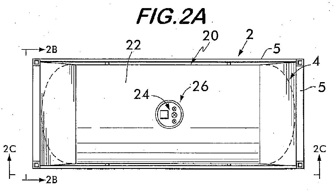
- the invention 20 comprises a container 22 that occupies a large portion of the fixed volume of a support structure 2 (discussed earlier) and exemplary equipment 24 (e.g., process or service equipment and appurtenances, also discussed earlier) that is positioned within a recess 26 within the outer surface of the container 22.
- equipment 24 e.g., process or service equipment and appurtenances, also discussed earlier
- the equipment 24 does not project beyond the periphery 27 of the outer surface of the container 22.
- the size of the container 22 fills a greater portion of the support structure 2 volume and greatly minimizes any unused volume 28 ( Fig. 3C ) within the support structure 2.
- An additional benefit of locating any process/service equipment and/or appurtenances inside the recess 26 is a significant decrease in the risk of damage and hence increased safety.
- Fig. 4 provides a top plan view of the recess 26 of the container 22.
- the equipment 24 in the recess 26 comprises at least one valve for providing communication to the interior of the container 22.
- the product carried within the container 22 may comprise a solid, liquid and/or gaseous phase product.
- 5-6 comprise a cross-sectional view of an upper portion of the container 22 and recess 26; these views depict a solid or liquid phase product forming the contents 23 of the container 22 and having an upper level indicated by the reference number 60A, it being understood that a gaseous phase product would occupy the entire volume of the container 22 and thus would not exhibit an "upper level 60A.”
- Product is introduced to, and removed from, the container 22 using a product valve 32 and corresponding product tube 38, although, as will be discussed later, head space valves can also be used, with or without corresponding product tube.
- the recess 26 contains a first valve 30A, a second valve 30B and the product valve 32.
- the valves 30A-30B (also referred to as “head space valves") are coupled to respective legs 34A and 34B (see Fig. 6 ) of secondary transport lines 36A and 36B, as will be discussed in detail later;
- the product valve 32 is coupled to the product tube 38 which includes an open end (not shown) that reaches to the bottom of, or closely-adjacent the bottom of, the container 22.
- the number of valves, as well as the number of secondary transport lines are by way of example only.
- the bottom or base of the recess 26 comprises a manway 40 that is releasably secured to the container 22 via releasable securement means 42 (e.g., nuts and bolts).
- the manway 40 rests on an annular shoulder 44 of an opening 46 ( Figs. 5 and 6 ) in the container 22.
- the manway 40 can be removed, thereby providing direct access by authorized personnel to the inside of the container 22 for inspection, maintenance, and other procedures requiring direct access; lugs 41 may be provided for grasping the manway 40.
- the legs 34A and 34B of the secondary transport lines 36A and 36B, as well as the tube 38, are fixedly or releasably secured (e.g., welded, brazed, etc.) to the manway 40; thus, when the manway 40 is removed, the valves 30A-30B and 32, along with the secondary transport lines 36A and 36B and tube 38, are removed with the manway 40.
- This feature of having the secondary transport lines 36A/36B and the tube 38 removed along with the manway 40 is desirable because it provides for the opening 46 to be unobstructed when authorized pesonnel must conduct inspection, maintenance, and other procedures requiring direct access to the container 22 interior.
- a circumferential brim 48 protrudes downward into the container 22, the importance of which will be discussed later.
- a housing 50 sized and shaped to meet product flow requirements that encloses the respective open-ended legs 52A/52B of the secondary transport lines 36A and 36B, as well as one open-ended leg 53 of a primary transport line 54 when the manway 40 is installed; when the manway 40 is removed, the leg 53 of the primary transport line 54 is exposed to the environment.
- the other open-ended leg 56 of the primary transport line 54 is secured to the inside of the container 22; for example, using an arm 58 and fitting 59.
- the housing 50 also does not protrude beyond the periphery 27 of the container 22.
- the head space valves 30A-30B, primary/secondary transport lines 54 and 36A/36B and product valve/tube 32 and 38 can be used in combination to effect the removal of the product when the container 22 is at the delivery point.
- Fig. 5 indicates three exemplary liquid levels, 60A, 608 and 60C that are referred to in the following functional example, given the existence of liquid and gaseous (vapor) phase product in the container 22.
- the liquid level is at height 60A, as mentioned earlier, there is complete vapor withdraw through one or both of the secondary transport legs 36A/36B, i.e., vapor is drawn directly from the first head space 62 of the container 22, through the primary transport line 54, into the housing 50 and then through the secondary transport lines 36A and/or 36B and through the respective valves 30A/30B.
- the functionality of the circumferential brim 48 is realized in preventing liquid entrainment.
- Entrainment as used in this example is defined as liquid phase product or product contaminants gaining access into the primary or secondary transport lines; entrainment covers any type of liquid phase product entry into the transport lines, including droplets of liquid phase product.
- the circumferential brim 48 creates a liquid head that is significantly large as compared to that in the secondary transport lines 36A and 36B (approximately zero) and prevents the entrainment of liquid directly through the housing 50.
- the liquid height drops below level 60C, vapor is directly drawn through the housing 50 into the secondary transport lines 36A and 36B where liquid entrainment through the secondary transport lines 36A/36B is no longer a concern.
- the length 64 of the brim 48 represents a threshold distance at which the liquid level of the entire container 22 no longer presents an entrainment concern to the open ends of legs 53 and 52A/52B of the respective transport lines.
- the invention 20 as described in the previous paragraphs can also deliver liquid phase product through the application of positive pressure to head space valves 30A and/or 30B, e.g., by coupling a pump, not shown, to one or both of the valves 30A/30B.
- a pump not shown
- liquid product is forced out through the product tube 38.
- pulling a vacuum on product valve 32 serves to recover liquid phase product, e.g., by coupling a vacuum source, not shown, to the product valve 32 to force liquid phase product up through the tube 38 and out of the valve 32.
- the invention 20 can also deliver solid phase product (e.g., particulate or granular), such as shown in Fig. 9A , by applying positive pressure through the product valve 32/product tube 38 with a gas that agitates such a solid. Then, by pulling a vacuum through, or creating a pressure differential across, head space valves 30A and/or 30B, the solid phase product passes through the primary transport line 54 and through one or both of the secondary transport lines 36A/36B, as discussed previously with respect to vapor removal using those lines. Furthermore, if the solid is particulate, granular or gel-like it could also be withdrawn through the product tube 38 and product valve 32 utilizing a vacuum.
- solid phase product e.g., particulate or granular
- the invention 20 can also deliver gaseous phase product by simply opening/closing the head space valves 30A/30B, with the passage of the gaseous phase product through the transport lines 54 and 36A/36B in accordance with the vapor removal discussed previously. Additionally, opening/closing of the product valve 32 can also be used to remove the gaseous phase product.
- Figs. 3A-3C show the container 22 of the present invention 20 used in a closed support structure 2'.
- a plurality of container skids 10A-10C may be used to stabilize the container 22 therein.
- the construction of the container 22 and the equipment 24 of the present invention 20 is similar to that described earlier in Figs. 2A-2C and 4-6 and is not repeated here.
- the closed support structure 2' of Figs. 3A-3C can also represent any generally confined area, i.e. an environment into which the container 22 can be positioned and wherein the equipment 24 does not protrude out of this generally confined area 2'.
- the container 22 maximizes the quantity of product contained within this volume while avoiding any clearance problems by the use of the recessed equipment 24.
- Figs. 7A-10C depict other variations of the container 22 wherein product (e.g. solid, liquid or gaseous phase) withdraw can be achieved using the primary transport line 54 and the secondary transport line 36A or 36B when the product level is above the head space valves 30A or 30B, with or without the use of the recess 26.
- product e.g. solid, liquid or gaseous phase
- the number of head space valves, as well as the number of secondary transport lines are by way of example only.
- the head space valves 30A/30B are positioned on the outside surface of the container 122 (which does not include any recess 26) at a location different from a conventional manway 140; thus, the head space valves 30A/30B, the housing 50, as well as the product valve 32, jut out of the periphery 127 of the container 122 but not out of the support structure 2.
- the important aspect of container 122 is that the bottom 31 of the head space valve 30A or 30B is beneath the filled level 60A of the product 23.
- the head space valve 30A or 30B can be located at any location around the container 122. This can also be seen by Figs.
- FIG. 10A-10C where the head space valves 30A and 30B are located at the ends of the container 122 (see Fig. 10A ).
- the housing 50 itself can be located remotely from the head space valves 30A/30B and alternative locations are shown by the square symbols 150 and 250 in Figs. 7A and 10A .
- the bottom 33 of the product valve 32 can also be located beneath the filled level 60A of the product 23. Because of the location of the product valve 32, the tube 38 is bent, as shown most clearly in Fig. 7B .
- the brim 48 is incorporated into the elongated housing as indicated by reference number 148 ( Fig. 9 ).
- this elongated housing 148 operates similarly to the brim 48 in that it represents a threshold distance at which the liquid level of the entire container 122 no longer presents an entrainment concern to the open ends 53 and 52A/52B of the respective transport lines.
- the container 22 is a special case of container 122, i.e., use of the recess 26, by definition, places the bottom 31 of the head space valves 30A/30B below the filled level 60A of the product 23 (as can be seen most clearly in Fig. 6 ).
- positioning the bottom of the head space valves 30A/30B does not require the use of the recess 26 and those valves 30A/30B can be located in an infinite number of positions around the container 122 whereby the bottom 31 of the valves 30A/30B are located beneath the filled level 60A.
- Materials chosen for construction of the containers 22/122 are, for example, standard pressure vessel construction materials, low carbon steels and readily available stainless steels that are inherently inert to the product being used and are suitable for expected environmental and process conditions. In addition, these materials are readily available, formable, weldable, cost effective and proven. Additionally, aluminum, plastics or composite materials could be used to construct such a vessel. In some instances, it is desirable to condition, coat, or line the interior container surface as required for product purity.
- the usefulness of the present invention 20 is that it provides for a means for the delivery of product from a bulk supply portable or stationary container that maximizes the quantity of transportable product and incorporates and protects a removable manway and equipment (both process equipment and appurtenances).
- This invention 20 may be used for standard, high purity and/or ultra high purity product that proves useful for requirements spanning various grades of solids, liquids and/or gaseous phase products.
- the equipment 24 and manway 40 are located within the recess 26, should the container 22 ever become unstable (e.g. during container transport, loading or unloading, etc.) and sustain an impact, the equipment 24 and manway 40 are protected from rolling or shearing damage, thereby adding safety to the design.
Abstract
a) a product (23) therein;
b) an outer surface having a periphery (27);
c) equipment (24), coupled to the outer surface, that provides communication to the product in said container (22);
d) said outer surface further comprising a recess (26) for locating said equipment (24) therein, said recess (26) preventing said equipment (24) from protruding beyond said periphery (27) of said outer surface;
e) and a manway (40) that is releasably secured to the container (22) via releasable securement means (42) such that the manway (40) can be removed, thereby providing direct access to the inside of the container (22);
f) said equipment (24) being fixedly or releasably secured to the manway (40), thus, when the manway (40) is removed, the equipment (24) is removed with the manway (40) thereby providing for an opening (46) of the container (22) to be unobstructed.

Description
- This invention is directed toward the delivery of pure, high purity (HP) and/or ultra high purity (UHP) product (solid, liquid, and or gaseous phase substance) from an internationally transportable or stationary bulk container to an end user.
- Currently there is a need for a system that would allow for the maximization of deliverable product quantity as harbored by a container whose construction is governed by transportation local requirements. The system and container must be suitable for international transportation, meeting the requirements of the International Organization for Standardization (ISO) and/or the authority having jurisdiction in the transportation local. Additionally, stationary and/or portable domestic containers and delivery systems must meet the requirements of the U.S. Department of Transportation (DOT) regulations (e.g., 49 C.F.R. 7173.315 and 49 C.F.R. 7178.245). The pertinent requirements based on these standards require that the container design and fabrication include a support structure (e.g., a frame, etc.) that provides a secure base for transport, that process or service equipment must be arranged so that the equipment is protected from damage and that provisions for man access to the internal volume of the container must be provided.
- The use of portable bulk product containers or shells positioned in support structures for stationary support or for transportation by truck, railcar and/or ship is well-known. As shown by way of example in
Figs. 1A-1C , aprior art container 1 is positioned inside asupport structure 2 of predetermined dimensions. In most cases, the container is fixedly-secured within thesupport structure 2, although there are situations where the container may be releasably-secured within thesupport structure 2. In particular, thecontainer 1 is fixedly secured (e.g., welded) to thesupport structure 2 viaend skirts 3 and 4. As can be seen most clearly inFig. 1B , each end skirt (only one of which, 3, is shown inFig. 1B , it being understood that end skirt 4 is similarly constructed) may comprise foursurfaces 3A-3D having edges that are fixedly secured (e.g., welded) tostruts 5 at the ends of thesupport structure 2. These end skirts are by way of example only and it should be understood that there are many other ways known in the art of securing thecontainer 1 within thesupport structure 2. - Furthermore, although not shown, process or service equipment (e.g., valves, pressure regulators, filters, etc.) and corresponding peripherals, referred to as "appurtenances" (e.g., covers, manways, safety chains, pressure gauges, etc.) are located on the outside surface of the
container 1 and protrude or jutt out from the periphery of thecontainer 1; hereinafter, the combination of process (or service) equipment and appurtenances are referred to as "equipment". For example, as shown inFigs. 1A-1C , aboss 6 represents an exemplary location of the equipment on theoutside surface 7 of thecontainer 1 and illustrates how such equipment generally protrudes from theperiphery 8 of acontainer 1. - Exemplary dimensions of a
support structure 2 containing acontainer 1 may comprise 20ft x 8ft x 8ft/6in. (e.g., ISO standard). The important aspect is that thesupport structure 2 establishes a fixed volume into which thecontainer 1, and all of its associated equipment, must be positioned. Therefore, the size of thecontainer 1 must be reduced to allow for inclusion of the equipment; this in turn reduces the quantity of product that can be carried by thecontainer 1. As a result, there is wastedvolume 9 in thesupport structure 2 but yet contained within thesupport structure 2 volume. - The following U.S. patents are exemplary patents related to the delivery of gaseous or liquid phase product from a container:
U.S. Patent Nos. 5,673,562 (Friedt );6,032,483 (Paganessi, et al. );6,089,027 (Wang, et al. );6,101,816 (Wang, et al. ); and6,122,931 (Paganessi, et al. ). -
U.S. Patent No. 6,032,483 (Jurcik, et al. ) discloses a system that is an on-site non-transportable system which utilizes one or a series of like or different distillation, absorption or adsorption columns and which processes a chemical where a heavy liquid is separated from the lighter vapor which is then delivered to the point of use. This non-transportable system uses pumps, heaters, columns, etc. to obtain and deliver the desired product. -
U.S. Patent No. 6,122,931 (Jurcik, et al. ) discloses a system for vapor delivery which includes a separation column or columns that accepts liquid delivered from a storage vessel containing a chemical stored under its own vapor pressure and separates out the vapor phase from liquid phase in a process utilizing the phase weight variance. The final vapor phase is provided to the point of delivery. This system utilizes external or internal columns to provide vapor and is also not transportable. -
U. S. Patent No. 6,089,027 (Tom, et al. ) discloses a fluid storage and dispensing system. The vessel used in that system has a volume of no greater than approximately 50 liters in its maximum aspect application and delivers fluid utilizing a fluid dispensing system but does not disclose the delivery of gaseous or solid phases. -
U.S. Patent No. 6,101,816 (Tom, et al. ) discloses a fluid dispensing system that utilizes a pressure regulator and a pulse separator or membrane for the separation of gas vapor and liquid product. This invention delivers only vapor phase product and utilizes external controls for the regulation of product conditions. -
U.S. Patent No. 5,071,166 (Marino ) discloses a transportable liquid holding tank that includes an inner tank and an outwardly-spaced rigid enclosure whereby a compartment is formed between these two items that supports an access assembly. -
EP 0 969 242 A2 andEP 0 969 243 A2 disclose torroidal containers that utilize head pieces for multiple valve groups. - The following patents give examples of containers that utilize inner and outer containers and/or are stored underground and utilize mechanisms to minimize leaks from these containers:
U.S. Patent Nos. 4,685,327 (Sharp );4,958,957 (Berg et al. );2,609,964 (Cadwell et al. ); and5,016,689 (McGarvey ); andEP 0 624 752 B1 (Poillucci ). - After an examination of the previously-cited prior art, it is apparent that there remains a need for a container that maximizes the amount of product-containing volume and that can be used with a support structure while complying with U.S. DOT regulations, as well as international transportation regulations. Additionally, there remains a need for such a container to be equipped with a system that facilitates the delivery of product to an end user at various levels of product entropy.
- A container whose interior comprises a first head space located above a product (e.g., a solid, liquid and/or gaseous phase product) contained therein, wherein the product comprises a filled level and wherein the container comprises a head space valve having a bottom that is located below the filled level.
- A container that is secured entirely within a support structure (e.g., a frame in accordance with U.S. Department of Transportation regulations and/or international transportation regulations such as the International Organization for Standardization) having a fixed volume. The container comprises: a product therein (e.g., a solid, liquid and/or gaseous phase product); an outer surface having a periphery; equipment (e.g., process/service equipment including valves, pressure regulators, filters, etc., and appurtenances including covers, manways, safety chains, pressure gauges, etc.), coupled to the outer surface, that provides communication to the product in the container; wherein the outer surface further comprises a recess for locating the equipment therein, and wherein the recess prevents the equipment from protruding beyond the periphery of the outer surface.
- A method for maximizing the amount of product (e.g., a solid, liquid and/or gaseous phase product) in a container whose interior comprises a first head space located above a product contained therein, wherein the product comprises a filled level and wherein the method comprises the steps of: placing a first valve in communication with the first head space; and locating a bottom of the first valve below the filled level.
- A method for maximizing the amount of product (e.g., a solid, liquid and/or gaseous phase product) in a container that is secured entirely within a support structure (e.g., a frame in accordance with U.S. Department of Transportation regulations and/or international transportation regulations such as the International Organization for Standardization) of a fixed volume. The method comprises the steps of: providing a container whose outer surface defines a periphery and wherein the container comprises a product therein; providing a recess in the outer surface; and positioning equipment (e.g., process/service equipment including valves, pressure regulators, filters, etc., and appurtenances including covers, manways, safety chains, pressure gauges, etc.) within the recess such that the recess prevents the equipment from protruding beyond the periphery of the outer surface and wherein the equipment provides communication to the product in the container.
- In the following, specific aspects of the container and method will be outlined. The reference signs and expressions set in parentheses are referring to an example embodiments explained further below with reference to figures. The reference signs and expressions are, however, only illustrative and do not limit the aspect to any specific component or feature of the example embodiments. The aspects can be formulated as claims in which the reference signs and expressions set in parentheses are omitted or replaced by appropriate others.
-
Aspect 1# A container comprising: - a) a product (23) therein;
- b) an outer surface having a periphery (27);
- c) equipment (24), coupled to the outer surface, that provides communication to the product in said container (22);
- d) said outer surface further comprising a recess (26) for locating said equipment (24) therein, said recess (26) preventing said equipment (24) from protruding beyond said periphery (27) of said outer surface;
- e) and a manway (40) that is releasably secured to the container (22) via releasable securement means (42) such that the manway (40) can be removed, thereby providing direct access to the inside of the container (22);
- f) said equipment (24) being fixedly or releasably secured to the manway (40), thus, when the manway (40) is removed, the equipment (24) is removed with the manway (40) thereby providing for an opening (46) of the container (22) to be unobstructed.
-
Aspect 2# A container that maximizes the quantity of transportable product and incorparates and protects a removable manway (40) and equipment (24) which is fixedly or releasably secured to the manway (40), thus, when the manway (40) is removed, the equipment (24) is removed with the manway (40) thereby providing for an opening (46) of the container (22) to be unobstructed. -
Aspect 3# The container of any one of the preceding aspects, wherein the equipment (24) comprises at least one valve (30A, 30B, 32) for providing communication to the interior of the container (22). - Aspect 4# A container whose interior comprises a first head space (62) located above a product contained therein, wherein the product comprises a filled level, said container (22) comprising a head space valve (30A, 30B) and a removable manway (40), wherein the head space valve (30A, 30B) is fixedly or releasably secured to the manway (40), thus, when the manway (40) is removed, the head space valve (30A, 30B) is removed with the manway (40) thereby providing for an opening (46) of the container (22) to be unobstructed.
-
Aspect 5# The container of the preceding aspect, wherein said head space valve (30A, 30B) has a bottom that is located below said filled level. -
Aspect 6# A container according to any one of theaspects 2 to 5, wherein the manway (40) and the equipment (24) or valve (30A, 30B, 32) are located within a recess (26) provided in an outer surface of the container (22) the outer surface having a periphery (27), said recess (26) preventing said equipment (24) or valve (30A, 30B, 32) from protruding beyond said periphery (27). -
Aspect 7# The container of any one of the preceding aspects, wherein the manway (40) rests on an annular shoulder (44) of the opening (46) in the container (22). -
Aspect 8# The container of any one of the preceding aspects, wherein lugs (41) are provided for grasping the manway (40). -
Aspect 9# The container of any one of the preceding aspects, wherein the manway (40) forms a base of the recess (26). -
Aspect 10# The container of any one of the preceding aspects, wherein the recess (26) contains a head space valve (30A, 30B) coupled to a leg (34A, 34B) of a secondary transport line (36A, 36B), and/or a product valve (32) coupled to a product tube (38) which includes an open end that reaches to or closely-adjacent a bottom of the container (22), and wherein said leg (34A, 34B) and/or product tube (38) are/is fixedly or releasably secured to said manway (40). - Aspect 11# A container comprising:
- a) a product therein;
- b) an outer surface having a periphery (27);
- c) equipment (24), coupled to said outer surface, that provides communication to the product in said container (22);
- d) said outer surface further comprising a recess (26) for locating said equipment (24) therein, said recess (26) preventing said equipment (24) from protruding beyond said periphery (27) of said outer surface; and
- e) said recess (26) further comprising a base;
- f) wherein said base comprises a manway (40) that is releasably secured to an edge of an opening in said container (22).
- Aspect 12# The container of any one of the preceding aspects, wherein said container (22) is secured entirely within a support structure (2) having a fixed volume.
- Aspect 13# The container of any one of the preceding aspects, wherein said container (22) comprises a first head space (62) located above the product and wherein said equipment (24) comprises a head space valve (30A, 30B).
- Aspect 14# The container of any one of the preceding aspects, wherein said recess (26) further comprises:
- a housing (50) coupled to said container (22) or said base of aspect 11 and having an interior that is exposed to the product in said container (22) and that contains a second head space (62') above the product;
- a primary transport line (54) having a first open end positioned in said first head space (62) and a second open end positioned in said second head space (62'); and
- a secondary transport line (36A, 36B) having a third end coupled to said head space valve (30A, 30B) and a fourth open end disposed in said second head space (62').
- Aspect 15# The container of aspect 14, wherein said housing (50) and said secondary transport line (36A, 36B) are coupled to said manway (40) such that when said manway (40) is removed from said edge, said housing (50) and said secondary transport line (36A, 36B) are also removed therewith.
- Aspect 16# The container of any one of the preceding aspects, wherein said equipment (24) comprises a product valve (32) and wherein said container (22) comprises a product tube (38) in communication with said product valve (32), said product tube (38) being coupled to said manway (40) and having an open end that is disposed in the product when said manway (40) is secured to the container (22), said product tube (38) being removed with said manway (40) when said manway (40) is removed from the container (22).
- Aspect 17# The container of any one of the preceding aspects, wherein the container (22) is a portable or stationary bulk product container for the delivery of pure, high purity (HP and/or ultra high purity (UHP) product to a user, and wherein the product is a compressed liquefied gas, preferably ammonia.
- Aspect 18# A method for maximizing the amount of product in a container (22) that is secured entirely within a support structure (2) of a fixed volume, said method comprising the steps of:
- a) providing a container (22) whose outer surface defines a periphery (27);
- b) wherein said container (22) comprises a product therein;
- c) providing a recess (26) in said outer surface; and
- d) positioning equipment (24) within said recess (26) such that said recess (26) prevents said equipment (24) from protruding beyond said periphery (27) of said outer surface, said equipment providing communication to the product in said container (22);
- e) wherein said step of providing a recess (26) comprises providing a base for said recess (26);
- f) and wherein said step of providing a base comprises providing a manway (40) that is releasably secured to an edge of an opening (46) in said container (22).
- Aspect 19# The method of the preceding aspect wherein said step of positioning equipment (24) within said recess (26) comprises providing a first valve (30A, 30B) therein, said first valve (30A, 30B) being in communication with an upper portion of a first interior (62) of said container (22).
-
Aspect 20# The method of any one of the two preceding aspects, wherein said step of providing a recess (26) comprises: - providing a housing (50) coupled to said base and wherein said housing (50) has a second interior (62') that is exposed to the product in said container (22);
- positioning a first open end of a primary transport line (54) in said upper portion of said first interior (62) of said container (22) and positioning a second open end of said primary transport line (54) in said second interior (62') of said housing (50); and
- coupling a third end of a secondary transport line (36A, 36B) to said first valve (30A, 30B) and positioning a fourth open end of said secondary transport line (36A, 36B) in said second interior (62') of said housing (50).
- Aspect 21# The method of the preceding aspect, wherein said step of providing a third end of a secondary transport line (36A, 36B) comprises coupling said secondary transport line (36A, 36B) to said manway (40) such that when said manway (40) is removed from said edge, said housing (50) and said secondary transport line (36A, 36B) are also removed therewith.
-
Aspect 22# The method of any one of aspects 18 to 21 further comprising the steps of: - providing a product valve (32) in said recess (26);
- coupling one end of the product tube (38) to said product valve (32); and
- coupling said product tube (38) to said manway (40) such that an open end of the product tube (38) is positioned in said container (22) closely-adjacent a bottom portion of that container (22) when said manway (40) is secured to said edge and wherein said product tube (38) is removable with said manway (40) when said manway (40) is removed from said edge.
-
Aspect 23# The method of any one of aspect s18 to 22 further comprising the step of coupling a brim (48) arround said opening (46), said brim (48) projecting into a first interior (62) of said container (22). -
Aspect 24# The method of any one of aspects 18 to 23 in combination with aspect 19, wherein said product is a liquified compressed gas, preferably ammonia, comprising a liquid phase and a vapor phase, said method further comprising the step of removing said vapor phase by passing said vapor phase through said first valve (30A, 30B), preferably through said primary transport line (54) and said secondary transport line (36A, 36B) ofaspect 20 and out through said first valve (30A, 30B). - Aspect 25# A container (22) whose interior comprises a first head space (62) located above a product contained therein and wherein the product comprises a filled level, said container comprising a head space valve (30A, 30B) having a bottom that is preferably located below said filled level.
-
Aspect 26# The container of any of the preceding aspects further comprising: - a housing (50) coupled to said container (22) and having a housing interior that is exposed to the product in said container (22), said housing (50) comprising a second head space (62') above the product;
- a primary transport line (54) having a first open end positioned in said first head space (62) and a second open end positioned in said second head space (62'); and
- a secondary transport line (36A, 36B) having a third end coupled to said head space valve (30A, 30B) and a fourth open end disposed in said second head space (62').
-
Aspect 27# The container ofaspect 26 wherein said product comprises a liquid phase and a vapor phase, said vapor phase occupying said first and second head spaces (62, 62'), said vapor phase being removable from said container (22) through said primary and secondary transport lines (54, 36A, 36B) and said head space valve (30A, 30B). -
Aspect 28# The container ofaspect 27 wherein said housing (50) comprises a brim (48) that projects into said container (22). - Aspect 29# The container of
aspect 26 wherein said product is a solid phase product, said solid phase product being removable from said container (22) through said primary and secondary transport lines (54, 36A, 36B) and said head space valve (30A, 30B). - Aspect 30# The container of
aspect 26 wherein said product is a gaseous phase product, said gaseous phase product being removable from said container (22) through said primary and secondary transport lines (54, 36A, 36B) and said head space valve (30A, 30B). -
Aspect 31# The container ofaspect 26 being secured entirely within a support structure (2) having a fixed volume. -
Aspect 32# The container ofaspect 31 further comprising an outer surface having a periphery (27), said outer surface comprising a recess (26) for locating said head space valve (30A, 30B) and said housing (50) therein, said recess (26) preventing said head space valve (30A, 30B) and said housing (50) from protruding beyond said periphery (27) of said outer surface. -
Aspect 33# A container that is secured entirely within a support structure (2) having a fixed volume, said container (22) comprising: - a product therein;
- an outer surface having a periphery (27);
- equipment (24) coupled to said outer surface, that provides communication to the product in said container (22); and
- said outer surface further comprising a recess (26) for locating said equipment (24) therein, said recess (26) preventing said equipment (24) from protruding beyond said periphery (27) of said outer surface.
- Aspect 34# The container of the preceding aspect further comprising a first head space (62) located above the product and wherein said equipment (24) comprises a head space valve (30A, 30B).
- Aspect 35# The container of the preceding aspect wherein said recess (26) further comprises:
- a base;
- a housing (50) coupled to said base and having an interior that is exposed to the product in said container (22) and that contains a second head space (62') above the product;
- a primary transport line (54) having a first open end positioned in said first head space (62) and a second open end positioned in said second head space (62'); and
- a secondary transport fine (36A, 36B) having a third end coupled to said head space valve (30A, 30B) and a fourth open end disposed in said second head space (62').
- Aspect 36# The container of the preceding aspect wherein said base comprises a manway (40) that is releasably secured to an edge of an opening in said container (22), said housing (50) and said secondary transport line (36A, 36B) being coupled to said manway (40) such that when said manway (40) is removed from said edge, said housing (50) and said secondary transport fine (36A, 36B) are also removed therewith.
- Aspect 37# The container of the preceding aspect wherein said equipment (24) further comprises a product valve (32) and wherein said container (22) further comprises a product tube (38) in communication with said product valve (32), said product tube (38) being coupled to said manway (40) and having an open end that is disposed in the product when said manway (40) is secured to said edge, said product tube (38) being removed with said manway (40) when said manway (40) is removed from said edge.
-
Aspect 38# The container of the preceding aspect wherein said product comprises a liquid phase and a vapor phase, said vapor phase occupying said first and second head spaces, said vapor phase being removable from said container through said primary and secondary transport lines and said head space valve. - Aspect 39# The container of the preceding aspect wherein said opening comprises a brim that projects into said container.
-
Aspect 40# The container of aspect 35 wherein said product is a solid phase product, said solid phase product being removable from said container through said primary and secondary transport lines and said head space valve. -
Aspect 41# The container of aspect 35 wherein said product is a gaseous phase product, said gaseous phase product being removable from said container through said primary and secondary transport lines and said head space valve. -
Aspect 42# A method for maximizing the amount of product in a container (22) whose interior comprises a first head space (62) located above a product contained therein and wherein the product comprises a filled level, said method comprises the steps of: - placing a first valve (30A) in communication with said first head space (62); and
- locating a bottom of said first valve (30A) below said filled level.
- Aspect 43# The method of the preceding aspect further comprising:
- providing a housing (50) coupled to said container (22) and wherein said housing (50) has a second interior that is exposed to the product in said container (22);
- providing a first open end of a primary transport line (54) in said upper portion of said first interior (62) of said container (22) and positioning a second open end of said primary transport line (54) in said second interior of said housing (50); and
- coupling a third end of a secondary transport line (36A, 36B) to said first valve (30A) and positioning a fourth open end of said secondary transport line (36A, 36B) in said second interior (62') of said housing (50).
-
Aspect 44# The method of any of the two preceding aspects further comprising the step of providing a brim (48) under said housing, said brim (48) projecting into said first interior (62) of said container (22). - Aspect 45# The method of the three preceding aspects wherein said product comprises a liquid phase and a vapor phase, said method further comprising the step of removing said vapor phase by passing said vapor phase through said primary transport line (54), through said secondary transport line (36A, 36B) and out through said first valve (30A).
-
Aspect 46# The method of any of the four preceding aspects wherein said product is a solid phase product, said method further comprising the steps of: - providing a second valve (30B) that is in fluid communication with said container interior;
- coupling one end of a product tube (38) to said second valve (30B);
- applying a positive pressure of a gas to said second valve (30B) to agitate said solid phase product; and
- applying a vacuum to said first valve (30A) to pass said solid phase through said primary transport line (54), through said secondary transport line (36A, 36B) and out through said first valve (30A) to remove said solid phase product from said container (22).
- Aspect 47# The method of any of the five preceding aspects wherein said product is a solid phase product, said method further comprising the steps of:
- providing a second valve (30B) that is in fluid communication with said container interior;
- coupling one end of a product tube (38) to said second valve (36B);
- applying a positive pressure of a gas to said second valve (36B) to agitate said solid phase product; and
- applying a pressure differential to said first valve (30A) to pass said solid phase through said primary transport line (54), through said secondary transport line (36A, 36B) and out through said first valve (30A) to remove said solid phase product from said container (22).
-
Aspect 48# The method of any of the six preceding aspects wherein said product is a gaseous phase product, said method comprising the step of opening said first valve (30A) to pass said gaseous phase through said primary transport line (54), through said secondary transport line (36A, 36B) and out through said first valve (30A) to remove said gaseous phase product from said container (22). - Aspect 49# The method of any of the seven preceding aspects wherein said container (22) comprises an outer surface that defines a periphery (27) and wherein said step of locating a bottom of said first valve (30A) below said filled level comprises:
- providing a recess (26) in said outer surface; and
- positioning said first valve (30A) in said recess (26) such that said recess (26) prevents said first valve (30A) from protruding beyond the periphery (27) of said outer surface.
-
Aspect 50# A method for maximizing the amount of product in a container (22) that is secured entirely within a support structure (2) of a fixed volume, said method comprising the steps of: - providing a container (22) whose outer surface defines a periphery (27); and
- wherein said container (22) comprises a product therein;
- providing a recess (26) in said outer surface; and
- positioning equipment (24) within said recess (26) such that said recess (26) prevents said equipment (24) from protruding beyond said periphery (27) of said outer surface, said equipment providing communication to the product in said container (22).
- Aspect 51# The method of the preceding aspect wherein said step of positioning equipment (24) within said recess (26) comprises providing a first valve (30A) therein, said first valve (30A) being in communication with an upper portion of a first interior (62) of said container (22).
- Aspect 52# The method of any of the two preceding aspects wherein said step of providing a recess (26) comprises:
- providing a base for said recess (26);
- optionally providing a housing (50) coupled to said base and wherein said housing (50) has a second interior (62') that is exposed to the product in said container (22);
- optionally positioning a first open end of a primary transport line (54) in said upper portion of said first interior (62) of said container (22) and positioning a second open end of said primary transport line (54) in said second interior (62') of said housing (50); and
- optionally coupling a third end of a secondary transport line (36A, 36B) to said first valve (30A) and positioning a fourth open end of said secondary transport line (36A, 36B) in said second interior (62') of said housing (50).
-
Aspect 53# The method of the preceding aspect wherein said step of providing a base comprises providing a manway (40) that is releasably secured to an edge of an opening in said container (22). -
Aspect 54# The method of the preceding aspect wherein said step of providing a third end of a secondary transport line (36A, 36B) comprises coupling said secondary transport line (36A, 36B) to said manway (40) such that when said manway (40) is removed from said edge, said housing (50) and said secondary transport line (36A, 36B) are also removed therewith. - Aspect 55# The method of any one of the two preceding aspects further comprising the steps of:
- providing a second (30B) valve in said recess (26);
- coupling one end of a product tube (38) to said second valve (30B); and
- coupling said product tube (38) to said manway (40) such that an open end of said product tube (38) is positioned in said container (22) closely-adjacent a bottom portion of said container (22) when said manway (40) is secured to said edge and wherein said product tube is removable with said manway when said manway is removed from said edge.
- Aspect56# The method of the preceding aspect further comprising the step of coupling a brim around said opening, said brim projecting into said first interior of said container.
- Aspect 57# The method of any one of the two preceding aspects wherein said product comprises a liquid phase and a vapour phase, said method further comprising the step of removing said vapour phase by passing said vapour phase through said primary transport line, through said secondary transport line and out through said first valve.
-
Aspect 58# The method of any of the three preceding aspects wherein said product is a solid phase product, said method further comprising the steps of: - applying a positive pressure of a gas to said second valve to agitate said solid phase product, and
- applying a vacuum to said first valve to pass said solid phase through said primary transport line, through said secondary transport line and out
- through said first valve to remove said solid phase product from said container.
-
Aspect 59# The method of any of the four preceding aspects wherein said product is a solid phase product, said method further comprising the steps of: - applying a positive pressure of a gas to said second valve to agitate said solid phase product; and
- applying a pressure differential to said first valve to pass said solid phase through said primary transport line, through said secondary transport line and out through said first valve to remove said solid phase product from said container.
- Aspect 60# The method of any of the five preceding aspects wherein said product is a gaseous phase product, said method comprising the steps of opening said first valve to pass said gaseous phase through said primary transport line, through said secondary transport line and out through said first valve to remove said gaseous phase product from said container.
- The invention will be described by way of example with reference to the accompanying drawings, in which:
-
Fig. 1A is a top view of an exemplary prior art container secured within a support structure showing the use of end skirts with the prior art container ends shown in phantom; -
Fig. 1B is a partially broken-away end view of the prior art container and support structure taken alongline 1 B-1 B ofFig. 1A ; -
Fig. 1C a side view of the prior art container and support structure taken alongline 1C-1C ofFig. 1A ; -
Fig. 2A is a top view of the present invention container secured within a support structure showing the use of end skirts with the present invention container ends shown in phantom; -
Fig. 2B is an end view of the present invention container and support structure taken alongline 2B-2B ofFig. 2A showing the recess and equipment therein in phantom; -
Fig. 2C a side view of the present invention container and support structure taken alongline 2C-2C ofFig. 2A ; -
Fig. 3A is a top view of the present invention container secured within another support structure, or generally confined area, showing the use of container skids in phantom; -
Fig. 3B is an end view of the present invention container and support structure taken alongline 3B-3B ofFig. 3A showing the recess and example equipment therein in phantom; -
Fig. 3C a side view of the present invention container and support structure taken alongline 3C-3C ofFig. 3A ; -
Fig. 4 is top plan view of the internals of the recess in the container of the present invention; -
Fig. 5 is a side, cross-sectional view of the recess in the container taken along line 5-5 ofFig. 4 ; -
Fig. 6 is a back, cross-sectional view of the recess in the container taken along line 6-6 ofFig. 4 ; -
Fig. 7A is a top view of another embodiment of a container of the present invention secured within a support structure showing the use of end skirts with the container ends shown in phantom; -
Fig. 7B is an end view of the present invention container ofFig. 7A taken alongline 7B-7B ofFig. 7A ; -
Fig. 7C is a side view of the present invention container ofFig. 7A taken alongline 7C-7C ofFig. 7A ; -
Fig. 8 is an enlarged view of the valves and transport lines, shown in phantom, that are shown inFig. 7A ; -
Fig. 9 is a cross-sectional view of the enlarged area ofFig. 8 taken along line 9- 9 ofFig. 8 ; -
Fig. 9A is a similar cross-sectional view of the enlarged area ofFig. 8 taken along line 9-9 ofFig. 8 but showing a solid phase product (e.g., particulate or granular); -
Fig. 10A is a top view of a third embodiment of a container of the present invention secured within a support structure showing the use of end skirts with the container ends shown in phantom; -
Fig. 10B is an end view of the present invention container ofFig. 10A taken alongline 10B-10B ofFig. 10A ; and -
Fig. 10C is a side view of the present invention container ofFig. 10A taken alongline 10C-10C ofFig. 10A . - The
invention 20 maximizes the product volume of a portable or stationary container by having the capability of product recovery when the product level is above the delivery valve(s). Theinvention 20 provides for a portable or stationary bulk product container designed for vacuum and/or atmospheric and positive pressures, and having an integral product delivery system that supports a range of flow rates and is sized for the application. It should be understood that the term "product" used hereinafter includes solid, liquid and/or gaseous phase product. Exemplary solids may include but are not limited to the following: powder (e.g., graphite, etc.); particulate; slurry (e.g., mixture of two substances one liquid and one solid). Exemplary liquids may include but are not limited to the following: milk, water, ink, paint, any compressed liquefied gas (e.g., ammonia; butadiene, inhibited; carbon dioxide, refrigerated liquid; chlorine; ethane, refrigerated liquid; ethane-propane mixture, refrigerated liquid; hexafluoropropylene; hydrogen chloride, refrigerated liquid; liquefied petroleum gas; methyl chloride; methyl mercaptan; nitrous oxide, refrigerated liquid; sulfur dioxide; vinyl methyl ether; etc.). Exemplary gaseous phases may include but are not limited to the following: the vapor phase of the above listed liquid phase products (e.g., ammonia; chlorine, nitrogen etc.). - In particular, as shown in
Figs. 2A-2C , theinvention 20 comprises acontainer 22 that occupies a large portion of the fixed volume of a support structure 2 (discussed earlier) and exemplary equipment 24 (e.g., process or service equipment and appurtenances, also discussed earlier) that is positioned within arecess 26 within the outer surface of thecontainer 22. As can be seen fromFigs. 2A-2C , theequipment 24 does not project beyond theperiphery 27 of the outer surface of thecontainer 22. As a result, the size of thecontainer 22 fills a greater portion of thesupport structure 2 volume and greatly minimizes any unused volume 28 (Fig. 3C ) within thesupport structure 2. An additional benefit of locating any process/service equipment and/or appurtenances inside therecess 26 is a significant decrease in the risk of damage and hence increased safety. -
Fig. 4 provides a top plan view of therecess 26 of thecontainer 22. In general, theequipment 24 in therecess 26 comprises at least one valve for providing communication to the interior of thecontainer 22. In particular, as mentioned earlier, the product carried within thecontainer 22 may comprise a solid, liquid and/or gaseous phase product.Figs. 5-6 comprise a cross-sectional view of an upper portion of thecontainer 22 andrecess 26; these views depict a solid or liquid phase product forming thecontents 23 of thecontainer 22 and having an upper level indicated by thereference number 60A, it being understood that a gaseous phase product would occupy the entire volume of thecontainer 22 and thus would not exhibit an "upper level 60A." Product is introduced to, and removed from, thecontainer 22 using aproduct valve 32 andcorresponding product tube 38, although, as will be discussed later, head space valves can also be used, with or without corresponding product tube. - As shown by way of example only in
Fig. 4 , therecess 26 contains afirst valve 30A, asecond valve 30B and theproduct valve 32. Thevalves 30A-30B (also referred to as "head space valves") are coupled torespective legs Fig. 6 ) ofsecondary transport lines product valve 32 is coupled to theproduct tube 38 which includes an open end (not shown) that reaches to the bottom of, or closely-adjacent the bottom of, thecontainer 22. It should be understood that the number of valves, as well as the number of secondary transport lines, are by way of example only. - The bottom or base of the
recess 26 comprises amanway 40 that is releasably secured to thecontainer 22 via releasable securement means 42 (e.g., nuts and bolts). Themanway 40 rests on anannular shoulder 44 of an opening 46 (Figs. 5 and6 ) in thecontainer 22. Themanway 40 can be removed, thereby providing direct access by authorized personnel to the inside of thecontainer 22 for inspection, maintenance, and other procedures requiring direct access; lugs 41 may be provided for grasping themanway 40. Thelegs secondary transport lines tube 38, are fixedly or releasably secured (e.g., welded, brazed, etc.) to themanway 40; thus, when themanway 40 is removed, thevalves 30A-30B and 32, along with thesecondary transport lines tube 38, are removed with themanway 40. This feature of having thesecondary transport lines 36A/36B and thetube 38 removed along with themanway 40 is desirable because it provides for theopening 46 to be unobstructed when authorized pesonnel must conduct inspection, maintenance, and other procedures requiring direct access to thecontainer 22 interior. In addition, a circumferential brim 48 (Fig. 5 ) protrudes downward into thecontainer 22, the importance of which will be discussed later. - Also releasably or fixedly-secured to the
manway 40 is ahousing 50 sized and shaped to meet product flow requirements that encloses the respective open-endedlegs 52A/52B of thesecondary transport lines ended leg 53 of aprimary transport line 54 when themanway 40 is installed; when themanway 40 is removed, theleg 53 of theprimary transport line 54 is exposed to the environment. The other open-ended leg 56 of theprimary transport line 54 is secured to the inside of thecontainer 22; for example, using anarm 58 andfitting 59. As with theequipment 24, thehousing 50 also does not protrude beyond theperiphery 27 of thecontainer 22. - Depending on the type of product within the
container 22, thehead space valves 30A-30B, primary/secondary transport lines tube container 22 is at the delivery point. -
Fig. 5 indicates three exemplary liquid levels, 60A, 608 and 60C that are referred to in the following functional example, given the existence of liquid and gaseous (vapor) phase product in thecontainer 22. When the liquid level is atheight 60A, as mentioned earlier, there is complete vapor withdraw through one or both of thesecondary transport legs 36A/36B, i.e., vapor is drawn directly from thefirst head space 62 of thecontainer 22, through theprimary transport line 54, into thehousing 50 and then through thesecondary transport lines 36A and/or 36B and through therespective valves 30A/30B. As the liquid level drops to betweenlevels circumferential brim 48 is realized in preventing liquid entrainment. "Entrainment" as used in this example is defined as liquid phase product or product contaminants gaining access into the primary or secondary transport lines; entrainment covers any type of liquid phase product entry into the transport lines, including droplets of liquid phase product. In particular, thecircumferential brim 48 creates a liquid head that is significantly large as compared to that in thesecondary transport lines housing 50. When the liquid height drops belowlevel 60C, vapor is directly drawn through thehousing 50 into thesecondary transport lines secondary transport lines 36A/36B is no longer a concern. In other words, if thecircumferential brim 48 were not present, once the liquid reachedlevel 60B, the open ends of thelegs secondary transport lines liquid level 60B of theentire container 22. In contrast, with thecircumferential brim 48 in place, the open ends oflegs circumferential brim 48. Thus, thelength 64 of thebrim 48 represents a threshold distance at which the liquid level of theentire container 22 no longer presents an entrainment concern to the open ends oflegs - Other examples of the use of the
invention 20 for delivering liquid and solid phases of product are as follows: - The
invention 20 as described in the previous paragraphs can also deliver liquid phase product through the application of positive pressure to headspace valves 30A and/or 30B, e.g., by coupling a pump, not shown, to one or both of thevalves 30A/30B. As pressure builds in the top of thecontainer 22, liquid product is forced out through theproduct tube 38. Alternatively, pulling a vacuum onproduct valve 32 serves to recover liquid phase product, e.g., by coupling a vacuum source, not shown, to theproduct valve 32 to force liquid phase product up through thetube 38 and out of thevalve 32. - The
invention 20 can also deliver solid phase product (e.g., particulate or granular), such as shown inFig. 9A , by applying positive pressure through theproduct valve 32/product tube 38 with a gas that agitates such a solid. Then, by pulling a vacuum through, or creating a pressure differential across,head space valves 30A and/or 30B, the solid phase product passes through theprimary transport line 54 and through one or both of thesecondary transport lines 36A/36B, as discussed previously with respect to vapor removal using those lines. Furthermore, if the solid is particulate, granular or gel-like it could also be withdrawn through theproduct tube 38 andproduct valve 32 utilizing a vacuum. - The
invention 20 can also deliver gaseous phase product by simply opening/closing thehead space valves 30A/30B, with the passage of the gaseous phase product through thetransport lines product valve 32 can also be used to remove the gaseous phase product. -
Figs. 3A-3C show thecontainer 22 of thepresent invention 20 used in a closed support structure 2'. A plurality of container skids 10A-10C may be used to stabilize thecontainer 22 therein. The construction of thecontainer 22 and theequipment 24 of thepresent invention 20 is similar to that described earlier inFigs. 2A-2C and4-6 and is not repeated here. It should be appreciated that the closed support structure 2' ofFigs. 3A-3C can also represent any generally confined area, i.e. an environment into which thecontainer 22 can be positioned and wherein theequipment 24 does not protrude out of this generally confined area 2'. Thus, for example, with thecontainer 22 itself of thepresent invention 20 positioned in any space having a volume corresponding to the closed support structure 2', thecontainer 22 maximizes the quantity of product contained within this volume while avoiding any clearance problems by the use of the recessedequipment 24. -
Figs. 7A-10C depict other variations of thecontainer 22 wherein product (e.g. solid, liquid or gaseous phase) withdraw can be achieved using theprimary transport line 54 and thesecondary transport line head space valves recess 26. As with thecontainer 22, it should be understood that the number of head space valves, as well as the number of secondary transport lines, are by way of example only. - In particular,
Figs. 7A-10C , thehead space valves 30A/30B are positioned on the outside surface of the container 122 (which does not include any recess 26) at a location different from aconventional manway 140; thus, thehead space valves 30A/30B, thehousing 50, as well as theproduct valve 32, jut out of theperiphery 127 of thecontainer 122 but not out of thesupport structure 2. As shown most clearly inFig. 9 , the important aspect ofcontainer 122 is that the bottom 31 of thehead space valve level 60A of theproduct 23. In fact, thehead space valve container 122. This can also be seen byFigs. 10A-10C where thehead space valves Fig. 10A ). Thehousing 50 itself can be located remotely from thehead space valves 30A/30B and alternative locations are shown by thesquare symbols Figs. 7A and10A . Although not required, the bottom 33 of theproduct valve 32 can also be located beneath the filledlevel 60A of theproduct 23. Because of the location of theproduct valve 32, thetube 38 is bent, as shown most clearly inFig. 7B . - It should be noted that where the
housing 50 is remotely-located from themanway 140, as shown inFigs. 7A-10C , thebrim 48, as discussed in relation to thecontainer 22, is incorporated into the elongated housing as indicated by reference number 148 (Fig. 9 ). Thus, this elongated housing 148 operates similarly to thebrim 48 in that it represents a threshold distance at which the liquid level of theentire container 122 no longer presents an entrainment concern to the open ends 53 and 52A/52B of the respective transport lines. - In view of the
container 122, it can be seen that thecontainer 22 is a special case ofcontainer 122, i.e., use of therecess 26, by definition, places the bottom 31 of thehead space valves 30A/30B below the filledlevel 60A of the product 23 (as can be seen most clearly inFig. 6 ). However, positioning the bottom of thehead space valves 30A/30B does not require the use of therecess 26 and thosevalves 30A/30B can be located in an infinite number of positions around thecontainer 122 whereby the bottom 31 of thevalves 30A/30B are located beneath the filledlevel 60A. - Materials chosen for construction of the
containers 22/122 are, for example, standard pressure vessel construction materials, low carbon steels and readily available stainless steels that are inherently inert to the product being used and are suitable for expected environmental and process conditions. In addition, these materials are readily available, formable, weldable, cost effective and proven. Additionally, aluminum, plastics or composite materials could be used to construct such a vessel. In some instances, it is desirable to condition, coat, or line the interior container surface as required for product purity. - The usefulness of the
present invention 20 is that it provides for a means for the delivery of product from a bulk supply portable or stationary container that maximizes the quantity of transportable product and incorporates and protects a removable manway and equipment (both process equipment and appurtenances). Thisinvention 20 may be used for standard, high purity and/or ultra high purity product that proves useful for requirements spanning various grades of solids, liquids and/or gaseous phase products. It should be also noted that because theequipment 24 andmanway 40 are located within therecess 26, should thecontainer 22 ever become unstable (e.g. during container transport, loading or unloading, etc.) and sustain an impact, theequipment 24 andmanway 40 are protected from rolling or shearing damage, thereby adding safety to the design.
Claims (19)
- A container that is secured entirely within a support structure (2) having a fixed volume, said container (22) comprising:a) a product (23) therein;b) an outer surface having a periphery (27);c) equipment (24), coupled to the outer surface, that provides communication to the product in said container (22);d) said outer surface further comprising a recess (26) for locating said equipment (24) therein, said recess (26) preventing said equipment (24) from protruding beyond said periphery (27) of said outer surface;e) and a manway (40) that is releasably secured to the container (22) via releasable securement means (42) such that the manway (40) can be removed, thereby providing direct access to the inside of the container (22);f) said equipment (24) being fixedly or releasably secured to the manway (40), thus, when the manway (40) is removed, the equipment (24) is removed with the manway (40) thereby providing for an opening (46) of the container (22) to be unobstructed.
- The container of the preceding claim, wherein the recess (26) comprises a bottom or base and the bottom or base comprises the manway (40), and/or wherein the manway (40) rests on an annular shoulder (44) of the opening (46) in the container (22).
- The container according to any one of the preceding claims, wherein the manway (40) and the equipment (24) are located within the recess (26).
- The container of any one of the preceding claims, wherein the equipment (24) comprises at least one valve (30A, 30B, 32) for providing communication to the interior of the container (22).
- The container of any one of the preceding claims, wherein said container (22) comprises a first head space (62) located above the product and wherein said equipment (24) comprises a head space valve (30A, 30B) which preferably is fixedly or releasably secured to the manway (40), thus, when the manway (40) is removed, the head space valve (30A, 30B) is removed with the manway (40) thereby providing for the opening (46) of the container (22) to be unobstructed.
- The container of the preceding claim, wherein the product comprises a filled level and said head space valve (30A, 30B) has a bottom that is located below said filled level.
- The container of any one of the preceding claims, wherein lugs (41) are provided for grasping the manway (40).
- The container of any one of the preceding claims, wherein the recess (26) contains a head space valve (30A, 30B) coupled to a leg (34A, 34B) of a secondary transport line (36A, 36B), and/or a product valve (32) coupled to a product tube (38) which includes an open end that reaches to or closely-adjacent a bottom of the container (22), and wherein said leg (34A, 34B) and/or product tube (38) are/is fixedly or releasably secured to said manway (40).
- The container of any one of the preceding claims, wherein said recess (26) further comprises:- a base;- a housing (50) coupled to said container (22) or said base and having an interior that is exposed to the product in said container (22) and that contains a second head space (62') above the product;- a primary transport line (54) having a first open end positioned in said first head space (62) and a second open end positioned in said second head space (62'); and- a secondary transport line (36A, 36B) having a third end coupled to said head space valve (30A, 30B) and a fourth open end disposed in said second head space (62').
- The container of the preceding claim, wherein said manway (40) is releasably secured to an edge of said opening (46), and said housing (50) and said secondary transport line (36A, 36B) are coupled to said manway (40) such that when said manway (40) is removed from said edge, said housing (50) and said secondary transport line (36A, 36B) are also removed therewith.
- The container of any one of the preceding claims, wherein said equipment (24) comprises a product valve (32) and wherein said container (22) comprises a product tube (38) in communication with said product valve (32), said product tube (38) being coupled to said manway (40) and having an open end that is disposed in the product when said manway (40) is secured to the container (22), said product tube (38) being removed with said manway (40) when said manway (40) is removed from the container (22).
- The container of any one of the preceding claims, wherein the container (22) is a portable or stationary bulk product container for the delivery of pure, high purity (HP and/or ultra high purity (UHP) product to a user, and wherein the product is a compressed liquefied gas, preferably ammonia.
- A method for maximizing the amount of product in a container (22) that is secured entirely within a support structure (2) of a fixed volume, said method comprising the steps of:a) providing a container (22) whose outer surface defines a periphery (27);b) wherein said container (22) comprises a product therein;c) providing a recess (26) in said outer surface; andd) positioning equipment (24) within said recess (26) such that said recess (26) prevents said equipment (24) from protruding beyond said periphery (27) of said outer surface, said equipment providing communication to the product in said container (22);e) wherein said step of providing a recess (26) comprises providing a base for said recess (26);f) and wherein said step of providing a base comprises providing a manway (40) that is releasably secured to an edge of an opening (46) in said container (22).
- The method of the preceding claim, wherein said step of positioning equipment (24) within said recess (26) comprises providing a first valve (30A, 30B) therein, said first valve (30A, 30B) being in communication with an upper portion of a first interior (62) of said container (22).
- The method of any one of the two preceding claims, wherein said step of providing a recess (26) comprises:- providing a housing (50) coupled to said base and wherein said housing (50) has a second interior (62') that is exposed to the product in said container (22);- positioning a first open end of a primary transport line (54) in said upper portion of said first interior (62) of said container (22) and positioning a second open end of said primary transport line (54) in said second interior (62') of said housing (50); and- coupling a third end of a secondary transport line (36A, 36B) to said first valve (30A, 30B) and positioning a fourth open end of said secondary transport line (36A, 36B) in said second interior (62') of said housing (50).
- The method of the preceding claim, wherein said step of providing a third end of a secondary transport line (36A, 36B) comprises coupling said secondary transport line (36A, 36B) to said manway (40) such that when said manway (40) is removed from said edge, said housing (50) and said secondary transport line (36A, 36B) are also removed therewith.
- The method of any one of claims 13 to 16 further comprising the steps of:- providing a product valve (32) in said recess (26);- coupling one end of the product tube (38) to said product valve (32); and- coupling said product tube (38) to said manway (40) such that an open end of the product tube (38) is positioned in said container (22) closely-adjacent a bottom portion of that container (22) when said manway (40) is secured to said edge and wherein said product tube (38) is removable with said manway (40) when said manway (40) is removed from said edge.
- The method of any one of claims 13 to 17 further comprising the step of coupling a brim (48) around said opening (46), said brim (48) projecting into a first interior (62) of said container (22).
- The method of any one of claims 13 to 18 in combination with claim 14, wherein said product is a liquified compressed gas, preferably ammonia, comprising a liquid phase and a vapor phase, said method further comprising the step of removing said vapor phase by passing said vapor phase through said first valve (30A, 30B), preferably through said primary transport line (54) and said secondary transport line (36A, 36B) of claim 15 and out through said first valve (30A, 30B).
Applications Claiming Priority (2)
| Application Number | Priority Date | Filing Date | Title |
|---|---|---|---|
| US10/101,339 US6637469B2 (en) | 2002-03-19 | 2002-03-19 | Product delivery system for stationary or portable bulk containers |
| EP20030005338 EP1351013B1 (en) | 2002-03-19 | 2003-03-12 | Product delivery system for stationary or portable bulk containers |
Related Parent Applications (2)
| Application Number | Title | Priority Date | Filing Date |
|---|---|---|---|
| EP20030005338 Division EP1351013B1 (en) | 2002-03-19 | 2003-03-12 | Product delivery system for stationary or portable bulk containers |
| EP20030005338 Division-Into EP1351013B1 (en) | 2002-03-19 | 2003-03-12 | Product delivery system for stationary or portable bulk containers |
Publications (3)
| Publication Number | Publication Date |
|---|---|
| EP2848855A2 true EP2848855A2 (en) | 2015-03-18 |
| EP2848855A3 EP2848855A3 (en) | 2016-04-27 |
| EP2848855B1 EP2848855B1 (en) | 2020-07-22 |
Family
ID=28039990
Family Applications (3)
| Application Number | Title | Priority Date | Filing Date |
|---|---|---|---|
| EP20030005338 Expired - Lifetime EP1351013B1 (en) | 2002-03-19 | 2003-03-12 | Product delivery system for stationary or portable bulk containers |
| EP14183300.4A Expired - Lifetime EP2848855B1 (en) | 2002-03-19 | 2003-03-12 | Product delivery system for stationary or portable bulk containers |
| EP20100186210 Withdrawn EP2410231A2 (en) | 2002-03-19 | 2003-03-12 | Product delivery system for stationary or portable bulk containers |
Family Applications Before (1)
| Application Number | Title | Priority Date | Filing Date |
|---|---|---|---|
| EP20030005338 Expired - Lifetime EP1351013B1 (en) | 2002-03-19 | 2003-03-12 | Product delivery system for stationary or portable bulk containers |
Family Applications After (1)
| Application Number | Title | Priority Date | Filing Date |
|---|---|---|---|
| EP20100186210 Withdrawn EP2410231A2 (en) | 2002-03-19 | 2003-03-12 | Product delivery system for stationary or portable bulk containers |
Country Status (4)
| Country | Link |
|---|---|
| US (1) | US6637469B2 (en) |
| EP (3) | EP1351013B1 (en) |
| KR (1) | KR100512352B1 (en) |
| TW (1) | TWI220444B (en) |
Families Citing this family (17)
| Publication number | Priority date | Publication date | Assignee | Title |
|---|---|---|---|---|
| GB9808836D0 (en) * | 1998-04-27 | 1998-06-24 | Amersham Pharm Biotech Uk Ltd | Microfabricated apparatus for cell based assays |
| GB9809943D0 (en) * | 1998-05-08 | 1998-07-08 | Amersham Pharm Biotech Ab | Microfluidic device |
| US7438461B2 (en) * | 2004-01-29 | 2008-10-21 | E.I. Du Pont De Nemours And Company | Bulk transport system |
| JP2008509356A (en) * | 2004-08-06 | 2008-03-27 | ネルコアー ピューリタン ベネット インコーポレイテッド | Fluid storage and delivery device |
| US20060186117A1 (en) * | 2005-02-24 | 2006-08-24 | Powertex, Inc. | Discharge apparatus for a shipping container |
| US20070071590A1 (en) * | 2005-09-21 | 2007-03-29 | Podd Stephen D | Spillbox system for a shipping container |
| US20070193649A1 (en) * | 2006-02-17 | 2007-08-23 | Podd Stephen D | Pressure differential manlid and method of discharging a shipping container using a pressure differential |
| US20070290069A1 (en) * | 2006-06-16 | 2007-12-20 | Moen Richard A | Hydraulic reservoir arrangement |
| US8162164B2 (en) * | 2007-04-19 | 2012-04-24 | Podd Stephen D | Bulk liquid transport system |
| US9222622B2 (en) | 2007-11-26 | 2015-12-29 | Air Products And Chemicals, Inc. | Vessels with personnel access provisions |
| US20120180905A1 (en) * | 2011-01-18 | 2012-07-19 | Ronald Michael Webb | Box station |
| EP2788671A1 (en) * | 2011-12-05 | 2014-10-15 | Blue Wave Co S.A. | Iso modal container |
| JP6299037B2 (en) * | 2015-03-27 | 2018-03-28 | 三菱重工業株式会社 | Liquefied gas storage tank and ship |
| EP3356723B1 (en) * | 2015-09-28 | 2019-12-11 | Wärtsilä Finland Oy | A fuel tank arrangement of a marine vessel |
| FR3081967B1 (en) * | 2018-05-30 | 2020-12-25 | Gaztransport Et Technigaz | LIQUEFIED GAS STORAGE DEVICE |
| EP3643392A1 (en) * | 2018-10-26 | 2020-04-29 | Chemion Logistik GmbH | Activated carbon adsorption unit and method for its production |
| FR3100860B1 (en) * | 2019-09-18 | 2022-03-25 | Gaztransport Et Technigaz | Watertight and thermally insulated tank |
Citations (12)
| Publication number | Priority date | Publication date | Assignee | Title |
|---|---|---|---|---|
| US2609964A (en) | 1947-04-04 | 1952-09-09 | American Pipe & Steel Corp | Recess mounting for valves and fittings for liquefied petroleum gas containers |
| US4685327A (en) | 1983-10-21 | 1987-08-11 | Sharp Bruce R | Total containment storage tank system |
| US4958957A (en) | 1989-03-01 | 1990-09-25 | Sun Refining & Marketing Company | System for underground storage and delivery of liquid product, and recovery of leakage |
| US5016689A (en) | 1990-01-08 | 1991-05-21 | Lrs, Inc. | Safety tank apparatus for liquid storage |
| US5071166A (en) | 1990-01-12 | 1991-12-10 | Thomas Marino | Environmentally designed transportable holding tank |
| EP0624752B1 (en) | 1993-05-14 | 1996-01-03 | WALTER TOSTO SERBATOI S.p.A. | Protective container with a fluid-tight seal for the underground installation of tanks containing pressurised liquefied gas |
| US5673562A (en) | 1996-02-23 | 1997-10-07 | L'air Liquide, S.A. | Bulk delivery of ultra-high purity gases at high flow rates |
| EP0969243A2 (en) | 1998-07-03 | 2000-01-05 | Michael Staniuk | Toroidal tank for liquefied gas |
| EP0969242A2 (en) | 1998-07-03 | 2000-01-05 | Michael Staniuk | Toroidal tank for liquefied gas |
| US6032483A (en) | 1998-04-07 | 2000-03-07 | American Air Liquide Inc. | System and method for delivery of a vapor phase product to a point of use |
| US6089027A (en) | 1998-04-28 | 2000-07-18 | Advanced Technology Materials, Inc. | Fluid storage and dispensing system |
| US6122931A (en) | 1998-04-07 | 2000-09-26 | American Air Liquide Inc. | System and method for delivery of a vapor phase product to a point of use |
Family Cites Families (12)
| Publication number | Priority date | Publication date | Assignee | Title |
|---|---|---|---|---|
| US1897161A (en) * | 1928-05-26 | 1933-02-14 | Phillips Petroleum Co | Liquefied gas distributor's servicing truck |
| GB367905A (en) * | 1930-11-28 | 1932-02-29 | Frank Salton Marsh | Improvements relating to portable containers for compressed gases |
| US2354438A (en) * | 1941-11-27 | 1944-07-25 | Firestone Tire & Rubber Co | Mounting for fuel tanks |
| US3129730A (en) * | 1961-07-14 | 1964-04-21 | John F Simon | Tapping system for liquid container or the like |
| DE3142674C2 (en) * | 1981-10-28 | 1983-12-01 | Containertechnik Hamburg GmbH & Co, 2000 Hamburg | "Tank container" |
| US4552166A (en) * | 1984-04-06 | 1985-11-12 | Dc Technologies, Inc. | Secondary containment system and method |
| US4685585A (en) * | 1986-10-09 | 1987-08-11 | Robbins Howard J | Double wall tank manway system |
| US4986436A (en) * | 1989-10-20 | 1991-01-22 | Convault Inc. | Above ground liquid storage system with overfill reservoir |
| US5211202A (en) * | 1990-10-10 | 1993-05-18 | Montana Sulphur & Chemical Co. | Fluid apparatus with pressure-tight recessed well |
| JPH05254352A (en) * | 1992-03-12 | 1993-10-05 | Aisan Ind Co Ltd | Device for preventing fuel flow-out for fuel tank for vehicle |
| IT235665Y1 (en) * | 1995-07-14 | 2000-07-12 | Icom Srl | TANKS FOR LPG FOR AUTOTRATION PREPARED FOR POSITIONING INSIDE A PUMP OR SIMILAR. |
| DE29709989U1 (en) | 1997-06-09 | 1997-08-14 | Hoechst Ag | Sealing cap for gas containers |
-
2002
- 2002-03-19 US US10/101,339 patent/US6637469B2/en not_active Expired - Lifetime
-
2003
- 2003-03-12 EP EP20030005338 patent/EP1351013B1/en not_active Expired - Lifetime
- 2003-03-12 EP EP14183300.4A patent/EP2848855B1/en not_active Expired - Lifetime
- 2003-03-12 EP EP20100186210 patent/EP2410231A2/en not_active Withdrawn
- 2003-03-13 TW TW92105527A patent/TWI220444B/en not_active IP Right Cessation
- 2003-03-14 KR KR10-2003-0015930A patent/KR100512352B1/en active IP Right Grant
Patent Citations (13)
| Publication number | Priority date | Publication date | Assignee | Title |
|---|---|---|---|---|
| US2609964A (en) | 1947-04-04 | 1952-09-09 | American Pipe & Steel Corp | Recess mounting for valves and fittings for liquefied petroleum gas containers |
| US4685327A (en) | 1983-10-21 | 1987-08-11 | Sharp Bruce R | Total containment storage tank system |
| US4958957A (en) | 1989-03-01 | 1990-09-25 | Sun Refining & Marketing Company | System for underground storage and delivery of liquid product, and recovery of leakage |
| US5016689A (en) | 1990-01-08 | 1991-05-21 | Lrs, Inc. | Safety tank apparatus for liquid storage |
| US5071166A (en) | 1990-01-12 | 1991-12-10 | Thomas Marino | Environmentally designed transportable holding tank |
| EP0624752B1 (en) | 1993-05-14 | 1996-01-03 | WALTER TOSTO SERBATOI S.p.A. | Protective container with a fluid-tight seal for the underground installation of tanks containing pressurised liquefied gas |
| US5673562A (en) | 1996-02-23 | 1997-10-07 | L'air Liquide, S.A. | Bulk delivery of ultra-high purity gases at high flow rates |
| US6032483A (en) | 1998-04-07 | 2000-03-07 | American Air Liquide Inc. | System and method for delivery of a vapor phase product to a point of use |
| US6122931A (en) | 1998-04-07 | 2000-09-26 | American Air Liquide Inc. | System and method for delivery of a vapor phase product to a point of use |
| US6089027A (en) | 1998-04-28 | 2000-07-18 | Advanced Technology Materials, Inc. | Fluid storage and dispensing system |
| US6101816A (en) | 1998-04-28 | 2000-08-15 | Advanced Technology Materials, Inc. | Fluid storage and dispensing system |
| EP0969243A2 (en) | 1998-07-03 | 2000-01-05 | Michael Staniuk | Toroidal tank for liquefied gas |
| EP0969242A2 (en) | 1998-07-03 | 2000-01-05 | Michael Staniuk | Toroidal tank for liquefied gas |
Also Published As
| Publication number | Publication date |
|---|---|
| TWI220444B (en) | 2004-08-21 |
| EP2410231A2 (en) | 2012-01-25 |
| EP2848855B1 (en) | 2020-07-22 |
| EP2848855A3 (en) | 2016-04-27 |
| EP1351013A2 (en) | 2003-10-08 |
| KR100512352B1 (en) | 2005-09-02 |
| TW200304528A (en) | 2003-10-01 |
| US6637469B2 (en) | 2003-10-28 |
| US20030178091A1 (en) | 2003-09-25 |
| EP1351013B1 (en) | 2014-11-26 |
| EP1351013A3 (en) | 2005-02-02 |
| KR20030076295A (en) | 2003-09-26 |
Similar Documents
| Publication | Publication Date | Title |
|---|---|---|
| EP2848855B1 (en) | Product delivery system for stationary or portable bulk containers | |
| KR100257116B1 (en) | Low pressure, non-barrier type valved dispensing can | |
| CA2466094C (en) | Method for absorbing vapours and gasses from pressure vessels | |
| EP0070699B1 (en) | Apparatus and method of dispensing a liquid from a semi-bulk disposable container | |
| US4548335A (en) | Liquid container | |
| US7275651B2 (en) | Double-skin, low-profile, environmental, safety tank system | |
| EP1347231B1 (en) | Transportation and storage of ultra-high purity products | |
| EP2318289B1 (en) | Large liquid storage tank | |
| EP0586653B1 (en) | Breather bag for atmospheric storage tank vent seal | |
| US20230391543A1 (en) | Transport container for concentrated hydrogen peroxide | |
| US5411172A (en) | Unitary assembly of beverage keg and gas reservoir | |
| JPH06340335A (en) | Method of loading and unloading powdery catalyst | |
| US3438409A (en) | Apparatus for transferring antiknock fluid | |
| Leduc et al. | Development of a Light Weight Modular Package for the Transport of Hazardous Evidence | |
| AU666392C (en) | Low pressure, non-barrier type valved dispensing can | |
| CA2094184A1 (en) | Apparatus for purging containers for hazardous materials for recycling and method | |
| Compressed Gas Association | Compressed gas cylinders, regulators, and valves | |
| IE45115B1 (en) | Storage and dispensing of beverages |
Legal Events
| Date | Code | Title | Description |
|---|---|---|---|
| PUAI | Public reference made under article 153(3) epc to a published international application that has entered the european phase |
Free format text: ORIGINAL CODE: 0009012 |
|
| 17P | Request for examination filed |
Effective date: 20140902 |
|
| AC | Divisional application: reference to earlier application |
Ref document number: 1351013 Country of ref document: EP Kind code of ref document: P |
|
| AK | Designated contracting states |
Kind code of ref document: A2 Designated state(s): AT BE BG CH CY CZ DE DK EE ES FI FR GB GR HU IE IT LI LU MC NL PT RO SE SI SK TR |
|
| RIC1 | Information provided on ipc code assigned before grant |
Ipc: F17C 9/00 20060101ALI20151021BHEP Ipc: F17C 5/00 20060101AFI20151021BHEP Ipc: F17C 3/00 20060101ALI20151021BHEP Ipc: F17C 13/04 20060101ALI20151021BHEP Ipc: F17C 6/00 20060101ALI20151021BHEP Ipc: F17C 13/00 20060101ALI20151021BHEP |
|
| REG | Reference to a national code |
Ref country code: DE Ref legal event code: R079 Ref document number: 60352545 Country of ref document: DE Free format text: PREVIOUS MAIN CLASS: F17C0003000000 Ipc: F17C0005000000 |
|
| PUAL | Search report despatched |
Free format text: ORIGINAL CODE: 0009013 |
|
| AK | Designated contracting states |
Kind code of ref document: A3 Designated state(s): AT BE BG CH CY CZ DE DK EE ES FI FR GB GR HU IE IT LI LU MC NL PT RO SE SI SK TR |
|
| RIC1 | Information provided on ipc code assigned before grant |
Ipc: F17C 3/00 20060101ALI20160318BHEP Ipc: F17C 9/00 20060101ALI20160318BHEP Ipc: F17C 13/08 20060101ALI20160318BHEP Ipc: F17C 5/00 20060101AFI20160318BHEP Ipc: F17C 6/00 20060101ALI20160318BHEP Ipc: F17C 13/00 20060101ALI20160318BHEP Ipc: F17C 13/04 20060101ALI20160318BHEP |
|
| RAP1 | Party data changed (applicant data changed or rights of an application transferred) |
Owner name: VERSUM MATERIALS US, LLC |
|
| STAA | Information on the status of an ep patent application or granted ep patent |
Free format text: STATUS: EXAMINATION IS IN PROGRESS |
|
| 17Q | First examination report despatched |
Effective date: 20180301 |
|
| GRAP | Despatch of communication of intention to grant a patent |
Free format text: ORIGINAL CODE: EPIDOSNIGR1 |
|
| STAA | Information on the status of an ep patent application or granted ep patent |
Free format text: STATUS: GRANT OF PATENT IS INTENDED |
|
| INTG | Intention to grant announced |
Effective date: 20200214 |
|
| GRAS | Grant fee paid |
Free format text: ORIGINAL CODE: EPIDOSNIGR3 |
|
| GRAA | (expected) grant |
Free format text: ORIGINAL CODE: 0009210 |
|
| STAA | Information on the status of an ep patent application or granted ep patent |
Free format text: STATUS: THE PATENT HAS BEEN GRANTED |
|
| AC | Divisional application: reference to earlier application |
Ref document number: 1351013 Country of ref document: EP Kind code of ref document: P |
|
| AK | Designated contracting states |
Kind code of ref document: B1 Designated state(s): AT BE BG CH CY CZ DE DK EE ES FI FR GB GR HU IE IT LI LU MC NL PT RO SE SI SK TR |
|
| REG | Reference to a national code |
Ref country code: GB Ref legal event code: FG4D |
|
| REG | Reference to a national code |
Ref country code: CH Ref legal event code: EP |
|
| REG | Reference to a national code |
Ref country code: DE Ref legal event code: R096 Ref document number: 60352545 Country of ref document: DE |
|
| REG | Reference to a national code |
Ref country code: AT Ref legal event code: REF Ref document number: 1293724 Country of ref document: AT Kind code of ref document: T Effective date: 20200815 |
|
| REG | Reference to a national code |
Ref country code: IE Ref legal event code: FG4D |
|
| REG | Reference to a national code |
Ref country code: AT Ref legal event code: MK05 Ref document number: 1293724 Country of ref document: AT Kind code of ref document: T Effective date: 20200722 |
|
| PG25 | Lapsed in a contracting state [announced via postgrant information from national office to epo] |
Ref country code: FI Free format text: LAPSE BECAUSE OF FAILURE TO SUBMIT A TRANSLATION OF THE DESCRIPTION OR TO PAY THE FEE WITHIN THE PRESCRIBED TIME-LIMIT Effective date: 20200722 Ref country code: PT Free format text: LAPSE BECAUSE OF FAILURE TO SUBMIT A TRANSLATION OF THE DESCRIPTION OR TO PAY THE FEE WITHIN THE PRESCRIBED TIME-LIMIT Effective date: 20201123 Ref country code: ES Free format text: LAPSE BECAUSE OF FAILURE TO SUBMIT A TRANSLATION OF THE DESCRIPTION OR TO PAY THE FEE WITHIN THE PRESCRIBED TIME-LIMIT Effective date: 20200722 Ref country code: BG Free format text: LAPSE BECAUSE OF FAILURE TO SUBMIT A TRANSLATION OF THE DESCRIPTION OR TO PAY THE FEE WITHIN THE PRESCRIBED TIME-LIMIT Effective date: 20201022 Ref country code: SE Free format text: LAPSE BECAUSE OF FAILURE TO SUBMIT A TRANSLATION OF THE DESCRIPTION OR TO PAY THE FEE WITHIN THE PRESCRIBED TIME-LIMIT Effective date: 20200722 Ref country code: AT Free format text: LAPSE BECAUSE OF FAILURE TO SUBMIT A TRANSLATION OF THE DESCRIPTION OR TO PAY THE FEE WITHIN THE PRESCRIBED TIME-LIMIT Effective date: 20200722 Ref country code: GR Free format text: LAPSE BECAUSE OF FAILURE TO SUBMIT A TRANSLATION OF THE DESCRIPTION OR TO PAY THE FEE WITHIN THE PRESCRIBED TIME-LIMIT Effective date: 20201023 |
|
| PG25 | Lapsed in a contracting state [announced via postgrant information from national office to epo] |
Ref country code: NL Free format text: LAPSE BECAUSE OF FAILURE TO SUBMIT A TRANSLATION OF THE DESCRIPTION OR TO PAY THE FEE WITHIN THE PRESCRIBED TIME-LIMIT Effective date: 20200722 |
|
| REG | Reference to a national code |
Ref country code: DE Ref legal event code: R097 Ref document number: 60352545 Country of ref document: DE |
|
| PG25 | Lapsed in a contracting state [announced via postgrant information from national office to epo] |
Ref country code: CZ Free format text: LAPSE BECAUSE OF FAILURE TO SUBMIT A TRANSLATION OF THE DESCRIPTION OR TO PAY THE FEE WITHIN THE PRESCRIBED TIME-LIMIT Effective date: 20200722 Ref country code: DK Free format text: LAPSE BECAUSE OF FAILURE TO SUBMIT A TRANSLATION OF THE DESCRIPTION OR TO PAY THE FEE WITHIN THE PRESCRIBED TIME-LIMIT Effective date: 20200722 Ref country code: EE Free format text: LAPSE BECAUSE OF FAILURE TO SUBMIT A TRANSLATION OF THE DESCRIPTION OR TO PAY THE FEE WITHIN THE PRESCRIBED TIME-LIMIT Effective date: 20200722 Ref country code: IT Free format text: LAPSE BECAUSE OF FAILURE TO SUBMIT A TRANSLATION OF THE DESCRIPTION OR TO PAY THE FEE WITHIN THE PRESCRIBED TIME-LIMIT Effective date: 20200722 Ref country code: RO Free format text: LAPSE BECAUSE OF FAILURE TO SUBMIT A TRANSLATION OF THE DESCRIPTION OR TO PAY THE FEE WITHIN THE PRESCRIBED TIME-LIMIT Effective date: 20200722 |
|
| PLBE | No opposition filed within time limit |
Free format text: ORIGINAL CODE: 0009261 |
|
| STAA | Information on the status of an ep patent application or granted ep patent |
Free format text: STATUS: NO OPPOSITION FILED WITHIN TIME LIMIT |
|
| 26N | No opposition filed |
Effective date: 20210423 |
|
| PG25 | Lapsed in a contracting state [announced via postgrant information from national office to epo] |
Ref country code: SK Free format text: LAPSE BECAUSE OF FAILURE TO SUBMIT A TRANSLATION OF THE DESCRIPTION OR TO PAY THE FEE WITHIN THE PRESCRIBED TIME-LIMIT Effective date: 20200722 |
|
| PG25 | Lapsed in a contracting state [announced via postgrant information from national office to epo] |
Ref country code: SI Free format text: LAPSE BECAUSE OF FAILURE TO SUBMIT A TRANSLATION OF THE DESCRIPTION OR TO PAY THE FEE WITHIN THE PRESCRIBED TIME-LIMIT Effective date: 20200722 |
|
| REG | Reference to a national code |
Ref country code: NL Ref legal event code: MP Effective date: 20200722 |
|
| PG25 | Lapsed in a contracting state [announced via postgrant information from national office to epo] |
Ref country code: MC Free format text: LAPSE BECAUSE OF FAILURE TO SUBMIT A TRANSLATION OF THE DESCRIPTION OR TO PAY THE FEE WITHIN THE PRESCRIBED TIME-LIMIT Effective date: 20200722 |
|
| REG | Reference to a national code |
Ref country code: CH Ref legal event code: PL |
|
| GBPC | Gb: european patent ceased through non-payment of renewal fee |
Effective date: 20210312 |
|
| REG | Reference to a national code |
Ref country code: BE Ref legal event code: MM Effective date: 20210331 |
|
| PG25 | Lapsed in a contracting state [announced via postgrant information from national office to epo] |
Ref country code: IE Free format text: LAPSE BECAUSE OF NON-PAYMENT OF DUE FEES Effective date: 20210312 Ref country code: GB Free format text: LAPSE BECAUSE OF NON-PAYMENT OF DUE FEES Effective date: 20210312 Ref country code: FR Free format text: LAPSE BECAUSE OF NON-PAYMENT OF DUE FEES Effective date: 20210331 Ref country code: LU Free format text: LAPSE BECAUSE OF NON-PAYMENT OF DUE FEES Effective date: 20210312 Ref country code: LI Free format text: LAPSE BECAUSE OF NON-PAYMENT OF DUE FEES Effective date: 20210331 Ref country code: CH Free format text: LAPSE BECAUSE OF NON-PAYMENT OF DUE FEES Effective date: 20210331 |
|
| PGFP | Annual fee paid to national office [announced via postgrant information from national office to epo] |
Ref country code: DE Payment date: 20220118 Year of fee payment: 20 |
|
| PG25 | Lapsed in a contracting state [announced via postgrant information from national office to epo] |
Ref country code: BE Free format text: LAPSE BECAUSE OF NON-PAYMENT OF DUE FEES Effective date: 20210331 |
|
| REG | Reference to a national code |
Ref country code: DE Ref legal event code: R071 Ref document number: 60352545 Country of ref document: DE |
|
| PG25 | Lapsed in a contracting state [announced via postgrant information from national office to epo] |
Ref country code: HU Free format text: LAPSE BECAUSE OF FAILURE TO SUBMIT A TRANSLATION OF THE DESCRIPTION OR TO PAY THE FEE WITHIN THE PRESCRIBED TIME-LIMIT; INVALID AB INITIO Effective date: 20030312 |
|
| PG25 | Lapsed in a contracting state [announced via postgrant information from national office to epo] |
Ref country code: CY Free format text: LAPSE BECAUSE OF FAILURE TO SUBMIT A TRANSLATION OF THE DESCRIPTION OR TO PAY THE FEE WITHIN THE PRESCRIBED TIME-LIMIT Effective date: 20200722 |
|
| P01 | Opt-out of the competence of the unified patent court (upc) registered |
Effective date: 20230602 |