EP2856958A1 - Cannulated bone screw - Google Patents
Cannulated bone screw Download PDFInfo
- Publication number
- EP2856958A1 EP2856958A1 EP13187609.6A EP13187609A EP2856958A1 EP 2856958 A1 EP2856958 A1 EP 2856958A1 EP 13187609 A EP13187609 A EP 13187609A EP 2856958 A1 EP2856958 A1 EP 2856958A1
- Authority
- EP
- European Patent Office
- Prior art keywords
- bone
- section
- bone screw
- distal
- screw
- Prior art date
- Legal status (The legal status is an assumption and is not a legal conclusion. Google has not performed a legal analysis and makes no representation as to the accuracy of the status listed.)
- Withdrawn
Links
Images


Classifications
-
- A—HUMAN NECESSITIES
- A61—MEDICAL OR VETERINARY SCIENCE; HYGIENE
- A61B—DIAGNOSIS; SURGERY; IDENTIFICATION
- A61B17/00—Surgical instruments, devices or methods, e.g. tourniquets
- A61B17/56—Surgical instruments or methods for treatment of bones or joints; Devices specially adapted therefor
- A61B17/58—Surgical instruments or methods for treatment of bones or joints; Devices specially adapted therefor for osteosynthesis, e.g. bone plates, screws, setting implements or the like
- A61B17/68—Internal fixation devices, including fasteners and spinal fixators, even if a part thereof projects from the skin
- A61B17/84—Fasteners therefor or fasteners being internal fixation devices
- A61B17/86—Pins or screws or threaded wires; nuts therefor
- A61B17/864—Pins or screws or threaded wires; nuts therefor hollow, e.g. with socket or cannulated
-
- A—HUMAN NECESSITIES
- A61—MEDICAL OR VETERINARY SCIENCE; HYGIENE
- A61B—DIAGNOSIS; SURGERY; IDENTIFICATION
- A61B17/00—Surgical instruments, devices or methods, e.g. tourniquets
- A61B17/56—Surgical instruments or methods for treatment of bones or joints; Devices specially adapted therefor
- A61B17/58—Surgical instruments or methods for treatment of bones or joints; Devices specially adapted therefor for osteosynthesis, e.g. bone plates, screws, setting implements or the like
- A61B17/68—Internal fixation devices, including fasteners and spinal fixators, even if a part thereof projects from the skin
- A61B17/84—Fasteners therefor or fasteners being internal fixation devices
- A61B17/86—Pins or screws or threaded wires; nuts therefor
- A61B17/8625—Shanks, i.e. parts contacting bone tissue
- A61B17/863—Shanks, i.e. parts contacting bone tissue with thread interrupted or changing its form along shank, other than constant taper
-
- A—HUMAN NECESSITIES
- A61—MEDICAL OR VETERINARY SCIENCE; HYGIENE
- A61B—DIAGNOSIS; SURGERY; IDENTIFICATION
- A61B17/00—Surgical instruments, devices or methods, e.g. tourniquets
- A61B17/56—Surgical instruments or methods for treatment of bones or joints; Devices specially adapted therefor
- A61B17/58—Surgical instruments or methods for treatment of bones or joints; Devices specially adapted therefor for osteosynthesis, e.g. bone plates, screws, setting implements or the like
- A61B17/68—Internal fixation devices, including fasteners and spinal fixators, even if a part thereof projects from the skin
- A61B17/84—Fasteners therefor or fasteners being internal fixation devices
- A61B17/86—Pins or screws or threaded wires; nuts therefor
- A61B17/8625—Shanks, i.e. parts contacting bone tissue
- A61B17/8635—Tips of screws
-
- A—HUMAN NECESSITIES
- A61—MEDICAL OR VETERINARY SCIENCE; HYGIENE
- A61B—DIAGNOSIS; SURGERY; IDENTIFICATION
- A61B17/00—Surgical instruments, devices or methods, e.g. tourniquets
- A61B17/56—Surgical instruments or methods for treatment of bones or joints; Devices specially adapted therefor
- A61B17/58—Surgical instruments or methods for treatment of bones or joints; Devices specially adapted therefor for osteosynthesis, e.g. bone plates, screws, setting implements or the like
- A61B17/68—Internal fixation devices, including fasteners and spinal fixators, even if a part thereof projects from the skin
- A61B17/84—Fasteners therefor or fasteners being internal fixation devices
- A61B17/86—Pins or screws or threaded wires; nuts therefor
- A61B17/8605—Heads, i.e. proximal ends projecting from bone
-
- A—HUMAN NECESSITIES
- A61—MEDICAL OR VETERINARY SCIENCE; HYGIENE
- A61B—DIAGNOSIS; SURGERY; IDENTIFICATION
- A61B17/00—Surgical instruments, devices or methods, e.g. tourniquets
- A61B17/56—Surgical instruments or methods for treatment of bones or joints; Devices specially adapted therefor
- A61B17/58—Surgical instruments or methods for treatment of bones or joints; Devices specially adapted therefor for osteosynthesis, e.g. bone plates, screws, setting implements or the like
- A61B17/88—Osteosynthesis instruments; Methods or means for implanting or extracting internal or external fixation devices
- A61B17/8802—Equipment for handling bone cement or other fluid fillers
- A61B17/8805—Equipment for handling bone cement or other fluid fillers for introducing fluid filler into bone or extracting it
-
- A—HUMAN NECESSITIES
- A61—MEDICAL OR VETERINARY SCIENCE; HYGIENE
- A61B—DIAGNOSIS; SURGERY; IDENTIFICATION
- A61B17/00—Surgical instruments, devices or methods, e.g. tourniquets
- A61B17/56—Surgical instruments or methods for treatment of bones or joints; Devices specially adapted therefor
- A61B17/58—Surgical instruments or methods for treatment of bones or joints; Devices specially adapted therefor for osteosynthesis, e.g. bone plates, screws, setting implements or the like
- A61B17/68—Internal fixation devices, including fasteners and spinal fixators, even if a part thereof projects from the skin
- A61B17/84—Fasteners therefor or fasteners being internal fixation devices
- A61B17/86—Pins or screws or threaded wires; nuts therefor
- A61B2017/8655—Pins or screws or threaded wires; nuts therefor with special features for locking in the bone
Definitions
- the invention relates to orthopedic devices used to reinforce bones in mammals. It specifically relates to cannulated bone screws.
- Bone screws are used to reinforce bones by connecting at least two sections of a bone and/or by holding bone plates or other parts to a bone. It is often desirable to deliver medication and/or reinforcing material into the bone.
- a reinforcing material may be any kind of bone cement or bone graft or any other similar material. Specifically, delivery of bone cement into a bone material in close proximity of a bone screw may increase the mechanical retention of the bone screw within the bone material.
- Cannulated bone screws are known from US 6,048,343 .
- the screw has a bore forming a central channel connected to sideward channels for delivering of bone cement into the bone surrounding the screw.
- a sealed adaptor is provided for connecting the screw to a dispensing device.
- a further bone screw having a central channel is disclosed in US 7,608,097 B2 .
- a sleeve comprising a close distal end can be inserted into the screw for selective delivering of a fluid to individual side holes connected to the central channel.
- a further bone screw is disclosed in EP 1 210 019 B2 .
- the screw has an inner bore connected to at least one sideward channel.
- the bore has a closed end so that no bone cement can penetrate through the tip of the screw.
- the problem to be solved by the invention is to provide a bone screw, which has a channel or lumen for the delivery of a material like medication, therapeutic fluid or any kind of bone cement or strengthening material.
- the bone screw should provide an increased retention force and a decreased removal torque, which allows a removal of the screw without further damaging the bone structure.
- Another object of the invention is to provide a bone screw, which allows a selective delivery of material at selected positions of the screw. For simplifying the selective application, a specific tool should be provided.
- Another problem to be solved is to improve a method for fastening a bone plate to a bone and/or to reinforce a bone by using a bone screw.
- a bone screw has a proximal section, a center section, and an unthreaded distal section.
- the proximal section has an approximately cylindrical shape with a first thread. In an alternate embodiment, it may have a conical shape having a first thread.
- This proximal section is intended for interfacing with a bone plate, which can be attached by means of the screw to the surface of a bone.
- the screw may also be used for fixing or holding bone parts together, without using a bone plate.
- the proximal section has at least one means for driving the screw.
- the center section preferably has a roughly cylindrical shape and it preferably has a second thread.
- the diameter of the center section preferably is smaller than the diameter of the proximal threaded section.
- the pitch of the second thread of the center section is larger than the pitch of the first thread of the proximal threaded section. This difference in pitches allows for tightly fixing a bone plate to a bone or for tying at least two bone fragments together. Alternatively, both pitches may be similar.
- At the distal side of the second thread there may be at least one cutout for simplifying cutting of the thread into the bone.
- the center section may bear at least one or a plurality of sideward holes, which allow the flow of material from the channel or lumen into the bone.
- section is a distal section.
- This distal section preferably is unthreaded, preferably has an approximately cylindrical shape, and preferably has a centered distal opening, connected to the channel of the screw, for delivering material into the bone at the distal side. It may have further sideward oriented holes for delivering material into the bone.
- the distal section preferably has the same diameter as the center section. Preferably, it is unthreaded.
- the distal section may have a closed end without a distal opening.
- a channel or lumen is provided within the proximal threaded section, the center section, and the distal section.
- this channel has a circular cross section. It preferably has a constant diameter.
- This channel is connected to the sideward openings and to the distal opening of the distal section. It is further connected to a proximal opening at the proximal end of the screw.
- the channel may be used to deliver any material, for example a bone cement (permanent or bio resorbable) or a medication into the surrounding bone material.
- the side openings which are provided in the center section and/or distal section, are provided by pairs resulting in through-holes through the screw. Therefore, preferably two side openings are oriented at a 180° angle with respect to each other in a plane perpendicular to the center axis of the screw. In an alternative embodiment, there may be three or more side openings in the same plane.
- at least one opening has an elongated shape with respect to the center axis. It preferably has an elliptical shape. Due to the larger extension or size of the opening parallel to the center axis, a larger total cross section of the opening can be achieved, without significantly weakening the structure of the screw.
- At least one cutting edge at at least one of the side openings.
- This cutting edge allows cutting of the material or bone cement when removing the screw by rotating preferably counter-clockwise.
- the angle of the cutting edge is less than 90 degrees.
- at least one of the side openings has a conical shape with increasing diameter towards the outside of the screw. This allows to form a cutting edge and to further increase the cross section for delivery of material into the bone.
- the openings may be oriented into specific directions for directing the flow of material into the bone. Preferably, they are oriented orthogonally to the center axis or towards the distal end to direct the flow of material into a distal direction.
- a further embodiment relates to a tool, preferably a sleeve, which allows selective delivery of material into the bone surrounding the screw.
- the tool preferably has a hollow shaft and most preferably a cylindrical shaft defining an inner channel for delivery of material.
- the outer diameter of the sleeve is adapted to fit into the channel of the bone screw.
- the sleeve may be inserted into different positions, which are in proximity to the distal opening or to any specific side opening to allow selective delivery of material into the surrounding bone.
- markers preferably at the outside of the sleeve.
- There may be any other measuring tool for indicating the depth and/or the position of the sleeve inserted into the bone screw.
- the markers indicate the positions of the sleeve close to specific openings for delivering material through these openings.
- the cross-section pointing outwards into the bone through the side opening preferably is larger than the cross-section through the lumen of the bone screw. This will result in a significantly larger side flow, sideward through the side openings compared to the center flow through the remaining channel of the bone screw.
- This allows selective application of material to the bone. For example, material may be supplied through openings in the center section without filling the openings in the distal section. This allows the application of bone cement where needed. Such a selective application of bone cement simplifies later removal of the screw.
- a tool kit comprising at least one bone screw as described herein and at least one tool which may be a sleeve as described herein.
- At least one sleeve is adapted to fit into the channel of at least one screw. Furthermore, it is preferred if the markers at the outside of the at least one sleeve are adapted to the at least one screw.
- a further aspect of the invention relates to a method for fixing a bone screw as described herein to a bone. It comprises the steps of drilling a hole into the bone, screwing the screw by rotation of the screw into the hole, inserting a sleeve into the channel of the screw, positioning of the sleeve into close proximity to at least one desired opening and feeding a material through the sleeve via the screw into the bone.
- Another aspect of the invention relates to an improved method for selectively supplying material like bone cement through a bone screw. It comprises the steps of inserting a sleeve into the channel of the screw, positioning of the sleeve into close proximity to at least one desired opening and feeding a material through the sleeve via the screw into the bone.
- Another aspect of the invention relates to improving a method for fixing bone fragments and/or fixing a bone plate to a bone, preferably a humerus by fixing a screw as disclosed herein to the bone and/or the bone fragments and/or the bone plate.
- the process of delivering material may comprise the steps of delivering contrast agent for X-ray imaging, delivering of a rinsing solution which may comprise NaCl and finally delivering a bone cement.
- the bone screw 10 has a preferably threaded proximal section 11, a center section 12, and a distal section 13. It has a center axis 19.
- the proximal section 11 is preferably approximately cylindrically shaped. It may also have a conical shape to simplify insertion.
- the proximal section 11 has a first outer thread 40, which is preferably designed to interface with a bone plate 150 as shown in a later figure.
- the center section 12 preferably has a cylindrical shape and is at least partially threaded with a second thread 41.
- the second thread may have at least one cutout 44 to improve cutting of the thread into the bone material when inserting the screw.
- the pitch of the first thread 40 is less than the pitch of the second thread 41 to allow pressing of a bone 150 plate interfacing with the first thread 40 to a bone interfacing with the second thread 41.
- the distal section 13 is preferably unthreaded and has at least one side opening 33, 34, 35.
- the side openings preferably have a conical shape with increasing diameter towards the outside of the screw.
- the bone screw 10 has a channel or lumen 30, which proximately is centered to the center axis 19.
- the channel 30 passes through the proximal section 11, the center section 12, and the distal section 13. It ends with a distal opening 31 at the distal section 13. Furthermore, it is connected to at least one side opening 32, 33, 35, which may be provided in the distal section or the center section.
- a means 42 for attaching a driving tool is provided for interfacing with a screwdriver, a wrench or any other tool.
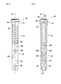
- FIG 3 a further embodiment of the bone screw 20 is shown.
- This screw 20 has differently shaped side openings 36, 37, 39 compared to the embodiment of Figure 1 .
- the openings are oriented towards the distal end to direct the flow of material into a distal direction.
- the length of the second thread 41 is shorter than the thread shown in figure 1 .
- FIG 4 a sectional view of a further embodiment of the bone screw 20 is shown.
- the different structure of the side openings 35, 36 can be seen compared to the side openings 32, 33 of Figure 2 .
- the side openings shown in this figure provide a flow of material in a slightly more distal direction compared to the previous embodiment.
- a further side opening 38, which is opposing side opening 37 is shown.
- FIG. 5 a sectional view of the distal section 13 of a preferred embodiment is shown.
- the first side opening 32 is located opposite to a second side opening 33.
- a further side opening 34 which basically has the same size as the other side openings, although it may have any different size.
- the side openings 32, 33 have heights 61, 62.
- Reference sign 63 denotes the width of the channel 30, which is identical to the diameter of the distal opening 31 in this embodiment. It is obvious that the cross-section of two opposing side openings 32, 33 given by the heights 61, 62 and the width 63 is significantly larger than the cross-section of the channel in a distal direction given by its diameter 64. This allows controlled sideward flow through the side openings and a minimal flow of material through the lumen 30, as will be shown later in detail.
- FIG 6 a further detail of section A-A of figure 6 is shown.
- the outer sides of the side openings 32, 33 form cutting edges 71, 72 which cut off the bone cement when rotating the bone screw for example for removal. These cutting edges significantly reduce the removal torque of the screw and help to avoid severe damage of the bone material.
- the angles 73, 74 of the cutting edges are less than 90° to achieve maximum cutting efficiency.
- the cutting edges 71 and 72 are most important, as these have the first contact with the material inside the opening when rotating the screw counterclockwise for removal.
- angles of less than 90 degrees may be obtained by offsetting the center axis 75, 76 of the openings 32, 33 to the center axis of the screw, so that the axis do not cross.
- angles 73, 74 can be defined between the tangents 77, 78 to the inner wall of the channel 30 and the leading edges of the body of the screw intersecting at the points 71, 72. This embodiment applies to a screw which has to be turned counterclockwise for removal.
- FIG. 7 a sectional view of the distal section of further embodiment is shown.
- the side openings 35, 36, 38 have a slightly different direction.
- the cross-sections determined by the dimensions 61, 62, 63 of the side openings are larger than the cross-section 64 of the channel 30.
- FIG 8 an example of the flow of material like bone cement into the bone 100 is shown. Due to the shape of the side openings 32, 33 of bone screw 10, certain areas of the bone are penetrated by a material like bone cement. There is a first penetration area, which is supplied by the distal opening 31. A second and third penetration area 82 and 83 is supplied by the side openings 32 and 33. Preferably, the penetration areas overlap to achieve an additional solidification. Due to the distal opening 31, for achieving a first central penetration area, an additional retention force of the bone screw can be obtained. This is significantly enlarged by connecting the penetration areas 82 and 83.
- first material is injected through the distal opening 31 by placing a sleeve 50 as shown later in close proximity to the distal opening. In the next step, the sleeve is slightly retracted for delivery of material through the side openings close to the distal opening.
- FIG 9 a top view of the bone penetration areas is shown.
- the enhanced bone penetration and the connection of the penetration areas 82 and 83 by the central penetration area 81 can clearly be seen.
- a material feeding tool like a sleeve 50 is shown.
- This sleeve may be inserted into bone screw 10 or 20. It may bear at least one marker 52 for indicating the position of the sleeve relative to the screw when inserted into the screw and therefore positioning the sleeve into the channel 30 of the bone screw.
- a sleeve 50 inserted into a bone screw 10 is shown.
- the sleeve may be moved into the direction indicated by arrow 51 and pushed into the lumen or pulled outside to place the end of the sleeve at any desired position, preferably close to any desired opening.
- the flow of material may be directed through the distal opening or any side openings.
- the indication of the height may be given by the markers 52.
- Any material, preferably a bone cement may be supplied through the sleeve into the bone screw.
- the flow is indicated by arrows 53,054, 55.
- side flows 53 and 54 are significantly larger than the center flow 54. This allows a selective supply of material through individual side holes, where needed.
- a preferred method may be first supplying bone cement through the distal section holes, and later supplying materials to remote holes in the center section.
- other holes lying between the holes being used for supplying material to the bone may be unused. This may be the case, if there are solid bone segments and no fractured segments around the screw.
- FIG 12 an embodiment with a plurality of side openings is shown.
- the proximal section and the distal section are similar to the embodiment of figure 3 .
- the center section has further side openings 90, 91 and 92.
- Below the latter side openings is another threaded section 94.
- FIG 13 the above embodiment is shown in a sectional view.
- a further side opening 94 which is opposing side opening 92, is shown.
- FIG 14 another preferred embodiment with a plurality of side openings in the distal section is shown.
- the side openings (101-106) are oriented into varying directions to allow for complete surrounding penetration of the material into the bone.
- FIG 15 the above embodiment is shown in a sectional view. Here some pairs of opposing side openings (35, 46; 105, 104) are shown.
- Figure 16 a humerus head 100 is shown with a bone plate 150 attached by the means of bone screws 10 and standard bone screws 110 is shown.
Abstract
A bone screw for connecting fractured bone segments or holding a bone plate to a bone has a hollow channel for the delivery of bone cement. It furthermore has a threaded proximal section with a means for attaching a driving tool. Next to the proximal section is a threaded center section with a cylindrical shape having a smaller diameter than the proximal section, and a second thread with a different pitch. At the end of the screw, there is an unthreaded distal section with a plurality of side opening. The side openings have a conical shape forming a cutting edge with an edge angle of less than 90 degrees for simplified removal of the screw. For a controlled injection of bone cement, resulting in a better stability, there are pairs of two side openings at opposite sides of the channel, which have a larger cross-section than the channel in a distal direction. For further improving the stability, a distal opening is provided at the end of the distal section and at least two side openings are provided in close proximity to the distal opening.
Description
- The invention relates to orthopedic devices used to reinforce bones in mammals. It specifically relates to cannulated bone screws.
- Bone screws are used to reinforce bones by connecting at least two sections of a bone and/or by holding bone plates or other parts to a bone. It is often desirable to deliver medication and/or reinforcing material into the bone. A reinforcing material may be any kind of bone cement or bone graft or any other similar material. Specifically, delivery of bone cement into a bone material in close proximity of a bone screw may increase the mechanical retention of the bone screw within the bone material.
- Cannulated bone screws are known from
US 6,048,343 . The screw has a bore forming a central channel connected to sideward channels for delivering of bone cement into the bone surrounding the screw. A sealed adaptor is provided for connecting the screw to a dispensing device. - A further bone screw having a central channel is disclosed in
US 7,608,097 B2 . A sleeve comprising a close distal end can be inserted into the screw for selective delivering of a fluid to individual side holes connected to the central channel. - A further bone screw is disclosed in
EP 1 210 019 B2 . The screw has an inner bore connected to at least one sideward channel. The bore has a closed end so that no bone cement can penetrate through the tip of the screw. - The problem to be solved by the invention is to provide a bone screw, which has a channel or lumen for the delivery of a material like medication, therapeutic fluid or any kind of bone cement or strengthening material. The bone screw should provide an increased retention force and a decreased removal torque, which allows a removal of the screw without further damaging the bone structure. Another object of the invention is to provide a bone screw, which allows a selective delivery of material at selected positions of the screw. For simplifying the selective application, a specific tool should be provided. Another problem to be solved is to improve a method for fastening a bone plate to a bone and/or to reinforce a bone by using a bone screw.
- Solutions of the problem are described in the independent claims. The dependent claims relate to further improvements of the invention.
- In a first embodiment, a bone screw has a proximal section, a center section, and an unthreaded distal section. The proximal section has an approximately cylindrical shape with a first thread. In an alternate embodiment, it may have a conical shape having a first thread. This proximal section is intended for interfacing with a bone plate, which can be attached by means of the screw to the surface of a bone. The screw may also be used for fixing or holding bone parts together, without using a bone plate. Furthermore, the proximal section has at least one means for driving the screw.
- Next to the proximal section is a center section. The center section preferably has a roughly cylindrical shape and it preferably has a second thread. The diameter of the center section preferably is smaller than the diameter of the proximal threaded section. Preferably, the pitch of the second thread of the center section is larger than the pitch of the first thread of the proximal threaded section. This difference in pitches allows for tightly fixing a bone plate to a bone or for tying at least two bone fragments together. Alternatively, both pitches may be similar. At the distal side of the second thread, there may be at least one cutout for simplifying cutting of the thread into the bone. The center section may bear at least one or a plurality of sideward holes, which allow the flow of material from the channel or lumen into the bone.
- Next to the center, section is a distal section. This distal section preferably is unthreaded, preferably has an approximately cylindrical shape, and preferably has a centered distal opening, connected to the channel of the screw, for delivering material into the bone at the distal side. It may have further sideward oriented holes for delivering material into the bone. The distal section preferably has the same diameter as the center section. Preferably, it is unthreaded. The distal section may have a closed end without a distal opening.
- Within the proximal threaded section, the center section, and the distal section, a channel or lumen is provided. Preferably, this channel has a circular cross section. It preferably has a constant diameter. This channel is connected to the sideward openings and to the distal opening of the distal section. It is further connected to a proximal opening at the proximal end of the screw. The channel may be used to deliver any material, for example a bone cement (permanent or bio resorbable) or a medication into the surrounding bone material.
- Preferably, the side openings, which are provided in the center section and/or distal section, are provided by pairs resulting in through-holes through the screw. Therefore, preferably two side openings are oriented at a 180° angle with respect to each other in a plane perpendicular to the center axis of the screw. In an alternative embodiment, there may be three or more side openings in the same plane. Preferably, at least one opening has an elongated shape with respect to the center axis. It preferably has an elliptical shape. Due to the larger extension or size of the opening parallel to the center axis, a larger total cross section of the opening can be achieved, without significantly weakening the structure of the screw. It is further preferred if there is at least one cutting edge at at least one of the side openings. This cutting edge allows cutting of the material or bone cement when removing the screw by rotating preferably counter-clockwise. Most preferably, the angle of the cutting edge is less than 90 degrees. Most preferably, at least one of the side openings has a conical shape with increasing diameter towards the outside of the screw. This allows to form a cutting edge and to further increase the cross section for delivery of material into the bone.
- The openings may be oriented into specific directions for directing the flow of material into the bone. Preferably, they are oriented orthogonally to the center axis or towards the distal end to direct the flow of material into a distal direction.
- A further embodiment relates to a tool, preferably a sleeve, which allows selective delivery of material into the bone surrounding the screw. The tool preferably has a hollow shaft and most preferably a cylindrical shaft defining an inner channel for delivery of material. The outer diameter of the sleeve is adapted to fit into the channel of the bone screw. The sleeve may be inserted into different positions, which are in proximity to the distal opening or to any specific side opening to allow selective delivery of material into the surrounding bone. For precise adjustment of the insertion depth of the sleeve into the bone screw, there may be markers preferably at the outside of the sleeve. There may be any other measuring tool for indicating the depth and/or the position of the sleeve inserted into the bone screw. Preferably the markers indicate the positions of the sleeve close to specific openings for delivering material through these openings. As there are preferably two openings at opposite sides of the lumen of the bone screw, the cross-section pointing outwards into the bone through the side opening preferably is larger than the cross-section through the lumen of the bone screw. This will result in a significantly larger side flow, sideward through the side openings compared to the center flow through the remaining channel of the bone screw. This allows selective application of material to the bone. For example, material may be supplied through openings in the center section without filling the openings in the distal section. This allows the application of bone cement where needed. Such a selective application of bone cement simplifies later removal of the screw.
- Another embodiment relates to a tool kit comprising at least one bone screw as described herein and at least one tool which may be a sleeve as described herein. At least one sleeve is adapted to fit into the channel of at least one screw. Furthermore, it is preferred if the markers at the outside of the at least one sleeve are adapted to the at least one screw.
- A further aspect of the invention relates to a method for fixing a bone screw as described herein to a bone. It comprises the steps of drilling a hole into the bone, screwing the screw by rotation of the screw into the hole, inserting a sleeve into the channel of the screw, positioning of the sleeve into close proximity to at least one desired opening and feeding a material through the sleeve via the screw into the bone. Another aspect of the invention relates to an improved method for selectively supplying material like bone cement through a bone screw. It comprises the steps of inserting a sleeve into the channel of the screw, positioning of the sleeve into close proximity to at least one desired opening and feeding a material through the sleeve via the screw into the bone. Another aspect of the invention relates to improving a method for fixing bone fragments and/or fixing a bone plate to a bone, preferably a humerus by fixing a screw as disclosed herein to the bone and/or the bone fragments and/or the bone plate. The process of delivering material may comprise the steps of delivering contrast agent for X-ray imaging, delivering of a rinsing solution which may comprise NaCl and finally delivering a bone cement.
- In the following, the invention will be described by way of example, without limitation of the general inventive concept, on examples of embodiment with reference to the drawings.
-
Figure 1 shows a preferred embodiment of a bone screw. -
Figure 2 shows a sectional view of the preferred embodiment. -
Figure 3 shows a further embodiment of the bone screw. -
Figure 4 shows a sectional view of a further embodiment. -
Figure 5 shows a sectional view of the distal section of a preferred embodiment. -
Figure 6 shows a further sectional view of the preferred embodiment. -
Figure 7 shows a sectional view of the distal section of another embodiment. -
Figure 8 shows the flow of material through the openings of the bone screw. -
Figure 9 shows a top view of the bone penetration areas. -
Figure 10 shows a material feeding sleeve. -
Figure 11 shows a sleeve inserted into a bone screw. -
Figure 12 shows a further embodiment with a plurality of side openings. -
Figure 13 shows a sectional view of the previous embodiment. -
Figure 14 shows another preferred embodiment with a plurality of side openings. -
Figure 15 shows a sectional view of the previous preferred embodiment. -
Figure 16 shows a humerus head with a bone plate attached by means of the bone screws. - In
Figure 1 , a preferred embodiment of abone screw 10 is shown. Thebone screw 10 has a preferably threadedproximal section 11, acenter section 12, and adistal section 13. It has acenter axis 19. Theproximal section 11 is preferably approximately cylindrically shaped. It may also have a conical shape to simplify insertion. Theproximal section 11 has a firstouter thread 40, which is preferably designed to interface with abone plate 150 as shown in a later figure. Thecenter section 12 preferably has a cylindrical shape and is at least partially threaded with asecond thread 41. The second thread may have at least onecutout 44 to improve cutting of the thread into the bone material when inserting the screw. Preferably, the pitch of thefirst thread 40 is less than the pitch of thesecond thread 41 to allow pressing of abone 150 plate interfacing with thefirst thread 40 to a bone interfacing with thesecond thread 41. Thedistal section 13 is preferably unthreaded and has at least oneside opening - In
Figure 2 , a sectional view of the preferred embodiment is shown. Thebone screw 10 has a channel orlumen 30, which proximately is centered to thecenter axis 19. Thechannel 30 passes through theproximal section 11, thecenter section 12, and thedistal section 13. It ends with adistal opening 31 at thedistal section 13. Furthermore, it is connected to at least oneside opening means 42 for attaching a driving tool is provided for interfacing with a screwdriver, a wrench or any other tool. - In
Figure 3 , a further embodiment of thebone screw 20 is shown. Thisscrew 20 has differently shapedside openings Figure 1 . Here, the openings are oriented towards the distal end to direct the flow of material into a distal direction. Furthermore, the length of thesecond thread 41 is shorter than the thread shown infigure 1 . Although there are preferred embodiments, any of the parts like threads or side openings shown in this document can be combined without any limitation. - In
Figure 4 , a sectional view of a further embodiment of thebone screw 20 is shown. Here, the different structure of theside openings side openings Figure 2 . The side openings shown in this figure provide a flow of material in a slightly more distal direction compared to the previous embodiment. Here afurther side opening 38, which is opposingside opening 37 is shown. - In
Figure 5 , a sectional view of thedistal section 13 of a preferred embodiment is shown. Thefirst side opening 32 is located opposite to asecond side opening 33. Above theside openings further side opening 34, which basically has the same size as the other side openings, although it may have any different size. - The
side openings heights Reference sign 63 denotes the width of thechannel 30, which is identical to the diameter of thedistal opening 31 in this embodiment. It is obvious that the cross-section of two opposingside openings heights width 63 is significantly larger than the cross-section of the channel in a distal direction given by itsdiameter 64. This allows controlled sideward flow through the side openings and a minimal flow of material through thelumen 30, as will be shown later in detail. - In
figure 6 , a further detail of section A-A offigure 6 is shown. The outer sides of theside openings form cutting edges angles center axis openings angles tangents channel 30 and the leading edges of the body of the screw intersecting at thepoints - In
Figure 7 , a sectional view of the distal section of further embodiment is shown. Here, theside openings dimensions cross-section 64 of thechannel 30. - In
Figure 8 , an example of the flow of material like bone cement into thebone 100 is shown. Due to the shape of theside openings bone screw 10, certain areas of the bone are penetrated by a material like bone cement. There is a first penetration area, which is supplied by thedistal opening 31. A second andthird penetration area side openings distal opening 31, for achieving a first central penetration area, an additional retention force of the bone screw can be obtained. This is significantly enlarged by connecting thepenetration areas distal opening 31 by placing asleeve 50 as shown later in close proximity to the distal opening. In the next step, the sleeve is slightly retracted for delivery of material through the side openings close to the distal opening. - In
Figure 9 , a top view of the bone penetration areas is shown. Here, the enhanced bone penetration and the connection of thepenetration areas central penetration area 81 can clearly be seen. - In
Figure 10 , a material feeding tool like asleeve 50 is shown. This sleeve may be inserted intobone screw marker 52 for indicating the position of the sleeve relative to the screw when inserted into the screw and therefore positioning the sleeve into thechannel 30 of the bone screw. - In
Figure 11 , asleeve 50 inserted into abone screw 10 is shown. The sleeve may be moved into the direction indicated byarrow 51 and pushed into the lumen or pulled outside to place the end of the sleeve at any desired position, preferably close to any desired opening. By this, the flow of material may be directed through the distal opening or any side openings. The indication of the height may be given by themarkers 52. Any material, preferably a bone cement may be supplied through the sleeve into the bone screw. The flow is indicated by arrows 53,054, 55. There are side flows 53, 54 through the side openings and afurther center flow 55 into the direction of thechannel 30. Due to the larger cross-section of the side openings, side flows 53 and 54 are significantly larger than thecenter flow 54. This allows a selective supply of material through individual side holes, where needed. A preferred method may be first supplying bone cement through the distal section holes, and later supplying materials to remote holes in the center section. Here, other holes lying between the holes being used for supplying material to the bone may be unused. This may be the case, if there are solid bone segments and no fractured segments around the screw. - In
figure 12 , an embodiment with a plurality of side openings is shown. The proximal section and the distal section are similar to the embodiment offigure 3 . The center section hasfurther side openings section 93 between theside openings 92 and theside openings section 94. There may be any combination of any one of the side openings shown in here with or without threaded sections in between. In general, there are only openings in unthreaded sections. - In
figure 13 , the above embodiment is shown in a sectional view. Here afurther side opening 94, which is opposingside opening 92, is shown. - In
figure 14 , another preferred embodiment with a plurality of side openings in the distal section is shown. The side openings (101-106) are oriented into varying directions to allow for complete surrounding penetration of the material into the bone. - In
figure 15 , the above embodiment is shown in a sectional view. Here some pairs of opposing side openings (35, 46; 105, 104) are shown InFigure 16 , ahumerus head 100 is shown with abone plate 150 attached by the means of bone screws 10 and standard bone screws 110 is shown. - In this example, there is a fracture of the humerus head, which requires the use of bone screws 10, having a lumen and delivering cement through the lumen of the bone screws to further stabilize the fractured humerus head. The bone shaft is not fractured, therefore
regular screws 110 may be used to further hold the bone plate to the bone. -
- 10
- bone screw
- 11
- proximal section
- 12
- center section
- 13
- distal section
- 19
- center axis
- 20
- bone screw
- 30
- channel
- 31
- distal opening
- 32 - 39
- side openings
- 40
- first thread
- 41
- second thread
- 42
- means for attaching the driving tool
- 44
- cutout
- 50
- tool
- 51
- movement of tool
- 52
- markers
- 53, 54
- side flows
- 55
- center flow
- 58
- distal end of sleeve
- 61, 62
- side opening height
- 63
- side opening width
- 64
- channel diameter
- 71, 72
- cutting edges
- 73, 74
- cutting edge angles
- 75, 76
- opening axis
- 77, 78
- tangent to channel
- 80 - 82
- bone penetration areas
- 90, 91
- further side openings
- 93, 94
- further threaded sections
- 100
- bone
- 150
- bone plate
Claims (15)
- Bone screw (10) having a hollow channel (30) and a center axis (19) defined by said channel with at least- a proximal section (11) with a first thread (40) and a means (42) for attaching a driving tool,- a center section (12) with a cylindrical shape having a smaller diameter than the proximal section, further having a second thread (41),- a distal section (13) with at least one side opening (32-39),characterized in, that
at least one cutting edge (71, 72) having an edge angle of less than 90 degrees is provided at at least one of the side openings (32 - 39). - Bone screw (10) having a hollow channel (30) and a center axis (19) defined by said channel with at least- a proximal section (11) with a first thread (40) and a means (42) for attaching a driving tool,- a center section (12) with a cylindrical shape having a smaller diameter than the proximal section, further having a second thread (41),- a distal section (13) with at least one side opening (32-39),characterized in, that
at least two side openings (32 - 39) are provided within a plane under a right angle to the center axis, and the sum of cross-sections of the at least two side openings is larger than the cross section of the hollow channel (30) in a distal direction. - Bone screw (10) having a hollow channel (30) and a center axis (19) defined by said channel with at least- a proximal section (11) with a first thread (40) and a means (42) for attaching a driving tool,- a center section (12) with a cylindrical shape having a smaller diameter than the proximal section, further having a second thread (41),- a distal section (13) preferably having no thread with at least one side opening (32-39),characterized in, that
a distal opening (31) is provided at the end of the distal section and at least two side openings (32, 33, 35, 36) are provided in close proximity to the distal opening. - Bone screw having the features of claim 1 and/or claim 2 and/or claim 3.
- Bone screw according to claim 2,
characterized in, that
at least two side openings are at opposite sides of the hollow channel. - Bone screw according to any one of the preceding claims,
characterized in, that
the second thread (41) at the center section (12) has at least one cutout (44). - Bone screw according to any one of the preceding claims,
characterized in, that
the distal section (13) has a center distal opening (31). - Bone screw according to any one of the preceding claims,
characterized in, that
a cutout (44) is provided in the second thread (41). - Bone screw according to any one of the preceding claims,
characterized in, that
the pitch of the second thread (41) is larger than or similar to the pitch of the first thread (40). - Bone screw according to any one of the preceding claims,
characterized in, that
at least one of the side openings has a conical shape. - Bone screw according to any one of the preceding claims,
characterized in, that
at least one of the side openings has an elliptical shape. - Bone screw according to any one of the preceding claims,
characterized in, that
at least one of the side openings is oriented distally. - Bone screw according to any one of the preceding claims,
characterized in, that
at least one of the side openings 32, 33 has a center axis 75, 76 which does not cross the center axis 19 of the bone screw. - Tool kit comprising at least one bone screw (10) according to any one of the preceding claims and at least one tool (50) having a hollow shaft which fits into the hollow channel (19) of the at least one bone screw.
- Tool kit according to claim 14,
characterized in, that
the at least one tool (50) has at least one marker (52) for indicating the depth of the tool within the screw when inserted into the screw.
Priority Applications (9)
| Application Number | Priority Date | Filing Date | Title |
|---|---|---|---|
| EP13187609.6A EP2856958A1 (en) | 2013-10-07 | 2013-10-07 | Cannulated bone screw |
| AU2014333902A AU2014333902B2 (en) | 2013-10-07 | 2014-10-07 | Cannulated bone screw |
| CA2925045A CA2925045A1 (en) | 2013-10-07 | 2014-10-07 | Cannulated bone screw |
| PCT/EP2014/071458 WO2015052195A1 (en) | 2013-10-07 | 2014-10-07 | Cannulated bone screw |
| CN201480055405.3A CN105611886B (en) | 2013-10-07 | 2014-10-07 | Hollow bone screw |
| EP17200709.8A EP3308728B1 (en) | 2013-10-07 | 2014-10-07 | Cannulated bone screw |
| JP2016521261A JP6195984B2 (en) | 2013-10-07 | 2014-10-07 | Cannulated bone screw |
| EP14781213.5A EP2983601B1 (en) | 2013-10-07 | 2014-10-07 | Cannulated bone screw |
| US15/093,124 US10405904B2 (en) | 2013-10-07 | 2016-04-07 | Cannulated bone screw |
Applications Claiming Priority (1)
| Application Number | Priority Date | Filing Date | Title |
|---|---|---|---|
| EP13187609.6A EP2856958A1 (en) | 2013-10-07 | 2013-10-07 | Cannulated bone screw |
Publications (1)
| Publication Number | Publication Date |
|---|---|
| EP2856958A1 true EP2856958A1 (en) | 2015-04-08 |
Family
ID=49303850
Family Applications (3)
| Application Number | Title | Priority Date | Filing Date |
|---|---|---|---|
| EP13187609.6A Withdrawn EP2856958A1 (en) | 2013-10-07 | 2013-10-07 | Cannulated bone screw |
| EP17200709.8A Active EP3308728B1 (en) | 2013-10-07 | 2014-10-07 | Cannulated bone screw |
| EP14781213.5A Active EP2983601B1 (en) | 2013-10-07 | 2014-10-07 | Cannulated bone screw |
Family Applications After (2)
| Application Number | Title | Priority Date | Filing Date |
|---|---|---|---|
| EP17200709.8A Active EP3308728B1 (en) | 2013-10-07 | 2014-10-07 | Cannulated bone screw |
| EP14781213.5A Active EP2983601B1 (en) | 2013-10-07 | 2014-10-07 | Cannulated bone screw |
Country Status (7)
| Country | Link |
|---|---|
| US (1) | US10405904B2 (en) |
| EP (3) | EP2856958A1 (en) |
| JP (1) | JP6195984B2 (en) |
| CN (1) | CN105611886B (en) |
| AU (1) | AU2014333902B2 (en) |
| CA (1) | CA2925045A1 (en) |
| WO (1) | WO2015052195A1 (en) |
Families Citing this family (28)
| Publication number | Priority date | Publication date | Assignee | Title |
|---|---|---|---|---|
| US8388624B2 (en) | 2003-02-24 | 2013-03-05 | Arthrosurface Incorporated | Trochlear resurfacing system and method |
| EP2136717B1 (en) | 2006-12-11 | 2013-10-16 | Arthrosurface Incorporated | Retrograde resection apparatus |
| WO2016154393A1 (en) | 2009-04-17 | 2016-09-29 | Arthrosurface Incorporated | Glenoid repair system and methods of use thereof |
| WO2010121250A1 (en) | 2009-04-17 | 2010-10-21 | Arthrosurface Incorporated | Glenoid resurfacing system and method |
| EP2542165A4 (en) | 2010-03-05 | 2015-10-07 | Arthrosurface Inc | Tibial resurfacing system and method |
| EP2804565B1 (en) | 2011-12-22 | 2018-03-07 | Arthrosurface Incorporated | System for bone fixation |
| WO2014008126A1 (en) | 2012-07-03 | 2014-01-09 | Arthrosurface Incorporated | System and method for joint resurfacing and repair |
| US9492200B2 (en) | 2013-04-16 | 2016-11-15 | Arthrosurface Incorporated | Suture system and method |
| US9962265B2 (en) | 2014-03-07 | 2018-05-08 | Arthrosurface Incorporated | System and method for repairing articular surfaces |
| US11607319B2 (en) | 2014-03-07 | 2023-03-21 | Arthrosurface Incorporated | System and method for repairing articular surfaces |
| US10624748B2 (en) | 2014-03-07 | 2020-04-21 | Arthrosurface Incorporated | System and method for repairing articular surfaces |
| WO2017041065A1 (en) * | 2015-09-04 | 2017-03-09 | Centric Medical Llc (A Delaware Limited Liability Company) | Small bone orthopedic implants |
| USD846977S1 (en) | 2016-05-12 | 2019-04-30 | Innovate Orthopaedics Limited | Screw |
| US11389205B2 (en) | 2016-11-30 | 2022-07-19 | Stryker European Operations Holdings Llc | Spinal fastener with serrated thread |
| US11540866B2 (en) | 2017-03-29 | 2023-01-03 | Bone Solutions, Inc. | Implant of osteostimulative material |
| USD898196S1 (en) * | 2017-07-10 | 2020-10-06 | Stryker European Holdings I, Llc | Spinal fastener with serrated thread |
| WO2019028344A1 (en) | 2017-08-04 | 2019-02-07 | Arthrosurface Incorporated | Multicomponent articular surface implant |
| US11191645B2 (en) * | 2017-09-05 | 2021-12-07 | ExsoMed Corporation | Small bone tapered compression screw |
| US11147681B2 (en) | 2017-09-05 | 2021-10-19 | ExsoMed Corporation | Small bone angled compression screw |
| US20190125420A1 (en) * | 2017-10-31 | 2019-05-02 | Bone Solutions, Inc. | Bioabsorbable Composite Screw |
| US10888363B2 (en) | 2017-12-06 | 2021-01-12 | Stout Medical Group, L.P. | Attachment device and method for use |
| US20200405329A1 (en) * | 2018-02-27 | 2020-12-31 | The University Of Toledo | Syndesmosis fixation and reconstruction system and method of using the same |
| USD857897S1 (en) * | 2018-03-21 | 2019-08-27 | Thomas Stuart Loftus | Bone screw |
| USD857898S1 (en) * | 2018-04-17 | 2019-08-27 | Thomas Stuart Loftus | Bone screw |
| EP3781057A1 (en) | 2018-04-18 | 2021-02-24 | GLW, Inc. | Removable orthopedic screws |
| GB2609338B (en) | 2019-03-12 | 2023-06-14 | Arthrosurface Inc | Humeral and glenoid articular surface implant systems and methods |
| US11660134B2 (en) * | 2019-06-13 | 2023-05-30 | Medos International Sarl | Instruments and methods for delivering bone cement to a bone screw |
| WO2022002468A1 (en) * | 2020-06-29 | 2022-01-06 | R3Volution D Ag | Kit comprising a custom implant and at least one other element |
Citations (8)
| Publication number | Priority date | Publication date | Assignee | Title |
|---|---|---|---|---|
| US6048343A (en) | 1999-06-02 | 2000-04-11 | Mathis; John M. | Bone screw system |
| EP1210019B1 (en) | 1999-09-08 | 2004-10-20 | SYNTHES AG Chur | Bone screw |
| US20070233123A1 (en) * | 2006-02-21 | 2007-10-04 | Osteomed, L.P. | Bone fixation device |
| US20080269893A1 (en) * | 2007-04-25 | 2008-10-30 | Jmea Corporation | Prosthesis with a Selectively Applied Bone Growth Promoting Agent |
| US7608097B2 (en) | 2003-04-29 | 2009-10-27 | Millennium Medical Technologies | Bone screw with fluid delivery structure |
| WO2011054122A1 (en) * | 2009-11-09 | 2011-05-12 | Spinewelding Ag | Medical device, apparatus, and surgical method |
| US20120053639A1 (en) * | 2010-08-27 | 2012-03-01 | Grant William P | Foot beam insert |
| US8197517B1 (en) * | 2007-05-08 | 2012-06-12 | Theken Spine, Llc | Frictional polyaxial screw assembly |
Family Cites Families (22)
| Publication number | Priority date | Publication date | Assignee | Title |
|---|---|---|---|---|
| US4449874A (en) * | 1981-12-01 | 1984-05-22 | Mckinney Blake | Self-threading bolt |
| US4636121A (en) * | 1985-04-22 | 1987-01-13 | Miller Lillias S | Holding screw |
| US5129901A (en) * | 1991-06-10 | 1992-07-14 | Decoste Vern X | Cannulated orthopedic screw |
| FR2737968B1 (en) * | 1995-08-23 | 1997-12-05 | Biomat | IMPLANT FOR OSTEOSYNTHESIS OF SUPERIOR FEMALE EPIPHYSIS |
| JPH09149906A (en) * | 1995-11-29 | 1997-06-10 | Nagoya Rashi Seisakusho:Kk | Tool for curing bone disease |
| JP3575208B2 (en) * | 1997-01-31 | 2004-10-13 | 三菱マテリアル株式会社 | Bone screw |
| GB2387633B (en) * | 2002-04-18 | 2004-02-25 | Joker Ind Co Ltd | Nail anchor |
| US7338493B1 (en) * | 2002-06-28 | 2008-03-04 | Biomet Manufacturing Corp. | Method and apparatus for cementing a screw anchor |
| US7776042B2 (en) * | 2002-12-03 | 2010-08-17 | Trans1 Inc. | Methods and apparatus for provision of therapy to adjacent motion segments |
| WO2004093637A2 (en) * | 2003-04-17 | 2004-11-04 | Secant Medical, Llc | Tool with deployable cutting blade |
| DE202006012964U1 (en) * | 2006-06-13 | 2006-10-19 | Brehm, Peter | Connecting element for joining and reinforcing bone material comprises a shaft, a head, a fixing unit arranged on the shaft for fixing the shaft to bone material, a longitudinal channel and a lateral outlet opening |
| US8556947B2 (en) * | 2007-07-13 | 2013-10-15 | Stryker Trauma Gmbh | Device for fixation of bone fractures |
| US8257407B2 (en) * | 2008-04-23 | 2012-09-04 | Aryan Henry E | Bone plate system and method |
| US20110213426A1 (en) * | 2009-04-20 | 2011-09-01 | Yedlicka Joseph W | System and method for self filling bone screws |
| US8574273B2 (en) * | 2009-09-09 | 2013-11-05 | Innovision, Inc. | Bone screws and methods of use thereof |
| WO2013000071A1 (en) * | 2011-06-28 | 2013-01-03 | Spinologics Inc. | Bone screw, and bone fixation system and method |
| US20130211466A1 (en) * | 2012-02-15 | 2013-08-15 | Warsaw Orthopedic, Inc. | Bone fastener and methods of use |
| US9782209B2 (en) * | 2012-10-03 | 2017-10-10 | Rtg Scientific | Medical fastener |
| US9526547B2 (en) * | 2013-03-06 | 2016-12-27 | Rgt Scientific Inc. | Bone screw |
| US10548651B2 (en) * | 2013-03-15 | 2020-02-04 | Nicholas Poulos | Self-drilling, self-tapping bone screw |
| EP3326552B1 (en) * | 2013-04-24 | 2023-02-22 | T.A.G. Medical Devices - Agriculture Cooperative Ltd. | Bone material removal devices |
| CN104665913B (en) * | 2013-11-26 | 2017-06-06 | 财团法人工业技术研究院 | Bionic fixing device and pulling-out device thereof |
-
2013
- 2013-10-07 EP EP13187609.6A patent/EP2856958A1/en not_active Withdrawn
-
2014
- 2014-10-07 AU AU2014333902A patent/AU2014333902B2/en active Active
- 2014-10-07 CA CA2925045A patent/CA2925045A1/en not_active Abandoned
- 2014-10-07 JP JP2016521261A patent/JP6195984B2/en active Active
- 2014-10-07 EP EP17200709.8A patent/EP3308728B1/en active Active
- 2014-10-07 CN CN201480055405.3A patent/CN105611886B/en active Active
- 2014-10-07 WO PCT/EP2014/071458 patent/WO2015052195A1/en active Application Filing
- 2014-10-07 EP EP14781213.5A patent/EP2983601B1/en active Active
-
2016
- 2016-04-07 US US15/093,124 patent/US10405904B2/en active Active
Patent Citations (8)
| Publication number | Priority date | Publication date | Assignee | Title |
|---|---|---|---|---|
| US6048343A (en) | 1999-06-02 | 2000-04-11 | Mathis; John M. | Bone screw system |
| EP1210019B1 (en) | 1999-09-08 | 2004-10-20 | SYNTHES AG Chur | Bone screw |
| US7608097B2 (en) | 2003-04-29 | 2009-10-27 | Millennium Medical Technologies | Bone screw with fluid delivery structure |
| US20070233123A1 (en) * | 2006-02-21 | 2007-10-04 | Osteomed, L.P. | Bone fixation device |
| US20080269893A1 (en) * | 2007-04-25 | 2008-10-30 | Jmea Corporation | Prosthesis with a Selectively Applied Bone Growth Promoting Agent |
| US8197517B1 (en) * | 2007-05-08 | 2012-06-12 | Theken Spine, Llc | Frictional polyaxial screw assembly |
| WO2011054122A1 (en) * | 2009-11-09 | 2011-05-12 | Spinewelding Ag | Medical device, apparatus, and surgical method |
| US20120053639A1 (en) * | 2010-08-27 | 2012-03-01 | Grant William P | Foot beam insert |
Also Published As
| Publication number | Publication date |
|---|---|
| US20160213413A1 (en) | 2016-07-28 |
| JP2016532471A (en) | 2016-10-20 |
| AU2014333902B2 (en) | 2018-03-15 |
| EP2983601B1 (en) | 2017-11-22 |
| EP3308728A1 (en) | 2018-04-18 |
| AU2014333902A1 (en) | 2016-04-14 |
| CN105611886A (en) | 2016-05-25 |
| CA2925045A1 (en) | 2015-04-16 |
| US10405904B2 (en) | 2019-09-10 |
| WO2015052195A1 (en) | 2015-04-16 |
| EP2983601A1 (en) | 2016-02-17 |
| EP3308728B1 (en) | 2019-11-20 |
| JP6195984B2 (en) | 2017-09-13 |
| CN105611886B (en) | 2019-03-08 |
Similar Documents
| Publication | Publication Date | Title |
|---|---|---|
| EP2983601B1 (en) | Cannulated bone screw | |
| US20070233123A1 (en) | Bone fixation device | |
| US7608097B2 (en) | Bone screw with fluid delivery structure | |
| US6214012B1 (en) | Method and apparatus for delivering material to a desired location | |
| ES2357432T3 (en) | DEVICE FOR THE SETTING OF BONE FRACTURES. | |
| US10271882B2 (en) | Bone screw | |
| EP3527146B1 (en) | Surgical fastener | |
| US9603644B2 (en) | Methods and devices for delivery of medicine to bone | |
| US20130184765A1 (en) | Multi-axial bone plate fixation | |
| US20110196372A1 (en) | Bone Fixing Material and Thighbone Fixing System | |
| EP2329781B1 (en) | Bone screw | |
| US8419779B2 (en) | Systematic displacement bone screw | |
| KR20120084663A (en) | Triple lead bone screw | |
| US9517075B2 (en) | Drill bit and method for preparing a bone for a fixation screw | |
| JP2021146209A (en) | Anchor delivery systems | |
| CN110680566A (en) | Bone filling prosthesis | |
| WO2009154229A1 (en) | Intramedullary nail and intramedullary nail main body | |
| CN211213693U (en) | Bone filling prosthesis | |
| EP2586393B1 (en) | Locking hole arrangement | |
| KR20030037616A (en) | Free length hip pin |
Legal Events
| Date | Code | Title | Description |
|---|---|---|---|
| PUAI | Public reference made under article 153(3) epc to a published international application that has entered the european phase |
Free format text: ORIGINAL CODE: 0009012 |
|
| 17P | Request for examination filed |
Effective date: 20131007 |
|
| AK | Designated contracting states |
Kind code of ref document: A1 Designated state(s): AL AT BE BG CH CY CZ DE DK EE ES FI FR GB GR HR HU IE IS IT LI LT LU LV MC MK MT NL NO PL PT RO RS SE SI SK SM TR |
|
| AX | Request for extension of the european patent |
Extension state: BA ME |
|
| STAA | Information on the status of an ep patent application or granted ep patent |
Free format text: STATUS: THE APPLICATION IS DEEMED TO BE WITHDRAWN |
|
| 18D | Application deemed to be withdrawn |
Effective date: 20151009 |