EP2856973A1 - Catheter system for introducing an expandable heart valve stent into the body of a patient - Google Patents
Catheter system for introducing an expandable heart valve stent into the body of a patient Download PDFInfo
- Publication number
- EP2856973A1 EP2856973A1 EP20140179639 EP14179639A EP2856973A1 EP 2856973 A1 EP2856973 A1 EP 2856973A1 EP 20140179639 EP20140179639 EP 20140179639 EP 14179639 A EP14179639 A EP 14179639A EP 2856973 A1 EP2856973 A1 EP 2856973A1
- Authority
- EP
- European Patent Office
- Prior art keywords
- catheter
- tube
- stent
- sleeve
- section
- Prior art date
- Legal status (The legal status is an assumption and is not a legal conclusion. Google has not performed a legal analysis and makes no representation as to the accuracy of the status listed.)
- Granted
Links
- 210000003709 heart valve Anatomy 0.000 title claims abstract description 136
- 238000003780 insertion Methods 0.000 claims description 165
- 230000037431 insertion Effects 0.000 claims description 164
- 239000000463 material Substances 0.000 claims description 54
- 238000002513 implantation Methods 0.000 claims description 42
- 210000000709 aorta Anatomy 0.000 claims description 26
- 210000002376 aorta thoracic Anatomy 0.000 claims description 21
- 239000012530 fluid Substances 0.000 claims description 16
- 230000007704 transition Effects 0.000 claims description 14
- 230000033001 locomotion Effects 0.000 claims description 13
- 238000002347 injection Methods 0.000 claims description 11
- 239000007924 injection Substances 0.000 claims description 11
- 239000012781 shape memory material Substances 0.000 claims description 9
- 210000005166 vasculature Anatomy 0.000 claims description 8
- 238000010276 construction Methods 0.000 claims description 5
- 229920002614 Polyether block amide Polymers 0.000 claims description 4
- 230000002787 reinforcement Effects 0.000 claims description 3
- 239000004677 Nylon Substances 0.000 claims description 2
- 229920001778 nylon Polymers 0.000 claims description 2
- 229920001296 polysiloxane Polymers 0.000 claims description 2
- 229920002635 polyurethane Polymers 0.000 claims description 2
- 239000004814 polyurethane Substances 0.000 claims description 2
- 239000004800 polyvinyl chloride Substances 0.000 claims description 2
- 230000005540 biological transmission Effects 0.000 description 29
- 238000006073 displacement reaction Methods 0.000 description 27
- 238000000034 method Methods 0.000 description 24
- 239000000945 filler Substances 0.000 description 11
- 230000006835 compression Effects 0.000 description 10
- 238000007906 compression Methods 0.000 description 10
- 239000004033 plastic Substances 0.000 description 10
- 229920003023 plastic Polymers 0.000 description 10
- 210000001367 artery Anatomy 0.000 description 9
- 230000006378 damage Effects 0.000 description 9
- 239000010935 stainless steel Substances 0.000 description 9
- 229910001220 stainless steel Inorganic materials 0.000 description 9
- 238000012546 transfer Methods 0.000 description 9
- 230000007246 mechanism Effects 0.000 description 8
- 229910001000 nickel titanium Inorganic materials 0.000 description 8
- HLXZNVUGXRDIFK-UHFFFAOYSA-N nickel titanium Chemical compound [Ti].[Ti].[Ti].[Ti].[Ti].[Ti].[Ti].[Ti].[Ti].[Ti].[Ti].[Ni].[Ni].[Ni].[Ni].[Ni].[Ni].[Ni].[Ni].[Ni].[Ni].[Ni].[Ni].[Ni].[Ni] HLXZNVUGXRDIFK-UHFFFAOYSA-N 0.000 description 8
- 208000014674 injury Diseases 0.000 description 7
- 206010061996 Heart valve stenosis Diseases 0.000 description 6
- 238000005452 bending Methods 0.000 description 6
- 230000000694 effects Effects 0.000 description 6
- 206010067660 Heart valve incompetence Diseases 0.000 description 5
- 208000027418 Wounds and injury Diseases 0.000 description 5
- 210000004204 blood vessel Anatomy 0.000 description 5
- 210000001105 femoral artery Anatomy 0.000 description 5
- 238000004873 anchoring Methods 0.000 description 4
- 210000001765 aortic valve Anatomy 0.000 description 4
- 230000008901 benefit Effects 0.000 description 4
- 230000007547 defect Effects 0.000 description 4
- 230000007935 neutral effect Effects 0.000 description 4
- 230000002792 vascular Effects 0.000 description 4
- 210000003462 vein Anatomy 0.000 description 4
- 230000009471 action Effects 0.000 description 3
- 230000003446 memory effect Effects 0.000 description 3
- 230000008569 process Effects 0.000 description 3
- 238000009530 blood pressure measurement Methods 0.000 description 2
- 230000036760 body temperature Effects 0.000 description 2
- 230000008859 change Effects 0.000 description 2
- 239000002826 coolant Substances 0.000 description 2
- 238000001816 cooling Methods 0.000 description 2
- 208000037265 diseases, disorders, signs and symptoms Diseases 0.000 description 2
- 208000035475 disorder Diseases 0.000 description 2
- 238000005516 engineering process Methods 0.000 description 2
- 210000000887 face Anatomy 0.000 description 2
- 239000000835 fiber Substances 0.000 description 2
- 230000006870 function Effects 0.000 description 2
- 210000004013 groin Anatomy 0.000 description 2
- 210000003128 head Anatomy 0.000 description 2
- 210000005240 left ventricle Anatomy 0.000 description 2
- 239000007788 liquid Substances 0.000 description 2
- 230000037361 pathway Effects 0.000 description 2
- 238000000926 separation method Methods 0.000 description 2
- 239000000243 solution Substances 0.000 description 2
- 230000008733 trauma Effects 0.000 description 2
- 230000002861 ventricular Effects 0.000 description 2
- 208000003017 Aortic Valve Stenosis Diseases 0.000 description 1
- 206010002915 Aortic valve incompetence Diseases 0.000 description 1
- 101800004637 Communis Proteins 0.000 description 1
- 206010010356 Congenital anomaly Diseases 0.000 description 1
- 229910000990 Ni alloy Inorganic materials 0.000 description 1
- 208000031481 Pathologic Constriction Diseases 0.000 description 1
- FAPWRFPIFSIZLT-UHFFFAOYSA-M Sodium chloride Chemical compound [Na+].[Cl-] FAPWRFPIFSIZLT-UHFFFAOYSA-M 0.000 description 1
- 229910001069 Ti alloy Inorganic materials 0.000 description 1
- RTAQQCXQSZGOHL-UHFFFAOYSA-N Titanium Chemical compound [Ti] RTAQQCXQSZGOHL-UHFFFAOYSA-N 0.000 description 1
- 229910001080 W alloy Inorganic materials 0.000 description 1
- 230000004913 activation Effects 0.000 description 1
- 229920006125 amorphous polymer Polymers 0.000 description 1
- 210000003484 anatomy Anatomy 0.000 description 1
- 206010002906 aortic stenosis Diseases 0.000 description 1
- 201000002064 aortic valve insufficiency Diseases 0.000 description 1
- 230000001174 ascending effect Effects 0.000 description 1
- 239000008280 blood Substances 0.000 description 1
- 210000004369 blood Anatomy 0.000 description 1
- 230000017531 blood circulation Effects 0.000 description 1
- 230000023555 blood coagulation Effects 0.000 description 1
- 230000000747 cardiac effect Effects 0.000 description 1
- 210000000748 cardiovascular system Anatomy 0.000 description 1
- 238000006243 chemical reaction Methods 0.000 description 1
- 239000002131 composite material Substances 0.000 description 1
- 230000008602 contraction Effects 0.000 description 1
- 230000009849 deactivation Effects 0.000 description 1
- 230000001419 dependent effect Effects 0.000 description 1
- 238000013461 design Methods 0.000 description 1
- 230000001747 exhibiting effect Effects 0.000 description 1
- 230000002349 favourable effect Effects 0.000 description 1
- 238000011010 flushing procedure Methods 0.000 description 1
- 210000005003 heart tissue Anatomy 0.000 description 1
- 238000010438 heat treatment Methods 0.000 description 1
- 238000003384 imaging method Methods 0.000 description 1
- 239000007943 implant Substances 0.000 description 1
- 230000002452 interceptive effect Effects 0.000 description 1
- 238000004519 manufacturing process Methods 0.000 description 1
- 230000003340 mental effect Effects 0.000 description 1
- 210000004115 mitral valve Anatomy 0.000 description 1
- 239000000203 mixture Substances 0.000 description 1
- 238000012544 monitoring process Methods 0.000 description 1
- ZONODCCBXBRQEZ-UHFFFAOYSA-N platinum tungsten Chemical compound [W].[Pt] ZONODCCBXBRQEZ-UHFFFAOYSA-N 0.000 description 1
- 229920000642 polymer Polymers 0.000 description 1
- 230000002685 pulmonary effect Effects 0.000 description 1
- 210000003102 pulmonary valve Anatomy 0.000 description 1
- 229920006126 semicrystalline polymer Polymers 0.000 description 1
- 229920000431 shape-memory polymer Polymers 0.000 description 1
- 238000007493 shaping process Methods 0.000 description 1
- 239000007787 solid Substances 0.000 description 1
- 230000036262 stenosis Effects 0.000 description 1
- 208000037804 stenosis Diseases 0.000 description 1
- 239000000126 substance Substances 0.000 description 1
- 239000010936 titanium Substances 0.000 description 1
- 210000000591 tricuspid valve Anatomy 0.000 description 1
Images


Classifications
-
- A—HUMAN NECESSITIES
- A61—MEDICAL OR VETERINARY SCIENCE; HYGIENE
- A61F—FILTERS IMPLANTABLE INTO BLOOD VESSELS; PROSTHESES; DEVICES PROVIDING PATENCY TO, OR PREVENTING COLLAPSING OF, TUBULAR STRUCTURES OF THE BODY, e.g. STENTS; ORTHOPAEDIC, NURSING OR CONTRACEPTIVE DEVICES; FOMENTATION; TREATMENT OR PROTECTION OF EYES OR EARS; BANDAGES, DRESSINGS OR ABSORBENT PADS; FIRST-AID KITS
- A61F2/00—Filters implantable into blood vessels; Prostheses, i.e. artificial substitutes or replacements for parts of the body; Appliances for connecting them with the body; Devices providing patency to, or preventing collapsing of, tubular structures of the body, e.g. stents
- A61F2/02—Prostheses implantable into the body
- A61F2/24—Heart valves ; Vascular valves, e.g. venous valves; Heart implants, e.g. passive devices for improving the function of the native valve or the heart muscle; Transmyocardial revascularisation [TMR] devices; Valves implantable in the body
- A61F2/2427—Devices for manipulating or deploying heart valves during implantation
- A61F2/2436—Deployment by retracting a sheath
-
- A—HUMAN NECESSITIES
- A61—MEDICAL OR VETERINARY SCIENCE; HYGIENE
- A61F—FILTERS IMPLANTABLE INTO BLOOD VESSELS; PROSTHESES; DEVICES PROVIDING PATENCY TO, OR PREVENTING COLLAPSING OF, TUBULAR STRUCTURES OF THE BODY, e.g. STENTS; ORTHOPAEDIC, NURSING OR CONTRACEPTIVE DEVICES; FOMENTATION; TREATMENT OR PROTECTION OF EYES OR EARS; BANDAGES, DRESSINGS OR ABSORBENT PADS; FIRST-AID KITS
- A61F2/00—Filters implantable into blood vessels; Prostheses, i.e. artificial substitutes or replacements for parts of the body; Appliances for connecting them with the body; Devices providing patency to, or preventing collapsing of, tubular structures of the body, e.g. stents
- A61F2/02—Prostheses implantable into the body
- A61F2/24—Heart valves ; Vascular valves, e.g. venous valves; Heart implants, e.g. passive devices for improving the function of the native valve or the heart muscle; Transmyocardial revascularisation [TMR] devices; Valves implantable in the body
- A61F2/2412—Heart valves ; Vascular valves, e.g. venous valves; Heart implants, e.g. passive devices for improving the function of the native valve or the heart muscle; Transmyocardial revascularisation [TMR] devices; Valves implantable in the body with soft flexible valve members, e.g. tissue valves shaped like natural valves
- A61F2/2418—Scaffolds therefor, e.g. support stents
-
- A—HUMAN NECESSITIES
- A61—MEDICAL OR VETERINARY SCIENCE; HYGIENE
- A61F—FILTERS IMPLANTABLE INTO BLOOD VESSELS; PROSTHESES; DEVICES PROVIDING PATENCY TO, OR PREVENTING COLLAPSING OF, TUBULAR STRUCTURES OF THE BODY, e.g. STENTS; ORTHOPAEDIC, NURSING OR CONTRACEPTIVE DEVICES; FOMENTATION; TREATMENT OR PROTECTION OF EYES OR EARS; BANDAGES, DRESSINGS OR ABSORBENT PADS; FIRST-AID KITS
- A61F2/00—Filters implantable into blood vessels; Prostheses, i.e. artificial substitutes or replacements for parts of the body; Appliances for connecting them with the body; Devices providing patency to, or preventing collapsing of, tubular structures of the body, e.g. stents
- A61F2/02—Prostheses implantable into the body
- A61F2/24—Heart valves ; Vascular valves, e.g. venous valves; Heart implants, e.g. passive devices for improving the function of the native valve or the heart muscle; Transmyocardial revascularisation [TMR] devices; Valves implantable in the body
- A61F2/2427—Devices for manipulating or deploying heart valves during implantation
- A61F2/243—Deployment by mechanical expansion
- A61F2/2433—Deployment by mechanical expansion using balloon catheter
-
- A—HUMAN NECESSITIES
- A61—MEDICAL OR VETERINARY SCIENCE; HYGIENE
- A61F—FILTERS IMPLANTABLE INTO BLOOD VESSELS; PROSTHESES; DEVICES PROVIDING PATENCY TO, OR PREVENTING COLLAPSING OF, TUBULAR STRUCTURES OF THE BODY, e.g. STENTS; ORTHOPAEDIC, NURSING OR CONTRACEPTIVE DEVICES; FOMENTATION; TREATMENT OR PROTECTION OF EYES OR EARS; BANDAGES, DRESSINGS OR ABSORBENT PADS; FIRST-AID KITS
- A61F2/00—Filters implantable into blood vessels; Prostheses, i.e. artificial substitutes or replacements for parts of the body; Appliances for connecting them with the body; Devices providing patency to, or preventing collapsing of, tubular structures of the body, e.g. stents
- A61F2/95—Instruments specially adapted for placement or removal of stents or stent-grafts
- A61F2/9517—Instruments specially adapted for placement or removal of stents or stent-grafts handle assemblies therefor
-
- A—HUMAN NECESSITIES
- A61—MEDICAL OR VETERINARY SCIENCE; HYGIENE
- A61F—FILTERS IMPLANTABLE INTO BLOOD VESSELS; PROSTHESES; DEVICES PROVIDING PATENCY TO, OR PREVENTING COLLAPSING OF, TUBULAR STRUCTURES OF THE BODY, e.g. STENTS; ORTHOPAEDIC, NURSING OR CONTRACEPTIVE DEVICES; FOMENTATION; TREATMENT OR PROTECTION OF EYES OR EARS; BANDAGES, DRESSINGS OR ABSORBENT PADS; FIRST-AID KITS
- A61F2/00—Filters implantable into blood vessels; Prostheses, i.e. artificial substitutes or replacements for parts of the body; Appliances for connecting them with the body; Devices providing patency to, or preventing collapsing of, tubular structures of the body, e.g. stents
- A61F2/95—Instruments specially adapted for placement or removal of stents or stent-grafts
- A61F2/962—Instruments specially adapted for placement or removal of stents or stent-grafts having an outer sleeve
- A61F2/966—Instruments specially adapted for placement or removal of stents or stent-grafts having an outer sleeve with relative longitudinal movement between outer sleeve and prosthesis, e.g. using a push rod
-
- A—HUMAN NECESSITIES
- A61—MEDICAL OR VETERINARY SCIENCE; HYGIENE
- A61F—FILTERS IMPLANTABLE INTO BLOOD VESSELS; PROSTHESES; DEVICES PROVIDING PATENCY TO, OR PREVENTING COLLAPSING OF, TUBULAR STRUCTURES OF THE BODY, e.g. STENTS; ORTHOPAEDIC, NURSING OR CONTRACEPTIVE DEVICES; FOMENTATION; TREATMENT OR PROTECTION OF EYES OR EARS; BANDAGES, DRESSINGS OR ABSORBENT PADS; FIRST-AID KITS
- A61F2/00—Filters implantable into blood vessels; Prostheses, i.e. artificial substitutes or replacements for parts of the body; Appliances for connecting them with the body; Devices providing patency to, or preventing collapsing of, tubular structures of the body, e.g. stents
- A61F2/95—Instruments specially adapted for placement or removal of stents or stent-grafts
- A61F2002/9505—Instruments specially adapted for placement or removal of stents or stent-grafts having retaining means other than an outer sleeve, e.g. male-female connector between stent and instrument
-
- A—HUMAN NECESSITIES
- A61—MEDICAL OR VETERINARY SCIENCE; HYGIENE
- A61F—FILTERS IMPLANTABLE INTO BLOOD VESSELS; PROSTHESES; DEVICES PROVIDING PATENCY TO, OR PREVENTING COLLAPSING OF, TUBULAR STRUCTURES OF THE BODY, e.g. STENTS; ORTHOPAEDIC, NURSING OR CONTRACEPTIVE DEVICES; FOMENTATION; TREATMENT OR PROTECTION OF EYES OR EARS; BANDAGES, DRESSINGS OR ABSORBENT PADS; FIRST-AID KITS
- A61F2/00—Filters implantable into blood vessels; Prostheses, i.e. artificial substitutes or replacements for parts of the body; Appliances for connecting them with the body; Devices providing patency to, or preventing collapsing of, tubular structures of the body, e.g. stents
- A61F2/95—Instruments specially adapted for placement or removal of stents or stent-grafts
- A61F2/962—Instruments specially adapted for placement or removal of stents or stent-grafts having an outer sleeve
- A61F2/966—Instruments specially adapted for placement or removal of stents or stent-grafts having an outer sleeve with relative longitudinal movement between outer sleeve and prosthesis, e.g. using a push rod
- A61F2002/9665—Instruments specially adapted for placement or removal of stents or stent-grafts having an outer sleeve with relative longitudinal movement between outer sleeve and prosthesis, e.g. using a push rod with additional retaining means
-
- A—HUMAN NECESSITIES
- A61—MEDICAL OR VETERINARY SCIENCE; HYGIENE
- A61F—FILTERS IMPLANTABLE INTO BLOOD VESSELS; PROSTHESES; DEVICES PROVIDING PATENCY TO, OR PREVENTING COLLAPSING OF, TUBULAR STRUCTURES OF THE BODY, e.g. STENTS; ORTHOPAEDIC, NURSING OR CONTRACEPTIVE DEVICES; FOMENTATION; TREATMENT OR PROTECTION OF EYES OR EARS; BANDAGES, DRESSINGS OR ABSORBENT PADS; FIRST-AID KITS
- A61F2210/00—Particular material properties of prostheses classified in groups A61F2/00 - A61F2/26 or A61F2/82 or A61F9/00 or A61F11/00 or subgroups thereof
- A61F2210/0014—Particular material properties of prostheses classified in groups A61F2/00 - A61F2/26 or A61F2/82 or A61F9/00 or A61F11/00 or subgroups thereof using shape memory or superelastic materials, e.g. nitinol
-
- A—HUMAN NECESSITIES
- A61—MEDICAL OR VETERINARY SCIENCE; HYGIENE
- A61M—DEVICES FOR INTRODUCING MEDIA INTO, OR ONTO, THE BODY; DEVICES FOR TRANSDUCING BODY MEDIA OR FOR TAKING MEDIA FROM THE BODY; DEVICES FOR PRODUCING OR ENDING SLEEP OR STUPOR
- A61M25/00—Catheters; Hollow probes
- A61M25/01—Introducing, guiding, advancing, emplacing or holding catheters
- A61M25/09—Guide wires
- A61M2025/09133—Guide wires having specific material compositions or coatings; Materials with specific mechanical behaviours, e.g. stiffness, strength to transmit torque
- A61M2025/09141—Guide wires having specific material compositions or coatings; Materials with specific mechanical behaviours, e.g. stiffness, strength to transmit torque made of shape memory alloys which take a particular shape at a certain temperature
Definitions
- the present disclosure concerns a catheter system for introducing an expandable heart valve stent into the body of a patient.
- the disclosure further concerns an insertion system comprising a catheter system and a handle for inserting an expandable heart valve stent into the body of a patient, as well as a medical device for treatment of a heart valve defect, in particular a heart valve failure or a heart valve stenosis in a patient, wherein the medical device has an insertion system and an expandable heart valve stent accommodated in the catheter tip of the insertion system.
- heart valve stenosis and/or heart valve insufficiency shall generally be understood here as a congenital or acquired functional disorder of one or several heart valves.
- a valve defect of this type can affect each of the four heart valves, whereby the valves in the left ventricle (aortic and mitral valve) are certainly more frequently affected than those of the right heart (pulmonary and tricuspid valve).
- the functional disorder can result in narrowing (stenosis) or inability to close (insufficiency) or a combination of the two (combined cardiac defect).
- a stent system of this type consists, for example, of a self-expanding or balloon-expanding anchoring support (also termed “heart valve stent” or “stent” in the following), to which the actual heart valve prosthesis is fastened, preferably at the distal retaining region of the anchoring support.
- the problem addressed by the present disclosure is the fact that medical technology does not currently offer any insertion system in particular for transarterial or transfemoral implantation of a self- or balloon-expandable heart valve stent with a heart valve prosthesis attached to it in which, on the one hand, the insertion system enables a minimally invasive implantation of the heart valve prosthesis in a predictable manner and, on the other, dispensing with the need to use a heart-lung machine during the operation on the anaesthetized patient. Consequently the operative intervention can be designed to be especially cost-effective and, in particular, to reduce the physical and mental stress on the patient.
- there is a lack of a medical device for implantation of heart valve prostheses that can also be used for patients on whom, due to their age, an operation cannot be carried out without the aid of a heart-lung machine.
- a heart valve stent for heart valve prosthesis is described in document WO 2004/019825 A1 .
- distal-end support arches or hoops and positioning arches or hoops are provided, which can be inserted into the pockets of the native heart valve of a patient so that the heart valve stent can be positioned by means of the support hoops.
- Additional so-called commissural hoops can also be formed on the known heart valve stent which, together with the support arches, clamp parts of the old heart valve once the stent has unfolded to that the stent can be positioned and anchored as a result of this clamping action.
- the support arches provided on the anchoring stent enable improved positioning of the heart valve prosthesis to be implanted, there is nevertheless still a risk of incorrect implantation and of the heart valve prosthesis being incapable of functioning correctly or functioning but unsatisfactorily.
- the heart valve prosthesis or the heart valve stent is not optimally dimensioned for the patient.
- removal (explantation) or repositioning of the heart valve stent with the heart valve prosthesis is no longer possible and there exists an increased mortality risk for the particular patient.
- the aortic arch in the human body represents a further problem for such interventions, since it has to be accessed during insertion through the aorta.
- the catheter tip and the respective catheter must undergo a change of direction of approximately 180° over a relatively small radius, usually about 50 mm, without causing injury or damage to the vessel wall.
- the objective of the disclosure is to propose a catheter system for introducing an expandable heart valve stent into the body of a patient and for positioning the stent at a desired implantation site, wherein the catheter system is designed to enable the implantation of a heart valve prosthesis attached to a heart valve stent in the optimum implantation location in a sequence of events defined before the intervention.
- the objective is to propose a medical device for treatment of a heart valve stenosis and/or heart valve insufficiency, comprising a catheter system and an expandable heart valve stent mounted in the catheter tip of the insertion system and which is designed to reduce the risk to the patient on implantation of the heart valve prosthesis.
- the present disclosure provides a catheter system for introducing an expandable heart valve stent into the body of a patient, the catheter system comprising a catheter tip and a catheter shaft.
- the catheter tip of the catheter system has a seat portion for accommodating the stent to be introduced into the patient's body in its collapsed state.
- the catheter system has further a stent holder for realisably fixing the stent to the catheter tip.
- the seat portion of the catheter tip is constituted by a first sleeve-shaped member and a second sleeve-shaped member, said sleeve-shaped members being moveable relative to each other as well as relative to the stent holder of the catheter tip.
- the catheter shaft comprises first force transmitting means, second force transmitting means and guiding means.
- the distal end section of the first force transmitting means is connected to the first sleeve-shaped member of the catheter tip and the proximal end section of the first force transmitting means is connectable to a first operating means of a handle.
- the distal end section of the second force transmitting means is connected to the second sleeve-shaped member of the catheter tip and the proximal end section of the second force transmitting means is connectable to a second operating means of the handle.
- the cross-section of second sleeve-shaped member of the catheter tip is equal to or less than the cross-section of the first sleeve-shaped member of the catheter tip.
- the second sleeve-shaped member is at least partly accommodatable within the first sleeve-shaped member in a telescopic manner. This may allow minimizing the cross-section of catheter tip.
- an expandable heart valve stent may be released from the catheter tip of the catheter system in a step-wise manner.
- the second sleeve-shaped member and the first sleeve-shaped member - once brought together - can reside on an internal support structure, e.g. a cylindrical insert, resulting in a step and gap free transition.
- the catheter system comprises guiding means having a guiding tube with a passageway extending there between.
- the guiding means serves for guiding of the catheter shaft has a distal end, a proximal end and a passageway extending there between.
- the first and second force transmitting means are at least partly received within this passageway such as to be moveable relative to the guiding means.
- the guiding tube of the guiding means has a length such that the distal end of the guiding means terminates proximal to the catheter tip of the catheter system.
- guiding tube has a cross-section less than the cross-section of the catheter tip.
- the catheter system further comprises a guide wire suited for guiding the catheter tip of the catheter system to an implantation site.
- the guide wire is designed to be advanced into a patient's vasculature independently from the catheter system and, in particular, independently from the catheter tip of the catheter system.
- an insertion system for inserting an expandable heart valve stent is disclosed.
- vascular refers to the blood vessels of the patient's body including both veins and arteries
- the insertion system is for transarterial delivery using the arteries, although it is conceivable that in other embodiments transvenous delivery via a vein could be used.
- the vascular insertion system comprises a catheter system with a catheter tip, a catheter shaft and a handle.
- the catheter tip has a seat portion for accommodating a stent to be inserted in its collapsed state and a stent holder for releasably fixing the stent.
- the proximal end of the catheter system is attached to the handle and the distal end is attached to the catheter tip.
- the catheter system comprises the catheter shaft for connecting the catheter tip to the handle of the insertion system, the distal end section of the catheter shaft being flexible enough such that the catheter tip and the distal end section of the catheter shaft may be easily navigated through the anatomy and especially through the aortic arch during insertion through the aorta of the patient.
- the handle has at least one first and one second operating means with which the catheter tip of the insertion system may be appropriately manipulated so that an expandable stent housed in the catheter tip may be released from the catheter tip in steps or in a defined or definable sequence of events.
- the catheter tip of the catheter system and at least the distal part of the catheter shaft are typically inserted into the femoral artery and moved up the descending thoracic aorta until the catheter tip is positioned in the ascending aorta.
- the proximal end of the catheter shaft together with the handle attached thereto remains outside of the patient's body.
- the catheter tip has first and second housing portions termed “sleeve-shaped members" in the following, that may be manipulated with the handle. These sleeve-shaped members are used for accommodating specific portions of the stent.
- the first sleeve-shaped member is used for accommodating first functional components of the stent, for example retaining hoops of the stent (or alternatively positioning hoops of the stent), while the second sleeve-shaped member is used for accommodating the second functional components of the stent, for example, positioning hoops of the stent (or alternatively for accommodating retaining hoops of the stent).
- the first operating means cooperate with the first sleeve-shaped member of the catheter tip so that, on actuation of the first operating means, a previously definable longitudinal displacement of the first sleeve-shaped member may be effected relative to the stent holder and the guiding tube of the catheter shaft.
- the second operating means cooperates with the second sleeve-shaped member of the catheter tip so that a previously definable longitudinal displacement of the second sleeve-shaped member may be affected relative to the stent holder and the guiding tube of the catheter shaft.
- the cross-section of the second sleeve-shaped member is identical to the cross-section of the first sleeve-shaped member such that the sleeve-shaped members can completely enclose a stent accommodated in the catheter tip without a gap between the first and second sleeve-shaped members thereby providing a catheter tip having an atraumatic shape.
- the first and second sleeve-shaped members are movable relative to each other and relative to the stent holder.
- first force transmitting means with a distal end section connected to the first sleeve-shaped member and a proximal end section connected to first operating means of the handle are provided.
- second force transmitting means with a distal end section connected to the second sleeve-shaped member and a proximal end section connected to second operating means of the handle are provided.
- the first force transmitting means is constituted by a first catheter tube defining a first lumen and the second force transmitting means is constituted by a second catheter tube defining a second lumen.
- the second catheter tube has a cross-section less than the cross-section of the first catheter tube.
- the first catheter tube is disposed concentrically and coaxially with the second catheter tube and the second catheter tube is received within the first lumen defined by the first catheter tube.
- the stent holder of the catheter tip is not moveable relative to the handle of the insertion system. Rather, the stent holder is connected to the handle by using a stent holder tube having a distal end connected to the stent holder and a proximal end connected to a body of the handle.
- the stent holder tube has a cross-section less than the cross-section of the first catheter tube.
- the first catheter tube is disposed concentrically and coaxially with both, the second catheter tube on the one hand and the stent holder tube on the other hand.
- the stent holder tube has a cross-section less than the cross-section of the first catheter tube and greater than the cross-section of the second catheter tube such that the stent holder tube is received within the first lumen defined by the first catheter tube and the second catheter tube is received within a passageway defined by the stent holder tube.
- the passageway defined by the stent holder tube has a diameter sufficient to accommodate the second catheter tube such that the second catheter tube is moveable relative to the stent holder tube.
- the second lumen defined by the second catheter tube has a diameter sufficient to accommodate a guide wire.
- the second catheter tube is made from a rigid material including, for example, nitinol, stainless steel or a rigid plastic material.
- the material of the distal end section of the second catheter tube may have an increased flexibility compared to the material of the proximal end section in order to allow the distal end section of the catheter shaft to pass the aortic arch during insertion of the catheter tip.
- the distal end section of the second catheter tube terminates in a soft catheter end tip having an atraumatic shape.
- the soft catheter end tip is provided with a channel aligned with the second lumen defined by the second catheter tube such that a guide wire accommodated within the second lumen of the second catheter tube may pass through the channel of the soft catheter end tip.
- the second sleeve-shaped member of the catheter tip is connected to the soft catheter end tip such that the opened end of the second sleeve-shaped member faces in the proximal direction opposite to the direction of the soft catheter end tip and to the second catheter tube.
- the stent holder tube is made of a rigid material, for example, a rigid plastic material, stainless steel or nitinol.
- the distal end of the stent holder tube terminates in the stent holder which is also made of a rigid material, for example, a rigid plastic material or stainless steel.
- the passageway defined by the stent holder tube is aligned with a channel which passes through the stent holder. In this way, the second catheter tube is accommodated in the passageway of the stent holder tube and the channel of the stent holder such as to be moveable relative to the stent holder tube and the stent holder.
- the stent holder tube is provided for connecting the stent holder to the handle.
- the stent holder tube has a distal end connected to the stent holder and a proximal end connected to a body of the handle.
- the first catheter tube is made of a bendable but inelastic material.
- the first catheter tube may be at least partly made of a braided or non-braided catheter tube.
- the first catheter tube has a stiff braid reinforced body similar to the catheter body described in U.S. Pat. No. 4,665,604 which is incorporated herein by reference.
- the first catheter tube shall be adapted to transfer compression and tension forces from the first operating means of the handle to the first sleeve-shaped member of the catheter tip without overly changing of its total length.
- the distal end of the first catheter tube terminates at a flared section as the transition to the section defining the first sleeve-shaped member of the catheter tip.
- the flared section and the first sleeve-shaped member may be formed integrally and may be connected to the distal end section of the first catheter tube.
- the first sleeve-shaped member and the flared section of the first catheter tube may be all of the same material and originating from the same raw tube prior to a widening process so that the flared section and the first sleeve-shaped member are the same elements.
- the insertion system further comprises a guiding tube having a cross-section greater than the cross-section of the first catheter tube.
- the guiding tube defines a passageway and is disposed concentrically and coaxially with the first catheter tube, the stent holder tube and the second catheter tube such that the first catheter tube with the stent holder tube and the second catheter tube accommodated therein is at least partly accommodated within the passageway defined by the guiding tube, wherein the first catheter tube is moveable relative to the guiding tube.
- the guiding tube terminates proximal to the catheter tip wherein the cross-section of proximal end section of the guiding tube shall be substantially the same as or less than the cross-section of the flared section provided at the proximal end of the first catheter tube.
- the proximal end section of the guiding tube terminates distal to the handle.
- the proximal end section of the guiding tube may be detached/disconnected from the handle so that the handle as well as the first and second catheter tubes and the stent holder tube together with catheter tip may be moved relative to the guiding tube.
- the distal end of the guiding tube is formed such that the flared section provided at the distal end section of the first catheter tube may abut on the distal end of the guiding tube without abrupt transition.
- the guiding tube may be of a thin material such as to allow length deformation of the guiding tube upon transfer of compression and tension forces.
- the guiding tube material shall have sufficient stiffness in order to mechanically avoid kinking of the flexible sections of the distal portion of the catheter shaft during insertion of the catheter tip.
- the proximal end of the guiding tube is releasably connectable to the body of the handle.
- the guiding tube may have a double-function:
- the guiding tube may serve as a portal for passing the catheter shaft of the catheter system into the patient's body from proximal of the catheter tip.
- the guiding tube has a length and is adapted such that the first catheter tube and the second catheter tube are moveable relative to each other and relative to the stent holder independent from any movement or activation of the guiding tube.
- the movement of the sleeve shaped members is independent from the presence or absence of the guiding tube.
- the length of the guiding tube is such that the sleeved shaped members and hence the first and second catheter tubes are moveable relative to each other and relative to the stent holder without interfering with the distal end of the guiding tube.
- An inlet may be provided at a proximal end section of the guiding tube for injection of fluids into the guiding tube.
- a check valve may be provided at the proximal end section of the guiding tube to prevent fluid from leaking out of the guiding tube.
- the guiding tube may have a length sufficient to protect the inner wall of the blood vessel through which the catheter tip passes.
- a separate introducer system (not belonging to the catheter system) may be provided. The introducer system then may serve as a portal for passing the complete catheter system from the catheter tip to the catheter shaft into the patient's body and up to the heart.
- the guiding tube reduces the compression force exerted on the first catheter tube that is inserted through the guiding tube.
- This increases manoeuvrability of the first catheter tube throughout the procedure in which the first catheter tube serves as force transmitting means for manipulating the first sleeve-shaped member of the catheter tip.
- a consequence thereof is that the frictional force acting on the first catheter tube is reduced compared with a catheter design which is not provided with a guiding tube.
- moving the catheter tip after it has been advanced through the vascular system of a patient is greatly improved while at the same time lowering the risk of injury of the patient.
- the guiding tube has a cross-section equal to or less than the cross-section of the catheter tip.
- the guiding tube will have a length shorter than the length of the first and second catheter tubes such that the distal end of the guiding tube terminates proximal to the catheter tip.
- the guiding tube may not be removed from the catheter system in case the proximal end sections of the first and second catheter tube are connected to the respective operating means of a handle.
- the length of the guiding tube depends on the length of the first and second catheter tubes and will typically be between about 20 cm and 100 cm. Those skilled in the art will appreciate, however, that all dimensions provided herein are intended as examples only, and that the guiding tubes and catheter tubes of different dimensions may be substituted for a particular use.
- the first and second catheter tubes are moveable relative to each other and relative to the stent holder independent from the guiding tube.
- the movement of the sleeve shaped members is independent from the presence or absence of the guiding tube.
- the guiding tube does not serve for manipulating the sleeve-shaped members of the catheter tip.
- the guiding tube does not block the travel of the sleeve-shaped members.
- the guiding tube will be of a size, i.e. has an outer diameter, which will permit insertion in a patient's blood vessel (artery or vein) which is used for moving the stent transarterially or via a vein to an insufficient heart valve.
- a patient's blood vessel artery or vein
- the guiding tube may be capable of traversing tortuous pathways in the body of the patient without kinking.
- the guiding tube may include an inner lubricious liner, an outer polymeric jacket, and a coil reinforcement between the inner and the outer layers. This guiding tube may provide favourable flexibility without kinking or compression.
- One or more radiopaque bands or markers may be incorporated within the guiding tubes material to allow precise location of the guiding tubes distal end for positioning accuracy. Those skilled in the art will appreciate that other known materials may also be suitable for a particular purpose.
- the catheter tip and the catheter shaft proximally connected to the catheter tip may be inserted into the patient's body by using a guide wire.
- the guide wire serves for guiding the catheter tip of the catheter system to an implantation site. Once in position above the aortic valve the guide wire may then be removed. Alternatively, the guide wire remains in the patient's body during implantation of a heart valve prosthesis accommodated in the catheter tip. Then, the guide wire is removed together with the catheter from the patient's body.
- the guide wire is designed to be advanced into a patient's vasculature independently from the catheter tip and the catheter shaft proximally connected to the catheter tip.
- the catheter tip together with at least the distal part of the catheter shaft and the guide wire are advanced as single units through the vasculature of the patient, respectively.
- a guide wire is advanced through the patient's vascular system, its direction being controlled and fluoroscopically monitored by the surgeon, until its distal end is at the desired location.
- the guide wire is very small in diameter, thereby not presenting any substantial obstruction to blood flow in the blood vessel.
- the guide wire has a diameter less than the diameter of the second lumen defined by the second catheter tube. This allows that the guide wire may be at least partly received within the second lumen defined by the second catheter tube for guiding the catheter tip, at least partly disposed about the guide wire, to the implantation site.
- the second lumen defined by the second catheter tube of the catheter shaft has a minimum dimension which is just slightly greater than the diameter of the guide wire.
- the maximum cross-sectional dimension of the second lumen is substantially larger than the cross-section of the guide wire.
- the catheter tip and the catheter shaft proximally connected to the catheter tip are advanced over the guide wire.
- pushing the guide wire may contact the left ventricular apex.
- the guide wire In order to avoid any damage of the left ventricular apex when the guide wire is inserted, and to avoid any injury or damage to the vessel wall when the guide wire is inserted (advanced) through a vessel, the guide wire preferably has a flexible bumper at the leading end of the advancing guide wire, which minimizes the risk of trauma or injury to the delicate internal surfaces of the artery.
- the bumper is preferably highly flexible and with a smooth leading end.
- the guide wire may terminate in a smoothly surfaced rounded tip, at the distal end of the guide wire.
- the distal end of the guide wire may have a j-hook shape or a hockey-stick shape, thereby reducing the risk of trauma.
- the guide wire and the catheter tip together with the catheter shaft proximally connected to the catheter tip are generally independently advanced into the vasculature, the guide wire must be sufficiently stiff throughout its length to prevent buckling. Furthermore, the guide wire shall have sufficient stiffness to track the delivery system (catheter tip and catheter shaft proximally connected to the catheter tip) around the aortic arch. On the other hand, at least the distal tip of the guide wire shall be soft enough to prevent puncture of the heart tissue.
- the guide wire may comprise a distal tip guide section and a proximal pull section.
- the pull section allowing for the tip guide section to be pulled out after final positioning of the catheter tip and having an optimal cross sectional area and size, is generally smaller than that of the tip guide section so as to assure minimum blood leakage at the insertion site.
- the tip guide section is capable of guiding the catheter through a patient's vasculature.
- the guide wire may, in an exemplary embodiment, be approximately 175 centimeters long so that it may be introduced through the femoral artery and have ample length to reach the patient's coronary region.
- the guide wire may include a small diameter main wire.
- This rotationally rigid main wire of the guide wire can be solid or tubular, as long as it is rigid torsionally so that it may transmit fully to the distal end a rotational motion imparted to the proximal end.
- the main wire has relatively little twist as its proximal end is rotated. Practically all rotation applied to the proximal end will be transmitted quickly to the very distal tip of the guide wire.
- the guide wire may be formed substantially from elongate helical springs.
- the aortic arch in the human body may represent a challenge for transfemoral implantation of a self- or balloon-expandable heart valve stent with a heart valve prosthesis attached to it, since it has to be accessed during insertion through the aorta.
- the catheter tip and the catheter shaft proximally connected to the catheter tip must undergo a change of direction of approximately 180° over a relatively small radius, usually about 50 mm, without causing injury or damage to the vessel wall.
- the guide wire may have a specific structure such as to make a U turn in the aortic arch.
- the guide wire may be programmed such that the guide wire takes a U-shape bend.
- At least a distal section of the guide wire has a predefined curved configuration adapted to the curvature of the patient's aortic arch.
- the predefined curved configuration of at least the distal section of the guide wire is selected such as to push the catheter tip in the direction of the centre of the ascending aorta when the catheter tip is at least partly disposed about the distal section of the guide wire and transfemoral inserted into the patient's body.
- the guide wire has a double-function: On the one hand, the guide wire serves for guiding the catheter tip of the catheter system to an implantation site. On the other hand, the guide wire serves for positioning the catheter tip in the centre of the ascending aorta when the catheter tip has accessed the ascending aorta. Then, positioning arches or hoops of the stent accommodated in the catheter tip may be easily inserted into the pockets of the native heart valve of a patient so that the heart valve stent can be easily positioned.
- the distal section of the guide wire exhibits a first predefinable shape before advancing the guide wire into the patient's vasculature and a second predefinable shape in the advanced state of said guide wire, wherein the second predefinable shape of the distal section of the guide wire corresponds to the predefined curved configuration of the distal section of the guide wire.
- the guide wire may consist at least partly of a shape memory material such that at least the distal section of the guide wire can transform from a temporary shape into a permanent shape under influence of an external stimulus, wherein the temporary shape of the distal section of the guide wire corresponds to the first shape and the permanent shape of the distal section of the guide wire corresponds to the second shape.
- a shape memory material for example Nitinol, may be used as the material for at least the distal section of the guide wire.
- a shape memory material is preferably designed such that the guide wire can transform from a temporary shape into a permanent shape under the influence of an external stimulus.
- the temporary shape is thereby the first shape of the guide wire (i.e. the shape of the guide wire before inserting it into the patient's body), while the permanent shape is assumed in the second shape of the guide wire (i.e. in the inserted state of the guide wire).
- a shape memory material such as Nitinol, i.e. an equiatomic alloy of nickel and titanium, allows for a particularly gentle insertion procedure.
- shape memory materials for example shape-memory polymers
- shape-memory polymers are used as the material for at least the distal section of the guide wire.
- At least parts of the guide wire may be formed by using, for example, a polymer composite exhibiting a crystalline or semi-crystalline polymer network having crystalline switching segments.
- a polymer composite exhibiting a crystalline or semi-crystalline polymer network having crystalline switching segments.
- an amorphous polymer network having amorphous switching segments is also conceivable.
- the permanent shape of the guide wire i.e. the shape of the guide wire which is assumed in the inserted state of the guide wire.
- this shape is "fixed", this process being known as "programming".
- Programming may be effected by heating the guide wire, forming the guide wire into the desired shape and then cooling the guide wire.
- Programming may also be effected by forming and shaping the structure of the guide wire at lower temperature, this being known as "cold stretching.”
- the permanent shape is thus saved, enabling the guide wire to be stored and implanted in a temporary, non-formed shape. If an external stimulus then acts on the stent structure, the shape memory effect is activated and the saved, permanent shape restored.
- a particularly preferred embodiment provides for the external stimulus to be a definable switching temperature. It is thus conceivable that the material of the guide wire needs to be heated to a higher temperature than the switching temperature in order to activate the shape memory effect and thus regenerate the saved permanent shape of the guide wire.
- a specific switching temperature can be preset by the relevant selection of the chemical composition of the shape memory material.
- the switching temperature is in the range of between 10°C and the patient's body temperature and preferably in the range of between 10°C and room temperature (22°C). Doing so is of advantage, especially with regard to the guide wire which needs to be inserted in a patient's body. Accordingly, all that needs to be ensured in this regard when inserting the guide wire is that the guide wire is warmed up to room temperature or the patient's body temperature (37°C) at the site of implantation to activate the shape memory effect of the stent material.
- the guide wire may be made from another material (for example a platinum-tungsten alloy) which allows that the distal region of the guide wire can be bent manually by the surgeon and will retain its bent configuration when relaxed. This enables the guide wire to be controllably steered by rotation of the guide wire to direct the curved distal end selectively into the aortic arch and into the ascending aorta. Rotational control of the guide wire may be enhanced by bending the proximal end of the wire to form somewhat of a handle.
- another material for example a platinum-tungsten alloy
- the surgeon may bend the distal region of the guide wire so that it will be biased toward and will assume somewhat of a curve when relaxed.
- the degree of resilience at the distal region of the wire is such that the wire will straighten and follow the path of the artery quite easily.
- a progressively increased flexibility resulting from, for example, a continuous taper at the distal region of the guide wire may enhance the ability of the guide wire to flex from the pre-bent biased curve and follow the path of the blood vessel.
- the surgeon can steer it into the aortic arch and thereafter into the ascending arch by rotation of the guide wire by manipulating it from the proximal end.
- the guide wire may be inserted into the patient's body by using a guide catheter.
- the guide catheter may comprise a guide catheter tube defining a lumen for receiving the guide wire.
- the guide catheter may serve for inserting the guide wire.
- the second predefinable shape of the distal section of the guide wire is selected such that the distal section of the guide wire pushes the catheter tip in the direction of the centre of the ascending aorta when the catheter tip is at least partly disposed about the distal section of the guide wire and transfemoral inserted into the patient's body.
- At least the distal region of the guide wire is at least partly formed from a material having a high radiopacity.
- a relatively high degree of radiopacity of the distal region of the guide wire enhances fluoroscopic imaging of the guide wire as it is advanced through the patient's artery.
- the procedure for using the guide wire in accordance with the present invention involves initial placement and location of the guide wire in the femoral artery and the aortic arch. Once the guide wire is in place the catheter tip with the catheter shaft of the catheter system then may be advanced over the guide wire to a point where the stent accommodated in the catheter tip is in the ascending aorta proximal to the native aortic heart valve. This can be verified fluoroscopically because of the highly radiopaque characteristic of the catheter tip and/or guide wire and also by injecting radiopaque dye through, for example, a lumen of the catheter system. For this reason, the catheter tip of the catheter system may be provided with radiopaque markers which also facilitate fluoroscopic monitoring of its progress and position.
- a medical device In order to treat a heart valve stenosis and/or heart valve insufficiency in a patient, a medical device is disclosed.
- the medical device comprises an insertion system and an expandable heart valve stent accommodated in the catheter tip of the insertion system. While it is accommodated in the catheter tip of the insertion system, the stent adopts a first previously definable configuration. Outside the catheter tip or in the implanted state, however, the stent exists in a second previously definable configuration. The first configuration of the stent corresponds to the folded-up state, while the stent exists in its expanded state in the second configuration.
- a heart valve stent is used with the medical device, as described for example in the European Patent Application No. 07 110 318 or in the European Patent Application No. 08 151 963 .
- a heart valve stent is accordingly used which exhibits the following:
- an insertion system is proposed, with which an expandable heart valve stent with a heart valve prosthesis attached to this stent can be advanced to the implantation site in a particularly simple way, for example via the aorta of a patient being treated (transarterially or transfemorally).
- the whole free cross-section available within the aorta is not completely filled up, since the catheter tip provided at the distal end region of the catheter system, in which the stent can be accommodated with the heart valve prosthesis, can be made sufficiently small with respect to its external diameter.
- the expandable heart valve stent with the heart valve prosthesis attached to it can be accommodated temporarily during implantation in the folded-up state in the catheter tip of the insertion system, which is provided at the distal end region of the catheter system.
- the catheter system may be of a length sufficient to allow the catheter tip provided at the distal end region of the catheter system to be guided through the aorta to the patient's heart by insertion at the patient's groin.
- the insertion system designed for transarterial or transfemoral access is therefore suitable for inserting a heart valve stent with a heart valve prosthesis attached to it, transarterially or transfemorally into the body of the patient; for example, the catheter system of the insertion system is inserted with the catheter tip located at the distal end of the catheter system via puncture of the A. femoris communis (inguinal artery).
- the catheter system may be designed so that it is both kink-resistant and flexible such that a bending radius of up to 4 cm, and preferably up to 3 cm, can be realised, at least at the distal end region of the catheter system.
- Fig. 11 shows schematically an example of how a transarterial or transfemoral access can be gained to the heart of a patient.
- a heart valve stent 150 is advanced with the aid of a insertion system 100 via the femoral artery to the aortic valve.
- Embodiments of an insertion system 100 which is suitable for transarterial or transfemoral access, are described in the following.
- an insertion system 100 has a catheter system 1 and a handle 70 connected to the proximal end section of the catheter system 1.
- the catheter system 1 of the preferred embodiment comprises a catheter tip 10 having a seat portion for accommodating a stent to be inserted in its collapsed state and a stent holder 15 for releasably fixing the stent.
- the catheter system 1 further comprises a catheter shaft 30 for connecting the catheter tip 10 to the handle 70 of the insertion system 100, the distal end section of the catheter shaft 30 being flexible enough such that the catheter tip 10 and the distal end section of the catheter shaft 30 may pass the aortic arch during insertion through the aorta of the patient.
- the seat portion of the catheter tip 10 comprises a first sleeve-shaped member 11 and a second sleeve-shaped member 21, the cross-section of the second sleeve-shaped member 21 are preferably identical to each other such that the first and second sleeve-shaped member 11, 21 can completely enclosed a stent accommodated in the catheter tip 10.
- the first and second sleeve-shaped members 11, 21 are movable relative to each other and relative to the stent holder 15.
- first force transmitting means 31 with a distal end section connected to the first sleeve-shaped member 11 and a proximal end section connected to first operating means 71 of the handle 70 are provided.
- second force transmitting means 41 with a distal end section connected to the second sleeve-shaped member 21 and a proximal end section connected to second operating means 81 of the handle 70 are provided.
- the first force transmitting means 31 may be constituted by a first catheter tube 32 defining a first lumen and the second force transmitting means 41 is constituted by a second catheter tube 42 defining a second lumen.
- the second catheter tube 42 may have a cross-section less than the cross-section of the first catheter tube 32.
- the first catheter tube 32 may be disposed concentrically and coaxially with the second catheter tube 42 and the second catheter tube 42 is received within the first lumen defined by the first catheter tube 32.
- the stent holder 15 of the catheter tip 10 is not moveable relative to the handle 70 of the insertion system 100. Rather, the stent holder 15 is connected to the housing 70' of the handle 70 by using a stent holder tube 62 having a distal end connected to the stent holder 15 and a proximal end connected to a body 70' of the handle 70.
- the stent holder tube 62 may have a cross-section less than the cross-section of the first catheter tube 32.
- the first catheter tube 32 may be disposed concentrically and coaxially with both, the second catheter tube 42 on the one hand and the stent holder tube 62 on the other hand.
- the stent holder tube 62 has a cross-section less than the cross-section of the first catheter tube 32 and greater than the cross-section of the second catheter tube 42 such that the stent holder tube 62 is received within the first lumen defined by the first catheter tube 32 and the second catheter tube 42 is received within a passageway defined by the stent holder tube 62.
- the passageway defined by the stent holder tube 62 has a diameter sufficient to accommodate the second catheter tube 42 such that the second catheter tube 42 is moveable relative to the stent holder tube 62.
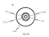
- the second lumen defined by the second catheter tube 42 has a diameter sufficient to accommodate a guide wire 180.
- the second catheter tube 42 may be made from a rigid material including, for example, nitinol, stainless steel or a rigid plastic material (see Fig. 10b ).
- the material of the distal end section of the second catheter tube 42 may have an increased flexibility compared to the material of the proximal end section in order to allow the distal end section of the catheter shaft 30 to pass the aortic arch during insertion of the catheter tip 10.
- the guiding tube 52 may be a 17F-catheter tube and the first catheter tube 32 may be a 12F-catheter tube.
- the distal end section of the second catheter tube 42 terminates in a soft catheter end tip 25 having an atraumatic shape.
- the soft catheter end tip 25 is provided with a channel aligned with the second lumen defined by the second catheter tube 42 such that a guide wire 180 accommodated within the second lumen of the second catheter tube 42 may pass through the channel of the soft catheter end tip 25.
- the second sleeve-shaped member 21 of the catheter tip 10 is connected to the soft catheter end tip 25 such that the opened end of the second sleeve-shaped member 21 faces in the proximal direction opposite to the direction of the soft catheter end tip 25 and to the second catheter tube 42.
- the stent holder tube 62 is made of a rigid material, for example, a rigid plastic material, stainless steel or nitinol.
- the distal end of the stent holder tube 62 terminates in the stent holder 15 which is also made of a rigid material, for example, a rigid plastic material or stainless steel.
- the passageway defined by the stent holder tube 62 is aligned with a channel which passes through the stent holder 15. In this way, the second catheter tube 42 is accommodated in the passageway of the stent holder tube 62 and the channel of the stent holder 15 such as to be moveable relative to the stent holder tube 62 and the stent holder 15.
- the first catheter tube 32 is made of a bendable but inelastic material.
- the first catheter tube 32 may be at least partly made of a braided or non-braided catheter tube.
- the first catheter tube 32 shall be adapted to transfer compression and tension forces from the first operating means 71 of the handle 70 to the first sleeve-shaped member 11 of the catheter tip 10 without overly changing its total length.
- the distal end of the first catheter tube 32 terminates at a flared section as a transition to the section defining the first sleeve-shaped member 11 of the catheter tip 10.
- the flared section and the first sleeve-shaped member 11 may be formed integrally and may be connected to the distal end section of the first catheter tube 31.
- the flared section may constitute the first sleeve-shaped member 11 of the catheter tip 10.
- the first sleeve-shaped member 11 and the flared section of the first catheter tube 31 may be all of the same material and originating from the same raw tube prior to a widening process so that the flared section and the first sleeve-shaped member 11 are the same elements.
- the insertion system 100 further comprises a guiding tube 52 having a cross-section greater than the cross-section of the first catheter tube 32.
- the guiding tube 52 defines a passageway and is disposed concentrically and coaxially with the first catheter tube 32, the stent holder tube 62 and the second catheter tube 42 such that the first catheter tube 32 with the stent holder tube 62 and the second catheter tube 42 accommodated therein is at least partly accommodated within the passageway defined by the guiding tube 52, wherein the first catheter tube 32 is moveable relative to the guiding tube 52.
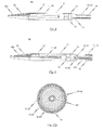
- the guiding tube 52 terminates proximal to the catheter tip 10 wherein the cross-section of proximal end section of the guiding tube 52 shall be the same as or less than the cross-section of the flared section provided at the proximal end of the first catheter tube 32 so that a smooth transition from the first sleeve-shaped member 11 of the catheter tip 10 to the guiding tube 52 may be achieved (see Fig. 9 ).
- the proximal end section of the guiding tube 52 terminates distal to the handle 70.
- the proximal end section of the guiding tube 52 may be detached / disconnected from the handle 70 so that the handle 70 as well as the first and second catheter tubes 32, 42 and the stent holder tube 62 together with catheter tip 10 may be moved relative to the guiding tube 52.
- the distal end of the guiding tube 52 is formed such that the flared section provided at the distal end section of the first catheter tube 32 may abut on the distal end of the guiding tube 52 without abrupt transition.
- the guiding tube 52 may be of a thin material such as to allow length deformation of the guiding tube 52 upon transfer of compression and tension forces.
- the material of the guiding tube 52 shall have sufficient stiffness in order to mechanically avoid kinking of the flexible sections of the distal portion of the catheter shaft 30 during insertion of the catheter tip 10.
- the proximal end of the guiding tube 52 is releasably connectable to the body 70' of the handle 70.
- the guiding tube 52 may have a double-function:
- the guiding tube 52 serves as a distal extension of the body 70' of the handle 70 relative to which the first and second operating means 71, 81 are moveable for manipulating the first and second sleeve-shaped members 11, 21 of the catheter tip 10.
- the position of the stent holder 15 relative to the native heart valve of the patient may be changed by moving the guiding tube 52 connected to the handle 70.
- the guiding tube 52 may serve as an introducer tube, i.e. as a portal for passing the catheter tip 10 of the catheter system 1 into the patient's body and up to the heart.
- an inlet port 53 may be provided at a proximal end section of the guiding tube 52 for injection of fluids into the guiding tube 52.
- a check valve may be provided at the proximal end section of the guiding tube 52 to prevent fluid from leaking out of the guiding tube 52.
- the catheter tip 10 of the insertion system 100 is advanced, for example, via the aorta to the implantation site.
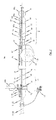
- Fig. 1 shows a part-sectioned representation of an exemplary embodiment of an insertion system 100 designed for transfemoral or transarterial access.
- an insertion system 100 may comprise a catheter system 1 and a handle 70 connected to the proximal end section of the catheter system 1.
- the catheter system 1 comprises a catheter tip 10 and a catheter shaft 30 for connecting the catheter tip 10 to the handle 70.
- the catheter tip 10 has a seat portion for accommodating a stent (see Figs. 12a-c ) in its collapsed state as well as a stent holder 15 for releasably fixing the stent.
- the seat portion of the catheter tip 10 is constituted by a first sleeve-shaped member 11 and a second sleeve-shaped member 21.
- the sleeve-shaped members 11, 21 of the catheter tip 10 are movable relative to each other and relative to the stent holder 15.
- the catheter shaft 30 comprises first force transmitting means 31, second force transmitting means 41 and guiding means 51.
- the first and second force transmitting means 41 31, 41 of the catheter system 1 are realized as flexible, elongated catheter tubes 32, 42.
- Each of the first and second catheter tubes 32, 42 defines a separate lumen.
- the guiding means 51 is realized as guiding tube 52 defining a passageway within which the first and second catheter tubes 32, 42 are received such as to be movable relative to the guiding tube 52.
- the guiding tube 52 has a distal end which terminates proximal to the catheter tip 10.
- the first catheter tube 32 has a length which is the same as, or substantially similar to the length of the second catheter tube 42.
- the first catheter tube 32 terminates at its distal end in a flared section as a transition to the section with wider cross-section defining the first sleeve-shaped member 11 of the catheter tip 10.
- the wider section of the first catheter tube 32 is formed integrally with the distal end section of the first catheter tube 32.
- the wider section has a length greater than the length of a collapsed stent to be accommodated in the catheter tip 10.
- the first force transmitting means 31 of the catheter system 1 is constituted by a first catheter tube 32 defining a first lumen
- the second force transmitting means 41 is constituted by a second catheter tube 42 defining a second lumen.
- the second catheter tube 42 has a cross-section less than the cross-section of the first catheter tube 32, wherein the first catheter tube 32 is disposed concentrically and coaxially with the second catheter tube 42.
- the cross-section of the catheter tip 10 is greater than or equal to the cross-section of the guiding tube 52.
- the guiding tube 52 has a cross-section which is greater than the cross-section of the part of the first catheter tube 32 which is received within the guiding tube 52.
- the cross-section of the catheter tip 10 is greater than the cross-section of the guiding tube 52.
- a check valve may be provided for preventing fluid from leaking out of the guiding tube 52.
- an inlet port 53 may be provided at the proximal end section of the guiding tube 52 for injection of fluids into the guiding tube 52.
- fluids such as saline solution may be injected through the inlet port 52 to flush the interior passageway of the guiding tube 52 and to reduce the incidence of blood clotting.
- a stopcock may be attached to the inlet port 53 to maintain the port 53 in a closed position when the port 53 is not being accessed to flush the passageway of the guiding tube 52.
- the guiding tube 52 is movable relative to the handle 70 and the first and second catheter tubes 32, 42. This provides a grip for the user who can hold the catheter shaft 30 at its proximal end section during positioning of the catheter tip 10 and during manipulation of the sleeve-shaped element 11 of the catheter tip 10.
- the user can hold the guiding tube 52, and in particular the proximal end section of the guiding tube 52 for supporting the movement of the first sleeve-shaped element 11 of the catheter tip 10 relative to the handle 70 such that the outer sheath of the catheter system 1 need not be held by the user or kinked.
- a handle 70 is utilized, said handle 70 comprising first and a second operating means 71, 81, which are connected by means of corresponding first and second force transmission means 31, 41 of the catheter shaft 30 to the first and second sleeve-shaped member 21s 11, 21 of the catheter tip 10.
- the first operating means 71 has a first pusher 73 which is functionally connected to the first slide 74.
- the first slide 74 is guided in a first guide 72 in the longitudinal direction L of the handle 70.
- the distal-side end of the first guide 72 defines the first stop 75 and the proximal-side end of the first guide 72 the second stop 76, which define the overall longitudinal displacement that can be effected with the first operating means 71.
- a locking element 77' may be positioned between the distal-side and the proximal-side end of the first guide 72, which defines the additional stop 77.
- the second operating means 81 of the handle 70 shown in Fig. 1 has a second pusher 83, which is functionally connected to a second slide 84.
- the second slide 84 is guided in a longitudinal guide (second guide 82) between a first stop 85 and a second stop 86.
- the second slide 84 is connected by means of the second force transmission means 41 with the second sleeve-shaped member 21 of the catheter tip 10.
- the second slide 84 is moved in the longitudinal direction L of the handle 70 from the first stop 85 to the second stop 86. This movement effects a longitudinal displacement of the second sleeve-shaped member 21 of the catheter tip 10 connected via the second force transmission means 41 with the second operating means 81.
- the second operating means 81 is equipped with a securing element 89, which may connect the second slide 84 with the body 70' of the handle 70 when in use.
- a longitudinal displacement of the second slide 84 to the second stop 86 is possible following removal or deactivation of the securing element 89.
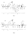
- Fig. 2 shows a further embodiment of a handle 70 of an insertion system 100 designed for transfemoral or transarterial access in a part-sectioned side view.
- the construction and mode of operation of the first and second operating means 81 71, 81 of the embodiment of the handle 70 shown in Fig. 2 is comparable in structural and functional respects to the handle 70 as previously described with reference to Fig.1 .
- elements in Fig. 2 that are generally similar to previously described elements have the same reference numbers compared with the reference numbers in Fig. 1 previously used for the similar elements.
- the handle 70 in accordance with Fig. 2 is provided with a third operating means 96 in the form of a wheel, by means of which a flexural link region 34 of the catheter shaft 30 can be controlled.
- a flexural link region 34 of the catheter shaft 30 can be controlled.
- the catheter shaft 30 is only optionally provided with such flexural link region 34. Rather, the material of the distal end section of the catheter shaft 30 may have an increased flexibility compared to the material of the proximal end section in order to allow the distal end section of the catheter shaft to pass 30 the aortic arch during insertion of the catheter tip.
- the third operating element 96 preferably has a detent device 100, to allow a set deflection of the flexural link region 34 of the catheter shaft 30 to be fixed.
- a suitable catch mechanism on the hand wheel of the third operating means 96, which cooperates with the body 70' of the handle 70.
- the flexural link region 34 of the catheter shaft 30 to be connected to the third operating means 96 by way of a control wire 35 whereby, on an actuation of the third operating means 96 via the control wire 35 a tensile forces is exerted on the flexural link region 34, which produces the deflection of the flexural link region 34 (see Fig. 3b ).
- the third operating means 96 for deflecting a flexural link region 34 of the catheter shaft 30 in case the catheter shaft 30 is provided with such a flexural link region 34.
- the handle 70 of the insertion system 100 designed for transarterial or transfemoral access may be provided with a pretensioning device, shown in Fig. 2 .
- a pretensioning device With such a pretensioning device, a constant tensile force may be exerted via the second operating means 81 on the second sleeve-shaped member 21 of the catheter tip 10.
- the pretensioning device may have a compression spring 97, permanently stressed along its spring axis, which is prestressed between a first stop 97a connected to the body 70' of the handle 70 and a second stop 97b connected to the proximal end region of the second operating means 81.
- a permanent, previously defined or definable tensile force is exerted on the second sleeve-shaped member 21 of the catheter tip 10.
- the pretensioning device implemented with the spring 97 in the embodiment in accordance with Fig. 2 may be advantageous when the catheter shaft 30 is bent during the implantation procedure, for example, when the catheter tip 10 of the insertion system 100 is inserted through the aorta.
- the outer fibres of the catheter shaft 30 are shortened. This can be compensated appropriately with the aid of the pretensioning device.
- the outer fibres of the catheter shaft 30 radially spaced from the neutral fibres are shortened.
- the second force transmission means 41 which connects the second operating means 81 with the second sleeve-shaped member 21 in the insertion system 100, normally runs along the neutral fibre of the catheter shaft 30, a bending contraction inevitably occurs when the catheter shaft 30 is bent, having the result that, despite fixing of the first operating means 71, the first sleeve-shaped member 11 of the catheter tip 10 is displaced relative to the stent holder 15 in a proximal direction.
- FIG. 3a , b A further exemplary embodiment of an insertion system 100 designed for transarterial / transfemoral access is shown in Figs. 3a , b.
- Elements in Figs. 3a , b that are generally similar to previously described elements have the same reference numbers compared with the reference numbers in Figs. 1 and 2 previously used for the similar elements.
- the insertion system 100 shown in Figs. 3a, b comprises a catheter system 1 of the kind as previously described with reference to Fig. 1 , i.e. a catheter system 1 having a catheter tip 10 and a catheter shaft 30 which is provided with a first catheter tube 32 acting as first force transmitting means 31, a second catheter tube 42 acting as second force transmitting means 41, and a guiding tube 52 acting as guiding means 51.
- the catheter shaft 30 utilized in the exemplary embodiment of the insertion system 100 depicted in Fig. 1 the catheter shaft 30 of the insertion system 100 shown in Figs. 3a, b is provided with a flexural link region 34 of the kind as previously described with reference to Fig. 2 .
- the insertion system 100 shown in Figs. 3a , b is provided with a different embodiment of a handle 70 which is used in order to manipulate the first and second sleeve-shaped members 11, 21 of the catheter tip 10.
- the end region of the handle 70 is in the form of a turning mechanism 98 (rotatable means), with which the second force transmission means 41 of the catheter shaft 30 can be twisted with the distal-side end tip 25 and the second sleeve-shaped member 21 of the catheter tip 10 fastened to it about the longitudinal axis L of the catheter tip 10.
- the second sleeve-shaped member 21 of the catheter tip 10 is connected by means of a loose bearing to the stent holder 15, allowing transmission of a turning moment between the second sleeve-shaped member 21 and the stent holder 15, without allowing transmission of any tensile or compression forces acting in the direction of the longitudinal axis L of the catheter tip 10.
- the stent holder 15 also turns correspondingly about the longitudinal axis L.
- the turning mechanism 98 preferably allows the stent holder 15 to twist through approximately 120°.
- the rotation of a stent housed in the catheter tip 10, and particularly the positioning hoops already released in the second functional state of the insertion system 100 can be controlled, facilitating precise positioning of the already expanded positioning hoops of the stent in the pockets of the insufficient, native heart valve.
- the rotation movement of the stent holder 15 about the longitudinal axis L of the catheter tip 10 that can be effected with the turning mechanism 98 exhibits a previously definable, preferably small delay in reaction to a turning moment initiated by means of the turning mechanism 98.
- the embodiment of the handle 70 shown in Fig. 3a is equipped with a third operating means 96 in the form of a wheel, with which a flexural link 34, preferably provided at the distal end region of the catheter shaft 30, can be deflected.
- a device for force transmission (control wire 35 - see Fig. 8 ) which is connected on one side to the flexural link regions 34 preferably provided at the distal end region of the catheter shaft 30 and, on the other side, to the third operating means 96 of the handle 70 implemented in the embodiment shown in Fig. 3 as a hand wheel.
- the device for force transmission as a control wire 35, which is passed through the inside of the first transmission means 31 and preferably at the distal end of the flexural link region 34 or at the proximal end of the catheter tip 10 (see Fig. 8 ) to have a directed effect on the curvature of the flexural link region 34.
- a control wire 35 which is passed through the inside of the first transmission means 31 and preferably at the distal end of the flexural link region 34 or at the proximal end of the catheter tip 10 (see Fig. 8 ) to have a directed effect on the curvature of the flexural link region 34.
- With the tensile forces that can be exerted on the flexural link region 34 with the aid of the control wire 35 it is possible to obtain a defined curvature of the distal end region of the catheter shaft 30. This is a particular advantage during transarterial / transfemoral access when navigating the aortic arch.
- FIG. 4 and 5 Further exemplary embodiments of an insertion system 100 which is suitable for transarterial / transfemoral access to the implantation location are shown in Figs. 4 and 5 .
- Elements in Figs. 4 and 5 that are generally similar to previously described elements have the same reference numbers compared with the reference numbers in Figs. 1 , 2 and 3a, b previously used for the similar elements.
- Figs. 4 and 5 differ first and foremost in relation to the implementation of the corresponding operating means 71, 81 of the handle 70.
- the insertion system 100 in accordance with Fig. 4 has a handle 70 with which the first operating means 71, which is used for manipulation of the first sleeve-shaped member 11 of the catheter tip 10, is similar to a trigger of a revolver.
- the user such as a physician who carries out the treatment may hold the handle 70 at the grip 88, while the first operating means 71 in the form of a trigger of a revolver is operated with the index finger of the hand holding it.
- a handle 70 is used which corresponds in structural and functional respects to the handle 70 used with the insertion system 100 in Fig. 3 with the exception of the grip 88 provided in the embodiment in accordance with Fig. 3 .
- FIG. 6a-d A description is given in the following, with reference to Figs. 6a-d and Figs. 7a-d , of the functional coaction of the components of an insertion system 100, which is suitable for a transarterial or transfemoral access to the implantation location.
- Elements in Figs. 6a to 6d and Figs. 7a to 7d that are generally similar to previously described elements have the same reference numbers compared with the reference numbers in Figs. 1 to 5 previously used for the similar elements.
- FIGs. 6a to 6d for illustrating the procedure for loading a stent into the catheter tip 10 of the insertion system 100.
- Figs. 7a to 7d the stepwise release of a stent mounted in the catheter tip 10 of the insertion system 100 is illustrated.
- the handle 70 for the transarterial / transfemoral insertion system 100 has a wheel rotatably mounted in the handle 70 which is functionally connected to the first sleeve-shaped member 11 of the catheter tip 10 associated with the first operating means 71 via a corresponding first force transmission means 31, so that force can be directly transmitted from the first operating means 71 in the form of the wheel to the first sleeve-shaped member 11 of the catheter tip 10.
- the first operating means 71 of the handle 70 in accordance with Fig. 6 and Fig. 7 can turn between a first stop and a second stop, in order to execute a definable longitudinal displacement stroke on the first sleeve-shaped member 11 of the catheter tip 10.
- the first operating means 71 of the handle 70 is provided with a additional stop between the first and second stop which cooperates, on one side with the first stop and on the other up with the second stop so that, on actuation of the first operating means 71, a longitudinal displacement of the first sleeve-shaped member 11 of the catheter tip 10 can be effected relative to the stent holder 15 of the catheter tip 10, consisting of two defined separate steps.
- the additional stop associated with the first operating means 71 is in the form of a locking element 77' positioned removably in the flow of force between the wheel and the first sleeve-shaped member 11 of the catheter tip 10, interrupting direct force transmission from the wheel to the first sleeve-shaped member 11 of the catheter tip 10.
- the additional stop associated with the first operating means 71 it is possible for the additional stop associated with the first operating means 71 to be in the form of a locking element restricting the free rotation of the wheel between the first and the second stop.
- the first operating means 71 of the handle 70 used with the insertion system 100 designed for transarterial / transfemoral access not to be a wheel, but to be implemented as a pusher mechanism.
- the second operating means 81 has a second slide 84 guided in a second guide 82 and functionally connected to a second pusher 83.
- This second slide 84 which is guided in the interior of the handle 70 and therefore cannot be seen in the view of Figs. 6 and 7 , is functionally connected to the second sleeve-shaped member 21 of the catheter tip 10 associated with the second operating means 81 by means of a second force transmission means 41 so that, on actuation of the second operating means 81, force is directly transmitted from the second slide 84 to the second sleeve-shaped member 21 of the catheter tip 10.
- the second operating means 81 can be displaced between a first position (Pos. 1) and a second position (Pos. 2) in the longitudinal direction of the handle 70, whereby the longitudinal displacement stroke that can be thus effected via the second force transmission means 41 is transferred directly to the second sleeve-shaped member 21 of the catheter tip 10.
- the first and second positions are each defined with the aid of a first and a second stop 85, 86.
- a securing element 89 is provided, associated with the second operating means 81, which is removably located on the second guide 82 and which blocks longitudinal displacement of the (second) slide 84 associated with the second operating means 81 when used.
- the handle 70 which is used with the transarterial / transfemoral insertion system 100 of the embodiment shown in Figs. 6 and 7 further exhibits an optional grip 88, which facilitates the operability of the handle 70 and in particular the operating conformity of the handle 70.
- the grip 88 is preferably releasably connected to the body 70' of the handle 70 and can optionally be fixed at different positions on the body 70' of the handle 70.
- the catheter tip 10 In relation to the construction of the catheter tip 10 which is used, for example, with the insertion system 100 shown in Figs. 6 and 7 and which allows transarterial / transfemoral access of a stent housed in the catheter tip 10 to the implantation location, it can be seen from Figs. 6 and 7 that the catheter tip 10 has a stent holder 15 for releasably fixing of, for example, the second retaining region of a stent that can be housed in the catheter tip 10.
- the retaining elements 16 of the stent holder 15 in the form of a crown are provided at the proximal end of the stent holder 15.
- the catheter tip 10 of the insertion system 100 designed for transarterial / transfemoral access comprises a mounting device for mounting a heart valve stent, where required, with a heart valve prosthesis fastened to it.
- the mounting device of the catheter tip 10 consists of a first sleeve-shaped member 11, particularly for accommodating the positioning hoops of a stent, and a second sleeve-shaped member 21, in particular for accommodating the heart valve prosthesis fastened to it, when required.
- the first operating means 71 of the handle 70 co-operates in the embodiment according to Figs. 6 and 7 with the first sleeve-shaped member 11 of the catheter tip 10 so that, on actuation of the first operating means 71, by transfer of a defined longitudinal displacement stroke, a previously definable longitudinal displacement of the first sleeve-shaped member 11 can be effected relative to the stent holder 15.
- the insertion system 100 according to Figs.
- the second operating means 81 of the handle 70 co-operates with the second sleeve-shaped member 21 of the catheter tip 10 so that, on actuation of the second operating means 81, by transfer of a defined longitudinal displacement stroke, a previously definable longitudinal displacement of the second sleeve-shaped member 21 of the catheter tip 10 relative to the stent holder 15 can be effected.
- the second sleeve-shaped member 21, which is used to house the retaining hoops of the stent with, where required, the heart valve prosthesis fastened to them, is located at the distal end region of the catheter tip 10, while the first sleeve-shaped member 11 is located between the second sleeve-shaped member 21 and the handle 70.
- the second force transmission means 41 which connects the second operating means 81 of the handle 70 to the second sleeve-shaped member 21 of the catheter tip 10, is preferably in the form of an inner catheter running inside the interior of the catheter or tube system.
- the second sleeve-shaped member 21 On actuation on the second operating means 81, the second sleeve-shaped member 21 can be moved relative to the stent holder 15 in the longitudinal direction L of the catheter tip 10 in a distal direction, thus away from the handle 70, while, on actuation of the first operating means 71 of the handle 70, the first sleeve-shaped member 11 of the catheter tip 10 can be moved relative to the stent holder 15 in the longitudinal direction L of the catheter tip 10 in a proximal direction, and thus towards the handle 70.
- FIG. 7a An embodiment of a transarterial / transfemoral insertion system 100 is shown in its four different functional states in Figs. 7a to 7d .
- the insertion system 100 is shown in its first functional state in Fig. 7a , in which the catheter shaft 30 with the catheter tip 10 and, where required, with the stent accommodated in it can be inserted into the patient transarterially or transfemorally and advanced via the aorta to the implantation site.
- the catheter tip 10 is completely closed, whereby the two sleeve-shaped members 11, 21 of the catheter tip 10 overlap telescopically.
- the respective diameters of the sleeve-shaped members 11, 21 are chosen so that the folded-up retaining hoops of a stent, with the heart valve prosthesis fastened to them where required, can be housed in the second sleeve-shaped member 21.
- the folded-up positioning hoops of the stent housed between the second sleeve-shaped member 21 and the first sleeve-shaped member 11 are held together in their folded form.
- the second retaining region of the stent is shown in the first functional state of the insertion system 100, as shown in Fig. 7a , with the stent holder 15 fixed at the proximal end of the catheter tip 10.
- the retaining elements (retaining rings etc.) provided at the second retaining region of the stent are engaged with retaining elements 16 of the stent holder 15.
- the retaining elements 16 of the stent holder 15 are covered by the first sleeve-shaped member 11 of the catheter tip 10 in the first functional state shown in Fig. 7a , so that an engagement between retaining elements provided on the second retaining region of a stent and retaining elements 16 of the stent holder 15 would be possible.
- the first functional state of the insertion system 100 shown in Fig. 7a is maintained during the transarterial insertion procedure.
- the insertion system 100 is transferred from the first functional state shown in Fig. 7a to the second functional state shown in Fig. 7b , by transferring the first operating means 71 (shown in the embodiment of the wheel in Fig. 7 ) from the first position into the second position.
- the longitudinal displacement stroke transferred by actuation of the first operating means 71 to the first sleeve-shaped member 11 of the catheter tip 10 effects a displacement of the first sleeve-shaped member 11 relative to the stent holder 15 in the proximal direction, thus towards the handle 70.
- the longitudinal displacement stroke executed on the first sleeve-shaped member 11 of the catheter tip 10 during the transition from the first functional state (see Fig. 7a ) to the second functional state (see Fig. 7b ) by the first operating means 71 of the handle 70 via a corresponding first force transmission means 31 is previously defined so that the first sleeve-shaped member 11 is displaced relative to the stent holder 15 in the proximal direction just so far that the positioning hoops of a stent housed in the catheter tip 10 would be released, though the distal end of the first sleeve-shaped member 11 of the catheter tip 10 would still cover the retaining elements 16 of the stent holder 15, so that the engagement between the retaining elements provided at the second retaining region of the stent and the retaining elements 16 of the stent holder 15 would be secure.
- the first retaining region of a stent housed in the catheter tip 10 with the heart valve prosthesis fastened to it would continue to be housed in its folded together state in the sleeve-shaped element of the second sleeve-shaped member 21.
- the positioning hoops of a stent housed in the catheter tip 10 released in the second functional state of the insertion system 100 are opened as a result of the radial forces acting on them and can thus be positioned in the pockets of the insufficient native heart valve.
- the insertion system 100 is transferred from the second functional state shown in Fig. 7b into the third functional state shown in Fig. 7c . This is done my manipulation of the second operating means 81, after the securing element 89 associated with the second operating means 81 has been removed.
- the second sleeve-shaped member 21 of the catheter tip 10 associated with the second operating means 81 is moved relative to the stent holder 15 by a previously established longitudinal displacement stroke defined with the second operating means 81 in a distal direction, thus away from the handle 70.
- the longitudinal displacement stroke acting on the second sleeve-shaped member 21 is chosen so that the sleeve-shaped member 21 no longer covers the first retaining region of a stent housed in the catheter tip 10 with the heart valve prosthesis fastened to it, where required, and thus releases the first retaining region of the stent. Due to the action of the radial forces, the distal retaining region of the stent with the heart valve prosthesis attached to it, where required, unfolds completely.
- the distal end region of the first sleeve-shaped member 11 continues to cover the retaining elements 16 of the stent holder 15, so that the engagement between the retaining elements of a stent housed in the catheter tip 10 and the retaining elements 16 of the stent holder 15 is secure and the proximal retaining region of the stent is in its folded-up state.
- This anchorage of the stent to the catheter tip 10 of the insertion system 100 allows an explantation of a stent that is already partially unfolded by returning the insertion system 100 from the third functional state, by appropriate manipulation of the second operating means 81 of the handle 70, to the second functional state and then by suitable actuation of the first operating means 71 transfer to the first functional state.
- the insertion system 100 is transferred from the third functional state shown in Fig. 7c into the fourth functional state shown in Fig. 7d , by turning the first operating means 71 of the handle 70 further from the second position to the third position after removal of the securing element 79 (locking element).
- This manipulation of the first operating means 71 that can be effected after removal of the securing element 79 results in a further defined movement of the first sleeve-shaped member 11 relative to the stent holder 15 of the catheter tip 10 in a proximal direction, thus towards the handle 70.
- the longitudinal displacement stroke executed on the first sleeve-shaped member 11 is chosen so that the distal end of the first sleeve-shaped member 11 no longer covers the retaining elements 16 of the stent holder 15, as a result of which an engagement between the retaining elements of a stent housed in the catheter tip 10 and the retaining elements 16 of the stent holder 15 can be released, which would also lead to a complete release of the second retaining region of the stent and a complete separation of the stent from the catheter tip 10 and correspondingly to a complete unfolding of the stent.
- FIG. 6a The four functional states of the insertion system 100 designed for transarterial / transfemoral access, previously described with reference to Figs. 7a to 7d , are shown in reverse order in Figs. 6a to 6d to clarify the procedure for loading a stent into the catheter tip 10 of the insertion system 100.
- Comparison between Figs. 6a to 6d and Figs. 7a to 7d show that the insertion system 100 can be loaded with a heart valve stent by transferring the insertion system 100, starting from its fourth functional state in accordance with Fig. 6a (see Fig. 7d ), into its third functional state in accordance with Fig. 6b (see Fig.
- FIG. 9 for describing an exemplary embodiment of the catheter tip 10. Elements in Fig. 9 that are generally similar to previously described elements have the same reference numbers compared with the reference numbers in Figs. 1 to 7 previously used for the similar elements.
- catheter shaft 30 An exemplary embodiment of a catheter shaft 30 is described in the following, with reference to the illustration in Fig. 9 .
- This catheter shaft 30 can be used with an insertion system 100 designed for transarterial or transfemoral access.
- Fig. 9 shows an exemplary embodiment of a shaft for an insertion system 100 in a cross-sectional elevation.
- the catheter shaft 30 exhibits a first force transmission means 31 in the form of a first catheter tube 32, whereby this first catheter tube 32 is used to connect the first operating means 71 of the handle 70 to the first sleeve-shaped member 11 of the catheter tip 10.
- the first force transmission means 31 implemented as a first catheter tube 32 may be clamped between a screw cap 74' and the first slide 74 of the first operating means 71 and consequently is permanently connected to the first slide 74.
- the distal-side end region of the first catheter tube 32 merges into the first sleeve-shaped member 11 of the catheter tip 10 in the form of the stent sheath.
- the second force transmission means 41 of the catheter shaft 30 used with an insertion system 100 designed for transarterial or transfemoral access is preferably implemented as a second catheter tube 42.
- the proximal-side end region of the second catheter tube 42 is connected to the second operating means 81 of the handle 70.
- the distal-side end region of the second catheter tube 42 is connected to the catheter end tip 25 of the catheter tip 10.
- the second sleeve-shaped member 21 of the catheter tip 10 is permanently connected by means of its distal-side end to the end tip 25 of the catheter tip 10 so that, on actuation of the second operating means 81 via the force transmission means 41 in the form of the second catheter tube 42, a tensile or compressive force can be transmitted to the second sleeve-shaped member 21 of the catheter tip 10.
- the exemplary embodiment of the catheter tip 10 further comprises a stent holder 15 at the proximal end section of the catheter tip 10.
- the stent holder 15 has a passageway extending there through.
- the distal end section of the second force transmitting means 41 (second catheter tube 42) passes through the passageway of the stent holder 15 and terminates at the second sleeve-shaped member 21.
- the respective sleeve-shaped members 11, 21 of the catheter tip 10 can be manipulated by corresponding operating means 71, 81 of a handle 70 (not shown in Fig. 9 ).
- the first sleeve-shaped member 11 of the catheter tip 10 is connected with a first operating means 71 of a handle 70 by using a first force transmitting means 31.
- the second sleeve-shaped member 21 of the catheter tip 10 is connected to a second operating means 81 of the handle 70 by using a second force transmitting means 41.
- the first force transmitting means 31 is constituted by a first catheter tube 32 defining a first lumen
- the second force transmitting means 41 is constituted by a second catheter tube 42 defining a second lumen.
- the second catheter tube 42 has a cross-section less than the cross-section of the first catheter tube 32, wherein the first catheter tube 32 is disposed concentrically and coaxially with the second catheter tube 42.
- the distal end section of the second catheter tube 42 passes through the opened front face of the second sleeve-shaped member 21 and terminates in a cone-shaped end tip 25 of the catheter system 1, wherein the base of this cone-shaped end tip 25 defines the distal front face of the second sleeve-shaped member 21.
- the end tip 25 of the catheter system 1 is preferably a soft catheter end tip, for example a soft polymeric catheter end tip.
- the first catheter tube 32 terminates after an intermediate flared section in a section with wider cross-section defining the first sleeve-shaped member 11 of the catheter tip 10.
- the flared section is formed integrally with the distal end section of the first catheter tube 32.
- the flared section has a length greater than the length of a collapsed stent to be accommodated in the catheter tip 10, wherein the difference in the length between the flared section and the stent in its collapsed state represents the length of the stent holder 15.
- the distal end of the guiding tube 52 terminates proximal to the catheter tip 10.
- the guiding tube 52 defines a passageway within which the first and second catheter tube 42 32, 42 are received such as to be movable relative to the guiding tube 52.
- the distal end of the guiding tube 52 may be tapered such that it abuts the first catheter tube 32 in one of its possible positions on the catheter shaft 30.
- Fig. 10a is a cross-sectional view of a catheter shaft 30 according to an exemplary embodiment.
- the second force transmission means 41 in the form of the second catheter tube 42 runs along the neutral fibre of the catheter shaft 30 inside the first catheter tube 32.
- the space between the first catheter tube 32 and the second catheter tube 42 may be filled with a filler material, so that a filler body 40 is formed.
- the filler material is preferably a relatively elastic plastic material to allow the catheter shaft 30 to bend overall.
- the filler body 40 is used for connecting the stent holder 15 of the catheter tip 10 to the body 70' of the handle 70.
- a stent holder tube 62 may be used for connecting the stent holder 15 of the catheter tip 10 to the body 70' of the handle 70.
- the stent holder tube 62 may have a distal end connected to the stent holder 15, a proximal end connected to the body 70' of the handle 70 and a passageway extending through the stent holder tube 62.
- the stent holder tube 62 has a cross-section less than the cross-section of the first catheter tube 32 and greater than the cross-section of the second catheter tube 42, wherein the first catheter tube 32 is disposed concentrically and coaxially with the stent holder tube 62 thereby accommodating the stent holder tube 62 such that the first catheter tube 32 is moveable relative to the stent holder tube 62.
- the passageway of the stent holder tube 62 shall have a diameter sufficient to accommodate the second catheter tube 42 such that the second catheter tube 42 is moveable relative to the stent holder tube 62.
- the filler body 40 (or the stent holder tube 62) may be connected by means of a fixing 87 to the body 70' of the handle 70.
- the proximal-side end region of the stent holder 15 attaches at the distal-side end region of the filler body 40 (see Fig. 8 ).
- the connection between the stent holder 15 and the filler body 40 is preferably chosen so that it allows rotation of the stent holder 15 relative to the filler body 40. This is especially necessary for control of the rotation of the positioning hoops of the already partially released stent during the implantation procedure (see Fig. 12a ).
- the complete catheter system 1 can be rotated for appropriate positioning of a stent connected with the catheter tip 10 and, in particular the positioning hoops of an already partially released stent during the implantation procedure. This is possible due to an appropriate transmission of torque and the flexibility of the catheter system 1.
- a stent holder tube 62 is used for connecting the stent holder 15 of the catheter tip 10 to the body 70' of the handle 70, the stent holder tube 62 may be rotatable relatively to the first and second catheter tubes 32, 42 about the longitudinal axis L of the catheter system 1. This will be described later in more detail with reference to the exemplary embodiment depicted in Fig. 10b .
- the second force transmission means 41 in the form of the second catheter tube 42 can be turned about the longitudinal direction L, for example, by means of a rotatable cap 98 which may be provided at the proximal end region of the handle 70. This rotary movement is transferred from the second catheter tube 42 direct to the end tip 25 of the catheter tip 10 and thus to the second sleeve-shaped member 21 of the catheter tip 10.
- the second catheter tube 42 runs through the body of the stent holder 15 and cooperates with the stent holder 15 with the aid of a suitable toothing, to transmit a turning moment exerted by means of the rotary cap of the handle 70 on the second catheter tube 42 to the stent holder 15, while tensile or compression forces acting in the longitudinal direction L of the catheter tip 10 are not transmitted from the second catheter tube 42 to the stent holder 15.
- a least one fluid channel 43 may be provided in the filler body 40 of the catheter shaft 30, connected at its proximal-side end to an injection adapter 99b (see Fig. 2 ) and at its distal-side end correspondingly to the catheter tip 10, consequently ensuring supply of fluid to the catheter tip 10 and draining of fluid from the catheter tip 10.
- a channel may be provided in the filler body 40 for accommodating a control wire (control wire 35 - see Fig. 8 ), with an operating means may cooperate with a flexural link region, in case the catheter shaft 30 is provided with such a flexural link region (see Fig. 3 and Fig. 2 ).
- a control wire control wire 35 - see Fig. 8
- an operating means may cooperate with a flexural link region, in case the catheter shaft 30 is provided with such a flexural link region (see Fig. 3 and Fig. 2 ).
- the distal-side end of a control wire 35 is fixed to the proximal-side end region of the stent holder 15.
- Fig. 10b is a cross-sectional view of a catheter shaft 30 according to an alternative exemplary embodiment.
- the first force transmitting means 31 may be constituted by a first catheter tube 32 defining a first lumen and the second force transmitting means 41 is constituted by a second catheter tube 42 defining a second lumen.
- the second catheter tube 42 may have a cross-section less than the cross-section of the first catheter tube 32.
- the first catheter tube 32 may be disposed concentrically and coaxially with the second catheter tube 42 and the second catheter tube 42 is received within the first lumen defined by the first catheter tube 32.
- a stent holder tube 62 is provided for connecting the stent holder 15 to the handle 70, said stent holder tube 62 having a distal end connected to the stent holder 15 and a proximal end connected to a body 70' of the handle 70.
- the stent holder tube 62 may have a cross-section less than the cross-section of the first catheter tube 32.
- the first catheter tube 32 may be disposed concentrically and coaxially with both, the second catheter tube 42 on the one hand and the stent holder tube 62 on the other hand.
- the stent holder tube 62 has a cross-section less than the cross-section of the first catheter tube 32 and greater than the cross-section of the second catheter tube 42 such that the stent holder tube 62 is received within the first lumen defined by the first catheter tube 32 and the second catheter tube 42 is received within a passageway defined by the stent holder tube 62.
- the passageway defined by the stent holder tube 62 has a diameter sufficient to accommodate the second catheter tube 42 such that the second catheter tube 42 is moveable relative to the stent holder tube 62.
- the second lumen defined by the second catheter tube 42 has a diameter sufficient to accommodate a guide wire 180.
- the second catheter tube 42 may be made from a rigid material including, for example, nitinol, stainless steel or a rigid plastic material.
- the material of the distal end section of the second catheter tube 42 may have an increased flexibility compared to the material of the proximal end section in order to allow the distal end section of the catheter shaft 30 to pass the aortic arch during insertion of the catheter tip 10.
- the guiding tube 52 may be a 17F-catheter tube and the first catheter tube 32 may be a 12F-catheter tube.
- the stent holder tube 62 is made of a rigid material, for example, a rigid plastic material, stainless steel or nitinol.
- the distal end of the stent holder tube 62 terminates in the stent holder 15 which is also made of a rigid material, for example, a rigid plastic material or stainless steel.
- the passageway defined by the stent holder tube 62 is aligned with a channel which passes through the stent holder 15. In this way, the second catheter tube 42 is accommodated in the passageway of the stent holder tube 62 and the channel of the stent holder 15 such as to be moveable relative to the stent holder tube 62 and the stent holder 15.
- the embodiments of the insertion system 100 designed for transarterial / transfemoral access may have a first injection adapter 99a at the proximal end of the handle 70.
- This first injection adapter 99a is used for flushing the insertion system 100 and as outlet of a guide wire 180, with the aid of which the actual introduction of the catheter shaft 30 with the catheter tip 10 provided at the distal end of the catheter shaft 30 into the body of the patient is simplified.
- the catheter shaft 30, the catheter tip 10 and the handle 70 are thereby threaded into the guide wire 180 and pushed along it, for example into the aorta and to the heart of the patient.
- a second injection adapter 99b may further be provided, by means of which a liquid coolant etc. can be passed, for example, via the fluid channels 43 (see Fig. 10a ) formed in the interior of the catheter shaft 30 to the catheter tip 10.
- a liquid coolant etc.
- a stent accommodated in the catheter tip 10 can be appropriately cooled while the catheter tip 10 is being advanced to the implantation location, as long as the insertion system 100 is in its first functional state, in which the catheter tip 10 is completely enclosed by the telescopically arranged sleeve-shaped members 11 and 21.
- the provision of cooling that can be produced with the second injection adapter 99b for the stent accommodated in the catheter tip 10 is a particular advantage when a shape memory material is used as stent material and when the stent can deform under the effect of an external stimulus from a temporary form to a permanent form, whereby the temporary form exists in the first configuration of the stent (in the folded-up state, when the stent is accommodated in the catheter tip 10) and the permanent form exists in the second configuration of the stent (in the expanded state of the stent after release of the stent from the catheter tip 10).
- the guiding tube 52 is preferably made from a material allowing the guiding tube 52 to be capable of traversing a tortuous pathway in the body of the patient without kinking.
- the guiding tube 52 may include an inner lubricious liner, an outer polymeric jacket, and a coil reinforcement between the inner and outer layers.
- first and second catheter tubes 32, 42 of the catheter shaft 30 are preferably made from flexible, sterilizable materials. These materials may include, for example, polyurethane, silicone, polyvinyl chloride (PVC) nylon and/or polyether block amide, e.g. Pebax ® .
- the first catheter tube 32 and/or second catheter tube 42 are/is at least partly made from a less rigid material than the guiding tube 52.
- the first catheter tube 32 and/or the second catheter tube 42 are/is at least partly made of a braided wire construction.
- the stent holder tube 62 may also be at least partly made of a braided wire construction.
- FIG. 12a to 12c A preferred embodiment of a medical device for treatment of a heart valve stenosis and/or heart valve insufficiency in a patient is described in the following with reference to Figs. 12a to 12c .
- the medical device exhibits an insertion system 100 designed for transarterial / transfemoral access, as has been described in detail previously, for example, with reference to Figs. 1 to 10 .
- the medical device has an expandable heart valve stent 150 mounted in the catheter tip 10 of the insertion system 100, to which a heart valve prosthesis 160 to be implanted is fastened.
- the stent 150 In the first functional state, not shown, the stent 150 exhibits a first, previously definable configuration, in which it is in its folded-together state.
- the stent 150 is designed to adopt a second previously definable configuration in the implanted state, in which it exists in its expanded state.
- the stent 150 is transferred sequentially, following a previously definable sequence of events in steps from its first previously defined configuration into its second previously defined configuration.
- the stent 150 that is used with the medical device in accordance with the depiction in Figs. 12a to 12c exhibits a first retaining region, to which the heart valve prosthesis 160 is attached. Further, the stent 150 comprises a second retaining region with three retaining elements 151, each in the configuration of retaining rings, which can be brought in to a releasable engagement with the retaining elements 16 of the stent holder 15 provided in the catheter tip 10.
- the stent 150 has three retaining hoops 153 to accommodate the heart valve prosthesis 160 and three positioning hoops 154 for automatic positioning of the stent 150 at the implantation site, whereby the respective positioning hoops 154 of the stent 150 are designed in functional and structural respects to engage the pockets 170 of the native heart valve during the implantation procedure and in the implanted state of the stent 150, in particular from the second functional state of the insertion system 100.
- each positioning hoop 154 and its associated retaining hoop 153 has an essentially U or V-shaped structure, which is closed towards the distal end of the stent 150.
- the stent 150 which together with the insertion system 100 forms the basis of the medical device, is especially suitable for insertion into the body of a patient with the aid of the insertion system 100 with minimal invasiveness.
- the distinctive feature of the stent 150 is that the three positioning hoops 154 of the stent 150 undertake the function of automatic positioning of the stent 150 with the heart valve prosthesis 160 attached to it in the aorta of the patient.
- the positioning hoops 154 have radiused head sections, which engage in the pockets 170 of the insufficient heart valve to be replaced by the heart valve prosthesis during positioning of the stent 150 at the implantation site.
- the provision of a total of three positioning hoops 154 takes care of the necessary positioning accuracy in the rotary direction.
- the catheter tip 10 and the catheter shaft 30 of the transarterial or transfemoral insertion system 100 has been inserted by a puncture of the groin artery of the patient and the catheter tip 10 has been advanced to the implantation site with the aid of a guide wire 180.
- the insertion system 100 to be used is shown already in its second functional state in Fig. 12a .
- the second functional state of the insertion system 100 designed for transarterial or transfemoral access has been described previously, for example with reference to Fig. 7b .
- the first sleeve-shaped member 11 of the catheter tip 10 has already moved by a first predetermined amount of movement in a proximal direction, and thus towards the handle 70, leading to a release of the positioning hoops 154 of the stent 150.
- These already expanded positioning hoops 154 of the stent 150 shown in Fig. 12a are positioned - where necessary by a suitable rotation of the stent holder 15 of the catheter tip 10 - in the pockets 170 of the native heart valve position.
- the insertion system 100 is transferred from its second functional state (see Fig. 7b ) into its third functional state (see Fig. 7c ).
- FIG. 12b shows the insertion system 100 in accordance with Fig. 12a , in which the second sleeve-shaped member 21 has been displaced in a distal direction so that the first retaining region of the stent 150 with the retaining hoops 153 and the heart valve prosthesis 160 attached to them are released.
- These components are opened as a result of the radial forces attacking them, whereby the old heart valves are clamped between the positioning hoops 154 and the retaining hoops 153.
- Fig. 12 shows the effect of the transfer of the insertion system 100 into its fourth functional state on the heart valve prosthesis 160 and the stent 150.
- the first sleeve-shaped member 11 of the catheter tip 10 has been displaced further in a proximal direction, as a result of which the anchorage of the retaining elements 151 on the second retaining region of the stent 150 is released. This has the result that that the second retaining region of the stent 150 can also expand and press against the vessel wall.
- the old (insufficient) heart valve is pressed against the vessel wall at the same time due to the self-expanding characteristic of the stent 150, as can be seen in particular in Fig. 12c .
- the semilunar heart valves of the insufficient, native heart valve are clamped between the positioning hoops 154 and the retaining hoops 153 because of the expansion of the stent 150, in addition to which the heart valve prosthesis 160 located on the first retaining region of the stent 150 is optimally positioned and is stably anchored.
- the disclosed solutions provide an improved insertion system 100 with the stent mountable in the catheter tip 10 of the insertion system 100.
- the stent may be inserted transarterially by the special insertion system 100 and can be optimally positioned, so that a heart valve prosthesis sewn on the first retaining region of the stent can undertake the function of the insufficient or stenosed native heart valve.
- the radial forces developed due to the self-expanding characteristic of the stent ensure a secure anchoring in the area of the aorta.
- the catheter system 1 of the insertion system 100 is preferably an 18 to 21F introducer, which is compatible with 21F-insertion tubes and a 0.035" guide wire 180.
- the length of the catheter system 1 for transarterial access should be at least 100 cm.
- the optionally provided flexural link region at the distal region of the catheter system 1 is preferably approximately 30 cm.
- FIG. 13a A further embodiment of a catheter tip 10 for an insertion system for transfemoral / transarterial insertion of an expandable heart valve stent is shown in its four different functional states in Figs. 13a to 13d .
- the catheter tip 10 is shown in its first functional state in Fig. 13a , in which the catheter shaft with the catheter tip 10 and, where required, with the stent accommodated in it can be inserted into the patient transarterially or transfemorally and advanced via the aorta to the implantation site.
- the catheter tip 10 is completely closed, whereby the two sleeve-shaped members 11, 21 of the catheter tip 10 abut.
- the two sleeve-shaped members 11, 21 of the catheter tip 10 have an equal outer cross-section diameter, thereby not forming a step in the state depicted in Fig. 13a .
- the respective inner diameters of the sleeve-shaped members 11, 21 are chosen so that the folded-up retaining hoops of a stent, with the heart valve prosthesis fastened to them where required, can be housed in the second sleeve-shaped member 21.
- the folded-up positioning hoops of the stent housed between the second sleeve-shaped member 21 and the first sleeve-shaped member 11 are held together in their folded form.
- the second retaining region of the stent is fixed with the stent holder 15 at the proximal end of the catheter tip 10.
- the retaining elements (retaining rings etc.) provided at the second retaining region of the stent are engaged with retaining elements 16 of the stent holder 15.
- the retaining elements 16 of the stent holder 15 are covered by the first sleeve-shaped member 11 of the catheter tip 10 in the first functional state shown in Fig. 13a , so that an engagement between retaining elements provided on the second retaining region of a stent and retaining elements 16 of the stent holder 15 would be possible.
- the first functional state of the catheter tip 10 shown in Fig. 13a is maintained during the transarterial insertion procedure.
- the catheter tip 10 is transferred from the first functional state shown in Fig. 13a to the second functional state shown in Fig. 13b , by transferring the first operating means of the handle (first operating means 71 shown in the embodiment of the wheel in Fig. 7 ) from the first position into the second position.
- the longitudinal displacement stroke transferred by actuation of the first operating means 71 to the first sleeve-shaped member 11 of the catheter tip 10 effects a displacement of the first sleeve-shaped member 11 relative to the stent holder 15 in the proximal direction, thus towards the handle 70.
- the longitudinal displacement stroke executed on the first sleeve-shaped member 11 of the catheter tip 10 during the transition from the first functional state (see Fig. 13a ) to the second functional state (see Fig. 13b ) by the first operating means 71 of the handle 70 via a corresponding first force transmission means 31 is previously defined so that the first sleeve-shaped member 11 is displaced relative to the stent holder 15 in the proximal direction just so far that the positioning hoops of a stent housed in the catheter tip 10 would be released, though the distal end of the first sleeve-shaped member 11 of the catheter tip 10 would still cover the retaining elements 16 of the stent holder 15, so that the engagement between the retaining elements provided at the second retaining region of the stent and the retaining elements 16 of the stent holder 15 would be secure.
- the first retaining region of a stent housed in the catheter tip 10 with the heart valve prosthesis fastened to it would continue to be housed in its folded together state in the sleeve-shaped element of the second sleeve-shaped member 21.
- the positioning hoops of a stent housed in the catheter tip 10 released in the second functional state of the catheter tip 10 are opened as a result of the radial forces acting on them and can thus be positioned in the pockets of the insufficient native heart valve.
- the catheter tip 10 is transferred from the second functional state shown in Fig. 13b into the third functional state shown in Fig. 13c . This is done my manipulation of the second operating means 81 of the handle, after the securing element 89 associated with the second operating means 81 has been removed.
- the second sleeve-shaped member 21 of the catheter tip 10 associated with the second operating means 81 is moved relative to the stent holder 15 by a previously established longitudinal displacement stroke defined with the second operating means 81 in a distal direction, thus away from the handle 70.
- the longitudinal displacement stroke acting on the second sleeve-shaped member 21 is chosen so that the sleeve-shaped member 21 no longer covers the first retaining region of a stent housed in the catheter tip 10 with the heart valve prosthesis fastened to it, where required, and thus releases the first retaining region of the stent. Due to the action of the radial forces, the distal retaining region of the stent with the heart valve prosthesis attached to it, where required, unfolds completely.
- the distal end region of the first sleeve-shaped member 11 continues to cover the retaining elements 16 of the stent holder 15, so that the engagement between the retaining elements of a stent housed in the catheter tip 10 and the retaining elements 16 of the stent holder 15 is secure and the proximal retaining region of the stent is in its folded-up state.
- This anchorage of the stent to the catheter tip 10 of the insertion system 100 allows an explantation of a stent that is already partially unfolded by returning the catheter tip 10 from the third functional state, by appropriate manipulation of the second operating means 81 of the handle 70, to the second functional state and then by suitable actuation of the first operating means 71 transfer to the first functional state.
- the catheter tip 10 is transferred from the third functional state shown in Fig. 13c into the fourth functional state shown in Fig. 13d , by turning the first operating means 71 of the handle 70 further from the second position to the third position after removal of the securing element 79 (locking element).
- This manipulation of the first operating means 71 that can be effected after removal of the securing element 79 results in a further defined movement of the first sleeve-shaped member 11 relative to the stent holder 15 of the catheter tip 10 in a proximal direction, thus towards the handle 70.
- the longitudinal displacement stroke executed on the first sleeve-shaped member 11 is chosen so that the distal end of the first sleeve-shaped member 11 no longer covers the retaining elements 16 of the stent holder 15, as a result of which an engagement between the retaining elements of a stent housed in the catheter tip 10 and the retaining elements 16 of the stent holder 15 can be released, which would also lead to a complete release of the second retaining region of the stent and a complete separation of the stent from the catheter tip 10 and correspondingly to a complete unfolding of the stent.
- a stent holder tube 62 is used for connecting the stent holder 15 of the catheter tip 10 to the body 70' of the handle 70.
- the stent holder tube 62 has a distal end connected to the stent holder 15, a proximal end connected to the body 70' of the handle 70 and a passageway extending through the stent holder tube 62.
- an extension portion 62' of the stent holder tube 62 is provided, said extension portion extending from the distal end of the stent holder 15 to a support section 63.
- the support section 63 may be a tapered portion which is completely accommodated in the second sleeve-shaped member 21 when the catheter tip 10 is in its first and second functional state (cf. Figs. 13a, b ).
- the stent holder tube 62 and its extension 62' have a cross-section less than the cross-section of the first catheter tube 32 and greater than the cross-section of the second catheter tube 42 (not shown in Figs. 13a-e ), wherein the first catheter tube 32 is disposed concentrically and coaxially with the stent holder tube 62 thereby accommodating the stent holder tube 62 such that the first catheter tube 32 is moveable relative to the stent holder tube 62.
- the passageway of the stent holder tube 62 shall have a diameter sufficient to accommodate the second catheter tube 42 such that the second catheter tube 42 is moveable relative to the stent holder tube 62.
- Fig. 13e shows a side elevation of the embodiment of the catheter tip 10 in accordance with Fig. 13a-d , whereby the catheter tip 10 is in its state after releasing a stent housed in the catheter tip 10 and ready to be removed again from the body of the patient.
- the first sleeve-shaped member 11 is pushed by manipulation of the first operating means 71 of the handle 70 such that the first sleeve-shaped member 11 is in its most distal position, in which the distal end of the first sleeve-shaped member 11 abuts against the proximal end of the second sleeve-shaped member 21 without any gap or step there between.
- the distal end of the first sleeve-shaped members 11 is supported by the already mentioned support section 63.
Abstract
Description
- The present disclosure concerns a catheter system for introducing an expandable heart valve stent into the body of a patient. The disclosure further concerns an insertion system comprising a catheter system and a handle for inserting an expandable heart valve stent into the body of a patient, as well as a medical device for treatment of a heart valve defect, in particular a heart valve failure or a heart valve stenosis in a patient, wherein the medical device has an insertion system and an expandable heart valve stent accommodated in the catheter tip of the insertion system.
- In medical technology, there has been an endeavour over a long period to close a heart valve defect, such as an aortic valve insufficiency or an aortic valve stenosis, non-surgically by means of a transarterial interventional access by catheter, thus technically without an operation. Various insertion systems and stent systems have been proposed, with different advantages and disadvantages, which in part can be introduced into the body of a patient transarterially by means of a catheter insertion system, though a specific system has not prevailed up to the present.
- The term used here "heart valve stenosis and/or heart valve insufficiency" shall generally be understood here as a congenital or acquired functional disorder of one or several heart valves. A valve defect of this type can affect each of the four heart valves, whereby the valves in the left ventricle (aortic and mitral valve) are certainly more frequently affected than those of the right heart (pulmonary and tricuspid valve). The functional disorder can result in narrowing (stenosis) or inability to close (insufficiency) or a combination of the two (combined cardiac defect).
- With all known interventional systems for implantation of heart valve prosthesis, an expandable stent system is moved transarterially to an insufficient heart valve. A stent system of this type consists, for example, of a self-expanding or balloon-expanding anchoring support (also termed "heart valve stent" or "stent" in the following), to which the actual heart valve prosthesis is fastened, preferably at the distal retaining region of the anchoring support.
- In the medical devices previously known from the state-of-the-art, however, it has become apparent that the implantation procedure of a stent system to which the heart valve prosthesis is attached is relatively complicated, difficult and expensive. Apart from the complicated implantation of the heart valve prosthesis as a replacement for an insufficient native heart valve, there is the fundamental risk of incorrect positioning of the stent or heart valve prosthesis with the medical devices used up to the present, which cannot be corrected without more extensive operative intervention.
- The problem addressed by the present disclosure is the fact that medical technology does not currently offer any insertion system in particular for transarterial or transfemoral implantation of a self- or balloon-expandable heart valve stent with a heart valve prosthesis attached to it in which, on the one hand, the insertion system enables a minimally invasive implantation of the heart valve prosthesis in a predictable manner and, on the other, dispensing with the need to use a heart-lung machine during the operation on the anaesthetized patient. Consequently the operative intervention can be designed to be especially cost-effective and, in particular, to reduce the physical and mental stress on the patient. In particular, there is a lack of a medical device for implantation of heart valve prostheses that can also be used for patients on whom, due to their age, an operation cannot be carried out without the aid of a heart-lung machine.
- Because of the increasing number of patients requiring treatment, there is also a growing need for an insertion system with which a minimally invasive intervention can be made on a patient for treatment of a heart valve stenosis and/or heart valve insufficiency in a precisely predictable way, whereby the success of the operation is in particular no longer significantly dependent on the skill and experience of the heart surgeon or radiologist carrying out the treatment.
- This situation also applies to operations in which heart valve prostheses with stent systems are implanted with the aid of a so-called balloon catheter system.
- It is also regarded as problematic that, when using systems already known from the state-of-the-art by means of which a heart valve prosthesis can be implanted in the body of the patient with minimal invasiveness, incorrect positioning of the heart valve prosthesis or the associated heart valve stent can frequently only be avoided when the heart surgeon or radiologist is especially experienced. It is indeed known, for example, to insert a heart valve stent with a heart valve prosthesis attached to it into the body of a patient as far as the heart via the aorta, whereby self-expansion or balloon-expansion of the heart valve stent is initiated by external manipulation when the implantation location is reached, which should lead to a secure anchorage and precise positioning of the heart valve prosthesis; such heart valve stents cannot usually be removed in a simple way, however, and their position cannot usually be corrected once the stent has expanded.
- Accordingly, there is basically a risk with the known systems that if, for example, the self-expansion or balloon-expansion of the heart valve stent with the attached heart valve prosthesis is initiated in a non-optimum position, due to a slip by the doctor carrying out the treatment or other technical circumstances such as stent foreshortening, this position can only be corrected appropriately by means of a major, in particular operative, intervention, which must frequently be carried out on the open heart.
- For example, a heart valve stent for heart valve prosthesis is described in document
WO 2004/019825 A1 . With this heart valve stent, distal-end support arches or hoops and positioning arches or hoops are provided, which can be inserted into the pockets of the native heart valve of a patient so that the heart valve stent can be positioned by means of the support hoops. Additional so-called commissural hoops can also be formed on the known heart valve stent which, together with the support arches, clamp parts of the old heart valve once the stent has unfolded to that the stent can be positioned and anchored as a result of this clamping action. - Although the support arches provided on the anchoring stent enable improved positioning of the heart valve prosthesis to be implanted, there is nevertheless still a risk of incorrect implantation and of the heart valve prosthesis being incapable of functioning correctly or functioning but unsatisfactorily. For example, it may be found during the intervention that the heart valve prosthesis or the heart valve stent is not optimally dimensioned for the patient. In such cases, even if only the respective distal support or positioning arches of the stent are in their expanded state, removal (explantation) or repositioning of the heart valve stent with the heart valve prosthesis is no longer possible and there exists an increased mortality risk for the particular patient.
- The aortic arch in the human body represents a further problem for such interventions, since it has to be accessed during insertion through the aorta. When this is done, the catheter tip and the respective catheter must undergo a change of direction of approximately 180° over a relatively small radius, usually about 50 mm, without causing injury or damage to the vessel wall.
- The objective of the disclosure is to propose a catheter system for introducing an expandable heart valve stent into the body of a patient and for positioning the stent at a desired implantation site, wherein the catheter system is designed to enable the implantation of a heart valve prosthesis attached to a heart valve stent in the optimum implantation location in a sequence of events defined before the intervention.
- Secondly, the objective is to propose a medical device for treatment of a heart valve stenosis and/or heart valve insufficiency, comprising a catheter system and an expandable heart valve stent mounted in the catheter tip of the insertion system and which is designed to reduce the risk to the patient on implantation of the heart valve prosthesis.
- In accordance with a preferred embodiment, the present disclosure provides a catheter system for introducing an expandable heart valve stent into the body of a patient, the catheter system comprising a catheter tip and a catheter shaft. The catheter tip of the catheter system has a seat portion for accommodating the stent to be introduced into the patient's body in its collapsed state. The catheter system has further a stent holder for realisably fixing the stent to the catheter tip. The seat portion of the catheter tip is constituted by a first sleeve-shaped member and a second sleeve-shaped member, said sleeve-shaped members being moveable relative to each other as well as relative to the stent holder of the catheter tip. The catheter shaft comprises first force transmitting means, second force transmitting means and guiding means. The distal end section of the first force transmitting means is connected to the first sleeve-shaped member of the catheter tip and the proximal end section of the first force transmitting means is connectable to a first operating means of a handle. The distal end section of the second force transmitting means is connected to the second sleeve-shaped member of the catheter tip and the proximal end section of the second force transmitting means is connectable to a second operating means of the handle.
- Preferably, the cross-section of second sleeve-shaped member of the catheter tip is equal to or less than the cross-section of the first sleeve-shaped member of the catheter tip. In case the cross-section of second sleeve-shaped member of the catheter tip is less than the cross-section of the first sleeve-shaped member, the second sleeve-shaped member is at least partly accommodatable within the first sleeve-shaped member in a telescopic manner. This may allow minimizing the cross-section of catheter tip. At the same time, an expandable heart valve stent may be released from the catheter tip of the catheter system in a step-wise manner. In case the cross-section of second sleeve-shaped member of the catheter tip is less than the cross-section of the first sleeve-shaped member, the second sleeve-shaped member and the first sleeve-shaped member - once brought together - can reside on an internal support structure, e.g. a cylindrical insert, resulting in a step and gap free transition.
- According to one aspect of the present disclosure, the catheter system comprises guiding means having a guiding tube with a passageway extending there between. The guiding means serves for guiding of the catheter shaft has a distal end, a proximal end and a passageway extending there between. The first and second force transmitting means are at least partly received within this passageway such as to be moveable relative to the guiding means. The guiding tube of the guiding means has a length such that the distal end of the guiding means terminates proximal to the catheter tip of the catheter system. Moreover, guiding tube has a cross-section less than the cross-section of the catheter tip.
- According to another aspect of the present disclosure, the catheter system further comprises a guide wire suited for guiding the catheter tip of the catheter system to an implantation site. The guide wire is designed to be advanced into a patient's vasculature independently from the catheter system and, in particular, independently from the catheter tip of the catheter system.
- In accordance with another preferred embodiment, an insertion system for inserting an expandable heart valve stent is disclosed.
- Whilst the term "vascular" refers to the blood vessels of the patient's body including both veins and arteries, in a preferred embodiment, the insertion system is for transarterial delivery using the arteries, although it is conceivable that in other embodiments transvenous delivery via a vein could be used.
- In particular, the vascular insertion system comprises a catheter system with a catheter tip, a catheter shaft and a handle. The catheter tip has a seat portion for accommodating a stent to be inserted in its collapsed state and a stent holder for releasably fixing the stent. The proximal end of the catheter system is attached to the handle and the distal end is attached to the catheter tip. The catheter system comprises the catheter shaft for connecting the catheter tip to the handle of the insertion system, the distal end section of the catheter shaft being flexible enough such that the catheter tip and the distal end section of the catheter shaft may be easily navigated through the anatomy and especially through the aortic arch during insertion through the aorta of the patient.
- The handle has at least one first and one second operating means with which the catheter tip of the insertion system may be appropriately manipulated so that an expandable stent housed in the catheter tip may be released from the catheter tip in steps or in a defined or definable sequence of events.
- The catheter tip of the catheter system and at least the distal part of the catheter shaft are typically inserted into the femoral artery and moved up the descending thoracic aorta until the catheter tip is positioned in the ascending aorta. The proximal end of the catheter shaft together with the handle attached thereto remains outside of the patient's body.
- In accordance with a preferred embodiment, the catheter tip has first and second housing portions termed "sleeve-shaped members" in the following, that may be manipulated with the handle. These sleeve-shaped members are used for accommodating specific portions of the stent. The first sleeve-shaped member is used for accommodating first functional components of the stent, for example retaining hoops of the stent (or alternatively positioning hoops of the stent), while the second sleeve-shaped member is used for accommodating the second functional components of the stent, for example, positioning hoops of the stent (or alternatively for accommodating retaining hoops of the stent).
- In relation to the handle provided for the insertion system, it is preferably provided that, on one hand, the first operating means cooperate with the first sleeve-shaped member of the catheter tip so that, on actuation of the first operating means, a previously definable longitudinal displacement of the first sleeve-shaped member may be effected relative to the stent holder and the guiding tube of the catheter shaft. On the other hand, the second operating means cooperates with the second sleeve-shaped member of the catheter tip so that a previously definable longitudinal displacement of the second sleeve-shaped member may be affected relative to the stent holder and the guiding tube of the catheter shaft.
- The cross-section of the second sleeve-shaped member is identical to the cross-section of the first sleeve-shaped member such that the sleeve-shaped members can completely enclose a stent accommodated in the catheter tip without a gap between the first and second sleeve-shaped members thereby providing a catheter tip having an atraumatic shape. In addition, the first and second sleeve-shaped members are movable relative to each other and relative to the stent holder.
- For this purpose, first force transmitting means with a distal end section connected to the first sleeve-shaped member and a proximal end section connected to first operating means of the handle are provided. In addition, second force transmitting means with a distal end section connected to the second sleeve-shaped member and a proximal end section connected to second operating means of the handle are provided. When manipulating the first and/or second operating means of the handle, the first and/or second sleeve-shaped members may be moved relative to each other and relative to the stent holder.
- In accordance with the preferred embodiment, the first force transmitting means is constituted by a first catheter tube defining a first lumen and the second force transmitting means is constituted by a second catheter tube defining a second lumen. The second catheter tube has a cross-section less than the cross-section of the first catheter tube. The first catheter tube is disposed concentrically and coaxially with the second catheter tube and the second catheter tube is received within the first lumen defined by the first catheter tube.
- Contrary to the first and second sleeve-shaped members of the catheter tip, however, the stent holder of the catheter tip is not moveable relative to the handle of the insertion system. Rather, the stent holder is connected to the handle by using a stent holder tube having a distal end connected to the stent holder and a proximal end connected to a body of the handle. The stent holder tube has a cross-section less than the cross-section of the first catheter tube. In particular, the first catheter tube is disposed concentrically and coaxially with both, the second catheter tube on the one hand and the stent holder tube on the other hand. Preferably, the stent holder tube has a cross-section less than the cross-section of the first catheter tube and greater than the cross-section of the second catheter tube such that the stent holder tube is received within the first lumen defined by the first catheter tube and the second catheter tube is received within a passageway defined by the stent holder tube. The passageway defined by the stent holder tube has a diameter sufficient to accommodate the second catheter tube such that the second catheter tube is moveable relative to the stent holder tube.
- The second lumen defined by the second catheter tube has a diameter sufficient to accommodate a guide wire. The second catheter tube is made from a rigid material including, for example, nitinol, stainless steel or a rigid plastic material. The material of the distal end section of the second catheter tube may have an increased flexibility compared to the material of the proximal end section in order to allow the distal end section of the catheter shaft to pass the aortic arch during insertion of the catheter tip.
- The distal end section of the second catheter tube terminates in a soft catheter end tip having an atraumatic shape. The soft catheter end tip is provided with a channel aligned with the second lumen defined by the second catheter tube such that a guide wire accommodated within the second lumen of the second catheter tube may pass through the channel of the soft catheter end tip. The second sleeve-shaped member of the catheter tip is connected to the soft catheter end tip such that the opened end of the second sleeve-shaped member faces in the proximal direction opposite to the direction of the soft catheter end tip and to the second catheter tube.
- The stent holder tube is made of a rigid material, for example, a rigid plastic material, stainless steel or nitinol. The distal end of the stent holder tube terminates in the stent holder which is also made of a rigid material, for example, a rigid plastic material or stainless steel. The passageway defined by the stent holder tube is aligned with a channel which passes through the stent holder. In this way, the second catheter tube is accommodated in the passageway of the stent holder tube and the channel of the stent holder such as to be moveable relative to the stent holder tube and the stent holder. The stent holder tube is provided for connecting the stent holder to the handle. For this purpose, the stent holder tube has a distal end connected to the stent holder and a proximal end connected to a body of the handle.
- The first catheter tube is made of a bendable but inelastic material. For example, the first catheter tube may be at least partly made of a braided or non-braided catheter tube. Hence, the first catheter tube has a stiff braid reinforced body similar to the catheter body described in
U.S. Pat. No. 4,665,604 which is incorporated herein by reference. - The first catheter tube shall be adapted to transfer compression and tension forces from the first operating means of the handle to the first sleeve-shaped member of the catheter tip without overly changing of its total length. The distal end of the first catheter tube terminates at a flared section as the transition to the section defining the first sleeve-shaped member of the catheter tip. The flared section and the first sleeve-shaped member may be formed integrally and may be connected to the distal end section of the first catheter tube. Alternatively, the first sleeve-shaped member and the flared section of the first catheter tube may be all of the same material and originating from the same raw tube prior to a widening process so that the flared section and the first sleeve-shaped member are the same elements.
- The insertion system according to the preferred embodiment further comprises a guiding tube having a cross-section greater than the cross-section of the first catheter tube. The guiding tube defines a passageway and is disposed concentrically and coaxially with the first catheter tube, the stent holder tube and the second catheter tube such that the first catheter tube with the stent holder tube and the second catheter tube accommodated therein is at least partly accommodated within the passageway defined by the guiding tube, wherein the first catheter tube is moveable relative to the guiding tube. In particular, the guiding tube terminates proximal to the catheter tip wherein the cross-section of proximal end section of the guiding tube shall be substantially the same as or less than the cross-section of the flared section provided at the proximal end of the first catheter tube. The proximal end section of the guiding tube terminates distal to the handle. The proximal end section of the guiding tube may be detached/disconnected from the handle so that the handle as well as the first and second catheter tubes and the stent holder tube together with catheter tip may be moved relative to the guiding tube.
- The distal end of the guiding tube is formed such that the flared section provided at the distal end section of the first catheter tube may abut on the distal end of the guiding tube without abrupt transition. The guiding tube may be of a thin material such as to allow length deformation of the guiding tube upon transfer of compression and tension forces. The guiding tube material, however, shall have sufficient stiffness in order to mechanically avoid kinking of the flexible sections of the distal portion of the catheter shaft during insertion of the catheter tip.
- The proximal end of the guiding tube is releasably connectable to the body of the handle. In this way, the guiding tube may have a double-function:
- In case, the proximal end of the guiding tube is connected to the handle, the guiding tube serves as a distal extension of the body of the handle relative to which the first and second operating means are moveable for manipulating the first and second sleeve-shaped members of the catheter tip. Hence, position of the stent holder relative to the native heart valve of the patient may be changed by moving the guiding tube connected to the handle.
- In case, the proximal end of the guiding tube is not connected to the body of the handle, the guiding tube may serve as a portal for passing the catheter shaft of the catheter system into the patient's body from proximal of the catheter tip.
- In any case, the guiding tube has a length and is adapted such that the first catheter tube and the second catheter tube are moveable relative to each other and relative to the stent holder independent from any movement or activation of the guiding tube. In particular, the movement of the sleeve shaped members is independent from the presence or absence of the guiding tube. The length of the guiding tube is such that the sleeved shaped members and hence the first and second catheter tubes are moveable relative to each other and relative to the stent holder without interfering with the distal end of the guiding tube.
- An inlet may be provided at a proximal end section of the guiding tube for injection of fluids into the guiding tube. Furthermore, a check valve may be provided at the proximal end section of the guiding tube to prevent fluid from leaking out of the guiding tube.
- The guiding tube may have a length sufficient to protect the inner wall of the blood vessel through which the catheter tip passes. In addition, a separate introducer system (not belonging to the catheter system) may be provided. The introducer system then may serve as a portal for passing the complete catheter system from the catheter tip to the catheter shaft into the patient's body and up to the heart.
- In addition, the guiding tube reduces the compression force exerted on the first catheter tube that is inserted through the guiding tube. This increases manoeuvrability of the first catheter tube throughout the procedure in which the first catheter tube serves as force transmitting means for manipulating the first sleeve-shaped member of the catheter tip. A consequence thereof is that the frictional force acting on the first catheter tube is reduced compared with a catheter design which is not provided with a guiding tube. Moreover, moving the catheter tip after it has been advanced through the vascular system of a patient, is greatly improved while at the same time lowering the risk of injury of the patient.
- In accordance with the preferred embodiment, the guiding tube has a cross-section equal to or less than the cross-section of the catheter tip. In this regard, the guiding tube will have a length shorter than the length of the first and second catheter tubes such that the distal end of the guiding tube terminates proximal to the catheter tip. As will be appreciated, the guiding tube may not be removed from the catheter system in case the proximal end sections of the first and second catheter tube are connected to the respective operating means of a handle.
- The length of the guiding tube depends on the length of the first and second catheter tubes and will typically be between about 20 cm and 100 cm. Those skilled in the art will appreciate, however, that all dimensions provided herein are intended as examples only, and that the guiding tubes and catheter tubes of different dimensions may be substituted for a particular use. As already indicated, the first and second catheter tubes are moveable relative to each other and relative to the stent holder independent from the guiding tube. The movement of the sleeve shaped members is independent from the presence or absence of the guiding tube. In other words, the guiding tube does not serve for manipulating the sleeve-shaped members of the catheter tip. In particular, the guiding tube does not block the travel of the sleeve-shaped members.
- As will be appreciated, the guiding tube will be of a size, i.e. has an outer diameter, which will permit insertion in a patient's blood vessel (artery or vein) which is used for moving the stent transarterially or via a vein to an insufficient heart valve.
- The guiding tube may be capable of traversing tortuous pathways in the body of the patient without kinking. The guiding tube may include an inner lubricious liner, an outer polymeric jacket, and a coil reinforcement between the inner and the outer layers. This guiding tube may provide favourable flexibility without kinking or compression. One or more radiopaque bands or markers may be incorporated within the guiding tubes material to allow precise location of the guiding tubes distal end for positioning accuracy. Those skilled in the art will appreciate that other known materials may also be suitable for a particular purpose.
- In an embodiment disclosed herein, the catheter tip and the catheter shaft proximally connected to the catheter tip may be inserted into the patient's body by using a guide wire. The guide wire serves for guiding the catheter tip of the catheter system to an implantation site. Once in position above the aortic valve the guide wire may then be removed. Alternatively, the guide wire remains in the patient's body during implantation of a heart valve prosthesis accommodated in the catheter tip. Then, the guide wire is removed together with the catheter from the patient's body.
- The guide wire is designed to be advanced into a patient's vasculature independently from the catheter tip and the catheter shaft proximally connected to the catheter tip. In other words, the catheter tip together with at least the distal part of the catheter shaft and the guide wire are advanced as single units through the vasculature of the patient, respectively. Once the guide wire is placed, the catheter tip and the catheter shaft proximally connected to the catheter tip can be advanced over the guide wire directly to the particular site in the patient's cardiovascular system.
- In accordance with the present invention, a guide wire is advanced through the patient's vascular system, its direction being controlled and fluoroscopically monitored by the surgeon, until its distal end is at the desired location. Preferably, the guide wire is very small in diameter, thereby not presenting any substantial obstruction to blood flow in the blood vessel. After inserting the guide wire, the catheter tip together with the catheter shaft proximally connected to the catheter tip are advanced over the guide wire with the wire being received in the second lumen which is defined by the second catheter tube of the catheter shaft. The guide wire thus simply and automatically guides the catheter tip of the catheter system directly to the intended region, without requiring difficult, time consuming manipulations.
- In a preferred embodiment of the present disclosure, the guide wire has a diameter less than the diameter of the second lumen defined by the second catheter tube. This allows that the guide wire may be at least partly received within the second lumen defined by the second catheter tube for guiding the catheter tip, at least partly disposed about the guide wire, to the implantation site.
- In a preferred embodiment of the invention, the second lumen defined by the second catheter tube of the catheter shaft has a minimum dimension which is just slightly greater than the diameter of the guide wire. The maximum cross-sectional dimension of the second lumen is substantially larger than the cross-section of the guide wire. Thus, when the guide wire is disposed within the second lumen there will be substantial voids through the second lumen, on opposite sides of the guide wire through which fluids may be administered to the patient and through which blood pressure measurements may be taken. Such fluids may be administered and pressure measurements may be taken without removing the guide wire at all. By way of example, the cross-section of the guide wire preferably is of the order of no more than about fifty percent of the cross-sectional area of the second lumen.
- In order to implant a heart valve prosthesis accommodated in the catheter tip, the catheter tip and the catheter shaft proximally connected to the catheter tip are advanced over the guide wire. As the tip of the guide wire terminates in the left ventricle of the heart, pushing the guide wire may contact the left ventricular apex.
- In order to avoid any damage of the left ventricular apex when the guide wire is inserted, and to avoid any injury or damage to the vessel wall when the guide wire is inserted (advanced) through a vessel, the guide wire preferably has a flexible bumper at the leading end of the advancing guide wire, which minimizes the risk of trauma or injury to the delicate internal surfaces of the artery. The bumper is preferably highly flexible and with a smooth leading end. For example, the guide wire may terminate in a smoothly surfaced rounded tip, at the distal end of the guide wire. Alternatively, the distal end of the guide wire may have a j-hook shape or a hockey-stick shape, thereby reducing the risk of trauma.
- Since the guide wire and the catheter tip together with the catheter shaft proximally connected to the catheter tip are generally independently advanced into the vasculature, the guide wire must be sufficiently stiff throughout its length to prevent buckling. Furthermore, the guide wire shall have sufficient stiffness to track the delivery system (catheter tip and catheter shaft proximally connected to the catheter tip) around the aortic arch. On the other hand, at least the distal tip of the guide wire shall be soft enough to prevent puncture of the heart tissue.
- The guide wire may comprise a distal tip guide section and a proximal pull section. The pull section allowing for the tip guide section to be pulled out after final positioning of the catheter tip and having an optimal cross sectional area and size, is generally smaller than that of the tip guide section so as to assure minimum blood leakage at the insertion site. The tip guide section is capable of guiding the catheter through a patient's vasculature.
- The guide wire may, in an exemplary embodiment, be approximately 175 centimeters long so that it may be introduced through the femoral artery and have ample length to reach the patient's coronary region. The guide wire may include a small diameter main wire. This rotationally rigid main wire of the guide wire can be solid or tubular, as long as it is rigid torsionally so that it may transmit fully to the distal end a rotational motion imparted to the proximal end. The main wire has relatively little twist as its proximal end is rotated. Practically all rotation applied to the proximal end will be transmitted quickly to the very distal tip of the guide wire. Alternatively, the guide wire may be formed substantially from elongate helical springs.
- As already indicated, the aortic arch in the human body may represent a challenge for transfemoral implantation of a self- or balloon-expandable heart valve stent with a heart valve prosthesis attached to it, since it has to be accessed during insertion through the aorta. When this is done, the catheter tip and the catheter shaft proximally connected to the catheter tip must undergo a change of direction of approximately 180° over a relatively small radius, usually about 50 mm, without causing injury or damage to the vessel wall. For aiding the bending of the catheter tip and the catheter shaft proximally connected to the catheter tip when passing through the aortic arch and for supporting the catheter tip in accessing the ascending aorta, the guide wire may have a specific structure such as to make a U turn in the aortic arch. Hence, the guide wire may be programmed such that the guide wire takes a U-shape bend.
- In a preferred embodiment of the present disclosure, at least a distal section of the guide wire has a predefined curved configuration adapted to the curvature of the patient's aortic arch. The predefined curved configuration of at least the distal section of the guide wire is selected such as to push the catheter tip in the direction of the centre of the ascending aorta when the catheter tip is at least partly disposed about the distal section of the guide wire and transfemoral inserted into the patient's body.
- In this respect, the guide wire has a double-function: On the one hand, the guide wire serves for guiding the catheter tip of the catheter system to an implantation site. On the other hand, the guide wire serves for positioning the catheter tip in the centre of the ascending aorta when the catheter tip has accessed the ascending aorta. Then, positioning arches or hoops of the stent accommodated in the catheter tip may be easily inserted into the pockets of the native heart valve of a patient so that the heart valve stent can be easily positioned.
- In a preferred embodiment, at least the distal section of the guide wire exhibits a first predefinable shape before advancing the guide wire into the patient's vasculature and a second predefinable shape in the advanced state of said guide wire, wherein the second predefinable shape of the distal section of the guide wire corresponds to the predefined curved configuration of the distal section of the guide wire. For achieving this, the guide wire may consist at least partly of a shape memory material such that at least the distal section of the guide wire can transform from a temporary shape into a permanent shape under influence of an external stimulus, wherein the temporary shape of the distal section of the guide wire corresponds to the first shape and the permanent shape of the distal section of the guide wire corresponds to the second shape.
- A shape memory material, for example Nitinol, may be used as the material for at least the distal section of the guide wire. Such a shape memory material is preferably designed such that the guide wire can transform from a temporary shape into a permanent shape under the influence of an external stimulus. The temporary shape is thereby the first shape of the guide wire (i.e. the shape of the guide wire before inserting it into the patient's body), while the permanent shape is assumed in the second shape of the guide wire (i.e. in the inserted state of the guide wire). In particular, use of a shape memory material such as Nitinol, i.e. an equiatomic alloy of nickel and titanium, allows for a particularly gentle insertion procedure.
- It is conceivable of course that other shape memory materials, for example shape-memory polymers, are used as the material for at least the distal section of the guide wire. At least parts of the guide wire may be formed by using, for example, a polymer composite exhibiting a crystalline or semi-crystalline polymer network having crystalline switching segments. On the other hand, an amorphous polymer network having amorphous switching segments is also conceivable.
- When manufacturing the guide wire preferably made from a shape memory material, the permanent shape of the guide wire, i.e. the shape of the guide wire which is assumed in the inserted state of the guide wire, is formed. Once the desired shape has been formed, this shape is "fixed", this process being known as "programming". Programming may be effected by heating the guide wire, forming the guide wire into the desired shape and then cooling the guide wire. Programming may also be effected by forming and shaping the structure of the guide wire at lower temperature, this being known as "cold stretching." The permanent shape is thus saved, enabling the guide wire to be stored and implanted in a temporary, non-formed shape. If an external stimulus then acts on the stent structure, the shape memory effect is activated and the saved, permanent shape restored.
- A particularly preferred embodiment provides for the external stimulus to be a definable switching temperature. It is thus conceivable that the material of the guide wire needs to be heated to a higher temperature than the switching temperature in order to activate the shape memory effect and thus regenerate the saved permanent shape of the guide wire. A specific switching temperature can be preset by the relevant selection of the chemical composition of the shape memory material.
- It is particularly preferred to set the switching temperature to be in the range of between 10°C and the patient's body temperature and preferably in the range of between 10°C and room temperature (22°C). Doing so is of advantage, especially with regard to the guide wire which needs to be inserted in a patient's body. Accordingly, all that needs to be ensured in this regard when inserting the guide wire is that the guide wire is warmed up to room temperature or the patient's body temperature (37°C) at the site of implantation to activate the shape memory effect of the stent material.
- Alternatively, the guide wire may be made from another material (for example a platinum-tungsten alloy) which allows that the distal region of the guide wire can be bent manually by the surgeon and will retain its bent configuration when relaxed. This enables the guide wire to be controllably steered by rotation of the guide wire to direct the curved distal end selectively into the aortic arch and into the ascending aorta. Rotational control of the guide wire may be enhanced by bending the proximal end of the wire to form somewhat of a handle.
- In use, the surgeon may bend the distal region of the guide wire so that it will be biased toward and will assume somewhat of a curve when relaxed. When advanced through the patient's artery the degree of resilience at the distal region of the wire is such that the wire will straighten and follow the path of the artery quite easily. A progressively increased flexibility resulting from, for example, a continuous taper at the distal region of the guide wire may enhance the ability of the guide wire to flex from the pre-bent biased curve and follow the path of the blood vessel.
- When the distal end of the pre-bent, biased guide wire is at the descending aorta proximal of the aortic arch, the surgeon can steer it into the aortic arch and thereafter into the ascending arch by rotation of the guide wire by manipulating it from the proximal end.
- Alternatively, the guide wire may be inserted into the patient's body by using a guide catheter. The guide catheter may comprise a guide catheter tube defining a lumen for receiving the guide wire. The guide catheter may serve for inserting the guide wire. Once the guide catheter is introduced through the femoral artery and the aortic arch and has reached the patient's aortic valve region, the guide wire is released from the guide catheter by removing the guide catheter whereas the guide wire remains in the patient's body. In this case, the guide wire exhibits its first predefinable shape before releasing the guide wire from the guide catheter and its second predefinable shape after releasing the guide wire from the guide catheter. As already indicated, the second predefinable shape of the distal section of the guide wire is selected such that the distal section of the guide wire pushes the catheter tip in the direction of the centre of the ascending aorta when the catheter tip is at least partly disposed about the distal section of the guide wire and transfemoral inserted into the patient's body.
- According to one aspect of the present disclosure, at least the distal region of the guide wire is at least partly formed from a material having a high radiopacity. A relatively high degree of radiopacity of the distal region of the guide wire enhances fluoroscopic imaging of the guide wire as it is advanced through the patient's artery.
- The procedure for using the guide wire in accordance with the present invention involves initial placement and location of the guide wire in the femoral artery and the aortic arch. Once the guide wire is in place the catheter tip with the catheter shaft of the catheter system then may be advanced over the guide wire to a point where the stent accommodated in the catheter tip is in the ascending aorta proximal to the native aortic heart valve. This can be verified fluoroscopically because of the highly radiopaque characteristic of the catheter tip and/or guide wire and also by injecting radiopaque dye through, for example, a lumen of the catheter system. For this reason, the catheter tip of the catheter system may be provided with radiopaque markers which also facilitate fluoroscopic monitoring of its progress and position.
- In order to treat a heart valve stenosis and/or heart valve insufficiency in a patient, a medical device is disclosed. The medical device comprises an insertion system and an expandable heart valve stent accommodated in the catheter tip of the insertion system. While it is accommodated in the catheter tip of the insertion system, the stent adopts a first previously definable configuration. Outside the catheter tip or in the implanted state, however, the stent exists in a second previously definable configuration. The first configuration of the stent corresponds to the folded-up state, while the stent exists in its expanded state in the second configuration.
- A heart valve stent is used with the medical device, as described for example in the European Patent Application No.
07 110 318 08 151 963 - a first retaining region, to which a heart valve prosthesis can be attached;
- an opposing, second retaining region with at least one retaining element, for example in the form of retaining eyes or in the form of retaining heads, whereby at least one retaining element of the stent can be put in releasable engagement with the stent holder of the catheter tip forming part of the insertion system;
- at least one retaining hoop, to which a heart valve prosthesis can be fastened; and
- at least one and preferably three positioning hoops, which are designed to engage in pockets of the native heart valve in the implanted state of the stent, thus to enable automatic positioning of the stent in the aorta of the patient.
- In particular, an insertion system is proposed, with which an expandable heart valve stent with a heart valve prosthesis attached to this stent can be advanced to the implantation site in a particularly simple way, for example via the aorta of a patient being treated (transarterially or transfemorally). Preferably, during transarterial or transfemoral access by the catheter system, the whole free cross-section available within the aorta is not completely filled up, since the catheter tip provided at the distal end region of the catheter system, in which the stent can be accommodated with the heart valve prosthesis, can be made sufficiently small with respect to its external diameter.
- The expandable heart valve stent with the heart valve prosthesis attached to it can be accommodated temporarily during implantation in the folded-up state in the catheter tip of the insertion system, which is provided at the distal end region of the catheter system. The catheter system may be of a length sufficient to allow the catheter tip provided at the distal end region of the catheter system to be guided through the aorta to the patient's heart by insertion at the patient's groin.
- The insertion system designed for transarterial or transfemoral access is therefore suitable for inserting a heart valve stent with a heart valve prosthesis attached to it, transarterially or transfemorally into the body of the patient; for example, the catheter system of the insertion system is inserted with the catheter tip located at the distal end of the catheter system via puncture of the A. femoris communis (inguinal artery).
- In particular, with the insertion system designed for transarterial or transfemoral access, the catheter system may be designed so that it is both kink-resistant and flexible such that a bending radius of up to 4 cm, and preferably up to 3 cm, can be realised, at least at the distal end region of the catheter system.
- Preferred embodiments will be described with reference to the appended drawings below.
- Of these:
- Fig. 1:
- an embodiment of an insertion system for transfemoral / transarterial insertion of an expandable heart valve stent in a part-sectioned side elevation;
- Fig. 2:
- an embodiment of a handle for an insertion system for transfemoral / transarterial insertion of an expandable heart valve stent in a part-sectioned side elevation;
- Fig. 3a:
- an embodiment of an insertion system for transfemoral / transarterial insertion of a heart valve stent in a side elevation;
- Fig. 3b:
- a side elevation of the transfemoral / transarterial insertion system in accordance with
Fig. 3a with a deflected catheter system; - Fig. 4:
- a further embodiment of an insertion system for transfemoral / transarterial insertion of a heart valve stent in a side elevation;
- Fig. 5:
- a further embodiment of an insertion system for transfemoral / transarterial insertion of a heart valve stent in a side elevation;
- Fig. 6a-d:
- side elevations of the transfemoral / transarterial insertion system in accordance with
Fig. 3a in its four previously defined functional states to illustrate the loading procedure of the insertion system - Fig. 7a-d:
- side elevations of the transfemoral / transarterial insertion system in accordance with
Fig. 3a in its four previously defined functional states to illustrate the release procedure of a stent housed in the catheter tip of the insertion system; - Fig. 8:
- an embodiment of a catheter tip for an insertion system for transfemoral / transarterial insertion of an expandable heart valve stent in a part-sectioned side elevation;
- Fig. 9:
- a further embodiment of a catheter tip for an insertion system for transfemoral / transarterial insertion of an expandable heart valve stent in a part-sectioned side elevation;
- Fig. 10a:
- an exemplary embodiment of a catheter shaft for an insertion system for transfemoral / transarterial insertion of an expandable heart valve stent in a cross-sectional elevation;
- Fig. 10b:
- a further exemplary embodiment of a catheter shaft for an insertion system for transfemoral / transarterial insertion of an expandable heart valve stent in a cross-sectional elevation;
- Fig. 11:
- a schematic view to illustrate a transfemoral / transarterial implantation procedure of a heart valve stent;
- Fig. 12a-c:
- three-dimensional schematic part-sectioned view of the catheter tip of a transfemoral / trans-apical insertion system in different functional states to illustrate the implantation procedure of a heart valve stent mounted in the catheter tip;
- Fig. 13a-d:
- side elevations of a further embodiment of a catheter tip for an insertion system for transfemoral / transarterial insertion of an expandable heart valve stent in its four previously defined functional states to illustrate the release procedure of a stent housed in the catheter tip of the insertion system; and
- Fig. 13e:
- a side elevation of the embodiment of a catheter tip in accordance with
Fig. 13a-d in its state after releasing a stent housed in the catheter tip and ready to be removed again from the body of the patient. -
Fig. 11 shows schematically an example of how a transarterial or transfemoral access can be gained to the heart of a patient. In the illustration in accordance withFig. 11 , aheart valve stent 150 is advanced with the aid of ainsertion system 100 via the femoral artery to the aortic valve. Embodiments of aninsertion system 100, which is suitable for transarterial or transfemoral access, are described in the following. - In accordance with a preferred embodiment, an
insertion system 100 has acatheter system 1 and ahandle 70 connected to the proximal end section of thecatheter system 1. As depicted, for example, inFig. 1 , thecatheter system 1 of the preferred embodiment comprises acatheter tip 10 having a seat portion for accommodating a stent to be inserted in its collapsed state and astent holder 15 for releasably fixing the stent. Thecatheter system 1 further comprises acatheter shaft 30 for connecting thecatheter tip 10 to thehandle 70 of theinsertion system 100, the distal end section of thecatheter shaft 30 being flexible enough such that thecatheter tip 10 and the distal end section of thecatheter shaft 30 may pass the aortic arch during insertion through the aorta of the patient. - The seat portion of the
catheter tip 10 comprises a first sleeve-shapedmember 11 and a second sleeve-shapedmember 21, the cross-section of the second sleeve-shapedmember 21 are preferably identical to each other such that the first and second sleeve-shapedmember catheter tip 10. In addition, the first and second sleeve-shapedmembers stent holder 15. - For this purpose, first force transmitting means 31 with a distal end section connected to the first sleeve-shaped
member 11 and a proximal end section connected to first operating means 71 of thehandle 70 are provided. In addition, second force transmitting means 41 with a distal end section connected to the second sleeve-shapedmember 21 and a proximal end section connected to second operating means 81 of thehandle 70 are provided. When manipulating the first and/or second operating means 71, 81 of thehandle 70, the first and/or second sleeve-shapedmembers stent holder 15. - As can be seen from
Fig. 10a andFig. 10b , the first force transmitting means 31 may be constituted by a first catheter tube 32 defining a first lumen and the second force transmitting means 41 is constituted by a second catheter tube 42 defining a second lumen. The second catheter tube 42 may have a cross-section less than the cross-section of the first catheter tube 32. The first catheter tube 32 may be disposed concentrically and coaxially with the second catheter tube 42 and the second catheter tube 42 is received within the first lumen defined by the first catheter tube 32. - Contrary to the first and second sleeve-shaped
members catheter tip 10, however, thestent holder 15 of thecatheter tip 10 is not moveable relative to thehandle 70 of theinsertion system 100. Rather, thestent holder 15 is connected to the housing 70' of thehandle 70 by using astent holder tube 62 having a distal end connected to thestent holder 15 and a proximal end connected to a body 70' of thehandle 70. - Referring to
Fig. 10b , thestent holder tube 62 may have a cross-section less than the cross-section of the first catheter tube 32. In particular, the first catheter tube 32 may be disposed concentrically and coaxially with both, the second catheter tube 42 on the one hand and thestent holder tube 62 on the other hand. Preferably, thestent holder tube 62 has a cross-section less than the cross-section of the first catheter tube 32 and greater than the cross-section of the second catheter tube 42 such that thestent holder tube 62 is received within the first lumen defined by the first catheter tube 32 and the second catheter tube 42 is received within a passageway defined by thestent holder tube 62. The passageway defined by thestent holder tube 62 has a diameter sufficient to accommodate the second catheter tube 42 such that the second catheter tube 42 is moveable relative to thestent holder tube 62. - The second lumen defined by the second catheter tube 42 has a diameter sufficient to accommodate a
guide wire 180. The second catheter tube 42 may be made from a rigid material including, for example, nitinol, stainless steel or a rigid plastic material (seeFig. 10b ). The material of the distal end section of the second catheter tube 42 may have an increased flexibility compared to the material of the proximal end section in order to allow the distal end section of thecatheter shaft 30 to pass the aortic arch during insertion of thecatheter tip 10. For example, the guiding tube 52 may be a 17F-catheter tube and the first catheter tube 32 may be a 12F-catheter tube. - As can been seen, for example, from
Fig. 9 , the distal end section of the second catheter tube 42 terminates in a softcatheter end tip 25 having an atraumatic shape. The softcatheter end tip 25 is provided with a channel aligned with the second lumen defined by the second catheter tube 42 such that aguide wire 180 accommodated within the second lumen of the second catheter tube 42 may pass through the channel of the softcatheter end tip 25. The second sleeve-shapedmember 21 of thecatheter tip 10 is connected to the softcatheter end tip 25 such that the opened end of the second sleeve-shapedmember 21 faces in the proximal direction opposite to the direction of the softcatheter end tip 25 and to the second catheter tube 42. - According to the exemplary embodiment depicted in
Fig. 10b , thestent holder tube 62 is made of a rigid material, for example, a rigid plastic material, stainless steel or nitinol. The distal end of thestent holder tube 62 terminates in thestent holder 15 which is also made of a rigid material, for example, a rigid plastic material or stainless steel. The passageway defined by thestent holder tube 62 is aligned with a channel which passes through thestent holder 15. In this way, the second catheter tube 42 is accommodated in the passageway of thestent holder tube 62 and the channel of thestent holder 15 such as to be moveable relative to thestent holder tube 62 and thestent holder 15. - The first catheter tube 32 is made of a bendable but inelastic material. For example, the first catheter tube 32 may be at least partly made of a braided or non-braided catheter tube. The first catheter tube 32 shall be adapted to transfer compression and tension forces from the first operating means 71 of the
handle 70 to the first sleeve-shapedmember 11 of thecatheter tip 10 without overly changing its total length. The distal end of the first catheter tube 32 terminates at a flared section as a transition to the section defining the first sleeve-shapedmember 11 of thecatheter tip 10. - As can be seen from
Fig. 9 , the flared section and the first sleeve-shapedmember 11 may be formed integrally and may be connected to the distal end section of thefirst catheter tube 31. In addition, the flared section may constitute the first sleeve-shapedmember 11 of thecatheter tip 10. The first sleeve-shapedmember 11 and the flared section of thefirst catheter tube 31 may be all of the same material and originating from the same raw tube prior to a widening process so that the flared section and the first sleeve-shapedmember 11 are the same elements. - Referring for example to
Fig. 1 , theinsertion system 100 according to the preferred embodiment further comprises a guiding tube 52 having a cross-section greater than the cross-section of the first catheter tube 32. The guiding tube 52 defines a passageway and is disposed concentrically and coaxially with the first catheter tube 32, thestent holder tube 62 and the second catheter tube 42 such that the first catheter tube 32 with thestent holder tube 62 and the second catheter tube 42 accommodated therein is at least partly accommodated within the passageway defined by the guiding tube 52, wherein the first catheter tube 32 is moveable relative to the guiding tube 52. In particular, the guiding tube 52 terminates proximal to thecatheter tip 10 wherein the cross-section of proximal end section of the guiding tube 52 shall be the same as or less than the cross-section of the flared section provided at the proximal end of the first catheter tube 32 so that a smooth transition from the first sleeve-shapedmember 11 of thecatheter tip 10 to the guiding tube 52 may be achieved (seeFig. 9 ). - The proximal end section of the guiding tube 52 terminates distal to the
handle 70. The proximal end section of the guiding tube 52 may be detached / disconnected from thehandle 70 so that thehandle 70 as well as the first and second catheter tubes 32, 42 and thestent holder tube 62 together withcatheter tip 10 may be moved relative to the guiding tube 52. - The distal end of the guiding tube 52 is formed such that the flared section provided at the distal end section of the first catheter tube 32 may abut on the distal end of the guiding tube 52 without abrupt transition. The guiding tube 52 may be of a thin material such as to allow length deformation of the guiding tube 52 upon transfer of compression and tension forces. The material of the guiding tube 52, however, shall have sufficient stiffness in order to mechanically avoid kinking of the flexible sections of the distal portion of the
catheter shaft 30 during insertion of thecatheter tip 10. - The proximal end of the guiding tube 52 is releasably connectable to the body 70' of the
handle 70. In this way, the guiding tube 52 may have a double-function: - In case, the proximal end of the guiding tube 52 is connected to the
handle 70, the guiding tube 52 serves as a distal extension of the body 70' of thehandle 70 relative to which the first and second operating means 71, 81 are moveable for manipulating the first and second sleeve-shapedmembers catheter tip 10. Hence, the position of thestent holder 15 relative to the native heart valve of the patient may be changed by moving the guiding tube 52 connected to thehandle 70. - In case, the proximal end of the guiding tube 52 is not connected to the body 70' of the
handle 70, the guiding tube 52 may serve as an introducer tube, i.e. as a portal for passing thecatheter tip 10 of thecatheter system 1 into the patient's body and up to the heart. - As depicted, for example, in
Fig. 1 , aninlet port 53 may be provided at a proximal end section of the guiding tube 52 for injection of fluids into the guiding tube 52. Furthermore, a check valve may be provided at the proximal end section of the guiding tube 52 to prevent fluid from leaking out of the guiding tube 52. - A description is given in the following, with reference to
Figs. 1 to 10b , of the components of exemplary embodiments ofinsertion systems 100, which are suitable for a transarterial or transfemoral access to the implantation location. During a transarterial or transfemoral access, thecatheter tip 10 of theinsertion system 100 is advanced, for example, via the aorta to the implantation site. -
Fig. 1 shows a part-sectioned representation of an exemplary embodiment of aninsertion system 100 designed for transfemoral or transarterial access. - As illustrated in
Fig. 1 , aninsertion system 100 according to the present disclosure may comprise acatheter system 1 and ahandle 70 connected to the proximal end section of thecatheter system 1. Thecatheter system 1 comprises acatheter tip 10 and acatheter shaft 30 for connecting thecatheter tip 10 to thehandle 70. Thecatheter tip 10 has a seat portion for accommodating a stent (seeFigs. 12a-c ) in its collapsed state as well as astent holder 15 for releasably fixing the stent. - The seat portion of the
catheter tip 10 is constituted by a first sleeve-shapedmember 11 and a second sleeve-shapedmember 21. As will be explained in more detail with reference toFigs. 6a-d andFigs. 7a-d , the sleeve-shapedmembers catheter tip 10 are movable relative to each other and relative to thestent holder 15. - The
catheter shaft 30 comprises first force transmitting means 31, second force transmitting means 41 and guiding means 51. In accordance with the exemplary embodiment depicted inFig. 1 , the first and second force transmitting means 41 31, 41 of thecatheter system 1 are realized as flexible, elongated catheter tubes 32, 42. Each of the first and second catheter tubes 32, 42 defines a separate lumen. In addition, the guiding means 51 is realized as guiding tube 52 defining a passageway within which the first and second catheter tubes 32, 42 are received such as to be movable relative to the guiding tube 52. - As can be seen in
Fig. 1 , the guiding tube 52 has a distal end which terminates proximal to thecatheter tip 10. On the other hand, the first catheter tube 32 has a length which is the same as, or substantially similar to the length of the second catheter tube 42. The first catheter tube 32 terminates at its distal end in a flared section as a transition to the section with wider cross-section defining the first sleeve-shapedmember 11 of thecatheter tip 10. In particular, and as can be seen from the illustration inFig. 9 , the wider section of the first catheter tube 32 is formed integrally with the distal end section of the first catheter tube 32. The wider section has a length greater than the length of a collapsed stent to be accommodated in thecatheter tip 10. - As already mentioned, in the exemplary embodiment depicted in
Fig. 1 , the first force transmitting means 31 of thecatheter system 1 is constituted by a first catheter tube 32 defining a first lumen, wherein the second force transmitting means 41 is constituted by a second catheter tube 42 defining a second lumen. The second catheter tube 42 has a cross-section less than the cross-section of the first catheter tube 32, wherein the first catheter tube 32 is disposed concentrically and coaxially with the second catheter tube 42. The cross-section of thecatheter tip 10, however, is greater than or equal to the cross-section of the guiding tube 52. - On the other hand, the guiding tube 52 has a cross-section which is greater than the cross-section of the part of the first catheter tube 32 which is received within the guiding tube 52. The cross-section of the
catheter tip 10, however, is greater than the cross-section of the guiding tube 52. Hence, the guiding tube 52 cannot be removed from theinsertion system 100 without disconnecting thecatheter system 1 from thehandle 70. - At the proximal end section of the guiding tube 52, a check valve may be provided for preventing fluid from leaking out of the guiding tube 52. Furthermore, an
inlet port 53 may be provided at the proximal end section of the guiding tube 52 for injection of fluids into the guiding tube 52. Hence, fluids such as saline solution may be injected through the inlet port 52 to flush the interior passageway of the guiding tube 52 and to reduce the incidence of blood clotting. A stopcock may be attached to theinlet port 53 to maintain theport 53 in a closed position when theport 53 is not being accessed to flush the passageway of the guiding tube 52. - The guiding tube 52 is movable relative to the
handle 70 and the first and second catheter tubes 32, 42. This provides a grip for the user who can hold thecatheter shaft 30 at its proximal end section during positioning of thecatheter tip 10 and during manipulation of the sleeve-shapedelement 11 of thecatheter tip 10. The user can hold the guiding tube 52, and in particular the proximal end section of the guiding tube 52 for supporting the movement of the first sleeve-shapedelement 11 of thecatheter tip 10 relative to thehandle 70 such that the outer sheath of thecatheter system 1 need not be held by the user or kinked. - In the exemplary embodiment of the
insertion system 100 depicted inFig. 1 , ahandle 70 is utilized, saidhandle 70 comprising first and a second operating means 71, 81, which are connected by means of corresponding first and second force transmission means 31, 41 of thecatheter shaft 30 to the first and second sleeve-shapedmember 21s catheter tip 10. The first operating means 71 has afirst pusher 73 which is functionally connected to thefirst slide 74. Thefirst slide 74 is guided in afirst guide 72 in the longitudinal direction L of thehandle 70. The distal-side end of thefirst guide 72 defines thefirst stop 75 and the proximal-side end of thefirst guide 72 thesecond stop 76, which define the overall longitudinal displacement that can be effected with the first operating means 71. A locking element 77' may be positioned between the distal-side and the proximal-side end of thefirst guide 72, which defines theadditional stop 77. - The second operating means 81 of the
handle 70 shown inFig. 1 has asecond pusher 83, which is functionally connected to asecond slide 84. Thesecond slide 84 is guided in a longitudinal guide (second guide 82) between afirst stop 85 and asecond stop 86. Thesecond slide 84 is connected by means of the second force transmission means 41 with the second sleeve-shapedmember 21 of thecatheter tip 10. On actuation of the second operating means 81, thesecond slide 84 is moved in the longitudinal direction L of thehandle 70 from thefirst stop 85 to thesecond stop 86. This movement effects a longitudinal displacement of the second sleeve-shapedmember 21 of thecatheter tip 10 connected via the second force transmission means 41 with the second operating means 81. - To prevent an unintended displacement of the
second slide 84, the second operating means 81 is equipped with a securingelement 89, which may connect thesecond slide 84 with the body 70' of thehandle 70 when in use. A longitudinal displacement of thesecond slide 84 to thesecond stop 86 is possible following removal or deactivation of the securingelement 89. -
Fig. 2 shows a further embodiment of ahandle 70 of aninsertion system 100 designed for transfemoral or transarterial access in a part-sectioned side view. The construction and mode of operation of the first and second operating means 81 71, 81 of the embodiment of thehandle 70 shown inFig. 2 is comparable in structural and functional respects to thehandle 70 as previously described with reference toFig.1 . Hence, elements inFig. 2 that are generally similar to previously described elements have the same reference numbers compared with the reference numbers inFig. 1 previously used for the similar elements. - In distinction to the
handle 70 described with reference toFig. 1 , however, thehandle 70 in accordance withFig. 2 is provided with a third operating means 96 in the form of a wheel, by means of which aflexural link region 34 of thecatheter shaft 30 can be controlled. It is important to note, however, that thecatheter shaft 30 is only optionally provided with suchflexural link region 34. Rather, the material of the distal end section of thecatheter shaft 30 may have an increased flexibility compared to the material of the proximal end section in order to allow the distal end section of the catheter shaft to pass 30 the aortic arch during insertion of the catheter tip. - In the exemplary embodiment depicted in
Fig. 2 , thethird operating element 96 preferably has adetent device 100, to allow a set deflection of theflexural link region 34 of thecatheter shaft 30 to be fixed. For example, it is possible to provide a suitable catch mechanism on the hand wheel of the third operating means 96, which cooperates with the body 70' of thehandle 70. In particular, it is possible for theflexural link region 34 of thecatheter shaft 30 to be connected to the third operating means 96 by way of acontrol wire 35 whereby, on an actuation of the third operating means 96 via the control wire 35 a tensile forces is exerted on theflexural link region 34, which produces the deflection of the flexural link region 34 (seeFig. 3b ). - However it is also possible, of course, to choose another embodiment as the third operating means 96 for deflecting a
flexural link region 34 of thecatheter shaft 30, in case thecatheter shaft 30 is provided with such aflexural link region 34. - The
handle 70 of theinsertion system 100 designed for transarterial or transfemoral access may be provided with a pretensioning device, shown inFig. 2 . With such a pretensioning device, a constant tensile force may be exerted via the second operating means 81 on the second sleeve-shapedmember 21 of thecatheter tip 10. As shown inFig. 2 , the pretensioning device may have acompression spring 97, permanently stressed along its spring axis, which is prestressed between afirst stop 97a connected to the body 70' of thehandle 70 and asecond stop 97b connected to the proximal end region of the second operating means 81. In this respect, a permanent, previously defined or definable tensile force is exerted on the second sleeve-shapedmember 21 of thecatheter tip 10. - The pretensioning device implemented with the
spring 97 in the embodiment in accordance withFig. 2 may be advantageous when thecatheter shaft 30 is bent during the implantation procedure, for example, when thecatheter tip 10 of theinsertion system 100 is inserted through the aorta. When thecatheter shaft 30 is bent, the outer fibres of thecatheter shaft 30 are shortened. This can be compensated appropriately with the aid of the pretensioning device. In detail, on bending of theflexural link region 34 relative to the neutral fibres of thecatheter shaft 30 running along the longitudinal axis L, the outer fibres of thecatheter shaft 30 radially spaced from the neutral fibres are shortened. Since the second force transmission means 41, which connects the second operating means 81 with the second sleeve-shapedmember 21 in theinsertion system 100, normally runs along the neutral fibre of thecatheter shaft 30, a bending contraction inevitably occurs when thecatheter shaft 30 is bent, having the result that, despite fixing of the first operating means 71, the first sleeve-shapedmember 11 of thecatheter tip 10 is displaced relative to thestent holder 15 in a proximal direction. - This longitudinal displacement of the first sleeve-shaped
member 11 of thecatheter tip 10 that takes place during the bending procedure is compensated with the aid of the prestressing device (spring 97), since thespring 97 of the prestressing device exerts a constant tensile force on the second force transmission means 41 and therefore on the second sleeve-shapedmember 21 of thecatheter tip 10 and consequently constantly presses the distal-side end tip 25 of thecatheter tip 10 against the distal-side end of the first sleeve-shapedmember 11. This enables thecatheter tip 10 to remain completely closed even during a deflection of thecatheter shaft 30 effected, for example, when thecatheter tip 10 is inserted through the aorta. - On actuation of the second operating means 81 of the
handle 70, it is necessary to press thesecond slide 84 against the prestress supplied by thespring 97 of the prestressing device on thesecond stop 86. - It is important to note, however, that a prestressing device of the kind as described above is not mandatory for the insertion system as disclosed herein.
- A further exemplary embodiment of an
insertion system 100 designed for transarterial / transfemoral access is shown inFigs. 3a , b. Elements inFigs. 3a , b that are generally similar to previously described elements have the same reference numbers compared with the reference numbers inFigs. 1 and2 previously used for the similar elements. - The
insertion system 100 shown inFigs. 3a, b comprises acatheter system 1 of the kind as previously described with reference toFig. 1 , i.e. acatheter system 1 having acatheter tip 10 and acatheter shaft 30 which is provided with a first catheter tube 32 acting as first force transmitting means 31, a second catheter tube 42 acting as second force transmitting means 41, and a guiding tube 52 acting as guiding means 51. Contrary to thecatheter shaft 30 utilized in the exemplary embodiment of theinsertion system 100 depicted inFig. 1 , however, thecatheter shaft 30 of theinsertion system 100 shown inFigs. 3a, b is provided with aflexural link region 34 of the kind as previously described with reference toFig. 2 . - As will be described in the following, the
insertion system 100 shown inFigs. 3a , b is provided with a different embodiment of ahandle 70 which is used in order to manipulate the first and second sleeve-shapedmembers catheter tip 10. - In relation to the
handle 70 used with theinsertion system 100 shown inFig. 3a , it can be seen that the end region of thehandle 70 is in the form of a turning mechanism 98 (rotatable means), with which the second force transmission means 41 of thecatheter shaft 30 can be twisted with the distal-side end tip 25 and the second sleeve-shapedmember 21 of thecatheter tip 10 fastened to it about the longitudinal axis L of thecatheter tip 10. The second sleeve-shapedmember 21 of thecatheter tip 10 is connected by means of a loose bearing to thestent holder 15, allowing transmission of a turning moment between the second sleeve-shapedmember 21 and thestent holder 15, without allowing transmission of any tensile or compression forces acting in the direction of the longitudinal axis L of thecatheter tip 10. Thus, when a turning movement of the second sleeve-shapedmember 21 is induced with theturning mechanism 98, thestent holder 15 also turns correspondingly about the longitudinal axis L. - The
turning mechanism 98 preferably allows thestent holder 15 to twist through approximately 120°. Thus the rotation of a stent housed in thecatheter tip 10, and particularly the positioning hoops already released in the second functional state of theinsertion system 100, can be controlled, facilitating precise positioning of the already expanded positioning hoops of the stent in the pockets of the insufficient, native heart valve. - Preferably, the rotation movement of the
stent holder 15 about the longitudinal axis L of thecatheter tip 10 that can be effected with theturning mechanism 98 exhibits a previously definable, preferably small delay in reaction to a turning moment initiated by means of theturning mechanism 98. - Further, the embodiment of the
handle 70 shown inFig. 3a is equipped with a third operating means 96 in the form of a wheel, with which aflexural link 34, preferably provided at the distal end region of thecatheter shaft 30, can be deflected. - The deflection of the distal end region of the
catheter shaft 30 that can be effected with thisflexural link region 34 is shown schematically inFig. 3b . In detail, a device is provided for force transmission (control wire 35 - seeFig. 8 ) which is connected on one side to theflexural link regions 34 preferably provided at the distal end region of thecatheter shaft 30 and, on the other side, to the third operating means 96 of thehandle 70 implemented in the embodiment shown inFig. 3 as a hand wheel. - It is possible to implement the device for force transmission as a
control wire 35, which is passed through the inside of the first transmission means 31 and preferably at the distal end of theflexural link region 34 or at the proximal end of the catheter tip 10 (seeFig. 8 ) to have a directed effect on the curvature of theflexural link region 34. With the tensile forces that can be exerted on theflexural link region 34 with the aid of thecontrol wire 35, it is possible to obtain a defined curvature of the distal end region of thecatheter shaft 30. This is a particular advantage during transarterial / transfemoral access when navigating the aortic arch. - Further exemplary embodiments of an
insertion system 100 which is suitable for transarterial / transfemoral access to the implantation location are shown inFigs. 4 and 5 . Elements inFigs. 4 and 5 that are generally similar to previously described elements have the same reference numbers compared with the reference numbers inFigs. 1 ,2 and3a, b previously used for the similar elements. - Compared with the exemplary embodiment depicted in
Figs. 1 and2 as well asFigs. 3a, b , the embodiments shown inFigs. 4 and 5 differ first and foremost in relation to the implementation of the corresponding operating means 71, 81 of thehandle 70. - The
insertion system 100 in accordance withFig. 4 has ahandle 70 with which the first operating means 71, which is used for manipulation of the first sleeve-shapedmember 11 of thecatheter tip 10, is similar to a trigger of a revolver. The user such as a physician who carries out the treatment may hold thehandle 70 at thegrip 88, while the first operating means 71 in the form of a trigger of a revolver is operated with the index finger of the hand holding it. - In the
insertion system 100 shown inFig. 5 , ahandle 70 is used which corresponds in structural and functional respects to thehandle 70 used with theinsertion system 100 inFig. 3 with the exception of thegrip 88 provided in the embodiment in accordance withFig. 3 . - A description is given in the following, with reference to
Figs. 6a-d andFigs. 7a-d , of the functional coaction of the components of aninsertion system 100, which is suitable for a transarterial or transfemoral access to the implantation location. Elements inFigs. 6a to 6d andFigs. 7a to 7d that are generally similar to previously described elements have the same reference numbers compared with the reference numbers inFigs. 1 to 5 previously used for the similar elements. - Reference is made to
Figs. 6a to 6d for illustrating the procedure for loading a stent into thecatheter tip 10 of theinsertion system 100. InFigs. 7a to 7d , the stepwise release of a stent mounted in thecatheter tip 10 of theinsertion system 100 is illustrated. - It is important to note, however, that the procedure for loading a stent into the
catheter tip 10 as depicted inFigs. 6a to 6d , as well as the procedure for stepwise releasing of a stent mounted in thecatheter tip 10 as depicted inFigs. 7a to 7d also apply to the other exemplary embodiments of the transarterial /transfemoral insertion system 100 disclosed herein. - The
handle 70 for the transarterial /transfemoral insertion system 100 according to the illustration inFigs. 6 and7 has a wheel rotatably mounted in thehandle 70 which is functionally connected to the first sleeve-shapedmember 11 of thecatheter tip 10 associated with the first operating means 71 via a corresponding first force transmission means 31, so that force can be directly transmitted from the first operating means 71 in the form of the wheel to the first sleeve-shapedmember 11 of thecatheter tip 10. - In detail, it is provided that, with the first operating means 71 of the
handle 70 in accordance withFig. 6 andFig. 7 , the first operating means 71 in the form of the wheel can turn between a first stop and a second stop, in order to execute a definable longitudinal displacement stroke on the first sleeve-shapedmember 11 of thecatheter tip 10. The first operating means 71 of thehandle 70 is provided with a additional stop between the first and second stop which cooperates, on one side with the first stop and on the other up with the second stop so that, on actuation of the first operating means 71, a longitudinal displacement of the first sleeve-shapedmember 11 of thecatheter tip 10 can be effected relative to thestent holder 15 of thecatheter tip 10, consisting of two defined separate steps. - With the first operating means 71 used in the form of a wheel, the additional stop associated with the first operating means 71 is in the form of a locking element 77' positioned removably in the flow of force between the wheel and the first sleeve-shaped
member 11 of thecatheter tip 10, interrupting direct force transmission from the wheel to the first sleeve-shapedmember 11 of thecatheter tip 10. Alternatively, however, it is possible for the additional stop associated with the first operating means 71 to be in the form of a locking element restricting the free rotation of the wheel between the first and the second stop. - However, it is of course also possible in principle for the first operating means 71 of the
handle 70 used with theinsertion system 100 designed for transarterial / transfemoral access not to be a wheel, but to be implemented as a pusher mechanism. - In relation to the
handle 70 that is used with the embodiment of theinsertion system 100, for example in accordance with the illustrations inFigs. 6 and7 , it is provided that the second operating means 81 has asecond slide 84 guided in asecond guide 82 and functionally connected to asecond pusher 83. Thissecond slide 84, which is guided in the interior of thehandle 70 and therefore cannot be seen in the view ofFigs. 6 and7 , is functionally connected to the second sleeve-shapedmember 21 of thecatheter tip 10 associated with the second operating means 81 by means of a second force transmission means 41 so that, on actuation of the second operating means 81, force is directly transmitted from thesecond slide 84 to the second sleeve-shapedmember 21 of thecatheter tip 10. - The second operating means 81 can be displaced between a first position (Pos. 1) and a second position (Pos. 2) in the longitudinal direction of the
handle 70, whereby the longitudinal displacement stroke that can be thus effected via the second force transmission means 41 is transferred directly to the second sleeve-shapedmember 21 of thecatheter tip 10. The first and second positions are each defined with the aid of a first and asecond stop - A securing
element 89 is provided, associated with the second operating means 81, which is removably located on thesecond guide 82 and which blocks longitudinal displacement of the (second) slide 84 associated with the second operating means 81 when used. - The
handle 70 which is used with the transarterial /transfemoral insertion system 100 of the embodiment shown inFigs. 6 and7 further exhibits anoptional grip 88, which facilitates the operability of thehandle 70 and in particular the operating conformity of thehandle 70. Thegrip 88 is preferably releasably connected to the body 70' of thehandle 70 and can optionally be fixed at different positions on the body 70' of thehandle 70. - In relation to the construction of the
catheter tip 10 which is used, for example, with theinsertion system 100 shown inFigs. 6 and7 and which allows transarterial / transfemoral access of a stent housed in thecatheter tip 10 to the implantation location, it can be seen fromFigs. 6 and7 that thecatheter tip 10 has astent holder 15 for releasably fixing of, for example, the second retaining region of a stent that can be housed in thecatheter tip 10. The retainingelements 16 of thestent holder 15 in the form of a crown are provided at the proximal end of thestent holder 15. - Further, the
catheter tip 10 of theinsertion system 100 designed for transarterial / transfemoral access comprises a mounting device for mounting a heart valve stent, where required, with a heart valve prosthesis fastened to it. In detail, the mounting device of thecatheter tip 10 consists of a first sleeve-shapedmember 11, particularly for accommodating the positioning hoops of a stent, and a second sleeve-shapedmember 21, in particular for accommodating the heart valve prosthesis fastened to it, when required. - The first operating means 71 of the
handle 70 co-operates in the embodiment according toFigs. 6 and7 with the first sleeve-shapedmember 11 of thecatheter tip 10 so that, on actuation of the first operating means 71, by transfer of a defined longitudinal displacement stroke, a previously definable longitudinal displacement of the first sleeve-shapedmember 11 can be effected relative to thestent holder 15. On the other hand, with theinsertion system 100 according toFigs. 6 and7 , the second operating means 81 of thehandle 70 co-operates with the second sleeve-shapedmember 21 of thecatheter tip 10 so that, on actuation of the second operating means 81, by transfer of a defined longitudinal displacement stroke, a previously definable longitudinal displacement of the second sleeve-shapedmember 21 of thecatheter tip 10 relative to thestent holder 15 can be effected. - The second sleeve-shaped
member 21, which is used to house the retaining hoops of the stent with, where required, the heart valve prosthesis fastened to them, is located at the distal end region of thecatheter tip 10, while the first sleeve-shapedmember 11 is located between the second sleeve-shapedmember 21 and thehandle 70. - In the
insertion system 100 shown inFigs. 6 and7 , the second force transmission means 41, which connects the second operating means 81 of thehandle 70 to the second sleeve-shapedmember 21 of thecatheter tip 10, is preferably in the form of an inner catheter running inside the interior of the catheter or tube system. The first force transmission means 31, which connects the first operating means 71 of thehandle 70 to the first sleeve-shapedmember 11 of thecatheter tip 10, is in the form of an outer catheter, in the interior of which the first force transmission means 31 runs in the form of the inner catheter. - On actuation on the second operating means 81, the second sleeve-shaped
member 21 can be moved relative to thestent holder 15 in the longitudinal direction L of thecatheter tip 10 in a distal direction, thus away from thehandle 70, while, on actuation of the first operating means 71 of thehandle 70, the first sleeve-shapedmember 11 of thecatheter tip 10 can be moved relative to thestent holder 15 in the longitudinal direction L of thecatheter tip 10 in a proximal direction, and thus towards thehandle 70. - The manipulations of the respective sleeve-shaped
members catheter tip 10 that can be effected on actuation of the respective operating means 71, 81 with theinsertion system 100 of 100 designed for transarterial / transfemoral access in accordance withFigs. 6 and7 are described in detail in the following, with reference in particular toFigs. 7a to 7d . - An embodiment of a transarterial /
transfemoral insertion system 100 is shown in its four different functional states inFigs. 7a to 7d . In detail, theinsertion system 100 is shown in its first functional state inFig. 7a , in which thecatheter shaft 30 with thecatheter tip 10 and, where required, with the stent accommodated in it can be inserted into the patient transarterially or transfemorally and advanced via the aorta to the implantation site. - In the first functional state of the
insertion system 100 in accordance withFig. 7a , thecatheter tip 10 is completely closed, whereby the two sleeve-shapedmembers catheter tip 10 overlap telescopically. The respective diameters of the sleeve-shapedmembers member 21. The folded-up positioning hoops of the stent housed between the second sleeve-shapedmember 21 and the first sleeve-shapedmember 11 are held together in their folded form. - The second retaining region of the stent is shown in the first functional state of the
insertion system 100, as shown inFig. 7a , with thestent holder 15 fixed at the proximal end of thecatheter tip 10. For this purpose, the retaining elements (retaining rings etc.) provided at the second retaining region of the stent are engaged with retainingelements 16 of thestent holder 15. - The retaining
elements 16 of thestent holder 15 are covered by the first sleeve-shapedmember 11 of thecatheter tip 10 in the first functional state shown inFig. 7a , so that an engagement between retaining elements provided on the second retaining region of a stent and retainingelements 16 of thestent holder 15 would be possible. - The first functional state of the
insertion system 100 shown inFig. 7a is maintained during the transarterial insertion procedure. On reaching the implantation location, theinsertion system 100 is transferred from the first functional state shown inFig. 7a to the second functional state shown inFig. 7b , by transferring the first operating means 71 (shown in the embodiment of the wheel inFig. 7 ) from the first position into the second position. The longitudinal displacement stroke transferred by actuation of the first operating means 71 to the first sleeve-shapedmember 11 of thecatheter tip 10 effects a displacement of the first sleeve-shapedmember 11 relative to thestent holder 15 in the proximal direction, thus towards thehandle 70. - The longitudinal displacement stroke executed on the first sleeve-shaped
member 11 of thecatheter tip 10 during the transition from the first functional state (seeFig. 7a ) to the second functional state (seeFig. 7b ) by the first operating means 71 of thehandle 70 via a corresponding first force transmission means 31 is previously defined so that the first sleeve-shapedmember 11 is displaced relative to thestent holder 15 in the proximal direction just so far that the positioning hoops of a stent housed in thecatheter tip 10 would be released, though the distal end of the first sleeve-shapedmember 11 of thecatheter tip 10 would still cover the retainingelements 16 of thestent holder 15, so that the engagement between the retaining elements provided at the second retaining region of the stent and the retainingelements 16 of thestent holder 15 would be secure. - Since the second sleeve-shaped
member 21 is not manipulated during the transition from the first functional state into the second functional state, the first retaining region of a stent housed in thecatheter tip 10 with the heart valve prosthesis fastened to it would continue to be housed in its folded together state in the sleeve-shaped element of the second sleeve-shapedmember 21. - The positioning hoops of a stent housed in the
catheter tip 10 released in the second functional state of theinsertion system 100 are opened as a result of the radial forces acting on them and can thus be positioned in the pockets of the insufficient native heart valve. Following appropriate positioning of the positioning hoops of the stent in the pockets of the native heart valve, theinsertion system 100 is transferred from the second functional state shown inFig. 7b into the third functional state shown inFig. 7c . This is done my manipulation of the second operating means 81, after the securingelement 89 associated with the second operating means 81 has been removed. - On actuation of the second operating means 81, the second sleeve-shaped
member 21 of thecatheter tip 10 associated with the second operating means 81 is moved relative to thestent holder 15 by a previously established longitudinal displacement stroke defined with the second operating means 81 in a distal direction, thus away from thehandle 70. The longitudinal displacement stroke acting on the second sleeve-shapedmember 21 is chosen so that the sleeve-shapedmember 21 no longer covers the first retaining region of a stent housed in thecatheter tip 10 with the heart valve prosthesis fastened to it, where required, and thus releases the first retaining region of the stent. Due to the action of the radial forces, the distal retaining region of the stent with the heart valve prosthesis attached to it, where required, unfolds completely. - Since the first operating means 71 of the
handle 70 and the associated first sleeve-shapedmember 11 of thecatheter tip 10 are not manipulated during the transition from the second functional state in accordance withFig. 7b into the third functional state in accordance withFig. 7c , the distal end region of the first sleeve-shapedmember 11 continues to cover the retainingelements 16 of thestent holder 15, so that the engagement between the retaining elements of a stent housed in thecatheter tip 10 and the retainingelements 16 of thestent holder 15 is secure and the proximal retaining region of the stent is in its folded-up state. This anchorage of the stent to thecatheter tip 10 of theinsertion system 100 allows an explantation of a stent that is already partially unfolded by returning theinsertion system 100 from the third functional state, by appropriate manipulation of the second operating means 81 of thehandle 70, to the second functional state and then by suitable actuation of the first operating means 71 transfer to the first functional state. - If an explantation of the stent with the heart valve prosthesis attached to it, where required, is unnecessary, the
insertion system 100 is transferred from the third functional state shown inFig. 7c into the fourth functional state shown inFig. 7d , by turning the first operating means 71 of thehandle 70 further from the second position to the third position after removal of the securing element 79 (locking element). This manipulation of the first operating means 71 that can be effected after removal of the securingelement 79 results in a further defined movement of the first sleeve-shapedmember 11 relative to thestent holder 15 of thecatheter tip 10 in a proximal direction, thus towards thehandle 70. The longitudinal displacement stroke executed on the first sleeve-shapedmember 11 is chosen so that the distal end of the first sleeve-shapedmember 11 no longer covers the retainingelements 16 of thestent holder 15, as a result of which an engagement between the retaining elements of a stent housed in thecatheter tip 10 and the retainingelements 16 of thestent holder 15 can be released, which would also lead to a complete release of the second retaining region of the stent and a complete separation of the stent from thecatheter tip 10 and correspondingly to a complete unfolding of the stent. - The four functional states of the
insertion system 100 designed for transarterial / transfemoral access, previously described with reference toFigs. 7a to 7d , are shown in reverse order inFigs. 6a to 6d to clarify the procedure for loading a stent into thecatheter tip 10 of theinsertion system 100. Comparison betweenFigs. 6a to 6d andFigs. 7a to 7d show that theinsertion system 100 can be loaded with a heart valve stent by transferring theinsertion system 100, starting from its fourth functional state in accordance withFig. 6a (seeFig. 7d ), into its third functional state in accordance withFig. 6b (seeFig. 7c ) after a stent has been positioned between thestent holder 15 on the second sleeve-shapedmember 21 with its first retaining region in the direction of the second sleeve-shapedmember 21. Then the remaining functional states of theinsertion system 100 are taken up in steps until theinsertion system 100 shown inFig. 6d is finally in its first functional state with theclosed catheter tip 10. - Reference is made to
Fig. 9 for describing an exemplary embodiment of thecatheter tip 10. Elements inFig. 9 that are generally similar to previously described elements have the same reference numbers compared with the reference numbers inFigs. 1 to 7 previously used for the similar elements. - An exemplary embodiment of a
catheter shaft 30 is described in the following, with reference to the illustration inFig. 9 . Thiscatheter shaft 30 can be used with aninsertion system 100 designed for transarterial or transfemoral access. - In detail,
Fig. 9 shows an exemplary embodiment of a shaft for aninsertion system 100 in a cross-sectional elevation. - The
catheter shaft 30 exhibits a first force transmission means 31 in the form of a first catheter tube 32, whereby this first catheter tube 32 is used to connect the first operating means 71 of thehandle 70 to the first sleeve-shapedmember 11 of thecatheter tip 10. As can be seen in particular from the illustration inFig. 1 , the first force transmission means 31 implemented as a first catheter tube 32 may be clamped between a screw cap 74' and thefirst slide 74 of the first operating means 71 and consequently is permanently connected to thefirst slide 74. The distal-side end region of the first catheter tube 32 merges into the first sleeve-shapedmember 11 of thecatheter tip 10 in the form of the stent sheath. - The second force transmission means 41 of the
catheter shaft 30 used with aninsertion system 100 designed for transarterial or transfemoral access is preferably implemented as a second catheter tube 42. The proximal-side end region of the second catheter tube 42 is connected to the second operating means 81 of thehandle 70. The distal-side end region of the second catheter tube 42 is connected to thecatheter end tip 25 of thecatheter tip 10. The second sleeve-shapedmember 21 of thecatheter tip 10 is permanently connected by means of its distal-side end to theend tip 25 of thecatheter tip 10 so that, on actuation of the second operating means 81 via the force transmission means 41 in the form of the second catheter tube 42, a tensile or compressive force can be transmitted to the second sleeve-shapedmember 21 of thecatheter tip 10. - The exemplary embodiment of the
catheter tip 10 further comprises astent holder 15 at the proximal end section of thecatheter tip 10. Thestent holder 15 has a passageway extending there through. The distal end section of the second force transmitting means 41 (second catheter tube 42) passes through the passageway of thestent holder 15 and terminates at the second sleeve-shapedmember 21. - The respective sleeve-shaped
members catheter tip 10 can be manipulated by corresponding operating means 71, 81 of a handle 70 (not shown inFig. 9 ). In detail, the first sleeve-shapedmember 11 of thecatheter tip 10 is connected with a first operating means 71 of ahandle 70 by using a first force transmitting means 31. On the other hand, the second sleeve-shapedmember 21 of thecatheter tip 10 is connected to a second operating means 81 of thehandle 70 by using a second force transmitting means 41. In a preferred embodiment of thecatheter shaft 30, the first force transmitting means 31 is constituted by a first catheter tube 32 defining a first lumen, wherein the second force transmitting means 41 is constituted by a second catheter tube 42 defining a second lumen. The second catheter tube 42 has a cross-section less than the cross-section of the first catheter tube 32, wherein the first catheter tube 32 is disposed concentrically and coaxially with the second catheter tube 42. - As shown in
Fig. 9 , the distal end section of the second catheter tube 42 passes through the opened front face of the second sleeve-shapedmember 21 and terminates in a cone-shapedend tip 25 of thecatheter system 1, wherein the base of this cone-shapedend tip 25 defines the distal front face of the second sleeve-shapedmember 21. - The
end tip 25 of thecatheter system 1 is preferably a soft catheter end tip, for example a soft polymeric catheter end tip. - At its distal end, the first catheter tube 32 terminates after an intermediate flared section in a section with wider cross-section defining the first sleeve-shaped
member 11 of thecatheter tip 10. As can be seen fromFig. 9 , the flared section is formed integrally with the distal end section of the first catheter tube 32. The flared section has a length greater than the length of a collapsed stent to be accommodated in thecatheter tip 10, wherein the difference in the length between the flared section and the stent in its collapsed state represents the length of thestent holder 15. - The
catheter shaft 30, which is connected to thecatheter tip 10 depicted inFig. 9 , also comprises a guiding tube 52 of the kind as previously described with reference to the exemplary embodiment depicted inFig. 1 . - The distal end of the guiding tube 52 terminates proximal to the
catheter tip 10. The guiding tube 52 defines a passageway within which the first and second catheter tube 42 32, 42 are received such as to be movable relative to the guiding tube 52. - The distal end of the guiding tube 52 may be tapered such that it abuts the first catheter tube 32 in one of its possible positions on the
catheter shaft 30. - Reference is made to
Fig. 10a , which is a cross-sectional view of acatheter shaft 30 according to an exemplary embodiment. - As can be seen from the illustration in
Fig. 10a , the second force transmission means 41 in the form of the second catheter tube 42 runs along the neutral fibre of thecatheter shaft 30 inside the first catheter tube 32. The space between the first catheter tube 32 and the second catheter tube 42 may be filled with a filler material, so that afiller body 40 is formed. The filler material is preferably a relatively elastic plastic material to allow thecatheter shaft 30 to bend overall. Thefiller body 40 is used for connecting thestent holder 15 of thecatheter tip 10 to the body 70' of thehandle 70. - Alternatively, a
stent holder tube 62 may be used for connecting thestent holder 15 of thecatheter tip 10 to the body 70' of thehandle 70. Thestent holder tube 62 may have a distal end connected to thestent holder 15, a proximal end connected to the body 70' of thehandle 70 and a passageway extending through thestent holder tube 62. Preferably, thestent holder tube 62 has a cross-section less than the cross-section of the first catheter tube 32 and greater than the cross-section of the second catheter tube 42, wherein the first catheter tube 32 is disposed concentrically and coaxially with thestent holder tube 62 thereby accommodating thestent holder tube 62 such that the first catheter tube 32 is moveable relative to thestent holder tube 62. The passageway of thestent holder tube 62 shall have a diameter sufficient to accommodate the second catheter tube 42 such that the second catheter tube 42 is moveable relative to thestent holder tube 62. - As depicted in
Fig. 1 , the filler body 40 (or the stent holder tube 62) may be connected by means of a fixing 87 to the body 70' of thehandle 70. The proximal-side end region of thestent holder 15 attaches at the distal-side end region of the filler body 40 (seeFig. 8 ). The connection between thestent holder 15 and thefiller body 40 is preferably chosen so that it allows rotation of thestent holder 15 relative to thefiller body 40. This is especially necessary for control of the rotation of the positioning hoops of the already partially released stent during the implantation procedure (seeFig. 12a ). - As an alternative, the
complete catheter system 1 can be rotated for appropriate positioning of a stent connected with thecatheter tip 10 and, in particular the positioning hoops of an already partially released stent during the implantation procedure. This is possible due to an appropriate transmission of torque and the flexibility of thecatheter system 1. - In case, a
stent holder tube 62 is used for connecting thestent holder 15 of thecatheter tip 10 to the body 70' of thehandle 70, thestent holder tube 62 may be rotatable relatively to the first and second catheter tubes 32, 42 about the longitudinal axis L of thecatheter system 1. This will be described later in more detail with reference to the exemplary embodiment depicted inFig. 10b . - On the other hand, the second force transmission means 41 in the form of the second catheter tube 42 can be turned about the longitudinal direction L, for example, by means of a
rotatable cap 98 which may be provided at the proximal end region of thehandle 70. This rotary movement is transferred from the second catheter tube 42 direct to theend tip 25 of thecatheter tip 10 and thus to the second sleeve-shapedmember 21 of thecatheter tip 10. - It is particularly preferred that the second catheter tube 42 runs through the body of the
stent holder 15 and cooperates with thestent holder 15 with the aid of a suitable toothing, to transmit a turning moment exerted by means of the rotary cap of thehandle 70 on the second catheter tube 42 to thestent holder 15, while tensile or compression forces acting in the longitudinal direction L of thecatheter tip 10 are not transmitted from the second catheter tube 42 to thestent holder 15. - As can also be seen in the illustration in
Fig. 10a , a least onefluid channel 43 may be provided in thefiller body 40 of thecatheter shaft 30, connected at its proximal-side end to aninjection adapter 99b (seeFig. 2 ) and at its distal-side end correspondingly to thecatheter tip 10, consequently ensuring supply of fluid to thecatheter tip 10 and draining of fluid from thecatheter tip 10. - Furthermore, a channel may be provided in the
filler body 40 for accommodating a control wire (control wire 35 - seeFig. 8 ), with an operating means may cooperate with a flexural link region, in case thecatheter shaft 30 is provided with such a flexural link region (seeFig. 3 andFig. 2 ). In the illustration inFig. 8 , the distal-side end of acontrol wire 35 is fixed to the proximal-side end region of thestent holder 15. - Reference is made to
Fig. 10b , which is a cross-sectional view of acatheter shaft 30 according to an alternative exemplary embodiment. - According to the embodiment depicted in
Fig. 10b , the first force transmitting means 31 may be constituted by a first catheter tube 32 defining a first lumen and the second force transmitting means 41 is constituted by a second catheter tube 42 defining a second lumen. The second catheter tube 42 may have a cross-section less than the cross-section of the first catheter tube 32. The first catheter tube 32 may be disposed concentrically and coaxially with the second catheter tube 42 and the second catheter tube 42 is received within the first lumen defined by the first catheter tube 32. - A
stent holder tube 62 is provided for connecting thestent holder 15 to thehandle 70, saidstent holder tube 62 having a distal end connected to thestent holder 15 and a proximal end connected to a body 70' of thehandle 70. - As can be seen from
Fig. 10b , thestent holder tube 62 may have a cross-section less than the cross-section of the first catheter tube 32. In particular, the first catheter tube 32 may be disposed concentrically and coaxially with both, the second catheter tube 42 on the one hand and thestent holder tube 62 on the other hand. Preferably, thestent holder tube 62 has a cross-section less than the cross-section of the first catheter tube 32 and greater than the cross-section of the second catheter tube 42 such that thestent holder tube 62 is received within the first lumen defined by the first catheter tube 32 and the second catheter tube 42 is received within a passageway defined by thestent holder tube 62. The passageway defined by thestent holder tube 62 has a diameter sufficient to accommodate the second catheter tube 42 such that the second catheter tube 42 is moveable relative to thestent holder tube 62. - The second lumen defined by the second catheter tube 42 has a diameter sufficient to accommodate a
guide wire 180. The second catheter tube 42 may be made from a rigid material including, for example, nitinol, stainless steel or a rigid plastic material. The material of the distal end section of the second catheter tube 42 may have an increased flexibility compared to the material of the proximal end section in order to allow the distal end section of thecatheter shaft 30 to pass the aortic arch during insertion of thecatheter tip 10. For example, the guiding tube 52 may be a 17F-catheter tube and the first catheter tube 32 may be a 12F-catheter tube. - According to the exemplary embodiment depicted in
Fig. 10b , thestent holder tube 62 is made of a rigid material, for example, a rigid plastic material, stainless steel or nitinol. The distal end of thestent holder tube 62 terminates in thestent holder 15 which is also made of a rigid material, for example, a rigid plastic material or stainless steel. The passageway defined by thestent holder tube 62 is aligned with a channel which passes through thestent holder 15. In this way, the second catheter tube 42 is accommodated in the passageway of thestent holder tube 62 and the channel of thestent holder 15 such as to be moveable relative to thestent holder tube 62 and thestent holder 15. - The embodiments of the
insertion system 100 designed for transarterial / transfemoral access may have afirst injection adapter 99a at the proximal end of thehandle 70. Thisfirst injection adapter 99a is used for flushing theinsertion system 100 and as outlet of aguide wire 180, with the aid of which the actual introduction of thecatheter shaft 30 with thecatheter tip 10 provided at the distal end of thecatheter shaft 30 into the body of the patient is simplified. Thecatheter shaft 30, thecatheter tip 10 and thehandle 70 are thereby threaded into theguide wire 180 and pushed along it, for example into the aorta and to the heart of the patient. - In the embodiments of the
insertion system 100 designed for transarterial / transfemoral access, asecond injection adapter 99b may further be provided, by means of which a liquid coolant etc. can be passed, for example, via the fluid channels 43 (seeFig. 10a ) formed in the interior of thecatheter shaft 30 to thecatheter tip 10. With the aid of such a liquid coolant, a stent accommodated in thecatheter tip 10 can be appropriately cooled while thecatheter tip 10 is being advanced to the implantation location, as long as theinsertion system 100 is in its first functional state, in which thecatheter tip 10 is completely enclosed by the telescopically arranged sleeve-shapedmembers - The provision of cooling that can be produced with the
second injection adapter 99b for the stent accommodated in thecatheter tip 10 is a particular advantage when a shape memory material is used as stent material and when the stent can deform under the effect of an external stimulus from a temporary form to a permanent form, whereby the temporary form exists in the first configuration of the stent (in the folded-up state, when the stent is accommodated in the catheter tip 10) and the permanent form exists in the second configuration of the stent (in the expanded state of the stent after release of the stent from the catheter tip 10). - In the embodiments of the
insertion system 100 previously described, the guiding tube 52 is preferably made from a material allowing the guiding tube 52 to be capable of traversing a tortuous pathway in the body of the patient without kinking. For example, the guiding tube 52 may include an inner lubricious liner, an outer polymeric jacket, and a coil reinforcement between the inner and outer layers. In addition, it is preferred when at least on radiopaque band or member is incorporated within the guiding tube's material to allow precise location of the distal end of the guiding tube 52 for positioning accuracy. - On the other hand, the first and second catheter tubes 32, 42 of the
catheter shaft 30 are preferably made from flexible, sterilizable materials. These materials may include, for example, polyurethane, silicone, polyvinyl chloride (PVC) nylon and/or polyether block amide, e.g. Pebax®. Furthermore, the first catheter tube 32 and/or second catheter tube 42 are/is at least partly made from a less rigid material than the guiding tube 52. In an exemplary embodiment, the first catheter tube 32 and/or the second catheter tube 42 are/is at least partly made of a braided wire construction. In addition, thestent holder tube 62 may also be at least partly made of a braided wire construction. - Individual features of different embodiments of this disclosure may be combined in any suitable manner.
- A preferred embodiment of a medical device for treatment of a heart valve stenosis and/or heart valve insufficiency in a patient is described in the following with reference to
Figs. 12a to 12c . As depicted, the medical device exhibits aninsertion system 100 designed for transarterial / transfemoral access, as has been described in detail previously, for example, with reference toFigs. 1 to 10 . - In addition to the
insertion system 100, the medical device has an expandableheart valve stent 150 mounted in thecatheter tip 10 of theinsertion system 100, to which aheart valve prosthesis 160 to be implanted is fastened. In the first functional state, not shown, thestent 150 exhibits a first, previously definable configuration, in which it is in its folded-together state. On the other hand, thestent 150 is designed to adopt a second previously definable configuration in the implanted state, in which it exists in its expanded state. - Through the use of the
insertion system 100 described above, during the implantation procedure, thestent 150 is transferred sequentially, following a previously definable sequence of events in steps from its first previously defined configuration into its second previously defined configuration. - In detail, the
stent 150 that is used with the medical device in accordance with the depiction inFigs. 12a to 12c exhibits a first retaining region, to which theheart valve prosthesis 160 is attached. Further, thestent 150 comprises a second retaining region with three retaining elements 151, each in the configuration of retaining rings, which can be brought in to a releasable engagement with the retainingelements 16 of thestent holder 15 provided in thecatheter tip 10. - In addition, the
stent 150 has three retaininghoops 153 to accommodate theheart valve prosthesis 160 and threepositioning hoops 154 for automatic positioning of thestent 150 at the implantation site, whereby therespective positioning hoops 154 of thestent 150 are designed in functional and structural respects to engage thepockets 170 of the native heart valve during the implantation procedure and in the implanted state of thestent 150, in particular from the second functional state of theinsertion system 100. In detail, eachpositioning hoop 154 and its associatedretaining hoop 153 has an essentially U or V-shaped structure, which is closed towards the distal end of thestent 150. - The
stent 150, which together with theinsertion system 100 forms the basis of the medical device, is especially suitable for insertion into the body of a patient with the aid of theinsertion system 100 with minimal invasiveness. The distinctive feature of thestent 150 is that the threepositioning hoops 154 of thestent 150 undertake the function of automatic positioning of thestent 150 with theheart valve prosthesis 160 attached to it in the aorta of the patient. Thepositioning hoops 154 have radiused head sections, which engage in thepockets 170 of the insufficient heart valve to be replaced by the heart valve prosthesis during positioning of thestent 150 at the implantation site. The provision of a total of threepositioning hoops 154 takes care of the necessary positioning accuracy in the rotary direction. - In this state shown in 12a, the
catheter tip 10 and thecatheter shaft 30 of the transarterial ortransfemoral insertion system 100 has been inserted by a puncture of the groin artery of the patient and thecatheter tip 10 has been advanced to the implantation site with the aid of aguide wire 180. In detail, theinsertion system 100 to be used is shown already in its second functional state inFig. 12a . The second functional state of theinsertion system 100 designed for transarterial or transfemoral access has been described previously, for example with reference toFig. 7b . - In the second functional state, the first sleeve-shaped
member 11 of thecatheter tip 10 has already moved by a first predetermined amount of movement in a proximal direction, and thus towards thehandle 70, leading to a release of thepositioning hoops 154 of thestent 150. These already expandedpositioning hoops 154 of thestent 150 shown inFig. 12a are positioned - where necessary by a suitable rotation of thestent holder 15 of the catheter tip 10 - in thepockets 170 of the native heart valve position. After positioning of thepositioning hoops 154 in thepockets 170 of the native heart valve is complete, theinsertion system 100 is transferred from its second functional state (seeFig. 7b ) into its third functional state (seeFig. 7c ). - The manner in which the
insertion system 100 is transferred into its third functional state has been described previously, for example with reference toFig. 7c .Fig. 12b shows theinsertion system 100 in accordance withFig. 12a , in which the second sleeve-shapedmember 21 has been displaced in a distal direction so that the first retaining region of thestent 150 with the retaininghoops 153 and theheart valve prosthesis 160 attached to them are released. These components are opened as a result of the radial forces attacking them, whereby the old heart valves are clamped between the positioninghoops 154 and the retaininghoops 153. - After the functioning of the
heart valve prosthesis 160 has been checked, theinsertion system 100 is then transferred from its third functional state into its fourth functional state, as has previously been described, for example with reference toFig. 7d .Fig. 12 shows the effect of the transfer of theinsertion system 100 into its fourth functional state on theheart valve prosthesis 160 and thestent 150. - In detail, it can be seen that, in the fourth functional state of the
insertion system 100, the first sleeve-shapedmember 11 of thecatheter tip 10 has been displaced further in a proximal direction, as a result of which the anchorage of the retaining elements 151 on the second retaining region of thestent 150 is released. This has the result that that the second retaining region of thestent 150 can also expand and press against the vessel wall. - Finally, the
catheter tip 10 and thecatheter shaft 30 of theinsertion system 100 are removed again from the body of the patient. - When the
heart valve stent 150 is implanted, the old (insufficient) heart valve is pressed against the vessel wall at the same time due to the self-expanding characteristic of thestent 150, as can be seen in particular inFig. 12c . In particular, the semilunar heart valves of the insufficient, native heart valve are clamped between the positioninghoops 154 and the retaininghoops 153 because of the expansion of thestent 150, in addition to which theheart valve prosthesis 160 located on the first retaining region of thestent 150 is optimally positioned and is stably anchored. - The disclosed solutions provide an
improved insertion system 100 with the stent mountable in thecatheter tip 10 of theinsertion system 100. The stent may be inserted transarterially by thespecial insertion system 100 and can be optimally positioned, so that a heart valve prosthesis sewn on the first retaining region of the stent can undertake the function of the insufficient or stenosed native heart valve. The radial forces developed due to the self-expanding characteristic of the stent ensure a secure anchoring in the area of the aorta. Thecatheter system 1 of theinsertion system 100 is preferably an 18 to 21F introducer, which is compatible with 21F-insertion tubes and a 0.035"guide wire 180. The length of thecatheter system 1 for transarterial access should be at least 100 cm. The optionally provided flexural link region at the distal region of thecatheter system 1 is preferably approximately 30 cm. - A further embodiment of a
catheter tip 10 for an insertion system for transfemoral / transarterial insertion of an expandable heart valve stent is shown in its four different functional states inFigs. 13a to 13d . In detail, thecatheter tip 10 is shown in its first functional state inFig. 13a , in which the catheter shaft with thecatheter tip 10 and, where required, with the stent accommodated in it can be inserted into the patient transarterially or transfemorally and advanced via the aorta to the implantation site. - In the first functional state of the
catheter tip 10 in accordance withFig. 13a , thecatheter tip 10 is completely closed, whereby the two sleeve-shapedmembers catheter tip 10 abut. In this embodiment, the two sleeve-shapedmembers catheter tip 10 have an equal outer cross-section diameter, thereby not forming a step in the state depicted inFig. 13a . The respective inner diameters of the sleeve-shapedmembers member 21. The folded-up positioning hoops of the stent housed between the second sleeve-shapedmember 21 and the first sleeve-shapedmember 11 are held together in their folded form. - In the first functional state of the
catheter tip 10, as shown inFig. 13a , the second retaining region of the stent is fixed with thestent holder 15 at the proximal end of thecatheter tip 10. For this purpose, the retaining elements (retaining rings etc.) provided at the second retaining region of the stent are engaged with retainingelements 16 of thestent holder 15. - The retaining
elements 16 of thestent holder 15 are covered by the first sleeve-shapedmember 11 of thecatheter tip 10 in the first functional state shown inFig. 13a , so that an engagement between retaining elements provided on the second retaining region of a stent and retainingelements 16 of thestent holder 15 would be possible. - The first functional state of the
catheter tip 10 shown inFig. 13a is maintained during the transarterial insertion procedure. On reaching the implantation location, thecatheter tip 10 is transferred from the first functional state shown inFig. 13a to the second functional state shown inFig. 13b , by transferring the first operating means of the handle (first operating means 71 shown in the embodiment of the wheel inFig. 7 ) from the first position into the second position. The longitudinal displacement stroke transferred by actuation of the first operating means 71 to the first sleeve-shapedmember 11 of thecatheter tip 10 effects a displacement of the first sleeve-shapedmember 11 relative to thestent holder 15 in the proximal direction, thus towards thehandle 70. - The longitudinal displacement stroke executed on the first sleeve-shaped
member 11 of thecatheter tip 10 during the transition from the first functional state (seeFig. 13a ) to the second functional state (seeFig. 13b ) by the first operating means 71 of thehandle 70 via a corresponding first force transmission means 31 is previously defined so that the first sleeve-shapedmember 11 is displaced relative to thestent holder 15 in the proximal direction just so far that the positioning hoops of a stent housed in thecatheter tip 10 would be released, though the distal end of the first sleeve-shapedmember 11 of thecatheter tip 10 would still cover the retainingelements 16 of thestent holder 15, so that the engagement between the retaining elements provided at the second retaining region of the stent and the retainingelements 16 of thestent holder 15 would be secure. - Since the second sleeve-shaped
member 21 is not manipulated during the transition from the first functional state into the second functional state, the first retaining region of a stent housed in thecatheter tip 10 with the heart valve prosthesis fastened to it would continue to be housed in its folded together state in the sleeve-shaped element of the second sleeve-shapedmember 21. - The positioning hoops of a stent housed in the
catheter tip 10 released in the second functional state of thecatheter tip 10 are opened as a result of the radial forces acting on them and can thus be positioned in the pockets of the insufficient native heart valve. Following appropriate positioning of the positioning hoops of the stent in the pockets of the native heart valve, thecatheter tip 10 is transferred from the second functional state shown inFig. 13b into the third functional state shown inFig. 13c . This is done my manipulation of the second operating means 81 of the handle, after the securingelement 89 associated with the second operating means 81 has been removed. - On actuation of the second operating means 81 of the handle, the second sleeve-shaped
member 21 of thecatheter tip 10 associated with the second operating means 81 is moved relative to thestent holder 15 by a previously established longitudinal displacement stroke defined with the second operating means 81 in a distal direction, thus away from thehandle 70. The longitudinal displacement stroke acting on the second sleeve-shapedmember 21 is chosen so that the sleeve-shapedmember 21 no longer covers the first retaining region of a stent housed in thecatheter tip 10 with the heart valve prosthesis fastened to it, where required, and thus releases the first retaining region of the stent. Due to the action of the radial forces, the distal retaining region of the stent with the heart valve prosthesis attached to it, where required, unfolds completely. - Since the first operating means 71 of the
handle 70 and the associated first sleeve-shapedmember 11 of thecatheter tip 10 are not manipulated during the transition from the second functional state in accordance withFig. 13b into the third functional state in accordance withFig. 13c , the distal end region of the first sleeve-shapedmember 11 continues to cover the retainingelements 16 of thestent holder 15, so that the engagement between the retaining elements of a stent housed in thecatheter tip 10 and the retainingelements 16 of thestent holder 15 is secure and the proximal retaining region of the stent is in its folded-up state. This anchorage of the stent to thecatheter tip 10 of theinsertion system 100 allows an explantation of a stent that is already partially unfolded by returning thecatheter tip 10 from the third functional state, by appropriate manipulation of the second operating means 81 of thehandle 70, to the second functional state and then by suitable actuation of the first operating means 71 transfer to the first functional state. - If an explantation of the stent with the heart valve prosthesis attached to it, where required, is unnecessary, the
catheter tip 10 is transferred from the third functional state shown inFig. 13c into the fourth functional state shown inFig. 13d , by turning the first operating means 71 of thehandle 70 further from the second position to the third position after removal of the securing element 79 (locking element). This manipulation of the first operating means 71 that can be effected after removal of the securingelement 79 results in a further defined movement of the first sleeve-shapedmember 11 relative to thestent holder 15 of thecatheter tip 10 in a proximal direction, thus towards thehandle 70. The longitudinal displacement stroke executed on the first sleeve-shapedmember 11 is chosen so that the distal end of the first sleeve-shapedmember 11 no longer covers the retainingelements 16 of thestent holder 15, as a result of which an engagement between the retaining elements of a stent housed in thecatheter tip 10 and the retainingelements 16 of thestent holder 15 can be released, which would also lead to a complete release of the second retaining region of the stent and a complete separation of the stent from thecatheter tip 10 and correspondingly to a complete unfolding of the stent. - In the embodiment of the
catheter tip 10 depicted inFigs. 13a-e , astent holder tube 62 is used for connecting thestent holder 15 of thecatheter tip 10 to the body 70' of thehandle 70. Thestent holder tube 62 has a distal end connected to thestent holder 15, a proximal end connected to the body 70' of thehandle 70 and a passageway extending through thestent holder tube 62. In addition, an extension portion 62' of thestent holder tube 62 is provided, said extension portion extending from the distal end of thestent holder 15 to asupport section 63. Thesupport section 63 may be a tapered portion which is completely accommodated in the second sleeve-shapedmember 21 when thecatheter tip 10 is in its first and second functional state (cf.Figs. 13a, b ). - Preferably, the
stent holder tube 62 and its extension 62' have a cross-section less than the cross-section of the first catheter tube 32 and greater than the cross-section of the second catheter tube 42 (not shown inFigs. 13a-e ), wherein the first catheter tube 32 is disposed concentrically and coaxially with thestent holder tube 62 thereby accommodating thestent holder tube 62 such that the first catheter tube 32 is moveable relative to thestent holder tube 62. The passageway of thestent holder tube 62 shall have a diameter sufficient to accommodate the second catheter tube 42 such that the second catheter tube 42 is moveable relative to thestent holder tube 62. -
Fig. 13e shows a side elevation of the embodiment of thecatheter tip 10 in accordance withFig. 13a-d , whereby thecatheter tip 10 is in its state after releasing a stent housed in thecatheter tip 10 and ready to be removed again from the body of the patient. In this state of thecatheter tip 10, the first sleeve-shapedmember 11 is pushed by manipulation of the first operating means 71 of thehandle 70 such that the first sleeve-shapedmember 11 is in its most distal position, in which the distal end of the first sleeve-shapedmember 11 abuts against the proximal end of the second sleeve-shapedmember 21 without any gap or step there between. For securing this gap and step free state, the distal end of the first sleeve-shapedmembers 11 is supported by the already mentionedsupport section 63. - The disclosed solution is not limited to the preferred embodiment described in the attached drawings. On the contrary, combinations of the individual features described in detail are also possible.
List of reference numerals 1 catheter system 77 additional stop 10 catheter tip 77' locking element 11 first sleeve-shaped member 79 securing element 15 stent holder 81 second operating means 16 retaining elements 82 second guide 21 second sleeve-shaped member 83 second pusher 25 catheter end tip 84 second slide 30 catheter shaft 85 first stop 31 first force transmission means 86 second stop 32 first catheter tube 87 fixing 34 flexural link region 88 grip 36 channel 89 securing element 35 control wire 96 third operating means 40 filler body 97 compression spring 41 second force transmission means 97a first stop 42 second catheter tube 97b second stop 43 fluid channels 98 turning mechanism / rotatable cap 51 guiding means 99a first injection adapter 52 guiding tube 99b second injection adapter 53 inlet port 100 insertion system 62 stent holder tube 62' extension of stent holder tube 150 stent 63 support means 151 retaining elements 70 handle 153 retaining hoops 70' body of the handle 154 positioning hoops 71 first operating means 160 heart valve prosthesis 72 first guide 170 pockets of native heart valve 73 first pusher 180 guiding wire 74 first slide 74' screw cap L longitudinal direction of insertion system 10075 first stop 76 second stop
Claims (15)
- A catheter system (1) for introducing a heart valve stent (150) into the body of a patient, the catheter system (1) comprising:- a catheter tip (10) having a seat portion for accommodating the stent (150) in its collapsed state and a stent holder (15) for releasably fixing the stent (150), wherein the seat portion is constituted by a first sleeve-shaped member (11) and a second sleeve-shaped member (21), wherein the sleeve-shaped members (11, 21) are moveable relative to each other and relative to the stent holder (15); and- a catheter shaft (30) for connecting the catheter tip (10) to a handle (70), the catheter shaft (30) comprising:wherein the catheter system further comprises guiding means (51) having a guiding tube (52) with a passageway extending there between,- first force transmitting means (31) with a distal end section connected to the first sleeve-shaped member (11) and a proximal end section connectable to first operating means (71) of the handle (70); and- second force transmitting means (41) with a distal end section connected to the second sleeve-shaped member (21) and a proximal end section connectable to second operating means (81) of the handle (70),
wherein the first and second force transmitting means (31, 41) of the catheter shaft (30) are at least partly received within the passageway such as to be moveable relative to the guiding tube (52) of the guiding means (51); and wherein the distal end of the guiding tube (52) terminates proximal to the catheter tip (10) of the catheter system (1); and
wherein the guiding tube (52) has a cross-section equal to or less than the cross-section of the catheter tip (10). - The catheter system (1) according to claim 1,
wherein the guiding tube (52) includes an inner lubricious liner, an outer polymeric jacket, and a coil reinforcement between the inner and outer layers. - The catheter system (1) according to one of the claim 1 or 2,
wherein at least one radiopaque band or member is incorporated within the guiding tube's material to allow precise location of the proximal end of the guiding tube (52) for positioning accuracy. - The catheter system (1) according to one of the claims 1 to 3,
wherein an inlet (53) is provided at a proximal end section of the guiding tube (52) for injection of fluids into the guiding tube (52). - The catheter system (1) according to one of the claims 1 to 4,
wherein a check valve is provided at the proximal end section of the guiding tube (52) to prevent fluid from leaking out of the guiding tube (52). - The catheter system (1) according to one of the claims 1 to 5,
wherein the first force transmitting means (31) is constituted by a first catheter tube (32) defining a first lumen and the second force transmitting means (41) is constituted by a second catheter tube (42) defining a second lumen, the second catheter tube (42) having a cross-section less than the cross-section of the first catheter tube (32);
wherein the first catheter tube (32) is disposed concentrically and coaxially with the second catheter tube (42). - The catheter system (1) according to claim 6,
wherein the first catheter tube (32) is made from a bendable but inflexible material and wherein at least the proximal end section of the first catheter tube (32) is preferably made of a braided wire construction, wherein said material preferably includes polyurethane, silicone, polyvinyl chloride (PVC) nylon and/or polyether block amide, in particular Pebax®. - The catheter system (1) according to claim 6 or 7,
wherein the guiding tube (52) has a cross-section which is greater than the cross-section of the parts of the first catheter tube (32) which are received within the guiding tube (52), and
wherein the guiding tube (52) is disposed concentrically and coaxially with the first catheter tube (32) and the second catheter tube (42). - The catheter system (1) according to one of the claims 6 to 8,
wherein the first catheter tube (32) and the second catheter tube (42) are moveable relative to each other and relative to the stent holder (15) independent from any movement of the guiding tube (52) and, in particular, independent from the distance of the guiding tube (52) to the sleeve-shaped members (11, 21). - The catheter system (1) according to one of the claims 6 to 9,
wherein the first catheter tube (32) terminates at its distal end in a flared section defining a transition to the first sleeve-shaped member (11) of the catheter tip (10), and
wherein the flared section has a cross-section identical to or greater than the cross-section of the guiding tube (52). - The catheter system (1) according to one of the claims 1 to 10,
further comprising a guide wire (180) suited for guiding the catheter tip (10) of the catheter system (1) to an implantation site, said guide wire (180) being designed to be advanced into a patient's vasculature independently from the catheter system (1) and, in particular, independently from the catheter tip (10) of the catheter system (1). - The catheter system (1) according to claim 11,
wherein, at the distal end of the guide wire (180), the guide wire (180) terminates in a smoothly surfaced rounded tip; or
wherein the distal end of the guide wire (180) has a j-hook shape or a hockey-stick shape. - The catheter system (1) according to claim 11 or 12,
wherein at least a distal section of the guide wire (180) has a predefined curved configuration adapted to the curvature of the patient's aortic arch, wherein the predefined curved configuration of at least the distal section of the guide wire (180) is preferably selected such as to push the catheter tip (10) in the direction of the centre of the ascending aorta when the catheter tip (10) is at least partly disposed about the distal section of the guide wire (180) and transfemoral inserted into the patient's body. - The catheter system (1) according to claim 13,
wherein at least the distal section of the guide wire (180) exhibits a first predefinable shape before advancing the guide wire (180) into the patient's vasculature and a second predefinable shape in the advanced state of said guide wire (180), wherein the second predefinable shape of the distal section of the guide wire (180) corresponds to the predefined curved configuration of the distal section of the guide wire (180), and wherein the guide wire (180) preferably consists at least partly of a shape memory material such that at least the distal section of the guide wire (180) can transform from a temporary shape into a permanent shape under influence of an external stimulus, wherein the temporary shape of the distal section of the guide wire (180) corresponds to the first shape and the permanent shape of the distal section of the guide wire (180) corresponds to the second shape. - An insertion system (100) for inserting a self-expandable heart valve stent (150) into the body of a patient, the insertion system (100) comprising:- a catheter system (1) according to one of the claims 1 to 14; and- a handle (70) connected to the proximal end section of the catheter system (1),wherein the handle (70) comprises first operating means (71) connected to the proximal end section of the first force transmitting means (31) of the catheter shaft (30), and second operating means (81) connected to the proximal end section of the second force transmitting means (41) of the catheter shaft (30), said first and second operating means (81) being adapted to manipulate the first and second sleeve-shaped members (11, 21) of the catheter tip (10) so that a stent (150) accommodated in the catheter tip (10) can be released in steps in a previously defined or definable sequence of events from the catheter tip (10), wherein the guiding means (51) and, in particular, the guiding tube (52) of the guiding means (51) is preferably releasable connectable to the handle (70).
Applications Claiming Priority (4)
| Application Number | Priority Date | Filing Date | Title |
|---|---|---|---|
| US12/801,090 US10856978B2 (en) | 2010-05-20 | 2010-05-20 | Catheter system |
| EP10163478.0A EP2387977B1 (en) | 2010-05-20 | 2010-05-20 | Catheter system for introducing an expandable heart valve stent into the body of a patient |
| PCT/EP2011/002524 WO2011144351A2 (en) | 2010-05-20 | 2011-05-20 | Catheter system for introducing an expandable heart valve stent into the body of a patient, insertion system with a catheter system and medical device for treatment of a heart valve defect |
| EP11722739.7A EP2571460B1 (en) | 2010-05-20 | 2011-05-20 | Catheter system for introducing an expandable heart valve stent into the body of a patient, insertion system with a catheter system and medical device for treatment of a heart valve defect |
Related Parent Applications (1)
| Application Number | Title | Priority Date | Filing Date |
|---|---|---|---|
| EP11722739.7A Division EP2571460B1 (en) | 2010-05-20 | 2011-05-20 | Catheter system for introducing an expandable heart valve stent into the body of a patient, insertion system with a catheter system and medical device for treatment of a heart valve defect |
Publications (2)
| Publication Number | Publication Date |
|---|---|
| EP2856973A1 true EP2856973A1 (en) | 2015-04-08 |
| EP2856973B1 EP2856973B1 (en) | 2022-05-04 |
Family
ID=44118816
Family Applications (2)
| Application Number | Title | Priority Date | Filing Date |
|---|---|---|---|
| EP11722739.7A Active EP2571460B1 (en) | 2010-05-20 | 2011-05-20 | Catheter system for introducing an expandable heart valve stent into the body of a patient, insertion system with a catheter system and medical device for treatment of a heart valve defect |
| EP14179639.1A Active EP2856973B1 (en) | 2010-05-20 | 2011-05-20 | Catheter system for introducing an expandable heart valve stent into the body of a patient and insertion system with such a catheter system |
Family Applications Before (1)
| Application Number | Title | Priority Date | Filing Date |
|---|---|---|---|
| EP11722739.7A Active EP2571460B1 (en) | 2010-05-20 | 2011-05-20 | Catheter system for introducing an expandable heart valve stent into the body of a patient, insertion system with a catheter system and medical device for treatment of a heart valve defect |
Country Status (9)
| Country | Link |
|---|---|
| US (5) | US10856978B2 (en) |
| EP (2) | EP2571460B1 (en) |
| JP (1) | JP5980200B2 (en) |
| CN (1) | CN103096844B (en) |
| AU (1) | AU2011254893B2 (en) |
| BR (1) | BR112012029372A2 (en) |
| CA (1) | CA2799301A1 (en) |
| IL (1) | IL222666A0 (en) |
| WO (1) | WO2011144351A2 (en) |
Cited By (6)
| Publication number | Priority date | Publication date | Assignee | Title |
|---|---|---|---|---|
| US11497602B2 (en) | 2012-02-14 | 2022-11-15 | Neovasc Tiara Inc. | Methods and apparatus for engaging a valve prosthesis with tissue |
| US11602429B2 (en) | 2019-04-01 | 2023-03-14 | Neovasc Tiara Inc. | Controllably deployable prosthetic valve |
| US11737872B2 (en) | 2018-11-08 | 2023-08-29 | Neovasc Tiara Inc. | Ventricular deployment of a transcatheter mitral valve prosthesis |
| US11779742B2 (en) | 2019-05-20 | 2023-10-10 | Neovasc Tiara Inc. | Introducer with hemostasis mechanism |
| US11793640B2 (en) | 2017-08-25 | 2023-10-24 | Neovasc Tiara Inc. | Sequentially deployed transcatheter mitral valve prosthesis |
| US11931254B2 (en) | 2019-06-20 | 2024-03-19 | Neovasc Tiara Inc. | Low profile prosthetic mitral valve |
Families Citing this family (99)
| Publication number | Priority date | Publication date | Assignee | Title |
|---|---|---|---|---|
| US6866679B2 (en) | 2002-03-12 | 2005-03-15 | Ev3 Inc. | Everting stent and stent delivery system |
| DE102005003632A1 (en) | 2005-01-20 | 2006-08-17 | Fraunhofer-Gesellschaft zur Förderung der angewandten Forschung e.V. | Catheter for the transvascular implantation of heart valve prostheses |
| DE102005051849B4 (en) | 2005-10-28 | 2010-01-21 | JenaValve Technology Inc., Wilmington | Device for implantation and attachment of heart valve prostheses |
| US7896915B2 (en) | 2007-04-13 | 2011-03-01 | Jenavalve Technology, Inc. | Medical device for treating a heart valve insufficiency |
| US8465540B2 (en) | 2008-02-26 | 2013-06-18 | Jenavalve Technology, Inc. | Stent for the positioning and anchoring of a valvular prosthesis |
| US9044318B2 (en) | 2008-02-26 | 2015-06-02 | Jenavalve Technology Gmbh | Stent for the positioning and anchoring of a valvular prosthesis |
| ES2903231T3 (en) | 2008-02-26 | 2022-03-31 | Jenavalve Tech Inc | Stent for positioning and anchoring a valve prosthesis at an implantation site in a patient's heart |
| US8870950B2 (en) | 2009-12-08 | 2014-10-28 | Mitral Tech Ltd. | Rotation-based anchoring of an implant |
| US8579964B2 (en) | 2010-05-05 | 2013-11-12 | Neovasc Inc. | Transcatheter mitral valve prosthesis |
| US11278406B2 (en) | 2010-05-20 | 2022-03-22 | Jenavalve Technology, Inc. | Catheter system for introducing an expandable heart valve stent into the body of a patient, insertion system with a catheter system and medical device for treatment of a heart valve defect |
| US10856978B2 (en) * | 2010-05-20 | 2020-12-08 | Jenavalve Technology, Inc. | Catheter system |
| JP2013526388A (en) | 2010-05-25 | 2013-06-24 | イエナバルブ テクノロジー インク | Artificial heart valve, and transcatheter delivery prosthesis comprising an artificial heart valve and a stent |
| US11653910B2 (en) | 2010-07-21 | 2023-05-23 | Cardiovalve Ltd. | Helical anchor implantation |
| US9763657B2 (en) | 2010-07-21 | 2017-09-19 | Mitraltech Ltd. | Techniques for percutaneous mitral valve replacement and sealing |
| EP2608741A2 (en) | 2010-08-24 | 2013-07-03 | St. Jude Medical, Inc. | Staged deployment devices and methods for transcatheter heart valve delivery systems |
| AU2011302640B2 (en) | 2010-09-17 | 2014-11-06 | St. Jude Medical, Cardiology Division, Inc. | Staged deployment devices and methods for transcatheter heart valve delivery |
| JP2013540484A (en) | 2010-09-20 | 2013-11-07 | セント・ジュード・メディカル,カーディオロジー・ディヴィジョン,インコーポレイテッド | Valve leaflet mounting device in foldable artificial valve |
| US9717593B2 (en) | 2011-02-01 | 2017-08-01 | St. Jude Medical, Cardiology Division, Inc. | Leaflet suturing to commissure points for prosthetic heart valve |
| US9155619B2 (en) * | 2011-02-25 | 2015-10-13 | Edwards Lifesciences Corporation | Prosthetic heart valve delivery apparatus |
| US9308087B2 (en) | 2011-04-28 | 2016-04-12 | Neovasc Tiara Inc. | Sequentially deployed transcatheter mitral valve prosthesis |
| US8852272B2 (en) | 2011-08-05 | 2014-10-07 | Mitraltech Ltd. | Techniques for percutaneous mitral valve replacement and sealing |
| WO2013021374A2 (en) | 2011-08-05 | 2013-02-14 | Mitraltech Ltd. | Techniques for percutaneous mitral valve replacement and sealing |
| US9060860B2 (en) | 2011-08-18 | 2015-06-23 | St. Jude Medical, Cardiology Division, Inc. | Devices and methods for transcatheter heart valve delivery |
| CN104159543B (en) | 2011-10-21 | 2016-10-12 | 耶拿阀门科技公司 | For expansible heart valve bracket is introduced conduit system in the patient |
| US9545298B2 (en) * | 2011-11-10 | 2017-01-17 | Transaortic Medical, Inc. | System for deploying a device to a distal location across a diseased vessel |
| US9072624B2 (en) | 2012-02-23 | 2015-07-07 | Covidien Lp | Luminal stenting |
| US20130226278A1 (en) | 2012-02-23 | 2013-08-29 | Tyco Healthcare Group Lp | Methods and apparatus for luminal stenting |
| US9078659B2 (en) | 2012-04-23 | 2015-07-14 | Covidien Lp | Delivery system with hooks for resheathability |
| JP6227632B2 (en) | 2012-05-16 | 2017-11-08 | イェーナヴァルヴ テクノロジー ゲゼルシャフト ミット ベシュレンクテル ハフツング | Catheter delivery system for introducing expandable heart substitute valve and medical device for treatment of heart valve defects |
| US9345573B2 (en) | 2012-05-30 | 2016-05-24 | Neovasc Tiara Inc. | Methods and apparatus for loading a prosthesis onto a delivery system |
| US9724222B2 (en) | 2012-07-20 | 2017-08-08 | Covidien Lp | Resheathable stent delivery system |
| US9717595B2 (en) | 2012-09-05 | 2017-08-01 | Medtronic Vascular Galway | Trans-aortic delivery system with containment capsule centering device |
| ES2931210T3 (en) * | 2012-11-21 | 2022-12-27 | Edwards Lifesciences Corp | Retention Mechanisms for Prosthetic Heart Valves |
| EP2948103B1 (en) | 2013-01-24 | 2022-12-07 | Cardiovalve Ltd | Ventricularly-anchored prosthetic valves |
| US9681951B2 (en) | 2013-03-14 | 2017-06-20 | Edwards Lifesciences Cardiaq Llc | Prosthesis with outer skirt and anchors |
| US9572665B2 (en) | 2013-04-04 | 2017-02-21 | Neovasc Tiara Inc. | Methods and apparatus for delivering a prosthetic valve to a beating heart |
| US10130500B2 (en) | 2013-07-25 | 2018-11-20 | Covidien Lp | Methods and apparatus for luminal stenting |
| US10045867B2 (en) | 2013-08-27 | 2018-08-14 | Covidien Lp | Delivery of medical devices |
| US9782186B2 (en) | 2013-08-27 | 2017-10-10 | Covidien Lp | Vascular intervention system |
| JP6563394B2 (en) | 2013-08-30 | 2019-08-21 | イェーナヴァルヴ テクノロジー インコーポレイテッド | Radially foldable frame for an artificial valve and method for manufacturing the frame |
| AU2014321368B2 (en) * | 2013-09-19 | 2017-10-26 | W.L. Gore & Associates, Inc. | Dilator systems and methods |
| WO2015063118A1 (en) | 2013-10-28 | 2015-05-07 | Symetis Sa | Stent-valve, delivery apparatus and method of use |
| US9549818B2 (en) | 2013-11-12 | 2017-01-24 | St. Jude Medical, Cardiology Division, Inc. | Pneumatically power-assisted tavi delivery system |
| US10052096B2 (en) * | 2013-11-22 | 2018-08-21 | On-X Life Technologies, Inc. | Chordal sizer |
| CN103830027A (en) * | 2014-03-21 | 2014-06-04 | 董绍安 | Accurate positioning human body lumen support placing device |
| US10016292B2 (en) | 2014-04-18 | 2018-07-10 | Covidien Lp | Stent delivery system |
| US9925088B2 (en) | 2014-06-06 | 2018-03-27 | Janssen Biotech, Inc. | Sub-retinal tangential needle catheter guide and introducer |
| EP3174502B1 (en) | 2014-07-30 | 2022-04-06 | Cardiovalve Ltd | Apparatus for implantation of an articulatable prosthetic valve |
| US9456914B2 (en) | 2015-01-29 | 2016-10-04 | Intact Vascular, Inc. | Delivery device and method of delivery |
| US9192500B1 (en) * | 2015-01-29 | 2015-11-24 | Intact Vascular, Inc. | Delivery device and method of delivery |
| BR112017016720B1 (en) | 2015-02-04 | 2022-09-20 | Autom River Inc. | MOISTURE RESISTANT BIODEGRADABLE COMPOSITION |
| US9974651B2 (en) | 2015-02-05 | 2018-05-22 | Mitral Tech Ltd. | Prosthetic valve with axially-sliding frames |
| EP3253333B1 (en) | 2015-02-05 | 2024-04-03 | Cardiovalve Ltd | Prosthetic valve with axially-sliding frames |
| EP3270825B1 (en) | 2015-03-20 | 2020-04-22 | JenaValve Technology, Inc. | Heart valve prosthesis delivery system |
| US10709555B2 (en) | 2015-05-01 | 2020-07-14 | Jenavalve Technology, Inc. | Device and method with reduced pacemaker rate in heart valve replacement |
| DE202017007326U1 (en) | 2016-01-29 | 2020-10-20 | Neovasc Tiara Inc. | Valve prosthesis to prevent flow obstruction |
| US10531866B2 (en) | 2016-02-16 | 2020-01-14 | Cardiovalve Ltd. | Techniques for providing a replacement valve and transseptal communication |
| EP3454795B1 (en) | 2016-05-13 | 2023-01-11 | JenaValve Technology, Inc. | Heart valve prosthesis delivery system for delivery of heart valve prosthesis with introducer sheath and loading system |
| WO2018029680A1 (en) | 2016-08-10 | 2018-02-15 | Mitraltech Ltd. | Prosthetic valve with concentric frames |
| EP3500214A4 (en) * | 2016-08-19 | 2019-07-24 | Edwards Lifesciences Corporation | Steerable delivery system for replacement mitral valve and methods of use |
| CN109996581B (en) | 2016-11-21 | 2021-10-15 | 内奥瓦斯克迪亚拉公司 | Methods and systems for rapid retrieval of transcatheter heart valve delivery systems |
| EP3547964A1 (en) | 2016-12-02 | 2019-10-09 | St. Jude Medical, Cardiology Division, Inc. | Transcatheter delivery system with transverse wheel actuation |
| US10758352B2 (en) | 2016-12-02 | 2020-09-01 | St. Jude Medical, Cardiology Division, Inc. | Transcatheter delivery system with two modes of actuation |
| RU2652732C1 (en) * | 2016-12-30 | 2018-04-28 | Общество с ограниченной ответственностью "СЕВЕН САНС" | Device and method for safe positioning of coronary stent in coronary arteries |
| US10376396B2 (en) | 2017-01-19 | 2019-08-13 | Covidien Lp | Coupling units for medical device delivery systems |
| JP7094965B2 (en) | 2017-01-27 | 2022-07-04 | イエナバルブ テクノロジー インク | Heart valve imitation |
| EP3592289B1 (en) | 2017-03-09 | 2021-07-07 | Medtronic Vascular Inc. | Tension management devices for stented prosthesis delivery device |
| WO2018174712A1 (en) * | 2017-03-20 | 2018-09-27 | Mencius Medical B.V. | Guide wire-catheter assembly |
| AU2018248410B2 (en) * | 2017-04-05 | 2020-07-09 | Opus Medical Therapies, LLC | Transcatheter atrial sealing skirt, anchor, and tether and methods of implantation |
| WO2018201212A1 (en) * | 2017-05-02 | 2018-11-08 | Braile Biomédica Indústria, Comércio E Representações Sa | Device for releasing a valvular endoprosthesis and valvular endoprosthesis |
| EP3400914A1 (en) * | 2017-05-08 | 2018-11-14 | Biotronik AG | Handle for a catheter and corresponding catheter |
| WO2018208704A1 (en) * | 2017-05-10 | 2018-11-15 | St. Jude Medical, Cardiology Division, Inc. | Integrated sheath interface feature |
| US10792151B2 (en) | 2017-05-11 | 2020-10-06 | Twelve, Inc. | Delivery systems for delivering prosthetic heart valve devices and associated methods |
| EP3624739A1 (en) | 2017-05-15 | 2020-03-25 | St. Jude Medical, Cardiology Division, Inc. | Transcatheter delivery system with wheel actuation |
| WO2019027956A1 (en) * | 2017-07-31 | 2019-02-07 | Boston Scientific Scimed, Inc. | Introducer system with expandable capabilities |
| US10888421B2 (en) | 2017-09-19 | 2021-01-12 | Cardiovalve Ltd. | Prosthetic heart valve with pouch |
| US11793633B2 (en) | 2017-08-03 | 2023-10-24 | Cardiovalve Ltd. | Prosthetic heart valve |
| US10881511B2 (en) | 2017-09-19 | 2021-01-05 | Cardiovalve Ltd. | Prosthetic valve with tissue anchors configured to exert opposing clamping forces on native valve tissue |
| US9895226B1 (en) | 2017-10-19 | 2018-02-20 | Mitral Tech Ltd. | Techniques for use with prosthetic valve leaflets |
| GB201720803D0 (en) | 2017-12-13 | 2018-01-24 | Mitraltech Ltd | Prosthetic Valve and delivery tool therefor |
| CN108143447B (en) * | 2017-12-26 | 2021-04-06 | 许尚栋 | Aortic dissection distal end breach plugging device |
| GB201800399D0 (en) | 2018-01-10 | 2018-02-21 | Mitraltech Ltd | Temperature-control during crimping of an implant |
| WO2019147846A2 (en) | 2018-01-25 | 2019-08-01 | Edwards Lifesciences Corporation | Delivery system for aided replacement valve recapture and repositioning post- deployment |
| US11413176B2 (en) | 2018-04-12 | 2022-08-16 | Covidien Lp | Medical device delivery |
| US10786377B2 (en) | 2018-04-12 | 2020-09-29 | Covidien Lp | Medical device delivery |
| US11123209B2 (en) | 2018-04-12 | 2021-09-21 | Covidien Lp | Medical device delivery |
| US11071637B2 (en) | 2018-04-12 | 2021-07-27 | Covidien Lp | Medical device delivery |
| US10441449B1 (en) | 2018-05-30 | 2019-10-15 | Vesper Medical, Inc. | Rotary handle stent delivery system and method |
| WO2020051591A1 (en) | 2018-09-07 | 2020-03-12 | Icahn School Of Medicine At Mount Sinai | Heart valve delivery system and method with rotational alignment |
| US10779946B2 (en) | 2018-09-17 | 2020-09-22 | Cardiovalve Ltd. | Leaflet-testing apparatus |
| US10449073B1 (en) | 2018-09-18 | 2019-10-22 | Vesper Medical, Inc. | Rotary handle stent delivery system and method |
| CN111374815B (en) * | 2018-12-29 | 2022-09-20 | 深圳市先健畅通医疗有限公司 | Conveyor |
| CA3136334A1 (en) | 2019-04-10 | 2020-10-15 | Neovasc Tiara Inc. | Prosthetic valve with natural blood flow |
| US11413174B2 (en) | 2019-06-26 | 2022-08-16 | Covidien Lp | Core assembly for medical device delivery systems |
| CN110547898A (en) * | 2019-09-05 | 2019-12-10 | 沛嘉医疗科技(苏州)有限公司 | Artificial valve's conveying equipment |
| US11219541B2 (en) | 2020-05-21 | 2022-01-11 | Vesper Medical, Inc. | Wheel lock for thumbwheel actuated device |
| AU2022311775A1 (en) * | 2021-07-12 | 2024-01-18 | Anteris Technologies Corporation | Systems and methods for predictable commissural alignment of a replacement heart valve |
| US11944558B2 (en) | 2021-08-05 | 2024-04-02 | Covidien Lp | Medical device delivery devices, systems, and methods |
| WO2023208232A1 (en) * | 2022-04-29 | 2023-11-02 | 武汉唯柯医疗科技有限公司 | Delivery system for interventional heart valve stent |
Citations (7)
| Publication number | Priority date | Publication date | Assignee | Title |
|---|---|---|---|---|
| US4665604A (en) | 1982-02-16 | 1987-05-19 | Cordis Corporation | Non-fused torque control catheter |
| US5211183A (en) * | 1987-05-13 | 1993-05-18 | Wilson Bruce C | Steerable memory alloy guide wires |
| WO2004019825A1 (en) | 2002-08-13 | 2004-03-11 | Fraunhofer-Gesellschaft zur Förderung der angewandten Forschung e.V. | Device for the implantation and fixing of heart valve prostheses |
| US20060229561A1 (en) * | 2005-04-08 | 2006-10-12 | Medtronic Vascular, Inc. | Integrated detachable introducer |
| US20080065011A1 (en) * | 2006-09-08 | 2008-03-13 | Philippe Marchand | Integrated heart valve delivery system |
| US20080140189A1 (en) * | 2006-12-06 | 2008-06-12 | Corevalve, Inc. | System and method for transapical delivery of an annulus anchored self-expanding valve |
| WO2008138584A1 (en) * | 2007-05-15 | 2008-11-20 | Jenavalve Technology Inc. | Handle for manipulating a catheter tip, catheter system and medical insertion system for inserting a self-expandable heart valve stent |
Family Cites Families (308)
| Publication number | Priority date | Publication date | Assignee | Title |
|---|---|---|---|---|
| EP0084395B1 (en) | 1982-01-20 | 1986-08-13 | Martin Morris Black | Artificial heart valves |
| US4502488A (en) * | 1983-01-13 | 1985-03-05 | Allied Corporation | Injection system |
| DE3640745A1 (en) | 1985-11-30 | 1987-06-04 | Ernst Peter Prof Dr M Strecker | Catheter for producing or extending connections to or between body cavities |
| US4665918A (en) * | 1986-01-06 | 1987-05-19 | Garza Gilbert A | Prosthesis system and method |
| CA1303298C (en) | 1986-08-06 | 1992-06-16 | Alain Carpentier | Flexible cardiac valvular support prosthesis |
| JPS6449571A (en) | 1987-08-19 | 1989-02-27 | Nippon Zeon Co | Medical guide wire |
| US5368608A (en) | 1988-04-01 | 1994-11-29 | University Of Michigan, The Board Of Regents | Calcification-resistant materials and methods of making same through use of multivalent cations |
| US5746775A (en) | 1988-04-01 | 1998-05-05 | The Board Of Regent6S Of The University Of Michigan | Method of making calcification-resistant bioprosthetic tissue |
| US5094661A (en) | 1988-04-01 | 1992-03-10 | The University Of Michigan | Calcification-resistant materials and methods of making same through use of trivalent aluminum |
| US4950227A (en) * | 1988-11-07 | 1990-08-21 | Boston Scientific Corporation | Stent delivery system |
| DE69010890T2 (en) | 1989-02-13 | 1995-03-16 | Baxter Int | PARTLY FLEXIBLE RING-SHAPED PROSTHESIS FOR IMPLANTING AROUND THE HEART-VALVE RING. |
| DE69019512T2 (en) | 1989-02-17 | 1996-02-15 | Baxter Int | PREVENTING CALCIFICATION IN BIOPROSTHETIC IMPLANTS. |
| US5002566A (en) | 1989-02-17 | 1991-03-26 | Baxter International Inc. | Calcification mitigation of bioprosthetic implants |
| US5352240A (en) | 1989-05-31 | 1994-10-04 | Promedica International, Inc. | Human heart valve replacement with porcine pulmonary valve |
| AU626686B2 (en) | 1989-06-09 | 1992-08-06 | Medtronic, Inc. | Dynamic fixation of porcine aortic valves |
| US5411552A (en) | 1990-05-18 | 1995-05-02 | Andersen; Henning R. | Valve prothesis for implantation in the body and a catheter for implanting such valve prothesis |
| DK124690D0 (en) | 1990-05-18 | 1990-05-18 | Henning Rud Andersen | FAT PROTECTION FOR IMPLEMENTATION IN THE BODY FOR REPLACEMENT OF NATURAL FLEET AND CATS FOR USE IN IMPLEMENTING A SUCH FAT PROTECTION |
| US5197979A (en) | 1990-09-07 | 1993-03-30 | Baxter International Inc. | Stentless heart valve and holder |
| IT1245750B (en) | 1991-05-24 | 1994-10-14 | Sorin Biomedica Emodialisi S R | CARDIAC VALVE PROSTHESIS, PARTICULARLY FOR REPLACING THE AORTIC VALVE |
| ATE157525T1 (en) * | 1991-10-11 | 1997-09-15 | Angiomed Ag | DEVICE FOR EXPANDING A STENOSIS |
| EP0539237A1 (en) | 1991-10-25 | 1993-04-28 | Cook Incorporated | Expandable transluminal graft prosthesis for repair of aneurysm and method for implanting |
| US5456713A (en) | 1991-10-25 | 1995-10-10 | Cook Incorporated | Expandable transluminal graft prosthesis for repairs of aneurysm and method for implanting |
| US5201757A (en) * | 1992-04-03 | 1993-04-13 | Schneider (Usa) Inc. | Medial region deployment of radially self-expanding stents |
| US5332402A (en) | 1992-05-12 | 1994-07-26 | Teitelbaum George P | Percutaneously-inserted cardiac valve |
| EP0676936A1 (en) * | 1992-12-30 | 1995-10-18 | Schneider (Usa) Inc. | Apparatus for deploying body implantable stents |
| US5989280A (en) * | 1993-10-22 | 1999-11-23 | Scimed Lifesystems, Inc | Stent delivery apparatus and method |
| JP3566963B2 (en) * | 1993-10-22 | 2004-09-15 | シメッド ライフ システムズ インコーポレイテッド | Improved stent delivery device and method |
| EP0657147B1 (en) | 1993-11-04 | 1999-08-04 | C.R. Bard, Inc. | Non-migrating vascular prosthesis |
| US5509930A (en) | 1993-12-17 | 1996-04-23 | Autogenics | Stentless heart valve |
| DK0871414T3 (en) | 1994-03-14 | 2004-08-30 | Cryolife Inc | Methods for preparing tissue for implantation |
| US5595571A (en) | 1994-04-18 | 1997-01-21 | Hancock Jaffe Laboratories | Biological material pre-fixation treatment |
| US5683451A (en) | 1994-06-08 | 1997-11-04 | Cardiovascular Concepts, Inc. | Apparatus and methods for deployment release of intraluminal prostheses |
| US5824041A (en) | 1994-06-08 | 1998-10-20 | Medtronic, Inc. | Apparatus and methods for placement and repositioning of intraluminal prostheses |
| KR0131046B1 (en) | 1994-07-13 | 1998-04-14 | 김은영 | Calcification-resistant tissue heart valve |
| JPH10505063A (en) | 1994-09-01 | 1998-05-19 | ファルマシア・アンド・アップジョン・カンパニー | Parenteral co-solvent formulation of tirilazad |
| US5549666A (en) | 1994-09-02 | 1996-08-27 | Baxter International Inc. | Natural tissue valve prostheses having variably complaint leaflets |
| US5674298A (en) | 1994-10-21 | 1997-10-07 | The Board Of Regents Of The University Of Michigan | Calcification-resistant bioprosthetic tissue and methods of making same |
| US5534007A (en) * | 1995-05-18 | 1996-07-09 | Scimed Life Systems, Inc. | Stent deployment catheter with collapsible sheath |
| US5700269A (en) * | 1995-06-06 | 1997-12-23 | Corvita Corporation | Endoluminal prosthesis deployment device for use with prostheses of variable length and having retraction ability |
| BR9609355A (en) * | 1995-06-06 | 1999-12-21 | Corvita Corp | Endovascular measuring device, unfolding and filling device |
| US5824080A (en) | 1995-09-28 | 1998-10-20 | The General Hospital Corporation | Photochemistry for the preparation of biologic grafts--allografts and xenografts |
| DE19546692C2 (en) | 1995-12-14 | 2002-11-07 | Hans-Reiner Figulla | Self-expanding heart valve prosthesis for implantation in the human body via a catheter system |
| CA2247199A1 (en) | 1996-03-04 | 1997-09-12 | Edwards Lifesciences Corporation | Nonpolymeric epoxy compounds for cross-linking biological tissue and bioprosthetic grafts prepared thereby |
| DE69738786D1 (en) | 1996-05-08 | 2008-07-31 | Sorin Biomedica Cardio Srl | A stent for angioplasty |
| US7238197B2 (en) | 2000-05-30 | 2007-07-03 | Devax, Inc. | Endoprosthesis deployment system for treating vascular bifurcations |
| US8728143B2 (en) | 1996-06-06 | 2014-05-20 | Biosensors International Group, Ltd. | Endoprosthesis deployment system for treating vascular bifurcations |
| JPH09327511A (en) | 1996-06-12 | 1997-12-22 | A S A Sangyo Kk | Method for recovering and regenerating peritoneal dialysis liquid and treating device and ancillary appliance for this purpose |
| US6276661B1 (en) * | 1996-11-06 | 2001-08-21 | Medtronic, Inc. | Pressure actuated introducer valve |
| EP0850607A1 (en) | 1996-12-31 | 1998-07-01 | Cordis Corporation | Valve prosthesis for implantation in body channels |
| US5841382A (en) | 1997-03-19 | 1998-11-24 | Lucent Technologies Inc. | Fast testing of D/A converters |
| US5928281A (en) | 1997-03-27 | 1999-07-27 | Baxter International Inc. | Tissue heart valves |
| US5792144A (en) * | 1997-03-31 | 1998-08-11 | Cathco, Inc. | Stent delivery catheter system |
| DK0987998T3 (en) | 1997-04-11 | 2005-01-17 | Cryolife Inc | Decellulation of tissue |
| US6019777A (en) * | 1997-04-21 | 2000-02-01 | Advanced Cardiovascular Systems, Inc. | Catheter and method for a stent delivery system |
| IL121316A (en) | 1997-07-15 | 2001-07-24 | Litana Ltd | Implantable medical device of shape memory alloy |
| US5906619A (en) * | 1997-07-24 | 1999-05-25 | Medtronic, Inc. | Disposable delivery device for endoluminal prostheses |
| EP1281357A3 (en) | 1997-09-26 | 2003-07-09 | Duke University | Perfusion-occlusion catheter and methods |
| EP1039864B1 (en) * | 1997-11-14 | 2006-12-27 | Boston Scientific Limited | Multi-sheath delivery catheter |
| US6168570B1 (en) | 1997-12-05 | 2001-01-02 | Micrus Corporation | Micro-strand cable with enhanced radiopacity |
| IT1296619B1 (en) | 1997-12-10 | 1999-07-14 | Sorin Biomedica Cardio Spa | PROCEDURE FOR THE TREATMENT OF OPEN STRUCTURE PROSTHESES AND RELATED DEVICES. |
| US6001126A (en) | 1997-12-24 | 1999-12-14 | Baxter International Inc. | Stentless bioprosthetic heart valve with coronary protuberances and related methods for surgical repair of defective heart valves |
| US6027530A (en) | 1997-12-24 | 2000-02-22 | Baxter International Inc. | System, apparatus and method for chemical fixation of stentless cardiac valvular bioprostheses |
| US7722671B1 (en) | 1998-01-27 | 2010-05-25 | St. Jude Medical, Inc. | Medical devices with associated growth factors |
| US6093530A (en) | 1998-02-06 | 2000-07-25 | Sulzer Carbomedics Inc. | Non-calcific biomaterial by glutaraldehyde followed by oxidative fixation |
| US6258087B1 (en) * | 1998-02-19 | 2001-07-10 | Curon Medical, Inc. | Expandable electrode assemblies for forming lesions to treat dysfunction in sphincters and adjoining tissue regions |
| US6019778A (en) * | 1998-03-13 | 2000-02-01 | Cordis Corporation | Delivery apparatus for a self-expanding stent |
| US5935163A (en) | 1998-03-31 | 1999-08-10 | Shelhigh, Inc. | Natural tissue heart valve prosthesis |
| DE29807045U1 (en) | 1998-04-18 | 1998-06-25 | Jakoubek Medizintechnik Gmbh | Flexible catheter sleeve guide |
| US7452371B2 (en) | 1999-06-02 | 2008-11-18 | Cook Incorporated | Implantable vascular device |
| WO1999062431A1 (en) | 1998-06-02 | 1999-12-09 | Cook Incorporated | Multiple-sided intraluminal medical device |
| CA2305730A1 (en) | 1998-06-24 | 1999-12-29 | Sulzer Carbomedics Inc. | Altering heart valve leaflet attachment geometry to influence the location and magnitude of maximum loaded stress on the leaflet |
| US6117169A (en) | 1998-06-24 | 2000-09-12 | Sulzer Carbomedics Inc. | Living hinge attachment of leaflet to a valve body |
| US6254636B1 (en) | 1998-06-26 | 2001-07-03 | St. Jude Medical, Inc. | Single suture biological tissue aortic stentless valve |
| US6143021A (en) | 1998-07-10 | 2000-11-07 | American Medical Systems, Inc. | Stent placement instrument and method of assembly |
| US6254564B1 (en) | 1998-09-10 | 2001-07-03 | Percardia, Inc. | Left ventricular conduit with blood vessel graft |
| ES2234311T3 (en) | 1998-09-30 | 2005-06-16 | Medtronic, Inc. | PROCEDURE THAT ALLOWS TO REDUCE THE MINERALIZATION OF A FABRIC USED FOR A TRANSPLANT. |
| US6214055B1 (en) | 1998-10-30 | 2001-04-10 | Mures Cardiovascular Research, Inc. | Method and kit for rapid preparation of autologous tissue medical devices |
| FR2785174A1 (en) | 1998-11-03 | 2000-05-05 | Jacques Seguin | BODY CONDUIT EXTENSIONER, ESPECIALLY VASCULAR |
| DE19857887B4 (en) | 1998-12-15 | 2005-05-04 | Fraunhofer-Gesellschaft zur Förderung der angewandten Forschung e.V. | Anchoring support for a heart valve prosthesis |
| AU757091B2 (en) | 1999-01-26 | 2003-01-30 | Edwards Lifesciences Corporation | Flexible heart valve |
| US6736845B2 (en) | 1999-01-26 | 2004-05-18 | Edwards Lifesciences Corporation | Holder for flexible heart valve |
| US6558418B2 (en) | 1999-01-26 | 2003-05-06 | Edwards Lifesciences Corporation | Flexible heart valve |
| US6425916B1 (en) | 1999-02-10 | 2002-07-30 | Michi E. Garrison | Methods and devices for implanting cardiac valves |
| US6287338B1 (en) | 1999-03-10 | 2001-09-11 | Sulzer Carbomedics Inc. | Pre-stressing devices incorporating materials subject to stress softening |
| US6379365B1 (en) | 1999-03-29 | 2002-04-30 | Alexis Diaz | Stent delivery catheter system having grooved shaft |
| US6190393B1 (en) * | 1999-03-29 | 2001-02-20 | Cordis Corporation | Direct stent delivery catheter system |
| US6177514B1 (en) | 1999-04-09 | 2001-01-23 | Sulzer Carbomedics Inc. | Blocked functional reagants for cross-linking biological tissues |
| US6283995B1 (en) | 1999-04-15 | 2001-09-04 | Sulzer Carbomedics Inc. | Heart valve leaflet with scalloped free margin |
| US6231602B1 (en) | 1999-04-16 | 2001-05-15 | Edwards Lifesciences Corporation | Aortic annuloplasty ring |
| WO2000064371A1 (en) | 1999-04-27 | 2000-11-02 | The Children's Hospital Of Philadelphia | Stabilization of implantable bioprosthetic devices |
| US6146415A (en) * | 1999-05-07 | 2000-11-14 | Advanced Cardiovascular Systems, Inc. | Stent delivery system |
| US6270521B1 (en) * | 1999-05-21 | 2001-08-07 | Cordis Corporation | Stent delivery catheter system for primary stenting |
| US6478819B2 (en) | 1999-05-27 | 2002-11-12 | Sulzer Carbomedics Inc. | Prosthetic heart valves with flexible post geometry |
| US7628803B2 (en) | 2001-02-05 | 2009-12-08 | Cook Incorporated | Implantable vascular device |
| US6521179B1 (en) | 1999-08-11 | 2003-02-18 | Biomedical Design, Inc. | Sterilization |
| US6183481B1 (en) | 1999-09-22 | 2001-02-06 | Endomed Inc. | Delivery system for self-expanding stents and grafts |
| US20020123790A1 (en) | 1999-09-28 | 2002-09-05 | White Geoffrey Hamilton | Enhanced engagement member for anchoring prosthetic devices in body lumen |
| FR2800984B1 (en) | 1999-11-17 | 2001-12-14 | Jacques Seguin | DEVICE FOR REPLACING A HEART VALVE PERCUTANEOUSLY |
| US20070043435A1 (en) | 1999-11-17 | 2007-02-22 | Jacques Seguin | Non-cylindrical prosthetic valve system for transluminal delivery |
| FR2815844B1 (en) | 2000-10-31 | 2003-01-17 | Jacques Seguin | TUBULAR SUPPORT FOR THE PERCUTANEOUS POSITIONING OF A REPLACEMENT HEART VALVE |
| US8579966B2 (en) | 1999-11-17 | 2013-11-12 | Medtronic Corevalve Llc | Prosthetic valve for transluminal delivery |
| US7018406B2 (en) | 1999-11-17 | 2006-03-28 | Corevalve Sa | Prosthetic valve for transluminal delivery |
| US6458153B1 (en) | 1999-12-31 | 2002-10-01 | Abps Venture One, Ltd. | Endoluminal cardiac and venous valve prostheses and methods of manufacture and delivery thereof |
| GB9928905D0 (en) | 1999-12-08 | 2000-02-02 | Aortech Europ Ltd | Prosthesis |
| GB0114345D0 (en) | 2001-06-13 | 2001-08-08 | Aortech Europ Ltd | Heart valve prosthesis and method of manufacture |
| US20030097175A1 (en) | 1999-12-08 | 2003-05-22 | O'connor Bernard | Heart valve prosthesis and method of manufacture |
| US6471723B1 (en) | 2000-01-10 | 2002-10-29 | St. Jude Medical, Inc. | Biocompatible prosthetic tissue |
| ES2307590T3 (en) | 2000-01-27 | 2008-12-01 | 3F Therapeutics, Inc | HEART VALVE PROTESICA. |
| US6872226B2 (en) | 2001-01-29 | 2005-03-29 | 3F Therapeutics, Inc. | Method of cutting material for use in implantable medical device |
| EP1900343B1 (en) | 2000-01-31 | 2015-10-21 | Cook Biotech Incorporated | Stent valves |
| DK1255510T5 (en) | 2000-01-31 | 2009-12-21 | Cook Biotech Inc | Stent Valve Klapper |
| US6540782B1 (en) | 2000-02-02 | 2003-04-01 | Robert V. Snyders | Artificial heart valve |
| US6821297B2 (en) | 2000-02-02 | 2004-11-23 | Robert V. Snyders | Artificial heart valve, implantation instrument and method therefor |
| DE60127530T2 (en) | 2000-02-03 | 2007-12-13 | Cook Inc., Bloomington | IMPLANTABLE VASCULAR DEVICE |
| US20050267560A1 (en) | 2000-02-03 | 2005-12-01 | Cook Incorporated | Implantable bioabsorbable valve support frame |
| US6391538B1 (en) | 2000-02-09 | 2002-05-21 | The Children's Hospital Of Philadelphia | Stabilization of implantable bioprosthetic tissue |
| US6344044B1 (en) | 2000-02-11 | 2002-02-05 | Edwards Lifesciences Corp. | Apparatus and methods for delivery of intraluminal prosthesis |
| DE10010073B4 (en) | 2000-02-28 | 2005-12-22 | Fraunhofer-Gesellschaft zur Förderung der angewandten Forschung e.V. | Anchoring for implantable heart valve prostheses |
| DE10010074B4 (en) | 2000-02-28 | 2005-04-14 | Fraunhofer-Gesellschaft zur Förderung der angewandten Forschung e.V. | Device for fastening and anchoring heart valve prostheses |
| DE20003874U1 (en) | 2000-02-28 | 2000-05-25 | Fraunhofer Ges Forschung | Device for fastening and anchoring heart valve prostheses |
| US6454799B1 (en) | 2000-04-06 | 2002-09-24 | Edwards Lifesciences Corporation | Minimally-invasive heart valves and methods of use |
| US20030139803A1 (en) | 2000-05-30 | 2003-07-24 | Jacques Sequin | Method of stenting a vessel with stent lumenal diameter increasing distally |
| US7510572B2 (en) | 2000-09-12 | 2009-03-31 | Shlomo Gabbay | Implantation system for delivery of a heart valve prosthesis |
| US7163552B2 (en) | 2000-10-13 | 2007-01-16 | Medtronic Vascular, Inc. | Stent delivery system with hydraulic deployment |
| US6582460B1 (en) * | 2000-11-20 | 2003-06-24 | Advanced Cardiovascular Systems, Inc. | System and method for accurately deploying a stent |
| DE10060660A1 (en) | 2000-12-06 | 2002-06-20 | Frey Rainer | Preservation of biological prostheses comprises treating the prosthesis with a solution containing a mixture of epoxy compounds of different lengths and then with a solution containing an antithrombotic agent |
| US6623491B2 (en) * | 2001-01-18 | 2003-09-23 | Ev3 Peripheral, Inc. | Stent delivery system with spacer member |
| US6736839B2 (en) * | 2001-02-01 | 2004-05-18 | Charles Cummings | Medical device delivery system |
| JP2004022614A (en) | 2002-06-13 | 2004-01-22 | Alps Electric Co Ltd | Magnetic sensor element and method of manufacturing the same |
| US8038708B2 (en) | 2001-02-05 | 2011-10-18 | Cook Medical Technologies Llc | Implantable device with remodelable material and covering material |
| US6623518B2 (en) * | 2001-02-26 | 2003-09-23 | Ev3 Peripheral, Inc. | Implant delivery system with interlock |
| US7374571B2 (en) | 2001-03-23 | 2008-05-20 | Edwards Lifesciences Corporation | Rolled minimally-invasive heart valves and methods of manufacture |
| US7556646B2 (en) | 2001-09-13 | 2009-07-07 | Edwards Lifesciences Corporation | Methods and apparatuses for deploying minimally-invasive heart valves |
| US7078163B2 (en) | 2001-03-30 | 2006-07-18 | Medtronic, Inc. | Process for reducing mineralization of tissue used in transplantation |
| DE10121210B4 (en) | 2001-04-30 | 2005-11-17 | Universitätsklinikum Freiburg | Anchoring element for the intraluminal anchoring of a heart valve replacement and method for its production |
| DK1395208T3 (en) | 2001-06-14 | 2007-05-07 | Cemvac System Ab | Method of producing bone cement and device for practicing the method |
| FR2826863B1 (en) | 2001-07-04 | 2003-09-26 | Jacques Seguin | ASSEMBLY FOR PLACING A PROSTHETIC VALVE IN A BODY CONDUIT |
| AU2002320610A1 (en) | 2001-07-16 | 2003-03-03 | Altertek/Bio Inc | Tissue engineered heart valve |
| US7547322B2 (en) | 2001-07-19 | 2009-06-16 | The Cleveland Clinic Foundation | Prosthetic valve and method for making same |
| ATE422345T1 (en) | 2001-07-26 | 2009-02-15 | 3F Therapeutics Inc | CUTTING METHOD FOR MATERIALS FOR USE IN MEDICAL IMPLANTS |
| FR2828091B1 (en) | 2001-07-31 | 2003-11-21 | Seguin Jacques | ASSEMBLY ALLOWING THE PLACEMENT OF A PROTHETIC VALVE IN A BODY DUCT |
| FR2828263B1 (en) | 2001-08-03 | 2007-05-11 | Philipp Bonhoeffer | DEVICE FOR IMPLANTATION OF AN IMPLANT AND METHOD FOR IMPLANTATION OF THE DEVICE |
| DE10138564B4 (en) | 2001-08-06 | 2007-07-12 | Lamm, Peter Wilhelm, Dr. | Method of devitalizing natural organs and / or providing extracellular matrices for tissue engineering |
| US6821211B2 (en) | 2001-09-14 | 2004-11-23 | Golftech | Sport swing analysis system |
| US20030065386A1 (en) | 2001-09-28 | 2003-04-03 | Weadock Kevin Shaun | Radially expandable endoprosthesis device with two-stage deployment |
| US6893460B2 (en) | 2001-10-11 | 2005-05-17 | Percutaneous Valve Technologies Inc. | Implantable prosthetic valve |
| US6866669B2 (en) * | 2001-10-12 | 2005-03-15 | Cordis Corporation | Locking handle deployment mechanism for medical device and method |
| US20030074055A1 (en) | 2001-10-17 | 2003-04-17 | Haverkost Patrick A. | Method and system for fixation of endoluminal devices |
| US7182779B2 (en) * | 2001-12-03 | 2007-02-27 | Xtent, Inc. | Apparatus and methods for positioning prostheses for deployment from a catheter |
| US8308797B2 (en) | 2002-01-04 | 2012-11-13 | Colibri Heart Valve, LLC | Percutaneously implantable replacement heart valve device and method of making same |
| EP1469790B1 (en) * | 2002-01-25 | 2016-10-19 | Atritech, Inc. | Atrial appendage blood filtration systems |
| US7169170B2 (en) * | 2002-02-22 | 2007-01-30 | Cordis Corporation | Self-expanding stent delivery system |
| US7163556B2 (en) | 2002-03-21 | 2007-01-16 | Providence Health System - Oregon | Bioprosthesis and method for suturelessly making same |
| US8721713B2 (en) * | 2002-04-23 | 2014-05-13 | Medtronic, Inc. | System for implanting a replacement valve |
| US7141064B2 (en) | 2002-05-08 | 2006-11-28 | Edwards Lifesciences Corporation | Compressed tissue for heart valve leaflets |
| US6830575B2 (en) * | 2002-05-08 | 2004-12-14 | Scimed Life Systems, Inc. | Method and device for providing full protection to a stent |
| US7081132B2 (en) | 2002-05-16 | 2006-07-25 | Cook Incorporated | Flexible barb for anchoring a prosthesis |
| US20040117004A1 (en) | 2002-05-16 | 2004-06-17 | Osborne Thomas A. | Stent and method of forming a stent with integral barbs |
| US7828839B2 (en) | 2002-05-16 | 2010-11-09 | Cook Incorporated | Flexible barb for anchoring a prosthesis |
| US7264632B2 (en) * | 2002-06-07 | 2007-09-04 | Medtronic Vascular, Inc. | Controlled deployment delivery system |
| WO2004028399A2 (en) * | 2002-06-28 | 2004-04-08 | Cook Incorporated | Thoracic deployment device |
| US20040006380A1 (en) | 2002-07-05 | 2004-01-08 | Buck Jerrick C. | Stent delivery system |
| DE10235237A1 (en) | 2002-08-01 | 2004-02-12 | Symetis Ag | In vitro preparation of homologous heart valves, useful for replacement of diseased valves, by inoculating biodegradable carrier with fibroblasts and attachment to a non-degradable stent |
| DE10301026B4 (en) | 2002-08-13 | 2014-10-30 | Jenavalve Technology Inc. | Device for anchoring and aligning heart valve prostheses |
| CA2494970C (en) | 2002-08-15 | 2009-12-29 | Cook Incorporated | Stent and method of forming a stent with integral barbs |
| AU2003265468B2 (en) | 2002-08-15 | 2009-01-08 | Cook Medical Technologies Llc | Implantable vascular device |
| US7715903B2 (en) | 2002-08-22 | 2010-05-11 | Cook Incorporated | Guide wire |
| AU2003258337A1 (en) | 2002-08-23 | 2004-03-11 | Cook Incorporated | Asymmetric stent graft attachment |
| US7137184B2 (en) | 2002-09-20 | 2006-11-21 | Edwards Lifesciences Corporation | Continuous heart valve support frame and method of manufacture |
| CO5500017A1 (en) | 2002-09-23 | 2005-03-31 | 3F Therapeutics Inc | MITRAL PROTESTIC VALVE |
| US7189259B2 (en) | 2002-11-26 | 2007-03-13 | Clemson University | Tissue material and process for bioprosthesis |
| US20040153145A1 (en) | 2002-11-26 | 2004-08-05 | Clemson University | Fixation method for bioprostheses |
| KR20040046829A (en) | 2002-11-28 | 2004-06-05 | 현대자동차주식회사 | Shift control method and apparatus of an automatic transmission |
| US7488344B2 (en) | 2002-12-04 | 2009-02-10 | William A. Cook Australia Pty. Ltd. | Device and method for treating thoracic aorta |
| US6849084B2 (en) * | 2002-12-31 | 2005-02-01 | Intek Technology L.L.C. | Stent delivery system |
| DE10362223B4 (en) | 2003-01-21 | 2010-02-04 | pfm Produkte für die Medizin AG | Basic coil shape |
| US7175607B2 (en) | 2003-03-06 | 2007-02-13 | Advanced Cardiovascular Systems, Inc. | Catheter balloon liner with variable thickness and method for making same |
| WO2004082528A2 (en) | 2003-03-17 | 2004-09-30 | Cook Incorporated | Vascular valve with removable support component |
| US7399315B2 (en) | 2003-03-18 | 2008-07-15 | Edwards Lifescience Corporation | Minimally-invasive heart valve with cusp positioners |
| US7771463B2 (en) * | 2003-03-26 | 2010-08-10 | Ton Dai T | Twist-down implant delivery technologies |
| US6984244B2 (en) * | 2003-03-27 | 2006-01-10 | Endovascular Technologies, Inc. | Delivery system for endoluminal implant |
| FR2853521B1 (en) | 2003-04-10 | 2005-12-02 | Claude Mialhe | DEVICE FOR EXPANDING A VESSEL AND INTRODUCING VASCULAR IMPLANT |
| US7717952B2 (en) | 2003-04-24 | 2010-05-18 | Cook Incorporated | Artificial prostheses with preferred geometries |
| AU2004233848B2 (en) | 2003-04-24 | 2010-03-04 | Cook Medical Technologies Llc | Artificial valve prosthesis with improved flow dynamics |
| US7625399B2 (en) | 2003-04-24 | 2009-12-01 | Cook Incorporated | Intralumenally-implantable frames |
| US7658759B2 (en) | 2003-04-24 | 2010-02-09 | Cook Incorporated | Intralumenally implantable frames |
| US7201772B2 (en) | 2003-07-08 | 2007-04-10 | Ventor Technologies, Ltd. | Fluid flow prosthetic device |
| US7429269B2 (en) | 2003-07-08 | 2008-09-30 | Ventor Technologies Ltd. | Aortic prosthetic devices |
| DE10335948B3 (en) | 2003-08-04 | 2005-02-03 | Qualimed Innovative Medizinprodukte Gmbh | Stent for medical applications comprises a tubular support structure made from joined ring segments and twisted by a thread with ends guided into the support structure via a deviating unit and coupled by a connector |
| US7735493B2 (en) * | 2003-08-15 | 2010-06-15 | Atritech, Inc. | System and method for delivering a left atrial appendage containment device |
| US6945990B2 (en) * | 2003-08-16 | 2005-09-20 | Medtronic Vascular, Inc. | Double sheath deployment system |
| US20050049692A1 (en) | 2003-09-02 | 2005-03-03 | Numamoto Michael J. | Medical device for reduction of pressure effects of cardiac tricuspid valve regurgitation |
| US8292943B2 (en) * | 2003-09-03 | 2012-10-23 | Bolton Medical, Inc. | Stent graft with longitudinal support member |
| US20070198078A1 (en) * | 2003-09-03 | 2007-08-23 | Bolton Medical, Inc. | Delivery system and method for self-centering a Proximal end of a stent graft |
| US9198786B2 (en) * | 2003-09-03 | 2015-12-01 | Bolton Medical, Inc. | Lumen repair device with capture structure |
| US20080264102A1 (en) * | 2004-02-23 | 2008-10-30 | Bolton Medical, Inc. | Sheath Capture Device for Stent Graft Delivery System and Method for Operating Same |
| US7993384B2 (en) | 2003-09-12 | 2011-08-09 | Abbott Cardiovascular Systems Inc. | Delivery system for medical devices |
| US7651519B2 (en) * | 2003-09-16 | 2010-01-26 | Cook Incorporated | Prosthesis deployment system |
| US20050075725A1 (en) | 2003-10-02 | 2005-04-07 | Rowe Stanton J. | Implantable prosthetic valve with non-laminar flow |
| US20060259137A1 (en) | 2003-10-06 | 2006-11-16 | Jason Artof | Minimally invasive valve replacement system |
| US7955788B2 (en) | 2003-10-30 | 2011-06-07 | Medtronic, Inc. | Bioprosthetic tissue preparation with synthetic hydrogels |
| US7347869B2 (en) | 2003-10-31 | 2008-03-25 | Cordis Corporation | Implantable valvular prosthesis |
| US9078780B2 (en) | 2003-11-08 | 2015-07-14 | Cook Medical Technologies Llc | Balloon flareable branch vessel prosthesis and method |
| EP1686909B1 (en) * | 2003-11-25 | 2018-08-01 | Cathrx Ltd | A modular catheter |
| US20050137686A1 (en) | 2003-12-23 | 2005-06-23 | Sadra Medical, A Delaware Corporation | Externally expandable heart valve anchor and method |
| DE10394350B4 (en) | 2003-12-23 | 2018-05-17 | Cormove | To be implanted in a lumen to be implanted parts set and prosthesis the same |
| US7748389B2 (en) | 2003-12-23 | 2010-07-06 | Sadra Medical, Inc. | Leaflet engagement elements and methods for use thereof |
| EP2526895B1 (en) | 2003-12-23 | 2014-01-29 | Sadra Medical, Inc. | Repositionable heart valve |
| US20050137687A1 (en) | 2003-12-23 | 2005-06-23 | Sadra Medical | Heart valve anchor and method |
| US8828078B2 (en) | 2003-12-23 | 2014-09-09 | Sadra Medical, Inc. | Methods and apparatus for endovascular heart valve replacement comprising tissue grasping elements |
| US7445631B2 (en) | 2003-12-23 | 2008-11-04 | Sadra Medical, Inc. | Methods and apparatus for endovascularly replacing a patient's heart valve |
| US8343213B2 (en) | 2003-12-23 | 2013-01-01 | Sadra Medical, Inc. | Leaflet engagement elements and methods for use thereof |
| US8840663B2 (en) | 2003-12-23 | 2014-09-23 | Sadra Medical, Inc. | Repositionable heart valve method |
| US7381219B2 (en) | 2003-12-23 | 2008-06-03 | Sadra Medical, Inc. | Low profile heart valve and delivery system |
| US7871435B2 (en) | 2004-01-23 | 2011-01-18 | Edwards Lifesciences Corporation | Anatomically approximate prosthetic mitral heart valve |
| WO2005076973A2 (en) | 2004-02-05 | 2005-08-25 | Children's Medical Center Corporation | Transcatheter delivery of a replacement heart valve |
| ITTO20040135A1 (en) | 2004-03-03 | 2004-06-03 | Sorin Biomedica Cardio Spa | CARDIAC VALVE PROSTHESIS |
| US7323006B2 (en) * | 2004-03-30 | 2008-01-29 | Xtent, Inc. | Rapid exchange interventional devices and methods |
| US8465536B2 (en) | 2004-04-06 | 2013-06-18 | Cook Medical Technologies Llc | Prosthesis deployment system |
| EP1753374A4 (en) | 2004-04-23 | 2010-02-10 | 3F Therapeutics Inc | Implantable prosthetic valve |
| US20050266390A1 (en) | 2004-06-01 | 2005-12-01 | Yuichiro Ueda | Processes for removing cells and cell debris from tissue and tissue constructs used in transplantation and tissue reconstruction |
| US7422607B2 (en) | 2004-08-24 | 2008-09-09 | Oviatt Henry W | Anti-calcification treatments for heart valves and vascular grafts |
| US20060074477A1 (en) | 2004-09-29 | 2006-04-06 | Medtronic Vascular, Inc. | Self-expanding stent delivery system |
| AU2004324043A1 (en) | 2004-10-02 | 2006-04-20 | Christoph Hans Huber | Methods and devices for repair or replacement of heart valves or adjacent tissue without the need for full cardiopulmonary support |
| CA2591882C (en) | 2004-12-24 | 2013-10-15 | Celxcel Pty Ltd | Calcification resistant biomaterial produced by treating with an alcohol prior to cross-linking |
| US20060155366A1 (en) | 2005-01-10 | 2006-07-13 | Laduca Robert | Apparatus and method for deploying an implantable device within the body |
| DE102005003632A1 (en) | 2005-01-20 | 2006-08-17 | Fraunhofer-Gesellschaft zur Förderung der angewandten Forschung e.V. | Catheter for the transvascular implantation of heart valve prostheses |
| ITTO20050074A1 (en) | 2005-02-10 | 2006-08-11 | Sorin Biomedica Cardio Srl | CARDIAC VALVE PROSTHESIS |
| DE112006001056A5 (en) | 2005-02-25 | 2008-02-07 | Strecker, Ernst Peter, Prof. Dr. med. | Implantation of a self-expanding stent by means of hydraulic force |
| US8445278B2 (en) | 2005-03-01 | 2013-05-21 | Medtronic, Inc. | Process for producing decellularized biological tissues |
| EP1863545B1 (en) | 2005-03-19 | 2015-11-18 | Cook Biotech, Inc. | Prosthetic implants including ECM composite material |
| US8062359B2 (en) | 2005-04-06 | 2011-11-22 | Edwards Lifesciences Corporation | Highly flexible heart valve connecting band |
| US7405259B2 (en) | 2005-04-29 | 2008-07-29 | Momentive Performance Materials Inc. | Silylated polymer derived from butadiene and solvent-resistant pressure sensitive adhesive composition containing same |
| US7914569B2 (en) | 2005-05-13 | 2011-03-29 | Medtronics Corevalve Llc | Heart valve prosthesis and methods of manufacture and use |
| CN101180010B (en) | 2005-05-24 | 2010-12-01 | 爱德华兹生命科学公司 | Rapid deployment prosthetic heart valve |
| US8663312B2 (en) | 2005-05-27 | 2014-03-04 | Hlt, Inc. | Intravascular cuff |
| JP4481880B2 (en) | 2005-06-03 | 2010-06-16 | オリンパスメディカルシステムズ株式会社 | Stent placement device |
| US7238200B2 (en) | 2005-06-03 | 2007-07-03 | Arbor Surgical Technologies, Inc. | Apparatus and methods for making leaflets and valve prostheses including such leaflets |
| US7780723B2 (en) | 2005-06-13 | 2010-08-24 | Edwards Lifesciences Corporation | Heart valve delivery system |
| GB0512321D0 (en) | 2005-06-16 | 2005-07-27 | Angiomed Ag | Catheter device double swaging |
| US8685083B2 (en) | 2005-06-27 | 2014-04-01 | Edwards Lifesciences Corporation | Apparatus, system, and method for treatment of posterior leaflet prolapse |
| WO2007016251A2 (en) | 2005-07-28 | 2007-02-08 | Cook Incorporated | Implantable thromboresistant valve |
| US20070038295A1 (en) | 2005-08-12 | 2007-02-15 | Cook Incorporated | Artificial valve prosthesis having a ring frame |
| US20070043420A1 (en) * | 2005-08-17 | 2007-02-22 | Medtronic Vascular, Inc. | Apparatus and method for stent-graft release using a cap |
| US8470022B2 (en) | 2005-08-31 | 2013-06-25 | Cook Biotech Incorporated | Implantable valve |
| US7972359B2 (en) * | 2005-09-16 | 2011-07-05 | Atritech, Inc. | Intracardiac cage and method of delivering same |
| US8167932B2 (en) | 2005-10-18 | 2012-05-01 | Edwards Lifesciences Corporation | Heart valve delivery system with valve catheter |
| US7503928B2 (en) | 2005-10-21 | 2009-03-17 | Cook Biotech Incorporated | Artificial valve with center leaflet attachment |
| DE102005051849B4 (en) | 2005-10-28 | 2010-01-21 | JenaValve Technology Inc., Wilmington | Device for implantation and attachment of heart valve prostheses |
| US20070100414A1 (en) * | 2005-11-02 | 2007-05-03 | Cardiomind, Inc. | Indirect-release electrolytic implant delivery systems |
| DE102005052628B4 (en) | 2005-11-04 | 2014-06-05 | Jenavalve Technology Inc. | Self-expanding, flexible wire mesh with integrated valvular prosthesis for the transvascular heart valve replacement and a system with such a device and a delivery catheter |
| US8764820B2 (en) | 2005-11-16 | 2014-07-01 | Edwards Lifesciences Corporation | Transapical heart valve delivery system and method |
| US8052715B2 (en) * | 2005-12-01 | 2011-11-08 | Atritech, Inc. | Method and apparatus for recapturing an implant from the left atrial appendage |
| US20070213813A1 (en) | 2005-12-22 | 2007-09-13 | Symetis Sa | Stent-valves for valve replacement and associated methods and systems for surgery |
| MX2008008068A (en) | 2005-12-22 | 2008-09-10 | Symetis Sa | Stent-valves for valve replacement and associated methods and systems for surgery. |
| EP1991168B1 (en) | 2006-02-16 | 2016-01-27 | Transcatheter Technologies GmbH | Minimally invasive heart valve replacement |
| US8518098B2 (en) * | 2006-02-21 | 2013-08-27 | Cook Medical Technologies Llc | Split sheath deployment system |
| US20070208350A1 (en) * | 2006-03-06 | 2007-09-06 | Gunderson Richard C | Implantable medical endoprosthesis delivery systems |
| US20070239271A1 (en) | 2006-04-10 | 2007-10-11 | Than Nguyen | Systems and methods for loading a prosthesis onto a minimally invasive delivery system |
| US7806926B2 (en) | 2006-04-14 | 2010-10-05 | Edwards Lifesciences Corporation | Holders for prosthetic aortic heart valves |
| US7780717B2 (en) * | 2006-04-27 | 2010-08-24 | Med Institute, Inc. | Rotary handle for controlled sequential deployment device |
| US8535368B2 (en) * | 2006-05-19 | 2013-09-17 | Boston Scientific Scimed, Inc. | Apparatus for loading and delivering a stent |
| CA2653913C (en) | 2006-05-30 | 2012-04-17 | Cook Incorporated | Artificial valve prosthesis |
| GR1005718B (en) | 2006-07-12 | 2007-11-07 | Ευσταθιος-Ανδρεας Αγαθος | Human cardiac valve replacement with seal aortic or pulmonary valve |
| US20080021546A1 (en) | 2006-07-18 | 2008-01-24 | Tim Patz | System for deploying balloon-expandable heart valves |
| GB2440809B (en) | 2006-07-28 | 2011-08-10 | Geoffrey Douglas Tansley | Improved heart valve prosthesis |
| US8348996B2 (en) | 2006-09-19 | 2013-01-08 | Medtronic Ventor Technologies Ltd. | Valve prosthesis implantation techniques |
| CA2690539C (en) | 2006-10-10 | 2014-10-07 | Celonova Biosciences, Inc. | Bioprosthetic heart valve with polyphosphazene |
| EP2077718B2 (en) | 2006-10-27 | 2022-03-09 | Edwards Lifesciences Corporation | Biological tissue for surgical implantation |
| US8070799B2 (en) * | 2006-12-19 | 2011-12-06 | Sorin Biomedica Cardio S.R.L. | Instrument and method for in situ deployment of cardiac valve prostheses |
| US8236045B2 (en) | 2006-12-22 | 2012-08-07 | Edwards Lifesciences Corporation | Implantable prosthetic valve assembly and method of making the same |
| JP2010532669A (en) | 2007-02-08 | 2010-10-14 | シー・アール・バード・インコーポレーテッド | Shape memory medical device and method of use thereof |
| WO2008101083A2 (en) | 2007-02-15 | 2008-08-21 | Cook Incorporated | Artificial valve prostheses with a free leaflet portion |
| US20080255651A1 (en) * | 2007-04-12 | 2008-10-16 | Medtronic Vascular, Inc. | Telescoping Stability Sheath and Method of Use |
| US9138315B2 (en) * | 2007-04-13 | 2015-09-22 | Jenavalve Technology Gmbh | Medical device for treating a heart valve insufficiency or stenosis |
| JP5114548B2 (en) | 2007-04-13 | 2013-01-09 | イエナバルブ テクノロジー インク | Medical device for treating heart valve dysfunction or stenosis |
| US7896915B2 (en) | 2007-04-13 | 2011-03-01 | Jenavalve Technology, Inc. | Medical device for treating a heart valve insufficiency |
| DE202007005491U1 (en) | 2007-04-13 | 2007-06-14 | Jenavalve Technology Gmbh | Medical device for treating aortic valve insufficiency of patient, has self-expandable endoprosthesis for positioning and fixing heart valve implant in arota of patient, and retaining segment with brackets for receiving implant |
| EP1980220A1 (en) | 2007-04-13 | 2008-10-15 | JenaValve Technology GmbH | Medical device for treating a heart valve insufficiency or stenosis |
| US20080262590A1 (en) | 2007-04-19 | 2008-10-23 | Medtronic Vascular, Inc. | Delivery System for Stent-Graft |
| US9572660B2 (en) | 2007-06-04 | 2017-02-21 | St. Jude Medical, Inc. | Prosthetic heart valves |
| US20090093876A1 (en) | 2007-08-31 | 2009-04-09 | Edwards Lifesciences Corporation | Recoil inhibitor for prosthetic valve |
| GB0722192D0 (en) | 2007-11-12 | 2007-12-19 | Angiomed Gmbh & Co | Elongate medical device |
| US20090171456A1 (en) * | 2007-12-28 | 2009-07-02 | Kveen Graig L | Percutaneous heart valve, system, and method |
| US9044318B2 (en) | 2008-02-26 | 2015-06-02 | Jenavalve Technology Gmbh | Stent for the positioning and anchoring of a valvular prosthesis |
| US8343136B2 (en) | 2008-08-26 | 2013-01-01 | Cook Medical Technologies Llc | Introducer sheath with encapsulated reinforcing member |
| US8690936B2 (en) | 2008-10-10 | 2014-04-08 | Edwards Lifesciences Corporation | Expandable sheath for introducing an endovascular delivery device into a body |
| US8986361B2 (en) | 2008-10-17 | 2015-03-24 | Medtronic Corevalve, Inc. | Delivery system for deployment of medical devices |
| GB0902339D0 (en) | 2009-02-12 | 2009-04-01 | St Georges Healthcare Nhs Trus | Percutaneous guidewire |
| EP3284447B1 (en) * | 2009-03-13 | 2020-05-20 | Bolton Medical Inc. | System for deploying an endoluminal prosthesis at a surgical site |
| CN101919753A (en) | 2009-03-30 | 2010-12-22 | 卡迪万蒂奇医药公司 | The nothing of prosthetic aortic valve or mitral valve is sewed up implantation method and device |
| US8439970B2 (en) | 2009-07-14 | 2013-05-14 | Edwards Lifesciences Corporation | Transapical delivery system for heart valves |
| JP5685256B2 (en) | 2009-09-21 | 2015-03-18 | メドトロニック,インコーポレイテッド | Stented transcatheter prosthetic heart valve delivery system and method |
| EP2481379B1 (en) | 2009-09-25 | 2017-03-01 | Kyoto Medical Planning Co., Ltd. | Medical catheter device |
| US8518106B2 (en) | 2010-02-17 | 2013-08-27 | Medtronic, Inc. | Catheter assembly with valve crimping accessories |
| US8545552B2 (en) | 2010-02-26 | 2013-10-01 | Silk Road Medical, Inc. | Systems and methods for transcatheter aortic valve treatment |
| US8491650B2 (en) | 2010-04-08 | 2013-07-23 | Medtronic, Inc. | Transcatheter prosthetic heart valve delivery system and method with stretchable stability tube |
| US8512400B2 (en) | 2010-04-09 | 2013-08-20 | Medtronic, Inc. | Transcatheter heart valve delivery system with reduced area moment of inertia |
| US8512401B2 (en) | 2010-04-12 | 2013-08-20 | Medtronic, Inc. | Transcatheter prosthetic heart valve delivery system with funnel recapturing feature and method |
| US8465541B2 (en) * | 2010-04-19 | 2013-06-18 | Medtronic, Inc. | Transcatheter prosthetic heart valve delivery system and method with expandable stability tube |
| US11278406B2 (en) | 2010-05-20 | 2022-03-22 | Jenavalve Technology, Inc. | Catheter system for introducing an expandable heart valve stent into the body of a patient, insertion system with a catheter system and medical device for treatment of a heart valve defect |
| US10856978B2 (en) | 2010-05-20 | 2020-12-08 | Jenavalve Technology, Inc. | Catheter system |
| US9414915B2 (en) | 2010-09-24 | 2016-08-16 | Symetis Sa | Stent valve, delivery apparatus and method therefor |
| US8956383B2 (en) | 2010-12-03 | 2015-02-17 | ArgioDynamics, Inc. | Devices and methods for removing clots |
| US10058442B2 (en) | 2011-04-08 | 2018-08-28 | W. L. Gore & Associates, Inc. | Endoprosthesis delivery system |
| BR112013030183A2 (en) | 2011-05-23 | 2017-12-05 | Lazarus Effect Inc | interventional medical device for recovering and securing an obstruction within a vessel lumen, method of securing an obstruction within a vessel, method of preparing a retrieval device, medical device retrieval system, for securing an obstruction within a lumen and for use with a catheter configured to be navigated through the vasculature, interventional medical device to secure a retrieval device having one or more obstructions located therein for removal of a body and stent retrieval device to expand against one or more occlusive bodies in a vasculature |
| US8852272B2 (en) | 2011-08-05 | 2014-10-07 | Mitraltech Ltd. | Techniques for percutaneous mitral valve replacement and sealing |
| CN104159543B (en) | 2011-10-21 | 2016-10-12 | 耶拿阀门科技公司 | For expansible heart valve bracket is introduced conduit system in the patient |
-
2010
- 2010-05-20 US US12/801,090 patent/US10856978B2/en active Active
-
2011
- 2011-05-20 WO PCT/EP2011/002524 patent/WO2011144351A2/en active Application Filing
- 2011-05-20 CA CA2799301A patent/CA2799301A1/en not_active Abandoned
- 2011-05-20 JP JP2013510524A patent/JP5980200B2/en active Active
- 2011-05-20 AU AU2011254893A patent/AU2011254893B2/en not_active Expired - Fee Related
- 2011-05-20 EP EP11722739.7A patent/EP2571460B1/en active Active
- 2011-05-20 US US13/698,910 patent/US9597182B2/en active Active
- 2011-05-20 BR BR112012029372A patent/BR112012029372A2/en not_active IP Right Cessation
- 2011-05-20 EP EP14179639.1A patent/EP2856973B1/en active Active
- 2011-05-20 CN CN201180025091.9A patent/CN103096844B/en active Active
-
2012
- 2012-10-24 IL IL222666A patent/IL222666A0/en unknown
-
2017
- 2017-01-17 US US15/407,560 patent/US10307251B2/en active Active
-
2019
- 2019-04-22 US US16/390,120 patent/US11147669B2/en active Active
-
2021
- 2021-10-15 US US17/451,062 patent/US20220031455A1/en active Pending
Patent Citations (7)
| Publication number | Priority date | Publication date | Assignee | Title |
|---|---|---|---|---|
| US4665604A (en) | 1982-02-16 | 1987-05-19 | Cordis Corporation | Non-fused torque control catheter |
| US5211183A (en) * | 1987-05-13 | 1993-05-18 | Wilson Bruce C | Steerable memory alloy guide wires |
| WO2004019825A1 (en) | 2002-08-13 | 2004-03-11 | Fraunhofer-Gesellschaft zur Förderung der angewandten Forschung e.V. | Device for the implantation and fixing of heart valve prostheses |
| US20060229561A1 (en) * | 2005-04-08 | 2006-10-12 | Medtronic Vascular, Inc. | Integrated detachable introducer |
| US20080065011A1 (en) * | 2006-09-08 | 2008-03-13 | Philippe Marchand | Integrated heart valve delivery system |
| US20080140189A1 (en) * | 2006-12-06 | 2008-06-12 | Corevalve, Inc. | System and method for transapical delivery of an annulus anchored self-expanding valve |
| WO2008138584A1 (en) * | 2007-05-15 | 2008-11-20 | Jenavalve Technology Inc. | Handle for manipulating a catheter tip, catheter system and medical insertion system for inserting a self-expandable heart valve stent |
Cited By (6)
| Publication number | Priority date | Publication date | Assignee | Title |
|---|---|---|---|---|
| US11497602B2 (en) | 2012-02-14 | 2022-11-15 | Neovasc Tiara Inc. | Methods and apparatus for engaging a valve prosthesis with tissue |
| US11793640B2 (en) | 2017-08-25 | 2023-10-24 | Neovasc Tiara Inc. | Sequentially deployed transcatheter mitral valve prosthesis |
| US11737872B2 (en) | 2018-11-08 | 2023-08-29 | Neovasc Tiara Inc. | Ventricular deployment of a transcatheter mitral valve prosthesis |
| US11602429B2 (en) | 2019-04-01 | 2023-03-14 | Neovasc Tiara Inc. | Controllably deployable prosthetic valve |
| US11779742B2 (en) | 2019-05-20 | 2023-10-10 | Neovasc Tiara Inc. | Introducer with hemostasis mechanism |
| US11931254B2 (en) | 2019-06-20 | 2024-03-19 | Neovasc Tiara Inc. | Low profile prosthetic mitral valve |
Also Published As
| Publication number | Publication date |
|---|---|
| WO2011144351A2 (en) | 2011-11-24 |
| US10307251B2 (en) | 2019-06-04 |
| US11147669B2 (en) | 2021-10-19 |
| BR112012029372A2 (en) | 2017-07-25 |
| EP2571460B1 (en) | 2014-08-27 |
| US20110288626A1 (en) | 2011-11-24 |
| US20190328522A1 (en) | 2019-10-31 |
| AU2011254893A1 (en) | 2012-11-22 |
| AU2011254893B2 (en) | 2014-08-21 |
| US9597182B2 (en) | 2017-03-21 |
| JP2013526935A (en) | 2013-06-27 |
| US10856978B2 (en) | 2020-12-08 |
| WO2011144351A3 (en) | 2012-06-21 |
| EP2856973B1 (en) | 2022-05-04 |
| CN103096844A (en) | 2013-05-08 |
| US20220031455A1 (en) | 2022-02-03 |
| CN103096844B (en) | 2015-11-25 |
| IL222666A0 (en) | 2012-12-31 |
| US20130178930A1 (en) | 2013-07-11 |
| EP2571460A2 (en) | 2013-03-27 |
| CA2799301A1 (en) | 2011-11-24 |
| JP5980200B2 (en) | 2016-08-31 |
| US20170156858A1 (en) | 2017-06-08 |
Similar Documents
| Publication | Publication Date | Title |
|---|---|---|
| US20220031455A1 (en) | Catheter system for introducing an expandable stent into the body of a patient | |
| EP2387977B1 (en) | Catheter system for introducing an expandable heart valve stent into the body of a patient | |
| US9510947B2 (en) | Catheter system for introducing an expandable heart valve stent into the body of a patient | |
| US11278406B2 (en) | Catheter system for introducing an expandable heart valve stent into the body of a patient, insertion system with a catheter system and medical device for treatment of a heart valve defect | |
| CN111194193B (en) | Active introducer sheath system | |
| JP5220101B2 (en) | Handle for manipulating the catheter tip, catheter system and medical insertion system to insert a self-expanding heart valve stent | |
| EP2554141B1 (en) | Delivery device having a variable diameter introducer sheath | |
| EP2810619B1 (en) | Handle for manipulating a catheter tip, catheter system and medical insertion system for inserting a self-expandable heart valve stent | |
| WO2016150806A1 (en) | Heart valve prosthesis delivery system and method for delivery of heart valve prosthesis with introducer sheath | |
| EP2244775B1 (en) | Deployment catheter and delivery system thereof |
Legal Events
| Date | Code | Title | Description |
|---|---|---|---|
| PUAI | Public reference made under article 153(3) epc to a published international application that has entered the european phase |
Free format text: ORIGINAL CODE: 0009012 |
|
| 17P | Request for examination filed |
Effective date: 20140804 |
|
| AC | Divisional application: reference to earlier application |
Ref document number: 2571460 Country of ref document: EP Kind code of ref document: P |
|
| AK | Designated contracting states |
Kind code of ref document: A1 Designated state(s): AL AT BE BG CH CY CZ DE DK EE ES FI FR GB GR HR HU IE IS IT LI LT LU LV MC MK MT NL NO PL PT RO RS SE SI SK SM TR |
|
| RAP1 | Party data changed (applicant data changed or rights of an application transferred) |
Owner name: JENAVALVE TECHNOLOGY, INC. |
|
| STAA | Information on the status of an ep patent application or granted ep patent |
Free format text: STATUS: EXAMINATION IS IN PROGRESS |
|
| 17Q | First examination report despatched |
Effective date: 20170811 |
|
| STAA | Information on the status of an ep patent application or granted ep patent |
Free format text: STATUS: EXAMINATION IS IN PROGRESS |
|
| GRAP | Despatch of communication of intention to grant a patent |
Free format text: ORIGINAL CODE: EPIDOSNIGR1 |
|
| STAA | Information on the status of an ep patent application or granted ep patent |
Free format text: STATUS: GRANT OF PATENT IS INTENDED |
|
| RIC1 | Information provided on ipc code assigned before grant |
Ipc: A61M 25/09 20060101ALN20211125BHEP Ipc: A61F 2/95 20130101ALN20211125BHEP Ipc: A61F 2/966 20130101ALI20211125BHEP Ipc: A61F 2/24 20060101AFI20211125BHEP |
|
| RIC1 | Information provided on ipc code assigned before grant |
Ipc: A61M 25/09 20060101ALN20211130BHEP Ipc: A61F 2/95 20130101ALN20211130BHEP Ipc: A61F 2/966 20130101ALI20211130BHEP Ipc: A61F 2/24 20060101AFI20211130BHEP |
|
| INTG | Intention to grant announced |
Effective date: 20211216 |
|
| RIC1 | Information provided on ipc code assigned before grant |
Ipc: A61M 25/09 20060101ALN20211208BHEP Ipc: A61F 2/95 20130101ALN20211208BHEP Ipc: A61F 2/966 20130101ALI20211208BHEP Ipc: A61F 2/24 20060101AFI20211208BHEP |
|
| RIN1 | Information on inventor provided before grant (corrected) |
Inventor name: JUNG, JOHANNES Inventor name: MAYER, ARNULF Inventor name: STRAUBINGER, HELMUT |
|
| RAP3 | Party data changed (applicant data changed or rights of an application transferred) |
Owner name: JENAVALVE TECHNOLOGY, INC. |
|
| GRAS | Grant fee paid |
Free format text: ORIGINAL CODE: EPIDOSNIGR3 |
|
| GRAA | (expected) grant |
Free format text: ORIGINAL CODE: 0009210 |
|
| STAA | Information on the status of an ep patent application or granted ep patent |
Free format text: STATUS: THE PATENT HAS BEEN GRANTED |
|
| AC | Divisional application: reference to earlier application |
Ref document number: 2571460 Country of ref document: EP Kind code of ref document: P |
|
| AK | Designated contracting states |
Kind code of ref document: B1 Designated state(s): AL AT BE BG CH CY CZ DE DK EE ES FI FR GB GR HR HU IE IS IT LI LT LU LV MC MK MT NL NO PL PT RO RS SE SI SK SM TR |
|
| REG | Reference to a national code |
Ref country code: GB Ref legal event code: FG4D |
|
| REG | Reference to a national code |
Ref country code: CH Ref legal event code: EP |
|
| REG | Reference to a national code |
Ref country code: AT Ref legal event code: REF Ref document number: 1488233 Country of ref document: AT Kind code of ref document: T Effective date: 20220515 |
|
| REG | Reference to a national code |
Ref country code: IE Ref legal event code: FG4D Ref country code: DE Ref legal event code: R096 Ref document number: 602011072859 Country of ref document: DE |
|
| REG | Reference to a national code |
Ref country code: LT Ref legal event code: MG9D |
|
| REG | Reference to a national code |
Ref country code: NL Ref legal event code: MP Effective date: 20220504 |
|
| REG | Reference to a national code |
Ref country code: AT Ref legal event code: MK05 Ref document number: 1488233 Country of ref document: AT Kind code of ref document: T Effective date: 20220504 |
|
| PG25 | Lapsed in a contracting state [announced via postgrant information from national office to epo] |
Ref country code: SE Free format text: LAPSE BECAUSE OF FAILURE TO SUBMIT A TRANSLATION OF THE DESCRIPTION OR TO PAY THE FEE WITHIN THE PRESCRIBED TIME-LIMIT Effective date: 20220504 Ref country code: PT Free format text: LAPSE BECAUSE OF FAILURE TO SUBMIT A TRANSLATION OF THE DESCRIPTION OR TO PAY THE FEE WITHIN THE PRESCRIBED TIME-LIMIT Effective date: 20220905 Ref country code: NO Free format text: LAPSE BECAUSE OF FAILURE TO SUBMIT A TRANSLATION OF THE DESCRIPTION OR TO PAY THE FEE WITHIN THE PRESCRIBED TIME-LIMIT Effective date: 20220804 Ref country code: NL Free format text: LAPSE BECAUSE OF FAILURE TO SUBMIT A TRANSLATION OF THE DESCRIPTION OR TO PAY THE FEE WITHIN THE PRESCRIBED TIME-LIMIT Effective date: 20220504 Ref country code: LT Free format text: LAPSE BECAUSE OF FAILURE TO SUBMIT A TRANSLATION OF THE DESCRIPTION OR TO PAY THE FEE WITHIN THE PRESCRIBED TIME-LIMIT Effective date: 20220504 Ref country code: HR Free format text: LAPSE BECAUSE OF FAILURE TO SUBMIT A TRANSLATION OF THE DESCRIPTION OR TO PAY THE FEE WITHIN THE PRESCRIBED TIME-LIMIT Effective date: 20220504 Ref country code: GR Free format text: LAPSE BECAUSE OF FAILURE TO SUBMIT A TRANSLATION OF THE DESCRIPTION OR TO PAY THE FEE WITHIN THE PRESCRIBED TIME-LIMIT Effective date: 20220805 Ref country code: FI Free format text: LAPSE BECAUSE OF FAILURE TO SUBMIT A TRANSLATION OF THE DESCRIPTION OR TO PAY THE FEE WITHIN THE PRESCRIBED TIME-LIMIT Effective date: 20220504 Ref country code: ES Free format text: LAPSE BECAUSE OF FAILURE TO SUBMIT A TRANSLATION OF THE DESCRIPTION OR TO PAY THE FEE WITHIN THE PRESCRIBED TIME-LIMIT Effective date: 20220504 Ref country code: BG Free format text: LAPSE BECAUSE OF FAILURE TO SUBMIT A TRANSLATION OF THE DESCRIPTION OR TO PAY THE FEE WITHIN THE PRESCRIBED TIME-LIMIT Effective date: 20220804 Ref country code: AT Free format text: LAPSE BECAUSE OF FAILURE TO SUBMIT A TRANSLATION OF THE DESCRIPTION OR TO PAY THE FEE WITHIN THE PRESCRIBED TIME-LIMIT Effective date: 20220504 |
|
| PG25 | Lapsed in a contracting state [announced via postgrant information from national office to epo] |
Ref country code: RS Free format text: LAPSE BECAUSE OF FAILURE TO SUBMIT A TRANSLATION OF THE DESCRIPTION OR TO PAY THE FEE WITHIN THE PRESCRIBED TIME-LIMIT Effective date: 20220504 Ref country code: PL Free format text: LAPSE BECAUSE OF FAILURE TO SUBMIT A TRANSLATION OF THE DESCRIPTION OR TO PAY THE FEE WITHIN THE PRESCRIBED TIME-LIMIT Effective date: 20220504 Ref country code: LV Free format text: LAPSE BECAUSE OF FAILURE TO SUBMIT A TRANSLATION OF THE DESCRIPTION OR TO PAY THE FEE WITHIN THE PRESCRIBED TIME-LIMIT Effective date: 20220504 Ref country code: IS Free format text: LAPSE BECAUSE OF FAILURE TO SUBMIT A TRANSLATION OF THE DESCRIPTION OR TO PAY THE FEE WITHIN THE PRESCRIBED TIME-LIMIT Effective date: 20220904 |
|
| REG | Reference to a national code |
Ref country code: CH Ref legal event code: PL |
|
| REG | Reference to a national code |
Ref country code: BE Ref legal event code: MM Effective date: 20220531 |
|
| PG25 | Lapsed in a contracting state [announced via postgrant information from national office to epo] |
Ref country code: SM Free format text: LAPSE BECAUSE OF FAILURE TO SUBMIT A TRANSLATION OF THE DESCRIPTION OR TO PAY THE FEE WITHIN THE PRESCRIBED TIME-LIMIT Effective date: 20220504 Ref country code: SK Free format text: LAPSE BECAUSE OF FAILURE TO SUBMIT A TRANSLATION OF THE DESCRIPTION OR TO PAY THE FEE WITHIN THE PRESCRIBED TIME-LIMIT Effective date: 20220504 Ref country code: RO Free format text: LAPSE BECAUSE OF FAILURE TO SUBMIT A TRANSLATION OF THE DESCRIPTION OR TO PAY THE FEE WITHIN THE PRESCRIBED TIME-LIMIT Effective date: 20220504 Ref country code: LU Free format text: LAPSE BECAUSE OF NON-PAYMENT OF DUE FEES Effective date: 20220520 Ref country code: LI Free format text: LAPSE BECAUSE OF NON-PAYMENT OF DUE FEES Effective date: 20220531 Ref country code: EE Free format text: LAPSE BECAUSE OF FAILURE TO SUBMIT A TRANSLATION OF THE DESCRIPTION OR TO PAY THE FEE WITHIN THE PRESCRIBED TIME-LIMIT Effective date: 20220504 Ref country code: DK Free format text: LAPSE BECAUSE OF FAILURE TO SUBMIT A TRANSLATION OF THE DESCRIPTION OR TO PAY THE FEE WITHIN THE PRESCRIBED TIME-LIMIT Effective date: 20220504 Ref country code: CZ Free format text: LAPSE BECAUSE OF FAILURE TO SUBMIT A TRANSLATION OF THE DESCRIPTION OR TO PAY THE FEE WITHIN THE PRESCRIBED TIME-LIMIT Effective date: 20220504 Ref country code: CH Free format text: LAPSE BECAUSE OF NON-PAYMENT OF DUE FEES Effective date: 20220531 |
|
| REG | Reference to a national code |
Ref country code: DE Ref legal event code: R026 Ref document number: 602011072859 Country of ref document: DE |
|
| PLBI | Opposition filed |
Free format text: ORIGINAL CODE: 0009260 |
|
| PLAX | Notice of opposition and request to file observation + time limit sent |
Free format text: ORIGINAL CODE: EPIDOSNOBS2 |
|
| PG25 | Lapsed in a contracting state [announced via postgrant information from national office to epo] |
Ref country code: MC Free format text: LAPSE BECAUSE OF FAILURE TO SUBMIT A TRANSLATION OF THE DESCRIPTION OR TO PAY THE FEE WITHIN THE PRESCRIBED TIME-LIMIT Effective date: 20220504 |
|
| 26 | Opposition filed |
Opponent name: BOSTON SCIENTIFIC CORPORATION Effective date: 20230203 |
|
| PG25 | Lapsed in a contracting state [announced via postgrant information from national office to epo] |
Ref country code: AL Free format text: LAPSE BECAUSE OF FAILURE TO SUBMIT A TRANSLATION OF THE DESCRIPTION OR TO PAY THE FEE WITHIN THE PRESCRIBED TIME-LIMIT Effective date: 20220504 |
|
| PG25 | Lapsed in a contracting state [announced via postgrant information from national office to epo] |
Ref country code: SI Free format text: LAPSE BECAUSE OF FAILURE TO SUBMIT A TRANSLATION OF THE DESCRIPTION OR TO PAY THE FEE WITHIN THE PRESCRIBED TIME-LIMIT Effective date: 20220504 Ref country code: BE Free format text: LAPSE BECAUSE OF NON-PAYMENT OF DUE FEES Effective date: 20220531 |
|
| PLBB | Reply of patent proprietor to notice(s) of opposition received |
Free format text: ORIGINAL CODE: EPIDOSNOBS3 |
|
| P01 | Opt-out of the competence of the unified patent court (upc) registered |
Effective date: 20230603 |
|
| PGFP | Annual fee paid to national office [announced via postgrant information from national office to epo] |
Ref country code: IE Payment date: 20230516 Year of fee payment: 13 Ref country code: FR Payment date: 20230517 Year of fee payment: 13 Ref country code: DE Payment date: 20230523 Year of fee payment: 13 |
|
| PGFP | Annual fee paid to national office [announced via postgrant information from national office to epo] |
Ref country code: GB Payment date: 20230522 Year of fee payment: 13 |
|
| PG25 | Lapsed in a contracting state [announced via postgrant information from national office to epo] |
Ref country code: IT Free format text: LAPSE BECAUSE OF FAILURE TO SUBMIT A TRANSLATION OF THE DESCRIPTION OR TO PAY THE FEE WITHIN THE PRESCRIBED TIME-LIMIT Effective date: 20220504 |
|
| PG25 | Lapsed in a contracting state [announced via postgrant information from national office to epo] |
Ref country code: HU Free format text: LAPSE BECAUSE OF FAILURE TO SUBMIT A TRANSLATION OF THE DESCRIPTION OR TO PAY THE FEE WITHIN THE PRESCRIBED TIME-LIMIT; INVALID AB INITIO Effective date: 20110520 |