EP2878971A1 - Method for measuring the speed of a motor vehicle moving along a road - Google Patents
Method for measuring the speed of a motor vehicle moving along a road Download PDFInfo
- Publication number
- EP2878971A1 EP2878971A1 EP14003812.6A EP14003812A EP2878971A1 EP 2878971 A1 EP2878971 A1 EP 2878971A1 EP 14003812 A EP14003812 A EP 14003812A EP 2878971 A1 EP2878971 A1 EP 2878971A1
- Authority
- EP
- European Patent Office
- Prior art keywords
- speed
- measuring
- measured values
- motor vehicle
- range
- Prior art date
- Legal status (The legal status is an assumption and is not a legal conclusion. Google has not performed a legal analysis and makes no representation as to the accuracy of the status listed.)
- Granted
Links
- 238000000034 method Methods 0.000 title claims abstract description 29
- 230000005855 radiation Effects 0.000 claims abstract description 33
- 238000001514 detection method Methods 0.000 claims abstract description 9
- 238000005259 measurement Methods 0.000 claims description 33
- 238000012937 correction Methods 0.000 claims description 5
- GNFTZDOKVXKIBK-UHFFFAOYSA-N 3-(2-methoxyethoxy)benzohydrazide Chemical compound COCCOC1=CC=CC(C(=O)NN)=C1 GNFTZDOKVXKIBK-UHFFFAOYSA-N 0.000 claims 1
- 238000010972 statistical evaluation Methods 0.000 claims 1
- 230000001154 acute effect Effects 0.000 description 3
- 230000002123 temporal effect Effects 0.000 description 3
- 230000001133 acceleration Effects 0.000 description 2
- 238000009795 derivation Methods 0.000 description 2
- 206010000210 abortion Diseases 0.000 description 1
- 230000003247 decreasing effect Effects 0.000 description 1
- 230000001419 dependent effect Effects 0.000 description 1
- 238000013461 design Methods 0.000 description 1
- 238000011161 development Methods 0.000 description 1
- 230000018109 developmental process Effects 0.000 description 1
- 238000012407 engineering method Methods 0.000 description 1
- 238000009434 installation Methods 0.000 description 1
- 238000007619 statistical method Methods 0.000 description 1
Images


Classifications
-
- G—PHYSICS
- G01—MEASURING; TESTING
- G01S—RADIO DIRECTION-FINDING; RADIO NAVIGATION; DETERMINING DISTANCE OR VELOCITY BY USE OF RADIO WAVES; LOCATING OR PRESENCE-DETECTING BY USE OF THE REFLECTION OR RERADIATION OF RADIO WAVES; ANALOGOUS ARRANGEMENTS USING OTHER WAVES
- G01S17/00—Systems using the reflection or reradiation of electromagnetic waves other than radio waves, e.g. lidar systems
- G01S17/88—Lidar systems specially adapted for specific applications
-
- G—PHYSICS
- G01—MEASURING; TESTING
- G01S—RADIO DIRECTION-FINDING; RADIO NAVIGATION; DETERMINING DISTANCE OR VELOCITY BY USE OF RADIO WAVES; LOCATING OR PRESENCE-DETECTING BY USE OF THE REFLECTION OR RERADIATION OF RADIO WAVES; ANALOGOUS ARRANGEMENTS USING OTHER WAVES
- G01S13/00—Systems using the reflection or reradiation of radio waves, e.g. radar systems; Analogous systems using reflection or reradiation of waves whose nature or wavelength is irrelevant or unspecified
- G01S13/88—Radar or analogous systems specially adapted for specific applications
- G01S13/91—Radar or analogous systems specially adapted for specific applications for traffic control
- G01S13/92—Radar or analogous systems specially adapted for specific applications for traffic control for velocity measurement
-
- G—PHYSICS
- G01—MEASURING; TESTING
- G01S—RADIO DIRECTION-FINDING; RADIO NAVIGATION; DETERMINING DISTANCE OR VELOCITY BY USE OF RADIO WAVES; LOCATING OR PRESENCE-DETECTING BY USE OF THE REFLECTION OR RERADIATION OF RADIO WAVES; ANALOGOUS ARRANGEMENTS USING OTHER WAVES
- G01S17/00—Systems using the reflection or reradiation of electromagnetic waves other than radio waves, e.g. lidar systems
- G01S17/02—Systems using the reflection of electromagnetic waves other than radio waves
- G01S17/50—Systems of measurement based on relative movement of target
- G01S17/58—Velocity or trajectory determination systems; Sense-of-movement determination systems
-
- G—PHYSICS
- G08—SIGNALLING
- G08G—TRAFFIC CONTROL SYSTEMS
- G08G1/00—Traffic control systems for road vehicles
- G08G1/01—Detecting movement of traffic to be counted or controlled
- G08G1/052—Detecting movement of traffic to be counted or controlled with provision for determining speed or overspeed
- G08G1/054—Detecting movement of traffic to be counted or controlled with provision for determining speed or overspeed photographing overspeeding vehicles
Definitions
- the present invention relates to a method for measuring the speed of a vehicle moving on a road according to the features of claim 1.
- the quality of the measurement result in particular the travel speed, depends on the number of recorded measured values.
- a small number of recorded measured values often provides an inaccurate measurement result, too large a number of measured values leads to an aborted measurement in the case of accelerated or decelerated driving behavior of the motor vehicle.
- a traffic surveillance apparatus for photographic registration of motor vehicles in which a first speed value is obtained by means of Doppler radar on a relatively short, entry-side part of a measuring section and serves to trigger the camera.
- a second speed value is obtained by a plurality of speed measurements over the entire measuring section.
- the DE 10 2007 038 364 A1 discloses a method of measuring speed of a motor vehicle. By means of a laser scanner measured values are recorded with every scan. When the motor vehicle passes through the working area of the laser scanner, a change of position is detected in order to determine the speed therefrom. When a photo line is reached, vehicles driving too fast are captured photographically.
- the distance range of the working area can be limited by being trained specifically for the installation site to areas in which moving objects are expected.
- the measured values that describe a right angle are used for each scan.
- the working range of the laser scanner can be limited to angular ranges that provide measured values that describe a right angle.
- Wave-beam based sensors like the one in the DE 10 2007 038 364 A1 shown laser sensor or laser scanner a relatively large workspace. Although it is known to restrict the work area to certain areas by not capturing the measurements of the entire coverage angle and / or the measurement data of the entire distance range of the work area, these then specified areas are completely read. This has the serious disadvantage that, depending on the speed of the appropriate motor vehicle, there is a different number of measured values. In fast-moving motor vehicles, there are a small number of recorded measured values, which causes the work area to be as large as possible, since otherwise an inaccurate measurement result is delivered. In the case of slow objects, a large number of measured values are present, which causes the working area to be as small as possible, since otherwise acceleration or deceleration may result in termination of the measurement.
- the size of the work area can only be a compromise if both fast and slow moving vehicles are to be reliably detected.
- Such situations are particularly prevalent on highways where, for example, at a speed limit of 80 km / h, lorries slightly exceeding the speed limit, but also heavily motorized passenger cars, can exceed the speed limit many times over.
- a method for measuring the speed of a motor vehicle moving on a road surface comprises the following steps: providing a sensor unit for emitting a measuring radiation into a working range determining a maximum measuring range and receiving a measuring radiation reflected on the motor vehicle; Specify a Number of first measured values; Detecting first measured values obtained by the received measuring radiation in a first partial measuring range of the working range; Canceling the acquisition of first measured values when the predetermined number of measured values is reached; Deriving a traveling speed of the moving motor vehicle from the first measured values obtained by the received measuring radiation in the first partial measuring range of the working range; Comparing the travel speed with a limit speed; Taking a proof by means of a camera, if the travel speed is greater than the limit speed.
- the solution according to the invention ensures fairness by equal treatment of slow speed, high speed speed violations.
- the step of taking a proof is taken with a camera immediately after comparing the travel speed with the limit speed.
- the step of picking up takes place when the motor vehicle is on a predetermined photo line. It is thus preferred to specify such a number of measured values, so that the measurement is completed for typical speeds present in the measuring range before the motor vehicle reaches the predetermined photo line.
- an estimated speed is derived at a time t_recision of the moving motor vehicle from the second measured values obtained by the received measuring radiation in a second partial measuring range of the working range. Subsequently, the acquisition of measured values received by the received measuring radiation in a first partial measuring range of the working range is then started at a time t_Start, so that the detection of the first measured values is stopped before the photo-line.
- the first partial measuring range is optimally adapted to the speed of the motor vehicle, ie a rather large measuring range for high speeds and a smaller measuring range for low speeds.
- the first partial measuring range is arranged in an exit-side part and the second partial measuring area is arranged in an entry-side part of the working area.
- a size of a measuring range is understood according to the invention to mean a measuring length that a motor vehicle leaves on a roadway.
- the maximum measuring range ie the working range
- one partial measuring range or several partial measuring ranges are cut out, in which the Measurements are used to derive a speed, while in the other areas of the work area, the measured values are discarded.
- the second partial measuring range is thus preferably smaller than the first partial measuring range.
- the method step of deriving the first speed and the travel speed from the reflected measuring radiation can be carried out as follows:
- the measuring radiation can be a pulsed laser radiation which scans a horizontal scanning plane repeatedly at a constant scanning frequency and a constant pulse frequency.
- the laser sensor laser scanner
- the laser sensor can be placed next to a roadway at an acute angle to the roadway.
- the laser beam hits motor vehicles in the work area and is reflected.
- the respective impact point is described by a measuring point P n .
- the transit time of the pulsed laser beam to the appropriate motor vehicle and back correlates with the distance traveled, from which a distance e n of the measuring point P n from the roadside positioned laser sensor (laser scanner) derived and a time t n and a current scan angle ⁇ n can be assigned.
- a distance e n of the measuring point P n from the roadside positioned laser sensor (laser scanner) derived and a time t n and a current scan angle ⁇ n can be assigned.
- the measuring points P n can be described with temporal assignment in a polar coordinate system, which is determined by the location and orientation of the laser sensor (laser scanner). From this information, a speed of the motor vehicle can now be derived.
- the measuring radiation may also be radar radiation
- the sensor unit in this exemplary embodiment comprises a radar sensor which emits a radar lobe.
- the radar radiation is reflected on motor vehicles located within the radar lobe, and from the reflection signals or the derived Doppler signals, value triplets are derived in a known manner for the respective impact points on the motor vehicle, each of a distance and an angle value which together determine the position of the impact point within the radar lobe, as well as a speed value.
- the obtained value triplets which are each effected by a point of impact, are combined to form a track and continuously checked for plausibility (so-called "tracking method") by comparing the measured values with calculated setpoint values.
- the setpoints result from the assumption that a motor vehicle makes changes in direction only to a limited extent and accelerates or decelerates only within certain limits.
- the sensor unit may have a first sensor for deriving the first speed and a second sensor for deriving the travel speed include. This ensures that the first speed and the driving speed can be measured independently of each other.
- the size of the first partial measuring range is adapted with a first correction factor. Since hardly any strong dynamic changes are to be expected in the case of very fast motor vehicles, the first part measuring range can be increased by an additional factor in order to detect vehicles with high speeds more reliably. Depending on the location of the measurement, an additional correction factor with respect to the dependence of the estimated speed may also be useful for taking a priori knowledge into account, such as intersections provided with traffic lights. In this case, in slow vehicles, for example, the first part measuring range can be increased or reduced, since when switching to red light, a strong deceleration or acceleration is possible.
- the step of deriving a travel speed comprises the following further features: Defining a termination criterion for deriving a travel speed when a scatter of the first measured values is above a predetermined limit value; Statistical analysis of possible crashes of several motor vehicles; Adjusting the size of the first sub-range with a second correction factor to reduce the number of aborts.
- the detection rate of detected low-speed vehicles can be increased without simultaneously decreasing the detection rate of high-speed vehicles because there are too few speed measurements. This also ensures fairness by equal treatment of slow speed, high speed speed bumps.
- the amount of the predetermined limit value for the scattering of the first measured values is less than or equal to 3%.
- the first and / or second sensor is designed as a radar sensor or laser sensor. Such sensors are particularly suitable for measuring the speed of a motor vehicle.
- the first part measuring range in the direction of travel on a start region and an end region, wherein a distance between the end portion of the first Operamess Schemees and the photo line is at most an average length of a motor vehicle. If the first partial measuring range ends before the photo line, it is preferably provided that the distance to the photo line is so small that if a motor vehicle in the first partial measuring range is adequate, during or after the measuring process no other vehicle can engage between the first partial measuring range and the photo line and thus triggering the taking of evidence the retracted motor vehicle is not photographically recorded and incorrectly assigned to the measured values of the motor vehicle suitable for the first part of the measuring range.
- a preferred embodiment comprises a "and / or" link between a first feature and a second feature, then this is to be read so that the embodiment is either the first feature or the second feature and according to another embodiment, either only the first feature or only the second feature.
- Fig.1 shows a schematic structure of a first embodiment of an apparatus according to the invention for carrying out a method for speed measurement.
- the device has a sensor unit 3 for emitting a measuring radiation 4 into a working area 5 determining a maximum measuring range and receiving the measuring radiation reflected on a motor vehicle 2.
- the measuring radiation is a strongly focused pulsed laser beam, which is deflected by a rotating or oscillating mirror in a horizontal scanning plane with a constant scanning frequency and a constant pulse rate and which scans the working area several times.
- For the speed measurement is preferably a working range with an expansion angle of ⁇ up to 180 ° suitable.
- the central axis of the working area is at an expansion angle of 180 °, preferably perpendicular to the direction of travel.
- the laser sensor (laser scanner) is placed next to the lane 1.
- the laser beam hits motor vehicles in the work area and is reflected.
- the respective impact point is described by a measuring point P n .
- the duration of the pulsed laser beam to the appropriate motor vehicle and back correlates with the distance traveled, resulting in a distance e n of the Measuring point P n derived from the roadside laser sensor (laser scanner) 3 derived and a time t n and a current scan angle ⁇ n can be assigned.
- a radar sensor which emits a radar lobe which detects a working area with a comparable opening angle.
- the measuring points P n are described with temporal assignment in a polar coordinate system, which is determined by the location and orientation of the laser sensor (laser scanner) 3. From this information, a driving speed of the motor vehicle can now be derived.
- the working area 5 has a first partial measuring area 9. In the case of a radar sensor, this is done in the same way on the basis of the first measured values in the form of Doppler signals, which are combined to form a measured value at a time t1.
- a number of first measured values are now specified. If the predetermined number of first measured values is reached by the received measuring radiation in the first partial measuring range 9 of the working range, the detection of first measured values is stopped. Thus, not the measuring range before the measurement is determined, but the number of measured values. Depending on the driving speed, different sizes thus result for the measuring range. Overall, the solution according to the invention ensures fairness by equal treatment of slow speed, high speed speed violations. From the detected first measured values, a travel speed of the moving motor vehicle is derived and compared with a limit speed. If, then, the travel speed is greater than the limit speed, a taking of evidence is recorded by means of a camera 6. For this purpose, the camera 6 and the sensor unit 3 are connected to one another via a computer and control unit 11.
- Fig. 2 shows a schematic structure of a second embodiment of a device according to the invention for carrying out a method for speed measurement.
- the device and the principles of measuring radiation and measured value acquisition essentially correspond to those in Fig. 1 ,
- the working area 5 has at least a first partial measuring area 9 and a second partial measuring area 8, wherein the size of the first partial measuring area for deriving the traveling speed is chosen as a function of the estimated speed of the motor vehicle 2 derived in the second partial measuring area.
- the estimated speed is derived.
- a few second measured values are needed, which are combined to form a measured value at a time t estim . This is done while entering or passing through the work area, where it is detected how the contour of the vehicle in the work area shifts over time. In the case of a radar sensor, this is done in the same way on the basis of the second measured values in the form of Doppler signals, which are combined to form a measured value at a time t estim .
- the size of the measuring range in which the first measured values are detected is determined.
- the arrow Z shows the time shift of the beginning of the first partial measuring range for different estimated speeds. This means that the beginning of the first measuring range shifts in the direction of travel.
- the travel speed is compared with a limit speed. If the travel speed is greater than the limit speed, a proof is taken by means of a camera 6 when the motor vehicle is on a predetermined photo line 7.
- the camera 6 and the sensor unit 3 are connected to one another via a computer and control unit 11.
- the first partial measuring area 9 is optimally adapted to the speed of the motor vehicle, ie a rather large measuring range for high speeds and a smaller measuring range for low speeds.
- the second partial measuring area 8 is preferably arranged in an entry-side part and the first partial measuring area 9 is arranged in an exit-side part of the working area 5.
- the size of the measuring range is understood to mean the measuring length which the motor vehicle 2 leaves on a roadway 1.
- the maximum measuring range ie in the working range 5
- partial measuring ranges are defined in which the measured values are used to derive a speed, while in the other ranges of the working range the measured values for determining the traveling speed remain unused.
- the first partial measuring range ends independently of the estimated speed at or up to an average vehicle length away from the photo line 7.
- a gap 10 arises between the two partial measuring ranges, which is the smaller, the higher the estimated speed.
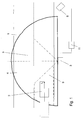
- FIG. 3 a third preferred embodiment of a device according to the invention for carrying out a method for speed measurement is shown.
- the device has a sensor unit 3 for emitting a measuring radiation 4 into a working area 5 determining a maximum measuring range and receiving the measuring radiation reflected on a motor vehicle 2.
- the measuring radiation is a strongly focused pulsed laser beam, which is deflected by a rotating or oscillating mirror in a horizontal scanning plane with a constant scanning frequency and a constant pulse rate and which scans the working area several times.
- a working range with a preferred expansion angle of 10 ° ⁇ ⁇ 60 ° is used for the speed measurement.
- the central axis of the working area is rotated between 15 ° and 40 ° counter to the direction of travel at an acute horizontal angle ⁇ in the direction of the roadway.
- the laser sensor (laser scanner) can be placed next to a roadway 1 at an acute angle to the roadway.
- the laser beam strikes motor vehicles located in the working area 5 and is reflected.
- the respective impact point is described by a measuring point P n .
- the transit time of the pulsed laser beam to the appropriate motor vehicle and back correlates with the traveled distance, from which a distance e n of the measuring point P n of the roadside positioned laser sensor (laser scanner) 3 derived and a time t n and a current scan angle ⁇ n can be assigned.
- a radar sensor which emits a radar lobe which detects a working area with a comparable opening angle.
- the working area 5 has at least a first partial measuring area 9 and a second partial measuring area 8, wherein the size of the second partial measuring area for deriving the traveling speed is selected as a function of the first speed of the motor vehicle 2 derived in the first partial measuring area.
- the estimated speed is derived from the comparison of the transmitted radiation and the radiation reflected by the motor vehicle. For the derivation of the estimated speed, only a few second measured values are needed, which are combined to form a measured value at a time t estim . This is done while entering or passing through the work area, in which it is detected how the contour of the vehicle 2 shifts in the work area over time. In the case of a radar sensor, this is done in the same way on the basis of the second measured values in the form of Doppler signals, which are combined to form a measured value at a time t estim .
- the size of the measuring range in which the first measured values are detected, from which the traveling speed of the same vehicle 2 'is determined at a time t start is determined.
- the shift of the beginning of the first part measuring range is shown, the further the beginning of the first measuring range shifts in the direction of travel, the smaller the first measuring range.
- the travel speed is compared with a limit speed, if the travel speed is greater than the limit speed, a proof is taken by means of a camera 6 when the motor vehicle is on a predetermined photo line 7.
- the camera 6 and the sensor unit 3 are connected to one another via a computer and control unit 11.
- the first partial measuring area 9 is optimally adapted to the speed of the motor vehicle, ie a rather large measuring range for high speeds and a smaller measuring range for low speeds.
- the second partial measuring area 8 is preferably arranged in an entry-side part and the first partial measuring area 9 is arranged in an exit-side part of the working area 5.
- the second part measuring range is formed smaller than the area that is available for the maximum part measuring range.
- the second partial measuring range 8 is preferably only so large that, for all motor vehicles with a maximum speed, e.g. An estimation speed can be determined up to 300 km / h.
- the maximum part between the first part measuring area and the photo line is then available to the first partial measuring area when the photo line 7 is arranged within the working area 5 and at most the area between the second partial measuring area and the edge of the exit side part of the working area 5.
- the first partial measuring area ends irrespective of the estimated speed on the photo line 7 or up to an average vehicle length away from the photo line 71. In practice, depending on the estimated speed, a gap 10 arises between the two partial measuring ranges, which is the smaller, the higher the estimated speed.
- the photo-line 7 comes, in a second embodiment, the photo-line 71 is used.
- the embodiment according to Fig. 4 differs from the first three embodiments by the design of the sensor unit 3.
- the sensor unit comprises a first sensor 3a and a second sensor 3b.
- one sensor is assigned to one partial measuring range 8 in each case.
- the first sensor 3a is assigned to the second partial measuring range and the second sensor 3b is assigned to the first partial measuring range 9.
- the second sensor 3b for the first measuring range in which the driving speed is determined has a higher measuring accuracy than the first sensor 3a.
- the first sensor 3a can be made more cost-effective than the second sensor 3b.
- the two sensors can be brought together at one location and / or in a structural unit or be set up at different locations.
- the two independent sensors can be sensors of the same type, in particular laser scanners or radar sensors.
- the first sensor 3a can also be any other active or passive wave-beam-based sensor, the z. B. works with laser beams, radar beams or sound waves.
- Fig. 4 is also a distance 12 between an end portion of the first part measuring range and the photo line 7 located.
- This distance is inventively chosen relatively small, ideally zero to a maximum of an average vehicle length, so that no further second motor vehicle is erroneously associated with the measured values of the appropriate in the first part measuring range motor vehicle.
Abstract
Die Erfindung betrifft ein Verfahren zur Geschwindigkeitsmessung eines sich auf einer Fahrbahn (1) bewegenden Kraftfahrzeuges (2) mit folgenden Schritten: a) Bereitstellen einer Sensoreinheit (3) zum Aussenden einer Messstrahlung (4) in einen einen maximalen Messbereich bestimmenden Arbeitsbereich (5) und Empfangen einer an dem Kraftfahrzeug reflektierten Messstrahlung; b) Vorgeben einer Anzahl von ersten Messwerten; c) Erfassen von durch die empfangene Messstrahlung in einem ersten Teilmessbereich (8) des Arbeitsbereiches erhaltenen ersten Messwerten; d) Abbrechen des Erfassens an ersten Messwerten gemäß Schritt c), wenn die vorgegebene Anzahl an Messwerten gemäß Schritt b) erreicht wird; e) Ableiten einer Fahrtgeschwindigkeit des sich bewegenden Kraftfahrzeuges aus durch die empfangene Messstrahlung in dem ersten Teilmessbereich (8) des Arbeitsbereiches erhaltenen ersten Messwerten; f) Vergleichen der Fahrtgeschwindigkeit mit einer Grenzgeschwindigkeit; g) Aufnehmen einer Beweisaufnahme mittels einer Kamera (6), falls die Fahrtgeschwindigkeit größer als die Grenzgeschwindigkeit ist.The invention relates to a method for measuring the speed of a motor vehicle (2) moving on a roadway (1), comprising the following steps: a) providing a sensor unit (3) for emitting a measuring radiation (4) into a working range (5) determining a maximum measuring range and receiving a measuring radiation reflected on the motor vehicle; b) specifying a number of first measured values; c) detecting first measured values obtained by the received measuring radiation in a first partial measuring range (8) of the working range; d) stopping the detection at first measured values according to step c), when the predetermined number of measured values according to step b) is reached; e) deriving a traveling speed of the moving motor vehicle from the first measured values obtained by the received measuring radiation in the first partial measuring range (8) of the working range; f) comparing the travel speed with a limit speed; g) taking a proof by means of a camera (6), if the travel speed is greater than the limit speed.
Description
Die vorliegende Erfindung bezieht sich auf ein Verfahren zur Geschwindigkeitsmessung eines sich auf einer Straße bewegenden Kraftfahrzeuges gemäß den Merkmalen von Patentanspruch 1.The present invention relates to a method for measuring the speed of a vehicle moving on a road according to the features of
Insbesondere aus der Verkehrsmesstechnik sind Verfahren und entsprechende Vorrichtungen bekannt, mit denen mittels eines Lasersensors oder Radarsensors ein Arbeitsbereich einer Fahrbahn auf ein Ereignis hin, beispielsweise einen Geschwindigkeitsverstoß eines Kraftfahrzeuges, überwacht wird und im Falle des Eintretens des Ereignisses mittels einer Kamera eine Beweisaufnahme erstellt wird. Hierzu müssen die Position des Kraftfahrzeuges, das den Verstoß begangen hat, indem es beispielsweise mit seiner Fahrtgeschwindigkeit die zugelassene Grenzgeschwindigkeit überschritten hat und die Detektion des Verkehrsverstoßes in einer bestimmten Beziehung zueinander stehen. Daher wird das Kraftfahrzeug oftmals in einer festen Fotolinie mittels der Kamera erfasst.In particular from traffic engineering methods and corresponding devices are known with which by means of a laser sensor or radar sensor a work area of a road towards an event, such as a speed violation of a motor vehicle is monitored and in the event of occurrence of the event by means of a camera evidence is created. For this purpose, the position of the motor vehicle that committed the infringement, for example, has exceeded its speed limit the speed limit allowed and the detection of traffic violation in a certain relationship to each other. Therefore, the motor vehicle is often detected in a fixed photo line by means of the camera.
Bei wellenstrahlbasierten Sensoren, beispielsweise Lasersensoren oder Radarsensoren, in der Verkehrsmesstechnik ist die Güte des Messergebnisses, insbesondere der Fahrtgeschwindigkeit, von der Anzahl der erfassten Messwerte abhängig. Eine geringe Anzahl von erfassten Messwerten liefert oftmals ein ungenaues Messergebnis, eine zu große Anzahl von Messwerten führt bei beschleunigtem oder verzögertem Fahrverhalten des Kraftfahrzeuges zu einem Abbruch der Messung. Aus dem Stand der Technik sind bereits einige Ausführungsformen bekannt, um die Güte der Messergebnisse zu verbessern.In the case of wave-beam-based sensors, for example laser sensors or radar sensors, in traffic measurement technology, the quality of the measurement result, in particular the travel speed, depends on the number of recorded measured values. A small number of recorded measured values often provides an inaccurate measurement result, too large a number of measured values leads to an aborted measurement in the case of accelerated or decelerated driving behavior of the motor vehicle. Some embodiments are already known from the prior art in order to improve the quality of the measurement results.
Aus der
Die
Vor dem Beginn der eigentlichen Messung kann der Entfernungsbereich des Arbeitsbereiches dadurch beschränkt werden, dass er spezifisch für den Aufstellort auf Bereiche angelernt wird, in denen bewegte Objekte erwartet werden. Bei der Messung eines bewegten Objektes werden bei jedem Scan die Messwerte herangezogen, die einen rechten Winkel beschreiben. Hierzu kann der Arbeitsbereich des Laserscanners auf Winkelbereiche beschränkt werden, die Messwerte liefern, die einen rechten Winkel beschreiben.Before starting the actual measurement, the distance range of the working area can be limited by being trained specifically for the installation site to areas in which moving objects are expected. When measuring a moving object, the measured values that describe a right angle are used for each scan. For this purpose, the working range of the laser scanner can be limited to angular ranges that provide measured values that describe a right angle.
Wellenstrahlbasierte Sensoren haben wie der in der
Somit kann die Größe des Arbeitsbereiches nur einen Kompromiss darstellen, wenn sowohl schnelle als auch langsam fahrende Kraftfahrzeuge prozesssicher erfasst werden sollen. Solche Situationen liegen insbesondere auf Autobahnen vor, auf denen beispielsweise bei einem Geschwindigkeitslimit von 80 km/h Lastkraftwagen angemessen werden sollen, die geringfügig die Geschwindigkeitsbegrenzung überschreiten, aber auch stark motorisierte Personenkraftwagen, die um ein vielfaches das Geschwindigkeitslimit überschreiten können.Thus, the size of the work area can only be a compromise if both fast and slow moving vehicles are to be reliably detected. Such situations are particularly prevalent on highways where, for example, at a speed limit of 80 km / h, lorries slightly exceeding the speed limit, but also heavily motorized passenger cars, can exceed the speed limit many times over.
Es ist daher Aufgabe der vorliegenden Erfindung, ein Verfahren zur Geschwindigkeitsmessung eines sich auf einer Straße bewegenden Kraftfahrzeuges zur Verfügung zu stellen, das sowohl für langsam als auch für schnell fahrende Kraftfahrzeuge eine hohe Prozesssicherheit zur Verfügung stellt. Diese Aufgabe wird durch ein Verfahren gemäß Anspruch 1 gelöst. Vorteilhafte Weiterbildungen werden durch die abhängigen Ansprüche näher definiert.It is therefore the object of the present invention to provide a method for measuring the speed of a motor vehicle moving on a road, which provides high process reliability both for slow and fast moving motor vehicles. This object is achieved by a method according to
In einem Grundgedanken der Erfindung weist ein Verfahren zur Geschwindigkeitsmessung eines sich auf einer Fahrbahn bewegenden Kraftfahrzeuges folgende Schritte auf: Bereitstellen einer Sensoreinheit zum Aussenden einer Messstrahlung in einen einen maximalen Messbereich bestimmenden Arbeitsbereich und Empfangen einer an dem Kraftfahrzeug reflektierten Messstrahlung; Vorgeben einer Anzahl von ersten Messwerten; Erfassen von durch die empfangene Messstrahlung in einem ersten Teilmessbereich des Arbeitsbereiches erhaltenen ersten Messwerten; Abbrechen des Erfassens an ersten Messwerten, wenn die vorgegebene Anzahl an Messwerten erreicht wird; Ableiten einer Fahrtgeschwindigkeit des sich bewegenden Kraftfahrzeuges aus durch die empfangene Messstrahlung in dem ersten Teilmessbereich des Arbeitsbereiches erhaltenen ersten Messwerten; Vergleichen der Fahrtgeschwindigkeit mit einer Grenzgeschwindigkeit; Aufnehmen einer Beweisaufnahme mittels einer Kamera, falls die Fahrtgeschwindigkeit größer als die Grenzgeschwindigkeit ist.In one aspect of the invention, a method for measuring the speed of a motor vehicle moving on a road surface comprises the following steps: providing a sensor unit for emitting a measuring radiation into a working range determining a maximum measuring range and receiving a measuring radiation reflected on the motor vehicle; Specify a Number of first measured values; Detecting first measured values obtained by the received measuring radiation in a first partial measuring range of the working range; Canceling the acquisition of first measured values when the predetermined number of measured values is reached; Deriving a traveling speed of the moving motor vehicle from the first measured values obtained by the received measuring radiation in the first partial measuring range of the working range; Comparing the travel speed with a limit speed; Taking a proof by means of a camera, if the travel speed is greater than the limit speed.
Somit wird nicht der Messbereich vor der Messung festgelegt, sondern die Anzahl der Messwerte. Je nach der Fahrtgeschwindigkeit ergeben sich somit für den Messbereich verschiedene Größen. Insgesamt wird durch die erfindungsgemäße Lösung die Gerechtigkeit durch Gleichbehandlung von Geschwindigkeitsverstößen mit geringer Geschwindigkeit und hoher Geschwindigkeit gewährleistet. Bevorzugt erfolgt der Schritt des Aufnehmens einer Beweisaufnahme mit einer Kamera unmittelbar nach dem Vergleichen der Fahrtgeschwindigkeit mit Grenzgeschwindigkeit.Thus, not the measuring range before the measurement is determined, but the number of measured values. Depending on the driving speed, different sizes thus result for the measuring range. Overall, the solution according to the invention ensures fairness by equal treatment of slow speed, high speed speed violations. Preferably, the step of taking a proof is taken with a camera immediately after comparing the travel speed with the limit speed.
In einer weiteren bevorzugten Ausführungsform erfolgt der Schritt des Aufnehmens dann, wenn sich das Kraftfahrzeug an einer vorgegebenen Fotolinie befindet. Es wird also bevorzugt eine derartige Anzahl an Messwerten vorgegeben, so dass die Messung für typische in dem Messbereich vorliegende Geschwindigkeiten abgeschlossen ist, bevor das Kraftfahrzeug den vorgegebenen Fotolinie erreicht.In a further preferred embodiment, the step of picking up takes place when the motor vehicle is on a predetermined photo line. It is thus preferred to specify such a number of measured values, so that the measurement is completed for typical speeds present in the measuring range before the motor vehicle reaches the predetermined photo line.
In einer weiteren besonders bevorzugten Ausführungsform wird eine Schätzgeschwindigkeit zu einem Zeitpunkt t_Schätz des sich bewegenden Kraftfahrzeuges aus durch die empfangene Messstrahlung in einem zweiten Teilmessbereich des Arbeitsbereiches erhaltenen zweiten Messwerten abgeleitet. Zeitlich nachfolgend wird dann das Erfassen von durch die empfangene Messstrahlung in einem ersten Teilmessbereich des Arbeitsbereiches erhaltenen ersten Messwerten zu einem Zeitpunkt t_Start begonnen, so dass das Abbrechen des Erfassens an ersten Messwerten vor der Fotolinie erfolgt. Somit wird durch eine Messung der Geschwindigkeit des Kraftfahrzeuges in einem einfahrtsseitigen Teil des Arbeitsbereiches (zweiter Teilmessbereich) der erste Teilmessbereich optimal an die Geschwindigkeit des Kraftfahrzeuges angepasst, also ein eher großer Messbereich für große Geschwindigkeiten und ein kleinerer Messbereich für kleine Geschwindigkeiten. Bevorzugt ist also der erste Teilmessbereich in einem ausfahrtsseitigen Teil und der zweite Teilmessbereich in einem einfahrtsseitigen Teil des Arbeitsbereiches angeordnet.In a further particularly preferred embodiment, an estimated speed is derived at a time t_recision of the moving motor vehicle from the second measured values obtained by the received measuring radiation in a second partial measuring range of the working range. Subsequently, the acquisition of measured values received by the received measuring radiation in a first partial measuring range of the working range is then started at a time t_Start, so that the detection of the first measured values is stopped before the photo-line. Thus, by measuring the speed of the motor vehicle in an entry-side part of the working area (second partial measuring range), the first partial measuring range is optimally adapted to the speed of the motor vehicle, ie a rather large measuring range for high speeds and a smaller measuring range for low speeds. Preferably, therefore, the first partial measuring range is arranged in an exit-side part and the second partial measuring area is arranged in an entry-side part of the working area.
Unter einer Größe eines Messbereiches ist erfindungsgemäß eine Messlänge zu verstehen, die ein Kraftfahrzeug auf einer Fahrbahn abfährt. Somit werden aus dem maximalen Messbereich, also dem Arbeitsbereich, ein Teilmessbereich oder mehrere Teilmessbereiche herausgeschnitten, in denen die Messwerte zur Ableitung einer Geschwindigkeit herangezogen werden, während in den anderen Bereichen des Arbeitsbereiches die Messwerte verworfen werden. Bevorzugt ist somit der zweite Teilmessbereich kleiner ausgebildet als der erste Teilmessbereich.A size of a measuring range is understood according to the invention to mean a measuring length that a motor vehicle leaves on a roadway. Thus, from the maximum measuring range, ie the working range, one partial measuring range or several partial measuring ranges are cut out, in which the Measurements are used to derive a speed, while in the other areas of the work area, the measured values are discarded. The second partial measuring range is thus preferably smaller than the first partial measuring range.
Bevorzugt kann der Verfahrensschritt des Ableitens der ersten Geschwindigkeit und der Fahrtgeschwindigkeit aus der reflektierten Messstrahlung folgendermaßen erfolgen: Die Messstrahlung kann eine gepulste Laserstrahlung sein, die eine horizontale Scanebene mit einer konstanten Scanfrequenz und einer konstanten Pulsfrequenz mehrfach abscannt. Dazu kann der Lasersensor (Laserscanner) neben einer Fahrbahn in einem spitzen Winkel zur Fahrbahn aufgestellt sein. Während des Scannens trifft der Laserstrahl auf im Arbeitsbereich befindliche Kraftfahrzeuge und wird reflektiert. Der jeweilige Auftreffpunkt wird durch einen Messpunkt Pn beschrieben. Die Laufzeit des gepulsten Laserstrahls zum angemessenen Kraftfahrzeug und zurück korreliert mit der zurückgelegten Wegstrecke, woraus eine Entfernung en des Messpunktes Pn vom am Fahrbahnrand positionierten Lasersensor (Laserscanner) abgeleitet und einem Zeitpunkt tn sowie einem momentanen Scanwinkel εn zugeordnet werden kann.Preferably, the method step of deriving the first speed and the travel speed from the reflected measuring radiation can be carried out as follows: The measuring radiation can be a pulsed laser radiation which scans a horizontal scanning plane repeatedly at a constant scanning frequency and a constant pulse frequency. For this purpose, the laser sensor (laser scanner) can be placed next to a roadway at an acute angle to the roadway. During scanning, the laser beam hits motor vehicles in the work area and is reflected. The respective impact point is described by a measuring point P n . The transit time of the pulsed laser beam to the appropriate motor vehicle and back correlates with the distance traveled, from which a distance e n of the measuring point P n from the roadside positioned laser sensor (laser scanner) derived and a time t n and a current scan angle ε n can be assigned.
Mit den Messwerten für die momentane Entfernungen, und dem momentanen Winkel epsilon und dem Zeitpunkt tn können die Messpunkte Pn mit zeitlicher Zuordnung in einem Polarkoordinatensystem beschrieben werden, das durch den Standort und die Ausrichtung des Lasersensors (Laserscanners) bestimmt ist. Aus diesen Informationen kann nun eine Geschwindigkeit des Kraftfahrzeuges abgeleitet werden.With the measured values for the instantaneous distances, and the instantaneous angle epsilon and the instant t n , the measuring points P n can be described with temporal assignment in a polar coordinate system, which is determined by the location and orientation of the laser sensor (laser scanner). From this information, a speed of the motor vehicle can now be derived.
Alternativ kann die Messstrahlung auch eine Radarstrahlung sein, wobei die Sensoreinheit in diesem Ausführungsbeispiel einen Radarsensor umfasst, der eine Radarkeule aussendet. Die Radarstrahlung wird an sich innerhalb der Radarkeule befindlichen Kraftfahrzeugen reflektiert und aus den Reflexionssignalen beziehungsweise den abgeleiteten Doppler-Signalen werden in bekannter Weise für die jeweiligen Auftreffpunkte am Kraftfahrzeug Wertetripel abgeleitet, die jeweils aus einem Entfernungs- und einem Winkelwert, die gemeinsam die Position des Auftreffpunktes innerhalb der Radarkeule definieren, sowie einem Geschwindigkeitswert bestehen. Bevorzugt werden die erhaltenen Wertetripel, die jeweils durch einen Auftreffpunkt bewirkt werden, zu einem Track zusammengefasst und kontinuierlich auf Plausibilität geprüft (sogenanntes "Trackingverfahren"), indem die Messwerte mit errechneten Sollwerten verglichen werden. Die Sollwerte ergeben sich aus der Annahme, dass ein Kraftfahrzeug nur in begrenztem Maße Richtungsänderungen vornimmt und auch nur in bestimmten Grenzen beschleunigt beziehungsweise verzögert.Alternatively, the measuring radiation may also be radar radiation, wherein the sensor unit in this exemplary embodiment comprises a radar sensor which emits a radar lobe. The radar radiation is reflected on motor vehicles located within the radar lobe, and from the reflection signals or the derived Doppler signals, value triplets are derived in a known manner for the respective impact points on the motor vehicle, each of a distance and an angle value which together determine the position of the impact point within the radar lobe, as well as a speed value. Preferably, the obtained value triplets, which are each effected by a point of impact, are combined to form a track and continuously checked for plausibility (so-called "tracking method") by comparing the measured values with calculated setpoint values. The setpoints result from the assumption that a motor vehicle makes changes in direction only to a limited extent and accelerates or decelerates only within certain limits.
In einer weiteren bevorzugten Ausführungsform kann die Sensoreinheit einen ersten Sensor zum Ableiten der ersten Geschwindigkeit und einen zweiten Sensor zum Ableiten der Fahrtgeschwindigkeit umfassen. Dadurch wird erreicht, dass die erste Geschwindigkeit und die Fahrtgeschwindigkeit unabhängig voneinander gemessen werden können.In a further preferred embodiment, the sensor unit may have a first sensor for deriving the first speed and a second sensor for deriving the travel speed include. This ensures that the first speed and the driving speed can be measured independently of each other.
In einer weiteren bevorzugten Ausführungsform wird die Größe des ersten Teilmessbereiches mit einem ersten Korrekturfaktor angepasst. Da bei sehr schnellen Kraftfahrzeugen kaum starke fahrdynamische Änderungen zu erwarten sind, kann der erste Teilmessbereich durch einen zusätzlichen Faktor vergrößert werden, um Fahrzeuge mit hohen Geschwindigkeiten sicherer erfassen zu können. Auch in Abhängigkeit des Messortes kann ein zusätzlicher Korrekturfaktor in Bezug auf die Abhängigkeit der Schätzgeschwindigkeit nützlich sein, um a priori Wissen zu berücksichtigen, wie beispielsweise an Kreuzungen, die mit Ampeln versehen sind. Dabei kann bei langsamen Kraftfahrzeugen beispielsweise der erste Teilmessbereich vergrößert oder reduziert werden, da bei einem Umschlagen auf Rotlicht eine starke Verzögerung oder Beschleunigung möglich ist.In a further preferred embodiment, the size of the first partial measuring range is adapted with a first correction factor. Since hardly any strong dynamic changes are to be expected in the case of very fast motor vehicles, the first part measuring range can be increased by an additional factor in order to detect vehicles with high speeds more reliably. Depending on the location of the measurement, an additional correction factor with respect to the dependence of the estimated speed may also be useful for taking a priori knowledge into account, such as intersections provided with traffic lights. In this case, in slow vehicles, for example, the first part measuring range can be increased or reduced, since when switching to red light, a strong deceleration or acceleration is possible.
In einer weiteren bevorzugten Ausführungsform umfasst der Schritt des Ableitens einer Fahrtgeschwindigkeit folgende weitere Merkmale: Definieren eines Abbruchkriteriums des Ableitens einer Fahrtgeschwindigkeit wenn eine Streuung der ersten Messwerte oberhalb eines vorgegebenen Grenzwertes liegt; Statistisches Auswerten etwaiger Abbrüche von mehreren Kraftfahrzeugen; Anpassen der Größe des ersten Teilmessbereiches mit einem zweiten Korrekturfaktor, um die Anzahl an Abbrüchen zu reduzieren. Durch eine Reduzierung von Messabbrüchen durch eine zu große Anzahl an Geschwindigkeitsmesswerten kann die Detektionsrate von erfassten Fahrzeugen mit geringer Geschwindigkeit gesteigert werden, ohne das gleichzeitig die Detektionsrate von Fahrzeugen mit hoher Geschwindigkeit sinkt, da eine zu geringe Anzahl von Geschwindigkeitsmesswerten vorliegt. Hierdurch wird ebenfalls die Gerechtigkeit durch Gleichbehandlung von Geschwindigkeitsverstößen mit geringer Geschwindigkeit und hoher Geschwindigkeit gewährleistet. Weiterhin bevorzugt ist der Betrag des vorgegebenen Grenzwertes für die Streuung der ersten Messwerte kleiner oder gleich 3 %.In a further preferred embodiment, the step of deriving a travel speed comprises the following further features: Defining a termination criterion for deriving a travel speed when a scatter of the first measured values is above a predetermined limit value; Statistical analysis of possible crashes of several motor vehicles; Adjusting the size of the first sub-range with a second correction factor to reduce the number of aborts. By reducing measurement crashes due to an excessive number of speed measurements, the detection rate of detected low-speed vehicles can be increased without simultaneously decreasing the detection rate of high-speed vehicles because there are too few speed measurements. This also ensures fairness by equal treatment of slow speed, high speed speed bumps. Further preferably, the amount of the predetermined limit value for the scattering of the first measured values is less than or equal to 3%.
In einer weiteren bevorzugten Ausführungsform ist der erste und/ oder zweite Sensor als Radarsensor oder Lasersensor ausgebildet. Derartige Sensoren sind besonders geeignet, die Geschwindigkeit eines Kraftfahrzeuges zu messen.In a further preferred embodiment, the first and / or second sensor is designed as a radar sensor or laser sensor. Such sensors are particularly suitable for measuring the speed of a motor vehicle.
In einer weiteren bevorzugten Ausführungsform weist der erste Teilmessbereich in Fahrtrichtung einen Anfangsbereich und einen Endbereich auf, wobei ein Abstand zwischen dem Endbereich des ersten Teilmessbereiches und der Fotolinie maximal eine durchschnittliche Länge eines Kraftfahrzeuges beträgt. Wenn der erste Teilmessbereich vor der Fotolinie endet, ist es bevorzugt vorgesehen, dass der Abstand zur Fotolinie derart gering ist, dass wenn ein Kraftfahrzeug im ersten Teilmessbereich angemessen wird, während oder nach dem Messvorgang kein anderes Fahrzeug zwischen dem ersten Teilmessbereich und der Fotolinie einscheren kann und somit beim Auslösen der Beweisaufnahme nicht das eingescherte Kraftfahrzeug fotografisch erfasst und den Messwerten des im ersten Teilmessbereich angemessenen Kraftfahrzeuges fälschlicherweise zugeordnet wird.In a further preferred embodiment, the first part measuring range in the direction of travel on a start region and an end region, wherein a distance between the end portion of the first Teilmessbereiches and the photo line is at most an average length of a motor vehicle. If the first partial measuring range ends before the photo line, it is preferably provided that the distance to the photo line is so small that if a motor vehicle in the first partial measuring range is adequate, during or after the measuring process no other vehicle can engage between the first partial measuring range and the photo line and thus triggering the taking of evidence the retracted motor vehicle is not photographically recorded and incorrectly assigned to the measured values of the motor vehicle suitable for the first part of the measuring range.
Es versteht sich, dass die eben beschriebenen Ausführungsformen in Alleinstellung oder in Kombination untereinander dargestellt werden können. Umfasst eine bevorzugte Ausführungsform eine "und/ oder"-Verknüpfung zwischen einem ersten Merkmal und einem zweiten Merkmal, so ist dies so zu lesen, dass die Ausführungsform sowohl das erste Merkmal als auch das zweite Merkmal und gemäß einer weiteren Ausführungsform entweder nur das erste Merkmal oder nur das zweite Merkmal aufweist.It is understood that the embodiments just described can be presented alone or in combination with each other. If a preferred embodiment comprises a "and / or" link between a first feature and a second feature, then this is to be read so that the embodiment is either the first feature or the second feature and according to another embodiment, either only the first feature or only the second feature.
Vorteilhafte Ausführungsbeispiele der vorliegenden Erfindung werden nachfolgend Bezug nehmend auf die Figuren näher erläutert. Es zeigt:
-
Fig. 1 schematischer Aufbau eines ersten Ausführungsbeispiels einer erfindungsgemäßen Vorrichtung zur Durchführung eines Verfahrens zur Geschwindigkeitsmessung; -
Fig. 2 schematischer Aufbau eines zweiten Ausführungsbeispiels einer erfindungsgemäßen - Vorrichtung zur Durchführung eines Verfahrens zur Geschwindigkeitsmessung;
-
Fig. 3 schematischer Aufbau eines dritten Ausführungsbeispiels einer erfindungsgemäßen Vorrichtung zur Durchführung eines Verfahrens zur Geschwindigkeitsmessung; und -
Fig. 4 schematischer Aufbau eines vierten Ausführungsbeispiels einer erfindungsgemäßen Vorrichtung zur Durchführung eines Verfahrens zur Geschwindigkeitsmessung.
-
Fig. 1 schematic structure of a first embodiment of a device according to the invention for carrying out a method for speed measurement; -
Fig. 2 schematic structure of a second embodiment of an inventive - Apparatus for carrying out a method for speed measurement;
-
Fig. 3 schematic structure of a third embodiment of a device according to the invention for carrying out a method for speed measurement; and -
Fig. 4 schematic structure of a fourth embodiment of a device according to the invention for carrying out a method for speed measurement.
Alternativ kann auch ein Radarsensor eingesetzt werden, der eine Radarkeule abstrahlt, die einen Arbeitsbereich mit einem vergleichbaren Öffnungswinkel erfasst.Alternatively, it is also possible to use a radar sensor which emits a radar lobe which detects a working area with a comparable opening angle.
Mit den Messwerten für die momentane Entfernung, dem momentanen Winkel εn und dem Zeitpunkt tn werden die Messpunkte Pn mit zeitlicher Zuordnung in einem Polarkoordinatensystem beschrieben, das durch den Standort und die Ausrichtung des Lasersensors (Laserscanners) 3 bestimmt ist. Aus diesen Informationen kann nun eine Fahrtgeschwindigkeit des Kraftfahrzeuges abgeleitet werden. Erfindungsgemäß weist der Arbeitsbereich 5 einen ersten Teilmessbereich 9 auf. Bei einem Radarsensor erfolgt dies auf gleiche Weise anhand der ersten Messwerte in Form von Dopplersignalen, die zu einem Messwert zu einem Zeitpunkt t1 zusammengefasst werden.With the measured values for the instantaneous distance, the instantaneous angle ε n and the time t n , the measuring points P n are described with temporal assignment in a polar coordinate system, which is determined by the location and orientation of the laser sensor (laser scanner) 3. From this information, a driving speed of the motor vehicle can now be derived. According to the invention, the working
In dem erfindungsgemäßen Verfahren wird nun eine Anzahl von ersten Messwerten vorgegeben. Wenn durch die empfangene Messstrahlung in dem ersten Teilmessbereich 9 des Arbeitsbereiches erhaltenen ersten Messwerten die vorgegebene Anzahl von ersten Messwerten erreicht wird, wird das Erfassen von ersten Messwerten abgebrochen. Somit wird nicht der Messbereich vor der Messung festgelegt, sondern die Anzahl der Messwerte. Je nach der Fahrtgeschwindigkeit ergeben sich somit für den Messbereich verschiedene Größen. Insgesamt wird durch die erfindungsgemäße Lösung die Gerechtigkeit durch Gleichbehandlung von Geschwindigkeitsverstößen mit geringer Geschwindigkeit und hoher Geschwindigkeit gewährleistet. Aus den erfassten ersten Messwerten wird eine Fahrtgeschwindigkeit des sich bewegenden Kraftfahrzeuges abgeleitet und diese mit einer Grenzgeschwindigkeit verglichen. Wenn dann die Fahrtgeschwindigkeit größer als die Grenzgeschwindigkeit ist, wird mittels einer Kamera 6 eine Beweisaufnahme aufgenommen. Dafür sind die Kamera 6 und die Sensoreinheit 3 über eine Rechner- und Steuereinheit 11 miteinander verbunden.In the method according to the invention, a number of first measured values are now specified. If the predetermined number of first measured values is reached by the received measuring radiation in the first
Im Unterschied zum Ausführungsbeispiel gemäß
Aus dem Vergleich der gesendeten Strahlung und der am Kraftfahrzeug 2 reflektierten Strahlung wird die Schätzgeschwindigkeit abgeleitet. Für die Ableitung der Schätzgeschwindigkeit werden nur einige wenige zweite Messwerte benötigt, die zu einem Messwert zu einem Zeitpunkt tSchätz zusammengefasst werden. Dies erfolgt während der Einfahrt in den oder der Durchfahrt durch den Arbeitsbereich, bei der erfasst wird, wie sich die Kontur des Fahrzeuges im Arbeitsbereich über die Zeit verschiebt. Bei einem Radarsensor erfolgt dies auf gleiche Weise anhand der zweiten Messwerte in Form von Dopplersignalen, die zu einem Messwert zu einem Zeitpunkt tSchätz zusammengefasst werden. Anhand der Schätzgeschwindigkeit des sich bewegenden Kraftfahrzeuges wird die Größe des Messbereiches, in dem die ersten Messwerte erfasst werden, bestimmt. Dies geschieht durch Festlegung des Zeitpunktes tStart, an dem die Erfassung der ersten Messwerte beginnt. Durch den Pfeil Z ist die zeitliche Verschiebung des Beginns des ersten Teilmessbereiches für unterschiedliche Schätzgeschwindigkeiten dargestellt. Dies bedeutet, dass sich der Beginn des ersten Messbereiches in Fahrtrichtung verschiebt. Anschließend wird die Fahrtgeschwindigkeit mit einer Grenzgeschwindigkeit verglichen. Wenn die Fahrtgeschwindigkeit größer als die Grenzgeschwindigkeit ist, wird mittels einer Kamera 6 eine Beweisaufnahme ausgelöst, wenn sich das Kraftfahrzeug an einer vorgegebenen Fotolinie 7 befindet. Dafür sind die Kamera 6 und die Sensoreinheit 3 über eine Rechner- und Steuereinheit 11 miteinander verbunden.From the comparison of the transmitted radiation and the radiation reflected on the
Durch die Messung einer Schätzgeschwindigkeit des Kraftfahrzeuges in dem einfahrtsseitigen Teil des Arbeitsbereiches (zweiter Teilmessbereich 8) wird der erste Teilmessbereich 9 optimal an die Geschwindigkeit des Kraftfahrzeuges angepasst, also ein eher großer Messbereich für große Geschwindigkeiten und ein kleinerer Messbereich für kleine Geschwindigkeiten. Bevorzugt ist also der zweite Teilmessbereich 8 in einem einfahrtsseitigen Teil und der erste Teilmessbereich 9 in einem ausfahrtsseitigen Teil des Arbeitsbereiches 5 angeordnet.By measuring an estimated speed of the motor vehicle in the entry-side part of the working area (second partial measuring area 8), the first
Unter der Größe des Messbereiches ist erfindungsgemäß die Messlänge zu verstehen, die das Kraftfahrzeug 2 auf einer Fahrbahn 1 abfährt. Somit werden in dem maximalen Messbereich, also dem Arbeitsbereich 5, Teilmessbereiche definiert, in denen die Messwerte zur Ableitung einer Geschwindigkeit herangezogen werden, während in den anderen Bereichen des Arbeitsbereiches die Messwerte für die Bestimmung der Fahrtgeschwindigkeit ungenutzt bleiben.According to the invention, the size of the measuring range is understood to mean the measuring length which the
Der erste Teilmessbereich endet unabhängig von der Schätzgeschwindigkeit an oder bis zu einer durchschnittlichen Fahrzeuglänge entfernt vor der Fotolinie 7. In der Praxis entsteht somit in Abhängigkeit der Schätzgeschwindigkeit eine Lücke 10 zwischen den beiden Teilmessbereichen, die umso kleiner ist, je höher die Schätzgeschwindigkeit ist.The first partial measuring range ends independently of the estimated speed at or up to an average vehicle length away from the
In der
Die Vorrichtung weist eine Sensoreinheit 3 zum Aussenden einer Messstrahlung 4 in einen, einen maximalen Messbereich bestimmenden Arbeitsbereich 5 und Empfangen der an einem Kraftfahrzeug 2 reflektierten Messstrahlung auf. Die Messstrahlung ist ein stark fokussierter gepulster Laserstrahl, der über einen rotierenden oder schwingenden Spiegel in einer horizontalen Scanebene mit einer konstanten Scanfrequenz und mit einer konstanten Pulsfrequenz abgelenkt wird und den Arbeitsbereich mehrfach abscannt. Hierbei wird für die Geschwindigkeitsmessung ein Arbeitsbereich mit einem bevorzugten Aufweitungswinkel von 10°< α <60° eingesetzt. Die Mittelachse des Arbeitsbereiches ist dabei je nach Messsituation zwischen 15° und 40° entgegen der Fahrrichtung in einem spitzen horizontalen Winkel β in Richtung der Fahrbahn gedreht. Dazu kann der Lasersensor (Laserscanner) neben einer Fahrbahn 1 in einem spitzen Winkel zur Fahrbahn aufgestellt sein. Während des Scannens trifft der Laserstrahl auf im Arbeitsbereich 5 befindliche Kraftfahrzeuge und wird reflektiert. Der jeweilige Auftreffpunkt wird durch einen Messpunkt Pn beschrieben. Die Laufzeit des gepulsten Laserstrahls zum angemessenen Kraftfahrzeug und zurück korreliert mit der zurückgelegten Wegstrecke, woraus eine Entfernung en des Messpunktes Pn vom am Fahrbahnrand positionierten Lasersensor (Laserscanner) 3 abgeleitet und einem Zeitpunkt tn sowie einem momentanen Scanwinkel εn zugeordnet werden kann.The device has a
Alternativ kann auch ein Radarsensor eingesetzt werden, der eine Radarkeule abstrahlt, die einen Arbeitsbereich mit einem vergleichbaren Öffnungswinkel erfasst.Alternatively, it is also possible to use a radar sensor which emits a radar lobe which detects a working area with a comparable opening angle.
Mit den Messwerten für die momentane Entfernung, dem momentanen Winkel εn und dem Zeitpunkt tn werden die Messpunkte Pn mit zeitlicher Zuordnung in einem Polarkoordinatensystem beschrieben, das durch den Standort und die Ausrichtung des Lasersensors (Laserscanners) 3 bestimmt ist. Aus diesen Informationen kann nun eine Geschwindigkeit des Kraftfahrzeuges abgeleitet werden. Erfindungsgemäß weist der Arbeitsbereich 5 zumindest einen ersten Teilmessbereich 9 und einen zweiten Teilmessbereich 8 auf, wobei die Größe des zweiten Teilmessbereiches zum Ableiten der Fahrtgeschwindigkeit in Abhängigkeit der in dem ersten Teilmessbereich abgeleiteten ersten Geschwindigkeit des Kraftfahrzeuges 2 gewählt wird.With the measured values for the instantaneous distance, the instantaneous angle ε n and the time t n , the measuring points P n are described with temporal assignment in a polar coordinate system, which is determined by the location and orientation of the laser sensor (laser scanner) 3. From this information, a speed of the motor vehicle can now be derived. According to the invention, the working
Aus dem Vergleich der gesendeten Strahlung und der am Kraftfahrzeug reflektierten Strahlung wird die Schätzgeschwindigkeit abgeleitet. Für die Ableitung der Schätzgeschwindigkeit werden nur einige wenige zweite Messwerte benötigt, die zu einem Messwert zu einem Zeitpunkt tSchätz zusammengefasst werden. Dies erfolgt während der Einfahrt in den oder der Durchfahrt durch den Arbeitsbereich, bei der erfasst wird, wie sich die Kontur des Fahrzeuges 2 im Arbeitsbereich über die Zeit verschiebt. Bei einem Radarsensor erfolgt dies auf gleiche Weise anhand der zweiten Messwerte in Form von Dopplersignalen, die zu einem Messwert zu einem Zeitpunkt tSchätz zusammengefasst werden. Anhand der Schätzgeschwindigkeit des sich bewegenden Kraftfahrzeuges wird die Größe des Messbereiches, in dem die ersten Messwerte erfasst werden, aus denen die Fahrtgeschwindigkeit des gleichen Fahrzeuges 2' zu einem Zeitpunkt tStart bestimmt wird, festgelegt. Durch den Pfeil Z ist die Verschiebung des Beginns des ersten Teilmessbereiches dargestellt, je weiter sich der Beginn des ersten Messbereiches in Fahrtrichtung verschiebt, umso kleiner wird der erste Messbereich. Anschließend wird die Fahrtgeschwindigkeit mit einer Grenzgeschwindigkeit verglichen, wenn die Fahrtgeschwindigkeit größer als die Grenzgeschwindigkeit ist, wird mittels einer Kamera 6 eine Beweisaufnahme ausgelöst, wenn sich das Kraftfahrzeug an einer vorgegebenen Fotolinie 7 befindet. Dafür sind die Kamera 6 und die Sensoreinheit 3 über eine Rechner- und Steuereinheit 11 miteinander verbunden.The estimated speed is derived from the comparison of the transmitted radiation and the radiation reflected by the motor vehicle. For the derivation of the estimated speed, only a few second measured values are needed, which are combined to form a measured value at a time t estim . This is done while entering or passing through the work area, in which it is detected how the contour of the
Durch die Messung einer Schätzgeschwindigkeit des Kraftfahrzeuges in dem einfahrtsseitigen Teil des Arbeitsbereiches (zweiter Teilmessbereich 8) wird der erste Teilmessbereich 9 optimal an die Geschwindigkeit des Kraftfahrzeuges angepasst, also ein eher großer Messbereich für große Geschwindigkeiten und ein kleinerer Messbereich für kleine Geschwindigkeiten. Bevorzugt ist also der zweite Teilmessbereich 8 in einem einfahrtsseitigen Teil und der erste Teilmessbereich 9 in einem ausfahrtsseitigen Teil des Arbeitsbereiches 5 angeordnet.By measuring an estimated speed of the motor vehicle in the entry-side part of the working area (second partial measuring area 8), the first
Bevorzugt ist somit der zweite Teilmessbereich kleiner ausgebildet als der Bereich, der maximal für den ersten Teilmessbereich zur Verfügung steht. Der zweite Teilmessbereich 8 ist bevorzugt nur so groß, dass für alle Kraftfahrzeuge mit einer maximal vorgesehen Geschwindigkeit z.B. bis 300 km/h eine Schätzgeschwindigkeit bestimmt werden kann. Dem ersten Teilmessbereich stehen dann maximal der Bereich zwischen dem ersten Teilmessbereich und der Fotolinie zur Verfügung, wenn die Fotolinie 7 innerhalb des Arbeitsbereiches 5 angeordnet ist und maximal der Bereich zwischen dem zweiten Teilmessbereich und dem Rand des ausfahrtseitigen Teils des Arbeitsbereiches 5. Der erste Teilmessbereich endet unabhängig von der Schätzgeschwindigkeit an der Fotolinie 7 oder bis zu einer durchschnittlichen Fahrzeuglänge entfernt vor der Fotolinie 71. In der Praxis entsteht somit in Abhängigkeit der Schätzgeschwindigkeit eine Lücke 10 zwischen den beiden Teilmessbereichen, die umso kleiner ist, je höher die Schätzgeschwindigkeit ist. In einer ersten Ausführungsform kommt die Fotolinie 7, in einer zweiten Ausführungsform kommt die Fotolinie 71 zum Einsatz.Preferably, therefore, the second part measuring range is formed smaller than the area that is available for the maximum part measuring range. The second
In der
Das Ausführungsbeispiel gemäß
Die beiden Sensoren können an einem Ort und/ oder in einer Baueinheit zusammengeführt sein oder an verschiedenen Orten aufgestellt sein. Beispielsweise kann es sich bei den beiden unabhängigen Sensoren um Sensoren gleicher Art, insbesondere Laserscanner oder Radarsensoren handeln. Der erste Sensor 3a kann aber auch ein beliebig anderer aktiver oder passiver wellenstrahlbasierter Sensor sein, der z. B. mit Laserstrahlen, Radarstrahlen oder Schallwellen arbeitet.The two sensors can be brought together at one location and / or in a structural unit or be set up at different locations. For example, the two independent sensors can be sensors of the same type, in particular laser scanners or radar sensors. However, the
In der
Grundsätzlich können die Ausführungsbeispiele 2 und 3 wie in
Claims (9)
Messwerte oberhalb eines vorgegebenen Grenzwertes liegt;
um die Anzahl an Abbrüchen zu reduzieren.
Measured values is above a predetermined limit value;
to reduce the number of crashes.
Applications Claiming Priority (1)
| Application Number | Priority Date | Filing Date | Title |
|---|---|---|---|
| DE102013019801.1A DE102013019801B4 (en) | 2013-11-27 | 2013-11-27 | Method for measuring the speed of a motor vehicle moving on a road |
Publications (2)
| Publication Number | Publication Date |
|---|---|
| EP2878971A1 true EP2878971A1 (en) | 2015-06-03 |
| EP2878971B1 EP2878971B1 (en) | 2021-12-29 |
Family
ID=51897058
Family Applications (1)
| Application Number | Title | Priority Date | Filing Date |
|---|---|---|---|
| EP14003812.6A Active EP2878971B1 (en) | 2013-11-27 | 2014-11-12 | Method for measuring the speed of a motor vehicle moving along a road |
Country Status (2)
| Country | Link |
|---|---|
| EP (1) | EP2878971B1 (en) |
| DE (1) | DE102013019801B4 (en) |
Families Citing this family (1)
| Publication number | Priority date | Publication date | Assignee | Title |
|---|---|---|---|---|
| FR3086066B1 (en) * | 2018-09-13 | 2021-01-29 | Idemia Identity & Security France | METHOD AND DEVICE FOR MONITORING THE OPERATION OF A ROAD RADAR. |
Citations (9)
| Publication number | Priority date | Publication date | Assignee | Title |
|---|---|---|---|---|
| EP0286910A2 (en) | 1987-04-11 | 1988-10-19 | Robot Foto & Electronic GmbH & Co KG | Traffic surveillance device |
| DE3908785A1 (en) * | 1989-03-17 | 1990-09-27 | Bke Bildtechnisches Konstrukti | Method and devices for measuring the speed of motor vehicles |
| US6160494A (en) * | 1996-07-26 | 2000-12-12 | Sodi; Paolo | Machine and method for detecting traffic offenses with dynamic aiming systems |
| US20040174294A1 (en) * | 2003-01-10 | 2004-09-09 | Wavetronix | Systems and methods for monitoring speed |
| DE102007038364A1 (en) | 2007-08-10 | 2009-02-12 | Robot Visual Systems Gmbh | Method for measuring the speed of vehicles by means of a laser scanner |
| US20110187580A1 (en) * | 2007-10-09 | 2011-08-04 | Guy Laenen | Device for detecting a vehicle on an airport runway |
| DE102010010656A1 (en) * | 2010-03-09 | 2011-09-15 | Rtb Gmbh & Co. Kg | Method for classifying cars in road traffic for determining length of cars, involves recognizing car position from position of right rear and front edges of cars, and determining distance of car axles from right front edge radar module |
| US20120188115A1 (en) * | 2011-01-24 | 2012-07-26 | Lang Hong | Using Forward-Look and Side-Look Doppler Radars for Precise Vehicle Association in Automated Traffic Surveillance |
| EP2650696A1 (en) * | 2012-03-26 | 2013-10-16 | Sierzega Elektronik GmbH | Method and device for radar traffic detection |
-
2013
- 2013-11-27 DE DE102013019801.1A patent/DE102013019801B4/en active Active
-
2014
- 2014-11-12 EP EP14003812.6A patent/EP2878971B1/en active Active
Patent Citations (9)
| Publication number | Priority date | Publication date | Assignee | Title |
|---|---|---|---|---|
| EP0286910A2 (en) | 1987-04-11 | 1988-10-19 | Robot Foto & Electronic GmbH & Co KG | Traffic surveillance device |
| DE3908785A1 (en) * | 1989-03-17 | 1990-09-27 | Bke Bildtechnisches Konstrukti | Method and devices for measuring the speed of motor vehicles |
| US6160494A (en) * | 1996-07-26 | 2000-12-12 | Sodi; Paolo | Machine and method for detecting traffic offenses with dynamic aiming systems |
| US20040174294A1 (en) * | 2003-01-10 | 2004-09-09 | Wavetronix | Systems and methods for monitoring speed |
| DE102007038364A1 (en) | 2007-08-10 | 2009-02-12 | Robot Visual Systems Gmbh | Method for measuring the speed of vehicles by means of a laser scanner |
| US20110187580A1 (en) * | 2007-10-09 | 2011-08-04 | Guy Laenen | Device for detecting a vehicle on an airport runway |
| DE102010010656A1 (en) * | 2010-03-09 | 2011-09-15 | Rtb Gmbh & Co. Kg | Method for classifying cars in road traffic for determining length of cars, involves recognizing car position from position of right rear and front edges of cars, and determining distance of car axles from right front edge radar module |
| US20120188115A1 (en) * | 2011-01-24 | 2012-07-26 | Lang Hong | Using Forward-Look and Side-Look Doppler Radars for Precise Vehicle Association in Automated Traffic Surveillance |
| EP2650696A1 (en) * | 2012-03-26 | 2013-10-16 | Sierzega Elektronik GmbH | Method and device for radar traffic detection |
Also Published As
| Publication number | Publication date |
|---|---|
| EP2878971B1 (en) | 2021-12-29 |
| DE102013019801B4 (en) | 2018-01-11 |
| DE102013019801A1 (en) | 2015-05-28 |
Similar Documents
| Publication | Publication Date | Title |
|---|---|---|
| EP1990654B1 (en) | Method and device for determining the automobile class of automobiles | |
| EP1990655B1 (en) | Method for conclusively determining the speed of a vehicle | |
| DE102012107444B3 (en) | Method for classifying traveling vehicles e.g. passenger car, by tracking vehicle position magnitude in flowing traffic, involves comparing discontinuity portion length with stored typical velocity-normalized lengths to classify vehicle | |
| DE19743255B4 (en) | Detection system for moving objects for motor vehicles | |
| EP2048515B1 (en) | Method for determining and documenting traffic violations at a traffic light | |
| EP0286910B1 (en) | Traffic surveillance device | |
| EP3058391B1 (en) | Use of a method and of an apparatus for classification of obstacles | |
| EP2106530B1 (en) | Method and device for sensing the three-dimensional surface of an object, in particular of a vehicle tire | |
| DE112017003974B4 (en) | speed control device | |
| EP0936471A2 (en) | Vehicle with object detecting device | |
| EP2778714B1 (en) | Method for detecting traffic offences in an area with traffic lights by measuring the rear of vehicles using a radar device | |
| DE102018201220A1 (en) | Distance detection system, method for a distance detection system and vehicle | |
| DE19947593A1 (en) | Radar equipment for motor vehicle has ghost echo detector that detects ghost echo if distance and relative speed of second radar image are same as for first image | |
| EP2804014B1 (en) | Device and method for determining a characteristic of a vehicle | |
| EP2221640B1 (en) | Method for measuring the speed of a vehicle and visual allocation in documentation | |
| DE102007038364A1 (en) | Method for measuring the speed of vehicles by means of a laser scanner | |
| EP2341367B1 (en) | Method and assembly for detecting traffic violations in an area with traffic lights | |
| EP3193276A1 (en) | Detection device and method for detecting vehicle axles | |
| EP2306217B1 (en) | Environment recording | |
| DE102013019801B4 (en) | Method for measuring the speed of a motor vehicle moving on a road | |
| EP2656105B1 (en) | Method for generating an image document in which a vehicle measured by a radar device can be identified and image document generated with this method | |
| DE10320723B4 (en) | Measuring device in motor vehicles for measuring parking spaces and method for measuring parking spaces | |
| EP3433632B1 (en) | Method for capturing at least one object, apparatus of a sensor device, sensor device, and driver assistance system having at least one sensor device | |
| DE102006015036A1 (en) | Rail monitoring method for rail vehicle, involves defining monitoring boundaries at sides of rail, diagonally scanning cross line between points on respective boundaries, and diagonally and longitudinally scanning left monitoring boundary | |
| DE102015118080B4 (en) | Detecting a movement of a land vehicle and land vehicle with motion detection device |
Legal Events
| Date | Code | Title | Description |
|---|---|---|---|
| PUAI | Public reference made under article 153(3) epc to a published international application that has entered the european phase |
Free format text: ORIGINAL CODE: 0009012 |
|
| 17P | Request for examination filed |
Effective date: 20141112 |
|
| AK | Designated contracting states |
Kind code of ref document: A1 Designated state(s): AL AT BE BG CH CY CZ DE DK EE ES FI FR GB GR HR HU IE IS IT LI LT LU LV MC MK MT NL NO PL PT RO RS SE SI SK SM TR |
|
| AX | Request for extension of the european patent |
Extension state: BA ME |
|
| R17P | Request for examination filed (corrected) |
Effective date: 20150909 |
|
| RBV | Designated contracting states (corrected) |
Designated state(s): AL AT BE BG CH CY CZ DE DK EE ES FI FR GB GR HR HU IE IS IT LI LT LU LV MC MK MT NL NO PL PT RO RS SE SI SK SM TR |
|
| STAA | Information on the status of an ep patent application or granted ep patent |
Free format text: STATUS: EXAMINATION IS IN PROGRESS |
|
| 17Q | First examination report despatched |
Effective date: 20170920 |
|
| STAA | Information on the status of an ep patent application or granted ep patent |
Free format text: STATUS: EXAMINATION IS IN PROGRESS |
|
| GRAP | Despatch of communication of intention to grant a patent |
Free format text: ORIGINAL CODE: EPIDOSNIGR1 |
|
| STAA | Information on the status of an ep patent application or granted ep patent |
Free format text: STATUS: GRANT OF PATENT IS INTENDED |
|
| INTG | Intention to grant announced |
Effective date: 20210913 |
|
| GRAS | Grant fee paid |
Free format text: ORIGINAL CODE: EPIDOSNIGR3 |
|
| GRAA | (expected) grant |
Free format text: ORIGINAL CODE: 0009210 |
|
| STAA | Information on the status of an ep patent application or granted ep patent |
Free format text: STATUS: THE PATENT HAS BEEN GRANTED |
|
| AK | Designated contracting states |
Kind code of ref document: B1 Designated state(s): AL AT BE BG CH CY CZ DE DK EE ES FI FR GB GR HR HU IE IS IT LI LT LU LV MC MK MT NL NO PL PT RO RS SE SI SK SM TR |
|
| REG | Reference to a national code |
Ref country code: GB Ref legal event code: FG4D Free format text: NOT ENGLISH |
|
| REG | Reference to a national code |
Ref country code: CH Ref legal event code: EP |
|
| REG | Reference to a national code |
Ref country code: AT Ref legal event code: REF Ref document number: 1459089 Country of ref document: AT Kind code of ref document: T Effective date: 20220115 |
|
| REG | Reference to a national code |
Ref country code: IE Ref legal event code: FG4D Free format text: LANGUAGE OF EP DOCUMENT: GERMAN |
|
| REG | Reference to a national code |
Ref country code: DE Ref legal event code: R096 Ref document number: 502014016052 Country of ref document: DE |
|
| REG | Reference to a national code |
Ref country code: LT Ref legal event code: MG9D |
|
| PG25 | Lapsed in a contracting state [announced via postgrant information from national office to epo] |
Ref country code: RS Free format text: LAPSE BECAUSE OF FAILURE TO SUBMIT A TRANSLATION OF THE DESCRIPTION OR TO PAY THE FEE WITHIN THE PRESCRIBED TIME-LIMIT Effective date: 20211229 Ref country code: LT Free format text: LAPSE BECAUSE OF FAILURE TO SUBMIT A TRANSLATION OF THE DESCRIPTION OR TO PAY THE FEE WITHIN THE PRESCRIBED TIME-LIMIT Effective date: 20211229 Ref country code: FI Free format text: LAPSE BECAUSE OF FAILURE TO SUBMIT A TRANSLATION OF THE DESCRIPTION OR TO PAY THE FEE WITHIN THE PRESCRIBED TIME-LIMIT Effective date: 20211229 Ref country code: BG Free format text: LAPSE BECAUSE OF FAILURE TO SUBMIT A TRANSLATION OF THE DESCRIPTION OR TO PAY THE FEE WITHIN THE PRESCRIBED TIME-LIMIT Effective date: 20220329 |
|
| REG | Reference to a national code |
Ref country code: NL Ref legal event code: MP Effective date: 20211229 |
|
| PG25 | Lapsed in a contracting state [announced via postgrant information from national office to epo] |
Ref country code: SE Free format text: LAPSE BECAUSE OF FAILURE TO SUBMIT A TRANSLATION OF THE DESCRIPTION OR TO PAY THE FEE WITHIN THE PRESCRIBED TIME-LIMIT Effective date: 20211229 Ref country code: NO Free format text: LAPSE BECAUSE OF FAILURE TO SUBMIT A TRANSLATION OF THE DESCRIPTION OR TO PAY THE FEE WITHIN THE PRESCRIBED TIME-LIMIT Effective date: 20220329 Ref country code: LV Free format text: LAPSE BECAUSE OF FAILURE TO SUBMIT A TRANSLATION OF THE DESCRIPTION OR TO PAY THE FEE WITHIN THE PRESCRIBED TIME-LIMIT Effective date: 20211229 Ref country code: HR Free format text: LAPSE BECAUSE OF FAILURE TO SUBMIT A TRANSLATION OF THE DESCRIPTION OR TO PAY THE FEE WITHIN THE PRESCRIBED TIME-LIMIT Effective date: 20211229 Ref country code: GR Free format text: LAPSE BECAUSE OF FAILURE TO SUBMIT A TRANSLATION OF THE DESCRIPTION OR TO PAY THE FEE WITHIN THE PRESCRIBED TIME-LIMIT Effective date: 20220330 |
|
| PG25 | Lapsed in a contracting state [announced via postgrant information from national office to epo] |
Ref country code: NL Free format text: LAPSE BECAUSE OF FAILURE TO SUBMIT A TRANSLATION OF THE DESCRIPTION OR TO PAY THE FEE WITHIN THE PRESCRIBED TIME-LIMIT Effective date: 20211229 |
|
| PG25 | Lapsed in a contracting state [announced via postgrant information from national office to epo] |
Ref country code: SM Free format text: LAPSE BECAUSE OF FAILURE TO SUBMIT A TRANSLATION OF THE DESCRIPTION OR TO PAY THE FEE WITHIN THE PRESCRIBED TIME-LIMIT Effective date: 20211229 Ref country code: SK Free format text: LAPSE BECAUSE OF FAILURE TO SUBMIT A TRANSLATION OF THE DESCRIPTION OR TO PAY THE FEE WITHIN THE PRESCRIBED TIME-LIMIT Effective date: 20211229 Ref country code: RO Free format text: LAPSE BECAUSE OF FAILURE TO SUBMIT A TRANSLATION OF THE DESCRIPTION OR TO PAY THE FEE WITHIN THE PRESCRIBED TIME-LIMIT Effective date: 20211229 Ref country code: PT Free format text: LAPSE BECAUSE OF FAILURE TO SUBMIT A TRANSLATION OF THE DESCRIPTION OR TO PAY THE FEE WITHIN THE PRESCRIBED TIME-LIMIT Effective date: 20220429 Ref country code: ES Free format text: LAPSE BECAUSE OF FAILURE TO SUBMIT A TRANSLATION OF THE DESCRIPTION OR TO PAY THE FEE WITHIN THE PRESCRIBED TIME-LIMIT Effective date: 20211229 Ref country code: EE Free format text: LAPSE BECAUSE OF FAILURE TO SUBMIT A TRANSLATION OF THE DESCRIPTION OR TO PAY THE FEE WITHIN THE PRESCRIBED TIME-LIMIT Effective date: 20211229 Ref country code: CZ Free format text: LAPSE BECAUSE OF FAILURE TO SUBMIT A TRANSLATION OF THE DESCRIPTION OR TO PAY THE FEE WITHIN THE PRESCRIBED TIME-LIMIT Effective date: 20211229 |
|
| PG25 | Lapsed in a contracting state [announced via postgrant information from national office to epo] |
Ref country code: PL Free format text: LAPSE BECAUSE OF FAILURE TO SUBMIT A TRANSLATION OF THE DESCRIPTION OR TO PAY THE FEE WITHIN THE PRESCRIBED TIME-LIMIT Effective date: 20211229 |
|
| PG25 | Lapsed in a contracting state [announced via postgrant information from national office to epo] |
Ref country code: IS Free format text: LAPSE BECAUSE OF FAILURE TO SUBMIT A TRANSLATION OF THE DESCRIPTION OR TO PAY THE FEE WITHIN THE PRESCRIBED TIME-LIMIT Effective date: 20220429 |
|
| REG | Reference to a national code |
Ref country code: DE Ref legal event code: R097 Ref document number: 502014016052 Country of ref document: DE |
|
| PG25 | Lapsed in a contracting state [announced via postgrant information from national office to epo] |
Ref country code: DK Free format text: LAPSE BECAUSE OF FAILURE TO SUBMIT A TRANSLATION OF THE DESCRIPTION OR TO PAY THE FEE WITHIN THE PRESCRIBED TIME-LIMIT Effective date: 20211229 Ref country code: AL Free format text: LAPSE BECAUSE OF FAILURE TO SUBMIT A TRANSLATION OF THE DESCRIPTION OR TO PAY THE FEE WITHIN THE PRESCRIBED TIME-LIMIT Effective date: 20211229 |
|
| PLBE | No opposition filed within time limit |
Free format text: ORIGINAL CODE: 0009261 |
|
| STAA | Information on the status of an ep patent application or granted ep patent |
Free format text: STATUS: NO OPPOSITION FILED WITHIN TIME LIMIT |
|
| 26N | No opposition filed |
Effective date: 20220930 |
|
| PG25 | Lapsed in a contracting state [announced via postgrant information from national office to epo] |
Ref country code: SI Free format text: LAPSE BECAUSE OF FAILURE TO SUBMIT A TRANSLATION OF THE DESCRIPTION OR TO PAY THE FEE WITHIN THE PRESCRIBED TIME-LIMIT Effective date: 20211229 |
|
| PG25 | Lapsed in a contracting state [announced via postgrant information from national office to epo] |
Ref country code: IT Free format text: LAPSE BECAUSE OF FAILURE TO SUBMIT A TRANSLATION OF THE DESCRIPTION OR TO PAY THE FEE WITHIN THE PRESCRIBED TIME-LIMIT Effective date: 20211229 |
|
| PG25 | Lapsed in a contracting state [announced via postgrant information from national office to epo] |
Ref country code: MC Free format text: LAPSE BECAUSE OF FAILURE TO SUBMIT A TRANSLATION OF THE DESCRIPTION OR TO PAY THE FEE WITHIN THE PRESCRIBED TIME-LIMIT Effective date: 20211229 |
|
| REG | Reference to a national code |
Ref country code: BE Ref legal event code: MM Effective date: 20221130 |
|
| PG25 | Lapsed in a contracting state [announced via postgrant information from national office to epo] |
Ref country code: LU Free format text: LAPSE BECAUSE OF NON-PAYMENT OF DUE FEES Effective date: 20221112 |
|
| PG25 | Lapsed in a contracting state [announced via postgrant information from national office to epo] |
Ref country code: IE Free format text: LAPSE BECAUSE OF NON-PAYMENT OF DUE FEES Effective date: 20221112 |
|
| PG25 | Lapsed in a contracting state [announced via postgrant information from national office to epo] |
Ref country code: BE Free format text: LAPSE BECAUSE OF NON-PAYMENT OF DUE FEES Effective date: 20221130 |
|
| PGFP | Annual fee paid to national office [announced via postgrant information from national office to epo] |
Ref country code: GB Payment date: 20231123 Year of fee payment: 10 |
|
| PGFP | Annual fee paid to national office [announced via postgrant information from national office to epo] |
Ref country code: FR Payment date: 20231122 Year of fee payment: 10 Ref country code: DE Payment date: 20231120 Year of fee payment: 10 Ref country code: CH Payment date: 20231201 Year of fee payment: 10 Ref country code: AT Payment date: 20231117 Year of fee payment: 10 |
|
| PG25 | Lapsed in a contracting state [announced via postgrant information from national office to epo] |
Ref country code: HU Free format text: LAPSE BECAUSE OF FAILURE TO SUBMIT A TRANSLATION OF THE DESCRIPTION OR TO PAY THE FEE WITHIN THE PRESCRIBED TIME-LIMIT; INVALID AB INITIO Effective date: 20141112 |