EP2881046A2 - Adapter assembly for interconnecting electromechanical surgical devices and surgical loading units, and surgical systems thereof - Google Patents
Adapter assembly for interconnecting electromechanical surgical devices and surgical loading units, and surgical systems thereof Download PDFInfo
- Publication number
- EP2881046A2 EP2881046A2 EP14196833.9A EP14196833A EP2881046A2 EP 2881046 A2 EP2881046 A2 EP 2881046A2 EP 14196833 A EP14196833 A EP 14196833A EP 2881046 A2 EP2881046 A2 EP 2881046A2
- Authority
- EP
- European Patent Office
- Prior art keywords
- force
- assembly
- rotation
- drive shaft
- proximal
- Prior art date
- Legal status (The legal status is an assumption and is not a legal conclusion. Google has not performed a legal analysis and makes no representation as to the accuracy of the status listed.)
- Granted
Links
- 238000004891 communication Methods 0.000 claims description 11
- 230000000295 complement effect Effects 0.000 claims description 6
- 230000000712 assembly Effects 0.000 abstract description 14
- 238000000429 assembly Methods 0.000 abstract description 14
- 230000008878 coupling Effects 0.000 description 14
- 238000010168 coupling process Methods 0.000 description 14
- 238000005859 coupling reaction Methods 0.000 description 14
- 230000007246 mechanism Effects 0.000 description 9
- 230000005484 gravity Effects 0.000 description 6
- 230000003014 reinforcing effect Effects 0.000 description 6
- 239000012636 effector Substances 0.000 description 5
- 238000010304 firing Methods 0.000 description 3
- 238000010276 construction Methods 0.000 description 2
- 238000004519 manufacturing process Methods 0.000 description 2
- 238000012986 modification Methods 0.000 description 2
- 230000004048 modification Effects 0.000 description 2
- 230000003213 activating effect Effects 0.000 description 1
- 230000008901 benefit Effects 0.000 description 1
- 230000005540 biological transmission Effects 0.000 description 1
- 239000002131 composite material Substances 0.000 description 1
- 230000007797 corrosion Effects 0.000 description 1
- 238000005260 corrosion Methods 0.000 description 1
- 230000003247 decreasing effect Effects 0.000 description 1
- 238000001514 detection method Methods 0.000 description 1
- 238000006073 displacement reaction Methods 0.000 description 1
- 238000003780 insertion Methods 0.000 description 1
- 230000037431 insertion Effects 0.000 description 1
- 230000013011 mating Effects 0.000 description 1
- 229910052751 metal Inorganic materials 0.000 description 1
- 239000002184 metal Substances 0.000 description 1
- 150000002739 metals Chemical class 0.000 description 1
- 229920003023 plastic Polymers 0.000 description 1
- 239000004033 plastic Substances 0.000 description 1
- 230000002787 reinforcement Effects 0.000 description 1
- 229920005989 resin Polymers 0.000 description 1
- 239000011347 resin Substances 0.000 description 1
- 210000000707 wrist Anatomy 0.000 description 1
Images


Classifications
-
- A—HUMAN NECESSITIES
- A61—MEDICAL OR VETERINARY SCIENCE; HYGIENE
- A61B—DIAGNOSIS; SURGERY; IDENTIFICATION
- A61B17/00—Surgical instruments, devices or methods, e.g. tourniquets
- A61B17/068—Surgical staplers, e.g. containing multiple staples or clamps
- A61B17/072—Surgical staplers, e.g. containing multiple staples or clamps for applying a row of staples in a single action, e.g. the staples being applied simultaneously
- A61B17/07207—Surgical staplers, e.g. containing multiple staples or clamps for applying a row of staples in a single action, e.g. the staples being applied simultaneously the staples being applied sequentially
-
- H—ELECTRICITY
- H01—ELECTRIC ELEMENTS
- H01R—ELECTRICALLY-CONDUCTIVE CONNECTIONS; STRUCTURAL ASSOCIATIONS OF A PLURALITY OF MUTUALLY-INSULATED ELECTRICAL CONNECTING ELEMENTS; COUPLING DEVICES; CURRENT COLLECTORS
- H01R39/00—Rotary current collectors, distributors or interrupters
- H01R39/02—Details for dynamo electric machines
- H01R39/08—Slip-rings
-
- A—HUMAN NECESSITIES
- A61—MEDICAL OR VETERINARY SCIENCE; HYGIENE
- A61B—DIAGNOSIS; SURGERY; IDENTIFICATION
- A61B17/00—Surgical instruments, devices or methods, e.g. tourniquets
- A61B2017/00367—Details of actuation of instruments, e.g. relations between pushing buttons, or the like, and activation of the tool, working tip, or the like
- A61B2017/00398—Details of actuation of instruments, e.g. relations between pushing buttons, or the like, and activation of the tool, working tip, or the like using powered actuators, e.g. stepper motors, solenoids
-
- A—HUMAN NECESSITIES
- A61—MEDICAL OR VETERINARY SCIENCE; HYGIENE
- A61B—DIAGNOSIS; SURGERY; IDENTIFICATION
- A61B17/00—Surgical instruments, devices or methods, e.g. tourniquets
- A61B2017/0046—Surgical instruments, devices or methods, e.g. tourniquets with a releasable handle; with handle and operating part separable
- A61B2017/00473—Distal part, e.g. tip or head
-
- A—HUMAN NECESSITIES
- A61—MEDICAL OR VETERINARY SCIENCE; HYGIENE
- A61B—DIAGNOSIS; SURGERY; IDENTIFICATION
- A61B17/00—Surgical instruments, devices or methods, e.g. tourniquets
- A61B2017/00477—Coupling
-
- A—HUMAN NECESSITIES
- A61—MEDICAL OR VETERINARY SCIENCE; HYGIENE
- A61B—DIAGNOSIS; SURGERY; IDENTIFICATION
- A61B17/00—Surgical instruments, devices or methods, e.g. tourniquets
- A61B2017/00477—Coupling
- A61B2017/00486—Adaptors for coupling parts with incompatible geometries
-
- A—HUMAN NECESSITIES
- A61—MEDICAL OR VETERINARY SCIENCE; HYGIENE
- A61B—DIAGNOSIS; SURGERY; IDENTIFICATION
- A61B17/00—Surgical instruments, devices or methods, e.g. tourniquets
- A61B2017/00681—Aspects not otherwise provided for
- A61B2017/00734—Aspects not otherwise provided for battery operated
-
- A—HUMAN NECESSITIES
- A61—MEDICAL OR VETERINARY SCIENCE; HYGIENE
- A61B—DIAGNOSIS; SURGERY; IDENTIFICATION
- A61B17/00—Surgical instruments, devices or methods, e.g. tourniquets
- A61B17/068—Surgical staplers, e.g. containing multiple staples or clamps
- A61B17/072—Surgical staplers, e.g. containing multiple staples or clamps for applying a row of staples in a single action, e.g. the staples being applied simultaneously
- A61B2017/07214—Stapler heads
- A61B2017/07257—Stapler heads characterised by its anvil
-
- A—HUMAN NECESSITIES
- A61—MEDICAL OR VETERINARY SCIENCE; HYGIENE
- A61B—DIAGNOSIS; SURGERY; IDENTIFICATION
- A61B17/00—Surgical instruments, devices or methods, e.g. tourniquets
- A61B17/068—Surgical staplers, e.g. containing multiple staples or clamps
- A61B17/072—Surgical staplers, e.g. containing multiple staples or clamps for applying a row of staples in a single action, e.g. the staples being applied simultaneously
- A61B2017/07214—Stapler heads
- A61B2017/07271—Stapler heads characterised by its cartridge
-
- A—HUMAN NECESSITIES
- A61—MEDICAL OR VETERINARY SCIENCE; HYGIENE
- A61B—DIAGNOSIS; SURGERY; IDENTIFICATION
- A61B17/00—Surgical instruments, devices or methods, e.g. tourniquets
- A61B17/068—Surgical staplers, e.g. containing multiple staples or clamps
- A61B17/072—Surgical staplers, e.g. containing multiple staples or clamps for applying a row of staples in a single action, e.g. the staples being applied simultaneously
- A61B2017/07214—Stapler heads
- A61B2017/07285—Stapler heads characterised by its cutter
-
- A—HUMAN NECESSITIES
- A61—MEDICAL OR VETERINARY SCIENCE; HYGIENE
- A61B—DIAGNOSIS; SURGERY; IDENTIFICATION
- A61B90/00—Instruments, implements or accessories specially adapted for surgery or diagnosis and not covered by any of the groups A61B1/00 - A61B50/00, e.g. for luxation treatment or for protecting wound edges
- A61B90/03—Automatic limiting or abutting means, e.g. for safety
- A61B2090/038—Automatic limiting or abutting means, e.g. for safety during shipment
-
- A—HUMAN NECESSITIES
- A61—MEDICAL OR VETERINARY SCIENCE; HYGIENE
- A61B—DIAGNOSIS; SURGERY; IDENTIFICATION
- A61B90/00—Instruments, implements or accessories specially adapted for surgery or diagnosis and not covered by any of the groups A61B1/00 - A61B50/00, e.g. for luxation treatment or for protecting wound edges
- A61B90/06—Measuring instruments not otherwise provided for
- A61B2090/064—Measuring instruments not otherwise provided for for measuring force, pressure or mechanical tension
-
- Y—GENERAL TAGGING OF NEW TECHNOLOGICAL DEVELOPMENTS; GENERAL TAGGING OF CROSS-SECTIONAL TECHNOLOGIES SPANNING OVER SEVERAL SECTIONS OF THE IPC; TECHNICAL SUBJECTS COVERED BY FORMER USPC CROSS-REFERENCE ART COLLECTIONS [XRACs] AND DIGESTS
- Y10—TECHNICAL SUBJECTS COVERED BY FORMER USPC
- Y10T—TECHNICAL SUBJECTS COVERED BY FORMER US CLASSIFICATION
- Y10T74/00—Machine element or mechanism
- Y10T74/18—Mechanical movements
- Y10T74/18568—Reciprocating or oscillating to or from alternating rotary
- Y10T74/18576—Reciprocating or oscillating to or from alternating rotary including screw and nut
-
- Y—GENERAL TAGGING OF NEW TECHNOLOGICAL DEVELOPMENTS; GENERAL TAGGING OF CROSS-SECTIONAL TECHNOLOGIES SPANNING OVER SEVERAL SECTIONS OF THE IPC; TECHNICAL SUBJECTS COVERED BY FORMER USPC CROSS-REFERENCE ART COLLECTIONS [XRACs] AND DIGESTS
- Y10—TECHNICAL SUBJECTS COVERED BY FORMER USPC
- Y10T—TECHNICAL SUBJECTS COVERED BY FORMER US CLASSIFICATION
- Y10T74/00—Machine element or mechanism
- Y10T74/19—Gearing
- Y10T74/19614—Disconnecting means
Definitions
- the present disclosure relates to adapter assemblies for use in surgical systems. More specifically, the present disclosure relates to adapter assemblies for use with and to electrically and mechanically interconnect electromechanical surgical devices and surgical loading units, and to surgical systems including hand held electromechanical surgical devices and adapter assemblies for connecting surgical loading units to the hand held electromechanical surgical devices.
- the electromechanical surgical devices include a handle assembly, which is reusable, and disposable loading units and/or single use loading units or the like that are selectively connected to the handle assembly prior to use and then disconnected from the handle assembly following use in order to be disposed of or in some instances sterilized for re-use.
- an adapter assembly is used to interconnect an electromechanical surgical device with any one of a number of surgical loading units to establish a mechanical and/or electrical connection therebetween.
- an overall length of this electromechanical surgical system tends to be relatively greater/longer as compared to an electromechanical surgical system not using an adapter assembly.
- This increased length of the electromechanical surgical system tends to move a center of gravity of the electromechanical surgical system (including an adapter assembly) relatively distal of a center of gravity of another electromechanical surgical system (not including an adapter assembly).
- an adapter assembly that has a relatively shorter length and that reduces the distal displacement of a center of gravity of the electromechanical surgical system.
- the present disclosure relates to adapter assemblies for use with and to electrically and mechanically interconnect electromechanical surgical devices and surgical loading units, and to surgical systems including hand held electromechanical surgical devices and adapter assemblies for connecting surgical loading units to the hand held electromechanical surgical devices.
- an adapter assembly for selectively interconnecting a surgical loading unit that is configured to perform a function and a surgical device that is configured to actuate the loading unit, is provided.
- the loading unit may include at least one axially translatable drive member, and the surgical device may include at least one rotatable drive shaft.
- the adapter assembly includes a housing configured and adapted for connection with the surgical device and to be in operative communication with each rotatable drive shaft of the surgical device; an outer tube having a proximal end supported by the housing and a distal end configured and adapted for connection with the loading unit, wherein the distal end of the outer tube is in operative communication with each of the axially translatable drive member of the loading unit; and the force/rotation transmitting/converting assembly for interconnecting a respective one drive shaft of the surgical device and a respective one axially translatable drive member of the loading unit.
- the force/rotation transmitting/converting assembly includes a proximal rotation receiving member that is connectable to a respective rotatable drive shaft of the surgical device; and a distal force transmitting member that is connectable to an axially translatable drive member of the loading unit, the distal force transmitting member being connected to the proximal rotation receiving member in such a manner whereby rotation of the proximal rotation receiving member is converted to axial translation of the distal force transmitting member.
- the force/rotation transmitting/converting assembly converts and transmits a rotation of the first rotatable drive shaft of the surgical device to an axial translation of the first axially translatable drive member of the loading unit.
- the force/rotation transmitting/converting assembly may include a first force/rotation transmitting/converting assembly.
- the proximal rotation receiving member of the first force/rotation transmitting/converting assembly may include a first proximal drive shaft defining a threaded distal end.
- the distal force transmitting member of the first force/rotation transmitting/converting assembly may include a distal drive member threadably connected to the threaded distal end of the first proximal drive shaft.
- the first proximal drive shaft and the distal drive member may be axially aligned with one another and with a rotational axis of the respective rotatable drive shaft of the surgical device.
- rotation of the rotatable drive shaft of the surgical device, associated with the first force/rotation transmitting/converting assembly may result in rotation of the first rotatable drive shaft of the first force/rotation transmitting/converting assembly which may result in axial translation of the distal drive member of the first force/rotation transmitting/converting assembly.
- the force/rotation transmitting/converting assembly may include a second force/rotation transmitting/converting assembly.
- the proximal rotation receiving member of the second force/rotation transmitting/converting assembly may include a second proximal drive shaft defining a threaded distal end.
- the distal force transmitting member of the second force/rotation transmitting/converting assembly may include a bearing assembly having an outer race threadably connected to the threaded distal end of the second proximal drive shaft and being non-rotatably disposed within the housing.
- the bearing assembly may include an inner race.
- the distal force transmitting member of the second force/rotation transmitting/converting assembly may include an articulation bar having a proximal end secured to the inner race of the bearing assembly, and a distal end configured to selectively engage a second axially translatable drive member of the loading unit.
- At least a portion of the first force/rotation transmitting/converting assembly may extend through the bearing assembly of the second force/rotation transmitting/converting assembly.
- the articulation bar may be rotatable about the first force/rotation transmitting/converting assembly.
- rotation of the rotatable drive shaft of the surgical device, associated with the second force/rotation transmitting/converting assembly may result in rotation of the second rotatable drive shaft of the second force/rotation transmitting/converting assembly which results in axial translation of the articulation bar of the second force/rotation transmitting/converting assembly.
- the force/rotation transmitting/converting assembly may include a third force/rotation transmitting/converting assembly.
- the proximal rotation receiving member of the third force/rotation transmitting/converting assembly may include a third proximal drive shaft having a spur gear supported on a distal end thereof.
- the distal force transmitting member of the third force/rotation transmitting/converting assembly may include a ring gear fixedly supported in the housing and being in gearing connection with the spur gear.
- rotation of the rotatable drive shaft of the surgical device, associated with the third force/rotation transmitting/converting assembly may result in rotation of the third rotatable drive shaft of the third force/rotation transmitting/converting assembly which results in rotation of the ring gear of the third force/rotation transmitting/converting assembly.
- the adapter assembly may further include an electrical assembly supported within at least one of the housing and the outer tube.
- the electrical assembly may include a circuit board; and contact pins electrically connected to the circuit board and being configured and adapted to selectively electrically connect to a complementary electrical plug of the surgical device; a strain gauge supported on and electrically connected to the circuit board, wherein the first rotatable proximal drive shaft extends through the strain gauge; and a slip ring disposed about the distal drive member of the first force/rotation transmitting/converting assembly.
- the slip ring may be in electrical connection with the circuit board, and wherein the slip ring includes electrical contact supported therein for maintaining electrical contact with electrical components within the adapter assembly.
- the first proximal drive shaft, the second proximal drive shaft and the third proximal drive shaft may be arranged in a common plane with one another.
- an electromechanical surgical system configured for selective connection with a surgical loading unit in order to actuate the loading unit to perform functions.
- the loading unit may include at least one axially translatable drive member.
- the surgical system includes a handle-held electromechanical surgical device including a housing; and at least one rotatable drive shaft supported in the projecting from the housing.
- the surgical system further includes an adapter assembly selectively connectable between the housing of the surgical device and the loading unit.
- the adapter assembly includes a housing configured and adapted for connection with the surgical device and to be in operative communication with each rotatable drive shaft of the surgical device; an outer tube having a proximal end supported by the housing and a distal end configured and adapted for connection with the loading unit, wherein the distal end of the outer tube is in operative communication with each of the axially translatable drive members of the loading unit; and the force/rotation transmitting/converting assemblies for interconnecting a respective drive shafts of the surgical device and the respective axially translatable drive member of the loading unit.
- the force/rotation transmitting/converting assembly includes a proximal rotation receiving member that is connectable to a respective rotatable drive shaft of the surgical device; and a distal force transmitting member that is connectable to an axially translatable drive member of the loading unit, the distal force transmitting member being connected to the proximal rotation receiving member in such a manner whereby rotation of the proximal rotation receiving member is converted to axial translation of the distal force transmitting member.
- the force/rotation transmitting/converting assembly converts and transmits a rotation of the first rotatable drive shaft of the surgical device to an axial translation of the first axially translatable drive member of the loading unit.
- the force/rotation transmitting/converting assembly of the adapter assembly may include a first force/rotation transmitting/converting assembly.
- the proximal rotation receiving member of the first force/rotation transmitting/converting assembly may include a first proximal drive shaft defining a threaded distal end.
- the distal force transmitting member of the first force/rotation transmitting/converting assembly may include a distal drive member threadably connected to the threaded distal end of the first proximal drive shaft.
- the first proximal drive shaft and the distal drive member of the adapter assembly may be axially aligned with one another and with a rotational axis of the respective rotatable drive shaft of the surgical device.
- rotation of the rotatable drive shaft of the surgical device, associated with the first force/rotation transmitting/converting assembly may result in rotation of the first rotatable drive shaft of the first force/rotation transmitting/converting assembly which results in axial translation of the distal drive member of the first force/rotation transmitting/converting assembly of the adapter assembly.
- the force/rotation transmitting/converting assembly of the adapter assembly may include a second force/rotation transmitting/converting assembly.
- the proximal rotation receiving member of the second force/rotation transmitting/converting assembly may include a second proximal drive shaft defining a threaded distal end.
- the distal force transmitting member of the second force/rotation transmitting/converting assembly may include a bearing assembly having an outer race threadably connected to the threaded distal end of the second proximal drive shaft and being non-rotatably disposed within the housing.
- the bearing assembly of the adapter assembly may include an inner race, and wherein the distal force transmitting member of the second force/rotation transmitting/converting assembly of the adapter assembly may include an articulation bar having a proximal end secured to the inner race of the bearing assembly, and a distal end configured to selectively engage a second axially translatable drive member of the loading unit.
- At least a portion of the first force/rotation transmitting/converting assembly of the adapter assembly may extend through the bearing assembly of the second force/rotation transmitting/converting assembly of the adapter assembly.
- the articulation bar of the adapter assembly may be rotatable about the first force/rotation transmitting/converting assembly.
- rotation of the rotatable drive shaft of the surgical device associated with the second force/rotation transmitting/converting assembly of the adapter assembly, may result in rotation of the second rotatable drive shaft of the second force/rotation transmitting/converting assembly which may result in axial translation of the articulation bar of the second force/rotation transmitting/converting assembly.
- the force/rotation transmitting/converting assembly of the adapter assembly may include a third force/rotation transmitting/converting assembly.
- the proximal rotation receiving member of the third force/rotation transmitting/converting assembly may include a third proximal drive shaft having a spur gear supported on a distal end thereof.
- the distal force transmitting member of the third force/rotation transmitting/converting assembly may include a ring gear fixedly supported in the housing and being in gearing connection with the spur gear.
- rotation of the rotatable drive shaft of the surgical device, associated with the third force/rotation transmitting/converting assembly may result in rotation of the third rotatable drive shaft of the third force/rotation transmitting/converting assembly of the adapter assembly which may result in rotation of the ring gear of the third force/rotation transmitting/converting assembly.
- the adapter assembly may further include an electrical assembly supported within at least one of the housing and the outer tube thereof.
- the electrical assembly may include a circuit board; contact pins electrically connected to the circuit board and being configured and adapted to selectively electrically connect to a complementary electrical plug of the surgical device; a strain gauge supported on and electrically connected to the circuit board, wherein the first rotatable proximal drive shaft extends through the strain gauge; and a slip ring disposed about the distal drive member of the first force/rotation transmitting/converting assembly, wherein the slip ring is in electrical connection with the circuit board, and wherein the slip ring includes electrical contact supported therein for maintaining electrical contact with at least one electrical component within the adapter assembly.
- the first proximal drive shaft, the second proximal drive shaft and the third proximal drive shaft of the adapter assembly may be arranged in a common plane with one another.
- an adapter assembly includes a housing configured and adapted for connection with the surgical device and to be in operative communication with each rotatable drive shaft of the surgical device; an outer tube having a proximal end supported by the housing and a distal end configured and adapted for connection with the loading unit, wherein the distal end of the outer tube is in operative communication with each of the axially translatable drive member of the loading unit; force/rotation transmitting/converting assembly for interconnecting a respective one drive shaft of the surgical device and a respective one axially translatable drive member of the loading unit; and an electrical assembly supported within the housing and the outer tube thereof.
- the electrical assembly includes a circuit board; contact pins electrically connected to the circuit board and being configured and adapted to selectively electrically connect to a complementary electrical plug of the surgical device; a strain gauge supported on and electrically connected to the circuit board, wherein the first rotatable proximal drive shaft extends through the strain gauge; and a slip ring disposed about at least a portion of the first force/rotation transmitting/converting assembly, wherein the slip ring is in electrical connection with the circuit board, and wherein the slip ring includes electrical contact supported therein for maintaining electrical contact with at least one electrical component within the adapter assembly.
- the force/rotation transmitting/converting assembly may include a proximal rotation receiving member that is connectable to a respective rotatable drive shaft of the surgical device; and a distal force transmitting member that is connectable to an axially translatable drive member of the loading unit, the distal force transmitting member being connected to the proximal rotation receiving member in such a manner whereby rotation of the proximal rotation receiving member is converted to axial translation of the distal force transmitting member.
- the force/rotation transmitting/converting assembly may convert and transmit a rotation of the first rotatable drive shaft of the surgical device to an axial translation of the first axially translatable drive member of the loading unit.
- distal refers to that portion of the adapter assembly or surgical device, or component thereof, farther from the user
- proximal refers to that portion of the adapter assembly or surgical device, or component thereof, closer to the user.
- a surgical device in accordance with an embodiment of the present disclosure, is generally designated as 100, and is in the form of a powered hand held electromechanical instrument configured for selective attachment thereto of a plurality of different end effectors that are each configured for actuation and manipulation by the powered hand held electromechanical surgical instrument.
- surgical device 100 is configured for selective connection with an adapter assembly 200, and, in turn, adapter assembly 200 is configured for selective connection with a loading unit 300 (e.g., an end effector, multiple- or single-use loading unit, see FIG. 48 ).
- Surgical device 100 and adapter assembly 200 may comprise an electromechanical surgical system that is configured and adapted to selectively connect with a loading unit 300 and to actuate loading unit 300.
- surgical device 100 includes a handle housing 102 including a circuit board (not shown) and a drive mechanism (not shown) is situated therein.
- the circuit board is configured to control the various operations of surgical device 100.
- Handle housing 102 defines a cavity therein (not shown) for selective removable receipt of a rechargeable battery (not shown) therein.
- the battery is configured to supply power to any of the electrical components of surgical device 100.
- Handle housing 102 includes an upper housing portion 102a which houses various components of surgical device 100, and a lower hand grip portion 102b extending from upper housing portion 102a.
- Lower hand grip portion 102b may be disposed distally of a proximal-most end of upper housing portion 102a. The location of lower housing portion 102b relative to upper housing portion 102a is selected to balance a weight of a surgical device 100 that is connected to or supporting adapter assembly 200 and/or end effector 300.
- Handle housing 102 provides a housing in which the drive mechanism is situated.
- the drive mechanism is configured to drive shafts and/or gear components in order to perform the various operations of surgical device 100.
- the drive mechanism is configured to drive shafts and/or gear components in order to selectively move a tool assembly 304 of loading unit 300 (see FIGS. 1 and 48 ) relative to a proximal body portion 302 of loading unit 300, to rotate loading unit 300 about a longitudinal axis "X" (see FIG. 1A ) relative to handle housing 102, to move/approximate an anvil assembly 306 and a cartridge assembly 308 of loading unit 300 relative to one another, and/or to fire a stapling and cutting cartridge within cartridge assembly 308 of loading unit 300.
- handle housing 102 defines a connecting portion 108 configured to accept a corresponding drive coupling assembly 210 of adapter assembly 200.
- connecting portion 108 of surgical device 100 has a recess 108a that receives a proximal cap 210a ( FIG. 6 ) of drive coupling assembly 210 of adapter assembly 200 when adapter assembly 200 is mated to surgical device 100.
- Connecting portion 108 houses three rotatable drive connectors 118, 120, 122 which are arranged in a common plane or line with one another.
- each of rotatable drive connectors 118, 120, 122 of surgical device 100 couples with a corresponding rotatable connector sleeve 218, 220, 222 of adapter assembly 200.
- the interface between corresponding first drive connector 118 and first connector sleeve 218, the interface between corresponding second drive connector 120 and second connector sleeve 220, and the interface between corresponding third drive connector 122 and third connector sleeve 222 are keyed such that rotation of each of drive connectors 118, 120, 122 of surgical device 100 causes a corresponding rotation of the corresponding connector sleeve 218, 220, 222 of adapter assembly 200.
- drive connectors 118, 120, 122 of surgical device 100 with connector sleeves 218, 220, 222 of adapter assembly 200 allows rotational forces to be independently transmitted via each of the three respective connector interfaces.
- the drive connectors 118, 120, 122 of surgical device 100 are configured to be independently rotated by the drive mechanism of surgical device 100.
- a function selection module (not shown) of the drive mechanism selects which drive connector or connectors 118, 120, 122 of surgical device 100 is to be driven by the motor of surgical device 100.
- each of drive connectors 118, 120, 122 of surgical device 100 has a keyed and/or substantially non-rotatable interface with respective connector sleeves 218, 220, 222 of adapter assembly 200, when adapter assembly 200 is coupled to surgical device 100, rotational force(s) are selectively transferred from drive connectors of surgical device 100 to adapter assembly 200.
- the selective rotation of drive connector(s) 118, 120 and/or 122 of surgical device 100 allows surgical device 100 to selectively actuate different functions of loading unit 300.
- selective and independent rotation of first drive connector 118 of surgical device 100 corresponds to the selective and independent opening and closing of tool assembly 304 of loading unit 300, and driving of a stapling/cutting component of tool assembly 304 of loading unit 300.
- the selective and independent rotation of second drive connector 120 of surgical device 100 corresponds to the selective and independent articulation of tool assembly 304 of loading unit 300 transverse to longitudinal axis "X" (see FIG. 1A ).
- the selective and independent rotation of third drive connector 122 of surgical device 100 corresponds to the selective and independent rotation of loading unit 300 about longitudinal axis "X" (see FIG. 1A ) relative to handle housing 102 of surgical device 100.
- handle housing 102 supports a plurality of finger-actuated control buttons, rocker devices and the like for activating various functions of surgical device 100.
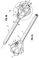
- adapter assembly 200 includes an outer knob housing 202 and an outer tube 206 extending from a distal end of knob housing 202.
- Knob housing 202 and outer tube 206 are configured and dimensioned to house the components of adapter assembly 200.
- Outer tube 206 is dimensioned for endoscopic insertion, in particular, that outer tube is passable through a typical trocar port, cannula or the like.
- Knob housing 202 is dimensioned to not enter the trocar port, cannula of the like.
- Knob housing 202 is configured and adapted to connect to connecting portion 108 of handle housing 102 of surgical device 100.
- Adapter assembly 200 is configured to convert a rotation of either of drive connectors 118 and 120 of surgical device 100 into axial translation useful for operating a drive assembly 360 and an articulation link 366 of loading unit 300, as illustrated in FIG. 48 and as will be described in greater detail below.
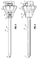
- adapter assembly 200 includes a proximal inner housing assembly 204 rotatably supporting a first rotatable proximal drive shaft 212, a second rotatable proximal drive shaft 214, and a third rotatable proximal drive shaft 216 therein.
- Each proximal drive shaft 212, 214, 216 functions as a rotation receiving member to receive rotational forces from respective drive shafts of surgical device 100, as described in greater detail below.
- inner housing assembly 210 of shaft assembly 200 is also configured to rotatably support first, second and third connector sleeves 218, 220 and 222, respectively, arranged in a common plane or line with one another.
- Each of connector sleeves 218, 220, 222 is configured to mate with respective first, second and third drive connectors 118, 120, 122 of surgical device 100, as described above.
- Each of connector sleeves 218, 220, 222 is further configured to mate with a proximal end of respective first, second and third proximal drive shafts 212, 214, 216.
- Inner housing assembly 210 also includes, as illustrated in FIGS. 6 , 17 , 27 and 28 , a first, a second and a third biasing member 224, 226 and 228 disposed distally of respective first, second and third connector sleeves 218, 220, 222.
- Each of biasing members 224, 226 and 228 is disposed about respective first, second and third rotatable proximal drive shaft 212, 214 and 216.
- Biasing members 224, 226 and 228 act on respective connector sleeves 218, 220 and 222 to help maintain connector sleeves 218, 220 and 222 engaged with the distal end of respective drive rotatable drive connectors 118, 120, 122 of surgical device 100 when adapter assembly 200 is connected to surgical device 100.
- first, second and third biasing members 224, 226 and 228 function to bias respective connector sleeves 218, 220 and 222 in a proximal direction. In this manner, during assembly of adapter assembly 200 to surgical device 100, if first, second and or third connector sleeves 218, 220 and/or 222 is/are misaligned with the drive connectors 118, 120, 122 of surgical device 100, first, second and/or third biasing member(s) 224, 226 and/or 228 are compressed.
- drive connectors 118, 120, 122 of surgical device 100 will rotate and first, second and/or third biasing member(s) 224, 226 and/or 228 will cause respective first, second and/or third connector sleeve(s) 218, 220 and/or 222 to slide back proximally, effectively coupling drive connectors 118, 120, 122 of surgical device 100 to first, second and/or third proximal drive shaft(s) 212, 214 and 216 of inner housing assembly 210.
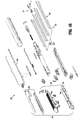
- Adapter assembly 200 includes a plurality of force/rotation transmitting/converting assemblies, each disposed within inner housing assembly 204 and outer tube 206. Each force/rotation transmitting/converting assembly is configured and adapted to transmit/convert a speed/force of rotation (e.g., increase or decrease) of first, second and third rotatable drive connectors 118, 120 and 122 of surgical instrument 100 before transmission of such rotational speed/force to loading unit 300.
- a speed/force of rotation e.g., increase or decrease
- adapter assembly 200 includes a first, a second and a third force/rotation transmitting/converting assembly 240, 250, 260, respectively, disposed within inner housing 208 and outer tube 206.
- Each force/rotation transmitting/converting assembly 240, 250, 260 is configured and adapted to transmit or convert a rotation of a first, second and third drive connector 118, 120, 122 of surgical device 100 into axial translation of articulation bar 258 of adapter assembly 200, to effectuate articulation of loading unit 300; a rotation of a ring gear 266 of adapter assembly 200, to effectuate rotation of adapter assembly 200; or axial translation of a distal drive member 248 of adapter assembly 200 to effectuate closing, opening and firing of loading unit 300.
- first force/rotation transmitting/converting assembly 240 includes first rotatable proximal drive shaft 212, which, as described above, is rotatably supported within inner housing assembly 204.
- First rotatable proximal drive shaft 212 includes a non-circular or shaped proximal end portion configured for connection with first connector 218 which is connected to respective first connector 118 of surgical device 100.
- First rotatable proximal drive shaft 212 includes a distal end portion 212b having a threaded outer profile or surface.
- First force/rotation transmitting/converting assembly 240 further includes a drive coupling nut 244 rotatably coupled to threaded distal end portion 212b of first rotatable proximal drive shaft 212, and which is slidably disposed within outer tube 206.
- Drive coupling nut 244 is slidably keyed within proximal core tube portion of outer tube 206 so as to be prevented from rotation as first rotatable proximal drive shaft 212 is rotated.
- first rotatable proximal drive shaft 212 is rotated, drive coupling nut 244 is translated along threaded distal end portion 212b of first rotatable proximal drive shaft 212 and, in turn, through and/or along outer tube 206.
- First force/rotation transmitting/converting assembly 240 further includes a distal drive member 248 that is mechanically engaged with drive coupling nut 244, such that axial movement of drive coupling nut 244 results in a corresponding amount of axial movement of distal drive member 248.
- the distal end portion of distal drive member 248 supports a connection member 247 configured and dimensioned for selective engagement with a drive member 374 of drive assembly 360 of loading unit 300 ( FIG. 47 ).
- Drive coupling nut 244 and/or distal drive member 248 function as a force transmitting member to components of loading unit 300, as described in greater detail below.
- first rotatable proximal drive shaft 212 is rotated, due to a rotation of first connector sleeve 218, as a result of the rotation of the first respective drive connector 118 of surgical device 100, drive coupling nut 244 is caused to be translated axially along first distal drive shaft 242.
- drive coupling nut 244 is caused to be translated axially along first distal drive shaft 242
- distal drive member 248 is caused to be translated axially relative to outer tube 206.
- distal drive member 248 causes concomitant axial translation of drive member 374 of loading unit 300 to effectuate a closure of tool assembly 304 and a firing of tool assembly 304 of loading unit 300.
- second drive converter assembly 250 of adapter assembly 200 includes second proximal drive shaft 214 rotatably supported within inner housing assembly 204.
- Second rotatable proximal drive shaft 214 includes a non-circular or shaped proximal end portion configured for connection with second connector or coupler 220 which is connected to respective second connector 120 of surgical device 100.
- Second rotatable proximal drive shaft 214 further includes a distal end portion 214b having a threaded outer profile or surface.
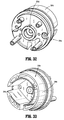
- Articulation bearing assembly 252 includes a housing 252a supporting an articulation bearing 253 having an inner race 253b that is independently rotatable relative to an outer race 253a.
- Articulation bearing housing 252a has a non-circular outer profile, for example tear-dropped shaped, that is slidably and non-rotatably disposed within a complementary bore 204c ( FIGS. 25, 26 , 29 and 33 ) of inner housing hub 204a.
- Second drive converter assembly 250 of adapter assembly 200 further includes an articulation bar 258 having a proximal portion 258a secured to inner race 253b of articulation bearing 253.
- a distal portion 258b of articulation bar 258 includes a slot 258c therein, which is configured to accept a portion 366, e.g., a flag, articulation link ( FIG. 47 ) of loading unit 300.
- Articulation bar 258 functions as a force transmitting member to components of loading unit 300, as described in greater detail below.
- articulation bearing assembly 252 is both rotatable and longitudinally translatable. Additionally, it is envisioned that articulation bearing assembly 252 allows for free, unimpeded rotational movement of loading unit 300 when its jaw members 306, 308 are in an approximated position and/or when jaw members 306, 308 are articulated.
- articulation bearing assembly 252 is caused to be translated axially along threaded distal end portion 214b of second proximal drive shaft 214, which in turn causes articulation bar 258 to be axially translated relative to outer tube 206.
- articulation bar 258 being coupled to articulation link 366 of loading unit 300, causes concomitant axial translation of articulation link 366 of loading unit 300 to effectuate an articulation of tool assembly 304.
- Articulation bar 258 is secured to inner race 253b of articulation bearing 253 and is thus free to rotate about the longitudinal axis X-X relative to outer race 253a of articulation bearing 253.
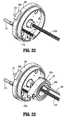
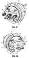
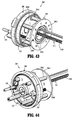
- adapter assembly 200 includes a third force/rotation transmitting/converting assembly 260 supported in inner housing assembly 204.
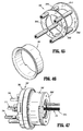
- Third force/rotation transmitting/converting assembly 260 includes a rotation ring gear 266 fixedly supported in and connected to outer knob housing 202.
- Ring gear 266 defines an internal array of gear teeth 266a ( FIG. 6 ).
- Ring gear 266 includes a pair of diametrically opposed, radially extending protrusions 266b ( FIG. 6 ) projecting from an outer edge thereof.
- Protrusions 266b are disposed within recesses defined in outer knob housing 202, such that rotation of ring gear 266 results in rotation of outer knob housing 202, and vice a versa.
- Third force/rotation transmitting/converting assembly 260 further includes third rotatable proximal drive shaft 216 which, as described above, is rotatably supported within inner housing assembly 204.
- Third rotatable proximal drive shaft 216 includes a non-circular or shaped proximal end portion configured for connection with third connector 222 which is connected to respective third connector 122 of surgical device 100.
- Third rotatable proximal drive shaft 216 includes a spur gear 216a keyed to a distal end thereof.
- a reversing spur gear 264 inter-engages spur gear 216a of third rotatable proximal drive shaft 216 to gear teeth 266a of ring gear 266.
- third rotatable proximal drive shaft 216 is rotated, due to a rotation of third connector sleeve 222, as a result of the rotation of the third drive connector 122 of surgical device 100, spur gear 216a of third rotatable proximal drive shaft 216 engages reversing gear 264 causing reversing gear 264 to rotate.
- ring gear 266 also rotates thereby causing outer knob housing 202 to rotate.
- outer knob housing 202 is rotated, outer tube 206 is caused to be rotated about longitudinal axis "X" of adapter assembly 200.
- loading unit 300 that is connected to a distal end portion of adapter assembly 200, is also caused to be rotated about a longitudinal axis of adapter assembly 200.
- Adapter assembly 200 further includes, as seen in FIGS. 1B , 3-5 , 16 , 17 , 20 and 24-26 , an attachment/detachment button 272 supported thereon.
- button 272 is supported on drive coupling assembly 210 of adapter assembly 200 and is biased by a biasing member 274 to an un-actuated condition.
- Button 272 includes lip or ledge 272a formed therewith that is configured to snap behind a corresponding lip or ledge 108b defined along recess 108a of connecting portion 108 of surgical device 100.
- lip 272a of button 272 is disposed behind lip 108b of connecting portion 108 of surgical device 100 to secure and retain adapter assembly 200 and surgical device 100 with one another.
- button 272 is depresses or actuated, against the bias of biasing member 274, to disengage lip 272a of button 272 and lip 108b of connecting portion 108 of surgical device 100.
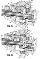
- adapter assembly 200 further includes a lock mechanism 280 for fixing the axial position and radial orientation of distal drive member 248.
- Lock mechanism 280 includes a button 282 slidably supported on outer knob housing 202.
- Lock button 282 is connected to an actuation bar 284 that extends longitudinally through outer tube 206.
- Actuation bar 284 moves upon a movement of lock button 282.
- a distal end of actuation bar 284 may move into contact with a lock out (not shown), which causes the lock out to cam a camming member 288 ( FIG.
- camming member 288 When camming member 288 is in engagement with recess 249 (e.g., at least partially within recess 249, see FIGS. 6 and 24 ), the engagement between camming member 288 and distal drive member 248 effectively locks the axial and rotational position of end effector 300 that is engaged with connection member 247.
- distal drive member 248 In operation, in order to lock the position and/or orientation of distal drive member 248, a user moves lock button 282 from a distal position to a proximal position ( FIGS. 25 and 26 ), thereby causing the lock out (not shown) to move proximally such that a distal face of the lock out moves out of contact with camming member 288, which causes camming member 288 to cam into recess 249 of distal drive member 248. In this manner, distal drive member 248 is prevented from distal and/or proximal movement.
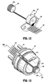
- adapter assembly 200 includes an electrical assembly 290 supported on and in outer knob housing 202 and inner housing assembly 204.
- Electrical assembly 290 includes a plurality of electrical contact pins 292, supported on a circuit board 294, for electrical connection to a corresponding electrical plug 190 disposed in connecting portion 108 of surgical device 100.
- Electrical contacts 290 serve to allow for calibration and communication of life-cycle information to the circuit board of surgical device 100 via electrical plugs 190 that are electrically connected to the circuit board (not shown) of surgical device 100.
- Electrical assembly 290 further includes a strain gauge 296 electrically connected to circuit board 294.
- Strain gauge 296 is provided with a notch 296a which is configured and adapted to receive stem 204d of hub 204a of inner housing assembly 204.
- Stem 204d of hub 204a functions to restrict rotational movement of strain gauge 296.
- first rotatable proximal drive shaft 212 extends through strain gauge 296.
- Strain gauge 296 provides a closed-loop feedback to a firing/clamping load exhibited by first rotatable proximal drive shaft 212.
- Electrical assembly 290 also includes a slip ring 298 disposed core tube of tube 206.
- Slip ring 298 is in electrical connection with circuit board 294.
- Slip ring 298 functions to permit rotation of first rotatable proximal drive shaft 212 and axial translation of drive coupling nut 244 while still maintaining electrical contact of electrical contact rings 298a thereof with at least another electrical component within adapter assembly 200, and while permitting the other electrical components to rotate about first rotatable proximal drive shaft 212 and drive coupling nut 244
- Electrical assembly 290 may include a slip ring cannula or sleeve 299 positioned core tube of tube 206 to protect and/or shield any wires extending from slip ring 298.
- Inner housing assembly 204 has been designed to reduce incidents of racking of second proximal drive shaft 214 as drive shaft 214 rotates to axially translate articulation bearing assembly 252.
- Inner housing assembly 204 includes a hub 204a having a distally oriented annular wall 204b defining a substantially circular outer profile, and defining a substantially tear-drop shaped inner recess or bore 204c. Bore 204c of hub 204a is shaped and dimensioned to slidably receive articulation bearing assembly 252 therewithin.
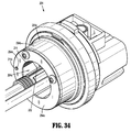
- Inner housing assembly 204 includes a ring plate 254a ( FIG. 34 ) secured to a distal face of distally oriented annular wall 204b of hub 204a.
- Plate 254a defines an aperture 254e therethrough that is sized and formed therein so as to be aligned with second proximal drive shaft 214 and to rotatably receive a distal tip 214c of second proximal drive shaft 214.
- distal tip 214c of second proximal drive shaft 214 is supported and prevented from moving radially away from a longitudinal rotational axis of second proximal drive shaft 214 as second proximal drive shaft 214 is rotated to axially translate articulation bearing assembly 252.
- hub 204a defines a feature (e.g., a stem or the like) 204d projecting therefrom which functions to engage notch 296a of strain gauge 296 of electrical assembly 290 to measure forces experienced by shaft 212 as surgical device 100 is operated.
- a feature e.g., a stem or the like
- Plate bushing 230 of inner housing assembly 204 is shown and described.
- Plate bushing 230 extends across hub 204a of inner housing assembly 204 and is secured to hub 204a by fastening members.
- Plate bushing 230 defines three apertures 230a, 230b, 230c that are aligned with and rotatably receive respective first, second and third proximal drive shafts 212, 214, 216 therein.
- Plate bushing 230 provides a surface against which first, second and third biasing members 224, 226 and 228 come into contact or rest against.
- plate bushing 230 has been shown and described as being a unitary monolithic piece, as illustrated in FIGS. 6 and 37-40 , it is envisioned and within the scope of the present application that plate bushing 230 may be separated into several parts including, and not limited to, as seen in FIGS. 40-42 , a support plate 230'extending across drive shafts 212, 214, 216, and a separate bushing for each of drive shafts 212, 214, 216 and disposed between the support plate 230' and hub 204a of inner housing assembly 204.
- Support plate 230' may include a pair of slots 230a', 230b' formed therein, which are configured and adapted to receive tabs 296b of strain gauge 296 that project axially therefrom.
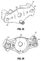
- inner housing assembly 204' may include a reinforcement frame or bracket assembly 254'.
- Bracket assembly 254' includes a first plate 254a' and a second plate 254b' integrally connected to and spaced a distance from first plate 254a' by a plurality of connecting rods 254c' extending therebetween.
- First plate 254a' is disposed adjacent to or in close proximity to ring gear 266 and defines an aperture 254d' therethrough.
- Aperture 254d' is sized and formed in first plate 254a' so as to be aligned with second proximal drive shaft 214 and to permit second proximal drive shaft 214 to freely rotate therewithin.
- Second plate 254b' is spaced from first plate 254a' so as to be disposed at a distal free end of second proximal drive shaft 214.
- Second plate 254b' defines an aperture 254e' therethrough.
- Aperture 254e' is sized and formed in second plate or flange 254b' so as to be aligned with second proximal drive shaft 214 and to rotatably receive a distal tip 214c of second proximal drive shaft 214.
- distal tip 214c of second proximal drive shaft 214 is supported and prevented from moving radially away from a longitudinal rotational axis of second proximal drive shaft 214 as second proximal drive shaft 214 is rotated to axially translate articulation bearing assembly 252.
- inner housing assembly 204' may include a reinforcing sleeve 255' disposed about bracket assembly 254' to further reinforce bracket assembly 254'. It is contemplated in an embodiment that reinforcing sleeve 255' may be interposed between first plate 254a' and second plate 254b' of bracket assembly 254'. It is further contemplated that reinforcing sleeve 255' may be interposed between second plate 254b' and a distally oriented face of proximal inner housing assembly 204'.
- an overall length of adapter assembly 200 has been reduced as compared to prior adapter assemblies that have been developed to transmit/convert forces/rotations from surgical device 100 to loading unit 300.
- a center of gravity of an assembled surgical device 100, adapter assembly 200 and loading unit 300 has been shifted proximally as compared to a center of gravity of an assembled surgical device 100, a prior adapter assembly and a loading unit 300.
- a level of comfort to the end user in using the electromechanical surgical system of the present disclosure has been increased, and a level of fatigue has been decreased.
- the software checks predefined conditions. If conditions are met, the software controls the motors and delivers mechanical drive to the attached surgical stapler, which can then open, close, rotate, articulate or fire depending on the function of the pressed button.
- the software also provides feedback to the user by turning colored lights on or off in a defined manner to indicate the status of surgical device 100, adapter assembly 200 and/or loading unit 300.
- any of the components described herein may be fabricated from either metals, plastics, resins, composites or the like taking into consideration strength, durability, wearability, weight, resistance to corrosion, ease of manufacturing, cost of manufacturing, and the like.
Abstract
Description
- This application claims the benefit of and priority to
U.S. Provisional Patent Application No. 61/913,550, filed December 9, 2013 - The present disclosure relates to adapter assemblies for use in surgical systems. More specifically, the present disclosure relates to adapter assemblies for use with and to electrically and mechanically interconnect electromechanical surgical devices and surgical loading units, and to surgical systems including hand held electromechanical surgical devices and adapter assemblies for connecting surgical loading units to the hand held electromechanical surgical devices.
- A number of surgical device manufacturers have developed product lines with proprietary drive systems for operating and/or manipulating electromechanical surgical devices. In many instances the electromechanical surgical devices include a handle assembly, which is reusable, and disposable loading units and/or single use loading units or the like that are selectively connected to the handle assembly prior to use and then disconnected from the handle assembly following use in order to be disposed of or in some instances sterilized for re-use.
- In certain instances, an adapter assembly is used to interconnect an electromechanical surgical device with any one of a number of surgical loading units to establish a mechanical and/or electrical connection therebetween. By using an adapter assembly to interconnect the electromechanical surgical device with the surgical loading units, an overall length of this electromechanical surgical system tends to be relatively greater/longer as compared to an electromechanical surgical system not using an adapter assembly. This increased length of the electromechanical surgical system (including an adapter assembly) tends to move a center of gravity of the electromechanical surgical system (including an adapter assembly) relatively distal of a center of gravity of another electromechanical surgical system (not including an adapter assembly).
- With the center of gravity being located at a more distal location of the electromechanical surgical system, a torque exerted on the hand, wrist and arm of the user is increased and thus renders use of the electromechanical surgical system tiresome or cumbersome.
- Accordingly, a need exists for an adapter assembly that has a relatively shorter length and that reduces the distal displacement of a center of gravity of the electromechanical surgical system.
- The present disclosure relates to adapter assemblies for use with and to electrically and mechanically interconnect electromechanical surgical devices and surgical loading units, and to surgical systems including hand held electromechanical surgical devices and adapter assemblies for connecting surgical loading units to the hand held electromechanical surgical devices.
- According to an aspect of the present disclosure, an adapter assembly for selectively interconnecting a surgical loading unit that is configured to perform a function and a surgical device that is configured to actuate the loading unit, is provided. The loading unit may include at least one axially translatable drive member, and the surgical device may include at least one rotatable drive shaft. The adapter assembly includes a housing configured and adapted for connection with the surgical device and to be in operative communication with each rotatable drive shaft of the surgical device; an outer tube having a proximal end supported by the housing and a distal end configured and adapted for connection with the loading unit, wherein the distal end of the outer tube is in operative communication with each of the axially translatable drive member of the loading unit; and the force/rotation transmitting/converting assembly for interconnecting a respective one drive shaft of the surgical device and a respective one axially translatable drive member of the loading unit.
- The force/rotation transmitting/converting assembly includes a proximal rotation receiving member that is connectable to a respective rotatable drive shaft of the surgical device; and a distal force transmitting member that is connectable to an axially translatable drive member of the loading unit, the distal force transmitting member being connected to the proximal rotation receiving member in such a manner whereby rotation of the proximal rotation receiving member is converted to axial translation of the distal force transmitting member.
- In operation, the force/rotation transmitting/converting assembly converts and transmits a rotation of the first rotatable drive shaft of the surgical device to an axial translation of the first axially translatable drive member of the loading unit.
- The force/rotation transmitting/converting assembly may include a first force/rotation transmitting/converting assembly. The proximal rotation receiving member of the first force/rotation transmitting/converting assembly may include a first proximal drive shaft defining a threaded distal end. The distal force transmitting member of the first force/rotation transmitting/converting assembly may include a distal drive member threadably connected to the threaded distal end of the first proximal drive shaft.
- The first proximal drive shaft and the distal drive member may be axially aligned with one another and with a rotational axis of the respective rotatable drive shaft of the surgical device.
- In use, rotation of the rotatable drive shaft of the surgical device, associated with the first force/rotation transmitting/converting assembly, may result in rotation of the first rotatable drive shaft of the first force/rotation transmitting/converting assembly which may result in axial translation of the distal drive member of the first force/rotation transmitting/converting assembly.
- The force/rotation transmitting/converting assembly may include a second force/rotation transmitting/converting assembly. The proximal rotation receiving member of the second force/rotation transmitting/converting assembly may include a second proximal drive shaft defining a threaded distal end. The distal force transmitting member of the second force/rotation transmitting/converting assembly may include a bearing assembly having an outer race threadably connected to the threaded distal end of the second proximal drive shaft and being non-rotatably disposed within the housing.
- The bearing assembly may include an inner race. The distal force transmitting member of the second force/rotation transmitting/converting assembly may include an articulation bar having a proximal end secured to the inner race of the bearing assembly, and a distal end configured to selectively engage a second axially translatable drive member of the loading unit.
- At least a portion of the first force/rotation transmitting/converting assembly may extend through the bearing assembly of the second force/rotation transmitting/converting assembly.
- The articulation bar may be rotatable about the first force/rotation transmitting/converting assembly.
- In use, rotation of the rotatable drive shaft of the surgical device, associated with the second force/rotation transmitting/converting assembly, may result in rotation of the second rotatable drive shaft of the second force/rotation transmitting/converting assembly which results in axial translation of the articulation bar of the second force/rotation transmitting/converting assembly.
- The force/rotation transmitting/converting assembly may include a third force/rotation transmitting/converting assembly. The proximal rotation receiving member of the third force/rotation transmitting/converting assembly may include a third proximal drive shaft having a spur gear supported on a distal end thereof. The distal force transmitting member of the third force/rotation transmitting/converting assembly may include a ring gear fixedly supported in the housing and being in gearing connection with the spur gear.
- In use, rotation of the rotatable drive shaft of the surgical device, associated with the third force/rotation transmitting/converting assembly, may result in rotation of the third rotatable drive shaft of the third force/rotation transmitting/converting assembly which results in rotation of the ring gear of the third force/rotation transmitting/converting assembly.
- The adapter assembly may further include an electrical assembly supported within at least one of the housing and the outer tube. The electrical assembly may include a circuit board; and contact pins electrically connected to the circuit board and being configured and adapted to selectively electrically connect to a complementary electrical plug of the surgical device; a strain gauge supported on and electrically connected to the circuit board, wherein the first rotatable proximal drive shaft extends through the strain gauge; and a slip ring disposed about the distal drive member of the first force/rotation transmitting/converting assembly. The slip ring may be in electrical connection with the circuit board, and wherein the slip ring includes electrical contact supported therein for maintaining electrical contact with electrical components within the adapter assembly.
- The first proximal drive shaft, the second proximal drive shaft and the third proximal drive shaft may be arranged in a common plane with one another.
- According to another aspect of the present disclosure, an electromechanical surgical system is provided that is configured for selective connection with a surgical loading unit in order to actuate the loading unit to perform functions. The loading unit may include at least one axially translatable drive member. The surgical system includes a handle-held electromechanical surgical device including a housing; and at least one rotatable drive shaft supported in the projecting from the housing.
- The surgical system further includes an adapter assembly selectively connectable between the housing of the surgical device and the loading unit. The adapter assembly includes a housing configured and adapted for connection with the surgical device and to be in operative communication with each rotatable drive shaft of the surgical device; an outer tube having a proximal end supported by the housing and a distal end configured and adapted for connection with the loading unit, wherein the distal end of the outer tube is in operative communication with each of the axially translatable drive members of the loading unit; and the force/rotation transmitting/converting assemblies for interconnecting a respective drive shafts of the surgical device and the respective axially translatable drive member of the loading unit.
- The force/rotation transmitting/converting assembly includes a proximal rotation receiving member that is connectable to a respective rotatable drive shaft of the surgical device; and a distal force transmitting member that is connectable to an axially translatable drive member of the loading unit, the distal force transmitting member being connected to the proximal rotation receiving member in such a manner whereby rotation of the proximal rotation receiving member is converted to axial translation of the distal force transmitting member.
- The force/rotation transmitting/converting assembly converts and transmits a rotation of the first rotatable drive shaft of the surgical device to an axial translation of the first axially translatable drive member of the loading unit.
- The force/rotation transmitting/converting assembly of the adapter assembly may include a first force/rotation transmitting/converting assembly. The proximal rotation receiving member of the first force/rotation transmitting/converting assembly may include a first proximal drive shaft defining a threaded distal end. The distal force transmitting member of the first force/rotation transmitting/converting assembly may include a distal drive member threadably connected to the threaded distal end of the first proximal drive shaft.
- The first proximal drive shaft and the distal drive member of the adapter assembly may be axially aligned with one another and with a rotational axis of the respective rotatable drive shaft of the surgical device.
- In use, rotation of the rotatable drive shaft of the surgical device, associated with the first force/rotation transmitting/converting assembly, may result in rotation of the first rotatable drive shaft of the first force/rotation transmitting/converting assembly which results in axial translation of the distal drive member of the first force/rotation transmitting/converting assembly of the adapter assembly.
- The force/rotation transmitting/converting assembly of the adapter assembly may include a second force/rotation transmitting/converting assembly. The proximal rotation receiving member of the second force/rotation transmitting/converting assembly may include a second proximal drive shaft defining a threaded distal end. The distal force transmitting member of the second force/rotation transmitting/converting assembly may include a bearing assembly having an outer race threadably connected to the threaded distal end of the second proximal drive shaft and being non-rotatably disposed within the housing.
- The bearing assembly of the adapter assembly may include an inner race, and wherein the distal force transmitting member of the second force/rotation transmitting/converting assembly of the adapter assembly may include an articulation bar having a proximal end secured to the inner race of the bearing assembly, and a distal end configured to selectively engage a second axially translatable drive member of the loading unit.
- At least a portion of the first force/rotation transmitting/converting assembly of the adapter assembly may extend through the bearing assembly of the second force/rotation transmitting/converting assembly of the adapter assembly.
- The articulation bar of the adapter assembly may be rotatable about the first force/rotation transmitting/converting assembly.
- In use, rotation of the rotatable drive shaft of the surgical device, associated with the second force/rotation transmitting/converting assembly of the adapter assembly, may result in rotation of the second rotatable drive shaft of the second force/rotation transmitting/converting assembly which may result in axial translation of the articulation bar of the second force/rotation transmitting/converting assembly.
- The force/rotation transmitting/converting assembly of the adapter assembly may include a third force/rotation transmitting/converting assembly. The proximal rotation receiving member of the third force/rotation transmitting/converting assembly may include a third proximal drive shaft having a spur gear supported on a distal end thereof. The distal force transmitting member of the third force/rotation transmitting/converting assembly may include a ring gear fixedly supported in the housing and being in gearing connection with the spur gear.
- In use, rotation of the rotatable drive shaft of the surgical device, associated with the third force/rotation transmitting/converting assembly, may result in rotation of the third rotatable drive shaft of the third force/rotation transmitting/converting assembly of the adapter assembly which may result in rotation of the ring gear of the third force/rotation transmitting/converting assembly.
- The adapter assembly may further include an electrical assembly supported within at least one of the housing and the outer tube thereof. The electrical assembly may include a circuit board; contact pins electrically connected to the circuit board and being configured and adapted to selectively electrically connect to a complementary electrical plug of the surgical device; a strain gauge supported on and electrically connected to the circuit board, wherein the first rotatable proximal drive shaft extends through the strain gauge; and a slip ring disposed about the distal drive member of the first force/rotation transmitting/converting assembly, wherein the slip ring is in electrical connection with the circuit board, and wherein the slip ring includes electrical contact supported therein for maintaining electrical contact with at least one electrical component within the adapter assembly.
- The first proximal drive shaft, the second proximal drive shaft and the third proximal drive shaft of the adapter assembly may be arranged in a common plane with one another.
- According to a further aspect of the present disclosure, an adapter assembly is provided and includes a housing configured and adapted for connection with the surgical device and to be in operative communication with each rotatable drive shaft of the surgical device; an outer tube having a proximal end supported by the housing and a distal end configured and adapted for connection with the loading unit, wherein the distal end of the outer tube is in operative communication with each of the axially translatable drive member of the loading unit; force/rotation transmitting/converting assembly for interconnecting a respective one drive shaft of the surgical device and a respective one axially translatable drive member of the loading unit; and an electrical assembly supported within the housing and the outer tube thereof.
- The electrical assembly includes a circuit board; contact pins electrically connected to the circuit board and being configured and adapted to selectively electrically connect to a complementary electrical plug of the surgical device; a strain gauge supported on and electrically connected to the circuit board, wherein the first rotatable proximal drive shaft extends through the strain gauge; and a slip ring disposed about at least a portion of the first force/rotation transmitting/converting assembly, wherein the slip ring is in electrical connection with the circuit board, and wherein the slip ring includes electrical contact supported therein for maintaining electrical contact with at least one electrical component within the adapter assembly.
- The force/rotation transmitting/converting assembly may include a proximal rotation receiving member that is connectable to a respective rotatable drive shaft of the surgical device; and a distal force transmitting member that is connectable to an axially translatable drive member of the loading unit, the distal force transmitting member being connected to the proximal rotation receiving member in such a manner whereby rotation of the proximal rotation receiving member is converted to axial translation of the distal force transmitting member.
- In use, the force/rotation transmitting/converting assembly may convert and transmit a rotation of the first rotatable drive shaft of the surgical device to an axial translation of the first axially translatable drive member of the loading unit.
- Embodiments of the present disclosure are described herein with reference to the accompanying drawings, wherein:
-
FIG. 1A is a perspective view of an adapter assembly, in accordance with an embodiment of the present disclosure, interconnected between an exemplary electromechanical surgical device and an end effector assembly; -
FIG. 1B is a perspective view illustrating an attachment of a proximal end of the adapter assembly to a distal end of the electromechanical surgical device; -
FIG. 2A is a front, perspective view of the adapter assembly of the present disclosure; -
FIG. 2B is a rear, perspective view of the adapter assembly ofFIG. 2A ; -
FIG. 3 is a top plan view of the adapter assembly ofFIGS. 2A and 2B ; -
FIG. 4 is a side, elevational view of the adapter assembly ofFIGS. 2A and 2B ; -
FIG. 5 is a rear, perspective view of the adapter assembly ofFIGS. 2A and 2B , with some parts thereof separated; -
FIG. 6 is a rear, perspective view of the adapter assembly ofFIGS. 2A and 2B , with most parts thereof separated; -
FIG. 7 is a perspective view of an articulation assembly of the adapter assembly ofFIGS. 2A and 2B ; -
FIG. 8 is an enlarged, perspective view, with parts separated, of the articulation assembly ofFIG. 7 ; -
FIG. 9 is a perspective view of the articulation assembly ofFIG. 7 , shown in a first orientation; -
FIG. 10 is a perspective view of the articulation assembly ofFIG. 7 , shown in a second orientation; -
FIG. 11 is a cross-sectional view as taken along section line 11-11 ofFIG. 9 ; -
FIG. 12 is a perspective view of an electrical assembly of the adapter assembly ofFIGS. 2A and 2B ; -
FIG. 13 is a perspective view of the electrical assembly ofFIG. 12 shown connected to the core housing of the adapter assembly ofFIGS. 2A and 2B ; -
FIG. 14 is a cross-sectional view as taken along section line 14-14 ofFIG. 13 ; -
FIG. 15 is a perspective view of a slip ring cannula or sleeve of the adapter assembly ofFIGS. 2A and 2B ; -
FIG. 16 is an enlarged view of the indicated area of detail ofFIG. 2B , illustrating an inner housing assembly of the adapter assembly ofFIGS. 2A and 2B ; -
FIG. 17 is a rear, perspective view of the inner housing assembly ofFIG. 16 with an outer knob housing half-section and a proximal cap removed therefrom; -
FIG. 18 is a rear, perspective view of the inner housing assembly ofFIG. 16 with the outer knob housing, the proximal cap and a bushing plate removed therefrom; -
FIG. 19 is a rear, perspective view of the inner housing assembly ofFIG. 16 with the outer knob housing, the proximal cap, the bushing plate and an inner housing removed therefrom; -
FIG. 20 is a rear, perspective view of the an alternative embodiment of inner housing assembly similar to that shown inFIG. 16 with the outer knob housing and the proximal inner housing removed therefrom; -
FIG. 21 is a rear, perspective view of the inner housing assembly ofFIG. 20 with the outer knob housing, the proximal inner housing and the articulation assembly removed therefrom; -
FIG. 22 is a front, perspective view of the inner housing assembly ofFIG. 20 with the outer knob housing, the proximal inner housing and the articulation assembly removed therefrom; -
FIG. 23 is a front, perspective view of the inner housing assembly ofFIG. 20 with the outer knob housing and the proximal inner housing removed therefrom; -
FIG. 24 is a cross-sectional view as taken along section line 24-24 ofFIG. 2B ; -
FIG. 25 is an enlarged view of the indicated area of detail ofFIG. 24 ; -
FIG. 26 is an enlarged view of the indicated area of detail ofFIG. 24 , illustrating a lock button being actuated in a proximal direction; -
FIG. 27 is a cross-sectional view as taken along section line 27-27 ofFIG. 2B ; -
FIG. 28 is a cross-sectional view as taken along section line 27-27 ofFIG. 2B , illustrating actuation of the articulation assembly in a distal direction; -
FIG. 29 is a cross-sectional view as taken along section line 29-29 ofFIG. 28 ; -
FIG. 30 is a cross-sectional view as taken along section line 30-30 ofFIG. 28 ; -
FIG. 31 is a cross-sectional view as taken along section line 31-31 ofFIG. 28 ; -
FIG. 32 is a rear, perspective view of a proximal inner housing hub according to the present disclosure; -
FIG. 33 is a front, perspective view of the proximal inner housing hub ofFIG. 32 ; -
FIG. 34 is a front, perspective view of the proximal inner housing hub ofFIGS. 32 and 33 illustrating a first and a second force/rotation transmitting/converting assembly and a reinforcing assembly associated therewith; -
FIG. 35 is a front, perspective view of a plate bushing of the proximal inner housing assembly of the present disclosure; -
FIG. 36 is a rear, perspective view of the plate bushing ofFIG. 35 ; -
FIG. 37 is a rear, perspective view of the proximal inner housing assembly illustrating the plate bushing ofFIGS. 35 and 36 attached thereto; -
FIG. 38 is a rear, perspective view of the proximal inner housing assembly ofFIG. 37 with connector sleeves removed therefrom; -
FIG. 39 is a rear, perspective view of the proximal inner housing assembly ofFIG. 37 with connector sleeves removed therefrom and the plate bushing shown in phantom; -
FIG. 40 is a rear, perspective view of the proximal inner housing assembly ofFIG. 37 with connector sleeves removed therefrom; -
FIG. 41 is a rear, perspective of the inner housing assembly ofFIG. 37 illustrating a support plate, according to another embodiment of the present disclosure, coupled thereto; -
FIG. 42 is a rear, perspective of the inner housing assembly ofFIG. 41 with the support plate removed therefrom; -
FIG. 43 is a front, perspective view of an inner housing assembly according to another embodiment of the present disclosure with the outer knob housing, the proximal inner housing removed therefrom; -
FIG. 44 is a rear, perspective view of the inner housing assembly ofFIG. 43 with the outer knob housing, the proximal inner housing and the articulation assembly removed therefrom; -
FIG. 45 is a perspective view of a bracket assembly of the inner housing assembly ofFIGS. 43 and 44 ; -
FIG. 46 is a perspective view of a reinforcing sleeve for use with the inner housing assembly ofFIGS. 43 and 44 ; -
FIG. 47 is a perspective view of the inner housing assembly ofFIGS. 43 and 44 , illustrating the reinforcing sleeve ofFIG. 46 supported thereon; and -
FIG. 48 is a perspective view, with parts separated, of an exemplary loading unit for use with the surgical device and the adapter of the present disclosure. - Embodiments of the presently disclosed surgical devices, adapter assemblies, and loading unit detection assemblies for surgical devices and/or handle assemblies are described in detail with reference to the drawings, in which like reference numerals designate identical or corresponding elements in each of the several views. As used herein the term "distal" refers to that portion of the adapter assembly or surgical device, or component thereof, farther from the user, while the term "proximal" refers to that portion of the adapter assembly or surgical device, or component thereof, closer to the user.
- A surgical device, in accordance with an embodiment of the present disclosure, is generally designated as 100, and is in the form of a powered hand held electromechanical instrument configured for selective attachment thereto of a plurality of different end effectors that are each configured for actuation and manipulation by the powered hand held electromechanical surgical instrument.
- As illustrated in
FIG. 1A ,surgical device 100 is configured for selective connection with anadapter assembly 200, and, in turn,adapter assembly 200 is configured for selective connection with a loading unit 300 (e.g., an end effector, multiple- or single-use loading unit, seeFIG. 48 ).Surgical device 100 andadapter assembly 200, together, may comprise an electromechanical surgical system that is configured and adapted to selectively connect with aloading unit 300 and to actuateloading unit 300. - As illustrated in
FIGS. 1A and1B ,surgical device 100 includes ahandle housing 102 including a circuit board (not shown) and a drive mechanism (not shown) is situated therein. The circuit board is configured to control the various operations ofsurgical device 100. Handlehousing 102 defines a cavity therein (not shown) for selective removable receipt of a rechargeable battery (not shown) therein. The battery is configured to supply power to any of the electrical components ofsurgical device 100. - Handle
housing 102 includes anupper housing portion 102a which houses various components ofsurgical device 100, and a lowerhand grip portion 102b extending fromupper housing portion 102a. Lowerhand grip portion 102b may be disposed distally of a proximal-most end ofupper housing portion 102a. The location oflower housing portion 102b relative toupper housing portion 102a is selected to balance a weight of asurgical device 100 that is connected to or supportingadapter assembly 200 and/orend effector 300. - Handle
housing 102 provides a housing in which the drive mechanism is situated. The drive mechanism is configured to drive shafts and/or gear components in order to perform the various operations ofsurgical device 100. In particular, the drive mechanism is configured to drive shafts and/or gear components in order to selectively move atool assembly 304 of loading unit 300 (seeFIGS. 1 and48 ) relative to aproximal body portion 302 ofloading unit 300, to rotateloading unit 300 about a longitudinal axis "X" (seeFIG. 1A ) relative to handlehousing 102, to move/approximate ananvil assembly 306 and acartridge assembly 308 ofloading unit 300 relative to one another, and/or to fire a stapling and cutting cartridge withincartridge assembly 308 ofloading unit 300. - As illustrated in
FIG. 1B , handlehousing 102 defines a connectingportion 108 configured to accept a correspondingdrive coupling assembly 210 ofadapter assembly 200. Specifically, connectingportion 108 ofsurgical device 100 has arecess 108a that receives aproximal cap 210a (FIG. 6 ) ofdrive coupling assembly 210 ofadapter assembly 200 whenadapter assembly 200 is mated tosurgical device 100. Connectingportion 108 houses three rotatable driveconnectors - When
adapter assembly 200 is mated tosurgical device 100, each ofrotatable drive connectors surgical device 100 couples with a correspondingrotatable connector sleeve adapter assembly 200. (seeFIG. 1B ). In this regard, the interface between correspondingfirst drive connector 118 andfirst connector sleeve 218, the interface between correspondingsecond drive connector 120 andsecond connector sleeve 220, and the interface between correspondingthird drive connector 122 andthird connector sleeve 222 are keyed such that rotation of each ofdrive connectors surgical device 100 causes a corresponding rotation of the correspondingconnector sleeve adapter assembly 200. - The mating of
drive connectors surgical device 100 withconnector sleeves adapter assembly 200 allows rotational forces to be independently transmitted via each of the three respective connector interfaces. Thedrive connectors surgical device 100 are configured to be independently rotated by the drive mechanism ofsurgical device 100. In this regard, a function selection module (not shown) of the drive mechanism selects which drive connector orconnectors surgical device 100 is to be driven by the motor ofsurgical device 100. - Since each of
drive connectors surgical device 100 has a keyed and/or substantially non-rotatable interface withrespective connector sleeves adapter assembly 200, whenadapter assembly 200 is coupled tosurgical device 100, rotational force(s) are selectively transferred from drive connectors ofsurgical device 100 toadapter assembly 200. - The selective rotation of drive connector(s) 118, 120 and/or 122 of
surgical device 100 allowssurgical device 100 to selectively actuate different functions ofloading unit 300. For example, selective and independent rotation offirst drive connector 118 ofsurgical device 100 corresponds to the selective and independent opening and closing oftool assembly 304 ofloading unit 300, and driving of a stapling/cutting component oftool assembly 304 ofloading unit 300. As an additional example, the selective and independent rotation ofsecond drive connector 120 ofsurgical device 100 corresponds to the selective and independent articulation oftool assembly 304 ofloading unit 300 transverse to longitudinal axis "X" (seeFIG. 1A ). Additionally, for instance, the selective and independent rotation ofthird drive connector 122 ofsurgical device 100 corresponds to the selective and independent rotation ofloading unit 300 about longitudinal axis "X" (seeFIG. 1A ) relative to handlehousing 102 ofsurgical device 100. - As illustrated in
FIG. 1A , handlehousing 102 supports a plurality of finger-actuated control buttons, rocker devices and the like for activating various functions ofsurgical device 100. - Reference may be made to International Application No.
PCT/US2008/077249, filed September 22, 2008 (Inter. Pub. No.WO 2009/039506 ) andU.S. Patent Application Serial No. 12/622,827, filed on November 20, 2009 surgical instrument 100. - Turning now to
FIGS. 1A-47 ,adapter assembly 200 includes anouter knob housing 202 and anouter tube 206 extending from a distal end ofknob housing 202.Knob housing 202 andouter tube 206 are configured and dimensioned to house the components ofadapter assembly 200.Outer tube 206 is dimensioned for endoscopic insertion, in particular, that outer tube is passable through a typical trocar port, cannula or the like.Knob housing 202 is dimensioned to not enter the trocar port, cannula of the like.Knob housing 202 is configured and adapted to connect to connectingportion 108 ofhandle housing 102 ofsurgical device 100. -
Adapter assembly 200 is configured to convert a rotation of either ofdrive connectors surgical device 100 into axial translation useful for operating adrive assembly 360 and anarticulation link 366 ofloading unit 300, as illustrated inFIG. 48 and as will be described in greater detail below. As illustrated inFIGS. 5 ,6 ,13 ,14 ,17, 18 ,20 ,25-34 and37-40 ,adapter assembly 200 includes a proximalinner housing assembly 204 rotatably supporting a first rotatableproximal drive shaft 212, a second rotatableproximal drive shaft 214, and a third rotatableproximal drive shaft 216 therein. Eachproximal drive shaft surgical device 100, as described in greater detail below. - As described briefly above,
inner housing assembly 210 ofshaft assembly 200 is also configured to rotatably support first, second andthird connector sleeves connector sleeves third drive connectors surgical device 100, as described above. Each ofconnector sleeves proximal drive shafts -
Inner housing assembly 210 also includes, as illustrated inFIGS. 6 ,17 ,27 and 28 , a first, a second and athird biasing member third connector sleeves members proximal drive shaft members respective connector sleeves connector sleeves connectors surgical device 100 whenadapter assembly 200 is connected tosurgical device 100. - In particular, first, second and
third biasing members respective connector sleeves adapter assembly 200 tosurgical device 100, if first, second and orthird connector sleeves drive connectors surgical device 100, first, second and/or third biasing member(s) 224, 226 and/or 228 are compressed. Thus, whensurgical device 100 is operated, driveconnectors surgical device 100 will rotate and first, second and/or third biasing member(s) 224, 226 and/or 228 will cause respective first, second and/or third connector sleeve(s) 218, 220 and/or 222 to slide back proximally, effectively couplingdrive connectors surgical device 100 to first, second and/or third proximal drive shaft(s) 212, 214 and 216 ofinner housing assembly 210. -
Adapter assembly 200 includes a plurality of force/rotation transmitting/converting assemblies, each disposed withininner housing assembly 204 andouter tube 206. Each force/rotation transmitting/converting assembly is configured and adapted to transmit/convert a speed/force of rotation (e.g., increase or decrease) of first, second and thirdrotatable drive connectors surgical instrument 100 before transmission of such rotational speed/force toloading unit 300. - Specifically, as illustrated in
FIG. 6 ,adapter assembly 200 includes a first, a second and a third force/rotation transmitting/convertingassembly outer tube 206. Each force/rotation transmitting/convertingassembly third drive connector surgical device 100 into axial translation ofarticulation bar 258 ofadapter assembly 200, to effectuate articulation ofloading unit 300; a rotation of aring gear 266 ofadapter assembly 200, to effectuate rotation ofadapter assembly 200; or axial translation of adistal drive member 248 ofadapter assembly 200 to effectuate closing, opening and firing ofloading unit 300. - As shown in
FIGS. 5 ,6 and24-31 , first force/rotation transmitting/convertingassembly 240 includes first rotatableproximal drive shaft 212, which, as described above, is rotatably supported withininner housing assembly 204. First rotatableproximal drive shaft 212 includes a non-circular or shaped proximal end portion configured for connection withfirst connector 218 which is connected to respectivefirst connector 118 ofsurgical device 100. First rotatableproximal drive shaft 212 includes adistal end portion 212b having a threaded outer profile or surface. - First force/rotation transmitting/converting
assembly 240 further includes adrive coupling nut 244 rotatably coupled to threadeddistal end portion 212b of first rotatableproximal drive shaft 212, and which is slidably disposed withinouter tube 206. Drivecoupling nut 244 is slidably keyed within proximal core tube portion ofouter tube 206 so as to be prevented from rotation as first rotatableproximal drive shaft 212 is rotated. In this manner, as first rotatableproximal drive shaft 212 is rotated, drivecoupling nut 244 is translated along threadeddistal end portion 212b of first rotatableproximal drive shaft 212 and, in turn, through and/or alongouter tube 206. - First force/rotation transmitting/converting
assembly 240 further includes adistal drive member 248 that is mechanically engaged withdrive coupling nut 244, such that axial movement ofdrive coupling nut 244 results in a corresponding amount of axial movement ofdistal drive member 248. The distal end portion ofdistal drive member 248 supports aconnection member 247 configured and dimensioned for selective engagement with adrive member 374 ofdrive assembly 360 of loading unit 300 (FIG. 47 ). Drivecoupling nut 244 and/ordistal drive member 248 function as a force transmitting member to components ofloading unit 300, as described in greater detail below. - In operation, as first rotatable
proximal drive shaft 212 is rotated, due to a rotation offirst connector sleeve 218, as a result of the rotation of the firstrespective drive connector 118 ofsurgical device 100, drivecoupling nut 244 is caused to be translated axially along first distal drive shaft 242. Asdrive coupling nut 244 is caused to be translated axially along first distal drive shaft 242,distal drive member 248 is caused to be translated axially relative toouter tube 206. Asdistal drive member 248 is translated axially, withconnection member 247 connected thereto and engaged withdrive member 374 ofdrive assembly 360 of loading unit 300 (FIG. 47 ),distal drive member 248 causes concomitant axial translation ofdrive member 374 ofloading unit 300 to effectuate a closure oftool assembly 304 and a firing oftool assembly 304 ofloading unit 300. - With reference to
FIGS. 5-11 ,19 and23-31 , seconddrive converter assembly 250 ofadapter assembly 200 includes secondproximal drive shaft 214 rotatably supported withininner housing assembly 204. Second rotatableproximal drive shaft 214 includes a non-circular or shaped proximal end portion configured for connection with second connector orcoupler 220 which is connected to respectivesecond connector 120 ofsurgical device 100. Second rotatableproximal drive shaft 214 further includes a distal end portion 214b having a threaded outer profile or surface. - Distal end portion 214b of
proximal drive shaft 214 is threadably engaged with anarticulation bearing housing 252a of anarticulation bearing assembly 252.Articulation bearing assembly 252 includes ahousing 252a supporting an articulation bearing 253 having aninner race 253b that is independently rotatable relative to anouter race 253a.Articulation bearing housing 252a has a non-circular outer profile, for example tear-dropped shaped, that is slidably and non-rotatably disposed within acomplementary bore 204c (FIGS. 25, 26 ,29 and33 ) ofinner housing hub 204a. - Second
drive converter assembly 250 ofadapter assembly 200 further includes anarticulation bar 258 having aproximal portion 258a secured toinner race 253b of articulation bearing 253. Adistal portion 258b ofarticulation bar 258 includes aslot 258c therein, which is configured to accept aportion 366, e.g., a flag, articulation link (FIG. 47 ) ofloading unit 300.Articulation bar 258 functions as a force transmitting member to components ofloading unit 300, as described in greater detail below. - With further regard to
articulation bearing assembly 252,articulation bearing assembly 252 is both rotatable and longitudinally translatable. Additionally, it is envisioned thatarticulation bearing assembly 252 allows for free, unimpeded rotational movement ofloading unit 300 when itsjaw members jaw members - In operation, as second
proximal drive shaft 214 is rotated due to a rotation ofsecond connector sleeve 220, as a result of the rotation of thesecond drive connector 120 ofsurgical device 100,articulation bearing assembly 252 is caused to be translated axially along threaded distal end portion 214b of secondproximal drive shaft 214, which in turn causesarticulation bar 258 to be axially translated relative toouter tube 206. Asarticulation bar 258 is translated axially,articulation bar 258, being coupled to articulation link 366 ofloading unit 300, causes concomitant axial translation of articulation link 366 ofloading unit 300 to effectuate an articulation oftool assembly 304.Articulation bar 258 is secured toinner race 253b of articulation bearing 253 and is thus free to rotate about the longitudinal axis X-X relative toouter race 253a of articulation bearing 253. - As illustrated in
FIGS. 6 ,17, 18 ,20-23 ,25-28 ,31 and37-40 and as mentioned above,adapter assembly 200 includes a third force/rotation transmitting/convertingassembly 260 supported ininner housing assembly 204. Third force/rotation transmitting/convertingassembly 260 includes arotation ring gear 266 fixedly supported in and connected toouter knob housing 202.Ring gear 266 defines an internal array ofgear teeth 266a (FIG. 6 ).Ring gear 266 includes a pair of diametrically opposed, radially extendingprotrusions 266b (FIG. 6 ) projecting from an outer edge thereof.Protrusions 266b are disposed within recesses defined inouter knob housing 202, such that rotation ofring gear 266 results in rotation ofouter knob housing 202, and vice a versa. - Third force/rotation transmitting/converting
assembly 260 further includes third rotatableproximal drive shaft 216 which, as described above, is rotatably supported withininner housing assembly 204. Third rotatableproximal drive shaft 216 includes a non-circular or shaped proximal end portion configured for connection withthird connector 222 which is connected to respectivethird connector 122 ofsurgical device 100. Third rotatableproximal drive shaft 216 includes aspur gear 216a keyed to a distal end thereof. A reversingspur gear 264inter-engages spur gear 216a of third rotatableproximal drive shaft 216 to gearteeth 266a ofring gear 266. - In operation, as third rotatable
proximal drive shaft 216 is rotated, due to a rotation ofthird connector sleeve 222, as a result of the rotation of thethird drive connector 122 ofsurgical device 100,spur gear 216a of third rotatableproximal drive shaft 216 engages reversinggear 264 causing reversinggear 264 to rotate. As reversinggear 264 rotates,ring gear 266 also rotates thereby causingouter knob housing 202 to rotate. Asouter knob housing 202 is rotated,outer tube 206 is caused to be rotated about longitudinal axis "X" ofadapter assembly 200. Asouter tube 206 is rotated,loading unit 300, that is connected to a distal end portion ofadapter assembly 200, is also caused to be rotated about a longitudinal axis ofadapter assembly 200. -
Adapter assembly 200 further includes, as seen inFIGS. 1B ,3-5 ,16 ,17 ,20 and24-26 , an attachment/detachment button 272 supported thereon. Specifically,button 272 is supported ondrive coupling assembly 210 ofadapter assembly 200 and is biased by a biasingmember 274 to an un-actuated condition.Button 272 includes lip orledge 272a formed therewith that is configured to snap behind a corresponding lip orledge 108b defined alongrecess 108a of connectingportion 108 ofsurgical device 100. In use, whenadapter assembly 200 is connected tosurgical device 100,lip 272a ofbutton 272 is disposed behindlip 108b of connectingportion 108 ofsurgical device 100 to secure and retainadapter assembly 200 andsurgical device 100 with one another. In order to permit disconnection ofadapter assembly 200 andsurgical device 100 from one another,button 272 is depresses or actuated, against the bias of biasingmember 274, to disengagelip 272a ofbutton 272 andlip 108b of connectingportion 108 ofsurgical device 100. - With reference to
FIGS. 1A ,2A, 2B ,3-5 and24-26 ,adapter assembly 200 further includes alock mechanism 280 for fixing the axial position and radial orientation ofdistal drive member 248.Lock mechanism 280 includes abutton 282 slidably supported onouter knob housing 202.Lock button 282 is connected to anactuation bar 284 that extends longitudinally throughouter tube 206.Actuation bar 284 moves upon a movement oflock button 282. Upon a predetermined amount of movement oflock button 282, a distal end ofactuation bar 284 may move into contact with a lock out (not shown), which causes the lock out to cam a camming member 288 (FIG. 24 ) from arecess 249 indistal drive member 248. When cammingmember 288 is in engagement with recess 249 (e.g., at least partially withinrecess 249, seeFIGS. 6 and24 ), the engagement betweencamming member 288 anddistal drive member 248 effectively locks the axial and rotational position ofend effector 300 that is engaged withconnection member 247. - In operation, in order to lock the position and/or orientation of
distal drive member 248, a user moveslock button 282 from a distal position to a proximal position (FIGS. 25 and 26 ), thereby causing the lock out (not shown) to move proximally such that a distal face of the lock out moves out of contact withcamming member 288, which causescamming member 288 to cam intorecess 249 ofdistal drive member 248. In this manner,distal drive member 248 is prevented from distal and/or proximal movement. Whenlock button 282 is moved from the proximal position to the distal position, the distal end ofactuation bar 284 moves distally into the lock out, against the bias of a biasing member (not shown), to forcecamming member 288 out ofrecess 249, thereby allowing unimpeded axial translation and radial movement ofdistal drive member 248. - Reference may be made to
U.S. Patent Application Serial No. 13/875,571, filed on May 2, 2013 lock mechanism 280. - With reference to
FIGS. 1B ,6 ,12-15 and25-28 ,adapter assembly 200 includes anelectrical assembly 290 supported on and inouter knob housing 202 andinner housing assembly 204.Electrical assembly 290 includes a plurality of electrical contact pins 292, supported on acircuit board 294, for electrical connection to a correspondingelectrical plug 190 disposed in connectingportion 108 ofsurgical device 100.Electrical contacts 290 serve to allow for calibration and communication of life-cycle information to the circuit board ofsurgical device 100 viaelectrical plugs 190 that are electrically connected to the circuit board (not shown) ofsurgical device 100. -
Electrical assembly 290 further includes astrain gauge 296 electrically connected tocircuit board 294.Strain gauge 296 is provided with anotch 296a which is configured and adapted to receivestem 204d ofhub 204a ofinner housing assembly 204.Stem 204d ofhub 204a functions to restrict rotational movement ofstrain gauge 296. As illustrated inFIGS. 25-28 , first rotatableproximal drive shaft 212 extends throughstrain gauge 296.Strain gauge 296 provides a closed-loop feedback to a firing/clamping load exhibited by first rotatableproximal drive shaft 212. -
Electrical assembly 290 also includes aslip ring 298 disposed core tube oftube 206.Slip ring 298 is in electrical connection withcircuit board 294.Slip ring 298 functions to permit rotation of first rotatableproximal drive shaft 212 and axial translation ofdrive coupling nut 244 while still maintaining electrical contact ofelectrical contact rings 298a thereof with at least another electrical component withinadapter assembly 200, and while permitting the other electrical components to rotate about first rotatableproximal drive shaft 212 and drivecoupling nut 244 -
Electrical assembly 290 may include a slip ring cannula orsleeve 299 positioned core tube oftube 206 to protect and/or shield any wires extending fromslip ring 298. - Turning now to
FIGS. 6 ,11 ,14 ,32 and 33 ,inner housing assembly 204 has been designed to reduce incidents of racking of secondproximal drive shaft 214 asdrive shaft 214 rotates to axially translatearticulation bearing assembly 252.Inner housing assembly 204 includes ahub 204a having a distally orientedannular wall 204b defining a substantially circular outer profile, and defining a substantially tear-drop shaped inner recess or bore 204c.Bore 204c ofhub 204a is shaped and dimensioned to slidably receivearticulation bearing assembly 252 therewithin. -
Inner housing assembly 204 includes aring plate 254a (FIG. 34 ) secured to a distal face of distally orientedannular wall 204b ofhub 204a.Plate 254a defines anaperture 254e therethrough that is sized and formed therein so as to be aligned with secondproximal drive shaft 214 and to rotatably receive adistal tip 214c of secondproximal drive shaft 214. In this manner,distal tip 214c of secondproximal drive shaft 214 is supported and prevented from moving radially away from a longitudinal rotational axis of secondproximal drive shaft 214 as secondproximal drive shaft 214 is rotated to axially translatearticulation bearing assembly 252. - As illustrated in
FIGS. 14 ,32 ,39 and 40 ,hub 204a defines a feature (e.g., a stem or the like) 204d projecting therefrom which functions to engagenotch 296a ofstrain gauge 296 ofelectrical assembly 290 to measure forces experienced byshaft 212 assurgical device 100 is operated. - With reference to
FIGS. 35-40 , aplate bushing 230 ofinner housing assembly 204 is shown and described.Plate bushing 230 extends acrosshub 204a ofinner housing assembly 204 and is secured tohub 204a by fastening members.Plate bushing 230 defines threeapertures proximal drive shafts Plate bushing 230 provides a surface against which first, second andthird biasing members - While
plate bushing 230 has been shown and described as being a unitary monolithic piece, as illustrated inFIGS. 6 and37-40 , it is envisioned and within the scope of the present application thatplate bushing 230 may be separated into several parts including, and not limited to, as seen inFIGS. 40-42 , a support plate 230'extending acrossdrive shafts drive shafts hub 204a ofinner housing assembly 204. Support plate 230' may include a pair ofslots 230a', 230b' formed therein, which are configured and adapted to receivetabs 296b ofstrain gauge 296 that project axially therefrom. - Turning now to
FIGS. 43-47 , an inner housing assembly 204' according to another embodiment of the present disclosure is shown and will be described. In order to reduce incidents of racking (i.e., distal end 214b of secondproximal drive shaft 214 moving radially away from a longitudinal rotational axis thereof) of secondproximal drive shaft 214 asdrive shaft 214 rotates to axially translatearticulation bearing assembly 252, inner housing assembly 204' may include a reinforcement frame or bracket assembly 254'. Bracket assembly 254' includes afirst plate 254a' and asecond plate 254b' integrally connected to and spaced a distance fromfirst plate 254a' by a plurality of connectingrods 254c' extending therebetween. -
First plate 254a' is disposed adjacent to or in close proximity to ringgear 266 and defines anaperture 254d' therethrough.Aperture 254d' is sized and formed infirst plate 254a' so as to be aligned with secondproximal drive shaft 214 and to permit secondproximal drive shaft 214 to freely rotate therewithin.Second plate 254b' is spaced fromfirst plate 254a' so as to be disposed at a distal free end of secondproximal drive shaft 214.Second plate 254b' defines anaperture 254e' therethrough.Aperture 254e' is sized and formed in second plate orflange 254b' so as to be aligned with secondproximal drive shaft 214 and to rotatably receive adistal tip 214c of secondproximal drive shaft 214. - In this manner,
distal tip 214c of secondproximal drive shaft 214 is supported and prevented from moving radially away from a longitudinal rotational axis of secondproximal drive shaft 214 as secondproximal drive shaft 214 is rotated to axially translatearticulation bearing assembly 252. - As illustrated in
FIGS. 38 ,46 and 47 , inner housing assembly 204' may include a reinforcing sleeve 255' disposed about bracket assembly 254' to further reinforce bracket assembly 254'. It is contemplated in an embodiment that reinforcing sleeve 255' may be interposed betweenfirst plate 254a' andsecond plate 254b' of bracket assembly 254'. It is further contemplated that reinforcing sleeve 255' may be interposed betweensecond plate 254b' and a distally oriented face of proximal inner housing assembly 204'. - In accordance with the present disclosure, an overall length of
adapter assembly 200 has been reduced as compared to prior adapter assemblies that have been developed to transmit/convert forces/rotations fromsurgical device 100 toloading unit 300. By reducing an overall length ofadapter assembly 200, a center of gravity of an assembledsurgical device 100,adapter assembly 200 andloading unit 300 has been shifted proximally as compared to a center of gravity of an assembledsurgical device 100, a prior adapter assembly and aloading unit 300. As such, a level of comfort to the end user in using the electromechanical surgical system of the present disclosure has been increased, and a level of fatigue has been decreased. - In operation, when a button of
surgical device 100 is activated by the user, the software checks predefined conditions. If conditions are met, the software controls the motors and delivers mechanical drive to the attached surgical stapler, which can then open, close, rotate, articulate or fire depending on the function of the pressed button. The software also provides feedback to the user by turning colored lights on or off in a defined manner to indicate the status ofsurgical device 100,adapter assembly 200 and/orloading unit 300. - Reference may be made to
U.S. Patent Publication No. 2009/0314821, filed on August 31, 2009 , entitled "TOOL ASSEMBLY FOR A SURGICAL STAPLING DEVICE" for a detailed discussion of the construction and operation ofloading unit 300, as illustrated inFIGS. 1 and48 . - Any of the components described herein may be fabricated from either metals, plastics, resins, composites or the like taking into consideration strength, durability, wearability, weight, resistance to corrosion, ease of manufacturing, cost of manufacturing, and the like.
- It will be understood that various modifications may be made to the embodiments of the presently disclosed adapter assemblies. Therefore, the above description should not be construed as limiting, but merely as exemplifications of embodiments. Those skilled in the art will envision other modifications within the scope and spirit of the present disclosure.
- The invention may be described by reference to the following numbered paragraphs:-
- 1. An adapter assembly for selectively interconnecting a surgical loading unit that is configured to perform a function and a surgical device that is configured to actuate the loading unit, the loading unit including an axially translatable drive member, and the surgical device including a rotatable drive shaft, the adapter assembly comprising:
- a housing configured and adapted for connection with the surgical device and to be in operative communication with each rotatable drive shaft of the surgical device;
- an outer tube having a proximal end supported by the housing and a distal end configured and adapted for connection with the loading unit, wherein the distal end of the outer tube is in operative communication with each of the at least one axially translatable drive member of the loading unit; and
- at least one force/rotation transmitting/converting assembly for interconnecting a respective one drive shaft of the surgical device and a respective one axially translatable drive member of the loading unit, wherein the at least one force/rotation transmitting/converting assembly includes:
- a proximal rotation receiving member that is connectable to a respective rotatable drive shaft of the surgical device; and
- a distal force transmitting member that is connectable to an axially translatable drive member of the loading unit, the distal force transmitting member being connected to the proximal rotation receiving member in such a manner whereby rotation of the proximal rotation receiving member is converted to axial translation of the distal force transmitting member;
- wherein the at least one force/rotation transmitting/converting assembly converts and transmits a rotation of the first rotatable drive shaft of the surgical device to an axial translation of the first axially translatable drive member of the loading unit.
- 2. The adapter assembly according to
paragraph 1, wherein the at least one force/rotation transmitting/converting assembly includes a first force/rotation transmitting/converting assembly; wherein the proximal rotation receiving member of the first force/rotation transmitting/converting assembly includes a first proximal drive shaft defining a threaded distal end; and wherein the distal force transmitting member of the first force/rotation transmitting/converting assembly includes a distal drive member threadably connected to the threaded distal end of the first proximal drive shaft. - 3. The adapter assembly according to paragraph 2, wherein the first proximal drive shaft and the distal drive member are axially aligned with one another and with a rotational axis of the respective rotatable drive shaft of the surgical device.
- 4. The adapter assembly according to paragraph 2, wherein rotation of the rotatable drive shaft of the surgical device, associated with the first force/rotation transmitting/converting assembly, results in rotation of the first rotatable drive shaft of the first force/rotation transmitting/converting assembly which results in axial translation of the distal drive member of the first force/rotation transmitting/converting assembly.
- 5. The adapter assembly according to paragraph 2, wherein the at least one force/rotation transmitting/converting assembly includes a second force/rotation transmitting/converting assembly; wherein the proximal rotation receiving member of the second force/rotation transmitting/converting assembly includes a second proximal drive shaft defining a threaded distal end; and wherein the distal force transmitting member of the second force/rotation transmitting/converting assembly includes a bearing assembly having an outer race threadably connected to the threaded distal end of the second proximal drive shaft and being non-rotatably disposed within the housing.
- 6. The adapter assembly according to paragraph 5, wherein the bearing assembly includes an inner race, and wherein the distal force transmitting member of the second force/rotation transmitting/converting assembly includes an articulation bar having a proximal end secured to the inner race of the bearing assembly, and a distal end configured to selectively engage a second axially translatable drive member of the loading unit.
- 7. The adapter assembly according to paragraph 5, wherein at least a portion of the first force/rotation transmitting/converting assembly extends through the bearing assembly of the second force/rotation transmitting/converting assembly.
- 8. The adapter assembly according to paragraph 7, wherein the articulation bar is rotatable about the first force/rotation transmitting/converting assembly.
- 9. The adapter assembly according to paragraph 5, wherein rotation of the rotatable drive shaft of the surgical device, associated with the second force/rotation transmitting/converting assembly, results in rotation of the second rotatable drive shaft of the second force/rotation transmitting/converting assembly which results in axial translation of the articulation bar of the second force/rotation transmitting/converting assembly.
- 10. The adapter assembly according to paragraph 9, wherein the at least one force/rotation transmitting/converting assembly includes a third force/rotation transmitting/converting assembly; wherein the proximal rotation receiving member of the third force/rotation transmitting/converting assembly includes a third proximal drive shaft having a spur gear supported on a distal end thereof; and wherein the distal force transmitting member of the third force/rotation transmitting/converting assembly includes a ring gear fixedly supported in the housing and being in gearing connection with the spur gear.
- 11. The adapter assembly according to paragraph 10, wherein rotation of the rotatable drive shaft of the surgical device, associated with the third force/rotation transmitting/converting assembly, results in rotation of the third rotatable drive shaft of the third force/rotation transmitting/converting assembly which results in rotation of the ring gear of the third force/rotation transmitting/converting assembly.
- 12. The adapter assembly according to paragraph 10, further comprising an electrical assembly supported within at least one of the housing and the outer tube, the electrical assembly including:
- a circuit board;
- at least one contact pin electrically connected to the circuit board and being configured and adapted to selectively electrically connect to a complementary electrical plug of the surgical device;
- a strain gauge supported on and electrically connected to the circuit board, wherein the first rotatable proximal drive shaft extends through the strain gauge; and
- a slip ring disposed about the distal drive member of the first force/rotation transmitting/converting assembly, wherein the slip ring is in electrical connection with the circuit board, and wherein the slip ring includes electrical contact supported therein for maintaining electrical contact with at least one electrical component within the adapter assembly.
- 13. The adapter assembly according to paragraph 10, wherein the first proximal drive shaft, the second proximal drive shaft and the third proximal drive shaft are arranged in a common plane with one another.
Claims (13)
- An adapter assembly for selectively interconnecting a surgical loading unit that is configured to perform a function and a surgical device that is configured to actuate the loading unit, the loading unit including an axially translatable drive member, and the surgical device including a rotatable drive shaft, the adapter assembly comprising:a housing configured and adapted for connection with the surgical device and to be in operative communication with each rotatable drive shaft of the surgical device;an outer tube having a proximal end supported by the housing and a distal end configured and adapted for connection with the loading unit, wherein the distal end of the outer tube is in operative communication with each of the at least one axially translatable drive member of the loading unit; andat least one force/rotation transmitting/converting assembly for interconnecting a respective one drive shaft of the surgical device and a respective one axially translatable drive member of the loading unit, wherein the at least one force/rotation transmitting/converting assembly includes:a proximal rotation receiving member that is connectable to a respective rotatable drive shaft of the surgical device; anda distal force transmitting member that is connectable to an axially translatable drive member of the loading unit, the distal force transmitting member being connected to the proximal rotation receiving member in such a manner whereby rotation of the proximal rotation receiving member is converted to axial translation of the distal force transmitting member;wherein the at least one force/rotation transmitting/converting assembly converts and transmits a rotation of the first rotatable drive shaft of the surgical device to an axial translation of the first axially translatable drive member of the loading unit.
- The adapter assembly according to claim 1, wherein the at least one force/rotation transmitting/converting assembly includes a first force/rotation transmitting/converting assembly; wherein the proximal rotation receiving member of the first force/rotation transmitting/converting assembly includes a first proximal drive shaft defining a threaded distal end; and wherein the distal force transmitting member of the first force/rotation transmitting/converting assembly includes a distal drive member threadably connected to the threaded distal end of the first proximal drive shaft.
- The adapter assembly according to claim 2, wherein the first proximal drive shaft and the distal drive member are axially aligned with one another and with a rotational axis of the respective rotatable drive shaft of the surgical device.
- The adapter assembly according to claim 2 or claim 3, wherein rotation of the rotatable drive shaft of the surgical device, associated with the first force/rotation transmitting/converting assembly, results in rotation of the first rotatable drive shaft of the first force/rotation transmitting/converting assembly which results in axial translation of the distal drive member of the first force/rotation transmitting/converting assembly.
- The adapter assembly according to any of claims 2 to 4, wherein the at least one force/rotation transmitting/converting assembly includes a second force/rotation transmitting/converting assembly; wherein the proximal rotation receiving member of the second force/rotation transmitting/converting assembly includes a second proximal drive shaft defining a threaded distal end; and wherein the distal force transmitting member of the second force/rotation transmitting/converting assembly includes a bearing assembly having an outer race threadably connected to the threaded distal end of the second proximal drive shaft and being non-rotatably disposed within the housing.
- The adapter assembly according to claim 5, wherein the bearing assembly includes an inner race, and wherein the distal force transmitting member of the second force/rotation transmitting/converting assembly includes an articulation bar having a proximal end secured to the inner race of the bearing assembly, and a distal end configured to selectively engage a second axially translatable drive member of the loading unit.
- The adapter assembly according to claim 5 or claim 6, wherein at least a portion of the first force/rotation transmitting/converting assembly extends through the bearing assembly of the second force/rotation transmitting/converting assembly.
- The adapter assembly according to claim 7, wherein the articulation bar is rotatable about the first force/rotation transmitting/converting assembly.
- The adapter assembly according to claim 5, wherein rotation of the rotatable drive shaft of the surgical device, associated with the second force/rotation transmitting/converting assembly, results in rotation of the second rotatable drive shaft of the second force/rotation transmitting/converting assembly which results in axial translation of the articulation bar of the second force/rotation transmitting/converting assembly.
- The adapter assembly according to claim 9, wherein the at least one force/rotation transmitting/converting assembly includes a third force/rotation transmitting/converting assembly; wherein the proximal rotation receiving member of the third force/rotation transmitting/converting assembly includes a third proximal drive shaft having a spur gear supported on a distal end thereof; and wherein the distal force transmitting member of the third force/rotation transmitting/converting assembly includes a ring gear fixedly supported in the housing and being in gearing connection with the spur gear.
- The adapter assembly according to claim 10, wherein rotation of the rotatable drive shaft of the surgical device, associated with the third force/rotation transmitting/converting assembly, results in rotation of the third rotatable drive shaft of the third force/rotation transmitting/converting assembly which results in rotation of the ring gear of the third force/rotation transmitting/converting assembly.
- The adapter assembly according to any preceding claim, further comprising an electrical assembly supported within at least one of the housing and the outer tube, the electrical assembly including:a circuit board;at least one contact pin electrically connected to the circuit board and being configured and adapted to selectively electrically connect to a complementary electrical plug of the surgical device;a strain gauge supported on and electrically connected to the circuit board, wherein the first rotatable proximal drive shaft extends through the strain gauge; anda slip ring disposed about the distal drive member of the first force/rotation transmitting/converting assembly, wherein the slip ring is in electrical connection with the circuit board, and wherein the slip ring includes electrical contact supported therein for maintaining electrical contact with at least one electrical component within the adapter assembly.
- The adapter assembly according to any of claims 10 to 12 wherein the first proximal drive shaft, the second proximal drive shaft and the third proximal drive shaft are arranged in a common plane with one another.
Priority Applications (2)
| Application Number | Priority Date | Filing Date | Title |
|---|---|---|---|
| EP19192890.2A EP3597124A1 (en) | 2013-12-09 | 2014-12-08 | Adapter assembly for interconnecting electromechanical surgical devices and surgical loading units, and surgical systems thereof |
| EP17171082.5A EP3238640B1 (en) | 2013-12-09 | 2014-12-08 | Adapter assembly for interconnecting electromechanical surgical devices and surgical loading units, and surgical systems thereof |
Applications Claiming Priority (4)
| Application Number | Priority Date | Filing Date | Title |
|---|---|---|---|
| US201361913572P | 2013-12-09 | 2013-12-09 | |
| US201361913550P | 2013-12-09 | 2013-12-09 | |
| US14/550,071 US9918713B2 (en) | 2013-12-09 | 2014-11-21 | Adapter assembly for interconnecting electromechanical surgical devices and surgical loading units, and surgical systems thereof |
| US14/550,183 US10561417B2 (en) | 2013-12-09 | 2014-11-21 | Adapter assembly for interconnecting electromechanical surgical devices and surgical loading units, and surgical systems thereof |
Related Child Applications (3)
| Application Number | Title | Priority Date | Filing Date |
|---|---|---|---|
| EP17171082.5A Division-Into EP3238640B1 (en) | 2013-12-09 | 2014-12-08 | Adapter assembly for interconnecting electromechanical surgical devices and surgical loading units, and surgical systems thereof |
| EP17171082.5A Division EP3238640B1 (en) | 2013-12-09 | 2014-12-08 | Adapter assembly for interconnecting electromechanical surgical devices and surgical loading units, and surgical systems thereof |
| EP19192890.2A Division EP3597124A1 (en) | 2013-12-09 | 2014-12-08 | Adapter assembly for interconnecting electromechanical surgical devices and surgical loading units, and surgical systems thereof |
Publications (3)
| Publication Number | Publication Date |
|---|---|
| EP2881046A2 true EP2881046A2 (en) | 2015-06-10 |
| EP2881046A3 EP2881046A3 (en) | 2015-08-26 |
| EP2881046B1 EP2881046B1 (en) | 2017-07-05 |
Family
ID=55177662
Family Applications (5)
| Application Number | Title | Priority Date | Filing Date |
|---|---|---|---|
| EP19192890.2A Withdrawn EP3597124A1 (en) | 2013-12-09 | 2014-12-08 | Adapter assembly for interconnecting electromechanical surgical devices and surgical loading units, and surgical systems thereof |
| EP14196704.2A Active EP2889009B1 (en) | 2013-12-09 | 2014-12-08 | Adapter assembly for interconnecting electromechanical surgical devices and surgical loading units, and surgical systems thereof |
| EP17162427.3A Active EP3210545B1 (en) | 2013-12-09 | 2014-12-08 | Adapter assembly for interconnecting electromechanical surgical devices and surgical loading units, and surgical systems thereof |
| EP14196833.9A Active EP2881046B1 (en) | 2013-12-09 | 2014-12-08 | Adapter assembly for interconnecting electromechanical surgical devices and surgical loading units, and surgical systems thereof |
| EP17171082.5A Active EP3238640B1 (en) | 2013-12-09 | 2014-12-08 | Adapter assembly for interconnecting electromechanical surgical devices and surgical loading units, and surgical systems thereof |
Family Applications Before (3)
| Application Number | Title | Priority Date | Filing Date |
|---|---|---|---|
| EP19192890.2A Withdrawn EP3597124A1 (en) | 2013-12-09 | 2014-12-08 | Adapter assembly for interconnecting electromechanical surgical devices and surgical loading units, and surgical systems thereof |
| EP14196704.2A Active EP2889009B1 (en) | 2013-12-09 | 2014-12-08 | Adapter assembly for interconnecting electromechanical surgical devices and surgical loading units, and surgical systems thereof |
| EP17162427.3A Active EP3210545B1 (en) | 2013-12-09 | 2014-12-08 | Adapter assembly for interconnecting electromechanical surgical devices and surgical loading units, and surgical systems thereof |
Family Applications After (1)
| Application Number | Title | Priority Date | Filing Date |
|---|---|---|---|
| EP17171082.5A Active EP3238640B1 (en) | 2013-12-09 | 2014-12-08 | Adapter assembly for interconnecting electromechanical surgical devices and surgical loading units, and surgical systems thereof |
Country Status (7)
| Country | Link |
|---|---|
| US (4) | US10561417B2 (en) |
| EP (5) | EP3597124A1 (en) |
| JP (2) | JP6484018B2 (en) |
| CN (4) | CN104688348B (en) |
| AU (5) | AU2014268210B2 (en) |
| CA (2) | CA2872517A1 (en) |
| ES (2) | ES2635259T3 (en) |
Cited By (31)
| Publication number | Priority date | Publication date | Assignee | Title |
|---|---|---|---|---|
| EP2959841A1 (en) * | 2014-06-26 | 2015-12-30 | Covidien LP | Adapter assembly for interconnecting electromechanical surgical devices and surgical loading units, and surgical systems thereof |
| EP2959842A1 (en) * | 2014-06-26 | 2015-12-30 | Covidien LP | Adapter assemblies for interconnecting electromechanical handle assemblies and surgical loading units |
| EP2959839A1 (en) * | 2014-06-26 | 2015-12-30 | Covidien LP | Adapter assembly for interconnecting electromechanical surgical devices and surgical loading units, and surgical systems thereof |
| CN106419984A (en) * | 2015-08-11 | 2017-02-22 | 柯惠Lp公司 | Adapter assembly for interconnecting electromechanical surgical devices and surgical loading units, and surgical systems thereof |
| EP3173031A1 (en) * | 2015-11-24 | 2017-05-31 | Covidien LP | Adapter assembly for interconnecting electromechanical surgical devices |
| WO2018039606A1 (en) | 2016-08-25 | 2018-03-01 | Virtual Incision Corporation | Quick-release tool coupler and related systems and methods |
| US9918713B2 (en) | 2013-12-09 | 2018-03-20 | Covidien Lp | Adapter assembly for interconnecting electromechanical surgical devices and surgical loading units, and surgical systems thereof |
| EP2621367B1 (en) * | 2010-09-30 | 2018-09-05 | Ethicon LLC | Compressible fastener cartridge |
| EP3178413B1 (en) * | 2015-12-10 | 2019-06-26 | Covidien LP | Handheld electromechanical surgical instruments |
| US10772631B2 (en) | 2013-12-09 | 2020-09-15 | Covidien Lp | Adapter assembly for interconnecting electromechanical surgical devices and surgical loading units, and surgical systems thereof |
| US11051895B2 (en) | 2012-08-08 | 2021-07-06 | Board Of Regents Of The University Of Nebraska | Robotic surgical devices, systems, and related methods |
| US11058429B2 (en) | 2019-06-24 | 2021-07-13 | Covidien Lp | Load sensing assemblies and methods of manufacturing load sensing assemblies |
| US11076850B2 (en) | 2019-11-26 | 2021-08-03 | Covidien Lp | Surgical instrument including an adapter assembly and an articulating surgical loading unit |
| US11284958B2 (en) | 2016-11-29 | 2022-03-29 | Virtual Incision Corporation | User controller with user presence detection and related systems and methods |
| US11291446B2 (en) | 2019-12-18 | 2022-04-05 | Covidien Lp | Surgical instrument including an adapter assembly and an articulating surgical loading unit |
| US11504196B2 (en) | 2018-01-05 | 2022-11-22 | Board Of Regents Of The University Of Nebraska | Single-arm robotic device with compact joint design and related systems and methods |
| US11595242B2 (en) | 2011-07-11 | 2023-02-28 | Board Of Regents Of The University Of Nebraska | Robotic surgical devices, systems and related methods |
| US11633253B2 (en) | 2013-03-15 | 2023-04-25 | Virtual Incision Corporation | Robotic surgical devices, systems, and related methods |
| US11786334B2 (en) | 2016-12-14 | 2023-10-17 | Virtual Incision Corporation | Releasable attachment device for coupling to medical devices and related systems and methods |
| US11806097B2 (en) | 2013-03-14 | 2023-11-07 | Board Of Regents Of The University Of Nebraska | Methods, systems, and devices relating to robotic surgical devices, end effectors, and controllers |
| US11819299B2 (en) | 2012-05-01 | 2023-11-21 | Board Of Regents Of The University Of Nebraska | Single site robotic device and related systems and methods |
| US11819209B2 (en) | 2021-08-03 | 2023-11-21 | Covidien Lp | Hand-held surgical instruments |
| US11826014B2 (en) | 2016-05-18 | 2023-11-28 | Virtual Incision Corporation | Robotic surgical devices, systems and related methods |
| US11826032B2 (en) | 2013-07-17 | 2023-11-28 | Virtual Incision Corporation | Robotic surgical devices, systems and related methods |
| US11832902B2 (en) | 2012-08-08 | 2023-12-05 | Virtual Incision Corporation | Robotic surgical devices, systems, and related methods |
| US11832871B2 (en) | 2011-06-10 | 2023-12-05 | Board Of Regents Of The University Of Nebraska | Methods, systems, and devices relating to surgical end effectors |
| US11862884B2 (en) | 2021-08-16 | 2024-01-02 | Covidien Lp | Surgical instrument with electrical connection |
| US11872090B2 (en) | 2015-08-03 | 2024-01-16 | Virtual Incision Corporation | Robotic surgical devices, systems, and related methods |
| US11883065B2 (en) | 2012-01-10 | 2024-01-30 | Board Of Regents Of The University Of Nebraska | Methods, systems, and devices for surgical access and insertion |
| US11903658B2 (en) | 2019-01-07 | 2024-02-20 | Virtual Incision Corporation | Robotically assisted surgical system and related devices and methods |
| US11950867B2 (en) | 2022-11-04 | 2024-04-09 | Board Of Regents Of The University Of Nebraska | Single-arm robotic device with compact joint design and related systems and methods |
Families Citing this family (314)
| Publication number | Priority date | Publication date | Assignee | Title |
|---|---|---|---|---|
| US10285694B2 (en) | 2001-10-20 | 2019-05-14 | Covidien Lp | Surgical stapler with timer and feedback display |
| US11311291B2 (en) | 2003-10-17 | 2022-04-26 | Covidien Lp | Surgical adapter assemblies for use between surgical handle assembly and surgical end effectors |
| US10022123B2 (en) | 2012-07-09 | 2018-07-17 | Covidien Lp | Surgical adapter assemblies for use between surgical handle assembly and surgical end effectors |
| US10105140B2 (en) | 2009-11-20 | 2018-10-23 | Covidien Lp | Surgical console and hand-held surgical device |
| US9055943B2 (en) | 2007-09-21 | 2015-06-16 | Covidien Lp | Hand held surgical handle assembly, surgical adapters for use between surgical handle assembly and surgical end effectors, and methods of use |
| WO2006015319A2 (en) | 2004-07-30 | 2006-02-09 | Power Medical Interventions, Inc. | Flexible shaft extender and method of using same |
| US7845536B2 (en) | 2004-10-18 | 2010-12-07 | Tyco Healthcare Group Lp | Annular adhesive structure |
| US7938307B2 (en) | 2004-10-18 | 2011-05-10 | Tyco Healthcare Group Lp | Support structures and methods of using the same |
| US11291443B2 (en) | 2005-06-03 | 2022-04-05 | Covidien Lp | Surgical stapler with timer and feedback display |
| CN102988087B (en) | 2005-07-27 | 2015-09-09 | 柯惠Lp公司 | Such as the axle of electro-mechanical surgical device |
| US7665646B2 (en) | 2007-06-18 | 2010-02-23 | Tyco Healthcare Group Lp | Interlocking buttress material retention system |
| WO2009039510A1 (en) | 2007-09-21 | 2009-03-26 | Power Medical Interventions, Inc. | Surgical device |
| US8517241B2 (en) | 2010-04-16 | 2013-08-27 | Covidien Lp | Hand-held surgical devices |
| US10779818B2 (en) | 2007-10-05 | 2020-09-22 | Covidien Lp | Powered surgical stapling device |
| US10498269B2 (en) | 2007-10-05 | 2019-12-03 | Covidien Lp | Powered surgical stapling device |
| US9486215B2 (en) | 2009-03-31 | 2016-11-08 | Covidien Lp | Surgical stapling apparatus |
| US8292150B2 (en) | 2010-11-02 | 2012-10-23 | Tyco Healthcare Group Lp | Adapter for powered surgical devices |
| US9549758B2 (en) | 2011-03-23 | 2017-01-24 | Covidien Lp | Surgical access assembly with adapter |
| US11207089B2 (en) | 2011-10-25 | 2021-12-28 | Covidien Lp | Apparatus for endoscopic procedures |
| US9480492B2 (en) | 2011-10-25 | 2016-11-01 | Covidien Lp | Apparatus for endoscopic procedures |
| US9492146B2 (en) | 2011-10-25 | 2016-11-15 | Covidien Lp | Apparatus for endoscopic procedures |
| US9364231B2 (en) | 2011-10-27 | 2016-06-14 | Covidien Lp | System and method of using simulation reload to optimize staple formation |
| US9237892B2 (en) | 2011-12-14 | 2016-01-19 | Covidien Lp | Buttress attachment to the cartridge surface |
| US9326773B2 (en) | 2012-01-26 | 2016-05-03 | Covidien Lp | Surgical device including buttress material |
| US9597104B2 (en) | 2012-06-01 | 2017-03-21 | Covidien Lp | Handheld surgical handle assembly, surgical adapters for use between surgical handle assembly and surgical end effectors, and methods of use |
| US9868198B2 (en) | 2012-06-01 | 2018-01-16 | Covidien Lp | Hand held surgical handle assembly, surgical adapters for use between surgical handle assembly and surgical loading units, and methods of use |
| US10080563B2 (en) | 2012-06-01 | 2018-09-25 | Covidien Lp | Loading unit detection assembly and surgical device for use therewith |
| US10492814B2 (en) | 2012-07-09 | 2019-12-03 | Covidien Lp | Apparatus for endoscopic procedures |
| US9839480B2 (en) | 2012-07-09 | 2017-12-12 | Covidien Lp | Surgical adapter assemblies for use between surgical handle assembly and surgical end effectors |
| US9421014B2 (en) | 2012-10-18 | 2016-08-23 | Covidien Lp | Loading unit velocity and position feedback |
| US9782187B2 (en) | 2013-01-18 | 2017-10-10 | Covidien Lp | Adapter load button lockout |
| US10918364B2 (en) | 2013-01-24 | 2021-02-16 | Covidien Lp | Intelligent adapter assembly for use with an electromechanical surgical system |
| US9216013B2 (en) | 2013-02-18 | 2015-12-22 | Covidien Lp | Apparatus for endoscopic procedures |
| US9492189B2 (en) | 2013-03-13 | 2016-11-15 | Covidien Lp | Apparatus for endoscopic procedures |
| US9700318B2 (en) | 2013-04-09 | 2017-07-11 | Covidien Lp | Apparatus for endoscopic procedures |
| US9775610B2 (en) | 2013-04-09 | 2017-10-03 | Covidien Lp | Apparatus for endoscopic procedures |
| US9801646B2 (en) | 2013-05-30 | 2017-10-31 | Covidien Lp | Adapter load button decoupled from loading unit sensor |
| US9797486B2 (en) | 2013-06-20 | 2017-10-24 | Covidien Lp | Adapter direct drive with manual retraction, lockout and connection mechanisms |
| US9629633B2 (en) | 2013-07-09 | 2017-04-25 | Covidien Lp | Surgical device, surgical adapters for use between surgical handle assembly and surgical loading units, and methods of use |
| US9955966B2 (en) | 2013-09-17 | 2018-05-01 | Covidien Lp | Adapter direct drive with manual retraction, lockout, and connection mechanisms for improper use prevention |
| US9962157B2 (en) | 2013-09-18 | 2018-05-08 | Covidien Lp | Apparatus and method for differentiating between tissue and mechanical obstruction in a surgical instrument |
| US9974540B2 (en) | 2013-10-18 | 2018-05-22 | Covidien Lp | Adapter direct drive twist-lock retention mechanism |
| US11033264B2 (en) | 2013-11-04 | 2021-06-15 | Covidien Lp | Surgical fastener applying apparatus |
| CA2926748A1 (en) | 2013-11-04 | 2015-05-07 | Covidien Lp | Surgical fastener applying apparatus |
| CN105682568B (en) | 2013-11-04 | 2018-10-23 | 柯惠Lp公司 | Surgical fasteners bringing device |
| US9295522B2 (en) | 2013-11-08 | 2016-03-29 | Covidien Lp | Medical device adapter with wrist mechanism |
| US10236616B2 (en) | 2013-12-04 | 2019-03-19 | Covidien Lp | Adapter assembly for interconnecting surgical devices and surgical attachments, and surgical systems thereof |
| EP3578119B1 (en) | 2013-12-11 | 2021-03-17 | Covidien LP | Wrist and jaw assemblies for robotic surgical systems |
| US10220522B2 (en) | 2013-12-12 | 2019-03-05 | Covidien Lp | Gear train assemblies for robotic surgical systems |
| US9808245B2 (en) | 2013-12-13 | 2017-11-07 | Covidien Lp | Coupling assembly for interconnecting an adapter assembly and a surgical device, and surgical systems thereof |
| US9839428B2 (en) | 2013-12-23 | 2017-12-12 | Ethicon Llc | Surgical cutting and stapling instruments with independent jaw control features |
| US9724092B2 (en) | 2013-12-23 | 2017-08-08 | Ethicon Llc | Modular surgical instruments |
| US20150173756A1 (en) | 2013-12-23 | 2015-06-25 | Ethicon Endo-Surgery, Inc. | Surgical cutting and stapling methods |
| US9585662B2 (en) | 2013-12-23 | 2017-03-07 | Ethicon Endo-Surgery, Llc | Fastener cartridge comprising an extendable firing member |
| US9839424B2 (en) | 2014-01-17 | 2017-12-12 | Covidien Lp | Electromechanical surgical assembly |
| US10226305B2 (en) | 2014-02-12 | 2019-03-12 | Covidien Lp | Surgical end effectors and pulley assemblies thereof |
| US10660713B2 (en) | 2014-03-31 | 2020-05-26 | Covidien Lp | Wrist and jaw assemblies for robotic surgical systems |
| US10164466B2 (en) | 2014-04-17 | 2018-12-25 | Covidien Lp | Non-contact surgical adapter electrical interface |
| US10080552B2 (en) | 2014-04-21 | 2018-09-25 | Covidien Lp | Adapter assembly with gimbal for interconnecting electromechanical surgical devices and surgical loading units, and surgical systems thereof |
| US9913643B2 (en) | 2014-05-09 | 2018-03-13 | Covidien Lp | Interlock assemblies for replaceable loading unit |
| WO2015174985A1 (en) | 2014-05-15 | 2015-11-19 | Lp Covidien | Surgical fastener applying apparatus |
| US9713466B2 (en) | 2014-05-16 | 2017-07-25 | Covidien Lp | Adaptor for surgical instrument for converting rotary input to linear output |
| US10561418B2 (en) | 2014-06-26 | 2020-02-18 | Covidien Lp | Adapter assemblies for interconnecting surgical loading units and handle assemblies |
| US10163589B2 (en) | 2014-06-26 | 2018-12-25 | Covidien Lp | Adapter assemblies for interconnecting surgical loading units and handle assemblies |
| WO2016057225A1 (en) | 2014-10-07 | 2016-04-14 | Covidien Lp | Handheld electromechanical surgical system |
| US10729443B2 (en) | 2014-10-21 | 2020-08-04 | Covidien Lp | Adapter, extension, and connector assemblies for surgical devices |
| US10226254B2 (en) | 2014-10-21 | 2019-03-12 | Covidien Lp | Adapter, extension, and connector assemblies for surgical devices |
| US10085750B2 (en) | 2014-10-22 | 2018-10-02 | Covidien Lp | Adapter with fire rod J-hook lockout |
| US9949737B2 (en) | 2014-10-22 | 2018-04-24 | Covidien Lp | Adapter assemblies for interconnecting surgical loading units and handle assemblies |
| US10111665B2 (en) | 2015-02-19 | 2018-10-30 | Covidien Lp | Electromechanical surgical systems |
| US10039545B2 (en) | 2015-02-23 | 2018-08-07 | Covidien Lp | Double fire stapling |
| US10085749B2 (en) | 2015-02-26 | 2018-10-02 | Covidien Lp | Surgical apparatus with conductor strain relief |
| US10285698B2 (en) | 2015-02-26 | 2019-05-14 | Covidien Lp | Surgical apparatus |
| US10190888B2 (en) | 2015-03-11 | 2019-01-29 | Covidien Lp | Surgical stapling instruments with linear position assembly |
| US10463368B2 (en) | 2015-04-10 | 2019-11-05 | Covidien Lp | Endoscopic stapler |
| US10226239B2 (en) | 2015-04-10 | 2019-03-12 | Covidien Lp | Adapter assembly with gimbal for interconnecting electromechanical surgical devices and surgical loading units, and surgical systems thereof |
| US10327779B2 (en) | 2015-04-10 | 2019-06-25 | Covidien Lp | Adapter, extension, and connector assemblies for surgical devices |
| US11432902B2 (en) | 2015-04-10 | 2022-09-06 | Covidien Lp | Surgical devices with moisture control |
| WO2016171947A1 (en) | 2015-04-22 | 2016-10-27 | Covidien Lp | Handheld electromechanical surgical system |
| US11278286B2 (en) | 2015-04-22 | 2022-03-22 | Covidien Lp | Handheld electromechanical surgical system |
| US10299789B2 (en) | 2015-05-05 | 2019-05-28 | Covidie LP | Adapter assembly for surgical stapling devices |
| US10117650B2 (en) | 2015-05-05 | 2018-11-06 | Covidien Lp | Adapter assembly and loading units for surgical stapling devices |
| US10349941B2 (en) | 2015-05-27 | 2019-07-16 | Covidien Lp | Multi-fire lead screw stapling device |
| US10172615B2 (en) | 2015-05-27 | 2019-01-08 | Covidien Lp | Multi-fire push rod stapling device |
| US10751058B2 (en) | 2015-07-28 | 2020-08-25 | Covidien Lp | Adapter assemblies for surgical devices |
| US10064622B2 (en) | 2015-07-29 | 2018-09-04 | Covidien Lp | Surgical stapling loading unit with stroke counter and lockout |
| US10045782B2 (en) | 2015-07-30 | 2018-08-14 | Covidien Lp | Surgical stapling loading unit with stroke counter and lockout |
| US10098642B2 (en) | 2015-08-26 | 2018-10-16 | Ethicon Llc | Surgical staples comprising features for improved fastening of tissue |
| BR112018003693B1 (en) | 2015-08-26 | 2022-11-22 | Ethicon Llc | SURGICAL STAPLE CARTRIDGE FOR USE WITH A SURGICAL STAPPING INSTRUMENT |
| US10238390B2 (en) | 2015-09-02 | 2019-03-26 | Ethicon Llc | Surgical staple cartridges with driver arrangements for establishing herringbone staple patterns |
| MX2022006189A (en) | 2015-09-02 | 2022-06-16 | Ethicon Llc | Surgical staple configurations with camming surfaces located between portions supporting surgical staples. |
| DE102015115559A1 (en) | 2015-09-15 | 2017-03-16 | Karl Storz Gmbh & Co. Kg | Manipulation system and handling device for surgical instruments |
| US10806454B2 (en) | 2015-09-25 | 2020-10-20 | Covidien Lp | Robotic surgical assemblies and instrument drive connectors thereof |
| WO2017053698A1 (en) * | 2015-09-25 | 2017-03-30 | Covidien Lp | Robotic surgical assemblies and electromechanical instruments thereof |
| US10213204B2 (en) | 2015-10-02 | 2019-02-26 | Covidien Lp | Micro surgical instrument and loading unit for use therewith |
| US10371238B2 (en) | 2015-10-09 | 2019-08-06 | Covidien Lp | Adapter assembly for surgical device |
| US10413298B2 (en) | 2015-10-14 | 2019-09-17 | Covidien Lp | Adapter assembly for surgical devices |
| US10772632B2 (en) | 2015-10-28 | 2020-09-15 | Covidien Lp | Surgical stapling device with triple leg staples |
| US10939952B2 (en) | 2015-11-06 | 2021-03-09 | Covidien Lp | Adapter, extension, and connector assemblies for surgical devices |
| US10729435B2 (en) | 2015-11-06 | 2020-08-04 | Covidien Lp | Adapter assemblies for interconnecting surgical loading units and handle assemblies |
| US10292705B2 (en) | 2015-11-06 | 2019-05-21 | Covidien Lp | Surgical apparatus |
| US10617411B2 (en) | 2015-12-01 | 2020-04-14 | Covidien Lp | Adapter assembly for surgical device |
| US10111660B2 (en) | 2015-12-03 | 2018-10-30 | Covidien Lp | Surgical stapler flexible distal tip |
| US10390835B2 (en) * | 2015-12-10 | 2019-08-27 | Covidien Lp | Surgical fastener apparatus with linear position sensor |
| US10433841B2 (en) * | 2015-12-10 | 2019-10-08 | Covidien Lp | Adapter assembly for surgical device |
| US10253847B2 (en) | 2015-12-22 | 2019-04-09 | Covidien Lp | Electromechanical surgical devices with single motor drives and adapter assemblies therfor |
| US10420554B2 (en) | 2015-12-22 | 2019-09-24 | Covidien Lp | Personalization of powered surgical devices |
| US10314579B2 (en) | 2016-01-07 | 2019-06-11 | Covidien Lp | Adapter assemblies for interconnecting surgical loading units and handle assemblies |
| US10966717B2 (en) | 2016-01-07 | 2021-04-06 | Covidien Lp | Surgical fastener apparatus |
| US10524797B2 (en) | 2016-01-13 | 2020-01-07 | Covidien Lp | Adapter assembly including a removable trocar assembly |
| US10660623B2 (en) | 2016-01-15 | 2020-05-26 | Covidien Lp | Centering mechanism for articulation joint |
| US10508720B2 (en) | 2016-01-21 | 2019-12-17 | Covidien Lp | Adapter assembly with planetary gear drive for interconnecting electromechanical surgical devices and surgical loading units, and surgical systems thereof |
| US10398439B2 (en) * | 2016-02-10 | 2019-09-03 | Covidien Lp | Adapter, extension, and connector assemblies for surgical devices |
| US10349937B2 (en) | 2016-02-10 | 2019-07-16 | Covidien Lp | Surgical stapler with articulation locking mechanism |
| US10420559B2 (en) | 2016-02-11 | 2019-09-24 | Covidien Lp | Surgical stapler with small diameter endoscopic portion |
| US10561419B2 (en) | 2016-05-04 | 2020-02-18 | Covidien Lp | Powered end effector assembly with pivotable channel |
| EP3244330B1 (en) | 2016-05-09 | 2020-04-29 | Covidien LP | Adapter assembly with pulley system and worm gear drive for interconnecting electromechanical surgical devices and surgical end effectors |
| US10799239B2 (en) | 2016-05-09 | 2020-10-13 | Covidien Lp | Adapter assembly with pulley system and worm gear drive for interconnecting electromechanical surgical devices and surgical end effectors |
| US10736637B2 (en) | 2016-05-10 | 2020-08-11 | Covidien Lp | Brake for adapter assemblies for surgical devices |
| US10588610B2 (en) | 2016-05-10 | 2020-03-17 | Covidien Lp | Adapter assemblies for surgical devices |
| US10595871B2 (en) | 2016-05-10 | 2020-03-24 | Covidien Lp | Insertion instrument, adapter assemblies and protector assemblies for a flexible circular stapler |
| US10463374B2 (en) | 2016-05-17 | 2019-11-05 | Covidien Lp | Adapter assembly for a flexible circular stapler |
| US11065022B2 (en) | 2016-05-17 | 2021-07-20 | Covidien Lp | Cutting member for a surgical instrument |
| US10702302B2 (en) | 2016-05-17 | 2020-07-07 | Covidien Lp | Adapter assembly including a removable trocar assembly |
| AU2017272075B2 (en) | 2016-05-26 | 2021-04-29 | Covidien Lp | Robotic surgical assemblies |
| US10675024B2 (en) | 2016-06-24 | 2020-06-09 | Ethicon Llc | Staple cartridge comprising overdriven staples |
| USD826405S1 (en) | 2016-06-24 | 2018-08-21 | Ethicon Llc | Surgical fastener |
| USD850617S1 (en) | 2016-06-24 | 2019-06-04 | Ethicon Llc | Surgical fastener cartridge |
| CN109310431B (en) | 2016-06-24 | 2022-03-04 | 伊西康有限责任公司 | Staple cartridge comprising wire staples and punch staples |
| USD822206S1 (en) | 2016-06-24 | 2018-07-03 | Ethicon Llc | Surgical fastener |
| USD847989S1 (en) | 2016-06-24 | 2019-05-07 | Ethicon Llc | Surgical fastener cartridge |
| US11141162B2 (en) | 2016-07-08 | 2021-10-12 | Covidien Lp | Loading unit locking collar with linearly actuated release |
| US10383631B2 (en) | 2016-08-04 | 2019-08-20 | Covidien Lp | Variable speed control of powered surgical device |
| US10653398B2 (en) | 2016-08-05 | 2020-05-19 | Covidien Lp | Adapter assemblies for surgical devices |
| US10631857B2 (en) | 2016-11-04 | 2020-04-28 | Covidien Lp | Loading unit for surgical instruments with low profile pushers |
| US11642126B2 (en) | 2016-11-04 | 2023-05-09 | Covidien Lp | Surgical stapling apparatus with tissue pockets |
| US11116594B2 (en) | 2016-11-08 | 2021-09-14 | Covidien Lp | Surgical systems including adapter assemblies for interconnecting electromechanical surgical devices and end effectors |
| US10492784B2 (en) | 2016-11-08 | 2019-12-03 | Covidien Lp | Surgical tool assembly with compact firing assembly |
| US10463371B2 (en) | 2016-11-29 | 2019-11-05 | Covidien Lp | Reload assembly with spent reload indicator |
| US20180168648A1 (en) | 2016-12-21 | 2018-06-21 | Ethicon Endo-Surgery, Llc | Durability features for end effectors and firing assemblies of surgical stapling instruments |
| US10687810B2 (en) | 2016-12-21 | 2020-06-23 | Ethicon Llc | Stepped staple cartridge with tissue retention and gap setting features |
| US11684367B2 (en) | 2016-12-21 | 2023-06-27 | Cilag Gmbh International | Stepped assembly having and end-of-life indicator |
| US10993715B2 (en) | 2016-12-21 | 2021-05-04 | Ethicon Llc | Staple cartridge comprising staples with different clamping breadths |
| US10945727B2 (en) | 2016-12-21 | 2021-03-16 | Ethicon Llc | Staple cartridge with deformable driver retention features |
| US10709901B2 (en) | 2017-01-05 | 2020-07-14 | Covidien Lp | Implantable fasteners, applicators, and methods for brachytherapy |
| US10952767B2 (en) | 2017-02-06 | 2021-03-23 | Covidien Lp | Connector clip for securing an introducer to a surgical fastener applying apparatus |
| US20180235618A1 (en) | 2017-02-22 | 2018-08-23 | Covidien Lp | Loading unit for surgical instruments with low profile pushers |
| US10849621B2 (en) | 2017-02-23 | 2020-12-01 | Covidien Lp | Surgical stapler with small diameter endoscopic portion |
| US11350915B2 (en) | 2017-02-23 | 2022-06-07 | Covidien Lp | Surgical stapler with small diameter endoscopic portion |
| US10925607B2 (en) | 2017-02-28 | 2021-02-23 | Covidien Lp | Surgical stapling apparatus with staple sheath |
| US10631945B2 (en) | 2017-02-28 | 2020-04-28 | Covidien Lp | Autoclavable load sensing device |
| US10299790B2 (en) | 2017-03-03 | 2019-05-28 | Covidien Lp | Adapter with centering mechanism for articulation joint |
| US11272929B2 (en) | 2017-03-03 | 2022-03-15 | Covidien Lp | Dynamically matching input and output shaft speeds of articulating adapter assemblies for surgical instruments |
| US10660641B2 (en) | 2017-03-16 | 2020-05-26 | Covidien Lp | Adapter with centering mechanism for articulation joint |
| US10390858B2 (en) | 2017-05-02 | 2019-08-27 | Covidien Lp | Powered surgical device with speed and current derivative motor shut off |
| US10603035B2 (en) | 2017-05-02 | 2020-03-31 | Covidien Lp | Surgical loading unit including an articulating end effector |
| US11324502B2 (en) | 2017-05-02 | 2022-05-10 | Covidien Lp | Surgical loading unit including an articulating end effector |
| US10524784B2 (en) | 2017-05-05 | 2020-01-07 | Covidien Lp | Surgical staples with expandable backspan |
| US10390826B2 (en) | 2017-05-08 | 2019-08-27 | Covidien Lp | Surgical stapling device with elongated tool assembly and methods of use |
| US11311295B2 (en) | 2017-05-15 | 2022-04-26 | Covidien Lp | Adaptive powered stapling algorithm with calibration factor |
| DE102017111302A1 (en) | 2017-05-23 | 2018-11-29 | Medineering Gmbh | Medical mechatronic male and female interface device |
| US10420551B2 (en) | 2017-05-30 | 2019-09-24 | Covidien Lp | Authentication and information system for reusable surgical instruments |
| US10478185B2 (en) | 2017-06-02 | 2019-11-19 | Covidien Lp | Tool assembly with minimal dead space |
| US10932784B2 (en) * | 2017-06-09 | 2021-03-02 | Covidien Lp | Handheld electromechanical surgical system |
| US10849628B2 (en) | 2017-06-12 | 2020-12-01 | Covidien Lp | Flexible surgical stapler |
| US11517325B2 (en) | 2017-06-20 | 2022-12-06 | Cilag Gmbh International | Closed loop feedback control of motor velocity of a surgical stapling and cutting instrument based on measured displacement distance traveled over a specified time interval |
| US10849625B2 (en) | 2017-08-07 | 2020-12-01 | Covidien Lp | Surgical buttress retention systems for surgical stapling apparatus |
| US10772700B2 (en) | 2017-08-23 | 2020-09-15 | Covidien Lp | Contactless loading unit detection |
| US10945733B2 (en) | 2017-08-23 | 2021-03-16 | Covidien Lp | Surgical buttress reload and tip attachment assemblies for surgical stapling apparatus |
| US10624636B2 (en) | 2017-08-23 | 2020-04-21 | Covidien Lp | Surgical stapling device with floating staple cartridge |
| US10806452B2 (en) | 2017-08-24 | 2020-10-20 | Covidien Lp | Loading unit for a surgical stapling instrument |
| JP2020533061A (en) | 2017-09-06 | 2020-11-19 | コヴィディエン リミテッド パートナーシップ | Boundary scaling of surgical robots |
| US10925603B2 (en) | 2017-11-14 | 2021-02-23 | Covidien Lp | Reload with articulation stabilization system |
| US10863987B2 (en) | 2017-11-16 | 2020-12-15 | Covidien Lp | Surgical instrument with imaging device |
| CN107951521B (en) * | 2017-11-30 | 2023-08-29 | 北京派尔特医疗科技股份有限公司 | Electric endoscope anastomat and clutch safety device thereof |
| US11141151B2 (en) | 2017-12-08 | 2021-10-12 | Covidien Lp | Surgical buttress for circular stapling |
| US11547439B2 (en) | 2017-12-12 | 2023-01-10 | Covidien Lp | Surgical instruments including devices for sensing tissue properties and methods thereof |
| US10758268B2 (en) | 2017-12-12 | 2020-09-01 | Covidien Lp | Surgical instrument including system for sensing tissue properties and methods thereof |
| US10945732B2 (en) | 2018-01-17 | 2021-03-16 | Covidien Lp | Surgical stapler with self-returning assembly |
| US11065000B2 (en) | 2018-02-22 | 2021-07-20 | Covidien Lp | Surgical buttresses for surgical stapling apparatus |
| US11134946B2 (en) | 2018-02-27 | 2021-10-05 | Bolder Surgical, Llc | Staple cartridge and methods for surgical staplers |
| EP3758618A4 (en) | 2018-03-02 | 2021-10-06 | Covidien LP | Surgical stapling instrument |
| US11160556B2 (en) | 2018-04-23 | 2021-11-02 | Covidien Lp | Threaded trocar for adapter assemblies |
| US11399839B2 (en) | 2018-05-07 | 2022-08-02 | Covidien Lp | Surgical devices including trocar lock and trocar connection indicator |
| US11534172B2 (en) | 2018-05-07 | 2022-12-27 | Covidien Lp | Electromechanical surgical stapler including trocar assembly release mechanism |
| US11896230B2 (en) | 2018-05-07 | 2024-02-13 | Covidien Lp | Handheld electromechanical surgical device including load sensor having spherical ball pivots |
| US11426163B2 (en) | 2018-05-09 | 2022-08-30 | Covidien Lp | Universal linear surgical stapling buttress |
| US11432818B2 (en) | 2018-05-09 | 2022-09-06 | Covidien Lp | Surgical buttress assemblies |
| US11284896B2 (en) | 2018-05-09 | 2022-03-29 | Covidien Lp | Surgical buttress loading and attaching/detaching assemblies |
| US10849622B2 (en) | 2018-06-21 | 2020-12-01 | Covidien Lp | Articulated stapling with fire lock |
| US20190388091A1 (en) | 2018-06-21 | 2019-12-26 | Covidien Lp | Powered surgical devices including strain gauges incorporated into flex circuits |
| US11219460B2 (en) | 2018-07-02 | 2022-01-11 | Covidien Lp | Surgical stapling apparatus with anvil buttress |
| US11241233B2 (en) | 2018-07-10 | 2022-02-08 | Covidien Lp | Apparatus for ensuring strain gauge accuracy in medical reusable device |
| US20200015808A1 (en) * | 2018-07-10 | 2020-01-16 | Covidien Lp | Adapter assemblies for interconnecting electromechanical handle assemblies and surgical loading units |
| US10736631B2 (en) | 2018-08-07 | 2020-08-11 | Covidien Lp | End effector with staple cartridge ejector |
| US11596496B2 (en) | 2018-08-13 | 2023-03-07 | Covidien Lp | Surgical devices with moisture control |
| US11076858B2 (en) | 2018-08-14 | 2021-08-03 | Covidien Lp | Single use electronics for surgical devices |
| US20210315660A1 (en) | 2018-08-14 | 2021-10-14 | Covidien Lp | Surgical devices including features to facilitate cleaning |
| US10849620B2 (en) | 2018-09-14 | 2020-12-01 | Covidien Lp | Connector mechanisms for surgical stapling instruments |
| US10806459B2 (en) | 2018-09-14 | 2020-10-20 | Covidien Lp | Drug patterned reinforcement material for circular anastomosis |
| US11510669B2 (en) | 2020-09-29 | 2022-11-29 | Covidien Lp | Hand-held surgical instruments |
| US10952729B2 (en) | 2018-10-03 | 2021-03-23 | Covidien Lp | Universal linear buttress retention/release assemblies and methods |
| US11219457B2 (en) | 2018-10-11 | 2022-01-11 | Covidien Lp | Laparoscopic purse string suture device |
| US11090051B2 (en) | 2018-10-23 | 2021-08-17 | Covidien Lp | Surgical stapling device with floating staple cartridge |
| US11717276B2 (en) * | 2018-10-30 | 2023-08-08 | Covidien Lp | Surgical devices including adapters and seals |
| US11197673B2 (en) | 2018-10-30 | 2021-12-14 | Covidien Lp | Surgical stapling instruments and end effector assemblies thereof |
| US11389263B2 (en) | 2018-12-13 | 2022-07-19 | Covidien Lp | Lockout mechanisms for surgical instruments |
| US10912563B2 (en) | 2019-01-02 | 2021-02-09 | Covidien Lp | Stapling device including tool assembly stabilizing member |
| US11344297B2 (en) | 2019-02-28 | 2022-05-31 | Covidien Lp | Surgical stapling device with independently movable jaws |
| US11259808B2 (en) | 2019-03-13 | 2022-03-01 | Covidien Lp | Tool assemblies with a gap locking member |
| US11284892B2 (en) | 2019-04-01 | 2022-03-29 | Covidien Lp | Loading unit and adapter with modified coupling assembly |
| US11284893B2 (en) | 2019-04-02 | 2022-03-29 | Covidien Lp | Stapling device with articulating tool assembly |
| US11241228B2 (en) | 2019-04-05 | 2022-02-08 | Covidien Lp | Surgical instrument including an adapter assembly and an articulating surgical loading unit |
| CN111820978A (en) | 2019-04-16 | 2020-10-27 | 柯惠Lp公司 | Surgical device with humidity control |
| AU2020202279A1 (en) | 2019-04-16 | 2020-11-05 | Covidien Lp | Surgical devices with moisture control |
| US11369378B2 (en) | 2019-04-18 | 2022-06-28 | Covidien Lp | Surgical instrument including an adapter assembly and an articulating surgical loading unit |
| US11730472B2 (en) | 2019-04-25 | 2023-08-22 | Covidien Lp | Surgical system and surgical loading units thereof |
| US11123101B2 (en) | 2019-07-05 | 2021-09-21 | Covidien Lp | Retaining mechanisms for trocar assemblies |
| US11446035B2 (en) | 2019-06-24 | 2022-09-20 | Covidien Lp | Retaining mechanisms for trocar assemblies |
| US11426168B2 (en) | 2019-07-05 | 2022-08-30 | Covidien Lp | Trocar coupling assemblies for a surgical stapler |
| US11464541B2 (en) | 2019-06-24 | 2022-10-11 | Covidien Lp | Retaining mechanisms for trocar assembly |
| US11877833B2 (en) | 2019-07-26 | 2024-01-23 | Covidien Lp | Systems and methods for monitoring blood pressure with a powered linear drive |
| US11224424B2 (en) | 2019-08-02 | 2022-01-18 | Covidien Lp | Linear stapling device with vertically movable knife |
| US11406385B2 (en) | 2019-10-11 | 2022-08-09 | Covidien Lp | Stapling device with a gap locking member |
| US11571208B2 (en) | 2019-10-11 | 2023-02-07 | Covidien Lp | Surgical buttress loading units |
| US11123068B2 (en) | 2019-11-08 | 2021-09-21 | Covidien Lp | Surgical staple cartridge |
| US11707274B2 (en) | 2019-12-06 | 2023-07-25 | Covidien Lp | Articulating mechanism for surgical instrument |
| US11523824B2 (en) | 2019-12-12 | 2022-12-13 | Covidien Lp | Anvil buttress loading for a surgical stapling apparatus |
| US11109862B2 (en) | 2019-12-12 | 2021-09-07 | Covidien Lp | Surgical stapling device with flexible shaft |
| US11737747B2 (en) | 2019-12-17 | 2023-08-29 | Covidien Lp | Hand-held surgical instruments |
| US11583275B2 (en) | 2019-12-27 | 2023-02-21 | Covidien Lp | Surgical instruments including sensor assembly |
| US11452524B2 (en) | 2020-01-31 | 2022-09-27 | Covidien Lp | Surgical stapling device with lockout |
| US11278282B2 (en) | 2020-01-31 | 2022-03-22 | Covidien Lp | Stapling device with selective cutting |
| US11890014B2 (en) | 2020-02-14 | 2024-02-06 | Covidien Lp | Cartridge holder for surgical staples and having ridges in peripheral walls for gripping tissue |
| US11344301B2 (en) | 2020-03-02 | 2022-05-31 | Covidien Lp | Surgical stapling device with replaceable reload assembly |
| US11344302B2 (en) | 2020-03-05 | 2022-05-31 | Covidien Lp | Articulation mechanism for surgical stapling device |
| US11246593B2 (en) | 2020-03-06 | 2022-02-15 | Covidien Lp | Staple cartridge |
| US11707278B2 (en) | 2020-03-06 | 2023-07-25 | Covidien Lp | Surgical stapler tool assembly to minimize bleeding |
| US11357505B2 (en) | 2020-03-10 | 2022-06-14 | Covidien Lp | Surgical stapling apparatus with firing lockout mechanism |
| US11317911B2 (en) | 2020-03-10 | 2022-05-03 | Covidien Lp | Tool assembly with replaceable cartridge assembly |
| US11406383B2 (en) | 2020-03-17 | 2022-08-09 | Covidien Lp | Fire assisted powered EGIA handle |
| US11547407B2 (en) | 2020-03-19 | 2023-01-10 | Covidien Lp | Staple line reinforcement for surgical stapling apparatus |
| US20210290227A1 (en) | 2020-03-19 | 2021-09-23 | Covidien Lp | Surgical buttresses for surgical stapling apparatus |
| US11331098B2 (en) | 2020-04-01 | 2022-05-17 | Covidien Lp | Sled detection device |
| US11426159B2 (en) | 2020-04-01 | 2022-08-30 | Covidien Lp | Sled detection device |
| US11504117B2 (en) | 2020-04-02 | 2022-11-22 | Covidien Lp | Hand-held surgical instruments |
| US11419655B2 (en) * | 2020-04-20 | 2022-08-23 | Henry E. Aryan | Intraoperative monitoring and screw placement apparatus |
| US20210330341A1 (en) | 2020-04-27 | 2021-10-28 | Covidien Lp | Coating for electrical components of surgical devices |
| US11337699B2 (en) | 2020-04-28 | 2022-05-24 | Covidien Lp | Magnesium infused surgical buttress for surgical stapler |
| US11937794B2 (en) | 2020-05-11 | 2024-03-26 | Covidien Lp | Powered handle assembly for surgical devices |
| US11191537B1 (en) | 2020-05-12 | 2021-12-07 | Covidien Lp | Stapling device with continuously parallel jaws |
| US11406387B2 (en) | 2020-05-12 | 2022-08-09 | Covidien Lp | Surgical stapling device with replaceable staple cartridge |
| US11534167B2 (en) | 2020-05-28 | 2022-12-27 | Covidien Lp | Electrotaxis-conducive stapling |
| WO2021244575A1 (en) * | 2020-06-03 | 2021-12-09 | 苏州英途康医疗科技有限公司 | Adaptor for electric endoscope anastomat, and electric endoscope anastomat |
| US11191538B1 (en) | 2020-06-08 | 2021-12-07 | Covidien Lp | Surgical stapling device with parallel jaw closure |
| US11844517B2 (en) | 2020-06-25 | 2023-12-19 | Covidien Lp | Linear stapling device with continuously parallel jaws |
| US11324500B2 (en) | 2020-06-30 | 2022-05-10 | Covidien Lp | Surgical stapling device |
| US20220000477A1 (en) | 2020-07-02 | 2022-01-06 | Covidien Lp | Surgical stapling device with compressible staple cartridge |
| US11517305B2 (en) | 2020-07-09 | 2022-12-06 | Covidien Lp | Contoured staple pusher |
| US11446028B2 (en) | 2020-07-09 | 2022-09-20 | Covidien Lp | Tool assembly with pivotable clamping beam |
| US11622768B2 (en) | 2020-07-13 | 2023-04-11 | Covidien Lp | Methods and structure for confirming proper assembly of powered surgical stapling systems |
| US20220022868A1 (en) | 2020-07-22 | 2022-01-27 | Covidien Lp | Cartridge with cleaning capabilities and method of use |
| US11266402B2 (en) | 2020-07-30 | 2022-03-08 | Covidien Lp | Sensing curved tip for surgical stapling instruments |
| US11439392B2 (en) | 2020-08-03 | 2022-09-13 | Covidien Lp | Surgical stapling device and fastener for pathological exam |
| US11395654B2 (en) | 2020-08-07 | 2022-07-26 | Covidien Lp | Surgical stapling device with articulation braking assembly |
| US11602342B2 (en) | 2020-08-27 | 2023-03-14 | Covidien Lp | Surgical stapling device with laser probe |
| US11660091B2 (en) | 2020-09-08 | 2023-05-30 | Covidien Lp | Surgical device with seal assembly |
| US11707276B2 (en) | 2020-09-08 | 2023-07-25 | Covidien Lp | Surgical buttress assemblies and techniques for surgical stapling |
| US11678878B2 (en) | 2020-09-16 | 2023-06-20 | Covidien Lp | Articulation mechanism for surgical stapling device |
| US11571192B2 (en) | 2020-09-25 | 2023-02-07 | Covidien Lp | Adapter assembly for surgical devices |
| US11660092B2 (en) | 2020-09-29 | 2023-05-30 | Covidien Lp | Adapter for securing loading units to handle assemblies of surgical stapling instruments |
| US11406384B2 (en) | 2020-10-05 | 2022-08-09 | Covidien Lp | Stapling device with drive assembly stop member |
| US11576674B2 (en) | 2020-10-06 | 2023-02-14 | Covidien Lp | Surgical stapling device with articulation lock assembly |
| US11399833B2 (en) | 2020-10-19 | 2022-08-02 | Covidien Lp | Anvil buttress attachment for surgical stapling apparatus |
| US11890007B2 (en) | 2020-11-18 | 2024-02-06 | Covidien Lp | Stapling device with flex cable and tensioning mechanism |
| US11737774B2 (en) | 2020-12-04 | 2023-08-29 | Covidien Lp | Surgical instrument with articulation assembly |
| US11819200B2 (en) | 2020-12-15 | 2023-11-21 | Covidien Lp | Surgical instrument with articulation assembly |
| US11553914B2 (en) | 2020-12-22 | 2023-01-17 | Covidien Lp | Surgical stapling device with parallel jaw closure |
| US11534170B2 (en) | 2021-01-04 | 2022-12-27 | Covidien Lp | Anvil buttress attachment for surgical stapling apparatus |
| US11759206B2 (en) | 2021-01-05 | 2023-09-19 | Covidien Lp | Surgical stapling device with firing lockout mechanism |
| US11744582B2 (en) | 2021-01-05 | 2023-09-05 | Covidien Lp | Surgical stapling device with firing lockout mechanism |
| US11759207B2 (en) | 2021-01-27 | 2023-09-19 | Covidien Lp | Surgical stapling apparatus with adjustable height clamping member |
| US11517313B2 (en) | 2021-01-27 | 2022-12-06 | Covidien Lp | Surgical stapling device with laminated drive member |
| US11717300B2 (en) | 2021-03-11 | 2023-08-08 | Covidien Lp | Surgical stapling apparatus with integrated visualization |
| US11497495B2 (en) | 2021-03-31 | 2022-11-15 | Covidien Lp | Continuous stapler strip for use with a surgical stapling device |
| US11666330B2 (en) | 2021-04-05 | 2023-06-06 | Covidien Lp | Surgical stapling device with lockout mechanism |
| US11576670B2 (en) | 2021-05-06 | 2023-02-14 | Covidien Lp | Surgical stapling device with optimized drive assembly |
| US11812956B2 (en) | 2021-05-18 | 2023-11-14 | Covidien Lp | Dual firing radial stapling device |
| US11696755B2 (en) | 2021-05-19 | 2023-07-11 | Covidien Lp | Surgical stapling device with reload assembly removal lockout |
| US11510673B1 (en) | 2021-05-25 | 2022-11-29 | Covidien Lp | Powered stapling device with manual retraction |
| US11771423B2 (en) | 2021-05-25 | 2023-10-03 | Covidien Lp | Powered stapling device with manual retraction |
| US11701119B2 (en) | 2021-05-26 | 2023-07-18 | Covidien Lp | Powered stapling device with rack release |
| US11576675B2 (en) | 2021-06-07 | 2023-02-14 | Covidien Lp | Staple cartridge with knife |
| US11510670B1 (en) | 2021-06-23 | 2022-11-29 | Covidien Lp | Buttress attachment for surgical stapling apparatus |
| US11596399B2 (en) | 2021-06-23 | 2023-03-07 | Covidien Lp | Anvil buttress attachment for surgical stapling apparatus |
| US11672538B2 (en) | 2021-06-24 | 2023-06-13 | Covidien Lp | Surgical stapling device including a buttress retention assembly |
| US11617579B2 (en) | 2021-06-29 | 2023-04-04 | Covidien Lp | Ultra low profile surgical stapling instrument for tissue resections |
| US11707275B2 (en) | 2021-06-29 | 2023-07-25 | Covidien Lp | Asymmetrical surgical stapling device |
| US11602344B2 (en) | 2021-06-30 | 2023-03-14 | Covidien Lp | Surgical stapling apparatus with firing lockout assembly |
| US11678879B2 (en) | 2021-07-01 | 2023-06-20 | Covidien Lp | Buttress attachment for surgical stapling apparatus |
| US11786248B2 (en) | 2021-07-09 | 2023-10-17 | Covidien Lp | Surgical stapling device including a buttress retention assembly |
| US11684368B2 (en) | 2021-07-14 | 2023-06-27 | Covidien Lp | Surgical stapling device including a buttress retention assembly |
| US11540831B1 (en) | 2021-08-12 | 2023-01-03 | Covidien Lp | Staple cartridge with actuation sled detection |
| US11779334B2 (en) | 2021-08-19 | 2023-10-10 | Covidien Lp | Surgical stapling device including a manual retraction assembly |
| US11707277B2 (en) | 2021-08-20 | 2023-07-25 | Covidien Lp | Articulating surgical stapling apparatus with pivotable knife bar guide assembly |
| US11576671B1 (en) | 2021-08-20 | 2023-02-14 | Covidien Lp | Small diameter linear surgical stapling apparatus |
| US11801052B2 (en) | 2021-08-30 | 2023-10-31 | Covidien Lp | Assemblies for surgical stapling instruments |
| US11864761B2 (en) | 2021-09-14 | 2024-01-09 | Covidien Lp | Surgical instrument with illumination mechanism |
| US11653922B2 (en) | 2021-09-29 | 2023-05-23 | Covidien Lp | Surgical stapling device with firing lockout mechanism |
| US11660094B2 (en) | 2021-09-29 | 2023-05-30 | Covidien Lp | Surgical fastening instrument with two-part surgical fasteners |
| US11849949B2 (en) | 2021-09-30 | 2023-12-26 | Covidien Lp | Surgical stapling device with firing lockout member |
| US11751875B2 (en) | 2021-10-13 | 2023-09-12 | Coviden Lp | Surgical buttress attachment assemblies for surgical stapling apparatus |
| US11806017B2 (en) | 2021-11-23 | 2023-11-07 | Covidien Lp | Anvil buttress loading system for surgical stapling apparatus |
| WO2024023682A1 (en) | 2022-07-25 | 2024-02-01 | Covidien Lp | Powered surgical stapling device with end effector articulation |
Citations (2)
| Publication number | Priority date | Publication date | Assignee | Title |
|---|---|---|---|---|
| WO2009039506A1 (en) | 2007-09-21 | 2009-03-26 | Power Medical Interventions, Inc. | Surgical device |
| US20090314821A1 (en) | 2002-10-04 | 2009-12-24 | Tyco Healthcare Group Lp | Tool Assembly For A Surgical Stapling Device |
Family Cites Families (395)
| Publication number | Priority date | Publication date | Assignee | Title |
|---|---|---|---|---|
| US2777340A (en) | 1955-09-28 | 1957-01-15 | Leonard J Hettwer | Offset drilling attachment |
| US2957353A (en) | 1958-08-26 | 1960-10-25 | Teleflex Inc | Connector |
| US3111328A (en) | 1961-07-03 | 1963-11-19 | Rito Vincent L J Di | Multiuse adapter for manipulators |
| US3734515A (en) | 1971-01-29 | 1973-05-22 | Thor Power Tool Co | Power wrench with interchangeable adapters |
| US3695058A (en) | 1971-05-26 | 1972-10-03 | Marvin W Keith Jr | Flexible link rotatable drive coupling |
| US3759336A (en) | 1972-01-21 | 1973-09-18 | D Marcovitz | Interchangeable power operated tools |
| US4162399A (en) | 1977-09-16 | 1979-07-24 | Bei Electronics, Inc. | Optical encoder with fiber optics |
| US4606343A (en) | 1980-08-18 | 1986-08-19 | United States Surgical Corporation | Self-powered surgical fastening instrument |
| DE3215255C2 (en) * | 1982-04-23 | 1995-08-31 | Kaltenbach & Voigt | Dental handpiece device |
| US4705038A (en) | 1985-01-23 | 1987-11-10 | Dyonics, Inc. | Surgical system for powered instruments |
| US4722685A (en) | 1985-05-30 | 1988-02-02 | Estrada Juan M De | Tool for adapting a portable lathe to treat the back molar teeth of horses |
| US4823807A (en) | 1988-02-11 | 1989-04-25 | Board Of Regents, Univ. Of Texas System | Device for non-invasive diagnosis and monitoring of articular and periarticular pathology |
| US4874181A (en) | 1988-05-31 | 1989-10-17 | Hsu Shing Wang | Coupling member for securing a drilling head to the rotatable rod of a pneumatic tool body |
| US5301061A (en) | 1989-07-27 | 1994-04-05 | Olympus Optical Co., Ltd. | Endoscope system |
| US5152744A (en) | 1990-02-07 | 1992-10-06 | Smith & Nephew Dyonics | Surgical instrument |
| JP3034019B2 (en) | 1990-11-26 | 2000-04-17 | 旭光学工業株式会社 | Endoscope tip |
| US5129570A (en) | 1990-11-30 | 1992-07-14 | Ethicon, Inc. | Surgical stapler |
| US5413267A (en) | 1991-05-14 | 1995-05-09 | United States Surgical Corporation | Surgical stapler with spent cartridge sensing and lockout means |
| US5129118A (en) | 1991-07-29 | 1992-07-14 | Walmesley Mark W | Accessory tool apparatus for use on power drills |
| US5312023A (en) | 1991-10-18 | 1994-05-17 | United States Surgical Corporation | Self contained gas powered surgical apparatus |
| US5326013A (en) | 1991-10-18 | 1994-07-05 | United States Surgical Corporation | Self contained gas powered surgical apparatus |
| US5478003A (en) | 1991-10-18 | 1995-12-26 | United States Surgical Corporation | Surgical apparatus |
| US5197649A (en) | 1991-10-29 | 1993-03-30 | The Trustees Of Columbia University In The City Of New York | Gastrointestinal endoscoptic stapler |
| US5383874A (en) | 1991-11-08 | 1995-01-24 | Ep Technologies, Inc. | Systems for identifying catheters and monitoring their use |
| US5383880A (en) | 1992-01-17 | 1995-01-24 | Ethicon, Inc. | Endoscopic surgical system with sensing means |
| US5433721A (en) * | 1992-01-17 | 1995-07-18 | Ethicon, Inc. | Endoscopic instrument having a torsionally stiff drive shaft for applying fasteners to tissue |
| US5350355A (en) * | 1992-02-14 | 1994-09-27 | Automated Medical Instruments, Inc. | Automated surgical instrument |
| US5389098A (en) | 1992-05-19 | 1995-02-14 | Olympus Optical Co., Ltd. | Surgical device for stapling and/or fastening body tissues |
| US5658300A (en) | 1992-06-04 | 1997-08-19 | Olympus Optical Co., Ltd. | Tissue fixing surgical instrument, tissue-fixing device, and method of fixing tissues |
| US5609560A (en) | 1992-08-19 | 1997-03-11 | Olympus Optical Co., Ltd. | Medical operation device control system for controlling a operation devices accessed respectively by ID codes |
| US5431323A (en) | 1992-10-09 | 1995-07-11 | Ethicon, Inc. | Endoscopic surgical instrument with pivotable and rotatable staple cartridge |
| US5626587A (en) | 1992-10-09 | 1997-05-06 | Ethicon Endo-Surgery, Inc. | Method for operating a surgical instrument |
| US5662662A (en) | 1992-10-09 | 1997-09-02 | Ethicon Endo-Surgery, Inc. | Surgical instrument and method |
| US5601224A (en) | 1992-10-09 | 1997-02-11 | Ethicon, Inc. | Surgical instrument |
| US5400267A (en) | 1992-12-08 | 1995-03-21 | Hemostatix Corporation | Local in-device memory feature for electrically powered medical equipment |
| US5540706A (en) | 1993-01-25 | 1996-07-30 | Aust; Gilbert M. | Surgical instrument |
| US5540375A (en) | 1993-04-20 | 1996-07-30 | United States Surgical Corporation | Endoscopic stapler |
| US5467911A (en) | 1993-04-27 | 1995-11-21 | Olympus Optical Co., Ltd. | Surgical device for stapling and fastening body tissues |
| CA2124109A1 (en) | 1993-05-24 | 1994-11-25 | Mark T. Byrne | Endoscopic surgical instrument with electromagnetic sensor |
| US5542594A (en) | 1993-10-06 | 1996-08-06 | United States Surgical Corporation | Surgical stapling apparatus with biocompatible surgical fabric |
| US5487499A (en) | 1993-10-08 | 1996-01-30 | United States Surgical Corporation | Surgical apparatus for applying surgical fasteners including a counter |
| US5476379A (en) | 1993-11-04 | 1995-12-19 | Disel; Jimmy D. | Illumination system and connector assembly for a dental handpiece |
| AU1558995A (en) | 1994-01-04 | 1995-08-01 | Alpha Surgical Technologies, Inc. | Stapling device |
| US6165169A (en) | 1994-03-04 | 2000-12-26 | Ep Technologies, Inc. | Systems and methods for identifying the physical, mechanical, and functional attributes of multiple electrode arrays |
| US5526822A (en) | 1994-03-24 | 1996-06-18 | Biopsys Medical, Inc. | Method and apparatus for automated biopsy and collection of soft tissue |
| CA2145723A1 (en) | 1994-03-30 | 1995-10-01 | Steven W. Hamblin | Surgical stapling instrument with remotely articulated stapling head assembly on rotatable support shaft |
| US5529235A (en) | 1994-04-28 | 1996-06-25 | Ethicon Endo-Surgery, Inc. | Identification device for surgical instrument |
| US5553675A (en) | 1994-06-10 | 1996-09-10 | Minnesota Mining And Manufacturing Company | Orthopedic surgical device |
| DE4420608A1 (en) | 1994-06-13 | 1995-12-14 | Delma Elektro Med App | Medical multifunctional instrument for endoscopic surgery |
| US5779130A (en) | 1994-08-05 | 1998-07-14 | United States Surgical Corporation | Self-contained powered surgical apparatus |
| EP0699418A1 (en) | 1994-08-05 | 1996-03-06 | United States Surgical Corporation | Self-contained powered surgical apparatus |
| EP0705571A1 (en) | 1994-10-07 | 1996-04-10 | United States Surgical Corporation | Self-contained powered surgical apparatus |
| US5549637A (en) | 1994-11-10 | 1996-08-27 | Crainich; Lawrence | Articulated medical instrument |
| US5868760A (en) | 1994-12-07 | 1999-02-09 | Mcguckin, Jr.; James F. | Method and apparatus for endolumenally resectioning tissue |
| US5704534A (en) | 1994-12-19 | 1998-01-06 | Ethicon Endo-Surgery, Inc. | Articulation assembly for surgical instruments |
| US5632432A (en) | 1994-12-19 | 1997-05-27 | Ethicon Endo-Surgery, Inc. | Surgical instrument |
| US5713505A (en) | 1996-05-13 | 1998-02-03 | Ethicon Endo-Surgery, Inc. | Articulation transmission mechanism for surgical instruments |
| US6321855B1 (en) | 1994-12-29 | 2001-11-27 | George Edward Barnes | Anti-vibration adaptor |
| US5649956A (en) | 1995-06-07 | 1997-07-22 | Sri International | System and method for releasably holding a surgical instrument |
| US6032849A (en) | 1995-08-28 | 2000-03-07 | United States Surgical | Surgical stapler |
| US5782396A (en) | 1995-08-28 | 1998-07-21 | United States Surgical Corporation | Surgical stapler |
| US5762256A (en) | 1995-08-28 | 1998-06-09 | United States Surgical Corporation | Surgical stapler |
| CA2206156A1 (en) | 1995-09-15 | 1997-04-03 | Robert Lee Thompson | Surgical/diagnostic imaging device |
| US7141049B2 (en) | 1999-03-09 | 2006-11-28 | Thermage, Inc. | Handpiece for treatment of tissue |
| US6699177B1 (en) | 1996-02-20 | 2004-03-02 | Computer Motion, Inc. | Method and apparatus for performing minimally invasive surgical procedures |
| US5820009A (en) | 1996-02-20 | 1998-10-13 | Richard-Allan Medical Industries, Inc. | Articulated surgical instrument with improved jaw closure mechanism |
| US6010054A (en) | 1996-02-20 | 2000-01-04 | Imagyn Medical Technologies | Linear stapling instrument with improved staple cartridge |
| US6119913A (en) | 1996-06-14 | 2000-09-19 | Boston Scientific Corporation | Endoscopic stapler |
| US6017354A (en) | 1996-08-15 | 2000-01-25 | Stryker Corporation | Integrated system for powered surgical tools |
| US6129547A (en) | 1997-05-06 | 2000-10-10 | Ballard Medical Products | Oral care system |
| AU8903898A (en) | 1997-08-11 | 1999-03-01 | Paul W. Mayer | Motorized motion-canceling suture tool holder |
| US6434507B1 (en) | 1997-09-05 | 2002-08-13 | Surgical Navigation Technologies, Inc. | Medical instrument and method for use with computer-assisted image guided surgery |
| US5865361A (en) | 1997-09-23 | 1999-02-02 | United States Surgical Corporation | Surgical stapling apparatus |
| US6171316B1 (en) | 1997-10-10 | 2001-01-09 | Origin Medsystems, Inc. | Endoscopic surgical instrument for rotational manipulation |
| US5863159A (en) | 1997-12-12 | 1999-01-26 | Lasko; Leonard J. | Drill angle attachment coupling |
| US6371909B1 (en) | 1998-02-19 | 2002-04-16 | California Institute Of Technology | Apparatus and method for providing spherical viewing during endoscopic procedures |
| US6239732B1 (en) | 1998-04-13 | 2001-05-29 | Dallas Semiconductor Corporation | One-wire device with A-to-D converter |
| US6126058A (en) | 1998-06-19 | 2000-10-03 | Scimed Life Systems, Inc. | Method and device for full thickness resectioning of an organ |
| US6256859B1 (en) | 1998-09-25 | 2001-07-10 | Sherwood Services Ag | Method of manufacturing an aspiring tool |
| US5993454A (en) | 1998-09-29 | 1999-11-30 | Stryker Corporation | Drill attachment for a surgical drill |
| US7238021B1 (en) | 1998-12-03 | 2007-07-03 | Johnson Gary E | Powered cutting surface with protective guard for equine teeth |
| US6860892B1 (en) | 1999-05-28 | 2005-03-01 | General Surgical Innovations, Inc. | Specially shaped balloon device for use in surgery and method of use |
| US6981941B2 (en) | 1999-06-02 | 2006-01-03 | Power Medical Interventions | Electro-mechanical surgical device |
| US7951071B2 (en) | 1999-06-02 | 2011-05-31 | Tyco Healthcare Group Lp | Moisture-detecting shaft for use with an electro-mechanical surgical device |
| US6443973B1 (en) | 1999-06-02 | 2002-09-03 | Power Medical Interventions, Inc. | Electromechanical driver device for use with anastomosing, stapling, and resecting instruments |
| US6716233B1 (en) | 1999-06-02 | 2004-04-06 | Power Medical Interventions, Inc. | Electromechanical driver and remote surgical instrument attachment having computer assisted control capabilities |
| US8241322B2 (en) | 2005-07-27 | 2012-08-14 | Tyco Healthcare Group Lp | Surgical device |
| US6491201B1 (en) | 2000-02-22 | 2002-12-10 | Power Medical Interventions, Inc. | Fluid delivery mechanism for use with anastomosing, stapling, and resecting instruments |
| US7032798B2 (en) * | 1999-06-02 | 2006-04-25 | Power Medical Interventions, Inc. | Electro-mechanical surgical device |
| US6315184B1 (en) | 1999-06-02 | 2001-11-13 | Powermed, Inc. | Stapling device for use with an electromechanical driver device for use with anastomosing, stapling, and resecting instruments |
| US6793652B1 (en) | 1999-06-02 | 2004-09-21 | Power Medical Interventions, Inc. | Electro-mechanical surgical device |
| US6264087B1 (en) | 1999-07-12 | 2001-07-24 | Powermed, Inc. | Expanding parallel jaw device for use with an electromechanical driver device |
| US8025199B2 (en) | 2004-02-23 | 2011-09-27 | Tyco Healthcare Group Lp | Surgical cutting and stapling device |
| US6451007B1 (en) | 1999-07-29 | 2002-09-17 | Dale E. Koop | Thermal quenching of tissue |
| US6611793B1 (en) | 1999-09-07 | 2003-08-26 | Scimed Life Systems, Inc. | Systems and methods to identify and disable re-use single use devices based on detecting environmental changes |
| US6368324B1 (en) | 1999-09-24 | 2002-04-09 | Medtronic Xomed, Inc. | Powered surgical handpiece assemblies and handpiece adapter assemblies |
| US8016855B2 (en) | 2002-01-08 | 2011-09-13 | Tyco Healthcare Group Lp | Surgical device |
| US6533157B1 (en) | 2000-02-22 | 2003-03-18 | Power Medical Interventions, Inc. | Tissue stapling attachment for use with an electromechanical driver device |
| US7803151B2 (en) | 2001-12-04 | 2010-09-28 | Power Medical Interventions, Llc | System and method for calibrating a surgical instrument |
| US7770773B2 (en) | 2005-07-27 | 2010-08-10 | Power Medical Interventions, Llc | Surgical device |
| US6488197B1 (en) | 2000-02-22 | 2002-12-03 | Power Medical Interventions, Inc. | Fluid delivery device for use with anastomosing resecting and stapling instruments |
| US6348061B1 (en) | 2000-02-22 | 2002-02-19 | Powermed, Inc. | Vessel and lumen expander attachment for use with an electromechanical driver device |
| JP3897962B2 (en) | 2000-07-19 | 2007-03-28 | 株式会社モリタ製作所 | Identification-type instrument body, identification-type adapter, identification-type tube, and medical device using these |
| US6830174B2 (en) | 2000-08-30 | 2004-12-14 | Cerebral Vascular Applications, Inc. | Medical instrument |
| US6817508B1 (en) | 2000-10-13 | 2004-11-16 | Tyco Healthcare Group, Lp | Surgical stapling device |
| US6716226B2 (en) | 2001-06-25 | 2004-04-06 | Inscope Development, Llc | Surgical clip |
| US20050004559A1 (en) | 2003-06-03 | 2005-01-06 | Senorx, Inc. | Universal medical device control console |
| US6997931B2 (en) | 2001-02-02 | 2006-02-14 | Lsi Solutions, Inc. | System for endoscopic suturing |
| US7699835B2 (en) | 2001-02-15 | 2010-04-20 | Hansen Medical, Inc. | Robotically controlled surgical instruments |
| US7905897B2 (en) | 2001-03-14 | 2011-03-15 | Tyco Healthcare Group Lp | Trocar device |
| AU2002254712A1 (en) | 2001-04-20 | 2002-11-05 | Power Medical Interventions, Inc. | Bipolar or ultrasonic surgical device |
| CN103065025A (en) | 2001-06-20 | 2013-04-24 | 柯惠Lp公司 | Method and system for integrated medical tracking |
| CA2814279C (en) | 2001-06-22 | 2015-12-29 | Tyco Healthcare Group Lp | Electro-mechanical surgical device with data memory unit |
| US7044911B2 (en) | 2001-06-29 | 2006-05-16 | Philometron, Inc. | Gateway platform for biological monitoring and delivery of therapeutic compounds |
| US20030093103A1 (en) | 2001-08-08 | 2003-05-15 | Don Malackowski | Surgical tool system with components that perform inductive data transfer |
| DE10147145C2 (en) | 2001-09-25 | 2003-12-18 | Kunz Reiner | Multi-function instrument for micro-invasive surgery |
| CA2695579C (en) | 2001-10-05 | 2012-09-25 | Tyco Healthcare Group Lp | Surgical stapling device |
| US10285694B2 (en) | 2001-10-20 | 2019-05-14 | Covidien Lp | Surgical stapler with timer and feedback display |
| US7464847B2 (en) | 2005-06-03 | 2008-12-16 | Tyco Healthcare Group Lp | Surgical stapler with timer and feedback display |
| US6783533B2 (en) | 2001-11-21 | 2004-08-31 | Sythes Ag Chur | Attachable/detachable reaming head for surgical reamer |
| IL148702A (en) | 2002-03-14 | 2008-04-13 | Innoventions Inc | Insertion and retrieval system for inflatable devices |
| WO2003090630A2 (en) | 2002-04-25 | 2003-11-06 | Tyco Healthcare Group, Lp | Surgical instruments including micro-electromechanical systems (mems) |
| CA2489727C (en) | 2002-06-14 | 2011-04-26 | Power Medical Interventions, Inc. | Surgical device |
| US20030038938A1 (en) | 2002-06-20 | 2003-02-27 | Jung Wayne D. | Apparatus and method for measuring optical characteristics of an object or material |
| US6958071B2 (en) * | 2002-07-13 | 2005-10-25 | Stryker Corporation | Surgical tool system |
| US8182494B1 (en) | 2002-07-31 | 2012-05-22 | Cardica, Inc. | Minimally-invasive surgical system |
| US6645218B1 (en) | 2002-08-05 | 2003-11-11 | Endius Incorporated | Surgical instrument |
| US20040176751A1 (en) | 2002-08-14 | 2004-09-09 | Endovia Medical, Inc. | Robotic medical instrument system |
| CA2500243C (en) | 2002-09-30 | 2013-07-02 | Power Medical Interventions, Inc. | Self-contained sterilizable surgical system |
| WO2004032760A2 (en) | 2002-10-04 | 2004-04-22 | Tyco Healthcare Group, Lp | Pneumatic powered surgical stapling device |
| US7559927B2 (en) | 2002-12-20 | 2009-07-14 | Medtronic Xomed, Inc. | Surgical instrument with telescoping attachment |
| JP2004208922A (en) | 2002-12-27 | 2004-07-29 | Olympus Corp | Medical apparatus, medical manipulator and control process for medical apparatus |
| US20070084897A1 (en) | 2003-05-20 | 2007-04-19 | Shelton Frederick E Iv | Articulating surgical stapling instrument incorporating a two-piece e-beam firing mechanism |
| US7380695B2 (en) | 2003-05-20 | 2008-06-03 | Ethicon Endo-Surgery, Inc. | Surgical stapling instrument having a single lockout mechanism for prevention of firing |
| US7044352B2 (en) | 2003-05-20 | 2006-05-16 | Ethicon Endo-Surgery, Inc. | Surgical stapling instrument having a single lockout mechanism for prevention of firing |
| US7380696B2 (en) | 2003-05-20 | 2008-06-03 | Ethicon Endo-Surgery, Inc. | Articulating surgical stapling instrument incorporating a two-piece E-beam firing mechanism |
| US6988649B2 (en) | 2003-05-20 | 2006-01-24 | Ethicon Endo-Surgery, Inc. | Surgical stapling instrument having a spent cartridge lockout |
| US7143923B2 (en) | 2003-05-20 | 2006-12-05 | Ethicon Endo-Surgery, Inc. | Surgical stapling instrument having a firing lockout for an unclosed anvil |
| US7140528B2 (en) | 2003-05-20 | 2006-11-28 | Ethicon Endo-Surgery, Inc. | Surgical stapling instrument having an electroactive polymer actuated single lockout mechanism for prevention of firing |
| JP4791967B2 (en) | 2003-05-21 | 2011-10-12 | ザ・ジョンズ・ホプキンス・ユニバーシティー | Devices, systems and methods for minimally invasive surgery of mammalian throat and other parts of body |
| JP2007516730A (en) | 2003-06-20 | 2007-06-28 | タイコ・ヘルスケア・グループ・リミテッド・パートナーシップ | Surgical stapling device |
| US7111769B2 (en) | 2003-07-09 | 2006-09-26 | Ethicon Endo-Surgery, Inc. | Surgical instrument incorporating an articulation mechanism having rotation about the longitudinal axis |
| US6964363B2 (en) | 2003-07-09 | 2005-11-15 | Ethicon Endo-Surgery, Inc. | Surgical stapling instrument having articulation joint support plates for supporting a firing bar |
| US6981628B2 (en) | 2003-07-09 | 2006-01-03 | Ethicon Endo-Surgery, Inc. | Surgical instrument with a lateral-moving articulation control |
| US7055731B2 (en) | 2003-07-09 | 2006-06-06 | Ethicon Endo-Surgery Inc. | Surgical stapling instrument incorporating a tapered firing bar for increased flexibility around the articulation joint |
| JP4398813B2 (en) | 2003-07-18 | 2010-01-13 | ヤーマン株式会社 | Skin care equipment |
| US6905057B2 (en) | 2003-09-29 | 2005-06-14 | Ethicon Endo-Surgery, Inc. | Surgical stapling instrument incorporating a firing mechanism having a linked rack transmission |
| US6959852B2 (en) | 2003-09-29 | 2005-11-01 | Ethicon Endo-Surgery, Inc. | Surgical stapling instrument with multistroke firing incorporating an anti-backup mechanism |
| US7364061B2 (en) | 2003-09-29 | 2008-04-29 | Ethicon Endo-Surgery, Inc. | Surgical stapling instrument incorporating a multistroke firing position indicator and retraction mechanism |
| US9055943B2 (en) | 2007-09-21 | 2015-06-16 | Covidien Lp | Hand held surgical handle assembly, surgical adapters for use between surgical handle assembly and surgical end effectors, and methods of use |
| US10022123B2 (en) | 2012-07-09 | 2018-07-17 | Covidien Lp | Surgical adapter assemblies for use between surgical handle assembly and surgical end effectors |
| CA2542532C (en) * | 2003-10-17 | 2012-08-14 | Tyco Healthcare Group, Lp | Surgical stapling device with independent tip rotation |
| US10588629B2 (en) * | 2009-11-20 | 2020-03-17 | Covidien Lp | Surgical console and hand-held surgical device |
| US10105140B2 (en) | 2009-11-20 | 2018-10-23 | Covidien Lp | Surgical console and hand-held surgical device |
| US8806973B2 (en) | 2009-12-02 | 2014-08-19 | Covidien Lp | Adapters for use between surgical handle assembly and surgical end effector |
| US9113880B2 (en) * | 2007-10-05 | 2015-08-25 | Covidien Lp | Internal backbone structural chassis for a surgical device |
| US20090090763A1 (en) | 2007-10-05 | 2009-04-09 | Tyco Healthcare Group Lp | Powered surgical stapling device |
| US8968276B2 (en) * | 2007-09-21 | 2015-03-03 | Covidien Lp | Hand held surgical handle assembly, surgical adapters for use between surgical handle assembly and surgical end effectors, and methods of use |
| US7641655B2 (en) | 2003-10-31 | 2010-01-05 | Medtronic, Inc. | Coupling system for surgical instrument |
| US7172415B2 (en) | 2003-11-22 | 2007-02-06 | Flexi-Float, Llc | Equine dental grinding apparatus |
| DE10357105B3 (en) | 2003-12-06 | 2005-04-07 | Richard Wolf Gmbh | Medical instrument for medical applications comprises an insert and a handle detachedly connected to each other |
| DE602005001328T2 (en) | 2004-02-17 | 2008-02-14 | Tyco Healthcare Group Lp, Norwalk | Surgical stapler |
| WO2005084556A1 (en) | 2004-03-10 | 2005-09-15 | Olympus Corporation | Treatment tool for surgery |
| AU2005262460B2 (en) * | 2004-06-16 | 2011-12-15 | Smith & Nephew, Inc. | Suture passing |
| US7059508B2 (en) | 2004-06-30 | 2006-06-13 | Ethicon Endo-Surgery, Inc. | Surgical stapling instrument incorporating an uneven multistroke firing mechanism having a rotary transmission |
| US20060142744A1 (en) | 2004-07-27 | 2006-06-29 | Dmitri Boutoussov | Identification connector for a medical laser handpiece |
| US7143925B2 (en) | 2004-07-28 | 2006-12-05 | Ethicon Endo-Surgery, Inc. | Surgical instrument incorporating EAP blocking lockout mechanism |
| US7487899B2 (en) | 2004-07-28 | 2009-02-10 | Ethicon Endo-Surgery, Inc. | Surgical instrument incorporating EAP complete firing system lockout mechanism |
| US7147138B2 (en) | 2004-07-28 | 2006-12-12 | Ethicon Endo-Surgery, Inc. | Surgical stapling instrument having an electroactive polymer actuated buttress deployment mechanism |
| US7143926B2 (en) | 2005-02-07 | 2006-12-05 | Ethicon Endo-Surgery, Inc. | Surgical stapling instrument incorporating a multi-stroke firing mechanism with return spring rotary manual retraction system |
| WO2006015319A2 (en) | 2004-07-30 | 2006-02-09 | Power Medical Interventions, Inc. | Flexible shaft extender and method of using same |
| US7922719B2 (en) | 2004-10-06 | 2011-04-12 | Biodynamics, Llc | Adjustable angle pawl handle for surgical instruments |
| AU2005295010B2 (en) | 2004-10-08 | 2012-05-31 | Ethicon Endo-Surgery, Inc. | Ultrasonic surgical instrument |
| EP1833390B1 (en) | 2004-12-09 | 2010-05-12 | Stryker Corporation | Wireless system for providing instrument and implant data to a surgical navigation unit |
| US20060142740A1 (en) | 2004-12-29 | 2006-06-29 | Sherman Jason T | Method and apparatus for performing a voice-assisted orthopaedic surgical procedure |
| CN1328018C (en) * | 2005-01-05 | 2007-07-25 | 天津大学 | Main operation hand with clamping force sensation |
| US7822458B2 (en) | 2005-05-19 | 2010-10-26 | The Johns Hopkins University | Distal bevel-tip needle control device and algorithm |
| US7717312B2 (en) * | 2005-06-03 | 2010-05-18 | Tyco Healthcare Group Lp | Surgical instruments employing sensors |
| EP1736112B1 (en) | 2005-06-20 | 2011-08-17 | Heribert Schmid | Medical device |
| US8021365B2 (en) | 2005-07-11 | 2011-09-20 | Kyphon Sarl | Surgical device having interchangeable components and methods of use |
| US8627995B2 (en) | 2006-05-19 | 2014-01-14 | Ethicon Endo-Sugery, Inc. | Electrically self-powered surgical instrument with cryptographic identification of interchangeable part |
| US8028885B2 (en) | 2006-05-19 | 2011-10-04 | Ethicon Endo-Surgery, Inc. | Electric surgical instrument with optimized power supply and drive |
| US7479608B2 (en) * | 2006-05-19 | 2009-01-20 | Ethicon Endo-Surgery, Inc. | Force switch |
| US8579176B2 (en) | 2005-07-26 | 2013-11-12 | Ethicon Endo-Surgery, Inc. | Surgical stapling and cutting device and method for using the device |
| CN102988087B (en) | 2005-07-27 | 2015-09-09 | 柯惠Lp公司 | Such as the axle of electro-mechanical surgical device |
| US20070027468A1 (en) | 2005-08-01 | 2007-02-01 | Wales Kenneth S | Surgical instrument with an articulating shaft locking mechanism |
| US20070029363A1 (en) | 2005-08-07 | 2007-02-08 | Sergey Popov | Surgical apparatus with remote drive |
| WO2007026354A1 (en) | 2005-08-29 | 2007-03-08 | Galil Medical Ltd. | Multiple sensor device for measuring tissue temperature during thermal treatment |
| JP4125311B2 (en) | 2005-08-30 | 2008-07-30 | 株式会社東芝 | Robots and manipulators |
| US8800838B2 (en) * | 2005-08-31 | 2014-08-12 | Ethicon Endo-Surgery, Inc. | Robotically-controlled cable-based surgical end effectors |
| US9237891B2 (en) * | 2005-08-31 | 2016-01-19 | Ethicon Endo-Surgery, Inc. | Robotically-controlled surgical stapling devices that produce formed staples having different lengths |
| US7704254B2 (en) * | 2005-09-10 | 2010-04-27 | Stryker Corporation | Surgical sagittal saw with indexing head and toolless blade coupling assembly for actuating an oscillating tip saw blade |
| US7407078B2 (en) | 2005-09-21 | 2008-08-05 | Ehthicon Endo-Surgery, Inc. | Surgical stapling instrument having force controlled spacing end effector |
| CA2561473C (en) | 2005-09-30 | 2014-07-29 | Ethicon Endo-Surgery, Inc. | Electroactive polymer-based actuation mechanism for linear surgical stapler |
| US7641091B2 (en) | 2005-10-04 | 2010-01-05 | Tyco Healthcare Group Lp | Staple drive assembly |
| US20070102472A1 (en) | 2005-11-04 | 2007-05-10 | Ethicon Endo-Surgery, Inc. | Electrosurgical stapling instrument with disposable severing / stapling unit |
| US7328828B2 (en) | 2005-11-04 | 2008-02-12 | Ethicon Endo-Surgery, Inc, | Lockout mechanisms and surgical instruments including same |
| US20070106317A1 (en) | 2005-11-09 | 2007-05-10 | Shelton Frederick E Iv | Hydraulically and electrically actuated articulation joints for surgical instruments |
| US7673780B2 (en) | 2005-11-09 | 2010-03-09 | Ethicon Endo-Surgery, Inc. | Articulation joint with improved moment arm extension for articulating an end effector of a surgical instrument |
| US7799039B2 (en) | 2005-11-09 | 2010-09-21 | Ethicon Endo-Surgery, Inc. | Surgical instrument having a hydraulically actuated end effector |
| US7246734B2 (en) | 2005-12-05 | 2007-07-24 | Ethicon Endo-Surgery, Inc. | Rotary hydraulic pump actuated multi-stroke surgical instrument |
| US8672922B2 (en) | 2005-12-20 | 2014-03-18 | Intuitive Surgical Operations, Inc. | Wireless communication in a robotic surgical system |
| US7481824B2 (en) | 2005-12-30 | 2009-01-27 | Ethicon Endo-Surgery, Inc. | Surgical instrument with bending articulation controlled articulation pivot joint |
| US7670334B2 (en) | 2006-01-10 | 2010-03-02 | Ethicon Endo-Surgery, Inc. | Surgical instrument having an articulating end effector |
| US7416101B2 (en) | 2006-01-31 | 2008-08-26 | Ethicon Endo-Surgery, Inc. | Motor-driven surgical cutting and fastening instrument with loading force feedback |
| US20120292367A1 (en) * | 2006-01-31 | 2012-11-22 | Ethicon Endo-Surgery, Inc. | Robotically-controlled end effector |
| US7568603B2 (en) | 2006-01-31 | 2009-08-04 | Ethicon Endo-Surgery, Inc. | Motor-driven surgical cutting and fastening instrument with articulatable end effector |
| US20070175955A1 (en) | 2006-01-31 | 2007-08-02 | Shelton Frederick E Iv | Surgical cutting and fastening instrument with closure trigger locking mechanism |
| US7845537B2 (en) | 2006-01-31 | 2010-12-07 | Ethicon Endo-Surgery, Inc. | Surgical instrument having recording capabilities |
| US20070175951A1 (en) | 2006-01-31 | 2007-08-02 | Shelton Frederick E Iv | Gearing selector for a powered surgical cutting and fastening instrument |
| US7464849B2 (en) | 2006-01-31 | 2008-12-16 | Ethicon Endo-Surgery, Inc. | Electro-mechanical surgical instrument with closure system and anvil alignment components |
| US7766210B2 (en) | 2006-01-31 | 2010-08-03 | Ethicon Endo-Surgery, Inc. | Motor-driven surgical cutting and fastening instrument with user feedback system |
| US7422139B2 (en) | 2006-01-31 | 2008-09-09 | Ethicon Endo-Surgery, Inc. | Motor-driven surgical cutting fastening instrument with tactile position feedback |
| US7575144B2 (en) | 2006-01-31 | 2009-08-18 | Ethicon Endo-Surgery, Inc. | Surgical fastener and cutter with single cable actuator |
| US7644848B2 (en) * | 2006-01-31 | 2010-01-12 | Ethicon Endo-Surgery, Inc. | Electronic lockouts and surgical instrument including same |
| US20070175950A1 (en) | 2006-01-31 | 2007-08-02 | Shelton Frederick E Iv | Disposable staple cartridge having an anvil with tissue locator for use with a surgical cutting and fastening instrument and modular end effector system therefor |
| US7464846B2 (en) | 2006-01-31 | 2008-12-16 | Ethicon Endo-Surgery, Inc. | Surgical instrument having a removable battery |
| US20110006101A1 (en) | 2009-02-06 | 2011-01-13 | EthiconEndo-Surgery, Inc. | Motor driven surgical fastener device with cutting member lockout arrangements |
| US8708213B2 (en) | 2006-01-31 | 2014-04-29 | Ethicon Endo-Surgery, Inc. | Surgical instrument having a feedback system |
| US8186555B2 (en) | 2006-01-31 | 2012-05-29 | Ethicon Endo-Surgery, Inc. | Motor-driven surgical cutting and fastening instrument with mechanical closure system |
| US7770775B2 (en) | 2006-01-31 | 2010-08-10 | Ethicon Endo-Surgery, Inc. | Motor-driven surgical cutting and fastening instrument with adaptive user feedback |
| US8992422B2 (en) | 2006-03-23 | 2015-03-31 | Ethicon Endo-Surgery, Inc. | Robotically-controlled endoscopic accessory channel |
| US8551076B2 (en) | 2006-06-13 | 2013-10-08 | Intuitive Surgical Operations, Inc. | Retrograde instrument |
| US7441684B2 (en) | 2006-08-02 | 2008-10-28 | Ethicon Endo-Surgery, Inc. | Pneumatically powered surgical cutting and fastening instrument with audible and visual feedback features |
| US7740159B2 (en) | 2006-08-02 | 2010-06-22 | Ethicon Endo-Surgery, Inc. | Pneumatically powered surgical cutting and fastening instrument with a variable control of the actuating rate of firing with mechanical power assist |
| US20080029574A1 (en) | 2006-08-02 | 2008-02-07 | Shelton Frederick E | Pneumatically powered surgical cutting and fastening instrument with actuator at distal end |
| US9554843B2 (en) | 2006-09-01 | 2017-01-31 | Conmed Corporation | Adapter and method for converting gas-enhanced electrosurgical coagulation instrument for cutting |
| US7967178B2 (en) | 2006-10-06 | 2011-06-28 | Tyco Healthcare Group Lp | Grasping jaw mechanism |
| US8733614B2 (en) | 2006-10-06 | 2014-05-27 | Covidien Lp | End effector identification by mechanical features |
| US7845535B2 (en) | 2006-10-06 | 2010-12-07 | Tyco Healthcare Group Lp | Surgical instrument having a plastic surface |
| JP5085996B2 (en) | 2006-10-25 | 2012-11-28 | テルモ株式会社 | Manipulator system |
| US20080109012A1 (en) | 2006-11-03 | 2008-05-08 | General Electric Company | System, method and apparatus for tableside remote connections of medical instruments and systems using wireless communications |
| JP2008114339A (en) | 2006-11-06 | 2008-05-22 | Terumo Corp | Manipulator |
| US7721930B2 (en) | 2006-11-10 | 2010-05-25 | Thicon Endo-Surgery, Inc. | Disposable cartridge with adhesive for use with a stapling device |
| WO2008061313A1 (en) | 2006-11-24 | 2008-05-29 | Mems-Id Pty Ltd | Tagging methods and apparatus |
| US7721931B2 (en) | 2007-01-10 | 2010-05-25 | Ethicon Endo-Surgery, Inc. | Prevention of cartridge reuse in a surgical instrument |
| US7900805B2 (en) | 2007-01-10 | 2011-03-08 | Ethicon Endo-Surgery, Inc. | Surgical instrument with enhanced battery performance |
| US7738971B2 (en) | 2007-01-10 | 2010-06-15 | Ethicon Endo-Surgery, Inc. | Post-sterilization programming of surgical instruments |
| US7954682B2 (en) | 2007-01-10 | 2011-06-07 | Ethicon Endo-Surgery, Inc. | Surgical instrument with elements to communicate between control unit and end effector |
| US7950562B2 (en) | 2007-01-31 | 2011-05-31 | Tyco Healthcare Group Lp | Surgical instrument with replaceable loading unit |
| US8979829B2 (en) | 2007-02-05 | 2015-03-17 | Novian Health, Inc. | Interstitial laser therapy kits |
| EP3087929B1 (en) | 2007-03-06 | 2020-04-29 | Covidien LP | Surgical stapling apparatus |
| US8011550B2 (en) | 2009-03-31 | 2011-09-06 | Tyco Healthcare Group Lp | Surgical stapling apparatus |
| US7422136B1 (en) | 2007-03-15 | 2008-09-09 | Tyco Healthcare Group Lp | Powered surgical stapling device |
| WO2008118481A2 (en) | 2007-03-26 | 2008-10-02 | Hansen Medical, Inc. | Robotic catheter systems and methods |
| US8893946B2 (en) | 2007-03-28 | 2014-11-25 | Ethicon Endo-Surgery, Inc. | Laparoscopic tissue thickness and clamp load measuring devices |
| US8056787B2 (en) | 2007-03-28 | 2011-11-15 | Ethicon Endo-Surgery, Inc. | Surgical stapling and cutting instrument with travel-indicating retraction member |
| US20080255413A1 (en) | 2007-04-13 | 2008-10-16 | Michael Zemlok | Powered surgical instrument |
| US8800837B2 (en) | 2007-04-13 | 2014-08-12 | Covidien Lp | Powered surgical instrument |
| US20080251561A1 (en) | 2007-04-13 | 2008-10-16 | Chad Eades | Quick connect base plate for powder actuated tool |
| ES2621976T3 (en) | 2007-04-20 | 2017-07-05 | Doheny Eye Institute | Independent surgical center |
| US20080281301A1 (en) | 2007-04-20 | 2008-11-13 | Deboer Charles | Personal Surgical Center |
| WO2008133956A2 (en) | 2007-04-23 | 2008-11-06 | Hansen Medical, Inc. | Robotic instrument control system |
| US7549564B2 (en) | 2007-06-22 | 2009-06-23 | Ethicon Endo-Surgery, Inc. | Surgical stapling instrument with an articulating end effector |
| US8931682B2 (en) | 2007-06-04 | 2015-01-13 | Ethicon Endo-Surgery, Inc. | Robotically-controlled shaft based rotary drive systems for surgical instruments |
| US8534528B2 (en) | 2007-06-04 | 2013-09-17 | Ethicon Endo-Surgery, Inc. | Surgical instrument having a multiple rate directional switching mechanism |
| US20080308602A1 (en) | 2007-06-18 | 2008-12-18 | Timm Richard W | Surgical stapling and cutting instruments |
| WO2009039510A1 (en) | 2007-09-21 | 2009-03-26 | Power Medical Interventions, Inc. | Surgical device |
| US9023014B2 (en) * | 2007-09-21 | 2015-05-05 | Covidien Lp | Quick connect assembly for use between surgical handle assembly and surgical accessories |
| US8012170B2 (en) | 2009-04-27 | 2011-09-06 | Tyco Healthcare Group Lp | Device and method for controlling compression of tissue |
| US20130214025A1 (en) | 2007-10-05 | 2013-08-22 | Covidien Lp | Powered surgical stapling device |
| US10779818B2 (en) | 2007-10-05 | 2020-09-22 | Covidien Lp | Powered surgical stapling device |
| CA2640345C (en) | 2007-10-05 | 2017-11-07 | Tyco Healthcare Group Lp | Surgical stapler having an articulation mechanism |
| US8960520B2 (en) * | 2007-10-05 | 2015-02-24 | Covidien Lp | Method and apparatus for determining parameters of linear motion in a surgical instrument |
| US8517241B2 (en) | 2010-04-16 | 2013-08-27 | Covidien Lp | Hand-held surgical devices |
| US8623027B2 (en) | 2007-10-05 | 2014-01-07 | Ethicon Endo-Surgery, Inc. | Ergonomic surgical instruments |
| US8967443B2 (en) * | 2007-10-05 | 2015-03-03 | Covidien Lp | Method and apparatus for determining parameters of linear motion in a surgical instrument |
| US7922063B2 (en) * | 2007-10-31 | 2011-04-12 | Tyco Healthcare Group, Lp | Powered surgical instrument |
| US8758342B2 (en) | 2007-11-28 | 2014-06-24 | Covidien Ag | Cordless power-assisted medical cauterization and cutting device |
| EP2214575A2 (en) | 2007-11-29 | 2010-08-11 | SurgiQuest, Incorporated | Surgical instruments with improved dexterity for use in minimally invasive surgical procedures |
| US20090171147A1 (en) | 2007-12-31 | 2009-07-02 | Woojin Lee | Surgical instrument |
| CA2711130C (en) | 2008-01-10 | 2016-08-30 | Power Medical Interventions, Llc | Imaging system for a surgical device |
| US8647258B2 (en) | 2008-01-10 | 2014-02-11 | Covidien Lp | Apparatus for endoscopic procedures |
| US20090182192A1 (en) * | 2008-01-14 | 2009-07-16 | Olympus Medical Systems Corp. | Treating tool for endoscope |
| TW200934621A (en) | 2008-02-01 | 2009-08-16 | Mobiletron Electronics Co Ltd | Extended transmission rod for power tool |
| US8752749B2 (en) | 2008-02-14 | 2014-06-17 | Ethicon Endo-Surgery, Inc. | Robotically-controlled disposable motor-driven loading unit |
| US8657174B2 (en) | 2008-02-14 | 2014-02-25 | Ethicon Endo-Surgery, Inc. | Motorized surgical cutting and fastening instrument having handle based power source |
| US7819298B2 (en) | 2008-02-14 | 2010-10-26 | Ethicon Endo-Surgery, Inc. | Surgical stapling apparatus with control features operable with one hand |
| US7793812B2 (en) | 2008-02-14 | 2010-09-14 | Ethicon Endo-Surgery, Inc. | Disposable motor-driven loading unit for use with a surgical cutting and stapling apparatus |
| US7857185B2 (en) | 2008-02-14 | 2010-12-28 | Ethicon Endo-Surgery, Inc. | Disposable loading unit for surgical stapling apparatus |
| US8758391B2 (en) | 2008-02-14 | 2014-06-24 | Ethicon Endo-Surgery, Inc. | Interchangeable tools for surgical instruments |
| US7959051B2 (en) | 2008-02-15 | 2011-06-14 | Ethicon Endo-Surgery, Inc. | Closure systems for a surgical cutting and stapling instrument |
| US20090206131A1 (en) * | 2008-02-15 | 2009-08-20 | Ethicon Endo-Surgery, Inc. | End effector coupling arrangements for a surgical cutting and stapling instrument |
| US8733611B2 (en) | 2008-03-12 | 2014-05-27 | Covidien Lp | Ratcheting mechanism for surgical stapling device |
| US20090254094A1 (en) | 2008-04-08 | 2009-10-08 | Knapp Troy D | Ratcheting mechanical driver for cannulated surgical systems |
| CA2722566A1 (en) | 2008-04-25 | 2009-10-29 | Downey, Earl, C. | Laparoscopic surgical instrument |
| US7922061B2 (en) | 2008-05-21 | 2011-04-12 | Ethicon Endo-Surgery, Inc. | Surgical instrument with automatically reconfigurable articulating end effector |
| US8403926B2 (en) | 2008-06-05 | 2013-03-26 | Ethicon Endo-Surgery, Inc. | Manually articulating devices |
| US20100023022A1 (en) | 2008-07-25 | 2010-01-28 | Zeiner Mark S | Reloadable laparoscopic fastener deploying device with disposable cartridge use in a gastric volume reduction procedure |
| US8303581B2 (en) | 2008-09-02 | 2012-11-06 | Covidien Lp | Catheter with remotely extendible instruments |
| KR101056232B1 (en) | 2008-09-12 | 2011-08-11 | 정창욱 | Minimally invasive surgical instruments and how to use them |
| US20100069942A1 (en) | 2008-09-18 | 2010-03-18 | Ethicon Endo-Surgery, Inc. | Surgical instrument with apparatus for measuring elapsed time between actions |
| US9386983B2 (en) * | 2008-09-23 | 2016-07-12 | Ethicon Endo-Surgery, Llc | Robotically-controlled motorized surgical instrument |
| US8210411B2 (en) | 2008-09-23 | 2012-07-03 | Ethicon Endo-Surgery, Inc. | Motor-driven surgical cutting instrument |
| US8372057B2 (en) | 2008-10-10 | 2013-02-12 | Coeur, Inc. | Luer lock adapter |
| US8020743B2 (en) | 2008-10-15 | 2011-09-20 | Ethicon Endo-Surgery, Inc. | Powered articulatable surgical cutting and fastening instrument with flexible drive member |
| DE102008053842B4 (en) | 2008-10-30 | 2010-08-26 | Kirchner, Hilmar O. | Surgical cutting device |
| US8517239B2 (en) | 2009-02-05 | 2013-08-27 | Ethicon Endo-Surgery, Inc. | Surgical stapling instrument comprising a magnetic element driver |
| WO2010102062A1 (en) | 2009-03-03 | 2010-09-10 | Westport Medical, Inc. | Bit holders |
| US7967179B2 (en) | 2009-03-31 | 2011-06-28 | Tyco Healthcare Group Lp | Center cinch and release of buttress material |
| US8365972B2 (en) | 2009-03-31 | 2013-02-05 | Covidien Lp | Surgical stapling apparatus |
| US8016178B2 (en) | 2009-03-31 | 2011-09-13 | Tyco Healthcare Group Lp | Surgical stapling apparatus |
| US8348126B2 (en) | 2009-03-31 | 2013-01-08 | Covidien Lp | Crimp and release of suture holding buttress material |
| US8827134B2 (en) | 2009-06-19 | 2014-09-09 | Covidien Lp | Flexible surgical stapler with motor in the head |
| US8146790B2 (en) | 2009-07-11 | 2012-04-03 | Tyco Healthcare Group Lp | Surgical instrument with safety mechanism |
| US8314354B2 (en) | 2009-07-27 | 2012-11-20 | Apple Inc. | Accessory controller for electronic devices |
| US20110077673A1 (en) | 2009-09-29 | 2011-03-31 | Cardiovascular Systems, Inc. | Rotational atherectomy device with frictional clutch having magnetic normal force |
| ES2333509B2 (en) | 2009-10-07 | 2011-01-03 | Universidad De Cantabria | INSTRUMENT FOR ENDOSCOPIC SURGERY. |
| US8157151B2 (en) | 2009-10-15 | 2012-04-17 | Tyco Healthcare Group Lp | Staple line reinforcement for anvil and cartridge |
| US8322590B2 (en) | 2009-10-28 | 2012-12-04 | Covidien Lp | Surgical stapling instrument |
| EP2333509A1 (en) | 2009-12-08 | 2011-06-15 | Dingens BG bvba | Precision Anaeroid barometer with a capillary tube as a pressure indicator. |
| US8561871B2 (en) | 2009-12-31 | 2013-10-22 | Covidien Lp | Indicators for surgical staplers |
| US8376937B2 (en) | 2010-01-28 | 2013-02-19 | Warsaw Orhtopedic, Inc. | Tissue monitoring surgical retractor system |
| KR101765727B1 (en) | 2010-09-01 | 2017-08-08 | (주)미래컴퍼니 | Coupling structure and zero point calibration method of surgical instrument |
| WO2011108840A2 (en) | 2010-03-05 | 2011-09-09 | 주식회사 이턴 | Surgical instrument, coupling structure of the surgical instrument, and method for adjusting origin point |
| US8562592B2 (en) | 2010-05-07 | 2013-10-22 | Ethicon Endo-Surgery, Inc. | Compound angle laparoscopic methods and devices |
| CN101856251B (en) | 2010-06-07 | 2011-10-05 | 常州威克医疗器械有限公司 | Disposable linear anastomat |
| US8968337B2 (en) * | 2010-07-28 | 2015-03-03 | Covidien Lp | Articulating clip applier |
| CN101966093B (en) | 2010-09-28 | 2012-01-11 | 常州市康迪医用吻合器有限公司 | Cavity mirror surgical incision anastomat with replaceable nail bin |
| US8292150B2 (en) | 2010-11-02 | 2012-10-23 | Tyco Healthcare Group Lp | Adapter for powered surgical devices |
| US9421062B2 (en) * | 2010-11-05 | 2016-08-23 | Ethicon Endo-Surgery, Llc | Surgical instrument shaft with resiliently biased coupling to handpiece |
| US20120116368A1 (en) | 2010-11-10 | 2012-05-10 | Viola Frank J | Surgical instrument with add-on power adapter for accessory |
| US8523043B2 (en) | 2010-12-07 | 2013-09-03 | Immersion Corporation | Surgical stapler having haptic feedback |
| US8348130B2 (en) | 2010-12-10 | 2013-01-08 | Covidien Lp | Surgical apparatus including surgical buttress |
| US8936614B2 (en) | 2010-12-30 | 2015-01-20 | Covidien Lp | Combined unilateral/bilateral jaws on a surgical instrument |
| US20120211542A1 (en) | 2011-02-23 | 2012-08-23 | Tyco Healthcare Group I.P | Controlled tissue compression systems and methods |
| US9549758B2 (en) | 2011-03-23 | 2017-01-24 | Covidien Lp | Surgical access assembly with adapter |
| CN102247182A (en) | 2011-04-29 | 2011-11-23 | 常州市康迪医用吻合器有限公司 | Electric anastomat for surgical department |
| US9017314B2 (en) | 2011-06-01 | 2015-04-28 | Covidien Lp | Surgical articulation assembly |
| US9381010B2 (en) | 2011-06-27 | 2016-07-05 | Covidien Lp | Surgical instrument with adapter for facilitating multi-direction end effector articulation |
| US9050125B2 (en) | 2011-10-10 | 2015-06-09 | Ethicon Endo-Surgery, Inc. | Ultrasonic surgical instrument with modular end effector |
| DE102011084499A1 (en) | 2011-10-14 | 2013-04-18 | Robert Bosch Gmbh | tool attachment |
| US8899462B2 (en) | 2011-10-25 | 2014-12-02 | Covidien Lp | Apparatus for endoscopic procedures |
| US8657177B2 (en) | 2011-10-25 | 2014-02-25 | Covidien Lp | Surgical apparatus and method for endoscopic surgery |
| US9480492B2 (en) | 2011-10-25 | 2016-11-01 | Covidien Lp | Apparatus for endoscopic procedures |
| US9492146B2 (en) | 2011-10-25 | 2016-11-15 | Covidien Lp | Apparatus for endoscopic procedures |
| US20130098970A1 (en) * | 2011-10-25 | 2013-04-25 | David Racenet | Surgical Apparatus and Method for Endoluminal Surgery |
| US8672206B2 (en) | 2011-10-25 | 2014-03-18 | Covidien Lp | Apparatus for endoscopic procedures |
| US9113899B2 (en) | 2011-11-29 | 2015-08-25 | Covidien Lp | Coupling mechanisms for surgical instruments |
| DE102012200073A1 (en) | 2012-01-04 | 2013-07-04 | Karl Storz Gmbh & Co. Kg | Medical instrument |
| US9168042B2 (en) | 2012-01-12 | 2015-10-27 | Covidien Lp | Circular stapling instruments |
| US9241757B2 (en) | 2012-01-13 | 2016-01-26 | Covidien Lp | System and method for performing surgical procedures with a reusable instrument module |
| US9038882B2 (en) * | 2012-02-03 | 2015-05-26 | Covidien Lp | Circular stapling instrument |
| EP3066991B1 (en) * | 2012-04-11 | 2018-09-19 | Covidien LP | Apparatus for endoscopic procedures |
| AU2013203675B2 (en) | 2012-05-31 | 2014-11-27 | Covidien Lp | Hand held surgical handle assembly, surgical adapters for use between surgical handle assembly and surgical end effectors, and methods of use |
| US9597104B2 (en) * | 2012-06-01 | 2017-03-21 | Covidien Lp | Handheld surgical handle assembly, surgical adapters for use between surgical handle assembly and surgical end effectors, and methods of use |
| US10080563B2 (en) * | 2012-06-01 | 2018-09-25 | Covidien Lp | Loading unit detection assembly and surgical device for use therewith |
| US9868198B2 (en) * | 2012-06-01 | 2018-01-16 | Covidien Lp | Hand held surgical handle assembly, surgical adapters for use between surgical handle assembly and surgical loading units, and methods of use |
| US9364220B2 (en) | 2012-06-19 | 2016-06-14 | Covidien Lp | Apparatus for endoscopic procedures |
| US9839480B2 (en) | 2012-07-09 | 2017-12-12 | Covidien Lp | Surgical adapter assemblies for use between surgical handle assembly and surgical end effectors |
| US10492814B2 (en) | 2012-07-09 | 2019-12-03 | Covidien Lp | Apparatus for endoscopic procedures |
| US9402604B2 (en) | 2012-07-20 | 2016-08-02 | Covidien Lp | Apparatus for endoscopic procedures |
| US10478182B2 (en) | 2012-10-18 | 2019-11-19 | Covidien Lp | Surgical device identification |
| US9421014B2 (en) | 2012-10-18 | 2016-08-23 | Covidien Lp | Loading unit velocity and position feedback |
| US10828019B2 (en) | 2013-01-18 | 2020-11-10 | W.L. Gore & Associates, Inc. | Sealing device and delivery system |
| US9782187B2 (en) | 2013-01-18 | 2017-10-10 | Covidien Lp | Adapter load button lockout |
| US10918364B2 (en) | 2013-01-24 | 2021-02-16 | Covidien Lp | Intelligent adapter assembly for use with an electromechanical surgical system |
| US9216013B2 (en) | 2013-02-18 | 2015-12-22 | Covidien Lp | Apparatus for endoscopic procedures |
| US9421003B2 (en) | 2013-02-18 | 2016-08-23 | Covidien Lp | Apparatus for endoscopic procedures |
| US20140249557A1 (en) | 2013-03-01 | 2014-09-04 | Ethicon Endo-Surgery, Inc. | Thumbwheel switch arrangements for surgical instruments |
| US9492189B2 (en) | 2013-03-13 | 2016-11-15 | Covidien Lp | Apparatus for endoscopic procedures |
| US9883860B2 (en) * | 2013-03-14 | 2018-02-06 | Ethicon Llc | Interchangeable shaft assemblies for use with a surgical instrument |
| US9775610B2 (en) | 2013-04-09 | 2017-10-03 | Covidien Lp | Apparatus for endoscopic procedures |
| US9700318B2 (en) | 2013-04-09 | 2017-07-11 | Covidien Lp | Apparatus for endoscopic procedures |
| US9574644B2 (en) * | 2013-05-30 | 2017-02-21 | Ethicon Endo-Surgery, Llc | Power module for use with a surgical instrument |
| US9801646B2 (en) | 2013-05-30 | 2017-10-31 | Covidien Lp | Adapter load button decoupled from loading unit sensor |
| US9797486B2 (en) | 2013-06-20 | 2017-10-24 | Covidien Lp | Adapter direct drive with manual retraction, lockout and connection mechanisms |
| US9629633B2 (en) * | 2013-07-09 | 2017-04-25 | Covidien Lp | Surgical device, surgical adapters for use between surgical handle assembly and surgical loading units, and methods of use |
| US9955966B2 (en) | 2013-09-17 | 2018-05-01 | Covidien Lp | Adapter direct drive with manual retraction, lockout, and connection mechanisms for improper use prevention |
| US9962157B2 (en) | 2013-09-18 | 2018-05-08 | Covidien Lp | Apparatus and method for differentiating between tissue and mechanical obstruction in a surgical instrument |
| US9974540B2 (en) | 2013-10-18 | 2018-05-22 | Covidien Lp | Adapter direct drive twist-lock retention mechanism |
| US9295522B2 (en) | 2013-11-08 | 2016-03-29 | Covidien Lp | Medical device adapter with wrist mechanism |
| US20150150574A1 (en) | 2013-12-04 | 2015-06-04 | Covidien Lp | Adapter direct drive push button retention mechanism |
| US10236616B2 (en) | 2013-12-04 | 2019-03-19 | Covidien Lp | Adapter assembly for interconnecting surgical devices and surgical attachments, and surgical systems thereof |
| US10561417B2 (en) | 2013-12-09 | 2020-02-18 | Covidien Lp | Adapter assembly for interconnecting electromechanical surgical devices and surgical loading units, and surgical systems thereof |
| US9808245B2 (en) | 2013-12-13 | 2017-11-07 | Covidien Lp | Coupling assembly for interconnecting an adapter assembly and a surgical device, and surgical systems thereof |
| US9839424B2 (en) | 2014-01-17 | 2017-12-12 | Covidien Lp | Electromechanical surgical assembly |
| US10164466B2 (en) | 2014-04-17 | 2018-12-25 | Covidien Lp | Non-contact surgical adapter electrical interface |
| US10080552B2 (en) | 2014-04-21 | 2018-09-25 | Covidien Lp | Adapter assembly with gimbal for interconnecting electromechanical surgical devices and surgical loading units, and surgical systems thereof |
| US9913643B2 (en) | 2014-05-09 | 2018-03-13 | Covidien Lp | Interlock assemblies for replaceable loading unit |
| US9713466B2 (en) | 2014-05-16 | 2017-07-25 | Covidien Lp | Adaptor for surgical instrument for converting rotary input to linear output |
| US9763661B2 (en) | 2014-06-26 | 2017-09-19 | Covidien Lp | Adapter assembly for interconnecting electromechanical surgical devices and surgical loading units, and surgical systems thereof |
| US10163589B2 (en) | 2014-06-26 | 2018-12-25 | Covidien Lp | Adapter assemblies for interconnecting surgical loading units and handle assemblies |
| US10561418B2 (en) | 2014-06-26 | 2020-02-18 | Covidien Lp | Adapter assemblies for interconnecting surgical loading units and handle assemblies |
| US9987095B2 (en) | 2014-06-26 | 2018-06-05 | Covidien Lp | Adapter assemblies for interconnecting electromechanical handle assemblies and surgical loading units |
| US9839425B2 (en) | 2014-06-26 | 2017-12-12 | Covidien Lp | Adapter assembly for interconnecting electromechanical surgical devices and surgical loading units, and surgical systems thereof |
| US20150374372A1 (en) | 2014-06-26 | 2015-12-31 | Covidien Lp | Hand held surgical handle assembly, surgical adapters for use between surgical handle assembly and surgical end effectors, and methods of use |
| WO2016057225A1 (en) | 2014-10-07 | 2016-04-14 | Covidien Lp | Handheld electromechanical surgical system |
| US10226254B2 (en) | 2014-10-21 | 2019-03-12 | Covidien Lp | Adapter, extension, and connector assemblies for surgical devices |
| US10085750B2 (en) | 2014-10-22 | 2018-10-02 | Covidien Lp | Adapter with fire rod J-hook lockout |
| US9949737B2 (en) | 2014-10-22 | 2018-04-24 | Covidien Lp | Adapter assemblies for interconnecting surgical loading units and handle assemblies |
| US10729435B2 (en) * | 2015-11-06 | 2020-08-04 | Covidien Lp | Adapter assemblies for interconnecting surgical loading units and handle assemblies |
| US10595864B2 (en) * | 2015-11-24 | 2020-03-24 | Covidien Lp | Adapter assembly for interconnecting electromechanical surgical devices and surgical loading units, and surgical systems thereof |
| US10433841B2 (en) * | 2015-12-10 | 2019-10-08 | Covidien Lp | Adapter assembly for surgical device |
| US10253847B2 (en) * | 2015-12-22 | 2019-04-09 | Covidien Lp | Electromechanical surgical devices with single motor drives and adapter assemblies therfor |
-
2014
- 2014-11-21 US US14/550,183 patent/US10561417B2/en active Active
- 2014-11-21 US US14/550,071 patent/US9918713B2/en active Active
- 2014-11-27 AU AU2014268210A patent/AU2014268210B2/en not_active Ceased
- 2014-11-27 AU AU2014268211A patent/AU2014268211B2/en not_active Ceased
- 2014-11-28 CA CA2872517A patent/CA2872517A1/en not_active Abandoned
- 2014-11-28 CA CA2872511A patent/CA2872511A1/en not_active Abandoned
- 2014-12-08 EP EP19192890.2A patent/EP3597124A1/en not_active Withdrawn
- 2014-12-08 EP EP14196704.2A patent/EP2889009B1/en active Active
- 2014-12-08 ES ES14196833.9T patent/ES2635259T3/en active Active
- 2014-12-08 EP EP17162427.3A patent/EP3210545B1/en active Active
- 2014-12-08 JP JP2014247811A patent/JP6484018B2/en active Active
- 2014-12-08 JP JP2014247812A patent/JP6541341B2/en active Active
- 2014-12-08 EP EP14196833.9A patent/EP2881046B1/en active Active
- 2014-12-08 EP EP17171082.5A patent/EP3238640B1/en active Active
- 2014-12-09 CN CN201410751152.5A patent/CN104688348B/en active Active
- 2014-12-09 CN CN201410750883.8A patent/CN104688287B/en active Active
- 2014-12-09 CN CN201910434138.5A patent/CN110269654B/en active Active
- 2014-12-09 CN CN201910035369.9A patent/CN110074835B/en active Active
-
2015
- 2015-08-11 US US14/822,970 patent/US10123799B2/en active Active
-
2016
- 2016-08-10 ES ES16183520T patent/ES2761584T3/en active Active
-
2018
- 2018-10-26 US US16/172,215 patent/US10849624B2/en active Active
-
2019
- 2019-02-12 AU AU2019200971A patent/AU2019200971B2/en not_active Ceased
- 2019-03-13 AU AU2019201734A patent/AU2019201734B2/en not_active Ceased
-
2020
- 2020-03-30 AU AU2020202256A patent/AU2020202256A1/en not_active Abandoned
Patent Citations (2)
| Publication number | Priority date | Publication date | Assignee | Title |
|---|---|---|---|---|
| US20090314821A1 (en) | 2002-10-04 | 2009-12-24 | Tyco Healthcare Group Lp | Tool Assembly For A Surgical Stapling Device |
| WO2009039506A1 (en) | 2007-09-21 | 2009-03-26 | Power Medical Interventions, Inc. | Surgical device |
Cited By (53)
| Publication number | Priority date | Publication date | Assignee | Title |
|---|---|---|---|---|
| EP2621367B1 (en) * | 2010-09-30 | 2018-09-05 | Ethicon LLC | Compressible fastener cartridge |
| US11832871B2 (en) | 2011-06-10 | 2023-12-05 | Board Of Regents Of The University Of Nebraska | Methods, systems, and devices relating to surgical end effectors |
| US11909576B2 (en) | 2011-07-11 | 2024-02-20 | Board Of Regents Of The University Of Nebraska | Robotic surgical devices, systems, and related methods |
| US11595242B2 (en) | 2011-07-11 | 2023-02-28 | Board Of Regents Of The University Of Nebraska | Robotic surgical devices, systems and related methods |
| US11883065B2 (en) | 2012-01-10 | 2024-01-30 | Board Of Regents Of The University Of Nebraska | Methods, systems, and devices for surgical access and insertion |
| US11819299B2 (en) | 2012-05-01 | 2023-11-21 | Board Of Regents Of The University Of Nebraska | Single site robotic device and related systems and methods |
| US11832902B2 (en) | 2012-08-08 | 2023-12-05 | Virtual Incision Corporation | Robotic surgical devices, systems, and related methods |
| US11617626B2 (en) | 2012-08-08 | 2023-04-04 | Board Of Regents Of The University Of Nebraska | Robotic surgical devices, systems and related methods |
| US11051895B2 (en) | 2012-08-08 | 2021-07-06 | Board Of Regents Of The University Of Nebraska | Robotic surgical devices, systems, and related methods |
| US11806097B2 (en) | 2013-03-14 | 2023-11-07 | Board Of Regents Of The University Of Nebraska | Methods, systems, and devices relating to robotic surgical devices, end effectors, and controllers |
| US11633253B2 (en) | 2013-03-15 | 2023-04-25 | Virtual Incision Corporation | Robotic surgical devices, systems, and related methods |
| US11826032B2 (en) | 2013-07-17 | 2023-11-28 | Virtual Incision Corporation | Robotic surgical devices, systems and related methods |
| US9918713B2 (en) | 2013-12-09 | 2018-03-20 | Covidien Lp | Adapter assembly for interconnecting electromechanical surgical devices and surgical loading units, and surgical systems thereof |
| US10561417B2 (en) | 2013-12-09 | 2020-02-18 | Covidien Lp | Adapter assembly for interconnecting electromechanical surgical devices and surgical loading units, and surgical systems thereof |
| US10123799B2 (en) | 2013-12-09 | 2018-11-13 | Covidien Lp | Adapter assembly for interconnecting electromechanical surgical devices and surgical loading units, and surgical systems thereof |
| US10849624B2 (en) | 2013-12-09 | 2020-12-01 | Covidien Lp | Adapter assembly for interconnecting electromechanical surgical devices and surgical loading units, and surgical systems thereof |
| US10772631B2 (en) | 2013-12-09 | 2020-09-15 | Covidien Lp | Adapter assembly for interconnecting electromechanical surgical devices and surgical loading units, and surgical systems thereof |
| US10973514B2 (en) | 2014-06-26 | 2021-04-13 | Covidien Lp | Adapter assembly for interconnecting electromechanical surgical devices and surgical loading units, and surgical systems thereof |
| US9987095B2 (en) | 2014-06-26 | 2018-06-05 | Covidien Lp | Adapter assemblies for interconnecting electromechanical handle assemblies and surgical loading units |
| US10548596B2 (en) | 2014-06-26 | 2020-02-04 | Covidien Lp | Adapter assembly for interconnecting electromechanical surgical devices and surgical loading units, and surgical systems thereof |
| EP2959842A1 (en) * | 2014-06-26 | 2015-12-30 | Covidien LP | Adapter assemblies for interconnecting electromechanical handle assemblies and surgical loading units |
| EP2959839A1 (en) * | 2014-06-26 | 2015-12-30 | Covidien LP | Adapter assembly for interconnecting electromechanical surgical devices and surgical loading units, and surgical systems thereof |
| US9763661B2 (en) | 2014-06-26 | 2017-09-19 | Covidien Lp | Adapter assembly for interconnecting electromechanical surgical devices and surgical loading units, and surgical systems thereof |
| EP3501403A1 (en) * | 2014-06-26 | 2019-06-26 | Covidien LP | Adapter assembly for interconnecting electromechanical surgical devices and surgical loading units, and surgical systems thereof |
| US9839425B2 (en) | 2014-06-26 | 2017-12-12 | Covidien Lp | Adapter assembly for interconnecting electromechanical surgical devices and surgical loading units, and surgical systems thereof |
| EP2959841A1 (en) * | 2014-06-26 | 2015-12-30 | Covidien LP | Adapter assembly for interconnecting electromechanical surgical devices and surgical loading units, and surgical systems thereof |
| US10098637B2 (en) | 2014-06-26 | 2018-10-16 | Covidien Lp | Adapter assembly for interconnecting electromechanical surgical devices and surgical loading units, and surgical systems thereof |
| US10548595B2 (en) | 2014-06-26 | 2020-02-04 | Covidien Lp | Adapter assembly for interconnecting electromechanical surgical devices and surgical loading units, and surgical systems thereof |
| US11266404B2 (en) | 2014-06-26 | 2022-03-08 | Covidien Lp | Adapter assembly for interconnecting electromechanical surgical devices and surgical loading units, and surgical systems thereof |
| US11872090B2 (en) | 2015-08-03 | 2024-01-16 | Virtual Incision Corporation | Robotic surgical devices, systems, and related methods |
| CN106419984A (en) * | 2015-08-11 | 2017-02-22 | 柯惠Lp公司 | Adapter assembly for interconnecting electromechanical surgical devices and surgical loading units, and surgical systems thereof |
| EP3130293A3 (en) * | 2015-08-11 | 2017-05-31 | Covidien LP | Adapter assembly for interconnecting electromechanical surgical devices and surgical loading units, and surgical systems thereof |
| US10595864B2 (en) | 2015-11-24 | 2020-03-24 | Covidien Lp | Adapter assembly for interconnecting electromechanical surgical devices and surgical loading units, and surgical systems thereof |
| EP3173031A1 (en) * | 2015-11-24 | 2017-05-31 | Covidien LP | Adapter assembly for interconnecting electromechanical surgical devices |
| CN106913363A (en) * | 2015-11-24 | 2017-07-04 | 柯惠Lp公司 | By electro-mechanical surgical device and the adapter assembly and its surgery systems of operation load units interconnection |
| EP3178413B1 (en) * | 2015-12-10 | 2019-06-26 | Covidien LP | Handheld electromechanical surgical instruments |
| US10952726B2 (en) | 2015-12-10 | 2021-03-23 | Covidien Lp | Handheld electromechanical surgical instruments |
| US11690618B2 (en) | 2015-12-10 | 2023-07-04 | Covidien Lp | Handheld electromechanical surgical instruments |
| US11826014B2 (en) | 2016-05-18 | 2023-11-28 | Virtual Incision Corporation | Robotic surgical devices, systems and related methods |
| WO2018039606A1 (en) | 2016-08-25 | 2018-03-01 | Virtual Incision Corporation | Quick-release tool coupler and related systems and methods |
| EP3503829A4 (en) * | 2016-08-25 | 2020-04-15 | Board of Regents of the University of Nebraska | Quick-release tool coupler and related systems and methods |
| US11173617B2 (en) | 2016-08-25 | 2021-11-16 | Board Of Regents Of The University Of Nebraska | Quick-release end effector tool interface |
| US11284958B2 (en) | 2016-11-29 | 2022-03-29 | Virtual Incision Corporation | User controller with user presence detection and related systems and methods |
| US11786334B2 (en) | 2016-12-14 | 2023-10-17 | Virtual Incision Corporation | Releasable attachment device for coupling to medical devices and related systems and methods |
| US11504196B2 (en) | 2018-01-05 | 2022-11-22 | Board Of Regents Of The University Of Nebraska | Single-arm robotic device with compact joint design and related systems and methods |
| US11903658B2 (en) | 2019-01-07 | 2024-02-20 | Virtual Incision Corporation | Robotically assisted surgical system and related devices and methods |
| US11058429B2 (en) | 2019-06-24 | 2021-07-13 | Covidien Lp | Load sensing assemblies and methods of manufacturing load sensing assemblies |
| US11766255B2 (en) | 2019-11-26 | 2023-09-26 | Covidien Lp | Surgical instrument including an adapter assembly and an articulating surgical loading unit |
| US11076850B2 (en) | 2019-11-26 | 2021-08-03 | Covidien Lp | Surgical instrument including an adapter assembly and an articulating surgical loading unit |
| US11291446B2 (en) | 2019-12-18 | 2022-04-05 | Covidien Lp | Surgical instrument including an adapter assembly and an articulating surgical loading unit |
| US11819209B2 (en) | 2021-08-03 | 2023-11-21 | Covidien Lp | Hand-held surgical instruments |
| US11862884B2 (en) | 2021-08-16 | 2024-01-02 | Covidien Lp | Surgical instrument with electrical connection |
| US11950867B2 (en) | 2022-11-04 | 2024-04-09 | Board Of Regents Of The University Of Nebraska | Single-arm robotic device with compact joint design and related systems and methods |
Also Published As
Similar Documents
| Publication | Publication Date | Title |
|---|---|---|
| AU2019200971B2 (en) | Adapter assembly for interconnecting electromechanical surgical devices and surgical loading units, and surgical systems thereof | |
| US10772631B2 (en) | Adapter assembly for interconnecting electromechanical surgical devices and surgical loading units, and surgical systems thereof | |
| US11266404B2 (en) | Adapter assembly for interconnecting electromechanical surgical devices and surgical loading units, and surgical systems thereof |
Legal Events
| Date | Code | Title | Description |
|---|---|---|---|
| PUAI | Public reference made under article 153(3) epc to a published international application that has entered the european phase |
Free format text: ORIGINAL CODE: 0009012 |
|
| 17P | Request for examination filed |
Effective date: 20141208 |
|
| AK | Designated contracting states |
Kind code of ref document: A2 Designated state(s): AL AT BE BG CH CY CZ DE DK EE ES FI FR GB GR HR HU IE IS IT LI LT LU LV MC MK MT NL NO PL PT RO RS SE SI SK SM TR |
|
| AX | Request for extension of the european patent |
Extension state: BA ME |
|
| PUAL | Search report despatched |
Free format text: ORIGINAL CODE: 0009013 |
|
| AK | Designated contracting states |
Kind code of ref document: A3 Designated state(s): AL AT BE BG CH CY CZ DE DK EE ES FI FR GB GR HR HU IE IS IT LI LT LU LV MC MK MT NL NO PL PT RO RS SE SI SK SM TR |
|
| AX | Request for extension of the european patent |
Extension state: BA ME |
|
| RIC1 | Information provided on ipc code assigned before grant |
Ipc: A61B 17/072 20060101AFI20150717BHEP |
|
| R17P | Request for examination filed (corrected) |
Effective date: 20160218 |
|
| RBV | Designated contracting states (corrected) |
Designated state(s): AL AT BE BG CH CY CZ DE DK EE ES FI FR GB GR HR HU IE IS IT LI LT LU LV MC MK MT NL NO PL PT RO RS SE SI SK SM TR |
|
| 17Q | First examination report despatched |
Effective date: 20160614 |
|
| GRAP | Despatch of communication of intention to grant a patent |
Free format text: ORIGINAL CODE: EPIDOSNIGR1 |
|
| INTG | Intention to grant announced |
Effective date: 20170223 |
|
| GRAS | Grant fee paid |
Free format text: ORIGINAL CODE: EPIDOSNIGR3 |
|
| GRAA | (expected) grant |
Free format text: ORIGINAL CODE: 0009210 |
|
| AK | Designated contracting states |
Kind code of ref document: B1 Designated state(s): AL AT BE BG CH CY CZ DE DK EE ES FI FR GB GR HR HU IE IS IT LI LT LU LV MC MK MT NL NO PL PT RO RS SE SI SK SM TR |
|
| REG | Reference to a national code |
Ref country code: GB Ref legal event code: FG4D |
|
| REG | Reference to a national code |
Ref country code: CH Ref legal event code: EP |
|
| REG | Reference to a national code |
Ref country code: AT Ref legal event code: REF Ref document number: 905998 Country of ref document: AT Kind code of ref document: T Effective date: 20170715 |
|
| REG | Reference to a national code |
Ref country code: IE Ref legal event code: FG4D |
|
| REG | Reference to a national code |
Ref country code: DE Ref legal event code: R096 Ref document number: 602014011451 Country of ref document: DE |
|
| REG | Reference to a national code |
Ref country code: ES Ref legal event code: FG2A Ref document number: 2635259 Country of ref document: ES Kind code of ref document: T3 Effective date: 20171003 |
|
| REG | Reference to a national code |
Ref country code: NL Ref legal event code: MP Effective date: 20170705 |
|
| REG | Reference to a national code |
Ref country code: AT Ref legal event code: MK05 Ref document number: 905998 Country of ref document: AT Kind code of ref document: T Effective date: 20170705 |
|
| REG | Reference to a national code |
Ref country code: FR Ref legal event code: PLFP Year of fee payment: 4 |
|
| REG | Reference to a national code |
Ref country code: LT Ref legal event code: MG4D |
|
| PG25 | Lapsed in a contracting state [announced via postgrant information from national office to epo] |
Ref country code: SE Free format text: LAPSE BECAUSE OF FAILURE TO SUBMIT A TRANSLATION OF THE DESCRIPTION OR TO PAY THE FEE WITHIN THE PRESCRIBED TIME-LIMIT Effective date: 20170705 Ref country code: NL Free format text: LAPSE BECAUSE OF FAILURE TO SUBMIT A TRANSLATION OF THE DESCRIPTION OR TO PAY THE FEE WITHIN THE PRESCRIBED TIME-LIMIT Effective date: 20170705 Ref country code: HR Free format text: LAPSE BECAUSE OF FAILURE TO SUBMIT A TRANSLATION OF THE DESCRIPTION OR TO PAY THE FEE WITHIN THE PRESCRIBED TIME-LIMIT Effective date: 20170705 Ref country code: FI Free format text: LAPSE BECAUSE OF FAILURE TO SUBMIT A TRANSLATION OF THE DESCRIPTION OR TO PAY THE FEE WITHIN THE PRESCRIBED TIME-LIMIT Effective date: 20170705 Ref country code: AT Free format text: LAPSE BECAUSE OF FAILURE TO SUBMIT A TRANSLATION OF THE DESCRIPTION OR TO PAY THE FEE WITHIN THE PRESCRIBED TIME-LIMIT Effective date: 20170705 Ref country code: LT Free format text: LAPSE BECAUSE OF FAILURE TO SUBMIT A TRANSLATION OF THE DESCRIPTION OR TO PAY THE FEE WITHIN THE PRESCRIBED TIME-LIMIT Effective date: 20170705 Ref country code: NO Free format text: LAPSE BECAUSE OF FAILURE TO SUBMIT A TRANSLATION OF THE DESCRIPTION OR TO PAY THE FEE WITHIN THE PRESCRIBED TIME-LIMIT Effective date: 20171005 |
|
| PG25 | Lapsed in a contracting state [announced via postgrant information from national office to epo] |
Ref country code: LV Free format text: LAPSE BECAUSE OF FAILURE TO SUBMIT A TRANSLATION OF THE DESCRIPTION OR TO PAY THE FEE WITHIN THE PRESCRIBED TIME-LIMIT Effective date: 20170705 Ref country code: PL Free format text: LAPSE BECAUSE OF FAILURE TO SUBMIT A TRANSLATION OF THE DESCRIPTION OR TO PAY THE FEE WITHIN THE PRESCRIBED TIME-LIMIT Effective date: 20170705 Ref country code: RS Free format text: LAPSE BECAUSE OF FAILURE TO SUBMIT A TRANSLATION OF THE DESCRIPTION OR TO PAY THE FEE WITHIN THE PRESCRIBED TIME-LIMIT Effective date: 20170705 Ref country code: GR Free format text: LAPSE BECAUSE OF FAILURE TO SUBMIT A TRANSLATION OF THE DESCRIPTION OR TO PAY THE FEE WITHIN THE PRESCRIBED TIME-LIMIT Effective date: 20171006 Ref country code: IS Free format text: LAPSE BECAUSE OF FAILURE TO SUBMIT A TRANSLATION OF THE DESCRIPTION OR TO PAY THE FEE WITHIN THE PRESCRIBED TIME-LIMIT Effective date: 20171105 Ref country code: BG Free format text: LAPSE BECAUSE OF FAILURE TO SUBMIT A TRANSLATION OF THE DESCRIPTION OR TO PAY THE FEE WITHIN THE PRESCRIBED TIME-LIMIT Effective date: 20171005 |
|
| REG | Reference to a national code |
Ref country code: DE Ref legal event code: R097 Ref document number: 602014011451 Country of ref document: DE |
|
| PG25 | Lapsed in a contracting state [announced via postgrant information from national office to epo] |
Ref country code: RO Free format text: LAPSE BECAUSE OF FAILURE TO SUBMIT A TRANSLATION OF THE DESCRIPTION OR TO PAY THE FEE WITHIN THE PRESCRIBED TIME-LIMIT Effective date: 20170705 Ref country code: DK Free format text: LAPSE BECAUSE OF FAILURE TO SUBMIT A TRANSLATION OF THE DESCRIPTION OR TO PAY THE FEE WITHIN THE PRESCRIBED TIME-LIMIT Effective date: 20170705 Ref country code: CZ Free format text: LAPSE BECAUSE OF FAILURE TO SUBMIT A TRANSLATION OF THE DESCRIPTION OR TO PAY THE FEE WITHIN THE PRESCRIBED TIME-LIMIT Effective date: 20170705 |
|
| PLBE | No opposition filed within time limit |
Free format text: ORIGINAL CODE: 0009261 |
|
| STAA | Information on the status of an ep patent application or granted ep patent |
Free format text: STATUS: NO OPPOSITION FILED WITHIN TIME LIMIT |
|
| PG25 | Lapsed in a contracting state [announced via postgrant information from national office to epo] |
Ref country code: EE Free format text: LAPSE BECAUSE OF FAILURE TO SUBMIT A TRANSLATION OF THE DESCRIPTION OR TO PAY THE FEE WITHIN THE PRESCRIBED TIME-LIMIT Effective date: 20170705 Ref country code: SK Free format text: LAPSE BECAUSE OF FAILURE TO SUBMIT A TRANSLATION OF THE DESCRIPTION OR TO PAY THE FEE WITHIN THE PRESCRIBED TIME-LIMIT Effective date: 20170705 Ref country code: SM Free format text: LAPSE BECAUSE OF FAILURE TO SUBMIT A TRANSLATION OF THE DESCRIPTION OR TO PAY THE FEE WITHIN THE PRESCRIBED TIME-LIMIT Effective date: 20170705 |
|
| 26N | No opposition filed |
Effective date: 20180406 |
|
| REG | Reference to a national code |
Ref country code: CH Ref legal event code: PL |
|
| PG25 | Lapsed in a contracting state [announced via postgrant information from national office to epo] |
Ref country code: SI Free format text: LAPSE BECAUSE OF FAILURE TO SUBMIT A TRANSLATION OF THE DESCRIPTION OR TO PAY THE FEE WITHIN THE PRESCRIBED TIME-LIMIT Effective date: 20170705 |
|
| REG | Reference to a national code |
Ref country code: IE Ref legal event code: MM4A |
|
| PG25 | Lapsed in a contracting state [announced via postgrant information from national office to epo] |
Ref country code: MT Free format text: LAPSE BECAUSE OF NON-PAYMENT OF DUE FEES Effective date: 20171208 Ref country code: LU Free format text: LAPSE BECAUSE OF NON-PAYMENT OF DUE FEES Effective date: 20171208 |
|
| REG | Reference to a national code |
Ref country code: BE Ref legal event code: MM Effective date: 20171231 |
|
| PG25 | Lapsed in a contracting state [announced via postgrant information from national office to epo] |
Ref country code: IE Free format text: LAPSE BECAUSE OF NON-PAYMENT OF DUE FEES Effective date: 20171208 |
|
| PG25 | Lapsed in a contracting state [announced via postgrant information from national office to epo] |
Ref country code: BE Free format text: LAPSE BECAUSE OF NON-PAYMENT OF DUE FEES Effective date: 20171231 Ref country code: LI Free format text: LAPSE BECAUSE OF NON-PAYMENT OF DUE FEES Effective date: 20171231 Ref country code: CH Free format text: LAPSE BECAUSE OF NON-PAYMENT OF DUE FEES Effective date: 20171231 |
|
| PG25 | Lapsed in a contracting state [announced via postgrant information from national office to epo] |
Ref country code: MC Free format text: LAPSE BECAUSE OF FAILURE TO SUBMIT A TRANSLATION OF THE DESCRIPTION OR TO PAY THE FEE WITHIN THE PRESCRIBED TIME-LIMIT Effective date: 20170705 Ref country code: HU Free format text: LAPSE BECAUSE OF FAILURE TO SUBMIT A TRANSLATION OF THE DESCRIPTION OR TO PAY THE FEE WITHIN THE PRESCRIBED TIME-LIMIT; INVALID AB INITIO Effective date: 20141208 |
|
| PG25 | Lapsed in a contracting state [announced via postgrant information from national office to epo] |
Ref country code: CY Free format text: LAPSE BECAUSE OF FAILURE TO SUBMIT A TRANSLATION OF THE DESCRIPTION OR TO PAY THE FEE WITHIN THE PRESCRIBED TIME-LIMIT Effective date: 20170705 |
|
| PG25 | Lapsed in a contracting state [announced via postgrant information from national office to epo] |
Ref country code: MK Free format text: LAPSE BECAUSE OF FAILURE TO SUBMIT A TRANSLATION OF THE DESCRIPTION OR TO PAY THE FEE WITHIN THE PRESCRIBED TIME-LIMIT Effective date: 20170705 |
|
| PG25 | Lapsed in a contracting state [announced via postgrant information from national office to epo] |
Ref country code: TR Free format text: LAPSE BECAUSE OF FAILURE TO SUBMIT A TRANSLATION OF THE DESCRIPTION OR TO PAY THE FEE WITHIN THE PRESCRIBED TIME-LIMIT Effective date: 20170705 |
|
| PG25 | Lapsed in a contracting state [announced via postgrant information from national office to epo] |
Ref country code: PT Free format text: LAPSE BECAUSE OF FAILURE TO SUBMIT A TRANSLATION OF THE DESCRIPTION OR TO PAY THE FEE WITHIN THE PRESCRIBED TIME-LIMIT Effective date: 20170705 |
|
| PG25 | Lapsed in a contracting state [announced via postgrant information from national office to epo] |
Ref country code: AL Free format text: LAPSE BECAUSE OF FAILURE TO SUBMIT A TRANSLATION OF THE DESCRIPTION OR TO PAY THE FEE WITHIN THE PRESCRIBED TIME-LIMIT Effective date: 20170705 |
|
| PGFP | Annual fee paid to national office [announced via postgrant information from national office to epo] |
Ref country code: IT Payment date: 20201123 Year of fee payment: 7 |
|
| PG25 | Lapsed in a contracting state [announced via postgrant information from national office to epo] |
Ref country code: IT Free format text: LAPSE BECAUSE OF NON-PAYMENT OF DUE FEES Effective date: 20211208 |
|
| PGFP | Annual fee paid to national office [announced via postgrant information from national office to epo] |
Ref country code: ES Payment date: 20230102 Year of fee payment: 9 |
|
| PGFP | Annual fee paid to national office [announced via postgrant information from national office to epo] |
Ref country code: GB Payment date: 20231121 Year of fee payment: 10 |
|
| PGFP | Annual fee paid to national office [announced via postgrant information from national office to epo] |
Ref country code: FR Payment date: 20231122 Year of fee payment: 10 Ref country code: DE Payment date: 20231121 Year of fee payment: 10 |