EP2881053A1 - Extension device for a bone anchor, in particular for minimally invasive surgery - Google Patents
Extension device for a bone anchor, in particular for minimally invasive surgery Download PDFInfo
- Publication number
- EP2881053A1 EP2881053A1 EP13196326.6A EP13196326A EP2881053A1 EP 2881053 A1 EP2881053 A1 EP 2881053A1 EP 13196326 A EP13196326 A EP 13196326A EP 2881053 A1 EP2881053 A1 EP 2881053A1
- Authority
- EP
- European Patent Office
- Prior art keywords
- sleeve
- receiving part
- extension device
- bone anchor
- recess
- Prior art date
- Legal status (The legal status is an assumption and is not a legal conclusion. Google has not performed a legal analysis and makes no representation as to the accuracy of the status listed.)
- Granted
Links
- 210000000988 bone and bone Anatomy 0.000 title claims abstract description 41
- 238000002324 minimally invasive surgery Methods 0.000 title claims description 7
- 230000033001 locomotion Effects 0.000 claims abstract description 21
- 238000004873 anchoring Methods 0.000 claims abstract description 15
- 230000008878 coupling Effects 0.000 claims abstract description 9
- 238000010168 coupling process Methods 0.000 claims abstract description 9
- 238000005859 coupling reaction Methods 0.000 claims abstract description 9
- 230000000295 complement effect Effects 0.000 claims description 11
- 230000006641 stabilisation Effects 0.000 claims description 4
- 238000011105 stabilization Methods 0.000 claims description 4
- 230000006835 compression Effects 0.000 description 5
- 238000007906 compression Methods 0.000 description 5
- 238000003780 insertion Methods 0.000 description 4
- 230000037431 insertion Effects 0.000 description 4
- 238000013461 design Methods 0.000 description 2
- 239000000463 material Substances 0.000 description 2
- 238000000034 method Methods 0.000 description 2
- 229910001200 Ferrotitanium Inorganic materials 0.000 description 1
- 239000004606 Fillers/Extenders Substances 0.000 description 1
- 239000004696 Poly ether ether ketone Substances 0.000 description 1
- 229910004337 Ti-Ni Inorganic materials 0.000 description 1
- RTAQQCXQSZGOHL-UHFFFAOYSA-N Titanium Chemical compound [Ti] RTAQQCXQSZGOHL-UHFFFAOYSA-N 0.000 description 1
- 229910011209 Ti—Ni Inorganic materials 0.000 description 1
- 229910045601 alloy Inorganic materials 0.000 description 1
- 239000000956 alloy Substances 0.000 description 1
- JUPQTSLXMOCDHR-UHFFFAOYSA-N benzene-1,4-diol;bis(4-fluorophenyl)methanone Chemical compound OC1=CC=C(O)C=C1.C1=CC(F)=CC=C1C(=O)C1=CC=C(F)C=C1 JUPQTSLXMOCDHR-UHFFFAOYSA-N 0.000 description 1
- 230000015572 biosynthetic process Effects 0.000 description 1
- 230000003247 decreasing effect Effects 0.000 description 1
- 230000001419 dependent effect Effects 0.000 description 1
- 238000011161 development Methods 0.000 description 1
- 230000018109 developmental process Effects 0.000 description 1
- KHYBPSFKEHXSLX-UHFFFAOYSA-N iminotitanium Chemical compound [Ti]=N KHYBPSFKEHXSLX-UHFFFAOYSA-N 0.000 description 1
- 238000004519 manufacturing process Methods 0.000 description 1
- 229910001092 metal group alloy Inorganic materials 0.000 description 1
- 238000012986 modification Methods 0.000 description 1
- 230000004048 modification Effects 0.000 description 1
- 229910001000 nickel titanium Inorganic materials 0.000 description 1
- HLXZNVUGXRDIFK-UHFFFAOYSA-N nickel titanium Chemical compound [Ti].[Ti].[Ti].[Ti].[Ti].[Ti].[Ti].[Ti].[Ti].[Ti].[Ti].[Ni].[Ni].[Ni].[Ni].[Ni].[Ni].[Ni].[Ni].[Ni].[Ni].[Ni].[Ni].[Ni].[Ni] HLXZNVUGXRDIFK-UHFFFAOYSA-N 0.000 description 1
- 239000004033 plastic Substances 0.000 description 1
- 229920002530 polyetherether ketone Polymers 0.000 description 1
- 238000003825 pressing Methods 0.000 description 1
- 239000010935 stainless steel Substances 0.000 description 1
- 229910001220 stainless steel Inorganic materials 0.000 description 1
- 238000001356 surgical procedure Methods 0.000 description 1
- 239000010936 titanium Substances 0.000 description 1
Images


Classifications
-
- A—HUMAN NECESSITIES
- A61—MEDICAL OR VETERINARY SCIENCE; HYGIENE
- A61B—DIAGNOSIS; SURGERY; IDENTIFICATION
- A61B17/00—Surgical instruments, devices or methods, e.g. tourniquets
- A61B17/56—Surgical instruments or methods for treatment of bones or joints; Devices specially adapted therefor
- A61B17/58—Surgical instruments or methods for treatment of bones or joints; Devices specially adapted therefor for osteosynthesis, e.g. bone plates, screws, setting implements or the like
- A61B17/68—Internal fixation devices, including fasteners and spinal fixators, even if a part thereof projects from the skin
- A61B17/70—Spinal positioners or stabilisers ; Bone stabilisers comprising fluid filler in an implant
- A61B17/7074—Tools specially adapted for spinal fixation operations other than for bone removal or filler handling
- A61B17/7083—Tools for guidance or insertion of tethers, rod-to-anchor connectors, rod-to-rod connectors, or longitudinal elements
- A61B17/7085—Tools for guidance or insertion of tethers, rod-to-anchor connectors, rod-to-rod connectors, or longitudinal elements for insertion of a longitudinal element down one or more hollow screw or hook extensions, i.e. at least a part of the element within an extension has a component of movement parallel to the extension's axis
-
- A—HUMAN NECESSITIES
- A61—MEDICAL OR VETERINARY SCIENCE; HYGIENE
- A61B—DIAGNOSIS; SURGERY; IDENTIFICATION
- A61B17/00—Surgical instruments, devices or methods, e.g. tourniquets
- A61B17/00234—Surgical instruments, devices or methods, e.g. tourniquets for minimally invasive surgery
-
- A—HUMAN NECESSITIES
- A61—MEDICAL OR VETERINARY SCIENCE; HYGIENE
- A61B—DIAGNOSIS; SURGERY; IDENTIFICATION
- A61B17/00—Surgical instruments, devices or methods, e.g. tourniquets
- A61B17/56—Surgical instruments or methods for treatment of bones or joints; Devices specially adapted therefor
- A61B17/58—Surgical instruments or methods for treatment of bones or joints; Devices specially adapted therefor for osteosynthesis, e.g. bone plates, screws, setting implements or the like
- A61B17/68—Internal fixation devices, including fasteners and spinal fixators, even if a part thereof projects from the skin
- A61B17/70—Spinal positioners or stabilisers ; Bone stabilisers comprising fluid filler in an implant
- A61B17/7001—Screws or hooks combined with longitudinal elements which do not contact vertebrae
- A61B17/7032—Screws or hooks with U-shaped head or back through which longitudinal rods pass
-
- A—HUMAN NECESSITIES
- A61—MEDICAL OR VETERINARY SCIENCE; HYGIENE
- A61B—DIAGNOSIS; SURGERY; IDENTIFICATION
- A61B17/00—Surgical instruments, devices or methods, e.g. tourniquets
- A61B17/56—Surgical instruments or methods for treatment of bones or joints; Devices specially adapted therefor
- A61B17/58—Surgical instruments or methods for treatment of bones or joints; Devices specially adapted therefor for osteosynthesis, e.g. bone plates, screws, setting implements or the like
- A61B17/68—Internal fixation devices, including fasteners and spinal fixators, even if a part thereof projects from the skin
- A61B17/70—Spinal positioners or stabilisers ; Bone stabilisers comprising fluid filler in an implant
- A61B17/7074—Tools specially adapted for spinal fixation operations other than for bone removal or filler handling
- A61B17/7076—Tools specially adapted for spinal fixation operations other than for bone removal or filler handling for driving, positioning or assembling spinal clamps or bone anchors specially adapted for spinal fixation
- A61B17/7077—Tools specially adapted for spinal fixation operations other than for bone removal or filler handling for driving, positioning or assembling spinal clamps or bone anchors specially adapted for spinal fixation for moving bone anchors attached to vertebrae, thereby displacing the vertebrae
- A61B17/708—Tools specially adapted for spinal fixation operations other than for bone removal or filler handling for driving, positioning or assembling spinal clamps or bone anchors specially adapted for spinal fixation for moving bone anchors attached to vertebrae, thereby displacing the vertebrae with tubular extensions coaxially mounted on the bone anchors
-
- A—HUMAN NECESSITIES
- A61—MEDICAL OR VETERINARY SCIENCE; HYGIENE
- A61B—DIAGNOSIS; SURGERY; IDENTIFICATION
- A61B17/00—Surgical instruments, devices or methods, e.g. tourniquets
- A61B17/56—Surgical instruments or methods for treatment of bones or joints; Devices specially adapted therefor
- A61B17/58—Surgical instruments or methods for treatment of bones or joints; Devices specially adapted therefor for osteosynthesis, e.g. bone plates, screws, setting implements or the like
- A61B17/68—Internal fixation devices, including fasteners and spinal fixators, even if a part thereof projects from the skin
- A61B17/70—Spinal positioners or stabilisers ; Bone stabilisers comprising fluid filler in an implant
- A61B17/7074—Tools specially adapted for spinal fixation operations other than for bone removal or filler handling
- A61B17/7091—Tools specially adapted for spinal fixation operations other than for bone removal or filler handling for applying, tightening or removing longitudinal element-to-bone anchor locking elements, e.g. caps, set screws, nuts or wedges
Definitions
- the invention relates to an extension device for a bone anchor, in particular for use in minimally invasive surgery (MIS).
- the invention also relates to a system including such an extension device and a bone anchor, wherein the bone anchor comprises an anchoring section and a receiving part for receiving a rod to couple the rod to the anchoring section.
- the extension device includes a first sleeve and a second sleeve positioned within the first sleeve and a coupling structure that allows to couple the extension device to the receiving part of the bone anchor and that inhibits a translational and rotational movement of the extension device relative to the receiving part.
- Extension devices also called head extenders, for pedicle screws for use in minimally invasive surgery are known in the art.
- US 7,563,264 B2 describes a spinal stabilization system for a minimally invasive procedure wherein detachable sleeves may be coupled to a collar of a bone anchor to allow for formation of the spinal stabilization system through a small skin incision.
- the detachable sleeve members may allow for alignment of the collars to facilitate insertion of an elongated member in the collars.
- a coupling system is provided between the sleeve and the collar that inhibits translational movement of the sleeve relative to the collar.
- the sleeve may be coupled to a collar of a bone fastener assembly with movable members that may be threaded into threaded openings in the collar.
- WO 2013/112689 A2 describes a minimally invasive tower access device comprising an elongated outer sleeve that slidably receives an elongated inner sleeve.
- a lock nut is used to secure the inner sleeve and outer sleeve in a locked mode.
- the extension device is configured to be coupled to the receiving part such that it is locked against translational and rotational movement of the extension device relative to the receiving part. Because translational and rotational movements of the extension device and the receiving part are inhibited, the connection between the extension device and the receiving part is robust. This permits a safe placement of the rod and a set screw for fixing the rod as well as the following surgical steps of adjustment of the spinal stabilization system, such as compression or distraction. These steps can be performed using the extension device attached to the receiving part.
- the extension device comprises a first sleeve and a second sleeve positioned within the first sleeve and an interlocking bushing that connects the second sleeve to the first sleeve and allows a controlled axial movement of the second sleeve relative to the first sleeve.
- the extension device comprises only few parts which facilitates the assembly and operation of the device.
- an extension device comprises a first sleeve 1 that forms an outer sleeve, a second sleeve 2 that forms an inner sleeve and that is positionable within the first sleeve 1 and an interlocking bushing 3.
- the interlocking bushing 3 is configured to be connected to the second sleeve 2 and is configured to couple the second sleeve 2 to the first sleeve 1 and to permit a controlled motion of the second sleeve 2 relative to the first sleeve 1.
- the extension device shown in Figs. 1 and 2 is configured to be used with a bone anchor that shall be explained first.
- An example of a such a bone anchor comprises an anchoring element with threaded shank 100 and a spherical segment shaped head 101, as shown in Figs. 17 to 19a wherein the anchoring element is pivotably coupled to a receiving part 200.
- the receiving part 200 is shown more in detail in Figs. 3 to 5b .
- the receiving part 200 typically is a substantially cylindrical part with a first end or top end 200a and a second or bottom end 200b, a central axis C, a coaxial bore 201 extending from the top end 200a to a distance from the bottom end 200b, a seat 202 for the head 101 of the anchoring element and a lower opening 203 at the bottom end through which the shank of the bone anchoring element can pass through.
- a substantially U-shaped recess 204 extends from the top end 200a in the direction of the bottom end 200b.
- the recess 204 serves for receiving a rod (not shown). By means of the recess 204 two free legs 205a, 205b are formed.
- circumferentially extending grooves 206a, 206b are formed that extend from one end of the channel formed by the U-shaped recess 204 to the other end and that are open towards the U-shaped recess 204.
- An upper side wall 206a', 206b' and a lower side wall 206a", 206b" of the groove 206a, 206b may be inclined towards the bottom end 200b.
- the receiving part 200 further comprises at the top end 200a in a free end surface of each of the legs 205a, 205b a recess 207a, 207b that extends into the legs in a direction coaxial to the central axis (C).
- the recess 207a, 207b is in a top view elongated and closed in a circumferential direction at both end.
- a cross-section of the recesses 207a, 207b is substantially square or may be rectangular.
- the recesses 207a, 207b serve for engagement with a portion of the extension device as described below.
- an internal thread 209 is provided for cooperation with a locking screw (not shown) for fixing the rod.
- the first sleeve 1 of the extension device comprises a longitudinal axis c that is coaxial with the central axis C of the receiving part 200 when the extension device is coupled to the receiving part.
- the first sleeve 1 further has a front end 1a and a rear end 1b.
- the first sleeve 1 comprises adjacent to the rear end 1ba first section 11 with a largest inner diameter compared to other sections of the first sleeve 1.
- Two coaxial slits 12a, 12b extend from the second end 1b along at least a portion of the first section 11 in a longitudinal direction.
- One of the sidewalls of each longitudinal slit 12a, 12b comprises a wavy structure as can be seen in particular in Fig. 6 for latching with a reduction sleeve (not shown) used for further steps in the surgical procedure, for example for pressing down the rod and inserting a locking screw to fix the rod.
- an engagement structure 13 for example, a plurality of flat engagement portions, is provided at an outer surface of the first section 11 that form an engagement portion 13 for engagement with a tool.
- the first sleeve 1 comprises a second section 14 with slightly smaller inner diameter than the first section 11 and adjacent thereto a third section 15 with a smaller inner diameter compared to the second section 14 and first section 13.
- an internal thread 16 is provided that is configured to cooperate with the interlocking bushing 3 as described below.
- Two elongate substantially U-shaped slits 17a, 17b which have a reverse U-shape compared to the slit 204 in the receiving part and that are offset from each other by 180° extend from the front end 1a toward the rear end 1b up to a distance from the second section 14 of the first sleeve.
- the longitudinal slits 17a, 17b have a width in circumferential direction that is greater than a diameter of the rod and have the function of permitting the rod to be inserted therethrough.
- the width of the slits 17a, 17b may be substantially the same as the width of the U-shaped recess 204 in the receiving part 200.
- the first sleeve 1 comprises two free legs 18a, 18b that are intended to cooperate with the free legs 205a, 205b of the receiving part 200.
- the inner surface of the third section 15 of the first sleeve 1 comprises at each of the legs 18a, 18b a longitudinally extending substantially cylinder segment-shaped guiding recess 19a, 19b into which a portion of the second sleeve can extend to be guided therein.
- the guiding recesses 19a, 19b extend in a longitudinal direction beyond the longitudinal recesses 17a, 17b toward the rear end 1b, as can be seen in Fig. 9 .
- Each of the legs 18a, 18b comprises at a distance from the front end 1a a projection 120a, 120b that extends in a circumferential direction around the longitudinal axis c from one slit 17a to the opposite slit 17b.
- the shape of the circumferential projection 120a, 120b is substantially complementary to the shape of the circumferential grooves 206a, 206b of the receiving part, as can be seen in particular in Fig. 19b .
- An upper surface of the projection 120a, 120b that faces toward the rear end 1b may be inclined toward the rear end to match the complementary inclined upper wall 206a', 206b' of the groove 206a, 206b.
- a lower surface of the circumferential projection 120a, 120b may be perpendicular to the central axis or also inclined toward the rear end 1b. Between the projection 120a, 120b in the end of the recesses 19a, 19b an inner surface portion 121 a, 121b substantially matches an outer surface portion of the receiving part 200 between the grooves 206a, 206b and the top end 200a.
- the first sleeve is slightly flexible in a radial direction so that the first sleeve 1 can be snapped onto the legs 205a, 205b of the receiving part 200.
- An outer diameter of the first sleeve 1 may vary between the rear end 1b and the front end 1a.
- the first sleeve 1 may have a greatest outer diameter in the first section 11 followed by one or more successively decreasing outer diameters towards the front end 1a as shown in Fig. 9 .
- flattened outer surface portions 122a, 122b may be provided at an outer surface of the legs 18a, 18b that extend from the front end 1 a toward the rear end 1b for cooperation with a tool (not shown).
- the total length of the first sleeve is such that when the bone anchor is inserted into the bone and the first sleeve is attached to the receiving part 200, the rear end and first section 11 are sufficiently above the operation site when the extension device is used.
- the second sleeve 2 comprises a front end 2a and an opposite rear end 2b.
- the second sleeve 2 has a substantially constant outer diameter.
- Adjacent to the rear end 2b, the second sleeve 2 comprises a first portion 21 with a circumferentially closed cylinder surface, wherein the first portion 21 is configured to engage the interlocking bushing 3.
- a plurality of coaxially extending slits 22 that are open end to the rear end 2b and that extend to a distance from the rear end 2b are provided to render the first portion 21 flexible in such a way that the first portion 21 can elastically snap onto a portion of the interlocking bushing 3 and is held there by friction.
- a circumferentially extending annular projection 23 projecting inward is provided that cooperates with a corresponding depression or recess at the interlocking bushing 3 to inhibit an inadvertent removal of the interlocking bushing 3 from the second sleeve 2.
- a stop 21 a for example in the form of an annular shoulder is provided that limits the insertion of the interlocking bushing 3 and provides an abutment for the interlocking bushing 3 when the interlocking bushing is screwed into the first sleeve 1.
- An outer diameter of the first section 21 of the second sleeve 2 is such that is fits into third section 15 of the first sleeve 1.
- Two recesses 24a, 24b with substantially rectangular cross section extend from the front end 2a through the second sleeve 2 up to the first portion 21.
- the recesses have such a size that two opposite legs 25a, 25b are formed that fit into the guiding recesses 19a, 19b of the first sleeve 1.
- the legs 25a, 25b have such a length that they extend beyond the upper closed end of the recesses 17a, 17b of the first sleeve 1 in a direction toward the rear end 1b of the first sleeve 1.
- the front end 2a of the second sleeve 2 is comprised of a substantially flat surface portion 26a, 26b on each of the legs 25a, 25b that is configured to cooperate with a substantially flat surface portion on the top end 200a of the receiving part, and a projection 27a, 27b on each leg, that is configured to cooperate with the recess 207a, 207b at the free end of the legs of the receiving part 200.
- the projection 27a, 27b has a complementary shape to the shape of the recess 207a, 207b of the receiving part. As can be seen in Fig.
- a side surface of the projection 27a that faces toward the longitudinal axis of the second sleeve 2 is flush with the inner surface of the legs 25a, 25b.
- An outer surface of the projections 27a, 27b is slightly recessed with respect to an outer surface of the legs 25a, 25b.
- the shape of the projections 27a, 27b is substantially arc shaped with rounded edges like the corresponding recess 207a, 207b in the receiving part. In a circumferential direction, the projection 27a, 27b are arranged substantially in the middle of the legs 25a, 25b.
- the interlocking bushing 3 comprises a front end 3 a and a rear end 3b and a cylindrical section 31 that is adjacent to the front end 3a and that has an outer diameter that is substantially the same as an inner diameter of the first section 21 of the second sleeve 2.
- the size of the inner portion of the first section 21 of the second sleeve 2 and the cylindrical section 31 of the bushing 3 is such that the bushing 3 is held in the second sleeve 2 by friction.
- a threaded portion 33 with an external thread is provided that is configured to cooperate with the threaded section 16 of the first sleeve 1.
- An inner diameter of the bushing 3 may be substantially constant and sized such that a locking member for fixing the rod in the receiving part can be inserted therethrough.
- the inner surface of the bushing 3 comprises an engagement portion 34, for example, a plurality of longitudinally extending grooves and projections for engaging with a tool.
- the assembly of the second sleeve 2 and the interlocking bushing 3 is shown in Fig. 15 and 16 .
- the interlocking bushing is pushed with its cylindrical portion 31 into the first section 21 of the second sleeve 2 until the inwardly projecting annular projection 23 snaps into the groove 32 of the interlocking bushing 3.
- the interlocking bushing 3 is coupled to the second sleeve 2 in such a manner, that a rotational motion of the interlocking bushing 3 relative to the second sleeve 2 is possible.
- An axial movement of the interlocking bushing 3 relative to the second sleeve 2 is inhibited when the interlocking bushing abuts against the stop 21a provided in the second sleeve 2.
- the connection between the second sleeve 2 and the first sleeve 1 via the interlocking bushing is a rigid connection.
- the assembly consisting of the second sleeve 2 and the interlocking bushing 2 as shown in Fig. 16 is then inserted into the first sleeve 1 from the rear end 1b until the threaded portion 33 of the interlocking bushing engages the threaded section 16 of the first sleeve 1.
- the legs 25a, 25b are guided in the guiding recesses 19a, 19b in the first sleeve 1.
- the extension device is moved with the front end 1a of the first sleeve 1 toward the receiving part 200. Then, as depicted in Fig. 17 , the legs 18a, 18b of the first sleeve are spread to a certain extent when they touch the top end 200a of the receiving part 200 and by further downward movement of the extension device, the circumferential projections 120a, 120b of the legs 18a, 18b of the first sleeve 1 snap into the circumferential grooves 206a, 206b that are provided at the receiving part 200. As soon as the projections have engaged the recesses, an axial movement of the first sleeve 1 in a direction away from the receiving part 200 is inhibited.
- the second sleeve 2 is moved relative to the first sleeve 1 toward the receiving part 200 by screwing the interlocking bushing 3 further towards the front end 1a of the first sleeve 1.
- the projections 27a, 27b of the second sleeve 2 enter the corresponding recesses 207a, 207b at the top end 200a of the receiving part 200 a rotational movement of the second sleeve 2 relative to the first sleeve 1 and therefore relative to the receiving part 200 is inhibited.
- a step of moving the second sleeve 2 relative to the first sleeve 1 is shown. In Fig.
- the position of the second sleeve 2 relative to the first sleeve 1 which is already attached to the receiving part 200 is such that the projections 27a, 27b are above the recesses 207a, 207b of the receiving part.
- the interlocking bushing extends slightly into the second section 14 of the first sleeve 1. In Fig. 22 the projections 27a, 27b have entered the recesses 207a, 207b fully. This is achieved, as shown in Fig. 23 , by rotating the interlocking bushing 3 so that it advances in the threaded section 16 of the first sleeve 1.
- the interlocking bushing 3 abuts against the stop 21 a in the second sleeve 2, the interlocking bushing 3 pushes the second sleeve 2 forward when it moves.
- the second sleeve 2 can rotate relative to the bushing 3 so that the alignment between the legs 18a, 18b of the first sleeve 1 and the legs 25a, 25b of the second sleeve 2 is maintained.
- a further rotation of the interlocking bushing 3 presses the flat surface portion 26a, 26b of the front end 2a of the second sleeve 2 onto the free flat end surfaces of the receiving part 200.
- the first sleeve 1 is interlocked with the receiving part 200 and with the second sleeve 2 to provide a safe and strong connection between the extension device and the receiving part.
- the insertion of the rod and locking screw can take place as well as surgical steps thereafter such as compression and distraction steps thereby using the extension device.
- the extension device may be detached from the receiving part 200 by first removing the second sleeve 2 together with the interlocking bushing 3 and then using a tool for detaching the first sleeve such that the circumferential projection 120a, 120b disengage from the grooves 206a, 206b of the receiving part 200.
- a second embodiment of the extension device is shown in Fig. 24 to 27 . All parts and portions of the second embodiment that are identical or similar to that of the first embodiment are marked with the identical reference numerals and the description thereof is not repeated.
- the second embodiment of the extension device differs from the first embodiment by the design of the front portion of the first sleeve and the second sleeve. Also the receiving part differs from the receiving part of the first embodiment.
- the extension device comprises a first sleeve 1', a second sleeve 2' and the interlocking bushing 3 that is the same as in the first embodiment.
- the receiving part 200' comprises in addition to the circumferential grooves 206a, 206b on each leg 205a, 205b a coaxially extending recess 210a, 210b that is open towards the top end 200a.
- the recesses 210a, 210b are provided in the outer surface of the legs 205a, 205b and do not completely extend through the wall of the legs 205a, 205b.
- the position of the recesses 210a, 210b is substantially in the center of each leg 205a, 205b. Furthermore, the recesses 210a, 210b extend through and beneath the circumferential grooves 206a, 206b.
- the contour of the recesses 210a, 210b is substantially rectangular, but any other shape that achieves the result of providing an abutment against a rotational motion of the first sleeve 1' may be contemplated.
- the first sleeve 1' comprises two projections 129a, 129b that are extending from the front end 1a toward the longitudinal axis c and that are positioned, sized and shaped complementary to the recesses 210a, 210b of the receiving part 200'.
- the projections 129a, 129b project slightly over the arc shaped end surface of each leg 18a, 18b of the first sleeve 1'.
- the engagement of the projections 129a, 129b with the corresponding coaxial recesses 210a, 210b of the receiving part 200' generates a form fit connection that is configured to inhibit a rotational movement of the first sleeve 1' relative to the receiving part 200'.
- the second sleeve 2' differs from the second sleeve 2 of the first embodiment in that the projections 27a, 27b are omitted.
- the front end 2a of the second sleeve 2' comprises only two arc shaped flat surfaces 26a', 26b' corresponding to each leg 25a, 25b as shown in Fig. 27 .
- the extension device according to the second embodiment is moved with its front end 1a of the first sleeve 1' toward the receiving part 200' in such a manner that the legs 18a, 18b of the first sleeve 1' are aligned with the legs 205a, 205b of the receiving part 200'.
- a further downward movement of the first sleeve 1' causes an engagement of the coaxial projections 129a, 129b of the first sleeve 1' with the coaxial recesses 210a, 210b of the receiving part 200' as well as a snap in of the circumferential projections 120a, 120b into the circumferential grooves 206a, 206b of the receiving part 200'.
- the grooves and the recesses are in full engagement, an axial and a rotational movement of the first sleeve 1' relative to the receiving part 200' is inhibited.
- the second sleeve 2' is advanced toward the receiving part 200' by rotating the interlocking bushing 3 until the free end surfaces 26a', 26b' abut against the free end surface 200a of the first end of the receiving part 200' as shown in detail in Fig. 30b .
- Final tightening of the interlocking bushing 3 generates a force-fit connection between the abutting surfaces of the second sleeve 2' and the receiving part 200' and an interlocking of the extension device relative to the receiving part.
- the connection is released.
- FIG. 31 A modified embodiment of the design of the second sleeve is shown in Fig. 31 .
- the second sleeve 2" may have at its front end 2a instead of the projection 27a, 27b according to the first embodiment projections 270a, 270b that are flush with the inner and outer surface of the legs 25a, 25b and have an arc-shape with a flat front surface and perpendicular side walls or inclined side walls.
- the projections 270a, 270b may be easy to manufacture in that just a portion of the leg 25a, 25b is cut away.
- a corresponding receiving part has complementary shaped recesses for engagement with the projections 270a, 270b.
- FIG. 32 A still further modified embodiment of the second sleeve is shown in Fig. 32 .
- the second sleeve 2'" comprises at its front end 2a two recesses 290a, 290b on the legs 25a, 25b.
- a corresponding receiving part (not shown) comprises a complementary shape that to achieve a form-fit connection.
- the parts of the extension device are all made of a body-compatible material, such as titanium or stainless steel, a body-compatible metal alloy, for example Ti-Ni alloy, such as Nitinol, or a body-compatible plastic material, such as PEEK.
- a body-compatible material such as titanium or stainless steel
- a body-compatible metal alloy for example Ti-Ni alloy, such as Nitinol
- a body-compatible plastic material such as PEEK.
- an extension device In use, as shown in Fig. 33 , an extension device according to each of the embodiments described above is attached to a receiving part 200 of a bone anchor that has been inserted into a pedicle of a vertebra 501, 502, 503.
- the legs of the sleeves of the extension device are aligned with the legs of the receiving part such that by rotating the extension devices the channels of the receiving parts of the bone anchors can be aligned to permit the insertion of a rod. Because the connection between the receiving part and the extension device is robust and safe, an easy alignment using the extension devices is possible.
- the rod is inserted (not shown) and fixed with a locking screw that is guided through the first and second sleeve of the extension device until it can be screwed between the legs 205a, 205b of the receiving part.
- a compression or distraction procedure can be performed using a minimally invasive technique.
- the extension device can be used with any bone anchor that comprises a receiving part, such as polyaxial bone anchor, a monoaxial bone anchor and to different shapes of receiving parts.
- a receiving part such as polyaxial bone anchor, a monoaxial bone anchor and to different shapes of receiving parts.
- Anchors with inner compression members or outer rings may be used.
- the only necessity is the engagement structure at an upper end of the receiving part that cooperates with a corresponding structure of the extension device.
Abstract
an anchoring section (100) for anchoring in a bone and
a receiving part (200, 200') connected to the anchoring section, the receiving part comprising a central axis (C) and a channel (204) for receiving a rod, wherein sidewalls of the channel form two free legs (205a, 205b),
the extension device comprising
a first sleeve (1, 1') with a first sleeve axis (c) that is coaxial with the central axis (C), wherein the first sleeve (1, 1') is configured to be detachably coupled to the receiving part (200, 200') and
a second sleeve (2, 2', 2", 2"') with a second sleeve axis, wherein the second sleeve is positioned within the first sleeve (1, 1'),
wherein the first sleeve (1, 1') is configured to be coupled to the receiving part (200, 200') such as to inhibit a translational movement of the first sleeve relative to the receiving part along the central axis and
wherein the second sleeve (2, 2', 2", 2"') is configured to be coupled to the receiving part so as to hinder or inhibit a rotational movement of the second sleeve (2, 2', 2", 2"') relative to the receiving part (200, 200') and wherein the second sleeve (2, 2', 2", 2"') is connected to the first sleeve (1, 1') through a coupling member (3) that is configured to advance in the first sleeve (1, 1') together with the second sleeve (2, 2', 2", 2"') in an axial direction.
Description
- The invention relates to an extension device for a bone anchor, in particular for use in minimally invasive surgery (MIS). The invention also relates to a system including such an extension device and a bone anchor, wherein the bone anchor comprises an anchoring section and a receiving part for receiving a rod to couple the rod to the anchoring section. The extension device includes a first sleeve and a second sleeve positioned within the first sleeve and a coupling structure that allows to couple the extension device to the receiving part of the bone anchor and that inhibits a translational and rotational movement of the extension device relative to the receiving part.
- Extension devices, also called head extenders, for pedicle screws for use in minimally invasive surgery are known in the art. For example,
US 7,563,264 B2 describes a spinal stabilization system for a minimally invasive procedure wherein detachable sleeves may be coupled to a collar of a bone anchor to allow for formation of the spinal stabilization system through a small skin incision. The detachable sleeve members may allow for alignment of the collars to facilitate insertion of an elongated member in the collars. A coupling system is provided between the sleeve and the collar that inhibits translational movement of the sleeve relative to the collar. In one embodiment, the sleeve may be coupled to a collar of a bone fastener assembly with movable members that may be threaded into threaded openings in the collar. -
WO 2013/112689 A2 describes a minimally invasive tower access device comprising an elongated outer sleeve that slidably receives an elongated inner sleeve. A lock nut is used to secure the inner sleeve and outer sleeve in a locked mode. - It is the object of the invention to provide an improved extension device for a bone anchor, in particular for use in minimally invasive surgery, and a system of such an extension device and a bone anchor that facilitates the surgical steps and improves the safety of the surgical measures such as compression and distraction.
- The object is solved by an extension device according to
claim 1 and by a system according toclaim 14. Further developments are given in the dependent claims. - The extension device is configured to be coupled to the receiving part such that it is locked against translational and rotational movement of the extension device relative to the receiving part. Because translational and rotational movements of the extension device and the receiving part are inhibited, the connection between the extension device and the receiving part is robust. This permits a safe placement of the rod and a set screw for fixing the rod as well as the following surgical steps of adjustment of the spinal stabilization system, such as compression or distraction. These steps can be performed using the extension device attached to the receiving part.
- The extension device comprises a first sleeve and a second sleeve positioned within the first sleeve and an interlocking bushing that connects the second sleeve to the first sleeve and allows a controlled axial movement of the second sleeve relative to the first sleeve. After the extension device has been attached to the receiving part, the first sleeve and the second sleeve can be interlocked with each other and with the receiving part by operating the interlocking bushing in one direction. The interlocking connection between the first sleeve and the second sleeve can be released by operation the interlocking bushing in the opposite direction.
- The extension device comprises only few parts which facilitates the assembly and operation of the device.
- Further features and advantages of the invention will become apparent from the description of embodiments using the accompanying drawings.
- In the drawings:
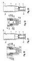
- Fig. 1
- shows a perspective exploded view of the extension device according to a first embodiment.
- Fig. 2
- shows a perspective view of the extension device of
Fig. 1 in an assembled state. - Fig. 3
- shows a perspective view of a first embodiment of a receiving part of a bone anchor that may form together with the extension device of
Figs. 1 and 2 a first embodiment of a system of an extension device and a bone anchor. - Fig. 4
- shows a top view of the receiving part of
Fig. 3 . - Fig. 5a
- shows a cross-sectional view of the receiving part of
Fig. 3 along line A-A inFig. 4 . - Fig. 5b
- shows an enlarged view of a detail of
Fig. 5a . - Fig. 6
- shows a perspective view of a first sleeve of the extension device of
Figs. 1 and 2 . - Fig. 7
- shows a perspective view from the bottom of a front end portion of the first sleeve of
Fig. 6 . - Fig. 8
- shows a top view of the first sleeve of
Fig. 6 . - Fig. 9
- shows a cross-sectional view of the first sleeve of
Fig. 6 along line B-B inFig. 8 . - Fig. 10
- shows a cross-sectional view of the first sleeve of
Fig. 6 along line D-D inFig. 9 . - Fig. 11a
- shows a perspective view of a second sleeve of the extension device of
Figs. 1 and 2 . - Fig. 11b
- shows an enlarged perspective view of a detail of
Fig. 11a . - Fig. 12
- shows a cross-sectional view of the second sleeve according to
Fig. 11a , the cross section taken in a plane containing a longitudinal sleeve axis and extending through the center of the legs of the sleeve. - Fig. 13
- shows a perspective view of an interlocking bushing of the extension device of
Figs. 1 and 2 . - Fig. 14
- shows a cross-sectional view of the interlocking bushing of
Fig. 13 , the section taken in a plane containing a cylinder axis of the bushing. - Fig. 15
- shows a perspective view of a first step of assembling the extension device of
Figs. 1 and 2 , wherein the interlocking bushing ofFig. 13 is to be mounted to the rear end section of the second sleeve ofFig. 11a . - Fig. 16
- shows a perspective view of the interlocking bushing and the first sleeve of
Fig. 15 mounted together. - Figs. 17 to 19a
- show cross-sectional views of steps of attaching the extension device of the first embodiment to a polyaxial bone anchor.
- Fig. 19b
- shows an enlarged view of a detail of
Fig. 19a . - Fig. 20
- shows a cross-sectional view of the bone anchor with attached extension device according to the first embodiment in a state before the extension device is rotationally locked with respect to the bone anchor.
- Fig. 21
- shows a cross-sectional view of an upper portion of the extension device in the state shown in
Fig. 20 . - Fig. 22
- shows an enlarged cross-sectional view of the bone anchor extension device in a state in that the extension device is rotationally locked with respect to the bone anchor.
- Fig. 23
- shows a cross-sectional view of the upper portion of the extension device in the state shown in
Fig. 22 . - Fig. 24
- shows a perspective view of a receiving part according to a second embodiment that forms together with an extension device according to a second embodiment a second embodiment of a system of an extension device and a bone anchor.
- Fig. 25
- shows an enlarged perspective view of a front end portion of first sleeve of the extension device according to the second embodiment.
- Fig. 26
- shows a perspective view of the front end portion of the extension device according to the second embodiment with a bone anchor having a receiving part according to the second embodiment shown in
Fig. 24 . - Fig. 27
- shows an enlarged perspective view of a front end portion of a second sleeve of the extension device according to the second embodiment.
- Figs. 28 to 30a
- show cross-sectional views of steps of attaching the extension device according to
Figs. 25 to 27 to a polyaxial bone anchor. - Fig. 30b
- shows an enlarged view of a detail of
Fig. 30a . - Fig. 31
- shows an enlarged perspective view of a modified embodiment of a second sleeve of an extension device.
- Fig. 32
- shows a perspective view of a front end portion of a still further modified embodiment of the second sleeve.
- Fig. 33
- shows a perspective view of a section of the spinal column with inserted pedicle screws and attached extension devices according to the invention.
- Referring to
Figs. 1 and 2 , an extension device according to a first embodiment comprises afirst sleeve 1 that forms an outer sleeve, asecond sleeve 2 that forms an inner sleeve and that is positionable within thefirst sleeve 1 and an interlockingbushing 3. The interlockingbushing 3 is configured to be connected to thesecond sleeve 2 and is configured to couple thesecond sleeve 2 to thefirst sleeve 1 and to permit a controlled motion of thesecond sleeve 2 relative to thefirst sleeve 1. - The extension device shown in
Figs. 1 and 2 is configured to be used with a bone anchor that shall be explained first. An example of a such a bone anchor comprises an anchoring element with threadedshank 100 and a spherical segment shapedhead 101, as shown inFigs. 17 to 19a wherein the anchoring element is pivotably coupled to a receivingpart 200. The receivingpart 200 is shown more in detail inFigs. 3 to 5b . The receivingpart 200 typically is a substantially cylindrical part with a first end ortop end 200a and a second orbottom end 200b, a central axis C, acoaxial bore 201 extending from thetop end 200a to a distance from thebottom end 200b, aseat 202 for thehead 101 of the anchoring element and alower opening 203 at the bottom end through which the shank of the bone anchoring element can pass through. A substantiallyU-shaped recess 204 extends from thetop end 200a in the direction of thebottom end 200b. Therecess 204 serves for receiving a rod (not shown). By means of therecess 204 twofree legs legs top end 200a, circumferentially extendinggrooves U-shaped recess 204 to the other end and that are open towards theU-shaped recess 204. Anupper side wall 206a', 206b' and alower side wall 206a", 206b" of thegroove bottom end 200b. - The receiving
part 200 further comprises at thetop end 200a in a free end surface of each of thelegs recess recess Fig. 5b , a cross-section of therecesses recesses top end 200a there may be a chamferedsection 208 provided at eachrecess - In an upper portion of the legs, an
internal thread 209 is provided for cooperation with a locking screw (not shown) for fixing the rod. - Referring to
Figs. 6 to 10 , thefirst sleeve 1 of the extension device comprises a longitudinal axis c that is coaxial with the central axis C of the receivingpart 200 when the extension device is coupled to the receiving part. Thefirst sleeve 1 further has afront end 1a and arear end 1b. - The
first sleeve 1 comprises adjacent to the rear end 1bafirst section 11 with a largest inner diameter compared to other sections of thefirst sleeve 1. Twocoaxial slits second end 1b along at least a portion of thefirst section 11 in a longitudinal direction. One of the sidewalls of eachlongitudinal slit Fig. 6 for latching with a reduction sleeve (not shown) used for further steps in the surgical procedure, for example for pressing down the rod and inserting a locking screw to fix the rod. Furthermore, anengagement structure 13, for example, a plurality of flat engagement portions, is provided at an outer surface of thefirst section 11 that form anengagement portion 13 for engagement with a tool. Following thefirst section 11, thefirst sleeve 1 comprises asecond section 14 with slightly smaller inner diameter than thefirst section 11 and adjacent thereto athird section 15 with a smaller inner diameter compared to thesecond section 14 andfirst section 13. In the third section, aninternal thread 16 is provided that is configured to cooperate with the interlockingbushing 3 as described below. - Two elongate substantially
U-shaped slits 17a, 17b which have a reverse U-shape compared to theslit 204 in the receiving part and that are offset from each other by 180° extend from thefront end 1a toward therear end 1b up to a distance from thesecond section 14 of the first sleeve. Thelongitudinal slits 17a, 17b have a width in circumferential direction that is greater than a diameter of the rod and have the function of permitting the rod to be inserted therethrough. The width of theslits 17a, 17b may be substantially the same as the width of theU-shaped recess 204 in the receivingpart 200. By means of theslits 17a, 17b, thefirst sleeve 1 comprises twofree legs free legs part 200. The inner surface of thethird section 15 of thefirst sleeve 1 comprises at each of thelegs guiding recess longitudinal recesses 17a, 17b toward therear end 1b, as can be seen inFig. 9 . - Each of the
legs front end 1a aprojection slit 17a to the opposite slit 17b. The shape of thecircumferential projection circumferential grooves Fig. 19b . An upper surface of theprojection rear end 1b may be inclined toward the rear end to match the complementary inclinedupper wall 206a', 206b' of thegroove circumferential projection rear end 1b. Between theprojection recesses inner surface portion part 200 between thegrooves top end 200a. - By means of the
legs first sleeve 1 can be snapped onto thelegs part 200. - An outer diameter of the
first sleeve 1 may vary between therear end 1b and thefront end 1a. Thefirst sleeve 1 may have a greatest outer diameter in thefirst section 11 followed by one or more successively decreasing outer diameters towards thefront end 1a as shown inFig. 9 . In addition, flattenedouter surface portions 122a, 122b may be provided at an outer surface of thelegs front end 1 a toward therear end 1b for cooperation with a tool (not shown). - The total length of the first sleeve is such that when the bone anchor is inserted into the bone and the first sleeve is attached to the receiving
part 200, the rear end andfirst section 11 are sufficiently above the operation site when the extension device is used. - Referring now to
Figs. 11a to 12 , thesecond sleeve 2 comprises afront end 2a and an oppositerear end 2b. Thesecond sleeve 2 has a substantially constant outer diameter. Adjacent to therear end 2b, thesecond sleeve 2 comprises afirst portion 21 with a circumferentially closed cylinder surface, wherein thefirst portion 21 is configured to engage the interlockingbushing 3. A plurality of coaxially extendingslits 22 that are open end to therear end 2b and that extend to a distance from therear end 2b are provided to render thefirst portion 21 flexible in such a way that thefirst portion 21 can elastically snap onto a portion of the interlockingbushing 3 and is held there by friction. At a first distance from therear end 2b a circumferentially extendingannular projection 23 projecting inward is provided that cooperates with a corresponding depression or recess at the interlockingbushing 3 to inhibit an inadvertent removal of the interlockingbushing 3 from thesecond sleeve 2. At a second distance from therear end 2b astop 21 a, for example in the form of an annular shoulder is provided that limits the insertion of the interlockingbushing 3 and provides an abutment for the interlockingbushing 3 when the interlocking bushing is screwed into thefirst sleeve 1. An outer diameter of thefirst section 21 of thesecond sleeve 2 is such that is fits intothird section 15 of thefirst sleeve 1. - Two
recesses 24a, 24b with substantially rectangular cross section extend from thefront end 2a through thesecond sleeve 2 up to thefirst portion 21. The recesses have such a size that twoopposite legs recesses first sleeve 1. Thelegs recesses 17a, 17b of thefirst sleeve 1 in a direction toward therear end 1b of thefirst sleeve 1. Thefront end 2a of thesecond sleeve 2 is comprised of a substantiallyflat surface portion legs top end 200a of the receiving part, and aprojection recess part 200. Hence, theprojection recess Fig. 11b , a side surface of theprojection 27a that faces toward the longitudinal axis of thesecond sleeve 2 is flush with the inner surface of thelegs projections legs projections corresponding recess projection legs - Turning now to
Figs. 13 and 14 , the interlockingbushing 3 comprises afront end 3 a and arear end 3b and acylindrical section 31 that is adjacent to thefront end 3a and that has an outer diameter that is substantially the same as an inner diameter of thefirst section 21 of thesecond sleeve 2. The size of the inner portion of thefirst section 21 of thesecond sleeve 2 and thecylindrical section 31 of thebushing 3 is such that thebushing 3 is held in thesecond sleeve 2 by friction. Adjacent to thecylindrical section 31 with a smooth outer surface, there is agroove 32 for engaging with theannular projection 23 of thesecond sleeve 2. Adjacent to therear end 3b, a threadedportion 33 with an external thread is provided that is configured to cooperate with the threadedsection 16 of thefirst sleeve 1. An inner diameter of thebushing 3 may be substantially constant and sized such that a locking member for fixing the rod in the receiving part can be inserted therethrough. Adjacent to therear end 3b, the inner surface of thebushing 3 comprises anengagement portion 34, for example, a plurality of longitudinally extending grooves and projections for engaging with a tool. - The assembly of the
second sleeve 2 and the interlockingbushing 3 is shown inFig. 15 and 16 . The interlocking bushing is pushed with itscylindrical portion 31 into thefirst section 21 of thesecond sleeve 2 until the inwardly projectingannular projection 23 snaps into thegroove 32 of the interlockingbushing 3. By means of this, the interlockingbushing 3 is coupled to thesecond sleeve 2 in such a manner, that a rotational motion of the interlockingbushing 3 relative to thesecond sleeve 2 is possible. An axial movement of the interlockingbushing 3 relative to thesecond sleeve 2 is inhibited when the interlocking bushing abuts against thestop 21a provided in thesecond sleeve 2. The connection between thesecond sleeve 2 and thefirst sleeve 1 via the interlocking bushing is a rigid connection. - The assembly consisting of the
second sleeve 2 and the interlockingbushing 2 as shown inFig. 16 is then inserted into thefirst sleeve 1 from therear end 1b until the threadedportion 33 of the interlocking bushing engages the threadedsection 16 of thefirst sleeve 1. Thelegs recesses first sleeve 1. By means of this, the extension device is assembled. - Referring now to
Figs. 17 to 23 , the attachment of the extension device to a bone anchor will be described. As shown inFig. 17 , the extension device is moved with thefront end 1a of thefirst sleeve 1 toward the receivingpart 200. Then, as depicted inFig. 17 , thelegs top end 200a of the receivingpart 200 and by further downward movement of the extension device, thecircumferential projections legs first sleeve 1 snap into thecircumferential grooves part 200. As soon as the projections have engaged the recesses, an axial movement of thefirst sleeve 1 in a direction away from the receivingpart 200 is inhibited. - Then, as shown in
Figs. 19a and 19b , thesecond sleeve 2 is moved relative to thefirst sleeve 1 toward the receivingpart 200 by screwing the interlockingbushing 3 further towards thefront end 1a of thefirst sleeve 1. When theprojections second sleeve 2 enter the correspondingrecesses top end 200a of the receivingpart 200 a rotational movement of thesecond sleeve 2 relative to thefirst sleeve 1 and therefore relative to the receivingpart 200 is inhibited. Referring toFigs. 20 and 21 , a step of moving thesecond sleeve 2 relative to thefirst sleeve 1 is shown. InFig. 20 , the position of thesecond sleeve 2 relative to thefirst sleeve 1 which is already attached to the receivingpart 200 is such that theprojections recesses second section 14 of thefirst sleeve 1. InFig. 22 theprojections recesses Fig. 23 , by rotating the interlockingbushing 3 so that it advances in the threadedsection 16 of thefirst sleeve 1. Because the interlockingbushing 3 abuts against thestop 21 a in thesecond sleeve 2, the interlockingbushing 3 pushes thesecond sleeve 2 forward when it moves. Thesecond sleeve 2 can rotate relative to thebushing 3 so that the alignment between thelegs first sleeve 1 and thelegs second sleeve 2 is maintained. A further rotation of the interlockingbushing 3 presses theflat surface portion front end 2a of thesecond sleeve 2 onto the free flat end surfaces of the receivingpart 200. Through this and the engagement of theprojections grooves first sleeve 1 is interlocked with the receivingpart 200 and with thesecond sleeve 2 to provide a safe and strong connection between the extension device and the receiving part. In such a configuration, the insertion of the rod and locking screw can take place as well as surgical steps thereafter such as compression and distraction steps thereby using the extension device. - Turning the interlocking
bushing 3 in the opposite direction releases the interlocking connection and permits to retract theprojection second sleeve 2 out of therecesses part 200 by first removing thesecond sleeve 2 together with the interlockingbushing 3 and then using a tool for detaching the first sleeve such that thecircumferential projection grooves part 200. - A second embodiment of the extension device is shown in
Fig. 24 to 27 . All parts and portions of the second embodiment that are identical or similar to that of the first embodiment are marked with the identical reference numerals and the description thereof is not repeated. The second embodiment of the extension device differs from the first embodiment by the design of the front portion of the first sleeve and the second sleeve. Also the receiving part differs from the receiving part of the first embodiment. - The extension device according to the second embodiment comprises a first sleeve 1', a second sleeve 2' and the interlocking
bushing 3 that is the same as in the first embodiment. As can be seen inFig. 24 , the receiving part 200' comprises in addition to thecircumferential grooves leg recess top end 200a. Therecesses legs legs recesses leg recesses circumferential grooves recesses - Referring to
Figs. 25 and 26 , the first sleeve 1' comprises twoprojections front end 1a toward the longitudinal axis c and that are positioned, sized and shaped complementary to therecesses Fig. 26 , theprojections leg projections coaxial recesses - The second sleeve 2' differs from the
second sleeve 2 of the first embodiment in that theprojections front end 2a of the second sleeve 2' comprises only two arc shapedflat surfaces 26a', 26b' corresponding to eachleg Fig. 27 . - The attachment of the extension device to the receiving part 200' will be explained with reference to
Figures 28 to 30b . First, as shown inFig. 28 , the extension device according to the second embodiment is moved with itsfront end 1a of the first sleeve 1' toward the receiving part 200' in such a manner that thelegs legs coaxial projections coaxial recesses circumferential projections circumferential grooves bushing 3 until thefree end surfaces 26a', 26b' abut against thefree end surface 200a of the first end of the receiving part 200' as shown in detail inFig. 30b . Final tightening of the interlockingbushing 3 generates a force-fit connection between the abutting surfaces of the second sleeve 2' and the receiving part 200' and an interlocking of the extension device relative to the receiving part. Through rotating the interlockingbushing 3 in the opposite direction the connection is released. - A modified embodiment of the design of the second sleeve is shown in
Fig. 31 . Thesecond sleeve 2" may have at itsfront end 2a instead of theprojection first embodiment projections legs projections leg projections - A still further modified embodiment of the second sleeve is shown in
Fig. 32 . The second sleeve 2'" comprises at itsfront end 2a tworecesses legs - The parts of the extension device are all made of a body-compatible material, such as titanium or stainless steel, a body-compatible metal alloy, for example Ti-Ni alloy, such as Nitinol, or a body-compatible plastic material, such as PEEK.
- In use, as shown in
Fig. 33 , an extension device according to each of the embodiments described above is attached to a receivingpart 200 of a bone anchor that has been inserted into a pedicle of avertebra legs - Modifications of the above described embodiments may be contemplated. It shall be noted, that the shape of the engaging complementary structures of the first sleeve and the receiving part as well as the second sleeve and the receiving part can be modified and are not limited to the exact shape shown in the embodiments.
- The extension device can be used with any bone anchor that comprises a receiving part, such as polyaxial bone anchor, a monoaxial bone anchor and to different shapes of receiving parts. Anchors with inner compression members or outer rings may be used. The only necessity is the engagement structure at an upper end of the receiving part that cooperates with a corresponding structure of the extension device.
Claims (15)
- An extension device for a bone anchor, wherein the bone anchor comprises an anchoring section (100) for anchoring in a bone and
a receiving part (200, 200') connected to the anchoring section, the receiving part comprising a central axis (C) and a channel (204) for receiving a rod, wherein sidewalls of the channel form two free legs (205a, 205b),
the extension device comprising
a first sleeve (1, 1') with a first sleeve axis (c) that is coaxial with the central axis (C),
wherein the first sleeve (1, 1') is configured to be detachably coupled to the receiving part (200, 200') and
a second sleeve (2, 2', 2", 2"') with a second sleeve axis, wherein the second sleeve is positioned within the first sleeve (1, 1'),
wherein the first sleeve (1, 1') is configured to contact to the receiving part (200, 200') such as to inhibit a translational movement of the first sleeve relative to the receiving part along the central axis and
wherein the second sleeve (2, 2', 2", 2"') is configured to be coupled to the receiving part so as to hinder or inhibit a rotational movement of the second sleeve (2, 2', 2", 2"') relative to the receiving part (200, 200');
characterized in that the second sleeve (2, 2', 2", 2"') is connected to the first sleeve (1, 1') through a coupling member (3) that is configured to advance in the first sleeve (1, 1') together with the second sleeve (2, 2', 2", 2"') in an axial direction. - The extension device of claim 1, wherein the the coupling member (3) is coupled to the first sleeve (1, 1') through an advancement structure (33, 16) that permits to advance the coupling member with the second sleeve (2, 2', 2", 2"') to a given position.
- The extension device of claim 1 or 2, wherein the coupling member (3) is a bushing and the advancement structure comprises threads (33, 16).
- The extension device of claim 3, wherein the second sleeve (2, 2', 2", 2"') is coupled to the first sleeve in a rigid manner.
- The extension device of one of claims 1 to 4, wherein the coupling member (3) is coupled to the second sleeve (2, 2', 2", 2"') so that it can rotate with respect to the second sleeve.
- The extension device of one of claims 1 to 5, wherein the second sleeve (2, 2', 2", 2"') comprises an abutment (21a) for the coupling member (3).
- The extension device of one of claims 1 to 6, wherein the first sleeve (1, 1') comprises a protrusion (120a, 120b) and/or a recess at an inner surface thereof that is configured to engage a complementary structure (206a, 206b) at an outer surface of the receiving element (200, 200') to provide a form-fit connection between the first sleeve (1, 1') and the receiving part (200, 200').
- The extension device of claim 7, wherein the protrusion (120a, 120b) and/or recess at the first sleeve (1, 1') and the complementary structure (206a, 206b) at the receiving part are shaped so as to inhibit an axial movement of the first sleeve relative to the receiving part.
- The extension device of claim 7 or 8, wherein the protrusion (129a, 129b) and/or recess at the first sleeve (1') and the complementary structure (210a, 210b) at the receiving part (200') are shaped so as to inhibit a rotational movement of the first sleeve relative to the receiving part.
- The extension device of one of claims 1 to 9, wherein the second sleeve (2, 2", 2"') comprises a protrusion (27a, 27b; 270a, 270b) and/or a recess (290a, 290b) at a surface thereof that is configured to engage a complementary structure at a surface of the receiving part to provide a form-fit connection between the second sleeve and the receiving part.
- The extension device of one of claims 1 to 10, wherein the second sleeve (2') comprises a substantially flat surface portion (26a', 26b') that is configured to engage a substantially flat surface portion (200a) at the receiving part (200') such that a friction between the surface portions is generated when the first sleeve is rotated relative to the second sleeve.
- The extension device of one of claims 1 to 11, wherein the first sleeve (1, 1') comprises a first end (1a) and an opposite second end (1b) and wherein the first sleeve (1, 1') comprises a longitudinal recess(17a, 17b) that extends in an axial direction and that is open to the second end, the width of the recess preferably being adapted to the width of the channel (204) for the rod of the receiving part (200, 200').
- The extension device of one of claims 1 to 12, wherein the second sleeve (2, 2', 2", 2"') comprises a first end (2a) and an opposite second end (2b) and wherein the second sleeve comprises a longitudinal recess (24a, 24b) that extends in an axial direction and that is open to the second end, the width of recess preferably being adapted ot the width of the channel (204) for the rod of the receiving part.
- A system of an extension device according to one of claims 1 to 12 and a bone anchor, wherein the bone anchor comprises
the anchoring section (100) for anchoring in a bone and
the receiving part (200, 200') connected to the anchoring section, the receiving part comprising a central axis (C) and a channel (204) for receiving a rod, wherein sidewalls of the channel form two free legs (205a, 205b). - A spinal stabilization system for use with minimally invasive surgery comprising a system of claim 14 with at least two bone anchors and an extension device for each bone anchor according to one of claims 1 to 13.
Priority Applications (7)
| Application Number | Priority Date | Filing Date | Title |
|---|---|---|---|
| EP13196326.6A EP2881053B1 (en) | 2013-12-09 | 2013-12-09 | Extension device for a bone anchor, in particular for minimally invasive surgery |
| JP2014245817A JP6430225B2 (en) | 2013-12-09 | 2014-12-04 | Extension device and bone anchor system, and spinal stabilization system used for minimally invasive surgery |
| TW103142073A TW201526860A (en) | 2013-12-09 | 2014-12-04 | Extension device for a bone anchor, in particular for minimally invasive surgery |
| CN201410730039.9A CN104706405B (en) | 2013-12-09 | 2014-12-04 | For the extension apparatus of bone anchor, the system that is made of bone anchor and extension apparatus and vertebral stabilization system |
| KR1020140175229A KR20150067062A (en) | 2013-12-09 | 2014-12-08 | Extension device for a bone anchor, in particular for minimally invasive surgery |
| EP14196976.6A EP2881056B1 (en) | 2013-12-09 | 2014-12-09 | Extension device for a bone anchor, in particular for minimally invasive surgery |
| US14/565,365 US9492209B2 (en) | 2013-12-09 | 2014-12-09 | Extension device for a bone anchor, in particular for minimally invasive surgery |
Applications Claiming Priority (1)
| Application Number | Priority Date | Filing Date | Title |
|---|---|---|---|
| EP13196326.6A EP2881053B1 (en) | 2013-12-09 | 2013-12-09 | Extension device for a bone anchor, in particular for minimally invasive surgery |
Publications (2)
| Publication Number | Publication Date |
|---|---|
| EP2881053A1 true EP2881053A1 (en) | 2015-06-10 |
| EP2881053B1 EP2881053B1 (en) | 2018-01-31 |
Family
ID=49880383
Family Applications (2)
| Application Number | Title | Priority Date | Filing Date |
|---|---|---|---|
| EP13196326.6A Active EP2881053B1 (en) | 2013-12-09 | 2013-12-09 | Extension device for a bone anchor, in particular for minimally invasive surgery |
| EP14196976.6A Active EP2881056B1 (en) | 2013-12-09 | 2014-12-09 | Extension device for a bone anchor, in particular for minimally invasive surgery |
Family Applications After (1)
| Application Number | Title | Priority Date | Filing Date |
|---|---|---|---|
| EP14196976.6A Active EP2881056B1 (en) | 2013-12-09 | 2014-12-09 | Extension device for a bone anchor, in particular for minimally invasive surgery |
Country Status (6)
| Country | Link |
|---|---|
| US (1) | US9492209B2 (en) |
| EP (2) | EP2881053B1 (en) |
| JP (1) | JP6430225B2 (en) |
| KR (1) | KR20150067062A (en) |
| CN (1) | CN104706405B (en) |
| TW (1) | TW201526860A (en) |
Cited By (1)
| Publication number | Priority date | Publication date | Assignee | Title |
|---|---|---|---|---|
| EP3415107A1 (en) * | 2017-06-12 | 2018-12-19 | Biedermann Technologies GmbH & Co. KG | Bone anchor |
Families Citing this family (26)
| Publication number | Priority date | Publication date | Assignee | Title |
|---|---|---|---|---|
| EP2574297B1 (en) | 2011-09-30 | 2015-11-11 | Biedermann Technologies GmbH & Co. KG | Bone anchoring device and tool cooperating with such a bone anchoring device |
| FR2988582B1 (en) * | 2012-04-02 | 2014-03-14 | Safe Orthopaedics | INSTRUMENTATION KIT |
| US9370383B2 (en) | 2013-03-15 | 2016-06-21 | Zimmer Biomet Spine, Inc. | Minimally invasive splitable pedicle screw extender |
| EP2996591B1 (en) * | 2013-05-13 | 2020-11-04 | Neo Medical SA | Orthopedic implant kit |
| FR3018678B1 (en) * | 2014-03-20 | 2016-03-11 | Spineway | SURGICAL ASSEMBLY, BONE ANCHORING SCREW AND DEVICE FOR EXTENSION OF SUCH SCREWS FORMING PART OF SAID SURGICAL ASSEMBLY |
| US9526553B2 (en) * | 2014-04-04 | 2016-12-27 | K2M, Inc. | Screw insertion instrument |
| US10568667B2 (en) | 2016-07-13 | 2020-02-25 | Medos International Sàrl | Bone anchor assemblies and related instrumentation |
| US10463402B2 (en) | 2016-07-13 | 2019-11-05 | Medos International Sàrl | Bone anchor assemblies and related instrumentation |
| US10874438B2 (en) | 2016-07-13 | 2020-12-29 | Medos International Sarl | Bone anchor assemblies and related instrumentation |
| US10363073B2 (en) | 2016-07-13 | 2019-07-30 | Medos International Sàrl | Bone anchor assemblies and related instrumentation |
| EP3473198B1 (en) | 2016-08-04 | 2023-02-22 | Biedermann Technologies GmbH & Co. KG | Polyaxial bone anchoring device and system of an instrument and a polyaxial bone anchoring device |
| US10064662B2 (en) | 2016-08-12 | 2018-09-04 | Amendia, Inc. | Minimally invasive screw extension assembly |
| EP3287089B1 (en) | 2016-08-24 | 2019-07-24 | Biedermann Technologies GmbH & Co. KG | Polyaxial bone anchoring device and system of an instrument and a polyaxial bone anchoring device |
| US10779866B2 (en) | 2016-12-29 | 2020-09-22 | K2M, Inc. | Rod reducer assembly |
| WO2018167381A1 (en) * | 2017-03-15 | 2018-09-20 | Onecox | Intraosseous guide pin, trocar for installing and trocar for withdrawing said pin |
| EP3476340B1 (en) | 2017-10-25 | 2021-06-02 | Biedermann Technologies GmbH & Co. KG | Polyaxial bone anchoring device |
| US10966762B2 (en) | 2017-12-15 | 2021-04-06 | Medos International Sarl | Unilateral implant holders and related methods |
| USD902405S1 (en) | 2018-02-22 | 2020-11-17 | Stryker Corporation | Self-punching bone anchor inserter |
| EP3536271B1 (en) | 2018-03-06 | 2022-05-04 | Biedermann Technologies GmbH & Co. KG | Polyaxial bone anchoring device and system of an instrument and a polyaxial bone anchoring device |
| TWI682761B (en) * | 2018-10-09 | 2020-01-21 | 台灣微創醫療器材股份有限公司 | Device for surgery of stabilizing bone segments, extending assembly, fastening member and assembing method thereof |
| US11484350B2 (en) | 2018-12-13 | 2022-11-01 | Zimmer Biomet Spine, Inc. | Split tower for a bone anchor |
| US11559337B2 (en) | 2018-12-14 | 2023-01-24 | Zimmer Biomet Spine, Inc. | Expended tab reinforcement sleeve |
| USD1004774S1 (en) | 2019-03-21 | 2023-11-14 | Medos International Sarl | Kerrison rod reducer |
| US11291482B2 (en) | 2019-03-21 | 2022-04-05 | Medos International Sarl | Rod reducers and related methods |
| US11291481B2 (en) | 2019-03-21 | 2022-04-05 | Medos International Sarl | Rod reducers and related methods |
| DE102019116374A1 (en) * | 2019-06-17 | 2020-12-17 | Aesculap Ag | Partially blocked pedicle screw II |
Citations (5)
| Publication number | Priority date | Publication date | Assignee | Title |
|---|---|---|---|---|
| US7563264B2 (en) | 2002-10-30 | 2009-07-21 | Zimmer Spine Austin, Inc. | Spinal stabilization systems and methods |
| US20120022594A1 (en) * | 2010-07-26 | 2012-01-26 | Spinal USA LLC | Minimally invasive surgical tower access devices and related methods |
| US8211110B1 (en) * | 2006-11-10 | 2012-07-03 | Lanx, Inc. | Minimally invasive tool to facilitate implanting a pedicle screw and housing |
| US8439922B1 (en) * | 2008-02-06 | 2013-05-14 | NiVasive, Inc. | Systems and methods for holding and implanting bone anchors |
| WO2013112689A2 (en) | 2012-01-25 | 2013-08-01 | Spinal Usa, Inc. | Minimally invasive devices and methods for delivering fixation devices and implants into a spine |
Family Cites Families (8)
| Publication number | Priority date | Publication date | Assignee | Title |
|---|---|---|---|---|
| US7179261B2 (en) * | 2003-12-16 | 2007-02-20 | Depuy Spine, Inc. | Percutaneous access devices and bone anchor assemblies |
| US8038699B2 (en) | 2006-09-26 | 2011-10-18 | Ebi, Llc | Percutaneous instrument assembly |
| EP2088945A4 (en) * | 2006-12-08 | 2010-02-17 | Roger P Jackson | Tool system for dynamic spinal implants |
| US8016832B2 (en) * | 2007-05-02 | 2011-09-13 | Zimmer Spine, Inc. | Installation systems for spinal stabilization system and related methods |
| US8414588B2 (en) * | 2007-10-04 | 2013-04-09 | Depuy Spine, Inc. | Methods and devices for minimally invasive spinal connection element delivery |
| WO2013187928A1 (en) | 2012-06-14 | 2013-12-19 | Spine Wave, Inc. | Pedicle screw extension for use in percutaneous spinal fixation |
| DE102012107056A1 (en) | 2012-08-01 | 2014-05-15 | Aesculap Ag | Surgical instruments |
| US9066761B2 (en) | 2012-08-17 | 2015-06-30 | Warsaw Orthopedic, Inc. | Spinal implant system and method |
-
2013
- 2013-12-09 EP EP13196326.6A patent/EP2881053B1/en active Active
-
2014
- 2014-12-04 TW TW103142073A patent/TW201526860A/en unknown
- 2014-12-04 JP JP2014245817A patent/JP6430225B2/en not_active Expired - Fee Related
- 2014-12-04 CN CN201410730039.9A patent/CN104706405B/en not_active Expired - Fee Related
- 2014-12-08 KR KR1020140175229A patent/KR20150067062A/en not_active Application Discontinuation
- 2014-12-09 US US14/565,365 patent/US9492209B2/en active Active
- 2014-12-09 EP EP14196976.6A patent/EP2881056B1/en active Active
Patent Citations (5)
| Publication number | Priority date | Publication date | Assignee | Title |
|---|---|---|---|---|
| US7563264B2 (en) | 2002-10-30 | 2009-07-21 | Zimmer Spine Austin, Inc. | Spinal stabilization systems and methods |
| US8211110B1 (en) * | 2006-11-10 | 2012-07-03 | Lanx, Inc. | Minimally invasive tool to facilitate implanting a pedicle screw and housing |
| US8439922B1 (en) * | 2008-02-06 | 2013-05-14 | NiVasive, Inc. | Systems and methods for holding and implanting bone anchors |
| US20120022594A1 (en) * | 2010-07-26 | 2012-01-26 | Spinal USA LLC | Minimally invasive surgical tower access devices and related methods |
| WO2013112689A2 (en) | 2012-01-25 | 2013-08-01 | Spinal Usa, Inc. | Minimally invasive devices and methods for delivering fixation devices and implants into a spine |
Cited By (2)
| Publication number | Priority date | Publication date | Assignee | Title |
|---|---|---|---|---|
| EP3415107A1 (en) * | 2017-06-12 | 2018-12-19 | Biedermann Technologies GmbH & Co. KG | Bone anchor |
| US11109893B2 (en) | 2017-06-12 | 2021-09-07 | Biedermann Technologies Gmbh & Co. Kg | Bone anchor |
Also Published As
| Publication number | Publication date |
|---|---|
| EP2881056B1 (en) | 2018-05-30 |
| KR20150067062A (en) | 2015-06-17 |
| TW201526860A (en) | 2015-07-16 |
| EP2881056A1 (en) | 2015-06-10 |
| US20150182265A1 (en) | 2015-07-02 |
| CN104706405B (en) | 2019-05-14 |
| JP2015112479A (en) | 2015-06-22 |
| JP6430225B2 (en) | 2018-11-28 |
| EP2881053B1 (en) | 2018-01-31 |
| CN104706405A (en) | 2015-06-17 |
| US9492209B2 (en) | 2016-11-15 |
Similar Documents
| Publication | Publication Date | Title |
|---|---|---|
| EP2881053B1 (en) | Extension device for a bone anchor, in particular for minimally invasive surgery | |
| US11083499B2 (en) | Polyaxial bone anchoring device and instrument for use with the same | |
| US20210338287A1 (en) | Coupling assembly for coupling a rod to a bone anchoring element, polyaxial bone anchoring device and modular stabilization device | |
| EP2957246B1 (en) | Extension device for a bone anchor, in particular for minimally invasive surgery | |
| US7226453B2 (en) | Instrument for inserting, adjusting and removing pedicle screws and other orthopedic implants | |
| CN106137364B (en) | Coupling device and bone anchoring device | |
| JP6525649B2 (en) | Device for placing a receiving part on the head of a bone anchor element and system for connecting a bone anchor element to a spinal rod | |
| US8414588B2 (en) | Methods and devices for minimally invasive spinal connection element delivery | |
| EP2676621B1 (en) | Bone Anchor | |
| JP6556117B2 (en) | Spine stabilization system and surgical fastening element for spinal stabilization system | |
| EP3473198B1 (en) | Polyaxial bone anchoring device and system of an instrument and a polyaxial bone anchoring device | |
| EP3092962B1 (en) | Instrument for use with a polyaxial bone anchoring device and system including the instrument and a polyaxial bone anchoring device | |
| US20210401466A1 (en) | Polyaxial bone anchoring device and system including an instrument and a polyaxial bone anchoring device | |
| US20220160401A1 (en) | Coupling device and instrument for connecting the coupling device to a head of a bone anchor | |
| US11602377B2 (en) | Receiving part for coupling a rod to a bone anchor |
Legal Events
| Date | Code | Title | Description |
|---|---|---|---|
| PUAI | Public reference made under article 153(3) epc to a published international application that has entered the european phase |
Free format text: ORIGINAL CODE: 0009012 |
|
| 17P | Request for examination filed |
Effective date: 20131209 |
|
| AK | Designated contracting states |
Kind code of ref document: A1 Designated state(s): AL AT BE BG CH CY CZ DE DK EE ES FI FR GB GR HR HU IE IS IT LI LT LU LV MC MK MT NL NO PL PT RO RS SE SI SK SM TR |
|
| AX | Request for extension of the european patent |
Extension state: BA ME |
|
| R17P | Request for examination filed (corrected) |
Effective date: 20151210 |
|
| RBV | Designated contracting states (corrected) |
Designated state(s): AL AT BE BG CH CY CZ DE DK EE ES FI FR GB GR HR HU IE IS IT LI LT LU LV MC MK MT NL NO PL PT RO RS SE SI SK SM TR |
|
| 17Q | First examination report despatched |
Effective date: 20160704 |
|
| GRAP | Despatch of communication of intention to grant a patent |
Free format text: ORIGINAL CODE: EPIDOSNIGR1 |
|
| RIC1 | Information provided on ipc code assigned before grant |
Ipc: A61B 17/70 20060101AFI20170531BHEP |
|
| INTG | Intention to grant announced |
Effective date: 20170704 |
|
| GRAS | Grant fee paid |
Free format text: ORIGINAL CODE: EPIDOSNIGR3 |
|
| GRAA | (expected) grant |
Free format text: ORIGINAL CODE: 0009210 |
|
| AK | Designated contracting states |
Kind code of ref document: B1 Designated state(s): AL AT BE BG CH CY CZ DE DK EE ES FI FR GB GR HR HU IE IS IT LI LT LU LV MC MK MT NL NO PL PT RO RS SE SI SK SM TR |
|
| REG | Reference to a national code |
Ref country code: GB Ref legal event code: FG4D Ref country code: CH Ref legal event code: EP |
|
| REG | Reference to a national code |
Ref country code: AT Ref legal event code: REF Ref document number: 966631 Country of ref document: AT Kind code of ref document: T Effective date: 20180215 Ref country code: CH Ref legal event code: NV Representative=s name: NOVAGRAAF INTERNATIONAL SA, CH |
|
| REG | Reference to a national code |
Ref country code: IE Ref legal event code: FG4D |
|
| REG | Reference to a national code |
Ref country code: DE Ref legal event code: R096 Ref document number: 602013032539 Country of ref document: DE |
|
| REG | Reference to a national code |
Ref country code: NL Ref legal event code: MP Effective date: 20180131 |
|
| REG | Reference to a national code |
Ref country code: LT Ref legal event code: MG4D |
|
| REG | Reference to a national code |
Ref country code: AT Ref legal event code: MK05 Ref document number: 966631 Country of ref document: AT Kind code of ref document: T Effective date: 20180131 |
|
| PG25 | Lapsed in a contracting state [announced via postgrant information from national office to epo] |
Ref country code: ES Free format text: LAPSE BECAUSE OF FAILURE TO SUBMIT A TRANSLATION OF THE DESCRIPTION OR TO PAY THE FEE WITHIN THE PRESCRIBED TIME-LIMIT Effective date: 20180131 Ref country code: LT Free format text: LAPSE BECAUSE OF FAILURE TO SUBMIT A TRANSLATION OF THE DESCRIPTION OR TO PAY THE FEE WITHIN THE PRESCRIBED TIME-LIMIT Effective date: 20180131 Ref country code: NO Free format text: LAPSE BECAUSE OF FAILURE TO SUBMIT A TRANSLATION OF THE DESCRIPTION OR TO PAY THE FEE WITHIN THE PRESCRIBED TIME-LIMIT Effective date: 20180430 Ref country code: HR Free format text: LAPSE BECAUSE OF FAILURE TO SUBMIT A TRANSLATION OF THE DESCRIPTION OR TO PAY THE FEE WITHIN THE PRESCRIBED TIME-LIMIT Effective date: 20180131 Ref country code: NL Free format text: LAPSE BECAUSE OF FAILURE TO SUBMIT A TRANSLATION OF THE DESCRIPTION OR TO PAY THE FEE WITHIN THE PRESCRIBED TIME-LIMIT Effective date: 20180131 Ref country code: FI Free format text: LAPSE BECAUSE OF FAILURE TO SUBMIT A TRANSLATION OF THE DESCRIPTION OR TO PAY THE FEE WITHIN THE PRESCRIBED TIME-LIMIT Effective date: 20180131 |
|
| PG25 | Lapsed in a contracting state [announced via postgrant information from national office to epo] |
Ref country code: IS Free format text: LAPSE BECAUSE OF FAILURE TO SUBMIT A TRANSLATION OF THE DESCRIPTION OR TO PAY THE FEE WITHIN THE PRESCRIBED TIME-LIMIT Effective date: 20180531 Ref country code: GR Free format text: LAPSE BECAUSE OF FAILURE TO SUBMIT A TRANSLATION OF THE DESCRIPTION OR TO PAY THE FEE WITHIN THE PRESCRIBED TIME-LIMIT Effective date: 20180501 Ref country code: PL Free format text: LAPSE BECAUSE OF FAILURE TO SUBMIT A TRANSLATION OF THE DESCRIPTION OR TO PAY THE FEE WITHIN THE PRESCRIBED TIME-LIMIT Effective date: 20180131 Ref country code: SE Free format text: LAPSE BECAUSE OF FAILURE TO SUBMIT A TRANSLATION OF THE DESCRIPTION OR TO PAY THE FEE WITHIN THE PRESCRIBED TIME-LIMIT Effective date: 20180131 Ref country code: LV Free format text: LAPSE BECAUSE OF FAILURE TO SUBMIT A TRANSLATION OF THE DESCRIPTION OR TO PAY THE FEE WITHIN THE PRESCRIBED TIME-LIMIT Effective date: 20180131 Ref country code: AT Free format text: LAPSE BECAUSE OF FAILURE TO SUBMIT A TRANSLATION OF THE DESCRIPTION OR TO PAY THE FEE WITHIN THE PRESCRIBED TIME-LIMIT Effective date: 20180131 Ref country code: BG Free format text: LAPSE BECAUSE OF FAILURE TO SUBMIT A TRANSLATION OF THE DESCRIPTION OR TO PAY THE FEE WITHIN THE PRESCRIBED TIME-LIMIT Effective date: 20180430 Ref country code: RS Free format text: LAPSE BECAUSE OF FAILURE TO SUBMIT A TRANSLATION OF THE DESCRIPTION OR TO PAY THE FEE WITHIN THE PRESCRIBED TIME-LIMIT Effective date: 20180131 |
|
| PG25 | Lapsed in a contracting state [announced via postgrant information from national office to epo] |
Ref country code: AL Free format text: LAPSE BECAUSE OF FAILURE TO SUBMIT A TRANSLATION OF THE DESCRIPTION OR TO PAY THE FEE WITHIN THE PRESCRIBED TIME-LIMIT Effective date: 20180131 Ref country code: RO Free format text: LAPSE BECAUSE OF FAILURE TO SUBMIT A TRANSLATION OF THE DESCRIPTION OR TO PAY THE FEE WITHIN THE PRESCRIBED TIME-LIMIT Effective date: 20180131 Ref country code: IT Free format text: LAPSE BECAUSE OF FAILURE TO SUBMIT A TRANSLATION OF THE DESCRIPTION OR TO PAY THE FEE WITHIN THE PRESCRIBED TIME-LIMIT Effective date: 20180131 Ref country code: EE Free format text: LAPSE BECAUSE OF FAILURE TO SUBMIT A TRANSLATION OF THE DESCRIPTION OR TO PAY THE FEE WITHIN THE PRESCRIBED TIME-LIMIT Effective date: 20180131 |
|
| REG | Reference to a national code |
Ref country code: DE Ref legal event code: R097 Ref document number: 602013032539 Country of ref document: DE |
|
| PG25 | Lapsed in a contracting state [announced via postgrant information from national office to epo] |
Ref country code: DK Free format text: LAPSE BECAUSE OF FAILURE TO SUBMIT A TRANSLATION OF THE DESCRIPTION OR TO PAY THE FEE WITHIN THE PRESCRIBED TIME-LIMIT Effective date: 20180131 Ref country code: CZ Free format text: LAPSE BECAUSE OF FAILURE TO SUBMIT A TRANSLATION OF THE DESCRIPTION OR TO PAY THE FEE WITHIN THE PRESCRIBED TIME-LIMIT Effective date: 20180131 Ref country code: SM Free format text: LAPSE BECAUSE OF FAILURE TO SUBMIT A TRANSLATION OF THE DESCRIPTION OR TO PAY THE FEE WITHIN THE PRESCRIBED TIME-LIMIT Effective date: 20180131 Ref country code: SK Free format text: LAPSE BECAUSE OF FAILURE TO SUBMIT A TRANSLATION OF THE DESCRIPTION OR TO PAY THE FEE WITHIN THE PRESCRIBED TIME-LIMIT Effective date: 20180131 |
|
| PLBE | No opposition filed within time limit |
Free format text: ORIGINAL CODE: 0009261 |
|
| STAA | Information on the status of an ep patent application or granted ep patent |
Free format text: STATUS: NO OPPOSITION FILED WITHIN TIME LIMIT |
|
| 26N | No opposition filed |
Effective date: 20181102 |
|
| PG25 | Lapsed in a contracting state [announced via postgrant information from national office to epo] |
Ref country code: SI Free format text: LAPSE BECAUSE OF FAILURE TO SUBMIT A TRANSLATION OF THE DESCRIPTION OR TO PAY THE FEE WITHIN THE PRESCRIBED TIME-LIMIT Effective date: 20180131 |
|
| PG25 | Lapsed in a contracting state [announced via postgrant information from national office to epo] |
Ref country code: MC Free format text: LAPSE BECAUSE OF FAILURE TO SUBMIT A TRANSLATION OF THE DESCRIPTION OR TO PAY THE FEE WITHIN THE PRESCRIBED TIME-LIMIT Effective date: 20180131 Ref country code: LU Free format text: LAPSE BECAUSE OF NON-PAYMENT OF DUE FEES Effective date: 20181209 |
|
| REG | Reference to a national code |
Ref country code: IE Ref legal event code: MM4A |
|
| REG | Reference to a national code |
Ref country code: BE Ref legal event code: MM Effective date: 20181231 |
|
| PG25 | Lapsed in a contracting state [announced via postgrant information from national office to epo] |
Ref country code: FR Free format text: LAPSE BECAUSE OF NON-PAYMENT OF DUE FEES Effective date: 20181231 Ref country code: IE Free format text: LAPSE BECAUSE OF NON-PAYMENT OF DUE FEES Effective date: 20181209 |
|
| PG25 | Lapsed in a contracting state [announced via postgrant information from national office to epo] |
Ref country code: BE Free format text: LAPSE BECAUSE OF NON-PAYMENT OF DUE FEES Effective date: 20181231 |
|
| PG25 | Lapsed in a contracting state [announced via postgrant information from national office to epo] |
Ref country code: MT Free format text: LAPSE BECAUSE OF NON-PAYMENT OF DUE FEES Effective date: 20181209 |
|
| PG25 | Lapsed in a contracting state [announced via postgrant information from national office to epo] |
Ref country code: TR Free format text: LAPSE BECAUSE OF FAILURE TO SUBMIT A TRANSLATION OF THE DESCRIPTION OR TO PAY THE FEE WITHIN THE PRESCRIBED TIME-LIMIT Effective date: 20180131 |
|
| PG25 | Lapsed in a contracting state [announced via postgrant information from national office to epo] |
Ref country code: PT Free format text: LAPSE BECAUSE OF FAILURE TO SUBMIT A TRANSLATION OF THE DESCRIPTION OR TO PAY THE FEE WITHIN THE PRESCRIBED TIME-LIMIT Effective date: 20180131 |
|
| PG25 | Lapsed in a contracting state [announced via postgrant information from national office to epo] |
Ref country code: CY Free format text: LAPSE BECAUSE OF FAILURE TO SUBMIT A TRANSLATION OF THE DESCRIPTION OR TO PAY THE FEE WITHIN THE PRESCRIBED TIME-LIMIT Effective date: 20180131 Ref country code: HU Free format text: LAPSE BECAUSE OF FAILURE TO SUBMIT A TRANSLATION OF THE DESCRIPTION OR TO PAY THE FEE WITHIN THE PRESCRIBED TIME-LIMIT; INVALID AB INITIO Effective date: 20131209 Ref country code: MK Free format text: LAPSE BECAUSE OF NON-PAYMENT OF DUE FEES Effective date: 20180131 |
|
| PGFP | Annual fee paid to national office [announced via postgrant information from national office to epo] |
Ref country code: CH Payment date: 20230104 Year of fee payment: 10 |
|
| PGFP | Annual fee paid to national office [announced via postgrant information from national office to epo] |
Ref country code: DE Payment date: 20221227 Year of fee payment: 10 |
|
| P01 | Opt-out of the competence of the unified patent court (upc) registered |
Effective date: 20230525 |
|
| PGFP | Annual fee paid to national office [announced via postgrant information from national office to epo] |
Ref country code: GB Payment date: 20231220 Year of fee payment: 11 |