EP2886402A1 - Drive mount for a drive unit, and electrical steering lock with such a drive mount - Google Patents
Drive mount for a drive unit, and electrical steering lock with such a drive mount Download PDFInfo
- Publication number
- EP2886402A1 EP2886402A1 EP14194275.5A EP14194275A EP2886402A1 EP 2886402 A1 EP2886402 A1 EP 2886402A1 EP 14194275 A EP14194275 A EP 14194275A EP 2886402 A1 EP2886402 A1 EP 2886402A1
- Authority
- EP
- European Patent Office
- Prior art keywords
- drive
- stop
- screw shaft
- stop surface
- steering lock
- Prior art date
- Legal status (The legal status is an assumption and is not a legal conclusion. Google has not performed a legal analysis and makes no representation as to the accuracy of the status listed.)
- Granted
Links
Images

Classifications
-
- B—PERFORMING OPERATIONS; TRANSPORTING
- B60—VEHICLES IN GENERAL
- B60R—VEHICLES, VEHICLE FITTINGS, OR VEHICLE PARTS, NOT OTHERWISE PROVIDED FOR
- B60R25/00—Fittings or systems for preventing or indicating unauthorised use or theft of vehicles
- B60R25/01—Fittings or systems for preventing or indicating unauthorised use or theft of vehicles operating on vehicle systems or fittings, e.g. on doors, seats or windscreens
- B60R25/02—Fittings or systems for preventing or indicating unauthorised use or theft of vehicles operating on vehicle systems or fittings, e.g. on doors, seats or windscreens operating on the steering mechanism
- B60R25/021—Fittings or systems for preventing or indicating unauthorised use or theft of vehicles operating on vehicle systems or fittings, e.g. on doors, seats or windscreens operating on the steering mechanism restraining movement of the steering column or steering wheel hub, e.g. restraining means controlled by ignition switch
- B60R25/0215—Fittings or systems for preventing or indicating unauthorised use or theft of vehicles operating on vehicle systems or fittings, e.g. on doors, seats or windscreens operating on the steering mechanism restraining movement of the steering column or steering wheel hub, e.g. restraining means controlled by ignition switch using electric means, e.g. electric motors or solenoids
- B60R25/02153—Fittings or systems for preventing or indicating unauthorised use or theft of vehicles operating on vehicle systems or fittings, e.g. on doors, seats or windscreens operating on the steering mechanism restraining movement of the steering column or steering wheel hub, e.g. restraining means controlled by ignition switch using electric means, e.g. electric motors or solenoids comprising a locking member radially and linearly moved towards the steering column
Definitions
- the invention is directed to a drive carrier for a drive unit, in particular for an electric steering lock, comprising a plate-shaped structural element with a receiving frame which can receive a drive motor of the drive unit fixed position, and a bearing support, which rotatably support the free end of a coupled to the drive motor drive screw shaft can, and a stopper member which can restrict at least one axial movement of the drive screw shaft, wherein the stopper member has a first stop surface which is disposed between the receiving frame and the bearing support of the structural member, and a second stop surface, which in the manner of an axial stop for the free end the drive screw shaft facing end of the screw helix is formed, has.
- the present invention is directed to an electric steering lock for a motor vehicle, comprising a drive unit comprising a drive motor and a drive screw shaft, a driving wheel coupled to the drive screw shaft and a locking pin connected to the drive wheel.
- a drive carrier and an electric steering lock of the type mentioned are, for example from the DE 101 09 609 C1 known.
- an integrally formed housing component serves as a drive carrier and receives the drive unit.
- this drive carrier or the housing component with its plate-shaped structure corresponding recesses, one of which carries the drive motor of the drive unit positionally fixed and of which a further rotatably supports the drive screw shaft.
- the mechanical loads caused by the drive unit and temperature fluctuations must be taken into account when choosing the material of the Be considered housing part or the drive carrier, so that the strength and safe operation of the drive carrier used for example in a steering lock is guaranteed. Because temperature fluctuations can lead to a slight deformation of the components of the steering lock, which quickly exceeded an allowable tolerance and safe operation of the steering lock is no longer guaranteed.
- the invention has for its object to provide a solution that provides a structurally simple way improved steering lock, which is inexpensive to manufacture and has a high level of reliability.
- the object is achieved in that the stop element is attached to the plate-shaped structural element removable and that the structural element is made of a different material than the stop element.
- the electric steering lock according to the invention comprises the drive carrier, wherein the receiving frame rotatably receives the drive motor of the drive unit and in which the bearing support rotatably supports the free end of the coupled to the drive motor drive screw shaft, wherein the stop member limits an axial movement of the drive screw shaft.
- the third stop surface of the stop element may be arranged in extension of the drive worm shaft behind the free end, so that a deflection of the drive worm shaft is prevented in this direction.
- a drive carrier and an electric steering lock are provided, which is characterized by a simple, compact and inexpensive construction. Due to the modular structure of the drive carrier, the structural element and the stop element can be made of different materials according to their mechanical stress, so that the structural element is produced inexpensively by injection molding, for example, whereas for the stop element, which must withstand much higher stresses, a more complex manufacturing process is used. In addition to the mechanical load, temperature fluctuations must be taken into account in the material selection, whereby it is absolutely necessary to avoid that the part of the drive carrier responsible for the locking and unlocking is deformed as a result of changing temperatures in such a way that the functioning is impaired. In addition, an advantageous weight reduction is achieved by the combination of different materials and thus different heavy materials for the drive carrier according to the invention and thus for the electric steering lock.
- the structural element is made of plastic and if the stop element is made of metal or a metal alloy.
- a thermoplastic material such as PBT, polyamide, polypropylene, polycarbonate or another suitable plastic is suitable for the structural element.
- a material with a high strength and at the same time low thermal expansion is required for the stop element, so that as a material, for example, a zinc alloy such as Zamak comes into consideration.
- the invention provides in a further embodiment, that the stop element has a third stop surface, which in the manner of a radial stop movement of the free End of the Drive screw shaft is designed to prevent radial to the longitudinal extent.
- the axial freedom of movement of the screw flight is limited in an advantageous embodiment of the invention in that the third stop surface is arranged with respect to the longitudinal extent of the drive screw shaft between the first stop surface and the second stop surface, wherein the screw spiral is disposed between the first and third stop surface.
- the drive motor is housed in the receiving frame of the structural element and is arranged there substantially in relation to the structural element without changing its position, that is fixed in position during its operation, it can due to the mechanical forces during unlocking and locking for the drive screw shaft to a shift come in the axial direction, but this is reduced by the stop element according to the invention to a tolerable and negligible degree.
- the invention provides in an embodiment that the bearing support has a lateral slot in which the second stop surface of the stop element is inserted for axial movement limitation of the drive screw shaft.
- the functionality of the stop element can be increased if the stop element is substantially U-shaped with a first leg, a second leg opposite the first leg and a web connecting the first leg with the second leg, wherein the first leg of the U-shaped shaped stop element covers the drive screw shaft to the side facing away from the plate-shaped structural element.
- the web which connects the two legs of the U-shaped stop element together, the lateral region of the drive worm shaft, so that in addition to the movement limitation of the drive worm shaft this is also protected against a violent access, whereby the stop element as a result of his Drive screw shaft covering training provides a theft protection.
- the invention further provides that the second leg of the U-shaped stop element is arranged on the side facing away from the drive screw shaft side surface of the plate-shaped structural element and there by means of locking means with the structural element in Intervention is.
- the first leg extends parallel to the second leg.
- first stop surface and / or the third stop surface are integrally formed on the web of the stop element and extend substantially parallel to the first and second legs.
- second stop surface is integrally formed on the second leg and extends in the direction of the first leg.
- the first stop surface of the stop element has a substantially parallel to the plate-shaped structural element and a movement of the drive screw shaft perpendicular to the plate-shaped structural element blocking receiving recess, in which a lying between the screw helix and the drive motor Section of the drive screw shaft is arranged.
- the receiving recess serves in normal operation only as a kind of guide or support, whereas it prevents movement of the shaft in the direction of the drive motor and in a direction transverse to the structural element under load and deflection of the drive screw shaft.
- the invention provides, in a further embodiment, that a helical section having the free end the drive screw shaft between the plate-shaped structural element and the third stop surface is arranged, so that a movement of the free end of the drive screw shaft is blocked out of the bearing support by means of the third stop surface.
- the third abutment surface thus serves to prevent movement across and away from the structural member, ie, movement out of the bearing support.
- the third stop surface extends parallel to the first stop surface, wherein both stop surfaces (first and third) are formed to extend parallel to the structural element.
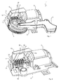
- FIG. 1 the essential components of the invention of an electric steering lock 1 for a motor vehicle are shown in a perspective view.
- the electric Steering lock 1 has a drive motor 2, a drive worm shaft 3 coupled to the drive motor 2 with a worm gear 6 and a drive wheel 4 coupled to the drive worm shaft 3, which in turn is motion-coupled to the lock pin 5, so that a drive movement of the drive worm shaft driven by the drive motor 2 3 leads to a movement of the locking pin 5.
- the drive motor 2 and the drive worm shaft 3 with the worm gear 6 define a drive unit 7 of the electric lock device 1 (see, for example FIG. 3 ), whose operation is known from the prior art, which is why a more detailed explanation of the function is dispensed with.
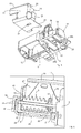
- the drive unit 7 is connected to a drive carrier 8 (see FIG. 4 ), which is formed by a plate-shaped structural element 9 and a stop element 10, such as in the Figures 2 . 3 and 4 can be seen in which was omitted for clarity on a representation of the drive wheel 4 and the locking pin 5.
- the plate-shaped structural element 9 has a receiving frame 11, which receives the drive motor 2 in a fixed position. On its side facing away from the drive worm shaft 3, the drive motor 2 is supported by a support extension 12 of the receiving frame 11.
- the receiving frame 11 has an interruption 14 (see, for example Figures 2 and 4 ), through which the drive screw shaft 2 coupled to the drive motor 2 extends therethrough.
- the plate-shaped structural element 9, in addition to the receiving frame 11 also has a bearing support 16, which is the free end 15 of the drive screw shaft 3, which FIG. 3 is visible, rotatably supports.
- the bearing support 16 has a vertically shaped shaft receptacle 17 (see, for example FIG.
- the drive unit 7 is inserted into the structural member 9 by the drive motor 2 are inserted into the receiving frame 11 under support on the support lug 12 and the free end 15 of the drive screw shaft 3 in the shaft receiving 17 of the bearing support 16 before then, inter alia, the stop element 10 is mounted.
- the stop element 10 which, for example, in detail in the FIGS. 4 and 5 has shown to restrict axial movement of the drive screw shaft 3 due to mechanical loads (in FIG. 2 the force direction is shown by way of example with reference to the arrow 20 for an unlocking process) a first stop surface 18 and a second stop surface 32, which extend substantially parallel to each other.
- the first stop surface 18 is in the assembled state of the stop element 10 on the structural element 9 (see Figures 1 and 2 ) between the receiving frame 11 and the bearing support 16 of the structural element 9.
- the first stop surface 18 in the region of lying between the screw shaft 6 and the drive motor 2 section 21 of the drive screw shaft 3, wherein the first stop surface 18 has a receiving recess 22 through which this section 21 of the drive screw shaft 3 extends therethrough.
- the receiving recess 22 of the first stop surface 18 extends in the mounted state of the electric steering lock 1 substantially parallel and horizontal to the plate-shaped structural element 9, so that a movement of the drive screw shaft 3 is perpendicular to the plate-shaped structural element 9 blocked by the first stop surface 18.
- the first stop surface 18 also blocks movement of the drive worm shaft 3 in a direction corresponding to the direction of the arrow 20 (see FIG FIG.
- the receiving recess 22 is minimally larger than the diameter of the drive screw shaft 3 dimensioned so that a movement of the screw helix 6 in the direction of the drive motor 2 are stopped by the first stop surface 18 at the latest would, at which the worm 6 then strikes and rests.
- the first abutment surface 18 thus axially supports the drive worm shaft 3 via the worm helix 6, the worm helix 6 being effected during the locking process and being subject to friction, which entails a loss of power. But also an axial movement of the screw helix 6 in the opposite direction, ie in the direction of the arrow 20 in FIG.
- the second stop surface 32 is blocked by this movement, the second stop surface 32 in the way. Because the stop surface 32 supports the drive screw shaft 3 axially over the free end 15 (see FIG. 3 ), wherein this system takes place during the unlocking process and is associated with lower friction and thus power losses than during the locking process.
- the second stop surface 32 blocks the axial movement of the free end 15 of the drive screw shaft 3, such as for example FIG. 3 or 6 is apparent.
- the worm gear 6 is thus arranged between the first and the second stop surface 18 and 32, so that an axial movement of the worm helix 6 by means of the stop element 10 is blocked in both axial directions.
- the stop element 10 also has a third stop surface 19. How out FIG. 6 It can be seen, a free end 15 having turning section 24 of the drive screw shaft 3 between the plate-shaped structural element 9 and the third stop surface 19 is arranged so that movement of the free end 15 of the drive screw shaft 3 from the shaft receiving 17 of the bearing support 16 out with the help of Third stop surface 19 is prevented by the third stop surface 19 blocks movement of the free end 15 of the drive screw shaft 3 in the direction perpendicular to the structural element 9. Consequently, the third stop surface 19 is formed in the manner of a radial stop and prevents movement of the free end 15 of the drive screw shaft 3 radially to the longitudinal extent of the bearing support 16 out.
- the third stop surface 19 is with respect to the longitudinal extent of the drive screw shaft 3 between the first stop surface 18th and the second stop surface 32, wherein the screw helix 6 between the first and third stop surface 18, 19 is arranged.
- the stop element 10 is - as can be seen from the foregoing - removably attached to the plate-shaped structural element 9. Like in FIG. 4 and 5 is shown, the stop element 10 is formed substantially in cross-section U-shaped with a first leg 25, a first leg opposite the second leg 26 and a first leg 25 with the second leg 26 connecting web 27. In the assembled state of the electric steering lock 1, the first leg 25 of the stop element 10 covers the drive worm shaft 3, which is arranged between the plate-shaped structural element 9 and the first leg 25 of the stop element 10. The first leg 25 of the
- U-shaped stop element 10 thus covers the drive worm shaft 3 to its side facing away from the plate-shaped structural element 9 side. Further, the web 27 of the stopper member 10 covers the drive worm shaft 3 laterally, such as in FIG. 2 can be seen. This covering and overlapping training serves to prevent theft and should prevent forcible access to the locking pin 5.
- the first stop surface 18 and / or the third stop surface 19 are integrally formed on the web 27 of the stop element 10 and extend substantially parallel to the first and second legs 25, 26. Further, the second stop surface 32 is integrally formed on the second leg 26 and extends into Direction of the first leg 25.
- the second leg 26 of the U-shaped stop member 10 is in the assembled state of the electric steering lock 1 on the side of the drive screw shaft 3 applied surface 28 (see FIG. 5 ) of the plate-shaped structural element 9.
- the second leg 26 has a greater longitudinal extent with respect to the first leg 25 and is detachably attached to the side surface 28 of the structural element 9 by means of latching means 29a, 29b and 30.
- latching means 29a, 29b and 30 To For this purpose, the second leg 26 of the stopper member 10 is pushed laterally along the side surface 28 of the structural element 9 and thereby passes between the two retaining arms 29a, 29b (as latching means) and the actual side surface 28.
- the second stop surface 32 which is arranged laterally from the third stop surface 19.
- the second stop surface 32 is laterally formed on the second leg 26 of the stop element 10 and extends parallel to the web 27 in the direction of the first leg 25.
- the third stop surface 19, however, is laterally formed on the web 27 and on a side edge of the web 27 and extends parallel to the second leg 26 and between the first and second legs 25, 26.
- the first stop surface 18 is formed on the other side edge of the web 27 and extends parallel to the second stop surface 32 between the first and second legs 25th , 26.
- the second stop surface 32 is arranged laterally on the side of the third stop surface 19, which faces away from the first stop surface 18.
- the second stop surface 32 is in the Figures 1 and 2 not to be recognized, since it in assembly of the stopper member 10 on the structural element 9 in a lateral slot 33 (see, for example FIG. 5 ) of the bearing support 16 is inserted, as in the sectional view of FIG. 6 can be seen.
- the second stop surface 32 forms an axial stop for the free end 15 of the drive screw shaft 3, so that the free end 15 in an unlocking operation with force and deflection action in the direction of arrow 20 in FIG. 2 abuts against the second stop surface 32 and a movement of the drive screw shaft 3 in the direction of the arrow 20 is stopped.
- the second stop surface 32 thus serves the axial movement limitation of Drive screw shaft 3 when the second stop surface 32 is inserted into the lateral slot 33 of the bearing support 16.
- the second stop surface 32 does not act directly on the structural element 9, when the drive screw shaft 3 moves or moves in a locking or unlocking in its axial direction, clamping teeth 35 are provided in the slot 33 of the bearing support 16, on the one hand, the second stop surface 32 in the slot 33, but also on the other hand, a deflection of the second stop surface 32 in the direction of the bearing support 16 buffer and dampen.
- the structural element 9 in the area of the drive worm shaft 3 has a reinforcing wall 36 serving to increase the mechanical strength, which has a passage opening 34 through which the first stop face 18 of the stop element 10 passes through in the assembled state of the electric steering lock 3 extends.
- the web 27 of the stop element 10 is located on the side facing away from the drive screw 3 side surface of the reinforcing wall 35 at this.
- the invention provides that the structural element 9 is made of a different material than the stop element 10. It makes sense to produce the structural element 9 made of plastic in a cost-effective injection molding process. On the other hand, an increased stability and reduced temperature sensitivity compared to the structural element 9 is required for the stop element 10, so that the stop element 10 is produced as a sheet metal part made of metal or a metal alloy, such as Zamak.
- the drive carrier 8 for a drive unit 7 is described above.
- the drive carrier 8 according to the invention is particularly suitable for an electric steering lock 1 and includes the structural element 9 with the receiving frame 11 which receives the drive motor 2 of the drive unit 7 fixed in position, and a bearing support 16, the free end 15 of the with the Drive motor 2 coupled drive screw shaft 3 rotatably supports.
- the stopper member 10 restricts the axial movement of the drive worm shaft 3 and includes at least the first stopper surface 18 and the second stopper surface 32. Further, the stopper member 10 is detachably attached to the plate-shaped structure member 9, the structure member 9 being made of a material other than the stopper member 10 is.
- the object according to the invention supports the drive screw shaft 3 in the axial direction or in the direction of the free end 15 (in the direction of the arrow 20 in FIG. 2 ) in the event that unlocks the electric steering lock, with little friction in this process is present.
- the support in the axial direction is in this case formed by the formed as a sheet metal bent stop element 10 and in particular on the second stop surface 32, wherein in the radial direction, ie pointing away from the structural element 9, the support is formed by the third stop surface 19. Further, the support is formed in the opposite axial direction of the first stop surface 18 when the electric steering lock 1 locks.
Abstract
Bei einem Antriebsträger (8) für eine Antriebseinheit (7), aufweisend ein plattenförmiges Strukturelement (9) mit einem Aufnahmerahmen (11), der einen Antriebsmotor (2) der Antriebseinheit (7) aufnehmen kann, und einer Lagerstütze (16), die das freie Ende (15) einer mit dem Antriebsmotor (2) gekoppelten Antriebsschneckenwelle (3) drehbar lagern kann, und ein Anschlagelement (10), welches zumindest eine axiale Bewegung der Antriebsschneckenwelle (3) einschränken kann, wobei das Anschlagelement (10) eine erste Anschlagfläche (18), welche zwischen dem Aufnahmerahmen (11) und der Lagerstütze (16) des Strukturelements (9) angeordnet ist, und eine zweite Anschlagfläche (19), welche nach Art eines Axialanschlags für das dem freien Ende (15) der Antriebsschneckenwelle (3) zugewandte Ende (23) der Schneckenwendel (6) dienend ausgebildet ist, aufweist, ist das Anschlagelement (10) aus Metall an dem plattenförmigen Strukturelement (9) aus Kunststoff demontierbar befestigt.In a drive carrier (8) for a drive unit (7), comprising a plate-shaped structural element (9) with a receiving frame (11), which can receive a drive motor (2) of the drive unit (7), and a bearing support (16), the free end (15) of a drive screw shaft (3) coupled to the drive motor (2) can be supported rotatably, and a stop element (10) which can restrict at least one axial movement of the drive worm shaft (3), wherein the stop element (10) has a first stop surface (18) which is arranged between the receiving frame (11) and the bearing support (16) of the structural element (9), and a second stop surface (19), which in the manner of an axial stop for the the end (23) of the screw helix (6) facing the drive screw shaft (3), the stop element (10) made of metal is detachably attached to the plate-shaped structural element (9) made of plastic.
Description
Die Erfindung richtet sich auf einen Antriebsträger für eine Antriebseinheit, insbesondere für eine elektrische Lenkverriegelung, aufweisend ein plattenförmiges Strukturelement mit einem Aufnahmerahmen, der einen Antriebsmotor der Antriebseinheit lagefest aufnehmen kann, und einer Lagerstütze, die das freie Ende einer mit dem Antriebsmotor gekoppelten Antriebsschneckenwelle drehbar lagern kann, und ein Anschlagelement, welches zumindest eine axiale Bewegung der Antriebsschneckenwelle einschränken kann, wobei das Anschlagelement eine erste Anschlagfläche, welche zwischen dem Aufnahmerahmen und der Lagerstützte des Strukturelements angeordnet ist, und eine zweite Anschlagfläche, welche nach Art eines Axialanschlags für das dem freien Ende der Antriebsschneckenwelle zugewandte Ende der Schneckenwendel dienend ausgebildet ist, aufweist.The invention is directed to a drive carrier for a drive unit, in particular for an electric steering lock, comprising a plate-shaped structural element with a receiving frame which can receive a drive motor of the drive unit fixed position, and a bearing support, which rotatably support the free end of a coupled to the drive motor drive screw shaft can, and a stopper member which can restrict at least one axial movement of the drive screw shaft, wherein the stopper member has a first stop surface which is disposed between the receiving frame and the bearing support of the structural member, and a second stop surface, which in the manner of an axial stop for the free end the drive screw shaft facing end of the screw helix is formed, has.
Ebenso richtet sich die vorliegende Erfindung auf eine elektrische Lenkverriegelung für ein Kraftfahrzeug, aufweisend eine Antriebseinheit, die einen Antriebsmotor und eine Antriebsschneckenwelle umfasst, ein mit der Antriebsschneckenwelle bewegungsgekoppeltes Antriebsrad und einen mit dem Antriebsrad verbundenen Sperrbolzen.Likewise, the present invention is directed to an electric steering lock for a motor vehicle, comprising a drive unit comprising a drive motor and a drive screw shaft, a driving wheel coupled to the drive screw shaft and a locking pin connected to the drive wheel.
Ein Antriebsträger und eine elektrische Lenkverriegelung der eingangs genannten Art sind zum Beispiel aus der
Der Erfindung liegt die Aufgabe zugrunde eine Lösung zu schaffen, die auf konstruktiv einfache Weise eine verbesserte Lenkverriegelung bereitstellt, die kostengünstig in ihrer Herstellung ist und ein hohes Maß an Funktionssicherheit aufweist.The invention has for its object to provide a solution that provides a structurally simple way improved steering lock, which is inexpensive to manufacture and has a high level of reliability.
Bei einem Antriebsträger der eingangs bezeichneten Art wird die Aufgabe erfindungsgemäß dadurch gelöst, dass das Anschlagelement an dem plattenförmigen Strukturelement demontierbar befestigt ist und dass das Strukturelement aus einem anderen Material als das Anschlagelement hergestellt ist.In a drive carrier of the type described above, the object is achieved in that the stop element is attached to the plate-shaped structural element removable and that the structural element is made of a different material than the stop element.
Ebenso wird die vorstehende Aufgabe bei einer elektrischen Lenkverriegelung der eingangs bezeichneten Art durch einen zumindest die Antriebseinheit tragenden Antriebsträger nach Anspruch 1 gelöst. Hierbei weist die erfindungsgemäße elektrische Lenkverriegelung den Antriebsträger auf, bei welchem der Aufnahmerahmen den Antriebsmotor der Antriebseinheit lagefest aufnimmt und bei dem die Lagerstütze das freie Ende der mit dem Antriebsmotor gekoppelten Antriebsschneckenwelle drehbar lagert, wobei das Anschlagelement eine axiale Bewegung der Antriebsschneckenwelle einschränkt. Die dritte Anschlagfläche des Anschlagelements kann in Verlängerung der Antriebsschneckenwelle hinter deren freien Ende angeordnet sein, so dass eine Auslenkung der Antriebsschneckenwelle in dieser Richtung verhindert wird.Likewise, the above object is achieved in an electric steering lock of the type described by an at least the drive unit supporting drive carrier according to claim 1. In this case, the electric steering lock according to the invention comprises the drive carrier, wherein the receiving frame rotatably receives the drive motor of the drive unit and in which the bearing support rotatably supports the free end of the coupled to the drive motor drive screw shaft, wherein the stop member limits an axial movement of the drive screw shaft. The third stop surface of the stop element may be arranged in extension of the drive worm shaft behind the free end, so that a deflection of the drive worm shaft is prevented in this direction.
Vorteilhafte und zweckmäßige Ausgestaltungen und Weiterbildungen der Erfindung ergeben sich aus den Unteransprüchen.Advantageous and expedient refinements and developments of the invention will become apparent from the dependent claims.
Durch die Erfindung werden ein Antriebsträger und eine elektrische Lenkverriegelung zur Verfügung gestellt, welche sich durch eine einfache, kompakte und preisgünstige Bauweise auszeichnen. Aufgrund des modularen Aufbaus des Antriebsträgers können das Strukturelement und das Anschlagelement entsprechend ihrer mechanischen Beanspruchung aus unterschiedlichen Materialien hergestellt sein, so dass das Strukturelement zum Beispiel kostengünstig im Spritzgussverfahren hergestellt ist, wohingegen für das Anschlagelement, welches wesentlich höheren Beanspruchungen Stand halten muss, ein aufwendigeres Herstellungsverfahren zum Einsatz kommt. Neben der mechanischen Belastung müssen bei der Materialauswahl Temperaturschwankungen berücksichtigt werden, wobei es unbedingt zu vermeiden ist, dass der für die Verriegelung und Entriegelung verantwortliche Teil des Antriebsträgers infolge sich ändernder Temperaturen derart verformt wird, dass die Funktionsweise beeinträchtigt ist. Darüber hinaus wird durch die Kombination unterschiedlicher und damit unterschiedlich schwerer Materialien insgesamt für den erfindungsgemäßen Antriebsträger und damit für die elektrische Lenkverriegelung eine vorteilhafte Gewichtsreduktion erzielt.By the invention, a drive carrier and an electric steering lock are provided, which is characterized by a simple, compact and inexpensive construction. Due to the modular structure of the drive carrier, the structural element and the stop element can be made of different materials according to their mechanical stress, so that the structural element is produced inexpensively by injection molding, for example, whereas for the stop element, which must withstand much higher stresses, a more complex manufacturing process is used. In addition to the mechanical load, temperature fluctuations must be taken into account in the material selection, whereby it is absolutely necessary to avoid that the part of the drive carrier responsible for the locking and unlocking is deformed as a result of changing temperatures in such a way that the functioning is impaired. In addition, an advantageous weight reduction is achieved by the combination of different materials and thus different heavy materials for the drive carrier according to the invention and thus for the electric steering lock.
Hinsichtlich der vorstehend angesprochenen Gewichtsreduktion ist es in Ausgestaltung der Erfindung von Vorteil, wenn das Strukturelement aus Kunststoff hergestellt ist und wenn das Anschlagelement aus Metall oder einer Metalllegierung hergestellt ist. Für das Strukturelement eignet sich aus Kostengründen ein thermoplastischer Kunststoff, wie zum Beispiel PBT, Polyamid, Polypropylen, Polycarbonat oder ein anderer geeigneter Kunststoff. Hingegen ist für das Anschlagelement ein Material mit einer hohen Festigkeit und mit gleichzeitig geringer Wärmeausdehnung erforderlich, so dass als Werkstoff beispielsweise eine Zinklegierung wie Zamak in Betracht kommt.With regard to the above-mentioned weight reduction, it is in an embodiment of the invention advantageous if the structural element is made of plastic and if the stop element is made of metal or a metal alloy. For reasons of cost, a thermoplastic material such as PBT, polyamide, polypropylene, polycarbonate or another suitable plastic is suitable for the structural element. By contrast, a material with a high strength and at the same time low thermal expansion is required for the stop element, so that as a material, for example, a zinc alloy such as Zamak comes into consideration.
Um die Bewegungsfreiheit des freien Wellenendes der Antriebsschneckenwelle in Radialrichtung - zur Gewährleistung der Funktionssicherheit des Antriebsträgers und damit der elektrischen Lenkverriegelung - einzugrenzen, sieht die Erfindung in weiterer Ausgestaltung vor, dass das Anschlagelement eine dritte Anschlagfläche aufweist, die nach Art eines Radialanschlags eine Bewegung des freien Endes der Antriebsschneckenwelle radial zu deren Längserstreckung verhindernd ausgebildet ist.To limit the freedom of movement of the free shaft end of the drive screw shaft in the radial direction - to ensure the reliability of the drive carrier and thus the electric steering lock, the invention provides in a further embodiment, that the stop element has a third stop surface, which in the manner of a radial stop movement of the free End of the Drive screw shaft is designed to prevent radial to the longitudinal extent.
Die axiale Bewegungsfreiheit der Schneckenwendel ist in vorteilhafter Ausgestaltung der Erfindung dadurch eingeschränkt, dass die dritte Anschlagfläche mit Bezug auf die Längserstreckung der Antriebsschneckenwelle zwischen der ersten Anschlagfläche und der zweiten Anschlagfläche angeordnet ist, wobei die Schneckenwendel zwischen der ersten und dritten Anschlagfläche angeordnet ist. Während der Antriebsmotor in dem Aufnahmerahmen des Strukturelements untergebracht ist und dort im Wesentlichen in Bezug auf das Strukturelement ohne Änderung seiner Lage, also lagefest, während seines Betriebs angeordnet ist, kann es infolge der mechanischen Kräfte beim Ent- und Verriegelung für die Antriebsschneckenwelle zu einer Verschiebung in Achsrichtung kommen, was jedoch durch das erfindungsgemäße Anschlagelement auf ein tolerierbares und verschwindend geringes Maß reduziert wird.The axial freedom of movement of the screw flight is limited in an advantageous embodiment of the invention in that the third stop surface is arranged with respect to the longitudinal extent of the drive screw shaft between the first stop surface and the second stop surface, wherein the screw spiral is disposed between the first and third stop surface. While the drive motor is housed in the receiving frame of the structural element and is arranged there substantially in relation to the structural element without changing its position, that is fixed in position during its operation, it can due to the mechanical forces during unlocking and locking for the drive screw shaft to a shift come in the axial direction, but this is reduced by the stop element according to the invention to a tolerable and negligible degree.
Zur Erhöhung der Kompaktheit des Antriebsträgers und zur Minimierung seines Einbauraumes sieht die Erfindung in Ausgestaltung vor, dass die Lagerstütze einen seitlichen Schlitz aufweist, in welchen die zweite Anschlagfläche des Anschlagelements zur axialen Bewegungsbegrenzung der Antriebsschneckenwelle eingeschoben ist.To increase the compactness of the drive carrier and to minimize its installation space, the invention provides in an embodiment that the bearing support has a lateral slot in which the second stop surface of the stop element is inserted for axial movement limitation of the drive screw shaft.
Die Funktionalität des Anschlagelements kann dadurch erhöht werden, wenn das Anschlagelement im Wesentlichen U-förmig mit einem ersten Schenkel, einem dem ersten Schenkel gegenüberliegenden zweiten Schenkel und einem den ersten Schenkel mit dem zweiten Schenkel verbindenden Steg ausgebildet ist, wobei der erste Schenkel des U-förmigen Anschlagelements die Antriebsschneckenwelle zu der dem plattenförmigen Strukturelement abgewandten Seite überdeckt. Dabei deckt der Steg, welcher die beiden Schenkel des U-förmigen Anschlagelements miteinander verbindet, den seitlichen Bereich der Antriebsschneckenwelle ab, so dass zusätzlich zu der Bewegungsbegrenzung der Antriebsschneckenwelle diese auch gegenüber einem gewaltsamen Zugriff geschützt ist, wodurch das Anschlagelement infolge seiner die Antriebsschneckenwelle überdeckenden Ausbildung einen Diebstahlschutz bereitstellt.The functionality of the stop element can be increased if the stop element is substantially U-shaped with a first leg, a second leg opposite the first leg and a web connecting the first leg with the second leg, wherein the first leg of the U-shaped shaped stop element covers the drive screw shaft to the side facing away from the plate-shaped structural element. In this case, covers the web, which connects the two legs of the U-shaped stop element together, the lateral region of the drive worm shaft, so that in addition to the movement limitation of the drive worm shaft this is also protected against a violent access, whereby the stop element as a result of his Drive screw shaft covering training provides a theft protection.
Zur einfachen und schnellen Anbringung und Demontage des Anschlagelements an und von dem Strukturelement sieht die Erfindung ferner vor, dass der zweite Schenkel des U-förmigen Anschlagelements auf der der Antriebsschneckenwelle abgewandten Seitenfläche des plattenförmigen Strukturelements angeordnet ist und dort mit Hilfe von Rastmitteln mit dem Strukturelement in Eingriff steht. Der erste Schenkel erstreckt sich hierbei parallel zu dem zweiten Schenkel. Durch diese Anordnung des U-förmigen Anschlagelements und des Strukturelements ist die Antriebsschneckenwelle an drei Seiten überdeckt und damit vor einem unerwünschten Zugriff von außen geschützt.For a simple and quick attachment and dismounting of the stop element to and from the structural element, the invention further provides that the second leg of the U-shaped stop element is arranged on the side facing away from the drive screw shaft side surface of the plate-shaped structural element and there by means of locking means with the structural element in Intervention is. The first leg extends parallel to the second leg. This arrangement of the U-shaped stop element and the structural element, the drive screw shaft is covered on three sides and thus protected against unwanted access from the outside.
Hinsichtlich einer kompakten Bauform des Antriebsträgers ist es von besonderem Vorteil, wenn die erste Anschlagfläche und/oder die dritte Anschlagfläche am Steg des Anschlagelements angeformt sind und sich im Wesentlichen parallel zum ersten und zweiten Schenkel erstrecken. Ebenso führt es zu einer kompakten Bauform, wenn die zweite Anschlagfläche an dem zweiten Schenkel angeformt ist und sich in Richtung des ersten Schenkels erstreckt.With regard to a compact design of the drive carrier, it is particularly advantageous if the first stop surface and / or the third stop surface are integrally formed on the web of the stop element and extend substantially parallel to the first and second legs. Likewise, it leads to a compact design, when the second stop surface is integrally formed on the second leg and extends in the direction of the first leg.
In weiterer Ausgestaltung der erfindungsgemäßen elektrischen Lenkverriegelung und des Antriebsträgers ist vorgesehen, dass die erste Anschlagfläche des Anschlagelements eine im Wesentlichen parallel zum plattenförmigen Strukturelement verlaufende und eine Bewegung der Antriebsschneckenwelle senkrecht zum plattenförmigen Strukturelement blockierende Aufnahmeausnehmung aufweist, in welche ein zwischen der Schneckenwendel und dem Antriebsmotor liegender Abschnitt der Antriebsschneckenwelle angeordnet ist. Die Aufnahmeausnehmung dient im normalen Betrieb lediglich als eine Art Führung oder Abstützung, wohingegen sie bei Belastung und Auslenkung der Antriebsschneckenwelle eine Bewegung der Welle in Richtung des Antriebsmotors und in eine Richtung quer zum Strukturelement verhindert.In a further embodiment of the electric steering lock and the drive carrier according to the invention it is provided that the first stop surface of the stop element has a substantially parallel to the plate-shaped structural element and a movement of the drive screw shaft perpendicular to the plate-shaped structural element blocking receiving recess, in which a lying between the screw helix and the drive motor Section of the drive screw shaft is arranged. The receiving recess serves in normal operation only as a kind of guide or support, whereas it prevents movement of the shaft in the direction of the drive motor and in a direction transverse to the structural element under load and deflection of the drive screw shaft.
Schließlich sieht die Erfindung in weiterer Ausgestaltung vor, dass ein das freie Ende aufweisender wendelfreier Abschnitt der Antriebsschneckenwelle zwischen dem plattenförmigen Strukturelement und der dritten Anschlagfläche angeordnet ist, so dass eine Bewegung des freien Endes der Antriebsschneckenwelle aus der Lagerstütze heraus mit Hilfe der dritten Anschlagfläche blockiert ist. Die dritte Anschlagfläche dient somit dazu, eine eine Bewegung quer zum Strukturelement und von diesem fort, d.h. eine Bewegung aus der Lagerstützte heraus - zu verhindern. Dabei erstreckt sich die dritte Anschlagfläche parallel zu der ersten Anschlagfläche, wobei beide Anschlagflächen (erste und dritte) parallel zu dem Strukturelement verlaufend ausgebildet sind.Finally, the invention provides, in a further embodiment, that a helical section having the free end the drive screw shaft between the plate-shaped structural element and the third stop surface is arranged, so that a movement of the free end of the drive screw shaft is blocked out of the bearing support by means of the third stop surface. The third abutment surface thus serves to prevent movement across and away from the structural member, ie, movement out of the bearing support. In this case, the third stop surface extends parallel to the first stop surface, wherein both stop surfaces (first and third) are formed to extend parallel to the structural element.
Es versteht sich, dass die vorstehend genannten und nachstehend noch zu erläuternden Merkmale nicht nur in der jeweils angegebenen Kombination, sondern auch in anderen Kombinationen oder in Alleinstellung verwendbar sind, ohne den Rahmen der vorliegenden Erfindung zu verlassen. Der Rahmen der Erfindung ist nur durch die Ansprüche definiert.It is understood that the features mentioned above and those yet to be explained can be used not only in the particular combination given, but also in other combinations or in isolation, without departing from the scope of the present invention. The scope of the invention is defined only by the claims.
Weitere Einzelheiten, Merkmale und Vorteile des Gegenstandes der Erfindung ergeben sich aus der nachfolgenden Beschreibung im Zusammenhang mit der Zeichnung, in der beispielhaft ein bevorzugtes Ausführungsbeispiel der Erfindung dargestellt ist. In der Zeichnung zeigt:
-
Figur 1 in perspektivischer Ansicht eine elektrische Lenkungsverriegelung mit ihren wichtigsten Bauteilen, -
Figur 2 -
Figur 3 -
Figur 4 -
Figur 5 -
Figur 6
-
FIG. 1 in perspective view an electric steering lock with its main components, -
FIG. 2 a perspective view of a drive unit carrying drive carrier of the electric steering lock, -
FIG. 3 the drive unit in perspective view, -
FIG. 4 the drive carrier in a perspective detail view, -
FIG. 5 the drive carrier in a further perspective single part illustration and -
FIG. 6 a sectional view of the drive carrier and drive unit.
In
Wie aus den
Das Anschlagelement 10, welches zum Beispiel im Detail in den
Das Anschlagelement 10 weist darüber hinaus eine dritte Anschlagfläche 19 auf. Wie aus
Das Anschlagelement 10 ist - wie aus den vorstehenden Ausführungen ersichtlich sein sollte - an dem plattenförmigen Strukturelement 9 demontierbar befestigt. Wie zum Beispiel in
U-förmigen Anschlagelements 10 überdeckt somit die Antriebsschneckenwelle 3 zu ihrer dem plattenförmigen Strukturelement 9 abgewandten Seite. Ferner deckt der Steg 27 des Anschlagelements 10 die Antriebsschneckenwelle 3 seitlich ab, wie zum Beispiel in
Der zweite Schenkel 26 des U-förmigen Anschlagelements 10 ist im zusammengebauten Zustand der elektrischen Lenkverriegelung 1 auf der der Antriebsschneckenwelle 3 angewandten Seitenfläche 28 (siehe
Neben der ersten und dritten Anschlagfläche 18, 19 weist das Anschlagelement 10 die zweite Anschlagfläche 32 auf, die seitlich von der dritten Anschlagfläche 19 angeordnet ist. Die zweite Anschlagfläche 32 ist seitlich an dem zweiten Schenkel 26 des Anschlagelements 10 angeformt und erstreckt sich parallel zu dem Steg 27 in Richtung des ersten Schenkels 25. Die dritte Anschlagfläche 19 ist hingegen seitlich an dem Steg 27 bzw. an einem Seitenrand des Stegs 27 angeformt und erstreckt sich parallel zu dem zweiten Schenkel 26 sowie zwischen dem ersten und zweiten Schenkel 25, 26. Ferner ist die erste Anschlagfläche 18 an dem anderen Seitenrand des Stegs 27 angeformt und erstreckt sich parallel zu der zweiten Anschlagfläche 32 zwischen dem ersten und zweiten Schenkel 25, 26.In addition to the first and third stop surfaces 18, 19, the
Wie zuvor ausgeführt, ist die zweite Anschlagfläche 32 seitlich auf der Seite der dritten Anschlagfläche 19 angeordnet, die der ersten Anschlagfläche 18 abgewandt ist. Die zweite Anschlagfläche 32 ist in den
Es sei noch angemerkt, dass das Strukturelement 9 im Bereich der Antriebsschneckenwelle 3 eine zur Erhöhung der mechanischen Festigkeit dienende Verstärkungswandung 36 aufweist, die über eine Durchgangsöffnung 34 verfügt, durch die sich im zusammengebauten Zustand der elektrischen Lenkverriegelung 3 die erste Anschlagfläche 18 des Anschlagelements 10 hindurch erstreckt. Der Steg 27 des Anschlagelements 10 liegt an der der Antriebsschnecke 3 abgewandten Seitenfläche der Verstärkungswandung 35 an dieser an.It should also be noted that the
Zur Reduzierung des Gesamtgewichts der elektrischen Lenkverriegelung und zur Senkung der Materialkosten ist erfindungsgemäß vorgesehen, dass das Strukturelement 9 aus einem anderen Material als das Anschlagelement 10 hergestellt ist. Es bietet sich an, das Strukturelement 9 aus Kunststoff in einem kostengünstigen Spritzgussverfahren herzustellen. Demgegenüber ist für das Anschlagelement 10 eine im Vergleich zu dem Strukturelement 9 erhöhte Stabilität und verringerte Temperaturempfindlichkeit gefordert, so dass das Anschlagelement 10 als Blechteil aus Metall oder einer Metalllegierung, wie zum Beispiel Zamak, hergestellt ist.To reduce the total weight of the electric steering lock and to reduce the material costs, the invention provides that the
Zusammengefasst ist vorstehend ein erfindungsgemäßer Antriebsträger 8 für eine Antriebseinheit 7 beschrieben. Der erfindungsgemäße Antriebsträger 8 ist insbesondere für eine elektrische Lenkverriegelung 1 verwendbar und umfasst das Strukturelement 9 mit dem Aufnahmerahmen 11, der den Antriebsmotor 2 der Antriebseinheit 7 lagefest aufnimmt, und einer Lagerstütze 16, die das freie Ende 15 der mit dem Antriebsmotor 2 gekoppelten Antriebsschneckenwelle 3 drehbar lagert. Das Anschlagelement 10 schränkt die axiale Bewegung der Antriebsschneckenwelle 3 ein und umfasst zumindest die erste Anschlagfläche 18 und die zweite Anschlagfläche 32. Ferner ist das Anschlagelement 10 an dem plattenförmigen Strukturelement 9 demontierbar befestigt, wobei das Strukturelement 9 aus einem anderen Material als das Anschlagelement 10 hergestellt ist.In summary, an
Der erfindungsgemäße Gegenstand stützt die Antriebsschneckenwelle 3 in axialer Richtung bzw. in Richtung des freien Endes 15 (in Richtung des Pfeils 20 in
Die vorstehend beschriebene Erfindung ist selbstverständlich nicht auf die beschriebene und dargestellte Ausführungsform beschränkt. Es ist ersichtlich, dass an der in der Zeichnung dargestellten Ausführungsform zahlreiche, dem Fachmann entsprechend der beabsichtigten Anwendung naheliegende Abänderungen vorgenommen werden können, ohne dass dadurch der Bereich der Erfindung verlassen wird. Dabei gehört zur Erfindung alles dasjenige, was in der Beschreibung enthalten und/oder in der Zeichnung dargestellt ist, einschließlich dessen, was abweichend von dem konkreten Ausführungsbeispiel für den Fachmann naheliegt.Of course, the invention described above is not limited to the described and illustrated embodiment. It will be appreciated that numerous modifications which are obvious to a person skilled in the art according to the intended application can be made to the embodiment shown in the drawing without departing from the scope of the invention. It belongs to the invention, all that which is contained in the description and / or shown in the drawing, including what, in deviation from the concrete embodiment obvious to those skilled.
Claims (12)
ein plattenförmiges Strukturelement (9) mit einem Aufnahmerahmen (11), der einen Antriebsmotor (2) der Antriebseinheit (7) lagefest aufnehmen kann, und einer Lagerstütze (16), die das freie Ende (15) einer mit dem Antriebsmotor (2) gekoppelten Antriebsschneckenwelle (3) drehbar lagern kann, und
ein Anschlagelement (10), welches zumindest eine axiale Bewegung der Antriebsschneckenwelle (3) einschränken kann,
wobei das Anschlagelement (10) eine erste Anschlagfläche (18), welche zwischen dem Aufnahmerahmen (11) und der Lagerstützte (16) des Strukturelements (9) angeordnet ist, und eine zweite Anschlagfläche (32), welche nach Art eines Axialanschlags für das dem freien Ende (15) der Antriebsschneckenwelle (3) zugewandte Ende (23) der Schneckenwendel (6) dienend ausgebildet ist, aufweist,
dadurch gekennzeichnet, dass das Anschlagelement (10) an dem plattenförmigen Strukturelement (9) demontierbar befestigt ist und dass das Strukturelement (9) aus einem anderen Material als das Anschlagelement (10) hergestellt ist.Drive carrier (8) for a drive unit (7), in particular for an electric steering lock (1), comprising
a plate-shaped structural element (9) with a receiving frame (11) which can receive a drive motor (2) of the drive unit (7) fixed position, and a bearing support (16), the free end (15) coupled to the drive motor (2) Drive screw shaft (3) can be stored rotatably, and
a stop element (10) which can restrict at least one axial movement of the drive worm shaft (3),
wherein the stop element (10) has a first stop surface (18) which is arranged between the receiving frame (11) and the bearing support (16) of the structural element (9), and a second stop surface (32), which in the manner of an axial stop for the free end (15) of the drive screw shaft (3) facing the end (23) of the screw helix (6) is formed serving,
characterized in that the stopper member (10) is detachably secured to the plate-shaped structural member (9) and that the structural member (9) is made of a different material than the stopper member (10).
gekennzeichnet durch einen zumindest die Antriebseinheit (7) tragenden Antriebsträger (8) nach Anspruch 1.An electric steering lock (1) for a motor vehicle, comprising a drive unit (7) comprising a drive motor (2) and a drive worm shaft (3), a drive wheel (4) coupled to the drive worm shaft (3) and a drive wheel (4). connected locking pin (5),
characterized by an at least the drive unit (7) carrying drive carrier (8) according to claim 1.
dadurch gekennzeichnet, dass der zweite Schenkel (26) des U-förmigen Anschlagelements (10) auf der der Antriebsschneckenwelle (3) abgewandten Seitenfläche (28) des plattenförmigen Strukturelements (9) angeordnet ist und dort mit Hilfe von Rastmitteln (29a, 29b, 30, 31) mit dem Strukturelement (9) in Eingriff steht.Electric steering lock (1) according to claim 7,
characterized in that the second leg (26) of the U-shaped stop element (10) on the drive screw shaft (3) facing away from side surface (28) of the plate-shaped structural element (9) is arranged there and with the aid of locking means (29a, 29b, 30 , 31) is in engagement with the structural element (9).
Applications Claiming Priority (1)
| Application Number | Priority Date | Filing Date | Title |
|---|---|---|---|
| DE102013114788.7A DE102013114788A1 (en) | 2013-12-23 | 2013-12-23 | Drive carrier for a drive unit and electric steering lock with such a drive carrier |
Publications (2)
| Publication Number | Publication Date |
|---|---|
| EP2886402A1 true EP2886402A1 (en) | 2015-06-24 |
| EP2886402B1 EP2886402B1 (en) | 2016-06-29 |
Family
ID=52011007
Family Applications (1)
| Application Number | Title | Priority Date | Filing Date |
|---|---|---|---|
| EP14194275.5A Not-in-force EP2886402B1 (en) | 2013-12-23 | 2014-11-21 | Drive mount for a drive unit, and electrical steering lock with such a drive mount |
Country Status (3)
| Country | Link |
|---|---|
| EP (1) | EP2886402B1 (en) |
| CN (1) | CN104724050B (en) |
| DE (1) | DE102013114788A1 (en) |
Cited By (1)
| Publication number | Priority date | Publication date | Assignee | Title |
|---|---|---|---|---|
| JP2020066385A (en) * | 2018-10-26 | 2020-04-30 | 株式会社ユーシン | Electric steering lock device |
Citations (5)
| Publication number | Priority date | Publication date | Assignee | Title |
|---|---|---|---|---|
| US20020088257A1 (en) * | 2001-01-09 | 2002-07-11 | Dimig Steven J. | Steering column lock apparatus and method |
| DE10109609C1 (en) | 2001-02-28 | 2002-10-10 | Huf Huelsbeck & Fuerst Gmbh | Lock, in particular for locking the steering spindle of a motor vehicle |
| US20060053921A1 (en) * | 2004-08-26 | 2006-03-16 | Jidosha Denki Kogyo Co., Ltd. | Actuator apparatus |
| US20100083716A1 (en) * | 2008-10-03 | 2010-04-08 | Kabushiki Kaisha Tokai Rika Denki Seisakusho | Electric steering wheel lock device and motor damping structure |
| DE102011120015A1 (en) * | 2011-12-02 | 2012-06-14 | Daimler Ag | Electric steering lock device of vehicle, has locking bolt and guide shaft of housing base made of lightweight material, where bolt and sliding faces of guide shaft are made of hard-wear material corresponding to specific lubricity |
Family Cites Families (2)
| Publication number | Priority date | Publication date | Assignee | Title |
|---|---|---|---|---|
| JP4394534B2 (en) * | 2004-07-29 | 2010-01-06 | 株式会社東海理化電機製作所 | Steering lock device |
| JP2007230350A (en) * | 2006-02-28 | 2007-09-13 | Alpha Corp | Electric steering lock device |
-
2013
- 2013-12-23 DE DE102013114788.7A patent/DE102013114788A1/en not_active Withdrawn
-
2014
- 2014-11-21 EP EP14194275.5A patent/EP2886402B1/en not_active Not-in-force
- 2014-12-08 CN CN201410745306.XA patent/CN104724050B/en active Active
Patent Citations (5)
| Publication number | Priority date | Publication date | Assignee | Title |
|---|---|---|---|---|
| US20020088257A1 (en) * | 2001-01-09 | 2002-07-11 | Dimig Steven J. | Steering column lock apparatus and method |
| DE10109609C1 (en) | 2001-02-28 | 2002-10-10 | Huf Huelsbeck & Fuerst Gmbh | Lock, in particular for locking the steering spindle of a motor vehicle |
| US20060053921A1 (en) * | 2004-08-26 | 2006-03-16 | Jidosha Denki Kogyo Co., Ltd. | Actuator apparatus |
| US20100083716A1 (en) * | 2008-10-03 | 2010-04-08 | Kabushiki Kaisha Tokai Rika Denki Seisakusho | Electric steering wheel lock device and motor damping structure |
| DE102011120015A1 (en) * | 2011-12-02 | 2012-06-14 | Daimler Ag | Electric steering lock device of vehicle, has locking bolt and guide shaft of housing base made of lightweight material, where bolt and sliding faces of guide shaft are made of hard-wear material corresponding to specific lubricity |
Cited By (1)
| Publication number | Priority date | Publication date | Assignee | Title |
|---|---|---|---|---|
| JP2020066385A (en) * | 2018-10-26 | 2020-04-30 | 株式会社ユーシン | Electric steering lock device |
Also Published As
| Publication number | Publication date |
|---|---|
| CN104724050B (en) | 2019-03-08 |
| DE102013114788A1 (en) | 2015-06-25 |
| EP2886402B1 (en) | 2016-06-29 |
| CN104724050A (en) | 2015-06-24 |
Similar Documents
| Publication | Publication Date | Title |
|---|---|---|
| EP0175996B1 (en) | Drive unit particularly for moving window screens, gliding roofs, seats and similar vehicle devices | |
| EP1735194B1 (en) | Windshield wiper, especially for a motor vehicle | |
| DE19861100A1 (en) | Spindle or worm drive for adjusting mechanisms in motor vehicles has push-in connections for plates forming housing of mechanism and constructed as supporting connection points taking gearing forces | |
| EP3304655B1 (en) | Locking system for a charging plug | |
| DE102008040877A1 (en) | Device for use in steering system of vehicle for locking steering, has locking unit, which is arranged on low momentum side of steering system, where locking unit has spring element | |
| EP2572945B1 (en) | Electric steering lock | |
| DE102008059827B4 (en) | Sliding shoe for a switching element of a switching device and switching element with such a sliding shoe | |
| DE19861273B4 (en) | Spindle or worm drive for adjusting devices in motor vehicles | |
| DE102018100458A1 (en) | Transmission housing unit and gear unit with wedge-shaped compensation element for axial play compensation | |
| DE3744274C2 (en) | Electric motor, especially small electric motor | |
| DE102012109488B4 (en) | Compact warehouse with multi-part frame made of extruded sections | |
| EP2886402B1 (en) | Drive mount for a drive unit, and electrical steering lock with such a drive mount | |
| DE102008028371A1 (en) | Tolerance ring for bypassing radial distance between roller bearing and steering shaft of motor vehicle, has spring and groove provided for controlling mutual relative movement of components in axial direction and/or radial directions | |
| DE102021209478B4 (en) | Belt retractor for a seat belt | |
| EP3575637B1 (en) | Motor vehicle drive assembly | |
| DE102017214017A1 (en) | Device for pressing a rack | |
| DE19861278B4 (en) | Spindle or worm drive for adjusting mechanisms in motor vehicles has push-in connections for plates forming housing of mechanism and constructed as supporting connection points taking gearing forces | |
| DE102019133406A1 (en) | Push rod guide assembly, steering actuator and method for manufacturing a push rod guide assembly | |
| WO2016192716A1 (en) | Motor vehicle lock | |
| EP1245763B1 (en) | Electric motor actuator for motor vehicles, especially for central locking devices | |
| DE202006019194U1 (en) | Gear unit of an adjustment and housing of such a gear unit | |
| DE102019215478A1 (en) | Electromechanical steering system for a motor vehicle and method for assembling an electromechanical steering system | |
| DE102007003635B4 (en) | Devices for connecting a first part to a carrier | |
| DE102013102555A1 (en) | wiper motor | |
| EP3741933B1 (en) | Locking device |
Legal Events
| Date | Code | Title | Description |
|---|---|---|---|
| PUAI | Public reference made under article 153(3) epc to a published international application that has entered the european phase |
Free format text: ORIGINAL CODE: 0009012 |
|
| 17P | Request for examination filed |
Effective date: 20141121 |
|
| AK | Designated contracting states |
Kind code of ref document: A1 Designated state(s): AL AT BE BG CH CY CZ DE DK EE ES FI FR GB GR HR HU IE IS IT LI LT LU LV MC MK MT NL NO PL PT RO RS SE SI SK SM TR |
|
| AX | Request for extension of the european patent |
Extension state: BA ME |
|
| R17P | Request for examination filed (corrected) |
Effective date: 20160104 |
|
| RBV | Designated contracting states (corrected) |
Designated state(s): AL AT BE BG CH CY CZ DE DK EE ES FI FR GB GR HR HU IE IS IT LI LT LU LV MC MK MT NL NO PL PT RO RS SE SI SK SM TR |
|
| GRAP | Despatch of communication of intention to grant a patent |
Free format text: ORIGINAL CODE: EPIDOSNIGR1 |
|
| INTG | Intention to grant announced |
Effective date: 20160315 |
|
| GRAS | Grant fee paid |
Free format text: ORIGINAL CODE: EPIDOSNIGR3 |
|
| GRAA | (expected) grant |
Free format text: ORIGINAL CODE: 0009210 |
|
| AK | Designated contracting states |
Kind code of ref document: B1 Designated state(s): AL AT BE BG CH CY CZ DE DK EE ES FI FR GB GR HR HU IE IS IT LI LT LU LV MC MK MT NL NO PL PT RO RS SE SI SK SM TR |
|
| REG | Reference to a national code |
Ref country code: GB Ref legal event code: FG4D Free format text: NOT ENGLISH |
|
| REG | Reference to a national code |
Ref country code: CH Ref legal event code: EP |
|
| REG | Reference to a national code |
Ref country code: AT Ref legal event code: REF Ref document number: 808831 Country of ref document: AT Kind code of ref document: T Effective date: 20160715 |
|
| REG | Reference to a national code |
Ref country code: IE Ref legal event code: FG4D Free format text: LANGUAGE OF EP DOCUMENT: GERMAN |
|
| REG | Reference to a national code |
Ref country code: DE Ref legal event code: R096 Ref document number: 502014001015 Country of ref document: DE |
|
| REG | Reference to a national code |
Ref country code: LT Ref legal event code: MG4D |
|
| PG25 | Lapsed in a contracting state [announced via postgrant information from national office to epo] |
Ref country code: FI Free format text: LAPSE BECAUSE OF FAILURE TO SUBMIT A TRANSLATION OF THE DESCRIPTION OR TO PAY THE FEE WITHIN THE PRESCRIBED TIME-LIMIT Effective date: 20160629 Ref country code: NO Free format text: LAPSE BECAUSE OF FAILURE TO SUBMIT A TRANSLATION OF THE DESCRIPTION OR TO PAY THE FEE WITHIN THE PRESCRIBED TIME-LIMIT Effective date: 20160929 Ref country code: LT Free format text: LAPSE BECAUSE OF FAILURE TO SUBMIT A TRANSLATION OF THE DESCRIPTION OR TO PAY THE FEE WITHIN THE PRESCRIBED TIME-LIMIT Effective date: 20160629 |
|
| REG | Reference to a national code |
Ref country code: NL Ref legal event code: MP Effective date: 20160629 |
|
| PG25 | Lapsed in a contracting state [announced via postgrant information from national office to epo] |
Ref country code: HR Free format text: LAPSE BECAUSE OF FAILURE TO SUBMIT A TRANSLATION OF THE DESCRIPTION OR TO PAY THE FEE WITHIN THE PRESCRIBED TIME-LIMIT Effective date: 20160629 Ref country code: RS Free format text: LAPSE BECAUSE OF FAILURE TO SUBMIT A TRANSLATION OF THE DESCRIPTION OR TO PAY THE FEE WITHIN THE PRESCRIBED TIME-LIMIT Effective date: 20160629 Ref country code: SE Free format text: LAPSE BECAUSE OF FAILURE TO SUBMIT A TRANSLATION OF THE DESCRIPTION OR TO PAY THE FEE WITHIN THE PRESCRIBED TIME-LIMIT Effective date: 20160629 Ref country code: LV Free format text: LAPSE BECAUSE OF FAILURE TO SUBMIT A TRANSLATION OF THE DESCRIPTION OR TO PAY THE FEE WITHIN THE PRESCRIBED TIME-LIMIT Effective date: 20160629 Ref country code: NL Free format text: LAPSE BECAUSE OF FAILURE TO SUBMIT A TRANSLATION OF THE DESCRIPTION OR TO PAY THE FEE WITHIN THE PRESCRIBED TIME-LIMIT Effective date: 20160629 Ref country code: GR Free format text: LAPSE BECAUSE OF FAILURE TO SUBMIT A TRANSLATION OF THE DESCRIPTION OR TO PAY THE FEE WITHIN THE PRESCRIBED TIME-LIMIT Effective date: 20160930 |
|
| PG25 | Lapsed in a contracting state [announced via postgrant information from national office to epo] |
Ref country code: EE Free format text: LAPSE BECAUSE OF FAILURE TO SUBMIT A TRANSLATION OF THE DESCRIPTION OR TO PAY THE FEE WITHIN THE PRESCRIBED TIME-LIMIT Effective date: 20160629 Ref country code: SK Free format text: LAPSE BECAUSE OF FAILURE TO SUBMIT A TRANSLATION OF THE DESCRIPTION OR TO PAY THE FEE WITHIN THE PRESCRIBED TIME-LIMIT Effective date: 20160629 Ref country code: IT Free format text: LAPSE BECAUSE OF FAILURE TO SUBMIT A TRANSLATION OF THE DESCRIPTION OR TO PAY THE FEE WITHIN THE PRESCRIBED TIME-LIMIT Effective date: 20160629 Ref country code: CZ Free format text: LAPSE BECAUSE OF FAILURE TO SUBMIT A TRANSLATION OF THE DESCRIPTION OR TO PAY THE FEE WITHIN THE PRESCRIBED TIME-LIMIT Effective date: 20160629 Ref country code: IS Free format text: LAPSE BECAUSE OF FAILURE TO SUBMIT A TRANSLATION OF THE DESCRIPTION OR TO PAY THE FEE WITHIN THE PRESCRIBED TIME-LIMIT Effective date: 20161029 Ref country code: RO Free format text: LAPSE BECAUSE OF FAILURE TO SUBMIT A TRANSLATION OF THE DESCRIPTION OR TO PAY THE FEE WITHIN THE PRESCRIBED TIME-LIMIT Effective date: 20160629 |
|
| PG25 | Lapsed in a contracting state [announced via postgrant information from national office to epo] |
Ref country code: PT Free format text: LAPSE BECAUSE OF FAILURE TO SUBMIT A TRANSLATION OF THE DESCRIPTION OR TO PAY THE FEE WITHIN THE PRESCRIBED TIME-LIMIT Effective date: 20161031 Ref country code: PL Free format text: LAPSE BECAUSE OF FAILURE TO SUBMIT A TRANSLATION OF THE DESCRIPTION OR TO PAY THE FEE WITHIN THE PRESCRIBED TIME-LIMIT Effective date: 20160629 Ref country code: SM Free format text: LAPSE BECAUSE OF FAILURE TO SUBMIT A TRANSLATION OF THE DESCRIPTION OR TO PAY THE FEE WITHIN THE PRESCRIBED TIME-LIMIT Effective date: 20160629 Ref country code: ES Free format text: LAPSE BECAUSE OF FAILURE TO SUBMIT A TRANSLATION OF THE DESCRIPTION OR TO PAY THE FEE WITHIN THE PRESCRIBED TIME-LIMIT Effective date: 20160629 Ref country code: BE Free format text: LAPSE BECAUSE OF NON-PAYMENT OF DUE FEES Effective date: 20161130 |
|
| REG | Reference to a national code |
Ref country code: FR Ref legal event code: PLFP Year of fee payment: 3 |
|
| REG | Reference to a national code |
Ref country code: DE Ref legal event code: R097 Ref document number: 502014001015 Country of ref document: DE |
|
| PG25 | Lapsed in a contracting state [announced via postgrant information from national office to epo] |
Ref country code: DK Free format text: LAPSE BECAUSE OF FAILURE TO SUBMIT A TRANSLATION OF THE DESCRIPTION OR TO PAY THE FEE WITHIN THE PRESCRIBED TIME-LIMIT Effective date: 20160629 |
|
| 26N | No opposition filed |
Effective date: 20170330 |
|
| PLBE | No opposition filed within time limit |
Free format text: ORIGINAL CODE: 0009261 |
|
| STAA | Information on the status of an ep patent application or granted ep patent |
Free format text: STATUS: NO OPPOSITION FILED WITHIN TIME LIMIT |
|
| REG | Reference to a national code |
Ref country code: IE Ref legal event code: MM4A |
|
| PG25 | Lapsed in a contracting state [announced via postgrant information from national office to epo] |
Ref country code: SI Free format text: LAPSE BECAUSE OF FAILURE TO SUBMIT A TRANSLATION OF THE DESCRIPTION OR TO PAY THE FEE WITHIN THE PRESCRIBED TIME-LIMIT Effective date: 20160629 Ref country code: BG Free format text: LAPSE BECAUSE OF FAILURE TO SUBMIT A TRANSLATION OF THE DESCRIPTION OR TO PAY THE FEE WITHIN THE PRESCRIBED TIME-LIMIT Effective date: 20160929 |
|
| PG25 | Lapsed in a contracting state [announced via postgrant information from national office to epo] |
Ref country code: LU Free format text: LAPSE BECAUSE OF NON-PAYMENT OF DUE FEES Effective date: 20161130 |
|
| REG | Reference to a national code |
Ref country code: FR Ref legal event code: PLFP Year of fee payment: 4 |
|
| PG25 | Lapsed in a contracting state [announced via postgrant information from national office to epo] |
Ref country code: IE Free format text: LAPSE BECAUSE OF NON-PAYMENT OF DUE FEES Effective date: 20161121 |
|
| REG | Reference to a national code |
Ref country code: BE Ref legal event code: MM Effective date: 20161130 |
|
| PG25 | Lapsed in a contracting state [announced via postgrant information from national office to epo] |
Ref country code: HU Free format text: LAPSE BECAUSE OF FAILURE TO SUBMIT A TRANSLATION OF THE DESCRIPTION OR TO PAY THE FEE WITHIN THE PRESCRIBED TIME-LIMIT; INVALID AB INITIO Effective date: 20141121 |
|
| PG25 | Lapsed in a contracting state [announced via postgrant information from national office to epo] |
Ref country code: MC Free format text: LAPSE BECAUSE OF FAILURE TO SUBMIT A TRANSLATION OF THE DESCRIPTION OR TO PAY THE FEE WITHIN THE PRESCRIBED TIME-LIMIT Effective date: 20160629 Ref country code: MK Free format text: LAPSE BECAUSE OF FAILURE TO SUBMIT A TRANSLATION OF THE DESCRIPTION OR TO PAY THE FEE WITHIN THE PRESCRIBED TIME-LIMIT Effective date: 20160629 Ref country code: CY Free format text: LAPSE BECAUSE OF FAILURE TO SUBMIT A TRANSLATION OF THE DESCRIPTION OR TO PAY THE FEE WITHIN THE PRESCRIBED TIME-LIMIT Effective date: 20160629 |
|
| PG25 | Lapsed in a contracting state [announced via postgrant information from national office to epo] |
Ref country code: LI Free format text: LAPSE BECAUSE OF NON-PAYMENT OF DUE FEES Effective date: 20171130 Ref country code: CH Free format text: LAPSE BECAUSE OF NON-PAYMENT OF DUE FEES Effective date: 20171130 |
|
| PG25 | Lapsed in a contracting state [announced via postgrant information from national office to epo] |
Ref country code: MT Free format text: LAPSE BECAUSE OF FAILURE TO SUBMIT A TRANSLATION OF THE DESCRIPTION OR TO PAY THE FEE WITHIN THE PRESCRIBED TIME-LIMIT Effective date: 20160629 |
|
| PG25 | Lapsed in a contracting state [announced via postgrant information from national office to epo] |
Ref country code: AL Free format text: LAPSE BECAUSE OF FAILURE TO SUBMIT A TRANSLATION OF THE DESCRIPTION OR TO PAY THE FEE WITHIN THE PRESCRIBED TIME-LIMIT Effective date: 20160629 Ref country code: TR Free format text: LAPSE BECAUSE OF FAILURE TO SUBMIT A TRANSLATION OF THE DESCRIPTION OR TO PAY THE FEE WITHIN THE PRESCRIBED TIME-LIMIT Effective date: 20160629 |
|
| GBPC | Gb: european patent ceased through non-payment of renewal fee |
Effective date: 20181121 |
|
| PG25 | Lapsed in a contracting state [announced via postgrant information from national office to epo] |
Ref country code: GB Free format text: LAPSE BECAUSE OF NON-PAYMENT OF DUE FEES Effective date: 20181121 |
|
| REG | Reference to a national code |
Ref country code: AT Ref legal event code: MM01 Ref document number: 808831 Country of ref document: AT Kind code of ref document: T Effective date: 20191121 |
|
| PG25 | Lapsed in a contracting state [announced via postgrant information from national office to epo] |
Ref country code: AT Free format text: LAPSE BECAUSE OF NON-PAYMENT OF DUE FEES Effective date: 20191121 |
|
| PGFP | Annual fee paid to national office [announced via postgrant information from national office to epo] |
Ref country code: FR Payment date: 20201119 Year of fee payment: 7 Ref country code: DE Payment date: 20201130 Year of fee payment: 7 |
|
| REG | Reference to a national code |
Ref country code: DE Ref legal event code: R119 Ref document number: 502014001015 Country of ref document: DE |
|
| PG25 | Lapsed in a contracting state [announced via postgrant information from national office to epo] |
Ref country code: DE Free format text: LAPSE BECAUSE OF NON-PAYMENT OF DUE FEES Effective date: 20220601 |
|
| PG25 | Lapsed in a contracting state [announced via postgrant information from national office to epo] |
Ref country code: FR Free format text: LAPSE BECAUSE OF NON-PAYMENT OF DUE FEES Effective date: 20211130 |