EP2894485A1 - Method for performing a diagnostic test of an alternator in a vehicle, test arrangement and vehicle - Google Patents
Method for performing a diagnostic test of an alternator in a vehicle, test arrangement and vehicle Download PDFInfo
- Publication number
- EP2894485A1 EP2894485A1 EP14150768.1A EP14150768A EP2894485A1 EP 2894485 A1 EP2894485 A1 EP 2894485A1 EP 14150768 A EP14150768 A EP 14150768A EP 2894485 A1 EP2894485 A1 EP 2894485A1
- Authority
- EP
- European Patent Office
- Prior art keywords
- alternator
- battery
- determined
- voltage
- environmental condition
- Prior art date
- Legal status (The legal status is an assumption and is not a legal conclusion. Google has not performed a legal analysis and makes no representation as to the accuracy of the status listed.)
- Granted
Links
- 238000012360 testing method Methods 0.000 title claims abstract description 70
- 238000000034 method Methods 0.000 title claims abstract description 67
- 238000002405 diagnostic procedure Methods 0.000 title claims abstract description 19
- 230000007613 environmental effect Effects 0.000 claims abstract description 51
- 238000002485 combustion reaction Methods 0.000 claims description 29
- 230000005611 electricity Effects 0.000 description 7
- 230000006870 function Effects 0.000 description 7
- 238000012545 processing Methods 0.000 description 7
- 238000004891 communication Methods 0.000 description 4
- 230000007547 defect Effects 0.000 description 3
- 238000005259 measurement Methods 0.000 description 2
- 238000004378 air conditioning Methods 0.000 description 1
- 238000004590 computer program Methods 0.000 description 1
- 238000010276 construction Methods 0.000 description 1
- 238000001816 cooling Methods 0.000 description 1
- 230000000694 effects Effects 0.000 description 1
- 238000010438 heat treatment Methods 0.000 description 1
- 229920006395 saturated elastomer Polymers 0.000 description 1
- 239000007858 starting material Substances 0.000 description 1
- 238000013024 troubleshooting Methods 0.000 description 1
Images

Classifications
-
- G—PHYSICS
- G01—MEASURING; TESTING
- G01R—MEASURING ELECTRIC VARIABLES; MEASURING MAGNETIC VARIABLES
- G01R31/00—Arrangements for testing electric properties; Arrangements for locating electric faults; Arrangements for electrical testing characterised by what is being tested not provided for elsewhere
- G01R31/34—Testing dynamo-electric machines
- G01R31/343—Testing dynamo-electric machines in operation
-
- G—PHYSICS
- G01—MEASURING; TESTING
- G01R—MEASURING ELECTRIC VARIABLES; MEASURING MAGNETIC VARIABLES
- G01R31/00—Arrangements for testing electric properties; Arrangements for locating electric faults; Arrangements for electrical testing characterised by what is being tested not provided for elsewhere
- G01R31/005—Testing of electric installations on transport means
- G01R31/006—Testing of electric installations on transport means on road vehicles, e.g. automobiles or trucks
- G01R31/007—Testing of electric installations on transport means on road vehicles, e.g. automobiles or trucks using microprocessors or computers
-
- H—ELECTRICITY
- H02—GENERATION; CONVERSION OR DISTRIBUTION OF ELECTRIC POWER
- H02J—CIRCUIT ARRANGEMENTS OR SYSTEMS FOR SUPPLYING OR DISTRIBUTING ELECTRIC POWER; SYSTEMS FOR STORING ELECTRIC ENERGY
- H02J7/00—Circuit arrangements for charging or depolarising batteries or for supplying loads from batteries
- H02J7/0047—Circuit arrangements for charging or depolarising batteries or for supplying loads from batteries with monitoring or indicating devices or circuits
-
- H—ELECTRICITY
- H02—GENERATION; CONVERSION OR DISTRIBUTION OF ELECTRIC POWER
- H02J—CIRCUIT ARRANGEMENTS OR SYSTEMS FOR SUPPLYING OR DISTRIBUTING ELECTRIC POWER; SYSTEMS FOR STORING ELECTRIC ENERGY
- H02J7/00—Circuit arrangements for charging or depolarising batteries or for supplying loads from batteries
- H02J7/14—Circuit arrangements for charging or depolarising batteries or for supplying loads from batteries for charging batteries from dynamo-electric generators driven at varying speed, e.g. on vehicle
-
- F—MECHANICAL ENGINEERING; LIGHTING; HEATING; WEAPONS; BLASTING
- F02—COMBUSTION ENGINES; HOT-GAS OR COMBUSTION-PRODUCT ENGINE PLANTS
- F02N—STARTING OF COMBUSTION ENGINES; STARTING AIDS FOR SUCH ENGINES, NOT OTHERWISE PROVIDED FOR
- F02N11/00—Starting of engines by means of electric motors
- F02N11/04—Starting of engines by means of electric motors the motors being associated with current generators
-
- F—MECHANICAL ENGINEERING; LIGHTING; HEATING; WEAPONS; BLASTING
- F02—COMBUSTION ENGINES; HOT-GAS OR COMBUSTION-PRODUCT ENGINE PLANTS
- F02N—STARTING OF COMBUSTION ENGINES; STARTING AIDS FOR SUCH ENGINES, NOT OTHERWISE PROVIDED FOR
- F02N11/00—Starting of engines by means of electric motors
- F02N11/10—Safety devices
- F02N11/108—Safety devices for diagnosis of the starter or its components
-
- F—MECHANICAL ENGINEERING; LIGHTING; HEATING; WEAPONS; BLASTING
- F02—COMBUSTION ENGINES; HOT-GAS OR COMBUSTION-PRODUCT ENGINE PLANTS
- F02N—STARTING OF COMBUSTION ENGINES; STARTING AIDS FOR SUCH ENGINES, NOT OTHERWISE PROVIDED FOR
- F02N2200/00—Parameters used for control of starting apparatus
- F02N2200/06—Parameters used for control of starting apparatus said parameters being related to the power supply or driving circuits for the starter
- F02N2200/062—Battery current
-
- F—MECHANICAL ENGINEERING; LIGHTING; HEATING; WEAPONS; BLASTING
- F02—COMBUSTION ENGINES; HOT-GAS OR COMBUSTION-PRODUCT ENGINE PLANTS
- F02N—STARTING OF COMBUSTION ENGINES; STARTING AIDS FOR SUCH ENGINES, NOT OTHERWISE PROVIDED FOR
- F02N2200/00—Parameters used for control of starting apparatus
- F02N2200/06—Parameters used for control of starting apparatus said parameters being related to the power supply or driving circuits for the starter
- F02N2200/063—Battery voltage
-
- F—MECHANICAL ENGINEERING; LIGHTING; HEATING; WEAPONS; BLASTING
- F02—COMBUSTION ENGINES; HOT-GAS OR COMBUSTION-PRODUCT ENGINE PLANTS
- F02N—STARTING OF COMBUSTION ENGINES; STARTING AIDS FOR SUCH ENGINES, NOT OTHERWISE PROVIDED FOR
- F02N2200/00—Parameters used for control of starting apparatus
- F02N2200/06—Parameters used for control of starting apparatus said parameters being related to the power supply or driving circuits for the starter
- F02N2200/064—Battery temperature
-
- G—PHYSICS
- G01—MEASURING; TESTING
- G01R—MEASURING ELECTRIC VARIABLES; MEASURING MAGNETIC VARIABLES
- G01R31/00—Arrangements for testing electric properties; Arrangements for locating electric faults; Arrangements for electrical testing characterised by what is being tested not provided for elsewhere
- G01R31/36—Arrangements for testing, measuring or monitoring the electrical condition of accumulators or electric batteries, e.g. capacity or state of charge [SoC]
- G01R31/385—Arrangements for measuring battery or accumulator variables
Definitions
- Embodiments herein relate to a method for performing a diagnostic test of an alternator of a vehicle. Embodiments herein further relate to a test arrangement for performing a diagnostic test of an alternator of a vehicle and a vehicle comprising such a test arrangement.
- Vehicles equipped with an internal combustion engine normally comprise an alternator and a battery. When running, the internal combustion engine drives the alternator and the alternator is arranged to charge the battery.
- the battery may be used to provide electricity to a number of electrical consumers, such as spark plugs, headlights, climate control systems, entertainment systems and external chargers.
- the electrical consumer may not receive enough electricity to function properly.
- the alternator may fail to charge the battery, the battery may not be able to store the electricity in one or more cells of the battery for a sufficient amount of time, and/or a connection between the components may fail.
- all or some of the different components normally must be tested, e.g. in a workshop.
- US2006119365A1 describes a method and apparatus for testing a charge system of a vehicle.
- a test module is connected to a remote device, such as a battery tester, a scan tool, a personal computer or a personal digital assistant.
- the remote device is connected to a power source, which power source additionally provides power to the test module via the remote device.
- An alternator and/or a starter motor assembly is connected to the test module.
- the test module is capable of controlling a field current of the alternator and performing voltage and current measurements at prescribed test points in the vehicle starting and charging system.
- test equipment such as handheld workshop test equipment
- test equipment incorrectly indicates an alternator failure, the alternator may be unnecessarily replaced in a workshop. This will lead to high costs for both customers and warranty providers.
- Embodiments herein aim to provide a method for performing a diagnostic test of an alternator of a vehicle, eliminating or at least reducing the problems and/or drawbacks described above.
- this is provided by a method for performing a diagnostic test of an alternator of a vehicle comprising an internal combustion engine arranged to drive the alternator and the driven alternator being arranged to charge a battery via an electrical connection thereto, wherein the method comprises; running the internal combustion engine at idle speed, providing, by a control unit, a signal representative of a pre-determined environmental condition to the alternator, providing, by the alternator, an output voltage and output current to the battery based on the pre-determined environmental condition, determining, by a sensor connected to the battery, at least one of the following; complete battery voltage, voltage of respective battery cells and current load, and providing the determined battery voltage and current load to the control unit, comparing, by the control unit, the determined battery voltage with a pre-defined reference-voltage representative of the pre-determined environmental condition and outputting, by the control unit, an approved test result if the difference between the determined battery voltage and the pre-defined reference voltage falls within a predetermined range.
- a capacity for the alternator in the selected pre-determined environmental condition is determined.
- a user such as a mechanic at a workshop, who carries out the method for performing the diagnostic test of the alternator, is hereby informed of whether the alternator is functioning as expected in a selected pre-determined environmental condition.
- the method may be performed without any external handheld test equipment connected to the alternator. Thanks to the method, the vehicle alternator may be tested in a very reliable and economically efficient manner. In addition, a risk of errors relating to human factors, such as incorrect use of external handheld test equipment, which may lead to unnecessary replacement and/or repairing of the alternator or other vehicle parts is eliminated or at least reduced.
- the abovementioned method-steps are performed for a plurality of different pre-determined environmental conditions.
- the method may further comprise; outputting, by the control unit, an approved total test result only if an approved test result is achieved for each of the plurality of different pre-determined environmental conditions.
- the alternator Since the steps are performed for a plurality of different pre-determined environmental conditions and an approved total test result is output only if an approved test result is achieved for each of the plurality of different pre-determined environmental conditions, the alternator is allowed to be tested in a simple, reliable and cost-efficient manner for a number of different pre-defined environmental conditions.
- the operability of the alternator may be tested and evaluated for an entire range of pre-defined environmental conditions, such that a total operability of the alternator over the range may be tested.
- the method further comprises; selecting the predetermined environmental condition to represent at least one of a pre-determined temperature and a pre-determined temperature-range.
- the one or more pre-determined environmental condition may represent at least one of a pre-determined temperature and a pre-determined temperature-range, the alternator operability in different temperatures may be tested.
- a pre-determined environmental condition may be seen as a "virtual value", which replaces a temperature of the battery.
- the battery may be charged using different voltages for different temperatures. Charging may e.g. be improved if a cold battery is charged with a higher voltage than a warm battery.
- control unit may first provide the alternator with a signal representative of a pre-determined temperature of e.g. +60 degrees Celsius.
- the method-steps of determining, comparing and outputting a test result is performed.
- An approved test result for the pre-determined environmental condition of +60 degrees Celsius is output only if the difference between the determined battery voltage and the pre-defined reference voltage for +60 degrees Celsius is within a predetermined range.
- the pre-determined range may for example be less than one or two volts (V).
- an approved test result is output only if the difference between the determined battery voltage and the pre-defined reference voltage is less than 0.5V.
- the range is e.g. +/- 0.4V, +/-0.3V or +/-0.2V.
- a smaller range implies higher demands on the alternator.
- the control unit When the method steps has been performed for the pre-determined temperature of e.g. +60 degrees Celsius, the control unit provides a second signal representative of a second pre-determined temperature of e.g. +50 degrees Celsius to the alternator.
- the method-steps of determining, comparing and outputting a test result is performed.
- An approved test result for the pre-determined environmental condition of +50 degrees Celsius is output only if the difference between the determined battery voltage and the pre-defined reference voltage for +50 degrees Celsius is within a predetermined range.
- the control unit may continue to provide signals representative of a number of predetermined temperatures to the alternator.
- the signals are representative of +60, +50, +40, +30, +20, +10 and 0 degrees Celsius. These seven pre-determined temperatures may be suitable in some applications. In some embodiments fewer temperatures, such as four, five or six different temperatures are selected. In some embodiments a larger number, such as eight, nine or ten different temperatures are selected. Any temperatures, and number of different temperatures, may be selected, and may depend on vehicle model, market etc.
- an approved test result When an approved test result has been output for all pre-determined temperatures, an approved total test result may be output. The alternator is then considered to function properly and does not need to be repaired or replaced.
- the method comprises; running the internal combustion engine on idle speed for a pre-determined amount of time before providing the signal representative of a pre-determined environmental condition to the alternator. Since the internal combustion engine is kept idling a pre-determined amount of time before the signal is sent from the control unit to the alternator, any specific control unit/alternator settings which may be active a short time after start of the internal combustion engine may be ended. Hereby the method can be performed when the control unit/alternator is in a normal charge-mode.
- the method comprises; minimizing electrical loads and current consumers before providing the signal representative of a pre-determined environmental condition to the alternator. Since electrical loads are set to a minimum, and any current consumers, such as defrosters, seat heating and external chargers are turned off, a more accurate test result may be achieved when the method is performed. In addition, a risk of a fully loaded and thereby saturated alternator is reduced. Hereby a probability that the alternator can keep a correct output voltage is highly increased.
- the method comprises; controlling the battery charge level to exceed a first predefined level. Since the battery charge level is controlled to exceed a first predefined level, it may be ensured that the battery will accept charging current regardless of battery temperature. Generally, a cold battery has a lower charge acceptance than a warm battery. In addition, a more accurate test result may be achieved when the method is performed.
- the first predefined level may e.g. be set to at least 40-60% charge level.
- the method comprises; checking if the battery current exceeds a predefined value, and according to some embodiments the method comprises; checking if the alternator load exceeds a predefined value.
- the battery current exceeds a predefined value, for example 50 Ampere (A)
- the alternator load exceeds a predefined value, such as 50 Watt (W)
- the battery may be considered to be too discharged for starting or continuing the method. Since it is checked if the battery current exceeds a predefined value, a user may charge the battery if necessary.
- the alternator may be loaded to a high extent. It may then be necessary to check if the electrical loads are correctly adjusted. It may also be necessary to let a cooling fan decrease a temperature of the engine. The method for performing a diagnostic test of the alternator may then be started or continued.
- the method may need to be temporarily aborted. It may be necessary to check if the battery and the alternator are properly connected.
- the alternator produces no electricity or an insufficient amount of electricity. Electricity may then be drawn from the battery. This may be caused by a defect alternator, or due to a defect connection between the alternator and a charge regulator.
- the method comprises; throttling the combustion engine such that it exceeds a predetermined rpm for a predetermined amount of time. Since the internal combustion engine is throttled up it can produce more current and the alternator is allowed to self-magnetize. By increasing the number of revolutions per minute (rpm) during the testing, it may be excluded that a lack of output current from the alternator is a result of an insufficient rpm.
- rpm revolutions per minute
- An additional advantage is that if the alternator has not received a correct start-up-signal, the alternator will automatically start and produce current above a predetermined rpm. The alternator will thus enter a default back-up charging state.
- workshop mechanics can check whether the alternator is charging but the communication between different parts of the electrical system is defect, such as the communication between an alternator master node and an alternator regulator. This may be indicated if the alternator is charging the battery but not responds to the control signals from the alternator master node.
- Embodiments herein also aim to provide a test arrangement for performing a diagnostic test of an alternator without the problems or drawbacks described above.
- a test arrangement for performing a diagnostic test of an alternator of a vehicle comprising an internal combustion engine arranged to drive the alternator and the driven alternator being arranged to charge a battery via an electrical connection thereto, wherein the battery is connected to a battery sensor for determining at least one of battery voltage, voltage of respective battery cells and current load.
- a control unit is arranged to provide a signal representative of a predetermined environmental condition to the alternator.
- the alternator when driven by the idling internal combustion engine, is arranged to provide an output voltage and output current to the battery based on the pre-determined environmental condition.
- the sensor is arranged to determine at least one of battery voltage, voltage of respective battery cells, current load and to provide the determined battery voltage and current load to the control unit.
- the control unit is arranged to compare the determined battery voltage with a pre-defined reference-voltage representative of the pre-determined environmental condition and to output an approved test result if the difference between the determined battery voltage and the pre-defined reference voltage falls within a predetermined range.
- test arrangement Since the test arrangement is arranged to output an approved test result if the difference between the determined battery voltage and the pre-defined reference voltage falls within a predetermined range, a capacity for the alternator in the selected predetermined environmental condition is determined.
- test arrangement for performing a diagnostic test of an alternator of a vehicle eliminating or at least reducing the problems and/or drawbacks described above.
- Embodiments herein also aim to provide a vehicle for performing a diagnostic test of an alternator without the problems or drawbacks described above.
- this is provided by a vehicle, wherein the vehicle comprises a test arrangement according embodiments herein.
- the vehicle comprises a test arrangement according embodiments herein, which vehicle test arrangement is arranged to output an approved test result if the difference between the determined battery voltage and the pre-defined reference voltage falls within a predetermined range, a capacity for the alternator in the selected predetermined environmental condition is determined.
- Fig. 1 illustrates a method 100 for performing a diagnostic test of an alternator of a vehicle.
- the vehicle comprises an internal combustion engine, which is arranged to drive the alternator.
- the vehicle may be e.g. a car, a recreational vehicle, a truck, a bus, an all-terrain-vehicle or a motorcycle.
- the method may be performed on substantially any vehicle comprising an internal combustion engine, a battery and an alternator.
- An alternator in a vehicle is an electromechanical device that transfers mechanical energy from the internal combustion engine of the vehicle into electrical energy.
- the electrical energy may be provided in the form of an alternating current.
- the alternator may use a rotating magnetic field with a stationary armature, or a rotating armature with a stationary magnetic field.
- a charging output of the alternator, driven by an internal combustion engine at idle speed, may be used to charge a battery via an electrical connection between the alternator and the battery.
- the output current of the alternator may be e.g. 50-100 A at 12 V, depending on the loads in the vehicle electrical system. This may be sufficient for some vehicles, such as cars. If the vehicle is equipped with various electrical consumers, such as air conditioning, seat heaters and electrically powered steering assistance a higher voltage/current may be necessary. Commercial vehicles, often with combustion engines running on diesel, may need 24 V.
- the internal combustion engine is running 101 at idle speed.
- the engine is disconnected from the vehicle drivetrain.
- Idle speed for internal combustion engines of cars are typically between 500-1000 rpm, but the idle speed may vary between different vehicle models. In commercial vehicles the idle speed is often between 500-600 rpm.
- a control unit of the vehicle provides 102 a signal representative of a pre-determined environmental condition to the alternator.
- the signal representative of a pre-determined environmental condition such as a selected temperature, may comprise e.g. charging voltage information.
- the control unit may comprise one or more processors with associated software and one or more memory units in communication with the one or more processors.
- the control unit may also comprise an application programming interface, API, which specifies how software components may interact with each other.
- the control unit may be arranged to control several vehicle functions and arrangements, and may be connectable to external test arrangements, e.g. via an on-board-diagnostic (OBD)-connection.
- OBD on-board-diagnostic
- the alternator provides 103, an output voltage and an output current to the battery based on the pre-determined environmental condition.
- the battery may comprise a sensor.
- the battery is connected to a sensor.
- the sensor determines 104, at least one of the following; complete battery voltage, voltage of respective battery cells and current load.
- the sensor further provides the determined battery voltage and current load to the control unit.
- the control unit compares 105 the determined battery voltage with a pre-defined reference-voltage representative of the pre-determined environmental condition.
- the control unit further outputs 106, an approved test result if the difference between the determined battery voltage and the pre-defined reference voltage falls within a predetermined range. For example, the control unit only outputs an approved test result for a selected pre-determined condition if the difference between the determined battery voltage and the pre-defined reference voltage is within +/-0.2 or +/-0.3 V.
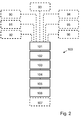
- Fig. 2 illustrates a method 100 according to some embodiments. All or some of the method steps indicated with dashed lines may be performed.
- the method 100 includes selecting 90 the predetermined environmental condition to represent at least one of a pre-determined temperature and a pre-determined temperature-range.
- a physical battery temperature is then replaced by a virtual value, which is indicative of a physical battery temperature. Since the alternator may charge the battery with different voltages depending on the battery temperature, the virtual value is used to control the alternator to charge the battery with a voltage which it normally would have charged a battery with at the specific temperature.
- the method 100 includes running 91 the internal combustion engine on idle speed for at least a pre-determined amount of time before providing the signal representative of a pre-determined environmental condition to the alternator.
- the pre-determined amount of time may be e.g. 30-120 seconds.
- the method 100 may include minimizing 92 of electrical loads and current consumers before providing the signal representative of a pre-determined environmental condition to the alternator. Further, is may be checked that there are no bad- or intermediate contacts between components, and that electrical connections are properly connected to each other. If any alternator fault codes are detected, they may be restored and/or fixed before the method 100 is performed.
- the method 100 may include controlling 93 the battery charge level to exceed a first predefined level.
- a higher charge level may render a more reliable test result, and according to some embodiments, the battery charge level shall exceed 50%. Otherwise the method 100 may be aborted and the battery charged before the method 100 is started again.
- the method 100 includes checking 94 if the battery current exceeds a predefined value. It may be valuable to gain information on the battery current level for various troubleshooting activities, before providing 102 a signal representative of a pre-determined environmental condition to the alternator or during other steps of the method 100.
- the method 100 may include checking 95 if the alternator load exceeds a predefined value. As mentioned above, this information may be used to check whether the battery is too discharged, if the alternator is substantially fully loaded, if electrical loads are correctly adjusted and/or if the different parts of the electrical system are properly connected to each other.
- the method 100 includes throttling 96 the internal combustion engine such that it exceeds a predetermined rpm for a predetermined amount of time, such that the alternator is allowed to self-magnetize.
- the method 100 is repeatedly performed for a plurality of different pre-determined environmental conditions.
- the control unit then outputs 107, an approved total test result only if an approved test result is achieved for each of the abovementioned plurality of different pre-determined environmental conditions.
- the functionality of the alternator may be controlled e.g. for a plurality of different temperatures, and the alternator may be overall approved only if the alternator is approved for all the tested temperatures. If the alternator fails for one or more temperatures, the alternator may need to be further tested and/or replaced.
- a test arrangement 1 for performing a diagnostic test of an alternator 2.
- the test arrangement 1, the alternator 2 and a battery 3 with a battery sensor 4 is comprised in a vehicle 5.
- the vehicle 5 further comprises an internal combustion engine 6 arranged to drive the alternator 2 and a control unit 7.
- the driven alternator 2 is arranged to charge the battery 3 via an electrical connection.
- the battery sensor 4 may be comprised in the battery 3 or may be connected to the battery 3.
- the battery sensor 4 is arranged to determine at least one of battery voltage, voltage of respective battery cells and current load.
- the sensor 4 is further arranged to provide the determined battery voltage and current load to the control unit 7.
- the control unit 7 is arranged to provide a signal representative of a pre-determined environmental condition to the alternator 2.
- the alternator 2 is, when driven by the idling internal combustion engine 6, arranged to provide an output voltage and output current to the battery 3 based on the predetermined environmental condition.
- the control unit 7 is arranged to compare the determined battery voltage with a predefined reference-voltage, representative of the pre-determined environmental condition, and to output an approved test result if the difference between the determined battery voltage and the pre-defined reference voltage falls within a predetermined range.
- the pre-defined reference-voltage may be an ideal voltage for a particular temperature, i.e. a voltage that the alternator normally would charge the battery with at a particular temperature, given that the alternator functions properly.
- the control unit 7 may be connected to an external test arrangement 8.
- the external test arrangement 8 may comprise one or more processing units and a user interface.
- a processing unit may be a central processing unit, CPU, also referred to as a central processor unit.
- CPU is hardware within a computer that carries out instructions of a computer program/software when this is executed by performing basic arithmetical, logical, and input/output operations.
- the test arrangement 8 may also comprise an accelerated processing unit, APU, also referred to as an advanced processing unit.
- An APU is a processing unit that includes additional processing capability designed to accelerate one or more types of computations outside of a CPU.
- the test arrangement 8 may also comprise an application programming interface, API, which specifies how software components may interact with each other.
- the test arrangement 8 may comprise one or more memory units in communication with the one or more processors.
- the test arrangement 8 may allow a user to input instructions to the control unit 7 via the user interface of the test arrangement 8. For example, a user may start and/or abort the method 100 via the test arrangement 8, and results from the method 100 may be communicated to the user via the test arrangement 8.
- the test arrangement 8 may be connected to remote servers, such that information may be transmitted between the vehicle and the remote servers.
- the test arrangement 8 may be arranged at a vehicle workshop, and may be connected via an OBD-connection arranged in the vehicle 5.
Abstract
Description
- Embodiments herein relate to a method for performing a diagnostic test of an alternator of a vehicle. Embodiments herein further relate to a test arrangement for performing a diagnostic test of an alternator of a vehicle and a vehicle comprising such a test arrangement.
- Vehicles equipped with an internal combustion engine normally comprise an alternator and a battery. When running, the internal combustion engine drives the alternator and the alternator is arranged to charge the battery. The battery may be used to provide electricity to a number of electrical consumers, such as spark plugs, headlights, climate control systems, entertainment systems and external chargers.
- In case of a failure in a component of the alternator-battery-chain, the electrical consumer may not receive enough electricity to function properly. For example, the alternator may fail to charge the battery, the battery may not be able to store the electricity in one or more cells of the battery for a sufficient amount of time, and/or a connection between the components may fail. In order to troubleshoot the cause of the failure, all or some of the different components normally must be tested, e.g. in a workshop.
-
US2006119365A1 describes a method and apparatus for testing a charge system of a vehicle. A test module is connected to a remote device, such as a battery tester, a scan tool, a personal computer or a personal digital assistant. The remote device is connected to a power source, which power source additionally provides power to the test module via the remote device. An alternator and/or a starter motor assembly is connected to the test module. The test module is capable of controlling a field current of the alternator and performing voltage and current measurements at prescribed test points in the vehicle starting and charging system. - In some situations test equipment, such as handheld workshop test equipment, incorrectly indicates that the alternator is broken, or fails to supply a sufficient amount of electricity to the battery. This could be caused e.g. by inaccuracy of voltage measurements, electrical loads in the vehicle electrical system which are affecting the test result and/or human factors, such as a workshop operator not following correct instructions.
- If test equipment incorrectly indicates an alternator failure, the alternator may be unnecessarily replaced in a workshop. This will lead to high costs for both customers and warranty providers.
- Clearly, there remains a need for eliminating or reducing the number of unnecessary alternator replacements.
- Embodiments herein aim to provide a method for performing a diagnostic test of an alternator of a vehicle, eliminating or at least reducing the problems and/or drawbacks described above.
- According to an embodiment, this is provided by a method for performing a diagnostic test of an alternator of a vehicle comprising an internal combustion engine arranged to drive the alternator and the driven alternator being arranged to charge a battery via an electrical connection thereto, wherein the method comprises; running the internal combustion engine at idle speed, providing, by a control unit, a signal representative of a pre-determined environmental condition to the alternator, providing, by the alternator, an output voltage and output current to the battery based on the pre-determined environmental condition, determining, by a sensor connected to the battery, at least one of the following; complete battery voltage, voltage of respective battery cells and current load, and providing the determined battery voltage and current load to the control unit, comparing, by the control unit, the determined battery voltage with a pre-defined reference-voltage representative of the pre-determined environmental condition and outputting, by the control unit, an approved test result if the difference between the determined battery voltage and the pre-defined reference voltage falls within a predetermined range.
- Since an approved test result is output if the difference between the determined battery voltage and the pre-defined reference voltage falls within a predetermined range, a capacity for the alternator in the selected pre-determined environmental condition is determined. A user, such as a mechanic at a workshop, who carries out the method for performing the diagnostic test of the alternator, is hereby informed of whether the alternator is functioning as expected in a selected pre-determined environmental condition.
- Since the control unit provides the input signal representative of a pre-determined environmental condition to the alternator, the method may be performed without any external handheld test equipment connected to the alternator. Thanks to the method, the vehicle alternator may be tested in a very reliable and economically efficient manner. In addition, a risk of errors relating to human factors, such as incorrect use of external handheld test equipment, which may lead to unnecessary replacement and/or repairing of the alternator or other vehicle parts is eliminated or at least reduced.
- Thus, hereby is provided a method for performing a diagnostic test of an alternator of a vehicle, eliminating or at least reducing the problems and/or drawbacks described above.
- According to some embodiments the abovementioned method-steps are performed for a plurality of different pre-determined environmental conditions. The method may further comprise; outputting, by the control unit, an approved total test result only if an approved test result is achieved for each of the plurality of different pre-determined environmental conditions.
- Since the steps are performed for a plurality of different pre-determined environmental conditions and an approved total test result is output only if an approved test result is achieved for each of the plurality of different pre-determined environmental conditions, the alternator is allowed to be tested in a simple, reliable and cost-efficient manner for a number of different pre-defined environmental conditions. Hereby the operability of the alternator may be tested and evaluated for an entire range of pre-defined environmental conditions, such that a total operability of the alternator over the range may be tested.
- According to some embodiments the method further comprises; selecting the predetermined environmental condition to represent at least one of a pre-determined temperature and a pre-determined temperature-range.
- Since the one or more pre-determined environmental condition may represent at least one of a pre-determined temperature and a pre-determined temperature-range, the alternator operability in different temperatures may be tested.
- A pre-determined environmental condition may be seen as a "virtual value", which replaces a temperature of the battery. The battery may be charged using different voltages for different temperatures. Charging may e.g. be improved if a cold battery is charged with a higher voltage than a warm battery.
- For example, the control unit may first provide the alternator with a signal representative of a pre-determined temperature of e.g. +60 degrees Celsius. The method-steps of determining, comparing and outputting a test result is performed. An approved test result for the pre-determined environmental condition of +60 degrees Celsius is output only if the difference between the determined battery voltage and the pre-defined reference voltage for +60 degrees Celsius is within a predetermined range. The pre-determined range may for example be less than one or two volts (V). According to some embodiments an approved test result is output only if the difference between the determined battery voltage and the pre-defined reference voltage is less than 0.5V. According to some embodiments the range is e.g. +/- 0.4V, +/-0.3V or +/-0.2V. A smaller range implies higher demands on the alternator.
- When the method steps has been performed for the pre-determined temperature of e.g. +60 degrees Celsius, the control unit provides a second signal representative of a second pre-determined temperature of e.g. +50 degrees Celsius to the alternator. The method-steps of determining, comparing and outputting a test result is performed. An approved test result for the pre-determined environmental condition of +50 degrees Celsius is output only if the difference between the determined battery voltage and the pre-defined reference voltage for +50 degrees Celsius is within a predetermined range.
- The control unit may continue to provide signals representative of a number of predetermined temperatures to the alternator. According to some embodiments, the signals are representative of +60, +50, +40, +30, +20, +10 and 0 degrees Celsius. These seven pre-determined temperatures may be suitable in some applications. In some embodiments fewer temperatures, such as four, five or six different temperatures are selected. In some embodiments a larger number, such as eight, nine or ten different temperatures are selected. Any temperatures, and number of different temperatures, may be selected, and may depend on vehicle model, market etc.
- When an approved test result has been output for all pre-determined temperatures, an approved total test result may be output. The alternator is then considered to function properly and does not need to be repaired or replaced.
- According to some embodiments the method comprises; running the internal combustion engine on idle speed for a pre-determined amount of time before providing the signal representative of a pre-determined environmental condition to the alternator. Since the internal combustion engine is kept idling a pre-determined amount of time before the signal is sent from the control unit to the alternator, any specific control unit/alternator settings which may be active a short time after start of the internal combustion engine may be ended. Hereby the method can be performed when the control unit/alternator is in a normal charge-mode.
- According to some embodiments the method comprises; minimizing electrical loads and current consumers before providing the signal representative of a pre-determined environmental condition to the alternator. Since electrical loads are set to a minimum, and any current consumers, such as defrosters, seat heating and external chargers are turned off, a more accurate test result may be achieved when the method is performed. In addition, a risk of a fully loaded and thereby saturated alternator is reduced. Hereby a probability that the alternator can keep a correct output voltage is highly increased. According to some embodiments the method comprises; controlling the battery charge level to exceed a first predefined level. Since the battery charge level is controlled to exceed a first predefined level, it may be ensured that the battery will accept charging current regardless of battery temperature. Generally, a cold battery has a lower charge acceptance than a warm battery. In addition, a more accurate test result may be achieved when the method is performed. The first predefined level may e.g. be set to at least 40-60% charge level.
- According to some embodiments the method comprises; checking if the battery current exceeds a predefined value, and according to some embodiments the method comprises; checking if the alternator load exceeds a predefined value.
- If the battery current exceeds a predefined value, for example 50 Ampere (A), and the alternator load exceeds a predefined value, such as 50 Watt (W), the battery may be considered to be too discharged for starting or continuing the method. Since it is checked if the battery current exceeds a predefined value, a user may charge the battery if necessary.
- If the battery current is less than a predefined value, for example 50 A, but higher than another predefined value, for example 0 A, and the alternator load is less than a predefined value, such as 50 W, the alternator may be loaded to a high extent. It may then be necessary to check if the electrical loads are correctly adjusted. It may also be necessary to let a cooling fan decrease a temperature of the engine. The method for performing a diagnostic test of the alternator may then be started or continued.
- If the battery current is less than a predefined level, for example 0 A and the alternator load exceeds a predefined value, such as 50 W, the method may need to be temporarily aborted. It may be necessary to check if the battery and the alternator are properly connected.
- If the battery current is less than a predefined level, such as near 0 A and the alternator load is less than a predefined value, such as 50 W, the alternator produces no electricity or an insufficient amount of electricity. Electricity may then be drawn from the battery. This may be caused by a defect alternator, or due to a defect connection between the alternator and a charge regulator.
- According to some embodiments the method comprises; throttling the combustion engine such that it exceeds a predetermined rpm for a predetermined amount of time. Since the internal combustion engine is throttled up it can produce more current and the alternator is allowed to self-magnetize. By increasing the number of revolutions per minute (rpm) during the testing, it may be excluded that a lack of output current from the alternator is a result of an insufficient rpm. An additional advantage is that if the alternator has not received a correct start-up-signal, the alternator will automatically start and produce current above a predetermined rpm. The alternator will thus enter a default back-up charging state. By throttling the engine, workshop mechanics can check whether the alternator is charging but the communication between different parts of the electrical system is defect, such as the communication between an alternator master node and an alternator regulator. This may be indicated if the alternator is charging the battery but not responds to the control signals from the alternator master node.
- Thus, hereby is provided a method for performing a diagnostic test of an alternator of a vehicle eliminating or at least reducing the problems and/or drawbacks described above.
- Embodiments herein also aim to provide a test arrangement for performing a diagnostic test of an alternator without the problems or drawbacks described above.
- According to an embodiment, this is provided by a test arrangement for performing a diagnostic test of an alternator of a vehicle comprising an internal combustion engine arranged to drive the alternator and the driven alternator being arranged to charge a battery via an electrical connection thereto, wherein the battery is connected to a battery sensor for determining at least one of battery voltage, voltage of respective battery cells and current load. A control unit is arranged to provide a signal representative of a predetermined environmental condition to the alternator. The alternator, when driven by the idling internal combustion engine, is arranged to provide an output voltage and output current to the battery based on the pre-determined environmental condition. The sensor is arranged to determine at least one of battery voltage, voltage of respective battery cells, current load and to provide the determined battery voltage and current load to the control unit. The control unit is arranged to compare the determined battery voltage with a pre-defined reference-voltage representative of the pre-determined environmental condition and to output an approved test result if the difference between the determined battery voltage and the pre-defined reference voltage falls within a predetermined range.
- Since the test arrangement is arranged to output an approved test result if the difference between the determined battery voltage and the pre-defined reference voltage falls within a predetermined range, a capacity for the alternator in the selected predetermined environmental condition is determined.
- Thus, hereby is provided a test arrangement for performing a diagnostic test of an alternator of a vehicle eliminating or at least reducing the problems and/or drawbacks described above.
- Embodiments herein also aim to provide a vehicle for performing a diagnostic test of an alternator without the problems or drawbacks described above.
- According to an embodiment, this is provided by a vehicle, wherein the vehicle comprises a test arrangement according embodiments herein.
- Since the vehicle comprises a test arrangement according embodiments herein, which vehicle test arrangement is arranged to output an approved test result if the difference between the determined battery voltage and the pre-defined reference voltage falls within a predetermined range, a capacity for the alternator in the selected predetermined environmental condition is determined.
- Thus, hereby is provided a vehicle eliminating or at least reducing the problems and/or drawbacks described above.
- Further features of, and advantages with, the embodiments herein will become apparent when studying the appended claims and the following detailed description.
- The various aspects of embodiments herein, including their particular features and advantages, will be readily understood from the following detailed description and the accompanying drawings, in which:
-
Fig. 1 illustrates a method for performing a diagnostic test of an alternator of a vehicle. -
Fig. 2 illustrates a method according to some embodiments. -
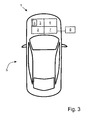
Fig. 3 illustrates a vehicle and a test arrangement. - Embodiments herein will now be described more fully with reference to the accompanying drawings, in which example embodiments are shown. Examples in the description wherein a particular voltage, current and/or amount of time is given are intended to be non-limiting, only used to illustrate some exemplifying embodiments. Disclosed features of example embodiments may be combined as readily understood by one of ordinary skill in the art to which this application belongs. Like numbers refer to like elements throughout.
- Well-known functions or constructions will not necessarily be described in detail for brevity and/or clarity.
-
Fig. 1 illustrates amethod 100 for performing a diagnostic test of an alternator of a vehicle. The vehicle comprises an internal combustion engine, which is arranged to drive the alternator. The vehicle may be e.g. a car, a recreational vehicle, a truck, a bus, an all-terrain-vehicle or a motorcycle. The method may be performed on substantially any vehicle comprising an internal combustion engine, a battery and an alternator. - An alternator in a vehicle is an electromechanical device that transfers mechanical energy from the internal combustion engine of the vehicle into electrical energy. The electrical energy may be provided in the form of an alternating current. The alternator may use a rotating magnetic field with a stationary armature, or a rotating armature with a stationary magnetic field. A charging output of the alternator, driven by an internal combustion engine at idle speed, may be used to charge a battery via an electrical connection between the alternator and the battery.
- The output current of the alternator may be e.g. 50-100 A at 12 V, depending on the loads in the vehicle electrical system. This may be sufficient for some vehicles, such as cars. If the vehicle is equipped with various electrical consumers, such as air conditioning, seat heaters and electrically powered steering assistance a higher voltage/current may be necessary. Commercial vehicles, often with combustion engines running on diesel, may need 24 V.
- In the
method 100 illustrated inFig. 1 the internal combustion engine is running 101 at idle speed. During idling the engine is disconnected from the vehicle drivetrain. Idle speed for internal combustion engines of cars are typically between 500-1000 rpm, but the idle speed may vary between different vehicle models. In commercial vehicles the idle speed is often between 500-600 rpm. - A control unit of the vehicle provides 102 a signal representative of a pre-determined environmental condition to the alternator. The signal representative of a pre-determined environmental condition, such as a selected temperature, may comprise e.g. charging voltage information. The control unit may comprise one or more processors with associated software and one or more memory units in communication with the one or more processors. The control unit may also comprise an application programming interface, API, which specifies how software components may interact with each other. The control unit may be arranged to control several vehicle functions and arrangements, and may be connectable to external test arrangements, e.g. via an on-board-diagnostic (OBD)-connection.
- The alternator provides 103, an output voltage and an output current to the battery based on the pre-determined environmental condition.
- The battery may comprise a sensor. Alternatively the battery is connected to a sensor.
- The sensor determines 104, at least one of the following; complete battery voltage, voltage of respective battery cells and current load. The sensor further provides the determined battery voltage and current load to the control unit.
- The control unit compares 105 the determined battery voltage with a pre-defined reference-voltage representative of the pre-determined environmental condition. The control unit further outputs 106, an approved test result if the difference between the determined battery voltage and the pre-defined reference voltage falls within a predetermined range. For example, the control unit only outputs an approved test result for a selected pre-determined condition if the difference between the determined battery voltage and the pre-defined reference voltage is within +/-0.2 or +/-0.3 V.
-
Fig. 2 illustrates amethod 100 according to some embodiments. All or some of the method steps indicated with dashed lines may be performed. - According to some embodiments, the
method 100 includes selecting 90 the predetermined environmental condition to represent at least one of a pre-determined temperature and a pre-determined temperature-range. A physical battery temperature is then replaced by a virtual value, which is indicative of a physical battery temperature. Since the alternator may charge the battery with different voltages depending on the battery temperature, the virtual value is used to control the alternator to charge the battery with a voltage which it normally would have charged a battery with at the specific temperature. - According to some embodiments, the
method 100 includes running 91 the internal combustion engine on idle speed for at least a pre-determined amount of time before providing the signal representative of a pre-determined environmental condition to the alternator. During idling electrical consumers may be minimized and the alternator may have time to return to a normal "charging mode" after the start of the internal combustion engine. The pre-determined amount of time may be e.g. 30-120 seconds. - In
Fig. 2 it is illustrated that themethod 100 may include minimizing 92 of electrical loads and current consumers before providing the signal representative of a pre-determined environmental condition to the alternator. Further, is may be checked that there are no bad- or intermediate contacts between components, and that electrical connections are properly connected to each other. If any alternator fault codes are detected, they may be restored and/or fixed before themethod 100 is performed. - The
method 100 may include controlling 93 the battery charge level to exceed a first predefined level. A higher charge level may render a more reliable test result, and according to some embodiments, the battery charge level shall exceed 50%. Otherwise themethod 100 may be aborted and the battery charged before themethod 100 is started again. - According to some embodiments, the
method 100 includes checking 94 if the battery current exceeds a predefined value. It may be valuable to gain information on the battery current level for various troubleshooting activities, before providing 102 a signal representative of a pre-determined environmental condition to the alternator or during other steps of themethod 100. - As illustrated in
Fig. 2 , themethod 100 may include checking 95 if the alternator load exceeds a predefined value. As mentioned above, this information may be used to check whether the battery is too discharged, if the alternator is substantially fully loaded, if electrical loads are correctly adjusted and/or if the different parts of the electrical system are properly connected to each other. - According to some embodiments, the
method 100 includes throttling 96 the internal combustion engine such that it exceeds a predetermined rpm for a predetermined amount of time, such that the alternator is allowed to self-magnetize. - According to some embodiments, the
method 100 is repeatedly performed for a plurality of different pre-determined environmental conditions. The control unit then outputs 107, an approved total test result only if an approved test result is achieved for each of the abovementioned plurality of different pre-determined environmental conditions. Hereby the functionality of the alternator may be controlled e.g. for a plurality of different temperatures, and the alternator may be overall approved only if the alternator is approved for all the tested temperatures. If the alternator fails for one or more temperatures, the alternator may need to be further tested and/or replaced. - In
Fig. 3 is illustrated atest arrangement 1 for performing a diagnostic test of analternator 2. Thetest arrangement 1, thealternator 2 and a battery 3 with a battery sensor 4 is comprised in avehicle 5. Thevehicle 5 further comprises aninternal combustion engine 6 arranged to drive thealternator 2 and acontrol unit 7. The drivenalternator 2 is arranged to charge the battery 3 via an electrical connection. - The battery sensor 4 may be comprised in the battery 3 or may be connected to the battery 3. The battery sensor 4 is arranged to determine at least one of battery voltage, voltage of respective battery cells and current load. The sensor 4 is further arranged to provide the determined battery voltage and current load to the control unit 7.The
control unit 7 is arranged to provide a signal representative of a pre-determined environmental condition to thealternator 2. - The
alternator 2 is, when driven by the idlinginternal combustion engine 6, arranged to provide an output voltage and output current to the battery 3 based on the predetermined environmental condition. - The
control unit 7 is arranged to compare the determined battery voltage with a predefined reference-voltage, representative of the pre-determined environmental condition, and to output an approved test result if the difference between the determined battery voltage and the pre-defined reference voltage falls within a predetermined range. The pre-defined reference-voltage may be an ideal voltage for a particular temperature, i.e. a voltage that the alternator normally would charge the battery with at a particular temperature, given that the alternator functions properly. - As illustrated in
Fig. 3 , thecontrol unit 7 may be connected to anexternal test arrangement 8. Theexternal test arrangement 8 may comprise one or more processing units and a user interface. A processing unit may be a central processing unit, CPU, also referred to as a central processor unit. A CPU is hardware within a computer that carries out instructions of a computer program/software when this is executed by performing basic arithmetical, logical, and input/output operations. Thetest arrangement 8 may also comprise an accelerated processing unit, APU, also referred to as an advanced processing unit. An APU is a processing unit that includes additional processing capability designed to accelerate one or more types of computations outside of a CPU. Thetest arrangement 8 may also comprise an application programming interface, API, which specifies how software components may interact with each other. - The
test arrangement 8 may comprise one or more memory units in communication with the one or more processors. Thetest arrangement 8 may allow a user to input instructions to thecontrol unit 7 via the user interface of thetest arrangement 8. For example, a user may start and/or abort themethod 100 via thetest arrangement 8, and results from themethod 100 may be communicated to the user via thetest arrangement 8. Thetest arrangement 8 may be connected to remote servers, such that information may be transmitted between the vehicle and the remote servers. Thetest arrangement 8 may be arranged at a vehicle workshop, and may be connected via an OBD-connection arranged in thevehicle 5. - As used herein, the term "comprising" or "comprises" is open-ended, and includes one or more stated features, elements, steps, components or functions but does not preclude the presence or addition of one or more other features, elements, steps, components, functions or groups thereof.
Claims (11)
- A method (100) for performing a diagnostic test of an alternator (2) of a vehicle (5) comprising an internal combustion engine (6) arranged to drive the alternator (2) and the driven alternator (2) being arranged to charge a battery (3) via an electrical connection thereto, characterized in that the method (100) comprises- running (101) the internal combustion engine (6) at idle speed,- providing (102), by a control unit (7), a signal representative of a predetermined environmental condition to the alternator (2),- providing (103), by the alternator (2), an output voltage and output current to the battery (3) based on the pre-determined environmental condition,- determining (104), by a sensor (4) connected to the battery (3), at least one of; complete battery voltage, voltage of respective battery cells and current load, and providing the determined battery voltage and current load to the control unit (7),- comparing (105), by the control unit (7), the determined battery voltage with a pre-defined reference-voltage representative of the pre-determined environmental condition and- outputting (106), by the control unit (7), an approved test result if the difference between the determined battery voltage and the pre-defined reference voltage falls within a predetermined range.
- The method (100) according to claim 1, characterized in that the steps in claim 1 are performed for a plurality of different pre-determined environmental conditions, and that the method (100) further comprises;- outputting (107), by the control unit (7), an approved total test result only if an approved test result is achieved for each of the plurality of different predetermined environmental conditions.
- The method (100) according to any one of claim 1 and claim 2, characterized in that the method (100) further comprises;- selecting (90) the pre-determined environmental condition to represent at least one of a pre-determined temperature and a pre-determined temperature-range.
- The method (100) according to any one of the previous claims, characterized in that the method (100) further comprises;- running (91) the internal combustion engine (6) on idle speed for a predetermined amount of time before providing the signal representative of a pre-determined environmental condition to the alternator (2).
- The method (100) according to any one of the previous claims, characterized in that the method (100) further comprises;- minimizing (92) electrical loads and current consumers before providing the signal representative of a pre-determined environmental condition to the alternator (2).
- The method (100) according to any one of the previous claims, characterized in that the method (100) further comprises;- controlling (93) the battery charge level to exceed a first predefined level.
- The method (100) according to any one of the previous claims, characterized in that the method (100) further comprises;- checking (94) if the battery current exceeds a predefined value.
- The method (100) according to any one of the previous claims, characterized in that the method (100) further comprises;- checking (95) if the alternator load exceeds a predefined value.
- The method (100) according to any one of the previous claims, characterized in that the method (100) further comprises;- throttling (96) the combustion engine (6) such that it exceeds a predetermined rpm for a predetermined amount of time.
- A test arrangement (1) for performing a diagnostic test of an alternator (2) of a vehicle (5) comprising an internal combustion engine (6) arranged to drive the alternator (2) and the driven alternator (2) being arranged to charge a battery (3) via an electrical connection thereto, characterized in that- the battery (3) is connected to a battery sensor (4) for determining at least one of battery voltage, voltage of respective battery cells, current load,- a control unit (7) is arranged to provide a signal representative of a predetermined environmental condition to the alternator (2),- the alternator (2), when driven by the idling internal combustion engine (6), is arranged to provide an output voltage and output current to the battery (3) based on the pre-determined environmental condition,- the sensor (4) is arranged to determine at least one of battery voltage, voltage of respective battery cells and current load and to provide the determined battery voltage and current load to the control unit (7),- the control unit (7) is arranged to compare the determined battery voltage with a pre-defined reference-voltage representative of the pre-determined environmental condition and to output an approved test result if the difference between the determined battery voltage and the pre-defined reference voltage falls within a predetermined range.
- A vehicle (5), characterized in that the vehicle (5) comprises a test arrangement (1) according to claim 10.
Priority Applications (3)
| Application Number | Priority Date | Filing Date | Title |
|---|---|---|---|
| EP14150768.1A EP2894485B1 (en) | 2014-01-10 | 2014-01-10 | Method for performing a diagnostic test of an alternator in a vehicle, test arrangement and vehicle |
| US14/578,547 US9864011B2 (en) | 2014-01-10 | 2014-12-22 | Method for performing a diagnostic test of an alternator in a vehicle, test arrangement and vehicle |
| CN201410828190.6A CN104777424B (en) | 2014-01-10 | 2014-12-26 | For executing the method, test arrangement and vehicle of the diagnostic test of the alternating current generator in vehicle |
Applications Claiming Priority (1)
| Application Number | Priority Date | Filing Date | Title |
|---|---|---|---|
| EP14150768.1A EP2894485B1 (en) | 2014-01-10 | 2014-01-10 | Method for performing a diagnostic test of an alternator in a vehicle, test arrangement and vehicle |
Publications (2)
| Publication Number | Publication Date |
|---|---|
| EP2894485A1 true EP2894485A1 (en) | 2015-07-15 |
| EP2894485B1 EP2894485B1 (en) | 2019-10-16 |
Family
ID=49943199
Family Applications (1)
| Application Number | Title | Priority Date | Filing Date |
|---|---|---|---|
| EP14150768.1A Active EP2894485B1 (en) | 2014-01-10 | 2014-01-10 | Method for performing a diagnostic test of an alternator in a vehicle, test arrangement and vehicle |
Country Status (3)
| Country | Link |
|---|---|
| US (1) | US9864011B2 (en) |
| EP (1) | EP2894485B1 (en) |
| CN (1) | CN104777424B (en) |
Families Citing this family (4)
| Publication number | Priority date | Publication date | Assignee | Title |
|---|---|---|---|---|
| DE102013224344A1 (en) * | 2013-11-28 | 2015-05-28 | Robert Bosch Gmbh | Device and method for testing a vehicle battery |
| US9589394B2 (en) * | 2015-07-16 | 2017-03-07 | GM Global Technology Operations LLC | Determining the source of a ground offset in a controller area network |
| CN107356871B (en) * | 2017-06-30 | 2019-12-13 | 北京交通大学 | motor monitoring method and device |
| CN111624500B (en) * | 2020-07-10 | 2023-06-27 | 深圳市道通科技股份有限公司 | Method for detecting vehicle generator and battery detector |
Citations (5)
| Publication number | Priority date | Publication date | Assignee | Title |
|---|---|---|---|---|
| EP0591871A1 (en) * | 1992-10-05 | 1994-04-13 | IVECO FIAT S.p.A. | A method and apparatus for the diagnostic testing of electrical equipment of a vehicle |
| US6466025B1 (en) * | 2000-01-13 | 2002-10-15 | Midtronics, Inc. | Alternator tester |
| US20050035752A1 (en) * | 1996-07-29 | 2005-02-17 | Bertness Kevin I. | Alternator tester |
| US20060119365A1 (en) | 2004-12-07 | 2006-06-08 | Surender Makhija | Testing apparatus and method for vehicle starting and charging system |
| US20060244456A1 (en) * | 2005-04-28 | 2006-11-02 | Auto Meter Products, Inc. | Heavy duty charging and starting system testor and method |
Family Cites Families (12)
| Publication number | Priority date | Publication date | Assignee | Title |
|---|---|---|---|---|
| US5151647A (en) * | 1991-05-15 | 1992-09-29 | Chrysler Corporation | Enhanced charging system diagnostic method |
| JP3102981B2 (en) * | 1993-12-28 | 2000-10-23 | 三菱電機株式会社 | Output control device for vehicle alternator |
| US6150793A (en) * | 1996-02-29 | 2000-11-21 | Vehicle Enhancement Systems, Inc. | System and method for managing the electrical system of a vehicle |
| US6242921B1 (en) * | 1998-10-30 | 2001-06-05 | Snap-On Tools Company | Alternator testing apparatus and method |
| US6194877B1 (en) * | 1999-08-02 | 2001-02-27 | Visteon Global Technologies, Inc. | Fault detection in a motor vehicle charging system |
| KR20030069802A (en) * | 2000-06-26 | 2003-08-27 | 스넵-온 테크놀로지스 인코포레이티드 | Alternator testing method and system using ripple detection |
| US6862504B2 (en) * | 2002-09-10 | 2005-03-01 | Bendix Commercial Vehicle Systems Llc | System and method for detecting alternator condition |
| FR2876514B1 (en) * | 2004-10-08 | 2007-04-13 | Peugeot Citroen Automobiles Sa | DEVICE FOR CONTROLLING A MOTOR VEHICLE ALTERNATOR IN ACCORDANCE WITH THE LIFE SITUATION OF THIS VEHICLE, AND ASSOCIATED METHOD |
| US7990155B2 (en) * | 2005-04-28 | 2011-08-02 | Auto Meter Products, Inc. | Heavy duty battery system tester and method |
| DE112008001881B4 (en) * | 2007-07-17 | 2024-04-11 | Midtronics, Inc. | Battery tester for electric vehicles |
| JP4518156B2 (en) * | 2008-01-28 | 2010-08-04 | 株式会社デンソー | Vehicle system |
| EP2453546A1 (en) * | 2010-11-12 | 2012-05-16 | Fiat Powertrain Technologies S.p.A. | Automotive electrical system previded with an alternator electronic control system |
-
2014
- 2014-01-10 EP EP14150768.1A patent/EP2894485B1/en active Active
- 2014-12-22 US US14/578,547 patent/US9864011B2/en active Active
- 2014-12-26 CN CN201410828190.6A patent/CN104777424B/en active Active
Patent Citations (5)
| Publication number | Priority date | Publication date | Assignee | Title |
|---|---|---|---|---|
| EP0591871A1 (en) * | 1992-10-05 | 1994-04-13 | IVECO FIAT S.p.A. | A method and apparatus for the diagnostic testing of electrical equipment of a vehicle |
| US20050035752A1 (en) * | 1996-07-29 | 2005-02-17 | Bertness Kevin I. | Alternator tester |
| US6466025B1 (en) * | 2000-01-13 | 2002-10-15 | Midtronics, Inc. | Alternator tester |
| US20060119365A1 (en) | 2004-12-07 | 2006-06-08 | Surender Makhija | Testing apparatus and method for vehicle starting and charging system |
| US20060244456A1 (en) * | 2005-04-28 | 2006-11-02 | Auto Meter Products, Inc. | Heavy duty charging and starting system testor and method |
Also Published As
| Publication number | Publication date |
|---|---|
| US9864011B2 (en) | 2018-01-09 |
| EP2894485B1 (en) | 2019-10-16 |
| US20150198669A1 (en) | 2015-07-16 |
| CN104777424B (en) | 2019-09-20 |
| CN104777424A (en) | 2015-07-15 |
Similar Documents
| Publication | Publication Date | Title |
|---|---|---|
| US6466025B1 (en) | Alternator tester | |
| US20180029474A1 (en) | Redundant power supply | |
| US8818611B2 (en) | Method and apparatus to evaluate a starting system for an internal combustion engine | |
| US9864011B2 (en) | Method for performing a diagnostic test of an alternator in a vehicle, test arrangement and vehicle | |
| US10031188B2 (en) | System for estimating state of health of battery of electric vehicle | |
| US8311725B2 (en) | Eco-run control device and eco-run control method | |
| US20080071440A1 (en) | Method and System of Power Management for a Vehicle Communication Interface | |
| US20170115370A1 (en) | Apparatus and method of diagnosing current sensor of eco-friendly vehicle | |
| CN109839549B (en) | Real-time monitoring method and device for working state of vehicle starting system | |
| WO2009151737A1 (en) | System and method for monitoring the state of charge of a battery | |
| US20170136914A1 (en) | Systems and methods for visualizing battery data | |
| Zhang et al. | Fault diagnosis of automotive electric power generation and storage systems | |
| CN104620468B (en) | Method for determining the carrying capacity in Vehicular battery | |
| US20190242325A1 (en) | Fault diagnosis of electronic control unit (ecu) | |
| CN104303037A (en) | External diagnosis device, motorcycle diagnosis system and vehicle diagnosis method | |
| CN103376407A (en) | Method and arrangement for diagnosing drivers of contactors, battery, and motor vehicle having such a battery | |
| JP2016184995A (en) | Electric vehicle | |
| US20220236334A1 (en) | Apparatus and method for diagnosing a battery fault | |
| US11585307B2 (en) | System and method for controlling vehicle stop-start function based on measured and predicted cranking voltages and adaptive adjustment of circuit resistance | |
| CN114729970A (en) | Battery diagnostics for electrically operated vehicles | |
| CN110344984A (en) | The method of the state for the vehicle-mounted voltage network that electronic measuring device, starter and the determination of the starter of internal combustion engine are connect with starter | |
| CN114355214B (en) | Battery diagnosis device, method, storage medium, and vehicle | |
| KR102420369B1 (en) | Apparatus of testing dual power system for automobile | |
| Mani et al. | Experimental analysis of faults of automobile starting | |
| JP7380535B2 (en) | Battery monitoring device, method, program, and vehicle |
Legal Events
| Date | Code | Title | Description |
|---|---|---|---|
| PUAI | Public reference made under article 153(3) epc to a published international application that has entered the european phase |
Free format text: ORIGINAL CODE: 0009012 |
|
| 17P | Request for examination filed |
Effective date: 20140110 |
|
| AK | Designated contracting states |
Kind code of ref document: A1 Designated state(s): AL AT BE BG CH CY CZ DE DK EE ES FI FR GB GR HR HU IE IS IT LI LT LU LV MC MK MT NL NO PL PT RO RS SE SI SK SM TR |
|
| AX | Request for extension of the european patent |
Extension state: BA ME |
|
| R17P | Request for examination filed (corrected) |
Effective date: 20160115 |
|
| RBV | Designated contracting states (corrected) |
Designated state(s): AL AT BE BG CH CY CZ DE DK EE ES FI FR GB GR HR HU IE IS IT LI LT LU LV MC MK MT NL NO PL PT RO RS SE SI SK SM TR |
|
| RIC1 | Information provided on ipc code assigned before grant |
Ipc: G01R 31/34 20060101AFI20190404BHEP |
|
| GRAJ | Information related to disapproval of communication of intention to grant by the applicant or resumption of examination proceedings by the epo deleted |
Free format text: ORIGINAL CODE: EPIDOSDIGR1 |
|
| GRAP | Despatch of communication of intention to grant a patent |
Free format text: ORIGINAL CODE: EPIDOSNIGR1 |
|
| STAA | Information on the status of an ep patent application or granted ep patent |
Free format text: STATUS: REQUEST FOR EXAMINATION WAS MADE |
|
| GRAP | Despatch of communication of intention to grant a patent |
Free format text: ORIGINAL CODE: EPIDOSNIGR1 |
|
| STAA | Information on the status of an ep patent application or granted ep patent |
Free format text: STATUS: GRANT OF PATENT IS INTENDED |
|
| INTG | Intention to grant announced |
Effective date: 20190522 |
|
| RAP1 | Party data changed (applicant data changed or rights of an application transferred) |
Owner name: VOLVO CAR CORPORATION |
|
| GRAS | Grant fee paid |
Free format text: ORIGINAL CODE: EPIDOSNIGR3 |
|
| GRAA | (expected) grant |
Free format text: ORIGINAL CODE: 0009210 |
|
| STAA | Information on the status of an ep patent application or granted ep patent |
Free format text: STATUS: THE PATENT HAS BEEN GRANTED |
|
| AK | Designated contracting states |
Kind code of ref document: B1 Designated state(s): AL AT BE BG CH CY CZ DE DK EE ES FI FR GB GR HR HU IE IS IT LI LT LU LV MC MK MT NL NO PL PT RO RS SE SI SK SM TR |
|
| REG | Reference to a national code |
Ref country code: GB Ref legal event code: FG4D |
|
| REG | Reference to a national code |
Ref country code: CH Ref legal event code: EP |
|
| REG | Reference to a national code |
Ref country code: DE Ref legal event code: R096 Ref document number: 602014055127 Country of ref document: DE |
|
| REG | Reference to a national code |
Ref country code: IE Ref legal event code: FG4D |
|
| REG | Reference to a national code |
Ref country code: AT Ref legal event code: REF Ref document number: 1191797 Country of ref document: AT Kind code of ref document: T Effective date: 20191115 |
|
| REG | Reference to a national code |
Ref country code: NL Ref legal event code: MP Effective date: 20191016 |
|
| REG | Reference to a national code |
Ref country code: LT Ref legal event code: MG4D |
|
| REG | Reference to a national code |
Ref country code: AT Ref legal event code: MK05 Ref document number: 1191797 Country of ref document: AT Kind code of ref document: T Effective date: 20191016 |
|
| PG25 | Lapsed in a contracting state [announced via postgrant information from national office to epo] |
Ref country code: NL Free format text: LAPSE BECAUSE OF FAILURE TO SUBMIT A TRANSLATION OF THE DESCRIPTION OR TO PAY THE FEE WITHIN THE PRESCRIBED TIME-LIMIT Effective date: 20191016 Ref country code: AT Free format text: LAPSE BECAUSE OF FAILURE TO SUBMIT A TRANSLATION OF THE DESCRIPTION OR TO PAY THE FEE WITHIN THE PRESCRIBED TIME-LIMIT Effective date: 20191016 Ref country code: PL Free format text: LAPSE BECAUSE OF FAILURE TO SUBMIT A TRANSLATION OF THE DESCRIPTION OR TO PAY THE FEE WITHIN THE PRESCRIBED TIME-LIMIT Effective date: 20191016 Ref country code: LV Free format text: LAPSE BECAUSE OF FAILURE TO SUBMIT A TRANSLATION OF THE DESCRIPTION OR TO PAY THE FEE WITHIN THE PRESCRIBED TIME-LIMIT Effective date: 20191016 Ref country code: SE Free format text: LAPSE BECAUSE OF FAILURE TO SUBMIT A TRANSLATION OF THE DESCRIPTION OR TO PAY THE FEE WITHIN THE PRESCRIBED TIME-LIMIT Effective date: 20191016 Ref country code: NO Free format text: LAPSE BECAUSE OF FAILURE TO SUBMIT A TRANSLATION OF THE DESCRIPTION OR TO PAY THE FEE WITHIN THE PRESCRIBED TIME-LIMIT Effective date: 20200116 Ref country code: FI Free format text: LAPSE BECAUSE OF FAILURE TO SUBMIT A TRANSLATION OF THE DESCRIPTION OR TO PAY THE FEE WITHIN THE PRESCRIBED TIME-LIMIT Effective date: 20191016 Ref country code: BG Free format text: LAPSE BECAUSE OF FAILURE TO SUBMIT A TRANSLATION OF THE DESCRIPTION OR TO PAY THE FEE WITHIN THE PRESCRIBED TIME-LIMIT Effective date: 20200116 Ref country code: PT Free format text: LAPSE BECAUSE OF FAILURE TO SUBMIT A TRANSLATION OF THE DESCRIPTION OR TO PAY THE FEE WITHIN THE PRESCRIBED TIME-LIMIT Effective date: 20200217 Ref country code: ES Free format text: LAPSE BECAUSE OF FAILURE TO SUBMIT A TRANSLATION OF THE DESCRIPTION OR TO PAY THE FEE WITHIN THE PRESCRIBED TIME-LIMIT Effective date: 20191016 Ref country code: GR Free format text: LAPSE BECAUSE OF FAILURE TO SUBMIT A TRANSLATION OF THE DESCRIPTION OR TO PAY THE FEE WITHIN THE PRESCRIBED TIME-LIMIT Effective date: 20200117 Ref country code: LT Free format text: LAPSE BECAUSE OF FAILURE TO SUBMIT A TRANSLATION OF THE DESCRIPTION OR TO PAY THE FEE WITHIN THE PRESCRIBED TIME-LIMIT Effective date: 20191016 |
|
| PG25 | Lapsed in a contracting state [announced via postgrant information from national office to epo] |
Ref country code: HR Free format text: LAPSE BECAUSE OF FAILURE TO SUBMIT A TRANSLATION OF THE DESCRIPTION OR TO PAY THE FEE WITHIN THE PRESCRIBED TIME-LIMIT Effective date: 20191016 Ref country code: RS Free format text: LAPSE BECAUSE OF FAILURE TO SUBMIT A TRANSLATION OF THE DESCRIPTION OR TO PAY THE FEE WITHIN THE PRESCRIBED TIME-LIMIT Effective date: 20191016 Ref country code: IS Free format text: LAPSE BECAUSE OF FAILURE TO SUBMIT A TRANSLATION OF THE DESCRIPTION OR TO PAY THE FEE WITHIN THE PRESCRIBED TIME-LIMIT Effective date: 20200224 |
|
| PG25 | Lapsed in a contracting state [announced via postgrant information from national office to epo] |
Ref country code: AL Free format text: LAPSE BECAUSE OF FAILURE TO SUBMIT A TRANSLATION OF THE DESCRIPTION OR TO PAY THE FEE WITHIN THE PRESCRIBED TIME-LIMIT Effective date: 20191016 |
|
| REG | Reference to a national code |
Ref country code: DE Ref legal event code: R097 Ref document number: 602014055127 Country of ref document: DE |
|
| PG2D | Information on lapse in contracting state deleted |
Ref country code: IS |
|
| PG25 | Lapsed in a contracting state [announced via postgrant information from national office to epo] |
Ref country code: RO Free format text: LAPSE BECAUSE OF FAILURE TO SUBMIT A TRANSLATION OF THE DESCRIPTION OR TO PAY THE FEE WITHIN THE PRESCRIBED TIME-LIMIT Effective date: 20191016 Ref country code: CZ Free format text: LAPSE BECAUSE OF FAILURE TO SUBMIT A TRANSLATION OF THE DESCRIPTION OR TO PAY THE FEE WITHIN THE PRESCRIBED TIME-LIMIT Effective date: 20191016 Ref country code: EE Free format text: LAPSE BECAUSE OF FAILURE TO SUBMIT A TRANSLATION OF THE DESCRIPTION OR TO PAY THE FEE WITHIN THE PRESCRIBED TIME-LIMIT Effective date: 20191016 Ref country code: DK Free format text: LAPSE BECAUSE OF FAILURE TO SUBMIT A TRANSLATION OF THE DESCRIPTION OR TO PAY THE FEE WITHIN THE PRESCRIBED TIME-LIMIT Effective date: 20191016 Ref country code: IS Free format text: LAPSE BECAUSE OF FAILURE TO SUBMIT A TRANSLATION OF THE DESCRIPTION OR TO PAY THE FEE WITHIN THE PRESCRIBED TIME-LIMIT Effective date: 20200216 |
|
| PLBE | No opposition filed within time limit |
Free format text: ORIGINAL CODE: 0009261 |
|
| STAA | Information on the status of an ep patent application or granted ep patent |
Free format text: STATUS: NO OPPOSITION FILED WITHIN TIME LIMIT |
|
| PG25 | Lapsed in a contracting state [announced via postgrant information from national office to epo] |
Ref country code: SM Free format text: LAPSE BECAUSE OF FAILURE TO SUBMIT A TRANSLATION OF THE DESCRIPTION OR TO PAY THE FEE WITHIN THE PRESCRIBED TIME-LIMIT Effective date: 20191016 Ref country code: SK Free format text: LAPSE BECAUSE OF FAILURE TO SUBMIT A TRANSLATION OF THE DESCRIPTION OR TO PAY THE FEE WITHIN THE PRESCRIBED TIME-LIMIT Effective date: 20191016 Ref country code: MC Free format text: LAPSE BECAUSE OF FAILURE TO SUBMIT A TRANSLATION OF THE DESCRIPTION OR TO PAY THE FEE WITHIN THE PRESCRIBED TIME-LIMIT Effective date: 20191016 |
|
| REG | Reference to a national code |
Ref country code: CH Ref legal event code: PL |
|
| 26N | No opposition filed |
Effective date: 20200717 |
|
| GBPC | Gb: european patent ceased through non-payment of renewal fee |
Effective date: 20200116 |
|
| REG | Reference to a national code |
Ref country code: BE Ref legal event code: MM Effective date: 20200131 |
|
| PG25 | Lapsed in a contracting state [announced via postgrant information from national office to epo] |
Ref country code: LU Free format text: LAPSE BECAUSE OF NON-PAYMENT OF DUE FEES Effective date: 20200110 Ref country code: GB Free format text: LAPSE BECAUSE OF NON-PAYMENT OF DUE FEES Effective date: 20200116 |
|
| PG25 | Lapsed in a contracting state [announced via postgrant information from national office to epo] |
Ref country code: CH Free format text: LAPSE BECAUSE OF NON-PAYMENT OF DUE FEES Effective date: 20200131 Ref country code: BE Free format text: LAPSE BECAUSE OF NON-PAYMENT OF DUE FEES Effective date: 20200131 Ref country code: SI Free format text: LAPSE BECAUSE OF FAILURE TO SUBMIT A TRANSLATION OF THE DESCRIPTION OR TO PAY THE FEE WITHIN THE PRESCRIBED TIME-LIMIT Effective date: 20191016 Ref country code: LI Free format text: LAPSE BECAUSE OF NON-PAYMENT OF DUE FEES Effective date: 20200131 |
|
| PG25 | Lapsed in a contracting state [announced via postgrant information from national office to epo] |
Ref country code: IE Free format text: LAPSE BECAUSE OF NON-PAYMENT OF DUE FEES Effective date: 20200110 |
|
| PG25 | Lapsed in a contracting state [announced via postgrant information from national office to epo] |
Ref country code: TR Free format text: LAPSE BECAUSE OF FAILURE TO SUBMIT A TRANSLATION OF THE DESCRIPTION OR TO PAY THE FEE WITHIN THE PRESCRIBED TIME-LIMIT Effective date: 20191016 Ref country code: MT Free format text: LAPSE BECAUSE OF FAILURE TO SUBMIT A TRANSLATION OF THE DESCRIPTION OR TO PAY THE FEE WITHIN THE PRESCRIBED TIME-LIMIT Effective date: 20191016 Ref country code: CY Free format text: LAPSE BECAUSE OF FAILURE TO SUBMIT A TRANSLATION OF THE DESCRIPTION OR TO PAY THE FEE WITHIN THE PRESCRIBED TIME-LIMIT Effective date: 20191016 |
|
| PG25 | Lapsed in a contracting state [announced via postgrant information from national office to epo] |
Ref country code: MK Free format text: LAPSE BECAUSE OF FAILURE TO SUBMIT A TRANSLATION OF THE DESCRIPTION OR TO PAY THE FEE WITHIN THE PRESCRIBED TIME-LIMIT Effective date: 20191016 |
|
| PGFP | Annual fee paid to national office [announced via postgrant information from national office to epo] |
Ref country code: IT Payment date: 20230103 Year of fee payment: 10 Ref country code: DE Payment date: 20221220 Year of fee payment: 10 |
|
| P01 | Opt-out of the competence of the unified patent court (upc) registered |
Effective date: 20231212 |
|
| PGFP | Annual fee paid to national office [announced via postgrant information from national office to epo] |
Ref country code: FR Payment date: 20231219 Year of fee payment: 11 |