EP2913690A1 - Positioning system and method - Google Patents
Positioning system and method Download PDFInfo
- Publication number
- EP2913690A1 EP2913690A1 EP14174729.5A EP14174729A EP2913690A1 EP 2913690 A1 EP2913690 A1 EP 2913690A1 EP 14174729 A EP14174729 A EP 14174729A EP 2913690 A1 EP2913690 A1 EP 2913690A1
- Authority
- EP
- European Patent Office
- Prior art keywords
- signal
- receiver
- gps
- transmitter
- reception
- Prior art date
- Legal status (The legal status is an assumption and is not a legal conclusion. Google has not performed a legal analysis and makes no representation as to the accuracy of the status listed.)
- Granted
Links
Images

Classifications
-
- G—PHYSICS
- G01—MEASURING; TESTING
- G01S—RADIO DIRECTION-FINDING; RADIO NAVIGATION; DETERMINING DISTANCE OR VELOCITY BY USE OF RADIO WAVES; LOCATING OR PRESENCE-DETECTING BY USE OF THE REFLECTION OR RERADIATION OF RADIO WAVES; ANALOGOUS ARRANGEMENTS USING OTHER WAVES
- G01S13/00—Systems using the reflection or reradiation of radio waves, e.g. radar systems; Analogous systems using reflection or reradiation of waves whose nature or wavelength is irrelevant or unspecified
- G01S13/02—Systems using reflection of radio waves, e.g. primary radar systems; Analogous systems
- G01S13/50—Systems of measurement based on relative movement of target
- G01S13/58—Velocity or trajectory determination systems; Sense-of-movement determination systems
- G01S13/581—Velocity or trajectory determination systems; Sense-of-movement determination systems using transmission of interrupted pulse modulated waves and based upon the Doppler effect resulting from movement of targets
- G01S13/582—Velocity or trajectory determination systems; Sense-of-movement determination systems using transmission of interrupted pulse modulated waves and based upon the Doppler effect resulting from movement of targets adapted for simultaneous range and velocity measurements
-
- G—PHYSICS
- G01—MEASURING; TESTING
- G01S—RADIO DIRECTION-FINDING; RADIO NAVIGATION; DETERMINING DISTANCE OR VELOCITY BY USE OF RADIO WAVES; LOCATING OR PRESENCE-DETECTING BY USE OF THE REFLECTION OR RERADIATION OF RADIO WAVES; ANALOGOUS ARRANGEMENTS USING OTHER WAVES
- G01S13/00—Systems using the reflection or reradiation of radio waves, e.g. radar systems; Analogous systems using reflection or reradiation of waves whose nature or wavelength is irrelevant or unspecified
- G01S13/003—Bistatic radar systems; Multistatic radar systems
-
- G—PHYSICS
- G01—MEASURING; TESTING
- G01S—RADIO DIRECTION-FINDING; RADIO NAVIGATION; DETERMINING DISTANCE OR VELOCITY BY USE OF RADIO WAVES; LOCATING OR PRESENCE-DETECTING BY USE OF THE REFLECTION OR RERADIATION OF RADIO WAVES; ANALOGOUS ARRANGEMENTS USING OTHER WAVES
- G01S13/00—Systems using the reflection or reradiation of radio waves, e.g. radar systems; Analogous systems using reflection or reradiation of waves whose nature or wavelength is irrelevant or unspecified
- G01S13/02—Systems using reflection of radio waves, e.g. primary radar systems; Analogous systems
- G01S13/06—Systems determining position data of a target
- G01S13/08—Systems for measuring distance only
- G01S13/10—Systems for measuring distance only using transmission of interrupted, pulse modulated waves
- G01S13/18—Systems for measuring distance only using transmission of interrupted, pulse modulated waves wherein range gates are used
-
- G—PHYSICS
- G01—MEASURING; TESTING
- G01S—RADIO DIRECTION-FINDING; RADIO NAVIGATION; DETERMINING DISTANCE OR VELOCITY BY USE OF RADIO WAVES; LOCATING OR PRESENCE-DETECTING BY USE OF THE REFLECTION OR RERADIATION OF RADIO WAVES; ANALOGOUS ARRANGEMENTS USING OTHER WAVES
- G01S13/00—Systems using the reflection or reradiation of radio waves, e.g. radar systems; Analogous systems using reflection or reradiation of waves whose nature or wavelength is irrelevant or unspecified
- G01S13/66—Radar-tracking systems; Analogous systems
- G01S13/70—Radar-tracking systems; Analogous systems for range tracking only
-
- G—PHYSICS
- G01—MEASURING; TESTING
- G01S—RADIO DIRECTION-FINDING; RADIO NAVIGATION; DETERMINING DISTANCE OR VELOCITY BY USE OF RADIO WAVES; LOCATING OR PRESENCE-DETECTING BY USE OF THE REFLECTION OR RERADIATION OF RADIO WAVES; ANALOGOUS ARRANGEMENTS USING OTHER WAVES
- G01S13/00—Systems using the reflection or reradiation of radio waves, e.g. radar systems; Analogous systems using reflection or reradiation of waves whose nature or wavelength is irrelevant or unspecified
- G01S13/86—Combinations of radar systems with non-radar systems, e.g. sonar, direction finder
-
- G—PHYSICS
- G01—MEASURING; TESTING
- G01S—RADIO DIRECTION-FINDING; RADIO NAVIGATION; DETERMINING DISTANCE OR VELOCITY BY USE OF RADIO WAVES; LOCATING OR PRESENCE-DETECTING BY USE OF THE REFLECTION OR RERADIATION OF RADIO WAVES; ANALOGOUS ARRANGEMENTS USING OTHER WAVES
- G01S7/00—Details of systems according to groups G01S13/00, G01S15/00, G01S17/00
- G01S7/02—Details of systems according to groups G01S13/00, G01S15/00, G01S17/00 of systems according to group G01S13/00
- G01S7/28—Details of pulse systems
-
- G—PHYSICS
- G01—MEASURING; TESTING
- G01S—RADIO DIRECTION-FINDING; RADIO NAVIGATION; DETERMINING DISTANCE OR VELOCITY BY USE OF RADIO WAVES; LOCATING OR PRESENCE-DETECTING BY USE OF THE REFLECTION OR RERADIATION OF RADIO WAVES; ANALOGOUS ARRANGEMENTS USING OTHER WAVES
- G01S7/00—Details of systems according to groups G01S13/00, G01S15/00, G01S17/00
- G01S7/02—Details of systems according to groups G01S13/00, G01S15/00, G01S17/00 of systems according to group G01S13/00
- G01S7/40—Means for monitoring or calibrating
Definitions
- Embodiments described herein relate generally to a positioning system and method for estimating the position of a target such as an aircraft.
- a Multi-Static Primary Surveillance Radar includes a transmitter and a plurality of receivers.
- the transmitter radiates a pulsed radio wave.
- Each receiver receives a reflected wave (echo signal) returned from a target.
- the position (range) of the target can be estimated by performing elliptical positioning for each receiver based on the time difference between transmission and reception.
- the target can be specified by hyperbolic positioning between a plurality of transmission/reception channels using the combinations of the transmitter and the receivers.
- the receiver cannot correctly receive the reflected wave because of the reception environment, reception sensitivity, or the like. This leads to deterioration of the observation accuracy and tracking performance and errors in position estimation. It is demanded to cope with these problems.
- a positioning system includes a transmitter apparatus and a receiver apparatus.
- the transmitter apparatus transmits a radio wave.
- the receiver apparatus receives a reflected wave from a target.
- the transmitter apparatus comprises a first GPS receiver and a transmitter.
- the first GPS receiver receives a GPS (Global Positioning System) signal and outputs a reference signal.
- the transmitter transmits the radio wave at a predetermined time interval based on the reference signal.
- the receiver apparatus includes a second GPS receiver, a detector, a Doppler frequency calculator, and an arrival time difference calculator.
- the second GPS receiver receives the GPS signal and outputs time information.
- the detector receives the reflected wave and outputs a reception signal to which the received time information is added.
- the Doppler frequency calculator calculates a Doppler frequency based on a reception frequency of the reception signal and a transmission frequency of the radio wave.
- the arrival time difference calculator calculates an arrival time difference of the reflected wave based on the Doppler frequency.
- the detector sets a time filter to receive a next pulse based on the arrival time difference and the time information added to the reception signal.
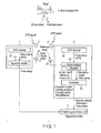
- FIG. 1 is a view showing an example of a positioning system according to an embodiment.
- This positioning system includes a transmitter apparatus 1, a receiver apparatus 2, and a positioning processor unit 3.
- the transmitter apparatus 1 and the receiver apparatus 2 are communicably connected to the positioning processor unit 3 via a network.
- the transmitter apparatus 1 transmits a pulsed radio wave to a target.
- the receiver apparatus 2 receives a reflected wave from the target.
- the positioning processor unit 3 estimates the position of the target.
- a system including the transmitter apparatus 1 and the receiver apparatus 2 is a so-called bi-static system.
- a system having a plurality of combinations of the transmitter apparatus 1 and the receiver apparatuses 2 is a so-called multi-static system.
- a bi-static system will be described here for the sake of simplicity.
- the transmitter apparatus 1 includes a GPS (Global Positioning System) antenna 11, a GPS receiver 12, a signal transmitter 13, and a transmission antenna 14.
- the GPS receiver 12 receives a GPS signal from a GPS satellite by the GPS antenna 11, and outputs a time stamp and a 1PPS (Pulse Per Second) signal to the signal transmitter 13.
- the time stamp corresponds to the time at which the GPS signal is received.
- the signal transmitter 13 radiates radio waves from the transmission antenna 14 at a predetermined time interval.
- the radio wave transmission timing is controlled based on the 1PPS signal output from the GPS receiver 12.
- the signal transmitter 13 notifies the positioning processor unit 3 of the radio wave transmission time using the time stamp.
- the 1PPS signal is a reference signal transmitted from the GPS satellite once a second, and is used as the radio wave transmission time synchronization signal of the signal transmitter 13.
- the accuracy of the 1PPS signal depends on the time accuracy of the GPS satellite. Since the time accuracy of the GPS satellite is very high, the time accuracy of the 1PPS signal is very high as well.
- the 1PPS signal serves as a time correction signal in the GPS receiver 12, an accurate time stamp can be output.
- the receiver apparatus 2 includes a GPS antenna 21, a GPS receiver 22, a receiving antenna 23, a signal receiver 24, and a calculator 25.
- the GPS receiver 22 receives a GPS signal from a GPS satellite by the GPS antenna 21, and outputs a time stamp and a 1PPS signal to the signal receiver 24, like the GPS receiver 12.
- the receiving antenna 23 of the signal receiver 24 catches a reflected wave from a target and outputs an excitation signal.
- a detector 245 detects the excitation signal and generates a reception signal. The detector 245 also adds reception time information to the reception signal using a time stamp from the GPS receiver 22.
- the calculator 25 calculates a Doppler velocity component (including a Doppler frequency) based on the difference between the frequency of the reception signal and the frequency of the transmission wave using the frequency information of the frequency information sent from the signal receiver 24.
- the calculator 25 also estimates, based on the Doppler velocity component, time information at which the reflected wave from the target arrives next. Additionally, the calculator 25 measures the difference (arrival time difference) between the estimated arrival time and the actual pulse arrival time. The measured arrival time difference is sent to the detector 245 in the signal receiver 24 as arrival time difference information.
- the positioning processor unit 3 receives the Doppler velocity component calculated by the calculator 25 and the time stamp added to the reception signal from the receiver apparatus 2 via the network.
- the positioning processor unit 3 estimates the position of the target by elliptical positioning using two focal points based on the transmission time information (time stamp) and the reception time information (time stamp).
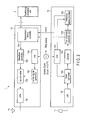
- FIG. 2 is a functional block diagram showing an example of the transmitter apparatus 1 shown in FIG. 1 .
- the transmitter apparatus 1 includes the GPS receiver 12, the signal transmitter 13, and a master clock 15.
- the GPS receiver 12 the GPS signal picked up by the GPS antenna 11 is amplified by a low noise amplifier (LNA) 121.
- the amplified GPS signal is down-converted by a down converter 122 and decoded by a decoder 124.
- LNA low noise amplifier
- a time information acquisition unit 125 acquires a time stamp from the decoded GPS signal.
- a reference signal generator 126 generates a 1PPS signal based on the acquired time stamp.
- a precision clock from the master clock 15 is multiplied by N by a multiplier 123 and given to the down converter 122 and the reference signal generator 126.
- the signal transmitter 13 includes a transmission timing controller 131, a waveform generator 132, an up converter 133, a multiplier 134, a carrier signal generator 135, a high power amplifier (HPA) 136, and the transmission antenna 14.
- the transmission timing controller 131 generates a transmission timing based on the 1PPS signal output from the GPS receiver 12.
- the waveform generator 132 generates a transmission signal having a pulsed waveform at the transmission timing given by the transmission timing controller 131.
- the multiplier 134 gives the carrier signal generator 135 a clock generated by multiplying the precision clock from the master clock 15 by N.
- the carrier signal generator 135 generates a carrier signal using the given clock, and supplies the carrier signal to the up converter 133.
- the up converter 133 up-converts the transmission signal from the waveform generator 132 to the radio frequency band using the supplied carrier signal.
- the transmission signal converted into the radio frequency is power-amplified by the high power amplifier (HPA) 136 and transmitted from the transmission antenna 14 as a radio wave.
- the transmission timing controller 131 notifies the positioning processor unit 3 of the radio wave transmission time using the time stamp from the GPS receiver 12.
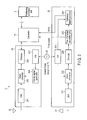
- FIG. 3 is a functional block diagram showing an example of the receiver apparatus 2 shown in FIG. 1 .
- the receiver apparatus 2 includes the GPS receiver 22, the signal receiver 24, and a master clock 26.
- the GPS receiver 22 the GPS signal picked up by the GPS antenna 21 is amplified by a low noise amplifier (LNA) 221.
- the amplified GPS signal is frequency-converted by a down converter 222 and decoded by a decoder 224.
- LNA low noise amplifier
- a time information acquisition unit 225 acquires a time stamp from the decoded GPS signal.
- a reference signal generator 226 generates a 1PPS signal based on the acquired time stamp.
- a precision clock from the master clock 26 is multiplied by N by a multiplier 223 and given to the down converter 222 and the reference signal generator 226.
- the signal receiver 24 includes the receiving antenna 23, a low noise amplifier (LNA) 241, a down converter 242, a multiplier 243, a carrier signal generator 244, and the detector 245.
- LNA low noise amplifier
- a reflected wave from a target is picked up by the receiving antenna 23 and converted into an excitation signal.
- the excitation signal is amplified by the low noise amplifier (LNA) 241 and output to the down converter 242.
- LNA low noise amplifier
- the carrier signal generator 244 generates a carrier signal using the clock from the multiplier 243, which is derived from the precision clock of the master clock 26, and supplies the carrier signal to the down converter 242.
- the down converter 242 down-converts the reception signal into a predetermined frequency (for example, baseband) using the supplied carrier signal.
- the detector 245 detects the output from the down converter 242, and outputs the detected reception signal to the calculator 25.
- time synchronization in the respective sites is essential.
- the master clocks 15 and 26 are shared by the signal transmitter 13, the signal receiver 24, and the GPS receivers 12 and 22.
- the common master clocks are used for up conversion in the signal transmitter 13, down conversion in the signal receiver 24, and GPS observation.
- a rubidium oscillator or cesium oscillator is used as the master clocks 15 and 26. This can implement a frequency accuracy (about 1 ⁇ 10 -10 ) higher than a normal oven-controlled crystal oscillator (OCXO).
- FIG. 4 is a view for explaining a Doppler frequency.
- the calculator 25 receives a pulse to be tracked, and calculates a Doppler frequency and a next assumed time difference ⁇ ta.
- the Doppler frequency ⁇ f is positive (+) in the direction from a receiver apparatus Rx to a target T.
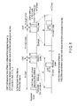
- FIG. 5 is a timing chart for explaining a time filter setting method.
- the assumed reception time of the next pulse is estimated from the reception time of the first pulse to be tracked.
- the assumed reception time of the second pulse is represented by "A (transmission time interval) + ⁇ ta1".
- the detector 245 sets a time filter interval B with respect to the assumed reception time "A + ⁇ ta1" of the second pulse as the center. That is, the gate of a time width B is set. The next pulse (second pulse) is received within the period of the gate.
- the next assumed time difference ⁇ ta2 is calculated from the Doppler frequency of the second pulse.
- a time difference ⁇ tb between the assumed radio wave arrival time and the actual radio wave arrival time is calculated from the difference between the assumed reception time "A + ⁇ ta1" and the actual reception time of the second pulse.
- the assumed reception time is set to A + ⁇ ta + ⁇ tb.
- the assumed reception time of the third pulse is A + ⁇ ta2 + ⁇ tb2. That is, from the reception time of the third pulse, ⁇ ta and ⁇ tb are estimated from the immediately preceding received pulse, and the next assumed pulse reception time is set.
- the embodiment it is possible to implement a positioning system capable of raising the received pulse observation accuracy and efficiently tracking a target.
- the radio wave transmission timing is generated using the 1PPS signal radiated from the GPS satellite, time error components at each site can be reduced, and the time difference at each site can be made very small.
- the present invention is not limited to the above embodiment.
- a bi-static system and a multi-static system have been exemplified in the embodiment.
- the concept of the present invention is applicable not only to these systems but also to an MLAT (Multi-lateration system) having the same reception method.
- the time accuracy can be improved by using a high-performance master clock and sharing the clock in the signal receiver and the GPS receiver. It is therefore possible to improve the target observation accuracy.
Abstract
Description
- Embodiments described herein relate generally to a positioning system and method for estimating the position of a target such as an aircraft.
- A Multi-Static Primary Surveillance Radar (MSPSR) includes a transmitter and a plurality of receivers. The transmitter radiates a pulsed radio wave. Each receiver receives a reflected wave (echo signal) returned from a target. The position (range) of the target can be estimated by performing elliptical positioning for each receiver based on the time difference between transmission and reception. The target can be specified by hyperbolic positioning between a plurality of transmission/reception channels using the combinations of the transmitter and the receivers.
- In some cases, the receiver cannot correctly receive the reflected wave because of the reception environment, reception sensitivity, or the like. This leads to deterioration of the observation accuracy and tracking performance and errors in position estimation. It is demanded to cope with these problems.
-
-
FIG. 1 is a view showing an example of a positioning system according to an embodiment; -
FIG. 2 is a functional block diagram showing an example of atransmitter apparatus 1 shown inFIG. 1 ; -
FIG. 3 is a functional block diagram showing an example of areceiver apparatus 2 shown inFIG. 1 ; -
FIG. 4 is a view for explaining a Doppler frequency; and -
FIG. 5 is a timing chart for explaining a time filter setting method. - In general, according to one embodiment, a positioning system includes a transmitter apparatus and a receiver apparatus. The transmitter apparatus transmits a radio wave. The receiver apparatus receives a reflected wave from a target. The transmitter apparatus comprises a first GPS receiver and a transmitter. The first GPS receiver receives a GPS (Global Positioning System) signal and outputs a reference signal. The transmitter transmits the radio wave at a predetermined time interval based on the reference signal. The receiver apparatus includes a second GPS receiver, a detector, a Doppler frequency calculator, and an arrival time difference calculator. The second GPS receiver receives the GPS signal and outputs time information. The detector receives the reflected wave and outputs a reception signal to which the received time information is added. The Doppler frequency calculator calculates a Doppler frequency based on a reception frequency of the reception signal and a transmission frequency of the radio wave. The arrival time difference calculator calculates an arrival time difference of the reflected wave based on the Doppler frequency. The detector sets a time filter to receive a next pulse based on the arrival time difference and the time information added to the reception signal.
- Various embodiments will be described hereinafter with reference to the accompanying drawings.
-
FIG. 1 is a view showing an example of a positioning system according to an embodiment. This positioning system includes atransmitter apparatus 1, areceiver apparatus 2, and apositioning processor unit 3. Thetransmitter apparatus 1 and thereceiver apparatus 2 are communicably connected to thepositioning processor unit 3 via a network. Thetransmitter apparatus 1 transmits a pulsed radio wave to a target. Thereceiver apparatus 2 receives a reflected wave from the target. Thepositioning processor unit 3 estimates the position of the target. - A system including the
transmitter apparatus 1 and thereceiver apparatus 2 is a so-called bi-static system. A system having a plurality of combinations of thetransmitter apparatus 1 and thereceiver apparatuses 2 is a so-called multi-static system. A bi-static system will be described here for the sake of simplicity. - The
transmitter apparatus 1 includes a GPS (Global Positioning System)antenna 11, aGPS receiver 12, asignal transmitter 13, and atransmission antenna 14. TheGPS receiver 12 receives a GPS signal from a GPS satellite by theGPS antenna 11, and outputs a time stamp and a 1PPS (Pulse Per Second) signal to thesignal transmitter 13. In many cases, the time stamp corresponds to the time at which the GPS signal is received. - The
signal transmitter 13 radiates radio waves from thetransmission antenna 14 at a predetermined time interval. The radio wave transmission timing is controlled based on the 1PPS signal output from theGPS receiver 12. Thesignal transmitter 13 notifies thepositioning processor unit 3 of the radio wave transmission time using the time stamp. - The 1PPS signal is a reference signal transmitted from the GPS satellite once a second, and is used as the radio wave transmission time synchronization signal of the
signal transmitter 13. The accuracy of the 1PPS signal depends on the time accuracy of the GPS satellite. Since the time accuracy of the GPS satellite is very high, the time accuracy of the 1PPS signal is very high as well. When the 1PPS signal serves as a time correction signal in theGPS receiver 12, an accurate time stamp can be output. - The
receiver apparatus 2 includes aGPS antenna 21, aGPS receiver 22, a receivingantenna 23, asignal receiver 24, and acalculator 25. TheGPS receiver 22 receives a GPS signal from a GPS satellite by theGPS antenna 21, and outputs a time stamp and a 1PPS signal to thesignal receiver 24, like theGPS receiver 12. - The receiving
antenna 23 of thesignal receiver 24 catches a reflected wave from a target and outputs an excitation signal. Adetector 245 detects the excitation signal and generates a reception signal. Thedetector 245 also adds reception time information to the reception signal using a time stamp from theGPS receiver 22. - The
calculator 25 calculates a Doppler velocity component (including a Doppler frequency) based on the difference between the frequency of the reception signal and the frequency of the transmission wave using the frequency information of the frequency information sent from thesignal receiver 24. Thecalculator 25 also estimates, based on the Doppler velocity component, time information at which the reflected wave from the target arrives next. Additionally, thecalculator 25 measures the difference (arrival time difference) between the estimated arrival time and the actual pulse arrival time. The measured arrival time difference is sent to thedetector 245 in thesignal receiver 24 as arrival time difference information. - The
positioning processor unit 3 receives the Doppler velocity component calculated by thecalculator 25 and the time stamp added to the reception signal from thereceiver apparatus 2 via the network. Thepositioning processor unit 3 estimates the position of the target by elliptical positioning using two focal points based on the transmission time information (time stamp) and the reception time information (time stamp). - The
detector 245 of thesignal receiver 24 receives the arrival time difference information from thecalculator 25. Using the arrival time difference information, thedetector 245 sets the time at which the next pulse arrives and performs reception processing by applying a time filter. Thedetector 245 calculates a time difference (preceding time difference) from previously received radio wave arrival time information, and uses the preceding time difference as a setting parameter of the time filter. Details of setting of the time filter will be described later. -
FIG. 2 is a functional block diagram showing an example of thetransmitter apparatus 1 shown inFIG. 1 . Thetransmitter apparatus 1 includes theGPS receiver 12, thesignal transmitter 13, and amaster clock 15. In theGPS receiver 12, the GPS signal picked up by theGPS antenna 11 is amplified by a low noise amplifier (LNA) 121. The amplified GPS signal is down-converted by adown converter 122 and decoded by adecoder 124. - A time
information acquisition unit 125 acquires a time stamp from the decoded GPS signal. Areference signal generator 126 generates a 1PPS signal based on the acquired time stamp. A precision clock from themaster clock 15 is multiplied by N by amultiplier 123 and given to thedown converter 122 and thereference signal generator 126. - The
signal transmitter 13 includes atransmission timing controller 131, awaveform generator 132, an upconverter 133, amultiplier 134, acarrier signal generator 135, a high power amplifier (HPA) 136, and thetransmission antenna 14. - The
transmission timing controller 131 generates a transmission timing based on the 1PPS signal output from theGPS receiver 12. Thewaveform generator 132 generates a transmission signal having a pulsed waveform at the transmission timing given by thetransmission timing controller 131. Themultiplier 134 gives the carrier signal generator 135 a clock generated by multiplying the precision clock from themaster clock 15 by N. Thecarrier signal generator 135 generates a carrier signal using the given clock, and supplies the carrier signal to the upconverter 133. - The up
converter 133 up-converts the transmission signal from thewaveform generator 132 to the radio frequency band using the supplied carrier signal. The transmission signal converted into the radio frequency is power-amplified by the high power amplifier (HPA) 136 and transmitted from thetransmission antenna 14 as a radio wave. Thetransmission timing controller 131 notifies thepositioning processor unit 3 of the radio wave transmission time using the time stamp from theGPS receiver 12. -
FIG. 3 is a functional block diagram showing an example of thereceiver apparatus 2 shown inFIG. 1 . Thereceiver apparatus 2 includes theGPS receiver 22, thesignal receiver 24, and amaster clock 26. In theGPS receiver 22, the GPS signal picked up by theGPS antenna 21 is amplified by a low noise amplifier (LNA) 221. The amplified GPS signal is frequency-converted by adown converter 222 and decoded by adecoder 224. - A time
information acquisition unit 225 acquires a time stamp from the decoded GPS signal. Areference signal generator 226 generates a 1PPS signal based on the acquired time stamp. A precision clock from themaster clock 26 is multiplied by N by amultiplier 223 and given to thedown converter 222 and thereference signal generator 226. - The
signal receiver 24 includes the receivingantenna 23, a low noise amplifier (LNA) 241, adown converter 242, amultiplier 243, acarrier signal generator 244, and thedetector 245. - A reflected wave from a target is picked up by the receiving
antenna 23 and converted into an excitation signal. The excitation signal is amplified by the low noise amplifier (LNA) 241 and output to thedown converter 242. - The
carrier signal generator 244 generates a carrier signal using the clock from themultiplier 243, which is derived from the precision clock of themaster clock 26, and supplies the carrier signal to thedown converter 242. The downconverter 242 down-converts the reception signal into a predetermined frequency (for example, baseband) using the supplied carrier signal. Thedetector 245 detects the output from thedown converter 242, and outputs the detected reception signal to thecalculator 25. - In the positioning system, time synchronization in the respective sites (transmission site and reception site) is essential. In the above-described arrangement, the master clocks 15 and 26 are shared by the
signal transmitter 13, thesignal receiver 24, and theGPS receivers - That is, the common master clocks are used for up conversion in the
signal transmitter 13, down conversion in thesignal receiver 24, and GPS observation. A rubidium oscillator or cesium oscillator is used as the master clocks 15 and 26. This can implement a frequency accuracy (about 1 × 10⁻¹⁰) higher than a normal oven-controlled crystal oscillator (OCXO). - This makes it possible to reduce phase errors and time errors between the
GPS receiver 12 and thesignal transmitter 13 and reduce phase errors and time errors between theGPS receiver 22 and thesignal receiver 24. When the radio wave transmission timing is generated using the 1PPS signal radiated from the GPS satellite, time errors of radio waves radiated from each site can be reduced. Note that in a case where the time of the transmission site and the time of the reception site synchronize, and the radio wave transmission time interval is predetermined, transmission time information can be added to the reception signal on the receiver apparatus side. Setting of a time filter will be described next in detail with reference toFIGS. 4 and5 . -
FIG. 4 is a view for explaining a Doppler frequency. Thecalculator 25 receives a pulse to be tracked, and calculates a Doppler frequency and a next assumed time difference Δta. As shown inFIG. 4 , the Doppler frequency Δf is positive (+) in the direction from a receiver apparatus Rx to a target T. For example, the Doppler frequency is given by
- fRx: reception frequency of the reflected wave from the target in the receiver apparatus Rx
- fT: transmission frequency (known) of the radio wave that has arrived from the target T
-
FIG. 5 is a timing chart for explaining a time filter setting method. First, the assumed reception time of the next pulse is estimated from the reception time of the first pulse to be tracked. The assumed reception time of the second pulse is represented by "A (transmission time interval) + Δta1". Using the Doppler frequency Δf, the next assumed time difference Δta can be obtained by
- The
detector 245 sets a time filter interval B with respect to the assumed reception time "A + Δta1" of the second pulse as the center. That is, the gate of a time width B is set. The next pulse (second pulse) is received within the period of the gate. - The next assumed time difference Δta2 is calculated from the Doppler frequency of the second pulse. In addition, a time difference Δtb between the assumed radio wave arrival time and the actual radio wave arrival time is calculated from the difference between the assumed reception time "A + Δta1" and the actual reception time of the second pulse.
- From the third pulse, the assumed reception time is set to A + Δta + Δtb. The assumed reception time of the third pulse is A + Δta2 + Δtb2. That is, from the reception time of the third pulse, Δta and Δtb are estimated from the immediately preceding received pulse, and the next assumed pulse reception time is set.
- It is possible to track a received pulse and improve the pulse observation accuracy by repeating the above-described process. It is also possible to improve the reflected wave observation accuracy and remove the influence of a direct wave that arrives from the transmitter apparatus by using the time filter.
- Hence, according to the embodiment, it is possible to implement a positioning system capable of raising the received pulse observation accuracy and efficiently tracking a target. When the radio wave transmission timing is generated using the 1PPS signal radiated from the GPS satellite, time error components at each site can be reduced, and the time difference at each site can be made very small.
- Note that the present invention is not limited to the above embodiment. For example, a bi-static system and a multi-static system have been exemplified in the embodiment. However, the concept of the present invention is applicable not only to these systems but also to an MLAT (Multi-lateration system) having the same reception method. In the MLAT as well, the time accuracy can be improved by using a high-performance master clock and sharing the clock in the signal receiver and the GPS receiver. It is therefore possible to improve the target observation accuracy.
- While certain embodiments have been described, these embodiments have been presented by way of example only, and are not intended to limit the scope of the inventions. Indeed, the novel embodiments described herein may be embodied in a variety of other forms; furthermore, various omissions, substitutions and changes in the form of the embodiments described herein may be made without departing from the spirit of the inventions. The accompanying claims and their equivalents are intended to cover such forms or modifications as would fall within the scope and spirit of the inventions.
Claims (6)
- A positioning system comprising:a transmitter apparatus (1) configured to transmit a radio wave; anda receiver apparatus (2) configured to receive a reflected wave from a target, characterized in thatthe transmitter apparatus (1) comprises:a GPS receiver (12) configured to receive a GPS (Global Positioning System) signal and output a reference signal; anda transmitter (13) configured to transmit the radio wave at a predetermined time interval based on the reference signal,the receiver apparatus (2) comprises:a GPS receiver (22) configured to receive the GPS signal and output time information;a detector (24) configured to receive the reflected wave and output a reception signal to which the received time information is added;a Doppler frequency calculator (25) configured to calculate a Doppler frequency based on a reception frequency of the reception signal and a transmission frequency of the radio wave; andan arrival time difference calculator (25) configured to calculate an arrival time difference of the reflected wave based on the Doppler frequency, andthe detector (24) sets a time filter to receive a next pulse based on the arrival time difference and the time information added to the reception signal.
- The positioning system according to claim 1, characterized in that a same master clock (15) is used in the first GPS receiver (12) and the transmitter (13) to share a reference clock.
- The positioning system according to claim 1, characterized in that a same master clock (26) is used in the second GPS receiver (22) and the detector (24) to share a reference clock.
- A positioning method of causing a transmitter apparatus (1) to transmit a radio wave, causing a receiver apparatus (2) to receive a reflected wave from a target, and specifying a position of the target, the method comprising:receiving a GPS (Global Positioning System) signal and outputting a reference signal by the transmitter apparatus (1) ;transmitting the radio wave at a predetermined time interval based on the reference signal by the transmitter apparatus (1);receiving the GPS signal and outputting time information by the receiver apparatus (2);receiving the reflected wave and outputting a reception signal to which the received time information is added, by the receiver apparatus (2);calculating a Doppler frequency from a reception frequency of the reception signal and a transmission frequency of the radio wave by the receiver apparatus (2);calculating an arrival time difference of the reflected wave from the Doppler frequency by the receiver apparatus (2); andsetting by the receiver apparatus (2) a time filter to receive a next pulse based on the arrival time difference and the time information added to the reception signal.
- The positioning method according to claim 4, characterized by further comprising using the same master clock (15) in the receiving by the transmitter apparatus (1) and the transmitting by the transmitter apparatus (1) to share a reference clock.
- The positioning method according to claim 4, characterized by further comprising using the same master clock (26) in the receiving the GPS signal by the receiver apparatus (2) and the receiving the reflected wave by the receiver apparatus (2) to share a reference clock.
Applications Claiming Priority (1)
| Application Number | Priority Date | Filing Date | Title |
|---|---|---|---|
| JP2014039136A JP6081394B2 (en) | 2014-02-28 | 2014-02-28 | Positioning system and positioning method |
Publications (2)
| Publication Number | Publication Date |
|---|---|
| EP2913690A1 true EP2913690A1 (en) | 2015-09-02 |
| EP2913690B1 EP2913690B1 (en) | 2017-02-08 |
Family
ID=50982848
Family Applications (1)
| Application Number | Title | Priority Date | Filing Date |
|---|---|---|---|
| EP14174729.5A Active EP2913690B1 (en) | 2014-02-28 | 2014-06-27 | Positioning system and method |
Country Status (3)
| Country | Link |
|---|---|
| US (1) | US9733352B2 (en) |
| EP (1) | EP2913690B1 (en) |
| JP (1) | JP6081394B2 (en) |
Cited By (1)
| Publication number | Priority date | Publication date | Assignee | Title |
|---|---|---|---|---|
| EP3648517A4 (en) * | 2017-06-30 | 2020-07-08 | Sony Semiconductor Solutions Corporation | Wireless terminal, information processing device, information processing method, and program |
Families Citing this family (3)
| Publication number | Priority date | Publication date | Assignee | Title |
|---|---|---|---|---|
| US10809384B2 (en) * | 2017-02-09 | 2020-10-20 | Jackson Labs Technologies, Inc. | Method and apparatus to retrofit legacy global positioning satellite (GPS) and other global navigation satellite system (GNSS) receivers |
| CN109188380B (en) * | 2018-09-12 | 2021-11-02 | 北京机械设备研究所 | Key index testing system and method for low-slow small detection radar |
| CN117289256B (en) * | 2023-11-24 | 2024-01-30 | 成都本原星通科技有限公司 | Target long-distance high-precision tracking method based on low-orbit communication satellite |
Citations (3)
| Publication number | Priority date | Publication date | Assignee | Title |
|---|---|---|---|---|
| GB2250154A (en) * | 1990-11-21 | 1992-05-27 | Roke Manor Research | Object locating system |
| US5359575A (en) * | 1993-09-08 | 1994-10-25 | The Laitram Corporation | Underwater pulse tracking system |
| WO2008058770A1 (en) * | 2006-11-17 | 2008-05-22 | Sony Ericsson Mobile Communications Ab | Mobile electronic device equipped with a radar |
Family Cites Families (14)
| Publication number | Priority date | Publication date | Assignee | Title |
|---|---|---|---|---|
| JPS58200179A (en) * | 1982-05-17 | 1983-11-21 | Unyusho Senpaku Gijutsu Kenkyusho | Unidirectional measuring apparatus for distance |
| JPH0365992U (en) * | 1989-10-31 | 1991-06-26 | ||
| JP2962983B2 (en) | 1993-12-09 | 1999-10-12 | 防衛庁技術研究本部長 | CW Doppler measurement radar device |
| JP3040984B1 (en) * | 1999-02-12 | 2000-05-15 | 三菱電機株式会社 | Bistatic radar system |
| AU2002256451B2 (en) | 2001-05-04 | 2008-05-01 | Lockheed Martin Corporation | System and method for measurment domain data association in passive coherent location applications |
| US6710743B2 (en) * | 2001-05-04 | 2004-03-23 | Lockheed Martin Corporation | System and method for central association and tracking in passive coherent location applications |
| JP5002888B2 (en) * | 2004-10-08 | 2012-08-15 | 日本電気株式会社 | Multi-radar system and control method thereof |
| FR2882442B1 (en) * | 2005-02-18 | 2007-04-20 | Thales Sa | METHOD FOR THE DETECTION IN BI-STATIC MODE BY PASSIVE EXPLOITATION OF NON-COOPERATIVE RADIO EMISSIONS |
| JP5669168B2 (en) * | 2009-03-05 | 2015-02-12 | 日本電気株式会社 | Distance measuring system and distance measuring method |
| JP5056785B2 (en) * | 2009-03-26 | 2012-10-24 | 日本電気株式会社 | Aircraft position measurement system, receiving station, aircraft position measurement method and program |
| JP2014002109A (en) * | 2012-06-20 | 2014-01-09 | Toshiba Corp | Passive radar system, passive radar receiver and target detection program |
| JP5976413B2 (en) * | 2012-06-22 | 2016-08-23 | 株式会社東芝 | Radar system, transmitter, receiver and radar system transmission / reception method |
| JP5865794B2 (en) * | 2012-07-13 | 2016-02-17 | 三菱電機株式会社 | Radar equipment |
| JP6068067B2 (en) | 2012-09-06 | 2017-01-25 | 日本碍子株式会社 | Plugged honeycomb structure |
-
2014
- 2014-02-28 JP JP2014039136A patent/JP6081394B2/en active Active
- 2014-06-27 EP EP14174729.5A patent/EP2913690B1/en active Active
- 2014-07-02 US US14/321,939 patent/US9733352B2/en active Active
Patent Citations (3)
| Publication number | Priority date | Publication date | Assignee | Title |
|---|---|---|---|---|
| GB2250154A (en) * | 1990-11-21 | 1992-05-27 | Roke Manor Research | Object locating system |
| US5359575A (en) * | 1993-09-08 | 1994-10-25 | The Laitram Corporation | Underwater pulse tracking system |
| WO2008058770A1 (en) * | 2006-11-17 | 2008-05-22 | Sony Ericsson Mobile Communications Ab | Mobile electronic device equipped with a radar |
Cited By (1)
| Publication number | Priority date | Publication date | Assignee | Title |
|---|---|---|---|---|
| EP3648517A4 (en) * | 2017-06-30 | 2020-07-08 | Sony Semiconductor Solutions Corporation | Wireless terminal, information processing device, information processing method, and program |
Also Published As
| Publication number | Publication date |
|---|---|
| US9733352B2 (en) | 2017-08-15 |
| US20150247929A1 (en) | 2015-09-03 |
| JP2015161679A (en) | 2015-09-07 |
| JP6081394B2 (en) | 2017-02-15 |
| EP2913690B1 (en) | 2017-02-08 |
Similar Documents
| Publication | Publication Date | Title |
|---|---|---|
| KR102132152B1 (en) | Method and system of timing and localizing a radio signal | |
| CN107682053B (en) | Satellite communication Doppler frequency shift compensation method and device and satellite communication system | |
| US11016169B2 (en) | Method and system for reducing interference caused by phase noise in a radar system | |
| CA2855644C (en) | A chirp receiver utilizing phase precessed chirp signals | |
| EP3531164A1 (en) | Phase synchronization method and device and storage medium | |
| CA3016332A1 (en) | Position estimation in a low earth orbit satellite communications system | |
| CN114706063A (en) | Method in a radar system, radar system or arrangement of radar systems | |
| US9733352B2 (en) | Positioning system and method | |
| AU2015292265B2 (en) | Method and device for chronologically synchronizing a kinematic location network | |
| WO2009124283A2 (en) | A method and system of a mobile subscriber estimating position | |
| WO2013010123A1 (en) | System and method for enhanced point-to-point direction finding | |
| JP6324327B2 (en) | Passive radar equipment | |
| US9797987B2 (en) | Correcting frequency errors in frequency difference of arrival geolocation systems | |
| US9184786B2 (en) | Systems and methods for clock calibration for satellite navigation | |
| JP6130195B2 (en) | Radar system | |
| CN110488229B (en) | Time-frequency space-synchronization method for double-multi-base forward-looking imaging | |
| RU2631422C1 (en) | Correlation-phase direction-finder | |
| JP5976413B2 (en) | Radar system, transmitter, receiver and radar system transmission / reception method | |
| JP2006105897A (en) | Multi-radar system and its controlling method | |
| CN108226916B (en) | Frequency stepping signal speed compensation system based on difference frequency double waveforms | |
| JP6403704B2 (en) | Positioning device | |
| US7327314B2 (en) | Two-way ranging between radio transceivers | |
| US8054863B2 (en) | Ranging system and method | |
| RU2585325C1 (en) | System for synchronising frequency and time scale of remote stations | |
| RU2589036C1 (en) | Radar with continuous noise signal and method of extending range of measured distances in radar with continuous signal |
Legal Events
| Date | Code | Title | Description |
|---|---|---|---|
| PUAI | Public reference made under article 153(3) epc to a published international application that has entered the european phase |
Free format text: ORIGINAL CODE: 0009012 |
|
| 17P | Request for examination filed |
Effective date: 20140627 |
|
| AK | Designated contracting states |
Kind code of ref document: A1 Designated state(s): AL AT BE BG CH CY CZ DE DK EE ES FI FR GB GR HR HU IE IS IT LI LT LU LV MC MK MT NL NO PL PT RO RS SE SI SK SM TR |
|
| AX | Request for extension of the european patent |
Extension state: BA ME |
|
| GRAP | Despatch of communication of intention to grant a patent |
Free format text: ORIGINAL CODE: EPIDOSNIGR1 |
|
| RIC1 | Information provided on ipc code assigned before grant |
Ipc: G01S 19/03 20100101ALI20160805BHEP Ipc: G01S 13/06 20060101ALI20160805BHEP Ipc: G01S 7/02 20060101AFI20160805BHEP Ipc: G01S 7/40 20060101ALI20160805BHEP Ipc: G01S 13/86 20060101ALI20160805BHEP Ipc: G01S 13/02 20060101ALI20160805BHEP Ipc: G01S 7/28 20060101ALI20160805BHEP Ipc: G01S 13/58 20060101ALI20160805BHEP Ipc: G01S 13/18 20060101ALI20160805BHEP Ipc: G01S 13/00 20060101ALI20160805BHEP Ipc: G01S 13/70 20060101ALI20160805BHEP |
|
| INTG | Intention to grant announced |
Effective date: 20160825 |
|
| GRAS | Grant fee paid |
Free format text: ORIGINAL CODE: EPIDOSNIGR3 |
|
| STAA | Information on the status of an ep patent application or granted ep patent |
Free format text: STATUS: GRANT OF PATENT IS INTENDED |
|
| GRAA | (expected) grant |
Free format text: ORIGINAL CODE: 0009210 |
|
| STAA | Information on the status of an ep patent application or granted ep patent |
Free format text: STATUS: THE PATENT HAS BEEN GRANTED |
|
| AK | Designated contracting states |
Kind code of ref document: B1 Designated state(s): AL AT BE BG CH CY CZ DE DK EE ES FI FR GB GR HR HU IE IS IT LI LT LU LV MC MK MT NL NO PL PT RO RS SE SI SK SM TR |
|
| REG | Reference to a national code |
Ref country code: GB Ref legal event code: FG4D |
|
| REG | Reference to a national code |
Ref country code: CH Ref legal event code: EP Ref country code: AT Ref legal event code: REF Ref document number: 867109 Country of ref document: AT Kind code of ref document: T Effective date: 20170215 |
|
| REG | Reference to a national code |
Ref country code: IE Ref legal event code: FG4D |
|
| REG | Reference to a national code |
Ref country code: DE Ref legal event code: R096 Ref document number: 602014006688 Country of ref document: DE |
|
| REG | Reference to a national code |
Ref country code: SE Ref legal event code: TRGR |
|
| REG | Reference to a national code |
Ref country code: LT Ref legal event code: MG4D |
|
| REG | Reference to a national code |
Ref country code: NL Ref legal event code: MP Effective date: 20170208 |
|
| REG | Reference to a national code |
Ref country code: AT Ref legal event code: MK05 Ref document number: 867109 Country of ref document: AT Kind code of ref document: T Effective date: 20170208 |
|
| PG25 | Lapsed in a contracting state [announced via postgrant information from national office to epo] |
Ref country code: FI Free format text: LAPSE BECAUSE OF FAILURE TO SUBMIT A TRANSLATION OF THE DESCRIPTION OR TO PAY THE FEE WITHIN THE PRESCRIBED TIME-LIMIT Effective date: 20170208 Ref country code: HR Free format text: LAPSE BECAUSE OF FAILURE TO SUBMIT A TRANSLATION OF THE DESCRIPTION OR TO PAY THE FEE WITHIN THE PRESCRIBED TIME-LIMIT Effective date: 20170208 Ref country code: LT Free format text: LAPSE BECAUSE OF FAILURE TO SUBMIT A TRANSLATION OF THE DESCRIPTION OR TO PAY THE FEE WITHIN THE PRESCRIBED TIME-LIMIT Effective date: 20170208 Ref country code: NO Free format text: LAPSE BECAUSE OF FAILURE TO SUBMIT A TRANSLATION OF THE DESCRIPTION OR TO PAY THE FEE WITHIN THE PRESCRIBED TIME-LIMIT Effective date: 20170508 Ref country code: GR Free format text: LAPSE BECAUSE OF FAILURE TO SUBMIT A TRANSLATION OF THE DESCRIPTION OR TO PAY THE FEE WITHIN THE PRESCRIBED TIME-LIMIT Effective date: 20170509 |
|
| PG25 | Lapsed in a contracting state [announced via postgrant information from national office to epo] |
Ref country code: LV Free format text: LAPSE BECAUSE OF FAILURE TO SUBMIT A TRANSLATION OF THE DESCRIPTION OR TO PAY THE FEE WITHIN THE PRESCRIBED TIME-LIMIT Effective date: 20170208 Ref country code: NL Free format text: LAPSE BECAUSE OF FAILURE TO SUBMIT A TRANSLATION OF THE DESCRIPTION OR TO PAY THE FEE WITHIN THE PRESCRIBED TIME-LIMIT Effective date: 20170208 Ref country code: PT Free format text: LAPSE BECAUSE OF FAILURE TO SUBMIT A TRANSLATION OF THE DESCRIPTION OR TO PAY THE FEE WITHIN THE PRESCRIBED TIME-LIMIT Effective date: 20170608 Ref country code: ES Free format text: LAPSE BECAUSE OF FAILURE TO SUBMIT A TRANSLATION OF THE DESCRIPTION OR TO PAY THE FEE WITHIN THE PRESCRIBED TIME-LIMIT Effective date: 20170208 Ref country code: RS Free format text: LAPSE BECAUSE OF FAILURE TO SUBMIT A TRANSLATION OF THE DESCRIPTION OR TO PAY THE FEE WITHIN THE PRESCRIBED TIME-LIMIT Effective date: 20170208 Ref country code: AT Free format text: LAPSE BECAUSE OF FAILURE TO SUBMIT A TRANSLATION OF THE DESCRIPTION OR TO PAY THE FEE WITHIN THE PRESCRIBED TIME-LIMIT Effective date: 20170208 Ref country code: BG Free format text: LAPSE BECAUSE OF FAILURE TO SUBMIT A TRANSLATION OF THE DESCRIPTION OR TO PAY THE FEE WITHIN THE PRESCRIBED TIME-LIMIT Effective date: 20170508 |
|
| PG25 | Lapsed in a contracting state [announced via postgrant information from national office to epo] |
Ref country code: EE Free format text: LAPSE BECAUSE OF FAILURE TO SUBMIT A TRANSLATION OF THE DESCRIPTION OR TO PAY THE FEE WITHIN THE PRESCRIBED TIME-LIMIT Effective date: 20170208 Ref country code: SK Free format text: LAPSE BECAUSE OF FAILURE TO SUBMIT A TRANSLATION OF THE DESCRIPTION OR TO PAY THE FEE WITHIN THE PRESCRIBED TIME-LIMIT Effective date: 20170208 Ref country code: IT Free format text: LAPSE BECAUSE OF FAILURE TO SUBMIT A TRANSLATION OF THE DESCRIPTION OR TO PAY THE FEE WITHIN THE PRESCRIBED TIME-LIMIT Effective date: 20170208 Ref country code: RO Free format text: LAPSE BECAUSE OF FAILURE TO SUBMIT A TRANSLATION OF THE DESCRIPTION OR TO PAY THE FEE WITHIN THE PRESCRIBED TIME-LIMIT Effective date: 20170208 |
|
| REG | Reference to a national code |
Ref country code: DE Ref legal event code: R097 Ref document number: 602014006688 Country of ref document: DE |
|
| PG25 | Lapsed in a contracting state [announced via postgrant information from national office to epo] |
Ref country code: DK Free format text: LAPSE BECAUSE OF FAILURE TO SUBMIT A TRANSLATION OF THE DESCRIPTION OR TO PAY THE FEE WITHIN THE PRESCRIBED TIME-LIMIT Effective date: 20170208 Ref country code: PL Free format text: LAPSE BECAUSE OF FAILURE TO SUBMIT A TRANSLATION OF THE DESCRIPTION OR TO PAY THE FEE WITHIN THE PRESCRIBED TIME-LIMIT Effective date: 20170208 Ref country code: SM Free format text: LAPSE BECAUSE OF FAILURE TO SUBMIT A TRANSLATION OF THE DESCRIPTION OR TO PAY THE FEE WITHIN THE PRESCRIBED TIME-LIMIT Effective date: 20170208 |
|
| PLBE | No opposition filed within time limit |
Free format text: ORIGINAL CODE: 0009261 |
|
| STAA | Information on the status of an ep patent application or granted ep patent |
Free format text: STATUS: NO OPPOSITION FILED WITHIN TIME LIMIT |
|
| 26N | No opposition filed |
Effective date: 20171109 |
|
| PG25 | Lapsed in a contracting state [announced via postgrant information from national office to epo] |
Ref country code: MC Free format text: LAPSE BECAUSE OF FAILURE TO SUBMIT A TRANSLATION OF THE DESCRIPTION OR TO PAY THE FEE WITHIN THE PRESCRIBED TIME-LIMIT Effective date: 20170208 |
|
| REG | Reference to a national code |
Ref country code: CH Ref legal event code: PL |
|
| PG25 | Lapsed in a contracting state [announced via postgrant information from national office to epo] |
Ref country code: SI Free format text: LAPSE BECAUSE OF FAILURE TO SUBMIT A TRANSLATION OF THE DESCRIPTION OR TO PAY THE FEE WITHIN THE PRESCRIBED TIME-LIMIT Effective date: 20170208 |
|
| REG | Reference to a national code |
Ref country code: FR Ref legal event code: ST Effective date: 20180228 |
|
| REG | Reference to a national code |
Ref country code: IE Ref legal event code: MM4A |
|
| PG25 | Lapsed in a contracting state [announced via postgrant information from national office to epo] |
Ref country code: CH Free format text: LAPSE BECAUSE OF NON-PAYMENT OF DUE FEES Effective date: 20170630 Ref country code: LI Free format text: LAPSE BECAUSE OF NON-PAYMENT OF DUE FEES Effective date: 20170630 Ref country code: LU Free format text: LAPSE BECAUSE OF NON-PAYMENT OF DUE FEES Effective date: 20170627 Ref country code: IE Free format text: LAPSE BECAUSE OF NON-PAYMENT OF DUE FEES Effective date: 20170627 |
|
| PG25 | Lapsed in a contracting state [announced via postgrant information from national office to epo] |
Ref country code: FR Free format text: LAPSE BECAUSE OF NON-PAYMENT OF DUE FEES Effective date: 20170630 |
|
| REG | Reference to a national code |
Ref country code: BE Ref legal event code: MM Effective date: 20170630 |
|
| PG25 | Lapsed in a contracting state [announced via postgrant information from national office to epo] |
Ref country code: BE Free format text: LAPSE BECAUSE OF NON-PAYMENT OF DUE FEES Effective date: 20170630 |
|
| PG25 | Lapsed in a contracting state [announced via postgrant information from national office to epo] |
Ref country code: MT Free format text: LAPSE BECAUSE OF NON-PAYMENT OF DUE FEES Effective date: 20170627 |
|
| GBPC | Gb: european patent ceased through non-payment of renewal fee |
Effective date: 20180627 |
|
| PG25 | Lapsed in a contracting state [announced via postgrant information from national office to epo] |
Ref country code: GB Free format text: LAPSE BECAUSE OF NON-PAYMENT OF DUE FEES Effective date: 20180627 |
|
| PG25 | Lapsed in a contracting state [announced via postgrant information from national office to epo] |
Ref country code: HU Free format text: LAPSE BECAUSE OF FAILURE TO SUBMIT A TRANSLATION OF THE DESCRIPTION OR TO PAY THE FEE WITHIN THE PRESCRIBED TIME-LIMIT; INVALID AB INITIO Effective date: 20140627 |
|
| PG25 | Lapsed in a contracting state [announced via postgrant information from national office to epo] |
Ref country code: CY Free format text: LAPSE BECAUSE OF FAILURE TO SUBMIT A TRANSLATION OF THE DESCRIPTION OR TO PAY THE FEE WITHIN THE PRESCRIBED TIME-LIMIT Effective date: 20170208 |
|
| PG25 | Lapsed in a contracting state [announced via postgrant information from national office to epo] |
Ref country code: MK Free format text: LAPSE BECAUSE OF FAILURE TO SUBMIT A TRANSLATION OF THE DESCRIPTION OR TO PAY THE FEE WITHIN THE PRESCRIBED TIME-LIMIT Effective date: 20170208 |
|
| PG25 | Lapsed in a contracting state [announced via postgrant information from national office to epo] |
Ref country code: TR Free format text: LAPSE BECAUSE OF FAILURE TO SUBMIT A TRANSLATION OF THE DESCRIPTION OR TO PAY THE FEE WITHIN THE PRESCRIBED TIME-LIMIT Effective date: 20170208 |
|
| PG25 | Lapsed in a contracting state [announced via postgrant information from national office to epo] |
Ref country code: AL Free format text: LAPSE BECAUSE OF FAILURE TO SUBMIT A TRANSLATION OF THE DESCRIPTION OR TO PAY THE FEE WITHIN THE PRESCRIBED TIME-LIMIT Effective date: 20170208 Ref country code: IS Free format text: LAPSE BECAUSE OF FAILURE TO SUBMIT A TRANSLATION OF THE DESCRIPTION OR TO PAY THE FEE WITHIN THE PRESCRIBED TIME-LIMIT Effective date: 20170608 |
|
| PGFP | Annual fee paid to national office [announced via postgrant information from national office to epo] |
Ref country code: SE Payment date: 20230314 Year of fee payment: 10 |
|
| PGFP | Annual fee paid to national office [announced via postgrant information from national office to epo] |
Ref country code: DE Payment date: 20230502 Year of fee payment: 10 Ref country code: CZ Payment date: 20230619 Year of fee payment: 10 |