EP2925085A1 - Electric hot water warmer and heating device employing such a warmer - Google Patents
Electric hot water warmer and heating device employing such a warmer Download PDFInfo
- Publication number
- EP2925085A1 EP2925085A1 EP14162137.5A EP14162137A EP2925085A1 EP 2925085 A1 EP2925085 A1 EP 2925085A1 EP 14162137 A EP14162137 A EP 14162137A EP 2925085 A1 EP2925085 A1 EP 2925085A1
- Authority
- EP
- European Patent Office
- Prior art keywords
- warmer
- sealed
- unit
- hot water
- electric hot
- Prior art date
- Legal status (The legal status is an assumption and is not a legal conclusion. Google has not performed a legal analysis and makes no representation as to the accuracy of the status listed.)
- Granted
Links
- 238000010438 heat treatment Methods 0.000 title claims abstract description 78
- XLYOFNOQVPJJNP-UHFFFAOYSA-N water Substances O XLYOFNOQVPJJNP-UHFFFAOYSA-N 0.000 title claims abstract description 78
- 239000007788 liquid Substances 0.000 claims abstract description 49
- 239000000463 material Substances 0.000 claims description 8
- 238000013021 overheating Methods 0.000 claims description 7
- 230000005540 biological transmission Effects 0.000 claims description 3
- 239000004020 conductor Substances 0.000 claims description 3
- 229920001296 polysiloxane Polymers 0.000 claims description 3
- 230000006872 improvement Effects 0.000 description 8
- 230000009471 action Effects 0.000 description 7
- 230000005611 electricity Effects 0.000 description 6
- 230000009286 beneficial effect Effects 0.000 description 5
- 239000004744 fabric Substances 0.000 description 5
- 238000000034 method Methods 0.000 description 5
- 230000008569 process Effects 0.000 description 5
- 230000035945 sensitivity Effects 0.000 description 5
- 230000000694 effects Effects 0.000 description 4
- 238000004880 explosion Methods 0.000 description 4
- 230000006378 damage Effects 0.000 description 3
- 208000027418 Wounds and injury Diseases 0.000 description 2
- 238000005338 heat storage Methods 0.000 description 2
- 208000014674 injury Diseases 0.000 description 2
- 206010000369 Accident Diseases 0.000 description 1
- 230000008859 change Effects 0.000 description 1
- 239000002131 composite material Substances 0.000 description 1
- 238000005520 cutting process Methods 0.000 description 1
- 230000007547 defect Effects 0.000 description 1
- 239000012530 fluid Substances 0.000 description 1
- 238000005286 illumination Methods 0.000 description 1
- 230000005923 long-lasting effect Effects 0.000 description 1
- 238000004519 manufacturing process Methods 0.000 description 1
- 230000009972 noncorrosive effect Effects 0.000 description 1
- 231100000252 nontoxic Toxicity 0.000 description 1
- 230000003000 nontoxic effect Effects 0.000 description 1
- 229920000728 polyester Polymers 0.000 description 1
- 230000000630 rising effect Effects 0.000 description 1
- 238000007789 sealing Methods 0.000 description 1
- 238000000926 separation method Methods 0.000 description 1
Images


Classifications
-
- H—ELECTRICITY
- H05—ELECTRIC TECHNIQUES NOT OTHERWISE PROVIDED FOR
- H05B—ELECTRIC HEATING; ELECTRIC LIGHT SOURCES NOT OTHERWISE PROVIDED FOR; CIRCUIT ARRANGEMENTS FOR ELECTRIC LIGHT SOURCES, IN GENERAL
- H05B1/00—Details of electric heating devices
- H05B1/02—Automatic switching arrangements specially adapted to apparatus ; Control of heating devices
- H05B1/0227—Applications
- H05B1/0252—Domestic applications
- H05B1/0275—Heating of spaces, e.g. rooms, wardrobes
- H05B1/0283—For heating of fluids, e.g. water heaters
-
- H—ELECTRICITY
- H05—ELECTRIC TECHNIQUES NOT OTHERWISE PROVIDED FOR
- H05B—ELECTRIC HEATING; ELECTRIC LIGHT SOURCES NOT OTHERWISE PROVIDED FOR; CIRCUIT ARRANGEMENTS FOR ELECTRIC LIGHT SOURCES, IN GENERAL
- H05B3/00—Ohmic-resistance heating
- H05B3/78—Heating arrangements specially adapted for immersion heating
- H05B3/80—Portable immersion heaters
Abstract
Description
- The present invention relates to the field of heating device, and particularly to an electric hot water warmer and heating device employing such a warmer.
- In the cold winter, many people may use some heating devices to get warm, such as electric warmers. However, such heating devices all need one power supply unit, and therefore the volumes of such heating devices are huger. Obviously, they are not convenient for users to carry, causing the practicalities of the electric warmers are greatly reduced.
- There is still one hot water warmer. The hot water warmer is made of water-proof material to a sealed warmer body, the internal cavity of which is used for storing hot water. When it is used, users need to pour hot water heated in advance into the internal cavity of the hot water warmer. The heat is transmitted to the warmer body through hot water, and then the heat is transmitted to human body through the warmer body, thus heating effect being achieved. However, the hot water in this hot water warmer can not provide heat for a long time. When this hot water warmer is used over a period of time, the heat of the water inside the hot water warmer is gradually dissipating and thus the heating effect is rapidly declined. At this moment, users need to pour the water in the internal cavity out and pour hot water into the hot water warmer again. Therefore, users need to often replace hot water to maintain the heating effect of the hot water warmer, thus the using of which being not convenient. And, in the process of pouring hot water heated in advance into the internal cavity of warmer body, hot water is easily overturned due to manual operation, making human body directly contact with hot water, which easily causes accident that human body is scalded. And the texture of the warmer body is not soft, so it is not beneficial to the contact with human body, influencing the comfort.
- There is occurred a hot water warmer employing electricity to heat in the market now.
- Such hot water warmer is provided with a heat generating tube and equipped with corresponding charging device. But the heat generating tube only has function of generating heat and has no safety function. Once the heating temperature is too high, human body is easily scalded or burned. When serious, dry burning may happen and even the fire happens. The consequence is inconceivable. In addition, the charging device matched with the hot water warmer also has no safety function. When the temperature of the heat generating tube is too high, the charging device is required to be cut off. If the electricity is continued to be provided, the liquid in the hot water warmer may be overheat to expand to a great extent, causing the warmer body being exploded. Once the warmer body is exploded, serious accident that the liquid in the warmer body is splashed will be caused, easily causing human body scalded.
- It is not hard to see that there exists a certain defect in the prior art.
- The invention provides an electric hot water warmer and a heating device incorporating this electric hot water warmer which have anti-dry burning and anti-explosion functions and have advantages of convenient carry, comfort and practicality.
- In order to achieve above described aim, the following technical solutions are employed:
- An electric hot water warmer includes a sealed warmer body, a heating unit and a power unit. A liquid medium for transmitting heat is filled in a sealed cavity inside the sealed warmer body. The total volume of the liquid medium when expanding or vaporized under predetermined temperature corresponds to the normal volume of the liquid medium under room temperature. The heating unit is disposed in the sealed cavity and immersed in the liquid medium. The power unit is sealingly connected with the sealed warmer body. A part of the power unit is exposed in the exterior of the sealed warmer body, and another part thereof is sealed in the sealed cavity of the sealed warmer body. The power unit is electrically connected with the heating unit.
- Further, the heating unit includes a heat generating body, an outer casing and a safety unit. The outer casing is made up of an upper casing and a lower casing. A hollowed-out structure is provided in the outer casing. The heat generating body is disposed in the outer casing and contacts the liquid medium through the hollowed-out structure in the outer casing. A safety unit mounting portion is also provided in the outer casing. The safety unit mounting portion is provided to closely abut to the one side of the heat generating body. The safety unit is mounted in the safety unit mounting portion and is cascaded with the heat generating body. The safety unit is used for providing overheating power-off protection. The safety unit and the heat generating body are then electrically connected with the power unit respectively through wire.
- Further, the safety unit is a fuse.
- Further, the periphery of the safety unit is sealed by silicone.
- Further, the heating unit further includes a spring clip clamping the safety unit and the heat generating body fixed. The spring clip is used for ensuring close abutment between the safety unit and the heat generating body and sufficient heat transmission.
- Further, the spring clip is made of heat conducting material.
- Further, the heat generating body is a heating generating tube.
- The sealed warmer body includes an inner warmer body and an outer warmer body. The inner warmer body is located at the innermost layer of the sealed warmer body and it is made of flexible waterproof material. The sealed cavity formed by the inner warmer body is used to store the liquid medium. The outer warmer body is located at the outermost layer of the sealed warmer body and it is made of flexible material. The outer warmer body is intimately fitted with the outer warmer body. The outer warmer body is used for contact with human body.
- The power unit includes a mounting sleeve, a temperature controlling unit and a socket. The mounting sleeve includes an external portion and an internal portion. The mounting sleeve is sealingly connected with the sealed warmer body. The external portion of the mounting sleeve is exposed to the exterior of the sealed warmer body, and the internal portion of the mounting sleeve is sealed in the sealed cavity of the sealed warmer body. A temperature controlling unit is provided in the internal portion of the mounting sleeve and is cascaded with the heating unit. The temperature controlling unit is used for controlling the conduction and the breakage state of the circuit according to the internal temperature of the electric hot water warmer. The socket is mounted on the external portion of the mounting sleeve and is exposed to the exterior of the sealed warmer body. The socket is electrically connected with the temperature controlling unit and the heating unit, constituting a complete circuit.
- Further, the temperature controlling unit is a temperature controller.
- The power unit further includes an indicator light. The indicator light is mounted on the external portion of the mounting sleeve and is exposed to the exterior of the sealed warmer body. The indicator light is paralleled with the heating unit.
- The power unit further includes a cover. The cover is disposed on the socket and is movably connected with the power unit for controlling the exposure and the closing of the socket.
- A heating device includes aforementioned electric hot water warmer and a charging rack. The charging rack includes a base, a connecting table, a protection device, a charging arm and a power line. The base is used to support the electric hot water warmer thereon. The connecting table is fixed on the base. The connecting table has a hollow structure and the protection device is disposed in the interior thereof. The charging arm has a hollow structure, and has one articulating end and one connecting end. The articulating end of the charging arm is hinged to the upper end of the connecting table. The connecting end of the charging arm is provided with a jack matching with the power unit. The jack is disposed in the electrical circuit inside the connecting arm and is electrically connected with the protection device. One end of the power line is electrically connected with the protection device and the other end is provided with a plug.
- The protection device includes a micro switch. The micro switch is connected between the power line and the jack for controlling the conduction and the breakage of the circuit of the power line and the jack. The micro switch includes a fixed contact and a movable contact. The fixed contact is fixed inside the connecting table of the charging arm and is electrically connected with the power line. The movable contact is fixed to the charging arm and is electrically connected with the jack. The rotation movement of the charging arm around its own articulating end may drive the movable contact to move, thus controlling the connectivity and the disconnectivity of the fixed contact and the movable contact.
- The charging rack further includes an indicator light. The indicator light is mounted on the charging arm and is paralleled with the heating unit through the socket and the jack.
- An electric hot water warmer and a heating device incorporating the electric hot water warmer provided by the invention have the following advantages:
- Having triple protection: power-off protection is performed by a safety unit, the conduction and breakage of the circuit is controlled by a temperature controlling unit, and a protection device prevents the sealed warmer body from expanding to be broken in the process of the charging, completely avoiding potential dry burning and explosion danger and thus having a significant high security;
- A small volume, simple structure and convenient carry;
- The texture of the electric hot water warmer being soft which is beneficial to the contact with human body, comforting the human body.
- In order to more clearly illustrate embodiments of the invention or the technical solutions in the prior art, there is provided a brief introduction to the accompanying drawings which are necessary in the description of the embodiments or the prior art below. Obviously, the drawings described below are only a few embodiments of the invention. For those ordinary skilled in the art, other drawings may be obtained according to these drawings under the premise that creative work is not done.
-
Figure 1 is a structural schematic view of an electric hot water warmer provided by the embodiment of the invention. -
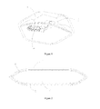
Figure 2 is a structural schematic view of a sealed warmer body. -
Figure 3 is a structural schematic view of a heating unit. -
Figure 4 is a structural schematic view of a power unit. -
Figure 5 is a schematic view of a power unit having another structure. -
Figure 6 is a structural schematic view of a heating device provided by the embodiment of the invention in a normal charged state. -
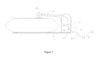
Figure 7 is a structural schematic view of a heating device provided by the embodiment of the invention in a protection device action state. - In order to make the purpose, technical solutions and advantages of the embodiments more clear, the technical solutions in the embodiments of the invention will be described clearly and completely below in combination with the embodiments and drawings of the invention. It should be explained that the described embodiments are only a part of embodiments of the invention not all embodiments. Based on the embodiments of the invention, all other embodiments obtained by those ordinary skilled under the premise that no creative work is done fall in the protection scope of the invention.
- Reference is made to
Figure 1 . An electric hot water warmer includes a sealedwarmer body 1, aheating unit 2 and apower unit 3. A liquid medium for transmitting heat is filled in a sealed cavity 6 inside the sealedwarmer body 1. The total volume of the liquid medium when expanding or vaporized under predetermined temperature corresponds to the normal volume of the liquid medium under room temperature. Theheating unit 2 is disposed in the sealed cavity 6 and immersed in the liquid medium. Thepower unit 3 is sealingly connected with the sealedwarmer body 1. A part of thepower unit 3 is exposed in the exterior of the sealedwarmer body 1, and another part thereof is sealed in the sealed cavity 6 of the sealedwarmer body 1 and immersed in the liquid medium. Thepower unit 3 is electrically connected with theheating unit 2. - The liquid medium may be pure water, and as an improvement, may be a fluid or solution having good heat storage performance, and the liquid medium should be a nontoxic, non-corrosive and safety liquid having no harm to human. It should be explained that there is a difference between different liquid media in the heat storage performance. But no matter which of these liquid media is chosen, they all fall in the protection scope of the invention under the premise that the conception of the invention is not departed.
- The liquid medium when heated to a particular temperature may expand or be vaporized which makes the sealed warmer body 1expand. The liquid medium is generally heated to near 70°C under which the sealed
warmer body 1 expands with respect to the room temperature state about 1-2 centimeters. - Reference is made to
Figure 2 . The sealedwarmer body 1 has two roles: first, providing the sealed cavity 6 for sealing the liquid medium; and second, to be used to directly contact with human body for ensurance of soft, comfort texture. - Further, the sealed
warmer body 1 includes an innerwarmer body 5 and an outerwarmer body 4. The innerwarmer body 5 is located at the innermost layer of the sealedwarmer body 1 and it is made of flexible waterproof material. The sealed cavity 6 formed by the innerwarmer body 5 is used to store the liquid medium. The outerwarmer body 4 is located at the outermost layer of the sealedwarmer body 1 and it is made of flexible material. The outerwarmer body 4 is intimately fitted with the outerwarmer body 5. The outerwarmer body 4 is used for the contact with human body. - Preferably, in the present embodiment, the inner
warmer body 5 is made of PVC film. The PVC film has good waterproof performance and can ensure the seal, preventing the leakage of the liquid medium. Meanwhile the PVC film itself has good softness so that it can change shape following the flow of the liquid medium, which is in favor of users to touch and press the PVC film. And the PVC film has sufficient toughness so that it is safe and practical, widely used in industry and has low production cost. The PVC film is softer and more comfortable than the colloidal warmer body. - Preferably, the outer
warmer body 4 is made of a composite cloth composed of polyester and sponge, and it is weaved to be plush, super soft fabric and other cloth for contact with human body. If the PVC film is simply used, the fabric is rougher. The outerwarmer body 4 made of the cloth can efficiently improve the texture which makes the use of the electric hot water warmer more comfortable. - The
heating unit 2 is used for heating the liquid medium and it is an important component of the electric hot water warmer. Theheating unit 2 makes use of the electric energy to generate heat and the safety thereof is extremely important to the electric hot water warmer. - Reference is made to
Figure 3 . Particularly, theheating unit 2 includes aheat generating body 10, an outer casing 7 and asafety unit 12. - The outer casing 7 is made up of an upper casing 8 and a lower casing 9. A hollowed-out structure is provided in the outer casing 7. The
heat generating body 10 is disposed in the outer casing 7 and contacts the liquid medium through the hollowed-out structure in the outer casing 7. If theheat generating body 10 is simply used for heating the liquid medium, it means theheat generating body 10 can directly contact with the sealedwarmer body 1 during the heating process although the heating function is satisfied. If the temperature of theheat generating body 10 is too high when directly contact with the sealedwarmer body 1, the sealedwarmer body 1 is easily hot melted which causes the sealedwarmer body 1 broken. Or if users press the sealedwarmer body 1 during the use of the electric hot water warmer causing theheat generating body 1 contact with the human body through the sealedwarmer body 1, human body is easily burned resulting in human injury. The outer casing 7 on the one hand plays a part in the safety, and on the other hand can effectively prevent the sealedwarmer body 1 or human body from directly contacting with theheat generating body 10, avoiding accidents. - A safety
unit mounting portion 11 is also provided in the outer casing 7. The safetyunit mounting portion 11 is provided to closely abut to the one side of theheat generating body 10. Thesafety unit 12 is mounted in the safetyunit mounting portion 11 and is cascaded with theheat generating body 10. Thesafety unit 12 is used for providing overheating power-off protection. Thesafety unit 12 and theheat generating body 10 are then electrically connected with thepower unit 3 respectively through wire. Once theheat generating body 10 is overheated, thesafety unit 12 immediately comes into play so that the circuit is broken and theheat generating body 10 stop heating. Overheating of theheat generating body 10 is often seen in the condition that the heating unit is not fully immersed in the liquid medium during the heating process, causing that the heat of theheat generating body 10 is not fully transmitted into the liquid medium, so that theheat generating body 10 is dry burning when continues heating. Or it is often seen in the condition that the liquid medium is overheated, and theheat generating body 10 cannot stop heating, so that the temperature continues to rise. The overheating of theheat generating body 10 is very dangerous, and when serious it can cause the sealedwarmer body 1 breakage, fire accident and other circumstances. In the invention, theheating unit 2 is protected through thesafety unit 12. Once the temperature of theheat generating body 10 reaches predetermined value, thesafety unit 12 rapidly acts to break the circuit, so the dry burning problem is fundamentally eliminated, having a very high safety. Meanwhile, if thesafety unit 12 and theheat generating body 10 is separated from each other in space layout, the rate of temperature rising of thesafety unit 12 obviously lags behind the same of theheat generating body 10, which is not in favor of the sensitivity of thesafety unit 12 action. The close abutment between thesafety unit 12 and theheat generating body 10 is beneficial to the temperature of thesafety unit 12 to close to the temperature of theheat generating body 10, and thus the sensitivity of thesafety unit 12 action is further improved. Preferably, in the present embodiment, thesafety unit 12 is fuse. The fuse has advantages such as small volume and low cost. And when the fuse reaches predetermined temperature, the interior thereof is directly fused so that the circuit is permanently broken, having very strong safety. As an improvement, the periphery of thesafety unit 12 is sealed by silicone, thus preventing the liquid medium from immersing into thesafety unit 12. - As an improvement, the
heating unit 2 further includes aspring clip 13 clamping thesafety unit 12 and theheat generating body 10 fixed. Thespring clip 13 is used for ensuring close abutment between thesafety unit 12 and theheat generating body 10 and sufficient heat transmission. As previously mentioned, the close abutment between thesafety unit 12 and theheat generating body 10 is beneficial to the temperature of thesafety unit 12 to close to the same of theheat generating body 10, thus the sensitivity of thesafety unit 12 action is improved. But in the actual work process, the close abutment between thesafety unit 12 and theheat generating body 10 cannot be ensured because theheat generating body 10 generates heat to be expanding. Thespring clip 13 clamps thesafety unit 12 and theheat generating body 10 fixed, so the separation of theheat generating body 10 from thesafety unit 12 is effectively prevented. Preferably, thespring clip 13 is made of heat conducting material, so that it not only clamps theheat generating body 10 and thesafety unit 12, but also further facilitates heat conduction between them, causing that the temperature of thesafety unit 12 further closes to the same of theheat generating body 10, and thus the sensitivity of thesafety unit 12 is further improved. After repeating attempts, it has been proved that thesafety unit 12 provided to abut to theheat generating body 10 and clamped by thespring clip 13 fixed has very high action sensitivity, and can perform protection action of cutting off electricity in 15 seconds when the temperature of theheat generating body 10 reaches the predetermined temperature. - Reference is made to
Figures 4 and5 . Thepower unit 3 is used for feeding electricity into theheating unit 2 so that theheating unit 2 generates heat and thus the heating of the liquid medium is realized. - Reference is made to
Figure 4 . Particularly, thepower unit 3 includes a mountingsleeve 14, atemperature controlling unit 17 and asocket 18. - The mounting
sleeve 14 includes anexternal portion 15 and aninternal portion 16. The mountingsleeve 14 is sealingly connected with the sealedwarmer body 1. Theexternal portion 15 of the mountingsleeve 14 is exposed to the exterior of the sealedwarmer body 1, and theinternal portion 16 of the mountingsleeve 14 is sealed in the sealed cavity 6 of the sealedwarmer body 1. Atemperature controlling unit 17 is provided in theinternal portion 16 of the mountingsleeve 14 and is cascaded with the heating unit 2.Thetemperature controlling unit 17 is used for controlling the conduction and the breakage of the circuit according to the internal temperature of the electric hot water warmer. Thesocket 18 is mounted on theexternal portion 15 of the mountingsleeve 14 and is exposed to the exterior of the sealedwarmer body 1. Thesocket 18 is electrically connected with thetemperature controlling unit 17 and theheating unit 2, constituting a complete circuit. - Reference is made to
Figure 5 . As an improvement, thepower unit 3 further includes anindicator light 19. Theindicator light 19 is mounted on theexternal portion 15 of the mountingsleeve 14 and is exposed to the exterior of the sealedwarmer body 1. Theindicator light 19 is paralleled with theheating unit 2. Theindicator light 19 is used for providing users an indication of the working condition of the electric hot water warmer, playing a role in identification. When the electric hot water warmer is in charging and heating state, the circuit is switched on and theindicator light 19 is illuminated. When the charging and heating of the electric hot water warmer is completed or the electricity is cut off due to the overheating, the circuit is broken and theindicator light 19 is out. - The
temperature controlling unit 17 is another safety component of the electric hot water warmer. When the liquid medium is heated to predetermined temperature, thetemperature controlling unit 17 is heated to perform an action, automatically breaking the circuit. Thetemperature controlling unit 17 has two roles for the electric hot water warmer: first, controlling the illumination and the extinguishment of theindicator light 19 and indicating the state of the electric hot water warmer; and second, preventing that the temperature of the liquid medium is too high. Thetemperature controlling unit 17 is different from thesafety unit 12 in that thetemperature controlling unit 17 is required to control the conduction and the breakage of the circuit many times, while thesafety unit 12 is the extreme protection measure employed under the condition that thetemperature controlling unit 17 is failed. Therefore, thetemperature controlling unit 17 cannot be made of fuse permanently breaking the circuit. Preferably, thetemperature controlling unit 17 is temperature controller. - As an improvement, the
power unit 3 further includes a cover. The cover is disposed on thesocket 18 and is movably connected with thepower unit 3 for controlling the exposure and the closing of thesocket 18, protecting thesocket 18. - Reference is made to
Figure 6 in which there is shown a heating device including aforementioned electric hot water warmer and acharging rack 20. Thecharging rack 20 is used for feeding electricity into the electric hot water warmer, charging and heating the same. - Particularly, the
charging rack 20 includes abase 21, a connecting table 22, aprotection device 27, a chargingarm 23 and apower line 25. Thebase 21 is used to support the electric hot water warmer thereon. The connecting table 22 is fixed on thebase 21. The connecting table 22 has a hollow structure and theprotection device 27 is disposed in the interior thereof. The chargingarm 23 has a hollow structure, and has one articulating end and one connecting end. The articulating end of the chargingarm 23 is hinged to the upper end of the connecting table 22. The connecting end of the chargingarm 23 is provided with ajack 24 matching with thepower unit 3. Thejack 24 is disposed in the electrical circuit inside the connecting arm and is electrically connected with theprotection device 27. One end of thepower line 25 is electrically connected with theprotection device 27 and the other end is provided with aplug 26. - Wherein, when the electric hot water warmer is in a charging and heating state, the charging
arm 20 and the electric hot water warmer are connected with each other. At this moment, the electric hot water warmer is placed on thebase 21, thejack 24 is connected with thesocket 18 and theplug 26 is inserted intojack 24. When the electric hot water warmer is used, thecharging rack 20 and the electric hot water warmer are separated from each other. - The
protection device 27 is another safety component of the invention. It protects the electric hot water warmer when in charging and heating state. - Particularly, the
protection device 27 includes a micro switch. The micro switch is connected between thepower line 25 and thejack 24 for controlling the conduction and the breakage of the circuit of thepower line 25 and thejack 24. The micro switch includes a fixed contact 28 and a movable contact 29. The fixed contact 28 is fixed inside the connecting table 22 of the chargingarm 20 and is electrically connected with thepower line 25. The movable contact 29 is fixed to the chargingarm 23 and is electrically connected with thejack 24. The rotation movement of the chargingarm 23 around its own articulating end may drive the movable contact to move, thus controlling the connectivity and the disconnectivity of the fixed contact and the movable contact 29. - Reference is made to
Figure 7 . As mentioned above, when the liquid medium is heated to a certain temperature, it may expand or vaporized, causing that the sealedwarmer body 1 expands following that. When the sealedwarmer body 1 expands to predetermined extent, the chargingarm 23 of thecharging rack 20 is raised by the sealedwarmer body 1 and is rotated around its own articulating end. At this moment, the movable contact 29 is driven by the chargingarm 23 to move so that the movable contact 29 and the fixed contact 28 are separated and thus the circuit is broken. Thereby, the breakage of the sealedwarmer body 1 may be prevented when the liquid medium is overheated to significantly expand in the process of charging and heating. Once the sealedwarmer body 1 is broken, the liquid medium will be splashed, likely causing burn injury of human body and even fire. With the use of theprotection device 27, the accident may be effectively avoided, the dangerous that the sealedwarmer body 1 is exploded due to the overheating is eliminated, the explosion proof safety function is completely achieved and the personal safety of users is safeguarded. Based on the electrical safety principle, theprotection device 27 is preferably connected to the live fire provided by the commercial power supply. - As an improvement, the
charging rack 20 further includes anindicator light 19. Theindicator light 19 is mounted on the chargingarm 23 and is paralleled with theheating unit 2 through thesocket 18 and thejack 24. This indicator light 19 has the same purpose as the aforementioned indicator light 19 provided on thepower unit 3. It is only needed to choose from those two in principle, or they are chosen to be provided according to electrical product standard of different region. Herein details are not given. - The electric hot water warmer and the heating device incorporating the same of the invention have triple security protection. First, there is provided with the
safety unit 12 inside theheating unit 2. When the heating generating body is dry burning or overheated, thesafety unit 12 closely abut to theheat generating body 10 can rapidly break the circuit and thus power-off protection is performed. Second, thetemperature controlling unit 17 controls the conduction and the breakage of the circuit through the temperature of the liquid medium itself, preventing the explosion and the splashing due to the overheated liquid medium. Third, theprotection device 27 provided on the chargingarm 20 automatically break the circuit when the sealedwarmer body 1 expands to a certain extent, preventing that the sealedwarmer body 1 expands to be broken during the charging process. Thereby, the invention is different from the prior art in that very high security is obtained in the invention. - And the electric hot water warmer of the invention has a small volume and a simple structure so that it is easy to carry. Plug-in design is used in the electric hot water warmer, thus operation is easy, and heating effect is long lasting and practicability is significantly strong. The electric hot water warmer is made of flexible material, so the texture is soft, which is beneficial to the contact with human body, comforting the human body.
- The above-mentioned embodiments are only several embodiments of the invention. The description of the above-mentioned embodiments is more specific and detail, but they should not be considered to be a limitation of the invention. It should be noted that several variations and improvements may also be made without departing the concept of the invention for those ordinary skilled in the art. These variations and improvements all belong to the protection scope of the invention. Therefore, the protection of the invention should take the appended claim as standard.
| 1-sealed warmer body | 2-heating unit |
| 3-power unit | 4-outer warmer body |
| 5-inner warmer body | 6-sealed cavity |
| 7-outer casing | 8-upper casing |
| 9-lower casing | 10-heat generating body |
| 11-safety unit mounting portion | 12-safety unit |
| 13-spring clip | 14-mouting sleeve |
| 15-external portion | 16-internal portion |
| 17-temerature controlling unit | 18-socket |
| 19-indicator light | 20-charging rack |
| 21-base | 22-connecting table |
| 23-charging arm | 24-jack |
| 25-power line | 26-plug |
| 27-protection device | 28-fixed contact |
| 29-movable contact |
Claims (15)
- An electric hot water warmer comprising a sealed warmer body, a heating unit and a power unit, wherein a liquid medium for transmitting heat is filled in a sealed cavity inside the sealed warmer body, the total volume of the liquid medium when expanding or vaporized under predetermined temperature corresponds to the normal volume of the liquid medium under room temperature, the heating unit is disposed in the sealed cavity and immersed in the liquid medium, the power unit is sealingly connected with the sealed warmer body, a part of the power unit is exposed in the exterior of the sealed warmer body, and another part thereof is sealed in the sealed cavity of the sealed warmer body and the power unit is electrically connected with the heating unit.
- The electric hot water warmer according to claim 1, wherein the heating unit comprises a heat generating body, an outer casing and a safety unit, wherein the outer casing is made up of an upper casing and a lower casing and is provided with a hollowed-out structure, the heat generating body is disposed in the outer casing and contacts the liquid medium through the hollowed-out structure in the outer casing, a safety unit mounting portion is also provided in the outer casing, the safety unit mounting portion is provided to closely abut to the one side of the heat generating body, the safety unit is mounted in the safety unit mounting portion and is cascaded with the heat generating body, the safety unit is used for providing overheating power-off protection and the safety unit and the heat generating body are then electrically connected with the power unit respectively through wire.
- The electric hot water warmer according to claim 2, wherein the safety unit is a fuse.
- The electric hot water warmer according to claim 2, wherein the periphery of the safety unit is sealed by silicone.
- The electric hot water warmer according to claim 2, wherein the heating unit further comprises a spring clip clamping the safety unit and the heat generating body fixed, the spring clip is used for ensuring close abutment between the safety unit and the heat generating body and sufficient heat transmission.
- The electric hot water warmer according to claim 5, wherein the spring clip is made of heat conducting material.
- The electric hot water warmer according to claim 2, wherein the heat generating body is a heat generating tube.
- The electric hot water warmer according to claim 1, wherein the sealed warmer body comprises an inner warmer body and an outer warmer body, wherein the inner warmer body is located at the innermost layer of the sealed warmer body and is made of flexible waterproof material, the sealed cavity formed by the inner warmer body is used to store the liquid medium, the outer warmer body is located at the outermost layer of the sealed warmer body and is made of flexible material, the outer warmer body is intimately fitted with the outer warmer body and the outer warmer body is used for contact with human body.
- The electric hot water warmer according to claim 1, wherein the power unit comprises a mounting sleeve, a temperature controlling unit and a socket, wherein the mounting sleeve comprises an external portion and an internal portion, the mounting sleeve is sealingly connected with the sealed warmer body, the external portion of the mounting sleeve is exposed to the exterior of the sealed warmer body, the internal portion of the mounting sleeve is sealed in the sealed cavity of the sealed warmer body, a temperature controlling unit is provided in the internal portion of the mounting sleeve and is cascaded with the heating unit, the temperature controlling unit is used for controlling the conduction and the breakage state of the circuit according to the internal temperature of the electric hot water warmer, the socket is mounted on the external portion of the mounting sleeve and is exposed to the exterior of the sealed warmer body and the socket is electrically connected with the temperature controlling unit and the heating unit, constituting a complete circuit.
- The electric hot water warmer according to claim 9, wherein the temperature controlling unit is a temperature controller.
- The electric hot water warmer according to claim 9, wherein the power unit further comprises an indicator light, wherein the indicator light is mounted on the external portion of the mounting sleeve and is exposed to the exterior of the sealed warmer body and the indicator light is paralleled with the heating unit.
- The electric hot water warmer according to claim 9, wherein the power unit further comprises a cover, wherein the cover is disposed on the socket and is movably connected with the power unit for controlling the exposure and the closing of the socket.
- A heating device comprising the electric hot water warmer according to claim 1 and a charging rack, wherein the charging rack comprises a base, a connecting table, a protection device, a charging arm and a power line, wherein the base is used to support the electric hot water warmer thereon, the connecting table is fixed on the base, the connecting table has a hollow structure and the protection device is disposed in the interior thereof, the charging arm has a hollow structure, and has one articulating end and one connecting end, wherein the articulating end of the charging arm is hinged to the upper end of the connecting table, the connecting end of the charging arm is provided with a jack matching with the power unit, the jack is disposed in the electrical circuit inside the connecting arm and is electrically connected with the protection device, one end of the power line is electrically connected with the protection device and the other end is provided with a plug.
- The heating device according to claim 13, wherein the protection device comprises a micro switch, wherein the micro switch is connected between the power line and the jack for controlling the conduction and the breakage of the circuit of the power line and the jack, the micro switch comprises a fixed contact and a movable contact, wherein the fixed contact is fixed inside the connecting table of the charging arm and is electrically connected with the power line, the movable contact is fixed to the charging arm and is electrically connected with the jack, the rotation movement of the charging arm around its own articulating end may drive the movable contact to move, thus controlling the connectivity and the disconnectivity of the fixed contact and the movable contact.
- The heating device according to claim 13, wherein the charging rack further comprises an indicator light, wherein the indicator light is mounted on the charging arm and is paralleled with the heating unit through a socket and a jack.
Priority Applications (2)
| Application Number | Priority Date | Filing Date | Title |
|---|---|---|---|
| EP14162137.5A EP2925085B1 (en) | 2014-03-27 | 2014-03-27 | Electric hot water warmer and heating device employing such a warmer |
| AU2014202058A AU2014202058B1 (en) | 2014-03-27 | 2014-04-11 | Electric hot water warmer and heating device employing such a warmer |
Applications Claiming Priority (1)
| Application Number | Priority Date | Filing Date | Title |
|---|---|---|---|
| EP14162137.5A EP2925085B1 (en) | 2014-03-27 | 2014-03-27 | Electric hot water warmer and heating device employing such a warmer |
Publications (2)
| Publication Number | Publication Date |
|---|---|
| EP2925085A1 true EP2925085A1 (en) | 2015-09-30 |
| EP2925085B1 EP2925085B1 (en) | 2018-08-08 |
Family
ID=50396925
Family Applications (1)
| Application Number | Title | Priority Date | Filing Date |
|---|---|---|---|
| EP14162137.5A Not-in-force EP2925085B1 (en) | 2014-03-27 | 2014-03-27 | Electric hot water warmer and heating device employing such a warmer |
Country Status (2)
| Country | Link |
|---|---|
| EP (1) | EP2925085B1 (en) |
| AU (1) | AU2014202058B1 (en) |
Cited By (5)
| Publication number | Priority date | Publication date | Assignee | Title |
|---|---|---|---|---|
| CN105700451A (en) * | 2016-04-15 | 2016-06-22 | 深圳市赛尔美电子科技有限公司 | Dry burning prevention control method and device for electrothermal equipment |
| WO2017079989A1 (en) * | 2015-11-13 | 2017-05-18 | 阿玛托·大卫·约翰 | Fluid bag capable of being heated |
| CN107655062A (en) * | 2017-10-31 | 2018-02-02 | 山东圣泉新材料股份有限公司 | A kind of heater and heating system |
| CN108321891A (en) * | 2018-02-12 | 2018-07-24 | 中信重工开诚智能装备有限公司 | A kind of explosion-proof crusing robot automatic charge device blast resistance construction |
| CN111743414A (en) * | 2019-03-26 | 2020-10-09 | 广东美的生活电器制造有限公司 | Heating device and liquid heating container |
Families Citing this family (2)
| Publication number | Priority date | Publication date | Assignee | Title |
|---|---|---|---|---|
| CN111658300B (en) * | 2020-06-15 | 2022-08-26 | 泰安市中心医院 | External application bag for traumatic orthopedics |
| CN112263145A (en) * | 2020-10-23 | 2021-01-26 | 佛山市顺德区美的饮水机制造有限公司 | Dry burning prevention method, processor and device for instant heating type drinking equipment |
Citations (8)
| Publication number | Priority date | Publication date | Assignee | Title |
|---|---|---|---|---|
| US1695753A (en) * | 1928-01-14 | 1928-12-18 | John M Baker | Electrical heater |
| US2223154A (en) * | 1937-07-20 | 1940-11-26 | Quadrant Electric Company Ltd | Electric immersion heater for hot water bottles |
| US4068116A (en) * | 1975-12-09 | 1978-01-10 | Nelson Manufacturing Company | Thermostatically protected electric immersion water heater |
| GB2291321A (en) * | 1994-07-05 | 1996-01-17 | Chainport Ltd | Flexible electrically heatable bottle |
| DE60200470T2 (en) * | 2001-07-20 | 2005-05-25 | Jedac | heating element |
| KR20070052815A (en) * | 2005-11-18 | 2007-05-23 | 박지용 | Calefaction pack |
| US20080245785A1 (en) * | 2007-04-06 | 2008-10-09 | Liang Shengquan | Warmer Device and operating method thereof |
| US20080296286A1 (en) * | 2007-06-04 | 2008-12-04 | Liang Shengquan | Portable warmer |
-
2014
- 2014-03-27 EP EP14162137.5A patent/EP2925085B1/en not_active Not-in-force
- 2014-04-11 AU AU2014202058A patent/AU2014202058B1/en active Active
Patent Citations (8)
| Publication number | Priority date | Publication date | Assignee | Title |
|---|---|---|---|---|
| US1695753A (en) * | 1928-01-14 | 1928-12-18 | John M Baker | Electrical heater |
| US2223154A (en) * | 1937-07-20 | 1940-11-26 | Quadrant Electric Company Ltd | Electric immersion heater for hot water bottles |
| US4068116A (en) * | 1975-12-09 | 1978-01-10 | Nelson Manufacturing Company | Thermostatically protected electric immersion water heater |
| GB2291321A (en) * | 1994-07-05 | 1996-01-17 | Chainport Ltd | Flexible electrically heatable bottle |
| DE60200470T2 (en) * | 2001-07-20 | 2005-05-25 | Jedac | heating element |
| KR20070052815A (en) * | 2005-11-18 | 2007-05-23 | 박지용 | Calefaction pack |
| US20080245785A1 (en) * | 2007-04-06 | 2008-10-09 | Liang Shengquan | Warmer Device and operating method thereof |
| US20080296286A1 (en) * | 2007-06-04 | 2008-12-04 | Liang Shengquan | Portable warmer |
Cited By (8)
| Publication number | Priority date | Publication date | Assignee | Title |
|---|---|---|---|---|
| WO2017079989A1 (en) * | 2015-11-13 | 2017-05-18 | 阿玛托·大卫·约翰 | Fluid bag capable of being heated |
| US10190800B2 (en) | 2015-11-13 | 2019-01-29 | David John Amato | Heatable fluid bag |
| EP3376130A4 (en) * | 2015-11-13 | 2019-07-10 | Amato, David John | Fluid bag capable of being heated |
| CN105700451A (en) * | 2016-04-15 | 2016-06-22 | 深圳市赛尔美电子科技有限公司 | Dry burning prevention control method and device for electrothermal equipment |
| CN107655062A (en) * | 2017-10-31 | 2018-02-02 | 山东圣泉新材料股份有限公司 | A kind of heater and heating system |
| CN108321891A (en) * | 2018-02-12 | 2018-07-24 | 中信重工开诚智能装备有限公司 | A kind of explosion-proof crusing robot automatic charge device blast resistance construction |
| CN108321891B (en) * | 2018-02-12 | 2021-03-26 | 中信重工开诚智能装备有限公司 | Explosion-proof structure of automatic charging device of explosion-proof inspection robot |
| CN111743414A (en) * | 2019-03-26 | 2020-10-09 | 广东美的生活电器制造有限公司 | Heating device and liquid heating container |
Also Published As
| Publication number | Publication date |
|---|---|
| AU2014202058B1 (en) | 2015-04-09 |
| EP2925085B1 (en) | 2018-08-08 |
Similar Documents
| Publication | Publication Date | Title |
|---|---|---|
| EP2925085B1 (en) | Electric hot water warmer and heating device employing such a warmer | |
| JP6204245B2 (en) | Electric hot water bottle and heating device using the electric hot water bottle | |
| US9132029B2 (en) | Warmer device and its operational method | |
| US8288692B2 (en) | Portable warmer | |
| US5933575A (en) | Water heating appliance for hottub or spa | |
| ES1070833U (en) | Electric fryer temperature control device (Machine-translation by Google Translate, not legally binding) | |
| CN201692142U (en) | Heating controller of flexible electric heating water bag | |
| CN203596928U (en) | Heating body for electric heating water bag | |
| CN204786709U (en) | Electric heat water bag and adopt heating installation of this electric heat water bag | |
| EP1894548A1 (en) | Heat pad | |
| KR101986719B1 (en) | Organic liquid regenerative electric fumigator with safety regulator | |
| CN201324315Y (en) | Safe electrically-heated bag | |
| CN201022781Y (en) | Explosion-proof electric heating water bag | |
| JP3111222U (en) | Electric hot water bottle | |
| CN203504771U (en) | Thermal insulation apparatus of fusing support member of electric blanket protection circuit | |
| EP2923592A1 (en) | Heating device with hand warming structure | |
| CN103976817A (en) | Novel electric water heater bag | |
| KR200378707Y1 (en) | a portable heating bag | |
| CN211633852U (en) | Take temperature screen to show explosion-proof hot-water bottle of function | |
| CN210124629U (en) | Electric heating thermos cup | |
| CN213850250U (en) | Novel broken wall machine | |
| CN213190495U (en) | Hot-water bag with built-in explosion-proof structure | |
| CN215839871U (en) | Temperature-controlled electric heating hot water bag | |
| WO2011022864A1 (en) | Infrared heating hot-water bag set | |
| CN208405063U (en) | The heating device of electric hot-water bag |
Legal Events
| Date | Code | Title | Description |
|---|---|---|---|
| PUAI | Public reference made under article 153(3) epc to a published international application that has entered the european phase |
Free format text: ORIGINAL CODE: 0009012 |
|
| AK | Designated contracting states |
Kind code of ref document: A1 Designated state(s): AL AT BE BG CH CY CZ DE DK EE ES FI FR GB GR HR HU IE IS IT LI LT LU LV MC MK MT NL NO PL PT RO RS SE SI SK SM TR |
|
| AX | Request for extension of the european patent |
Extension state: BA ME |
|
| 17P | Request for examination filed |
Effective date: 20160309 |
|
| RBV | Designated contracting states (corrected) |
Designated state(s): AL AT BE BG CH CY CZ DE DK EE ES FI FR GB GR HR HU IE IS IT LI LT LU LV MC MK MT NL NO PL PT RO RS SE SI SK SM TR |
|
| STAA | Information on the status of an ep patent application or granted ep patent |
Free format text: STATUS: EXAMINATION IS IN PROGRESS |
|
| 17Q | First examination report despatched |
Effective date: 20170808 |
|
| GRAP | Despatch of communication of intention to grant a patent |
Free format text: ORIGINAL CODE: EPIDOSNIGR1 |
|
| STAA | Information on the status of an ep patent application or granted ep patent |
Free format text: STATUS: GRANT OF PATENT IS INTENDED |
|
| INTG | Intention to grant announced |
Effective date: 20180228 |
|
| GRAS | Grant fee paid |
Free format text: ORIGINAL CODE: EPIDOSNIGR3 |
|
| GRAA | (expected) grant |
Free format text: ORIGINAL CODE: 0009210 |
|
| STAA | Information on the status of an ep patent application or granted ep patent |
Free format text: STATUS: THE PATENT HAS BEEN GRANTED |
|
| AK | Designated contracting states |
Kind code of ref document: B1 Designated state(s): AL AT BE BG CH CY CZ DE DK EE ES FI FR GB GR HR HU IE IS IT LI LT LU LV MC MK MT NL NO PL PT RO RS SE SI SK SM TR |
|
| REG | Reference to a national code |
Ref country code: GB Ref legal event code: FG4D |
|
| REG | Reference to a national code |
Ref country code: CH Ref legal event code: EP Ref country code: AT Ref legal event code: REF Ref document number: 1028586 Country of ref document: AT Kind code of ref document: T Effective date: 20180815 |
|
| REG | Reference to a national code |
Ref country code: IE Ref legal event code: FG4D |
|
| REG | Reference to a national code |
Ref country code: DE Ref legal event code: R096 Ref document number: 602014029808 Country of ref document: DE |
|
| REG | Reference to a national code |
Ref country code: NL Ref legal event code: MP Effective date: 20180808 |
|
| REG | Reference to a national code |
Ref country code: LT Ref legal event code: MG4D |
|
| REG | Reference to a national code |
Ref country code: AT Ref legal event code: MK05 Ref document number: 1028586 Country of ref document: AT Kind code of ref document: T Effective date: 20180808 |
|
| PG25 | Lapsed in a contracting state [announced via postgrant information from national office to epo] |
Ref country code: GR Free format text: LAPSE BECAUSE OF FAILURE TO SUBMIT A TRANSLATION OF THE DESCRIPTION OR TO PAY THE FEE WITHIN THE PRESCRIBED TIME-LIMIT Effective date: 20181109 Ref country code: BG Free format text: LAPSE BECAUSE OF FAILURE TO SUBMIT A TRANSLATION OF THE DESCRIPTION OR TO PAY THE FEE WITHIN THE PRESCRIBED TIME-LIMIT Effective date: 20181108 Ref country code: AT Free format text: LAPSE BECAUSE OF FAILURE TO SUBMIT A TRANSLATION OF THE DESCRIPTION OR TO PAY THE FEE WITHIN THE PRESCRIBED TIME-LIMIT Effective date: 20180808 Ref country code: NL Free format text: LAPSE BECAUSE OF FAILURE TO SUBMIT A TRANSLATION OF THE DESCRIPTION OR TO PAY THE FEE WITHIN THE PRESCRIBED TIME-LIMIT Effective date: 20180808 Ref country code: NO Free format text: LAPSE BECAUSE OF FAILURE TO SUBMIT A TRANSLATION OF THE DESCRIPTION OR TO PAY THE FEE WITHIN THE PRESCRIBED TIME-LIMIT Effective date: 20181108 Ref country code: IS Free format text: LAPSE BECAUSE OF FAILURE TO SUBMIT A TRANSLATION OF THE DESCRIPTION OR TO PAY THE FEE WITHIN THE PRESCRIBED TIME-LIMIT Effective date: 20181208 Ref country code: PL Free format text: LAPSE BECAUSE OF FAILURE TO SUBMIT A TRANSLATION OF THE DESCRIPTION OR TO PAY THE FEE WITHIN THE PRESCRIBED TIME-LIMIT Effective date: 20180808 Ref country code: FI Free format text: LAPSE BECAUSE OF FAILURE TO SUBMIT A TRANSLATION OF THE DESCRIPTION OR TO PAY THE FEE WITHIN THE PRESCRIBED TIME-LIMIT Effective date: 20180808 Ref country code: RS Free format text: LAPSE BECAUSE OF FAILURE TO SUBMIT A TRANSLATION OF THE DESCRIPTION OR TO PAY THE FEE WITHIN THE PRESCRIBED TIME-LIMIT Effective date: 20180808 Ref country code: LT Free format text: LAPSE BECAUSE OF FAILURE TO SUBMIT A TRANSLATION OF THE DESCRIPTION OR TO PAY THE FEE WITHIN THE PRESCRIBED TIME-LIMIT Effective date: 20180808 Ref country code: SE Free format text: LAPSE BECAUSE OF FAILURE TO SUBMIT A TRANSLATION OF THE DESCRIPTION OR TO PAY THE FEE WITHIN THE PRESCRIBED TIME-LIMIT Effective date: 20180808 |
|
| PG25 | Lapsed in a contracting state [announced via postgrant information from national office to epo] |
Ref country code: AL Free format text: LAPSE BECAUSE OF FAILURE TO SUBMIT A TRANSLATION OF THE DESCRIPTION OR TO PAY THE FEE WITHIN THE PRESCRIBED TIME-LIMIT Effective date: 20180808 Ref country code: HR Free format text: LAPSE BECAUSE OF FAILURE TO SUBMIT A TRANSLATION OF THE DESCRIPTION OR TO PAY THE FEE WITHIN THE PRESCRIBED TIME-LIMIT Effective date: 20180808 Ref country code: LV Free format text: LAPSE BECAUSE OF FAILURE TO SUBMIT A TRANSLATION OF THE DESCRIPTION OR TO PAY THE FEE WITHIN THE PRESCRIBED TIME-LIMIT Effective date: 20180808 |
|
| PG25 | Lapsed in a contracting state [announced via postgrant information from national office to epo] |
Ref country code: EE Free format text: LAPSE BECAUSE OF FAILURE TO SUBMIT A TRANSLATION OF THE DESCRIPTION OR TO PAY THE FEE WITHIN THE PRESCRIBED TIME-LIMIT Effective date: 20180808 Ref country code: CZ Free format text: LAPSE BECAUSE OF FAILURE TO SUBMIT A TRANSLATION OF THE DESCRIPTION OR TO PAY THE FEE WITHIN THE PRESCRIBED TIME-LIMIT Effective date: 20180808 Ref country code: IT Free format text: LAPSE BECAUSE OF FAILURE TO SUBMIT A TRANSLATION OF THE DESCRIPTION OR TO PAY THE FEE WITHIN THE PRESCRIBED TIME-LIMIT Effective date: 20180808 Ref country code: ES Free format text: LAPSE BECAUSE OF FAILURE TO SUBMIT A TRANSLATION OF THE DESCRIPTION OR TO PAY THE FEE WITHIN THE PRESCRIBED TIME-LIMIT Effective date: 20180808 Ref country code: RO Free format text: LAPSE BECAUSE OF FAILURE TO SUBMIT A TRANSLATION OF THE DESCRIPTION OR TO PAY THE FEE WITHIN THE PRESCRIBED TIME-LIMIT Effective date: 20180808 |
|
| REG | Reference to a national code |
Ref country code: DE Ref legal event code: R097 Ref document number: 602014029808 Country of ref document: DE |
|
| PG25 | Lapsed in a contracting state [announced via postgrant information from national office to epo] |
Ref country code: SM Free format text: LAPSE BECAUSE OF FAILURE TO SUBMIT A TRANSLATION OF THE DESCRIPTION OR TO PAY THE FEE WITHIN THE PRESCRIBED TIME-LIMIT Effective date: 20180808 Ref country code: DK Free format text: LAPSE BECAUSE OF FAILURE TO SUBMIT A TRANSLATION OF THE DESCRIPTION OR TO PAY THE FEE WITHIN THE PRESCRIBED TIME-LIMIT Effective date: 20180808 Ref country code: SK Free format text: LAPSE BECAUSE OF FAILURE TO SUBMIT A TRANSLATION OF THE DESCRIPTION OR TO PAY THE FEE WITHIN THE PRESCRIBED TIME-LIMIT Effective date: 20180808 |
|
| PLBE | No opposition filed within time limit |
Free format text: ORIGINAL CODE: 0009261 |
|
| STAA | Information on the status of an ep patent application or granted ep patent |
Free format text: STATUS: NO OPPOSITION FILED WITHIN TIME LIMIT |
|
| 26N | No opposition filed |
Effective date: 20190509 |
|
| PG25 | Lapsed in a contracting state [announced via postgrant information from national office to epo] |
Ref country code: SI Free format text: LAPSE BECAUSE OF FAILURE TO SUBMIT A TRANSLATION OF THE DESCRIPTION OR TO PAY THE FEE WITHIN THE PRESCRIBED TIME-LIMIT Effective date: 20180808 |
|
| REG | Reference to a national code |
Ref country code: DE Ref legal event code: R119 Ref document number: 602014029808 Country of ref document: DE |
|
| PG25 | Lapsed in a contracting state [announced via postgrant information from national office to epo] |
Ref country code: MC Free format text: LAPSE BECAUSE OF FAILURE TO SUBMIT A TRANSLATION OF THE DESCRIPTION OR TO PAY THE FEE WITHIN THE PRESCRIBED TIME-LIMIT Effective date: 20180808 |
|
| REG | Reference to a national code |
Ref country code: CH Ref legal event code: PL |
|
| GBPC | Gb: european patent ceased through non-payment of renewal fee |
Effective date: 20190327 |
|
| PG25 | Lapsed in a contracting state [announced via postgrant information from national office to epo] |
Ref country code: LU Free format text: LAPSE BECAUSE OF NON-PAYMENT OF DUE FEES Effective date: 20190327 |
|
| REG | Reference to a national code |
Ref country code: BE Ref legal event code: MM Effective date: 20190331 |
|
| PG25 | Lapsed in a contracting state [announced via postgrant information from national office to epo] |
Ref country code: DE Free format text: LAPSE BECAUSE OF NON-PAYMENT OF DUE FEES Effective date: 20191001 Ref country code: LI Free format text: LAPSE BECAUSE OF NON-PAYMENT OF DUE FEES Effective date: 20190331 Ref country code: GB Free format text: LAPSE BECAUSE OF NON-PAYMENT OF DUE FEES Effective date: 20190327 Ref country code: IE Free format text: LAPSE BECAUSE OF NON-PAYMENT OF DUE FEES Effective date: 20190327 Ref country code: CH Free format text: LAPSE BECAUSE OF NON-PAYMENT OF DUE FEES Effective date: 20190331 |
|
| PG25 | Lapsed in a contracting state [announced via postgrant information from national office to epo] |
Ref country code: BE Free format text: LAPSE BECAUSE OF NON-PAYMENT OF DUE FEES Effective date: 20190331 Ref country code: FR Free format text: LAPSE BECAUSE OF NON-PAYMENT OF DUE FEES Effective date: 20190331 |
|
| PG25 | Lapsed in a contracting state [announced via postgrant information from national office to epo] |
Ref country code: TR Free format text: LAPSE BECAUSE OF FAILURE TO SUBMIT A TRANSLATION OF THE DESCRIPTION OR TO PAY THE FEE WITHIN THE PRESCRIBED TIME-LIMIT Effective date: 20180808 |
|
| PG25 | Lapsed in a contracting state [announced via postgrant information from national office to epo] |
Ref country code: MT Free format text: LAPSE BECAUSE OF NON-PAYMENT OF DUE FEES Effective date: 20190327 Ref country code: PT Free format text: LAPSE BECAUSE OF FAILURE TO SUBMIT A TRANSLATION OF THE DESCRIPTION OR TO PAY THE FEE WITHIN THE PRESCRIBED TIME-LIMIT Effective date: 20181208 |
|
| PG25 | Lapsed in a contracting state [announced via postgrant information from national office to epo] |
Ref country code: CY Free format text: LAPSE BECAUSE OF FAILURE TO SUBMIT A TRANSLATION OF THE DESCRIPTION OR TO PAY THE FEE WITHIN THE PRESCRIBED TIME-LIMIT Effective date: 20180808 |
|
| PG25 | Lapsed in a contracting state [announced via postgrant information from national office to epo] |
Ref country code: HU Free format text: LAPSE BECAUSE OF FAILURE TO SUBMIT A TRANSLATION OF THE DESCRIPTION OR TO PAY THE FEE WITHIN THE PRESCRIBED TIME-LIMIT; INVALID AB INITIO Effective date: 20140327 |
|
| PG25 | Lapsed in a contracting state [announced via postgrant information from national office to epo] |
Ref country code: MK Free format text: LAPSE BECAUSE OF FAILURE TO SUBMIT A TRANSLATION OF THE DESCRIPTION OR TO PAY THE FEE WITHIN THE PRESCRIBED TIME-LIMIT Effective date: 20180808 |